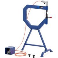
TBBD-1500LS - Drill MSW - Free user manual and instructions
Find the device manual for free TBBD-1500LS MSW in PDF.

| Product type | Bench drill press |
| Model | MSW-TBBD-1500LS |
| Nominal voltage | 230 V~ / 50 Hz |
| Nominal power | 390 / 550 W |
| Protection class | I |
| No-load speed | 400 - 2580 rpm |
| Protection rating | IP20 |
| Dimensions (L × W × H) | 490 × 300 × 870 mm |
| Weight | 25.4 kg |
| Table material | Cast iron / steel |
| Max. drilling diameter | 25 mm (steel) / 16 mm (cast iron) |
| Spindle stroke | Approx. 80 mm |
| Table tilt | Yes, adjustable |
| Adjustable table height | Yes, by crank |
| Digital speed display | Yes |
| Depth stop | Yes, with graduated ring |
| Centering laser | Yes, two lines |
| Chuck | Self-tightening chuck |
| Safety features | Chip guard, emergency stop |
| Cleaning | Unplug, wipe with soft cloth, vacuum chips |
| Lubrication | Moving parts regularly |
| Storage temperature | 5 °C to 30 °C |
Frequently Asked Questions - TBBD-1500LS MSW
User questions about TBBD-1500LS MSW
0 question about this device. Answer the ones you know or ask your own.
Ask a new question about this device
Download the instructions for your Drill in PDF format for free! Find your manual TBBD-1500LS - MSW and take your electronic device back in hand. On this page are published all the documents necessary for the use of your device. TBBD-1500LS by MSW.
USER MANUAL TBBD-1500LS MSW
natural_image
Mechanical assembly diagram showing a drill bit with labeled component '6' (no text or symbols beyond label)
natural_image
Close-up of a mechanical assembly with labeled components (11), no readable text or symbols present.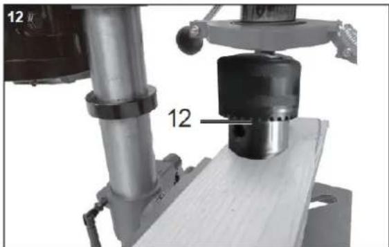
natural_image
Mechanical assembly diagram showing a cylindrical component mounted on a workbench, with no visible text or symbols.


1) Einführung
Bitte beachten Sie:
This User Manual has been translated for your convenience using machine translation. Reasonable efforts have been made to provide an accurate translation; however, no automated translation is perfect nor is it intended to replace human translators. The official User Manual is the English version. Any discrepancies or differences created in the translation are not binding and have no legal effect for compliance or enforcement purposes. If any questions arise related to the accuracy of the information contained in the User Manual, please refer to the English version of those contents which is the official version.
Technical data
| Parameter description Parameter value | |
| Product name | Bench Top Drill Press |
| Model | MSW-TBBD-1500LS |
| Rated voltage [V~] / frequency [Hz] | 230/50 |
| Rated power [W] | 390/550 |
| Protection class | I |
| No Load Speed [rpm] | 400-2580 |
| Protection rating IP | IP20 |
| Dimensions [width x depth x height; mm] | 490 x 300 x 870 |
| Weight [kg] | 25.4 |
1

natural_image
Mechanical assembly diagram showing a drill bit with labeled component '6' (no text or symbols beyond label)
natural_image
Close-up of a mechanical assembly with labeled components (no readable text or symbols)
natural_image
Mechanical assembly diagram showing a cylindrical component mounted on a workbench, with no visible text or symbols.


1) Introduction
Please consider:
Read through the complete text in the operating manual before installing and commissioning the device. The operating manual is intended to help the user to become familiar with the machine and take advantage of its application possibilities in accordance with the recommendations.
The device may only be used by personnel who have been trained to use it and who have been instructed with respect to the associated hazards.
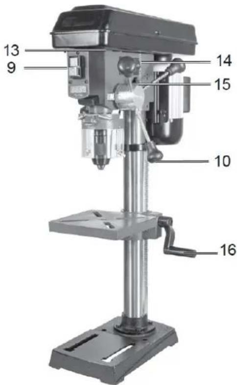
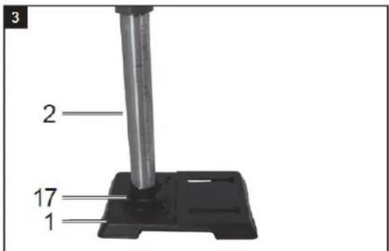
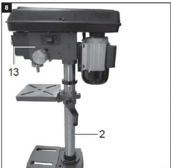
2) Device description
- Machine foot
- Column
-
Clamping handle
-
Drilling table
-
Motor
-
Speed adjustment lever (handle)
-
V-belt cover
-
Digital display
-
ON/OFF switch
-
Handle
-
Folding swarf protector
-
Drill chuck
-
Machine head
-
Depth indicator with stop
-
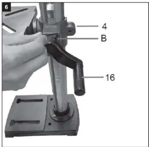
Crank handle
-
Screw
A. Allen key 4 mm
B. Allen key 3 mm
C. Battery
3) Proper use
Please observe that our equipment was not designed with the intention of use for commercial or industrial purposes. We assume no guarantee if the equipment is used in commercial or industrial applications, or for equivalent work.
4) General safety information
Work area safety
a) Keep work area clean and well lit. Cluttered or dark areas invite accidents.
b) Do not operate power tools in explosive atmospheres, such as in the presence of flammable liquids, gases or dust. Power tools create sparks which may ignite the dust or fumes.
c) Keep children and bystanders away while operating a power tool. Distractions can cause you to lose control.
Electrical safety
a) Power tool plugs must match the outlet. Never modify the plug in any way. Do not use any adapter plugs with earthed (grounded) power tools. Unmodified plugs and matching outlets will reduce risk of electric shock.
b) Avoid body contact with earthed or grounded surfaces, such as pipes, radiators, ranges and refrigerators. There is an increased risk of electric shock if your body is earthed.
c) Do not expose power tools to rain or wet conditions. Water entering a power tool will increase the risk of electric shock.
d) Do not use the cable for another purpose, for example, carrying or hanging the power tool or pulling the plug out of the socket. Keep the cable away from heat, oil, sharp edges or moving device parts. Damaged or coiled cables increase the risk of an electric shock.
e) If you work with a power tool outdoors, only use extension cables that are also suitable for outdoor use. Using an extension cable suitable for outdoor use reduces the risk of an electric shock.
Personal safety
a) Stay alert, watch what you are doing and use common sense when operating a power tool. Do not use a power tool while you are tired or under the influence of drugs, alcohol or
medication. A moment of carelessness when using electrical tools can result in serious injuries.
b) Use personal protective equipment. Always wear eye protection. Protective equipment such as a dust mask, non-skid safety shoes, hard hat or hearing protection used for appropriate conditions will reduce personal injuries.
c) Prevent unintentional starting. Ensure the switch is in the off-position before connecting to power source and/or battery pack, picking up or carrying the tool. Carrying power tools with your finger on the switch or energising power tools that have the switch on invites accidents.
d) Remove any adjusting key or wrench before turning the power tool on. A tool or spanner that is located in a rotating device part may result in injuries.
e) Do not overreach. Always keep proper footing and balance. This enables better control of the power tool in unexpected situations.
f) Dress properly. Do not wear loose clothing or jewellery. Keep hair, clothing and gloves away from moving parts. Loose clothes, jewellery or long hair can be caught in moving parts.
g) If dust extraction and collection devices can be mounted, make sure that they are connected and used properly. Use of dust collection can reduce dust-related hazards.
h) Do not let familiarity gained from frequent use of tools allow you to become complacent and ignore tool safety principles. A careless action can cause severe injury within a fraction of a second.
Operation
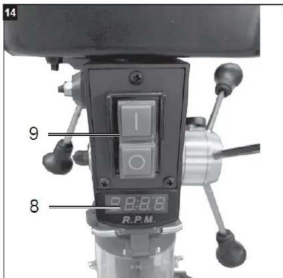
General.
To switch on, press the green On button 'I', the machine starts up. To switch off, press the red 'O' button, the appliance switches off.
Take care not to overload the appliance. If the motor noise drops during operation, the motor is being overloaded. Do not overload the appliance to such an extent that the motor comes to a standstill. Always stand in front of the machine during operation.
Insert the tool into the drill chuck.
Make sure that the mains plug is disconnected when changing tools. Only cylindrical tools with the specified maximum shank diameter may be clamped in the drill chuck. Only use tools that are in perfect condition and sharp. Do not use tools that are damaged on the shank or otherwise deformed or damaged in any way. Only use accessories and attachments that are specified in the operating instructions or approved by the manufacturer. If the bench drill jams, switch off the machine and return to the starting position with the drill.
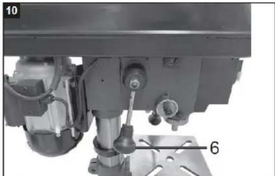
Speed adjustment.
The speed of the machine can be infinitely adjusted.
Caution!
- The speed may only be changed when the engine is running.
- Do not move the speed setting lever (6) jerkily; set the speed slowly and evenly while the machine is idling.
- Ensure that the machine can run unhindered (remove workpieces, drill bits, etc.).
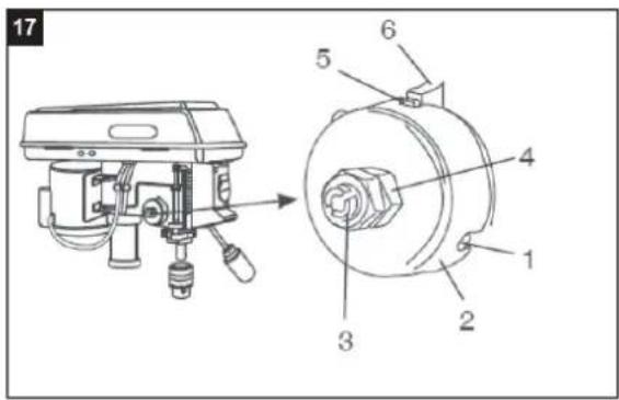
The speed can be continuously adjusted using the speed adjustment lever (6). The defined speed is shown in turns per minute on the digital display. Attention! Never let the drill run with the V-belt cover open. Always pull the mains plug before opening the cover. Never reach into running V-belts.
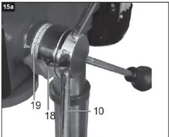
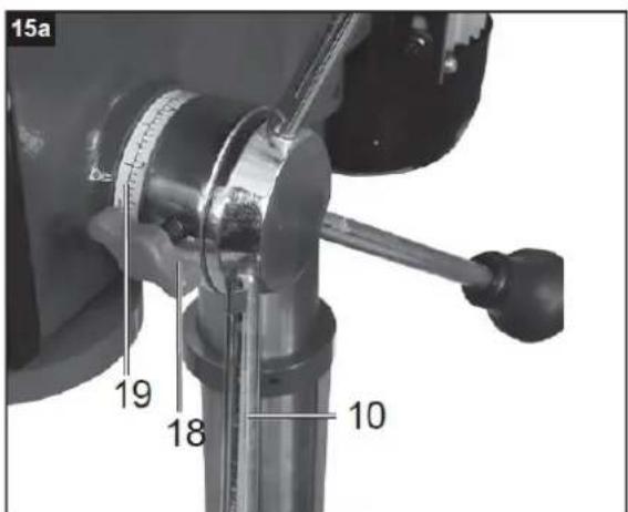
Drilling depth stop
The drilling spindle has a rotatable scale ring for setting the drilling depth. Only set up work while stopped.
- Press the drill spindle down until the drill tip lies on the workpiece.
- Loosen the clamping screw and turn the scale ring forward to the stop.
- Turn the scale ring back to the desired drilling depth and fix it with the clamping screw.
Attention! When setting the drilling depth of a cylindrical hole, you must add the length of the drill tip.
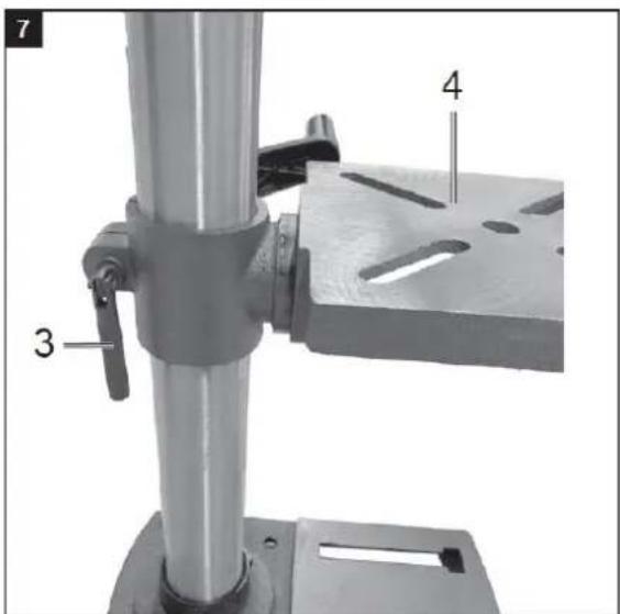
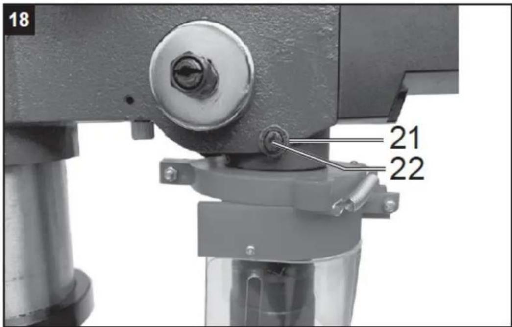
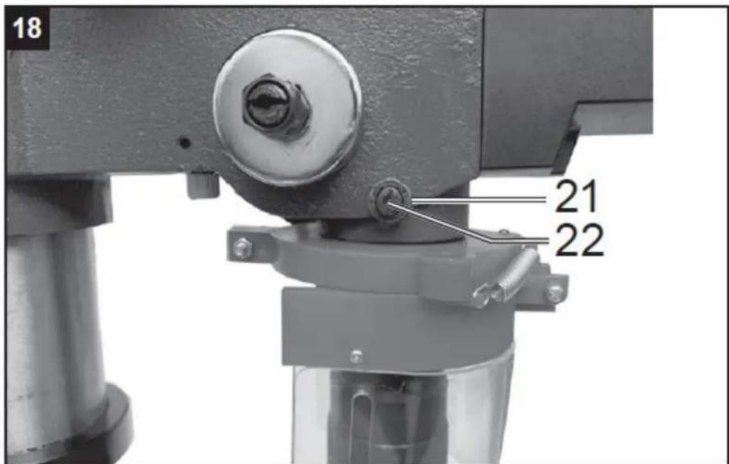
Adjust the inclination of the drilling table
- Loosen the hexagon screw under the drilling table.
- Set the drilling table to the desired angle.
- Tighten the coach bolt again to fix the drilling table in this position.
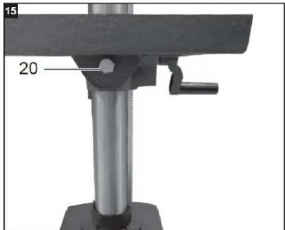
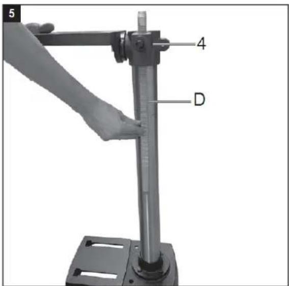
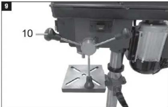
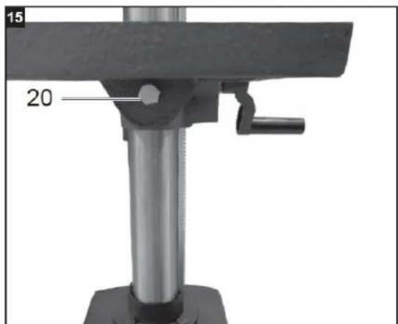
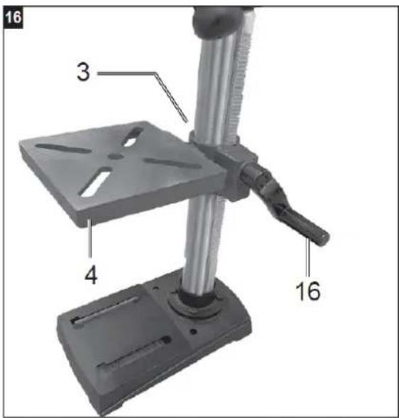
Adjust the height of the drilling table
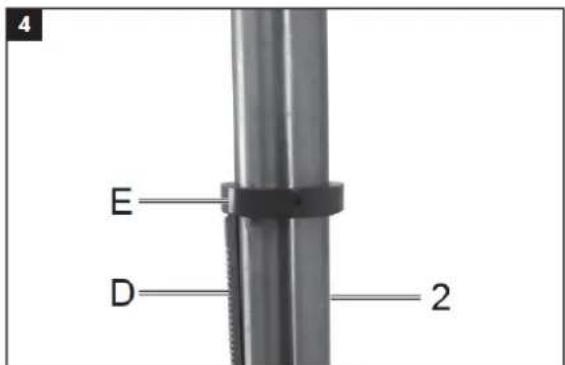
- Loosen the clamping screw.
- Put the drilling table into the required position using the crank handle.
- Retighten the clamping screw.
Drill table and roller support
- After loosening the clamping screw, the drilling table can be turned.
- After loosening the wing screws, the roller support can be pulled out.
Tensioning the workpiece
Always clamp workpieces firmly using a machine vice or with a suitable clamping device. Never hold workpieces by hand! When drilling, the workpiece should be movable on the drilling table so that self-centring can take place. Always secure the workpiece against twisting. The best way to do this is to place the workpiece or machine vice against a fixed stop.
Attention! Metal parts must be clamped so that they cannot be pulled up. Depending on the workpiece, correctly adjust the height and inclination. There must be enough distance between the top of the workpiece and the tip of the drill.
Laser operation
Switching on: Move the on/off switch laser into the "I" position to switch on the laser. Two laser lines are projected onto the workpiece to be processed, the intersection of which indicates the centre of the drill tip.
Switching off: Move the on/off switch laser into the "0" position.
Working speed
Ensure correct speed during drilling. This depends on the drill diameter and the material.
The list below will help you choose speeds for different materials.
The speeds indicated are only guidelines.
| Drill diameter | Grey cast iron | Steel | Iron | Aluminium | Bronze |
| 3 | 2550 | 1600 | 2230 | 9500 | 8000 |
| 4 | 1900 | 1200 | 1680 | 7200 | 6000 |
| 5 | 1530 | 955 | 1340 | 5700 | 4800 |
| 6 | 1270 | 800 | 1100 | 4800 | 4000 |
| 7 | 1090 | 680 | 960 | 4100 | 3400 |
| 8 | 960 | 600 | 840 | 3600 | 3000 |
| 9 | 850 | 530 | 740 | 3200 | 2650 |
| 10 | 765 | 480 | 670 | 2860 | 2400 |
| 11 | 700 | 435 | 610 | 2600 | 2170 |
| 12 | 640 | 400 | 560 | 2400 | 2000 |
| 13 | 590 | 370 | 515 | 2200 | 1840 |
| 14 | 545 | 340 | 480 | 2000 | 1700 |
| 16 | 480 | 300 | 420 | 1800 | 1500 |
| 18 | 425 | 265 | 370 | 1600 | 1300 |
| 20 | 380 | 240 | 335 | 1400 | 1200 |
| 22 | 350 | 220 | 305 | 1300 | 1100 |
| 25 | 305 | 190 | 270 | 1150 | 950 |
5) Cleaning and maintenance
Pull out the mains plug before carrying out any adjustments, maintenance or repair work.
Have tasks that are not described in this operating manual, carried out by a specialist workshop. Use only original parts. Let the device cool down before all maintenance and cleaning tasks. There is a risk of burns! Before using the device each time, check the device for obvious defects such as worn or damaged parts, correct seating of screws or other parts. Replace damaged parts.
Cleaning
Do not use cleaning agents or solvents. Chemical substances could damage the plastic parts of the device. Never clean the device under running water.
- Clean the device thoroughly after each use.
- Clean the ventilation holes and the surface of the device with a soft brush or cloth.
- Remove chips, dust and dirt with a vacuum cleaner if necessary.
- Lubricate the moving parts regularly.
- Do not allow lubricants to get onto switches, Vbelts, drive pulleys and drill stroke arms.
6) Storage
Store the device and its accessories in a dark, dry and frost-free place that is inaccessible to children.
The optimum storage temperature lies between 5 and 30 °C.
Store the power tool in its original packaging.
Cover the power tool to protect it from dust or moisture.
7) Disposal and recycling
The device is supplied in packaging to avoid transport damages. This packaging is raw material and can thus be used again or can be reintegrated into the raw material cycle. The device and its accessories are made of different materials, such as metals and plastics. Take defective components to special waste disposal sites. Check with your specialist dealer or municipal administration! Old devices must not be disposed of with household waste!


natural_image
Mechanical assembly diagram showing a drill bit with labeled component '6' (no text or symbols beyond label)
natural_image
Close-up of a mechanical assembly with labeled components (11), no readable text or symbols present.
natural_image
Mechanical assembly diagram showing a cylindrical component mounted on a workbench, with no visible text or symbols.


1) Wstęp
natural_image
Mechanical assembly diagram showing a drill bit with labeled component '6' (no text or symbols beyond label)
natural_image
Close-up of a mechanical assembly with labeled components (no readable text or symbols)
natural_image
Mechanical assembly diagram showing a cylindrical component mounted on a workbench, with no visible text or symbols.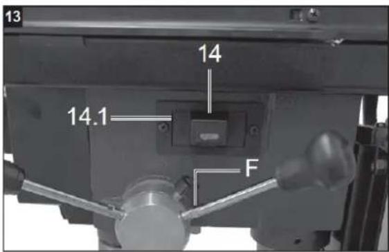


1) Introduction
natural_image
Mechanical assembly diagram showing a drill bit with labeled component '6' (no text or symbols beyond label)
natural_image
Close-up of a mechanical assembly with labeled components (11), no readable text or symbols present.
natural_image
Mechanical assembly diagram showing a cylindrical component mounted on a workbench, with no visible text or symbols.


1) Introduzione
natural_image
Mechanical assembly diagram showing a drill bit with labeled component '6' (no text or symbols beyond label)
natural_image
Close-up of a mechanical assembly with labeled components (11), no readable text or symbols present.
natural_image
Mechanical assembly diagram showing a cylindrical component mounted on a workbench, with no visible text or symbols.


1) Introducción
natural_image
Mechanical assembly diagram showing a drill bit with labeled component '6' (no text or symbols beyond label)
natural_image
Close-up of a mechanical assembly with labeled components (11), no readable text or symbols present.
natural_image
Mechanical assembly diagram showing a cylindrical component mounted on a workbench, with no visible text or symbols.


1) Bevezetés
natural_image
Mechanical assembly diagram showing a drill bit with labeled component '6' (no text or symbols beyond label)
natural_image
Close-up of a mechanical assembly with labeled components (11), no readable text or symbols present.
natural_image
Mechanical assembly diagram showing a cylindrical component mounted on a workbench, with no visible text or symbols.


1) Indledning
Overvej venligst:
natural_image
Mechanical assembly diagram showing a drill bit with labeled component '6' (no text or symbols beyond label)
natural_image
Close-up of a mechanical assembly with labeled components (11), no readable text or symbols present.
natural_image
Mechanical assembly diagram showing a cylindrical component mounted on a workbench, with no visible text or symbols.


1) Johdanto
Ota huomioon:
natural_image
Mechanical assembly diagram showing a drill bit with labeled component '6' (no text or symbols beyond label)
natural_image
Close-up of a mechanical assembly with labeled components (11), no readable text or symbols present.
natural_image
Mechanical assembly diagram showing a cylindrical component mounted on a workbench, with no visible text or symbols.


1) Invoering
natural_image
Mechanical assembly diagram showing a drill bit with labeled component '6' (no text or symbols beyond label)
natural_image
Close-up of a mechanical assembly with labeled components (11), no readable text or symbols present.
natural_image
Mechanical assembly diagram showing a cylindrical component mounted on a workbench, with no visible text or symbols.


1) Introduksjon
Vennligst vurder:
natural_image
Mechanical assembly diagram showing a drill bit with labeled component '6' (no text or symbols beyond label)
natural_image
Close-up of a mechanical assembly with labeled components (11), no readable text or symbols present.
natural_image
Mechanical assembly diagram showing a cylindrical component mounted on a workbench, with no visible text or symbols.


1) Inledning
Vänligen överväg:
natural_image
Mechanical assembly diagram showing a drill bit with labeled component '6' (no text or symbols beyond label)
natural_image
Close-up of a mechanical assembly with labeled components (11), no readable text or symbols present.
natural_image
Mechanical assembly diagram showing a cylindrical component mounted on a workbench, with no visible text or symbols.


1) Introdução
natural_image
Mechanical assembly diagram showing a drill bit with labeled component '6' (no text or symbols beyond label)
natural_image
Close-up of a mechanical assembly with labeled components (11), no readable text or symbols present.
natural_image
Mechanical assembly diagram showing a cylindrical component mounted on a workbench, with no visible text or symbols.


1) Úvod
Zvážte:
natural_image
Mechanical assembly diagram showing a drill bit with labeled component '6' (no text or symbols beyond label)
natural_image
Close-up of a mechanical assembly with labeled components (11), no readable text or symbols present.
natural_image
Mechanical assembly diagram showing a cylindrical component mounted on a workbench, with no visible text or symbols.


1) Въведение
natural_image
Mechanical assembly diagram showing a drill bit with labeled component '6' (no text or symbols beyond label)
natural_image
Close-up of a mechanical assembly with labeled components (11), no readable text or symbols present.
natural_image
Mechanical assembly diagram showing a cylindrical component mounted on a workbench, with no visible text or symbols.


1) Εισαγωγή
Λάβετε υπόψη:
natural_image
Mechanical assembly diagram showing a drill bit with labeled component '6' (no text or symbols beyond label)
natural_image
Close-up of a mechanical assembly with labeled components (11), no readable text or symbols present.
natural_image
Mechanical assembly diagram showing a cylindrical component mounted on a workbench, with no visible text or symbols.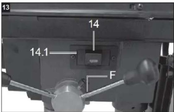


1) Ivadas
Apsvarstykite:
natural_image
Mechanical assembly diagram showing a drill bit with labeled component '6' (no text or symbols beyond label)
natural_image
Close-up of a mechanical assembly with labeled components (no readable text or symbols)
natural_image
Mechanical assembly diagram showing a cylindrical component mounted on a workbench, with no visible text or symbols.


1) Introducere
natural_image
Mechanical assembly diagram showing a drill bit with labeled component '6' (no text or symbols beyond label)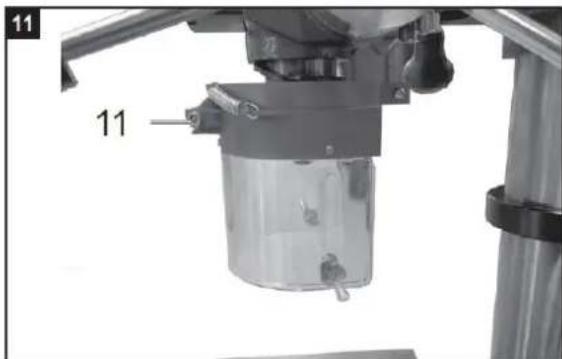
natural_image
Close-up of a mechanical assembly with labeled components (no readable text or symbols)
natural_image
Mechanical assembly diagram showing a cylindrical component mounted on a workbench, with no visible text or symbols.


1) Uvod
Upoštevajte:
For the disposal of the device please consider and act according to the national and local rules and regulations.
CONTACT
expondo Polska sp. z o.o. sp. k.