OP67S - Pump MSW - Free user manual and instructions
Find the device manual for free OP67S MSW in PDF.

| Product type | Electric oil pump |
| Brand | MSW |
| Model | OP67S |
| Rated voltage | 230 V / 50 Hz |
| Rated power | 360 W |
| Protection class | I |
| No-load speed | 2800 rpm |
| Max. delivery head | 10 m |
| Max. flow rate | 60 L/min |
| Duty cycle | Continuous (30 min operation, 30 min rest) |
| Dimensions (L × W × H) | 292 × 155 × 255 mm |
| Net weight | 15.25 kg |
| Compatible fluids | Petrol, diesel, kerosene, mineral spirits |
| Sound level (at 1 m) | < 70 dB(A) |
| Thermal protection | Yes (automatic shutdown in case of overheating) |
| Suction connection | 1" NPT female |
| Discharge connection | 1" NPT |
| Integrated bypass valve | Yes (bypass) |
| Daily maintenance | Check connections, clean filter, inspect seals |
| Grounding required | Yes (continuous metal-to-metal contact) |
Frequently Asked Questions - OP67S MSW
User questions about OP67S MSW
0 question about this device. Answer the ones you know or ask your own.
Ask a new question about this device
Download the instructions for your Pump in PDF format for free! Find your manual OP67S - MSW and take your electronic device back in hand. On this page are published all the documents necessary for the use of your device. OP67S by MSW.
USER MANUAL OP67S MSW
natural_image
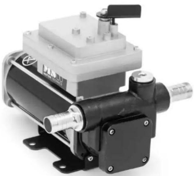
Exterior view of a motor pump assembly (no visible text or symbols on the device body)
DE
This User Manual has been translated for your convenience using machine translation. Reasonable efforts have been made to provide an accurate translation; however, no automated translation is perfect nor is it intended to replace human translators. The official User Manual is the English version. Any discrepancies or differences created in the translation are not binding and have no legal effect for compliance or enforcement purposes. If any questions arise related to the accuracy of the information contained in the User Manual, please refer to the English version of those contents which is the official version.
| Parameter description | Parameter value | |
| Product name | Oil Pump | |
| Model | MSW-OP67S | MSW-OP67 |
| Rated voltage [V~] / Frequency [Hz] | 230 / 50 | |
| Rated power [W] 360 | ||
| Protection class I | ||
| No-load Speed: | 2800 | |
| Max. Pump Height [m] 10 | ||
| Max. Flow Rate [L/min] 60 | ||
| Duty cycle: Continuous | ||
| Dimensions [Width x Depth x Height; mm] | 292 x 155 x 255 | 290 x 155 x 245 |
| Weight [kg] | 15.25 | 11.35 |
natural_image
Exterior view of a motor pump assembly (no visible text or symbols on the device body)
WARNING: Read carefully and understand all ASSEMBLY AND OPERATION INSTRUCTIONS before operating. Failure to follow the safety rules and other basic safety precautions may result in serious personal injury.
READ & SAVE THESE INSTRUCTIONS
Save the receipt, warranty, and this manual. It is important that you read the entire manual to become familiar with this product before you begin using it.
This fuel transfer pump is designed for certain applications only. We are not responsible for issues arising from modification or improper use of this product such as an application for which it was not designed. We strongly recommend that this product not be modified and/or used for any application other than that for which it was designed.
Intended Use
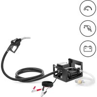
The device is designed to safely and efficiently transfer fuel from one container to another, commonly used for refueling vehicles, machinery, or equipment. It is particularly useful in situations where gravity-fed fuel transfer is impractical or when large volumes need to be moved quickly. The device typically features a motorized pump that provides consistent flow, reducing manual effort and minimizing spillage or waste.
Electrical Specifications
Important Safety Information
⚠ WARNING
- Read and understand all instructions. Failure to follow these instructions may result in serious injury or property damage.
- Warnings and Instructions: The warnings, cautions, and instructions provided in this manual cannot cover every possible condition or situation that could arise. Use common sense and caution when operating this tool. Always be mindful of your environment and ensure that the tool is used safely and responsibly.
- Operator Responsibility: Do not allow anyone to operate or assemble the product until they have thoroughly read this manual and understand how the tool works.
- No Modifications: Do not modify this product in any way. Unauthorized modifications may compromise its functionality and safety, potentially shortening its lifespan. This product is designed for specific applications, and modifying it could lead to malfunction or danger.
- Use the Correct Tool: Use the appropriate tool for the task. Do not try to make small equipment perform the job of larger industrial equipment. This product is designed for certain applications and will be safer and more effective when used within its intended capacity. Do not use this equipment for any purpose other than what it was designed for.
- Compliance with OSHA: For industrial or commercial applications, ensure that all OSHA requirements are followed.
⚠ WARNING
WORK AREA SAFETY
- Inspect the Work Area: Before each use, inspect the work area. Ensure that it is clean, dry, free of clutter, and well-lit. Cluttered, wet, or dark work areas can lead to injury. Using the product in confined spaces may put you dangerously close to cutting tools and rotating parts.
- Avoid Fire and Explosion Risks: Do not use the product in environments where there is a risk of fire or explosion, such as in the presence of flammable liquids, gases, or dust. The product can create sparks, which could ignite these substances.
- Electrical Safety: Keep the product away from electrical sources. The tool is not insulated and contact with electricity can cause an electric shock.
- Keep Children and Bystanders Away: Ensure that children and bystanders are kept at a safe distance from the work area while operating the tool. Children should not be allowed to handle the product.
- Be Aware of Hazards: Be mindful of all power lines, electrical circuits, water pipes, and other mechanical hazards in your work area. Some hazards may be hidden from view and could cause personal injury and/or property damage if contacted.
⚠ WARNING
PERSONAL SAFETY
- Stay Alert: Always stay focused and use common sense when operating the tool. Do not use the tool if you are tired or under the influence of drugs, alcohol, or medication. A moment of inattention can lead to serious personal injury.
- Dress Properly: Avoid wearing loose clothing, dangling objects, or jewelry. Keep your hair, clothing, and gloves away from moving parts. Loose items can easily get caught in moving parts, and air vents on the tool often cover these moving parts and should be avoided.
- Wear Proper Protective Equipment: Always wear appropriate personal protective equipment. Use safety goggles (not just safety glasses) with side shields, or a face shield if necessary. Wear a dust mask in dusty environments. Also, use non-skid safety shoes, a hardhat, gloves, dust collection systems, and hearing protection as needed. This applies to everyone in the work area.
- Maintain Proper Balance: Do not overreach. Keep a stable footing and maintain your balance at all times while operating the tool.
- Remove Keys or Wrenches: Always remove any keys or wrenches before connecting the tool to an air supply, power supply, or before turning on the tool. A wrench or key left attached to a rotating part can cause personal injury.
- Secure the Workpiece: When practical, secure the workpiece with clamps or a vise instead of holding it with your hand. This precaution allows for safer tool operation, enabling you to use both hands effectively.
⚠CAUTION
PUMP USE AND CARE
- Do Not Force the Pump: Products are safer and perform better when used as intended. Plan your work carefully and use the correct product for the job.
- Inspect for Damage: Before each use, check for damaged parts. Ensure that the product operates properly and performs its intended function. Replace any damaged or worn parts immediately. Never operate the product with damaged parts.
- Check the Switch: Do not use a product with a malfunctioning switch. Any power tool that cannot be controlled with the power switch is dangerous and should be repaired by an authorized service representative before use.
- Disconnect Power/Air Supply: Always disconnect the power or air supply and place the switch in the locked or off position before making any adjustments, changing accessories, or storing the tool. These preventive measures reduce the risk of accidental startup.
- Proper Storage: Store the product in a dry, secure place out of the reach of children when not in use. Inspect the tool to ensure it is in good working condition before storage and before re-use.
- Use Recommended Accessories: Only use accessories recommended by the manufacturer for your product. Accessories that may work well with one product could
create a risk of injury when used with another. Never use an accessory with a lower operating speed or pressure than the tool itself.
- Keep Guards in Place: Always keep safety guards in place and in proper working order. Never operate the product without these guards.
- Do Not Leave Unattended: Never leave the tool running unattended. Always ensure the tool is properly turned off and secured when not in use.
Specific Operation Warnings
⚠ WARNING
To prevent serious injury or property damage, please read and fully understand the owner's manual before operating this equipment.
- Follow Safety Codes: Be aware of and adhere to all applicable national, state, and local safety codes regarding the installation and operation of electrical equipment for use with flammable liquids.
- Handle Fuels Safely: Follow all safety precautions when handling petroleum fuels.
- Provide Instructions: Ensure all equipment operators have access to adequate instructions on safe operating and maintenance procedures.
- Proper Grounding: For safe operation, all fuel transfer systems must be properly grounded. Proper grounding involves continuous metal-to-metal contact between all components, including the tank, bung, pump, meter, filter, hose, and nozzle. Ensure proper grounding during initial installation and after any service or repair.
- Fire and Explosion Precautions: To prevent physical injury, take precautions against fire or explosion when dispensing fuel. Do not operate the system near any sources of ignition, including running or hot engines, lighted cigarettes, or gas or electric heaters.
- Electrical Shock Precautions: Take precautions against electrical shock when operating the system. Serious or fatal shock can occur if operating electrical equipment in damp or wet locations.
- Inspect Wiring: Regularly inspect external pump wiring to ensure it is correctly connected to the battery. Take extra care to avoid electrical shock when connecting the pump to power.
- Protect Against Fuel Exposure: Avoid prolonged skin contact with petroleum fuels. Wear protective goggles, gloves, and aprons if splashing or spills are possible. Change saturated clothing immediately and wash skin with soap and water.
- Power Off Before Connecting: Ensure the power switch is in the off position before connecting the power.
- Wear Protective Gear: Always wear proper protective gear, including ANSI Z87.1 compliant safety goggles, while operating the equipment.
- Service Safely: Take precautions against electrical shock when servicing the pump. Always disconnect power before repairing or servicing. Never apply electrical power to the system when any cover plates are removed.
- Use Solvents Safely: If using solvents to clean pump components or the tank, follow the solvent manufacturer's recommendations for safe use and disposal.
• Professional Wiring: Electrical wiring should be done by a licensed electrician in
compliance with local codes. Use a rigid conduit, and ensure proper grounding to avoid electrical shock. Failure to comply could result in serious injury and/or loss of property. Use only static wire and a conductive hose when pumping flammable fluids.
- Usage Restrictions: This product should not be used for fluid transfer into an aircraft and is not suitable for fluids intended for human consumption or fluids containing water.
- Motor Operation: Extreme operating conditions with working cycles longer than 30 minutes can cause the motor temperature to rise, potentially damaging the motor. After each 30-minute working cycle, allow the motor to cool for 30 minutes.
- Pipe Threads: Use PTFE tape on all pipe threads.
- Bypassing and Dry Running Limits: Do not exceed a maximum bypassing time of 30 minutes, and do not run the pump dry for more than 30 seconds.
- Burn Hazard: To reduce the risk of burns, avoid touching hot surfaces.
- Circuit Safety: Disconnect the circuit before removing the cover, and ensure the enclosure is tightly closed when circuits are live.
- Seal Installation: A seal must be installed within 50mm of the enclosure to ensure safety. By following these safety precautions, you can help prevent accidents and ensure the safe and effective operation of your equipment.
Assembly Instructions
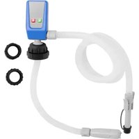
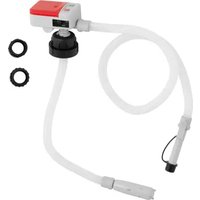
Suction Pipe Installation:
- Tightly screw all suction pipe sections together and secure them into the 1" female end of the tank adapter.
- Extend the suction pipe into the truck tank or barrel, ensuring it reaches within 3 inches of the tank bottom.
Adapter Installation:
- Screw the adapter into the 2" opening of the tank or barrel.
- Ensure that the inlet coupling is completely and securely threaded into an undamaged tank or barrel bung.
Electrical Safety:
- During installation and maintenance, ensure that the electrical supply lines are not live.
• Always turn off the switch before supplying electrical power.
DC Pump Rotation Check:
- Verify the correct rotation direction of the DC pump. If the rotation is incorrect, check the polarity of the connection cables:
- BLACK cable: Connect to the positive pole (+).
- WHITE cable: Connect to the negative pole (-).
System Design Considerations:
- Design the system to minimize the amount of suction lift required. The maximum "equivalent feet of lift" is 8 feet for diesel fuel.
Ventilation and Filtration:
- Ensure that the tank or barrel is properly vented.
- Use a water separator when pumping diesel fuel to prevent contamination.
Installation on a skid tank
When installing the pump on a skid tank, use the threaded inlet supplied with the pump (refer to the attached diagrams). The pump includes an integral bypass valve that recirculates fluid when the pump operates with the nozzle closed.
Important Safety Notes:
WARNING!
- In skid tank applications, ensure the tank is properly secured to prevent any movement, whether the tank is empty or full.
CAUTION!
- Do not use additional check valves or foot valves unless they have a proper pressure relief valve built into them. Additional check valves will reduce the flow rate.
- A pressure-retaining fill cap can be used to minimize fuel loss through evaporation but be aware that it will also reduce the flow rate.
WARNING!
- This pump is designed for use with both stationary and mobile tank applications. DC-powered units are an excellent choice for mobile applications, but it is crucial to anchor the tank to which the pump is mounted securely. Failing to secure the tank during transit can result in uncontrolled movement, leading to damage, injury, and potential fire.
Installation Procedure:
1. Mounting the Pump:
- The pump mounts to the bung of a skid tank via the inlet flange.
The suction tube threads into the bottom of the inlet flange and must extend to a length that positions it at least 3 inches from the bottom of the tank.
2. Vent Cap:
- The skid tank should be equipped with a vent cap to allow proper ventilation.
3. Suction Pipe Installation:
○ Tightly screw all suction pipe sections together.
Screw the suction pipe into the 1" female end of the tank adapter and extend the suction pipe into the skid tank or barrel, ensuring it reaches within 3 inches of the tank bottom.
- Screw the adapter into the 2" tank opening.
- Ensure the inlet coupling is completely and securely threaded into an undamaged tank bung.

A Pump
Vent Cap
B
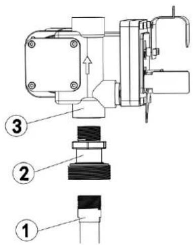
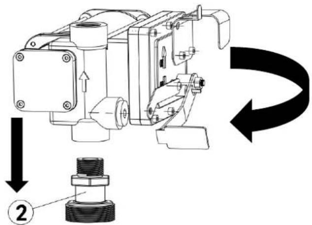
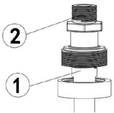
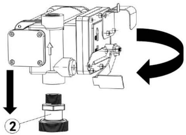
Installation Procedure::
- Thread the 1" pipe into the tank adapter. Seal threads liquid tight with appropriate sealant.
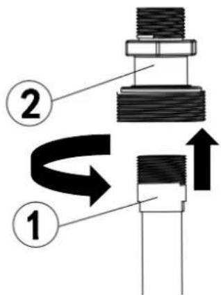
- Screw the inlet flange (with suction pipe) into the tank bung; seal threads liquid tight with appropriate thread sealant.

3 Mount the pump on the adapter; making sure the seal and screen are installed as shown. (Figure 3).
Electrical Installation Instructions:
1. Access the Wires:
- Remove the pump's junction box cover.
- Straighten the two wires inside to make the stripped wire ends accessible outside of the junction box.
2. Install the Cable Connector:
- Screw the provided cable connector into the 1/2" NPT conduit opening in the pump junction box.
3. Prepare the Electrical Cable:
- Strip 6 inches of the outer covering from one end of the provided electrical cable, taking care not to damage the insulation on the black and red wires.
4. Secure the Cable:
- Loosen the cable connector nut.
- Pass the stripped end of the electrical cable through the cable connector until 2 inches of the unstripped cable is inside the connector.
- Tighten the cable connector nut to secure the cable in place.
5. Connect the Wires:
- Strip 1/2" of insulation from the ends of the red and black wires.
- Using the provided wire nuts, connect these wires to the corresponding wires on the pump, matching the colors (red to red, black to black).
- Ensure that no bare wire is exposed after connecting.
6. Replace the Junction Box Cover:
- Carefully fold the wires into the junction box.
- Replace the junction box cover, ensuring the gasket is in place.
- Tighten all screws to ensure there is no space between the cover and the junction box.
7. Use Proper Safety Equipment:
- Ensure you use an explosion-proof power cord and a strain relief sealing grip for added safety.
Before Each Use
⚠ WARNING
- To prevent serious injury or property damage, carefully read and understand the owner's manual before operating.
- Follow Safety Codes: Know and adhere to all applicable national, state, and local safety codes for installing and operating electrical equipment with flammable liquids.
- Petroleum Fuel Safety: Follow all safety precautions when handling petroleum fuels.
- Provide Adequate Instructions: Ensure all equipment operators have access to and understand the safe operating and maintenance procedures.
- Proper Grounding: All fuel transfer systems must be properly grounded. This requires continuous metal-to-metal contact from one component to the next, including the tank, bung, pump, meter, filter, hose, and nozzle. Proper grounding must be verified during initial installation and after any service or repair.
- Fire and Explosion Precautions: To prevent physical injury, take precautions against fire or explosion when dispensing fuel. Do not operate the system near any sources of ignition, such as running or hot engines, lighted cigarettes, or gas or electric heaters.
-
Electrical Shock Precautions: Avoid electrical shock by not operating the system in damp or wet locations. Serious or fatal shocks can occur in such conditions.
-
Power Switch Safety: Ensure the power switch is in the off position before connecting power.
- Protective Gear: Wear the proper protective gear, including ANSI Z87.1 compliant safety goggles, while operating the equipment.
- Servicing Precautions: When servicing the pump, always disconnect power before starting repairs. Never apply electrical power when any cover plates are removed.
- Circuit Safety: Disconnect the circuit before removing the cover. Ensure the enclosure is tightly closed when circuits are live.
Operating Instructions
⚠ WARNING
- Follow Safety Codes: Understand and adhere to all applicable national, state, and local safety codes related to the installation and operation of electrical equipment for use with flammable liquids.
- Petroleum Fuel Safety: Always follow safety precautions when handling petroleum fuels.
- Provide Adequate Instructions: Ensure that all equipment operators have access to proper instructions regarding safe operation and maintenance procedures.
- Proper Grounding: All fuel transfer systems must be properly grounded to ensure safe operation. Proper grounding involves continuous metal-to-metal contact from one component to the next, including the tank, bung, pump, meter, filter, hose, and nozzle. This must be confirmed during initial installation and after any service or repair.
- Fire and Explosion Precautions: To prevent physical injury, observe all precautions against fire or explosion when dispensing fuel. Do not operate the system near any sources of ignition, including running or hot engines, lighted cigarettes, or gas/electric heaters.
- Electrical Shock Precautions: Take care to avoid electrical shock when operating the system. Operating electrical equipment in damp or wet locations can result in serious or fatal shocks.
- Inspect Wiring Regularly: Regularly inspect external pump wiring to ensure it is correctly connected to the battery. Use extra caution when connecting the pump to power to avoid electrical shock.
- Avoid Skin Contact with Fuels: Minimize prolonged skin contact with petroleum fuels. Wear protective goggles, gloves, and aprons in case of splashing or spills. If clothing becomes saturated, change immediately and wash the skin with soap and water.
- Proper Protective Gear: Always wear the appropriate protective gear, including safety goggles, while operating the equipment.
- Prohibited Uses: This product should not be used for fluid transfer into an aircraft. It is also not suitable for use with fluids intended for human consumption or fluids containing water.
- Operating Conditions: Avoid extreme operating conditions. Working cycles longer than 30 minutes can cause the motor temperature to rise, potentially damaging the motor. Allow for a 30-minute power-off cooling phase after each 30-minute working cycle.
- Use of PTFE Tape: Use PTFE tape on all pipe threads to ensure secure and leak-free connections.
- Bypass Time and Dry Running: Do not exceed the maximum bypassing time of 30 minutes. Additionally, do not run the pump dry for more than 30 seconds.
- Burn Hazard: To reduce the risk of burns, avoid touching hot surfaces.
FLUID COMPATIBILITY
These products are compatible with the following fluids:
Gasoline, Diesel, Kerosene, and Mineral Spirits
CAUTION
Do NOT use with other fluids without consulting the manufacturer.
Operating Instructions:
- Flexible Tubing Setup:
- If using flexible tubing, securely attach the ends of the tubing to the tanks. If there is no appropriate slot available, firmly grasp the delivery tube before beginning to dispense.
- Check Delivery Valve:
Before starting the pump, ensure that the delivery valve (such as the dispensing nozzle or line valve) is closed.
- Start the Pump:
Turn the ON/OFF switch to the "ON" position. Note that the by-pass valve allows the pump to function with the delivery closed, but only for brief periods.
- Begin Dispensing:
- Open the delivery valve while securely holding the end of the tubing.
- Stop Dispensing:
- Close the delivery valve to stop the flow of the fluid.
- Turn Off the Pump:
Once dispensing is complete, turn off the pump to prevent any unnecessary operation.
After Each Use
⚠ WARNING
Solvent Use:
- If using a solvent to clean pump components or the tank, always follow the solvent manufacturer's recommendations for safe use and disposal. Proper handling and disposal are essential to prevent hazards.
Burn Hazard:
- To reduce the risk of burns, avoid touching any hot surfaces on the equipment.
Proper Storage:
- When the product is not in use, store it in a dry, secure place out of the reach of children.
- Before storing and reusing the tool, inspect it to ensure it is in good working condition.
Maintenance
Maintain the product by adopting a program of conscientious repair and maintenance in accordance with the following recommended procedures. It is recommended that the general condition of any tool be examined before it is used. Keep your tool in good repair. Keep handles dry, clean, and free from oil and grease. Also refer to the engine manufacturer's instruction manual for additional information about engine maintenance. The following chart is based on a normal operation schedule.
| Maintenance Interval | Maintenance Point |
| Daily operating | Under normal working conditions the noise emission from all models does not exceed the value of 70 db at a distance of 1 meter from the electric pump. |
Troubleshooting
Use the table below to troubleshoot problems before contacting service personnel or your local dealer. If the problem continues after troubleshooting, call your local dealer for assistance
| Failure | Possible Cause | Corrective Action |
| The motor is not turning | Lack of electric power | Check the electrical connections and the safety systems |
| Rotor jams | Check for possible damage or obstruction of the rotating components. | |
| Motor problems Contact with the service department | ||
| Thermal overload protection shuts down | A:When the thermal overload protection activate, please turn off the pump switch and dis-connect the cable from the power and wait for it to cool down and (then re-connect the cable to the power and turn on the pump switch again.) | |
| Low or no flow rate | Low level in the suction tank Refill the tank | |
| Foot valve blocked Clean and/or replace the valve | ||
| Filter clogged | Clean the filter | |
EN
| Excessive suction pressure | Lower the pump with respect to the level | |
| High loss of head in the circuit (working with the by-pass open) | Use shorter tubing or of greater diameter | |
| By-pass valve blocked | Dismantle the valve, clean and/or replace it | |
| Air entering the pump or the suction tubing | Check the seals of the connections | |
| A narrowing in the suction tubing | Use tubing suitable for working under suction pressure | |
| Low rotation speed | Check the voltage at the pump. Adjust the voltage and/or use cables of greater cross-section | |
| The suction tubing is resting on the bottom of the tank | Raise the tubing | |
| Increased pump noise | Cavitations occurring Reduce suction pressure | |
| Irregular functioning of the by-pass | Dispense until the air is purged from the circuit | |
| Air present in the diesel fuel | Verify the suction connections | |
| Leakage from the pump body | Seal damaged | Check and replace the mechanical sea |

natural_image
Exterior view of a motor pump assembly (no visible text or symbols on the device body)
BEZPIECZEŃSTWO W MIEJSCU PRACY
natural_image
Exterior view of a motor and pump assembly (no visible text or symbols)
Postup instalace: :
Pokyny k elektrické instalaci:
natural_image
Exterior view of a motor pump assembly (no visible text or symbols on the device body)
natural_image
Exterior view of a motor pump assembly (no visible text or symbols on the device body)
natural_image
Exterior view of a motor pump assembly (no visible text or symbols on the device body)
natural_image
Exterior view of a motor pump assembly (no visible text or symbols on the device body)
natural_image
Exterior view of a motor and pump assembly (no visible text or symbols)
Installationsprocedure: : .
Instruktioner for elektrisk installation:
natural_image
Exterior view of a motor pump assembly (no visible text or symbols on the device body)
Asennusmenettely: :
Sähköasennusohjeet:
1. Pääsy johtoihin:
natural_image
Mechanical pump assembly with motor and cylindrical body (no visible text or symbols)
natural_image
Mechanical pump assembly with motor and cylindrical body (no visible text or symbols)
ARBEIDSOMRÅDESIKKERHET
natural_image
Mechanical pump assembly with motor and cylindrical body (no visible text or symbols)
Adapterinstallation:
Installationsprocedur: :
natural_image
Exterior view of a motor pump assembly (no visible text or symbols on the device body)
natural_image
Exterior view of a motor pump assembly (no visible text or symbols on the device body)
natural_image
Exterior view of a motor pump assembly (no visible text or symbols on the device body)


natural_image
Mechanical pump assembly with black and white components, no visible text or symbolsnatural_image
Exterior view of a motor pump assembly (no visible text or symbols on the device body)
UPOZORENJE: Pažljivo pročitajte i shvatite sve UPUTE ZA SASTAVLJANJE I RAD prije rada. Nepoštivanje sigurnosnih pravila i drugih osnovnih mjera opreza može dovesti do ozbiljnih osobnih ozljeda.
PROČITAJTE I SPREMITE OVE UPUTE
- Zavrnite ulaznu prirubnicu (s usisnom cijevi) u čep spremnika; zabrtviti navoje nepropusno za tekućinu s odgovarajućim brtvilom za navoje.
3 Montirajte pumpu na adapter; pazeći da su brtva i zaslon postavljeni kao što je prikazano. (Slika 3).
Upute za električnu instalaciju:
natural_image
Exterior view of a motor and pump assembly (no visible text or symbols)


natural_image
Mechanical pump assembly with black and white components, no visible text or symbolsnatural_image
Exterior view of a motor pump assembly (no visible text or symbols on the device body)
Procedura de instalare ::
Instructiuni de instalare electrica:
1. Accesati firele:
natural_image
Exterior view of a motor pump assembly (no visible text or symbols on the device body)
Postopek namestitve: :
- Privijte 1" cev v adapter rezervoarja. Tesno tesnite navoje z ustreznim tesnilom.

- Privijte vstopno prirobnico (s sesalno cevjo) v čep rezervoarja; navoje tesno zatesnite z ustreznim tesnilom za navoje.

For the disposal of the device please consider and act according to the national and local rules and regulations.
CONTACT
expondo Polska sp. z o.o. sp. k.