PFT-120-M - Pump MSW - Free user manual and instructions
Find the device manual for free PFT-120-M MSW in PDF.

User questions about PFT-120-M MSW
0 question about this device. Answer the ones you know or ask your own.
Ask a new question about this device
Download the instructions for your Pump in PDF format for free! Find your manual PFT-120-M - MSW and take your electronic device back in hand. On this page are published all the documents necessary for the use of your device. PFT-120-M by MSW.
USER MANUAL PFT-120-M MSW
MSW-PFT-120-D / MSW-PFT-120-P

MONTAGE (MSW-PFT-120-M)
natural_image
Close-up of a red industrial machine with a black handle and mechanical components (no visible text or symbols)natural_image
Close-up of red industrial machinery components including a clamping tool and a metal bracket (no visible text or symbols)natural_image
Two red industrial equipment components: a motor pump with a transparent hose and a blue safety guard, both without visible text or symbols.natural_image
Close-up of a red fire extinguisher with metallic clamps and ventilation slots (no text or symbols visible)MONTAGE (MSW-PFT-120-D / MSW-PFT-120-P)
natural_image
Close-up of a metallic electrical connector with red and green wires, no visible text or symbolsnatural_image
Close-up of a metallic metal bracket with two bolts, set against a red background (no text or symbols visible)natural_image
Close-up of mechanical components with metallic fittings and a gray tool handle, set against red background (no visible text or symbols)This User Manual has been translated using machine translation. We have made every effort to ensure the translation is accurate, but please note that automated translations are not perfect and are not meant to replace human translators. The official version of the User Manual is in English. Any differences between the translated version and the original English are not legally binding. If you have any questions about the accuracy of the translation, please refer to the English version, which is the official reference. More language versions are available upon request via info@expondo.com
Technical data
| Parameter description Parameter value | |||
| Product name | Portable fuel tank | ||
| Model | MSW-PFT-120-M | MSW-PFT-120-D | MSW-PFT-120-P |
| Rated voltage [V~] / frequency [Hz] | - DC 12V | /50 | |
| Power {W} | - | 150 | 200 |
| Ip protection rating | - | IPX4 | |
| Motor revolutions [rpm] | - | 4200 | 3200 |
| Duty cycle - | S2(30 min. work/30 min. pause) | ||
| Tank capacity [l] | 120 | ||
| Max flow rate [L/min] | 20 | 40 | 62 |
| Max lift [m] | - | 7 | 9 |
| Dimensions [width x depth x height; mm] | 540 x 450 x 1065 | 540 x 430 x 1065 | 535 x 435 1065 |
| Weight [kg] | 21 | 23.9 | 28.5 |
| Distributor hose length [m] | ~2 | ~4 | ~4 |
1. General Description
The manual is intended to assist in safe and reliable use. The product is designed and manufactured strictly according to technical specifications using the latest technology and components and maintaining the highest quality standards.
DO NOT USE THE DEVICE UNLESS YOU HAVE THOROUGHLY READ AND UNDERSTOOD THIS USER MANUAL.
To ensure the long and reliable operation of the device, make sure to operate and maintain it properly following the guidelines in this instruction manual. The technical data and specifications in this manual are up-to-date. The manufacturer reserves the right to make changes to improve the quality. Taking the technical progress and the possibility of reducing noise into account, the unit is designed and built in such a way that risks resulting from noise emissions are reduced to the lowest possible level.
Explanation of symbols
| CE | The product complies with applicable safety standards. |
 | Read the manual before use. |
 | Recyclable product. |
 | CAUTION! or WARNING! or REMEMBER! describing a situation (general warning sign). |
 | Wear protective goggles. |
 | Wear protective gloves. |
 | Wear protective footwear. |
 | Use closure. |
 | CAUTION! Danger of fire - flammable material! |
 | Warning against poisoning by toxic substances! |

CAUTION! The figures in this manual are illustrative only and may vary in some details from the actual appearance of the product.
2. Safety of use
CAUTION! Read all safety warnings and instructions. Failure to follow warnings and instructions could result in serious injury or even death.
The term "device" or "product" in the warnings and in the description of the instructions refers to the:
Portable fuel tank.
2.1. Electrical safety
a) Do not modify the battery clamps in any way. Using original clamps reduces the risk of an short circuit etc.
b) Use the cable only for its designated use. Never use it to carry the device or to pull the plug out of a socket. Keep the cable away from heat sources, oil, sharp edges or moving parts. Damaged or tangled cables increase the risk of electric shock.
c) Do not use the device if the power cord is damaged or shows obvious signs of wear. A damaged power cord should be replaced by a qualified electrician or the manufacturer's service centre.
d) ATTENTION! DANGER TO LIFE! While cleaning, never immerse the device in water or other liquids.
2.2. Safety in the workplace
a) Keep the work area tidy and well-lit. Disorder or poor lighting can lead to accidents. Be foresighted, watch what you are doing and use common sense when using the device.
b) If you find any damage or irregularities in the operation of the product, immediately turn it off and report it to an authorized person.
c) Repairs to the device may only be carried out by the manufacturer's service. Do not attempt to repair the product on your own!
d) In case of open flames or fire, use only dry powder or snow (CO2) fire extinguishers to extinguish the live equipment.
e) No children or unauthorized persons are allowed in the work area. Inattention can cause losing control of the unit.
f) Use the unit in a well-ventilated area.
g) Check the condition of the safety stickers regularly. If the stickers are illegible, they must be replaced. In the event of ignition or fire, use only powder or snow (CO2) fire extinguishers to suppress the live device.
h) Keep this manual for future reference. If the unit is to be passed on to third parties, the operating instructions must also be handed over together with the unit.
i) Keep packaging components and small installation parts out of the reach of children.
j) Keep the device away from children and animals.
k) When using this product together with other devices, also follow the other instructions for use. Do not point the pressure hose toward yourself or other people or animals. Pressurized air can cause serious injury.

Remember! Keep children and other bystanders safe while operating the equipment.
2.3. Personal safety
a) Do not operate this device if you are tired, ill, or under the influence of alcohol, drugs, or medication that could impair your ability to operate the device.
b) The device is not intended to be used by persons (including children) with reduced mental, sensory, or intellectual functions or persons who lack experience and/or knowledge unless they are supervised or have been instructed by a person responsible for their safety on how to operate the device.
c) The unit may be operated by persons who are physically fit, capable of operating it, and appropriately trained, and who have read this instruction manual and have been trained in occupational safety and health.
d) Please be attentive and use common sense when operating this equipment. A moment's inattention during operation may result in serious personal injury.
e) Use the personal protective equipment required when working with the device, as specified in point 1. "Explanation of symbols." The use of appropriate, approved personal protective equipment reduces the risk of injury.
f) Do not overestimate your capabilities. Maintain body balance and equilibrium at all times during operation. This allows for better control of the machine in unexpected situations.
g) The product is not a toy. Children should be watched to ensure that they do not play with the appliance. To prevent accidental start-up, make sure the switch is in the off position before connecting to a power source.
2.4. Safe use of the product
a) Keep unused appliance out of the reach of children and anyone unfamiliar with the appliance or this manual. Products are dangerous when used by inexperienced users.
b) Keep the product in good working order. Check before each use for general damage or damage to moving parts (cracks in parts and components or any other condition that may affect the safe operation of the device). If damaged, return the device for repair before use. Unplug the unit before making adjustments, changing accessories, or putting it away. This precaution reduces the risk of accidental start-up.
c) Keep the product out of the reach of children.
d) Repairs and maintenance should be carried out by qualified personnel using only original spare parts. This will ensure the safety of use.
e) To ensure the designed operational integrity of the device, do not remove factory-installed covers or loosen screws.
f) When transporting or moving the device from storage to the place of use, observe the health and safety rules for manual handling applicable in the country where the device is used.
g) Avoid situations where the unit stops working because it is handling a heavy load. This can cause overheating of the drive elements and consequent damage to the equipment.
h) Do not move, shift, or rotate the device while in operation.
i) Clean the device regularly to prevent permanent dirt build-up.
j) Before each use, make sure that the nozzle is properly mounted in the machine and that the hose is properly attached and undamaged.
k) The product is not a toy. Cleaning and maintenance must not be performed by children without adult supervision.
I) Do not tamper with the device to alter its performance or design.
m) Keep the device away from sources of fire and heat, and never expose it to prolonged direct sunlight.
n) Do not overfill over the declared capacity!
o) Store it always in the upright position.

CAUTION! Although the product has been designed to be safe and has adequate safeguards and despite the additional safety features provided to the user, there is still a slight risk of accident or injury when handling the product. Caution and common sense are advised when using the product.
3. Instructions for use
The product is designed for the transportation, storage and distribution of fuel and operating or industrial oils (including, for e.g. used cooking oil). The device is not suitable for water, corrosive or alkaline liquids.
The user is responsible for any damage resulting from misuse.
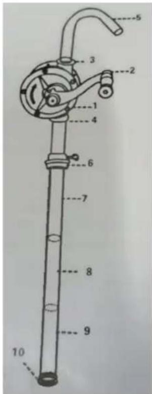
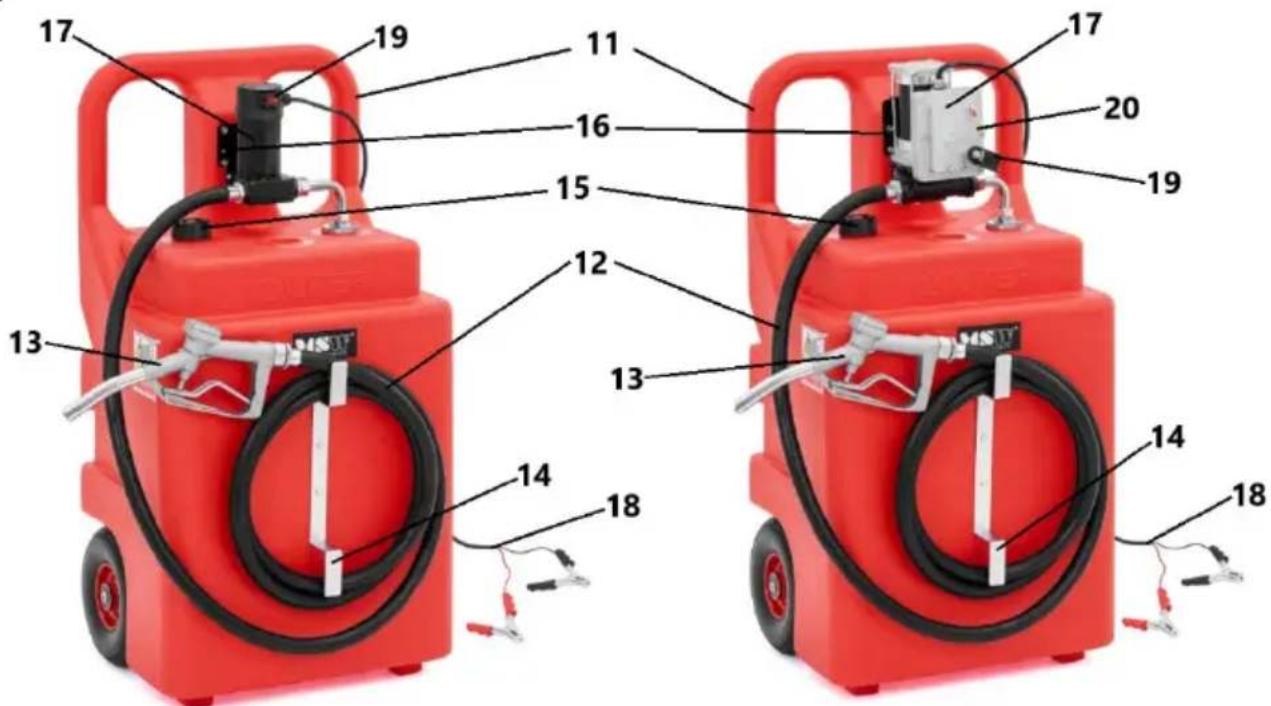
3.1. Product overview
MSW-PFT-120-M
Pump:
-
Pump casing
-
Crank
-
Pump outlet opening
- Pump suction opening
- Outlet pipe-bend for the hose
- Adapter for the tank opening
- Suction pipe with internal thread
- Suction pipe with external thread
- Suction pipe with male and female thread
- Foot with filter
Device:
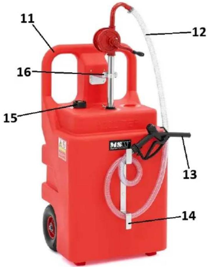
- Transport handle
- Hose
- Refueling gun
- Hose holder
- Tank vent
- Pump handle
MSW-PFT-120-D / MSW-PFT-120-P

- Transport handle
- Hose
- Refueling gun
- Hose holder
- Tank vent
- Pump handle
- Electric pump
- Power cord with battery clamps
- Pump on/off switch
- Earthing cable
3.2. Preparation for operation
POSITIONING OF THE UNIT
The ambient temperature must not exceed 45^ and ambient humidity should not exceed 90% . Use the unit in properly ventilated spaces. Keep the device away from any hot surfaces, sources of sparks or fire. Always operate the unit on a level, stable, clean, fireproof surface and out of the reach of children and persons with impaired mental, sensory, and intellectual functions. The working place of the device should provide unrestricted access to the trigger of the gun.
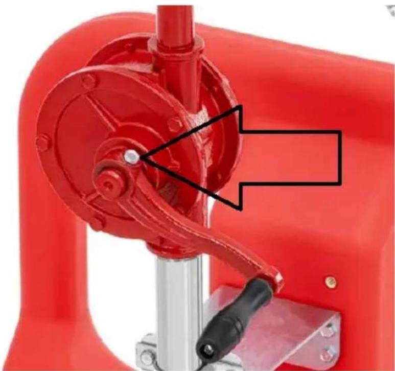
ASSEMBLY (MSW-PFT-120-M)
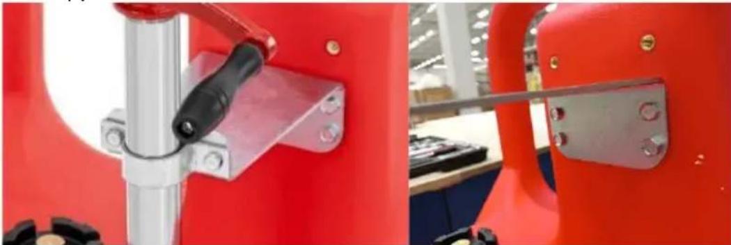
The first step is to assemble the pump. To do this, loosen the crank fixing screw (see the following photo) and fix the crank on the pump body stem, then tighten the fixing screw so that the crank moves freely.
natural_image
Close-up of a red industrial machine with a black handle and mechanical components (no visible text or symbols)In the next step, we assemble the suction pipe from 3 pieces (see paragraph description of the device - pump), remembering to attach an adapter on one segment to the entrance hole to the tank. At the very end of the suction pipe, screw the foot with the filter. For better tightness and thus suction power, it is recommended to use Teflon tape on threaded pipe connections. Place the pump thus assembled in the tank, and attach the pump bracket to the tank bracket using the supplied screws:
natural_image
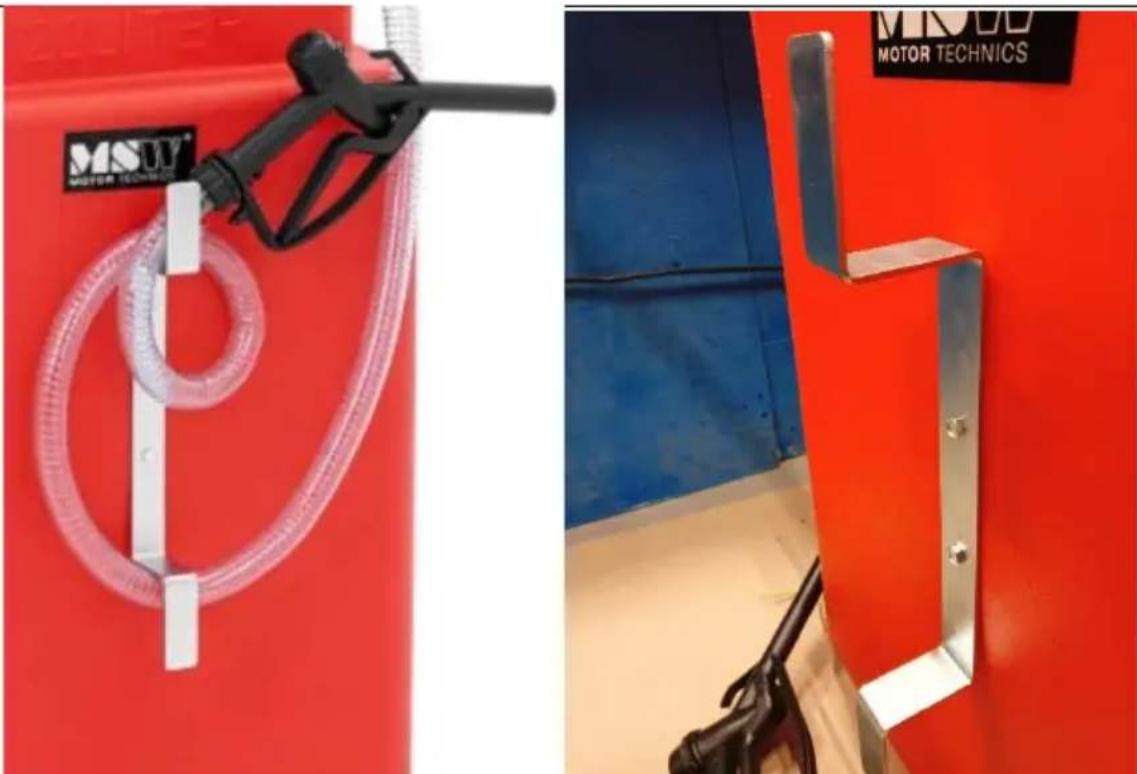
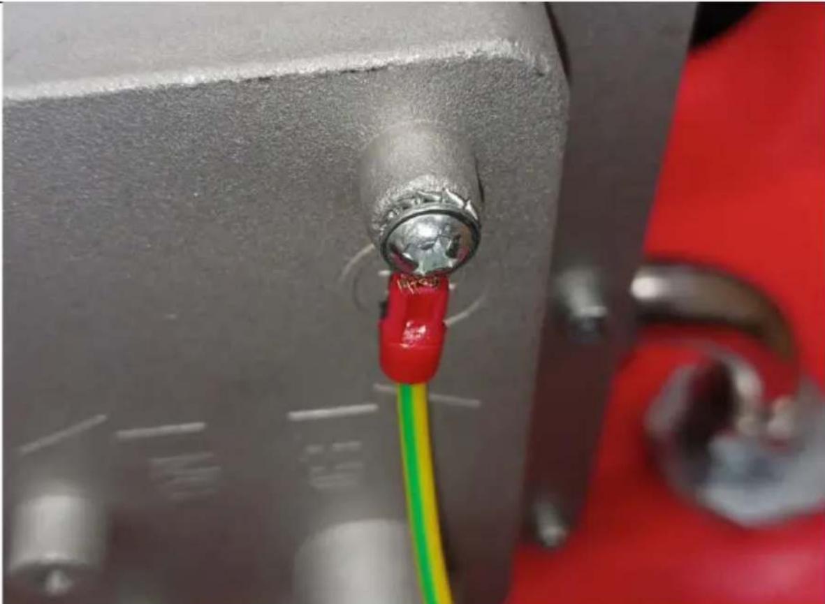
Close-up of a red industrial machine with a black tool and metal bracket, no visible text or symbolsAlso screw the supplied ground wire (yellow-green) to this bracket (screw) at the suction pipe. Next, on the front housing of the tank, screw the hose hanger with the gun.
natural_image
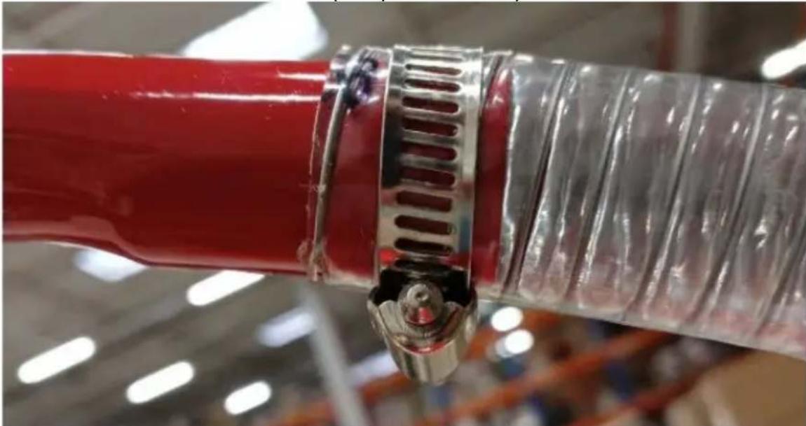
Exterior view of a red industrial gas pump with attached motor technology hose (no signage)Attach the adapter-hose outlet bend to the outlet hole in the pump body. At the other end of this elbow, fix one end of the hose (use a worm clamp for this), while at the other end of the hose fix the gun. Also at this end of the hose, use a worm band to secure the connection (see photo below).
natural_image
Close-up of a red cylindrical object with metallic clamps and a metallic hose, no visible text or symbols.ASSEMBLY (MSW-PFT-120-D / MSW-PFT-120-P)
Screw the supplied ground wire (yellow-green; if available) to the pump holding bracket (screw):
natural_image
Close-up of a metallic connector with red and green wires, mounted on a gray industrial panel (no visible text or symbols)Next, on the front housing of the tank, screw the hose hanger:
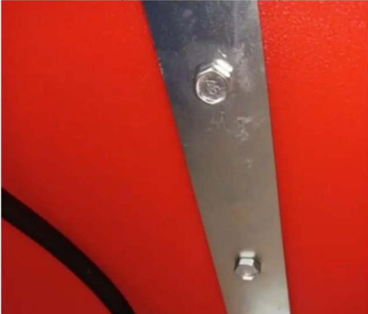
natural_image
Close-up of a metallic metal bracket with two bolts, set against a red background (no text or symbols visible)Install the reinforced hose – on end in the pump inlet, the other one connect with the refilling pistole:
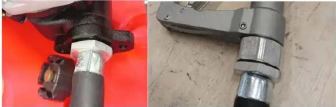
natural_image
Close-up of mechanical components with no visible text or symbolsConnect the battery clamp to an 12V car or motorcycle battery – red clamp to a positive pole, black clamp to a negative.
3.3. Working with the device
Manual pump:
Before each use, first prime the pump. To do this, you need to:
- Remove the outlet hose from the pump body and turn the crank.
- Pour a small amount of fluid (which will be pumped) inside the pump body and fix the outlet bend back on it.
- Once everything is attached, turn the crank in the direction marked by the arrow on the body to pump the fluid.
- The pump should be primed and you can already start pumping fluid from the tank.
Electrical pump should prime itself. To turn on the pump put the on/off switch to on-position. Avoid to run the pump longer than 30 minutes.
3.4. Cleaning and maintenance
a) Use only non-corrosive cleaning agents for cleaning the surfaces.
b) It is recommended to clean the device after each use with a suitable agent that dissolves the residue of the pumped liquid. Cleaning is necessary before pumping a different fluid than the previous time.
c) After each cleaning, all the parts should be dried well before the unit is used again.
d) Store the unit in a dry and cool place protected from moisture and direct sunlight. Before prolonged non-use, lubricate the pumping mechanism.
e) Do not spray the unit with a stream of water or immerse it in water.
f) Use a soft cloth for cleaning.
g) For maintenance, spray the pump body with Teflon grease.
h) Do not use sharp and/or metal objects (e.g. wire brush or metal spatula) for cleaning as they may damage the surface of the appliance material.

UWAGA! The figures in this manual are illustrative only and may vary in some details from the actual appearance of the product.
MSW-PFT-120-D / MSW-PFT-120-P

MONTAŻ (MSW-PFT-120-M)
natural_image
Close-up of a red industrial machine with a black tool inserted, showing mechanical components and a blue arrow indicating a section (no text or symbols present)natural_image
Close-up of a red industrial machine with a black handle and metal frame, no visible text or symbolsnatural_image
Two red industrial equipment components: a motor pump with a transparent hose and a blue panel, both without visible text or symbols.natural_image
Close-up of a red fire hydrant with metallic tubing and a metal clip, no visible text or symbolsMONTAŻ (MSW-PFT-120-D / MSW-PFT-120-P)
natural_image
Close-up of a metallic connector with red and green wires, mounted on a gray industrial panel (no visible text or symbols)natural_image
Close-up of a metallic metal bracket with two bolts, set against a red background (no text or symbols visible)natural_image
Close-up of mechanical components with metallic fittings and connectors, one mounted on a red surface (no visible text or symbols)MSW-PFT-120-D / MSW-PFT-120-P

MONTÁŽ (MSW-PFT-120-M)
natural_image
Close-up of a red industrial machine with a black arrow pointing to a mechanical component (no visible text or symbols)natural_image
Close-up of a red industrial machine with a black handle and metal frame, no visible text or symbolsnatural_image
Exterior view of a red industrial gas pump with attached motor technology hose (no signage)natural_image
Close-up of a red cylindrical object with metallic clamps and a metallic handle, no visible text or symbols.MONTÁŽ (MSW-PFT-120-D / MSW-PFT-120-P)
natural_image
Close-up of a metallic connector with red and green wires, mounted on a gray industrial panel (no visible text or symbols)natural_image
Close-up of a metallic metal bracket with two bolts, set against a solid red background (no text or symbols visible)natural_image
Close-up of mechanical components with no visible text or symbolsMSW-PFT-120-D / MSW-PFT-120-P
ASSEMBLAGE (MSW-PFT-120-M)
natural_image
Close-up of a red industrial machine with a black tool inserted, showing mechanical components and a blue arrow indicating direction (no text or symbols visible)natural_image
Close-up of a red industrial machine with a black-handled lever and metal bracket (no visible text or symbols)natural_image
Exterior view of a red motor gas station with a black fuel pump and transparent hose (no signage or text visible)natural_image
Close-up of a red fire extinguisher with metallic clamps and ventilation slots (no text or symbols visible)ASSEMBLAGE (MSW-PFT-120-D / MSW-PFT-120-P)
natural_image
Close-up of a metallic connector with red and green wires, mounted on a gray industrial panel (no visible text or symbols)natural_image
Close-up of a metallic metal bracket with two bolts, set against a red background (no text or symbols visible)natural_image
Close-up of mechanical components with no visible text or symbolsModello MSW-PFT-120-D / Modello MSW-PFT-120-P

MONTAGGIO (MSW-PFT-120-M)
natural_image
Close-up of a red industrial machine with a black tool inserted, showing mechanical components and a blue arrow indicating direction (no text or symbols visible)natural_image
Close-up of a red industrial machine with a black-handled lever and metal bracket (no visible text or symbols)natural_image
Two red industrial equipment components: a motor pump nozzle and a blue safety cabinet with metal fittings (no visible text or symbols)natural_image
Close-up of a red fire hydrant with metallic clamps and ventilation slots, no visible text or symbolsMONTAGGIO (MSW-PFT-120-D / MSW-PFT-120-P)
natural_image
Close-up of a metallic electrical connector with red and green wires, mounted on a gray wall (no visible text or symbols)natural_image
Close-up of a metallic metal bracket with two bolts, set against a red background (no text or symbols visible)natural_image
Close-up of mechanical components with no visible text or symbolsMSW-PFT-120-D / MSW-PFT-120-P

MONTAJE (MSW-PFT-120-M)
natural_image
Close-up of a red industrial machine with a black tool inserted, showing mechanical components and a blue arrow indicating direction (no text or symbols visible)natural_image
Close-up of a red industrial machine with a black-handled lever and metal bracket (no visible text or symbols)natural_image
Exterior view of a red motor gas station with a black fuel pump and transparent hose (no signage or text visible)natural_image
Close-up of a red fire hydrant with metallic clamps and ventilation slots, no visible text or symbolsCONJUNTO (MSW-PFT-120-D / MSW-PFT-120-P)
natural_image
Close-up of a metallic electrical connector with red and green wires, no visible text or symbolsnatural_image
Close-up of a metallic metal bracket with two bolts, set against a red background (no text or symbols visible)natural_image
Close-up of mechanical components on a red surface, one showing a metallic pipe fitting and the other a gray tool handle (no visible text or symbols)MSW-PFT-120-D / MSW-PFT-120-P

natural_image
Close-up of a red industrial machine with a black tool inserted, showing mechanical components and a blue arrow indicating a section (no text or symbols visible)natural_image
Close-up of a red industrial machine with a black tool and metal bracket, no visible text or symbolsnatural_image
Exterior view of a red industrial machine with a motor fuel nozzle and attached blue panel (no visible text or symbols)natural_image
Close-up of a red cylindrical object with metallic clamps and a metallic handle, no visible text or symbols.SZERELVÉNY (MSW-PFT-120-D / MSW-PFT-120-P)
natural_image
Close-up of a metallic connector with red and green wires, mounted on a gray industrial panel (no visible text or symbols)natural_image
Close-up of a metallic metal bracket with two bolts, set against a red background (no text or symbols visible)natural_image
Close-up of mechanical components with no visible text or symbolsMSW-PFT-120-D / MSW-PFT-120-P

APPARATETS PLACERING
SAMLING (MSW-PFT-120-M)
natural_image
Close-up of a red industrial machine with a black handle and mechanical components (no visible text or symbols)natural_image
Close-up of a red industrial machine tool with a black handle and metal bracket, no visible text or symbolsnatural_image
Red industrial machine with a black fuel pump and transparent hose, next to a blue safety panel (no visible text or symbols)natural_image
Close-up of a red cylindrical object with metallic tubing and a metal clip, no visible text or symbolsSAMLING (MSW-PFT-120-D / MSW-PFT-120-P)
natural_image
Close-up of a metallic connector with red and green wires, mounted on a gray industrial panel (no visible text or symbols)natural_image
Close-up of a metallic metal bracket with two bolts, set against a red background (no text or symbols visible)natural_image
Close-up of mechanical components with no visible text or symbolsMSW-PFT-120-D / MSW-PFT-120-P

natural_image
Close-up of a red industrial machine with a black tool inserted, showing mechanical components and a blue arrow indicating a section (no text or symbols visible)natural_image
Close-up of a red industrial machine with a black handle and metal frame, no visible text or symbolsnatural_image
Exterior view of a red industrial machine with a motor fuel nozzle and a blue safety panel (no visible text or symbols)natural_image
Close-up of a red cylindrical object with metallic clamps and a metallic handle, no visible text or symbols.KOKOONPANO (MSW-PFT-120-D / MSW-PFT-120-P)
natural_image
Close-up of a metallic connector with red and green wires, mounted on a gray industrial panel (no visible text or symbols)natural_image
Close-up of a metallic metal bracket with two bolts, set against a red background (no text or symbols visible)natural_image
Close-up of mechanical components on a red surface, one showing a metallic pipe fitting and the other a gray tool (no visible text or symbols)MSW-PFT-120-D / MSW-PFT-120-P