SC05IB00TE - Dishwasher SIEMENS - Free user manual and instructions

Find the device manual for free SC05IB00TE SIEMENS in PDF.
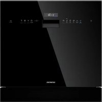
SIEMENS SC05IB00TE - Dishwasher
📄 801 pages English EN Download 💬 AI Question 10 questions ⚙️ Specs
Notice SIEMENS SC05IB00TE - page 173
Pick your language and provide your email: we'll send you a specifically translated version.
Product typeDishwasher
BrandSiemens
ModelSC05IB00TE
Width (cm)60
Height (cm)81.5
Depth (cm)57.5
Weight (kg)45
Voltage (V)220-240
Frequency (Hz)50
Installation typeBuilt-in
Number of baskets2
Spray armsUpper and lower removable
FiltersMulti-filter system with coarse filter and microfilter
LightingEmotion Light (LED)
Control panelRemovable for repair
Door gasketRemovable, replaceable
Drain pumpCover accessible after removing filters
Door springsTwo tension springs, non-adjustable
Spare partsArms, filters, gaskets, pump cover, plug, hinges, Emotion Light
SafetyDisconnect the appliance 60 s before repair; wear protective gloves

Frequently Asked Questions - SC05IB00TE SIEMENS

How to replace the upper spray arm?
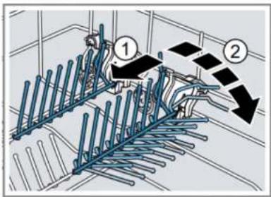
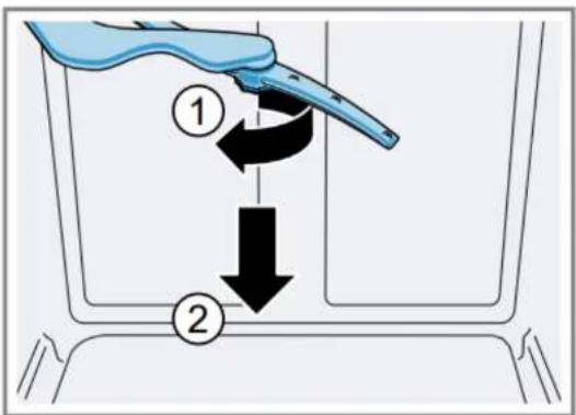
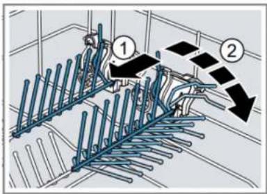
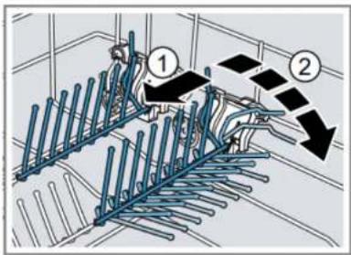
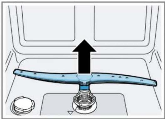
Unscrew the upper spray arm (1), lower the arm (2), then remove. For installation, insert and screw firmly.
How to clean the filters?
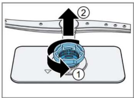
Turn the coarse filter counterclockwise, remove the filter system, lower the microfilter and press the tabs to lift the coarse filter. Clean under running water.
What to do if the door does not open or close properly?
Check the door springs and hinges. The springs are not adjustable, but can be replaced. See section 4.12 of the manual.
How to replace the drain pump cover?
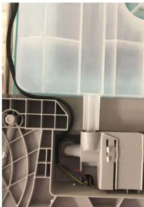
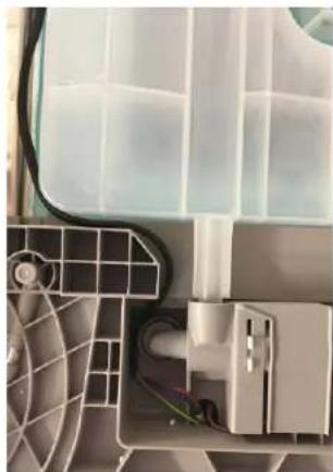
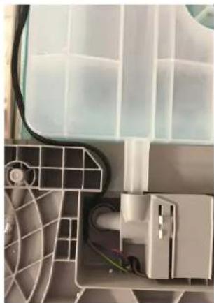
Unplug the appliance, remove the baskets and filters, drain residual water. Unscrew the Torx T20 screws, lift the cover, remove debris, then reverse the steps.
Is it possible to replace the power plug?
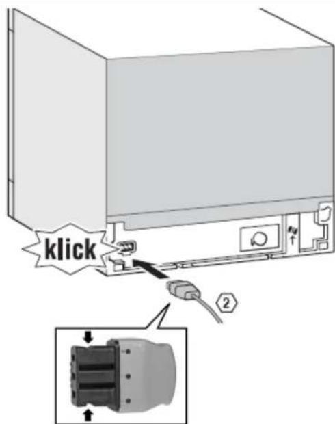
Yes, the plug is removable. Gently pull sideways while pulling to unlock it. When installing, insert until it clicks. Pay attention to the voltage and frequency of the country.
How to remove the outer door?
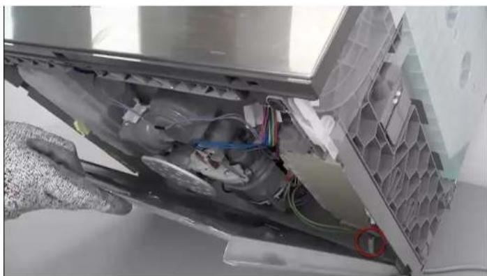
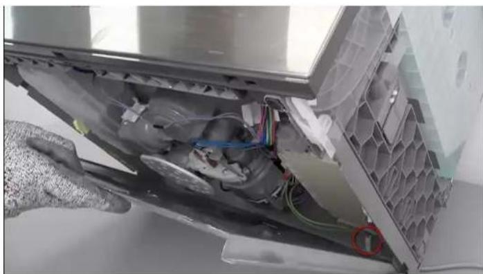
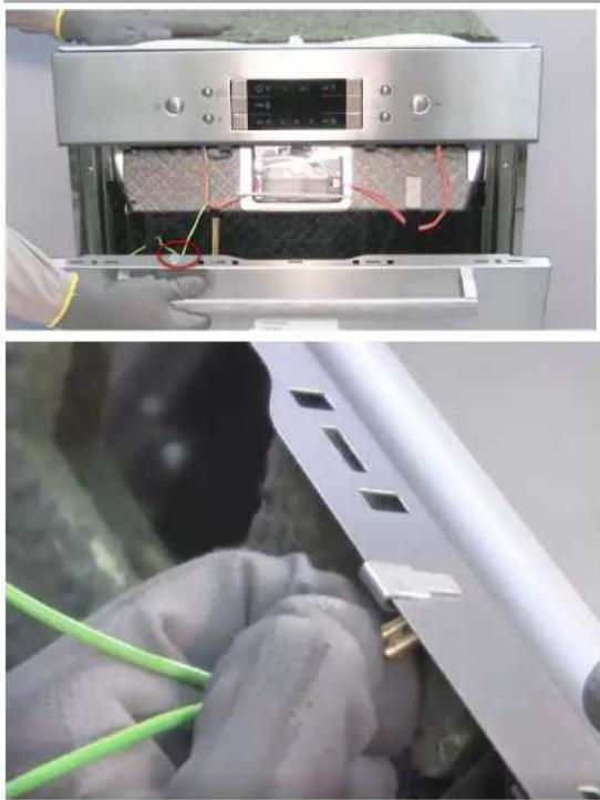
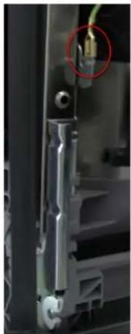
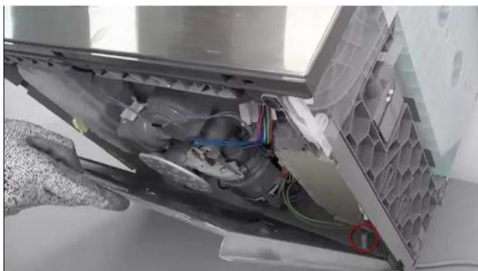
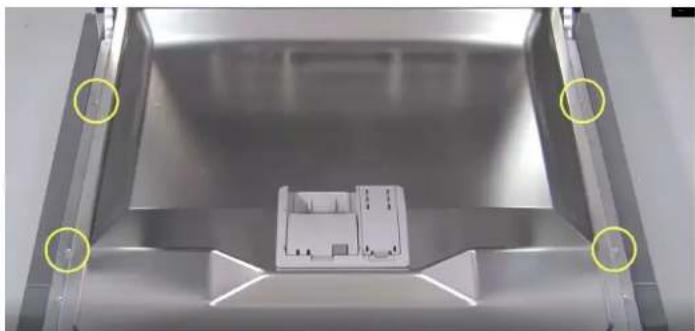
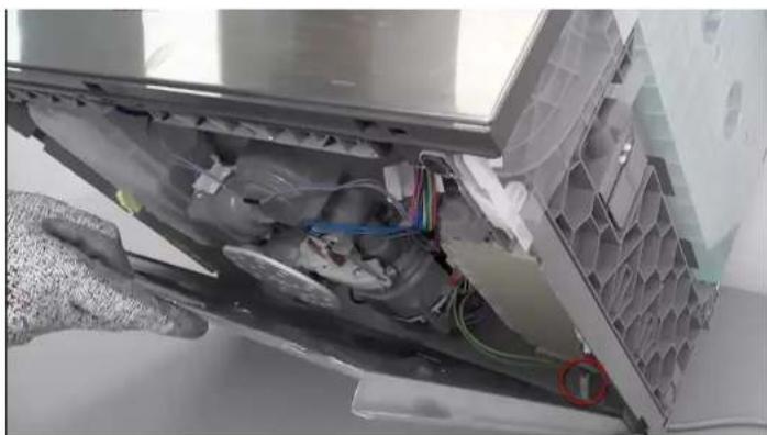
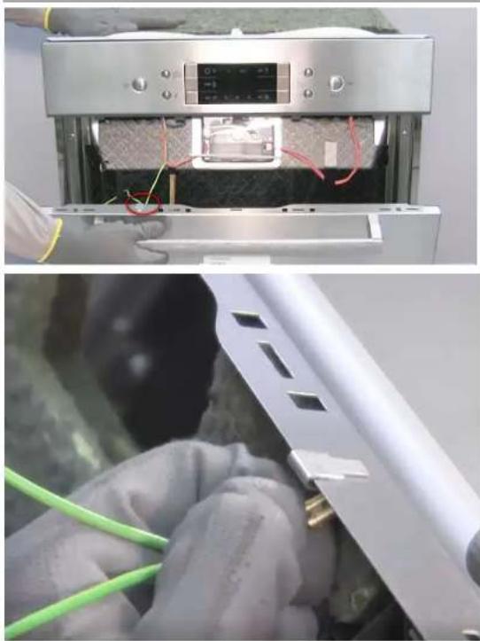
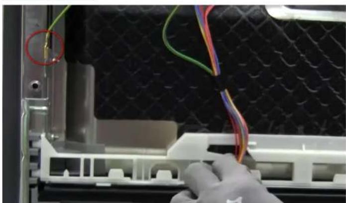
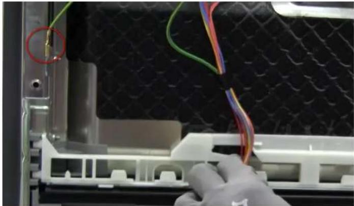
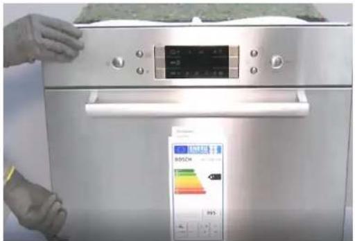
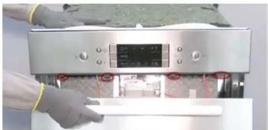
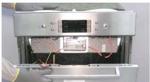
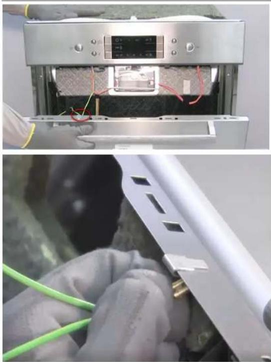
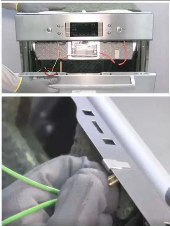
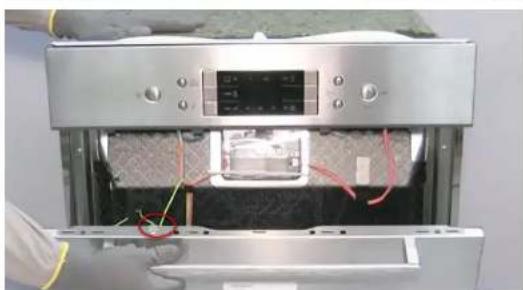
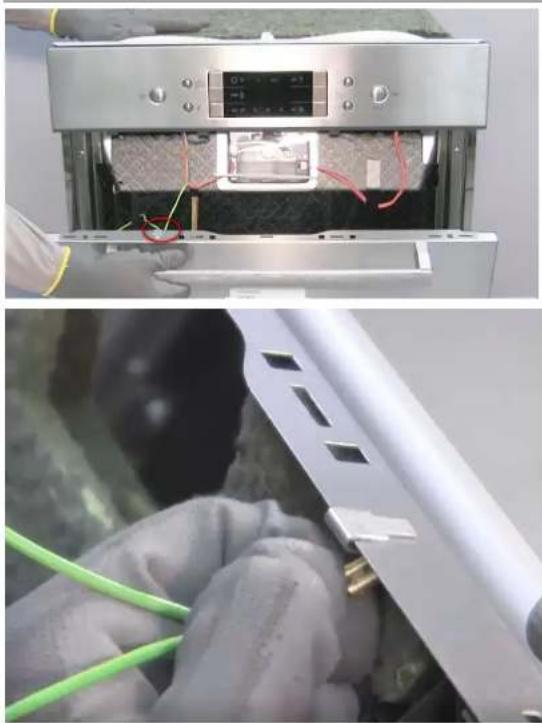
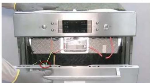
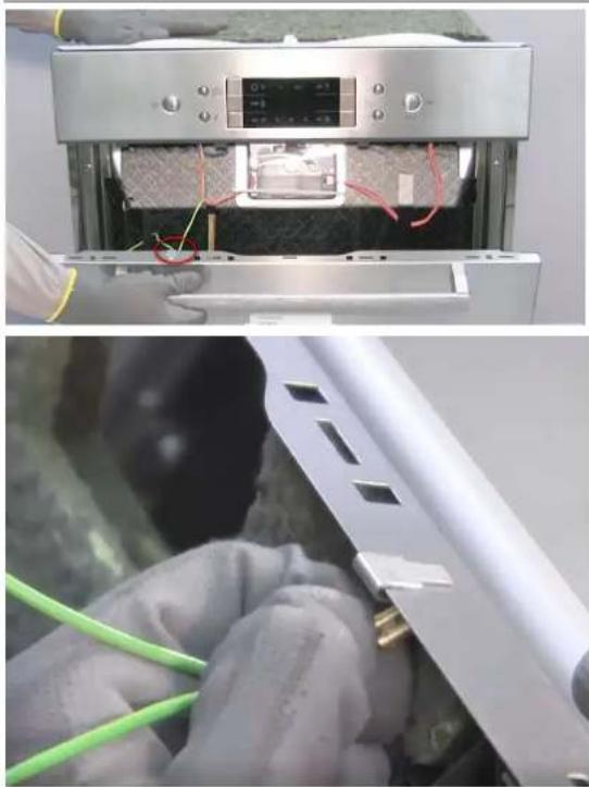
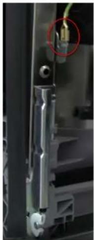
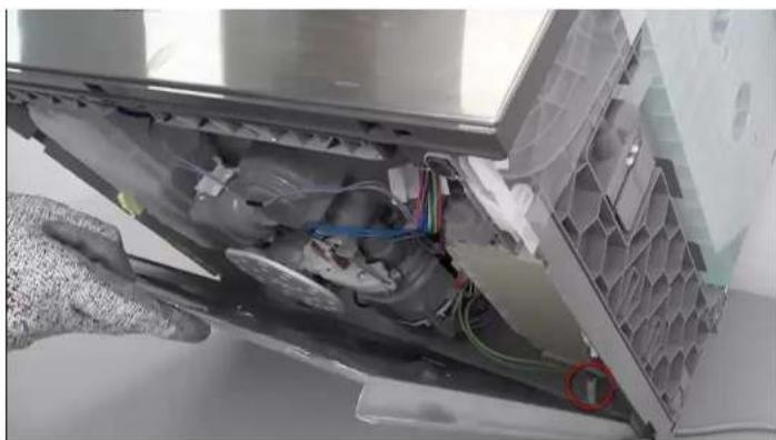
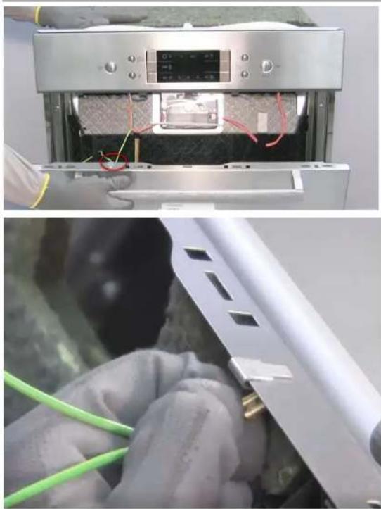
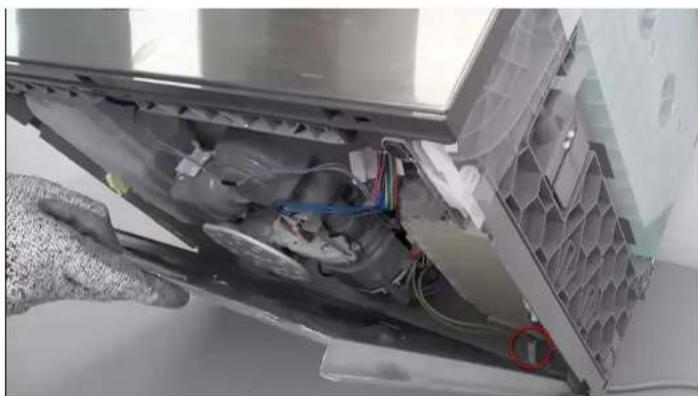
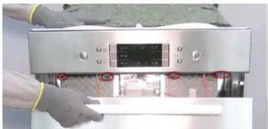
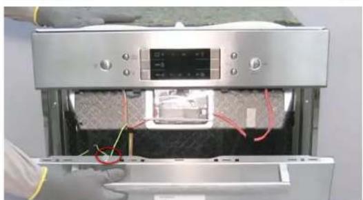
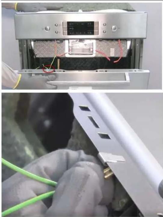
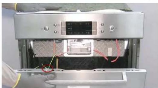
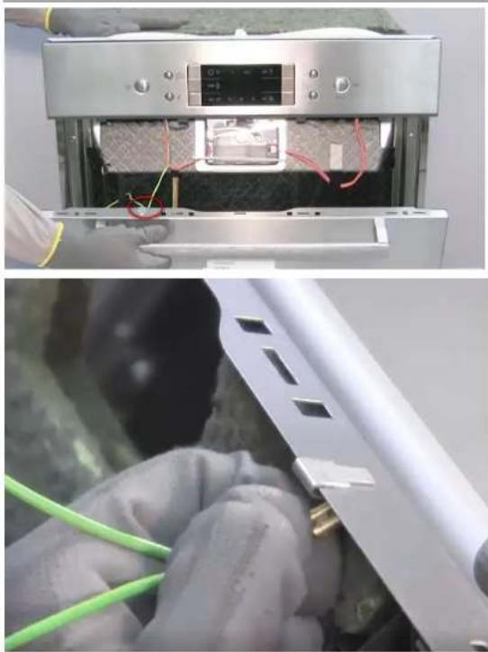
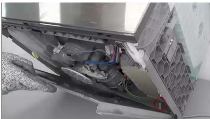
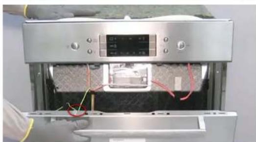
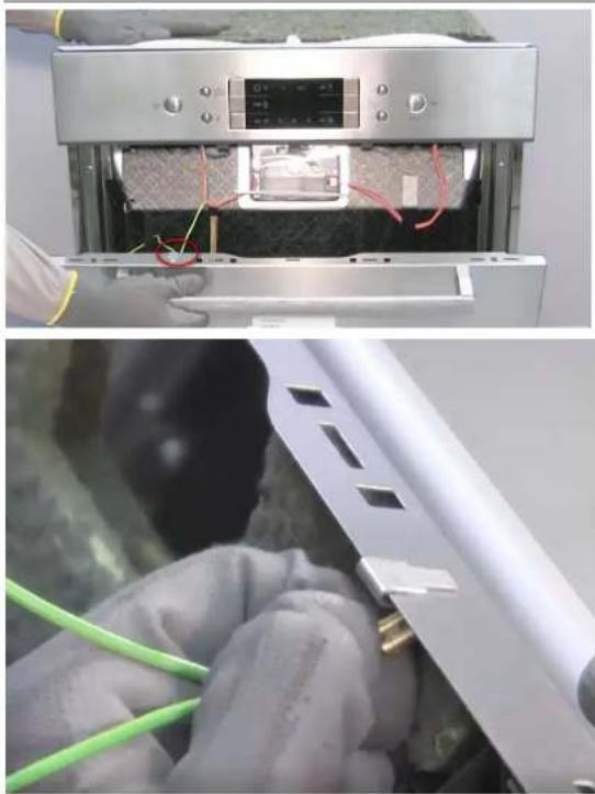
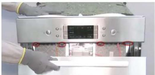
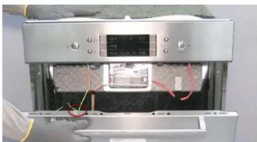
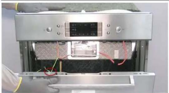
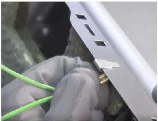
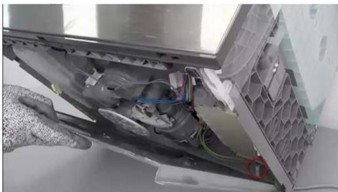
Unplug the appliance and shut off the water supply. Open the door, remove 4 Torx 20 screws, close the door while holding it, lower the latches, disconnect the ground cable.
What tools are needed for repairs?
Torx T15 and T20 screwdrivers with hole, flathead screwdriver (200 mm), needle-nose pliers (200 mm).
How to replace the lower door gasket?
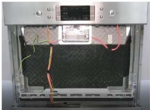
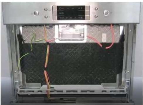
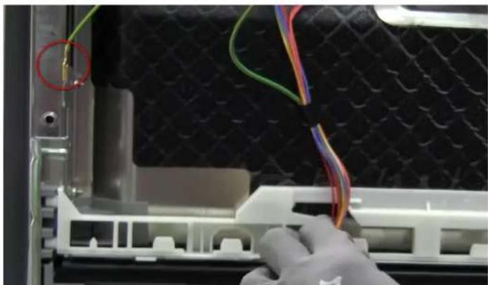
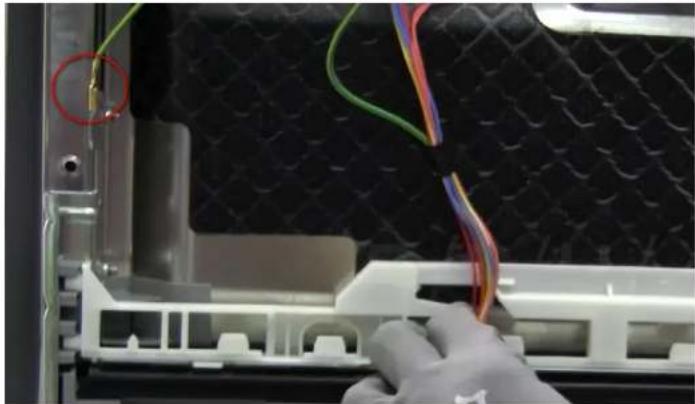
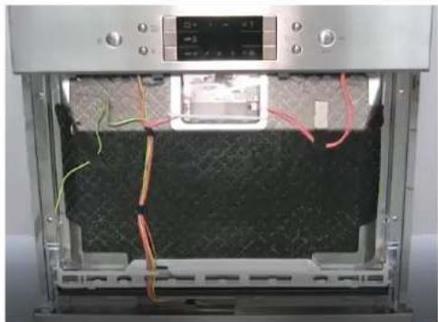
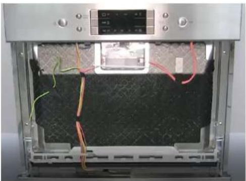
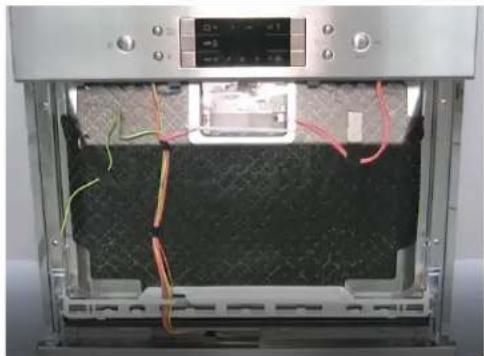
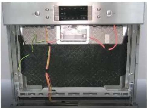
Remove the outer door, remove the cable harness from the white guide, detach the gasket from the base, then install the new gasket by pressing on the base. Ensure the gasket is flush.
Can I replace the Emotion Light myself?
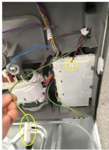
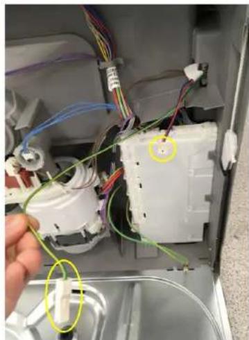
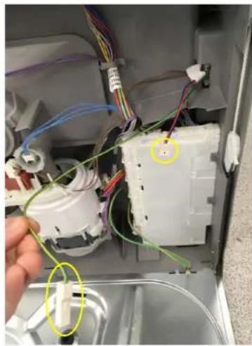
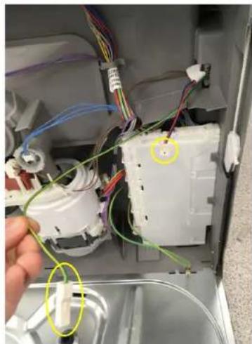
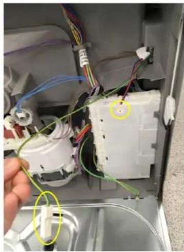
Yes, after unplugging the appliance and removing the lower base. Disconnect the connectors of the power module and ground, release the latch and pull the lights upward.
What are the essential safety instructions?
Unplug the appliance at least 60 seconds before any repair. Wear protective gloves. Use only original parts. After repair, perform a test according to VDE 0701.

User questions about SC05IB00TE SIEMENS

0 question about this device. Answer the ones you know or ask your own.

Ask a new question about this device

Your email remains private: it is only used to notify you if someone answers your question.

No questions yet. Be the first to ask one.

Download the instructions for your Dishwasher in PDF format for free! Find your manual SC05IB00TE - SIEMENS and take your electronic device back in hand. On this page are published all the documents necessary for the use of your device. SC05IB00TE by SIEMENS.

USER MANUAL SC05IB00TE SIEMENS

[sv] Reparationsinformation....736

4 PEMOHT ....
Technical diagram showing a mechanical assembly with labeled components and directional arrows indicating motion or flow.

Interior view of a stainless steel kitchen appliance with a hand adjusting the door (no visible text or symbols)

Person using a digital kitchen machine with control panel and paper strip (no visible text or symbols)

Interior view of a stainless steel appliance with visible wiring and control panel (no text or symbols).

Two-panel image showing a device interior with wiring and a close-up of hands installing or maintaining components (no visible text or symbols).

Interior view of a 3D printer oven with visible wiring and control panel (no text or symbols).

SIEMENS SC05IB00TE - PEMOHT .... - 7

Panel screws

4.9.2 Assembly
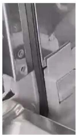
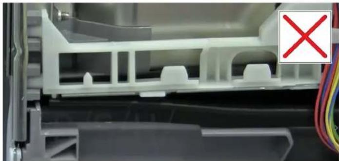
Close-up of a white plastic electronic component with a red X symbol, no visible text or symbols on the main structure.

Technical diagram showing mechanical assembly steps with magnified views highlighting structural changes and red arrows indicating motion direction.

Diagram showing three different corner joint configurations with checkmark indicators and red X marks indicating failure or rejection status.

Technical diagram showing two views of a pipe bend with checkmark and cross symbols indicating inspection or failure.

Close-up of a metallic door with glass panels and a black handle (no visible text or symbols).

Close-up of a mechanical component with a star-shaped emblem and number 20, no readable text or symbols present.

Close-up of a mechanical component with a star-shaped icon labeled '20' (no readable text or symbols beyond the number).

Close-up of a Siemens air conditioner unit with a cloth partially visible, no text or symbols on the device itself.

Close-up of a silver computer drive casing with a hand adjusting its top panel (no visible text or symbols).

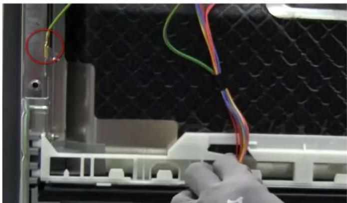
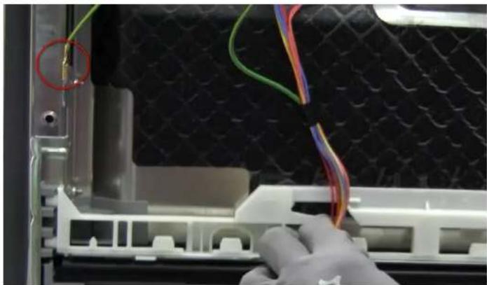
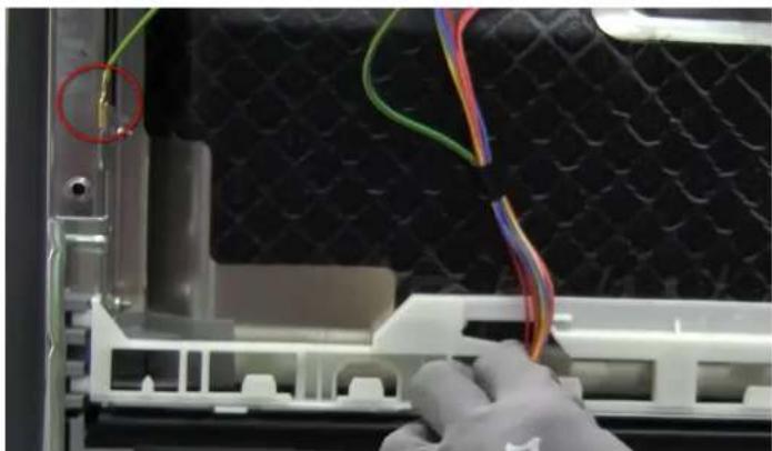
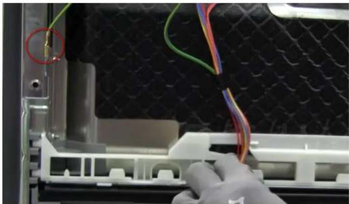
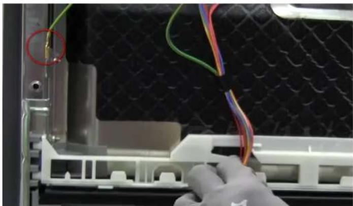
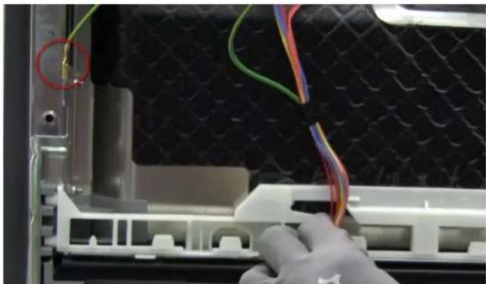
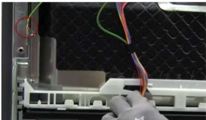
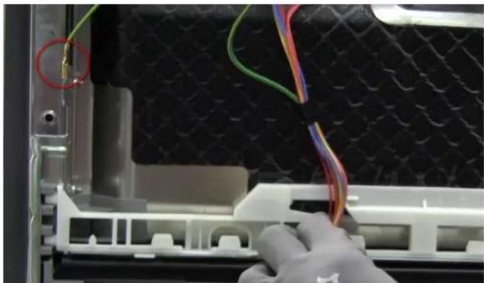
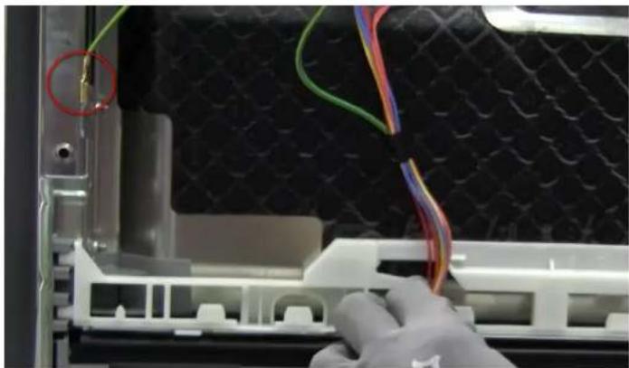
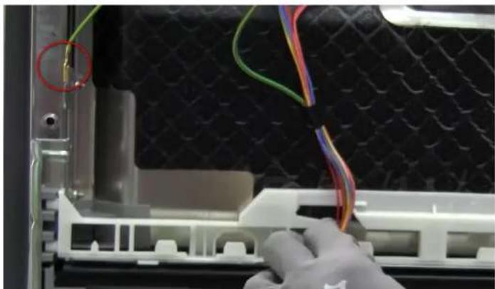
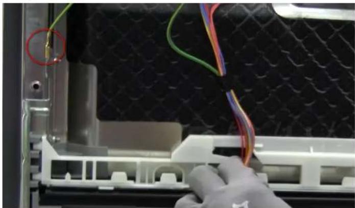
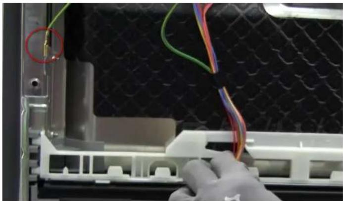
Close-up of a mechanical device showing internal components with a green cable and a red circle highlighting a small green component (no text or symbols visible).

Close-up of an air conditioner unit showing internal components and wiring (no text or symbols visible).

4.11.2 Assembly

4.12.2 Assembly

1 Roller

2 Rope

3 Plastic holder

Close-up of a mechanical component with a red circle highlighting a small connector (no visible text or symbols).

Close-up of a gloved hand adjusting a 3D printer's cable and plastic component (no visible text or symbols).

Close-up of a gloved hand holding a white plastic device with colorful wires and a red circle highlighting a component (no visible text or symbols).

Interior view of an appliance showing wiring and components, with a hand holding a cable (no visible text or symbols).

Close-up of an air conditioner fan assembly with visible wiring and cooling unit (no text or symbols).

Close-up of a mechanical device showing internal components and wiring, with no visible text or symbols.

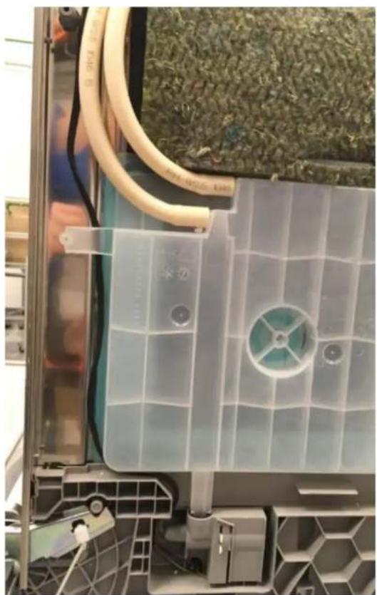
Close-up of a metallic industrial device with beige hoses and connectors, placed on grass (no visible text or symbols).

3D mechanical assembly diagram showing a component inserted into a bracket with mounting holes (no text or symbols visible).

Close-up of a metallic mechanical bracket with attached white connectors and wires, placed on grass (no visible text or symbols).

Interior view of a stainless steel enclosure with visible wiring and connectors (no text or symbols).

Interior view of a cleanroom or industrial space with plastic partitions and ventilation ducts (no visible text or symbols)

REPAIR MANUAL

GV550 BI60-BI45

1 INTRODUCTION....

1.1 Purpose of the document....

1.2 General symbols....

1.3 Relevant safety symbols......

2 SAFETY......

4 REPAIR......

4.1 Replacing the spray arms......

4.2 Replacing the filters......

4.3 Replacing the drain pump cover......

4.4 Replacing the plug....

4.5 Basket systems....

4.6 Replacing the outer door....

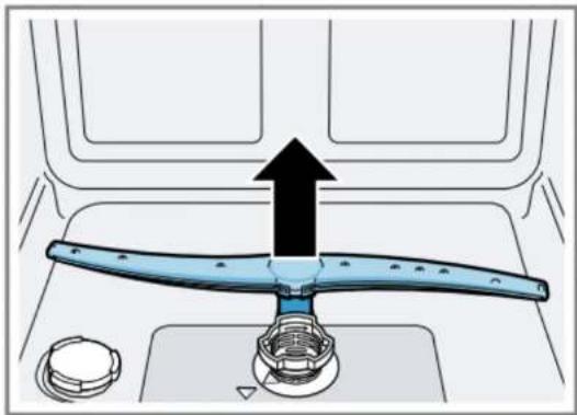
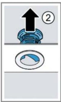
Push the lower spray arm upwards.

Diagram of a kitchen appliance with a blue handle and black upward arrow indicating motion (no text or symbols)

4.1.2 Installing the spray arm

Insert the lower spray arm. You will hear a click when it snaps into place. Insert the upper spray arm and secure it well.

4.2 Replacing the filters

4.2.1 Removing the filters

Press the release tabs (1) and pull the coarse filter upwards (2).

Technical diagram showing mechanical assembly steps with numbered instructions and directional arrows

4.2.2 Installing the filters

  1. Reinstall the filter system. Make sure the locking elements on the coarse filter fit into place.
  2. Insert the filter system into the appliance and turn the coarse filter clockwise.

4.3 Replacing the drain pump cover

Prerequisites:

Pull the pump cover upwards.

Mechanical assembly diagram showing a blue clamp bracket inserted into a component (no text or symbols visible)

Remove food residues and foreign objects from the interior of the appliance.

Technical diagram showing a mechanical assembly with labeled components and directional arrows indicating motion or flow.

Interior view of a stainless steel kitchen appliance with a hand adjusting the door. No visible text or symbols.

Close-up of a gloved hand pressing down on a stainless steel appliance with control buttons and a white strip. No visible text or symbols.

Interior view of a stainless steel appliance with visible wiring and a digital display. No text or symbols.

Two-panel image showing a device interior with wiring and a close-up of hands installing or maintaining components. No visible text or symbols.

Interior view of a 3D printer oven with visible wiring and control panel. No text or symbols.

SIEMENS SC05IB00TE - Prerequisites: - 8

Screws for the plate

Interior view of a stainless steel appliance with visible wiring and control panel. No text or symbols.

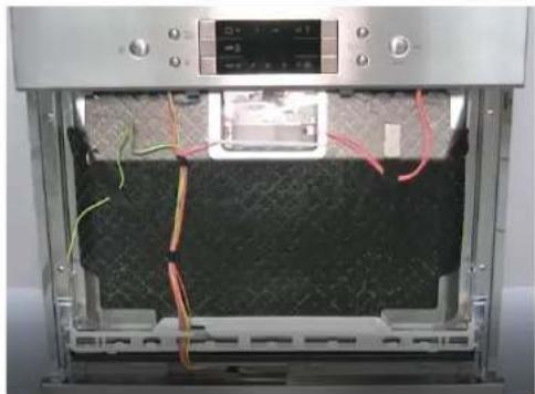
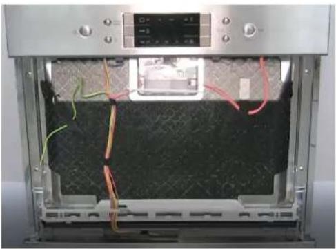
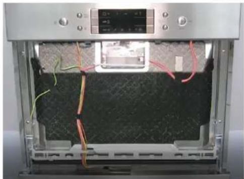
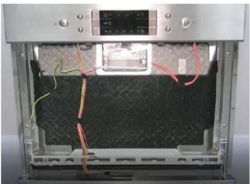
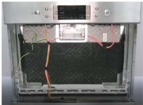
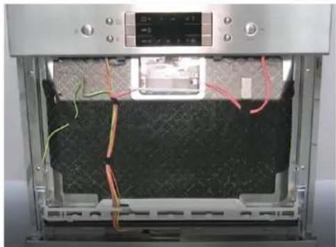
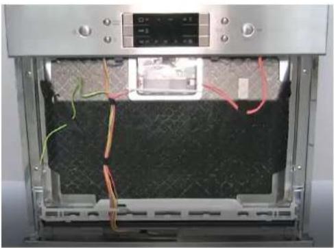
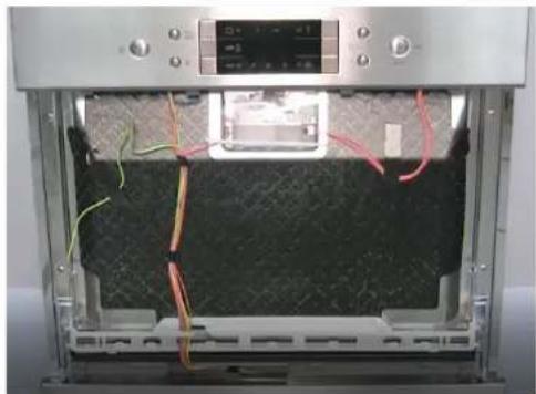
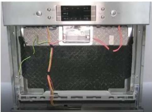
Correctly position the cable harness in the lower seal support.

4.7.2 Install the control panel.

Remove it from the lower attachment position.

Close-up of a mechanical component with red circles highlighting specific parts. No visible text or symbols.

Pull it upwards to detach it from the base.

Close-up of a gloved hand installing or adjusting a white plastic component on a mechanical device. No visible text or symbols.

4.9.2 Assembly

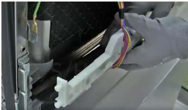
Insert the cable harness into the white support.

Close-up of hands connecting a white plastic component with red and yellow wires. No visible text or symbols.

Technical diagram showing mechanical assembly steps with magnified views highlighting structural changes and red arrows indicating motion direction.

Diagram showing three stages of a vehicle door with checkmark and red X marks indicating failure or rejection status.

Technical diagram showing two views of a pipe bend with checkmark and cross symbols indicating inspection or failure.

Close-up of a metallic door with glass panels and a black handle. No visible text or symbols.

Close-up of a mechanical component with a star-shaped badge labeled '20'. No readable text or symbols beyond the badge.

Close-up of a mechanical component with a star-shaped icon labeled '20'. No readable text or symbols beyond the number.

Close-up of a Siemens air conditioner unit with a cloth partially visible. No text or symbols on the device itself.

Close-up of a silver computer drive casing with a hand adjusting its top panel. No visible text or symbols.

Close-up of a mechanical device showing wiring and a green cable, with a red circle highlighting a small component. No visible text or symbols.

Interior view of a refrigerator showing internal components and wiring. No visible text or symbols.

4.11.2 Assembly

1 Position the bottom cover by inserting the protruding edges into the slots on the plastic tub base. 2 Place the grounding wire in the base. 3 Screw in the two fastening screws.

4.12 Replacing the door springs

Prerequisite

The device is disconnected from the power supply.

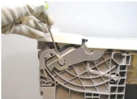
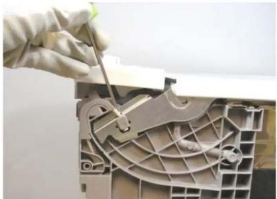
  1. Use a screwdriver to detach the rope from the hinge.
  2. After detaching the rope, the spring can be removed.

Close-up of a gloved hand using a screwdriver to adjust or install a mechanical component (no visible text or symbols)

4.12.2 Assembly

Assemble in reverse order.

SIEMENS SC05IB00TE - Assembly - 1

Holder

1 Reel

2 Rope

3 Plastic holder

4 Tension spring

4.13 Replacing the hinge

Prerequisites:

The device is disconnected from the power supply.

Close-up of a mechanical component with a red circle highlighting a small connector (no visible text or symbols)

Close-up of a gloved hand adjusting a 3D printer's cable and plastic component (no visible text or symbols)

4.13.2 Setting the joint

SIEMENS SC05IB00TE - Setting the joint - 1

SIEMENS SC05IB00TE - Setting the joint - 2

DANGER

Close-up of a gloved hand inserting wires into a 3D printer casing (no visible text or symbols)

Interior view of an open refrigerator showing wiring and components (no visible text or symbols)

Close-up of an air conditioner unit showing internal components like fan, vent, and cooling unit (no text or symbols visible)

Close-up of a mechanical device showing internal components and wiring, with no visible text or symbols.

Close-up of a mechanical device with beige hoses and connectors, placed on grass (no visible text or symbols)

Close-up of a mechanical assembly with white plastic components and a beige pipe, resting on green textured ground (no visible text or symbols)

3D mechanical assembly diagram showing a component mounted on a rail with mounting holes (no text or symbols visible)

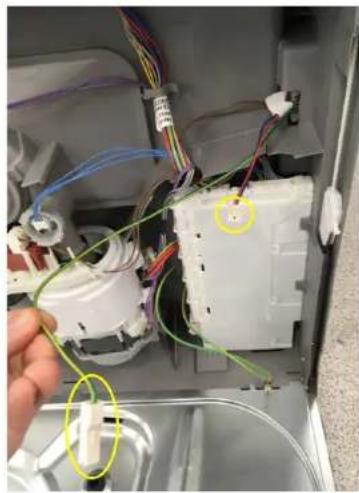
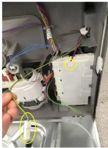
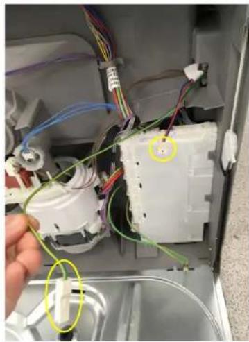
Interior view of a stainless steel enclosure with visible wiring and two yellow-circled points of interest (no text or symbols)

4.14.2 Setting the Emotion light

Follow the previous steps in reverse order, making sure the cables are laid correctly.

Interior view of a compact air conditioner unit with visible cooling fans and ventilation duct.

Interior view of a cleanroom or industrial space with plastic partitions and ventilation ducts.

REPAIR INSTRUCTIONS

GV550 BI60-BI45

1 INTRODUCTION......

1.1 Purpose of this document ....

4 REPAIR......

4.2.2 Mounting the filters

Technical diagram showing a mechanical assembly with labeled components and directional arrows indicating motion or flow.

Interior view of a stainless steel kitchen appliance with a hand adjusting the door. No visible text or symbols.

Person using a digital kitchen machine with control panel and paper strip. No visible text or symbols.

Interior view of a stainless steel appliance with red wiring and a digital display. No visible text or symbols.

Two-panel image showing a device interior with wiring and a close-up of hands installing or maintaining components. No visible text or symbols.

Interior view of a 3D printer oven with visible wiring and control panel. No text or symbols.

SIEMENS SC05IB00TE - Mounting the filters - 7

Panel screws

4.9.2 Mounting

Technical diagram showing mechanical assembly steps with magnified views highlighting structural changes and red arrows indicating motion direction.

Diagram showing three stages of a vehicle door with checkmark and red X marks indicating failure or rejection status.

Interior view of a computer monitor case with visible internal components and a small icon on top (no text or symbols)

Close-up of a mechanical component with a star-shaped badge labeled '20' (no readable text or symbols beyond the badge)

Close-up of a mechanical component with a star-shaped icon labeled '20' (no readable text or symbols beyond the number)

Close-up of a Siemens air conditioner unit with a cloth partially visible, no text or symbols on the device itself.

Close-up of a metallic electronic device with a hand adjusting its top panel (no visible text or symbols)

Close-up of a mechanical device showing internal components with a green cable and a red circle highlighting a small green component (no text or symbols visible)

Close-up of an air conditioner unit showing internal components and wiring (no text or symbols visible)

4.11.2 Mounting

4.12.2 Mounting

1 Pulley

2 Lanko

3 Plastic holder

4 Tension spring

4.13 Replacing hinges

Prerequisites:

Close-up of a mechanical component with a red circle highlighting a small connector (no visible text or symbols).

Close-up of a gloved hand adjusting a 3D printer's cable and plastic component (no visible text or symbols).

Close-up of a gloved hand inserting wires into a black textured device component (no visible text or symbols).

Interior view of an open appliance showing wiring and components (no visible text or symbols).

Interior view of a compact air conditioner unit showing internal components like fan, vent, and cooling unit (no text or symbols visible).

Close-up of a mechanical component with visible wiring and green material, no text or symbols present.

Close-up of a mechanical device with beige hoses and connectors, placed on grass (no visible text or symbols).

Close-up of a mechanical assembly with white plastic components and a beige pipe, resting on green textured ground (no visible text or symbols).

3D mechanical assembly diagram showing a component mounted on a rail with mounting holes (no text or symbols visible).

Interior view of a stainless steel enclosure with visible wiring and two yellow-circled points of interest (no text or symbols).

Interior view of a cleanroom or industrial space with plastic partitions and ventilation ducts (no visible text or symbols).

REPAIR MANUAL

GV550 BI60-BI45

1 INTRODUCTION......

4 REPAIR......

4.1.2 Mounting the spray arm

4.2.2 Mounting the filters

  1. Reinstall the filter system.

Make sure the coarse filter's hooks lock into place.

  1. Insert the filter system into the appliance and turn the coarse filter clockwise.

Technical diagram showing a mechanical assembly with labeled components and directional arrows indicating motion or flow.

Interior view of a stainless steel kitchen appliance with a hand adjusting the door (no visible text or symbols)

Person operating a refrigerator with digital display and red annotations (no readable text or symbols)

Interior view of a stainless steel appliance with red wiring and a digital display (no visible text or symbols)

Two-panel image showing a device interior with wiring and a close-up of hands installing or maintaining components (no visible text or symbols)

Interior view of a 3D printer oven with visible wiring and control panel (no text or symbols)

SIEMENS SC05IB00TE - Mounting the filters - 7

Panel screws

Interior view of a stainless steel kitchen appliance showing internal wiring and a control panel (no visible text or symbols)

4.7.2 Mounting the control panel

4.9.2 Mounting

Close-up of a white plastic mechanical component with a red X symbol overlay. No text or symbols on the main subject.

Technical diagram showing mechanical assembly steps with magnified views highlighting structural changes and red arrows indicating motion direction.

Diagram showing three stages of a vehicle door with checkmark and red X marks indicating failure or rejection status.

Interior view of a computer monitor case with visible internal components and a small icon on top. No text or symbols.

Close-up of a mechanical component with a star-shaped badge labeled '20'. No readable text or symbols beyond the badge.

Close-up of a mechanical component with a star-shaped icon labeled '20'. No readable text or symbols beyond the number.

Close-up of a Siemens air conditioner unit with a cloth partially visible. No text or symbols on the device itself.

Close-up of a metallic electronic device with a hand adjusting its top panel. No visible text or symbols.

Close-up of a mechanical device showing internal components with a green cable and a red circle highlighting a small green component. No text or symbols visible.

Interior view of an air conditioner unit showing internal components and wiring. No text or symbols visible.

4.11.2 Mounting

4.12.2 Mounting

Close-up of a mechanical component with a red circle highlighting a small connector.

Close-up of a gloved hand adjusting a 3D printer's cable and plastic component.

Close-up of a gloved hand inserting wires into a black textured device component.

Interior view of an open appliance showing wiring and components.

Close-up of a mechanical component with visible wiring and fan assembly.

Close-up of a mechanical component with visible wiring and green material.

Close-up of a mechanical device with beige hoses and connectors, placed on grass.

Close-up of a mechanical assembly with white plastic components and a beige pipe, resting on green textured ground.

3D mechanical assembly diagram showing a component mounted on a rail bar with mounting holes.

Interior view of a stainless steel enclosure with visible wiring and two yellow-circled points of interest.

4.14.2 Mounting the emotionLight

Interior view of a cleanroom or industrial space with plastic partitions and ventilation ducts.

REPAIR MANUAL

GV550 BI60-BI45

1 INTRODUCTION ....

4 REPAIR ....

4.1.2 Mounting the spray arm

4.2.2 Mounting the filters

Pull the pump cover upwards.

Mechanical assembly diagram showing a blue clamp bracket inserted into a component. No text or symbols visible.

Technical diagram showing a mechanical assembly with labeled components and directional arrows indicating motion or flow.

Interior view of a stainless steel kitchen appliance with a hand adjusting the door panel and a digital display showing a color scale. No visible text or symbols.

Close-up of hands operating a stainless steel appliance with control panel and battery. No visible text or symbols.

SIEMENS SC05IB00TE - Mounting the filters - 5

Close-up of hands installing or adjusting a mechanical component with green wires (no visible text or symbols).

Interior view of a stainless steel kitchen appliance showing internal wiring and a digital display (no visible text or symbols).

SIEMENS SC05IB00TE - Mounting the filters - 8

Panel screws

Interior view of a stainless steel kitchen appliance showing internal wiring and control panel (no visible text or symbols).

4.7.2 Mounting the control panel.

4.9.2 Mounting

Close-up of a white plastic electronic component with a red X symbol, no visible text or symbols on the main structure.

4.10 Replacing the door seal

Prerequisite

Technical diagram showing mechanical assembly steps with magnified views highlighting structural changes and red arrows indicating motion direction.

Diagram showing three stages of a vehicle door with checkmark and red X marks indicating success or failure.

Interior view of a computer drive bay with visible internal components and mounting bracket (no text or symbols).

Close-up of a mechanical component with a star-shaped emblem and number 20, no readable text or symbols present.

Close-up of a mechanical component with a star-shaped icon labeled '20' (no readable text or symbols beyond the number).

Close-up of a Siemens air conditioner unit with a cloth partially visible, no text or symbols on the device itself.

Close-up of a metallic electronic device with a hand adjusting its top panel (no visible text or symbols).

Close-up of a mechanical device showing internal components with a green cable and a red circle highlighting a small green component (no text or symbols visible).

Close-up of an air conditioner unit showing internal components and wiring (no text or symbols visible).

4.11.2 Assembly

4.12.2 Assembly

Close-up of a mechanical component with a red circle highlighting a small connector.

Close-up of a gloved hand adjusting a 3D printer's cable and plastic component.

Close-up of a robotic arm holding a wire with multicolored wires, partially enclosed in a mechanical component.

4.14 Replacing the Emotion Light

Interior view of a kitchen appliance showing wiring and components.

Interior view of an open refrigerator showing wiring and components.

Close-up of an air conditioner fan assembly with visible wiring and cooling unit.

Close-up of a mechanical component with visible wiring and green material.

Close-up of a mechanical device with beige hoses and connectors, placed on grass.

Close-up of a mechanical assembly with white components and a beige rod, mounted on a metal frame against a textured green surface.

3D mechanical assembly diagram showing a component mounted on a rail with mounting holes.

Interior view of an open industrial enclosure with visible wiring and a small component.

4.14.2 Installing the Emotion Light

Interior view of a cleanroom or industrial space with plastic partitions and ventilation ducts.

REPAIR MANUAL

GV550 BI60-BI45

1 INTRODUCTION ....

1.1 Purpose of the document.... 1.2 General symbols.... 1.3 Relevant safety symbols ....

2 SAFETY ....

2.1 Signage for risk levels .... 2.2 Signage for physical damage.... 2.3 General safety instructions....

3 TOOLS AND AIDS ....

Designation.... Details .... Image.... Torx screwdriver with T20 bit and hole ....

SIEMENS SC05IB00TE - TOOLS AND AIDS .... - 1

Torx screwdriver with T15 bit ....

Length 80 mm.

SIEMENS SC05IB00TE - TOOLS AND AIDS .... - 2

Slotted screwdriver.

200 mm.

SIEMENS SC05IB00TE - TOOLS AND AIDS .... - 3

Pliers.

Length: 200 mm, straight.

Close-up of a pair of needle-nose pliers with red and blue handles.

4 REPAIR

4.1 Replace spray arms. 4.2 Replace the filters. 4.3 Replace the drain pump cover. 4.4 Replace plug. 4.5 Basket systems. 4.6 Replace outer door. 4.7 Replace the control panel. 4.8 Replace the detergent dispenser cover. 4.9 Replace the lower door seal. 4.10 Replace the door seal. 4.11 Replace the lower cover. 4.12 Replace door springs. 4.13 Replace hinge. 4.14 Replace the emotion light.

1 INTRODUCTION

1.1 Purpose of the document

These repair tips help the customer to repair the appliances themselves in accordance with the applicable eco-design regulation (from 03/2021).

They contain information about the way to replace defined spare parts, including warnings and risks.

If in doubt, contact our customer service department. We will only be liable for damage if the repair instructions have been followed correctly.

1.2 General symbols

Symbol Meaning
SIEMENS SC05IB00TE - General symbols - 1Special information

1.3 Relevant safety symbols

Symbol Meaning
SIEMENS SC05IB00TE - Relevant safety symbols - 1General warning
SIEMENS SC05IB00TE - Relevant safety symbols - 2Danger from electrical voltage
SIEMENS SC05IB00TE - Relevant safety symbols - 3Danger of cutting
SIEMENS SC05IB00TE - Relevant safety symbols - 4Danger of crushing
SIEMENS SC05IB00TE - Relevant safety symbols - 5Hot surfaces
SIEMENS SC05IB00TE - Relevant safety symbols - 6Explosion hazard
SIEMENS SC05IB00TE - Relevant safety symbols - 7Strong magnetic field
SIEMENS SC05IB00TE - Relevant safety symbols - 8Non-ionising radiation

2 SAFETY

2.1 Signage for risk levels

Signage Meaning
DANGERImminent danger which may lead to death or serious injury if it is not avoided.
WARNINGPossible imminent danger which may lead to death or serious injury if it is not avoided.
BE CAREFULPossible imminent danger which may lead to minor injury or physical damage if it is not avoided.

2.2 Signage for physical damage

Signage Meaning
WARNINGWarning about possible physical damage

2.3 General safety instructions

Read the repair manual and follow the instructions contained in it. Proceed systematically and follow the instructions for locating and repairing faults.

2.3.1 All domestic appliances

Electric shock hazard due to live parts

Errors in repairs on electrical components can lead to electric shock!

Unplug the appliance from the mains at least 60 seconds before starting the work. After the repair, ensure that a safety test is performed in accordance with standard VDE 0701 or the country's specific standards. Wear protective gloves! Risk of crushing during repairs, maintenance, troubleshooting and technical servicing due to heavy, moving parts. Wear protective footwear! Secure heavy components to prevent them from falling down. Do not insert body parts into moving components. Only use original spare parts! Risk of damage to electrostatic sensitive components (ESD). Do not touch the modules, including the connections and conductive paths.

Risk of injury due to sharp edges.

Risk to the appliance's safety / operation.

2.3.2 Warning structure

SIEMENS SC05IB00TE - Warning structure - 1

SIEMENS SC05IB00TE - Warning structure - 2

DANGER

Exposed live parts

Risk of death by electrocution.

Disconnect the appliance from the mains. Do not touch the housing, frame or components. If live testing is necessary, use a safety switch. Make sure that the earth wire resistance does not exceed the standardised values.

SIEMENS SC05IB00TE - Exposed live parts - 1

SIEMENS SC05IB00TE - Exposed live parts - 2

WARNING

In the event of a fault, the touchable conductive parts may be live.

Risk of death by electrocution.

▶ Disconnect the appliance from the mains. Do not touch the housing, frame or components. ▶ If live testing is necessary, use a safety switch. Make sure that the earthing conductor's resistance does not exceed the standardised values.

SIEMENS SC05IB00TE - WARNING - 1

SIEMENS SC05IB00TE - WARNING - 2

BE CAREFUL

Injuries from cuts on sharp edges.

▶ Wear protective gloves. ▶ Wear personal protective equipment.

SIEMENS SC05IB00TE - BE CAREFUL - 1

SIEMENS SC05IB00TE - BE CAREFUL - 2

BE CAREFUL

Charged capacitors

Risk of injury from electrocution and response to shock.

▶ Discharge the capacitors in the appliance before performing the work.

WARNING

Components with electrostatic hazard.

Destruction of components when touched.

Before any work involving components with an electrostatic hazard, install an electrostatic protection system. ▶ Follow the measures to protect the components with an electrostatic hazard.

WARNING

Destruction of components due to indiscriminate replacement of parts.

Destruction of components when touched.

▶ Perform troubleshooting before replacing components. ▶ Check systematically. ▶ Follow the technical documentation. ▶ Avoid needlessly replacing components.

3 TOOLS AND AIDS

DesignationDetailsImage
Torx screwdriver with T20 bit and hole (00340764)100 mm for screws with safety pinSIEMENS SC05IB00TE - TOOLS AND AIDS - 1
Torx screwdriver with T15 bitLength 80 mmSIEMENS SC05IB00TE - TOOLS AND AIDS - 2
Slotted screwdriverblade 10 mm x 1.6 mm x 200 mmSIEMENS SC05IB00TE - TOOLS AND AIDS - 3
Needle nose pliers [00340871]Length: 200 mm, straightSIEMENS SC05IB00TE - TOOLS AND AIDS - 4

4 REPAIR

4.1 Replace spray arms

4.1.1 Remove spray arm

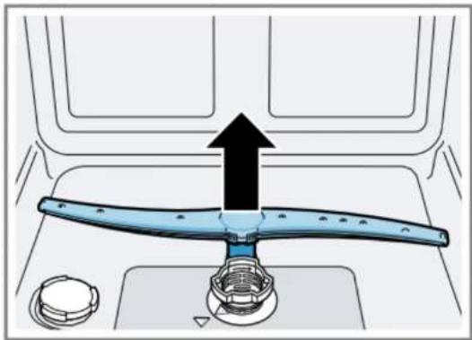
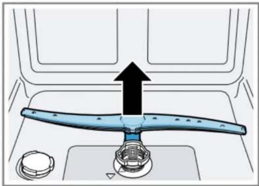
Unscrew the upper spray arm (only 60 cm BI models) (1). Pull the arm downwards (2).

Diagram showing a hand holding a tool interacting with a car, labeled with steps 1 and 2 indicating directional movement.

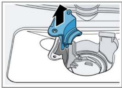
Push the lower spray arm upwards.

Diagram of a car interior showing a blue plastic lever with a black upward arrow indicating motion or force, no text or symbols present.

4.1.2 Install spray arm

Insert the lower spray arm. It will click when it is in position. Insert the upper spray arm and screw it in tightly.

4.2 Replace the filters

4.2.1 Remove the filters

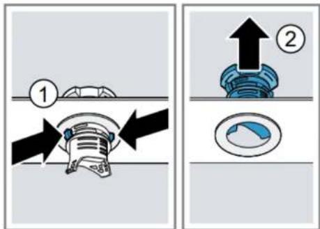
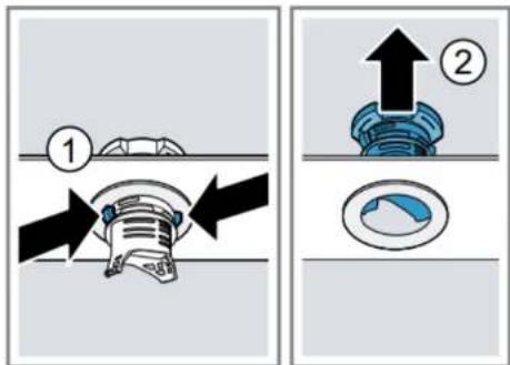
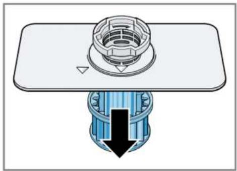
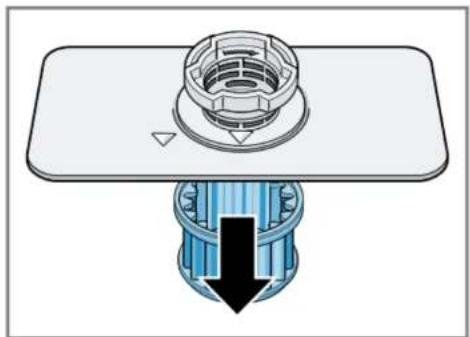
Turn the coarse filter (1) anticlockwise and remove the filter system (2).

Diagram showing a mechanical assembly with labeled parts and directional arrows indicating motion or assembly.

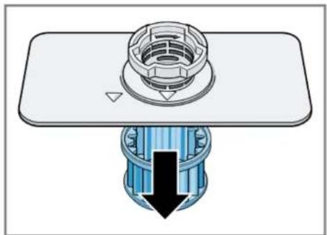
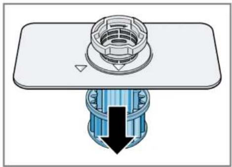
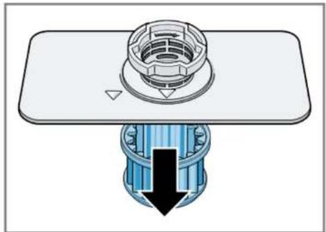
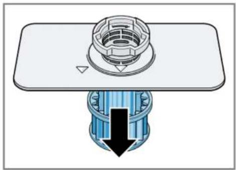
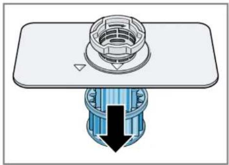
Pull down the microfilter.

Mechanical assembly diagram showing a bolted component inserted into a housing with a downward arrow indicating force (no text or symbols present).

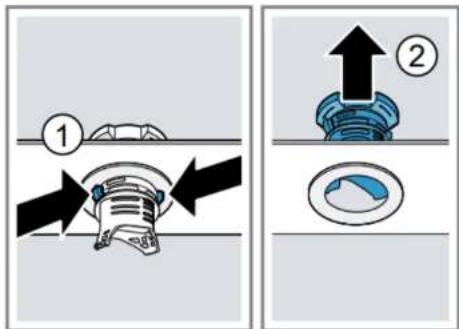
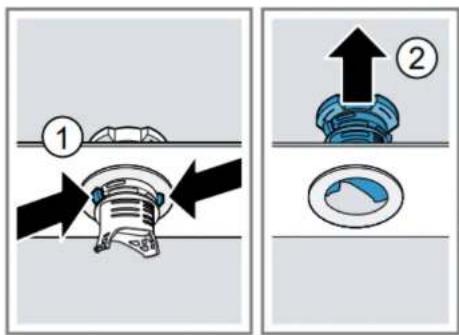
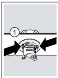
Press the catch tappets (1) and pull up the coarse filter (2).

Technical diagram showing mechanical assembly steps with numbered instructions and directional arrows.

4.2.2 Install the filters

  1. Reinstall the filtration system.

Make sure that the coarse filter's latches snap into position.

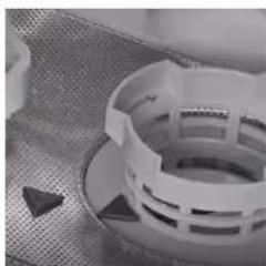
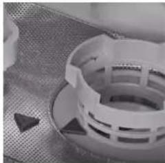
  1. Insert the filtration system into the appliance and turn the coarse filter clockwise.

Make sure that the arrow markings match up.

Close-up of a white plastic bag with a mesh grille and a small triangular object on the side (no visible text or symbols).

4.3 Replace the drain pump cover

Prerequisites:

Disconnect the appliance from the power supply.

Remove the upper and lower baskets.

Remove the filters.

Drain any water that is present. Use a sponge if necessary.

4.3.1 Remove the drain pump cover

SIEMENS SC05IB00TE - Remove the drain pump cover - 1

SIEMENS SC05IB00TE - Remove the drain pump cover - 2

BE CAREFUL

Risk of injury

▶ Wear protective gloves. Carefully remove any build-up of foreign matter.

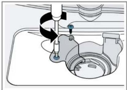
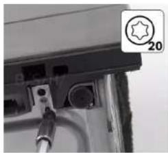
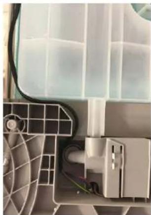
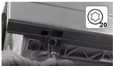
Undo fastening screws of the pump cover (T 20 torx).

Technical diagram of a mechanical assembly with no visible text or symbols.

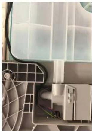
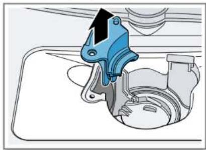
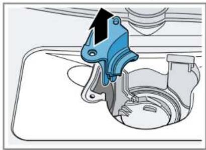
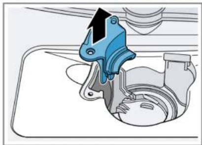
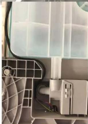
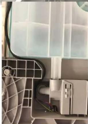
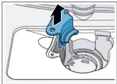
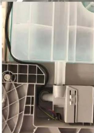
Pull the pump cover upwards.

Diagram of a mechanical assembly with a blue clamp and black arrow indicating force or direction (no text or symbols).

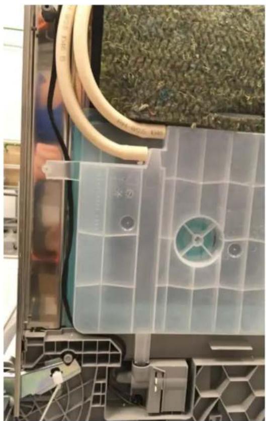
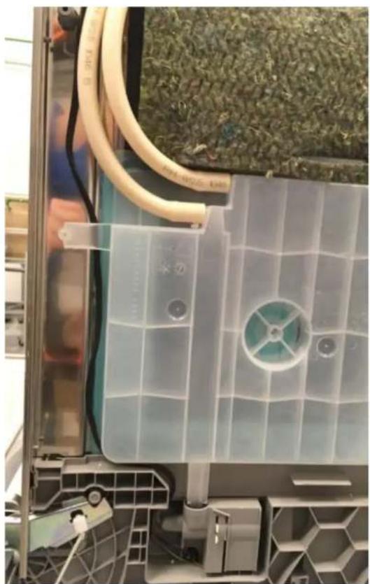
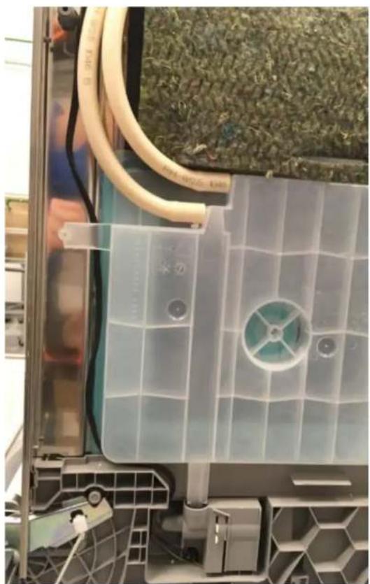
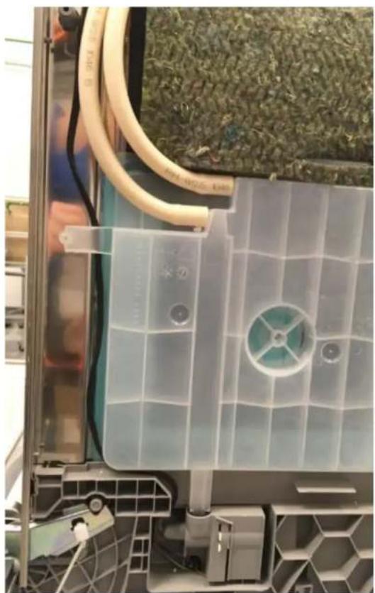
Remove any food residue and foreign matter inside the appliance.

4.3.2 Install the drain pump cover

Fit the pump cover.

Press it down and screw it in.

Install the filter system.

Insert the upper and lower baskets.

4.4 Replace plug

SIEMENS SC05IB00TE - Replace plug - 1

WARNING

Overheating of main connection!

Risk of fire in the appliance

When changing the appliance's input cable for use with sockets in the country, you should also check the country's voltage and frequency. ▶ Firmly insert it until you hear a click.

Two strong pins on either side prevent the plug from inadvertently coming loose or detaching from the appliance.

4.4.1 Assembly

Click 2

4.4.2 Disassembly

The plug is removed from the socket in the appliance by gently moving it sideways and pulling at the same time.

4.5 Basket systems

The 60 cm models have 2 baskets.

The 45 cm models only have one basket.

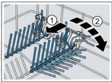
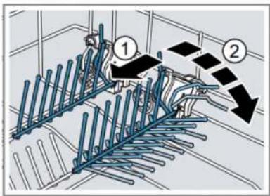
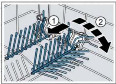
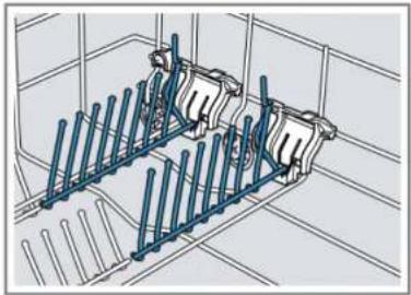
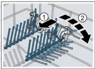
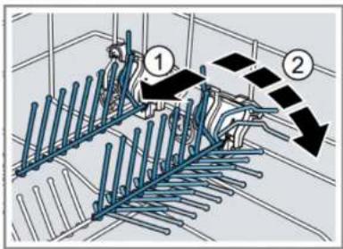
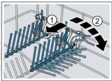
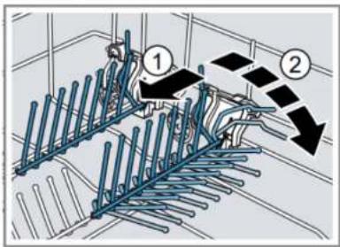
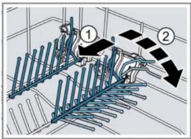
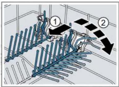
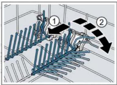
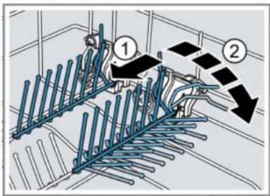
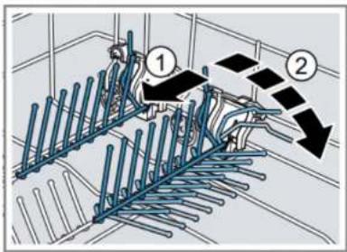
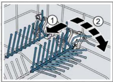
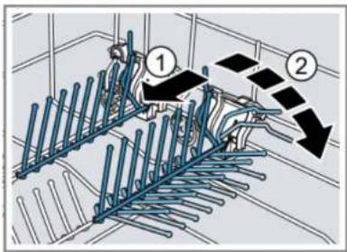
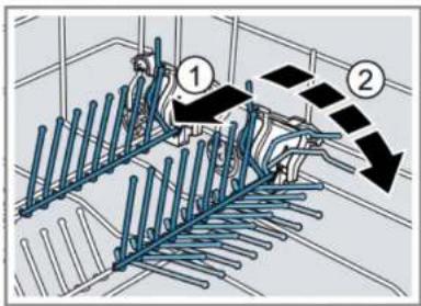
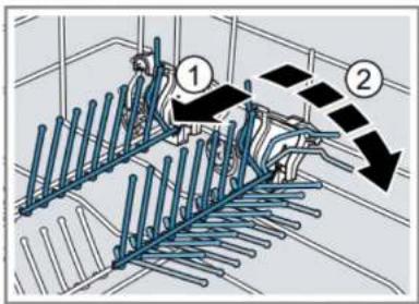
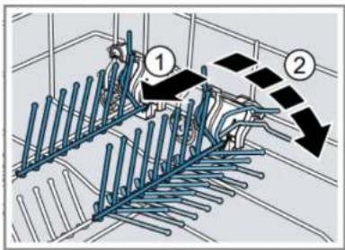
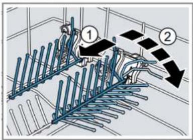
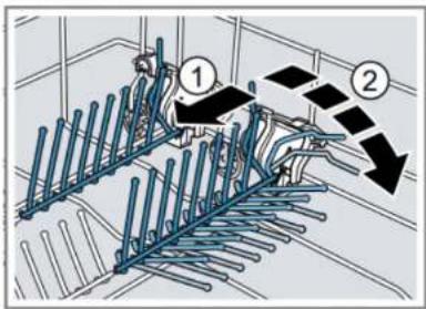
4.5.1 Folding sticks

They fit into a slit in the plastic support on the side.

Press the lever forwards when the sticks are not needed.

Technical line drawing of a mechanical assembly with vertical rods and cylindrical components (no text or symbols).

Technical diagram showing a mechanical assembly with labeled components and directional arrows indicating motion or flow.

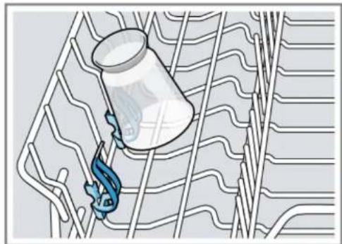
4.5.2 Additional support for small parts

Use this support for small parts that weigh little.

Illustration of a fishing rod hooking a fishing container over a wavy riverbed (no text or symbols).

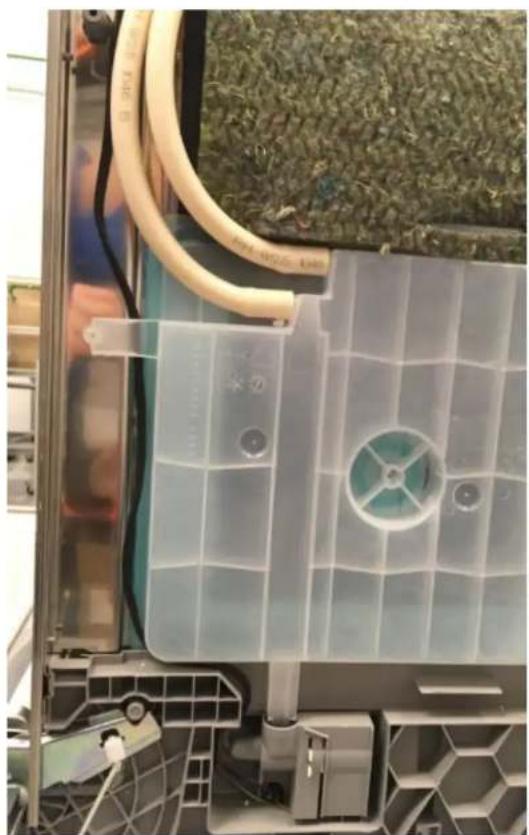
Appliance is disconnected from the mains.

Appliance is disconnected from water supply.

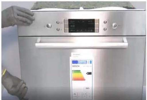
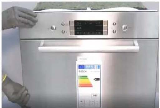
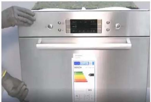
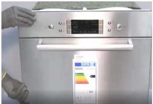
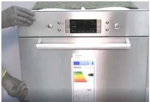
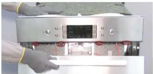
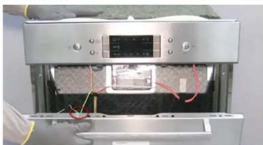
4.6.1 Remove the outer door

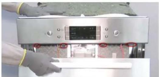
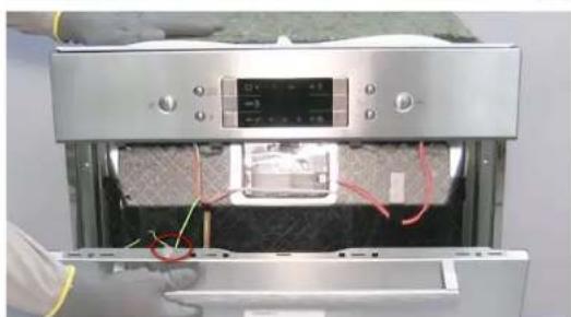
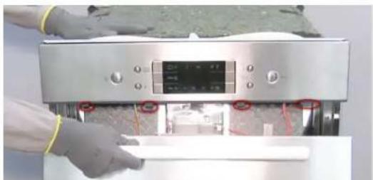
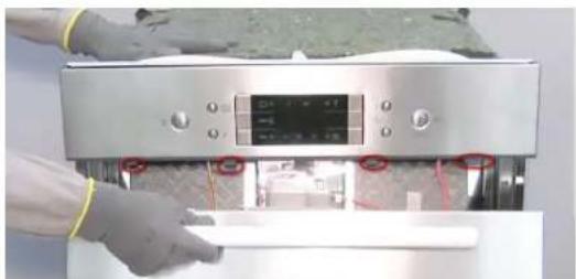
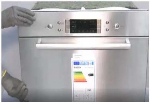
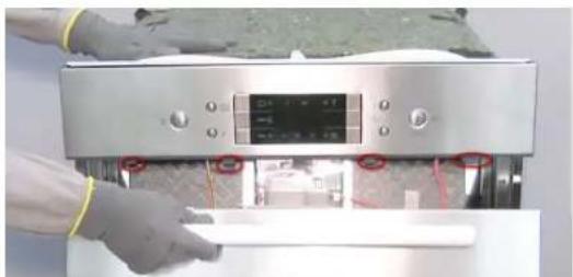
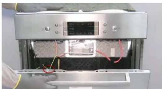
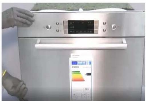
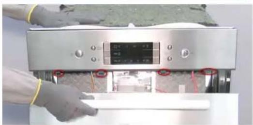
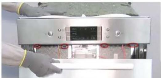
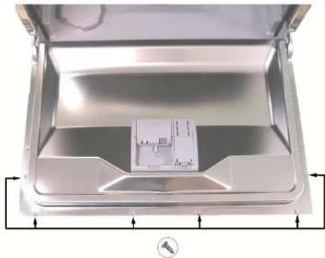
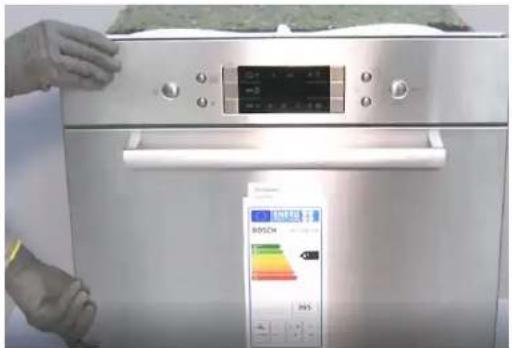
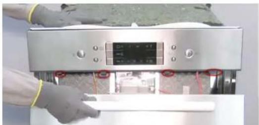
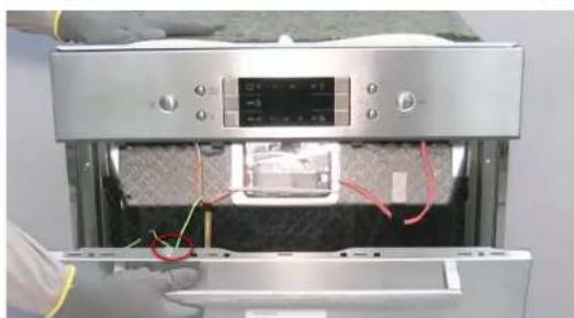
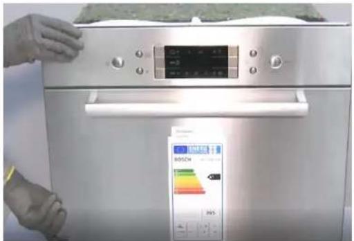
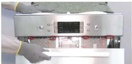
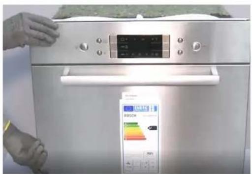
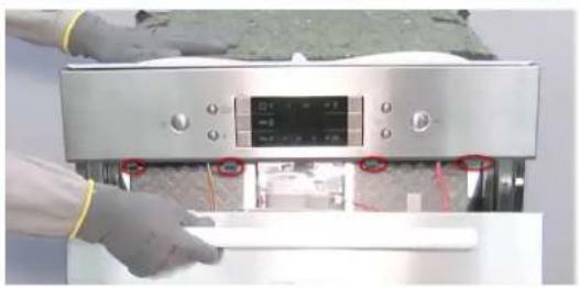
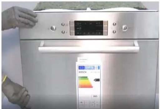
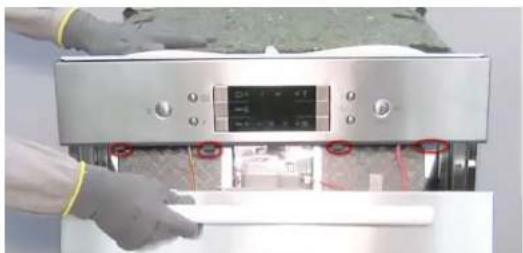
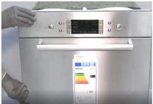
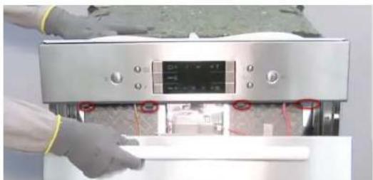
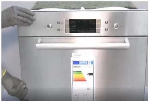
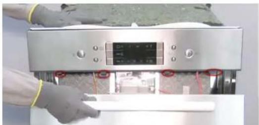
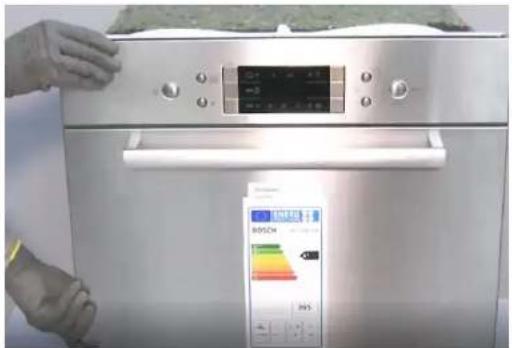
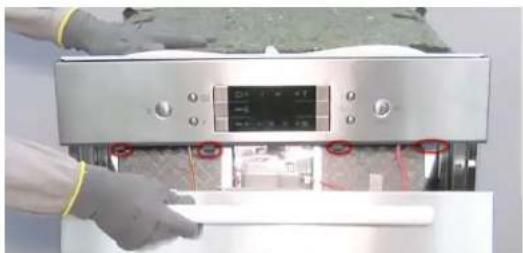
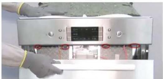
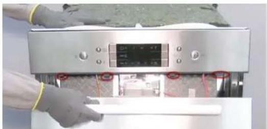
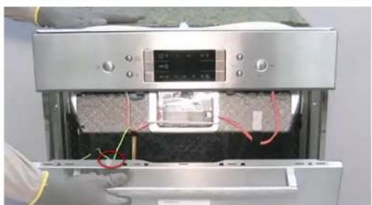
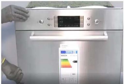
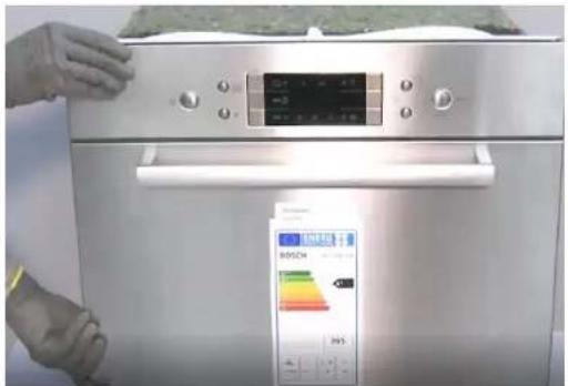
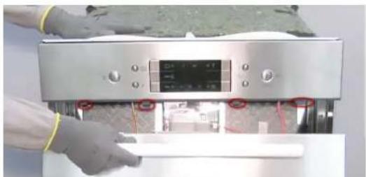
Remove the screws described below with a Torx 20 screwdriver.

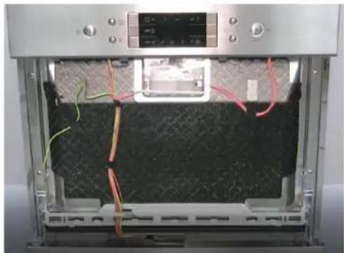
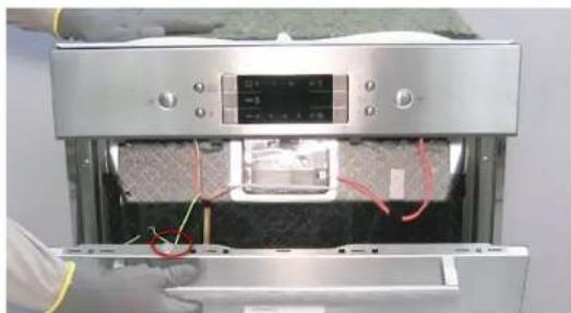
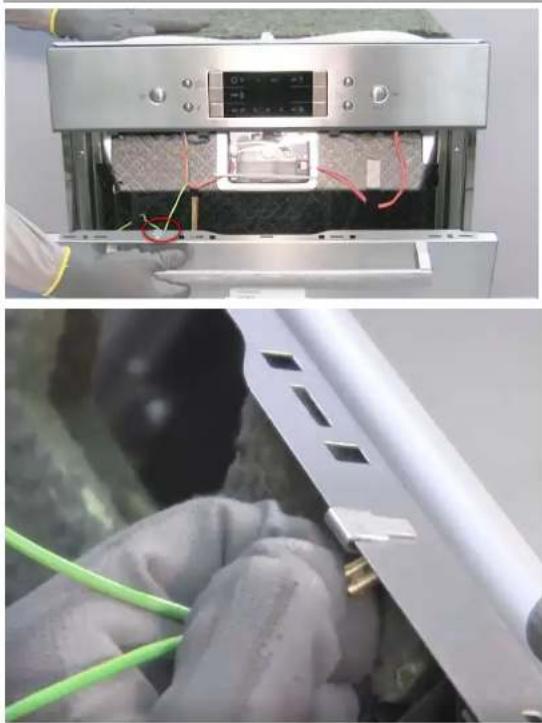
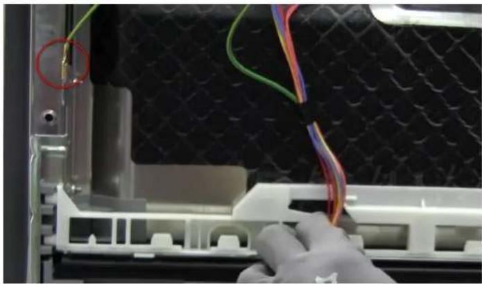
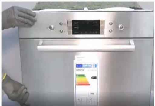
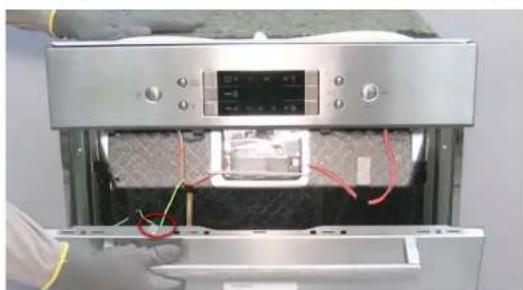
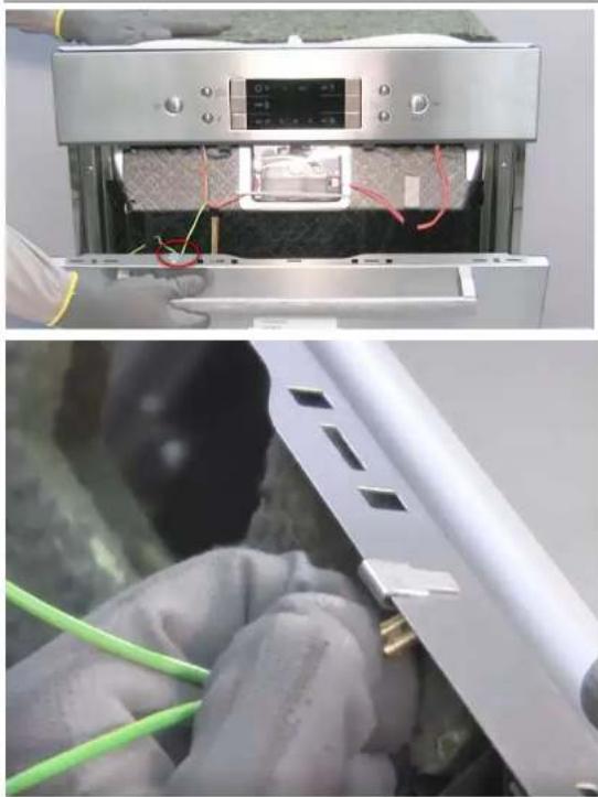
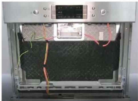
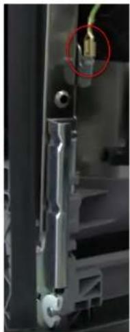
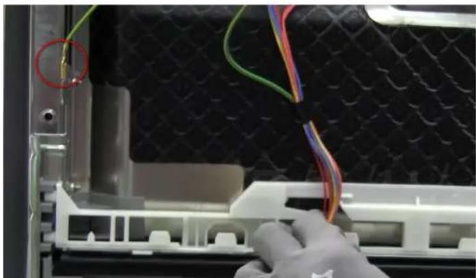
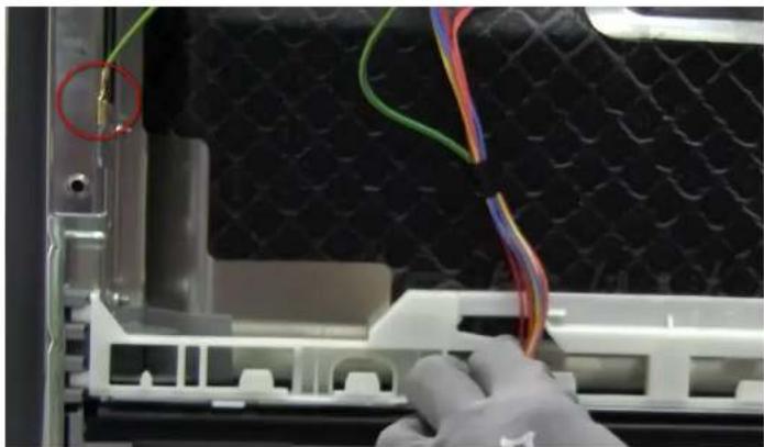
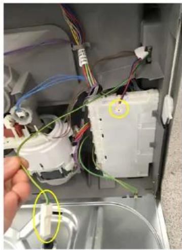
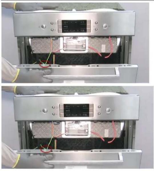
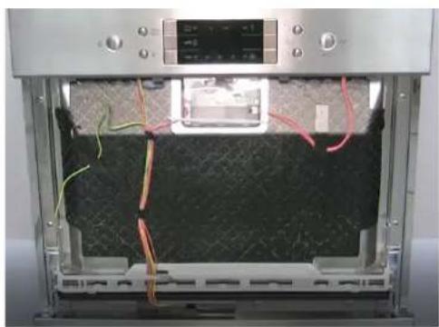
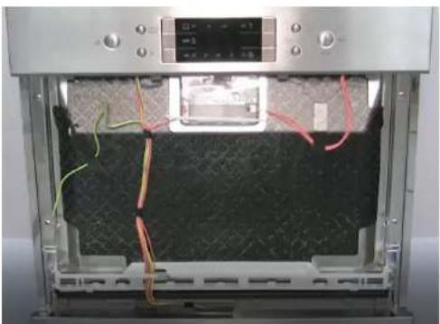
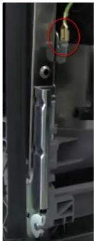
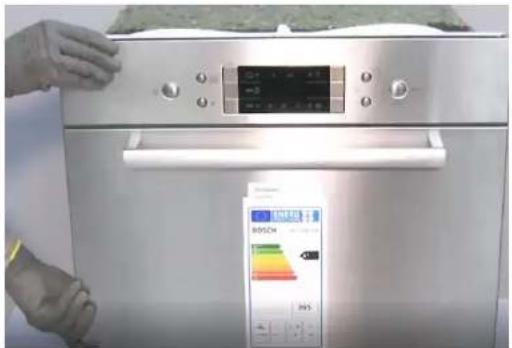
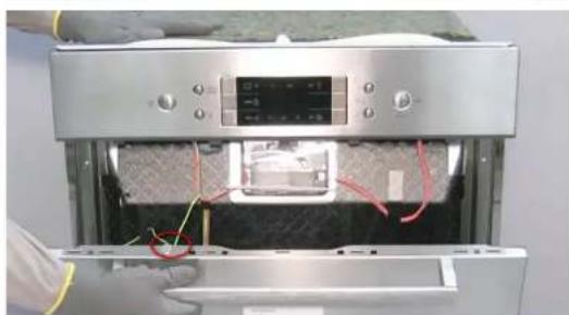
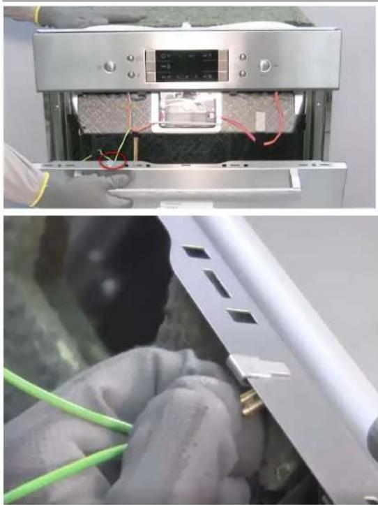
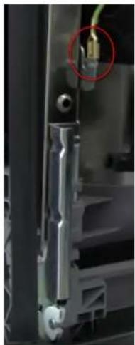
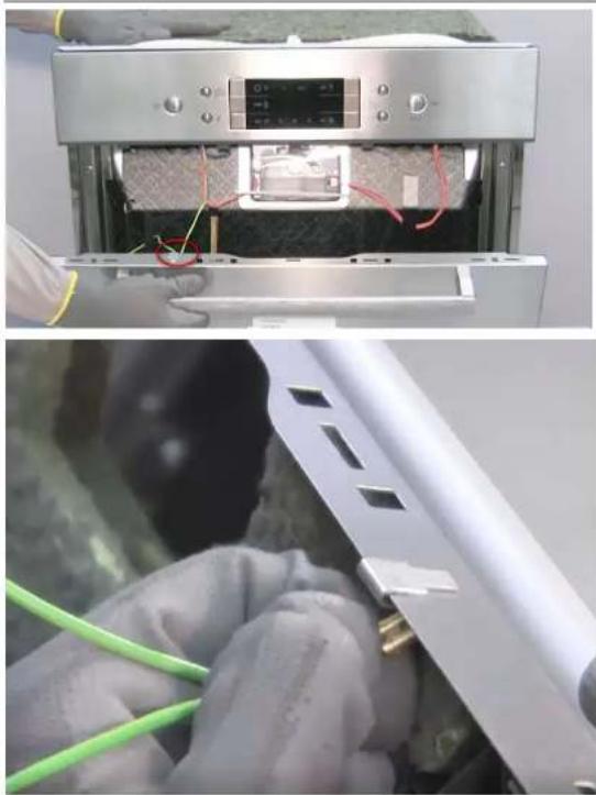
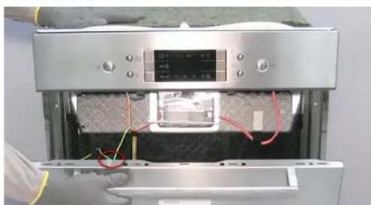
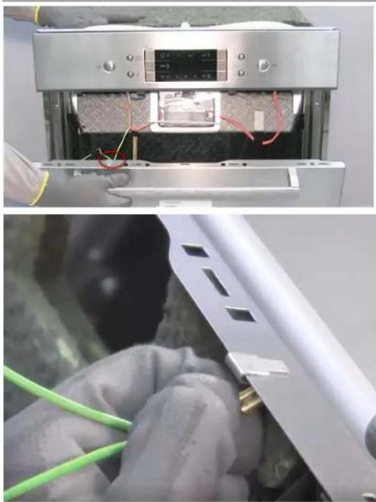
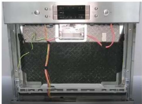
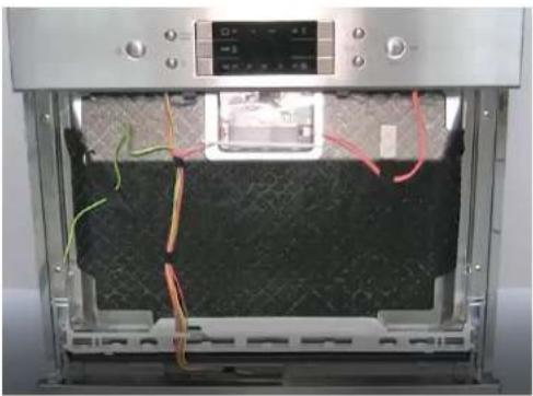
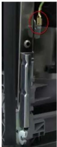
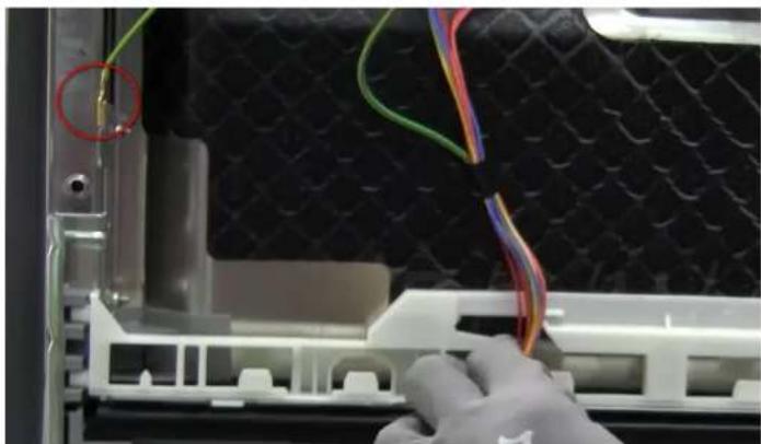
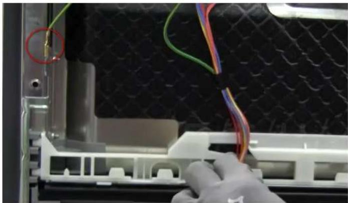
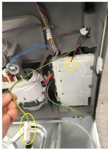
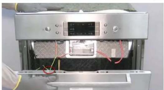
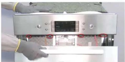
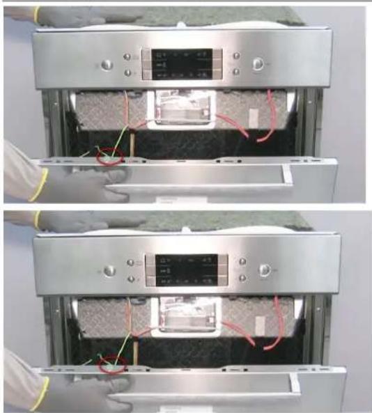
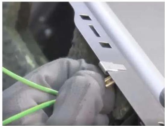
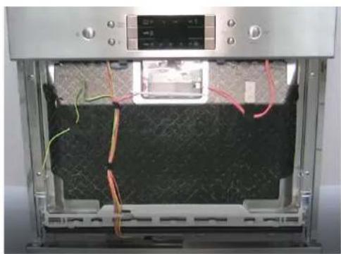
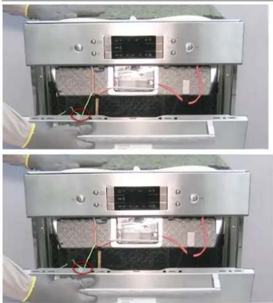
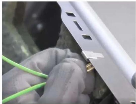
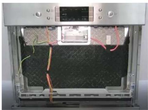
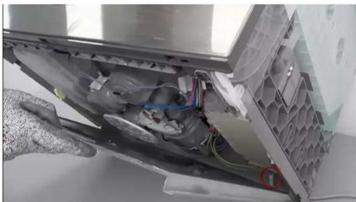
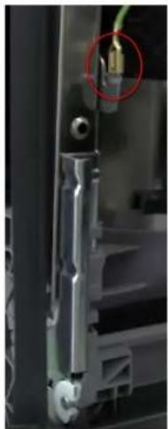
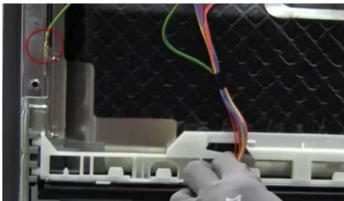
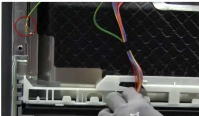
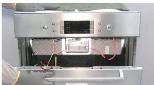
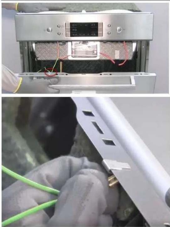
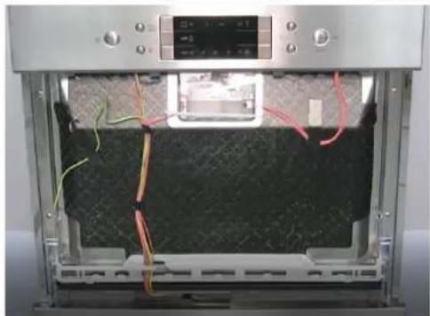
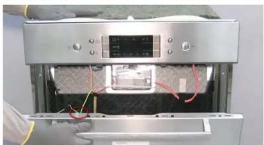
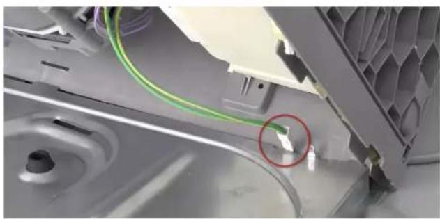
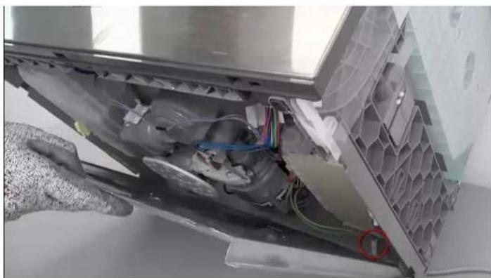
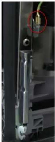
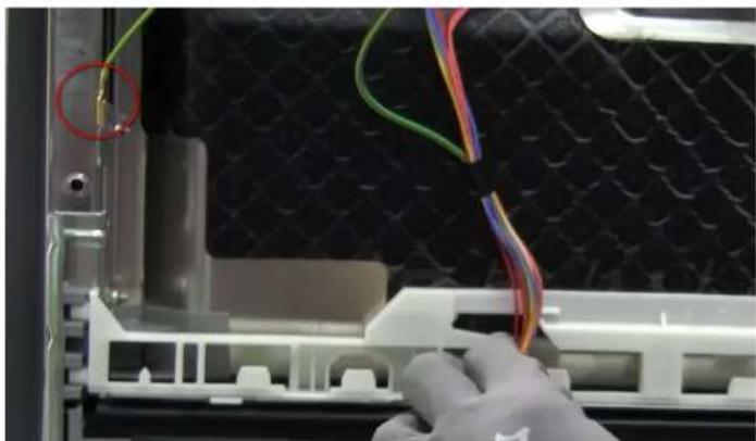
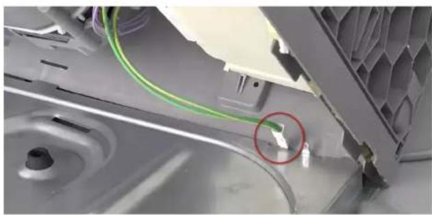
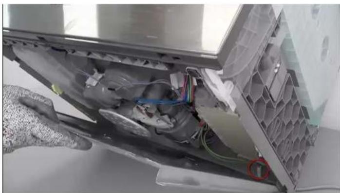
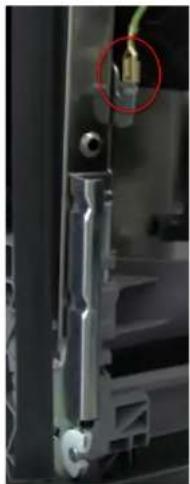
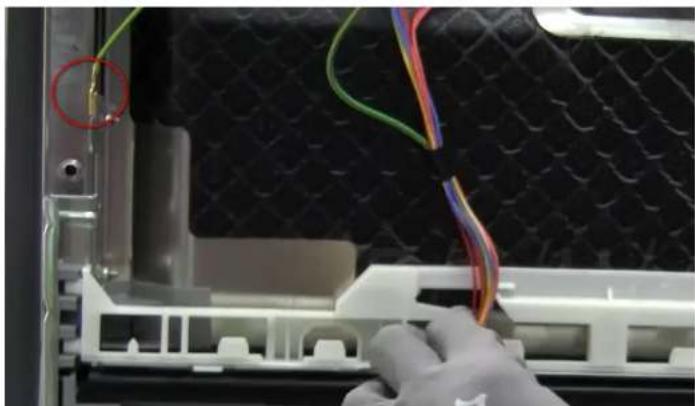
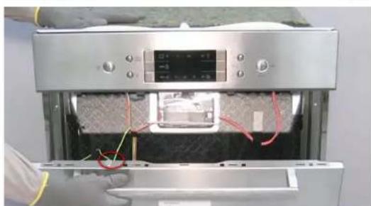
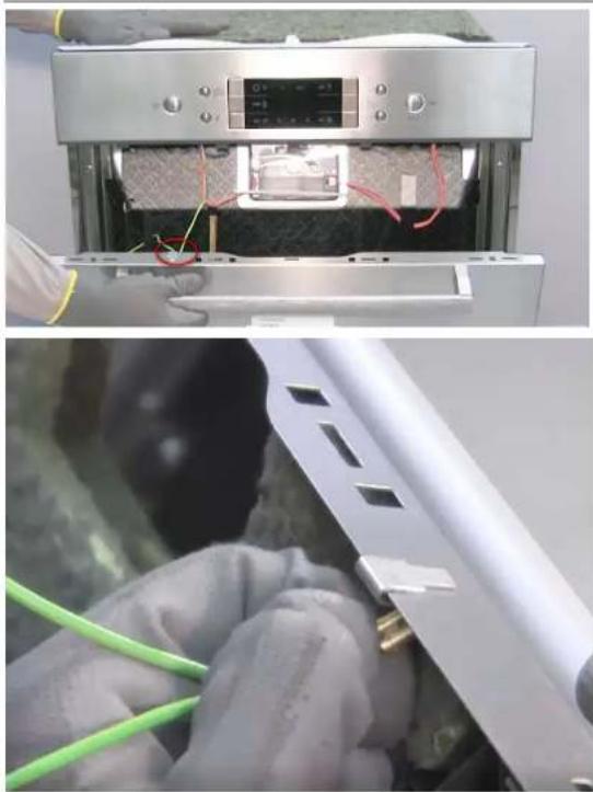
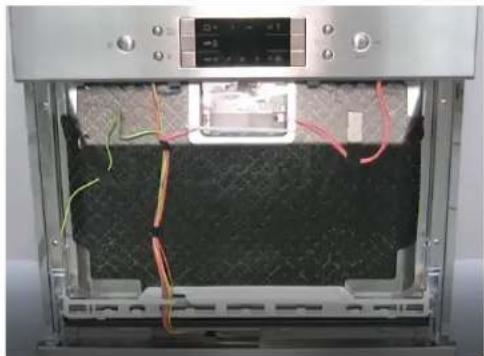
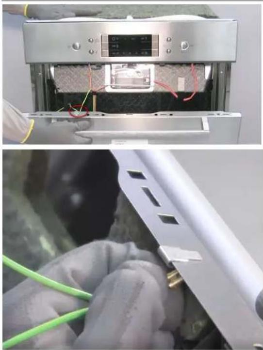
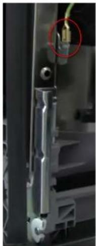
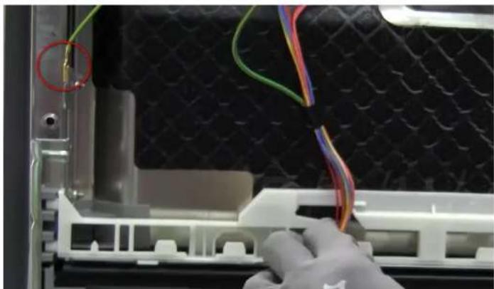
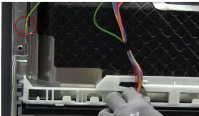
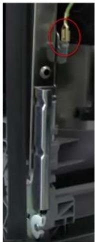
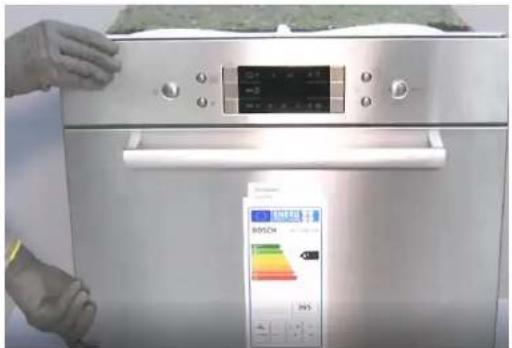
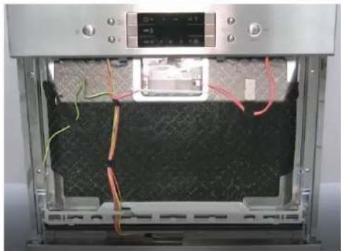
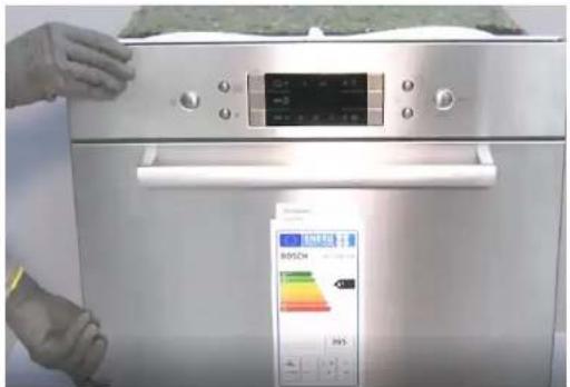
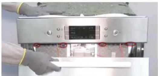
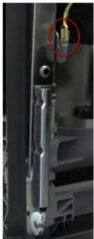
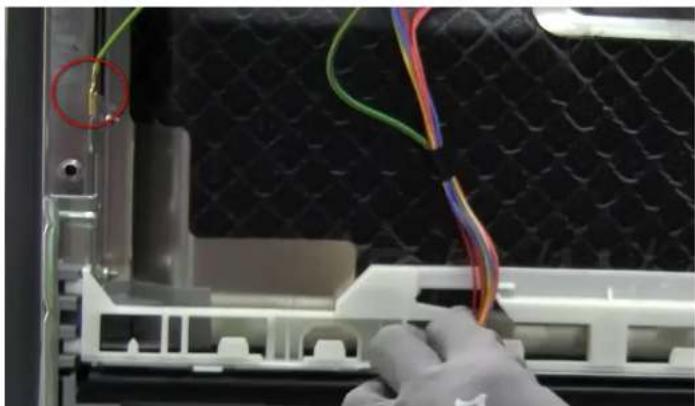
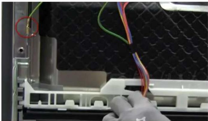
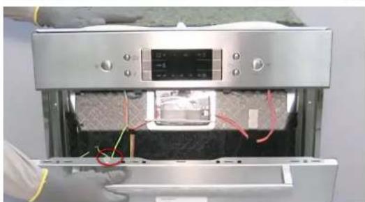
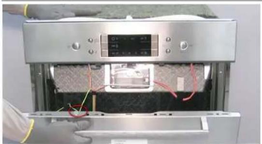
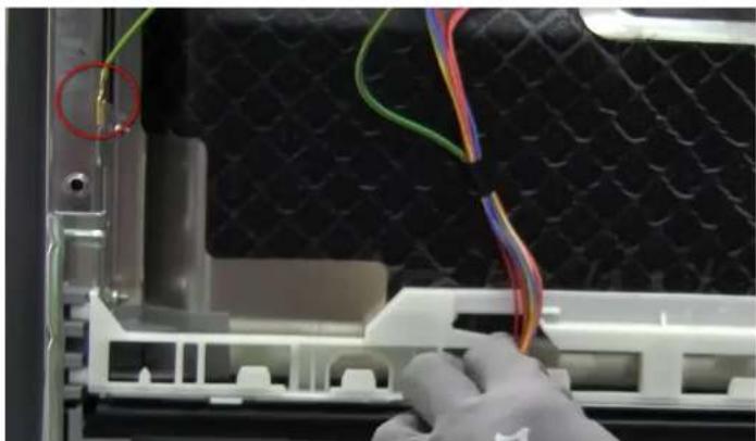
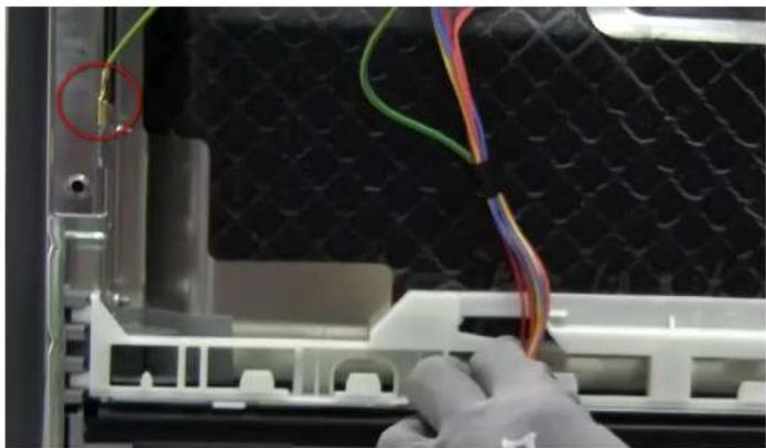
1. Open the door. 2. Remove 4 screws. 3. Close the door by holding it on one side. 4. Release the door by pulling down on its latches. 5. Disconnect the earth wire from the door.

Metallic enclosure with a central plastic housing and yellow circular annotations highlighting features (no text or symbols present).

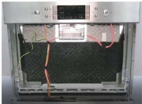
Interior view of a stainless steel kitchen appliance with a hand adjusting the door (no visible text or symbols).

Person operating a refrigerator with digital display and red annotations (no readable text or symbols).

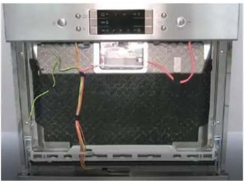
Interior view of a stainless steel appliance with red wiring and a digital display (no visible text or symbols)

Two-panel image showing a device interior with wiring and a close-up of hands installing or maintaining components (no visible text or symbols)

Interior view of a 3D printer oven with visible wiring and control panel (no text or symbols)

SIEMENS SC05IB00TE - Remove the outer door - 7

Panel screws

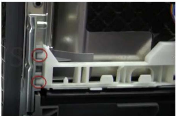
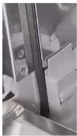
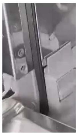
The inner door's 2 lateral screws secure the hinges to the inner door.

Close-up of a metal cutting machine with red circles highlighting specific features (no text or symbols visible)

Follow the steps in reverse order.

SIEMENS SC05IB00TE - Panel screws - 2

WARNING

Cables not properly secured or incorrectly positioned!

Risk of damage to cable harness.

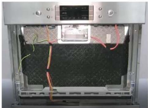
▶ Position the cables and secure in place with adhesive tape.

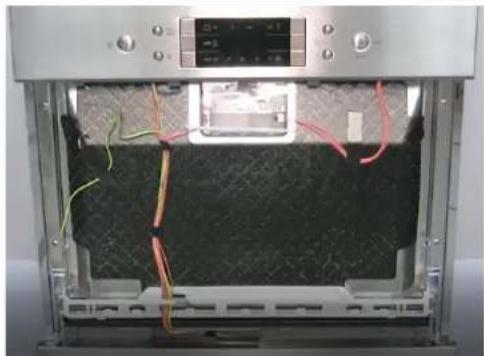
Close-up of gloved hands holding a flexible cable with multicolored wires, partially enclosed in a white plastic enclosure (no visible text or symbols)

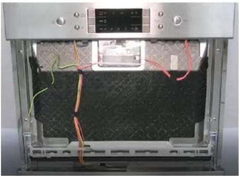
Interior view of an open industrial machine with visible wiring and control panel (no text or symbols)

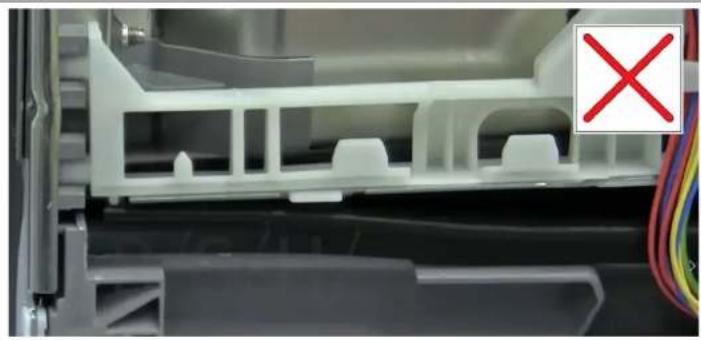
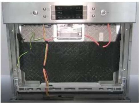
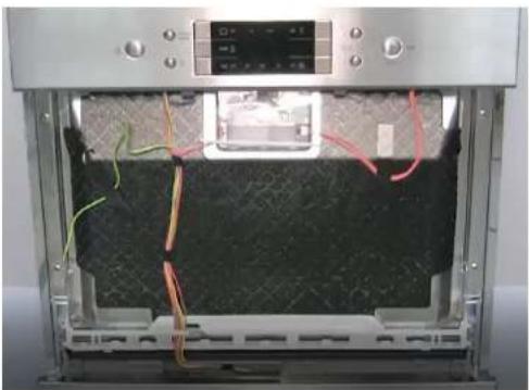
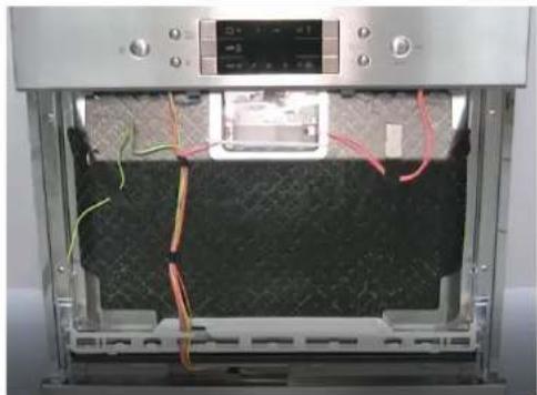
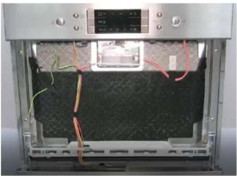
Position the cable harness correctly in the lower seal bracket.

4.7 Replace the control panel

Prerequisites:

Appliance is disconnected from the mains.

Appliance is disconnected from water supply.

The outer door has been removed.

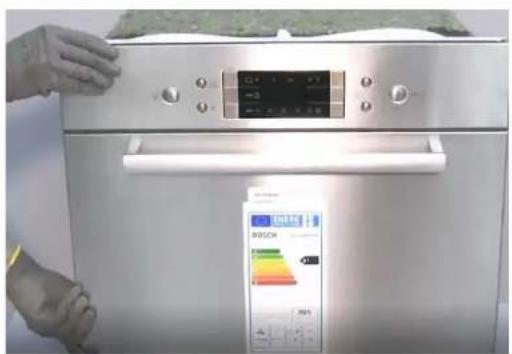
4.7.1 Remove the control panel

  1. Disconnect the electrical connections from the control panel and the 'No rinse aid' warning sensor.
  2. Open the door
  3. Hold the front panel with one hand to stop it falling off.
  4. Remove the 6 torx screws.
  5. Remove the control panel

Interior view of a stainless steel appliance with internal compartments and mounting holes (no text or symbols visible)

4.7.2 Install control panel.

Follow the steps in reverse order.

4.8 Replace the detergent dispenser cover

A small screwdriver can be used as a levering tool.

Prerequisite:

Appliance is disconnected from the mains.

Appliance is disconnected from water supply.

Door has been opened.

Detergent cover has been opened.

4.8.1 Remove the detergent cover

  • Slide the detergent cover inwards 5 mm.
  • Use a lever to remove the detergent cover from the underside of the guide rails and remove the detergent cover from the upper side of the guide rails.
  • Remove the spring.

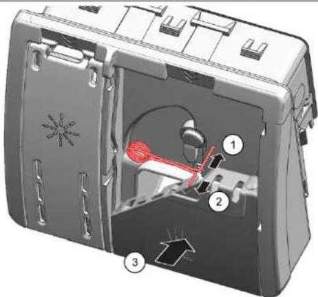
4.8.2 Insert the spring

  • Insert the long end of the spring into the mounting hole of the dispenser device (1).
  • Insert the short edge of the spring into the mounting hole of the detergent cover (2).
  • Press the cover onto the dispenser (3).

Technical diagram of a device interior with numbered components and labeled parts

4.8.3 Install the detergent cover

  • Insert the detergent cover into the guide rails on one side, to 5 mm before the fully open position. Gently applying force, press the opposite side of the guide rails.
  • Check the operation of the detergent cover.

4.9 Replace the lower door seal

Prerequisite:

√ Outer door is disassembled.

4.9.1 Disassembly

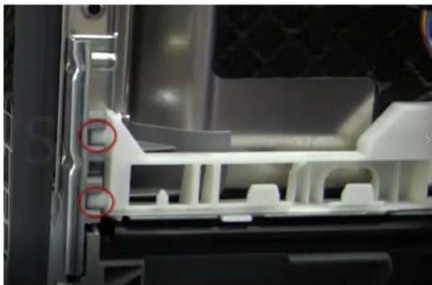
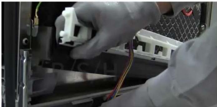
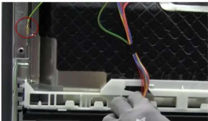
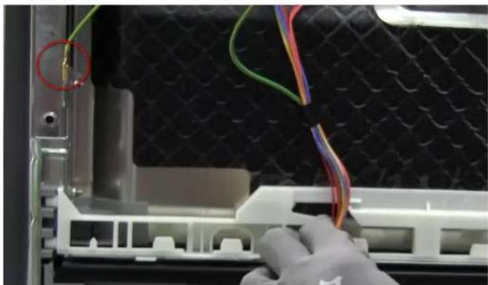
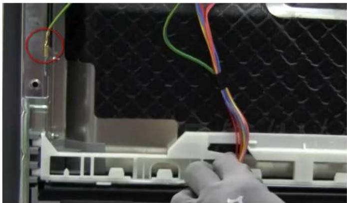
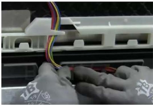
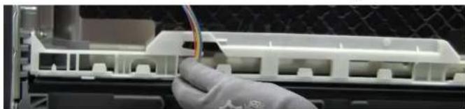
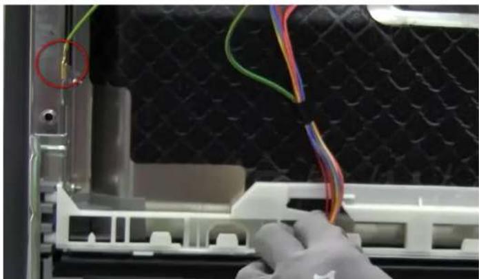
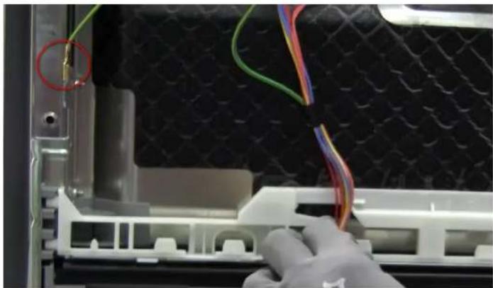
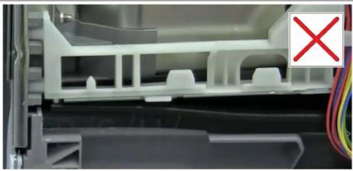
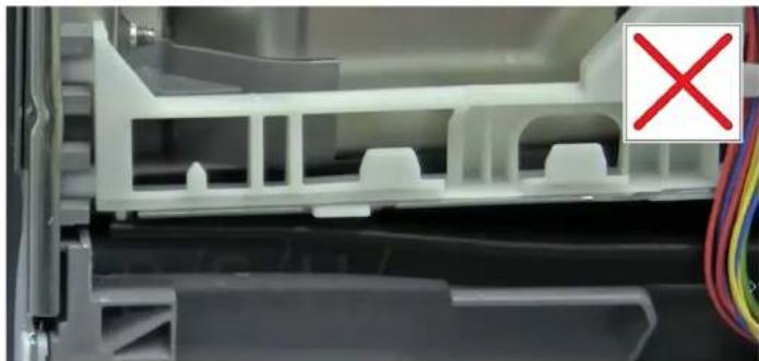
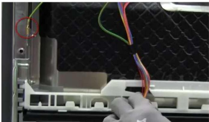
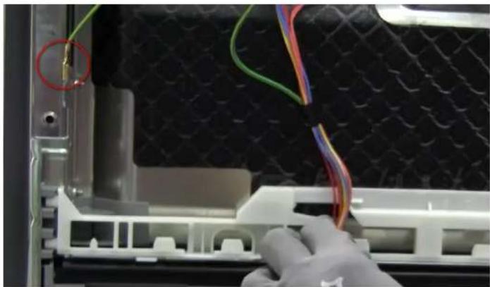
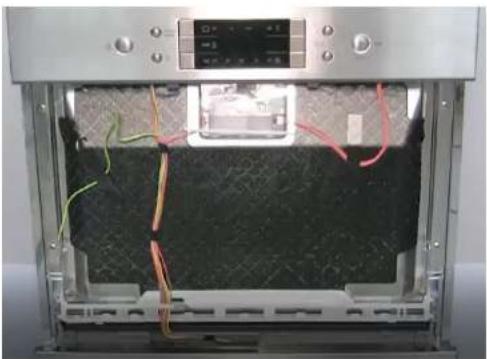
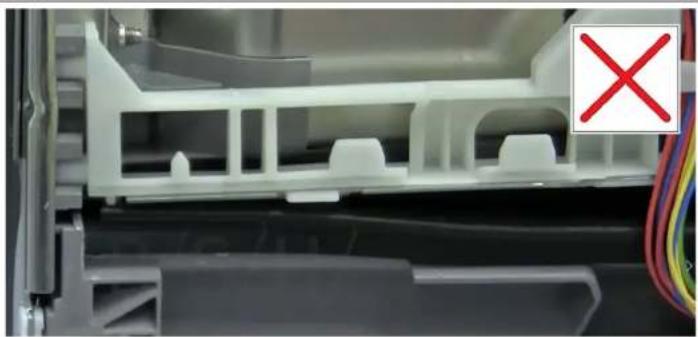
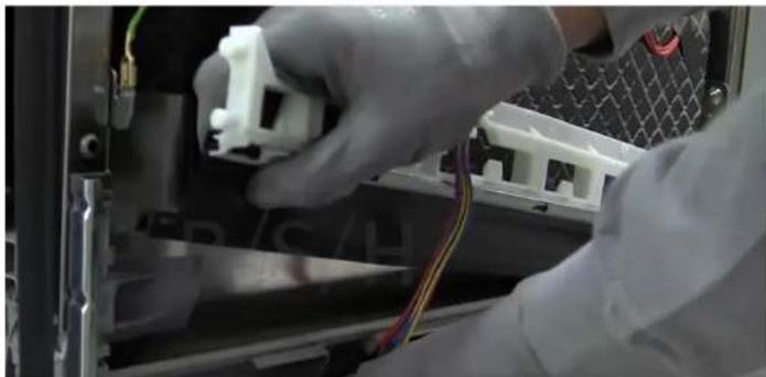
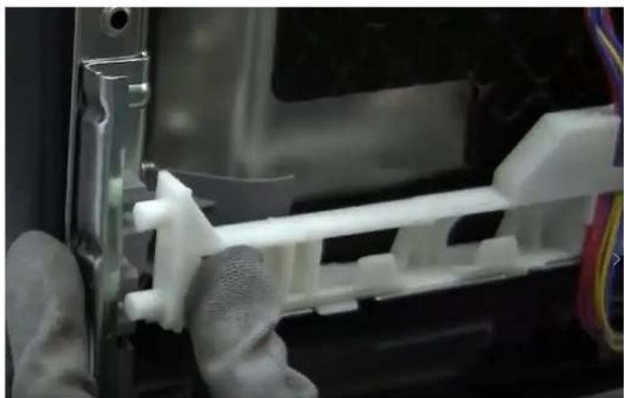
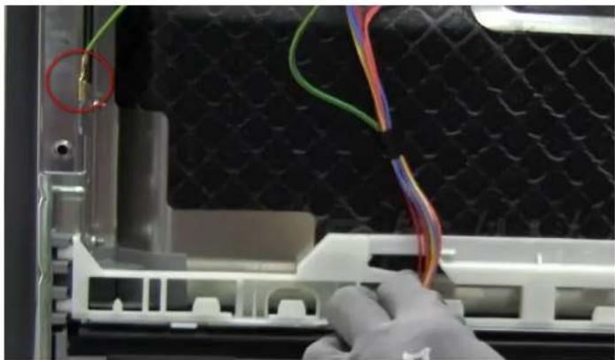
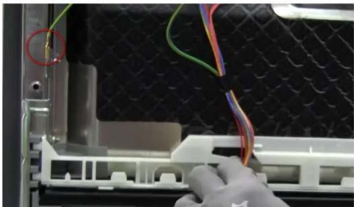
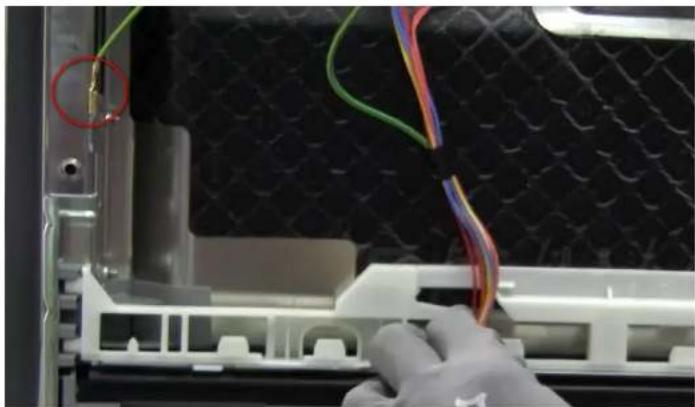
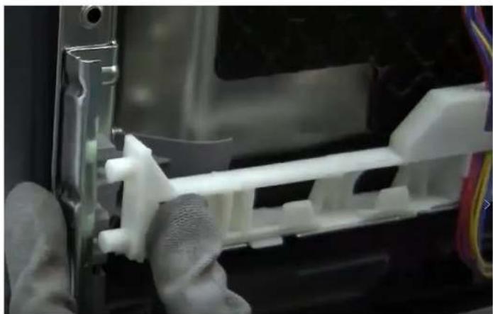
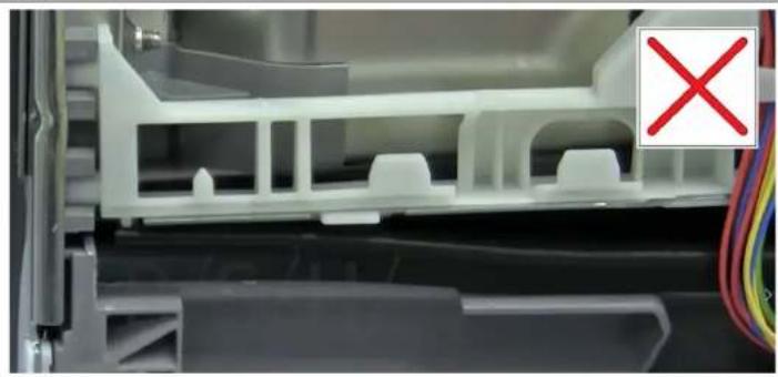
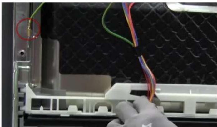
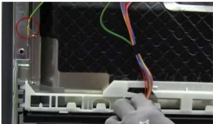
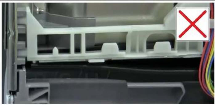
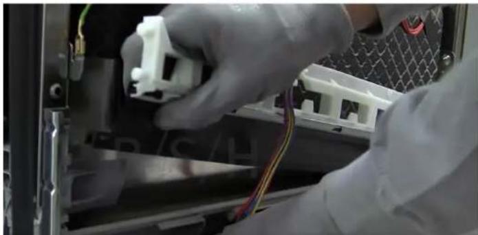
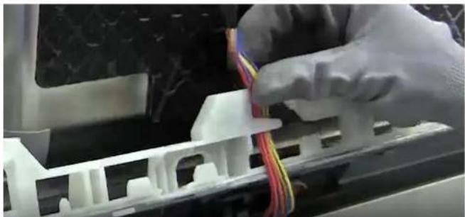
Remove the cable harness from the white bracket guide.

Close-up of a hand holding a cable inserted into a plastic electronic component (no visible text or symbols)

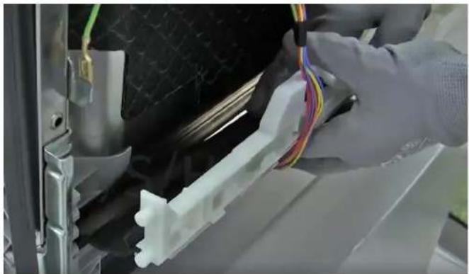
Remove it from its lower attachment position.

Close-up of a mechanical component with red circles highlighting specific parts (no visible text or symbols)

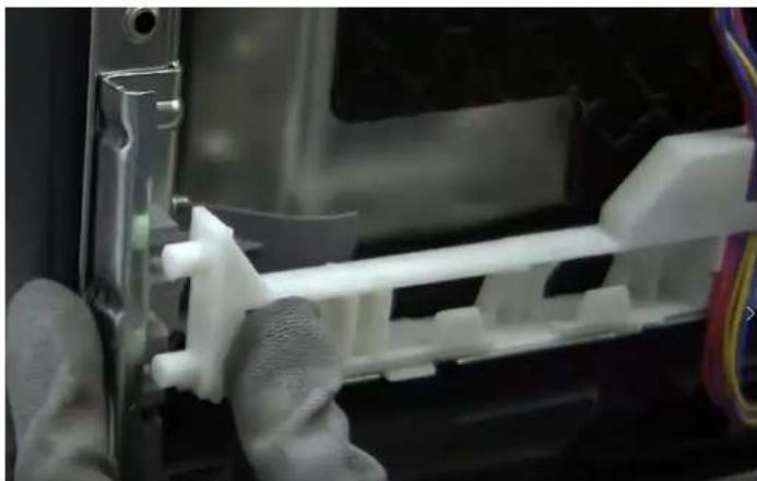
Pull it upwards to detach from the base.

Close-up of a gloved hand installing or adjusting a white plastic component on an electronic device (no visible text or symbols)

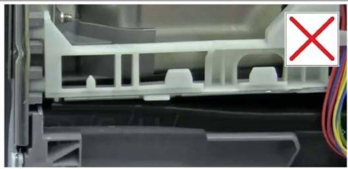
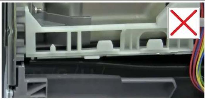
4.9.2 Assembly

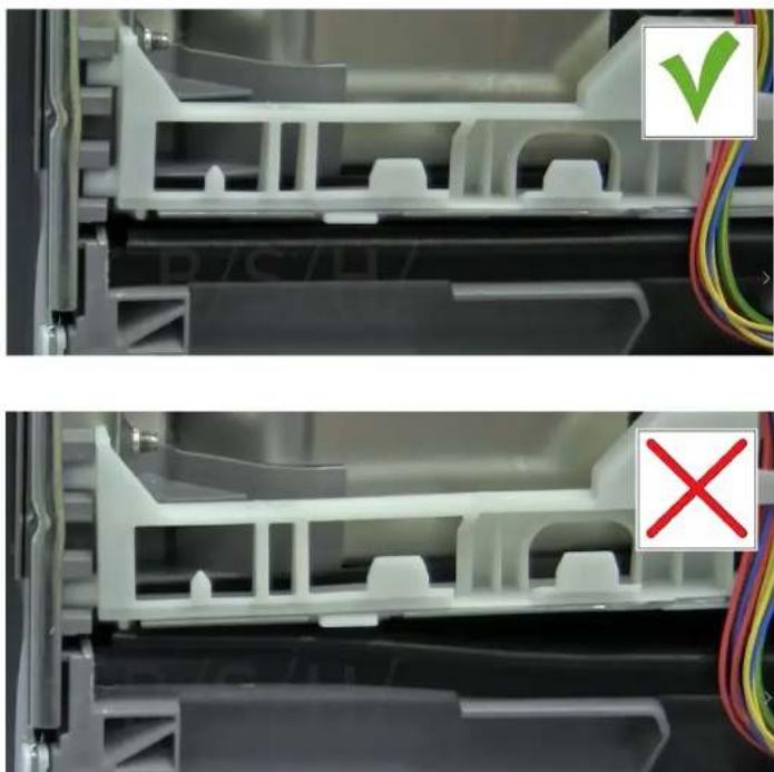
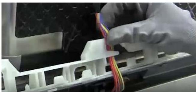
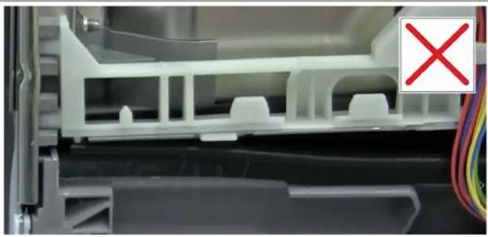
Follow the disassembly steps in reverse order to assembly. Position the seal and press on the base to fix it in place.

Close-up of hands installing a white plastic component with multicolored wires, next to a black textured object (no visible text or symbols)

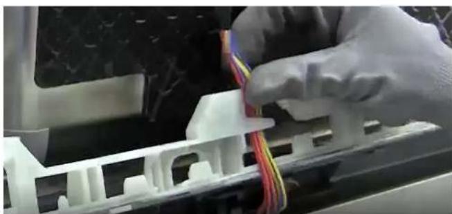
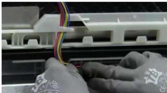
Feed the cable harness into the white support.

Close-up of hands installing or adjusting a white plastic component with red and yellow wires (no visible text or symbols)

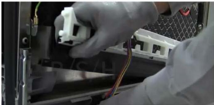
Fix the white support to the base.

Close-up of gloved hands assembling a white plastic mechanical component inside a device casing (no visible text or symbols)

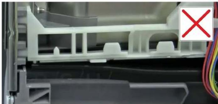
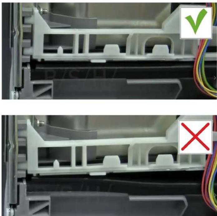
Ensure correct cable routing.

Close-up of hands operating a 3D printer with visible wiring and components (no text or symbols)

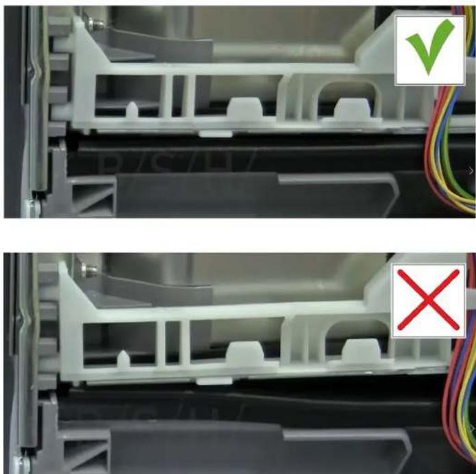
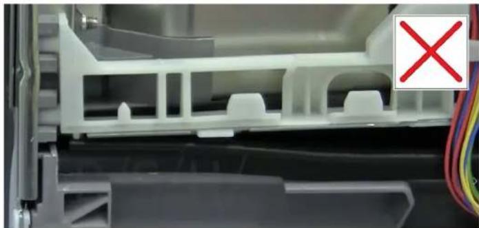
Check that the seal is flush with the lower base.

SIEMENS SC05IB00TE - Assembly - 5

4.10 Replace the door seal

Prerequisite

Appliance is disconnected from the mains.

Appliance is disconnected from water supply.

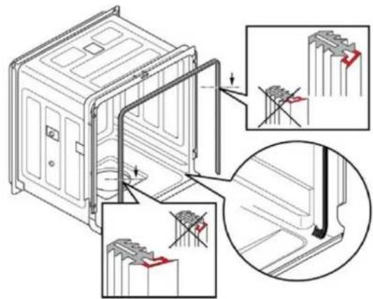
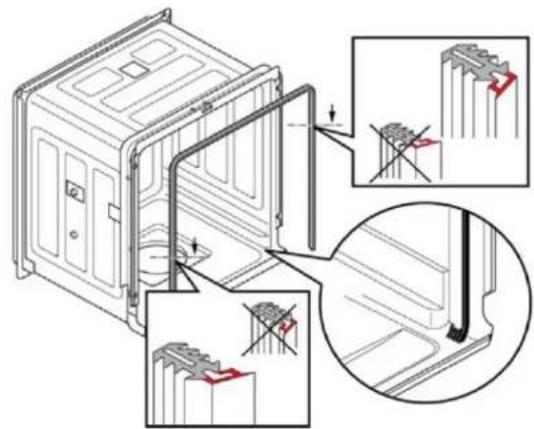
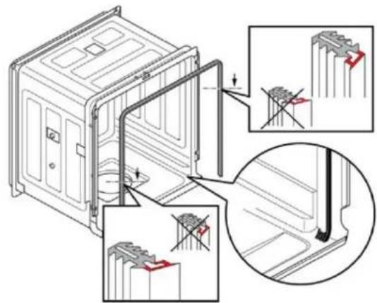
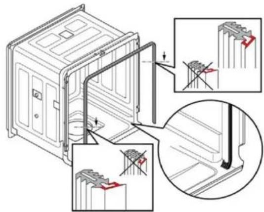
4.10.1 Remove the door seal

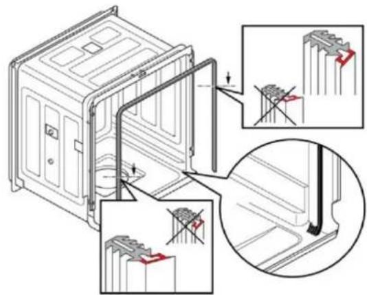
Remove the seal from the inner frame.

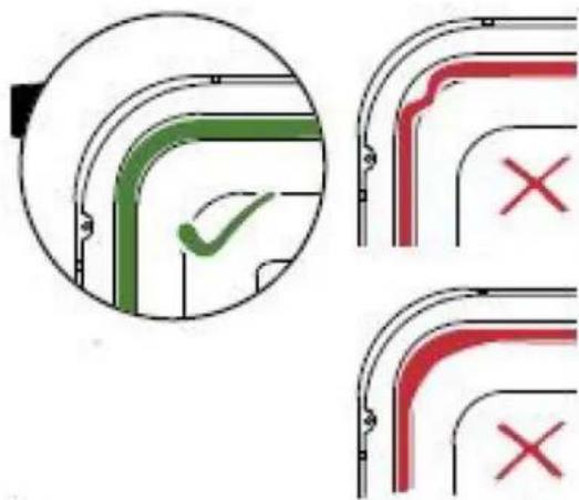
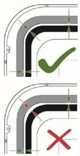
4.10.2 Install the door seal

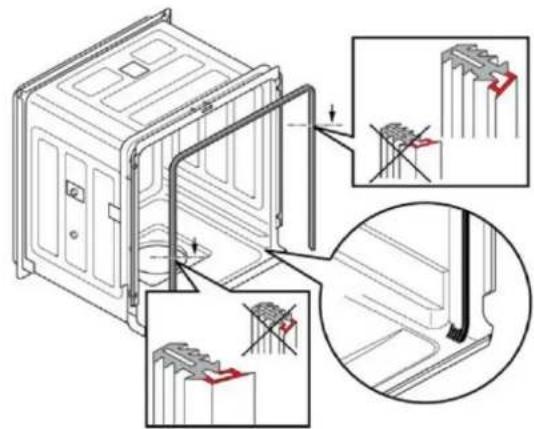
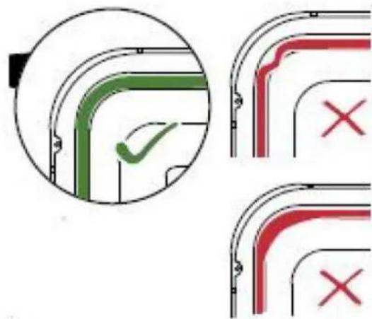
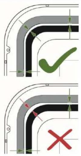
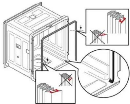
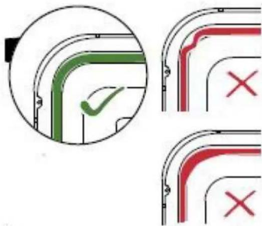
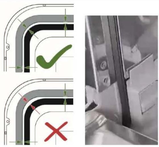
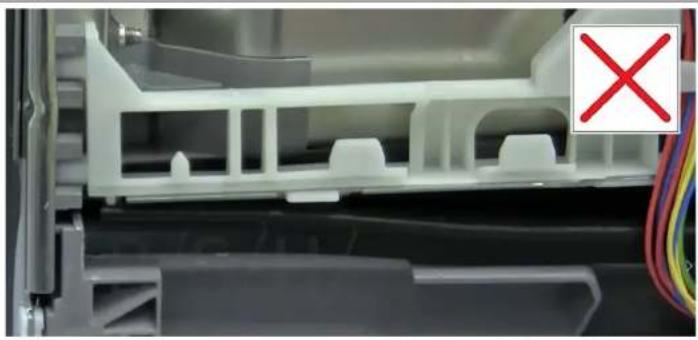
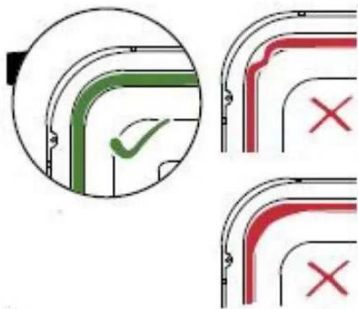
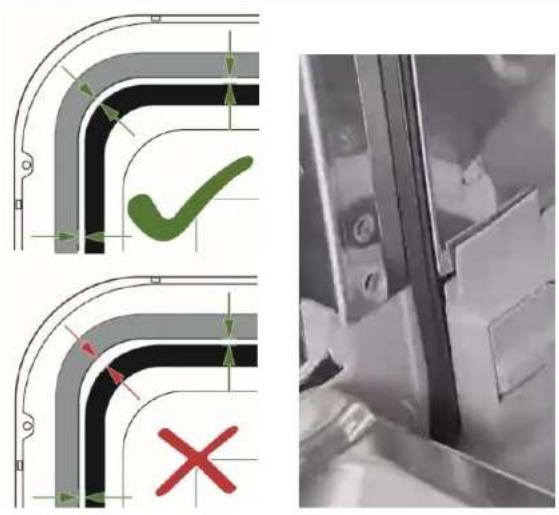
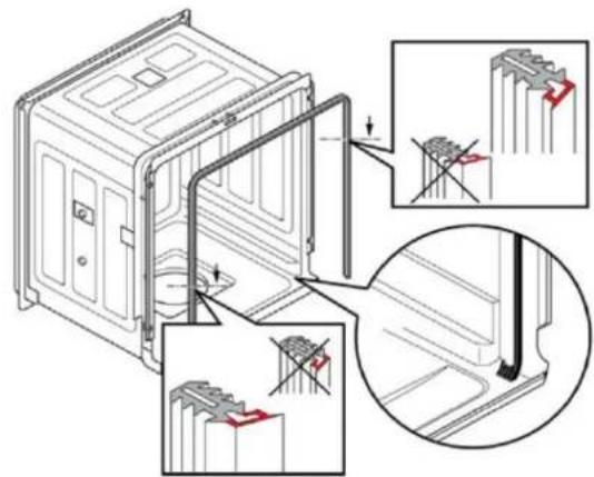
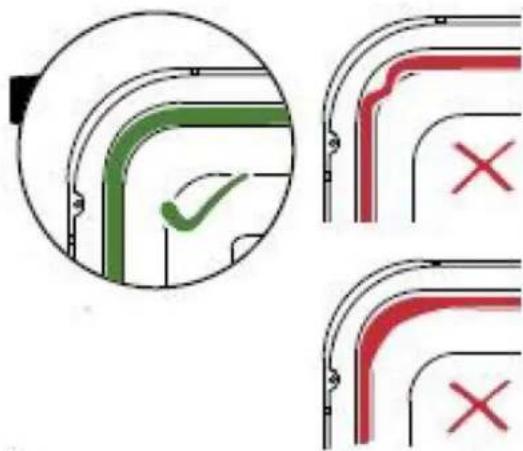
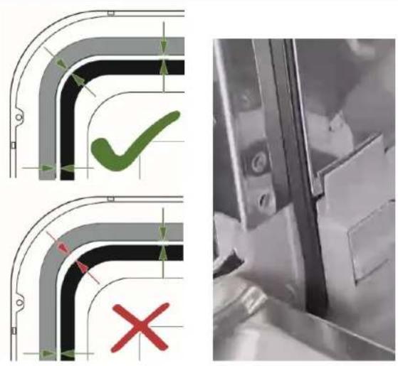
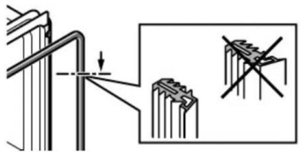
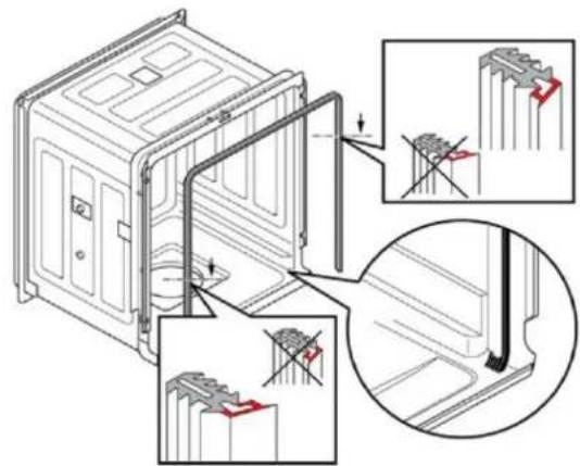
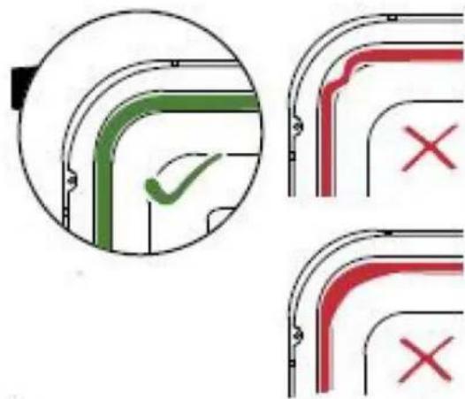
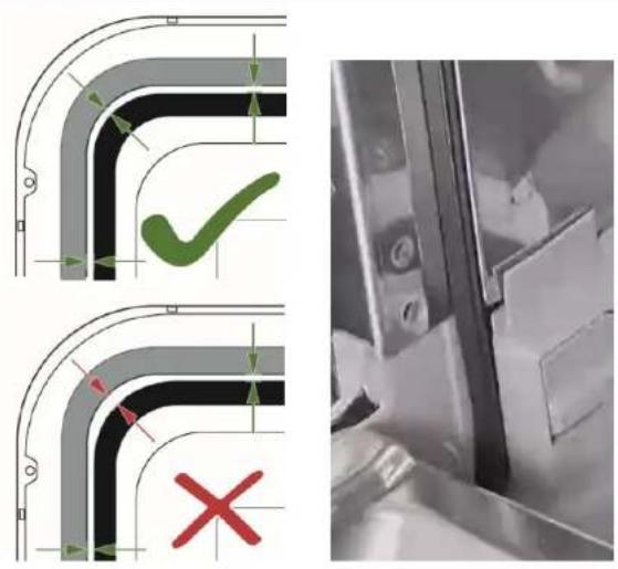
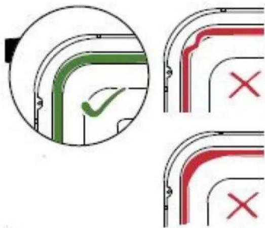
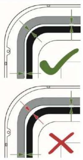
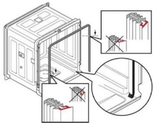
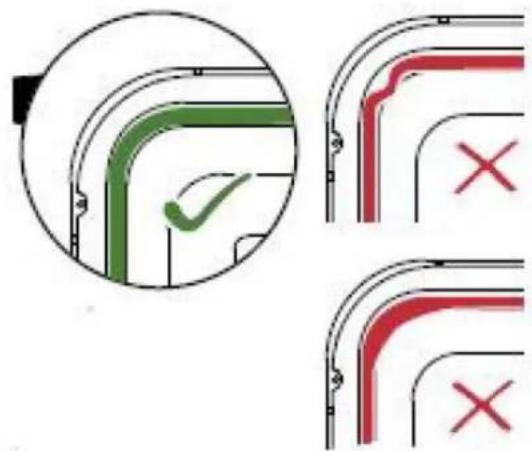
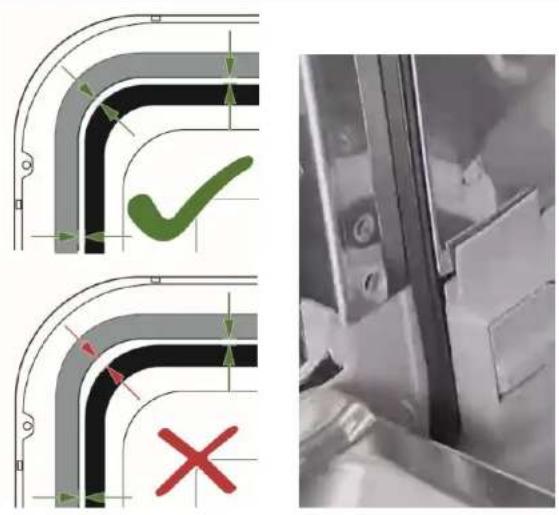
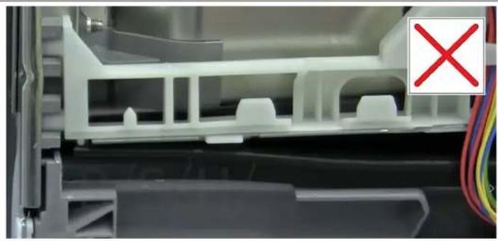
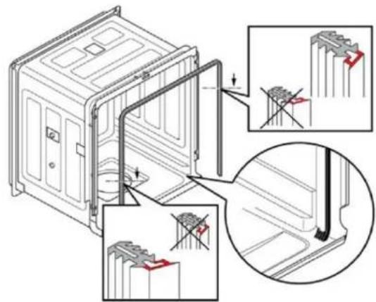
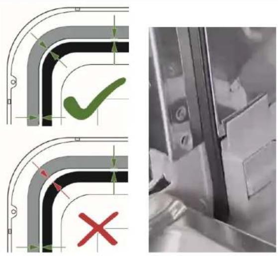
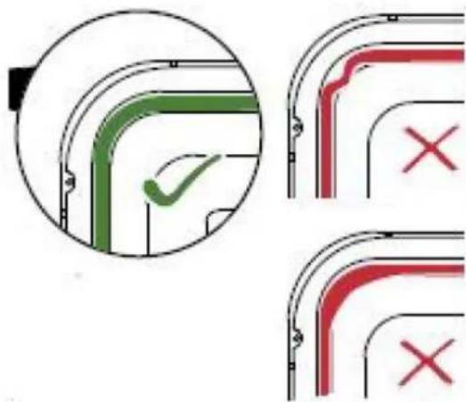
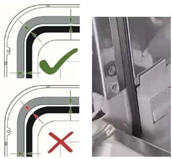
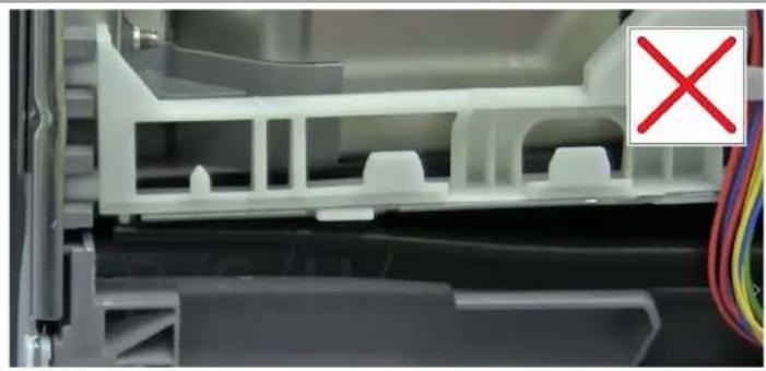
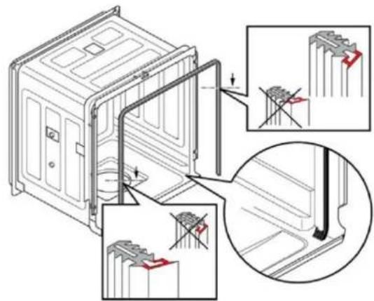
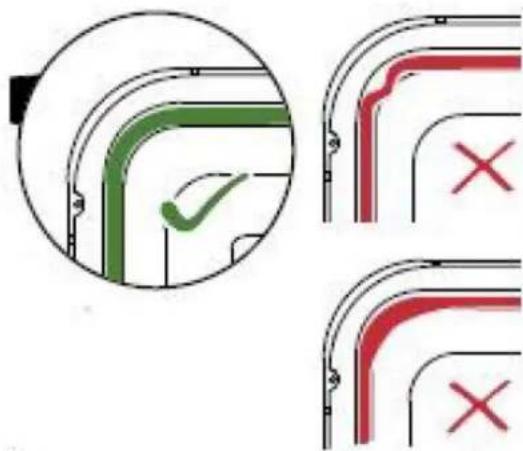
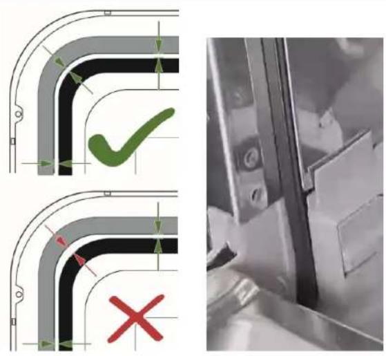
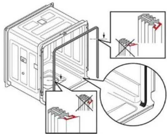
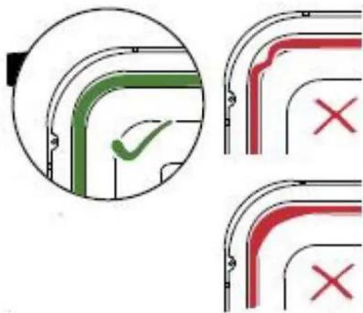
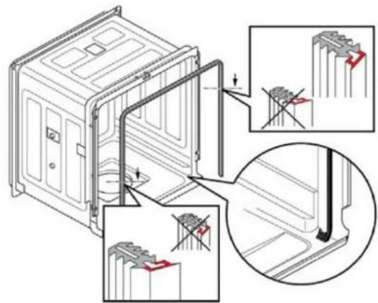
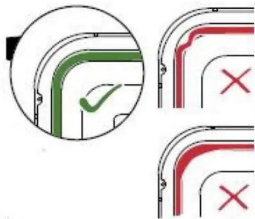
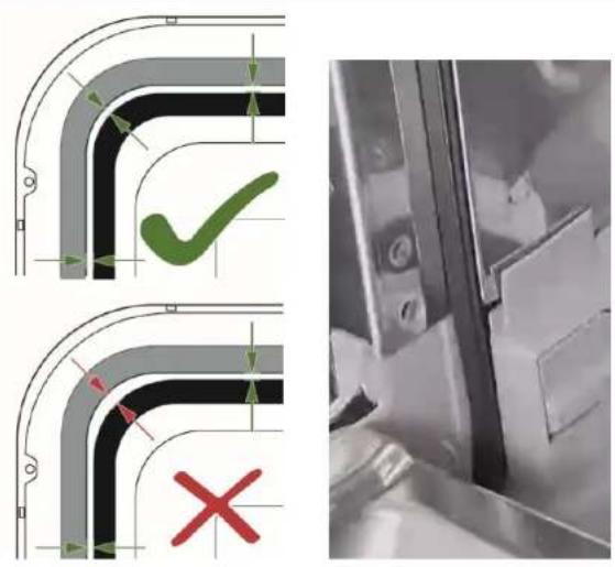
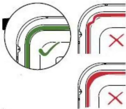
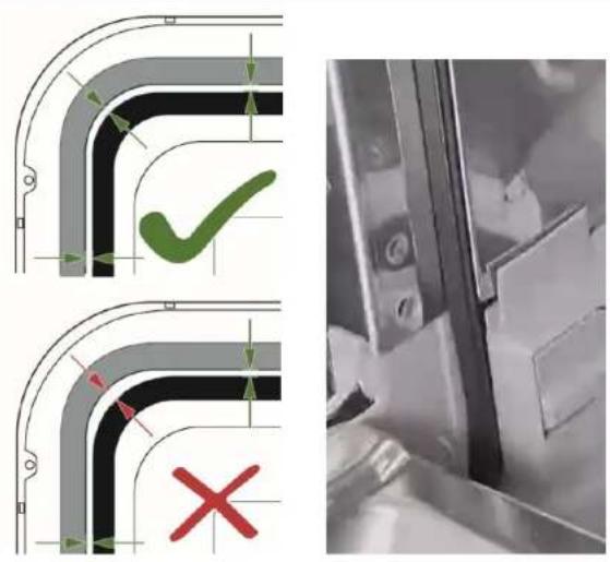
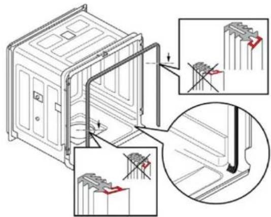
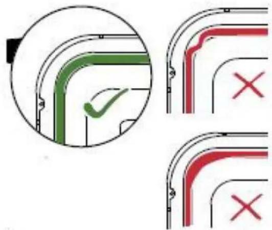
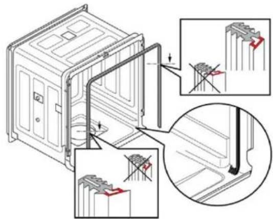
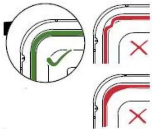
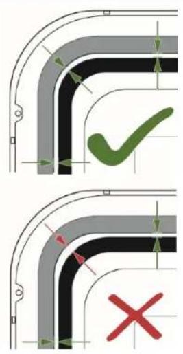
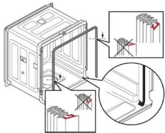
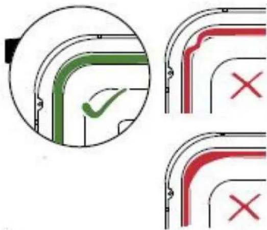
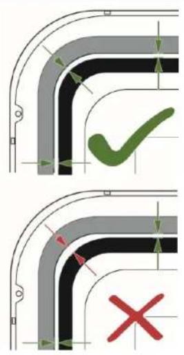
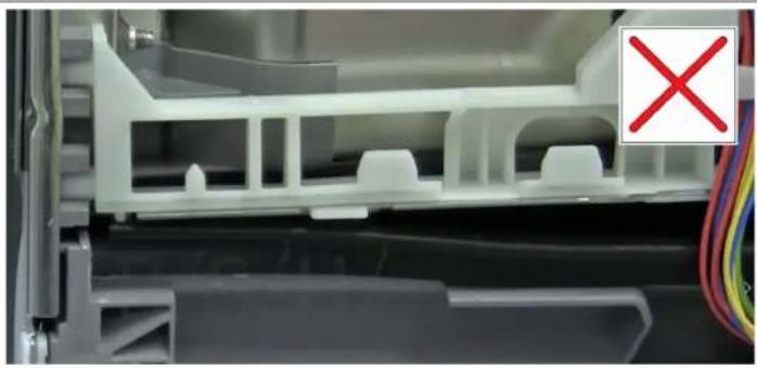
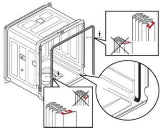
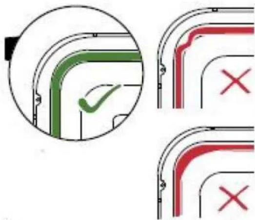
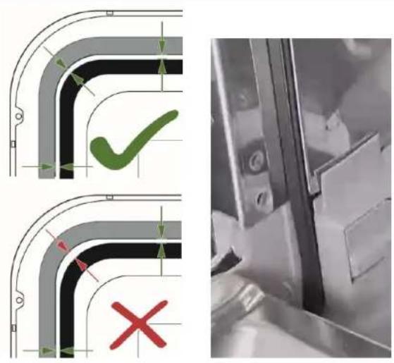
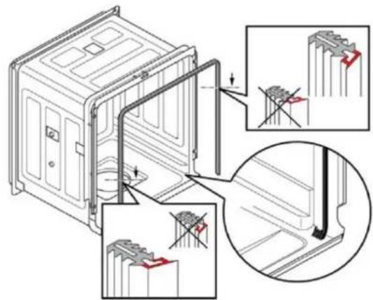
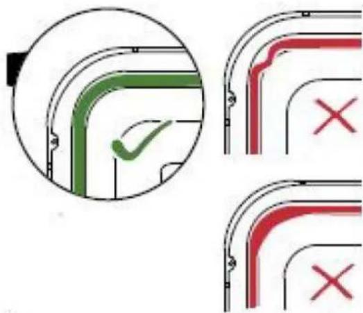
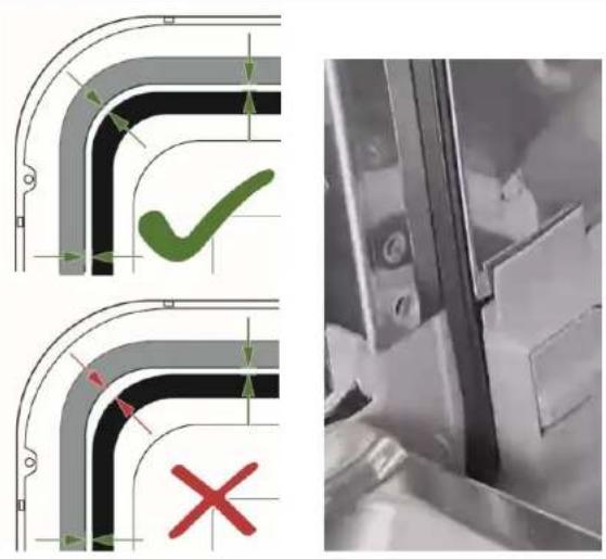
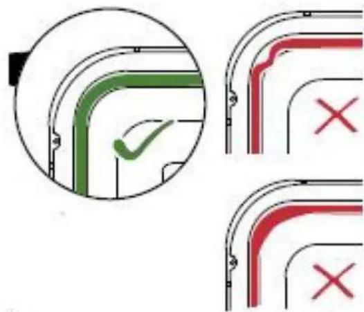
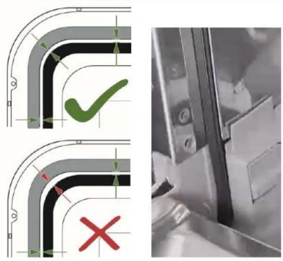
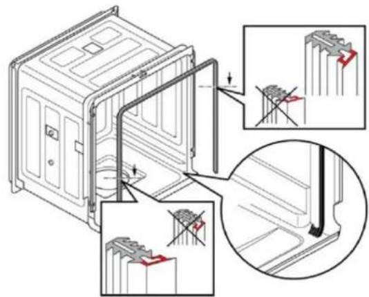
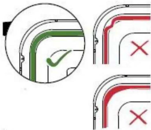
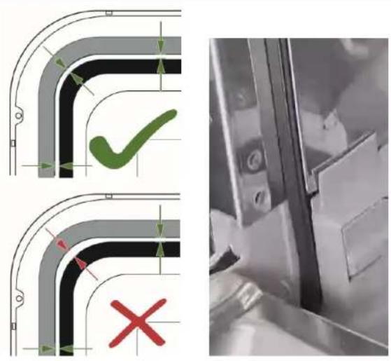
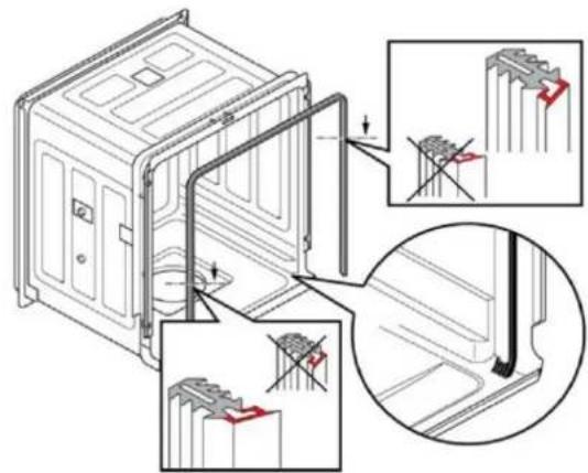
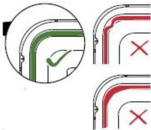
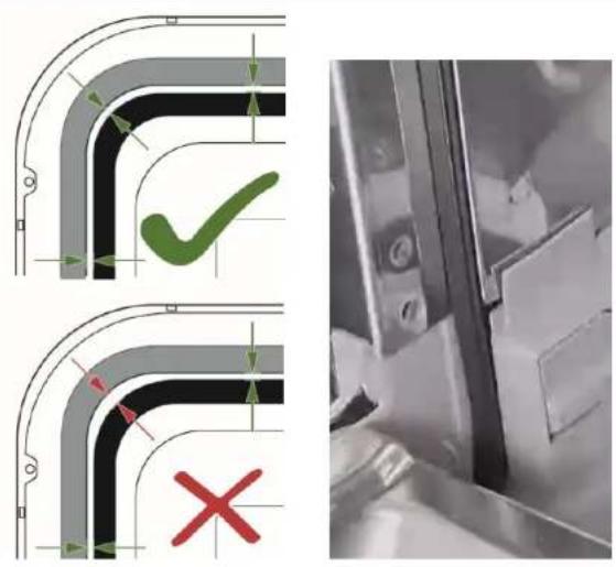
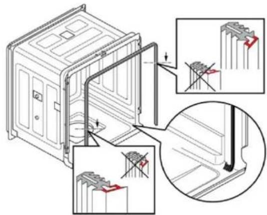
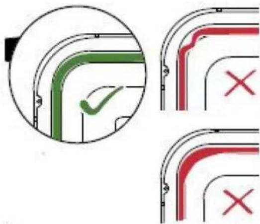
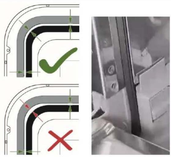
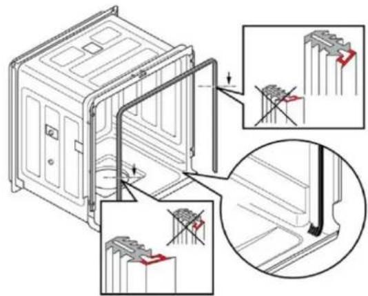
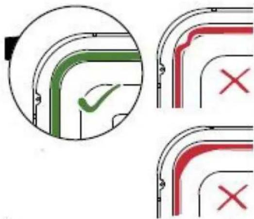
Make sure that the profile of the door seal is in the correct position.

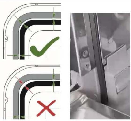
Make sure that the corners are not bent or twisted.

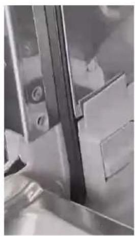
Place the end of the seal straight forwards, below the inner door. The seal should rest on the side of the tub as much as possible.

Technical diagram showing pipe connection and safety symbols with crosshair indicators.

Technical diagram showing mechanical assembly steps with magnified views highlighting structural changes.

Diagram showing three stages of a vehicle door with checkmark and red X marks indicating failure or rejection status.

SIEMENS SC05IB00TE - Install the door seal - 4

4.11 Replace the lower cover

Prerequisite

Appliance is disconnected from the mains.

Appliance is disconnected from water supply.

4.11.1 Remove the lower cover

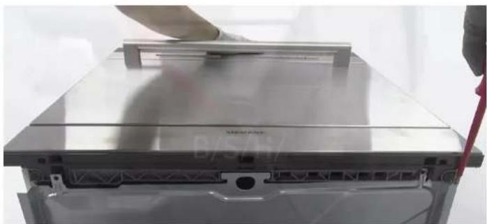
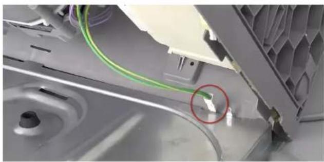
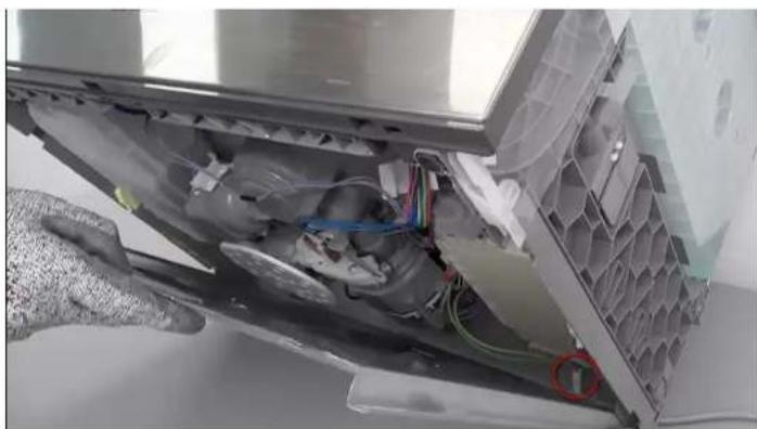
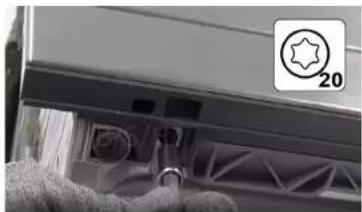
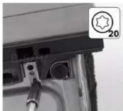
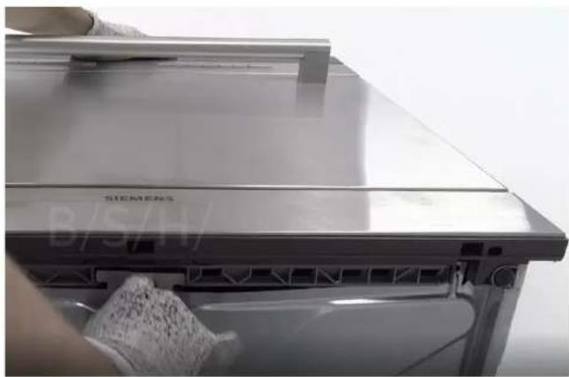
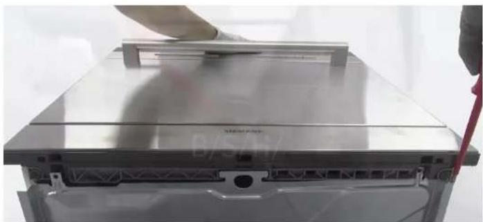
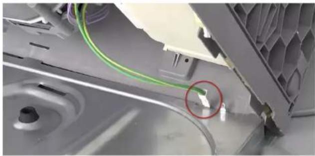
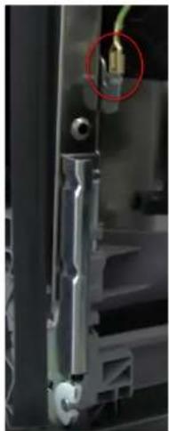
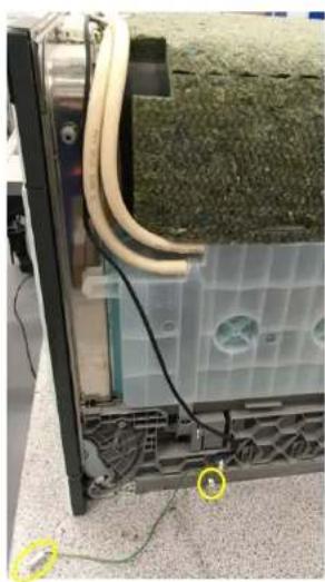
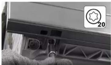
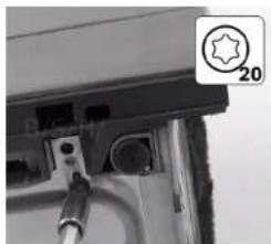
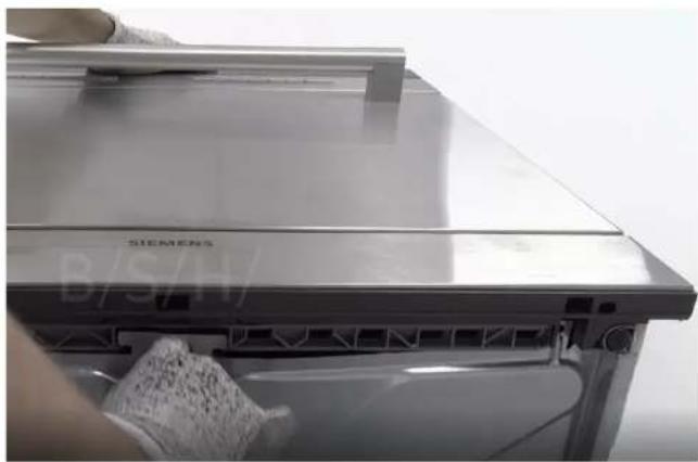
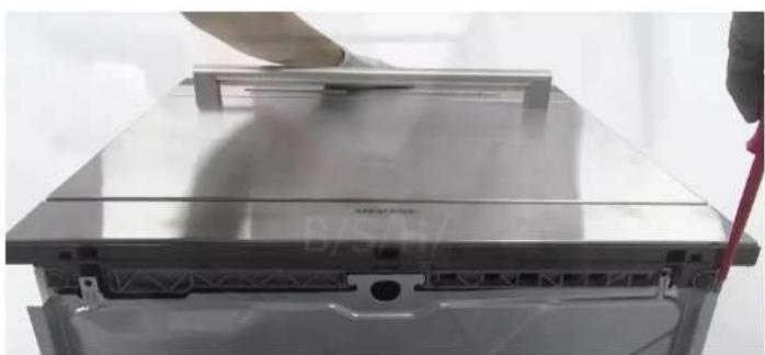
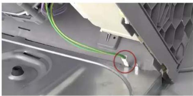
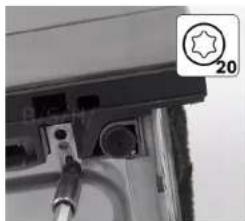
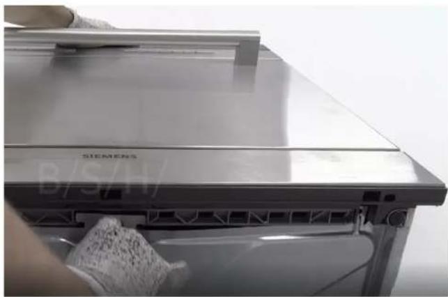
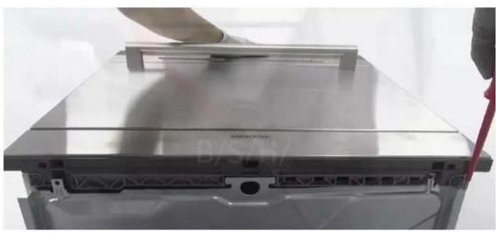
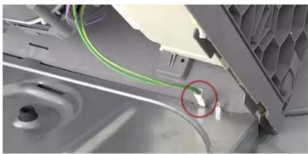
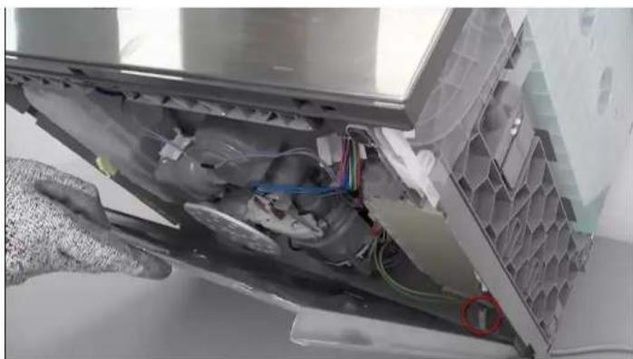
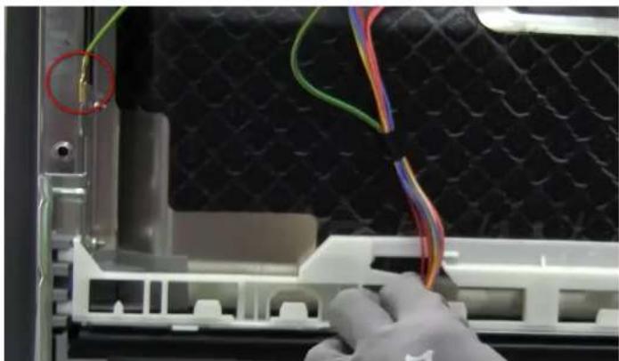
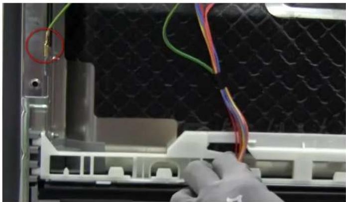
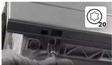
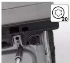
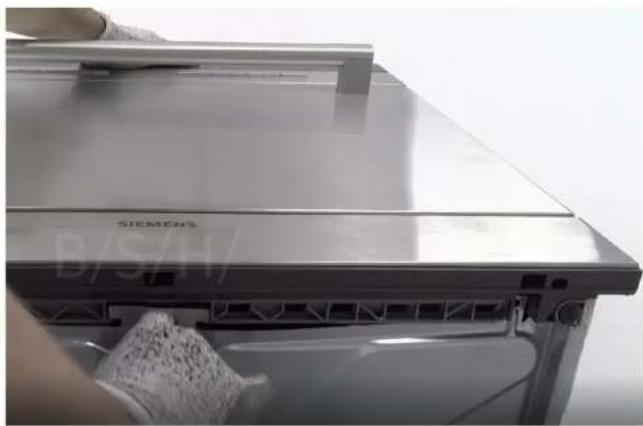
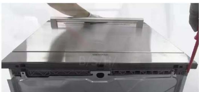
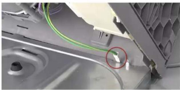
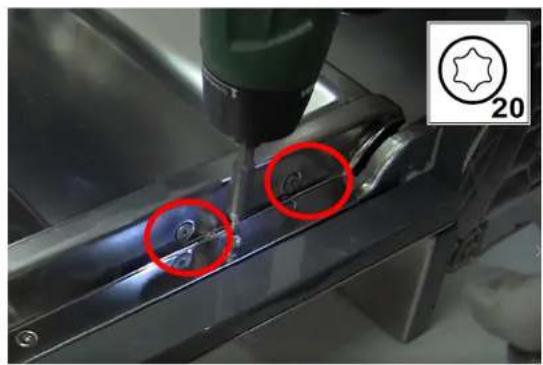
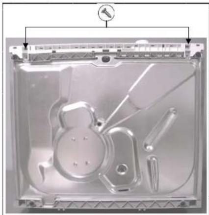
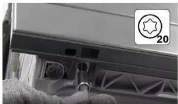
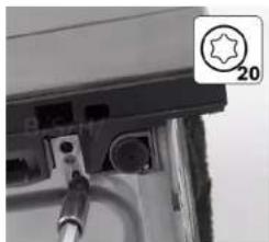
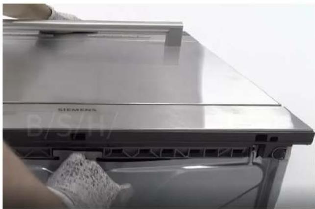
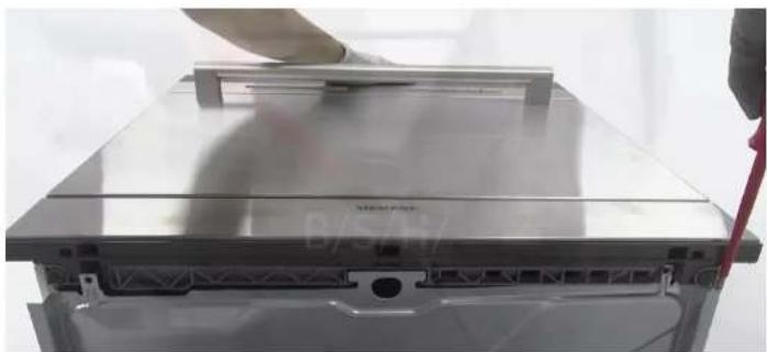
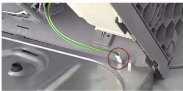
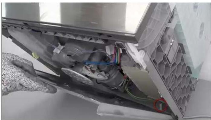
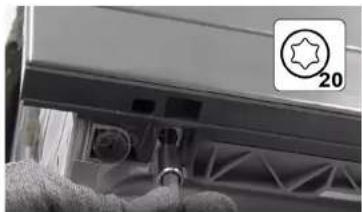
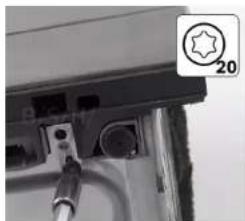
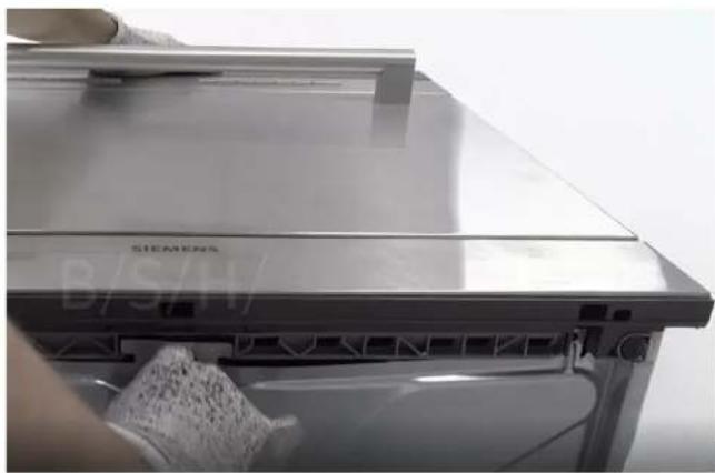
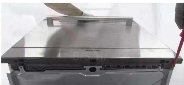
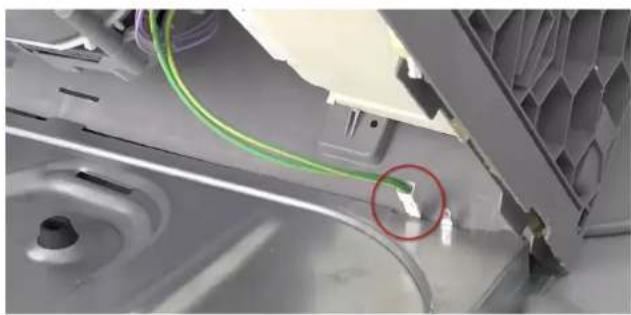
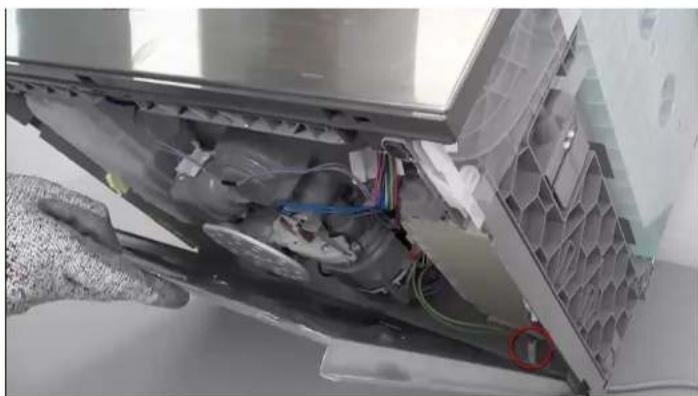
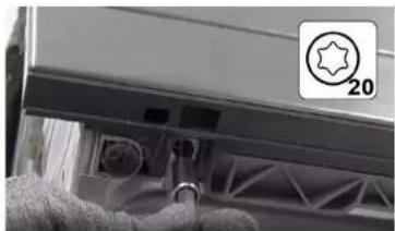
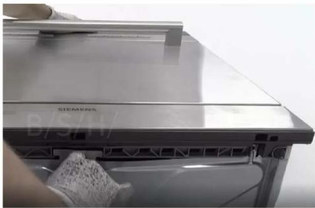
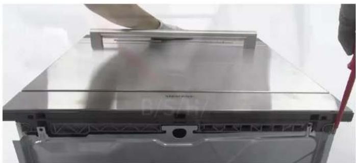
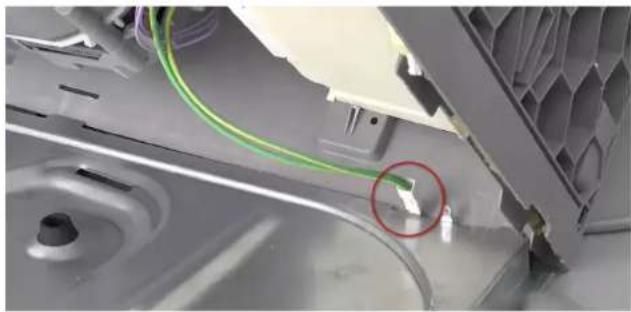
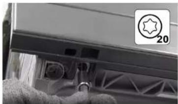
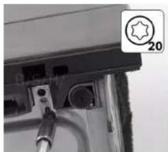
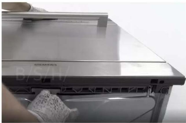
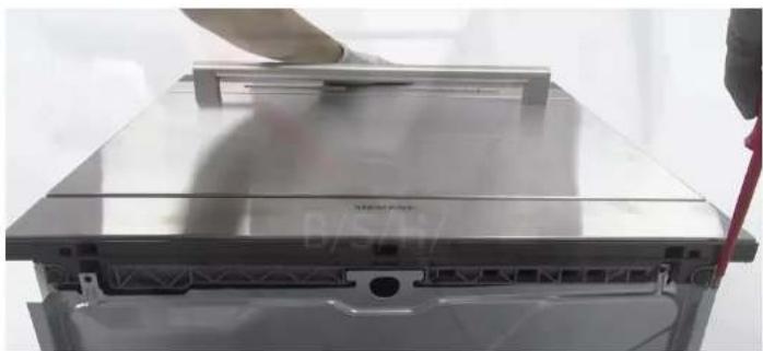
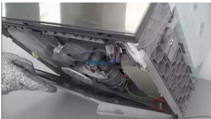
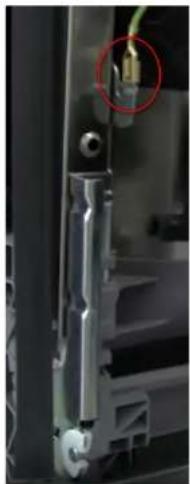
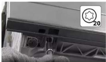
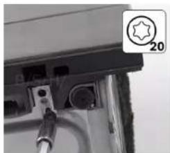
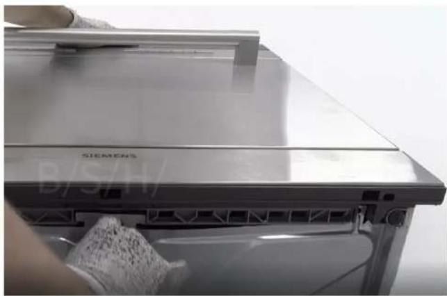
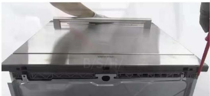
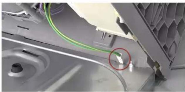
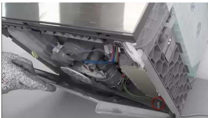
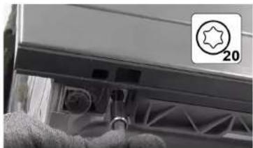
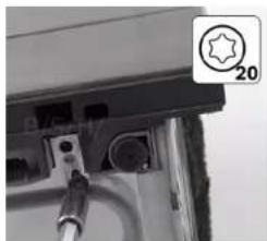
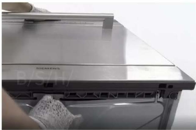
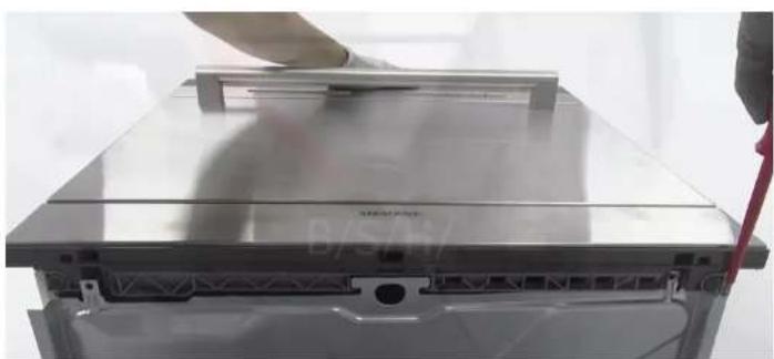
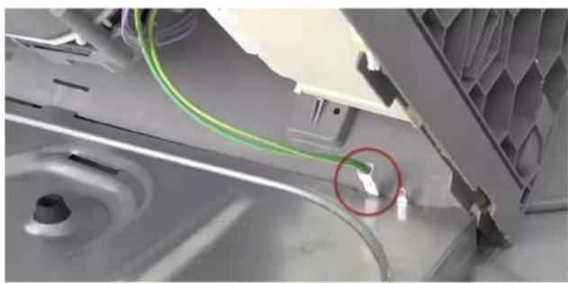
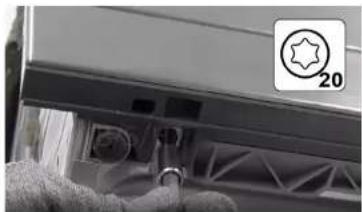
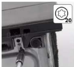
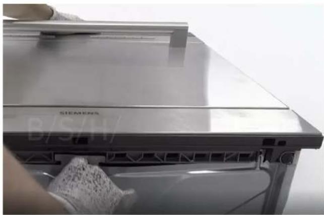
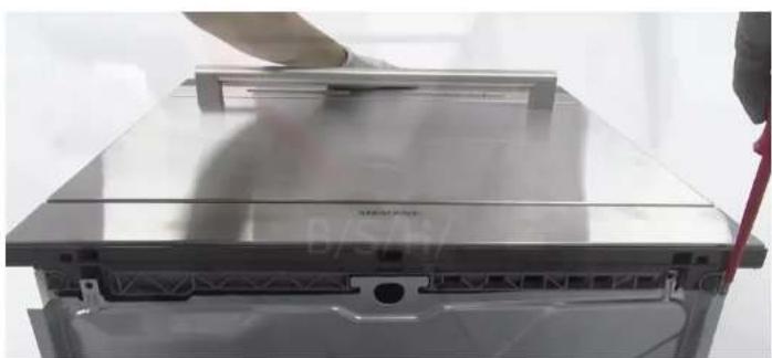
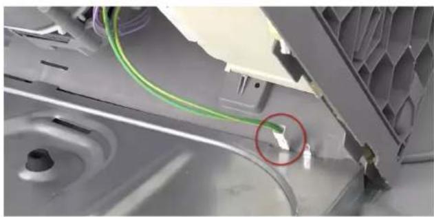
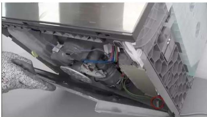
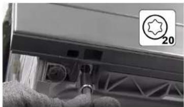
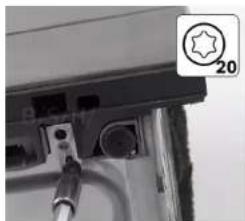
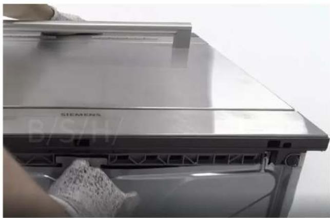
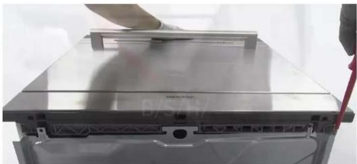
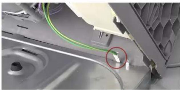
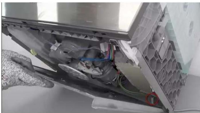
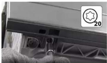
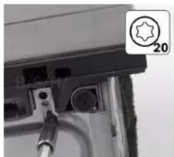
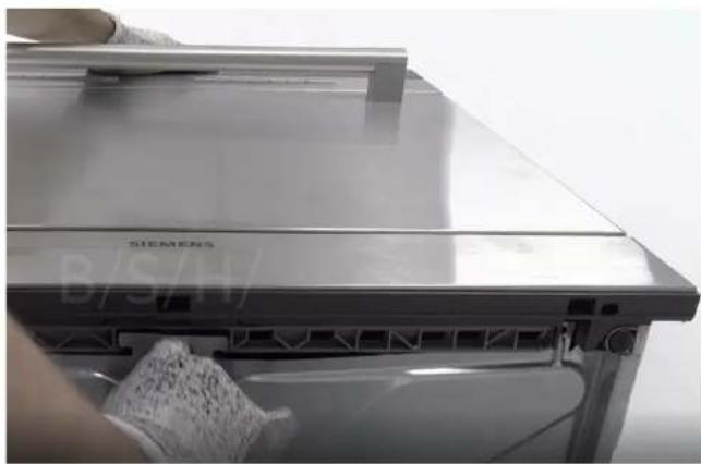
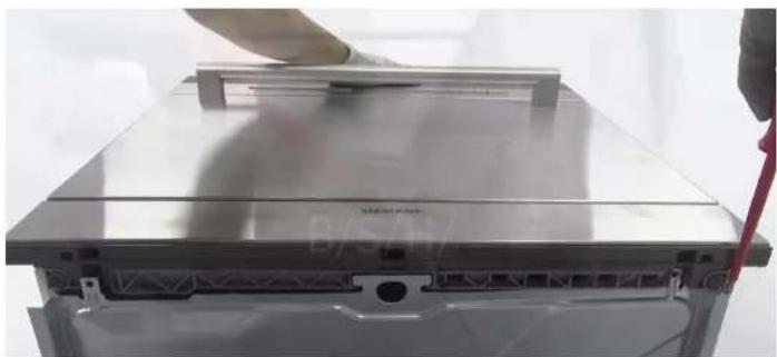
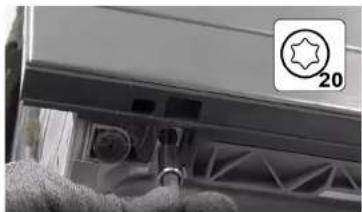
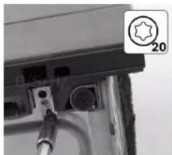
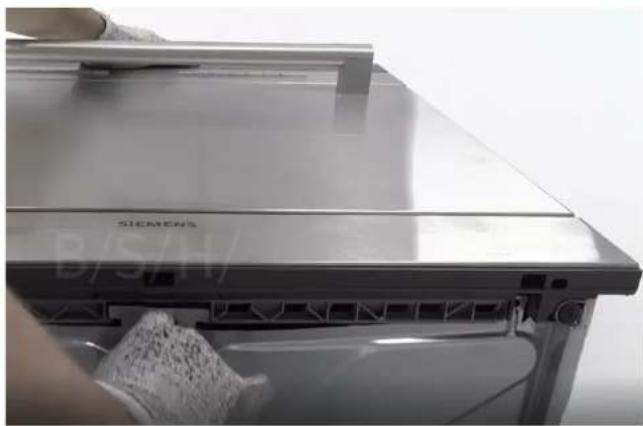
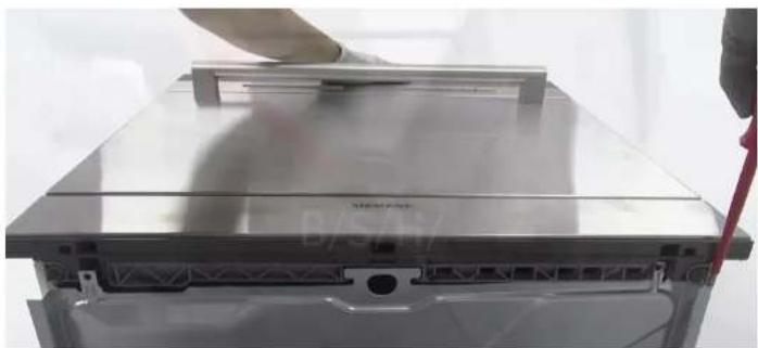
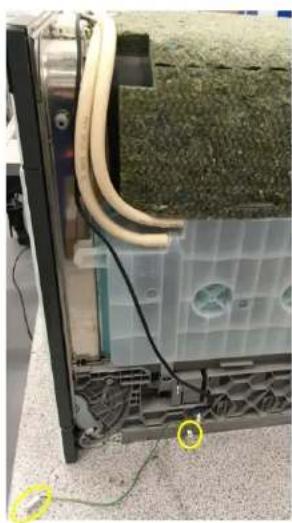
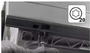
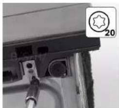
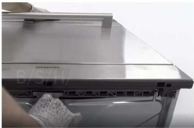
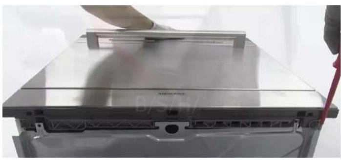
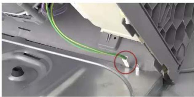
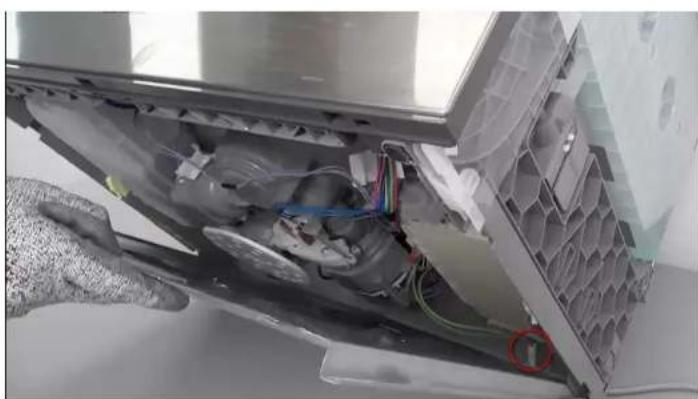
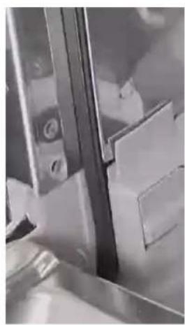
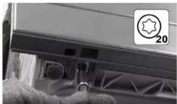
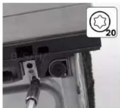
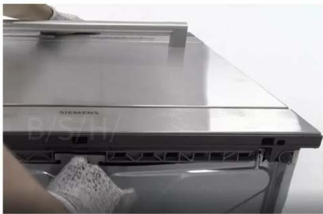
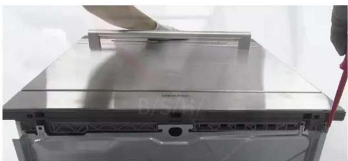
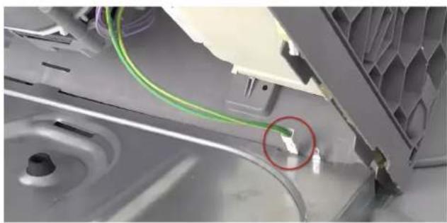
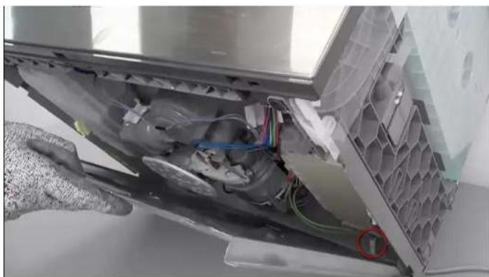
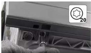
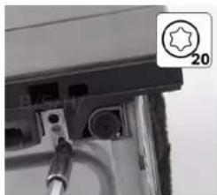
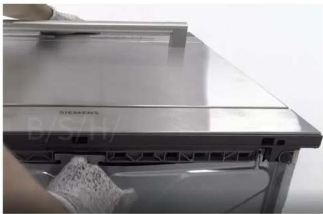
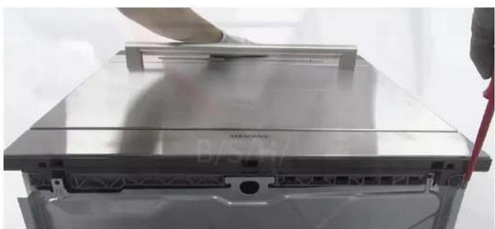
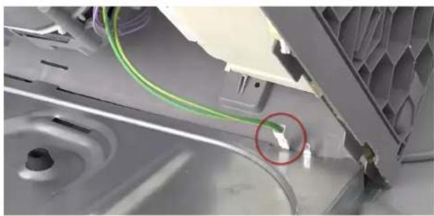
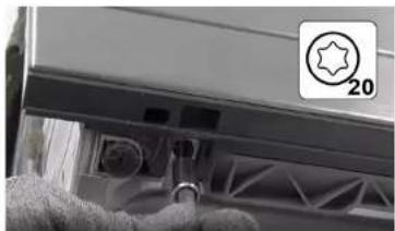
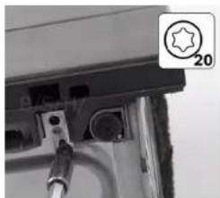
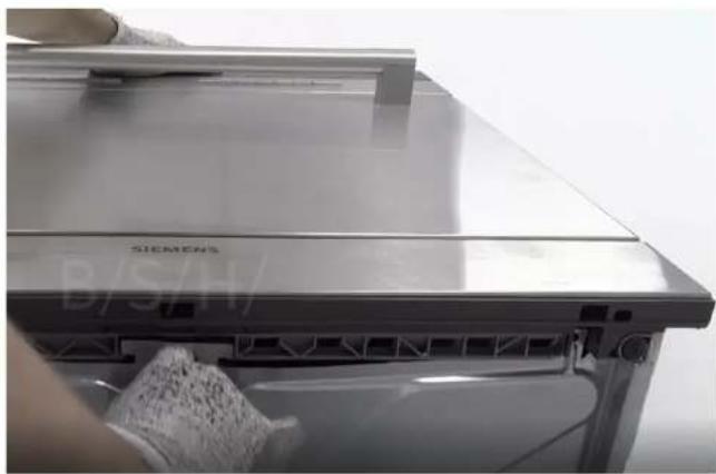
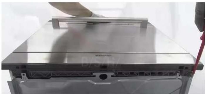
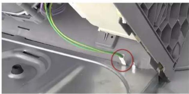
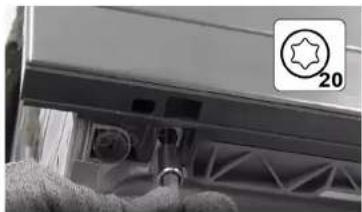
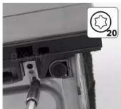
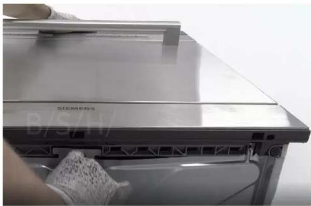
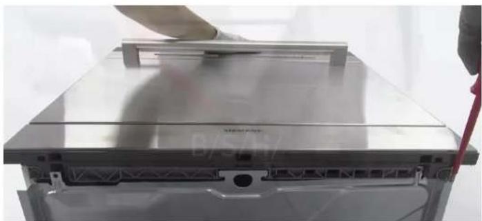
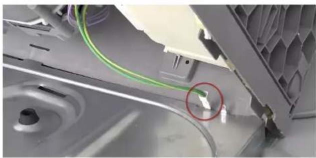
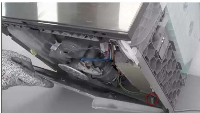
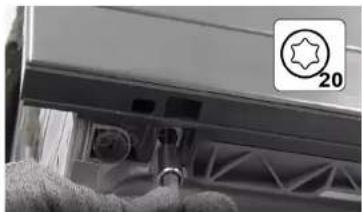
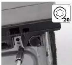
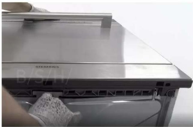
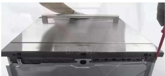
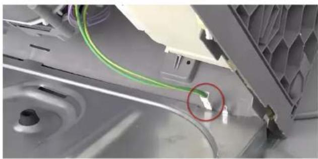
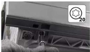
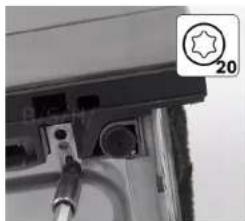
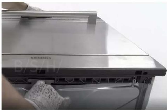
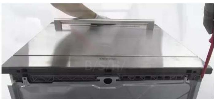
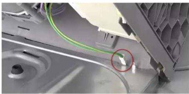
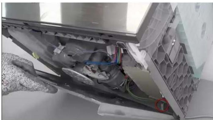
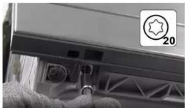
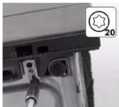
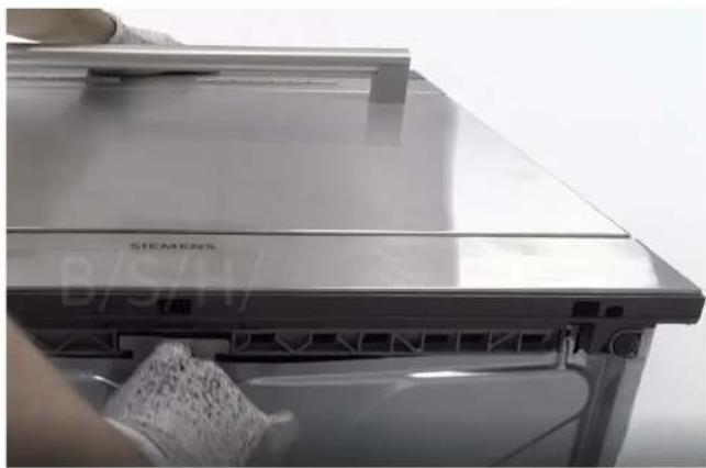
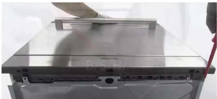
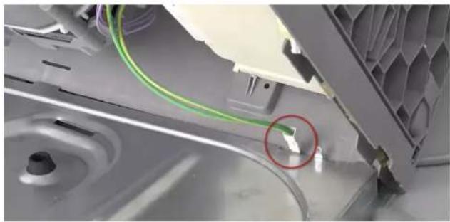
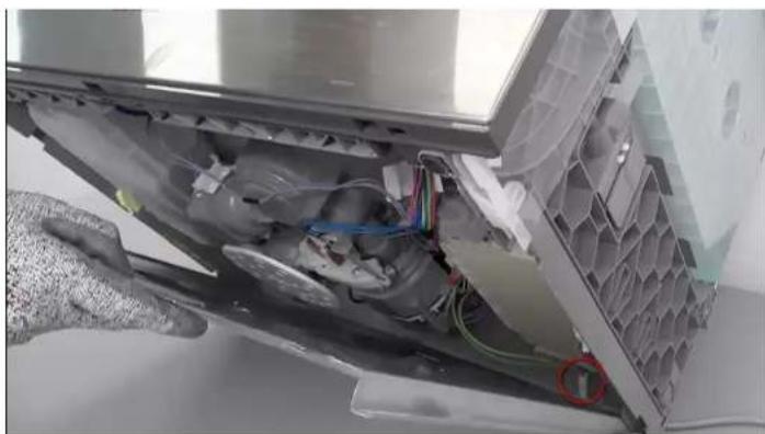
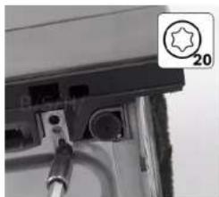
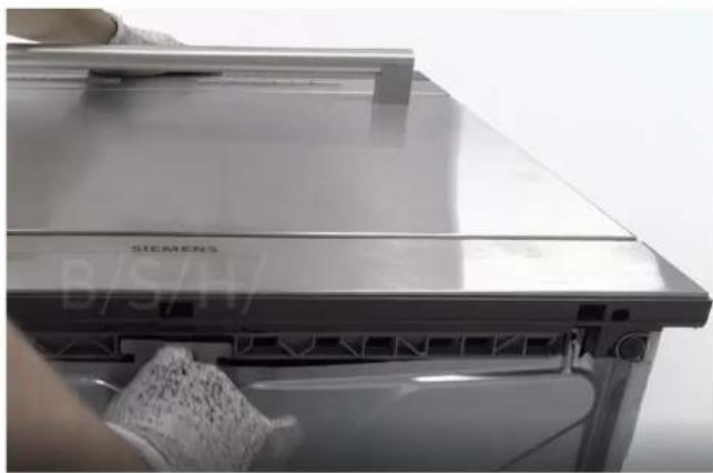
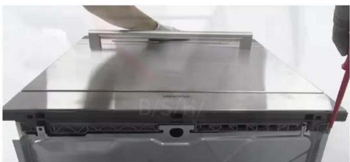
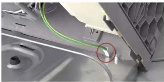
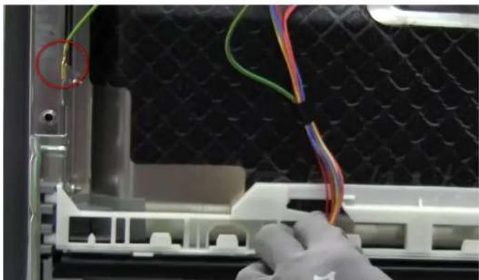
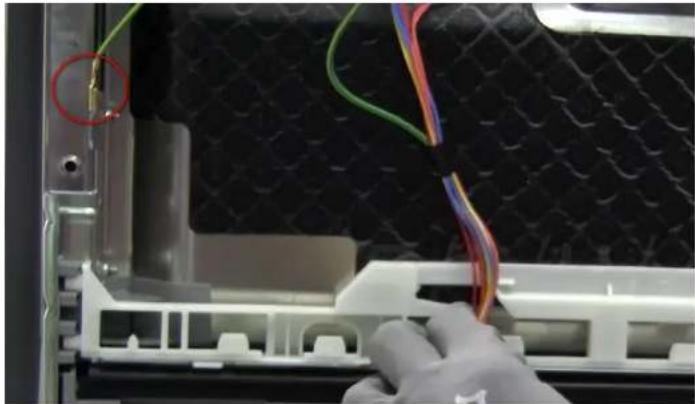
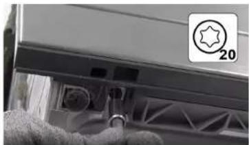
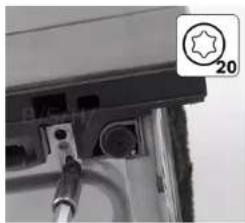
1 Unscrew the two torx 20 retaining screws. 2 Pull from the lower hole until it is free from the fixing pin. Use a slotted screwdriver to detach on both sides. 3 Detach the earth wire.

Interior view of a refrigerator with visible door, wheels, and ventilation slots (no text or symbols).

Close-up of a mechanical component with a star-shaped emblem and number 20, no visible text or symbols on the main subject.

Close-up of a mechanical component with a gear and a star-shaped badge labeled '20' (no readable text or symbols beyond the badge).

Close-up of a stainless steel kitchen appliance with a hand cleaning the lid (no visible text or symbols).

Close-up of a silver computer drive chassis with a hand adjusting its top panel (no visible text or symbols).

Close-up of a mechanical device showing internal components with a green cable and a red circle highlighting a small green component (no text or symbols visible).

Close-up of an air conditioner unit showing internal components and wiring (no text or symbols visible).

4.11.2 Assembly

1 Position the lower cover by inserting the protruding edges into the grooves in the tub's plastic base. 2 Install the earth wire in the base. 3 Screw in the two retaining screws.

Appliance is disconnected from the mains.

Appliance is disconnected from water supply.

Lower cover removed.

4.12.1 Disassembly

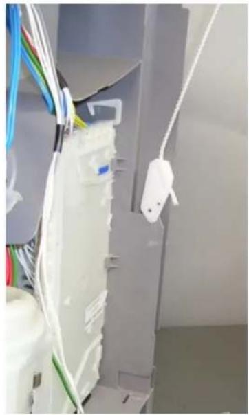
Interior view of an appliance enclosure showing wiring and a white plastic bag (no visible text or symbols).

  1. Rest the rope's plastic holder on the protruding edge of the plastic base.
  2. Use a screwdriver to detach the rope from the hinge.
  3. When the rope is detached, the spring can be removed.

Close-up of a gloved hand using a tool to adjust or install a mechanical component, with no visible text or symbols.

4.12.2 Assembly

Assemble in reverse order.

SIEMENS SC05IB00TE - Assembly - 1

Holder

The rope holder is automatically released from its position when the door is closed.

4.12.3 Door hinge springs

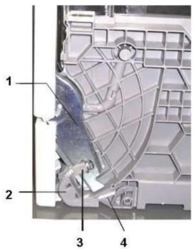
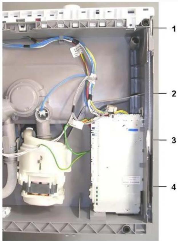
The appliance has two springs that control the opening and closing force of the dishwasher's door. They are on either side of the appliance.

The spring tension is transmitted via a rope to the hinge, through a plastic tensioner.

The spring's tension force cannot be adjusted.

The spring and transmission system automatically adapt to the door weight.

1 2 3 4

1 Hinge 2 Sheave 4 Rope 3 Rope attachment piece

Internal wiring diagram of an electrical enclosure with numbered components and visible wiring connections.

1 Sheave 2 Rope 4 Tension spring 3 Plastic holder

4.13 Replace hinge

Prerequisites:

Appliance is disconnected from the mains.

Appliance is disconnected from water supply.

Remove the outer and inner doors.

Remove the lower cover.

Detach the cabinets.

4.13.1 Remove the hinge

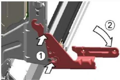
Use a screwdriver (1) to release the latch.

Pull outwards (2).

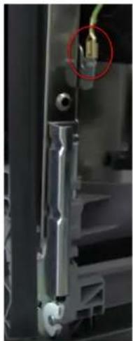
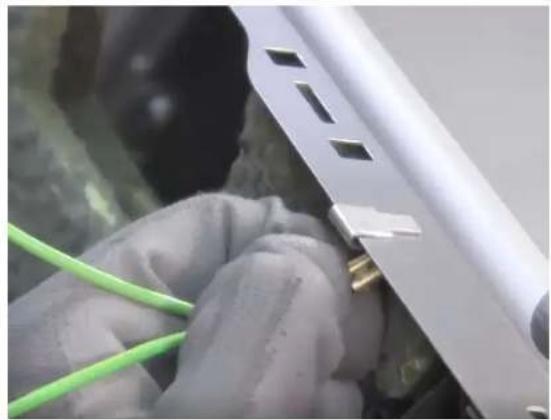
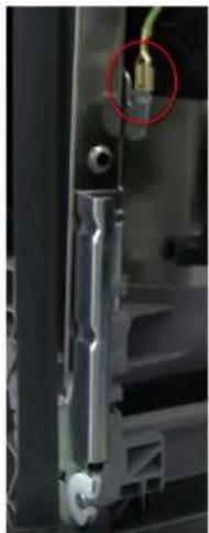
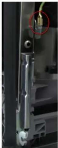
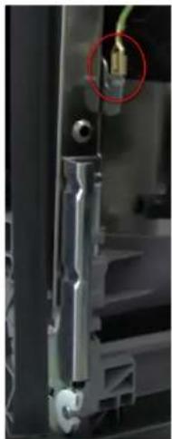
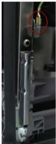
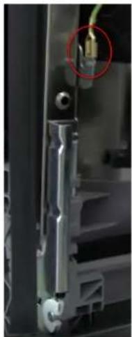
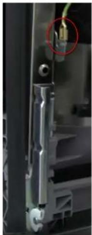
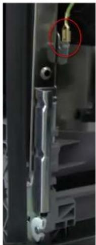
Disconnect the earthing connection from the hinge.

Mechanical assembly diagram showing two labeled parts (① and ②) with directional arrows indicating movement or force, no readable text or symbols present.

Close-up of a mechanical component with a red circle highlighting a small connector.

Close-up of a gloved hand adjusting a 3D printer's cable and plastic component.

4.13.2 Install the hinge

SIEMENS SC05IB00TE - Install the hinge - 1

SIEMENS SC05IB00TE - Install the hinge - 2

DANGER

Electric shock hazard due to live parts

Risk of injury from electrocution and response to shock.

Electrical components should be repaired by a qualified electrician. After the repair, ensure that a safety test is performed in accordance with standard VDE 0701 or the country's specific standards.

Position the hinge on the appliance (1).

Move the hinge downwards (2) until it fits onto the appliance.

Connect the hinge's earth wire.

SIEMENS SC05IB00TE - Electric shock hazard due to live parts - 1

A missing earthing connection can lead to voltage at the door.

Technical diagram showing mechanical assembly with labeled parts and directional arrows indicating motion or movement.

Close-up of a gloved hand inserting wires into a black textured device component.

4.14 Replace the emotion light

SIEMENS SC05IB00TE - Replace the emotion light - 1

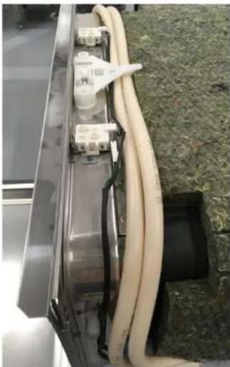
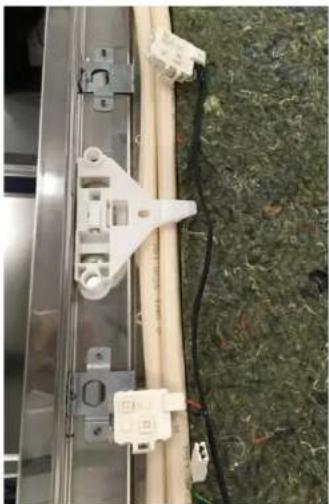
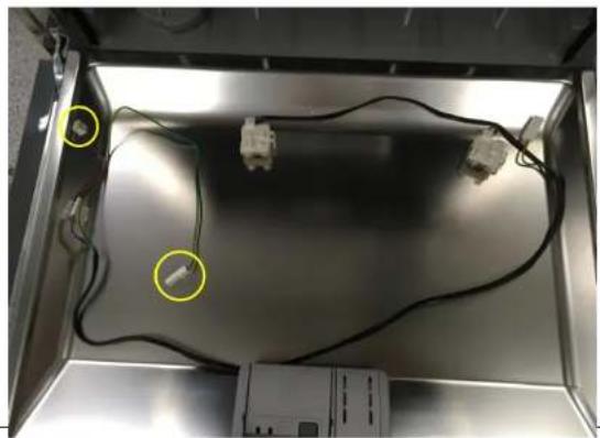
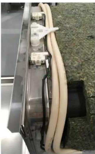
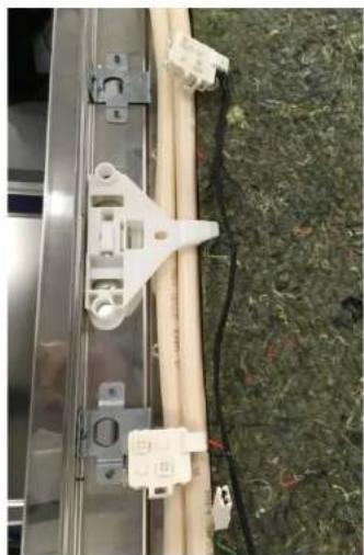
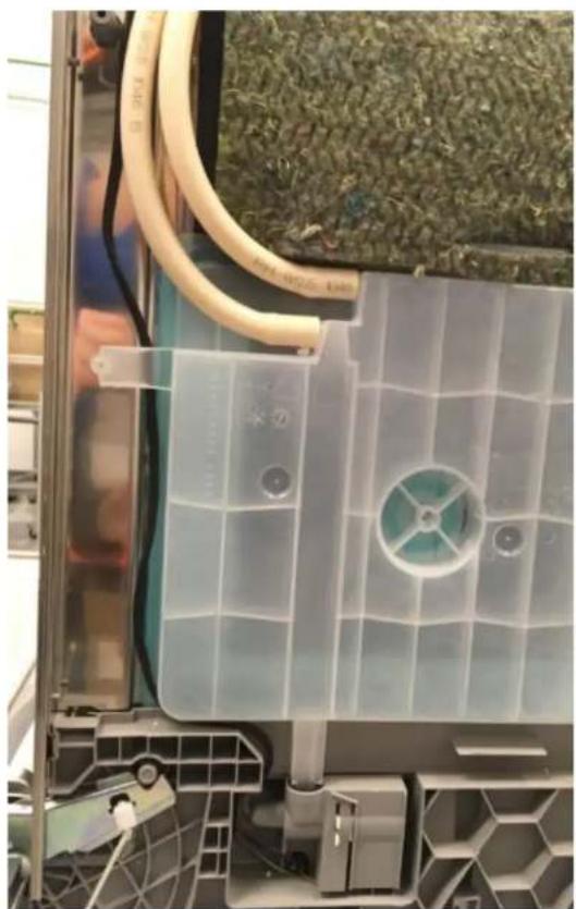
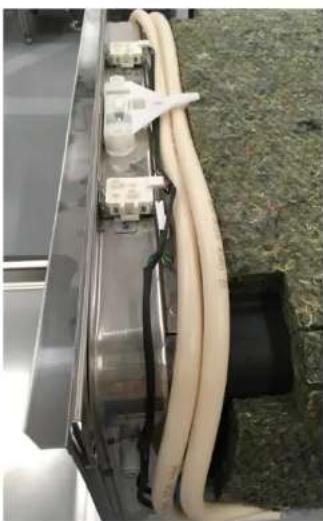
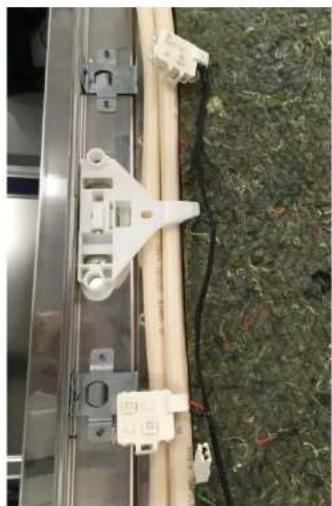
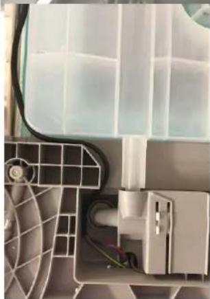
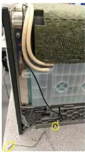
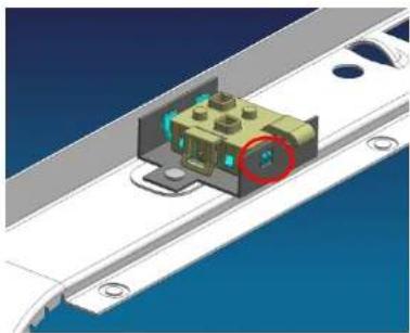
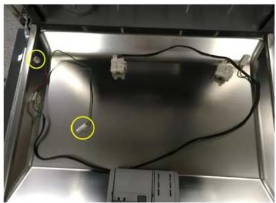
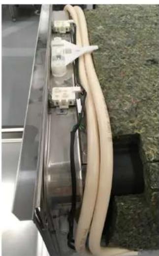
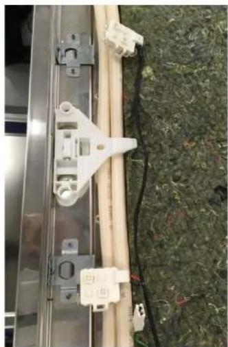
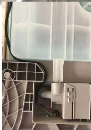
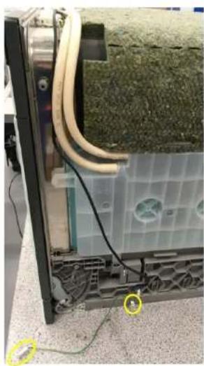
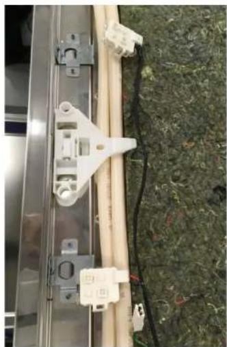
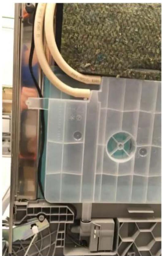
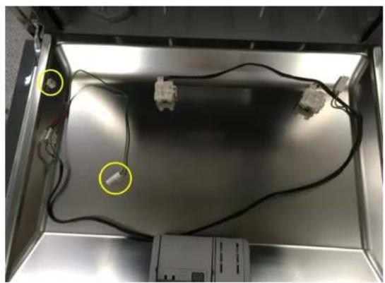
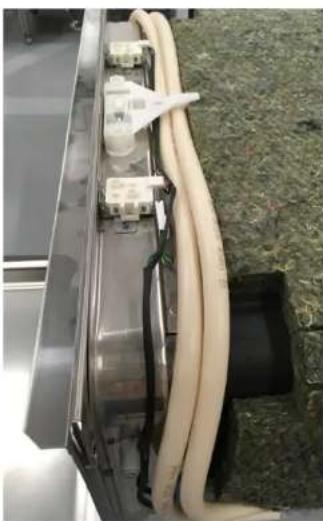
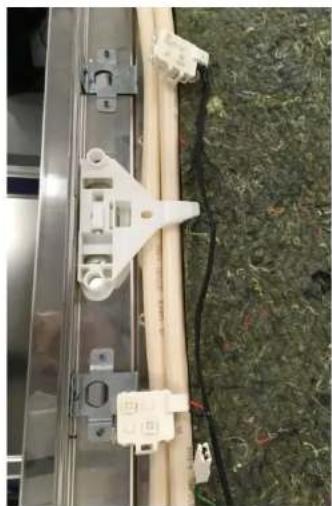
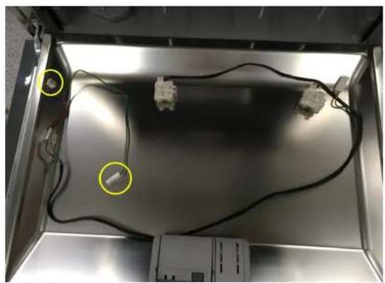
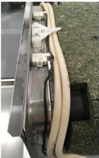
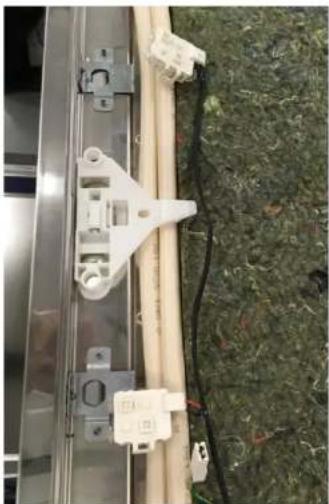
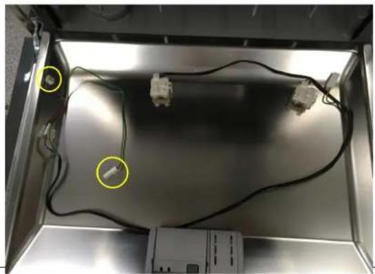
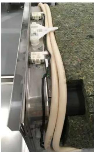
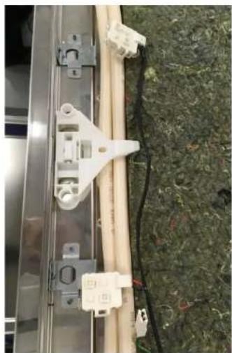
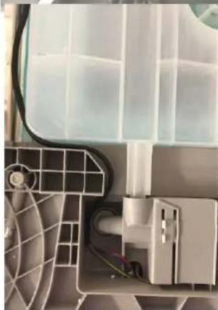
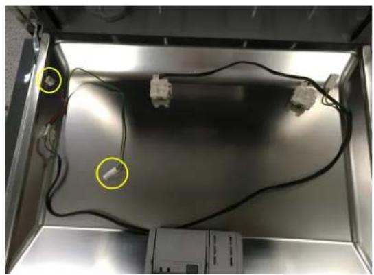
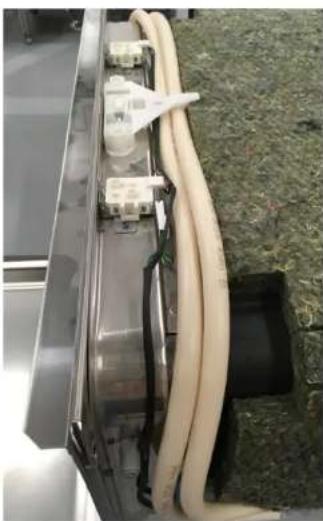
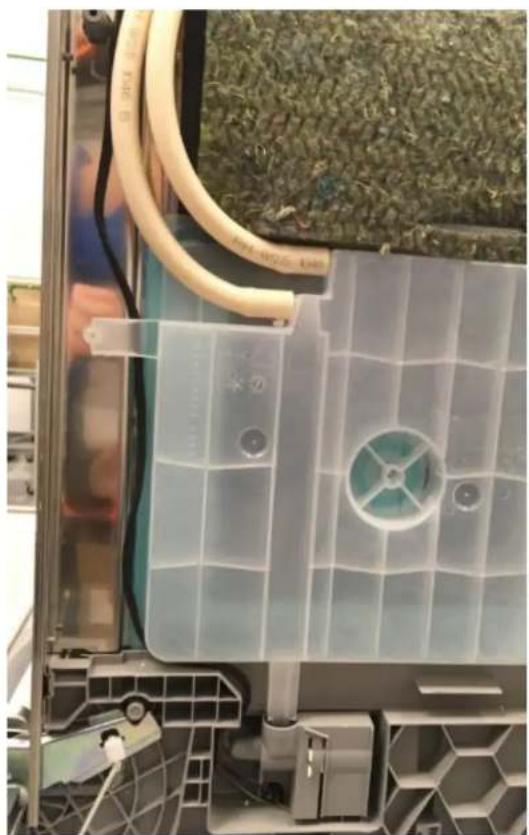
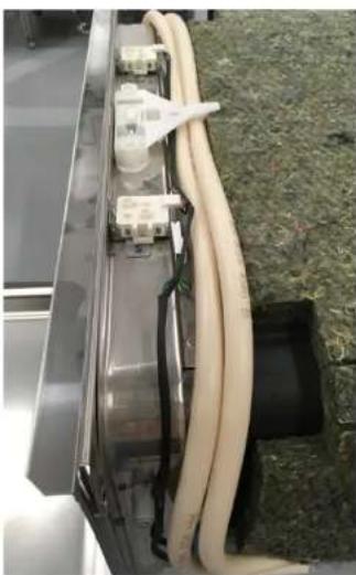
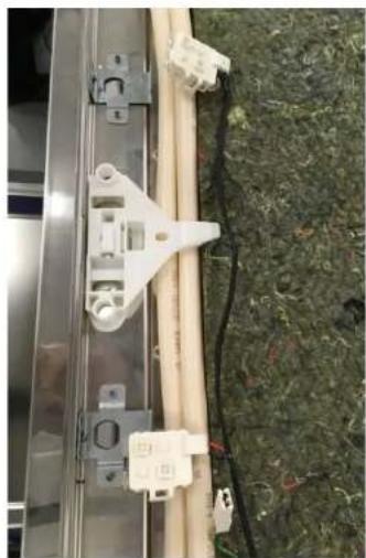
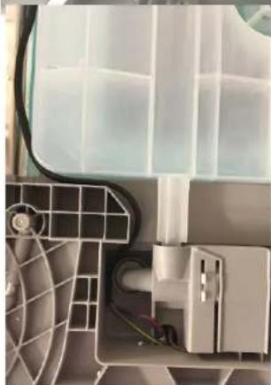
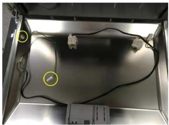
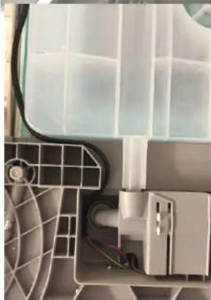
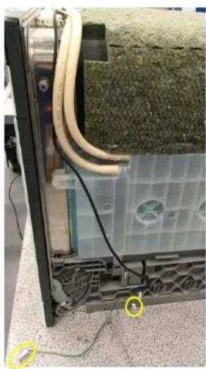
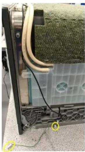
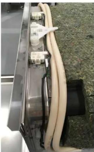
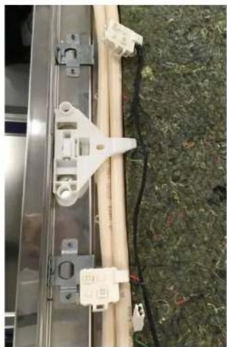
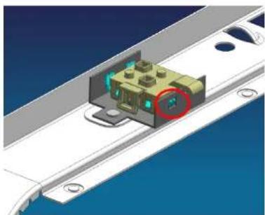
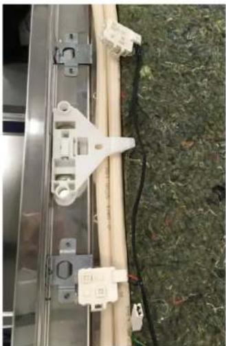
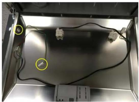
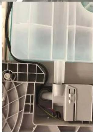
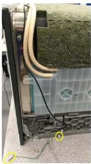
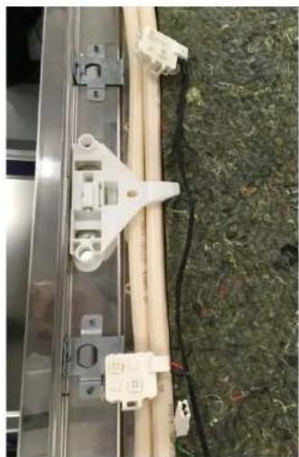
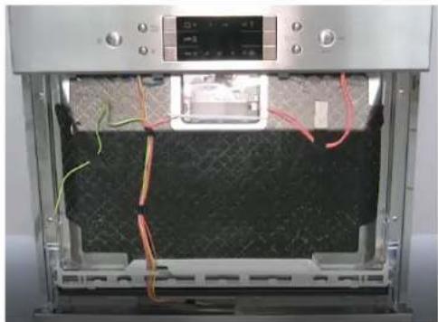
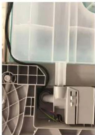
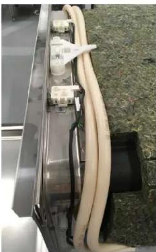
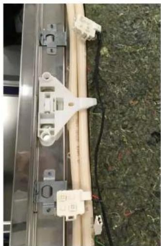
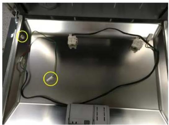
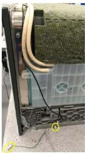
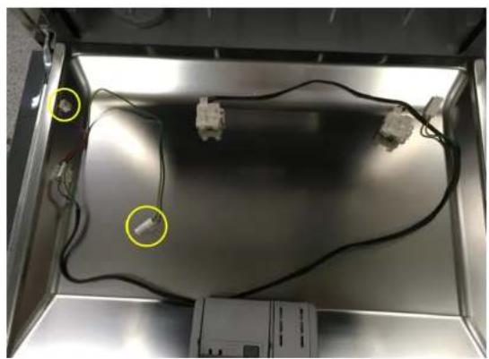
The Emotion Light is in the upper front outer area of the tub. The two lights are with the cable harness and they connect to the power module.

Prerequisites

Appliance is disconnected from the mains.

Appliance is disconnected from water supply.

The lower cover has been removed.

4.14.1 Remove the emotion light

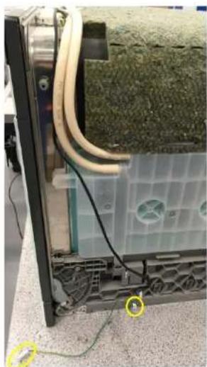
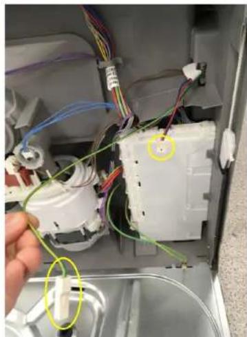
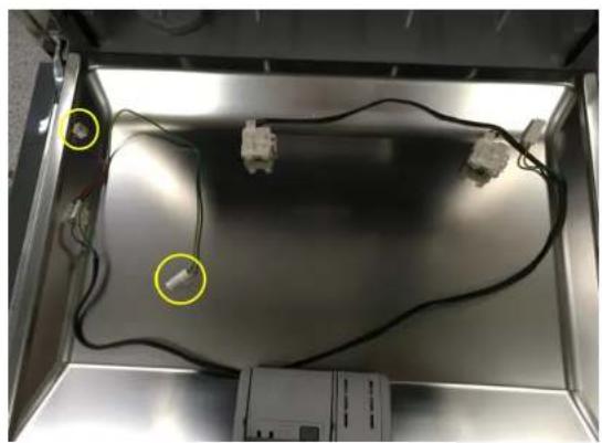
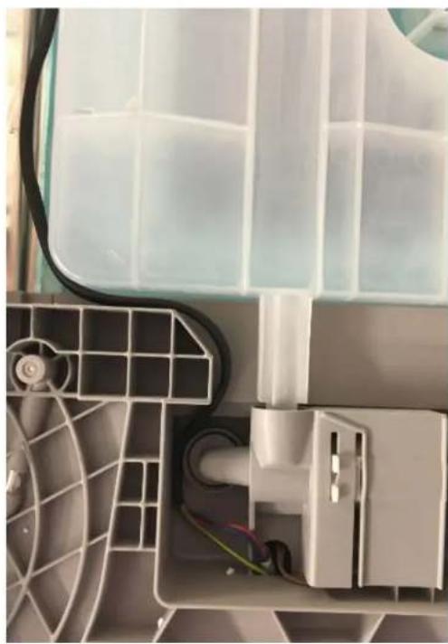
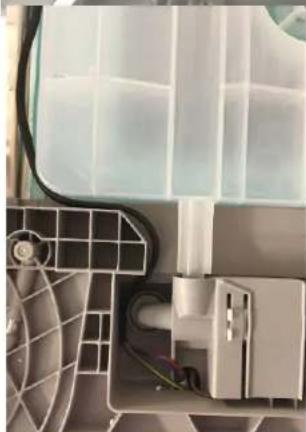
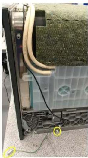
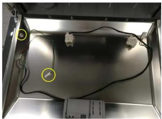
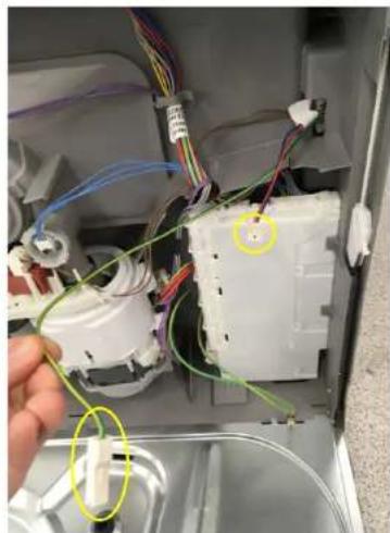
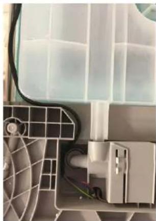
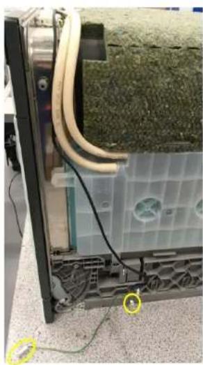
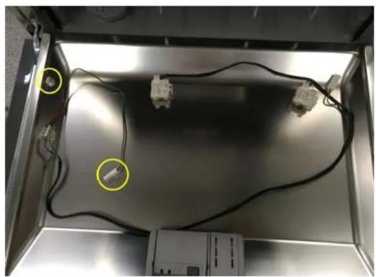
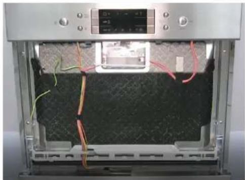
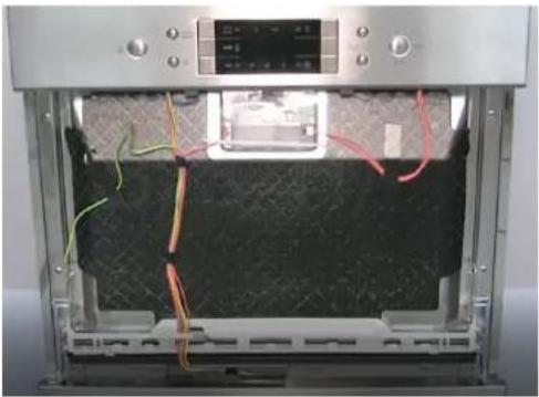
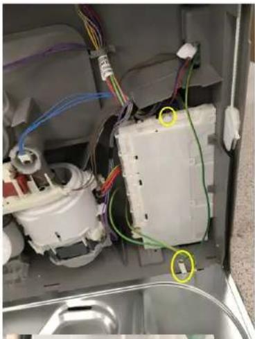
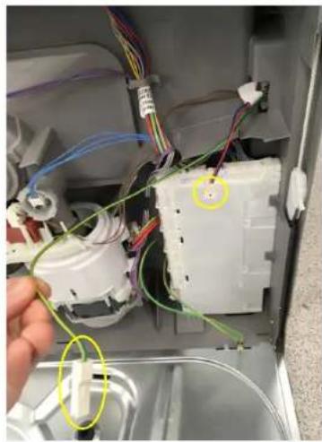
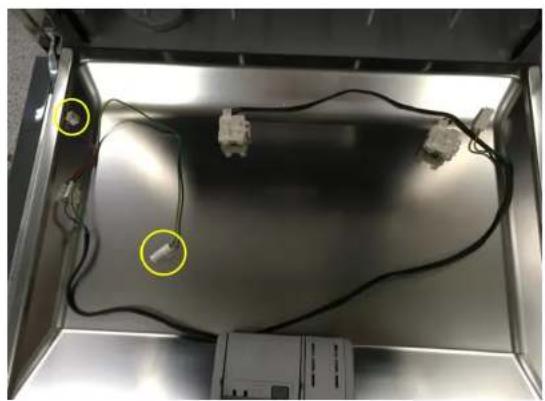
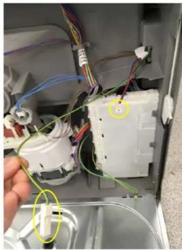
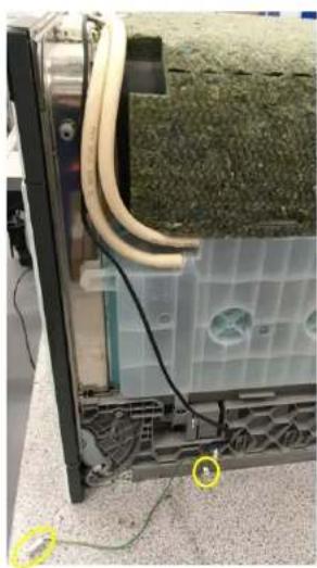
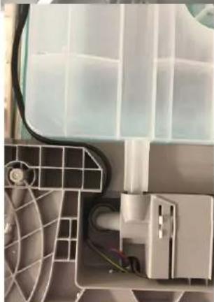
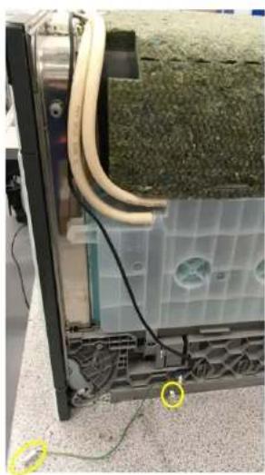
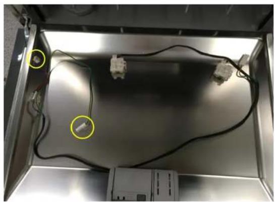
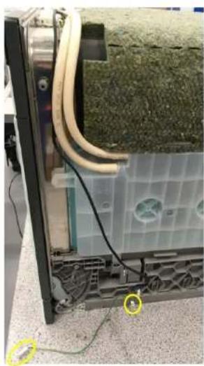
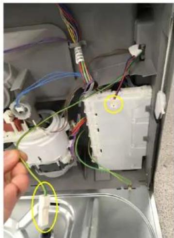
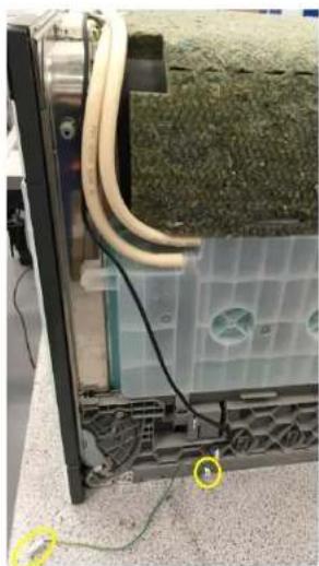
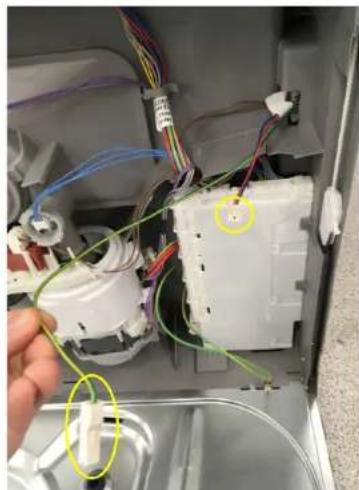
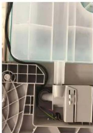
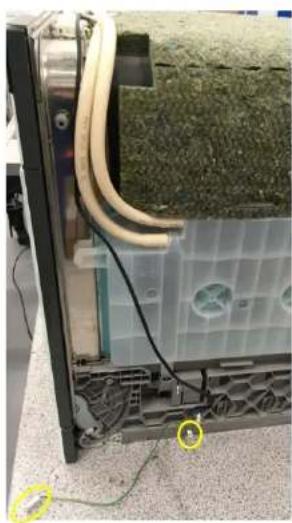
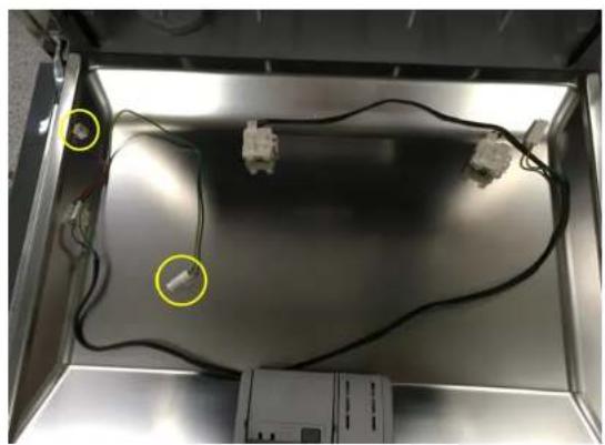
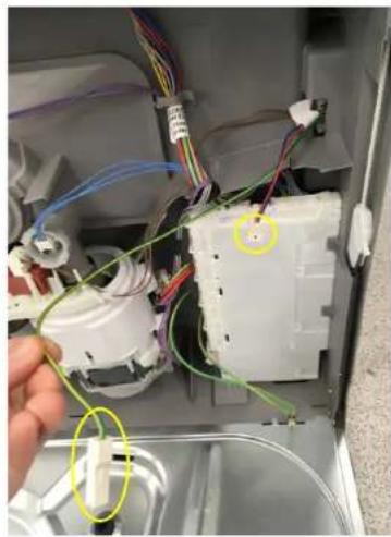
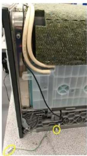
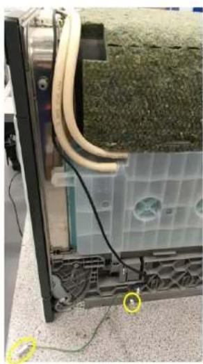
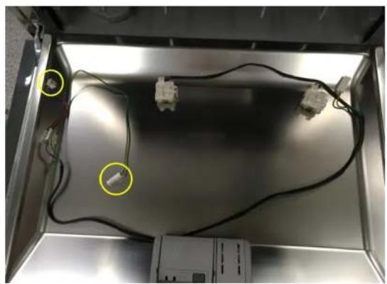
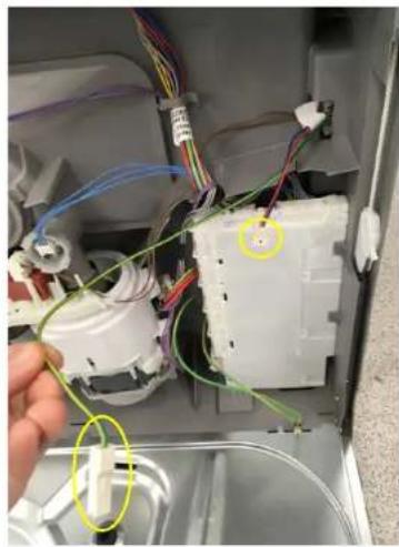
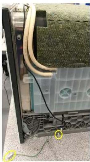
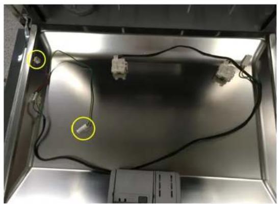
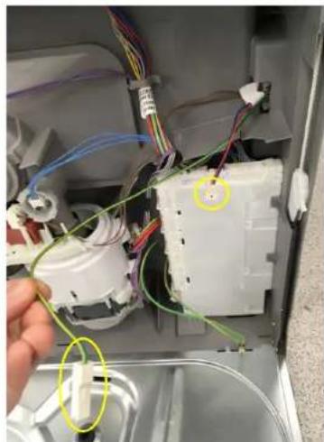
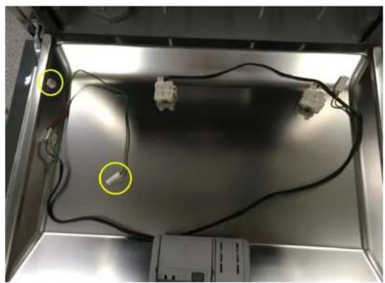
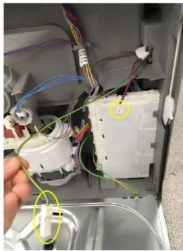
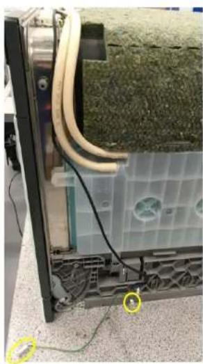
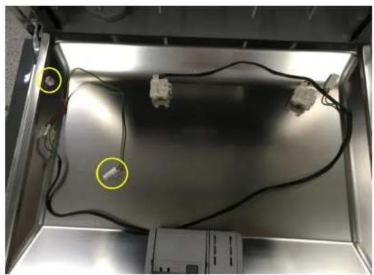
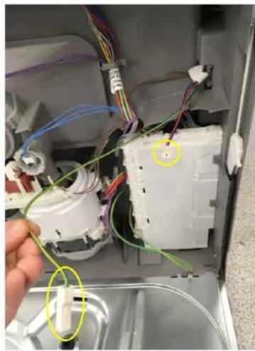
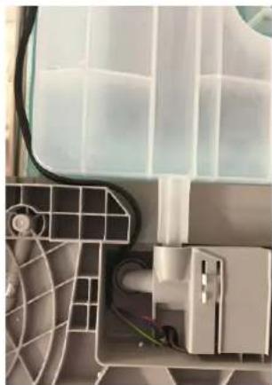
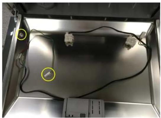
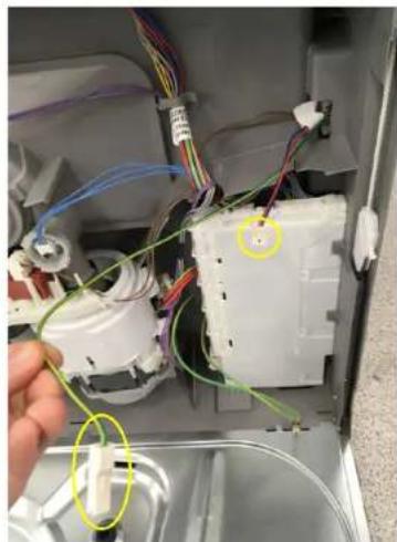
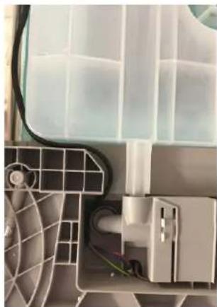
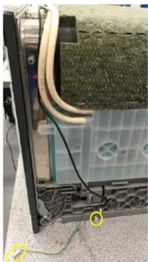
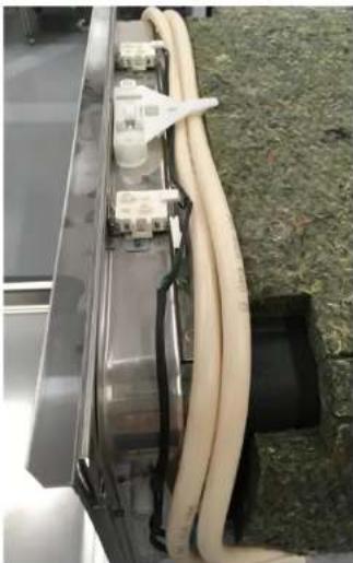
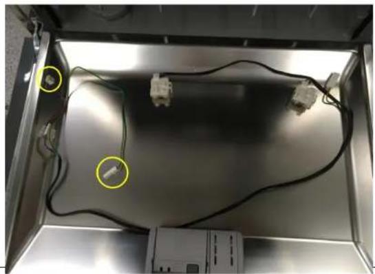
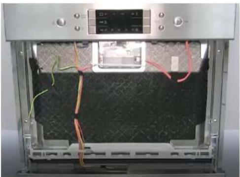
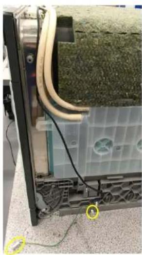
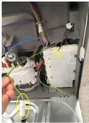
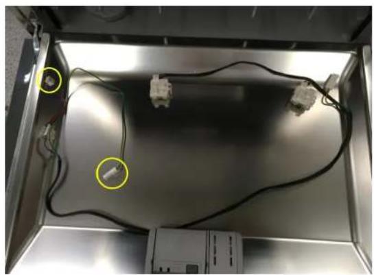
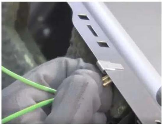
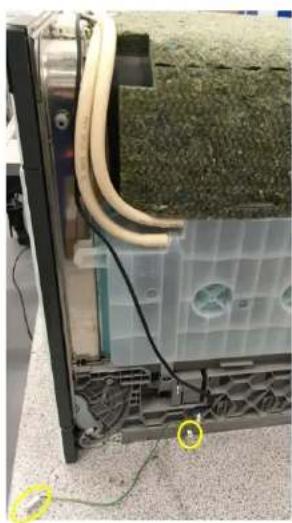
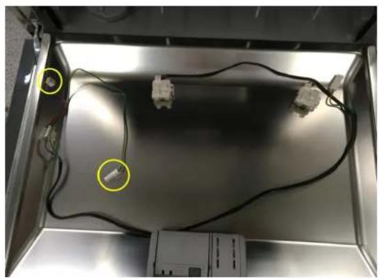
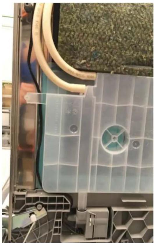
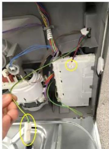
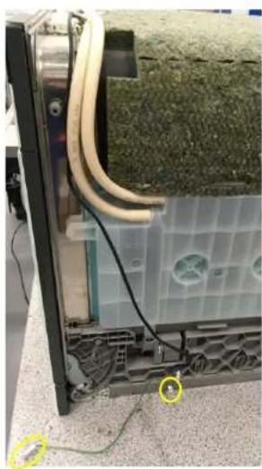
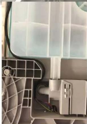
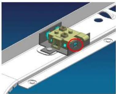
Disconnect the connector from the power module and the metal base's earthing (marked yellow).

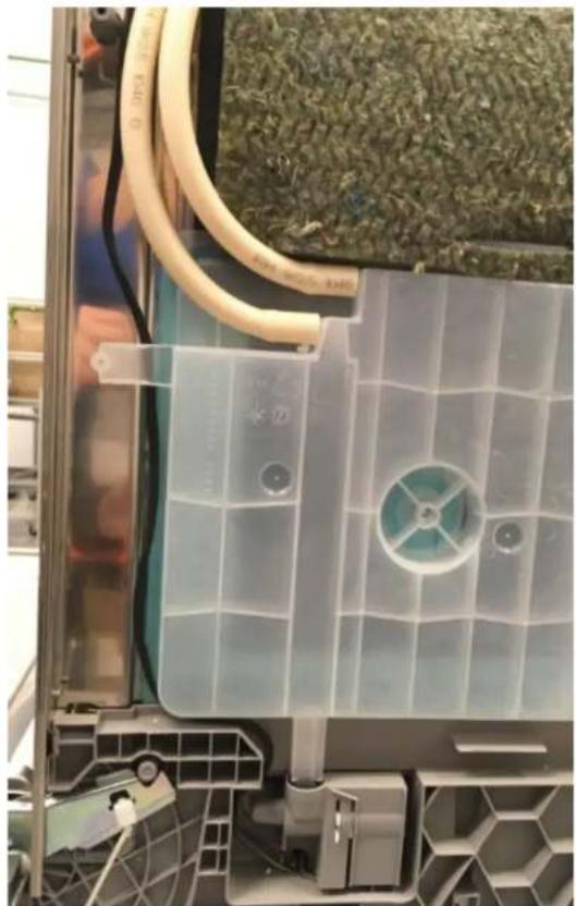
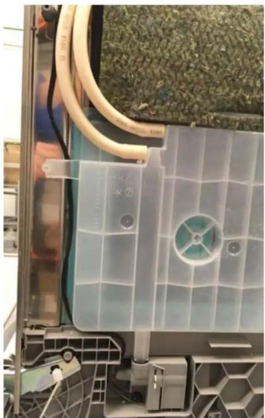
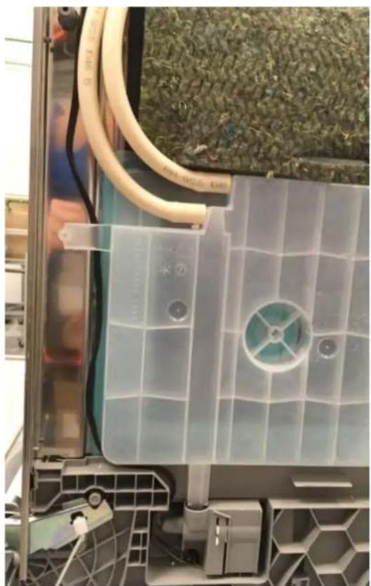
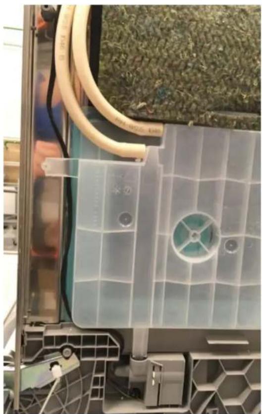
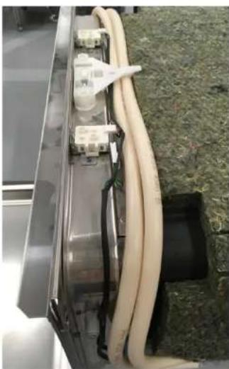
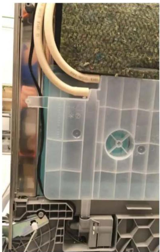
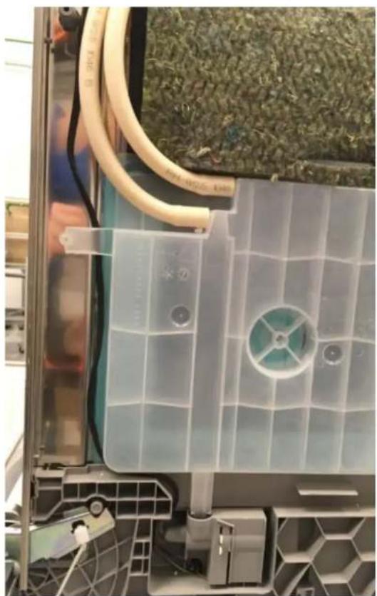
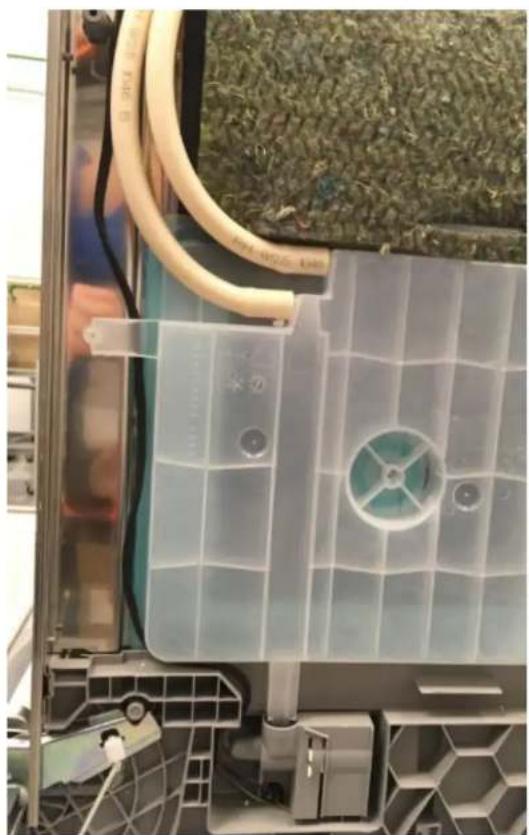
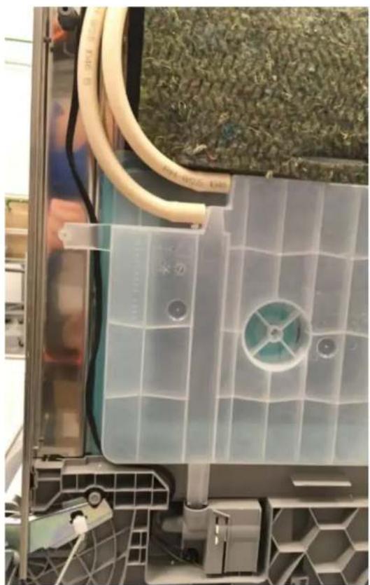
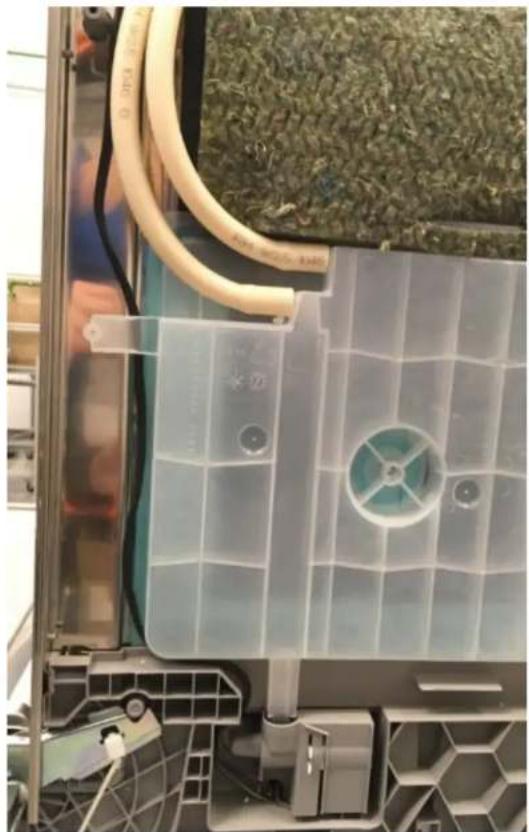
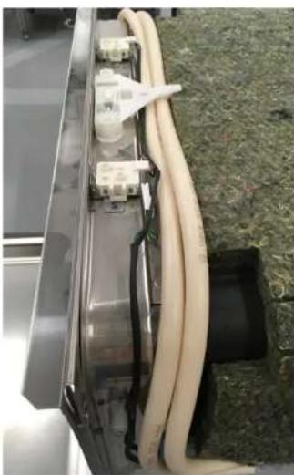
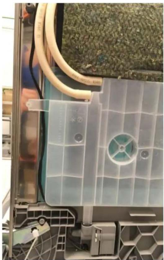
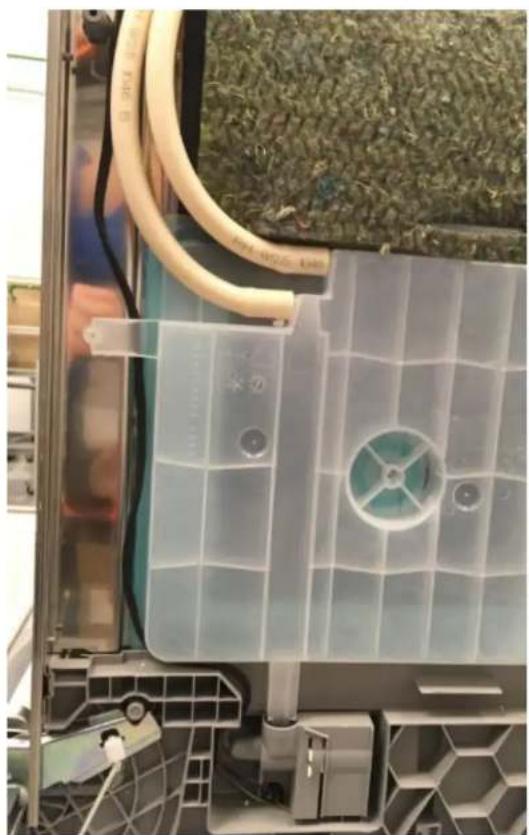
Pull both connectors out through the bottom right side.

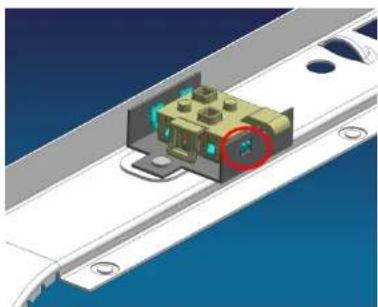
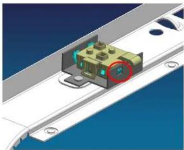
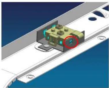
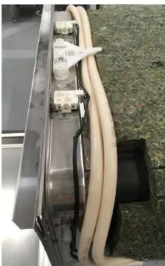
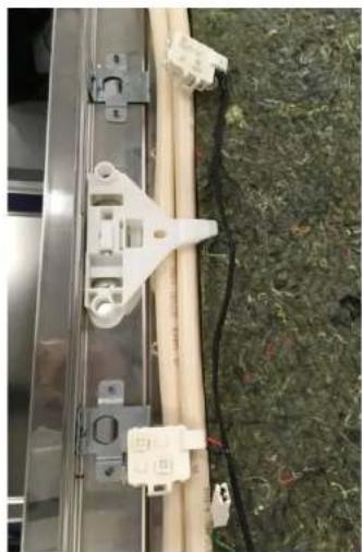
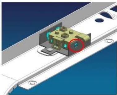
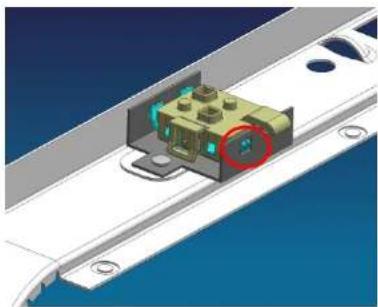
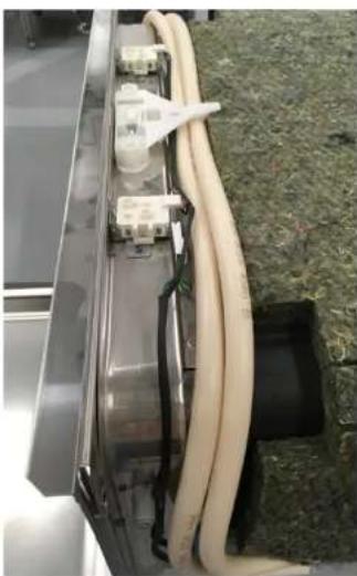
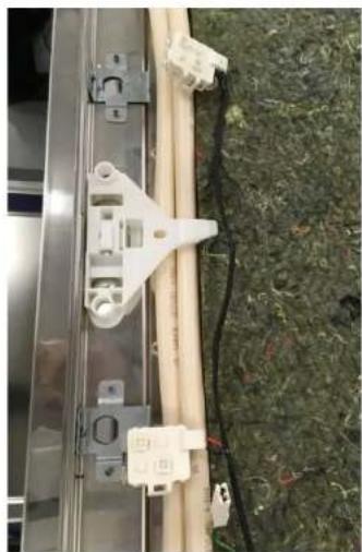
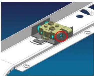
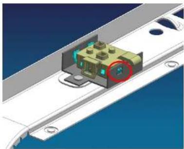
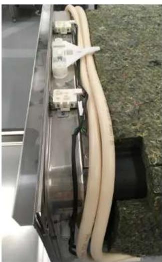
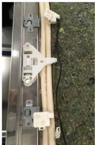
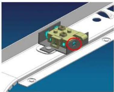
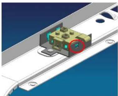
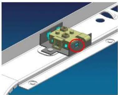
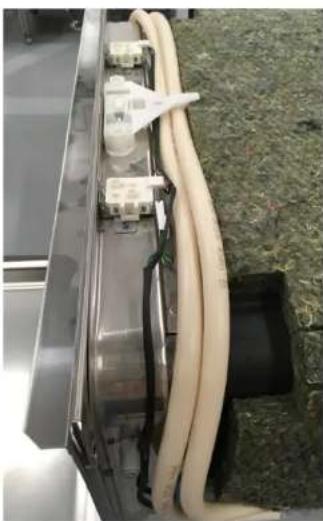
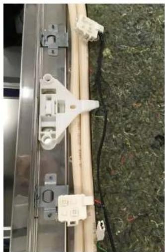
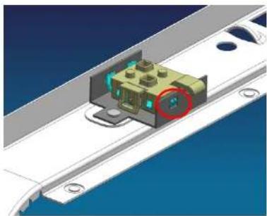
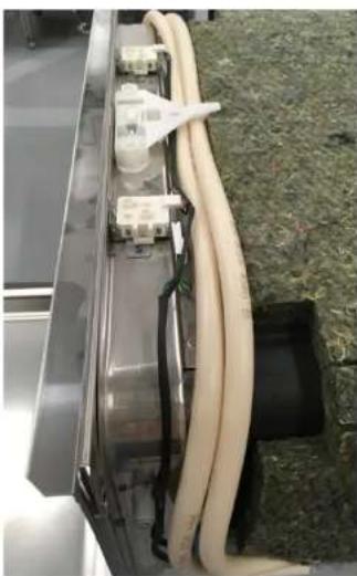
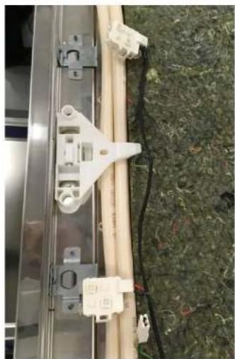
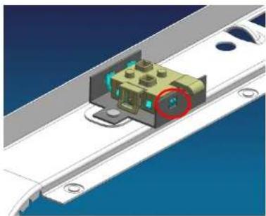
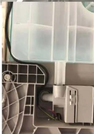
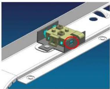
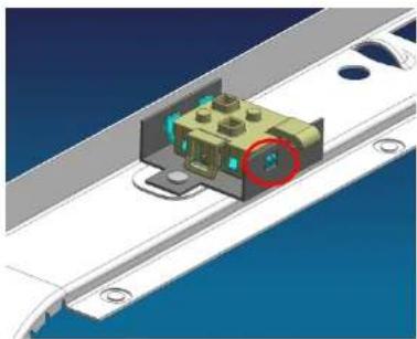
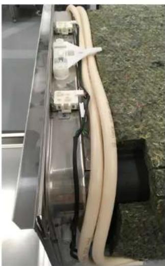
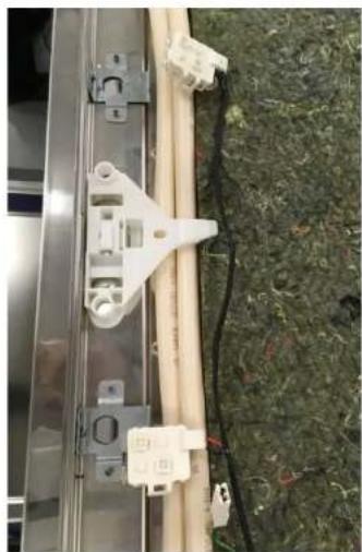
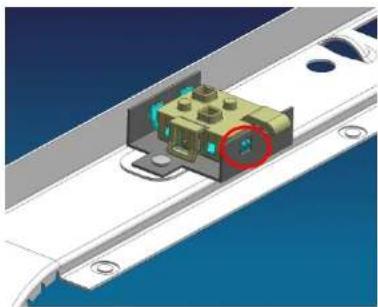
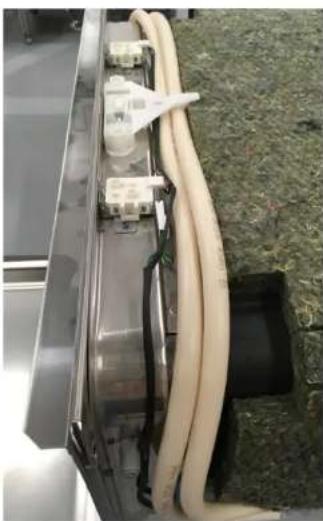
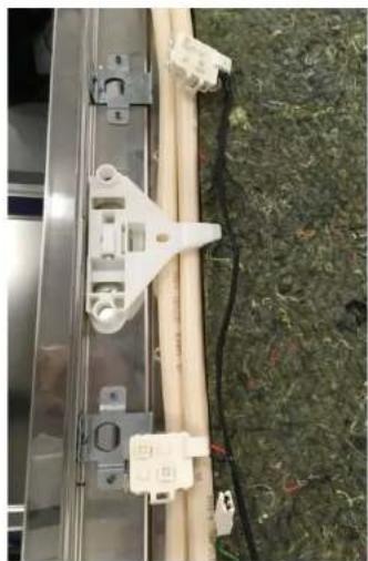
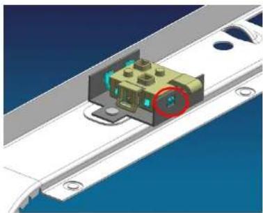
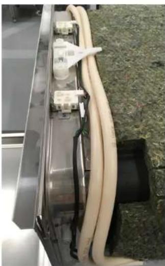
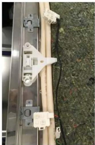
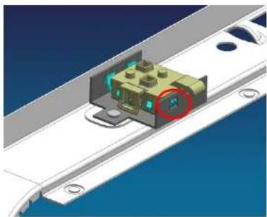
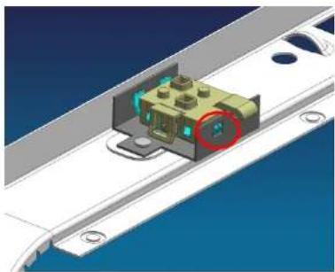
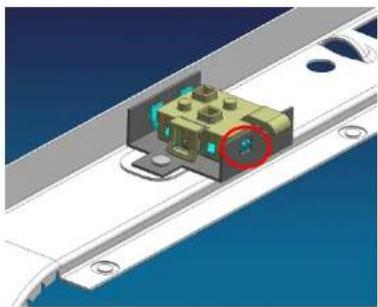
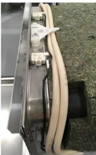
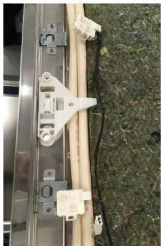
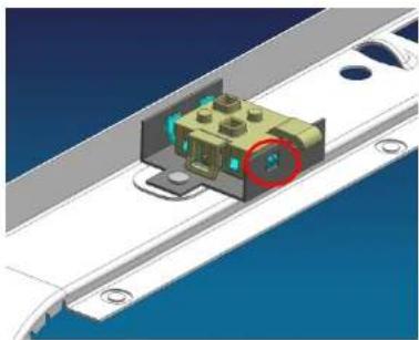
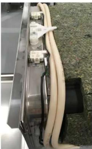
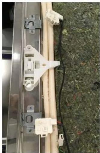
Release the rear latch of the light holder (see image).

Pull all of the lights upwards to remove them.

Remove the set of lights and cable harness.

Interior view of a kitchen appliance showing wiring and components.

Interior view of an open appliance showing wiring and components.

Close-up of a mechanical component with visible wiring and fan assembly.

Close-up of a mechanical component with visible wiring and green material.

Close-up of a mechanical device with beige hoses and connectors, placed on grass.

Close-up of a mechanical assembly with white plastic components and a beige pipe, resting on green textured ground.

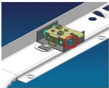
3D mechanical assembly diagram showing a component mounted on a rail with mounting holes.

Interior view of a stainless steel enclosure with visible wiring and two yellow-circled points of a cable.

4.14.2 Install the emotion light

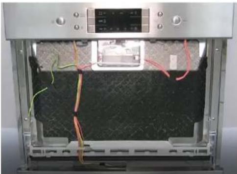
Follow the above steps in reverse order, ensuring that the cable routing is correct.

Interior view of a compact air conditioner unit with visible cooling fans and ventilation duct.

Interior view of a cleanroom or industrial space with plastic partitions and ventilation ducts.

4.1.2 Installing the sprayer

Install the lower sprayer. It clicks into place. Install the upper sprayer and turn it tightly into place.

4.2 Replacing the filters

4.2.1 Removing the filters

Pull the microfilter down.

Mechanical assembly diagram showing a bolted component inserted into a housing with a downward arrow indicating force.

4.2.2 Installing the filter

4.4.2 Disassembly

Technical diagram showing a mechanical assembly with labeled components and directional arrows indicating motion or flow.

Interior view of a stainless steel kitchen appliance with a hand adjusting the door.

Person using a digital kitchen machine with control panel and paper strip.

Interior view of a stainless steel appliance with red wiring and a digital display.

Two-panel image showing a device interior with wiring and a close-up of hands installing or maintaining components (no visible text or symbols)

Interior view of a 3D printer oven with visible wiring and control panel (no text or symbols)

SIEMENS SC05IB00TE - Disassembly - 7

Panel screws

4.7.2 Install the control panel.

4.8.3 Installing the detergent drawer cover

Remove it from the lower mounting position.

Close-up of a mechanical component with red circles highlighting specific parts (no visible text or symbols)

4.9.2 Assembly

Close-up of a white plastic mechanical component with a red X symbol overlay (no text or symbols on the main subject)

Technical diagram showing mechanical assembly steps with magnified views highlighting structural changes.

Diagram showing three different corner joint configurations with checkmark indicators and red X marks indicating failure or rejection.

Technical diagram showing two views of a pipe bend with checkmark and cross symbols indicating inspection or failure.

Close-up of a metallic door with visible clamps and a white plastic clip (no text or symbols).

Close-up of a mechanical component with a star-shaped emblem and number 20, no readable text or symbols beyond the badge.

Close-up of a mechanical component with a gear and a star-shaped badge labeled '20' (no readable text or symbols beyond the badge).

Close-up of a stainless steel kitchen appliance with a hand cleaning the lid (no visible text or symbols).

Close-up of a metallic electronic device with a hand adjusting its top panel (no visible text or symbols).

Close-up of a mechanical device showing internal components with a green cable and a red circle highlighting a small green component (no text or symbols visible).

Close-up of an air conditioner unit showing internal components and wiring (no text or symbols visible).

4.11.2 Assembly

4.12.2 Assembly

1 Cable pulley 2 Cable 4 Tension spring 3 Plastic holder

Close-up of a mechanical component with a red circle highlighting a small connector. No visible text or symbols.

Close-up of a gloved hand adjusting a 3D printer's cable and plastic component. No visible text or symbols.

4.13.2 Installing the hinge

SIEMENS SC05IB00TE - Installing the hinge - 1

SIEMENS SC05IB00TE - Installing the hinge - 2

DANGER

Close-up of a gloved hand inserting wires into a black textured device component. No visible text or symbols.

4.14 Replacing the Emotion light

Interior view of a kitchen appliance showing wiring and components. No visible text or symbols.

Interior view of an open appliance showing wiring and components. No visible text or symbols.

Interior view of a compact air conditioner unit showing internal components like fan, vent, and cooling unit. No text or symbols visible.

Close-up of a mechanical component with visible wiring and green material. No text or symbols present.

Close-up of a mechanical device with beige hoses and connectors, placed on grass. No visible text or symbols.

Close-up of a mechanical assembly with white plastic components and a beige pipe, resting on green textured ground. No visible text or symbols.

3D mechanical assembly diagram showing a component mounted on a rail with mounting holes. No text or symbols visible.

Interior view of a stainless steel enclosure with visible wiring and two yellow-circled points of a cable. No text or symbols.

4.14.2 Installing the Emotion light

Interior view of a cleanroom or industrial space with plastic partitions and ventilation ducts.

REPAIR MANUAL

GV550 BI60-BI45

1 INTRODUCTION......

4 REPAIR......

4.1 Replace the spray arms......

4.2.2 Install the filters

Technical diagram showing a mechanical assembly with labeled components and directional arrows indicating motion or flow.

Interior view of a stainless steel kitchen appliance with a hand adjusting the door.

Person using a digital kitchen machine with control panel and paper strip (no visible text or symbols)

Interior view of a stainless steel appliance with red wiring and a digital display (no visible text or symbols)

Two-panel image showing a device interior with wiring and a close-up of hands installing or maintaining components (no visible text or symbols)

Interior view of a 3D printer oven with visible wiring and control panel (no text or symbols)

SIEMENS SC05IB00TE - Install the filters - 7

Panel screws

Interior view of a stainless steel kitchen appliance showing internal wiring and a control panel (no visible text or symbols)

4.9.2 Assembly

Technical diagram illustrating door panel installation steps with magnified views and red annotations indicating repair or damage points.

Diagram showing three steps of a vehicle door with checkmark and red X marks indicating failure or rejection conditions.

Interior view of a refrigerator with visible door, wheels, and ventilation slots.

Close-up of a mechanical component with a star-shaped emblem and number 20.

Close-up of a mechanical component with a screwdriver and a star-shaped badge labeled '20'.

Close-up of a stainless steel kitchen appliance with a hand cleaning the lid.

Close-up of a silver computer drive casing with a hand adjusting its top panel.

Close-up of a mechanical device showing wiring and a green cable, with a red circle highlighting a small component.

Interior view of a refrigerator showing internal components and wiring.

4.11.2 Assembly

4.12.2 Assembly

1 Rope pulley 2 Rope 4 Tension spring 3 Plastic holder

4.13 Replace the hinge

Prerequisites:

Close-up of a mechanical component with a red circle highlighting a small connector (no visible text or symbols)

Close-up of a gloved hand adjusting a 3D printer's cable and plastic component (no visible text or symbols)

4.13.2 Install the hinge

SIEMENS SC05IB00TE - Install the hinge - 1

SIEMENS SC05IB00TE - Install the hinge - 2

DANGER

Close-up of a gloved hand inserting wires into a black textured device component (no visible text or symbols)

4.14 Replace the interior light

Interior view of a kitchen appliance showing wiring and components (no visible text or symbols)

Interior view of an open appliance showing wiring and components (no visible text or symbols)

Interior view of a compact air conditioner unit showing internal components like fan, vent, and cooling unit (no text or symbols visible)

Close-up of a mechanical component with visible wiring and green material, no text or symbols present

Close-up of a mechanical device with beige hoses and connectors, placed on grass (no visible text or symbols)

Close-up of a mechanical assembly with white components and a beige rod, mounted on a metal frame against a textured green background (no visible text or symbols)

3D mechanical assembly diagram showing a component mounted on a rail with mounting holes (no text or symbols visible)

Interior view of a stainless steel enclosure with black cables and connectors, no visible text or symbols

4.14.2 Install the Emotion Light

Interior view of a cleanroom or industrial space with plastic partitions and ventilation ducts (no visible text or symbols)

1 INTRODUCTION ....

4 REPAIR ....

Technical diagram showing a mechanical assembly with labeled components and directional arrows indicating motion or flow.

Interior view of a stainless steel kitchen appliance with a hand adjusting the door, no visible text or symbols.

Person using a digital kitchen machine with control panel and paper strip, no visible text or symbols.

Interior view of a stainless steel appliance with visible wiring and control panel, no text or symbols.

Two-panel image showing a device interior with wiring and a close-up of hands installing or maintaining components (no visible text or symbols).

Interior view of a 3D printer oven with visible wiring and control panel (no text or symbols).

SIEMENS SC05IB00TE - REPAIR .... - 7

Panel screws

Interior view of a stainless steel kitchen appliance showing internal wiring and control panel (no visible text or symbols).

4.9.2 Assembly

Close-up of a white plastic electronic component with a red X symbol, no visible text or symbols on the main structure.

Technical diagram showing mechanical assembly steps with magnified views highlighting structural changes.

Diagram showing three different corner joint configurations with checkmark indicators and red X marks indicating failure or rejection status.

Interior view of a computer monitor case with visible internal components and a small icon on top (no text or symbols).

Close-up of a mechanical component with a star-shaped badge labeled '20' (no readable text or symbols beyond the badge).

Close-up of a mechanical component with a star-shaped icon labeled '20' (no readable text or symbols beyond the number).

Close-up of a Siemens air conditioner unit with a cloth partially visible, no text or symbols on the device itself.

Close-up of a silver computer drive casing with a hand adjusting its top panel (no visible text or symbols).

Close-up of a mechanical device showing internal components with a green cable and a red circle highlighting a small green component (no text or symbols visible).

Close-up of an air conditioner unit showing internal components and wiring (no text or symbols visible).

4.11.2 Assembly

4.12.2 Assembly

Close-up of a mechanical component with a red circle highlighting a small connector (no visible text or symbols)

Close-up of a gloved hand adjusting a wire cable inside a 3D printer or scanner (no visible text or symbols)

Close-up of a gloved hand holding a wire with multicolored wires, next to a textured black mesh panel (no visible text or symbols)

4.14 Replace the Emotion Light

Interior view of a kitchen appliance showing wiring and components (no visible text or symbols)

Interior view of an open refrigerator showing wiring and components (no visible text or symbols)

Close-up of an air conditioner fan assembly with visible wiring and cooling unit (no text or symbols)

Close-up of a mechanical component with visible wiring and green material, no text or symbols present

Close-up of a mechanical device with beige hoses and connectors, placed on grass (no visible text or symbols)

Close-up of a mechanical assembly with white components and a beige rod, mounted on a metal frame against a textured green background (no visible text or symbols)

3D mechanical assembly diagram showing a component mounted on a rail with mounting holes (no text or symbols visible)

Interior view of a stainless steel enclosure with visible wiring and two yellow-circled points of a cable (no text or symbols)

4.14.2 Install the Emotion Light

Interior view of a cleanroom or industrial space with plastic partitions and ventilation ducts (no visible text or symbols)

REPAIR INSTRUCTIONS

GV550 BI60-BI45

1 INTRODUCTION ....

4 REPAIR......

Technical diagram showing a mechanical assembly with labeled components and directional arrows indicating motion or flow.

Interior view of a stainless steel kitchen appliance with a hand adjusting the door panel, no visible text or symbols.

Close-up of hands operating a stainless steel appliance with control panel and battery, no visible text or symbols.

Two-panel photo showing hands installing wiring on a device inside a refrigerator, no visible text or symbols.

Close-up of gloved hands installing or adjusting a mechanical component with green wires. No visible text or symbols.

Interior view of an open industrial oven with visible wiring and control panel. No text or symbols.

SIEMENS SC05IB00TE - REPAIR INSTRUCTIONS - 7

Aperture screws

Interior view of a stainless steel kitchen appliance showing internal wiring and a control panel. No visible text or symbols.

4.9.2 Assembly

Close-up of a white plastic mechanical component with a red X symbol overlay. No text or symbols on the main subject.

Technical diagram showing mechanical assembly steps with magnified views highlighting structural changes.

Diagram showing three different corner joint configurations with checkmark indicators and red X marks indicating failure or error.

Interior view of a computer drive bay with visible mechanical components and mounting bracket (no text or symbols).

Close-up of a mechanical component with a star-shaped emblem and number 20, no readable text or symbols present.

Close-up of a mechanical component with a star-shaped icon labeled '20' (no readable text or symbols beyond the number).

Close-up of a Siemens air conditioner unit with a cloth partially visible, no text or symbols on the device itself.

Close-up of a silver computer drive casing with a hand adjusting its top panel (no visible text or symbols).

Close-up of a mechanical device showing internal components with a green cable and a red circle highlighting a small green component (no text or symbols visible).

Close-up of an air conditioner unit showing internal components and wiring (no text or symbols visible).

4.11.2 Assembly

4.12.2 Assembly

Close-up of a mechanical component with a red circle highlighting a small connector.

Close-up of a gloved hand adjusting a 3D printer's cable and plastic component.

Close-up of a robotic arm holding a wire with multicolored wires, partially enclosed in a mechanical component.

Interior view of an open refrigerator showing wiring and components.

Close-up of an air conditioner fan assembly with visible wiring and cooling unit.

Close-up of a mechanical device showing internal components and wiring.

Close-up of a metallic industrial device with beige hoses and connectors, placed on grass.

3D mechanical assembly diagram showing a component inserted into a bracket with mounting holes.

Close-up of a metallic mechanical bracket with attached white connectors and wires, placed on grass.

Interior view of a stainless steel enclosure with visible wiring and connectors.

Interior view of an air conditioner unit showing internal compartments and wiring.

4 REPAIR......

Technical diagram showing a mechanical assembly with labeled components and directional arrows indicating motion or flow.

Interior view of a stainless steel kitchen appliance with a hand adjusting the door.

Close-up of a gloved hand pressing a white plastic component on a stainless steel appliance.

Two-panel photo showing hands installing wiring on a device inside a refrigerator.

Close-up of gloved hands installing or adjusting a metal component with a green cable (no visible text or symbols)

Interior view of an open industrial oven with visible wiring and control panel (no text or symbols)

SIEMENS SC05IB00TE - Assembly - 18

Panel screws

4.9.2 Assembly
Close-up of a white plastic electronic component with a red X symbol, no visible text or symbols on the main structure.

Technical diagram showing mechanical assembly steps with magnified views highlighting structural changes.

Diagram showing three stages of a vehicle door with checkmark and red X marks indicating success or failure.

Interior view of a computer drive bay with visible internal components and mounting bracket, no text or symbols.

Close-up of a mechanical component with a star-shaped emblem and number 20, no readable text or symbols beyond the badge.

Close-up of a mechanical component with a tool and circular inset showing a star symbol labeled '20', no readable text or symbols beyond the number.

Close-up of a Siemens air conditioner unit with a cloth partially visible, no text or symbols on the device itself.

Close-up of a metallic electronic device with a hand adjusting its top panel, no visible text or symbols.

Close-up of a mechanical device showing internal components with a green cable and a red circle highlighting a small green component, no text or symbols visible.

Close-up of an air conditioner unit showing internal components and wiring, no text or symbols visible.

1 Pulley

2 Rope

3 Plastic base

4 Tension spring

Close-up of a mechanical component with a red circle highlighting a small connector. No visible text or symbols.

Close-up of a robotic arm holding a wire with multicolored wires, next to a black textured fabric or mesh material. No visible text or symbols.

Close-up of a robotic arm holding a wire with multicolored wires, partially enclosed in a mechanical component. No visible text or symbols.

Interior view of an open refrigerator showing wiring and components. No visible text or symbols.

Close-up of an air conditioner fan assembly with visible wiring and cooling unit. No text or symbols.

Close-up of a mechanical component with visible wiring and green material. No text or symbols present.

Close-up of a mechanical device with beige hoses and connectors, placed on grass. No visible text or symbols.

Close-up of a mechanical assembly with white components and a beige rod, mounted on a metal frame against a textured green background. No visible text or symbols.

3D mechanical assembly diagram showing a component mounted on a rail with mounting holes. No text or symbols visible.

Interior view of a stainless steel enclosure with visible wiring and two yellow-circled points of interest. No text or symbols.

Interior view of a cleanroom or industrial space with plastic partitions and ventilation ducts. No visible text or symbols.

REPAIR MANUAL

GV550 BI60-BI45

  1. INTRODUCTION......
  1. REPAIR ......

Technical diagram showing a mechanical assembly with labeled components and directional arrows indicating motion or flow.

Interior view of a stainless steel kitchen appliance with a hand adjusting the door (no visible text or symbols).

Person cleaning a stainless steel appliance with red annotations highlighting components (no visible text or symbols).

Interior view of a stainless steel appliance with visible circuit board and wiring, no text or symbols present.

Two-panel image showing a device interior with wiring and a close-up of hands installing or maintaining components (no visible text or symbols)

Interior view of a 3D printer oven with visible wiring and control panel (no text or symbols)

SIEMENS SC05IB00TE - REPAIR MANUAL - 7

Panel screws

4.9.2 Assembly
3D-printed mechanical component with visible structural ribs and mounting brackets, no text or symbols present

Technical diagram showing mechanical assembly steps with magnified views highlighting structural changes.

Diagram showing three stages of a vehicle door with checkmark and red X marks indicating success or failure.

Interior view of a refrigerator with visible door, wheels, and ventilation slots (no text or symbols).

Close-up of a mechanical component with a star-shaped emblem and number 20, no readable text or symbols present.

Close-up of a mechanical component with a gear and a star-shaped icon labeled '20' (no readable text or symbols beyond the number).

Close-up of a stainless steel kitchen appliance with a hand cleaning the lid (no visible text or symbols).

Close-up of a metallic electronic device with a hand adjusting its top panel (no visible text or symbols).

Close-up of a mechanical device showing internal components with a green cable and a red circle highlighting a small green component (no text or symbols visible).

Close-up of an air conditioner unit showing internal components and wiring (no text or symbols visible).

Close-up of a mechanical component with a red circle highlighting a small connector (no visible text or symbols)

Close-up of a gloved hand adjusting a 3D printer's cable and plastic component (no visible text or symbols)

Close-up of a gloved hand inserting wires into a black textured material component (no visible text or symbols)

4.14 Emotion Light replacement

Interior view of a kitchen appliance showing wiring and components (no visible text or symbols)

Interior view of an open appliance showing wiring and components (no visible text or symbols)

Close-up of a mechanical component with visible wiring and fan assembly (no text or symbols)

Close-up of a mechanical component with visible wiring and green material, no text or symbols present

Close-up of a mechanical device with beige hoses and connectors, placed on grass (no visible text or symbols)

Close-up of a mechanical assembly with attached components and wires on a textured surface (no visible text or symbols)

3D mechanical assembly diagram showing a component mounted on a rail with mounting holes (no text or symbols visible)

Interior view of a stainless steel enclosure with black cables and connectors, no visible text or symbols

Interior view of a cleanroom or industrial space with plastic partitions and ventilation ducts (no visible text or symbols)

4 REPAIR ....

Technical diagram showing a mechanical assembly with labeled components and directional arrows indicating motion or flow.

Interior view of a stainless steel kitchen appliance with a hand adjusting the door (no visible text or symbols).

Person using a digital kitchen machine with control panel and paper strip (no visible text or symbols).

Interior view of a stainless steel appliance with red wiring and a digital display (no visible text or symbols).

Two-panel image showing a device interior with wiring and a close-up of hands installing or maintaining components (no visible text or symbols)

Interior view of a 3D printer oven with visible wiring and control panel (no text or symbols)

SIEMENS SC05IB00TE - REPAIR .... - 7

Panel screws

Interior view of a stainless steel appliance with visible wiring and control panel (no text or symbols)

4.9.2 Assembly

3D-printed mechanical component with a red X symbol overlay (no text or symbols on the part itself)

Technical diagram showing mechanical assembly steps with magnified views highlighting structural changes.

Diagram showing three stages of a vehicle door with checkmark and red X marks indicating failure or rejection status.

Interior view of a refrigerator with visible door, wheels, and ventilation slots (no text or symbols).

Close-up of a mechanical component with a star-shaped emblem and number 20, no readable text or symbols beyond the badge.

Close-up of a mechanical component with a gear and a star-shaped badge labeled '20' (no readable text or symbols beyond the badge).

Close-up of a stainless steel kitchen appliance with a hand cleaning the lid (no visible text or symbols).

Close-up of a silver computer drive chassis with a hand adjusting its top panel (no visible text or symbols).

Close-up of a mechanical device showing internal components with a green cable and a red circle highlighting a small green component (no text or symbols visible).

Close-up of an air conditioner unit showing internal components and wiring (no text or symbols visible).

4.11.2 Assembly

4.12.2 Assembly

Close-up of a mechanical component with a red circle highlighting a small connector (no visible text or symbols)

Close-up of a gloved hand adjusting a 3D printer's cable and plastic component (no visible text or symbols)

Close-up of a robotic arm holding a wire with multicolored wires, partially enclosed in a mechanical component (no visible text or symbols)

Interior view of an open appliance showing wiring and components (no visible text or symbols)

Interior view of a compact air conditioner unit showing internal components like fan, vent, and cooling unit (no text or symbols visible)

Close-up of a mechanical component with visible wiring and green material, no text or symbols present

Close-up of a mechanical device with beige hoses and connectors, placed on grass (no visible text or symbols)

Close-up of a mechanical assembly with white components and a beige rod, mounted on a metal frame against a textured green background (no visible text or symbols)

3D mechanical assembly diagram showing a component mounted on a rail with mounting holes (no text or symbols visible)

Interior view of a stainless steel enclosure with black cables and connectors, no visible text or symbols

Interior view of a cleanroom or industrial space with plastic partitions and ventilation ducts (no visible text or symbols)

REASSEMBLY

GV550 BI60-BI45

  1. INTRODUCTION......

1.1. Purpose of the document......

  1. REPAIR......

Pull out the fine filter.

Mechanical assembly diagram showing a bolted component inserted into a housing with a downward arrow indicating force (no text or symbols present).

Press the retaining clips (1) and pull the coarse filter upwards (2).

Technical diagram showing mechanical assembly steps with numbered instructions and directional arrows.

Technical diagram showing a mechanical assembly with labeled components and directional arrows indicating motion or flow.

Interior view of a stainless steel kitchen appliance with a hand adjusting the door (no visible text or symbols).

Person using a digital kitchen machine with control panel and paper strip (no visible text or symbols).

Interior view of a stainless steel appliance with visible circuit board and wiring, no text or symbols present.

Two-panel image showing a device interior with wiring and a close-up of hands installing or maintaining components (no visible text or symbols)

Interior view of a 3D printer oven with visible wiring and control panel (no text or symbols)

SIEMENS SC05IB00TE - REASSEMBLY - 9

Panel screws

Interior view of a stainless steel kitchen appliance showing internal wiring and a control panel (no visible text or symbols)

Pull it out of the base, pulling upwards.

Close-up of a gloved hand installing or adjusting a white plastic component on a mechanical device (no visible text or symbols)

4.9.2 Installation

Secure the white trim to the base.

Close-up of a gloved hand assembling a white plastic mechanical component inside a device casing (no visible text or symbols)

3D-printed mechanical component with visible structural ribs and mounting brackets, no text or symbols present

Technical diagram showing mechanical assembly steps with magnified views highlighting structural changes.

Diagram showing three stages of a vehicle door with checkmark and red X marks indicating failure or rejection status.

Interior view of a computer drive bay with visible internal components and a small component on top (no text or symbols).

Close-up of a mechanical component with a star-shaped badge labeled '20' (no readable text or symbols beyond the badge).

Close-up of a mechanical component with a star-shaped icon labeled '20' (no readable text or symbols beyond the number).

Close-up of a Siemens air conditioner unit with a cloth partially visible, no text or symbols on the device itself.

Close-up of a silver computer drive chassis with a hand adjusting its top panel (no visible text or symbols).

Close-up of a mechanical device showing internal components with a green cable and a red circle highlighting a small green component (no text or symbols visible).

Close-up of an air conditioner unit showing internal components and wiring (no text or symbols visible).

4.11.2 Installation

4.12.2 Installation

Close-up of a mechanical component with a red circle highlighting a small connector.

Close-up of a gloved hand adjusting a 3D printer's cable and plastic component.

Close-up of a gloved hand inserting wires into a black textured device.

4.14 Replacing the Emotion Light

Interior view of a kitchen appliance showing wiring and components.

Interior view of an open appliance showing wiring and components.

Close-up of a mechanical component with visible wiring and fan assembly.

Close-up of a mechanical component with visible wiring and green material.

Close-up of a mechanical device with beige hoses and connectors, placed on grass.

Close-up of a mechanical assembly with white components and a beige rod, mounted on a metal frame against a textured green background.

3D mechanical assembly diagram showing a component mounted on a rail track.

Interior view of a stainless steel enclosure with visible wiring and two yellow-circled points of interest.

Interior view of a cleanroom or industrial space with plastic partitions and ventilation ducts.

REPAIR INSTRUCTIONS

GV550 BI60-BI45

4 REPAIR......

4.3 Replacing the drain pump cover

Lift the pump cover upwards.

Mechanical assembly diagram showing a blue clamp bracket inserted into a component (no text or symbols visible).

Technical diagram showing a mechanical assembly with labeled components and directional arrows indicating motion or flow.

4.5.2 Additional support for small items

Interior view of a stainless steel kitchen appliance with a hand adjusting the door (no visible text or symbols).

Person operating a refrigerator with digital display and red annotations (no readable text or symbols).

Interior view of a stainless steel appliance with visible wiring and control panel (no text or symbols).

Two-panel image showing a device interior with wiring and a close-up of hands installing or maintaining components (no visible text or symbols)

Interior view of a 3D printer oven with visible wiring and control panel (no text or symbols)

SIEMENS SC05IB00TE - Additional support for small items - 6

Panel screws

Interior view of a stainless steel oven with visible wiring and control panel (no text or symbols)

4.9.2 Assembly

Close-up of a white plastic mechanical component with a red X symbol overlay (no text or symbols on the main structure)

Technical diagram showing mechanical assembly steps with magnified views highlighting structural changes and red arrows indicating motion direction.

Diagram showing three steps of a vehicle door with checkmark and red X marks indicating failure or rejection conditions.

Interior view of a computer drive bay with visible internal components and mounting bracket. No text or symbols.

Close-up of a mechanical component with a star-shaped emblem and the number 20. No readable text or symbols present.

Close-up of a mechanical component with a tool and circular inset showing a star symbol labeled '20'. No readable text or symbols beyond the number.

Close-up of a Siemens air conditioner unit with a cloth partially visible. No text or symbols on the device itself.

Close-up of a silver computer drive chassis with a hand adjusting its top panel. No visible text or symbols.

Close-up of a mechanical device showing internal components with a green cable and a red circle highlighting a small green component. No text or symbols visible.

Close-up of an air conditioner unit showing internal components and wiring. No text or symbols visible.

4.11.2 Assembly

4.12.2 Assembly

1 Screw 2 Rope 3 Plastic holder 4 Tension spring

4.13 Replacing the hinge

Close-up of a mechanical component with a red circle highlighting a small connector (no visible text or symbols)

Close-up of a gloved hand adjusting a 3D printer's cable and plastic component (no visible text or symbols)

Close-up of a gloved hand inserting wires into a black textured device component (no visible text or symbols)

4.14 Replacing the interior lighting module

Interior view of a kitchen appliance showing wiring and components (no visible text or symbols)

Close-up of an open refrigerator interior showing wiring and components, with a hand adjusting the cable (no visible text or symbols)

Interior view of a compact air conditioner unit showing internal components like fan, vent, and cooling unit (no text or symbols visible)

Close-up of a mechanical component with visible wiring and green material, no text or symbols present

Close-up of a mechanical device with beige hoses and connectors, placed on grass (no visible text or symbols)

Close-up of a mechanical assembly with white components and a beige rod, mounted on a metal frame against a textured green background (no visible text or symbols)

3D mechanical assembly diagram showing a component mounted on a rail track (no visible text or symbols)

Interior view of a stainless steel enclosure with black cables and connectors, no visible text or symbols

4.14.2 Installing the interior lighting module

Interior view of a cleanroom or industrial space with plastic partitions and ventilation ducts (no visible text or symbols)

REPAIR MANUAL

GV550 BI60-BI45

1 INTRODUCTION......

4 REPAIR......

4.1 Replacing the spray arm ....

4.2 Replacing the filters....

4.3 Replacing the cover on the drain pump......

4.4 Replacing the plug....

4.5 Basket systems....

Push the lower spray arm up.

Diagram of a kitchen appliance with a blue handle and a black upward arrow indicating motion (no text or symbols).

4.1.2 Installing the spray arm

Pull the micro filter down.

Mechanical assembly diagram showing a bolted component inserted into a housing with a downward arrow indicating force (no text or symbols present).

Press the locking buttons (1) and pull up the coarse filter (2).

Technical diagram showing a two-step assembly process with labeled steps and directional arrows indicating motion or movement.

4.2.2 Installing the filters

  1. Reinstall the filter system.

Make sure the locking tabs on the coarse filter snap into place.

  1. Insert the filter system into the appliance and turn the coarse filter clockwise.

Make sure the arrow markings align.

Close-up of a white plastic container with a mesh grille and a small triangular object on the side (no visible text or symbols).

4.3 Replacing the drain pump cover

Prerequisites:

Pull the pump cover up.

Diagram of a mechanical component with a blue clamp and a black arrow indicating force or direction (no text or symbols).

Technical diagram showing a mechanical assembly with labeled components and directional arrows indicating motion or flow.

4.5.2 Extra support for small parts

Interior view of a stainless steel kitchen appliance with a hand adjusting the door (no visible text or symbols).

Person using a digital kitchen machine with control panel and paper strip (no visible text or symbols).

Interior view of a stainless steel appliance with red wiring and a digital display (no visible text or symbols).

Two-panel image showing a device interior with wiring and a close-up of hands installing or maintaining components (no visible text or symbols)

Interior view of a 3D printer oven with visible wiring and control panel (no text or symbols)

SIEMENS SC05IB00TE - Extra support for small parts - 6

Panel screws

Interior view of a stainless steel appliance with visible wiring and control panel (no text or symbols)

Place the wiring harness correctly in the lower gasket bracket.

4.7 Replacing the control panel

Prerequisites:

4.7.2 Mounting the control panel.

4.9.2 Mounting

Check that the gasket is flush with the lower base.

Technical diagram showing pipe connection and safety symbols with crosshair indicators

Technical diagram showing mechanical assembly steps with magnified views highlighting structural changes and red arrows indicating motion direction.

Diagram showing three different corner joint configurations with checkmark indicators and red X marks indicating failure.

Technical diagram showing two views of a pipe bend with checkmark and cross symbols indicating inspection or failure.

Close-up of a metallic door with visible clamps and a white plastic clip (no text or symbols).

4.11 Replacing the lower cover

Prerequisite

Close-up of a mechanical component with a star-shaped emblem and number 20, no readable text or symbols present.

Close-up of a mechanical component with a gear and a star-shaped icon labeled '20' (no readable text or symbols beyond the number).

Close-up of a stainless steel kitchen appliance with a hand cleaning the lid (no visible text or symbols).

Close-up of a metallic electronic device with a hand adjusting its top panel (no visible text or symbols).

Close-up of a mechanical device showing internal components with a green cable and a red circle highlighting a small green component (no text or symbols visible).

Interior view of an air conditioner unit showing internal components and wiring (no text or symbols visible).

4.11.2 Mounting

4.12.2 Mounting

Close-up of a mechanical component with a red circle highlighting a small connector (no visible text or symbols)

Close-up of a gloved hand adjusting a 3D printer's cable and plastic component (no visible text or symbols)

4.13.2 Mounting the hinge

SIEMENS SC05IB00TE - Mounting the hinge - 1

SIEMENS SC05IB00TE - Mounting the hinge - 2

DANGER

Close-up of a gloved hand inserting wires into a black textured device component (no visible text or symbols)

4.14 Replacing the Emotion Light

Interior view of a kitchen appliance showing wiring and components (no visible text or symbols)

Interior view of an open appliance showing wiring and components (no visible text or symbols)

Close-up of a mechanical component with visible wiring and fan assembly (no text or symbols)

Close-up of a mechanical component with visible wiring and green material, no text or symbols present

Close-up of a mechanical device with beige hoses and connectors, placed on grass (no visible text or symbols)

Close-up of a mechanical assembly with white components and a beige rod, mounted on a metal frame against a textured green background (no visible text or symbols)

3D mechanical assembly diagram showing a component mounted on a rail with mounting holes (no text or symbols visible)

Interior view of an open industrial enclosure with visible wiring and a small component (no text or symbols)

4.14.2 Mounting the Emotion Light

Interior view of a cleanroom or industrial space with plastic partitions and ventilation ducts (no visible text or symbols)

REPAIR INSTRUCTIONS

GV550 BI60-BI45

1 INTRODUCTION ....

1.1 Purpose of the document ....

4 REPAIR......

Technical diagram showing a mechanical assembly with labeled components and directional arrows indicating motion or flow.

Interior view of a stainless steel kitchen appliance with a hand adjusting the door.

Person using a digital kitchen machine with control panel and paper strip.

Interior view of a stainless steel appliance with red wiring and a digital display.

Two-panel image showing a device interior with wiring and a close-up of hands installing or maintaining components (no visible text or symbols)

Interior view of a 3D printer oven with visible wiring and control panel (no text or symbols)

Close-up of a metal cutting machine with red circles highlighting specific features (no text or symbols visible)

Interior view of a stainless steel appliance with visible wiring and control panel (no text or symbols)

4.9.2 Installation

Close-up of a white plastic mechanical component with a red X symbol overlay (no text or symbols on the main structure)

Technical diagram showing mechanical assembly steps with magnified views highlighting structural changes and red arrows indicating motion or force vectors.

Diagram showing three different corner joint configurations with checkmark indicators and red X marks indicating failure or error.

Technical diagram showing two views of a pipe bend with checkmark and cross symbols indicating inspection or failure.

Close-up of a metallic door with visible clamps and a white plastic clip.

Close-up of a mechanical component with a star-shaped emblem and the number 20.

Close-up of a mechanical component with a tool and circular inset showing a star symbol labeled '20'.

Close-up of a Siemens air conditioner unit with a cloth partially visible.

Close-up of a metallic electronic device with a hand adjusting its top panel.

Close-up of a mechanical device showing internal components with a green cable and a red circle highlighting a small green component.

Close-up of an air conditioner unit showing internal components and wiring.

4.11.2 Installation

4.12.2 Installation

Close-up of a mechanical component with a red circle highlighting a small connector. No visible text or symbols.

Close-up of a gloved hand adjusting a 3D printer's cable and plastic component. No visible text or symbols.

Close-up of a gloved hand holding a wire with colored wires, next to a black textured surface. No visible text or symbols.

4.14 Replacing the Emotion Light

Interior view of a kitchen appliance showing wiring and components. No visible text or symbols.

Interior view of an open appliance showing wiring and components. No visible text or symbols.

Close-up of a mechanical component with visible wiring and fan assembly. No text or symbols.

Close-up of a mechanical component with visible wiring and green material. No text or symbols present.

Close-up of a mechanical device with beige hoses and connectors, placed on grass. No visible text or symbols.

Close-up of a mechanical assembly with white components and a beige rod, mounted on a metal frame against a textured green background. No visible text or symbols.

3D mechanical assembly diagram showing a component mounted on a rail with mounting holes. No text or symbols visible.

Interior view of an open industrial enclosure with visible wiring and a small component. No text or symbols.

Interior view of a cleanroom or industrial space with plastic partitions and ventilation ducts (no visible text or symbols)

4 REPAIR ....

4.1.2 Installing the spray arm

4.2.2 Installing the filters

4.3 Replacing the drain pump cover

Prerequisites:

Technical diagram showing a mechanical assembly with labeled components and directional arrows indicating motion or flow.

4.6 Replacing the outer door

Prerequisites:

Interior view of a stainless steel kitchen appliance with a hand adjusting the door (no visible text or symbols)

Person using a digital kitchen appliance with control panel and red annotation arrows (no visible text or symbols)

Interior view of a stainless steel appliance with visible circuit board and wiring, no text or symbols present

Two-panel image showing a device with wiring and a close-up of hands installing or maintaining a component (no visible text or symbols)

Interior view of a 3D printer oven with visible wiring and control panel (no text or symbols)

SIEMENS SC05IB00TE - Prerequisites: - 6

Panel screws

4.6.2 Installing the outer door

Interior view of a stainless steel appliance with visible wiring and control panel (no text or symbols)

4.7.2 Installing the control panel.

4.8.3 Installing the detergent dispenser cover

4.9.2 Assembly

Fit the white bracket onto the base.

Close-up of a gloved hand assembling a white plastic mechanical component inside a device casing (no visible text or symbols)

Close-up of a white plastic mechanical component with a red X symbol overlay (no text or symbols on the main subject)

Technical diagram showing mechanical assembly steps with magnified views highlighting structural changes and red arrows indicating motion direction.

Diagram showing three stages of a vehicle door with checkmark and red X marks indicating failure or rejection status.

SIEMENS SC05IB00TE - Assembly - 5

4.11 Replacing the bottom cover

Prerequisite:

Close-up of a mechanical component with a star-shaped emblem and number 20, no readable text or symbols present.

Close-up of a mechanical component with a tool and circular inset showing a star symbol labeled '20' (no readable text or symbols beyond the number)

Close-up of a Siemens air conditioner unit with a cloth partially visible, no text or symbols on the device itself.

Close-up of a metallic electronic device with a hand adjusting its top panel (no visible text or symbols)

Close-up of a mechanical device showing internal components with a green cable and a red circle highlighting a small green component (no text or symbols visible)

Close-up of an air conditioner unit showing internal components and wiring (no text or symbols visible)

4.11.2 Assembly

4.12.2 Assembly

1 Pulley 2 Rope 4 Tension spring 3 Plastic bracket

4.13 Replacing the hinge

Prerequisites:

Remove the inner and outer doors.

Remove the bottom base.

Close-up of a mechanical component with a red circle highlighting a small connector. No visible text or symbols.

Close-up of a gloved hand adjusting a 3D printer's cable and plastic component. No visible text or symbols.

4.13.2 Installing the hinge

SIEMENS SC05IB00TE - Installing the hinge - 1

SIEMENS SC05IB00TE - Installing the hinge - 2

DANGER

Close-up of a gloved hand inserting wires into a black textured device component. No visible text or symbols.

4.14 Replacing the Emotion Light

Interior view of a kitchen appliance showing wiring and components. No visible text or symbols.

Interior view of an appliance showing wiring and components, with a hand holding a cable. No visible text or symbols.

Close-up of an air conditioner fan assembly with visible wiring and cooling unit. No text or symbols.

Close-up of a mechanical component with visible wiring and green material. No text or symbols present.

Close-up of a mechanical device with beige hoses and connectors, placed on grass. No visible text or symbols.

Close-up of a mechanical assembly with white components and a beige rod, mounted on a metal frame against a textured green background. No visible text or symbols.

3D mechanical assembly diagram showing a component mounted on a rail bar with mounting holes. No text or symbols visible.

Interior view of a stainless steel enclosure with visible wiring and two yellow-circled points of interest. No text or symbols.

4.14.2 Installing the Emotion Light

Interior view of a cleanroom or industrial space with plastic partitions and ventilation ducts (no visible text or symbols).

REPAIR MANUAL

GV550 BI60-BI45

1 INTRODUCTION......

4 REPAIR......

4.2.2 Mounting the filters

Technical diagram showing a mechanical assembly with labeled components and directional arrows indicating motion or flow.

Interior view of a stainless steel kitchen appliance with a hand adjusting the door (no visible text or symbols).

Person using a digital kitchen machine with control panel and paper strip (no visible text or symbols)

Interior view of a stainless steel appliance with red wires and a digital display (no visible text or symbols)

Two-panel image showing a device interior with wiring and a close-up of hands installing or maintaining components (no visible text or symbols)

Interior view of a 3D printer oven with visible wiring and control panel (no text or symbols)

SIEMENS SC05IB00TE - Mounting the filters - 7

Panel screws

4.6.2 Mounting the outer door

Interior view of a stainless steel kitchen appliance showing internal wiring and a control panel (no visible text or symbols)

4.9.2 Assembly

Close-up of a white plastic electronic component with a red X symbol, no visible text or symbols on the main structure.

4.10 Replacing the door gasket

Technical diagram showing mechanical assembly steps with magnified views and red annotations indicating features

Diagram showing three stages of a vehicle door with checkmark and red X marks indicating failure or failure.

Interior view of a computer drive bay with visible internal components and mounting bracket (no text or symbols)

Close-up of a mechanical component with a star-shaped emblem and number 20, no readable text or symbols present.

Close-up of a mechanical component with a tool and circular inset showing a star symbol labeled '20' (no readable text or symbols beyond the number)

Close-up of a Siemens air conditioner unit with a cloth partially visible, no text or symbols on the device itself.

Close-up of a silver computer drive casing with a hand adjusting its top panel (no visible text or symbols)

Close-up of a mechanical device showing internal components with a green cable and a red circle highlighting a small green component (no text or symbols visible)

Close-up of an air conditioner unit showing internal components and wiring (no text or symbols visible)

4.11.2 Assembly

4.12.2 Assembly

Close-up of a mechanical component with a red circle highlighting a small connector.

Close-up of a gloved hand adjusting a 3D printer's cable and plastic component.

4.13.2 Mounting the hinge

SIEMENS SC05IB00TE - Mounting the hinge - 1

SIEMENS SC05IB00TE - Mounting the hinge - 2

DANGER

Close-up of a robotic arm holding a wire with multicolored wires, partially installed on a textured black surface.

Interior view of an open refrigerator showing wiring and components.

Close-up of an air conditioner fan assembly with visible wiring and cooling unit.

Close-up of a mechanical device with visible internal components and wiring.

Close-up of a metallic industrial device with beige hoses and connectors, placed on grass.

3D mechanical assembly diagram showing a component inserted into a bracket with mounting holes.

Close-up of a metallic mechanical bracket with attached white connectors and wires, placed on grass.

Interior view of a stainless steel enclosure with visible wiring and connectors.

4.14.2 Mounting the Emotion Light

Interior view of a cleanroom or ventilation unit with visible mesh and ventilation ducts (no text or symbols)

REPAIR MANUAL

GV550 BI60-BI45

1 INTRODUCTION......

1.1 Purpose of this document ....

4 REPAIR....

Press the lower spray arm upwards.

Diagram of a kitchen sink with a blue handle and black upward arrow indicating direction (no text or symbols)

4.1.2 Installing the spray arm

Insert the lower spray arm. It will click into place when it reaches the desired position.

Insert the upper spray arm and screw it in firmly.

4.2 Replacing the filters

4.2.1 Removing the filters

Pull down the microfilter.

Mechanical assembly diagram showing a bolted component inserted into a housing with a downward arrow indicating force (no text or symbols present)

Technical diagram showing a mechanical assembly with labeled components and directional arrows indicating motion or flow.

Interior view of a stainless steel kitchen appliance with a hand adjusting the door (no visible text or symbols)

Person using a digital kitchen machine with control panel and paper strip (no visible text or symbols)

Interior view of a stainless steel appliance with visible circuit board and wiring, no text or symbols present

Two-panel image showing a device interior with wiring and a close-up of hands installing or maintaining components (no visible text or symbols)

Interior view of a 3D printer oven with visible wiring and control panel (no text or symbols)

SIEMENS SC05IB00TE - Removing the filters - 8

Panel screws

Interior view of a stainless steel appliance showing internal wiring and a control panel (no visible text or symbols)

4.9.2 Installation

Close-up of a white plastic mechanical component with a red X symbol overlay (no text or symbols on the main subject)

Technical diagram illustrating door panel installation steps with magnified views and red annotations indicating repair or damage points.

Diagram showing three stages of a vehicle door with checkmark and red X marks indicating failure or rejection status.

Interior view of a computer drive bay with visible internal components and mounting bracket (no text or symbols)

Close-up of a mechanical component with a star-shaped badge labeled '20' (no readable text or symbols beyond the badge)

Close-up of a mechanical component with a star-shaped icon labeled '20' (no readable text or symbols beyond the number)

Close-up of a Siemens air conditioner unit with a cloth partially visible, no text or symbols on the device itself.

Close-up of a silver computer drive casing with a hand adjusting its top panel (no visible text or symbols)

Close-up of a mechanical device showing internal components with a green cable and a red circle highlighting a small green component (no text or symbols visible)

Close-up of an air conditioner unit showing internal components and wiring (no text or symbols visible)

4.11.2 Installation

4.12.2 Assembly

1 Pulley

2 Cable

3 Plastic holder

4 Tension spring

4.13 Replacing the hinge

Prerequisites:

Close-up of a mechanical component with a red circle highlighting a small connector. No visible text or symbols.

Close-up of a gloved hand adjusting a 3D printer's cable and plastic component. No visible text or symbols.

Close-up of a gloved hand inserting wires into a mechanical component with a mesh texture. No visible text or symbols.

Interior view of an open appliance showing wiring and components. No visible text or symbols.

Interior view of a compact air conditioner unit showing internal components like fan, vent, and cooling unit. No text or symbols visible.

Close-up of a mechanical component with visible wiring and green material. No text or symbols present.

Close-up of a mechanical device with beige hoses and connectors, placed on grass. No visible text or symbols.

Close-up of a mechanical assembly with white components and a beige rod, mounted on a metal frame against a textured green surface. No visible text or symbols.

3D mechanical assembly diagram showing a component mounted on a rail with mounting holes. No text or symbols visible.

Interior view of a stainless steel enclosure with visible wiring and two yellow-circled points of interest. No text or symbols.

Interior view of a clean industrial machine with visible cooling unit and ventilation duct (no text or symbols)

REPAIR MANUAL

GV550 BI60-BI45

1 INTRODUCTION....

1.1 Purpose of the document....

1.2 General symbols....

1.3 Relevant safety symbols ....

2 SAFETY......

2.1 Risk level signs......

Pull the microfilter downwards.

Mechanical assembly diagram showing a bolted component inserted into a housing with a downward arrow indicating force (no text or symbols present)

Press the locking catch (1) and pull the coarse filter upwards (2).

1

Diagram showing a mechanical assembly with an upward arrow and numbered component 2, above a circular inset view.

Remove any food residues and foreign objects from inside the appliance.

Technical diagram showing a mechanical assembly with labeled components and directional arrows indicating motion or flow.

Interior view of a stainless steel kitchen appliance with a hand adjusting the door. No visible text or symbols.

Person using a digital kitchen machine with control panel and paper strip. No visible text or symbols.

Interior view of a stainless steel appliance with visible wiring and control panel. No text or symbols.

Two-panel image showing a device interior with wiring and a close-up of hands installing or maintaining components. No visible text or symbols.

Interior view of a 3D printer oven with visible wiring and control panel. No text or symbols.

SIEMENS SC05IB00TE - REPAIR MANUAL - 10

Screws for the plate

Interior view of a stainless steel appliance with visible wiring and control panel. No text or symbols.

Pull it upwards to disconnect it from the base.

Close-up of a gloved hand installing or adjusting a white plastic component on an electronic device. No visible text or symbols.

4.9.2 Assembly

To assemble, follow the disassembly steps in reverse order. Fit the gasket and press it onto the base to secure it.

Close-up of gloved hands installing a white plastic component with wires, next to a black mesh material. No visible text or symbols.

Route the cable harness into the white support.

Close-up of hands connecting white plastic components with red and yellow wires. No visible text or symbols.

Make sure the gasket is aligned with the bottom base.

SIEMENS SC05IB00TE - Assembly - 3

4.10 Replacing the door gasket

Prerequisite

Technical diagram showing mechanical assembly steps with magnified views and red annotations indicating features.

Diagram showing three stages of a vehicle door with checkmark and red X marks indicating failure or rejection status.

Interior view of a computer drive bay with visible internal components and mounting bracket (no text or symbols).

Close-up of a mechanical component with a star-shaped badge labeled '20' (no readable text or symbols beyond the badge).

Close-up of a mechanical component with a star-shaped icon labeled '20' (no readable text or symbols beyond the number).

Close-up of a Siemens air conditioner unit with a cloth partially visible, no text or symbols on the device itself.

Close-up of a metallic electronic device with a hand adjusting its top panel (no visible text or symbols).

Close-up of a mechanical device showing internal components with a green cable and a red circle highlighting a small green component (no text or symbols visible).

Close-up of an air conditioner unit showing internal components and wiring (no text or symbols visible).

4.11.2 Assembly

4.12.2 Assembly

Perform the assembly in reverse order.

SIEMENS SC05IB00TE - Assembly - 1

Holder

1 Pulley

2 Rope 4 Spring tension

3 Plastic holder

Close-up of a mechanical component with a red circle highlighting a small connector.

Close-up of a gloved hand adjusting a 3D printer's cable and plastic component.

Close-up of a gloved hand inserting wires into a black textured device component.

4.14 Replacing the Emotion Light

Interior view of a kitchen appliance showing wiring and components.

Interior view of an open appliance showing wiring and components.

Close-up of a mechanical component with visible wiring and fan assembly.

Close-up of a mechanical component with visible wiring and green material.

Close-up of a mechanical device with beige hoses and connectors, placed on grass.

Close-up of a mechanical assembly with white components and a beige rod, mounted on a metal frame against a textured green background.

3D mechanical assembly diagram showing a component mounted on a rail with mounting holes.

Interior view of a stainless steel enclosure with visible wiring and two yellow-circled points of interest.

Interior view of a clean industrial machine with visible cooling unit and ventilation duct.

4 REPAIR ....

4.1 Changing spray arms......

4.1.2 Mounting the spray arm

4.2.2 Mounting the filters

Technical diagram showing a mechanical assembly with labeled components and directional arrows indicating motion or flow.

Interior view of a stainless steel kitchen appliance with a hand adjusting the door (no visible text or symbols)

Person cleaning a stainless steel appliance with red annotations highlighting components (no readable text or symbols)

Interior view of a stainless steel appliance with visible wiring and control panel (no text or symbols)

Interior view of a stainless steel appliance with visible wiring and control panel (no text or symbols)

Close-up of hands installing or adjusting a mechanical component with green wires (no visible text or symbols)

Interior view of an open industrial machine with visible wiring and control panel (no text or symbols)

SIEMENS SC05IB00TE - Mounting the filters - 8

Panel screws

4.6.2 Installing the outer door

Interior view of a stainless steel oven with visible wiring and control panel (no text or symbols)

4.7.2 Installing the control panel

4.9.2 Assembly

Technical diagram showing mechanical assembly steps with magnified views highlighting structural changes and red arrows indicating motion direction.

Diagram showing three different corner joint configurations with checkmark indicators and red X marks indicating failure or error.

Interior view of a computer monitor case with visible internal components and a small icon on top. No text or symbols.

Close-up of a mechanical component with a star-shaped badge labeled '20'. No other readable text or symbols.

Close-up of a mechanical component with a star-shaped icon labeled '20'. No other readable text or symbols.

Close-up of a Siemens air conditioner unit with a cloth partially visible. No text or symbols on the device itself.

Close-up of a metallic electronic device with a hand adjusting its top panel. No visible text or symbols.

Close-up of a mechanical device showing internal components with a green cable and a red circle highlighting a small green component. No text or symbols visible.

Close-up of an air conditioner unit showing internal components and wiring. No text or symbols visible.

4.11.2 Assembly

4.12.2 Assembly

1 Tensioner spring 2 Cable 4 Tensioner pulley 3 Plastic support

4.13 Replacing the hinge

Prerequisites:

Close-up of a mechanical component with a red circle highlighting a small yellow object. No visible text or symbols.

Close-up of a gloved hand inserting wires into a device component. No visible text or symbols.

4.13.2 Mounting the hinge

SIEMENS SC05IB00TE - Mounting the hinge - 1

SIEMENS SC05IB00TE - Mounting the hinge - 2

DANGER

Close-up of a gloved hand inserting wires into a mechanical component. No visible text or symbols.

4.14 Replacing the emotion light

Interior view of a kitchen appliance showing wiring and components. No visible text or symbols.

Interior view of an open appliance showing wiring and components. No visible text or symbols.

Close-up of an air conditioner fan assembly with visible wiring and cooling unit. No text or symbols.

Close-up of a mechanical device showing internal components and wiring. No visible text or symbols.

Close-up of a mechanical device with beige hoses and connectors, placed on grass. No visible text or symbols.

Close-up of a mechanical assembly with white components and a beige rod, mounted on a metal frame against a textured green surface. No visible text or symbols.

3D mechanical assembly diagram showing a component mounted on a rail with mounting holes. No text or symbols visible.

Interior view of a stainless steel enclosure with visible wiring and two yellow-circled points of interest. No text or symbols.

4.14.2 Mounting the emotion light

Interior view of a cleanroom or industrial space with plastic partitions and ventilation ducts. No visible text or symbols.

REPAIR MANUAL

GV550 BI60-BI45

1 INTRODUCTION ....

4 REPAIR ....

4.1.2 Mounting the spray arm

Pull down the microfilter.

Mechanical assembly diagram showing a bolted component inserted into a housing with a downward arrow indicating force.

4.2.2 Mounting the filters

  1. Reinstall the filter system.

Pass through the pump pocket.

Technical diagram showing a mechanical assembly with labeled components and directional arrows indicating motion or flow.

Interior view of a stainless steel kitchen appliance with a hand adjusting the door.

Person using a digital kitchen machine with control panel and paper strip.

Interior view of a stainless steel appliance with red wiring and a digital display.

Two-panel image showing a device interior with wiring and a close-up of hands installing or maintaining components (no visible text or symbols)

Interior view of a 3D printer oven with visible wiring and control panel (no text or symbols)

SIEMENS SC05IB00TE - Mounting the filters - 7

Sheet metal screws

4.6.2 Mount the outer door

Interior view of a stainless steel appliance with visible wiring and control panel (no text or symbols)

4.7.2 Mount the control panel.

4.8.3 Mount the detergent dispenser drawer cover

4.9.2 Assembly

Feed the cable harness into the white bracket.

Close-up of gloved hands installing or adjusting a 3D-printed component with wires, no visible text or symbols

Close-up of a white plastic mechanical component with a red X symbol overlay (no text or symbols on the main subject)

Technical diagram showing mechanical assembly steps with magnified views highlighting structural changes.

Diagram showing three stages of a vehicle door with checkmark and red X marks indicating failure or rejection status.

Interior view of a refrigerator with visible door, wheels, and ventilation slots (no text or symbols).

Close-up of a mechanical component with a star-shaped emblem and number 20, no readable text or symbols beyond the badge.

Close-up of a mechanical component with a gear and a star-shaped badge labeled '20' (no readable text or symbols beyond the badge).

Close-up of a stainless steel kitchen appliance with a hand cleaning the lid (no visible text or symbols).

Close-up of a silver computer drive casing with a hand adjusting its top panel (no visible text or symbols).

Close-up of a mechanical device showing wiring and a green cable, with a red circle highlighting a small component (no visible text or symbols).

Interior view of a refrigerator showing internal components and wiring (no visible text or symbols).

4.11.2 Assembly

4.12.2 Assembly

Close-up of a mechanical component with a red circle highlighting a small connector (no visible text or symbols)

Close-up of a gloved hand adjusting a 3D printer's cable and plastic component (no visible text or symbols)

Close-up of a gloved hand inserting wires into a black textured device component (no visible text or symbols)

Interior view of an open appliance showing wiring and components (no visible text or symbols)

Close-up of an air conditioner fan assembly with visible wiring and cooling unit (no text or symbols)

Close-up of a mechanical component with visible wiring and green material, no text or symbols present

Close-up of a mechanical device with beige hoses and connectors, placed on grass (no visible text or symbols)

Close-up of a mechanical assembly with white components and a beige rod, mounted on a metal frame against a textured green surface (no visible text or symbols)

3D mechanical assembly diagram showing a component mounted on a rail with mounting holes (no text or symbols visible)

Interior view of a stainless steel enclosure with visible wiring and two yellow-circled points of interest (no text or symbols)

Interior view of a cleanroom or industrial space with plastic partitions and ventilation ducts (no visible text or symbols)

REPAIR MANUAL

GV550 BI60-BI45

1 INTRODUCTION ....

4 REPAIR ....

Technical diagram showing a mechanical assembly with labeled components and directional arrows indicating motion or flow.

Interior view of a stainless steel kitchen appliance with a hand adjusting the door.

Person cleaning a stainless steel appliance with red annotations highlighting components.

Interior view of a stainless steel appliance with visible wiring and control panel.

Interior view of a stainless steel appliance with visible wiring and control panel (no text or symbols)

Close-up of hands installing or adjusting a mechanical component with green wires (no visible text or symbols)

Interior view of a 3D printer oven with visible wiring and control panel (no text or symbols)

SIEMENS SC05IB00TE - REPAIR .... - 8

Panel screws

4.9.2 Assembly
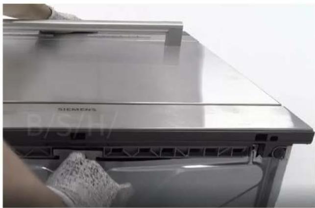
Technical diagram illustrating mechanical assembly steps with labeled components and red annotations indicating features.

Diagram showing three stages of a vehicle door with checkmark and red X marks indicating failure or rejection status.

Interior view of a computer monitor case with visible internal components and a small icon on top (no text or symbols).

Close-up of a mechanical component with a star-shaped badge labeled '20' (no readable text or symbols beyond the badge).

Close-up of a mechanical component with a star-shaped icon labeled '20' (no readable text or symbols beyond the number).

Close-up of a Siemens air conditioner unit with a cloth partially visible, no text or symbols on the device itself.

Close-up of a metallic electronic device with a hand adjusting its top panel (no visible text or symbols).

Close-up of a mechanical device showing internal components with a green cable and a red circle highlighting a small green component (no text or symbols visible).

Close-up of an air conditioner unit showing internal components and wiring (no text or symbols visible).

4.11.2 Assembly

4.12.2 Assembly

Assemble in reverse order.

SIEMENS SC05IB00TE - Assembly - 1

Holder

1 Reel

2 lp

3 Plastic holder

4 Tension spring
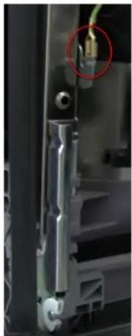
Close-up of a mechanical component with a red circle highlighting a small connector (no visible text or symbols).

Close-up of a gloved hand adjusting a 3D printer's cable and plastic component (no visible text or symbols)

Close-up of a gloved hand holding a wire with multicolored wires, next to a textured black mesh panel (no visible text or symbols)

Interior view of an open appliance showing wiring and components (no visible text or symbols)

Interior view of a compact air conditioner unit showing internal components like fan, vent, and cooling unit (no text or symbols visible)

Close-up of a mechanical component with visible wiring and green material, no text or symbols present

Close-up of a mechanical device with beige hoses and connectors, placed on grass (no visible text or symbols)

Close-up of a mechanical assembly with white components and a beige rod, mounted on a metal frame against a textured green surface (no visible text or symbols)

3D mechanical assembly diagram showing a component mounted on a rail with mounting holes (no text or symbols visible)

Interior view of a stainless steel enclosure with visible wiring and two yellow-circled points of interest (no text or symbols)

Interior view of a cleanroom or industrial space with plastic partitions and ventilation ducts (no visible text or symbols)

Table of contents Click a title to access it
Manual assistant
Powered by Anthropic
Waiting for your message
Product information

Brand : SIEMENS

Model : SC05IB00TE

Category : Dishwasher