
SMS 190 18.0-EC - Saw Flex - Free user manual and instructions
Find the device manual for free SMS 190 18.0-EC Flex in PDF.

| Brand | Flex |
| Model | SMS 190 18.0-EC |
| Product type | Cordless electric miter saw |
| Intended use | Crosscuts, bevel cuts, compound cuts, and grooving in wood and plastics, commercial use |
| Rated voltage | 18 V DC |
| Battery type | AP 18.0/5.0 (Lithium-ion, 5.0 Ah) |
| No-load speed | 5500 rpm |
| Blade diameter | 190 mm (7-1/2 inches) |
| Blade bore | 30 mm |
| Weight (without battery) | 13 kg |
| Battery weight | 0.72 kg |
| Max miter angle | 48° left / 48° right |
| Max bevel angle | 48° left / 48° right |
| Cutting capacity (0° miter, 0° bevel) | 66 mm x 245 mm |
| Integrated laser | Class 1, wavelength 650 nm, power <0.39 mW |
| Sound pressure level | 90 dB(A) |
| Sound power level | 101 dB(A) |
| Total vibration | 0.88 m/s² |
| Operating temperature | -10°C to 40°C |
| Storage temperature | -40°C to 70°C |
| Main functions | Crosscut, miter cut, bevel cut, compound cut, grooving, sliding function |
| Safety | Lower blade guard, clamp, arm lock pin, child safety switch, guide laser |
| Maintenance and cleaning | Regularly clean ventilation slots with dry compressed air; use a soft dry cloth; do not use detergent or alcohol |
| Spare parts and repairability | Exploded views and lists available at www.flex-tools.com; repairs by an authorized service center |
| Included accessories | Clamp, dust bag, hex key, carrying handle, battery (depending on version) |
| Warranty | The manufacturer's warranty is void if the gear housing screws are loosened |
Frequently Asked Questions - SMS 190 18.0-EC Flex
User questions about SMS 190 18.0-EC Flex
0 question about this device. Answer the ones you know or ask your own.
Ask a new question about this device
Download the instructions for your Saw in PDF format for free! Find your manual SMS 190 18.0-EC - Flex and take your electronic device back in hand. On this page are published all the documents necessary for the use of your device. SMS 190 18.0-EC by Flex.
USER MANUAL SMS 190 18.0-EC Flex
natural_image
Technical line drawing of a mechanical assembly with no visible text or symbolsen Original operating instructions....25
natural_image
Technical line drawing of a mechanical assembly with no visible text or symbols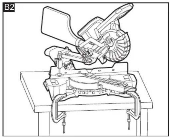
natural_image
Technical line drawing of a mechanical assembly with gears and levers (no text or symbols)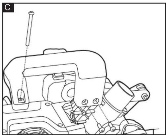
natural_image
Technical line drawing of a mechanical assembly with no visible text or symbols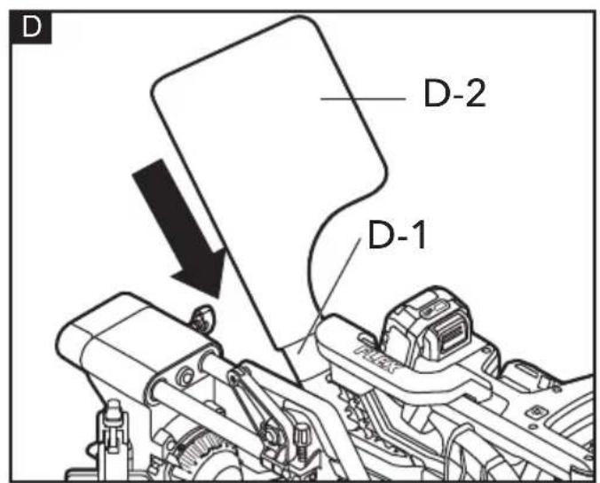

natural_image
Technical line drawing of a mechanical assembly with gears and levers (no text or symbols)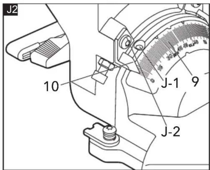
natural_image
Technical line drawing of a mechanical assembly with no visible text or symbols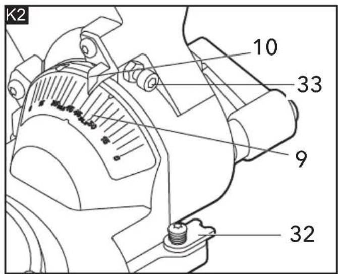
R2
natural_image
Technical line drawing of a mechanical assembly with gears and a base plate (no text or symbols)S
natural_image
Technical line drawing of a mechanical device showing two stages: before and after assembly, with no visible text or symbols.T
natural_image
Technical line drawing of a mechanical assembly with no visible text or symbols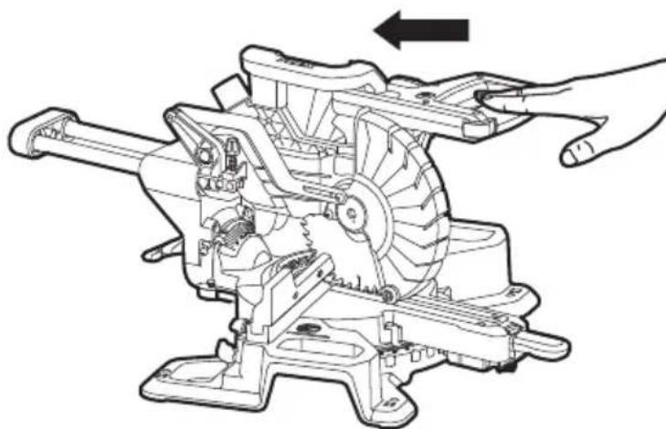
natural_image
Technical line drawing of a mechanical assembly with hands operating a tool (no text or symbols present)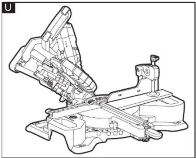
natural_image
Technical line drawing of a mechanical assembly with no visible text or symbols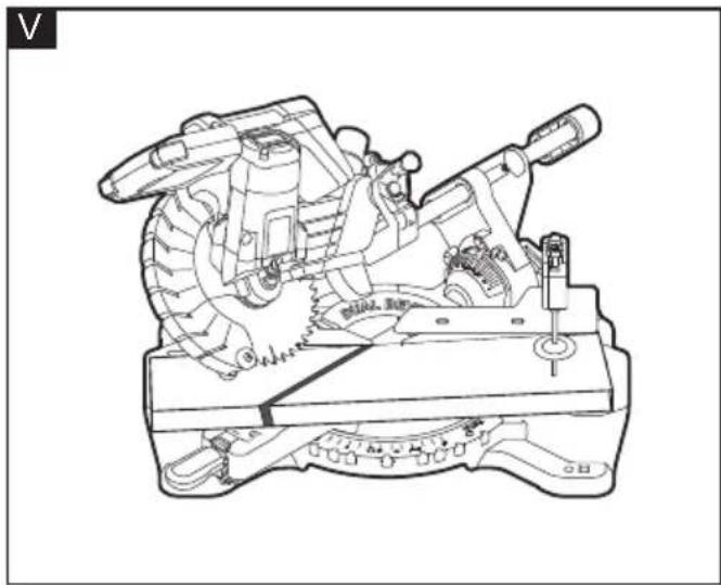
natural_image
Technical line drawing of a mechanical device with gears and levers (no text or symbols)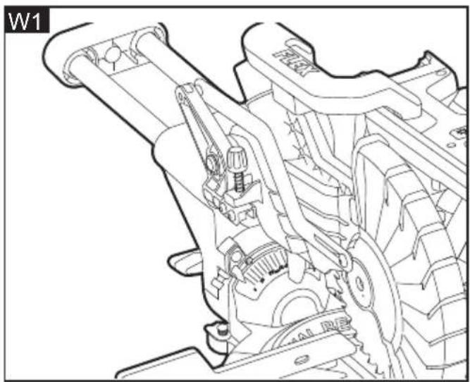
natural_image
Technical line drawing of a mechanical assembly with gears and levers (no text or symbols)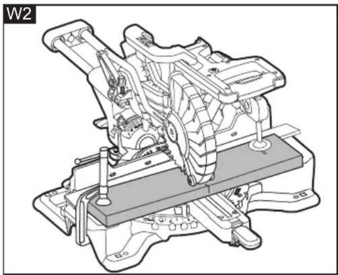
natural_image
Technical line drawing of a mechanical assembly with no visible text or symbols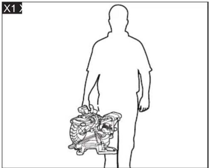
natural_image
Silhouette of a human figure holding a mechanical device (no text or symbols visible)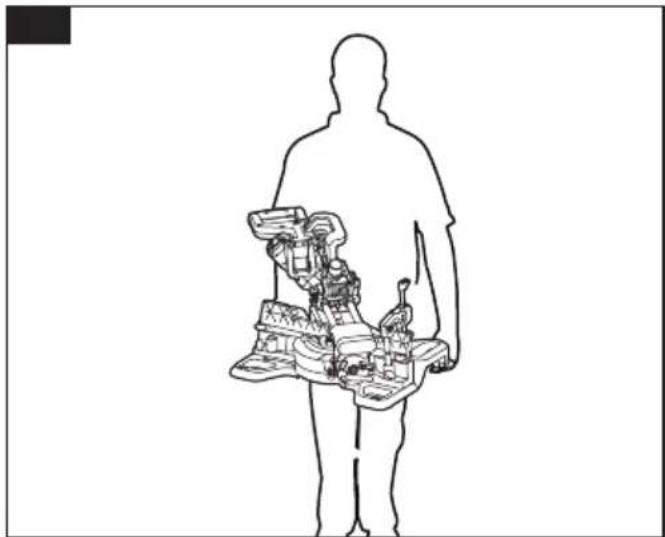
natural_image
Silhouette of a human figure holding a device with internal components (no text or symbols visible)Technical Head Head of Quality
Department (QD)
Symbols used in this manual

WARNING!
Denotes impending danger. Nonobservance of this warning may result in death or extremely severe injuries.

CAUTION!
Denotes a possibly dangerous situation. Nonobservance of this warning may result in slight injury or damage to property.

NOTE
Denotes application tips and important information.
Symbols on the power tool

To reduce the risk of injury, read the operation instructions!

Wear goggles

No-Hands Zone

Class 1 laser product

Disposal information for the old machine (see page 36)!
For your safety

WARNING!
Before using the power tool, please read and follow:
– these operating instructions,
- the "General power tool safety warnings" on Electric motor-operated hand-held tools, transportable tools and lawn and garden machinery - Safety - Part 1: General requirements (EN62841-1),
– the currently valid site rules and the regulations for the prevention of accidents.
This power tool is state of the art and has been constructed in accordance with the acknowledged safety regulations.
Nevertheless, when in use, the power tool may be a danger to life and limb of the user or a third party, or the power tool or other property may be damaged.
The mitre saw may be used only
-asintended,
– in perfect working order.
Faults which impair safety must be repaired
Intended use
The mitre saw is designed
– for commercial use in industry and trade,
- for making cross cutting, bevel cutting and compound cutting
– for cutting wood products and plastics
- to be used with suitable blades
Specific Safety Warnings for Mitre Saw
■ Mitre saws are intended to cut wood or wood-like products, they cannot be used with abrasive cut-off wheels for cutting ferrous material such as bars, rods, suds, etc. abrasive dust causes moving parts such as the lower guard to jam. Sparks form abrasive cutting will burn the lower guard, the kerf insert and other plastic parts.
■ Use clamps to support the workpiece whenever possible. If supporting the workpiece by hand you must always keep your hand at least 100 mm from either side of the saw blade. Do not use this saw to cut pieces that are too small to be securely clamped or held by hand. If your hand is placed too close to the saw blade, there is an increased risk of injury from blade contact.
■ The workpiece must be stationary and clamped or held against both the fence and the table. Do not feed the workpiece into the blade or cut "freehand" in any way. Unrestrained or moving workpieces could be thrown at high speeds, causing injury.
■ Push the saw through the workpiece. Do not pull the saw through the workpiece. To make a cut, raise the saw head and pull it out over the workpiece without cutting, start the motor, press the saw head down and push the saw through the workpiece. Cutting on the pull stroke is likely to cause the saw blade to climb on top of the workpiece and violently throw the blade assembly towards the operator.
■ Never cross your hand over the intended line of cutting either in front or behind the saw blade. Supporting the workpiece "cross handed" i.e. holding the workpiece to the right of the saw blade with your left hand or vice versa is very dangerous.
- Do not reach behind the fence with either hand closer than 100 mm from either side of the saw blade, to remove wood scraps, or for any other reason while the blade is spinning. The proximity of the spinning saw blade to your hand may not be obvious and you may be seriously injured.
- Inspect your workpiece before cutting. If the workpiece is bowed or warped, clamp it with the outside bowed face toward the fence. Always make certain that there is no gap between the workpiece, fence and table along the line of the cut. Bent or warped workpieces can twist or shift and may cause binding on the spinning saw blade while cutting. There should be no nails or foreign objects in the workpiece.
■ Do not use the saw until the table is clear of all tools, wood scraps, etc., except for the workpiece. Small debris or loose pieces of wood or other objects that contact the revolving blade can be thrown with high speed.
- Cut only one workpiece at a time. Stacked multiple workpieces cannot be adequately clamped or braced and may bind on the blade or shift during cutting.
■ Ensure the mitre saw is mounted or placed on a level, firm work surface before use. A level and firm work surface reduces the risk of the mitre saw becoming unstable.
- Plan your work. Every time you change the bevel or mitre angle setting, make sure the adjustable fence is set correctly to support the workpiece and will not interfere with the blade or the guarding system. Without turning the tool "ON" and with no workpiece on the table, move the saw blade through a complete simulated cut to assure there will be no interference or danger of cutting the fence.
■ Provide adequate support such as table extensions, saw horses, etc. for a workpiece that is wider or longer than
the table top. Workpieces longer or wider than the mitre saw table can tip if not securely supported. If the cut-off piece or workpiece tips, it can lift the lower guard or be thrown by the spinning blade.
- Do not use another person as a substitute for a table extension or as additional support. Unstable support for the workpiece can cause the blade to bind or the workpiece to shift during the cutting operation pulling you and the helper into the spinning blade.
■ The cut-off piece must not be jammed or pressed by and means against the spinning saw blade. If confined, i.e. using length stops, the cut-off piece could get wedged against the blade and thrown violently.
■ Always use a clamp or a fixture designed to properly support round material such as rods or tubing. Rods have a tendency to roll while being cut, causing the blade to "bite" and pull the work with your hand into the blade.
■ Let the blade reach full speed before contacting the workpiece. This will reduce the risk of the workpiece being thrown.
If the workpiece or blade becomes jammed, turn the mitre saw off. Wait for all moving parts to stop and disconnect the plug from the power source and/or remove the battery pack. Then work to free the jammed material. Continued sawing with a jammed workpiece could cause loss of control or damage to the mitre saw.
■ After finishing the cut, release the switch, hold the saw head down and wait for the blade to stop before removing the cut-off piece. Reaching with your hand near the coasting blade is dangerous.
Additional Safety Warnings for Mitre Saw
■ Do not make any modifications to the laser equipment.
■ Never make warning signs on the machine unrecognisable.
■ Never stand on the power tool. Serious injuries can occur when the power tool tips over or when inadvertently coming into contact with the saw blade.
■ Make sure that the guard operates properly and that it can move freely. Never lock the guard in place when opened.
■ Never remove cutting remainders, wood chips, etc. from the sawing area while the machine is running. Always guide the tool arm back to the neutral position first and then switch the machine off.
■ Guide the saw blade against the workpiece only when the machine is switched on. Otherwise there is damage of kickback, when the saw blade becomes wedged in the workpiece.
- Keep handles dry, clean, and free from oil and grease. Greasy, oily handles are slippery causing loss of control.
■ Operate the power tool only when the work area to the workpiece is clear of any adjusting tools, wood chips, etc. Small pieces of wood or other objects that come in contact with the rotating saw blade can strike the operator with high speed.
- Keep the floor free of wood chips and material remainders. You could slip or trip.
■ Always firmly clamp the piece to be worked. Do not saw workpieces that are too small to clamp. Otherwise, the clearance of your hand to the rotating saw blade is too small.
■ Use the machine only for cutting the materials listed under Intended Use. Otherwise, the machine can be subject to overload.
If the saw blade should become jammed, switch the machine off and hold the workpiece until the saw blade comes to a complete stop. To prevent kickback, the workpiece may not be moved until after the machine has come to a complete stop. Correct the cause for the jamming of the saw blade before restarting the machine.
■ Do not use dull, cracked, bent or damaged saw blades. Unsharpened or improperly set saw blades produce narrow kerf causing excessive friction, blade binding and kickback.
■ Always use saw blades with correct size and shape (diamond versus round) of arbor holes. Saw blades that do not match the mounting hardware of the saw will run eccentrically, causing loss of control.
■ Do not touch the saw blade after working before it has cooled. The saw blade becomes very hot while working.
■ Never operate the machine without the insert plate. Replace a defective insert plate. Without flawless insert plates, injuries are possible from the saw blade.
■ Store the machine in a safe manner when not being used. The storage location must be dry and lockable. This prevents the machine from storage damage, and from being operated by untrained persons.
- Secure the workpiece. A workpiece clamped with clamping devices or in a vice is held more secure than by hand.
■ Never leave the machine before it has come to a complete stop. Cutting tools that are still running can cause injuries.
■ Instructions to avoid overheating the saw blade tips and, if cutting plastics is permitted, to avoid melting the plastic.
Noise and vibration
The noise and vibration vaues have been determined in accordance with EN62841. The A evaluated noise level of the power tool is typically:
– Sound pressure level L_pA : 90 dB(A);
- Sound power level L_WA : 101 dB(A);
- Uncertainty: K = 3 dB.
– Total vibration value:
- Emission value a_h : 0.88 m/s
– Uncertainty: K= 1.5 m/s

CAUTION!
The indicated measurements refer to new power tools. Daily use causes the noise and vibration values to change.

NOTE
The vibration emission level given in this information sheet has been measured in accordance with a standardised test given in EN62841 and may be used to compare one tool with another. It may be used for a preliminary assessment of exposure. The declared vibration emission level represents the main applications of the tool. However if the tool is used for different applications, with different accessories or poorly maintained, the vibration emission may differ. This may significantly increase the exposure level over the total working period. For a precise estimation of the vibration load the times
should also be considered during which the power tool is switched off or even running, but not actually in use. This may significantly decrease the exposure level over the total working period. Identify additional safety measures to protect the operator from the effects of vibration such as: maintain the tool and the accessories, keep the hands warm, organisation of work patterns.

CAUTION!
Wear ear protection at a sound pressure above 85 dB(A).
Technical specifications
| SMS 19018.0-EC | ||
| Machine Type DC Mitre Saw | ||
| Rated Voltage V d.c 18 | ||
| No Load Speed | RPM(revolutions per min) | 5500 |
| Blade Diameter in(mm) | 7-1/2 in(190mm) | |
| Blade Arbor Hole Diameter | mm 30 | |
| Weight (Without Battery pack) | kg 13 | |
| Battery Ah AP 18.0/5.0 | ||
| Weight battery - AP 18.0/5.0 | kg 0.72 | |
| Laser Wavelength | nm 650 | |
| Laser Power mW <0.39 | ||
| Laser Grade | 1 | |
| Max. Mitre Angle | ° | 48° right, 48° left |
| Max. Bevel Angle | ° | 48° right, 48° left |
| Mitre Detents Left | ° | 0°,15°,22.5°,31.6°,45° |
| Mitre Detents Right | ° | 0°,15°,22.5°,31.6°,45° |
| Bevel Stops Left | ° | 0°,45°,48° |
| Bevel Stops Right | ° | 0°,45°,48° |
| Recommended working temperature | °C | -10°C-40°C |
| Recommended storage temperature | °C | -40°C-70°C |
Cutting Capacities:
| Mitre/Bevel Angle | Height x Width | ||
| Horizontal | Vertical | ||
| 0° | 0° | mm | 66×245 |
| 45° (leftward/rightward) | 0° | mm | 66×172 |
| 0° | 45° (rightward) | mm | 22×245 |
| 0° | 45° (lefttward) | mm | 42×245 |
| 45°(rightward) | 45° mm 22 | ×172 | |
| 45°(lefttward) | 45° mm 42 | ×172 | |
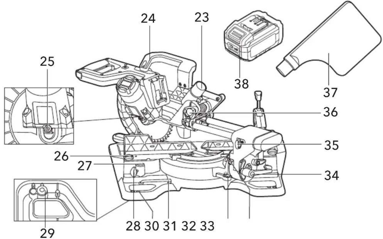
Overview (see figure A)
The numbering of the product features refers to the illustration of the machine on the graphics page.
1 Lock-off Buttons
2 Main Handle
3 On/Off Switch
4 Laser Switch
5 Lower Blade Guard
6 Saw Blade
7 Upper Blade Guard
8 Depth-control Knob
9 Bevel Scale
10 Bevel-angle Indicator
11 Bevel-stop Lever
12 Work Clamp
14 Fixed Fence
15 Saw Base
16 Mitre Table
17 Mitre Scale
13 Sliding Fence(left and right)
18 Mitre Detents
19 Mitre-scale Indicator
20 Insert Plate
21 Mitre-control Lever
22 Laser Len
23 Dust-extraction Port
24 Carrying Handle
25 Spindle-lock Pin
26 Fence-lock Knob(left and right)
27 Work-clamp Mounting Hole(left and right)
28 Work-clamp Lock Knob(left and right)
29 Rubber Foot(4)
30 Mounting Holes(4)
31 Double-ended Allen Wrench
32 45° Bevel Stop
33 Bevel-stop Bolt
34 Bevel-lock Knob
35 Sliding-lock Knob
36 Arm-lock Pin
37 Dust Bag
38 Battery
Assembly

WARNING!
Avoid unintentional starting of the machine, during assembly on the machine, always remove the battery pack from the saw.
Unpacking and checking contents

WARNING!
If any parts are missing, do not turn the switch on until the missing parts are obtained and are installed correctly Unpack the mitre saw and check if all parts listed below:
- Mitre Saw
- Work Clamp
- Dust Bag
- Double-ended Allen Wrench
- Carrying Handle
- Long screw
- Short screws(2)
Tools Needed(not supplied)

Combination square
2.5mm wrench
T25 Torx wrench
5mm wrench
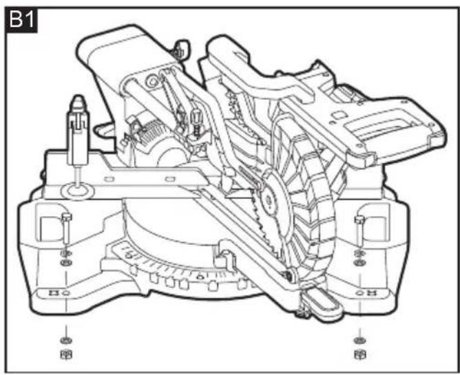
Mounting on a level and stable surface

WARNING!
To ensure safe handling, the machine must be mounted on a level and stable surface (e.g., workbench) prior to using.
Mounting to a Working Surface (see figures B1-B2)
- Fasten the mitre saw to the working surface by using suitable fasteners. The mounting holes 30 serve for this purpose.
- Secure the mitre saw to the working surface by using two commercially available clamps or more.
or
Mounting to a FLEX Saw Stand
This mitre saw can be mounted on FLEX WB 110-260 saw stand, referring to the instruction of saw stand for its installation.

WARNING!
Read all safety warnings and instructions Read all sa included with the saw stand. Included with the saw s observing safety warnings and instructions can cause serious injuries.

WARNING!
Assemble the stand properly before mounting Asset the power tool. Perfect assembly is important in order to prevent the risk of collapsing.
Mounting the Carrying Handle (see figure C)
Align the carrying handle with its mounting area on the saw. Secure the carrying handle in place by using a long screw and two short screws. The small end of the supplied double-ended allen wrench is used for this purpose.
Dust-extraction Port (see figure D)
The dust-extraction port (D-1) accepts a standard vacuum hose (38cm) for dust collection.
It also allows to be connected with dust bag (D-2) for smaller jobs.
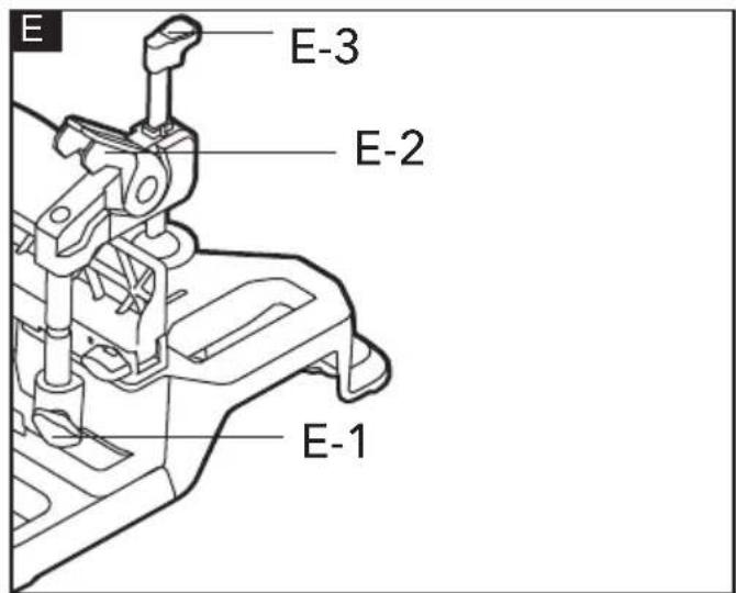
Work Clamp (see figure E)
To ensure optimum working safety, the workpiece must always be firmly clamped.
Do not saw workpieces that are too small to clamp.
Insert the work clamp into the desired mounting hole behind the fence. Tighten the locking knob (E-1) to ensure the lower groove on the rod of work clamp is fully engaged with threaded stud of the locking knob.
- Open the clamping lever (E-2) of the work clamp, lift the hold down clamp (E-3) as far as it will go.
- Rotate the work clamp so that the hold-down clamp is positioned over workpiece as needed.
- Lower the hold-down clamp onto the workpiece.
- Close the clamping lever.
i NOTE
Move the sliding fence toward each side to make sure there is no interference between the work clamp and the sliding fence, if necessary.
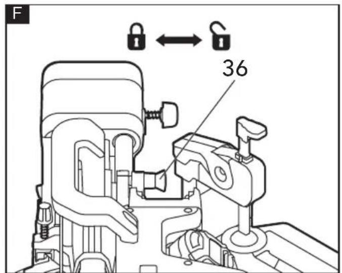
Unlocking/Locking the Saw Arm (see figure F)
To unlock and raise the saw arm (Working Position):
- Firmly grasp the main handle and apply downward pressure while at the same time pulling the arm-lock pin (36) out so that it stops in unlock position.
- Slowly raise the saw arm.
To lock the saw arm(Transport Position):
- Firmly grasp the main handle and apply downward pressure until head stops.
- Push in the arm-lock pin toward the saw, allowing it to lock the saw into place.
i NOTE
Do not use saw to cut while it is in the locked position.
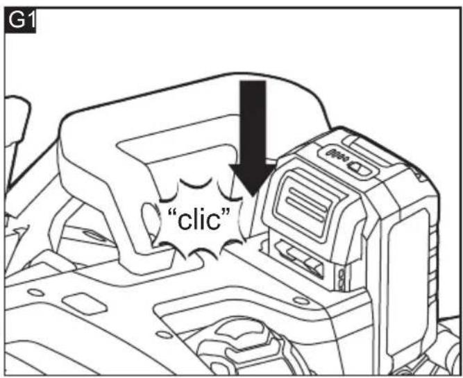
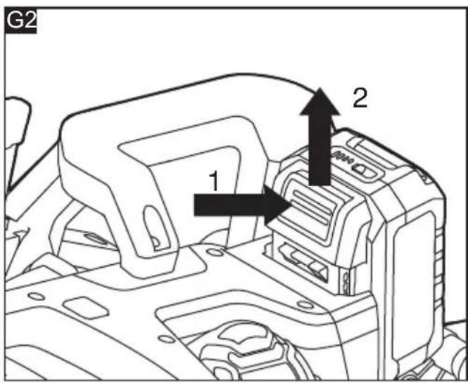
Inserting/replacing the Battery (see figure G1&G2)
Press the charged battery (38) into the power tool until it clicks into place.
To remove, press the release button and pull out the battery.
CAUTION!
When the device is not in use, protect the battery contacts. Loose metal parts may short-circuit the contacts; explosion and fire hazard!
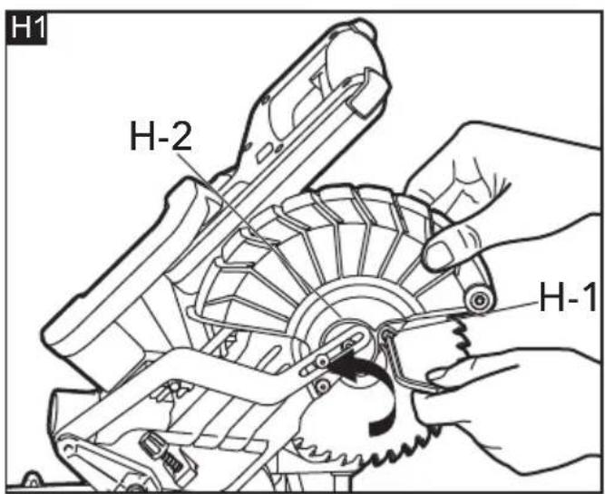
Removal and Installation of the Blade(see figure H1-H3)
WARNING!
Always turn the tool off and remove the battery pack before making any adjustments or assembling parts.
■ Use protective gloves when removing or installing the blade. Do not touch the blade teeth to avoid injury.
Use only a saw blade diameter in accordance with the markings on the saw and information about the bore diameter and the maximum kerf of the saw blade. Use only saw blades that are marked with a speed equal or higher than the speed marked on the tool.
To Remove the Blade
- Raise the saw arm by releasing the arm-lock pin.
- Lift and hold the lower blade guard (5); loosen the blade-bolt guard screw (H-1) with the supplied double-ended allen wrench.
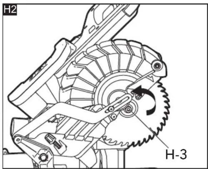
- Rotate the blade-bolt guard (H-2) to expose the blade bolt (H-3).
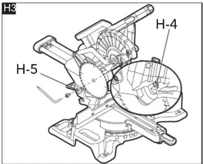
- Press and hold the spindle-lock button (H-4), and rotate the saw blade (6) at the same time until it locks into position.
- Use the wrench to turn the blade bolt clockwise. Remove the blade bolt.
- Remove the outer flange (H-5) and the blade. Wipe the blade flanges and spindle to remove any dust and debris.
To Install the Blade
- Ensure that the inner flange is properly installed in the spindle.
- Match the arrow on the saw blade with the arrow on the upper blade guard (7). Make sure that the teeth of the blade are pointing downward.
-
Fit the saw blade inside the upper blade guard and onto the spindle.
-
Install the outer flange.
- Press and hold the spindle-lock button, and use the wrench to turn the blade bolt counter-clockwise until the lock engages. Securely tighten the blade bolt.
- Rotate the blade-bolt guard into position, and use the wrench to securely tighten the screw by turning it clockwise.
Adjustments
■ Avoid unintentional starting of the machine, Avoid unintentional starting of the machine, during adjustments on the saw, always during adjustments on the saw; always remove the battery pack from the saw. Remove the battery pack from the saw.
NOTE
The mitre saw was completely adjusted at the factory. However, during shipment, slight misalignment may have occurred. Check the following settings and make adjustments, if necessary, prior to using the mitre saw.
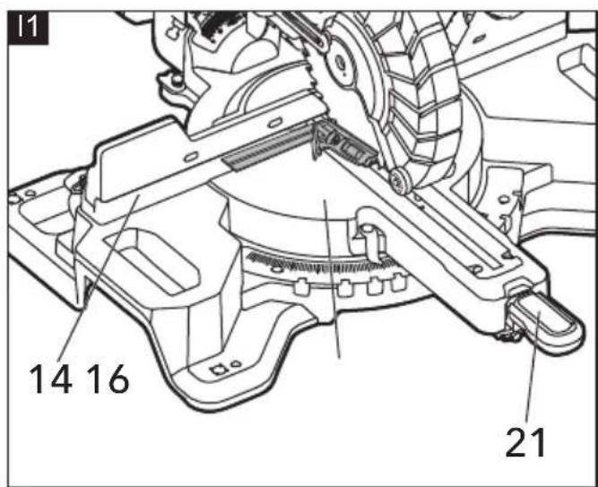
Aligning the Scale for Mitre Angles (see figure I1-I2)
- Position the saw head to the closest position in relation to the fence. And use the arm-lock pin to secure the saw head in place.
- Set the mitre table at 0^ , and set bevel angle of saw head at 0^ .
Checking: (see figure I1)
- Position 90^ corner of a combination square between the fixed fence (14) and the saw blade on the mitre table (16).
The leg of the square must be flush with the saw blade over the complete length.
Adjusting (if necessary): (see figure 12)
- Loosen all three screws (I-1) with the supplied double-ended allen wrench and turn the mitre table together with the mitre scale (17) until the leg of the square is flush with the saw blade over the complete length.
– Retighten the screws again.
When the mitre-angle indicator (19) is not in line with the 0^ mark of the mitre scale after adjusting, loosen the screw (I-2) with a T25 Torx wrench (not included) and align the angle indicator alongside the 0^ mark.
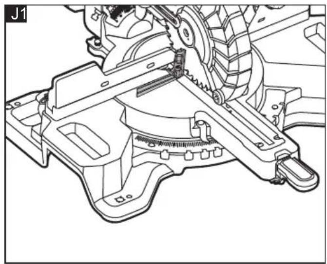
Setting the Standard Bevel Angle 0° (Vertical) (see figure J1-J2)
- Position the saw head to the closest position in relation to the fence. And use the arm-lock
pin to secure the saw head in place.
- Set the mitre table at 0^ , and set bevel angle of saw head at 0^ .
Checking: (see figure J1)
- Position 90° corner of a combination square between the mitre table and the saw blade, ensure it be placed close to fixed fence.
- The leg of the square must be flush with the saw blade over the complete length.
Adjusting (if necessary): (see figure J2)
Loosen the hevel lock knob (34) Avoid unintentional starting of the machine, Adjust the setscrew (1-1) in or out by using g adjustments on the saw, always the supplied double ended allen wrench, ve the battery pack from the saw. until the leg of the square is flush with the saw blade.
- Once the angle is set, retighten the bevel-lock knob.
In case of the bevel-angle indicator (10) is not in line with the 0^ mark of the bevel scale (9) after the adjustment, loosen the screw (J-2) by using a T25 Torx wrench (not included) and align the angle indicator with the 0^ mark.
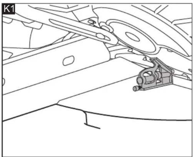
Setting the Standard Bevel Angle 45° (Vertical) (see figure K1 and K2)
NOTE
This mitre saw can be tilted to left or right side. In general, the checking and adjusting method are the same. Right bevel need to rotate the bevel-stop lever (11), that is the only difference between them.
Here raise the right side as an example:
- Position the saw head to the closest position in relation to the fence. And use the arm-lock pin to secure the saw head in place.
- Set the mitre table at 0o.
- Move the right sliding fence (13) all the way out along the horizontal direction.
- Rotate the 45^ stop block (32) completely to the rear of the saw.
- Loosen the bevel-lock knob (34) and rotate the bevel-stop lever (11) to the other side to pull it out.
– (For the left bevel this step should be skipped) - Tilt the tool arm by main handle rightward to the stop (45°).
Checking (see figure K1):
- Place 45° corner of combination square between the saw blade and mitre table. The leg of the square must be flush with the saw blade over the complete length.
Adjusting (see figure K2):
- Adjust by tightening or loosening the bevelstop bolt (33) on the tool with a 5mm hex wrench (not included).
- Retighten the bevel-lock knob and push the bevel-stop lever (11) in.
In case the bevel indicator (10) is not in a line with the 45^ mark of the scale (9), firstly check the 0^ setting for the bevel angle and the angle indicator again. Then repeat the adjustment of the 45^ bevel angle.
Adjusting Mitre-Angle
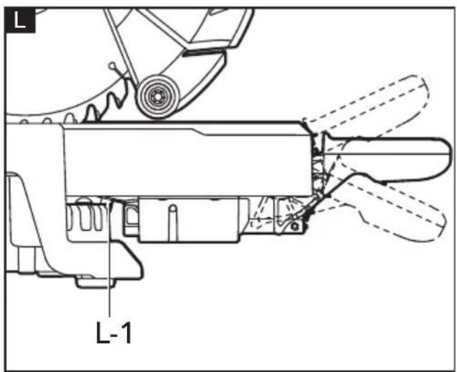
The use of mitre-control lever (see figure L)
The mitre-control lever can be positioned in three positions. If take the horizontal position as a start point, lift it to get upper position. Press it down to get lower position.
Horizontal position
- For the most commonly used angle 0^, 15^, 22.5^, 31.6^ , and 45^ right/left mitre angle, the mitre-detent pin (L-1) can be fully engaged into the notch on the mitre scale.
- For other angle, the mitre - detent pin will override the mitre detents.
Upper position (also known as unlocked position)
- The mitre-detent pin doesn't work anymore, at this moment the mitre table can rotate freely.
Lower position (also known as locked position)
- The mitre table should be secured in place.
Adjusting the mitre-table to the most commonly used angle
- Adjust the mitre-control lever to the upper position and hold it in place, move the mitre table close to the desired most commonly used angle.
- Release the mitre-control lever, it will go back to horizontal position automatically. Hold the mitre-control lever continue to rotate the mitre table toward the desired angle, until the mitre-detent pin is snapped into the detent.
- Press down the mitre-control lever to secure the mitre table in place.
Adjusting the mitre-table to other angle
The mitre angle can be set in the range from
48^ (left side) to 48^ (right side).
- Adjust the mitre-control lever to the upper position and hold it in place, move the mitre table close to the desired angle.
- Press down the mitre-control lever to secure the mitre table in place.
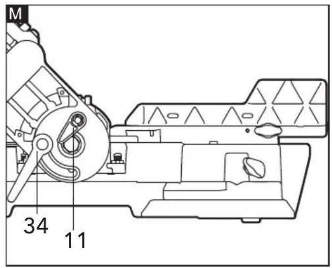
Adjusting Bevel Angles (see figure M)
NOTE
This mitre saw can be tilted to left or right side. In general, the adjusting method are the same, except the bevel-stop lever (11) need to be rotated to let the saw head go to the right side.
Here raise the right bevel as an example:
- Loosen the bevel-lock knob (34).
- Rotate the bevel-stop lever, and place it in rest position.
- Hold the saw arm and tilt to the desired bevel angle.
- Tighten the bevel-lock knob.
i NOTE
The bevel angle of this saw can be set range from 48^ (left side) to 48^ (right side). To get the angle more than 45^ , just simply turn the 45^ stop block (32) completely to the front of the saw.
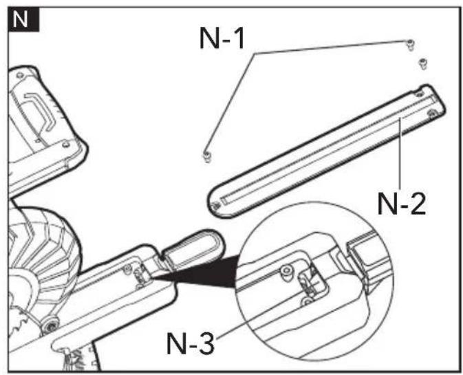
Adjusting the tightness of Mitre-control Lever (see figure N)
i NOTE
This adjustment was made at the factory and, under normal circumstances, it does not require re-adjustment.
To adjust
- Raise the saw arm by releasing the arm-lock pin.
– Lift the mitre-control lever. - Remove the three screws (N-1) securing the insert plate (N-2) with the supplied double-ended allen wrench, and remove the plate and set aside.
- Locate the lock nut (N-3).
- Using a 3mm pin, insert into the hole in the lock nut, adjust by tightening or loosening the lock nut until the proper amount of tension in the mitre-control lever is attained.
– Reinstall the insert plate. - Press the mitre-control lever down to lock the mitre table in place.
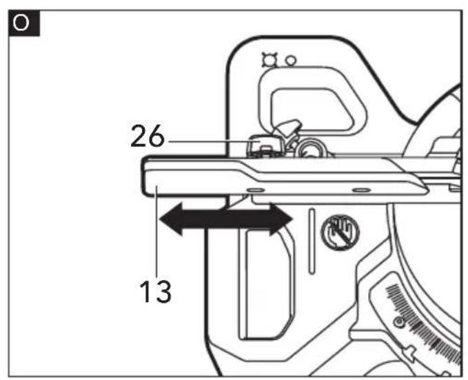
Sliding Fence (see figure O)

CAUTION!
- Adjust and fasten the fences properly before cutting.
The sliding fences (13) are adjustable to accommodate different sized work pieces. Loosen the fence-lock knob (26) on the sliding fences away from the blade to make sure that the blade can not contact the fence.
When making a crosscut or a mitre cut, move the sliding fences closer to the blade to better support the work piece. When making a bevel cut, move fences away from the blade to make sure that the blade can not contact the fence.
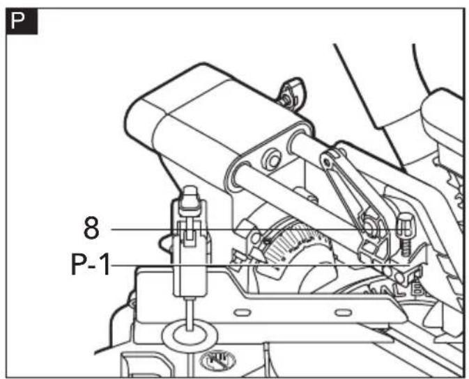
Setting Cutting-Depth(see figure P)
When used, the depth-control knob (8) limits the downward travel of the saw blade when cutting dadoes and other non-through cuts.
To use the depth guide
- With the bottom of the depth-control knob touching the depth stop (P-1), adjust the depth control knob by turning it until the desired depth of cut is attained.
Saw operations
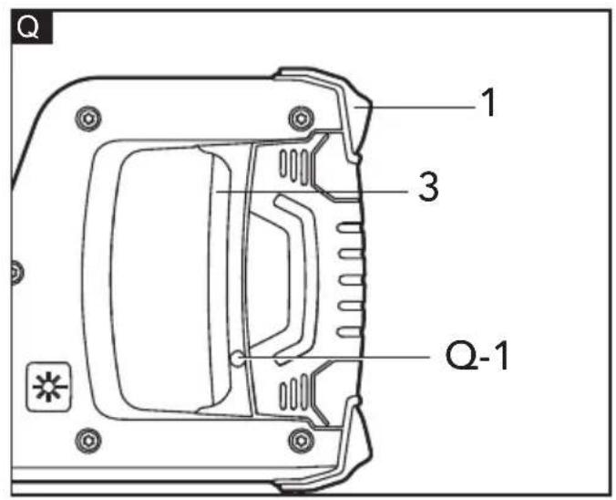
ON/OFF Switch (see figure Q)
For safety, the On/Off switch (3) is designed to prevent accidental starts.
- To turn on the saw, press the lock-off button (1) to disengage the lock, then squeeze the On/Off switch.
- To turn off the saw, release the On/Off switch, and allow the blade to come to a complete stop.

WARNING!
- The blade should reach full speed before it contacts the work piece.
- Make the On/Off trigger switch childproof. Insert a small padlock or cable (not included) through the hole (Q-1) in the On/Off switch, locking the switch and preventing children or other unauthorized users from turning on the saw.
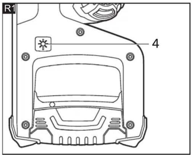
Laser Switch (see figure R1)
To turn on the laser, press the laser switch (4). The laser will automatically turn off after approximately 15 seconds after the laser switch is released.
NOTE: The laser will automatically turn on when the On/Off switch is depressed.
Marking the Cutting Line (see figure R2)
A laser beam indicates the cutting line of the saw blade. This allows for exact positioning of the workpiece for sawing, without having to open the lower guard.
- For this, turn the laser beam on with the laser switch (4).
- Align the cutting mark on your workpiece with reference to the right-hand edge of the laser line.
NOTE: The laser beam adjustments were made at the factory and normally do not require re-adjustment. If required, please contact with FLEX Factory Service Center or Authorized FLEX Service Station
Operation Instructions

WARNING!
Ensure that no interference occurs among the saw blade, saw guard, saw head, fence, clamp during cutting operation, if necessary, re-position the fence and clamp.

WARNING!
If the board is warped, place the convex side against the fence. If the concave edge of the board is against the fence, the board could collapse on the blade at the end of the cut and jam the blade

WARNING!
To avoid serious personal injury, always keep hands outside the "No-Hands Zone," as marked on the saw base. Also, never perform any cutting operation "freehand".
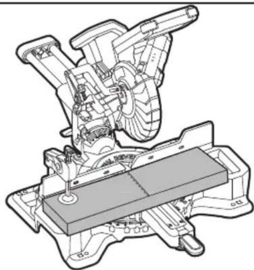
Check the function of lower blade guard (see figure S)

WARNING!
Remove the battery pack from the saw.
a Set the mitre table at 0^ position, secure the mitre table in place. Lock the saw head in the closest position in relation to the fence.
b Set the mitre table at 0^ position, secure the mitre table in place. Lock the saw head in the closest position in relation to the fence.
c Set the bevel angle at 0^ position.
d Properly position the work piece with a thickness equal to the maximum vertical cutting capacity on either side of saw blade. Make sure the work piece is clamped firmly against the table and the fence.
e Release the arm-lock pin, press the saw arm the fully down position, then release the saw arm, it will springs back to the uppermost position. Repeat this process for several times, to ensure the lower blade guard work properly, without binding, jam.
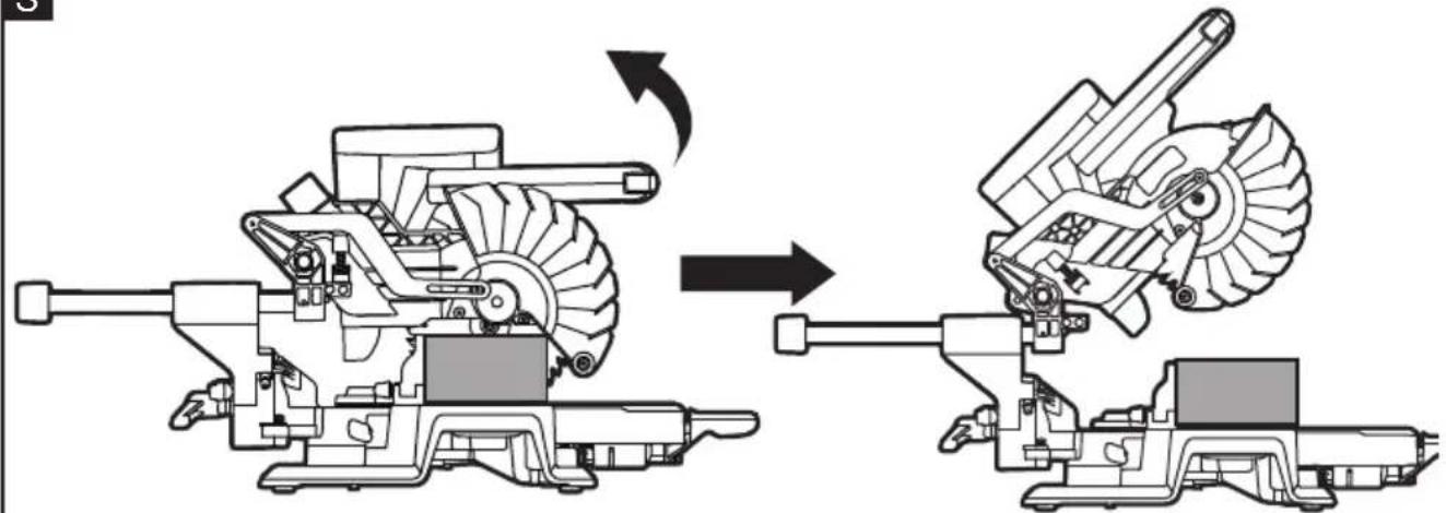
Crosscut and mitre crosscut with or without sliding function (see figure T)
A crosscut is a cut made across the grain of the work piece.
- For narrow workpiece, it can be cut through by a single cut. Perform this kind of cut by using non-sliding cutting method, tighten the sliding -lock knob (35) to fix the saw head in the closest position in relation to fence.
- For wide workpiece, release the sliding-lock knob, so that the saw head can slides along its guide rods from the most distant point to closet position in relation to the fence to perform the cut.
A straight crosscut is a cut made with the mitre table set at the 0^ position. Mitre crosscuts are made with the mitre table set at an angle other than 0^ , either left or right. Mitre angle setting see related section:
Adjusting Mitre-Angle
Here raise a most complicate example: mitre crosscut with sliding function.

WARNING!
Never pull the saw toward you during a cut. The blade can suddenly climb up on top of the work piece and force itself toward you
a Remove the battery pack from the saw.
b Properly position the work piece. Make sure the work piece is clamped firmly against the table and the fence.
c Turn the mitre table to desired angle, and secure the mitre table in place.
d Loosen the sliding-lock knob
e Attach the battery pack to the saw.
f Grasp the main handle and turn on the on/off switch. Always allow the blade to
reach full speed before cutting.
g Lower the saw arm all the way down, and cut through the edge of the work piece.
h Push (but do not force) the saw arm toward the fence all the way to the rear position to complete the cut.
i Release the On/Off switch. Wait until the blade comes to a complete stop before returning the saw arm to the raised position, then remove the work piece.
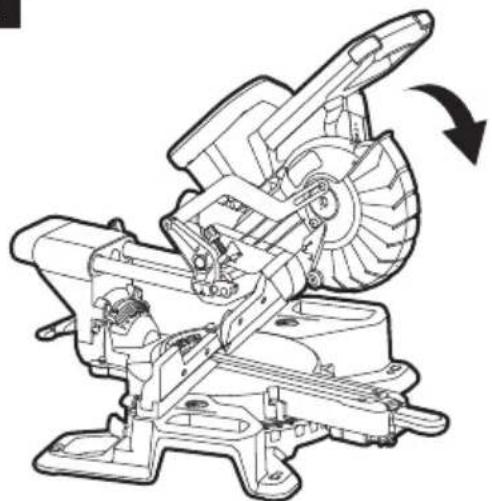
Bevel Cutting (see figure U)
A bevel cut is a cut made across the grain of the work piece with the blade at an angle other than 90^ to the mitre table and the work piece. A straight bevel cut is made with the mitre table set at the 0^ position and with the saw head set at a bevel angle.
Here raise a straight bevel cut without sliding function as an example:
a Remove the battery pack from the saw.
b Properly position the work piece. Make sure the work piece is clamped firmly against the table and the fence.
c Set the mitre table at 0^ position, secure the mitre table in place. Lock the saw head in the closest position in relation to the fence.
d Tilt the saw head to desired angle, tighten the bevel-lock knob.
e Attach the battery pack to the saw.
f Grasp the main handle and turn on the on/off switch. Always allow the blade to reach full speed before cutting.
g Lower the saw arm all the way down, and cut through the work piece.
h Release the On/Off switch. Wait until the blade comes to a complete stop before returning the saw arm to the raised position, then remove the work piece.
Compound Cutting (see figure V)
A compound mitre cut is a cut made using a mitre angle and a bevel angle at the same time.
a Remove the battery pack from the saw.
b Properly position the work piece. Make sure the work piece is clamped firmly against the table and the fence.
c Rotate the mitre table to desired angle and secure the mitre table in place. Lock the saw head in the closest position in relation to the fence.
d Tilt the saw head to desired angle, tighten the bevel-lock knob.
e Attach the battery pack to the saw.
f Grasp the main handle and turn on the on/off switch. Always allow the blade to reach full speed before cutting.
g Lower the saw arm all the way down, and cut through the work piece.
h Release the On/Off switch. Wait until the blade comes to a complete stop before returning the saw arm to the raised position, then remove the work piece.
Cutting grooves (see figure W1, W2)
a Remove the battery pack from the saw
b See the related section :Setting Cutting-Depth to set the desired depth of cut
c Space the work piece away from the fence with a wooden spacer. This will allow for a complete groove to be cut. Be sure the work piece is fully supported.
d Attach the battery pack to the saw.
e Cut the two outside edges of the groove.
f To create the groove, use a wood chisel or make multiple passes with a router to remove the material between the outside edges.
Transporting

WARNING!
Remove the battery pack from the saw before transporting mitre saw to avoid possible injury.
Preparing to lift the saw
- Set the bevel angle at 0^ and lock it in place, using the bevel-lock knob.
- Turn the mitre table to either 45^ right or 45^ left and lock it in place with the mitre-control lever.
- Set the saw head to the closest position in relation to the fence.
- Lock the head assembly in the transport position with the arm-lock pin.
Lift the saw by the carrying handle (see figure X1)
Grip the saw by the carrying handle. Continue to lift and transport comfortably.
Lift the saw by the side carry handles (see figure X2)
Use upright, good posture and grip the two handle areas beneath the base.
Maintenance and care

WARNING!
Remove the battery before carrying out any work on the power tool.
Cleaning
■ Regularly clean the power tool and ventilation slots. Frequency of cleaning is dependent on the material and duration of use.
■ Regularly blow out the housing inferior and motor with dry compressed air.
■ For safe and proper operation, always keep the tool and its ventilation slots clean.
■ Always wear safety goggles or safety glasses with side shields when blowing dust. If operation is dusty, also wear a dust mask.
■ Always use only a soft, dry cloth to clean your mitre saw; never use detergent or alcohol.
Gears

NOTE
Do not loosen the screws on the gear head during the warranty period. Non-compliance will deem the guarantee obligations of the manufacturer null and void.
Repairs
Repairs may be carried out by an authorised customer service centre only.
Spare parts and accessories
For other accessories, see the manufacturer's catalogues.
Exploded drawings and spare-part lists can be found on our homepage:
www.flex-tools.com
Disposal information

WARNING!
Render redundant power tools unusabte:
- mains operated power tool by removing the power cord,
- battery operated power tool by removing the battery.

EU countries only
Do not throw electric power tools into the household waste!
In accordance with the European Directive 2012/19/EC on Waste Electrical and
Electronic Equipment and transposition into national law used electric power tools must be collected separately and recycled in an environmentally friendly manner.

Raw material recovery instead of waste disposal.
Device, accessories and packaging should be recycled in an environmentally friendly manner. Plastic parts are identified for recycling according to material type.

WARNING!
Do not throw batteries into the household waste, fire or water. Do not open used batteries.
EU countries only:
In accordance with Directive 2006/66/EC defective or used batteries must be recycled.

NOTE
Please ask your dealer about disposal options!
C €-Declaration of Conformity
We declare under our sole responsibility that the product described under "Technical specifications" conforms to the following standards or normative documents:
EN 62841 in accordance with the regulations of the directives 2014/30/EU, 2006/42/EC, 2011/65/EU.
Responsible for technical documents:
Technical Head Head of Quality
Department (QD)
Exemption from liability
The manufacturer and his representative are not liable for any damage and lost profit due to interruption in business caused by the product or by an unusable product. The manufacturer and his representative are not liable for any damage which was caused by improper use of the product or by use of the product with products from other manufacturers.
Peter Lameli Klaus Peter Weinper Technical Head Head of Quality
Department (QD)
Technical Head Head of Quality
Department (QD)
Peter Lameli Klaus Peter Weinper Technical Head Head of Quality Department
(QD)
Peter Lameli Klaus Peter Weinper Technical Head Head of Quality
Department (QD)
Technical Head Head of Quality
Department (QD)
Technical Head Head of Quality
Department (QD)
Technical Head Head of Quality
Department (QD)
Peter Lameli Klaus Peter Weinper Technical Head Head of Quality Department
(QD)
Here raise a straight bevel cut without sliding function as an example:
Peter Lameli Klaus Peter Weinper Technical Head Head of Quality Department
Peter Lameli Klaus Peter Weinper Technical Head Head of Quality Department
(QD)
Peter Lameli Klaus Peter Weinper Technical Head Head of Quality
Department (QD)
Technical Head Head of Quality
Department (QD)
Peter Lameli Klaus Peter Weinper Technical Head Head of Quality
Department (QD)
Technical Head Head of Quality Department (QD)
Peter Lameli Klaus Peter Weinper Technical Head Head of Quality
Department (QD)
Peter Lameli Klaus Peter Weinper Technical Head Head of Quality Department
Peter Lameli Klaus Peter Weinper Technical Head Head of Quality
Department (QD)
Technical Head Head of Quality
Department (QD)
Peter Lameli Klaus Peter Weinper Technical Head Head of Quality
Department (QD)
Peter Lameli Klaus Peter Weinper Technical Head Head of Quality Department
(QD)
Peter Lameli Klaus Peter Weinper Technical Head Head of Quality Department
Peter Lameli Klaus Peter Weinper Technical Head Head of Quality Department
Technical Head Head of Quality Department (QD)
34 because framed psychoشطب
35 Malaysia بالملكة
36 إبرة قفل الذراع
37 حقبة الغبار
38 البطارية


- Symbols used in this manual
- WARNING!
- CAUTION!
- NOTE
- Symbols on the power tool
- For your safety
- Intended use
- Specific Safety Warnings for Mitre Saw
- Additional Safety Warnings for Mitre Saw
- Noise and vibration
- Overview (see figure A)
- Assembly
- Unpacking and checking contents
- Tools Needed(not supplied)
- Mounting on a level and stable surface
- Mounting to a Working Surface (see figures B1-B2)
- or
- Mounting to a FLEX Saw Stand
- Mounting the Carrying Handle (see figure C)
- Dust-extraction Port (see figure D)
- Work Clamp (see figure E)
- i NOTE
- Unlocking/Locking the Saw Arm (see figure F)
- To unlock and raise the saw arm (Working Position):
- To lock the saw arm(Transport Position):
- Inserting/replacing the Battery (see figure G1&G2)
- Removal and Installation of the Blade(see figure H1-H3)
- To Remove the Blade
- To Install the Blade
- Adjustments
- Aligning the Scale for Mitre Angles (see figure I1-I2)
- Checking: (see figure I1)
- Adjusting (if necessary): (see figure 12)
- Setting the Standard Bevel Angle 0° (Vertical) (see figure J1-J2)
- Checking: (see figure J1)
- Adjusting (if necessary): (see figure J2)
- Setting the Standard Bevel Angle 45° (Vertical) (see figure K1 and K2)
- Checking (see figure K1):
- Adjusting (see figure K2):
- Adjusting Mitre-Angle
- The use of mitre-control lever (see figure L)
- Horizontal position
- Upper position (also known as unlocked position)
- Lower position (also known as locked position)
- Adjusting the mitre-table to the most commonly used angle
- Adjusting the mitre-table to other angle
- Adjusting Bevel Angles (see figure M)
- Adjusting the tightness of Mitre-control Lever (see figure N)
- To adjust
- Sliding Fence (see figure O)
- Setting Cutting-Depth(see figure P)
- To use the depth guide
- Saw operations
- ON/OFF Switch (see figure Q)
- Laser Switch (see figure R1)
- Marking the Cutting Line (see figure R2)
- Operation Instructions
- Check the function of lower blade guard (see figure S)
- Crosscut and mitre crosscut with or without sliding function (see figure T)
- Bevel Cutting (see figure U)
- Compound Cutting (see figure V)
- Cutting grooves (see figure W1, W2)
- Transporting
- Preparing to lift the saw
- Lift the saw by the carrying handle (see figure X1)
- Lift the saw by the side carry handles (see figure X2)
- Maintenance and care
- Cleaning
- Gears
- Repairs
- Spare parts and accessories
- Disposal information
- Raw material recovery instead of waste disposal.
- C €-Declaration of Conformity
- Exemption from liability
Brand : Flex
Model : SMS 190 18.0-EC
Category : Saw