
C8FSHG - Saw HiKOKI - Free user manual and instructions
Find the device manual for free C8FSHG HiKOKI in PDF.

| Brand | HiKOKI |
| Model | C8FSHG |
| Product Type | Radial miter saw |
| Dimensions (L × W × H) | 528 mm × 725 mm × 495 mm |
| Net Weight | 13.8 kg |
| Supply Voltage | 110 V~ or 230 V~ depending on region |
| Power Consumption | 1030 W (110 V) / 1100 W (230 V) |
| No-Load Speed | 5300 min⁻¹ |
| Compatible Blade Diameter | 216 mm (bore 30 mm) |
| Laser Guide | Class 1M, <0.39 mW, 400-700 nm |
| Max Cutting Capacity (straight) | Height 65 mm, width 305 mm (without anchor plate) |
| Miter Range | Left 0° to 48°, Right 0° to 48° |
| Bevel Range | Left 0° to 47°, Right 0° to 2° |
| Sliding System | Sliding carriage for wide cuts |
| Included Accessories | TCT blade 216 mm, dust bag, vise, support, 13 mm wrench, handle |
| Maintenance | Monthly lubrication, compressed air cleaning, carbon brush replacement |
| Warranty | Compliant with regulations, does not cover misuse |
Frequently Asked Questions - C8FSHG HiKOKI
User questions about C8FSHG HiKOKI
0 question about this device. Answer the ones you know or ask your own.
Ask a new question about this device
Download the instructions for your Saw in PDF format for free! Find your manual C8FSHG - HiKOKI and take your electronic device back in hand. On this page are published all the documents necessary for the use of your device. C8FSHG by HiKOKI.
USER MANUAL C8FSHG HiKOKI
natural_image
Technical line drawing of a mechanical device with gears and levers (no text or symbols)
en Handling instructions
de Bedienungsanleitung
fr Mode d'emploi
it Istruzioni per l'uso
nl Gebruiksaanwijzing
es Instrucciones de manejo
pt Instruções de uso
sv Bruksanvisning
da Brugsanvisning
no Bruksanvisning
fi Käyttöohjeet
el Οδηγίες χειρισμού
pl Instrukcja obsługi
hu Kezelési utasítás
cs Návod k obsluze
tr Kullanım talimatları
ro Instructiuni de utilizare
① Navodila za rokovanje
sk Pokyny na manipuláciu
bg Инструкция за експлоатация
sr Uputstvo za rukovanje
hr Upute za rukovanje
text_image
Technical diagram of a mechanical device with numbered components for identification and assembly reference.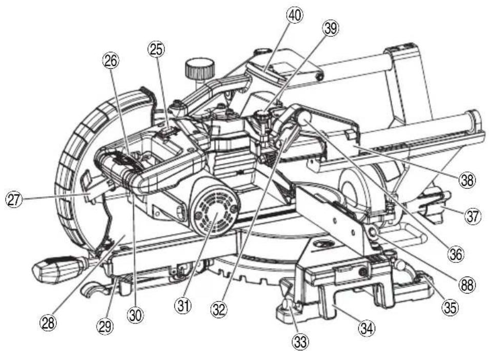
text_image
Technical diagram of a mechanical assembly with numbered components for identification2
text_image
Technical diagram of a mechanical assembly with numbered components labeled ② and ③63
text_image
4 - Ø9 mm 230 mm 214 mm 214 mm4
text_image
Technical diagram of a vehicle suspension system with numbered components labeled 45, 46, and 47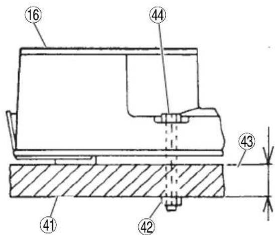
text_image
⑯ ⑭ ④ ④3 ④1 ④25
text_image
Technical diagram of a mechanical device with numbered components and an inset close-up view showing internal components.6
text_image
Technical diagram of a mechanical assembly with numbered annotations pointing to components 8 and 51.7
text_image
Technical diagram of a mechanical device with numbered parts and an inset close-up view highlighting internal components.8
text_image
Technical diagram of a mechanical assembly with numbered components labeled 17, 19, 29, and 54.9
text_image
③9 ⑤5 ③2 a10
text_image
57 28 21 a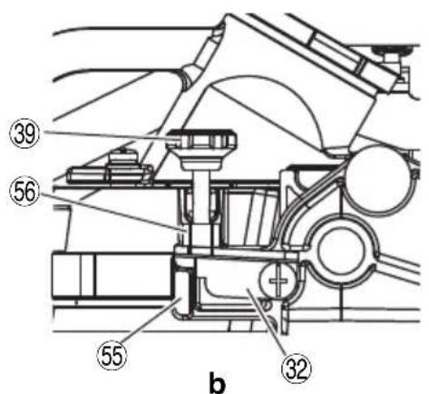
text_image
39 56 55 32 b
text_image
57 28 21 b11
text_image
Technical diagram of a mechanical assembly with numbered components and directional arrow indicating motion or force12
natural_image
Technical line drawing of a mechanical device with labeled component (6), no readable text or symbols present.13 14
text_image
Technical diagram of a mechanical device with numbered parts labeled 19, 20, and 29
text_image
Technical diagram showing a mechanical assembly with labeled parts and a vertical component with numbered annotations.
text_image
62 63 23
text_image
23 63 6217 18
text_image
(23)
text_image
Technical diagram of a mechanical assembly with numbered components labeled 64 and 23
text_image
23 64
natural_image
Technical line drawing of a robotic arm operating a workbench with tool, no visible text or symbols19
text_image
Technical diagram showing mechanical assembly with labeled parts and directional arrows indicating motion or movement.20 21
text_image
Technical diagram of a mechanical assembly with numbered components labeled 25, 26, and 67.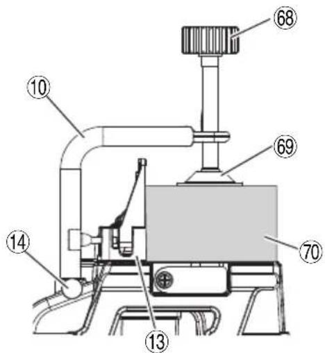
text_image
Technical diagram of a mechanical device with numbered components labeled 68, 69, 70, 10, 13, and 14.22
text_image
a b 28 71 a 72 b 71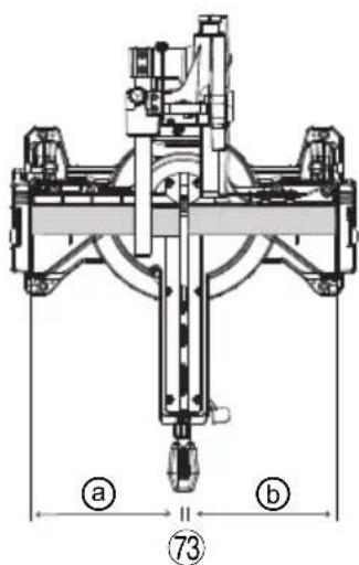
text_image
a 73 b23
text_image
1 ⑦④ 2 3 ⑦⑥ 2 ⑦⑤ 6024

text_image
Technical diagram of a mechanical assembly with numbered components labeled 71 and 3725
text_image
Technical diagram of a mechanical assembly with numbered components and directional arrows indicating motion or movement.26
text_image
80 a b27
text_image
Technical diagram of a mechanical assembly with numbered components, likely an engine or pump assembly.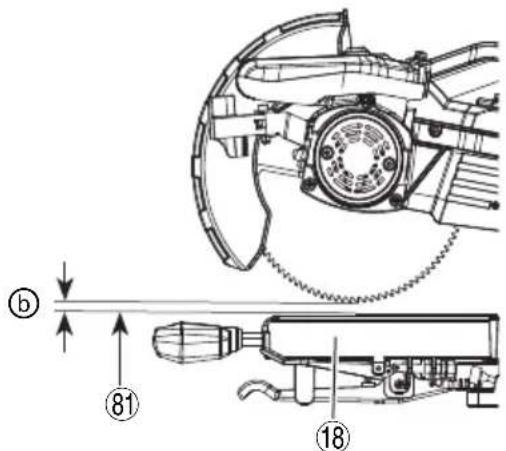
text_image
Technical diagram of a mechanical assembly with labeled parts and directional arrows indicating motion or movement.28
text_image
⑩ ⑪ ⑧3 ② ⑧2 ⑬ ⑬a
text_image
⑩ ⑪ ⑧₄ ⑧₃ ⑧₃ ⑧₂b
29
text_image
Technical diagram of a mechanical device with numbered annotations pointing to componentsa
text_image
Technical diagram of a helmet with numbered parts and labeled parts 85 and 86b
text_image
1 89 88 87C
text_image
28 89 87 90d
30
text_image
91 6 mm 17 mm 92 110V 463 230V C 92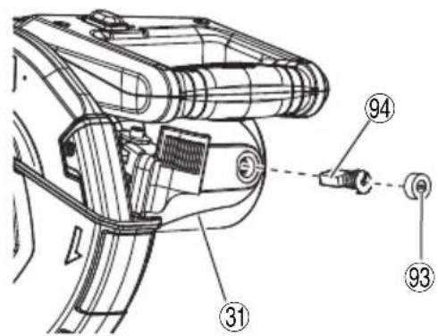
text_image
Technical diagram of a mechanical device with numbered components and labeled parts31
text_image
Technical diagram of a mechanical device with numbered parts and a spray gun icon, likely illustrating a precision or welding process.| English Deutsch Français Italiano | ||||
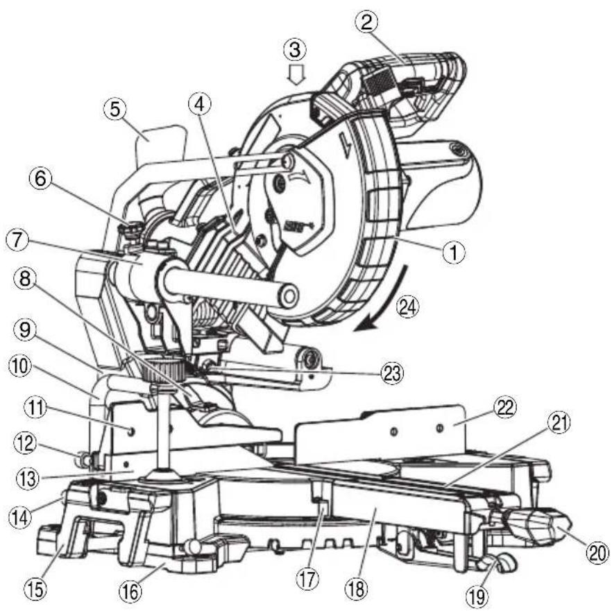
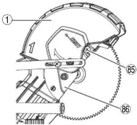
| 1 | Lower guard Unterer Schutz | Carénage inférieur Protezione inferiore | ||
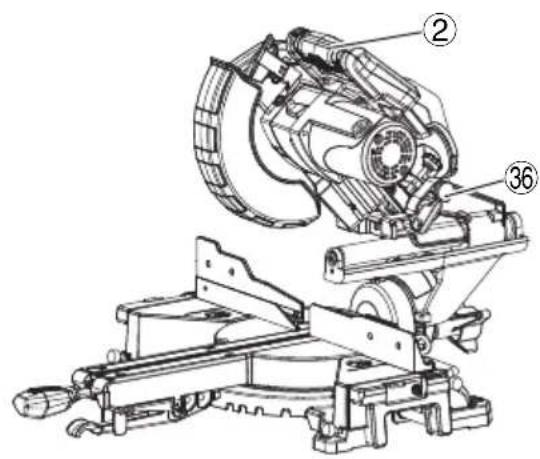
| 2 | Switch handle | Schaltergriff | Poignée de contacteur | Manico di commutazione |
| 3 | Motor head Motorkopf Tête du moteur Testa del motore | |||
| 4 | Gear case Getriebegehäuse | Carter d'engrenage Cassa ingranaggi | ||
| 5 | Dust bag | Staubbeutel | Sac à poussière | Sacca per la polvere |
| 6 | Slide securing knob | Führungssicherungsknopf | Bouton de fi xation coulissant | Manopola di fi ssaggio slitta |
| 7 | Slide carriage | Führungsträger | Chariot coulissant | Carrello slitta |
| 8 | Bevel pointer | Schrägschnittanzeiger | Pointe de biseau | Puntatore smussatura |
| 9 | Holder (A) Halter (A) | Support (A) | Supporto (A) | |
| 10 | Vise assembly | Schraubstocksatz | Ensemble de l'étau | Gruppo morsa |
| 11 | Sub fence Hilfsgitter | Butée secondaire | Guida secondaria | |
| 12 | Lock knob Sperrknopf | Bouton de verrouillage Manopola di blocco | ||
| 13 | Fence (A) | Gitter (A) | Butée (A) | Guida di appoggio (A) |
| 14 | Vise lock knob | Schraubstocksperrknopf | Bouton de verrouillage de l'étau | Manopola di blocco morsa |
| 15 | Left extension table | Linker Anbautisch | Plateau de rallonge gauche | Tavola di estensione sinistra |
| 16 | Base | Basis | Base | Base |
| 17 | Miter pointer Gehrungsanzeiger Pointe d'onglet | Puntatore quartabuono | ||
| 18 | Turntable | Drehscheibe | Plateau tournant | Piatto girevole |
| 19 | Positive stop locking lever | Sperrhebel für den Festanschlag | Levier de verrouillage d'arrêt positif | Leva di blocco arresto positivo |
| 20 | Miter handle | Gehrungsgriff | Poignée d'onglet | Manico per quartabuono |
| 21 | Table insert | Tischeinsatz | Plaque d'insertion | Inserimento tavola |
| 22 | Fence (B) | Gitter (B) | Butée (B) | Guida di appoggio (B) |
| 23 | Laser marker | Lasermarker | Marqueur laser | Marcatore laser |
| 24 | Rotation direction | Drehrichtung | Sens de rotation | Direzione di rotazione |
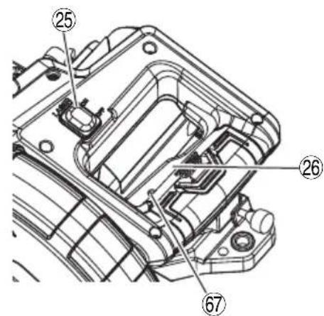
| 25 | Laser marker switch | Schalter für Lasermarker | Contacteur de marqueur laser | Interruttore marcatore laser |
| 26 | Trigger switch | Auslöseschalter | Interrupteur à détente | Interruttore a grilletto |
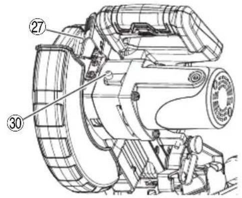
| 27 | Blade guard locking lever | Sperrhebel für den Sägeblattschutz | Levier de verrouillage du protège-lame | Leva di blocco protezione lama |
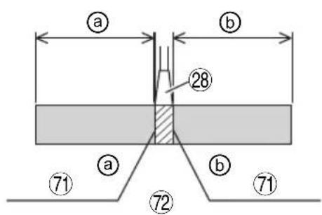
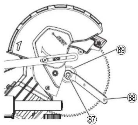
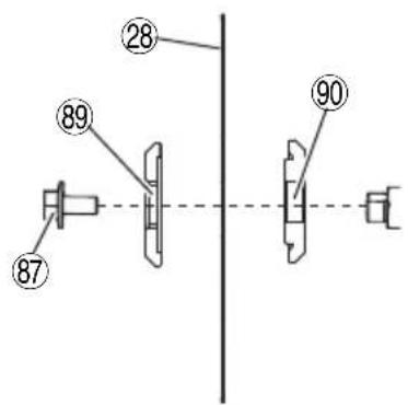
| 28 | Blade | Sägeblatt | Lame | Lama |
| 29 | Quick-cam locking lever | Schnellspannhebel | Levier de verrouillage à came rapide | Leva di blocco camma rapida |
| 30 | Spindle lock | Spindelsperre Verrouillage de broche Blocco dell'alberino | ||
| 31 | Motor | Motor | Moteur | Motore |
| 32 | Anchor plate | Ankerplatte Plaque d'ancrage Piastra di ancoraggio | ||
| 33 | Extension wing lock knob | Verriegelungsknopf für den Anbaufl ügel | Bouton de blocage de la rallonge | Manopola di blocco ala di estensione |
| 34 | Right extension table | Rechter Anbautisch | Plateau de rallonge droit | Tavola di estensione destra |
| 35 | Mounting hole | Montagebohrung | Trou de montage | Foro di montaggio |
| 36 | Locking pin | Sicherungsstift | Goupille de verrouillage | Perno di bloccaggio |
| 37 | Bevel lock knob | Schrägschnitt-Verriegelungsknopf | Bouton de blocage de biseau | Manopola di blocco smussatura |
| 38 | Hinge | Scharnier | Charnière | Cardine |
| 39 | Stop knob Anschlagknopf Bouton d'arrêt Manopola di arresto | |||
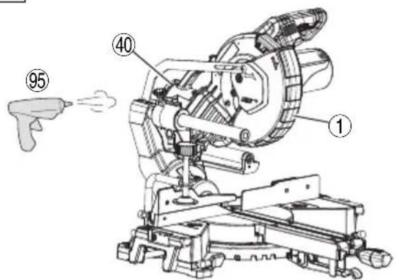
| 40 | Dust port | Anschluss für Staubabsaugung | Sortie d'évacuation de poussière | Porta per la polvere |
| 41 | Work bench Werkbank Établi Banco di lavoro | |||
| 42 | 8 mm nut 8-mm-Mutter Écrou de 8 mm Dado da 8 mm | |||
| 43 | 25 mm thick work bench 25 mm dicke Werkbank | Établi de 25 mm d'épaisseur | Banco di lavoro da 25 mm di spessore | |
| 44 | 8 mm nut 8-mm-Mutter Écrou de 8 mm Dado da 8 mm | |||
| 45 | Holder Halter Support Supporto | |||
| 46 | Hole Loch Trou Foro | |||
| 47 | Screw | Schraube | Vis | Vite |
| 48 | Combination square | Kombi-Winkelmaß | Équerre combinée | Squadra universale |
| 49 | Lock nut Sicherungsmutter | Contre-écrou | Controdado | |
| 50 | Adjustment bolt | Einstellschraube | Boulon de réglage | Bullone di regolazione |
| 51 | Bevel pointer screw | Schrägschnittzeigerschraube | Vis à pointe biseautée | Vite puntatore smussatura |
| 52 | Lock nut Sicherungsmutter | Contre-écrou | Controdado | |
| 53 | Bolt | Schraube | Boulon | Bullone |
| 54 | Screw | Schraube | Vis | Vite |
| 55 | Stop block | Anschlagblock | Bloc d'arrêt | Blocco di arresto |
| 56 | Stop seat | Anschlagsitz | Butée du siège Sede di arresto | |
| 57 | 4 mm machine screw | 4-mm-Maschinenschraube | Vis à métaux de 4 mm | Vite da macchina da 4 mm |
| 58 | Laser line | Laserlinie | Ligne de laser Linea laser | |
| 59 | Cutting line | Schnittlinie | Ligne de coupe | Linea di taglio |
| 60 | Workpiece | Werkstück | Pièce à usiner Pezzo da lavorare | |
| 61 | Top view | Draufsicht Vue de dessus Vista superiore | ||
| 62 | Rivet | Stift | Rivet | Rivet |
| 63 | Laser housing Lasergehäuse Boîtier laser | Alloggiamento laser | ||
| 64 | Set screw | Einstellschraube | Vis de réglage | Vite di fissaggio |
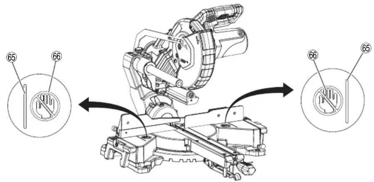
| 65 | Line | Linie | Ligne | Linea |
| 66 | Warning sign | Warnschild | Signe d'avertissement | Segnale di avvertenza |
| 67 | Hole Loch Trou Foro | |||
| 68 | Knob | Knopf Bouton | Manopola | |
| 69 | Vise plate | Schraubstockplatte | Plaque d'étau | Piastra della morsa |
| 70 | Workpiece | Werkstück | Pièce à usiner Pezzo da lavorare | |
| 71 | Marking (pre-marked) | Markierung (vormarkiert) | Marquage (pré-marqué) | Marcatura (pre-marcata) |
| 72 | (Front view) | (Vorderansicht) | (vue de face) | (Vista anteriore) |
| 73 | Adjusting line | Einstelllinie | Ligne de réglage | Linea di regolazione |
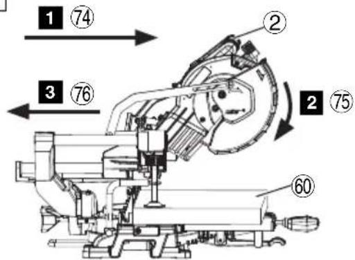
| 74 | Pull forward | Nach vorn ziehen | Tirer vers l'avant | Tirare in avanti |
| 75 | Press down | Herunterdrücken | Appuyer vers le bas | Premere in basso |
| 76 | Push backward | Nach hinten drücken | Pousser en arrière | Spingere indietro |
| 77 | Bevel scale | Schrägschnittskala | Échelle de biseau | Scala di smussatura |
| 78 | Miter scale | Gehrungsskala Échelle à onglets Scala di quartabuono | ||
| 79 | Turn the turntable | Drehen Sie die Drehscheibe | Tourner le plateau tournant | Ruotare il piatto girevole |
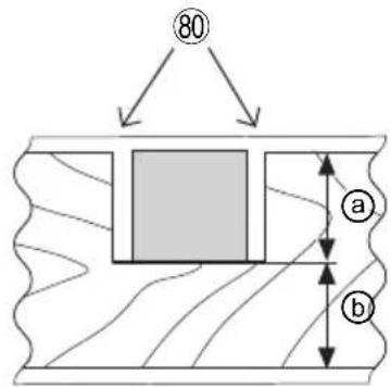
| 80 | Cut grooves with saw blade | Nuten mit dem Sägeblatt schneiden | Couper les rainures avec une lame de scie | Tagliare le scanalature con la lama sega |
| 81 | Bottom line of the groove Untere Linie der Nut | Ligne inférieure de la rainure | Linea inferiore della scanalatura | |
| 82 | Aluminum sash Aluminiumrahmen Cadre en aluminium Telaio in alluminio | |||
| 83 | Wood plate Holzplatte Plaque en bois Piastra di legno | |||
| 84 | Clamp Klemme Dispositif de serrage Morsetto | |||
| 85 | Cover plate screw | Schraube für die Abdeckplatte | Vis de couvercle Vite piastra coperchio | |
| 86 | Cover plate Abdeckplatte Couvercle Piastra coperchio | |||
| 87 | 8 mm bolt | 8-mm-Schraube | Boulon de 8 mm | Bullone da 8 mm |
| 88 | Blade spanner | Sägeblattschlüssel | Clé à lame | Chiave per lama |
| 89 | Washer (B) Unterlegscheibe (B) Rondelle (B) | Rondella (B) | ||
| 90 | Washer (A) | Unterlegscheibe (A) | Rondelle (A) | Rondella (A) |
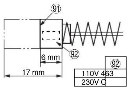
| 91 | Wear limit line | Verschleißgrenzlinie | Ligne de limite d'usure | Linea limite di usura |
| 92 | No. of carbon brush | Nr. der Kohlebürste | N° de brosse en fibres de carbone | N. di spazzola di carbone |
| 93 | Brush cap Bürstenkappe | Capuchon de la brosse Tappo spazzola | ||
| 94 | Carbon brush | Kohlebürste | Brosse en carbone | Spazzola al carbonio |
| 95 | Air gunNederlands Español | DruckluftpistolePortuguês Svenska | Pistolet à air | Pistola ad aria compressa |
| 1 | Onderste afscherming Protección inferior Guarda inferior | Undre skydd | ||
| 2 | Schakelaarhendel Manecilla del interruptor Punho de comutação Brytarhandtag | |||
| 3 | Motorkop Cabezal del motor | Cabeça do motor Motorhuvud | ||
| 4 | Versnellingsbak Caja de engranajes Caixa de engrenagens Växellåda | |||
| 5 | Stofzak Bolsa para el polvo | Saco de pó Dammpåse | ||
| 6 | Schuifvastzetknop | Perilla de fijación del pasador | Botão de segurança da corrediça | Glidande säkringsratt |
| 7 | Schuifwagen | Carro deslizante | Carro da corrediça | Glidvagn |
| 8 | Schuine wijzer | Puntero del bisel | Ponteiro do bisel | Faspekare |
| 9 | Houder (A) | Soporte (A) | Suporte (A) | Hållare (A) |
| 10 | Bankschroefmontage | Conjunto del tornillo de carpintero | Conjunto do torno | Skruvstäd |
| 11 | Geleider | Guía secundaria | Guia secundária | Subanslag |
| 12 | Vergrendelknop Perilla de bloqueo Botão de bloqueio Låsvred | |||
| 13 | Geleider (A) | Guía (A) | Guia (A) | Anslag (A) |
| 14 | Bankschroef vergrendelknop | Perilla de bloqueo del tornillo de carpintero | Botão de bloqueio de torno | Skruvstädslåsknapp |
| 15 | Linker verlengingstafel | Mesa de extensión izquierda | Mesa de extensão esquerda | Vänster förlängningsbord |
| 16 | Basis | Base | Base | Bas |
| 17 | Verstekwijzer | Puntero del inglete | Ponteiro de esquadria | Geringspekare |
| 18 | Draaischijf | Mesa giratoria | Plataforma giratória | Vridplatta |
| 19 | Vergrendelhendel positieve stop | Palanca de bloqueo de parada positiva | Alavanca de bloqueio de paragem positiva | Positiva stoppets låsspak |
| 20 | Verstekhandvat | Mango del inglete | Pega de esquadria | Geringshandtag |
| 21 | Tafelinzetstuk | Inserto de mesa | Calço da mesa Bordinats | |
| 22 | Geleider (B) | Guía (B) | Guia (B) | Anslag (B) |
| 23 | Lasermarkering | Marcador láser Marcador a laser | Lasermarkör | |
| 24 | Rotatierichting | Dirección de rotación | Direção de rotação | Rotationsriktning |
| 25 | Lasermarkerschakelaar | Interruptor del marcador láser | Interruptor de marcador a laser | Lasermarkörbrytare |
| 26 | Trekschakelaar | Interruptor de disparo | Gatilho | Avtryckare |
| 27 | Vergrendelingshendel mesbeschemer | Palanca de bloqueo del protector de la cuchilla | Alavanca de bloqueio da proteção da lâmina | Klingskyddets låsspak |
| 28 | Blad | Hoja | Lâmina | Blad |
| 29 | Snelle-nokvergrendelingshendel | Palanca de bloqueo de la leva rápida | Alavanca de bloqueio de came rápida | Snabbkam-låsspak |
| 30 | Spil vergrendelen | Bloqueo del husillo | Bloqueio do fuso | Spindellås |
| 31 | Motor | Motor | Motor | Motor |
| 32 | Ankerplaat | Placa de anclaje | Placa de ancoragem | Förankringsplatta |
| 33 | Uitbreidingsvleugel vergrendelknop | Perilla de bloqueo del ala de extensión | Botão de bloqueio da asa de extensão | Förlängningsvingens låsratt |
| 34 | Rechter verlengingstafel | Mesa de extensión derecha | Mesa de extensão direita | Höger förlängningsbord |
| 35 | Bevestigingsgat | Orificio de montaje | Orificio de montagem | Monteringshål |
| 36 | Borgpen | Pasador de bloqueo | Pino de bloqueio | Låsstift |
| 37 | Schuine vergrendelingsknop | Perilla de bloqueo del bisel | Botão de bloqueio do bisel | Faslåsratt |
| 38 | Scharnier | Bisagra | Dobradiça | Gångjärn |
| 39 | Stopknop Perilla de parada | Botão de paragem Stoppvred | ||
| 40 | Stofpoort Puerto del polvo Orificio do pó Dammutsläpp | |||
| 41 | Werkbank Banco de trabajo | Bancada de trabalho Arbetsbänk | ||
| 42 | 8 mm moer Tuerca de 8 mm | Porca de 8 mm 8 mm mutter | ||
| 43 | 25 mm dikke werkbank | Banco de trabajo de 25 mm de grosor | Bancada com 25 mm de espessura | 25 mm tjock arbetsbänk |
| 44 | 8 mm moer Tuerca de 8 mm | Porca de 8 mm 8 mm mutter | ||
| 45 | Houder Soporte Suporte Hållare | |||
| 46 | Gat Agujero | Orificio | Hål | |
| 47 | Schroef | Tornillo Parafuso | Skruv | |
| 48 | Combinatievierkant | Cuadrado de combinación | Quadrado de combinação | Kombinationsvinkel |
| 49 | Borgmoer Tuerca de bloqueo | Contraporca | Låsmutter | |
| 50 | Stelbout | Perno de ajuste | Parafuso de ajuste | Justerbult |
| 51 | Schuine aanwijzerschroef | Tornillo del puntero biselado | Parafuso de ponteiro de inclinação | Fasningsskruv |
| 52 | Borgmoer Tuerca de bloqueo | Contraporca | Låsmutter | |
| 53 | Bout | Perno | Perno | Bult |
| 54 | Schroef | Tornillo Parafuso | Skruv | |
| 55 | Stopblok | Bloque de parada | Bloco de paragem | Stoppblock |
| 56 | Stopknop Asiento de parada | Assento de paragem | Stoppssäte | |
| 57 | 4 mm machineschroef | Tornillo de la máquina de 4 mm | Parafuso de 4 mm para máquina | 4 mm maskinskruv |
| 58 | Laserlijn | Línea láser | Linha de laser | Laserlinje |
| 59 | Zaaglijn Línea de corte | Linha de corte | Skärlinje | |
| 60 | Werkstuk Pieza de trabajo Peça de trabalho Arbetsstycke | |||
| 61 | Bovenaanzicht | Vista superior | Vista do topo | Sedd uppifrån |
| 62 | Klinknagel | Remache Rebite | Nitarna | |
| 63 | Laserbehuizing | Carcasa del láser | Carcaça do laser Laserhus | |
| 64 | Stelschroef | Tornillo de ajuste | Parafuso de ajuste | Inställningsskruven |
| 65 | Lijn | Línea | Linha | Linje |
| 66 | Waarschuwingsbord | Señal de advertencia | Sinal de aviso | Varningsskylt |
| 67 | Gat Agujero | Orificio | Hål | |
| 68 | Knop | Perilla | Alavanca | Knapp |
| 69 | Bankschroefplaat | Placa del tornillo de carpintero | Placa de torno | Skruvstädsplatta |
| 70 | Werkstuk Pieza de trabajo Peça de trabalho Arbetsstycke | |||
| 71 | Markering (vooraf gemarkeerd) | Marcado (marcado previamente) | Marcação (pré-marcada) | Märkning (förkodad) |
| 72 | (Vooraanzicht) | (Vista frontal) (Vista frontal) | (Vy framifrån) | |
| 73 | Stellijn | Línea de ajuste | Linha de ajuste Justeringslinje | |
| 74 | Vooruit trekken | Empujar hacia delante | Puxar para a frente | Dra framåt |
| 75 | Duw naar beneden | Presionar Pressionar para baixo | Tryck ned | |
| 76 | Duw naar achteren | Empujar hacia atrás | Empurrar para trás | Tryck bakåt |
| 77 | Schuine schaal | Escala del bisel | Escala do bisel Fasskala | |
| 78 | Verstekschaal | Escala del inglete | Escala de esquadria | Geringsskala |
| 79 | Draai aan de draaitafel | Gire la mesa giratoria | Rode a plataforma giratória | Vrid vridplattan |
| 80 | Snijd groeven met zaagblad | Corte surcos con la cuchilla de la sierra | Cortar entalhes com lâmina de serra | Skära spår med sågblad |
| 81 | Onderste lijn van de groef Línea inferior de la ranura Linha de fundo do entalhe Spårets bottenlinje | |||
| 82 | Aluminium raamwerk Marco de aluminio Faixa de alumínio Lösramar av aluminium | |||
| 83 | Houten plaat Placa de madeira Placa de madeira Träplatta | |||
| 84 | Klem Abrazadera Grampo Tving | |||
| 85 | Afdekplaatschroef | Tornillo de la placa de cubierta | Parafuso da placa de cobertura | Täckplattskruv |
| 86 | Afdekplaat Placa de cubierta | Placa de cobertura | Täckplatta | |
| 87 | 8 mm bout | Perno de 8 mm | Perno de 8 mm | 8 mm bult |
| 88 | Steekringsleutel | Llave de la cuchilla | Chave de lâmina Bladnyckel | |
| 89 | Tussenring (B) | Arandela (B) | Anilha (B) Bricka (B) | |
| 90 | Tussenring (A) | Arandela (A) | Anilha (A) Bricka (A) | |
| 91 | Lijn slijtagelimiet | Línea límite de desgaste | Linha límite de desgaste | Slitagegränslinje |
| 92 | Aantal koolborstels | Núm. de cepillo de carbón | N.o da escova de carvão | Antal kolborstar |
| 93 | Borstelkap Tapa del cepillo | Tampa da escova | Borstskydd | |
| 94 | Koolborstel | Escobilla de carbón | Escova de carbono | Kolborste |
| 95 | Persluchtspuit | Pistola de aire | Pistola de ar | Tryckluftspistol |
| Dansk Norsk Suomi Ελληνικά | ||||
| 1 | Nedre afskærmning Nedre vern Alasuojus Κάτω προφυλακτήρας | |||
| 2 | Skiftehåndtag Bytt håndtak Kytkinkahva Λαβή διακόπτη | |||
| 3 | Motorhoved Motorhode Moottoripää Κεφαλή μοτέρ | |||
| 4 | Gearkasse Girkasse Vaihdelaatikko Θήκη ταχυτήτων | |||
| 5 | Støvpose Støvpose Pölypussi Σακούλα σκόνης | |||
| 6 | Glidesikringsgreb Skyv sikringsbryteren Liukukiinnitysnuppi | Λαβή ασφάλισηςολίσθησης | ||
| 7 | Skydervogn | Skyvevogn | Liukuteräkelkka | Φορείο ολίσθησης |
| 8 | Skråmarkør | Skråviser | Kaltevuudenosoitin | Δείκτης κλίσης |
| 9 | Holder (A) | Holder (A) | Pidike (A) | Στήριγμα (A) |
| 10 | Skruestik | Skrustikkemontering | Ruuvipenkkiyhdistelmä | Μέγγενησυναρμολόγησης |
| 11 | Under-anlægsflade | Føringshjelp | Apusuojus | Δευτερεύων οδηγός |
| 12 | Låsegreb | Låseknapp | Lukitusnuppi | Λαβή ασφάλισης |
| 13 | Hegn (A) | Fører (A) | Suojus (A) | Οδηγός (A) |
| 14 | Låsegreb til skruestik | Låseknapp for skrustikke | Ruuvipuristimenlukitusnuppi | Κουμπί ασφάλισηςμέγγενης |
| 15 | Venstre forlængerplade | Venstre forlengelsesbord | Vasemmanpuoleinenjatkotaso | Επιφάνεια εργασίαςεπέκτασης στα αριστερά |
| 16 | Base | Base | Jalusta | Βάση |
| 17 | Geringsmarkør | Gjæringsviser | Viistekulman osoitin | Δείκτης λοξοτομής |
| 18 | Drejeplade | Dreieskive | Tasauspöytä | Περιστροφική πλάκα |
| 19 | Låsehåndtag for positivstop | Positiv stopp-låsespak | Positiivisen pysähdyksenlukitusvipu | Μοχλός ασφάλισηςθετικού στοπ |
| 20 | Geringshåndtag | Gjæringshåndtak | Viistekulman lukituskahva | Λαβή λοξοτομής |
| 21 | Maskinbordsindsats | Bordinnsats | Pöydän pisto-osa | Τεμάχιο τροφοδοσίας |
| 22 | Hegn (B) | Fører (B) | Suojus (B) | Οδηγός (B) |
| 23 | Laserindikator | Lasermarkør | Lasermerkitsijä | Δείκτης λέιζερ |
| 24 | Rotationsretning | Rotasjonsretning | Pyörimissuunta | Κατεύθυνση περιστροφής |
| 25 | Laserindikatorkontakt | Lasermarkørbryter | Lasermerkitsimen kytkin | Διακόπτης δείκτη λέιζερ |
| 26 | Aftrækker-kontakt | Bryterknapp | Liipaisukytkin | Πληκτροδιακόπτης |
| 27 | Låsehåndtag tilklingeafskærmning | Sperrehåndtak tillsagbladvern | Teränsuojuksen lukitusvipu | Μοχλός ασφάλισηςπροστατευτικού λεπίδας |
| 28 | Klinge | Blad | Terä | Λεπίδα |
| 29 | Låsehåndtag for hurtigknast | Hurtiglåsespak | Pikalukitusvipu | Μοχλός ασφάλισηςquick-cam |
| 30 | Spindellås | Spindellås | Karan lukitus | Ασφάλεια άξονα |
| 31 | Motor | Motor | Moottori | Μοτέρ |
| 32 | Ankerplade | Ankerplate | Ankkurilevy | Πλάκα αγκύρωσης |
| 33 | Låseknap tilforlængelsesvinge | Vingelåseknapp tilforlengelse | Jatkotason lukitusnuppi | Κουμπί ασφάλισηςπτερυγίου επέκτασης |
| 34 | Højre forlængerplade | Høyre forlengelsesbord | Oikeanpuoleinen jatkotaso | Επιφάνεια εργασίαςεπέκτασης στα δεξιά |
| 35 | Monteringshul | Monteringshull | Kiinnitysreikä | Οπή συναρμολόγησης |
| 36 | Låsestift | Låsestift | Lukitustappi | Περόνη ασφαλείας |
| 37 | Skrålåseknap | Skrålåseknapp | Kaltevuuskulmanlukitusnuppi | Κουμπί ασφάλισης κλίσης |
| 38 | Hængsel | Hengsel | Sarana | Μεντεσές |
| 39 | Stophåndtag Stoppeknott Pysäytysnuppi Λαβή τερματισμού | |||
| 40 | Støvport Støvåpning Pölyportti Θύρα σκόνης | |||
| 41 | Arbejdsbænk Arbeidsbenk Työstöpöytä Πάγκος εργασίας | |||
| 42 | 8 mm-møtrik 8 mm mutter 8 mm:n mutteri Παξιμάδι 8 mm | |||
| 43 | 25 mm tyk arbejdsbænk 25 mm tykk arbeidsbenk 25 mm paksu työstöpenkki | Πάγκος εργασίας πάχους 25 mm | ||
| 44 | 8 mm-møtrik 8 mm mutter 8 mm:n mutteri Παξιμάδι 8 mm | |||
| 45 | Holder Holder Pidike Στήριγμα | |||
| 46 | Hul | Hull | Reikä | Οπή |
| 47 | Skrue | Skrue | Ruuvi | Βίδα |
| 48 | Kombinationsfirkant | Kombinasjonsfirkant | Yhdistelmäkulmamittain | Γνώμονας συνδυασμού |
| 49 | Låsemøtrik | Låsemutter | Lukkomutteri | Παξιμάδι ασφάλισης |
| 50 | Justeringsbolt | Justeringsbolt | Säätöpultti | Μπουλόνι ρύθμισης |
| 51 | Skråindikatorskrue | Skråskrue | Kaltevuuden osoitinruuvi | Βίδα δείκτη κλίσης |
| 52 | Låsemøtrik | Låsemutter | Lukkomutteri | Παξιμάδι ασφάλισης |
| 53 | Bolt | Bolt | Pulti | Μπουλόνι |
| 54 | Skrue | Skrue | Ruuvi | Βίδα |
| 55 | Stopblok | Stoppeblokk | Pysäytyslohko | Μπλοκ τερματισμού |
| 56 | Stopsæde | Stoppesete | Pysäytyspaikka | Έδρα τερματισμού |
| 57 | 4 mm-maskinskrue | 4 mm maskinskrue | 4 mm:n koneruuvi | Μηχανική βίδα 4 mm |
| 58 | Laserlinje | Laserlinje | Laserlinja | Γραμμή λέιζερ |
| 59 | Skærelinje | Skjærelinje | Leikkauslinja | Γραμμή κοπής |
| 60 | Arbejdsstykke | Arbeidsstykke | Työkappale | Προς κατεργασία κομμάτι |
| 61 | Set ovenfra | Grunnriss | Ylhäältä | Κατοψη |
| 62 | Nitte | Nagle | Niitti | Πριτσίνι |
| 63 | Laserkabinet | Laserhus | Laserkotelo | Περίβλημα λέιζερ |
| 64 | Indstillingsskrue | Setteskrue | Kiristysruuvi | Σετ βιδών |
| 65 | Linje | Linje | Linja | Γραμμή |
| 66 | Advarselsskilt | Varselskilt | Varoitusmerkki | Προειδοποιητική πινακίδα |
| 67 | Hul | Hull | Reikä | Οπή |
| 68 | Greb | Knapp | Nuppi | Λαβή |
| 69 | Skruetvingeplade | Skrustikkplate | Ruuvipuristin levy | Πλάκα διάταξης |
| 70 | Arbejdsstykke | Arbeidsstykke | Työkappale | Προς κατεργασία κομμάτι |
| 71 | Mærkning (forhåndsmærket) | Merking (pre-merket) | Merkintä (ennalta merkitty) | Σημάδι (προσημειωμένο) |
| 72 | (Set forfra) | (Forfra) | (Edestä) | (Μπροστινή όψη) |
| 73 | Justeringslinje | Justeringslinje | Säätölinja | Γραμμή ρύθμισης |
| 74 | Træk fremad | Dra fremover | Vedä eteenpäin | Τραβήξτε προς τα εμπρός |
| 75 | Tryk ned | Trykk ned | Paina alas | Πιέστε προς τα κάτω |
| 76 | Skub baglæns | Skyv bakover | Työnnä taaksepäin | Σπρώξτε προς τα πίσω |
| 77 | Skråningsskala | Skråskala | Kaltevuusasteikko | Κλίμακα κλίσης |
| 78 | Geringsskala | Gjæringsskala | Viistekulman asteikko | Κλίμακα λοξοτομής |
| 79 | Drej drejebordet | Drei på dreieskiven | Käännä tasauspöytää | Γυρίστε την περιστροφική πλάκα |
| 80 | Skær riller med savklinge | Kutte riller med sagblad | Leikkaa urat sahanterällä | Κόψτε αυλακώσεις με την οδοντωτή λεπίδα |
| 81 | Bundlinje for rillen Bunnlinjen av sporet Uran alalinja | Κάτω γραμμή της αυλάκωσης | ||
| 82 | Aluminiumsramme Aluminiummramme Alumiinikehys Αψίδα αλουμινίου | |||
| 83 | Træplade Treplate Puulevy Πλάκα ξύλου | |||
| 84 | Låseanordning Klemme Kiinnike Σφιγκτήρας | |||
| 85 | Skrue til dækselplade Dekkplateskrue | Suojalevyn ruuvi | Βίδα πλάκας κάλυψης | |
| 86 | Dækselplade Dekkplate Suojalevy Πλάκα κάλυψης | |||
| 87 | 8 mm-bolt 8 mm bolt 8 mm:n pultti Μπουλόνι 8 mm | |||
| 88 | Klingeskive Bladnøkkel | Terän avain | Κλειδί λεπίδας | |
| 89 | Spændeskive (B) Skive (B) | Aluslevy (B) | Ροδέλα (B) | |
| 90 | Spændeskive (A) Skive (A) | Aluslevy (A) | Ροδέλα (A) | |
| 91 | Linje for slidgrænse Linje for slitasjegrense | Kulumisrajan merkki | Γραμμή ορίου φθοράς | |
| 92 | Antal kulstofbørster Antall kullbørster | Hiiliharjan nro | Αρ. ανθρακικής ψήκτρας | |
| 93 | Børstehætte Børstehette | Harjan suojus | Καπάκι βούρτσας | |
| 94 | Kulstofbørste Kullbørste | Hiiliharja | Ανθρακική ψήκτρα | |
| 95 | Trykluftpistol Luftpistol | Ilmapyssy | Αεροπίστολο | |
| Polski Magyar Čeština Türkçe | ||||
| 1 | Dolna osłona Alsó védőelem | Spodní ochranný kryt Alt koruyucu | ||
| 2 | Rękojeść przełącznika | Kapcsolókar | Přepínací rukojeť | Anahtar tutamağı |
| 3 | Głowica silnika | Motorfej | Hlava motoru | Motor başlığı |
| 4 | Skrzynia biegów | Hajtómüház | Převodová skřiň | Dişli Kutusu |
| 5 | Worek na pył | Porzsák | Prachový sáček | Toz torbasí |
| 6 | Pokrętło blokujące prowadnicy | Csúszkarögzítő gomb | Zajišťovací knoflík posunu | Kızak sabitleme topuzu |
| 7 | Wózek prowadnicy | Csúsztató sín | Posuvný jezdec | Kızak arabası |
| 8 | Wskaźnik skosu | Ferdevágási szögmutató | Ukazatel úkosu | Eğim işaretleyici |
| 9 | Uchwyt (A) | Tartó (A) | Držák (A) | Tutucu (A) |
| 10 | Zespół imadła | Satuszerelvény | Sestava svěráku | Mengene grubu |
| 11 | Podogranicznik | Alsó vezetőléc | Menší stavítko | Alt çit |
| 12 | Pokrętło blokady | Zárógomb | Knoflík zámku | Kilit topuzu |
| 13 | Ogranicznik (A) | Vezetőléc (A) | Stavítko (A) | Çit (A) |
| 14 | Pokrętło blokady imadła | Satu reteszelőgomb | Knoflík zámku svěráku | Mengene kilitleme topuzu |
| 15 | Lewe przedłużenie stołu | Bal bővítő asztal | Levý přídavný stůl | Sol uzatma tablasí |
| 16 | Podstawa | Alap | Základna | Altík |
| 17 | Wskaźnik kąta | Gérvágó mutató | Ukazatel pokosu | Gönye işaretleyici |
| 18 | Stół obrotowy | Forgóasztal | Otočný stůl | Döner tabla |
| 19 | Dźwignia blokująca zatrzymania zupełnie | Pozitív ütköző zárókar | Zajišťovací páka pevného dorazu | Belirlenmiş durma noktasí kilitleme kolu |
| 20 | Uchwyt kątowy | Gérvágó fogantyú | Rukojeť pokosu | Gönye tutamağı |
| 21 | Władka stołu | Asztalbetét | Vložka stolu | Tabla ek parçasí |
| 22 | Ogranicznik (B) | Vezetőléc (B) | Stavítko (B) | Çit (B) |
| 23 | Znacznik laserowy | Lézer jelölő | Laserový značkovač | Lazer işaretleyici |
| 24 | Kierunek obrotu | Forgásirány | Směr rotace | Dönüş yönü |
| 25 | Przełącznik znacznika laserowego | Lézeres jelölő kapcsolója | Vypínač laserového značkovače | Lazer işaretleyici anahtan |
| 26 | Przełącznik spustowy | Indító kapcsoló | Spínač | Tetik anahtarı |
| 27 | Dźwignia blokująca osłonę tarczy | Pengevédő zárókar | Zajišťovací páka ochranného krytu kotouče | Biçak muhafazası kilitleme kolu |
| 28 | Tarcza | Penge | Čepel | Biçak |
| 29 | Dźwignia szybkozamykacza | Gyorsbütykös zárókar | Zajišťovací páka s rychlou vačkou | Hizli kam kilitleme kolu |
| 30 | Blokada wrzeciona | Orsó zár | Zámek vřetena | Mil kilidi |
| 31 | Silnik | Motor | Motor | Motor |
| 32 | Płyta kotwiąca | Horgonylemez | Kotevní deska | Ankraj levhasí |
| 33 | Pokrętło blokady płyty przedłużającej | Bővítő szárny zárógomb | Zajišťovací šroub přídavného křídla | Uzatma kanadí kilit topuzu |
| 34 | Prawe przedłużenie stołu | Jobb bővítő asztal | Pravý přídavný stůl | Sağ uzatma tablasí |
| 35 | Otwór montażowy | Szerelőfurat | Osazovací otvor | Montaj deliği |
| 36 | Kołek blokujący | Záró csap | Blokovací kolík | Kilitleme pimi |
| 37 | Pokrętło blokady skosu | Ferdevágási szög zárógomb | Zajišťovací šroub úkosu | Eğim kilitleme topuzu |
| 38 | Zawias | Zsanér | Závěs | Menteşe |
| 39 | Pokrętło ogranicznika | Megállító gomb | Zastavovací knoflík | Durdurma topuzu |
| 40 | Port wyjścia pyłu | Pornyílás | Prachový otvor | Toz ağızi |
| 41 | Stół warsztatowy | Munkapad | Pracovní stůl | Íş tezgahí |
| 42 | Nakrętka 8 mm 8 mm-es csavaranya 8 mm matice 8 mm somun | |||
| 43 | Stół warsztatowy 25 mm 25 mm vastag munkapad Pracovní stůl silný 25 mm | 25 mm kalınlığında iş tezgahí | ||
| 44 | Nakrętka 8 mm 8 mm-es csavaranya 8 mm matice 8 mm somun | |||
| 45 | Uchwyt Tartó Držák Tutucu | |||
| 46 | Otwór Lyuk Otvor Delik | |||
| 47 | Śruba Csavar | Śroub Vida | ||
| 48 | Przymiar kombinacyjny | Kombinált derékszögmérő | Kombinovaný úhelník | Çok amaçlı gönye |
| 49 | Nakrętka blokująca | Biztosítóanya | Pojistná matice | Kilit somunu |
| 50 | Śruba regulacyjna | Állítócsavar | Seřizovací šrouby | Ayar civatası |
| 51 | Śruba wskaźnika ukosu | Ferde mutató csavar | Śroub ukazatele úkosu | Eğim işaretleyici vida |
| 52 | Nakrętka blokująca | Biztosítóanya | Pojistná matice | Kilit somunu |
| 53 | Śruba Csavar | Śroub Civata | ||
| 54 | Śruba Csavar | Śroub Vida | ||
| 55 | Blok ogranicznika | Megállító blokk | Blokace zastavení | Durdurma bloku |
| 56 | Gniazdo ogranicznika | Megállító nyereg | Místo zastavení | Durdurma mesnedi |
| 57 | Śruba maszynowa 4 mm | 4 mm-es gépcsavar | 4 mm šroub do železa | 4 mm makine vidası |
| 58 | Linia laserowa | Lézervonal | Linie laseru | Lazer çizgisi |
| 59 | Linia cięcia | Vágási vonal | Řezací linka | Kesme çizgisi |
| 60 | Obrabiany przedmiot | Munkadarab | Obrobek | Íş parçası |
| 61 | Widok z góry | Felülnézet | Pohled shora | Üstten görünüş |
| 62 | Nit | Szegecset Nýt | Perçini | |
| 63 | Obudowa lasera | Lézer burkolat | Pouzdro laseru | Lazer muhafazası |
| 64 | Śruba ustalająca | Beállítócsavar | Seřizovací šroub | Ayar vidası |
| 65 | Linia Vonal | Přímka | Çizgi | |
| 66 | Znak ostrzegawczy | Figyelmeztető jel | Varovný znak | Uyarı işareti |
| 67 | Otwór Lyuk Otvor Delik | |||
| 68 | Pokrętło | Gomb | Knoflík | Topuz |
| 69 | Płyta imakowa | Satulemez | Deska svěráku | Mengene levhası |
| 70 | Obrabiany przedmiot | Munkadarab | Obrobek | Íş parçası |
| 71 | Znakowanie (wstępnie zaznaczone) | Jelölés (előre jelölt) | Značka (předem označeno) | Işaret (önceden işaretli) |
| 72 | (Widok z przodu) | (Elölnézet) | (čelní pohled) | (Önden görünüş) |
| 73 | Regulacja linii | Sor beállítása | Nastavovací linie Ayarlama | cizgisi |
| 74 | Pociągnąć do przodu | Húzza előre | Vytáhněte dopředu | Öne çekin |
| 75 | Nacisnąć w dół | Nyomja le | Stiskněte | Aşağı bastırın |
| 76 | Popchnąć do tyłu | Tolja vissza | Zatlačte zpět | Arkaya doğru itin |
| 77 | Skala skosu | Ferdevágási szögskála | Stupnice úkosu | Eğim ölçeği |
| 78 | Skala uciosu | Sarokillesztési skála | Stupnice pokosu | Gönye ölçeği |
| 79 | Obrócić stołem | Forgassa a forgóasztalt | Otočte otočným stołem | Döner tablayı çevirin |
| 80 | Wyciąć rowki za pomocą tarczy tnącej | Vágjon hornyokat a fűrészpengével | Řezné drážky s pilovým kotoučem | Testere bıçağı ile oluk açın |
| 81 | Dolna linia rowka | A horony alsó sora | Dolní linie drážky | Oluğun alt çizgisi |
| 82 | Rama aluminiowa | Alumínium párkány | Hliníkový rám stahovacího okna | Alüminyum çerçeve |
| 83 | Płyta drewniana | Falemez | Dřevěná deska | Ahşap levha |
| 84 | Zacisk Fogó Svěrka Kelepçe | |||
| 85 | Śruba płyty pokrywy | Fedéllemez csavar | Šroub krycí desky | Kapak levhası vidası |
| 86 | Płyta pokrywy Fedéllemez Krycí deska Kapak levhası | |||
| 87 | Śruba 8 mm 8 mm-es csavar | 8 mm šroub 8 mm civata | ||
| 88 | Klucz do tarczy | Penge csavarkulcs | Klíč na utahování kotouče | Biçak anahtarı |
| 89 | Podkładka (B) | Alátét (B) | Podložka (B) | Pul (B) |
| 90 | Podkładka (A) | Alátét (A) | Podložka (A) | Pul (A) |
| 91 | Linia graniczna zużycia | Kopási határvonal | Ryska mezního opotřebení | Aşınma limit çizgisi |
| 92 | Liczba szczotek węglowych | Szénkefék száma | Č. uhlíkového kartáče | Karbon fırça sayısı |
| 93 | Wkręt szczotki | Perselysapka | Víčko kartáče | Fırça kapağı |
| 94 | Szczotka węglowa | Szénkefe | Uhlík | Karbon fırça |
| 95 | Pistolet nadmuchowy | Levegőfúvóka | Vzduchová pistole | Hava tabancası |
| Română | Slovenščina | Slovenčina | Български | |
| 1 | Protectie inferioară | Spodnja zaščita | Dolný kryt | Долен капак |
| 2 | Mâner comutator | Preklopni ročaj | Prepínacia rukováť | Дръжка на ключа |
| 3 | Capul motorului | Glava motorja | Hlava motora | Глава на циркуляра |
| 4 | Carcasa motorului | Pogonsko ohišje | Skriňa prevodovky | Защитен кожух |
| 5 | Sac de praf | Vrečka za prah | Prachové vrecko | Торбичка за прах |
| 6 | Mâner glisieră de fixare | Gumb za zavarovanje pomika | Posuvný poistný regulátor | Обезопасителен бутон на плъзгача |
| 7 | Cărucior glisieră | Vračalka drsnika | Posuvný vozík | Плъзгач |
| 8 | Indicator unghi înclinat | Kazalec poševnika | Ukazovatel' úkosu | Показалец за скосяване |
| 9 | Suport (A) | Držalo (A) | Držiak (A) | Държач (A) |
| 10 | Ansamblu menghină | Sestav primeža | Zostava zveráka | Сглобка на стегата |
| 11 | Element de limitare inferior | Stranska ograja | Pomocná dorazová lišta | Подограничител |
| 12 | Mâner blocare | Zaklepni gumb | Poistné koliesko | Задържащо копче |
| 13 | Element de limitare (A) | Ograja (A) | Dorazová lišta (A) | Ограничител (A) |
| 14 | Mâner blocare menghină | Gumb za zaklepanje primeža | Blokovacie koliesko zveráka | Копче за заключване на стегата |
| 15 | Masă stânga de prelungire | Leva razširitvena miza | Stôl l'avého predíženia | Ляво разширение на маса |
| 16 | Bază | Osnovna plošča | Základňa | Основа |
| 17 | Indicator täiere înclinată | Miterski kazalec | Ukazovatel' pokosu | Показалец за рязане под ъгъл |
| 18 | Placă turnantă | Obračalna miza | Otočný stôl | Въртящ се плот |
| 19 | Manetă de blocare a poziției de fixare a opritorului | Ročica za zaklepanje nastavkov kotov rezanja | Blokovacia páka kladného zastavenia | Блокиращ лост за позитивен ограничител |
| 20 | Mâner täiere înclinată | Ročica mitra | Rukováť na pokos | Дръжка за рязане под ъгъл |
| 21 | Insertie pentru masă | Ploščni vstavek | Vkladacia platnička | Вложка |
| 22 | Element de limitare (B) | Ograja (B) | Dorazová lišta (B) | Ограничител (B) |
| 23 | Marcator cu laser | Laserski označevalnik | Laserový značkovač | Лазерен маркер |
| 24 | Direcția de rotație | Smer vrtenja | Smer otáčania | Посока на въртене |
| 25 | Comutator marcator cu laser | Stikalo laserskega označevanja | Spínač laserového značkovača | Ключ на лазерен маркер |
| 26 | Comutator pentru pornire | Sprožilno stikalo | Spúšťový spínač | Пусков ключ |
| 27 | Manetă de blocare apărătoare lamă | Ročica za zaklepanje ščitnika rezila | Blokovacia páka chrániča kotúča | Блокиращ лост за предпазителя на ножа |
| 28 | Disc | Žagin list | Čepel' kotúča | Диск |
| 29 | Manetă de blocare clemă rapidă | Hitri zaklepni vzvod | Páka rýchleho blokovania vačky | Бързо блокиращ лост с палец |
| 30 | Blocare arbore | Blokada vretena | Zámok vretena | Блокировка на шпиндела |
| 31 | Motor | Motor | Motor | Двигател |
| 32 | Placă de ancorare | Sidrna plošča | Ukotvovacia doska | Плоча за закрепване |
| 33 | Buton de blocare aripă de prelungire | Gumb za zaklepanje podaljška krila | Poistné koliesko predlžovacieho krídla | Копче за заключване на удължителното крило |
| 34 | Masă dreapta de prelungire | Desna razširitvena miza | Stôl pravého predíženia | Дясно разширение на маса |
| 35 | Orificiu de montare | Pritrdilna luknja | Montážny otvor | Монтажен отвор |
| 36 | Štift de blocare | Zaklepni zatič | Poistný kolík | Осигурителен щифт |
| 37 | Buton blocare unghi înclinat | Gumb za zaklepanje poševnika | Poistné koliesko úkosu | Копче за заключване на скосяването |
| 38 | Balama Tečaj Záves Шарнирна връзка | |||
| 39 | Mâner oprire | Gumb za zaustavitev | Zastavovacie koliesko | Копче за спиране |
| 40 | Deschidere pentru praf | Odprtina za prah | Prachový otvor | Отвор за прах |
| 41 | Masă de lucru | Delovna klop | Pracovná doska | Работна маса |
| 42 | Piuliță de 8 mm | 8-mm matica | 8 mm matica | Гайка 8 мм |
| 43 | Masă de lucru de 25 mm grosime | Delovna klop debeline 25 mm | 25 mm hrubá pracovná doska | Работна маса с дебелина 25 мм |
| 44 | Piuliță de 8 mm | 8-mm matica | 8 mm matica | Гайка 8 мм |
| 45 | Suport | Držalo | Držiak | Държач |
| 46 | Orificiu | Odprtina | Otvor | Отвор |
| 47 | Şurub | Vijak | Skrutka Винт | |
| 48 | Echer combinat | Kombinirani kvadrat | Kombinovaný uholník | Комбиниран квадрат |
| 49 | Contrapiuliță | Protimatica | Poistná matica | Гайка |
| 50 | Şuruburi de reglare | Prilagoditveni sorniki | Nastavovacia skrutka | Регулиращ болт |
| 51 | Şurub cu ac indicator pentru unghi | Vijak kazalca poševnin | Skrutka ukazovatel'a úkosu | Болт на показалеца за скосяване |
| 52 | Contrapiuliță | Protimatica | Poistná matica | Гайка |
| 53 | Şurub | Sornik | Skrutka Болт | |
| 54 | Şurub | Vijak | Skrutka Винт | |
| 55 | Blocaj oprire | Blokada zaustavitve | Zastavovací blok | Спирачен блок |
| 56 | Reazem oprire | Zaustavitveni sedež | Zastavovacie sedlo | Спирачно гнездо |
| 57 | Şurub mecanic de 4 mm | 4-mm strojni vijak | 4 mm montážna skrutka | Крепежен винт 4 мм |
| 58 | Linie laser | Laserska linija | Laserová linka | Лазерна линия |
| 59 | Linia de tăiere | Linija žaganja | Línia rezu | Линия на рязане |
| 60 | Piesă de prelucrat | Obdelovanec | Obrobok | Обработван детайл |
| 61 | Vedere de sus | Pogled od zgoraj | Pohl'ad zhora | Изглед отгоре |
| 62 | Nituri | Zakovica | Nity | Нит |
| 63 | Carcasă laser | Ohišje laserja | Teleso lasera | Корпус на лазера |
| 64 | Şurub de reglare Nastavitveni vijak | Nastavovacia skrutka | Nastavovacia skrutka | Рамо на стегата |
| 65 | Linie | Linija | Linka | Линия |
| 66 | Semn de avertizare | Opozorilni znak | Výstražná značka | Предупредителен знак |
| 67 | Orificiu | Odprtina | Otvor | Отвор |
| 68 | Mâner | Gumb | Regulátor | Бутон |
| 69 | Placă menghină | Plošča primeža | Doska zveráka | Плоча на стегата |
| 70 | Piesă de prelucrat | Obdelovanec | Obrobok | Обработван детайл |
| 71 | Marcaj (pre-marcat) | Označevanje (vnaprej označeno) | Značenie (predznačené) | Маркировка (предварителна) |
| 72 | (Vedere frontală) | (Pogled od spredaj) | (Pohl'ad spedu) | (Изглед отпред) |
| 73 | Linie de reglare | Prilagoditvena linija | Nastavovacia čiara | Регулираща линия |
| 74 | Trageți înainte | Potegni naprej | Potiahnite dopredu | Издърпайте напред |
| 75 | Apăsați în jos | Pritisni | Stlačte | Натиснете надолу |
| 76 | Împingeți înapoi | Potisni nazaj | Potlačte dozadu Натиснете | назад |
| 77 | Gradatie înclinare | Merilo poševnika | Stupnica úkosu | Скала за скосяване |
| 78 | Scala pentru tăiere înclinată | Zajerno merilo Rozsah pokosu | Скала за рязане под ъгъл. | |
| 79 | Rotiți placa turnantă | Obrnite obračalno mizo | Otočte otočný tanier | Въртене на въртящия се плот |
| 80 | Tăiați canelurile cu lama de fierăstrău | Izrežite žlebove z žaginim listom | Vyrežte drážky s pílovým kotúčom | Нарязване на канали с режещия диск |
| 81 | Linia de jos a canelurii | Spodnja linija utora | Spodná línia drážky | Долна линия на канала |
| 82 | Profil din aluminiu | Aluminijast okvir | Hliníkový rám | Алуминиево крило |
| 83 | Placă de lemn | Lesena plošča | Drevená doska | Дървена плоча |
| 84 | Clemă | Spenjalo | Svorka | Скоба |
| 85 | Şurubul plăcii de protecție | Vijak pokrivne plošče | Skrutka krycej dosky | Винт за капака |
| 86 | Placă protectie | Pokrivna plošča | Krycia doska | Капак |
| 87 | Şurub de 8 mm | 8-mm sornik | 8 mm skrutka | Болт 8 мм |
| 88 | Cheie lamă | Ključ za rezilo | Kotúčový klúč | Гаечен ключ за острието |
| 89 | Şaibă (B) | Podložka (B) | Podložka (B) | Подложна шайба (B) |
| 90 | Şaibă (A) | Podložka (A) | Podložka (A) | Подложна шайба (A) |
| 91 | Linie limită de uzură | Linija meje obrabe | Čiara limitu opotrebovania | Линия на граница на износване |
| 92 | Nr. periei de cărbune | Št. oglenih ščetk | Č. uhlíkovej kefy | Номер на въгленовата четка |
| 93 | Capacul periei | Pokrovček krtače | Kryt kief | Капачка на четката |
| 94 | Perie de carbon | Grafitna ščetka | Uhlíková kefa | Въглеродна четка |
| 95 | Pistol cu aer | Zračna pištola | Vzduchová pištol' | Въздушен пистолет |
| Srpski Hrvatski | ||
| 1 | Niži štit Donji štitnik | |
| 2 | Ručica prekidača | Ručica prekidača |
| 3 | Glava motora Glava motora | |
| 4 | Kutija sa zupčanicima Kutija | mjenjača |
| 5 | Kesa za prašinu Vreća za prašinu | |
| 6 | Dugme za obezbeđivanje klizača | Vijak za fi ksiranje klizanja |
| 7 | Nosač klizača Klizni nosač | |
| 8 | Pokazivač kosine (ugla u vertikalnoj ravni) | Konusni pokazivač |
| 9 | Držač (A) Držač (A) | |
| 10 | Montaža za stegu Sklop mengele | |
| 11 | Pod-ograda Pod-branik | |
| 12 | Dugme za zaključavanje Sigurnosni gumb | |
| 13 | Ograda (A) Branik (A) | |
| 14 | Dugme za zaključavanje stege | Gumb za zaključavanje mengele |
| 15 | Levi sto za produživanje Tablica lijevog proširenja | |
| 16 | Osnova Baza | |
| 17 | Pokazivač nagiba (ugla u horizontalnoj ravni) | Kutni pokazivač |
| 18 | Okretno postolje Okretna platforma | |
| 19 | Ručica za zaključavanje pozitivnog zaustavljanja | Poluga za zaključavanje pozitivne točke |
| 20 | Ručka za nagib Kutna ručka | |
| 21 | Umetak za postolje | Umetanje ploče |
| 22 | Ograda (B) Branik (B) | |
| 23 | Laserski marker Laserski marker | |
| 24 | Smer okretanja | Smjer rotacije |
| 25 | Laserski marker prekidač | Prekidač laserskog markera |
| 26 | Okidač | Prekidač okidača |
| 27 | Ručica za zaključavanje štitnika sečiva | Poluga za zaključavanje štitnika oštrice |
| 28 | Oštrica Oštrica | |
| 29 | Ručica za brzo zaključavanje | Poluga za brzo pokretanje |
| 30 | Brava vretena Brava osovine | |
| 31 | Motor | Motor |
| 32 | Anker ploča Sidrena ploča | |
| 33 | Dugme za zaključavanje krila za produžavanje radnog stola | Gumb za zaključavanje krila produžetka |
| 34 | Desni sto za produžavanje | Tablica desnog proširenja |
| 35 | Rupa za montiranje | Otvor za montažu |
| 36 | Klin za zaključavanje | Sigurnosna igla |
| 37 | Dugme za zaključavanje kosine | Gumb za konusno zaključavanje |
| 38 | Šarka | Šarka |
| 39 | Zaustavno dugme Gumb za | zaustavljanje |
| 40 | Ulaz za prašinu Ulaz za prašinu | |
| 41 | Radna klupa Radna klupa | |
| 42 | Navrtanj od 8 mm Matica od | 8 mm |
| 43 | Radna klupa debljine 25 mm | Radna klupa debljine 25 mm |
| 44 | Navrtanj od 8 mm Matica od | 8 mm |
| 45 | Držač Držač | |
| 46 | Rupa Rupa | |
| 47 | Šraf Vijak | |
| 48 | Kombinovani kvadrat Kombinirani kutnik | |
| 49 | Kontranavrtka Učvrsna matica | |
| 50 | Zavrtanj za podešavanje Vijci za podešavanje | |
| 51 | Šraf pokazivača uglomera Konusni šiljasti vijak | |
| 52 | Kontranavrtka Učvrsna matica | |
| 53 | Zavrtanj Vijak | |
| 54 | Šraf Vijak | |
| 55 | Zaustavni blok Zaustavni blok | |
| 56 | Zaustavno sedište Sjedalo za zaustavljanje | |
| 57 | Šraf za mašinu od 4 mm Strojni vijak od 4 mm | |
| 58 | Laserska linija | Linija lasera |
| 59 | Linija sečenja | Linija reza |
| 60 | Radni deo | Izradak |
| 61 | Odozgo | Pogled s vrha |
| 62 | Nitne | Nitna |
| 63 | Lasersko kućište | Kućište lasera |
| 64 | Utični šraf | Vijak za postavljanje |
| 65 | Linija | Traka |
| 66 | Znak upozorenja | Znak upozorenja |
| 67 | Rupa Rupa | |
| 68 | Dugme Gumb | |
| 69 | Ploča za stegu | Ploča mengele |
| 70 | Radni deo | Izradak |
| 71 | Oznaka (unapred ucrtana linija) | Označavanje (prije označeno) |
| 72 | (Spreda) | (Pogled sprijeda) |
| 73 | Linija za podešavanje | Linija podešavanja |
| 74 | Povucite napred | Povucite naprijed |
| 75 | Pritisnite dole | Pritisnite prema dolje |
| 76 | Povucite unazad | Gurnite unatrag |
| 77 | Skala kosine | Skala konusa |
| 78 | Skala uglomera u horizontalnoj ravni | Kutna skala |
| 79 | Okrenite okretni sto | Okrenite okretnu platformu |
| 80 | Isecite žlebove sa testerom | Izrežite utore s oštricom pile |
| 81 | Donja linija žleba Dno utora | |
| 82 | Aluminijumska krila Aluminijski okvir | |
| 83 | Drvena ploča Drvena ploča | |
| 84 | Stezaljka Spona | |
| 85 | Šraf ploče za poklopac Vijak | pokrovne ploče |
| 86 | Ploča za poklopac Pokrovna | ploča |
| 87 | Zavrtanj od 8 mm Vijak od 8 | mm |
| 88 | Ključ za sečivo Ključ oštrice | |
| 89 | Perač (B) Podloška (B) | |
| 90 | Perač (A) Podloška (A) | |
| 91 | Linija ograničenja habanja Linija granice istrošenosti | |
| 92 | Br. ugljenih četkica Br. ugljene četkice | |
| 93 | Poklopac četkice Kapa četkice | |
| 94 | Ugljene četkice Ugljena četkica | |
| 95 | Vazdušni pištolj Zračni pištolj |
GENERAL POWER TOOL SAFETY WARNINGS

WARNING
Read all safety warnings, instructions, illustrations and specifications provided with this power tool.
Failure to follow all instructions listed below may result in electric shock, fi re and/or serious injury.
Save all warnings and instructions for future reference.
The term "power tool" in the warnings refers to your mains-operated (corded) power tool.
1) Work area safety
a) Keep work area clean and well lit. Cluttered or dark areas invite accidents
b) Do not operate power tools in explosive atmospheres, such as in the presence of fl ammable liquids, gases or dust.
Power tools create sparks which may ignite the dust or fumes.
c) Keep children and bystanders away while operating a power tool.
Distractions can cause you to lose control.
2) Electrical safety
a) Power tool plugs must match the outlet. Never modify the plug in any way. Do not use any adapter plugs with earthed (grounded) power tools.
Unmodifi ed plugs and matching outlets will reduce risk of electric shock.
b) Avoid body contact with earthed or grounded surfaces, such as pipes, radiators, ranges and refrigerators.
There is an increased risk of electric shock if your body is earthed or grounded.
c) Do not expose power tools to rain or wet conditions.
Water entering a power tool will increase the risk of electric shock.
d) Do not abuse the cord. Never use the cord for carrying, pulling or unplugging the power tool. Keep cord away from heat, oil, sharp edges or moving parts.
Damaged or entangled cords increase the risk of electric shock.
e) When operating a power tool outdoors, use an extension cord suitable for outdoor use.
Use of a cord suitable for outdoor use reduces the risk of electric shock.
f) If operating a power tool in a damp location is unavoidable, use a residual current device (RCD) protected supply.
Use of an RCD reduces the risk of electric shock.
3) Personal safety
a) Stay alert, watch what you are doing and use common sense when operating a power tool. Do not use a power tool while you are tired or under the influence of drugs, alcohol or medication.
A moment of inattention while operating power tools may result in serious personal injury.
b) Use personal protective equipment. Always wear eye protection.
Protective equipment such as a dust mask, non-skid safety shoes, hard hat or hearing protection used for appropriate conditions will reduce personal injuries.
c) Prevent unintentional starting. Ensure the switch is in the off -position before connecting to power source and/or battery pack, picking up or carrying the tool.
Carrying power tools with your finger on the switch or energising power tools that have the switch on invites accidents.
d) Remove any adjusting key or wrench before turning the power tool on.
A wrench or a key left attached to a rotating part of the power tool may result in personal injury.
e) Do not overreach. Keep proper footing and balance at all times. This enables better control of the power tool in unexpected situations.
f) Dress properly. Do not wear loose clothing or jewellery. Keep your hair and clothing away from moving parts.
Loose clothes, jewellery or long hair can be caught in moving parts.
g) If devices are provided for the connection of dust extraction and collection facilities, ensure these are connected and properly used.
Use of dust collection can reduce dust-related hazards.
h) Do not let familiarity gained from frequent use of tools allow you to become complacent and ignore tool safety principles.
A careless action can cause severe injury within a fraction of a second.
4) Power tool use and care
a) Do not force the power tool. Use the correct power tool for your application.
The correct power tool will do the job better and safer at the rate for which it was designed.
b) Do not use the power tool if the switch does not turn it on and off.
Any power tool that cannot be controlled with the switch is dangerous and must be repaired.
c) Disconnect the plug from the power source and/or remove the battery pack, if detachable, from the power tool before making any adjustments, changing accessories, or storing power tools.
Such preventive safety measures reduce the risk of starting the power tool accidentally.
d) Store idle power tools out of the reach of children and do not allow persons unfamiliar with the power tool or these instructions to operate the power tool.
Power tools are dangerous in the hands of untrained users.
e) Maintain power tools and accessories. Check for misalignment or binding of moving parts, breakage of parts and any other condition that may affect the power tool's operation. If damaged, have the power tool repaired before use.
Many accidents are caused by poorly maintained power tools.
f) Keep cutting tools sharp and clean.
Properly maintained cutting tools with sharp cutting edges are less likely to bind and are easier to control.
g) Use the power tool, accessories and tool bits etc. in accordance with these instructions, taking into account the working conditions and the work to be performed.
Use of the power tool for operations different from those intended could result in a hazardous situation.
h) Keep handles and grasping surfaces dry, clean and free from oil and grease.
English
Slippery handles and grasping surfaces do not allow for safe handling and control of the tool in unexpected situations.
5) Service
a) Have your power tool serviced by a qualified repair person using only identical replacement parts.
This will ensure that the safety of the power tool is maintained.
PRECAUTION
Keep children and infi rm persons away.
When not in use, tools should be stored out of reach of children and infi rm persons.
SAFETY INSTRUCTIONS FOR MITER SAW
a) Miter saws are intended to cut wood or wood-like products, they cannot be used with abrasive cut-off wheels for cutting ferrous material such as bars, rods, studs, etc.
Abrasive dust causes moving parts such as the lower guard to jam. Sparks from abrasive cutting will burn the lower guard, the kerf insert and other plastic parts.
b) Use clamps to support the workpiece whenever possible. If supporting the workpiece by hand, you must always keep your hand at least 100 mm from either side of the saw blade. Do not use this saw to cut pieces that are too small to be securely clamped or held by hand.
If your hand is placed too close to the saw blade, there is an increased risk of injury from blade contact.
c) The workpiece must be stationary and clamped or held against both the fence and the table. Do not feed the workpiece into the blade or cut "freehand" in any way.
Unrestrained or moving workpieces could be thrown at high speeds, causing injury.
d) Push the saw through the workpiece. Do not pull the saw through the workpiece. To make a cut, raise the saw head and pull it out over the workpiece without cutting, start the motor, press the saw head down and push the saw through the workpiece.
Cutting on the pull stroke is likely to cause the saw blade to climb on top of the workpiece and violently throw the blade assembly towards the operator.
e) Never cross your hand over the intended line of cutting either in front or behind the saw blade.
Supporting the workpiece “cross handed” i.e. holding the workpiece to the right of the saw blade with your left hand or vice versa is very dangerous.
f) Do not reach behind the fence with either hand closer than 100 mm from either side of the saw blade, to remove wood scraps, or for any other reason while the blade is spinning.
The proximity of the spinning saw blade to your hand may not be obvious and you may be seriously injured.
g) Inspect your workpiece before cutting. If the workpiece is bowed or warped, clamp it with the outside bowed face toward the fence. Always make certain that there is no gap between the workpiece, fence and table along the line of the cut.
Bent or warped workpieces can twist or shift and may cause binding on tile spinning saw blade while cutting. There should be no nails or foreign objects in the workpiece.
h) Do not use the saw until the table is clear of all tools, wood scraps, etc., except for the workpiece.
Small debris or loose pieces of wood or other objects that contact the revolving blade can be thrown with high speed.
i) Cut only one workpiece at a time.
Stacked multiple workpieces cannot be adequately clamped or braced and may bind on the blade or shift during cutting.
j) Ensure the miter saw is mounted or placed on a level, fi rm work surface before use.
A level and firm work surface reduces the risk of the miter saw becoming unstable.
k) Plan your work. Every time you change the bevel or miter angle setting, make sure the adjustable fence is set correctly to support the workpiece and will not interfere with the blade or the guarding system.
Without turning the tool "ON" and with no workpiece on the table, move the saw blade through a complete simulated cut to assure there will be no interference or danger of cutting the fence.
I) Provide adequate support such as table extensions, saw horses, etc. for a workpiece that is wider or longer than the table top.
Workpieces longer or wider than the miter saw table can tip if not securely supported. If the cut-off piece or workpiece tips, it can lift the lower guard or be thrown by the spinning blade.
m) Do not use another person as a substitute for a table extension or as additional support.
Unstable support for the workpiece can cause the blade to bind or the workpiece to shift during the cutting operation pulling you and the helper into the spinning blade.
n) The cut-off piece must not be jammed or pressed by any means against the spinning saw blade.
If confined, i.e. using length stops, the cut-off piece could get wedged against the blade and thrown violently.
o) Always use a clamp or a fixture designed to properly support round material such as rods or tubing.
Rods have a tendency to roll while being cut, causing the blade to "bite" and pull the work with your hand into the blade.
p) Let the blade reach full speed before contacting the workpiece.
This will reduce the risk of the workpiece being thrown.
q) If the workpiece or blade becomes jammed, turn the miter saw off. Wait for all moving parts to stop and disconnect the plug from the power source and/or remove the battery pack. Then work to free the jammed material.
Continued sawing with a jammed workpiece could cause lass of control or damage to the miter saw.
r) After fi nishing the cut, release the switch, hold the saw head down and wait for the blade to stop before removing the cut-off piece.
Reaching with your hand near the coasting blade is dangerous.
s) Hold the handle firmly when making an incomplete cut or when releasing the switch before the saw head is completely in the down position.
The braking action of the saw may cause the saw head to be suddenly pulled downward, causing a risk of injury.
PRECAUTIONS ON USING SLIDE COMPOUND MITER SAW
-
Keep the floor area around the machine level. Well maintained and free of loose materials e.g. chips and cut-off s.
-
Provide adequate general or localized lighting.
-
Do not use power tools for applications other than those specified in the handling instructions.
-
Repairing must be done only by authorized service facility. Manufacturer is not responsible for any damages and injuries due to the repair by the unauthorized persons as well as the mishandling of the tool.
-
To ensure the designed operational integrity of power tools, do not remove installed covers or screws.
-
Do not touch movable parts or accessories unless the power source has been disconnected.
-
Use your tool at lower input than specified on the nameplate; otherwise, the finish may be spoiled and working efficiency reduced due to motor overload.
-
Do not wipe plastic parts with solvent. Solvents such as gasoline, thinner, benzine, carbon tetrachloride, alcohol, may damage and crack plastic parts. Do not wipe them with such solvent. Clean plastic parts with a soft cloth lightly dampened with soapy water.
-
Use only original HiKOKI replacement parts.
-
This tool should only be disassembled for replacement of carbon brushes.
-
The exploded assembly drawing on this handling instructions should be used only for authorized service facility.
-
Never cut ferrous metals or masonry.
-
Adequate general or localized lighting is provided. Stock and fi nished workpieces are located close to the operators normal working position.
-
Wear suitable personal protective equipment when necessary, this could include:
Hearing protection to reduce the risk of induced hearing loss.
Eye protection to reduce the risk of injuring an eye.
Respiratory protection to reduce the risk of inhalation of harmful dust.
Gloves for handling saw blades (saw blades shall be carried in a holder wherever practicable) and rough material.
-
The operator is adequately trained in the use, adjustment and operation of the machine.
-
Refrain from removing any cut-off s or other parts of the workpiece from the cutting area whilst the machine is running and the saw head is not in the rest position.
-
Never use the slide compound miter saw with its lower guard locked in the open position.
-
Ensure that the lower guard moves smoothly.
-
Do not use the saw without guards in position, in good working order and properly maintained.
-
Use correctly sharpened saw blades. Observe the maximum speed marked on the saw blade.
-
Do not use saw blades which are damaged or deformed.
-
Do not use saw blades manufactured from high speed steel.
-
Use only saw blades recommended by HiKOKI.
Use of saw blade comply with EN847-1.
-
The saw blades should be from 210 mm to 216 mm external diameter ranges.
-
Select the correct saw blade for the material to be cut.
-
Never operate the slide compound miter saw with the saw blade turned upward or to the side.
-
Ensure that the workpiece is free of foreign matter such as nails.
-
Replace the table insert when worn.
-
Do not use the saw to cut other than aluminium, wood or similar materials.
-
Do not use the saw to cut other materials than those recommended by the manufacturer.
-
Blade replacement procedure, including the method for repositioning and a warning that this must be carried out correctly.
-
Connect the slide compound miter saw to a dust collecting device when sawing wood.
-
Take care when slotting.
-
When transporting or carrying the tool, do not grasp the holder. Grasp the handle instead of the holder.
-
There is the danger of the holder slipping out of the base. Grasp the handle instead of the holder.
-
Start cutting only after motor revolution reaches maximum speed.
-
Promptly cut OFF the switch when abnormality observed.
-
Shut off power and wait for saw blade to stop before servicing or adjusting tool.
-
During a miter or bevel cut the blade should not be lifted until it has stopped rotation completely.
-
During slide cutting operation, the saw must be pushed and slid away from the operator.
-
Take all the possibility of residual risks in cutting operation into your consideration, such as the laser radiation to your eyes, the inadvertent access to moving parts on slide mechanical parts on machine and so on.
-
Ensure before each cut that the machine is stable.
Use only saw blades whose maximum permitted speed is higher than the no-load speed of the power tool.
Do not replace the laser with a different type.
- Do not stand in a line with the saw blade In front of the machine. Always stand aside of the saw blade. This protects your body against possible kickback. Keep hands, fingers and arms away from the rotating saw blade.
Do not cross your arms when operating the tool arm.
- If the saw blade should become jammed, switch the machine off and hold the workpiece until the saw blade comes to a complete stop. To prevent kickback, the workpiece may not be moved until after the machine has come to a complete stop.
Correct the cause for the jamming of the saw blade before restarting the machine.
SYMBOLS
WARNING
The following show symbols used for the machine. Be sure that you understand their meaning before use.
 | C 8FSHG: Slide Compound Miter Saw |
 | To reduce the risk of injury, user must read instruction manual. |
 | Always wear eye protection. |
 | Always wear hearing protection. |
 | Only for EU countriesDo not dispose of electric tools together with household waste material!In observance of European Directive 2012/19/EU on waste electrical and electronic equipment and its implementation in accordance with national law, electric tools that have reached the end of their life must be collected separately and returned to an environmentally compatible recycling facility. |
| V volts | |
| Hz hertz | |
| A amperes | |
| n_o | no load speed |
| Class II Construction | |
| ---/min revolutions per minute | |
| alternating current | |
STANDARD ACCESSORIES
○ 216 mm TCT Saw blade (mounted on tool) .....1
○ Dust bag ....1
○ 13 mm Box wrench ....1
○ Vise Assembly ....1
○ Holder ....1
○ Miter Handle ....1
Standard accessories are subject to change without notice.
APPLICATION
Cutting various types of aluminium sash and wood.
SPECIFICATIONS
- Slide Compound Miter Saw
| Item Model C 8FSHG | |||||
| Motor Series commutator motor | |||||
| Laser Marker | Maximum output <0.39mW CLASS 1M Laser | Product | |||
| Wave length 400 – 700 nm | |||||
| Laser medium Laser Diode | |||||
| Applicable saw blade | Outside Dia. 216 mmHole Dia. 30 mm | ||||
| Voltage (by areas)* | 110 V~ | 230 V~ | |||
| Power Input* 1030 W 1100 W | |||||
| No load speed 5300 min | -1 | ||||
| Max.sawing dimension | Miter | Head Turntable Max. sawing dimension | |||
| 0 | 0 | (With anchor plate)Max. HeightMax. Width(Without anchor plate)Max. HeightMax. Width | 65 mm280 mm54 mm305 mm | ||
| 0 | Left 45° or Right 45° | (With anchor plate)Max. HeightMax. Width(Without anchor plate)Max. HeightMax. Width | 65 mm203 mm54 mm210 mm | ||
| 0 | Left 48° or Right 48° | (With anchor plate)Max. HeightMax. Width(Without anchor plate)Max. HeightMax. Width | 65 mm192 mm54 mm199 mm | ||
| Bevel Left 45° | 0 | (With anchor plate)Max. HeightMax. Width(Without anchor plate)Max. HeightMax. Width | 38 mm280 mm26 mm305 mm | ||
| Max.sawing dimension | Compound | Left 45° | Left 45° or Right 45° | (With anchor plate)Max. HeightMax. Width(Without anchor plate)Max. HeightMax. Width | 38 mm203 mm26 mm210 mm |
| Miter sawing range | Left 0° – 48° Right 0° – 48° | ||||
| Bevel sawing range | Left 0° – 47° Right 0° – 2° | ||||
| Compound sawing range | Left (Bevel) 0° – 45°, Left (Miter) 0° – 45° | ||||
| Right (Bevel) 0° – 45°, Right (Miter) 0° – 45° | |||||
| Machine Dimensions (Width × Depth × Height) | 528 mm × 725 mm × 495 mm | ||||
| Weight (Net)** | 13.8 kg | ||||
* Be sure to check the nameplate on product as it is subject to change by areas.
** According to EPTA-Procedure 01/2014
PRIOR TO OPERATION
CAUTION
Make all necessary adjustments before inserting the plug in the power source.
1. Power source
Ensure that the power source to be utilized conforms to the power requirements specified on the product nameplate.
Do not use with direct current, or transformers such as boosters. Doing so may result in damage or accidents.
2. Power switch
Ensure that the power switch is in the OFF position. If the plug is connected to a receptacle while the trigger switch is in the ON position, the power tool will start operating immediately, inviting serious accident.
3. Extention cord
When the work area is removed from the power source, use an extension cord of sufficient thickness and rated capacity. The extension cord should be kept as short as practicable.
4. Remove all packing materials attached or connected to the tool before attempting to operate it.
5. Releasing the locking pin (Fig. 2)
When the power tool is prepared for shipping, its main parts are secured by a locking pin.
Press the handle slightly down and pull out the locking pin to disengag the cutting head.
NOTE
Lowering the handle slightly will enable you to disengage the locking pin more easily and safely. The lock position of the locking pin is for carrying and storage only.
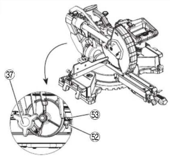
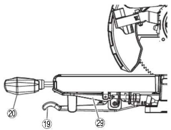
6. Installing the dust bag and vise (Fig. 1)
Install the dust bag onto the dust port on the miter saw. Fit the connecting tube of dust bag and the dust port together.
To empty the dust bag, pull out the dust bag assembly from dust port. Open zipper on underside of bag and empty into waste container. Check frequently and empty the dust bag before it gets full.
NOTE
The dust bag should be angled toward the right side of the saw for best results. This will also avoid any interference during the saw operation.
CAUTION
Empty the dust bag frequently to prevent the duct and the lower guard from becoming clogged. Sawdust will accumulate more quickly than normal during bevel cutting.
WARNING
Do not use this saw to cut and/or sand metals. the hot chips or sparks may ignite saw dust from the bag material.
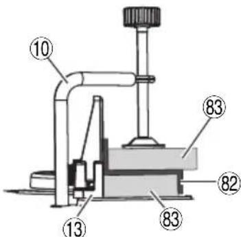
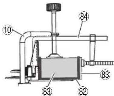
(Attach the vise assembly as shown in Fig. 1 and Fig. 28.)
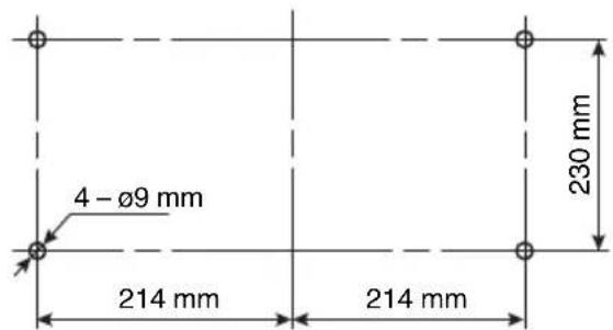
7. Installation (Fig. 3)
Ensure that the machine is always fixed to bench.
Attach the power tool to a level, horizontal work bench.
Select 8 mm diameter bolts suitable in length for the thickness of the work bench.
Bolt length should be at least 40 mm plus the thickness of the work bench.
For example, use 8 mm × 65 mm bolts for a 25 mm thick work bench.
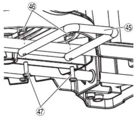
8. Installing the holder (Fig. 4)
The holder attached to the rear of the base helps stabilize the power tool.
Align the holder with the two holes under the rear of the base, and tighten two screws with a Philip screwdriver.
9. Check the lower guard for proper operation
Lower guard is designed to protect the operator from coming into contact with the saw blade during operation of the tool.
Always check that the lower guard moves smoothly after releasing the blade guard locking lever, and covers the saw blade properly.
WARNING
NEVER OPERATE THE POWER TOOL if the lower guard does not function smoothly.
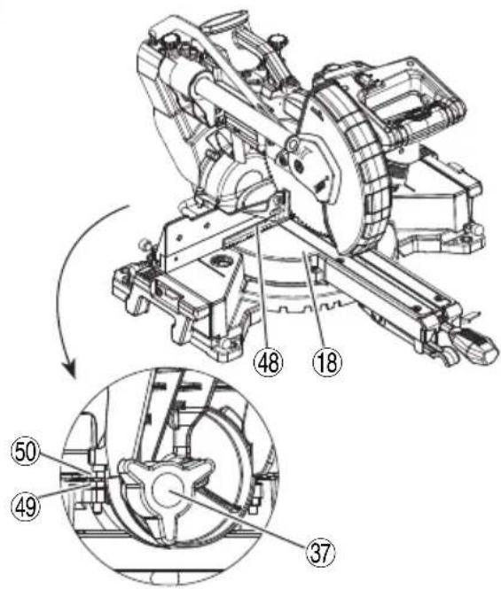
10. 90° (0°) Bevel adjustment (Fig. 5)
WARNING
To ensure accurate cuts, alignment should be checked and adjustments made prior to use.
(1) Loosen bevel lock knob and tilt the cutting arm completely to the right. Tighten the bevel lock knob.
(2) Place a combination square on the miter table with the ruler against the table and the heel of the square against the saw blade as show in Fig. 5.
(3) If the blade is not 90^ square with the miter table, loosen the bevel lock knob, tilt the cutting head to the left, loosen the lock nut on the bevel angle adjustment bolt and use a 10 mm spanner to adjust the bevel angle adjustment bolt depth in or out to increase or decrease the bevel angle.
(4) Tilt the cutting arm back to the right at 90^ bevel and recheck for alignment.
(5) Repeat steps 1 through 4 if further adjustment is needed.
(6) Tighten bevel lock knob and lock nut when alignment is achieved.
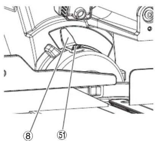
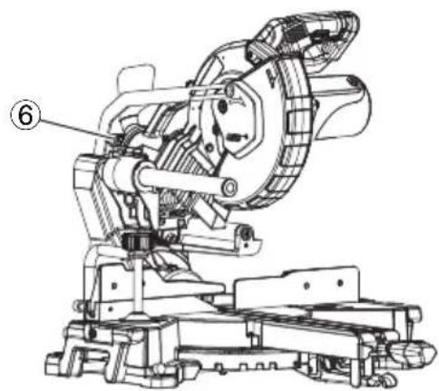
11. 90° Bevel pointer adjustment (Fig. 6)
(1) When the blade is exactly 90^ (0^) to the table, loosen the bevel pointer screw using a #2 Phillips screwdriver.
(2) Adjust bevel pointer to the "0" mark on the bevel scale and retighten the screw.
12. 45° Left bevel adjustment (Fig. 7)
(1) Loosen the bevel lock knob and tilt the cutting head completely to the left.
(2) Using a combination square, check to see if the blade is 45^ to the table.
(3) If the blade is not at 45^ to the miter table, tilt the cutting arm to the right, loosen the lock nut and use a 10 mm spanner to adjust the stop bolt depth in or out to increase or decrease the bevel angle.
(4) Tilt the cutting arm to the left to 45^ bevel and recheck for alignment.
(5) Repeat steps 1 through 4 until the blade at 45^ to the miter table.
(6) Tighten bevel lock knob and lock nut when alignment is achieved.
13. Miter angle adjustment
The slide compound miter saw scale can be easily read, showing miter angles from 0^ to 48^ to the left and right. The miter saw table has nine of the most common angle settings with positive stops at 0^ , 15^ , 22.5^ , 31.6^ , and 45^ . These positive stops position the blade at the desired angle quickly and accurately. Follow the process below for quickest and most accurate adjustments.
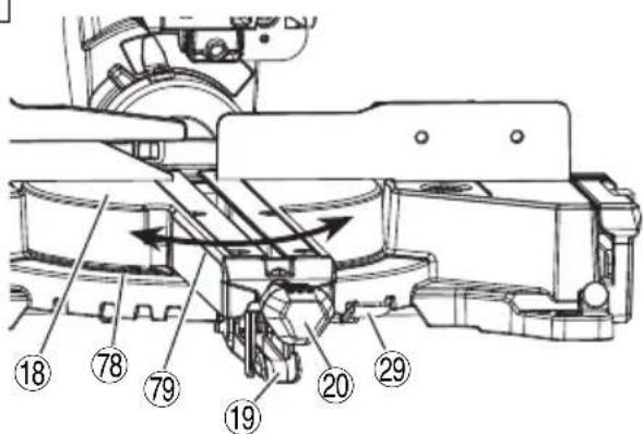
Adjusting miter angles: (Fig. 8)
(1) Lift up the quick-cam locking lever to unlock the table.
(2) Move the table while lifting up on the positive stop locking lever to align the pointer to the desired degree measurement.
(3) Lock the table into position by pressing down the quick-cam locking lever.
Miter pointer adjustment:
(1) Move the table to the 0^ positive stop.
(2) Loosen the screw that holds the miter pointer with a Phillips screwdriver.
(3) Adjust the pointer to the 0^ mark and retighten the screw.
14. Adjusting cutting depth
The maximum depth travel of the cutting head was set at the factory.
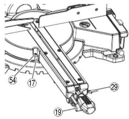
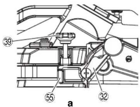
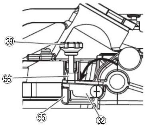
(1) Setting the maximum width travel of the cutting head, follow the below steps: (Fig. 9-a)
Turn the stop knob counterclockwise until the stop knob is not protruding out of the stop seat while moving the cutting head upward.
Rotate the anchor plate clockwise.
Recheck the blade depth by moving the cutting head front to back through the full motion of a typical cut along the control arm.
(2) Setting the maximum height travel of the cutting head, follow the below steps: (Fig. 9-b)
Turn the stop knob counterclockwise until the stop knob is not protruding out of the stop seat while moving the cutting head upward.
Rotate the anchor plate counterclockwise to touch the stop block.
Make sure the stop seat touches the anchor plate completely.
15. Setting the cutting depth (Fig. 9-b)
The depth of cut can be preset for even and repetitive shallow cuts.
(1) Adjust the cutting head down until the teeth of the blade are at the desired depth.
(2) While holding the upper arm in that position, turn the stop knob until it touches the anchor plate.
(3) Recheck the blade depth by moving the cutting head front to back through the full motion of a typical cut along the control arm.
NOTE
If the anchor plate becomes loose, it can interfere with raising and lowering the cutting head. The anchor plate must be tightened in horizontal position as shown in Fig. 9-b.
PRIOR TO CUTTING
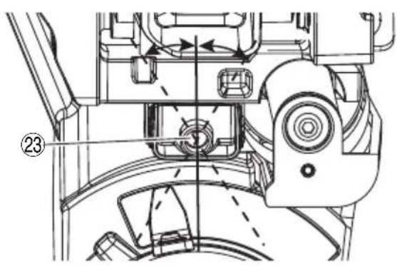
1. Positioning the table insert
Table inserts are installed on the turntable. When shipping the tool from the factory, the table inserts are so fi xed that the saw blade does not contact them. The burr of the bottom surface of the workpiece is remarkably reduced, if the table insert is fi xed so that the gap between the side surface of the table insert and the saw blade will be minimum. Before using the tool, eliminate this gap in accordance with the following procedure.
(1) Right angle cutting
Loosen the three 4 mm machine screws, then secure the left side table insert and temporarily tighten the 4 mm machine screws of both ends. Then fix a workpiece (about 200 mm wide) with the vise assembly and cut it off. After aligning the cutting surface with the edge of the table insert, securely tighten the 4 mm machine screws of both ends. Remove the workpiece and securely tighten the 4 mm center machine screw. Adjust the right hand table insert in the same way.
(2) Left bevel angle cutting
Adjust the table insert in the manner shown in Fig. 10-b following the same procedure for right angle cutting.
CAUTION
After adjusting the table insert for right angle cutting, the table insert will be cut to some extent if it is used for bevel angle cutting.
When bevel cutting operation is required, adjust the table insert for bevel angle cutting.
2. Use of sub fence
WARNING
The sub fence must be extended when making any left angle bevel cut. Failure to extend the sub fence will not allow enough space for the blade to pass through which could result in serious injury. At extreme miter or bevel angles the saw blade may also contact the fence.
This power tool is equipped with a sub fence.
In the case of direct angle cutting use the sub fence. Then, you can realize stable cutting of the material with a wide back face.
When left angle cutting, loosen the lock knob, then slide the sub fence outward, as shown in Fig. 11.
NOTE
When transporting the saw, always secure the sub fence in the collapsed position and lock it.
3. Securing the workpiece
WARNING
Always clamp or vise to secure the workpiece to the fence; otherwise the workpiece might be thrust from the table and cause bodily harm.
4. Slide carriage system (Fig. 12)
WARNING
To reduce the risk of injury, return slide carriage to the full rear position after each crosscut operation.
For chop cutting operations on small workpieces, slide the cutting head assembly completely toward the rear of the unit and tighten the slide securing knob.
To cut wide boards up to 305 mm, the slide securing knob must be loosened to allow the cutting head slide freely.
5. Quick-cam locking lever operation (Fig. 13)
If miter angles required are NOT one of the nine positive stops, the miter table can be locked at any angle between these positive stops by using the quick-cam locking lever.
Unlock the miter table by lifting up on the quick-cam locking lever. While holding the positive stop locking lever up, grasp the miter handle and move the table left or right to the desired angle. Release the positive stop locking lever. Press down on the quick-cam locking lever until it locks the table in place.
6. The laser guide
WARNING
- For your own safety, never connect the plug to power source outlet until the adjustment steps are complete and you have read and understood the safety and operational instructions.
- Your tool is equipped with a laser guide using a Class 1M laser guide. The laser guide allows you to preview the saw blade path on the workpiece to be cut before starting the miter saw. The saw must be connected to the power source and the laser on/off switch must be turned on for the laser line to show.
(1) Avoid direct eye contact (Fig. 14)
WARNING
* AVOID EXPOSURE
Laser radiation is emitted from this aperture.
CAUTION
● Use of controls or adjustments or performance of procedures may result in hazardous radiation exposure.
● The use of optical instruments with this product will increase eye hazard.
WARNING
Do not attempt to repair or disassemble the laser. If unqualifi ed persons attempt to repair this laser product, serious injury may result. Any repair required on this laser product should be performed by a qualifi ed service dealer.
English
(2) Checking laser line alignment (Fig. 15)
(a) Set the saw to a 0° miter and 0° bevel setting.
(b) Use a combination square to mark a 90^ angled running across the top of a board. This line will serve as the pattern line to adjust the laser. Place the board on the saw table.
(c) Carefully lower the saw head down to align the saw blade with the pattern line. Position the saw blade to the left, side of the "pattern line" depending on your preference for the laser line location. Lock the board in place with the hold-down clamp.
(d) With the saw plugged in, turn on the laser guide. Your saw has been preset with the laser line to the left side of the blade.
(e) Lower saw blade to pattern line and if blade is not flush with the pattern line, adjust as follow the instructions listed below under “Adjusting the angle of the laser line” paragraph and “Aligning the laser line” paragraph.
(3) Adjusting the angle of the laser line (Fig. 16, 17)
(a) After sliding the motor head forward, remove two rivets on two sides of the laser housing and take the laser housing off to reveal the laser marker. (Fig. 16)
(b) Turn the laser marker in the desired direction to adjust the laser angle. (Fig. 17)
NOTE
Do not adjust the laser more than 14 turn in either direction as this may damage the laser.
(4) Aligning the laser line. (Fig. 16, 18)
(a) Loosen only 12 turn at a time the four set screws. (Fig. 18)
(b) Adjust laser marker by turning the left side set screws clockwise to shift the laser line to the right. To shift the laser line to the left, turn the right side set screws 12 turn at a time.
(c) Once alignment of the laser is achieved, tighten only 12 turn at a time the four set screws.
(d) After finishing the laser adjustment, replace the laser housing on the laser marker and then tighten the two rivets. (Fig. 16)
PRACTICAL APPLICATIONS
WARNING
To avoid personal injury, never remove or place a workpiece on the table while the tool is being operated.
Never place your limbs inside of the line next to warning sign while the tool is being operated (see Fig. 19). This may cause hazardous conditions.
CAUTION
- It is dangerous to remove or install the workpiece while the saw blade is turning.
○ When sawing, clean off the shavings from the turntable.
☐ If the shavings accumulate too much, the saw blade from the cutting material will be exposed. Never subject your hand or anything else to go near the exposed blade.
NOTE
Prior to operating the switch, make sure to check the stability of the tool by setting the angle and turn to conduct a trial cutting run without using a workpiece.
1. Switch operation (Fig. 20)
(1) Turning the saw on
This miter saw is equipped with a trigger switch. Squeeze the trigger switch to turn the miter saw ON. Release the trigger switch to turn the saw OFF.
(2) Turning the laser guide on
Press the laser switch to turn it ON, and press again to turn it OFF.
WARNING
Make the ON/OFF switch childproof. Insert a padlock, or chain with padlock, through the hole in the trigger and lock the tool's switch, preventing children and other unqualified users from turning the machine on.
2. Using the Vise Assembly (Standard accessory)
(1) The vise assembly can be mounted on the base.
(2) Turn the vise lock knob and securely fix the vise assembly.
(3) Turn the upper knob and securely fix the workpiece in position (Fig. 21).
NOTE
When using the vise, make sure that the tool is free of any excessive contact when the unit is swing or slide.
WARNING
Always fi rmly clamp or vise to secure the workpiece to the fence; otherwise the workpiece might be thrust from the table and cause bodily harm.
3. Cutting Operation
(1) As shown in Fig. 22 the width of the saw blade is the width of the cut. Therefore, slide the workpiece to the right (viewed from the operator's position) when length ⑤ is desired, or to the left when length ⑧ is desired.
If a laser marker is used, align the laser line with the left side of the saw blade, and then align the ink line with the laser line.
(2) Once the saw blade reaches maximum speed, push the handle down carefully until the saw blade approaches the workpiece.
(3) Once the saw blade contacts the workpiece, push the handle down gradually to cut into the workpiece.
(4) After cutting the workpiece to the desired depth, turn the power tool OFF and let the saw blade stop completely before raising the handle from the workpiece to return it to the full retract position.
CAUTION
Increased pressure on the handle will not increase the cutting speed. On the contrary, too much pressure may result in overload of the motor and/or decreased cutting efficiency.
WARNING
- Confirm that the trigger switch is turned OFF and the power plug has been removed from the receptacle whenever the tool is not in use.
● Always turn the power off and let the saw blade stop completely before raising the handle from the workpiece. If the handle is raised while the saw blade is still rotating, the cut-off piece may become jammed against the saw blade causing fragments to scatter about dangerously. - Every time one cutting or deep-cutting operation is finished, turn the trigger switch off, and check that the saw blade has stopped. Then raise the handle, and return it to the full retract position.
- Be absolutely sure to remove the cut material from the top of the turntable, and then proceed to the next step.
- Continued cutting operation can result in overload of the motor. Touch the motor and if it's hot, stop your cutting operation at once and rest for 10 minutes or so, and then restart your cutting operation.
4. Cutting wide workpieces (Slide cutting)
(1) Workpieces up to 65 mm high and 280 mm wide:
loosen the slide securing knob (see Fig. 1), grip the handle and slide the saw blade forward.
Then press down on the handle and slide the saw blade backward to cut the workpiece as indicated in Fig. 23. This facilitates cutting of workpieces of up to 65 mm in height and 280 mm in width.
(2) Workpieces up to 54 mm high and 305 mm wide:
Workpieces of up to 54 mm in height and up to 305 mm in width can be cut in the same manner as described in paragraph 4-(1) above on page 34.
CAUTION
- If the handle is pressed down with excessive or lateral force, the saw blade may vibrate during the cutting operation and cause unwanted cutting marks on the workpiece, thus reducing the quality of the cut.
Accordingly, press the handle down gently and carefully.
- In slide cutting, gently push the handle back (rearwards) in a single, smooth operation.
Stopping the handle movement during the cut will cause unwanted cutting marks on the workpiece.
WARNING
- For slide cutting, follow the procedures indicated above in Fig. 23.
Forward slide cutting (toward the operator) is very dangerous because the saw blade could kick upward from the workpiece. Therefore, always slide the handle away from the operator.
● Always return the carriage to the full rear position after each crosscut operation in order to reduce the risk of injury.
● Never put your hand on the miter handle during the cutting operation because the saw blade comes close to the miter handle when the motor head is lowered.
5. Bevel cutting procedures
WARNING
The sub fence must be extended when making any bevel cut. Failure to extend the sub fence will not allow enough space for the blade to pass through which could result in serious injury. At extreme miter or bevel angles the saw blade may also contact the fence.
(1) When a bevel cut is required, loosen the bevel lock knob by turning it clockwise. (Fig. 24)
(2) Tilt the cutting head to the desired angle, as shown on the bevel scale.
(3) The blade can be positioned at any angle, from a 90^ straight cut ( 0^ on the scale) to a 45^ . Tighten the bevel lock knob to lock the cutting head in position. Positive stops are provided at 0^ and 45^ .
(4) Turn the laser guide on and position the workpiece on the table for pre-alignment of your cut.
WARNING
When the workpiece is secured on the left or right side of the blade, the short cut-off portion will come to rest on the right or left side of the saw blade. Always turn the power off and let the saw blade stop completely before raising the handle from the workpiece.
If the handle is raised while the saw blade is still rotating, the cut-off piece may become jammed against the saw blade causing fragments to scatter about dangerously.
When stopping the bevel cutting operation halfway, start cutting after pulling back the motor head to the initial position.
Starting from halfway, without pulling back, causes the lower guard to be caught in the cutting groove of the workpiece and to contact the saw blade.
CAUTION
- If not tightened firmly enough the motor head might suddenly move or slip, causing injuries. Be sure to tighten the motor head section enough so it will not move.
● Always check that the bevel lock knob is secured and the motor head is clamped. If you attempt angle cutting without clamping the motor head, then the motor head might shift unexpectedly causing injuries.
6. Miter cutting procedures (Fig. 25)
(1) Unlock the miter table by lifting up on the quick-cam locking lever.
(2) While raising the positive stop locking lever up, grasp the miter handle and rotate the table left or right to the desired angle.
(3) Release the positive stop locking lever and set the table at the desired angle, making sure the lever snaps into place.
(4) Once the desired miter angle is achieved, press down on the quick-cam locking lever to secure the table into position.
(5) If the desired miter angle is NOT one of the nine positive stops noted above, simply lock the table at the desired angle by pressing down on the quick-cam locking lever.
(6) Turn the laser guide on and position the workpiece on the table for pre-alignment of your cut.
CAUTION
Always check that the miter handle is secured and the turntable is clamped.
If you attempt angle cutting without clamping the turntable, then the turntable might shift unexpectedly causing injuries.
NOTE
○ Positive stops are provided at the right and left of the 0^ center setting, at 15^ , 22.5^ , 31.6^ and 45^ settings.
Check that the miter scale and the tip of the indicator are properly aligned.
Operation of the saw with the miter scale and indicator out of alignment will result in poor cutting precision.
7. Compound cutting procedures
Compound cutting can be performed by following the instructions in 4 to 6 above. For maximum dimensions for compound cutting, refer to “SPECIFICATIONS” table on page 31.
CAUTION
Always secure the workpiece with the right or left hand and cut it by sliding the round portion of the saw backwards with the other hand.
It is very dangerous to rotate the turntable to the left during compound cutting because the saw blade may come into contact with the hand that is securing the workpiece.
In case of compound cutting (angle + bevel) by left bevel, extend the sub fence fully before cutting operation.
Please confirm that sub fence does not interfere with other parts before attempting compound cutting.
8. Groove cutting procedures
Grooves in the workpiece can be cut as indicated in Fig. 26 by adjusting the stop knob.
Cutting depth adjustment procedure:
(1) Turn the anchor plate on the direction shown in Fig. 27.
Lower the motor head, and turn the stop knob by hand. (where the head of the stop knob contacts the anchor plate.)
(2) Adjust to the desired cutting depth by setting the distance between the saw blade and the surface of the turntable (see ⑥ in Fig. 27).
NOTE
When cutting a single groove at either end of the workpiece, remove the unneeded portion with a chisel.
9. Cutting easily-deformed materials, such as aluminum sash
Materials such as aluminum sash can easily deform when tightened too much in a vise assembly. This will cause inefficient cutting and possible overload of the motor.
When cutting such materials, use a wood plate to protect the workpiece as shown in Fig. 28-a. Set the wood plate near the cutting section.
When cutting aluminum materials, coat the saw blade with cutting oil (non-combustible) to achieve smooth cutting and a fine finish.
In addition, in case of a U-shaped workpiece, use the wood plate as shown in Fig. 28-b to ensure stability in the lateral direction, and clamp it near the cutting section of the workpiece and tighten it using both the vise assembly and the clamp available in the market.
SAW BLADE MOUNTING AND DISMOUNTING
WARNING
● To prevent an accident or personal injury, always turn off the trigger switch and disconnect the power plug from the receptacle before removing or installing a saw blade.
If cutting work is done in a state where the 8 mm bolt is not sufficiently tightened, the 8 mm bolt can get loose, the blade can come off, and the lower guard can get damaged, resulting in injuries.
Also, check that the 8 mm bolts are properly tightened before plugging the power plug into the receptacle.
- If the 8 mm bolts are attached or detached using tools other than the 13 mm wrench (standard accessory), excessive or improperly tightening occurs, resulting in injury.
1. Dismounting the blade (Fig. 29-a, Fig. 29-b, Fig. 29-c and Fig. 29-d)
(1) Unplug the power cord from the outlet.
(2) Raise the cutting head to the upright position and slide the cutting head completely toward the rear of the unit and tighten the slide securing knob.
(3) Push slightly on the blade guard locking lever and then raise the lower guard to the uppermost position.
(4) While holding the lower guard, remove the cover plate screw with a Phillips screwdriver.
(5) Rotate the cover plate to expose the 8 mm bolt.
(6) Place the blade end spanner over the 8 mm bolt.
(7) Locate the spindle lock on the motor.
(8) Press the spindle lock, holding it in firmly while turning the blade clockwise. The spindle lock will then engage and lock the arbor. Continue to hold the spindle lock, while turning the spanner clockwise to loosen the 8 mm bolt.
(9) Remove the 8 mm bolt, washer (B) and the blade. Do not remove the washer (A).
NOTE
☐ If the spindle lock cannot be easily pressed in to lock the spindle, turn the 8 mm bolt with 13 mm wrench (standard accessory) while applying pressure on the spindle lock.
The saw blade spindle is locked when the spindle lock is pressed inward.
○ Pay attention to the pieces removed, noting their position and direction they face. Wipe the washer (B) clean from any sawdust before installing a new blade.
WARNING
When mounting the saw blade, confi rm that the rotation indicator mark on the saw blade and the rotation direction of the lower guard (see Fig. 1) are properly matched.
CAUTION
- Confirm that the spindle lock has returned to the retract position after installing or removing the saw blade.
● Tighten the 8 mm bolt so it does not come loose during operation.
Confir rm the 8 mm bolt has been properly tightened before the power tool is started.
2. Mounting the saw blade
WARNING
Unplug the miter saw before changing/installing the blade.
(1) Install a 216 mm blade with arbor, making sure the rotation arrow on the blade matches the clockwise rotation arrow on the lower guard, and the blade teeth are pointing downward.
(2) Place washer (B) against the blade. Thread the 8 mm bolt on arbor in a counterclockwise direction.
NOTE
Make sure the flats of the washers are engaged with the flats on the arbor shaft. Also, the flat side of the washer must be placed against the blade.
(3) Place the blade spanner on the 8 mm bolt.
(4) Press the spindle lock, holding it in firmly while turning the blade counterclockwise. When it engages, continue to press the spindle lock in, while tightening the 8 mm bolt securely.
(5) Rotate the cover plate back to its original position until the slot in the cover plate engages with the hole of cover plate screw.
While holding the lower guard at the uppermost position, tighten the cover plate screw with a Phillips screwdriver.
(6) Lower the lower guard and verify that operation of the guard and blade guard locking lever do not bind or stick.
(7) Be sure the spindle lock is released so the blade turns freely.
CAUTION
Never attempt to install saw blades larger than 216 mm in diameter.
Always install saw blades that are 216 mm in diameter or less.
MAINTENANCE AND INSPECTION
WARNING
To avoid an accident or personal injury, always confirm that the trigger switch is turned OFF before performing any maintenance or inspection of this tool.
Report to qualified person as soon as possible, if you discover the fault of machine including guards or blade saw.
1. Inspecting the saw blade
Always replace the saw blade immediately upon the first sign of deterioration or damage.
A damaged saw blade can cause personal injury and a worn saw blade can cause ineff ective operation and possible overload to the motor.
CAUTION
Never use a dull saw blade. When a saw blade is dull, its resistance to the hand pressure applied by the tool handle tends to increase, making it unsafe to operate the power tool.
2. Inspecting the mounting screws
Regularly inspect all mounting screws and ensure that they are properly tightened. Should any of the screws be loose, re-tighten them immediately. Failure to do so could result in serious hazard.
3. Inspecting the carbon brushes (Fig. 30)
Replace both carbon brushes when either has less than 6 mm length of carbon remaining, or if the spring or wire is damaged or burned. To inspect or replace brushes, fi rst unplug the saw. Then remove the brush cap on the side of the motor. Remove the cap cautiously, because it is springloaded. Then pull out the brush and replace.
Replace for the other side. To reassemble reverse the procedure. The ears on the metal end of the assembly go in the same hole the carbon part fits into. Tighten the cap snugly, but do not overtighten.
NOTE
To reinstall the same brushes, first make sure the brushes go back in the way they came out. This will avoid a break-in period that reduces motor performance and increases wear.
4. Maintenance of the motor
The motor unit winding is the very “heart” of the power tool. Exercise due care to ensure the winding does not become damaged and/or wet with oil or water.
5. Replacing supply cord
If the supply cord of Tool is damaged, the Tool must be returned to HiKOKI Authorized Service Center for the cord to be replaced.
6. Inspecting the lower guard for proper operation
Before each use of the tool, test the lower guard (Fig. 1) to assure that it is in good condition and that it moves smoothly.
Never use the tool unless the lower guard operates properly and it is in good mechanical condition.
7. Storage
After operation of the tool has been completed, check that the following has been performed:
(1) Trigger switch is in OFF position,
(2) Power plug has been removed from the receptacle. When the tool is not in use, keep it stored in a dry place out of the reach of children.
CAUTION
In the operation and maintenance of power tools, the safety regulations and standards prescribed in each country must be observed.
8. Lubrication
Lubricate the following sliding surfaces once a month to keep the power tool in good operating condition for a long time.
Use of machine oil is recommended.
Oil supply points:
* Rotary portion of hinge
* Rotary portion of holder (A)
* Rotary portion of vise assembly
9. Cleaning (Fig. 31)
Clean the machine, duct and lower guard by blowing with dry air from an air gun or other tool.
Periodically remove chips, dust and other waste material from the surface of the power tool, especially from the inside of the lower guard with a damp, soapy cloth. To avoid a malfunction of the motor, protect it from contact with oil or water.
If the laser line becomes invisible due to chips and the like adhered onto the window of the laser marker's light-emitting section, wipe and clean the window with a dry cloth or a soft cloth moistened with soapy water, etc.
SELECTING ACCESSORIES
The accessories of this machine are listed on page 302.
CAUTION
Repair, modification and inspection of HiKOKI Power Tools must be carried out by a HiKOKI Authorized Service Center.
Especially laser device should be maintained by the authorized agent by laser manufacturer.
Always assign the repair of laser device to HiKOKI Authorized Service Center.
In the operation and maintenance of power tools, the safety regulations and standards prescribed in each country must be observed.
GUARANTEE
We guarantee HiKOKI Power Tools in accordance with statutory/country specific regulation. This guarantee does not cover defects or damage due to misuse, abuse, or normal wear and tear. In case of complaint, please send the Power Tool, undismantled, with the GUARANTEE CERTIFICATE found at the end of this Handling instruction, to a HiKOKI Authorized Service Center.
NOTE
Due to HiKOKI's continuing program of research and development the specifications herein are subject to change without prior notice.
Information concerning airborne noise
The measured values were determined according to EN62841 and declared in accordance with ISO 4871.
Measured A-weighted sound power level: 107 dB (A). Measured A-weighted sound pressure level: 94 dB (A). Uncertainty K: 3 dB (A).
Wear hearing protection.
The declared noise emission value has been measured in accordance with a standard test method and may be used for comparing one tool with another;
It may also be used in a preliminary assessment of exposure. WARNING
☐ The noise emissions during actual use of the power tool can differ from the declared values depending on the ways in which the tool is used especially what kind of workpiece is processed.
- Identify safety measures to protect the operator that are based on an estimation of exposure in the actual conditions of use (taking account of all parts of the operating cycle such as the times when the tool is switched off and when it is running idle in addition to the trigger time).
Information for power supply system to be used with electric tools provided with rated voltage 230 V\~
Switching operations of electric apparatus cause voltage fluctuations.
The operation of this electric tool under unfavorable mains conditions can have adverse effects to the operation of other electric apparatus.
With a mains impedance equal or less than 0.29 Ohms there will probably be no negative effects.
Usually, the maximum permissible mains impedance will not be exceeded when the branch to the power outlet is fed from a junction box with a service capacity of 25 ampere or higher.
In case of power failure, or when the power plug is pulled out, immediately return the switch to OFF position. This prevents an uncontrolled restart.
TROUBLESHOOTING
Use the inspections in the table below if the tool does not operate normally. If this does not remedy the problem, consult your dealer or the HiKOKI Authorized Service Center.
Power tool
| Symptom Possible | cause Remedy | ||
| Tool doesn’t run Trigger switch | ch is in OFF position Turn on the switch. | ||
| The power cord is not plugged in properly. Plug the power cord correctly. | |||
| Tool suddenly stopped Tool | was overburdened. Get rid of the problem causing the overburden. | ||
| Cannot be tilted The clamp lever | has not been loosened. Loosen the clamp lever and then tilt the tool. After adjusting the loosened component, make sure to tighten it once again. | ||
| Sawblade is dull The sawblade | de is worn down or missing teeth. | Exchange with a new sawblade. | |
| Bolt is loose. Tighten the bolt. | |||
| The sawblade has been installed in reverse. Install the sawblade in the correct direction. | |||
| Cannot cut with precision The operation parts of the tool are not fully fixed. | Fully fix the clamp lever and bevel lock knob. | ||
| Material cannot be fixed in the correct position. | Remove any foreign material from the fence or turntable. | ||
| In some cases, proper position cannot be fixed due to a curve in the material. Try to fix a flat surface with the fence or turntable. | |||
| Motor head cannot be lowered | Blade guard locking lever is not released. Release the blade guard locking lever and then lower the motor head. | ||
ALLGEMEINE
APPLICATIONS PRATIQUES
AVERTISSEMENT
7. Prosedyre for kompoundsaging
VEDLIKEHOLD OG INSPEKSJON
ADVARSEL
natural_image
Technical line drawing of a mechanical component with ribbed texture (no text or symbols)375487
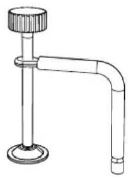
natural_image
Line drawing of a laboratory apparatus with a flanged neck and curved tube (no text or symbols)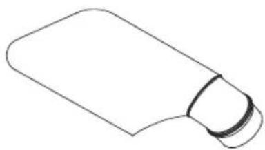
natural_image
Simple line drawing of a rectangular object with a curved top and base (no text or symbols)373912
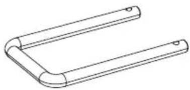
natural_image
Line drawing of a U-shaped metal bracket with two notches (no text or symbols)375505375531
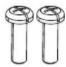
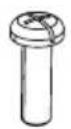
375488
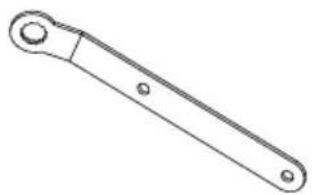
natural_image
Line drawing of a mechanical wrench (no text or symbols)372446372508
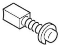
natural_image
Simple line drawing of a bolt and nut (no text or symbols)230V: 375618
110V: 375563
| English Dansk Română | ||||
| GUARANTEE CERTIFICATE1 Model No.2 Serial No.3 Date of Purchase4 Customer Name and Address5 Dealer Name and Address(Please stamp dealer name and address) | GARANTIBEVIS1 Modelnummer2 Serienummer3 Købsdato4 Kundes navn og adresse5 Forhandlers navn og adresse(Indsæt stempel med forhandlers navn og adresse) | CERTIFICAT DE GARANTIE1 Model nr.2 Nr. de serie3 Data cumpäräri4 Numele și adresa clientului5 Numele și adresa distribuitorului(Vå rugâm aplicați štampila cu numele și adresa distribuitorului) | ||
| Deutsch Norsk Slovenščina | ||||
| GARANTIESCHEIN1 Modell-Nr.2 Serien-Nr.3 Kaufdatum4 Name und Anschrift des Kunden5 Name und Anschrift des Händlers(Bitte mit Namen und Anschrift des Handlers abstempeln) | GARANTISERTIFIKAT1 Modellnr.2 Serienr.3 Kjøpsdato4 Kundens navn og adresse5 Forhandlerens navn og adresse(Vennligst stemple forhandlerens navn og adresse) | GARANCIJSKO POTRDILO1 Št. modela2 Serijska št.3 Datum nakupa4 Ime in naslov kupca5 Ime in naslov prodajalca(Prosimo vtsnite žig z imenom in naslovom prodajalca) | ||
| Français Suomi Slovenčina | ||||
| CERTIFICAT DE GARANTIE1 No. de modèle2 No de série3 Date d'achat4 Nom et adresse du client5 Nom et adresse du revendeur(Cachet portant le nom et l'adresse du revendeur) | TAKUUTODISTUS1 Malli nro2 Sarja nro3 Ostopäivämäärä4 Asiakkaan nimi ja osoite5 Myyjän nimi ja osoite(Leimaa myyjän nimi ja osoite) | ZÁRUČNÝ LISTA1 Č. modelu2 Sériové č.3 Dátum zakúpenia4 Meno a adresa zákaznika5 Názov a adresa predajcu(Pečiatka s názvom a adresou predajcu) | ||
| Italiano Ελληνικά Български | ||||
| CERTIFICATO DI GARANZIA1 Modello2 N° di serie3 Data di acquisto4 Nome e indirizzo dell'acquirente5 Nome e indirizzo del rivenditore(Si prega di apporre il timbro con questi dati) | ПІЗТОПОІНТІКО ЕГГУНЄНЄ1 Ap. Movтėlou2 Aŭђων Ap.3 Нμερομηνία αγοράς4 ́Овома кай бієўθυνση πελάτη5 ́Овома кай бієўθυνση μεταπωλητή(Παρακαλούμε να χρησιμοποιθεί σφραγίδα) | ГАРАНЦИОНЕН СЕРТИФИКАТ1 Модел No2 Сериен No3 Дата за закупуване4 Име и адрес на клиента5 Име и адрес на търговеца(Моля, отпечатайте името и адрес на дильра) | ||
| Nederlands Polski Srpski | ||||
| GARANTIEBEWIJS1 Modelnummer2 Seriennummer3 Datum van aankoop4 Naam en adres van de gebruiker5 Naam en adres van de handelaar(Stempel a.u.b. naam en adres vande de handelaar) | GWARANCJA1 Model2 Numer seryjny3 Data zakupu4 Nazwa klienta i adres5 Nazwa dealera i adres(Pieczęć punktu sprzedaży) | GARANTNI SERTIFIKAT1 Br. modela.2 Serijski br.3 Datum kupovine4 Ime i adresa kupca5 Ime i adresa prodavca(Molimo da stavite pečat na ime i adresu trgovca) | ||
| Español Magyar Hrvatski | ||||
| CERTIFICADO DE GARANTÍA1 Número de modelo2 Número de serie3 Fecha de adquisición4 Nombre y dirección del cliente5 Nombre y dirección del distribuidor(Se ruega poner el sello del distribuidor con su nombre y dirección) | GARANCIA BIZONYLAT1 Tipusszám2 Sorozatszám3 A vásárlás dátuma4 A Vásárló neve és címe5 A Kereskedő neve és címe(Kárjük ide olhelyezni a Kereskedő nevének és címének pecsétjét) | JAMSTVENI CERTIFIKAT1 Br modela.2 Serijski br.3 Datum kupnje4 Ime i adresa kupca5 Ime i adresa trgovca(Molimo stavite pečat na ime i adresu trgovca) | ||
| Português Čeština | ||||
| CERTIFICADO DE GARANTIA1 Número do modelo2 Número do série3 Data de compra4 Nome e morada do cliente5 Nome e morada do distribuidor(Por favor, carímbe o nome e morada do distribuidor) | ZÁBUČNÍ LIST1 Model č.2 Série č.3 Datum nákupu4 Jméno a adresa zákazníka5 Jméno a adresa prodejce(Prosíme o razítko se jménem a adresou prodejce) | |||
| Svenska Türkçe | ||||
| GARANTICERTIFIKAT1 Modellnr2 Serienn3 Inköpsdatum4 Kundens namn och adress5 Försäljarens namn och adress(Stämpia försäljarens namn och adress) | GARANTI SERTÍFÍKASI1 Model No.2 Seri No.3 Satin Alma Tarihi4 Müşteri Adı ve Adresi5 Bayi Adı ve Adresi(Lütfen bayi adini ve adresini kaşe olarak basın) | |||
HiKOKI
| 1 | |
| 2 | |
| 3 | |
| 4 | |
| 5 |
Siemensring 34, 47877 willich, Germany
Tel: +49 2154 49930
Fax: +49 2154 499350
URL: http://www.hikoki-powertools.de
Hikoki Power Tools Netherlands B.V.
Brabanthaven 11, 3433 PJ Nieuwegein, The Netherlands
Tel: +31 30 6084040
Fax: +31 30 6067266
URL: http://www.hikoki-powertools.nl
Hikoki Power Tools (U.K.) Ltd.
Precedent Drive, Rooksley, Milton Keynes, MK 13, 8PJ,
United Kingdom
Tel: +44 1908 660663
Fax: +44 1908 606642
URL: http://www.hikoki-powertools.uk
Hikoki Power Tools France S.A.S.
Hikoki Power Tools Belgium N.V./S.A.
Koningin Astridlaan 51, B-1780 Wemmel, Belgium
Tel: +32 2 460 1720
Fax: +32 2 460 2542
URL http://www.hikoki-powertools.be
Hikoki Power Tools Italia S.p.A
Via Piave 35, 36077, Altavilla Vicentina (VI), Italy
Tel: +39 0444 548111
Fax: +39 0444 548110
URL: http://www.hikoki-powertools.it
Hikoki Power Tools Ibérica, S.A.
C/ Puigbarral, 26-28, Pol. Ind. Can Petit, 08227 Terrassa
(Barcelona), Spain
Tel: +34 93 735 6722
Fax: +34 93 735 7442
URL: http://www.hikoki-powertools.es
Kjeller Vest 7, N-2007 Kjeller, Norway
Tel: (+47) 6692 6600
Fax: (+47) 6692 6650
URL: http://www.hikoki-powertools.no
Hikoki Power Tools Sweden AB
Rotebergsvagen 2B SE-192 78 Sollentuna, Sweden
Tel: (+46) 8 598 999 00
Fax: (+46) 8 598 999 40
URL: http://www.hikoki-powertools.se
Hikoki Power Tools Denmark A/S
Lillebaeltsvej 90, 6715 Esbjerg N, Denmark
Tel: (+45) 75 14 32 00
Fax: (+45) 75 14 36 66
URL: http://www.hikoki-powertools.dk
Hikoki Power Tools Finland Oy
Tupalankatu 9, 15680 Lahti, Finland
Tel: (+358) 20 7431 530
Fax: (+358) 20 7431 531
URL: http://www.hikoki-powertools.fi
Hikoki Power Tools Hungary Kft.
Hikoki Power Tools Romania S.R.L.
Ring Road, No. 66, Mustang Traco Warehouses, Warehouse
No.1, Pantelimon City, 077145, Ilfov County, Romania