
CB12-ST2 - Saw HiKOKI - Free user manual and instructions
Find the device manual for free CB12-ST2 HiKOKI in PDF.

| Product Type | Band Saw Stand (stationary) |
| Brand | HiKOKI |
| Model | CB12-ST2 |
| Compatible Band Saw | HiKOKI CB3612DA (rotary band saw) |
| Max. Cutting Capacity (90°) | Round pipe Φ115 mm; Square pipe 100 mm x 100 mm |
| Max. Cutting Capacity (45°) | Round pipe Φ50 mm; Square pipe 50 mm x 50 mm |
| Weight | 14.5 kg (approx. 32 lbs) |
| Cutting Angles | 0° to 45° (adjustable) |
| Cutting Load Settings | 4 settings: Heavy, Medium, Light, Lightest |
| Vise Type | Quick-action with clutch |
| Includes | Contour table, slide cover, slide cover holder, butterfly bolt (5 mm), vise guide, hexagonal wrenches (4 mm & 8 mm), knob bolts, bolt washers |
| Safety Features | Switch lock, blade guard (optional slide cover), stopper bolt |
| Portability | Wheels and front handle for easy movement |
| Maintenance | Keep clean, check bolts and blade tension regularly |
| Repairability | User-replaceable parts: band saw blade, wrenches, hardware; service by qualified personnel |
Frequently Asked Questions - CB12-ST2 HiKOKI
User questions about CB12-ST2 HiKOKI
0 question about this device. Answer the ones you know or ask your own.
Ask a new question about this device
Download the instructions for your Saw in PDF format for free! Find your manual CB12-ST2 - HiKOKI and take your electronic device back in hand. On this page are published all the documents necessary for the use of your device. CB12-ST2 by HiKOKI.
USER MANUAL CB12-ST2 HiKOKI
natural_image
Technical line drawing of a mechanical clamp or fixture assembly (no text or symbols)BAND SAW STAND SAFETY WARNINGS
● Correctly install the band saw stand by following the instructions provided in the manual.
- In order to prevent accidents, when installing or removing the band saw stand, turn the switch of the rotary band saw off. If your band saw has a power cord, remove the power plug from the outlet. If your band saw is a cordless model, remove the battery from the main unit.
● After installing the band saw on the band saw stand, follow the instructions provided in the manual of the rotary band saw.
NAMES OF PARTS
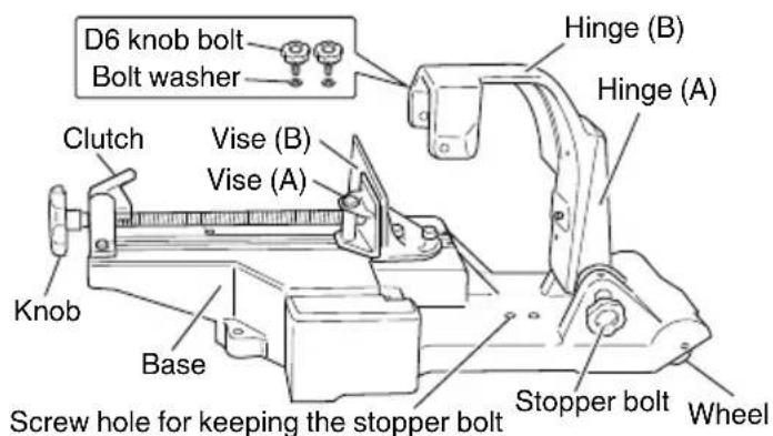
![[Opposite side] Spring Spring stopper Hexagonal wrenches (4 mm and 8 mm)](/content/2026/06/1221485/images/a24896b0293c52913343d04deb509c4ccbe5d5cb3fdb68eb0c24aef41c0d26e3.jpg)
Fig. 1
SYMBOLS
WARNING
The following show symbols used for the machine. Be sure that you understand their meaning before use.
| To reduce the risk of injury, user must read instruction manual. | |
| Warning |
STANDARD ACCESSORIES
Contour table Slide cover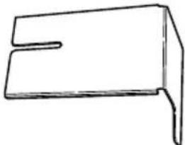 Used when carrying out contour cutting work. Used when carrying out contour cutting work. | 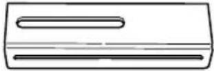 Used to prevent the band saw blade from being exposed during contour cutting work. Used to prevent the band saw blade from being exposed during contour cutting work. |
| One One | |
Slide cover holder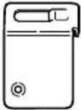 Used to install the slide cover and adjust its position during work. Used to install the slide cover and adjust its position during work. | Butterfly bolt(5 mm) Used to install the slide cover holder on the main unit. Used to install the slide cover holder on the main unit. |
| One One | |
Vise guide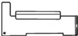 Used to adjust the angle of the band saw blade and cut thin or small diameter workpieces. Used to adjust the angle of the band saw blade and cut thin or small diameter workpieces. | Hexagonal wrench(4 mm)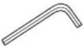 Used to adjust the lower limit position of the band saw blade. Used to adjust the lower limit position of the band saw blade. |
| One One | |
Hexagonal wrench (8 mm)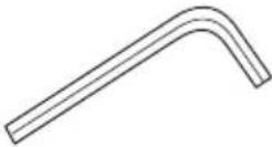 Used to move vise (B) and adjust the positions of the hinges. Used to move vise (B) and adjust the positions of the hinges. | Knob boltsBolt washers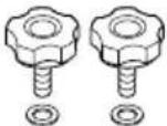 Used to install a band saw on the band saw stand. Used to install a band saw on the band saw stand. |
| One Two each |
APPLICATIONS
Band saw stand especially designed for stationary implementation of right-angle cutting, angle cutting, and contour cutting work, for use with the following HiKOKI band saw: CB3612DA
For details regarding the latest available band saw, check our general catalogue and other information.
SPECIFICATIONS
| Model CB12-ST2 | |||
| Max. cutting capacity* | 90° | Round pipe | Φ115 mm |
| Square pipe | Width 100 mm x Height 100 mm | ||
| 45° | Round pipe | Φ50 mm | |
| Square pipe | Width 50 mm x Height 50 mm | ||
| Weight 14.5 kg | |||
* Maximum cutting capacity possible when a rotary band saw is installed
HOW TO USE
1. Installing the band saw stand and switch holder
(1) Move the lever switch to the OFF position, and remove the battery from the main tool unit.
(2) When the stopper bolt is loosened, the hinges of the band saw stand will fall over backward (toward the wheels) due to the force of the spring.
While loosening the stopper bolt, hold the top of the hinges so that they do not fall over backward. (Fig. 2)
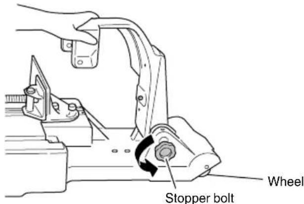
Fig. 2
(3) Align the hole in the side of pulley guard (A) with the D8 pin of hinge (A), and insert the D8 pin into the hole. (Fig. 3)
(4) One D6 knob bolt is provided on each of the front and rear sides of hinge (B). Only tighten the one on the rear side. (Fig. 3)
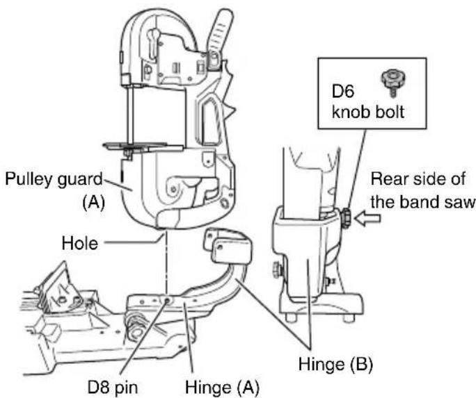
Fig. 3
NOTE
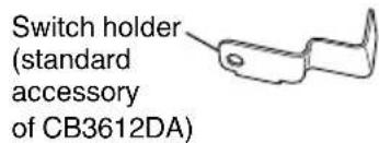
The switch holder needs to be installed in order to use the band saw installed on the stand.
(5) While pressing the switch lock, pull the switch and fit the switch holder into position.
This locks the switch in the ON position. (Fig. 4)
(6) Tighten the D6 knob bolt on the front side.
When the installation procedure has been correctly carried out, the switch lock is held in the pressed position. (Fig. 4)
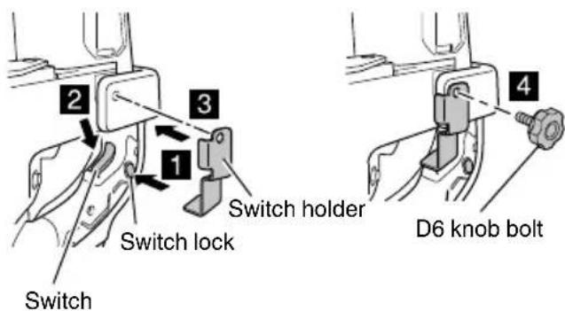
Fig. 4
English
(7) Check that the D6 knob bolt on the rear side is correctly tightened, and that the main tool unit is securely installed on the stand. (Fig. 5)
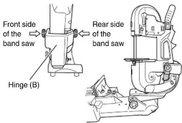
Fig. 5
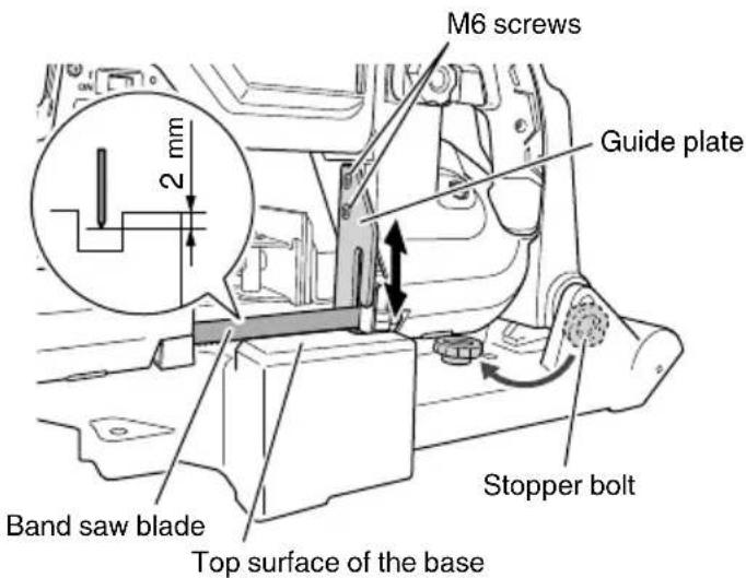
Fig. 7
2. Operating the switch
After installing the band saw on the stand, check that the switch can be correctly operated.
(1) Check that the band saw stand is correctly secured, and that the lever switch is in the OFF position. (Fig. 6)
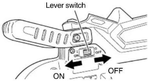
Fig. 6
(2) Install the battery on the main tool unit.
(3) Check that the band saw blade is not touching anything, then turn the lever switch ON and OFF to check that the band saw operates correctly.
NOTE
The lever switch does not function unless the switch is held in the ON position using the switch holder.
3. Adjusting the lower limit position of the band saw blade
Adjust the positions of the base of the band saw stand and the tip of the band saw blade. (Fig. 7)
(1) Remove the stopper bolt and screw it several turns into the screw hole for keeping the stopper bolt.
(2) Slowly move the main tool unit down, and adjust the position of the guide plate so that the tip of the band saw blade stops approximately 2 mm below the top surface of the base. (Use the 4-mm hexagonal wrench supplied as a standard accessory.)
(3) After finishing the adjustment, firmly secure the guide plate using two M6 screws.
4. Adjusting the perpendicularity of the band saw blade
(1) Loosen the two vise (B) adjustment bolts using the 8-mm hexagonal wrench supplied as a standard accessory. Ensure that vise (A) is away from vise (B).
(2) Place the vise guide supplied as a standard accessory as shown in the figure. Move the main tool unit down to lightly press the vise guide against the side of the band saw blade and the guide plate.
(3) Lightly press the vise guide so that it does not move, and place vise (B) so that it comes in contact with the vise guide.
Tighten the two vise (B) adjustment bolts to firmly secure vise (B) in that position.
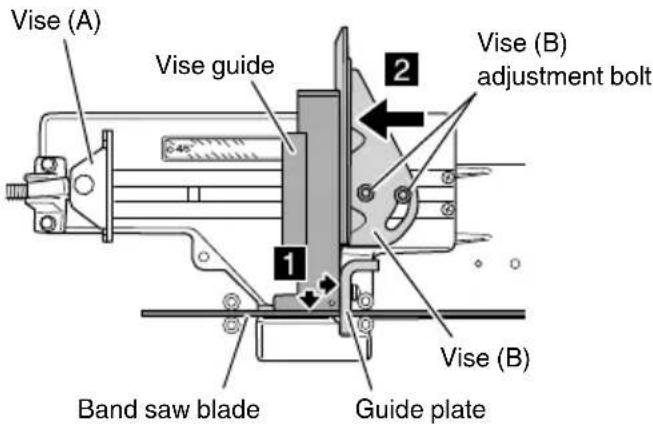
Fig. 8
NOTE
If a higher level of cutting precision is required, adjust the vise position using a speed square.
(1) Apply the vise guide to vise (B), and lightly secure the vise guide using vise (A). (Fig. 9)
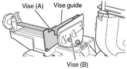
Fig. 9
(2) Loosen the two band saw adjustment bolts using the 8-mm hexagonal wrench supplied as a standard accessory.
Hold the front handle and move the main unit up and down to adjust its angle so that a uniform amount of clearance is created between the side of the vise guide and the band saw blade. (Fig. 10)
(3) Tighten the two band saw adjustment bolts to firmly secure hinge (B).
NOTE
If a higher level of cutting precision is required, adjust the vise position using a speed square.
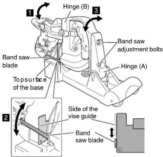
Fig. 10
5. Setting the cutting load
In order to set the cutting load, lift and hold the main unit at the upper limit position, then change the position of the spring stopper. (Fig. 11)
When cutting thin wall steel pipes (with a wall thickness of 2 mm or less), PVC, or plastic materials, set the cutting load to "Light load" or "Lightest load".
NOTE
- When setting the cutting load, be sure to lift the main unit to the upper limit position.
If the spring stopper is pressed in when the main unit is in a low position, the force of the spring will be applied in the opposite direction, preventing the main unit from being able to be lifted to the upper limit position.
- Setting a lighter cutting load increases the length of time required to cut workpieces, however, cutting precision will be improved.
| Pull out the spring stopper.(Remove it from surfaceA.) | "Heavy load" |
| Insert it into hole1. | "Medium load" |
| Insert it into hole2 | "Light load" |
| Insert it into hole3. | "Lightest load" |
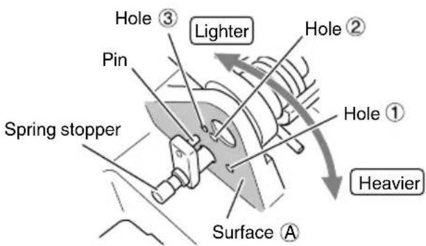
Fig. 11
6. Securing workpieces
Vise (A) of the band saw stand can be moved faster when the clutch is released, and can be used to press a workpiece when the clutch is applied. You can carry out your work efficiently by appropriately moving the vise faster and pressing it against workpieces.
(1) Place a workpiece on the top surface of the base, and press it against vise (B).
(2) Release the clutch, and move vise (A) until it comes in contact with the workpiece.
(3) Apply the clutch, and turn the knob clockwise to secure the workpiece. (Fig. 12)
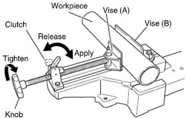
Fig. 12
NOTE
If the clutch cannot be released, turn the knob counterclockwise a little.
English
7. Cutting thin or small diameter workpieces
When cutting a thin or small diameter workpiece, place the vise guide supplied as a standard accessory onto the top of vise (B) to reduce the clearance between the band saw blade and the vise guide. (Fig. 13)
When cutting a thin or small diameter workpiece, if the clearance between the band saw blade and vise (B) is large, the workpiece may be deformed or vibrate in a swinging manner.
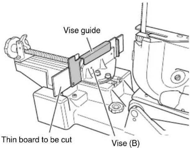
Fig. 13
8. Angle cutting (Fig. 14)
When you adjust the angle of vise (B), you can cut workpieces at an angle between a right-angle and 45 degrees.
(1) Loosen the two vise (B) adjustment bolts that are used to secure vise (B) using the 8-mm hexagonal wrench supplied as a standard accessory.
(2) By checking with the angle scale, rotate vise (B) to orient its workpiece side at the desired angle.
(3) After adjusting the angle, firmly tighten the two vise (B) adjustment bolts to secure vise (B).
(4) When the angle cutting work is finished, return vise (B) to a right-angle position.
(See "Adjustment of the perpendicularity between vise (B) and the band saw blade".)
NOTE
In order to improve the precision of angle cutting, apply an angle gauge to the side of the band saw blade and the workpiece side of vise (B) when securing vise (B).
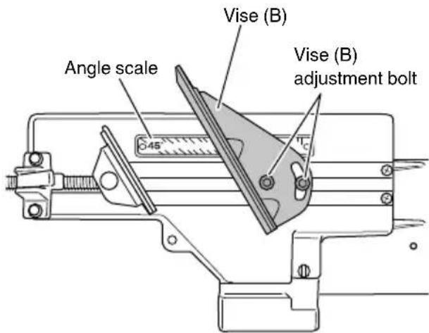
Fig. 14
9. Contour cutting work
WARNING
Be sure to correctly install the protective cover, contour table, and slide cover before use.
CAUTION
If the band saw blade is locked during the cutting operation, immediately turn the switch off to stop the operation.
(1) Lift the main unit to the upper limit position, then lower it a little, and hold it in a position where the main unit is perpendicular to the top surface of the base. In this position, firmly tighten the stopper bolt of the hinge to secure the main unit.
NOTE
If the stopper bolt is tightened although the main body is not in a perpendicular orientation, the main unit may wobble and cut the contour table.
(2) While placing the contour table on the guide plate, align the groove with the band saw blade.
(3) Secure the contour table using vise (B).
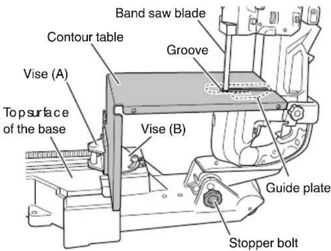
Fig. 15
(1) Remove the M8 bolt. As this bolt is also used to fasten the bearing holder, be careful not to drop the bearing holder.
(2) Insert the protrusion on the slide cover into the slotted hole in pulley guard (B), and tighten the M8 bolt to secure it.
(3) Correctly install the slide cover using the 5-mm butterfly bolt. Before tightening the bolt, adjust the position of the slide cover according to the height of the workpiece.
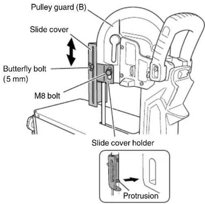
Fig. 16
(1) Turn the lever switch on.
(2) Hold the workpiece with both hands. Slowly slide it on the contour table to the band saw blade to cut its contours.
(3) Press the workpiece against the band saw blade by exerting a load that is not excessive to the point where it warps the blade. Exercise care not to apply excessive loads to the blade.
NOTE
Turn the lever switch off each time you finish cutting workpieces.
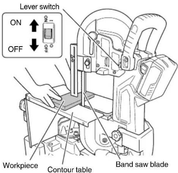
Fig. 17
- Moving the band saw installed on the band saw stand
When moving the band saw installed on the band saw stand, move the main unit down to the lower limit position as shown in the figure below. Tighten the stopper bolt so that the main unit does not move up, then hold both ends of the base. (Fig. 18-a)
The band saw stand has wheels, which enables you to hold the front handle and lift the pulley guard (B) side to move the band saw. (Fig. 18-b)
NOTE
Remove the band saw blade and battery even when you move or store the band saw installed on the band saw stand.
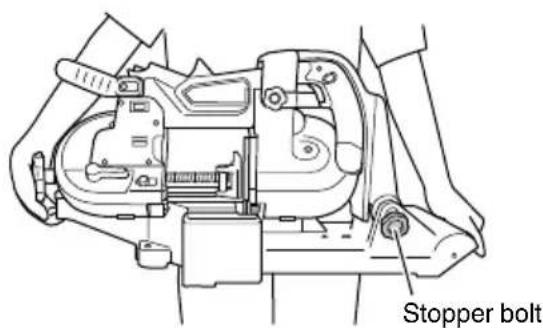
Fig. 18-a
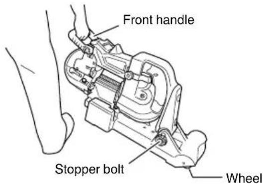
Fig. 18-b
帶鋸機台架安全警告
圖6
natural_image
Line drawing of a quill pen in an inkwell (no text or symbols)
natural_image
Line drawing of a quill pen in an inkwell (no text or symbols)Koki Holdings Co., Ltd.
Shinagawa Intercity Tower A, 15-1, Konan 2-chome, Minato-ku, Tokyo, Japan
- BAND SAW STAND SAFETY WARNINGS
- SYMBOLS
- WARNING
- APPLICATIONS
- HOW TO USE
- Installing the band saw stand and switch holder
- NOTE
- English
- Operating the switch
- Adjusting the lower limit position of the band saw blade
- Adjusting the perpendicularity of the band saw blade
- Setting the cutting load
- Securing workpieces
- Cutting thin or small diameter workpieces
- Angle cutting (Fig. 14)
- Contour cutting work
- CAUTION
- 帶鋸機台架安全警告
- Koki Holdings Co., Ltd.
Brand : HiKOKI
Model : CB12-ST2
Category : Saw