
CS51EA - Saw HiKOKI - Free user manual and instructions
Find the device manual for free CS51EA HiKOKI in PDF.


| Product Type | Circular Saw |
| Brand | HiKOKI |
| Model | CS51EA |
| Blade Diameter | 5-1/2 inches (140 mm) |
| Power Source | Corded Electric |
| Voltage | 120 V (US) or 230 V (EU) |
| Input Power | 1200 W |
| No-Load Speed | 5000 RPM |
| Cutting Depth at 90° | 1.9 inches (48 mm) |
| Cutting Depth at 45° | 1.3 inches (33 mm) |
| Weight | 4.5 kg (9.9 lbs) |
| Dimensions (L x W x H) | 300 x 200 x 250 mm |
| Blade Arbor Size | 20 mm (0.787 inches) |
| Max Cutting Capacity (wood) | 48 mm at 90°, 33 mm at 45° |
| Included Accessories | Saw blade, wrench, rip fence |
| Safety Features | Lock-off button, blade guard |
| Dust Extraction | Compatible with vacuum adapter |
| Maintenance | Clean after use, check carbon brushes regularly |
| Repairability | Spare parts available from service centers |
| Warranty | 1 year limited warranty |
Frequently Asked Questions - CS51EA HiKOKI
User questions about CS51EA HiKOKI
0 question about this device. Answer the ones you know or ask your own.
Ask a new question about this device
Download the instructions for your Saw in PDF format for free! Find your manual CS51EA - HiKOKI and take your electronic device back in hand. On this page are published all the documents necessary for the use of your device. CS51EA by HiKOKI.
USER MANUAL CS51EA HiKOKI
natural_image
Line drawing of a chain drive inside a circular frame (no text or symbols)



natural_image
Diagram of a chain drive with a hand operating the blade (no text or symbols)


natural_image
Technical line drawing of a chain-linking device with labeled component '2' (no text or symbols beyond label)

natural_image
Line drawing of hands using a mechanical device to adjust or install a component (no text or symbols present)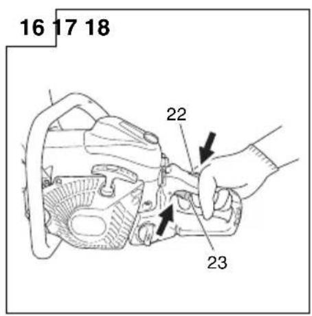


natural_image
Illustration of hands using a chain saw to cut a circular saw (no text or symbols)


natural_image
Simple line drawing of a knife cutting through a circular saw (no text or symbols)







natural_image
Line drawing of a hand holding a small electronic device with a scroll wheel (no text or symbols)



natural_image
Simple line drawing of a curved pipe or tube with a horizontal bar on top, no text or symbols present.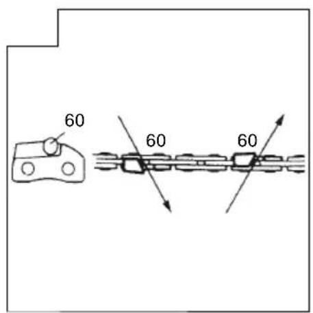

MEANINGS OF SYMBOLS
NOTE: Some units do not carry them.
| Symbols⚠ WARNINGThe following show symbols used for the machine. Be sure that you understand their meaning before use. | |||
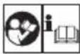 | It is important that you read, fully understand and observe the following safety precautions and warnings. Careless or improper use of the unit may cause serious or fatal injury. |  | Emergency stop |
 | Read, understand and follow all warnings and instructions in this manual and on the unit. |  | Fuel and oil mixture |
 | Always wear eye, head and ear protectors when using this unit. |  | Chain oil fi II |
 | Warning, kickback danger. Be careful of possible sudden and accidental upward and/or backward motion of the guide bar. | [T380] | Carburetor adjustment - Idle speed |
 | One-handed usage not permitted. While cutting, hold saw firmly with both hands with thumb firmly locked around front handle. | [K247] | Carburetor adjustment - Low speed mixture |
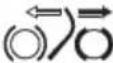 | Chain brake Carburetor adjustment - High speed mixture | [X9CW] | |
 | Choke Oil pump adjustment |  | |
| [###] | On/Start Priming pump |  | |
| ### | Off /Stop Decompression valve |  | |
Contents
WHAT IS WHAT? 7
WARNINGS AND SAFETY INSTRUCTIONS 8
SPECIFICATIONS 9
ASSEMBLY PROCEDURES 10
OPERATING PROCEDURES 10
MAINTENANCE....12
Parts breakdown
WHAT IS WHAT?
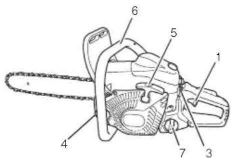
- Throttle lever: Device activated by the operator's finger, for controlling the engine speed.
- Throttle lever lockout: Device that operation of the throttle lever until manually released.
- Stop switch: Device for allowing the engine to be started or stopped.
- Oil tank cap: For closing the oil tank.
- Recoil starter: Pull handle to start the engine.
- Front handle: Support handle located at or towards the front of the engine housing.
- Fuel tank cap: For closing the fuel tank.
- Choke lever: Device for enriching the fuel/air mixture in the carburetor, to aid starting.
- Priming pump; Device for supplying extra fuel, to aid starting.
- Decompression valve: Device for reducing the compression pressure to aid starting.
- Guide bar: The part that supports and guides the saw chain.
- Saw chain: Chain, serving as a cutting tool.
- Chain brake (Front hand guard): Device for stopping or locking the chain.
- Spiked bumper: Device for acting as a pivot when in contact with a tree or log.
- Chain catcher: Device for restraining the saw chain.
- Guide bar cover: Device for covering the guide bar and saw chain when the unit is not being used.
- Combi box spanner: The tool for removing or installing a spark plug and tensioning the saw chain.
- Handling instructions: Included with unit. Read before operation and keep for future reference to learn proper, safe techniques.


WARNINGS AND SAFETY INSTRUCTIONS
Operator safety
○ Always wear a safety face shield or goggles.
○ Gloves should be used when sharpening chain.
○ Always wear safety protective equipment such as jacket, trousers, gloves, helmet, boots with steel toe-caps and non-slip soles, and eye, ear and leg protection equipment whenever you use a chain saw. For working in trees the safety boots must be suitable for climbing techniques. Do not wear loose clothing, jewelry, short pants, sandals or go barefoot.
Secure hair so it is above shoulder length.
☐ Do not operate this tool when you are tired, ill or under the influence of alcohol, drugs or medication.
○ Never let a child or inexperienced person operate the machine.
○ Wear hearing protection. Pay attention to your surroundings.
Be aware of any bystanders who may be signaling a problem. Remove safety equipment immediately upon shutting off engine.
○ Wear head protection.
Never start or run the engine inside a closed room or building. Breathing exhaust fumes can kill.
☐ For respiratory protection, wear a protection mask while emitting the chain oil mist and dust from sawdust.
○ Keep handles free of oil and fuel.
○ Keep hands away from cutting equipment.
○ Do not grab or hold the unit by the cutting equipment.
When the unit turned off, make sure the cutting attachment has stopped before the unit is set down.
When operation is prolonged, take a break from time to time so that you may avoid possible Hand-Arm Vibration Syndrome (HAVS) which is caused by vibration.
○ The operator must obey the local regulations of cutting area.
WARNING
○ Antivibration systems do not guarantee that you will not sustain Hand-Arm Vibration Syndrome or carpal tunnel syndrome.
Therefore, continual end regular users should monitor closely the condition of their hands and fingers. If any of the above symptoms appear, seek medical advice immediately.
○ Long or continuous exposure to high noise levels may cause permanent hearing impairment. Always wear approved hearing protection when operating a unit/machine.
☐ If you are using any medical electric/electronic devices such as a pacemaker, consult your physician as well as the device manufacturer prior to operating any power equipment.
Unit/machine safety
☐ Inspect the entire unit/machine before each use. Replace damaged parts. Check for fuel leaks and make sure all fasteners are in place and securely tightened.
○ Replace parts that are cracked, chipped or damaged in any way before using the unit/machine.
○ Make sure the side case is properly attached.
○ Keep others away when making carburetor adjustments.
○ Use only accessories as recommended for this unit/machine by the manufacturer.
☐ Never let the chain strike any obstacle. If the chain makes contact, the machine should be stopped and checked carefully.
○ Make sure the automatic oiler is working. Keep the oil tank filled with clean oil. Never let chain run dry on the bar.
All chain saw service, other than the items listed in the operator's/ owner's manual, should be performed by HiKOKI Authorized Service Centers. (For example, if improper tools are used to remove the flywheel or if an improper tool is used to hold the flywheel in order to remove the clutch, structural damage to the flywheel could occur and could subsequently cause the flywheel to burst.)
WARNING
☐ Never modify the unit/machine in any way. Do not use your unit/machine for any job except that for which it is intended.
Never use chain saw without any safety equipment or that has faulty safety equipment. It could result in serious personal injury.
○ Using guide bar/chain other than recommended by the manufacturer which are not approved, could result in a high risk of personal accidents or injury.
Fuel safety
○ Mix and pour fuel outdoors and where there are no sparks or flames.
○ Use a container approved for fuel.
☐ Do not smoke or allow smoking near fuel or the unit/machine or while using the unit/machine.
○ Wipe up all fuel spills before starting engine.
○ Move at least 3 m away from fueling site before starting engine.
- Stop engine and let it cool for a few minutes before removing fuel tank cap.
Empty the fuel tank before storing the unit/machine. It is recommended that the fuel be emptied after each use. If fuel is left in the tank, store so fuel will not leak.
Store unit/machine and fuel in area where fuel vapors cannot reach sparks or open flames from water heaters, electric motors or switches, furnaces, etc.
WARNING
Fuel is easy to ignite or get explosion or inhale fumes, so that pay special attention when handling or filling fuel.
Cutting safety
○ Do not cut any material other than wood or wooden objects.
☐ For respiratory protection, wear an aerosol protection mask when cutting the wood after insecticide has been applied.
Keep others including children, animals, bystanders and helpers outside the hazard zone. Stop the engine immediately if you are approached.
○ Hold the unit/machine firmly with the right hand on the rear handle and the left hand on the front handle.
Keep firm footing and balance. Do not over-reach.
Keep all parts of your body away from the muffler and cutting attachment when the engine is running.
○ Keep Bar/Chain below waist level.
Before felling a tree, the operator must be accustomed to the sawing techniques of the chain saw.
○ Be sure to pre-plan a safe exit from a failing tree.
While cutting, hold the unit/machine firmly with both hands with thumb firmly locked around front handle, and stand with feet well balanced and your body balanced.
○ Stand to the side of the saw when cutting - never directly behind it.
○ Always keep the spiked bumper face to a tree, because the chain may suddenly be drawn into a tree, if so equipped.
When completing a cut, be ready to hold up the units as it breaks into clear, so it will not follow through and cut your legs, feet or body, or contact an obstruction.
○ Be alert against kickback (when saw kicks up and back at operator). Never cut with the nose of the bar.
When relocating to a new work area, be sure to shut off the machine and ensure that all cutting attachments are stopped.
○ Never place the machine on the ground when running.
○ Always ensure that the engine is shut off and any cutting attachments have completely stopped before clearing debris or removing grass from the cutting attachment.
○ Always carry a first-aid kit when operating any power equipment.
Never start or run the engine inside a closed room or building and/or near the inflammable liquid. Breathing exhaust fumes can kill.
Maintenance safety
○ Maintain the unit/machine according to recommended procedures.
○ Disconnect the spark plug before performing maintenance except for carburetor adjustments.
○ Keep others away when making carburetor adjustments.
○ Use only genuine HiKOKI replacement parts as recommended by the manufacturer.
CAUTION
Do not disassemble the recoil starter. You may get a possibility of personal injury with recoil spring.
WARNING
Improper maintenance could result in serious engine damage or in serious personal injury.
Transport and storage
○ Carry the unit/machine by hand with the engine stopped and the muffler away from your body.
○ Allow the engine to cool, empty the fuel tank, and secure the unit/machine before storing or transporting in a vehicle.
Empty the fuel tank before storing the unit/machine. It is recommended that the fuel be emptied after each use. If fuel is left in the tank, store so fuel will not leak.
○ Store unit/machine out of the reach of children.
○ Clean and maintain the unit carefully and store it in a dry place.
○ Make sure stop switch is off when transporting or storing.
When transporting or storage, cover chain with guide bar cover. If situations occur which are not covered in this manual, take care and use common sense. Contact HiKOKI Authorized Service Centers if you need assistance. Pay special attention to statements preceded by the following words:
WARNING
Indicates a strong possibility of severe personal injury or loss of life, if instructions are not followed.
CAUTION
Indicates a possibility of personal injury or equipment damage, if instructions are not followed.
NOTE
Helpful information for correct function and use.
WARNING
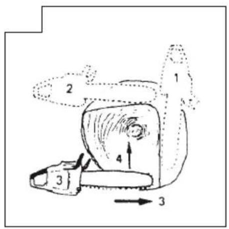
KICKBACK DANGER (Fig. 1)
One of the most severe dangers when working with a chain saw is the possibility of kickback. Kickback may occur when the upper tip of the guide bar touches an object, or when the wood closes in and pinches the saw chain in the cut. Tip contact in some cases may cause a lightning fast reverse reaction, kicking the guide bar up and back toward you. Pinching the saw chain along the top of the guide bar may also push the guide bar rapidly back towards you. Either of these reactions may cause you to lose control of the saw which could result in serious personal injury. Even though your saw has safety built into its design, you should not rely on these safety features exclusively. Know where your bar tip is at all times. Kickback does occur if you allow the kickback zone (1) of the bar to touch an object. Do not use that area. Kickback from pinching is caused by a cut closing and pinching the upper side of the guide bar. Study your cut and make sure it will open as you cut through. Maintain control when the engine is running by always keeping a firm grip on the saw with your right hand on the rear handle, your left hand on the front handle and your thumbs and fingers encircling the handles. Always hold the saw with both hands during operation and cut at high engine speed. Follow manufacturer's sharpening and maintenance instructions for the saw chain. The lack of this maintenance may increase the possibility of kickback.
SPECIFICATIONS
○ Code "CS" of model name means "Chain saw"
| Model | CS51EA (40S) CS51EA (45S) | CS51EA (50S) | |
| Type of equipment Chain saw, portable | |||
| Engine Size (cm3) 50.1 | |||
| Spark Plug NGK BPMR-7A | |||
| Fuel Tank Capacity (cm3) | 530 | ||
| Chain Oil Tank Capacity (cm3) | 270 | ||
| Dry Weight (kg)(Without guide bar and chain) | 5.1 | ||
| Chain pitch (mm) | 8.26 | ||
| Chain gauge (mm) | 1.27 | ||
| Sound pressure level LpA (dB (A)) by ISO 22868EquivalentUncertainty | 100.91 | ||
| Sound power level LwA (dB (A)) by ISO 22868MeasuredUncertainty | 1132 | ||
| Sound power level LwA (dB (A)) by 2000/14/ECMeasuredGuaranteed | 114117 | ||
| Vibration level (m/s2) by ISO 22867Front handleRear handleUncertainty | 2.02.10.8 | 2.02.10.8 | 2.02.10.8 |
| Guide bar length (mm) | 400 | 450 | 500 |
| Type of chain | 95VPX(Oregon) | 20BPX(Oregon) | |
| Max. engine powerby ISO 7293 (kW) | 2.5 | ||
| Max. engine speed (min-1) | 13500 | ||
| Idle engine speed (min1) | 3000 | ||
| Specifi c fuel consumption at maximum enginepower (g/kWh) | 439 | ||
| Max. chain speed (m/sec) | 26.0 | ||
| Sprocket (number of teeth) | 7 | ||
NOTE: Equivalent noise level/vibration levels are calculated as the time-weighted energy total for noise/vibration levels under various working conditions with the following time distribution: 1/3 idle, 1/3 full, 1/3 racing speed. *All data subject to change without notice.
ASSEMBLY PROCEDURES
WARNING
Never try to start engine without side case, bar and chain securely fastened.
- Pull the front hand guard (2) toward the front handle to check that the chain brake is disengaged. (Fig. 2)
-
Remove guide bar clamp nuts (3). Remove the side case (4). (Fig. 3)
-
Install the guide bar (5) onto the bolts (6), then push it toward the sprocket (7) as far as it will go.
-
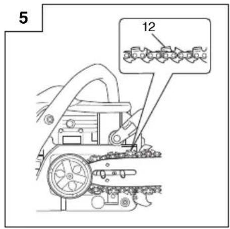
Confirm the direction of saw chain (12) is correct as in the figure, and align the chain on the sprocket. (Fig. 5)
-
Guide the chain drive links into the bar groove all around the bar.
-
Install the side case (4) onto the bolts (6). Make sure that the boss of chain tension adjust bolt (8) fits into the hole (9) of the bar. (Fig. 4) The brake lever (11) of the side case must fit the groove (10) on the side of the front hand guard.
Then tighten the guide bar clamp nuts (3) by hand that allows the guide bar end to move up and down easily. (Fig. 3)
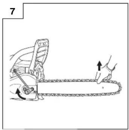
- Raise the bar end, and tighten the chain (12) by turning the tension adjustment bolt (13) clockwise. To check proper tension, lightly lift up the center of chain and there should be about 0.5 - 1.0 mm clearance (14) between bar and edge of drive link. (Fig. 6, 7)
CAUTION
PROPER TENSION IS EXTREMELY IMPORTANT
-
Raise the bar end and securely tighten the guide bar clamp nuts with the combi box spanner. (Fig. 7)
-
A new chain will stretch so adjust the chain after a few cuts and watch chain tension carefully for the first half hour of cutting.
NOTE
Check the chain tension frequently for optimum performance and durability.
CAUTION
When the chain is excessively tightened, the bar and chain will be damaged rapidly. Conversely, when the chain is excessively loosened, it may get out of the groove in the bar.
○ Always wear gloves when touching the chain.
WARNING
During operation, hold chain saw firmly with both hands. A single hand operation may cause serious injury.
OPERATING PROCEDURES
Fuel (Fig. 8)
WARNING
☐ The chain saw is equipped with a two-stroke engine. Always run the engine on fuel, which is mixed with oil. Provide good ventilation, when fueling or handling fuel.
Fuel contains highly flammable and it is possible to get the serious personal injury when inhaling or spilling on your body. Always pay attention when handling fuel. Always have good ventilation when handling fuel inside building.
Fuel
○ Always use branded 89 octane unleaded gasoline.
Use genuine two-cycle oil or use a mix between 25:1 to 50:1, please consult the oil bottle for the ratio or HiKOKI Authorized Service Centers.
☐ If genuine oil is not available, use an anti-oxidant added quality oil expressly labeled for air-cooled 2-cycle engine use (JASO FC GRADE OIL or ISO EGC GRADE). Do not use BIA or TCW (2-stroke water-cooling type) mixed oil.
○ Never use multi-grade oil (10 W/30) or waste oil.
○ Always mix fuel and oil in a separate clean container.
Always start by filling half the amount of gasoline, which is to be used.
Then add the whole amount of oil. Mix (shake) the fuel mixture. Add the remaining amount of gasoline.
Mix (shake) the fuel-mix thoroughly before filling the fuel tank.
Fueling
WARNING (Fig. 9)
○ Always shut off the engine before refueling.
○ Slowly open the fuel tank (15), when filling up with fuel, so that possible overpressure disappears.
○ Tighten the fuel cap carefully, after fueling.
○ Always move the unit at least 3 m from the fueling area before starting.
○ Always wash any spilled fuel from clothing imme soap.
○ Be sure to check any fuel leaking after refueling.
Before fueling, clean the tank cap area carefully, to ensure that dirt falls into the tank. Make sure that the fuel is well mixed by shaking the container, before fueling.
Chain oil (Fig. 9)
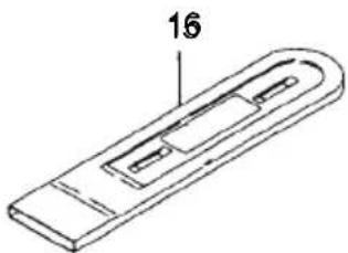
Fill up with chain oil (16). Always use good quality chain oil. When the engine is running, the chain oil is automatically discharged.
NOTE
When pouring fuel (15) or chain oil (16) into the tank, place the unit with cap side up. (Fig. 9)
ADJUSTMENT OF CHAIN OIL SUPPLY
The chain oil quantity discharged through the lubrication system is adjusted to the maximum in the factory. Adjust the quantity in accordance with the operating condition.
Turn the adjusting screw (17) counterclockwise to increase the quantity and turn it clockwise to decrease the quantity. (Fig. 10)
Chain brake operation (Fig. 2, 11)
Chain brake is designed to activate in an emergency such as kick-back action.
Application of brake is made by moving the front hand guard towards the bar. During the chain brake operation, even if the throttle lever is pulled, the engine speed does not increase and the chain does not turn. To release the brake, pull the front hand guard toward the front handle.
If the engine keeps rotating at high speed with the brake engaged, the clutch will overheat causing trouble.
When the brake engages during operation, immediately release the throttle lever to slow down the engine.
How to confirm the activation of the chain brake
1) Turn off the engine.
2) Holding the chain saw horizontally, release your hand from the front handle, hit the tip of the guide bar to a stump or a piece of wood, and confirm brake operation. Operating level varies by bar size.

natural_image
Line drawing of a person using a chain mill to cut a tree stump with a downward arrow (no text or symbols)In case the brake is not effective, ask HiKOKI Authorized Service Centers for inspection and repairs.
Starting (Fig. 11 - 16)
CAUTION
Before starting, make sure chain brake is engaged and that the bar/chain does not touch anything. (Fig. 11)
-
Set ignition switch (18) to ON position. (Fig. 12)
*Push priming pump (20) several times so that fuel flows through bulb into carburetor. (Fig. 13) -
Pull the choke lever (19) to choked position (Fig. 13).
This will automatically lock to the half-throttle. -
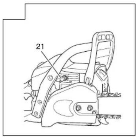
Push the decompression valve (21).
The valve (21) will automatically return to the original position once the engine has started (Fig. 14).
-
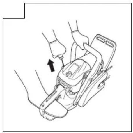
Pull recoil starter briskly, taking care to keep the handle in your grasp and not allowing it to snap back. (Fig. 15)
-
When you hear first ignition, return the choke lever (19) all the way in. (Fig. 13)
-
Push the decompression valve.
-
Pull recoil starter briskly again in the aforementioned manner. (Fig. 15)
NOTE
If engine does not start, repeat procedures from 2 to 7.
- As soon as engine start, pull throttle lever (23) throttle lever lockout (22) and release immediately. (Fig. 16) Then half-throttle is disengaged.
Pull the front hand guard (2) toward the front handle to disengage the chain brake.
Allow the engine about 2-3 minutes to warm up before subjecting it to any load.
Do not run the engine at high speed without the load to avoid shortening the life of the engine.
WARNING
Do not carry the machine with the engine running.
Stopping (Fig. 17)
Decrease engine speed, and push ignition switch (18) to stop position.
WARNING
○ Do not overreach or cut above shoulder height.
○ Use extra caution when felling, and do not use the saw in a nose-high position or above shoulder height.
CHAIN CATCHER
The chain catcher is located on the power head just below the chain to further prevent the possibility of a broken chain striking the chain saw user.
WARNING
Do not stand in-line with chain when cutting.
BASIC TECHNIQUES FOR MAKING FELLING, LIMBING AND BUCKING CUTS
The intention of the following information is to provide you with the general introduction to wood cutting techniques.
WARNING
This information does not cover all specific situations, which may depend on differences in terrain, vegetation, kind of wood, form and size of trees, etc. Consult HiKOKI Authorized Service Centers, forestry agent or local forestry schools for advice on specific woodcutting problems in your area. This will make your work more efficient and safer.
○ Avoid cutting in adverse weather conditions, such as dense fog, heavy rain, bitter cold, high winds, etc.
Adverse weather is often tiring to work in and creates potentially dangerous conditions such as slippery ground.
High winds may force the tree to fall in an unexpected direction causing property damage or personal injury.
CAUTION
Never use a chain saw to pry or for any purpose for which it is not intended.
WARNING
○ Avoid stumbling on obstacles such as stumps, roots, rocks, branches and fallen trees. Watch out for holes and ditches. Be extremely cautious when working on slopes or uneven ground. Shut off the engine when moving from one work place to another.
Always cut at wide open throttle. A slow moving chain can easily catch and force the saw to jerk.
○ Never use the saw with only one hand.
You cannot control the saw properly and you may lose control and injure yourself severely.
Keep the saw body close to your body to improve control and reduce strain.
When cutting with the bottom part of the chain the reactive force will pull the saw away from you towards the wood you are cutting. The saw will control the feeding speed and sawdust will be directed towards you. (Fig. 18)
When cutting with the upper part of the chain the reactive force will push the saw towards you and away from the wood you are cutting. (Fig. 19)
○ There is a risk of kickback if the saw is pushed far enough so that you begin to cut with the nose of the bar.
The safest cutting method is to cut with the bottom part of the chain. Sawing with the upper part makes it much more difficult to control the saw and increases the risk of kickback.
☐ In case the chain locked, immediately release the throttle lever. If the throttle lever keeps rotating at high speed with the chain locked, the clutch will overheat causing trouble.
NOTE
I on always keep the spiked bumper face to a tree, because the chain may suddenly be drawn into a tree.
FELLING
Felling is more than cutting down a tree. You must also bring it down as near to an intended place as possible without damaging the tree or anything else.
Before felling a tree, carefully consider all conditions which may effect the intended direction, such as:
Angle of the tree. Shape of the crown. Snow load on the crown. Wind conditions. Obstacles within tree range (e.g., other trees, power lines, roads, buildings, etc.).
WARNING
○ Always observe the general conditions of the tree. Look for decay and rot in the trunk which will make it more likely to snap and start to fall before you expect it.
○ Look for dry branches, which may break and hit you when you are working.
Always keep animals and people at least twice the tree length away while felling. Clear away shrubs and branches from around the tree.
Prepare a path of retreat away from the felling direction.
BASIC RULES FOR FELLING TREES
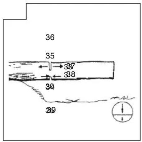
Normally the felling consists of two main cutting operations, notching and making the felling cut. Start making the upper notch cut on the side of the tree facing the feeling direction. Look through the kerf as you saw the lower cut so you do not saw too deep into the trunk. The notch should be deep enough to create a hinge of sufficient width and strength. The notch opening should be wide enough to direct the fall of the tree as long as possible. Saw the felling cut from the other side of the tree between one and two inches (3–5 cm) above the edge of the notch. (Fig. 20)
- Felling direction
- 45° minimum notch opening
- Hinge
- Felling cut
Never saw completely through the trunk. Always leave a hinge.
The hinge guides the tree. If the trunk is completely cut through, you lose control over the felling direction.
Insert a wedge or a felling lever in the cut well before the tree becomes unstable and starts to move. This will prevent the guide bar from binding in the felling cut if you have misjudged the falling direction. Make sure no people have come into the ran falling tree before you push it over.
FELLING CUT, TRUNK DIAMETER MORE THAN TWICE GUIDE BAR LENGTH
Cut a large, wide notch. Then cut a recess into the center of the notch. Always leave a hinge on both sides of the center cut. (Fig. 21) Complete the felling cut by sawing around the trunk as in the Fig. 22.
WARNING
These methods are extremely dangerous because they involve the use of the nose of guide bar and can result in kickback. Only properly trained professionals should attempt these techniques.
LIMBING
Limbing is removing the branches from a feller tree.
WARNING
A majority of kickback accidents occur during limbing.
Do not use the nose of the guide bar. Be extremely cautious and avoid contacting the log, other limbs or objects with the nose of the guide bar. Be extremely cautious of limbs under tension. They can spring back towards you and cause loss of control resulting in injury. (Fig. 23)
Stand on the left side of the trunk. Maintain a secure footing and rest the saw on the trunk. Hold the saw close to you so that you are in full control of it. Keep well away from the chain. Move only when the trunk is between you and the chain. Watch out for spring back of limbs under tension. 11
LIMBING THICK BRANCHES
When limbing thick branches, the guide bar may get pinched easily. Branches under tension often snap up, so cut troublesome branches in small steps. Apply the same principles as for cross cutting. Think ahead and be aware of the possible consequences of all your actions.
CROSS CUTTING/BUCKING
Before starting to cut through the log, try to imagine what is going to happen. Look out for stresses in the log and cut through it in such a manner that the guide bar will not get pinched.
CROSS CUTTING LOGS, PRESSURE ON TOP
Take a firm stance. Begin with an upper cut. Do not cut too deeply, about 1/3 of the log diameter is enough. Finish with a bottom cut. The saw cuts should meet. (Fig. 24)
-
Relieving cut
-
Cross cut
-
Pressure on top
-
Pressure side
-
Tension side
-
Relative depth of saw cuts
THICK LOG, LARGER THAN GUIDE BAR LENGTH
Begin by cutting on the opposite side of the log. Pull the saw towards you, followed by previous procedure. (Fig. 25)
If the log is lying on the ground make a boring cut to avoid cutting into the ground. Finish with a bottom cut. (Fig. 26)

WARNING
KICKBACK DANGER
Do not attempt a boring cut if you are not properly trained. A boring cut involves the use of the nose of the guide bar and can result in kickback.
CROSS CUTTING LOGS, PRESSURE ON BOTTOM
Take a firm stance. Begin with a bottom cut. The depth of the cut should be about 1/3 of the log diameter.
Finish with an upper cut. The saw cuts should meet. (Fig. 27)
-
Relieving cut
-
Cross cut
-
Pressure on bottom
-
Tension side
-
Pressure side
-
Relative depth of saw cuts
THICK LOG, LARGER THAN GUIDE BAR LENGTH
Begin by cutting on the opposite side of the log. Pull the saw towards you, followed by previous procedure. Make a boring cut if the log is close to the ground. Finish with a top cut. (Fig. 28)

WARNING
KICKBACK DANGER
Do not attempt a boring cut if you are not properly trained. A boring cut involves the use of the nose of the guide bar and can result in kickback. (Fig. 29)
IF THE SAW GETS STUCK
Stop the engine. Raise the log or change its position, using a thick branch or pole as a lever. Do not try to pull the saw free. If you do, you can deform the handle or be injured by the saw chain if the saw is suddenly released.
MAINTENANCE
MAINTENANCE, REPLACEMENT OR REPAIR OF THE EMISSION CONTROL DEVICES AND SYSTEM MAY BE PERFORMED BY ANY NON-ROAD ENGINE REPAIR ESTABLISHMENT OR INDIVIDUAL.
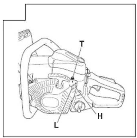
Carburetor adjustment (Fig. 30)
In the carburetor, fuel is mixed with air. When the engine is test run at the factory, the carburetor is adjusted. A further adjustment may be required, according to climate and altitude. The carburetor has one adjustment possibility:
T = Idle speed adjustment screw.
Idle speed adjustment (T)
Check that the air filter is clean. When the idle speed is correct, the cutting attachment will not rotate. If adjustment is required, close (clockwise) the T-screw, with the engine running, until the cutting attachment starts to rotate. Open (counter-clockwise) the screw until the cutting attachment stops. You have reached the correct idle speed when the engine runs smoothly in all positions well below the rpm when the cutting attachment starts to rotate.
If the cutting attachment still rotates after idle speed adjustment, contact HiKOKI Authorized Service Centers.

WARNING
When the engine is idling the cutting attachment must under no circumstances rotate.
NOTE
Do not touch the High speed adjustment (H) and the Low speed adjustment (L).
Those are only for HiKOKI Authorized Service Centers.
If you rotate them, It will cause a serious damage to the machine.
Air fi Iter (Fig. 31)
The air filter (40) must be cleaned from dust and dirt in order to avoid:
○ Carburetor malfunctions.
○ Starting problems.
○ Engine power reduction.
○ Unnecessary wear on the engine parts.
○ Abnormal fuel consumption.
Clean the air filter daily or more often if working in exceptionally dusty areas.
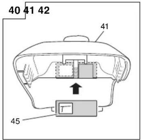
Remove the air filter cover (41) and the filter (40).
Rinse them in warm soap suds. Check that the filter is dry before reassembly. An air filter that has been used for some time cannot be cleaned completely. Therefore, it must regularly be replaced with a new one. A damaged filter must always be replaced.
Spark plug (Fig. 32)
The spark plug condition is influenced by:
○ An incorrect carburetor setting.
○ Wrong fuel mixture (too much oil in the gasoline)
○ A dirty air filter.
○ Hard running conditions (such as cold weather).
These factors cause deposits on the spark plug electrodes, which may result in malfunction and starting difficulties. If the engine is low on power, difficult to start or runs poorly at idling speed, always check the spark plug first. If the spark plug is dirty, clean it and check the electrode gap. Readjust if necessary. The correct gap is 0.6 mm. The spark plug should be replaced after about 100 operation hours or earlier if the electrodes are badly eroded.
NOTE
In some areas, local law requires using a resistor spark plug to suppress ignition signals. If this machine was originally equipped with resistor spark plug, use same type of spark plug for replacement.
Oiler port (Fig. 33)
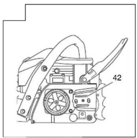
Clean the chain oiler port (42) whenever possible.
Guide bar (Fig. 34)
Before using the machine, clean the groove and oiler port (43) in the bar with the special gauge off ered as an optional accessory.
Side case (Fig. 35)
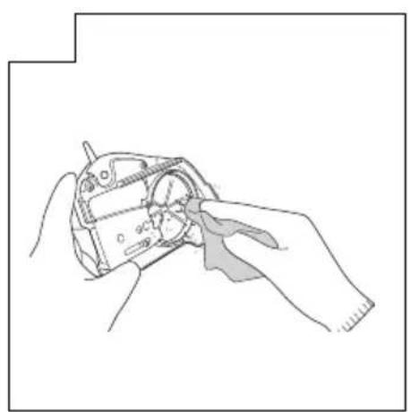
Always keep the side case and drive area clean of saw dust and debris. Periodically apply oil or grease to this area to protect from corrosion as some trees contain high levels of acid.
Fuel fi Iter (Fig. 36)
Remove the fuel filter from the fuel tank and thoroughly wash it in solvent. After that, push the filter into the tank completely.
NOTE
If the fi Iter is hard due to dust and dirt, replace it.
Chain oil fi Iter (Fig. 37)
Remove the oil fi Iter and thoroughly wash it in solvent.
Cleaning the cylinder fins (Fig. 38)
When wood chips are caught between cylinder fins (44), the engine may overheat, resulting in lower output. To avoid this, always keep cylinder fins and fan case clean.
Icing protection system (Fig. 39, 40)
This system is to protect carburetor from icing when the unit is operated in winter time.
- When you need icing system work, remove air filter cover (41). Pull out the shutter (45) from inside the air filter cover and reinstall it in winter time position by turning half-way. (Fig. 39) This will allow heated air to flow from cylinder side to carburetor cabin through the opening (46).
NOTE
When winter time has been over and carburetor will not suffer from icing, make sure that the shutter is reinstalled in ordi position (Fig. 40).
For long-term storage
Drain all fuel from the fuel tank. Start and let engine run until it stops.
Repair any damage which has resulted from use. Clean the unit with a clean rag, or the use of high pressure air hose. Put a few drops of two-cycle engine oil into the cylinder through the spark plug hole, and spin the engine over several times to distribute oil.
Cover the unit and store it in a dry area.
CHAIN SHARPENING
Parts of a cutter (Fig. 41, 42)

WARNING
○ Gloves should be used when sharpening chain.
☐ Be sure to round off the front edge to reduce the chance of kickback or tie-strap breakage.
47. Top plate
48. Cutting corner
49. Side plate
50. Gullet
51. Heel
52. Chassis
53. Rivet hole
54. Toe
55. Depth gauge
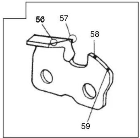
56. Correct angle on top plate (degree of angle depends on chain type)
57. Slightly protruding "hook" or point (curve on non-chisel chain)
58. Top of depth gauge at correct height below top plate
59. Front of depth gauge rounded off
LOWERING DEPTH GAUGES WITH A FILE
1) If you sharpen your cutters with a file holder, check and lower the depth.
2) Check depth gauges every third sharpening.
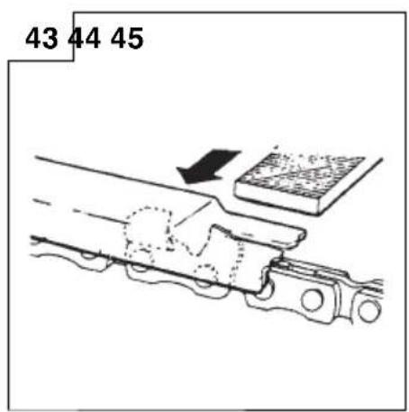
3) Place depth gauge tool on cutter. If depth gauge projects, file it level with the top of the tool. Always file from the inside of the chain toward an outside cutter. (Fig. 43)
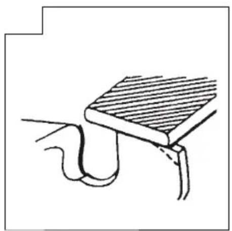
4) Round off front corner to maintain original shape of depth gauge after using depth gauge tool. Always follow the recommended depth gauge setting found in the maintenance or operator manual for your saw. (Fig. 44)
GENERAL INSTRUCTIONS FOR FILING CUTTERS
File (60) cutter on one side of the chain from the inside out. File on forward stroke only. (Fig. 45)
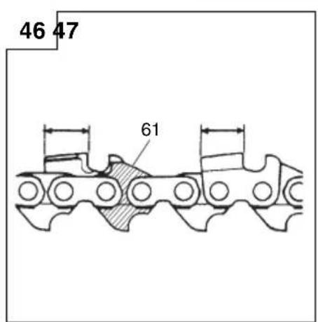
5) Keep all cutters the same length. (Fig. 46)
6) File enough to remove any damage to cutting edges (side plate (62) and top plate (63)) of cutter. (Fig. 47)
NOTE
Do not file or alter the tops of bumper drive links (61). (Fig. 46).
SHARPENING ANGLES FOR SHARPENING SAW CHAIN
| 1. Part Number | 95VPX/20BPX | |
| 2. Pitch | 0.325" | |
| 3. Depth Gauge Setting | 0.025" | |
| 4. Side Plate Filing Angle | 85° | |
| 5. Top Plate Angle | 30° | |
| 6. File Guide Angle | 100° |
Maintenance schedule
Below you will find some general maintenance instructions. For further information please contact HiKOKI Authorized Service Centers.
Daily maintenance
○ Clean the exterior of the unit.
○ Clean the chain oil fi Iter port.
○ Clean the groove and oil filter port in the guide bar.
○ Clean the side case of saw dust.
○ Check that the saw chain is sharp.
☐ Check that the bar nuts are sufficiently tightened.
○ Make sure that the chain transport guard is undamaged and that it can be securely fitted.
☐ Check that nuts and screws are sufficiently tightened. Especially inspect the bolt of muffler and ensure that they are properly tightened before starting engine. Should any of the bolts be loose, retighten them immediately. Fail could result in serious hazard.
☐ Check the tip of the guide bar. Please exchange it for the new one when it is worn out.
☐ Check the band of chain brake. Please exchange it for the new one when it is worn out.
○ Clean the air filter.
Weekly maintenance
○ Check the recoil starter, especially cord.
○ Clean the exterior of the spark plug.
○ Remove the spark plug and check the electrode gap. Adjust it to 0.6 mm or change the spark plug.
○ Clean the cooling fins on the cylinder and check that the air intake at the recoil starter is not clogged.
Monthly maintenance
○ Rinse the fuel tank with gasoline, and clean fuel filter.
○ Clean chain oil filter.
○ Clean the exterior of the carburetor and the space around it.
○ Clean the fan and the space around it.
NOTE
When ordering the parts to HiKOKI Authorized Service Centers, please use the item numbers showing on the parts breakdown section in this instruction.
| BAR NO. | LENGTH-TYPE | CHAIN NO. | |
| MODEL NO. OREGON | 160MLBK041 | 400 mm (16") | 95VPX-66 |
| 180MLBK041 | 450 mm (18") | 95VPX-72 | |
| 200PXBK041 | 500 mm (20") | 20BPX-78 |
標誌的意義
註: 某些裝置並沒有附帶此標誌。

警告與安全指示
操作者安全
natural_image
Illustration of a person using a power saw to cut tree bark (no text or symbols)

경고 및 안전 수칙
작업자 안전 주의사항
natural_image
Illustration of a person using a power saw to cut tree bark (no text or symbols)

CẢNH BÁO VÀ HƯỚNG DẮN AN TOÀN
natural_image
Illustration of a person using a power tool to cut tree bark (no text or symbols)MÀI SẮC XÍCH MÁY CƯA

natural_image
Illustration of a person using a chain mill to cut tree bark with a downward arrow (no text or symbols)natural_image
Illustration of a person using a wooden saw to cut a tree stump with a downward arrow indicating the process (no text or symbols present)
نبدة
natural_image
Simple line drawing of a closed book with visible pages and cover (no text or symbols)
natural_image
Technical line drawing of a mechanical component with labeled part 16 (no text or symbols beyond label)natural_image
Line drawing of a quill pen in an inkwell (no text or symbols)
| ITEMNO. | PART NAME Q'TY | |
| 1 | S T A R T L | 1A |
| 2 CL | EANER COVER (C51) 1 | |
| 3 SH | HUTTER PLATE 1 | |
| 4 COVER SET BOLT 7 | ||
| 5 CY | LINDER COVER (C51) 1 | |
| 6 | C L E A N E | R |
| 7 | K N O B P A | C |
| 8 CL | EANER ELEMENT (B) 1 | |
| 9 CL | EANER ELEMENT (A) 1 | |
| 10 N | UT M6 | 3 |
| 11 B | OLT WASHER M6 | 1 |
| 12 | SPRING HOLDER | 1 |
| 13 | HEX. SOCKET HD. BOLT(W/FLANGE) M6×20 | 1 |
| 14 A | NTIVIBRATION SPRING | 1 |
| 15 D | AMPER SET BOLT | 3 |
| 16 | SEAL LOCK SCREW M4×10 | 18 |
| 17 S | CAVENGING COVER (B) | 1 |
| 18 C | OVER PACKING (C51) | 2 |
| 19 E | XHAUST PIPE (C51) | 1 |
| 20 M | UFFLER GAUZE (C51) | 1 |
| 21 | TAPPING SCREW(W/FLANGE) D5×25 | 2 |
| 22 F | FRONT HANDLE | 1 |
| 23 | TAPPING SCREW(W/FLANGE) D5×20 | 2 |
| 24 | HEX. SOCKET HD. BOLTM4×10 | 5 |
| 25 B | OLT WASHER M4 | 5 |
| 26 M | UFFLER PROTECTOR | 1 |
| 27 | MUFFLER PROTECTORPACKING | 1 |
| 28 M | MACHINE SCREW M4 × 16 | 3 |
| 29 O | IL PIPE (CS40) | 1 |
| 30 O | IL PUMP | 1 |
| 31 | CLIP | |
| 32 | SEAL LOCK HEX. SOCKETHD. BOLT M5×30 | 4 |
| 33 S | EA LOCK SCREW M5 × 12 | 3 |
| 34 S | PIKE | 1 |
| 35 | SEAL LOCK HEX. SOCKETHD. BOLT M5×45 | 2 |
| 36 M | UFFLER CAP | 2 |
| 37 | HEX. SOCKET HD. BOLTM6×20 | 6 |
| 38 | HEX. SOCKET HD. BOLTM5×12 | 5 |
| 39 M | UFFLER (C51) | 1 |
| 40 M | UFFLER PACKING (C51) | 1 |
| 41 | GROMMET | 2 |
| 42 F | UEL PIPE 2.5 ×4×90 | 1 |
| 43 PR | RIMING PUMP COMP. | 1 |
| 44 | DECOMP. | |
| 45 S | PARK PLUG BPMR7A | 1 |
| 46 | INTAKE PACKING (C51) | 1 |
| 47 INTAKE (C51) | 1 | |
| 48 C | AB. INSULATOR RUBBER | 1 |
| 49 | CARBURETOR INSULATOR(C51) | 1 |
| 50 F | UEL PIPE | 1 |
| 51 | CARBURETOR ASS'Y | 1 |
| 52 S | CREW | 1 |
| 53 P | UMP GASKET | 1 |
| 54 P | UMP DIAPHRAGM | 1 |
| ITEMNO. | PART NAME Q'TY | |
| B 55 | NLET SCREEN | 1 |
| 56 | NEEDLE VALVE | 1 |
| 57 | VALVE SPRING | 1 |
| 58 | DIAPHRAGM PACKING-METERING | 1 |
| K 59 | METERING DIAPHRAGM | 1 |
| K60 | DIAPHRAGM COVER-METERING | 1 |
| 61 | IDLE ADJUST SPRING | 1 |
| 62 | IDLE ADJUST SCREW | 1 |
| 63 | HINGE PIN SET SCREW | 1 |
| 64 | CONTROL LEVER | 1 |
| 65 | HINGE PIN | 1 |
| 66 | SET SCREW | 1 |
| 67 | FUEL PIPE | 1 |
| 68 | WASHER 5 | 5 |
| 69 | HEX. SOCKET HD. BOLT M5 × 45 | 2 |
| 70 | CLEANER SUPPORT (C51) | 1 |
| 71 | FUEL PIPE | 1 |
| 72 | CYLINDER | 1 |
| 73 | SCAVENGING COVER (A) | 1 |
| 74 | CYLINDER PACKING (C51) | 1 |
| 75 | PISTON RING | 2 |
| 76 | PISTON (44) M | 1 |
| 77 | CIR CLIP | 2 |
| 78 | PISTON PIN COLLAR (C51) | 2 |
| 79 | ENGINE CASE (B) 1 | |
| 80 | OIL SEAL | 2 |
| 81 | BALL BEARING 6202C3 | 2 |
| 82 | CRANK SHAFT | 1 |
| 83 | CRANK CASE PACKING (C51) | 1 |
| 84 | PISTON PIN | 1 |
| 85 | NEEDLE BEARING (A) | 1 |
| 86 | ENGINE CASE (A) | 1 |
| 87 | REAR DAMPER (C51) | 1 |
| 88 | BRAKE HANDLE | 1 |
| 89 | CAUTION LABEL | 1 |
| 90 | BRAKE LEVER SPRING (B) | 1 |
| 91 | CHOKE ROD RUBBER | 1 |
| 92 | CHOKE BUTTON | 1 |
| 93 | OPERATIONAL PANEL | 1 |
| 94 | STOP SWITCH | 1 |
| 111 | NAME PLATE | 1 |
| 112 | FLANGE NUT M8 | 3 |
| 113 | SIDE CASE SUB | 1 |
| 114 | CHAIN PULLER | 1 |
| 115 | SAW CHAIN | 1 |
| 116 | GUIDE PLATE (B) | 1 |
| 117 | BAR | 1 |
| 118 | OIL GROMMET (A) | 1 |
| 119 | FUEL ^1 PIPE | 1 |
| 120 | BOLT WASHER D5 | 1 |
| 121 | OIL FILTER | 1 |
| 122 | OIL FILTER BODY | 1 |
| 123 | GUIDE PLATE (A) | 1 |
| 124 | DAMPER (C51) | 2 |
| 125 | CHAIN CATCHER | 1 |
| 126 | BRAKE LINK | 1 |
| 127 | BRAKE SPRING | 1 |
| 128 | BRAKE BAND | 1 |
| 129 | NEEDLE ROLLER D3 1 |
| ITEM NO. | PART NAME Q'TY | |
| 130 | BRAKE LINK COVER | 1 |
| 131 | CLUTCH | 1 |
| 132 | CLUTCH WASHER (B) 1 | |
| 133 | CLUTCH HOUSING | 1 |
| 134 | NEEDLE BEARING | 1 |
| 135 | RIM SPROCKET | 1 |
| 136 | CLUTCH WASHER | 1 |
| 137 | OIL PUMP COVER (C51) 1 | |
| 138 | WORM | 1 |
| 139 | AIR VENT SPONGE | 1 |
| 140 | AIR VENT VALVE (B) | 1 |
| 141 | TAPPING SCREW (W/FLANGE) D4 × 16 | 1 |
| 142 | REAR HANDLE GRIP | 1 |
| 143 | THROTTLE LEVER LOCKOUT | 1 |
| 144 | THROTTLE LEVER SPRING | 1 |
| 145 | NUMBER PL ATE | 1 |
| 146 | REAR HANDLE | 1 |
| 147 | SPRING PIN 5 ×25 | 1 |
| 148 | THROTTLE ROD | 1 |
| 149 | THROTTLE LEVER | 1 |
| 150 | AIR VALVE CAP | 1 |
| 151 | INNER CAP | 1 |
| 152 | GROMMET | 1 |
| 153 | PUMP FILTER BODY | 1 |
| 154 | FRONT DAMPER | 1 |
| 155 | SPRING HOLDER | 2 |
| 156 | FLANGED TAPPING SCREW D6 | 2 |
| 157 | ANTIVIBRATION SPRING | 2 |
| 158 | TANK MARK LABEL | 1 |
| 159 | TANK CAP PACKING | 2 |
| 160 | FUEL TANK CAP ASS'Y | 2 |
| 161 | BAND | 1 |
| 162 | PLUG CAP | 1 |
| 163 | CORD (A) | 1 |
| 164 | CORD (B) | 1 |
| 165 | METAL FITTING OF PLUG CAP | 1 |
| 166 | IGNITION COIL | 1 |
| 167 | HEX. SOCKET HD. BOLT (W/FLANGE) M4× 18 | 2 |
| 168 | MAGNETO ASS'Y 1 | |
| 169 | MAGNETO ROTOR | 1 |
| 170 | STARTER PAWL SPRING | 2 |
| 171 | WASHER 0.8 | 2 |
| 172 | STARTER PAWL | 2 |
| 173 | SHIM | 2 |
| 174 | STEP BOLT | 2 |
| 175 | AIR DEFLECTOR | 1 |
| 176 | RECOIL STARTER 1 | |
| 177 | BRAND LABEL | 1 |
| 501 | CHAIN COVER | 1 |
| 502 | COMBI BOX SPANNER | 1 |
Koki Holdings Co., Ltd.
- MEANINGS OF SYMBOLS
- Contents
- WHAT IS WHAT?
- WARNINGS AND SAFETY INSTRUCTIONS
- Operator safety
- WARNING
- Unit/machine safety
- Fuel safety
- Cutting safety
- Maintenance safety
- CAUTION
- Transport and storage
- NOTE
- KICKBACK DANGER (Fig. 1)
- SPECIFICATIONS
- ASSEMBLY PROCEDURES
- OPERATING PROCEDURES
- Fuel (Fig. 8)
- Fuel
- Fueling
- WARNING (Fig. 9)
- Chain oil (Fig. 9)
- ADJUSTMENT OF CHAIN OIL SUPPLY
- Chain brake operation (Fig. 2, 11)
- How to confirm the activation of the chain brake
- Starting (Fig. 11 - 16)
- Stopping (Fig. 17)
- CHAIN CATCHER
- FELLING
- BASIC RULES FOR FELLING TREES
- FELLING CUT, TRUNK DIAMETER MORE THAN TWICE GUIDE BAR LENGTH
- LIMBING
- LIMBING THICK BRANCHES
- CROSS CUTTING/BUCKING
- CROSS CUTTING LOGS, PRESSURE ON TOP
- THICK LOG, LARGER THAN GUIDE BAR LENGTH
- KICKBACK DANGER
- CROSS CUTTING LOGS, PRESSURE ON BOTTOM
- IF THE SAW GETS STUCK
- MAINTENANCE
- Carburetor adjustment (Fig. 30)
- Idle speed adjustment (T)
- Air fi Iter (Fig. 31)
- Spark plug (Fig. 32)
- Oiler port (Fig. 33)
- Guide bar (Fig. 34)
- Side case (Fig. 35)
- Fuel fi Iter (Fig. 36)
- Chain oil fi Iter (Fig. 37)
- Cleaning the cylinder fins (Fig. 38)
- Icing protection system (Fig. 39, 40)
- For long-term storage
- CHAIN SHARPENING
- Parts of a cutter (Fig. 41, 42)
- LOWERING DEPTH GAUGES WITH A FILE
- GENERAL INSTRUCTIONS FOR FILING CUTTERS
- Maintenance schedule
- Daily maintenance
- Weekly maintenance
- Monthly maintenance
- 標誌的意義
- 警告與安全指示
- 操作者安全
- 경고 및 안전 수칙
- 작업자 안전 주의사항
- CẢNH BÁO VÀ HƯỚNG DẮN AN TOÀN
- MÀI SẮC XÍCH MÁY CƯA
- نبدة
- Koki Holdings Co., Ltd.
Brand : HiKOKI
Model : CS51EA
Category : Saw