
C 6UY - Saw HiKOKI - Free user manual and instructions
Find the device manual for free C 6UY HiKOKI in PDF.


| Product Type | Circular Saw |
| Brand | HiKOKI |
| Model | C 6UY |
| Power Input | 1300 W |
| Voltage | 230 V ~ |
| No-Load Speed | 5500 min⁻¹ |
| Blade Diameter | 165 mm |
| Cutting Depth at 90° | 66 mm |
| Cutting Depth at 45° | 46 mm |
| Weight (without cord) | 3.8 kg |
| Bevel Adjustment | 0° to 45° |
| Lower Guard | Automatic retracting |
| Riving Knife | Yes, adjustable |
| Dust Collection | Yes, with dust collector attachment |
| Guide Rail Compatibility | Yes, with included guide rail adapter (compatible with BOSCH, FESTO, MAKITA) |
| Arbor Size | 20 mm (standard) |
| Cord Length | Approx. 2.5 m |
| Sound Pressure Level | 90 dB(A) |
| Sound Power Level | 101 dB(A) |
| Vibration Emission | 2.4 m/s² (cutting chipboard) |
| Insulation | Double |
| Carbon Brushes | Replaceable (use genuine HiKOKI) |
| Application | Wood cutting |
Frequently Asked Questions - C 6UY HiKOKI
User questions about C 6UY HiKOKI
0 question about this device. Answer the ones you know or ask your own.
Ask a new question about this device
Download the instructions for your Saw in PDF format for free! Find your manual C 6UY - HiKOKI and take your electronic device back in hand. On this page are published all the documents necessary for the use of your device. C 6UY by HiKOKI.
USER MANUAL C 6UY HiKOKI
natural_image
Technical line drawing of a mechanical cutting tool with a circular cutter and base mount (no text or symbols)C 7UY
Read through carefully and understand these instructions before use.
2

3

4(A)

4(B)

5

6
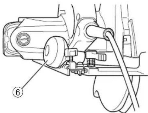
7
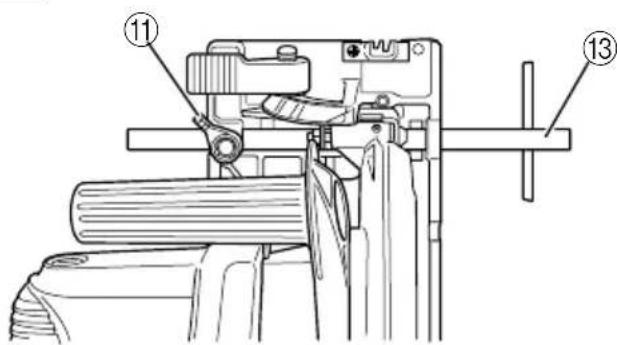
8
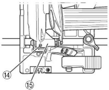
9

10
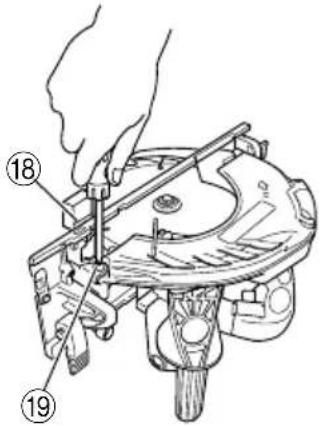
11
12(A)

12(B)

13

14

natural_image
Technical line drawing of a mechanical tool with a numbered label (26) pointing to a component on a workbench.15

natural_image
Technical line drawing of a mechanical device with no visible text or symbols16

17
18

19
20

| English | Deutsch Ελληνικά | Polski | ||
| 1 | Lumber Schnittholz Ξυλεία | Drewno | ||
| 2 | Base Grundplatte Bąση | Podstawa | ||
| 3 | Workbench Werkbank Πάνκος εργασίας | Stół roboczy | ||
| 4 | Saw blade Sägeblatt Πριονωτή λεπίδα | Ostrze piły | ||
| 5 | Handle Handgriff Λαβή | Uchwyt | ||
| 6 | Knob Stellknopf Kouμπί | Pokrętło | ||
| 7 | Riving knife Spaltkeil Διαχωριστικό μαχαίρι | Klin rozszczepiający | ||
| 8 | Flange bolt Flanschschraube Bīδα οδοντοτροχού | Śruba kołnierzowa | ||
| 9 | Lever Hebel | Μοχλός | Dźwignia | |
| 10 | Wing-bolt | Fügelschraube | Φτερωτό μπουλόνι | Śruba skrzydełkowa |
| 11 | Clamp lever Klemmhebel | Μοχλός σύσφίξης | Dźwignia zaciskowa | |
| 12 | Guide rail adapter | Führungsschienenadapter | Προσαρμογέας οδηγού σιδηροτροχιάς | Adaptor prowadnicy |
| 13 | Guide | Führung | Οδηγός | Prowadnica |
| 14 | Mounting screw | Befestigungsschraube | Ράβδος συναρμολόγησης | Śruba montażowa |
| 15 | Saw cover hinge | Scharnier Sägenabdeckung | Ρεζές καλύμματος πριονιού | Zawias osłony piły |
| 16 | Lower guard | Untere Schutzabdeckung | Κάτω προστατευτικό κάλυμμα | Osłona dolna |
| 17 | Saw cover Sägeblattdeckel | Κάλυμμα πριονιού | Pokrywa piły | |
| 18 | Wood chip | Holzspan | Ξύλινο γρέζι | Wiór |
| 19 | Parallelism adjustment screw | Parallelität-Einstellschraube | Βίδα παράλληλης ρύθμισης | Śruba regulacji równolegiej |
| 20 | Premarked line | Versetzt-Markierung | Προσημειωμένη γραμμή | Oznakowanie |
| 21 | Guide piece | Führungsstück | Οδηγητικό κομμάτι | Element prowadzący |
| 22 | Front scale when not inclined geneigt | Frontskala wenn nicht δεν βρίσκεται σε | Μπροστινή κλίμακα όταν κλίση | Podziałka przednia bez nachylenia |
| 23 | Front scale at 45° incline | Frontskala bei 45°-Neigung | Μπροστινή κλίμακα με κλίση 45° | Podziałka przednia ze 45-stopniowym nachleniem |
| 24 | M4 Screw M4 Schraube | M4 Bīδα | Śruba M4 | |
| 25 | Rail bar | Schienenstab | Ράβδος Σιδηροτροχιάς | Szyna prowadnicy |
| 26 | Guide rail | Führungsschiene | Οδηγός σιδηροτροχιάς | Prowadnica |
| 27 | Dust collector | Staubsauger | Συλλογέας σκόνης | Odpylacz |
| 28 | Head of bolt | Schraubenkopf | Κεφαλή βίδας | Łeb śruby |
| 29 | Lock lever Sperrhebel Moχλός κλειδώματος | Dźwignia blokady | ||
| 30 | Box wrench | Steckschlüssel | Μπουλονόκλειδο | Klucz nasadowy |
| 31 | Hexagonal-head bolt | Sechskantkopfschraube | Βίδα εξάγωνης κεφαλής | Śruba sześciokątna |
| 32 | Washer (A) Unterlegscheibe (A) | Ροδέλα (A) | Podkładka (A) | |
| 33 | Washer (B) Unterlegscheibe (B) | Ροδέλα (B) | Podkładka (B) | |
| 34 | Spindle | Achse | Άξονας | Wrzeciono |
| 35 | Wear limit | Verschleißgrenze | Όριο φθοράς | Granica zużycia |
| 36 | No. of carbon brush | Nr. der Kohlebürste | Αρ. Карβουνακιού | Numer szczotki węglowej |
| 37 | Square | Winkel | Γνώμονας | Kątownik |
| 38 | Slotted set screw | Schaftschraube | Βίδα με εγκοπή | Szczelinowa śrubamocująca |
| Magyar Čeština Türkçe Română | ||||
| 1 | Faanyag Dřevěné prkno | Kereste | Scândură | |
| 2 | Alap Základová deska | Taban/Alt kısım | Bază | |
| 3 | Munkaasztal Pracovní stůl | Çalışma tezgahı | Banc de lucru | |
| 4 | Fűrészlap Pilový kotouč | Testere bıçağı | Lamă fierăstrău | |
| 5 | Fogantyú Rukojeť | Sap | Mâner | |
| 6 | Gomb Otočná rukojeť | Tokmak düğmesi | Buton | |
| 7 | Hasítókés Štípací nůž | Yarma bıçağı | Cuțit de despicat | |
| 8 | Perem csavar Šroub příruby | Flanș civatası | Şurub cu flanşă | |
| 9 | Kar Páka | Kol | Manetă | |
| 10 | Szárnyascsavar Křídlový šroub | Kelebek civata | Şurub cu cap fluture | |
| 11 | Fogókar Páčka svorky | Sıkma kolu | Manetă de strîngere | |
| 12 | Vezető sín adapter Adaptér | vodicí kolejničky | Kılavuz ray adaptörü | Adaptor pentru șină de ghidare |
| 13 | Vezetőelem Vedení | Kılavuz | Ghidaj | |
| 14 | Emelőcsavar | Montážní šroub | Montaj vidası | Şurub de montare |
| 15 | Fűrészfedő zsanér | Závěs víka pily | Testere kapağı menteşesi | Balama de acoperire pînză |
| 16 | Alsó védőelem | Spodní ochranný kryt | Alt koruyucu | Protectție inferioară |
| 17 | A fűrész burkolata | Kryt pily | Testere kapağı | Protectție pînză |
| 18 | Fadarab Dřevěná tříska | Tahta yonga | Element lemn | |
| 19 | Párhuzamos beállító | Seřizovací šroub | Paralel ayar vidası | Şurub de ajustare paralelism |
| 20 | Előre megjelölt | Předznačený | Önceden işaretli | Linie premarcată |
| 21 | Vezető darab | Vodicí segment | Kılavuz parçası | Piesă de ghidare |
| 22 | Elülső skála megdöntés nélkül | Přední stupnice neskloněná | Eğimsiz ön ölçek | Scară frontală poziție ne-înclinată |
| 23 | Elülső skála 45°-os Přední stólésszögnél | stupnice skloněná v úhlu 45° | 45o eğimde ön ölçek | Scară frontală la înclinare 45° |
| 24 | M4 csavar | Šroub M4 | M4 Vida | Şurub M4 |
| 25 | Sínléc | Tyč kolejničky | Ray çubuğu | Bară șină |
| 26 | Vezető sín | Vodicí kolejnička | Kılavuz ray | Şină de ghidare |
| 27 | Porgyűjtő | Sběrač prachu | Toz toplayıcı | Colector de praf |
| 28 | Csavarfej Hlava šroubu | Civatanın kafası | Capul şurubului | |
| 29 | Rögzítőkar | Pojistná páka | Kilit kolu | Manetă de blocare |
| 30 | Dugókulcs | Nástrčný klíč | Lokma anahtarı | Cheie tubulară |
| 31 | Hatlapfejű csavar | Šroub se šestihrannou hlavou | Altigen başlı civata | Şurub cu cap hexagonal |
| 32 | Alátét (A) | Podložka (A) | Pul (A) | Şaibă (A) |
| 33 | Alátét (B) | Podložka (B) | Pul (B) | Şaibă (B) |
| 34 | Orsó | Vřeteno | Mil | Ax |
| 35 | Kopási határ Mez opotřebení | Yipranma limiti | Limită de uzură | |
| 36 | Szénkefék sz. Č. uhlíkového | kartáčku | Kömür fırça sayısı | Nr. periei de cărbune |
| 37 | Négyzet Čtyřhranný tvar | Kare | Echer | |
| 38 | Hasított hernyócsavar | Závitový šroub s drážkou v hlavě | Düz başlı vida | Şurub obișnuit |
Read all safety warnings and all instructions.
Failure to follow the warnings and instructions may result in electric shock, fire and/or serious injury.
Save all warnings and instructions for future reference.
The term "power tool" in the warnings refers to your mains-operated (corded) power tool or battery-operated (cordless) power tool.
1) Work area safety
a) Keep work area clean and well lit.
Cluttered or dark areas invite accidents.
b) Do not operate power tools in explosive atmospheres, such as in the presence of flammable liquids, gases or dust.
Power tools create sparks which may ignite the dust or fumes.
c) Keep children and bystanders away while operating a power tool.
Distractions can cause you to lose control.
2) Electrical safety
a) Power tool plugs must match the outlet.
Never modify the plug in any way.
Do not use any adapter plugs with earthed (grounded) power tools.
Unmodified plugs and matching outlets will reduce risk of electric shock.
b) Avoid body contact with earthed or grounded surfaces, such as pipes, radiators, ranges and refrigerators.
There is an increased risk of electric shock if your body is earthed or grounded.
c) Do not expose power tools to rain or wet conditions.
Water entering a power tool will increase the risk of electric shock.
d) Do not abuse the cord. Never use the cord for carrying, pulling or unplugging the power tool.
Keep cord away from heat, oil, sharp edges or moving parts.
Damaged or entangled cords increase the risk of electric shock.
e) When operating a power tool outdoors, use an extension cord suitable for outdoor use.
Use of a cord suitable for outdoor use reduces the risk of electric shock.
f) If operating a power tool in a damp location is unavoidable, use a residual current device (RCD) protected supply.
Use of an RCD reduces the risk of electric shock.
3) Personal safety
a) Stay alert, watch what you are doing and use common sense when operating a power tool.
Do not use a power tool while you are tired or under the influence of drugs, alcohol or medication.
A moment of inattention while operating power tools may result in serious personal injury.
b) Use personal protective equipment. Always wear eye protection.
Protective equipment such as dust mask, non-skid safety shoes, hard hat, or hearing protection used for appropriate conditions will reduce personal injuries.
c) Prevent unintentional starting. Ensure the switch is in the off-position before connecting to power source and/or battery pack, picking up or carrying the tool.
Carrying power tools with your finger on the switch or energising power tools that have the switch on invites accidents.
d) Remove any adjusting key or wrench before turning the power tool on.
A wrench or a key left attached to a rotating part of the power tool may result in personal injury.
e) Do not overreach. Keep proper footing and balance at all times.
This enables better control of the power tool in unexpected situations.
f) Dress properly. Do not wear loose clothing or jewellery. Keep your hair, clothing and gloves away from moving parts.
Loose clothes, jewellery or long hair can be caught in moving parts.
g) If devices are provided for the connection of dust extraction and collection facilities, ensure these are connected and properly used.
Use of dust collection can reduce dust related hazards.
4) Power tool use and care
a) Do not force the power tool. Use the correct power tool for your application.
The correct power tool will do the job better and safer at the rate for which it was designed.
b) Do not use the power tool if the switch does not turn it on and off.
Any power tool that cannot be controlled with the switch is dangerous and must be repaired.
c) Disconnect the plug from the power source and/or the battery pack from the power tool before making any adjustments, changing accessories, or storing power tools.
Such preventive safety measures reduce the risk of starting the power tool accidentally.
d) Store idle power tools out of the reach of children and do not allow persons unfamiliar with the power tool or these instructions to operate the power tool. Power tools are dangerous in the hands of untrained users.
e) Maintain power tools. Check for misalignment or binding of moving parts, breakage of parts and any other condition that may affect the power tool's operation.
If damaged, have the power tool repaired before use. Many accidents are caused by poorly maintained power tools.
f) Keep cutting tools sharp and clean.
Properly maintained cutting tools with sharp cutting edges are less likely to bind and are easier to control.
g) Use the power tool, accessories and tool bits etc. in accordance with these instructions, taking into account the working conditions and the work to be performed.
Use of the power tool for operations different from those intended could result in a hazardous situation.
5) Service
a) Have your power tool serviced by a qualified repair person using only identical replacement parts.
This will ensure that the safety of the power tool is maintained.
PRECAUTION
Keep children and infirm persons away.
When not in use, tools should be stored out of reach of children and infirm persons.
CIRCULAR SAW SAFETY WARNINGS
Cutting procedures
a) DANGER: Keep hands away from cutting area and the blade. Keep your second hand on auxiliary handle, or motor housing.
If both hands are holding the saw, they cannot be cut by the blade.
b) Do not reach underneath the workpiece.
The guard cannot protect you from the blade below the workpiece.
c) Adjust the cutting depth to the thickness of the workpiece.
Less than a full tooth of the blade teeth should be visible below the workpiece.
d) Never hold piece being cut in your hands or across your leg. Secure the workpiece to a stable platform.
It is important to support the work properly to minimize body exposure, blade binding, or loss of control.
e) Hold the power tool by insulated gripping surfaces only, when performing an operation where the cutting tool may contact hidden wiring or its own cord.
Contact with a "live" wire will also make exposed metal parts of the power tool "live" and could give the operator an electric shock.
f) When ripping always use a rip fence or straight edge guide.
This improves the accuracy of cut and reduces the chance of blade binding.
g) Always use blades with correct size and shape (diamond versus round) of arbour holes.
Blades that do not match the mounting hardware of the saw will run eccentrically, causing loss of control.
h) Never use damaged or incorrect blade washers or bolt.
The blade washers and bolt were specially designed for your saw, for optimum performance and safety of operation.
Kickback causes and related warnings
- kickback is a sudden reaction to a pinched, bound or misaligned saw blade, causing an uncontrolled saw to lift up and out of the workpiece toward the operator;
- when the blade is pinched or bound tightly by the kerf closing down, the blade stalls and the motor reaction drives the unit rapidly back toward the operator;
- if the blade becomes twisted or misaligned in the cut, the teeth at the back edge of the blade can dig into the top surface of the wood causing the blade to climb out of the kerf and jump back toward the operator.
Kickback is the result of saw misuse and/or incorrect operating procedures or conditions and can be avoided by taking proper precautions as given below.
a) Maintain a firm grip with both hands on the saw and position your arms to resist kickback forces.
Position your body to either side of the blade, but not in line with the blade.
Kickback could cause the saw to jump backwards, but kickback forces can be controlled by the operator, if proper precautions are taken.
b) When blade is binding, or when interrupting a cut for any reason, release the trigger and hold the saw motionless in the material until the blade comes to a complete stop.
Never attempt to remove the saw from the work or pull the saw backward while the blade is in motion or kickback may occur.
Investigate and take corrective actions to eliminate the cause of blade binding.
c) When restarting a saw in the workpiece, centre the saw blade in the kerf and check that saw teeth are not engaged into the material.
If saw blade is binding, it may walk up or kickback from the workpiece as the saw is restarted.
d) Support large panels to minimise the risk of blade pinching and kickback.
Large panels tend to sag under their own weight. Supports must be placed under the panel on both sides, near the line of cut and near the edge of the panel.
e) Do not use dull or damaged blades.
Unsharpened or improperly set blades produce narrow kerf causing excessive friction, blade binding and kickback.
f) Blade depth and bevel adjusting locking levers must be tight and secure before making cut.
If blade adjustment shifts while cutting, it may cause binding and kickback.
g) Use extra caution when sawing into existing walls or other blind areas.
The protruding blade may cut objects that can cause kickback.
Lower guard function
a) Check lower guard for proper closing before each use. Do not operate the saw if lower guard does not move freely and close instantly. Never clamp or tie the lower guard into the open position.
If saw is accidentally dropped, lower guard may be bent.
Raise the lower guard with the retracting handle and make sure it moves freely and does not touch the blade or any other part, in all angles and depths of cut.
b) Check the operation of the lower guard spring. If the guard and the spring are not operating properly, they must be serviced before use.
Lower guard may operate sluggishly due to damaged parts, gummy deposits, or a build-up of debris.
c) Lower guard may be retracted manually only for special cuts such as "plunge cuts" and "compound cuts". Raise lower guard by retracting handle and as soon as blade enters the material, the lower guard must be released.
For all other sawing, the lower guard should operate automatically.
d) Always observe that the lower guard is covering the blade before placing saw down on bench or floor.
An unprotected, coasting blade will cause the saw to walk backwards, cutting whatever is in its path. Be aware of the time it takes for the blade to stop after switch is released.
Riving knife function
a) Use the appropriate saw blade for the riving knife.
For the riving knife to function, the body of the blade must be thinner than the riving knife and the cutting width of the blade must be wider than the thickness of the riving knife.
b) Adjust the riving knife as described in this instruction manual.
Incorrect spacing, positioning and alignment can make the riving knife ineffective in preventing kickback.
c) Always use the riving knife except when plunge cutting.
Riving knife must be replaced after plunge cutting. Riving knife causes interference during plunge cutting and can create kickback.
d) For the riving knife to work, it must be engaged in the workpiece.
The riving knife is ineffective in preventing kickback during short cuts.
e) Do not operate the saw if riving knife is bent.
Even a light interference can slow the closing rate of a guard.
PRECAUTIONS ON USING CIRCULAR SAW
- Do not use saw blades which are deformed or cracked.
- Do not use saw blades made of high speed steel.
- Do not use saw blades which do not comply with the characteristics specified in these instructions.
- Do not stop the saw blades by lateral pressure on the disc.
- Always keep the saw blades sharp.
- Ensure that the lower guard smoothly and freely.
-
Never use the circular saw with its lower guard fixed in the open position.
-
Ensure that the retraction mechanism of the guard system operates correctly.
- The saw blades body must be thinner than the riving knife and the width of cut, or kerf (with teeth set) must be greater than the thickness of the riving knife.
- Never operate the circular saw with the saw blade turned upward or to the side.
- Ensure that the material is free of foreign matters such as nails.
- The riving knife should always be used except when plunging in the middle of the workpiece.
- For models C6UY and C6BUY, the saw blades range should be from 165 mm to 162 mm. For models C7UY and C7BUY, the saw blades range should be from 190 mm to 185 mm.
- For models C6BUY and C7BUY, be careful of brake kickback.
C6BUY and C7BUY models features an electric brake that functions when the switch is released. As there is some kickback when the brake functions, be sure to hold the main body securely. - Sparks can sometimes appear caused by braking operation when the switch is turned off since C6BUY and C7BUY models employ electric brakes. Be informed, however, that this phenomenon is not a machine trouble.
- For models C6BUY and C7BUY, when the brake becomes ineffective, replace the carbon brushes with new ones.
- Disconnect the plug from the receptacle before carrying out any adjustment, servicing or maintenance.
SPECIFICATIONS
| Model C6UY C6BUY C7UY C7BUY | |||||
| Voltage (by areas)* | 230 V ~ | ||||
| Cutting Depth | 90° 66 mm 78 mm | ||||
| 45° 46 mm 55 mm | |||||
| Power Input* | 1300 W | ||||
| No-Load Speed | 5500 min ^-1 | ||||
| Weight (without cord) 3.8 kg 4.2 kg | |||||
*Be sure to check the nameplate on product as it is subject to change by areas.
STANDARD ACCESSORIES
(1) Saw Blade (mounted on tool) 1
(Dia. 165 mm ....C6UY, C6BUY) Dia. 190 mm ....C7UY, C7BUY)
(2) Hex. bar wrench 1
(3) Guide ...... 1
(4) Box wrench 1
(5) Dust collector 1
(6) M4 screw 1
(7) Guide Rail Adapter 1
Standard accessories are subject to change without notice.
APPLICATION
Cutting various types of wood.
PRIOR TO OPERATION
1. Power source
Ensure that the power source to be utilized conforms to the power requirements specified on the product nameplate.
2. Power switch
Ensure that the power switch is in the OFF position. If the plug is connected to a receptacle while the power switch is in the ON position, the power tool will start operating immediately, which could cause a serious accident.
3. Extension cord
When the work area is removed from the power source, use an extension cord of sufficient thickness and rated capacity. The extension cord should be kept as short as practicable.
4. Prepare a wooden workbench (Fig. 1)
Since the saw blade will extend beyond the lower surface of the lumber, place the lumber on a workbench when cutting. If a square block is utilized as a workbench, select level ground to ensure it is properly stabilized. An unstable workbench will result in hazardous operation.
CAUTION
To avoid possible accident, always ensure that the portion of lumber remaining after cutting is securely anchored or held in position.
ADJUSTING THE SAW PRIOR TO USE
1. Adjusting the cutting depth
As shown in Fig. 2, hold the handle with one hand while loosening the knob with the other.
The cutting depth can be adjusted by moving the base to the desired position. In such manner adjust the cutting depth and then securely retighten the knob.
2. Adjusting the riving knife
First tighten the knob and firmly secure the saw cover. (Fig. 2)
Loosen the flange bolt (2 pcs.) used to clamp the riving knife, adjust the riving knife so that the distance between the riving knife and the rim of the blade is not more than 5 mm, and the rim of the blade does not extend more than 5 mm beyond the lowest edge of the riving knife (Fig. 3) and securely retighten the flange bolt (2 pcs.).
3. Adjusting the angle of inclination
As shown in Fig. 4 (A), Fig. 4 (B) by loosening the lever on the incline gauge and the wing-bolt on the base, the saw blade may be inclined to a maximum angle of 45^ in relation to the base. After having completed the adjustment, reconfirm that the lever and the wing-bolt are firmly tightened.
4. Regulating the guide
Loosen the clamp lever at the front and back of the base and detach the guide rail adapter from the main unit. (Fig. 5)
NOTE
Be informed that for some products the knob and the guide rail adapter can collide when the guide rail adapter is removed. Under such a circumstance, remove the guide rail adapter after slightly reducing the cutting depth of the body. (Fig. 6)
The cutting position can be regulated by moving the guide to the left or right after loosening its clamp lever. The guide may be mounted on either the right or left side of the tool. (Fig. 7)
5. Fine tuning of parallelism
It is possible to fine-tune the parallelism of the saw blade to the base using the parallelism adjustment screw.
Adjustment has already been made at the time of shipment from the factory. However, in the unlikely event of parallelism being faulty, adjust as follows.
(1) Unfasten only the mounting screws of the saw cover hinge portion (Fig. 8).
(2) Retract the lower guard into the saw cover.
(3) Insert wood chip in the rear side of the saw blade base, and mark the position on the base (Fig. 9).
(4) Move the marked wood chip to the front of the base, and turn the parallelism adjustment screw so that the marking corresponds to the base side (Fig. 10).
(5) After adjustment, fasten the mounting screws tightly in place.
NOTE
Parallelism may be slightly faulty if the cutting depth is adjusted after parallelism adjustment.
6. Adjusting the guide piece
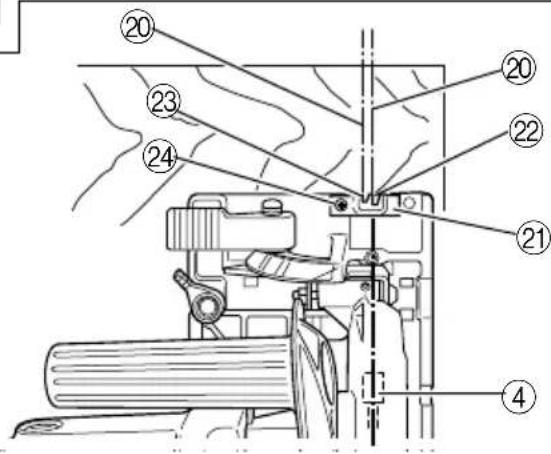
On the circular saw, it is possible to make fine adjustment of the fixing position of the guide piece, where the saw blade and the premarked line are to be aligned.
When the saw is shipped from the factory, the linear portion of a front scale on the guide piece is aligned with the central position of the saw blade (Fig. 11).
Loosen the fixed M4 screw on the guide piece, should the fixing position be wrong, and make necessary adjustment of the position.
7. Using the guide rail
Pass the guide rail adapter through the base square socket, and clamp the clamp lever at the position where the guide rail adapter and the surface of the base side come in contact. (Fig. 5)
NOTE
Be informed that for some products the knob and the guide rail adapter can collide when the guide rail adapter is removed. Under such a circumstance, remove the guide rail adapter after slightly reducing the cutting depth of the body. (Fig. 6)
(1) Loosen the wing bolt. Adjust the position of the rail bar according to the guide rail to be used, and fix it with the wing bolt. (Fig. 13)
(2) Place the body on the guide rail so that the protrusion of the guide rail can fit into the groove of the guide rail adapter. (Fig. 14)
(3) Loosen the clamp lever, adjust the position of the saw blade, and then clamp the clamp lever again.
(4) In this condition, you can start off cutting operation.
NOTE
When performing cutting operation using the guide rail, remember that the cutting depth decreases as the thickness of the guide rail increases.
○This guide rail adapter can be used for the guide rails of BOSCH, FESTO, and MAKITA.
○When the guide rail is used at a 45 degree inclination, the position of the saw blade does not agree with the notch provided on the tip of the base.
8. Using the dust collector
To use the vacuum cleaner to gather up saw dust, attach the suction hose to the dust collector which is attached to the main unit by M4 screw. (Fig. 15)
9. Adjusting the position of the clamp lever
Depressing the clamp lever disengages it from the bolt head, leaving it free to rotate.
After securely fixing the guide and the guide rail, depress the clamp lever and rotate it to a position in which it will not interfere with cutting operation. (Fig. 16)
CUTTING PROCEDURES
- Place the base on the material, then align the premarked line and the sawblade with the guide piece front scale section at the front of the base (Fig. 11).
When the base is not slanted, use the large cutout as the guide (Fig. 11, Fig. 12 (A)).
If the base is slanted (45 degrees), use the small front scale as the guide (Fig. 11, Fig. 12 (B)).
- Ensure that the switch is turned to the ON position before the saw blade comes in contact with the lumber. The switch is turned ON when the trigger is squeezed; and OFF when the trigger is released.
- Moving the saw straight at a constant speed will produce optimum cutting.
CAUTIONS
Prior to cutting operation, make sure the material you are going to cut. If the material to be cut is expected to generate harmful / toxic dusts, make sure the dust bag or appropriate dust extraction system is connected with dust outlet tightly.
Wear the dust mask additionally, if available.
A coating of PFTE is applied to the bases. Be careful not to press too hard on the unit body since this tends to place a heavy load on the motor. Using a gentle pressure will make the piece slide easier and allow cutting with less force. Trying to cut wood that is covered with hard particle material such as sand or metal chips tends to easily scratch damage the surface coating so use caution.
Before starting to saw, ensure that the saw blade has reached full speed revolution.
- Should the saw blade be stopped or made an abnormal noise during operation, turn off the switch immediately.
○Always take care in preventing the power cord from coming near the revolving saw blade.
○Using the circular saw with the saw blade facing upwards or sideways is very hazardous. Such uncommon applications should be avoided.
○When cutting materials, always wear protective glasses.
When finished with a job, pull out the plug from the receptacle.
MOUNTING AND DISMOUNTING THE SAW BLADE
CAUTION
To avoid serious accident, ensure the switch is in the OFF position, and the power source is disconnected.
1. Dismounting the saw blade
(1) Loosen the knob and slightly reduce the cutting depth from maximum. (Fig. 2)
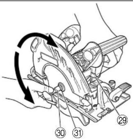
(2) Place the Circular Saw as shown in Fig. 17.
(3) Depress the lock lever, lock the spindle, and remove the hexagonal-head bolt with the box wrench.
(4) While holding the lower guard lever to keep the lower guard fully retracted into the saw cover, remove the saw blade.
2. Mounting the Saw Blade
(1) Loosen the knob and slightly reduce the cutting depth from maximum. (Fig. 2)
(2) Thoroughly remove any sawdust which has accumulated on the spindle, bolt and washers.
(3) As shown in Fig. 18, the side of Washer (A) with a projected center the same diameter as the inner diameter of the saw blade and the concave side of Washer (B) must be fitted to the saw blade sides.
(4) To assure proper rotation direction of the saw blade, the arrow direction on the saw blade must coincide with the arrow direction on the saw cover.
(5) Using the fingers, tighten the hexagonal-head bolt retaining the saw blade as much as possible. Then depress the lock lever, lock the spindle, and thoroughly tighten the bolt.
CAUTION
After having attached the saw blade, reconfirm that the lock lever is firmly secured in the prescribed position.
MAINTENANCE AND INSPECTION
1. Inspecting the saw blade
Since use of a dull saw blade will degrade efficiency and cause possible motor malfunction, sharpen or replace the saw blade as soon as abrasion is noted.
2. Inspecting the mounting screws
Regularly inspect all mounting screws and ensure that they are properly tightened. Should any of the screws be loose, retighten them immediately. Failure to do so could result in serious hazard.
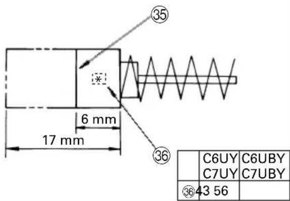
3. Inspecting the carbon brushes (Fig. 19)
The motor employs carbon brushes which are consumable parts. Since an excessively worn carbon brush can result in motor trouble, replace the carbon brushes with new ones having the same carbon brush No. shown in the figure when it becomes worn to or near the "wear limit". In addition, always keep carbon brushes clean and ensue that they slide freely within the brush holders.
CAUTION
○ When replacing the new carbon brushes, always use genuine HiKOKI carbon brushes with the number specified in the drawing.
☐ For models C6BUY and C7BUY, the brake may not work if other than the specified carbon brushes are used.
When the brake becomes ineffective, replace the carbon brushes with new ones.
4. Replacing carbon brushes
Disassemble the brush caps with a slotted-head screwdriver. The carbon brushes can then be easily removed.
5. Maintenance of the motor
The motor unit winding is the very "heart" of the power tool.
Exercise due care to ensure the winding does not become damaged and/or wet with oil or water.
6. Adjusting the base and saw blade to maintain perpendicularity
The angle between the base and the saw blade has been adjusted to 90^ , however should this perpendicularity be lost for some reason, adjust in the following manner:
(1) Turn the base face up (Fig. 20) and loosen the lever and wing-bolt. (Fig. 4 (A), Fig. 4 (B))
(2) Apply a square to the base and the saw blade and turning the slotted set screw with a slotted-head screwdriver, shift the position of the base to produce the desired right angle.
7. Maintenance of the lower guard
For safe and proper working, always keep the machine and ventilation slots clean. The lower guard must always be able to more freely and retract automatically. Therefore, always keep the area around the lower guard clean. Remove dust and chips by blowing out with compressed air or with a brush.
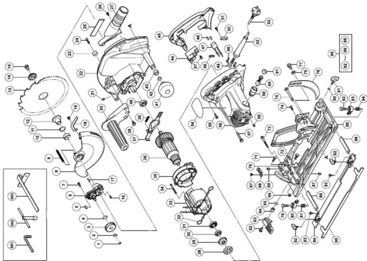
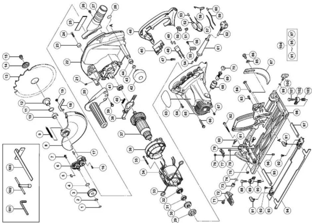
8. Service parts list
CAUTION
Repair, modification and inspection of HiKOKI Power Tools must be carried out by an HiKOKI Authorized Service Center.
This Parts List will be helpful if presented with the tool to the HiKOKI Authorized Service Center when requesting repair or other maintenance.
In the operation and maintenance of power tools, the safety regulations and standards prescribed in each country must be observed.
MODIFICATIONS
HiKOKI Power Tools are constantly being improved and modified to incorporate the latest technological advancements.
Accordingly, some parts may be changed without prior notice.
GUARANTEE
We guarantee HiKOKI Power Tools in accordance with statutory/country specific regulation. This guarantee does not cover defects or damage due to misuse, abuse, or normal wear and tear. In case of complaint, please send the Power Tool, undismantled, with the GUARANTEE CERTIFICATE found at the end of this Handling instruction, to a HiKOKI Authorized Service Center.
NOTE
Due to HiKOKI's continuing program of research and development, the specifications herein are subject to change without prior notice.
Information concerning airborne noise and vibration
The measured values were determined according to EN 60745 and declared in accordance with ISO 4871.
C6UY • C6BUY
Measured A-weighted sound power level: 101 dB(A)
Measured A-weighted sound pressure level: 90 dB(A)
Uncertainty KpA: 3 dB(A)
C7UY • C7BUY
Measured A-weighted sound power level: 106 dB(A)
Measured A-weighted sound pressure level: 95 dB(A)
Uncertainty KpA: 3 dB(A)
Wear hearing protection.
Vibration total values (triax vector sum) determined according to EN60745.
Cutting chipboard:
Vibration emission value a_h = 2.4 m/s^2
Uncertainty K = 1.5 m/s ^4
The declared vibration total value has been measured in accordance with a standard test method and may be used for comparing one tool with another.
It may also be used in a preliminary assessment of exposure.
WARNING
○The vibration emission during actual use of the power tool can differ from the declared total value depending on the ways in which the tool is used.
○Identify safety measures to protect the operator that are based on an estimation of exposure in the actual conditions of use (taking account of all parts of the operating cycle such as the times when the tool is switched off and when it is running idle in addition to the trigger time).
C6BUY
| Item No. | Part Name Q'TY | |
| 55 | CORD CLIP | 1 |
| 56 | TAPPING SCREW (W/FLANGE) D4×16 | 2 |
| 57 | INTERNAL WIRE | 1 |
| 58 | WIRE CLAMP | 1 |
| 59 | INTERNAL WIRE | 1 |
| 60 | TUBE (D) 1 | |
| 61 | CORD ARMOR | 1 |
| 62 | CORD | 1 |
| 63 | NAME PLATE | 1 |
| 64 | TAPPING SCREW (W/FLANGE) D4×20 | 4 |
| 65 | HOUSING ASS'Y | 1 |
| 66 | MACHINE SCREW (W/WASHERS) M5×40 | 3 |
| 67 | HEX. SOCKET SET SCREW M5×8 | 2 |
| 68 | BRUSH HOLDER | 2 |
| 69 | CARBON BRUSH | 2 |
| 70 | BRUSH CAP 2 | |
| 71 | SEAL LOCK SCREW (W/SP. WASHERS) M6×14 | 1 |
| 72 | LEVER (A) | 1 |
| 73 | LOCK NUT | 1 |
| 74 | WASHER 1 | |
| 75 | U-NUT M5 | 1 |
| 76 | MACHINE SCREW (W/SP. WASHER) M4 | 1 |
| 77 | GUIDE PIECE | 1 |
| 78 | SEAL LOCK HEX. SOCKET SET SCREW M5×6 | 1 |
| 79 | BEVEL PLATE | 1 |
| 80 | STEP PIN D6×13 | 1 |
| 81 | BOLT (SQUARE) M6×20 | 1 |
| 82 | ADJUSTING SCREW (A) | 1 |
| 83 | SPECIAL SCREW M6 1 | |
| 84 | DIAGONAL BOLT M8 | 1 |
| 85 | BOLT WASHER M6 | 2 |
| 86 | BOLT (W/FLANGE) M6 | 2 |
| 87 | RIVING KNIFE | 1 |
| 88 | BOLT M6×10 1 | |
| 89 | CLAMP LEVER | 1 |
| 90 | SPRING(B) | 1 |
| 91 | WING BOLT M6×12 | 2 |
| 92 | MACHINE SCREW (W/SP. WASHER) M5×12 | 2 |
| 93 | GUIDE RAIL ADAPTER | 1 |
| 94 | GUIDE RAIL PLATE | 1 |
| 95 | GUIDE BAR | 1 |
| 96 | SLOTTED HD. SET SCREW (SEAL LOCK) M6×6 | 1 |
| 97 | GUIDE BAR | 1 |
| 98 | BASE ASS'Y | 1 |
| 99 | WASHER M6 | 1 |
| 100 | WING BOLT M6×17 | 1 |
| 101 | BOLT M6×10 1 | |
| 102 | CLAMP LEVER | 1 |
| 103 | SPRING (B) | 1 |
| 104 | GUIDE RAIL ASS'Y | 1 |
| 501 | HEX. BAR WRENCH 2.5MM | 1 |
| 502 | BOX WRENCH 10MM | 1 |
| 503 | GUIDE | 1 |
| Item No. | Part Name Q'TY | |
| 1 WASHER 1 | ||
| 2 RETAINING RING FOR D11 SHAFT 1 | ||
| 3 FIRST GEAR 1 | ||
| 4 O-RING 1 | ||
| 5 FEATHER KEY 4×4×10 1 | ||
| 6 BEARING HOLDER ASS'Y 1 | ||
| 7 | MACHINE SCREW (W/SP. WASHER) M4 | 3 |
| 8 LOWER GUARD 1 | ||
| 9 RETURN SPRING (A) 1 | ||
| 10 BUSHING 1 | ||
| 11 RETAINING RING FOR D22 SHAFT 1 | ||
| 12 WASHER (A) 1 | ||
| 13 TCT SAW BLADE 165 MM 1 | ||
| 14 WASHER(B) 1 | ||
| 15 BOLT (W/WASHER) M7×17.5 1 | ||
| 16 MACHINE SCREW M3 | 3 | |
| 17 NEEDLE ROLLER | 1 | |
| 18 LEVER | 1 | |
| 19 | MACHINE SCREW (W/SP. WASHER) M4×8 | 1 |
| 20 SIDE HANDLE | 1 | |
| 21 HEX. SOCKET SET SCREW M5×6 | 1 | |
| 22 GEAR COVER | 1 | |
| 23 CUSHION 1 | ||
| 24 FLAT HD. SCREW M6×20 | 1 | |
| 25 | BRAND PLATE | 1 |
| 26 | MACHINE SCREW (W/WASHERS) M4×12 | 1 |
| 27 DUST COLLECTOR | 1 | |
| 28 NAME PLATE (BRAKE) | 1 | |
| 29 RUBBER BUSHING | 1 | |
| 30 BEARING BUSHING | 1 | |
| 31 BALL BEARING 608VVC2PS2L | 1 | |
| 32 DUST SEAL | 1 | |
| 33 BRUSH TERMINAL | 2 | |
| 34 STATOR ASS'Y | 1 | |
| 35 HEX. HD. TAPPING SCREW D5×55 | 2 | |
| 36 FAN GUIDE | 1 | |
| 37 ARMATURE 1 | ||
| 38 LOCK LEVER 1 | ||
| 39 | MACHINE SCREW (W/WASHERS) M5×16 | 3 |
| 40 SPRING (A) | 1 | |
| 41 BALL BEARING 6000VVCMPS2L | 1 | |
| 42 KNOB | 1 | |
| 43 O-RING 1 | ||
| 44 SLEEVE | 1 | |
| 45 SWITCH (B) | 1 | |
| 46 HANDLE COVER | 1 | |
| 47 TERMINAL M4.0 | 1 | |
| 48 NOISE SUPPRESSOR | 1 | |
| 49 TUBE (D) | 2 | |
| 50 PILLAR TERMINAL | 1 | |
| 51 CONNECTOR 50092 | 1 | |
| 52 RESISTOR | 1 | |
| 53 TUBE (D) | 1 | |
| 54 TUBE (D) | 2 | |

C7UY
| Item No. | Part Name Q'TY | |
| 51 | TAPPING SCREW (W/FLANGE) D4×16 | 2 |
| 52 | CORD ARMOR | 1 |
| 53 | CORD | 1 |
| 54 | NAME PLATE | 1 |
| 55 | TAPPING SCREW (W/FLANGE) D4×20 | 4 |
| 56 | HOUSING ASS'Y | 1 |
| 57 | MACHINE SCREW (W/WASHERS) M5×40 | 3 |
| 58 | HEX. SOCKET SET SCREW M5×8 | 2 |
| 59 | BRUSH HOLDER | 2 |
| 60 | CARBON BRUSH | 2 |
| 61 | BRUSH CAP | 2 |
| 62 | SEAL LOCK SCREW (W/SP. WASHERS) M6×14 | 1 |
| 63 | LEVER (A) | 1 |
| 64 | LOCK NUT | 1 |
| 65 | WASHER 1 | |
| 66 | U-NUT M5 | 1 |
| 67 | MACHINE SCREW (W/SP. WASHER) M4 | 1 |
| 68 | GUIDE PIECE | 1 |
| 69 | SEAL LOCK HEX. SOCKET SET SCREW M5×6 | 1 |
| 70 | BEVEL PLATE | 1 |
| 71 | STEP PIN D6×13 | 1 |
| 72 | BOLT (SQUARE) M6×20 | 1 |
| 73 | ADJUSTING SCREW (A) | 1 |
| 74 | SPECIAL SCREW M6 | 1 |
| 75 | DIAGONAL BOLT M8 | 1 |
| 76 | BOLT WASHER M6 | 2 |
| 77 | BOLT (W/FLANGE) M6 | 2 |
| 78 | RIVING KNIFE | 1 |
| 79 | BOLT M6×10 1 | |
| 80 | CLAMP LEVER | 1 |
| 81 | SPRING(B) | 1 |
| 82 | WING BOLT M6×12 | 2 |
| 83 | MACHINE SCREW (W/SP. WASHER) M5×12 | 2 |
| 84 | GUIDE RAIL ADAPTER | 1 |
| 85 | GUIDE RAIL PLATE | 1 |
| 86 | GUIDE BAR | 1 |
| 87 | SLOTTED HD. SET SCREW (SEAL LOCK) M6×6 | 1 |
| 88 | GUIDE BAR | 1 |
| 89 | BASE ASS'Y | 1 |
| 90 | WASHER M6 | 1 |
| 91 | WING BOLT M6×17 | 1 |
| 92 | BOLT M6×10 1 | |
| 93 | CLAMP LEVER | 1 |
| 94 | SPRING (B) | 1 |
| 95 | GUIDE RAIL ASS'Y | 1 |
| 96 | TERMINAL | 2 |
| 97 | MACHINE SCREW (W/WASHER) M3.5×6 | 4 |
| 501 | HEX. BAR WRENCH 2.5MM | 1 |
| 502 | BOX WRENCH 10MM | 1 |
| 503 | GUIDE | 1 |
| Item No. | Part Name Q'TY | |
| 1 W | ASHER 1 | |
| 2 RETAINING RING FOR D11 SHAFT 1 | ||
| 3 FIRST GEAR 1 | ||
| 4 O-RING 1 | ||
| 5 FEATHER KEY 4×4×10 1 | ||
| 6 BEARING HOLDER ASS'Y 1 | ||
| 7 | MACHINE SCREW (W/SP. WASHER) M4 | 3 |
| 8 LOWER GUARD 1 | ||
| 9 RETURN SPRING (A) 1 | ||
| 10 BUSHING 1 | ||
| 11 RETAINING RING FOR D22 SHAFT 1 | ||
| 12 WASHER (A) 1 | ||
| 13 TCT SAW BLADE 190 MM 1 | ||
| 14 WASHER(B) 1 | ||
| 15 BOLT (W/WASHER) M7×17.5 1 | ||
| 16 MACHINE SCREW M3 | 3 | |
| 17 NEEDLE ROLLER | 1 | |
| 18 LEVER | 1 | |
| 19 | MACHINE SCREW (W/SP. WASHER) M4 ×8 | 1 |
| 20 SIDE HANDLE | 1 | |
| 21 HEX. SOCKET SET SCREW M5×6 | 1 | |
| 22 GEAR COVER | 1 | |
| 23 CUSHION 1 | ||
| 24 FLAT HD. SCREW M6×20 | 1 | |
| 25 BRAND PLATE | 1 | |
| 26 MACHINE SCREW (W/WASHERS) M4×12 | 1 | |
| 27 DUST COLLECTOR | 1 | |
| 28 RUBBER BUSHING | 1 | |
| 29 BEARING BUSHING | 1 | |
| 30 BALL BEARING 608VVC2PS2L | 1 | |
| 31 DUST SEAL | 1 | |
| 32 BRUSH TERMINAL | 2 | |
| 33 STATOR ASS'Y | 1 | |
| 34 HEX. HD. TAPPING SCREW D5×55 | 2 | |
| 35 FAN GUIDE | 1 | |
| 36 ARMATURE 1 | ||
| 37 LOCK LEVER 1 | ||
| 38 | MACHINE SCREW (W/WASHERS) M5×16 | 3 |
| 39 SPRING (A) | 1 | |
| 40 BALL BEARING 6000VVCMPS2L | 1 | |
| 41 KNOB | 1 | |
| 42 O-RING 1 | ||
| 43 SLEEVE | 1 | |
| 44 SWITCH | 1 | |
| 45 HANDLE COVER | 1 | |
| 46 TERMINAL M4.0 | 1 | |
| 47 NOISE SUPPRESSOR | 1 | |
| 48 TUBE (D) | 2 | |
| 49 TUBE (D) | 2 | |
| 50 CORD CLIP | 1 | |
C7BUY
| Item No. | Part Name Q'TY | |
| 55 | ORD CLIP | 1 |
| 56 | TAPPING SCREW (W/FLANGE) D4×16 | 2 |
| 57 | INTERNAL WIRE | 1 |
| 58 | WIRE CLAMP | 1 |
| 59 | INTERNAL WIRE | 1 |
| 60 | TUBE (D) 1 | |
| 61 | CORD ARMOR | 1 |
| 62 | CORD | 1 |
| 63 | NAME PLATE | 1 |
| 64 | TAPPING SCREW (W/FLANGE) D4×20 | 4 |
| 65 | HOUSING ASS'Y | 1 |
| 66 | MACHINE SCREW (W/WASHERS) M5×40 | 3 |
| 67 | HEX. SOCKET SET SCREW M5×8 | 2 |
| 68 | BRUSH HOLDER | 2 |
| 69 | CARBON BRUSH | 2 |
| 70 | BRUSH CAP 2 | |
| 71 | SEAL LOCK SCREW (W/SP. WASHERS) M6×14 | 1 |
| 72 | LEVER (A) | 1 |
| 73 | LOCK NUT | 1 |
| 74 | WASHER 1 | |
| 75 | U-NUT M5 | 1 |
| 76 | MACHINE SCREW (W/SP. WASHER) M4 | 1 |
| 77 | GUIDE PIECE | 1 |
| 78 | SEAL LOCK HEX. SOCKET SET SCREW M5×6 | 1 |
| 79 | BEVEL PLATE | 1 |
| 80 | STEP PIN D6×13 | 1 |
| 81 | BOLT (SQUARE) M6×20 | 1 |
| 82 | ADJUSTING SCREW (A) | 1 |
| 83 | SPECIAL SCREW M6 1 | |
| 84 | DIAGONAL BOLT M8 | 1 |
| 85 | BOLT WASHER M6 | 2 |
| 86 | BOLT (W/FLANGE) M6 | 2 |
| 87 | RIVING KNIFE | 1 |
| 88 | BOLT M6×10 1 | |
| 89 | CLAMP LEVER | 1 |
| 90 | SPRING(B) | 1 |
| 91 | WING BOLT M6×12 | 2 |
| 92 | MACHINE SCREW (W/SP. WASHER) M5×12 | 2 |
| 93 | GUIDE RAIL ADAPTER | 1 |
| 94 | GUIDE RAIL PLATE | 1 |
| 95 | GUIDE BAR | 1 |
| 96 | SLOTTED HD. SET SCREW (SEAL LOCK) M6×6 | 1 |
| 97 | GUIDE BAR | 1 |
| 98 | BASE ASS'Y | 1 |
| 99 | WASHER M6 | 1 |
| 100 | WING BOLT M6×17 | 1 |
| 101 | BOLT M6×10 1 | |
| 102 | CLAMP LEVER | 1 |
| 103 | SPRING (B) | 1 |
| 104 | GUIDE RAIL ASS'Y | 1 |
| 501 | HEX. BAR WRENCH 2.5MM | 1 |
| 502 | BOX WRENCH 10MM | 1 |
| 503 | GUIDE | 1 |
| Item No. | Part Name Q'TY | |
| 1 WASHER 1 | ||
| 2 RETAINING RING FOR D11 SHAFT 1 | ||
| 3 FIRST GEAR 1 | ||
| 4 O-RING 1 | ||
| 5 FEATHER KEY 4×4×10 1 | ||
| 6 BEARING HOLDER ASS'Y 1 | ||
| 7 | MACHINE SCREW (W/SP. WASHER) M4 | 3 |
| 8 LOWER GUARD 1 | ||
| 9 RETURN SPRING (A) 1 | ||
| 10 BUSHING 1 | ||
| 11 RETAINING RING FOR D22 SHAFT 1 | ||
| 12 WASHER (A) 1 | ||
| 13 TCT SAW BLADE 190 MM 1 | ||
| 14 WASHER(B) 1 | ||
| 15 BOLT (W/WASHER) M7×17.5 1 | ||
| 16 MACHINE SCREW M3 | 3 | |
| 17 NEEDLE ROLLER | 1 | |
| 18 LEVER | 1 | |
| 19 | MACHINE SCREW (W/SP. WASHER) M4×8 | 1 |
| 20 SIDE HANDLE | 1 | |
| 21 HEX. SOCKET SET SCREW M5×6 | 1 | |
| 22 GEAR COVER | 1 | |
| 23 CUSHION 1 | ||
| 24 FLAT HD. SCREW M6×20 | 1 | |
| 25 BRAND PLATE | 1 | |
| 26 MACHINE SCREW (W/WASHERS) M4×12 | 1 | |
| 27 DUST COLLECTOR | 1 | |
| 28 NAME PLATE (BRAKE) | 1 | |
| 29 RUBBER BUSHING | 1 | |
| 30 BEARING BUSHING | 1 | |
| 31 BALL BEARING 608VVC2PS2L | 1 | |
| 32 DUST SEAL | 1 | |
| 33 BRUSH TERMINAL | 2 | |
| 34 STATOR ASS'Y | 1 | |
| 35 HEX. HD. TAPPING SCREW D5×55 | 2 | |
| 36 FAN GUIDE | 1 | |
| 37 ARMATURE 1 | ||
| 38 LOCK LEVER 1 | ||
| 39 MACHINE SCREW (W/WASHERS) M5×16 | 3 | |
| 40 SPRING (A) | 1 | |
| 41 BALL BEARING 6000VVCMPS2L | 1 | |
| 42 KNOB | 1 | |
| 43 O-RING 1 | ||
| 44 SLEEVE | 1 | |
| 45 SWITCH (B) | 1 | |
| 46 HANDLE COVER | 1 | |
| 47 TERMINAL M4.0 | 1 | |
| 48 NOISE SUPPRESSOR | 1 | |
| 49 TUBE (D) | 2 | |
| 50 RILLAR TERMINAL | 1 | |
| 51 CONNECTOR 50092 | 1 | |
| 52 RESISTOR | 1 | |
| 53 TUBE (D) | 1 | |
| 54 TUBE (D) | 2 | |
| English | Čeština | ||
| GUARANTEE CERTIFICATE1Model No.2Serial No.3Date of Purchase4Customer Name and Address5Dealer Name and Address(Please stamp dealer name and address) | ZÁRUČNÍ LIST1Model č.2Série č.3Datum nákupu4Jméno a adresa zákazníka5Jméno a adresa prodejce(Prosíme o razítko se jménem a adresou prodejce) | ||
| Deutsch | GARANTIESCHEIN1Modell-Nr.2Serien-Nr.3Kaufdaturn4Name und Anschrift des Kunden5Name und Anschrift des Händlers(Bitte mit Namen und Anschrift des Handlers abstempeln) | Türkçe | GARANTI SERTÍFÍKASI1Model No.2Seri No.3Satın Alma Tarihi4Müşteri Adı ve Adresi5Bayi Adı ve Adresi(Lütfen bayi adını ve adresini kaşe olarak basın) |
| Ελληνικά Română | |||
| ПІΣΤΟΠΟΙΗΤΙΚΟ ΕΓΓΥΗΣΗΣ1Ap. Movtėlou2Aŭξων Ap.3Ημερομηνία αγορὰς4Όνομα και διεŭθυνση πελάτη5Όνομα και διεŭθυνση μεταπωλητή(Παρακαλούμε να χρησιμοποιηθεί σφραγίδα) | CERTIFICAT DE GARANTIE1Model nr.2Nr. de serie3Data cumpărării4Numele și adresa clientului5Numele și adresa distribuitorului(Vă rugăm aplicați ștampila cu numele și adresa distribuitorului) | ||
| Polski Slovenščina | |||
| GWARANCJA1Model2Numer seryjny3Data zakupu4Nazwa klienta i adres5Nazwa dealera i adres(Pieczęć punktu sprzedaży) | GARANCIJSKO POTRDILO1Št. modela2Serijska št.3Datum nakupa4Ime in naslov kupca5Ime in naslov prodajalca(Prosimo vtisnite žig z imenom in naslovom prodajalca) | ||
| Magyar | GARANCIA BIZONYLAT1Tīpusszám2Sorozatszám3A vásárlás dátuma4A Vásárló neve és címe5A Kereskedő neve és címe(Kérjük ide elhelyezni a Kereskedő nevének és címének pecsétjét) | Русский | ГАРАНТИЙНЫЙ СЕРТИФИКАТ1Модель No2Серийный No3Дата покупки4Название и адрес заказчика5Название и адрес дилера(Пожалуйста, внесите название и адрес дилера) |
HiKOKI
| 1 | |
| 2 | |
| 3 | |
| 4 | |
| 5 |
Hikoki Power Tools Romania S.R.L.
Ring Road, No. 66, Mustang Traco Warehouses, Warehouse
No.1, Pantelimon City, 077145, Ilfov County, Romania
natural_image
Line drawing of a quill pen in an inkwell (no text or symbols)
natural_image
Line drawing of a quill pen in an inkwell (no text or symbols)| English Čeština | ||
| EC DECLARATION OF CONFORMITYWe declare under our sole responsibility that Circular Saw, identified by type and specific identification code *1), is in conformity with all relevant requirements of the directives *2) and standards *3). Technical fi le at *4) – See below.The European Standard Manager at the representative office in Europe is authorized to compile the technical fi le. The declaration is applicable to the product affi xed CE marking. | PROHLAŠENÍ O SHODĚ S ESProhlašujeme na svou výhradní zodpovědnost, že kotoučová pila, identifikovaná podle typu a specifického identifikačniho kódu *1), je v souladu se všemi příslušnými požadavky směrnic *2) a norem *3). Technický soubor *4) - viz niže.K sestavení technické dokumentace je oprávněn manažer pro evropské standardy v evropském obchodním zastoupeni.Toto prohlášení platí pro výrobek označený značkou CE. | |
| Deutsch TürkceEG-KONÉRMITÄTSERKLÄRUNGWir erklären in alleiniger Verantwortung, dass die durch den Typ und den spezifischen Identifizierungscode *1) identifizierte Kreissäge allen einschlägigen Bestimmungen der Richtlinien *2) und Normen *3) entspricht. Technische Unterlagen unter *4) – Siehe unten.Die Leitung der repräsentativen Behörde für europäische Normen und Richtlinien ist berechtigt, die technischen Unterlagen zusammenzustellen. Die Erklärung gilt für die an dem Produkt angebrachte CE-Kennzeichnung. | AT UYGUNLUK BEYANITip ve özel tanım koduyla *1) tanımlı Dairesel Testerinin direktiflerin *2) ve standartlarin *3) tüm ilgili gereksinimlerine uygun olduğunu tamamen kendi sorumluluğumuz altında beyan ederiz. Teknik dosya *4)'dedir – Aşagiya bakın.Avrupa'daki temsilcilik ofisindeki Avrupa Standartları Yöneticisi, teknik dosyayi derlemek için yetkilendirilmiştir.Beyan, üzerinde CE işareti bulunan ürünler için geçerlidir. | |
| Ελληνικά ΡομπαλήΕΚ ΔΗΛΩΣΗΝΕΝΑΡΜΟΝΙΣΜΟΥΔηλώνουμε με αποκλειστική μας ευθύνη ότι το Δισκοπρίονο, το οποίο προσδιορίζεται από τον τύπο και ειδικό αναγνωριστικό κωδικό *1), είναι σύμφωνο με όλες τις σχετικές απαιτήσεις των Οδηγιών *2) και στα σχετικά πρότυπα *3). Τεχνικό Άρχείο στο *4) – Δείτε παρακάτω.Ο Διαχειριστής Ευρωπαικόν Προτύτων στο γραφείο εκτροσώτησης την Ευρώτη είναι εξουσιοδοτημένος για τη σύνταξη του τεχνικού φακέλου.Η δήλωση ισχύει μόνο για το προϊόν που είναι τοποθετημένη σήμανοη CE. | ||
| Polski SlovenščinaDEKLARACJA ZGODNOŚCI Z WEOświadczamy na własną wyłącznie odpowiedzialność, że pilarka tarczowa podanego typu i oznaczone unikalnym kodem identifikacyjnym *1) jest zgodna z wszystkimi właściwymi wymogami dyrektyw *2) i norm *3). Dokumentacja techniczna w *4) – Patrz poniżej.Menedżer Norm Europejskich przedstawicielstwa firmy w Europie jest upoważniony do sporządzania dokumentacji technicznej.Niniejsza deklaracja ma zastosowanie do produktu opatrzonego znakiem CE. | DECLARAȚIE DE CONFORMITATE CEDeclarăm pe propria răspundere că Ferăstrăul circular, identificat după tipul și codul de identificare specific *1), este în conformitate cu toate cerințele relevante ale directivelor *2) și ale standardelor *3).Fișier tehnic la *4) – Vezi mai jos.Managerul standardelor europene de la biroul reprezentanței din Europa este autorizat să întocmească dosarul tehnic.Declarația se referă la produsul pe care este aplicat semnul CE. | |
| Magyar РусскийEK MEGFELELŐŚĘGI NYILATKOZATA kizárólagos felelősségünkre kijelentjük, hogy a Kőrfűrész, amely tipus és egyedi azonosító kód *1) alapján azonosított, megfelel az irányelvek vonatkozó követelményeinek *2) és szabványainak *3).Múszaki fáji a *4) - Lásd alább.Az EU képviseleti iroda európai szabványügyi menedzsere jogosult a múszaki dokumentáció összeallitására.Jelen nyilatkozat a terméken feltüntetett CE jelzésre vonatkozik. | ES IZJAVA O SKLADNOSTINa lastno odgovornost izjavljamo, da je Krožna žaga, označena z vrsto in posebno identifikacijsko kodo *1), v skladu z vsemi ustreznimi zahtevami direktiv *2) in standardov *3). Tehnična dokumentacija pod *4) – glejte spodaj.Upravitelj evropskih standardov na predstavništvu v Evropi je pooblašćen za pripravo tehnične dokumentacije.Deklaracija je označena na izdelku s pritrjeno oznako CE. | |
| *1) C7UY C338783SC7BUY C338789S*2) 2006/42/EC, 2014/30/EU, 2011/65/EU*3) EN60745-1:2009+A11:2010EN60745-2-5:2010EN55014-1:2006+A1:2009+A2:2011EN55014-2:1997+A1:2001+A2:2008EN61000-3-2:2014EN61000-3-3:2013 | ДЕНЛАРАЦИЯ СООТВЕТСТВИЯ ЕСМы с полной ответственностью заявляем, что циркулярная пила, идентифицируемая по типу и соответствующему идентификационному коду *1), отвечает всем соответствующим требованиям директив *2) и стандартов *3). Техническая документация в *4) – см. ниже.Менеджер по европейским стандартам в представительстве в Европе уполномочен составлять техническую документацию.Данная декларация относится к изделиям, на которых имеется маркировка CE. | |
| *4) Representative office in EuropeHikoki Power Tools Deutschland GmbHSiemensring 34, 47877 Willich, GermanyHead office in JapanKoki Holdings Co., Ltd.Shinagawa Intercity Tower A, 15-1, Konan 2-chome,Minato-ku, Tokyo, Japan | 29. 6. 2018Naoto YamashiroEuropean Standard Manager29. 6. 2018A. NakagawaCorporate Officer | |
- Save all warnings and instructions for future reference.
- 1) Work area safety
- 2) Electrical safety
- 3) Personal safety
- 4) Power tool use and care
- 5) Service
- PRECAUTION
- CIRCULAR SAW SAFETY WARNINGS
- Cutting procedures
- Kickback causes and related warnings
- Lower guard function
- Riving knife function
- PRECAUTIONS ON USING CIRCULAR SAW
- STANDARD ACCESSORIES
- APPLICATION
- PRIOR TO OPERATION
- Power source
- Power switch
- Extension cord
- Prepare a wooden workbench (Fig. 1)
- CAUTION
- ADJUSTING THE SAW PRIOR TO USE
- Adjusting the cutting depth
- Adjusting the riving knife
- Adjusting the angle of inclination
- Regulating the guide
- NOTE
- Fine tuning of parallelism
- Adjusting the guide piece
- Using the guide rail
- Using the dust collector
- Adjusting the position of the clamp lever
- CAUTIONS
- MOUNTING AND DISMOUNTING THE SAW BLADE
- Dismounting the saw blade
- Mounting the Saw Blade
- MAINTENANCE AND INSPECTION
- Inspecting the saw blade
- Inspecting the mounting screws
- Inspecting the carbon brushes (Fig. 19)
- Replacing carbon brushes
- Maintenance of the motor
- Adjusting the base and saw blade to maintain perpendicularity
- Maintenance of the lower guard
- Service parts list
- MODIFICATIONS
- GUARANTEE
- Information concerning airborne noise and vibration
- C6UY • C6BUY
- C7UY • C7BUY
- WARNING
- Hikoki Power Tools Romania S.R.L.
Brand : HiKOKI
Model : C 6UY
Category : Saw