
HF 3360 KNX - Motion detector STEINEL - Free user manual and instructions
Find the device manual for free HF 3360 KNX STEINEL in PDF.
| Product type | KNX motion detector |
| Brand | Steinel |
| Model | HF 3360 KNX |
| Detection technology | High frequency 5.8 GHz |
| Detection angle | 360° (180° opening angle) |
| Installation height | 2 - 2.8 m |
| Power supply | KNX bus, 21 V - 30 V DC (SELV) |
| Transmission power | Approx. 1 mW |
| Settings | Via ETS software (v4.0+) and remote controls (RC6, RC7, Smart Remote) |
| Outputs | Light 1 / Light 2 (switching, dimming, orientation), "Occupied" telegram |
| Lighting time delay | 1 - 255 minutes |
| HVAC time delay | 1 - 255 minutes (heating, ventilation, air conditioning) |
| Orientation time | 1 - 255 minutes |
| Brightness threshold | 2 - 1000 lux, learning mode |
| Dimensions (round surface-mounted) | ∅126 x 52 mm |
| Dimensions (square surface-mounted) | 95 x 95 x 52 mm |
| Dimensions (round flush-mounted) | ∅124 x 64 mm |
| Dimensions (square flush-mounted) | 94 x 94 x 64 mm |
| Protection rating (surface-mounted) | IP54 |
| Protection rating (flush-mounted) | IP20 |
| Temperature range | -20 °C to +50 °C |
| Area of use | Indoor |
| Mounting | Ceiling or wall, surface or flush |
| Maintenance | Clean the lens with a damp cloth (no detergent) |
| Manufacturer warranty | 5 years (subject to conditions) |
Frequently Asked Questions - HF 3360 KNX STEINEL
User questions about HF 3360 KNX STEINEL
0 question about this device. Answer the ones you know or ask your own.
Ask a new question about this device
Download the instructions for your Motion detector in PDF format for free! Find your manual HF 3360 KNX - STEINEL and take your electronic device back in hand. On this page are published all the documents necessary for the use of your device. HF 3360 KNX by STEINEL.
USER MANUAL HF 3360 KNX STEINEL
natural_image
World map silhouette in grayscale, showing continents and oceans without any text or labelsContact
www.steinel.de/contact

GB 18 Follow written instructions!
natural_image
Technical line drawing of two mechanical components with circular features, no text or symbols present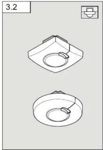
natural_image
Technical line drawing of two mechanical components with circular features, no text or symbols present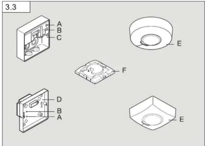
6
7
8
9
DE
- Please read carefully and keep in a safe place.
- Under copyright. Reproduction either in whole or in part only with our consent.
- Subject to change in the interest of technical progress.
Symbols
Hazard warning!
Reference to other information in the document.
2. General safety precautions

Disconnect the power supply before attempting any work on the sensor.
- This product must only be installed by a qualified electrician in accordance with national wiring regulations as defined in VDE 08 29 (DIN EN 5000 90).
- Installed improperly, low-voltage products can cause extremely serious personal injury or damage to property.
- This product must never be connected to a 230 V AC power supply as it is intended for connection to an extra-low voltage power supply.
- Only use genuine replacement parts.
• Repairs may only be made by specialist workshops.
3. HF 3360 KNX
Proper use
– Sensor suitable for indoor wall and ceiling-mounting
The Sensor is suitable for switching on a light automatically. The unit is not suitable for burglar alarm systems as it is not tamperproof in the manner prescribed for such systems.
The HF 3360 KNX is an active motion detector. It responds to the slightest movement regardless of temperature. The integrated HF sensor emits high-frequency electromagnetic waves (5.8 GHz) and receives their echo. In response to the slightest movement in the detection zone, the change in echo is perceived by the sensor. A microprocessor then issues the switch command "switch light ON". Detection is possible through doors, panes of glass or thin walls.
Optionally, all function settings can be made via the RC6, RC7 remote controls as well as the Smart Remote. (→ 7. Accessories)
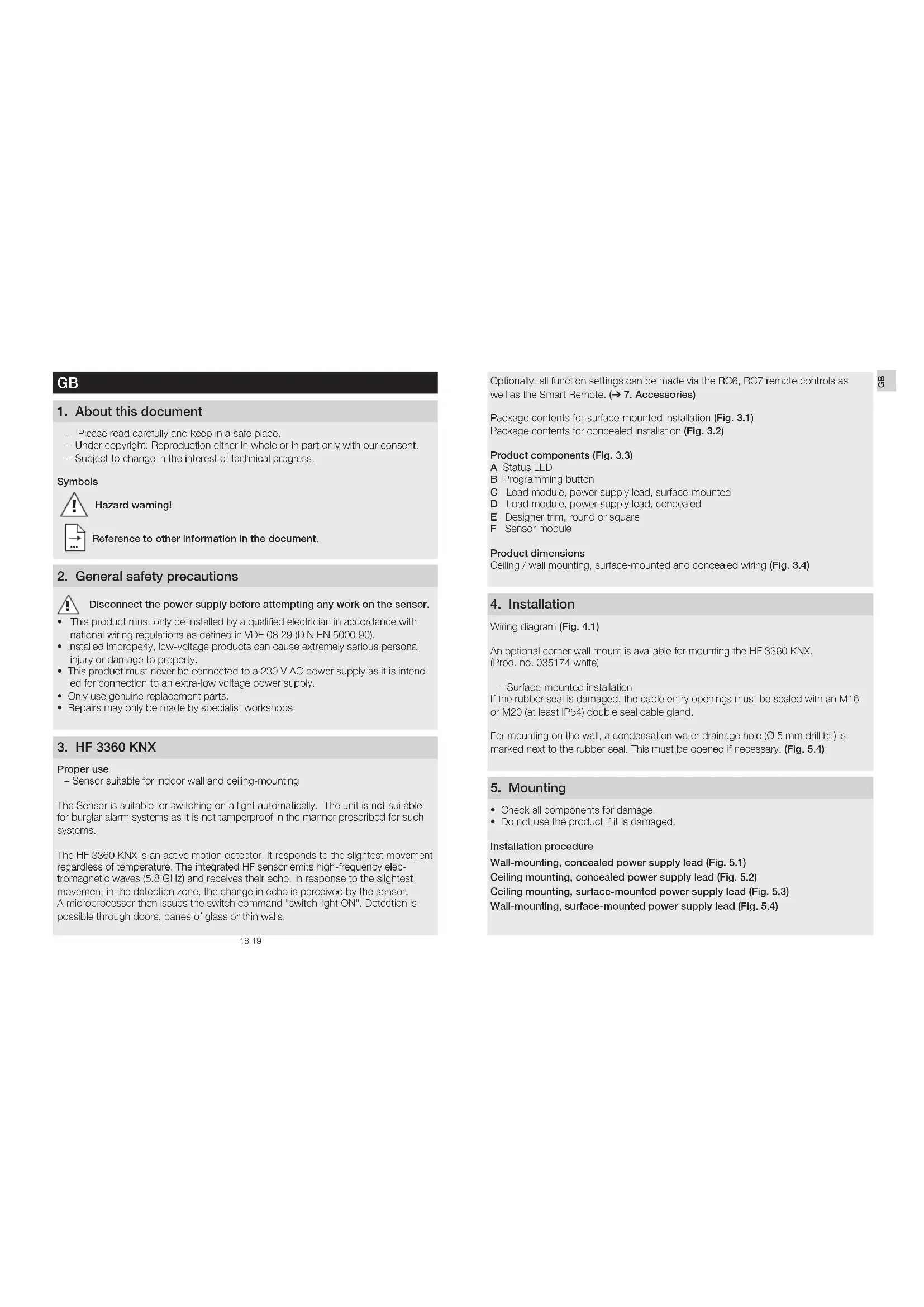
Package contents for surface-mounted installation (Fig. 3.1) Package contents for concealed installation (Fig. 3.2)
Product components (Fig. 3.3)
A Status LED
B Programming button
C Load module, power supply lead, surface-mounted
D Load module, power supply lead, concealed
E Designer trim, round or square
F Sensor module
Product dimensions
Ceiling / wall mounting, surface-mounted and concealed wiring (Fig. 3.4)
4. Installation
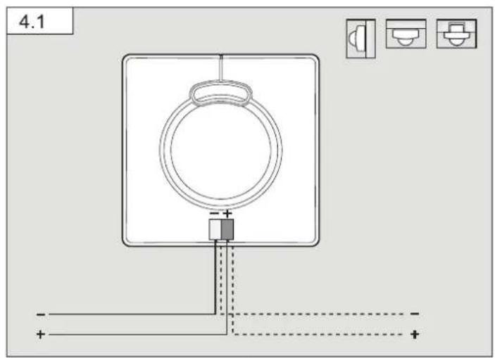
Wiring diagram (Fig. 4.1)
An optional corner wall mount is available for mounting the HF 3360 KNX. (Prod. no. 035174 white)
- Surface-mounted installation
If the rubber seal is damaged, the cable entry openings must be sealed with an M16 or M20 (at least IP54) double seal cable gland.
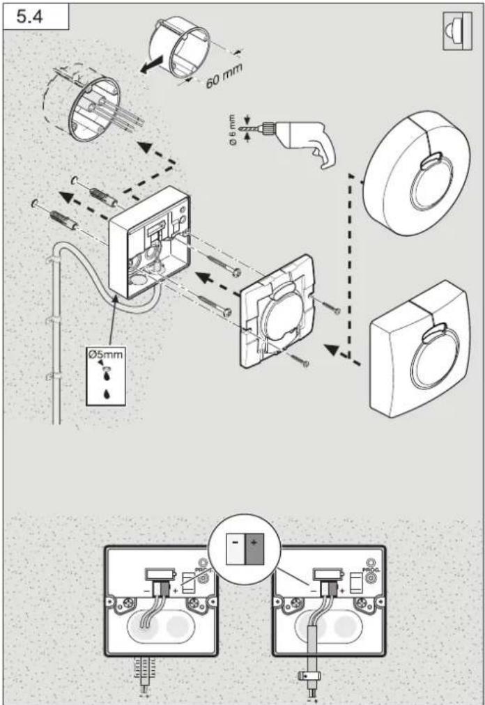
For mounting on the wall, a condensation water drainage hole ( 5 mm drill bit) is marked next to the rubber seal. This must be opened if necessary. (Fig. 5.4)
5. Mounting
- Check all components for damage.
- Do not use the product if it is damaged.
Installation procedure
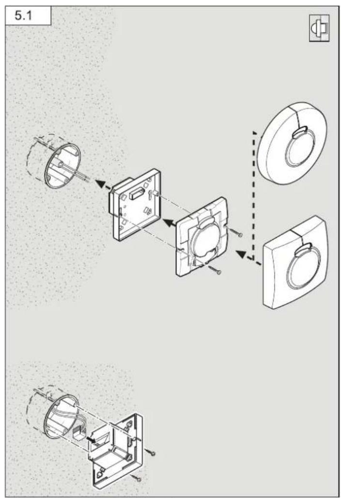
Wall-mounting, concealed power supply lead (Fig. 5.1)
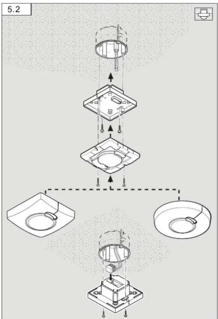
Ceiling mounting, concealed power supply lead (Fig. 5.2)
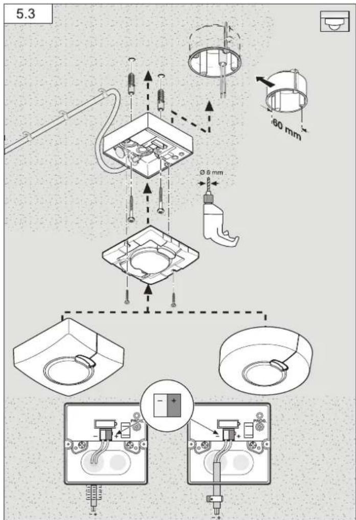
Ceiling mounting, surface-mounted power supply lead (Fig. 5.3)
Wall-mounting, surface-mounted power supply lead (Fig. 5.4)
- Detach designer trim from sensor module.
- Disconnect sensor module from the load module.
Concealed mounting (Fig. 5.1 / 5.2)
• Make plug connection.
- Press the programming button (B)
- Insert fastening screws and mount load module.
• Make settings. (→ 6. Functions and settings)
Surface mounting (Fig. 5.3 / 5.4)
- Insert fastening screws and mount load module.
• Make plug connection. - Press the programming button (B).
• Make settings. (Functions and settings)
• Fit sensor and load module together and screw into place. - Fit designer trim.
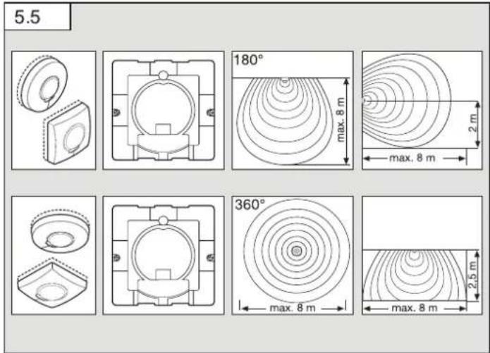
Reach diagram (Fig. 5.5)
6. Functions/settings
You will find an application description at knx.steinel.de
Functions to be used are selected from the "General Settings" parameter window using the Engineering Tool Software (ETS) from version ETS4.0.
- Issue physical address and generate application program in the ETS.
- Load the physical address and application program into the motion detector. When you are prompted, press programming button (B)
- The red LED goes out once programming has been successfully completed.
Functions, RC6
- Servicemode
- Reach, sensor sensitivity HF
– Light level, brightness setting, teach-in - Lighting control stay-ON time
– HVAC switch-ON delay, room surveillance, HVAC stay-ON time - Basic lighting stay-ON time, brightness setting, teach-in
- Presence- and lighting test mode
Functions, RC7
- Dimming function
- Light ON/OFF 4 h
– Saving, activating scene - Reset
Smart Remote
- Replaces remote controls RC6 and RC7
- Control via smartphone or tablet
- Load appropriate app and connect via Bluetooth
Additional functions, Smart Remote
- Programme mode
LED function
- Programming mode: LED ON
- Normal mode: LED stays OFF
- Test mode: LED lights up on detecting movement
- Remote control: LED flashes 10 times per second
Detailed descriptions are provided in the operating instructions for the particular remote control.
7. Accessories (optional)
- User remote control RC6 EAN 4007841 593018
- Service remote control RC7 EAN 4007841 592912
- Smart Remote EAN 4007841 009151
8. Maintenance / care
No maintenance possible.
The detector lens may be cleaned with a damp cloth if it becomes dirty (do not use cleaning agents).
9. Disposal
Electrical and electronic equipment, accessories and packaging must be recycled in an environmentally compatible manner.

Do not dispose of electrical and electronic equipment as domestic waste.
EU countries only:
Under the current European Directive on Waste Electrical and Electronic Equipment and its implementation in national law, electrical and electronic equipment no longer suitable for use must be collected separately and recycled in an environmentally compatible manner.
10. Declaration of Conformity
Hereby, STEINEL Vertrieb GmbH declares that the radio equipment type HF 3360 KNX is in compliance with Directive 2014/53/EU. The full text of the EU declaration of conformity is available at the following internet address: www.steinel.de
11. Manufacturer's Warranty
As purchaser, you are entitled to your statutory rights against the vendor. If these rights exist in your country, they are neither curtailed nor restricted by our Warranty Declaration. We guarantee that your STEINEL Professional sensor product will remain in perfect condition and proper working order for a period of 5 years. We guarantee that this product is free from material-, manufacturing- and design flaws. In addition, we guarantee that all electronic components and cables function in the proper manner and that all materials used and their surfaces are without defects.
Making Claims
If you wish to make a claim, please send your product complete and carriage paid with the original receipt of purchase, which must show the date of purchase and product designation, either to your retailer or contact us at STEINEL (UK) Limited, 25 Manasty Road, Axis Park, Orton Southgate, Peterborough, PE2 6UP, for a returns number. For this reason, we recommend that you keep your receipt of purchase in a safe place until the warranty period expires. STEINEL shall assume no liability for the costs or risks involved in returning a product.
For information on making claims under the terms of the warranty, please go to www.steinel-professional.de/garantie
If you have a warranty claim or would like to ask any question regarding your product, you are welcome to call us at any time on our Service Hotline 01733 366700.

- Troubleshooting
Malfunction Cause Remedy
| No power at the sensor | ■ Break in wiring | ■ Check KNX power supply |
| Sensor will not switch ON | ■ Bulb faulty■ Twilight setting set to night-time mode during daytime operation | ■ Change bulb■ Adjust setting |
| Sensor will not switch OFF | ■ Continuous movement in the detection zone | ■ Check zone |
| Sensor keeps switching ON/OFF | ■ Curtains, plant etc. moving in the sensor's detection zone causing the sensor to respond | ■ Check zone |
| Sensor responds when it should not | ■ Sensor near Wi-Fi or other wireless communication sources | ■ install at least 2 m away from the wireless communication source |
- Technical specifications
| Dimensions (H × W × D) | Surface-mounted installation, round ∅ | 126 × 52 mm |
| Surface-mounted installation, square | 95 × 95 × 52 mm | |
| Concealed installation, round ∅ | 124 × 64 mm | |
| Concealed installation, square | 94 × 94 × 64 mm | |
| Application inside buildings | ||
| Power supply KNX bus voltage, 21 V - 30 V | ——(SELV) | |
| Sensor system 5.8 GHz high frequency | ||
| Mounting height 2-2.8 m | ||
| Transmitter power approx. 1 mW | ||
| Settings via ETS software, remote control or BUS | ||
| Angle of coverage | 360° with 180° angle of aperture | |
| Basic brightness | 1 - 255 min | |
| Twilight setting | 2 - 1000 lux, teach | |
| Light output | Switching / dimming / basic brightness | |
| Light 1 - Light 2 | ||
| Lighting stay-ON time | 1 - 255 min | |
| HVAC stay-ON time | 1 - 255 min | |
| HVAC switch-ON delay | Room surveillance, 1 - 255 min | |
| Further outputs | In-operation telegram | |
| IP rating Surface-mounted: IP54 | Concealed: IP20 | |
| Temperature range | -20°C to +50°C | |
FR
Maintenance impossible.
Skjult montering (ill. 5.1/5.2)
Äpen montering (ill. 5.3/5.4)
们:Rm.25A Huadu Mansion, No.828-838 Zhangyang Road, 200122 Shanghai,