HM216SPX - Saw SCHEPPACH - Free user manual and instructions
Find the device manual for free HM216SPX SCHEPPACH in PDF.
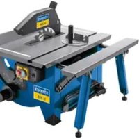
| Product type | Radial miter saw |
| Brand | Scheppach |
| Model | HM216SPX |
| Rated voltage | 220-240 V~ 50 Hz |
| Rated power S1 | 1700 W |
| Power S6 25% | 2000 W |
| No-load speed | 800 min⁻¹ |
| Saw blade | ø210 x ø30 x 2.6 mm, 24 teeth |
| Cutting width at 90° | 340 x 65 mm |
| Cutting width at 45° | 240 x 65 mm |
| Tilt range | -45° / 0° / +45° |
| Miter range | 0° to 45° left |
| Protection class | II (double insulation) |
| Weight | approx. 12.15 kg |
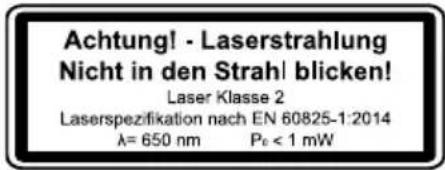
| Laser | Class 2, 650 nm, <1 mW |
| Sound pressure level | 96.5 dB(A) (uncertainty 3 dB) |
| Sound power level | 109.5 dB(A) (uncertainty 3 dB) |
| Mobile protective guard | Yes |
| Clamping device | Yes, with clamp |
| Chip collection bag | Yes |
| Radial guide | Yes, with lock |
| Longitudinal stop | Yes, folding |
| Extendable side supports | Yes, 2 pieces |
Frequently Asked Questions - HM216SPX SCHEPPACH
User questions about HM216SPX SCHEPPACH
0 question about this device. Answer the ones you know or ask your own.
Ask a new question about this device
Download the instructions for your Saw in PDF format for free! Find your manual HM216SPX - SCHEPPACH and take your electronic device back in hand. On this page are published all the documents necessary for the use of your device. HM216SPX by SCHEPPACH.
USER MANUAL HM216SPX SCHEPPACH
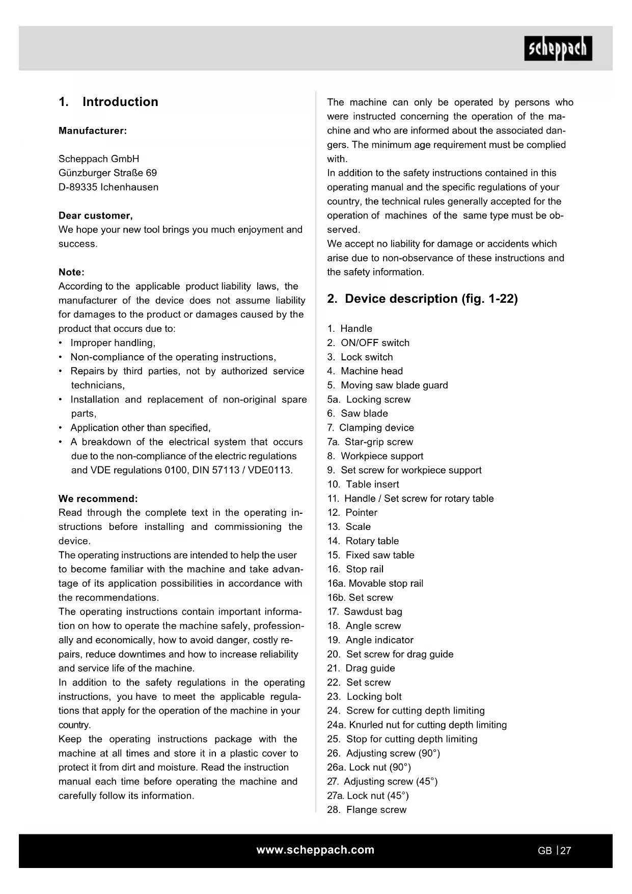
natural_image
Product photo of a cutting mill with a saw blade and two separate circular saw sets (no visible text or symbols)
Made in P.R.C.
| DE | Kapp-, Zug- und GehrungssägeOriginalbetriebsanleitung | 6 |
| GB | Sliding cross-cut mitre sawTranslation of original instruction manual | 25 |
| FR | Scie à onglet radialeTraduction des instructions d'origine | 40 |
| IT | Sega troncatrice, a trazione e per tagli obliquiLa traduzione dal manuale di istruzioni originale | 57 |
| NL | Afkort-, trek- en verstekzaagVertaling van de originele gebruikshandleiding | 74 |
| ES | Sierra tronzadora, de tracción y de cortar ingletesTraducción del manual de instrucciones original | 91 |
| PT | Serra de esquadria, de traçar e angularTradução do manual de operação original | 109 |
| CZ | Kapovací, dvouruční pila a pila na pokosPřeklad originálního návodu k obsluze | 126 |
| SK | Skracovacia, dvojručná a pokosová pílaPreklad originálneho návodu na obsluhu | 141 |
| HU | Fejező, vonó- és gérvágó fűrészEredeti használati utasítás fordítása | 157 |
| PL | Pilarka przesuwna do cięcia kątowego i ukośnegoTłumaczenie oryginalnej instrukcji obsługi | 173 |
| HR | Presječna, vlačna i kutna pilaPrijevod originalnog priručnika za uporabu | 190 |
| SI | Čelilna, vlečna in zajeralna žagaPrevod originalnih navodil za uporabo | 205 |
| EE | Otsamis-, tömbe ja eerungisaagOriginaalkäitusjuhendi tõlge | 221 |
| LT | Dvirankis skersinio ir įstrižinio pjaustymo pjūklasOriginalios naudojimo instrukcijos vertimas | 236 |
| LV | Sagarumošanas zāgis, škērszāgis un leŋkzāgisOriginālās lietošanas instrukcijas tulkojums | 251 |
| SE | Kap-, drag- och geringssågÖversättning av original-bruksanvisning | 267 |
| FI | Katkaisu-, liuku- ja viistesahaKäännös alkuperäisestä käyttöohjeesta | 282 |
| DK | Kap-, træk- og geringssavOversættelse fra den oprindelige betjeningsvejledning | 298 |
| NO | Kapp-, trekk- og gjæringssagOversettelse av den originale brukerveiledningen | 313 |
| BG | Циркулярен трион с изтегляне и герунгПревод на оригиналното ръководство за експлоатация | 328 |
| GR | Δισκοπρίονο κάθετης κοπής, συρόμενης κοπής - фалτσοπρίονοΜετάφραση του πρωτοτύπου των οδηγιών χρήσης | 346 |
| RO | Ferăstrău pentru retezare, ferăstrău-joagăr și pentru îmbinări de colțTraducere din manualul de exploatare original | 364 |
| RS | Preklopna, potezna i ugaona testeraPrevod originalnog uputstva za upotrebu | 381 |
| TR | Gönye, iki kollu ve gönyeburun testeresiOriginal kullanım talimatı çevirisi | 397 |

Günzburger Straße 69
D-89335 Ichenhausen
Verehrter Kunde,
Homepage: https://www.scheppach.com/de/service
Explanation of the symbols on the device
Symbols are used in this manual to draw your attention to potential hazards. The safety symbols and the accompanying explanations must be fully understood. The warnings themselves will not rectify a hazard and cannot replace proper accident prevention measures.
 | Before commissioning, read and observe the operating instructions and safety instructions! |
 | Wear ear-muffs! |
 | Wear a breathing mask! |
 | Wear safety goggles! |
 | Important! Risk of injury. Never reach into the running saw blade! |
  | Important! Laser radiation |
 | Protection Class II (double shielded) |
| △ Attention! | We have marked points in this operating manual that impact your safety with this symbol. |
 | The product complies with the applicable European directives. |
 | The product complies with the applicable Serbian directives. |
Table of contents: Page:
- Introduction....27
- Device description (fig. 1-22)....27
- Scope of delivery 28
- Intended use 28
- Safety information....28
- Technical data.... 32
- Before starting the equipment 33
- Attachment....33
- Operation....34
- Maintenance 36
- Transport....37
- Storage 38
- Electrical connection 38
- Disposal and recycling....38
- Troubleshooting 39
- Declaration of conformity 414
1. Introduction
Manufacturer:
Scheppach GmbH
Günzburger Straße 69
D-89335 Ichenhausen
Dear customer,
We hope your new tool brings you much enjoyment and success.
Note:
According to the applicable product liability laws, the manufacturer of the device does not assume liability for damages to the product or damages caused by the product that occurs due to:
- Improper handling,
• Non-compliance of the operating instructions, - Repairs by third parties, not by authorized service technicians,
• Installation and replacement of non-original spare parts,
• Application other than specified, - A breakdown of the electrical system that occurs due to the non-compliance of the electric regulations and VDE regulations 0100, DIN 57113 / VDE0113.
We recommend:
Read through the complete text in the operating instructions before installing and commissioning the device.
The operating instructions are intended to help the user to become familiar with the machine and take advantage of its application possibilities in accordance with the recommendations.
The operating instructions contain important information on how to operate the machine safely, professionally and economically, how to avoid danger, costly repairs, reduce downtimes and how to increase reliability and service life of the machine.
In addition to the safety regulations in the operating instructions, you have to meet the applicable regulations that apply for the operation of the machine in your country.
Keep the operating instructions package with the machine at all times and store it in a plastic cover to protect it from dirt and moisture. Read the instruction manual each time before operating the machine and carefully follow its information.
The machine can only be operated by persons who were instructed concerning the operation of the machine and who are informed about the associated dangers. The minimum age requirement must be complied with.
In addition to the safety instructions contained in this operating manual and the specific regulations of your country, the technical rules generally accepted for the operation of machines of the same type must be observed.
We accept no liability for damage or accidents which arise due to non-observance of these instructions and the safety information.
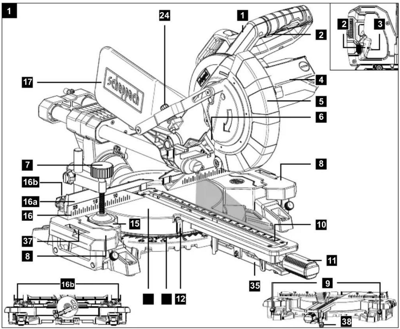
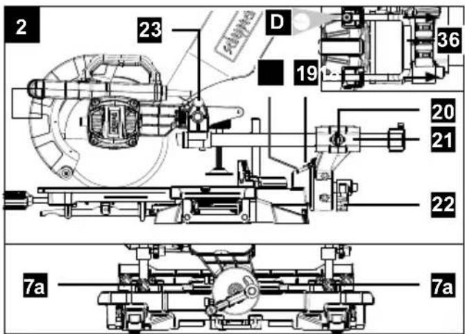
2. Device description (fig. 1-22)
- Handle
- ON/OFF switch
- Lock switch
- Machine head
- Moving saw blade guard
5a. Locking screw - Saw blade
- Clamping device
7a. Star-grip screw - Workpiece support
- Set screw for workpiece support
- Table insert
- Handle / Set screw for rotary table
- Pointer
- Scale
- Rotary table
- Fixed saw table
- Stop rail
16a. Movable stop rail
16b. Set screw - Sawdust bag
- Angle screw
- Angle indicator
- Set screw for drag guide
- Drag guide
- Set screw
- Locking bolt
- Screw for cutting depth limiting
24a. Knurled nut for cutting depth limiting - Stop for cutting depth limiting
- Adjusting screw (90°)
26a. Lock nut (90°) - Adjusting screw (45°)
27a. Lock nut (45°) -
Flange screw
-
Outer flange
-
Saw shaft lock
-
Inner flange
-
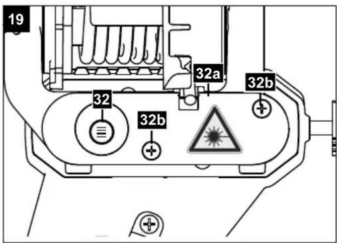
Laser
32a. Laser housing cover
32b. Phillips screw
-
ON/OFF switch laser
-
Guide bracket
-
Latched position lever
-
Tilt protection
-
Length stop
-
Adjustment screw
A.) 90° stop angle (not supplied)
B.) 45^ stop angle (not supplied)
C.) Allen key, 6 mm
D.) Allen key, 3 mm
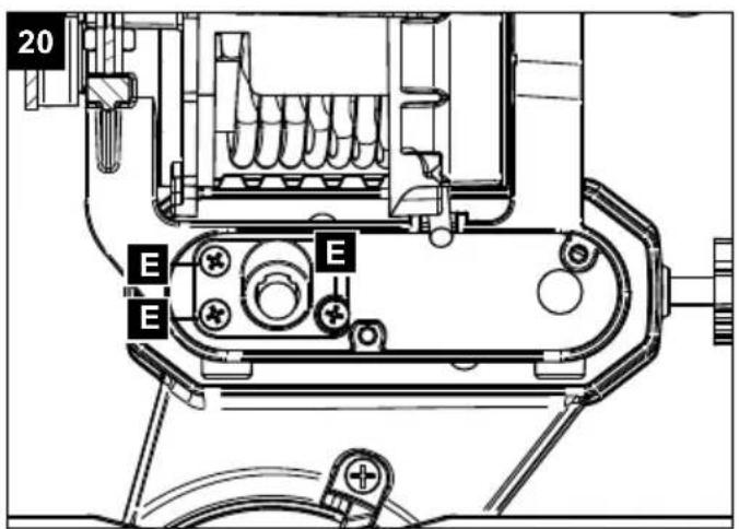
E.) Phillips head screw (Laser)
3. Scope of delivery
• Sliding cross-cut mitre saw
• 1 x Clamping device (7)
- 2 x Workpiece support (8) (preassembled)
- Sawdust bag (17)
- Allen key 6 mm (C)
- Allen key 3 mm (D)
- Operating manual
4. Intended use
The crosscut, drag and mitre saw is designed to cross-cut wood and plastic respective of the machine's size. The saw is not designed for cutting firewood.
Warning!
Do not use the saw to cut materials other than those specified described in manual.
Warning!
The supplied saw blade is only intended for the sawing of wood! Do not use this blade for the sawing of firewood!
The equipment is to be used only for its prescribed purpose. Any other use is deemed to be a case of misuse. The user / operator and not the manufacturer will be liable for any damage or injuries of any kind caused as a result of this.
The equipment is to be operated only with suitable saw blades. It is prohibited to use any type of cutting-off wheel.
To use the equipment properly you must also observe the safety information, the assembly instructions and the operating instructions to be found in this manual.
All persons who use and service the equipment have to be acquainted with this manual and must be informed about the equipment's potential hazards.
It is also imperative to observe the accident prevention regulations in force in your area.
The same applies for the general rules of health and safety at work.
The manufacturer will not be liable for any changes made to the equipment nor for any damage resulting from such changes.
Even when the equipment is used as prescribed it is still impossible to eliminate certain residual risk factors. The following hazards may arise in connection with the machine's construction and design:
- Contact with the saw blade in the uncovered saw zone.
- Reaching into the running saw blade (cut injuries).
- Kick-back of workpieces and parts of workpieces.
- Saw blade fracturing.
- Catapulting of faulty carbide tips from the saw blade.
- Damage to hearing if ear-muffs are not used as necessary.
- Harmful emissions of wood dust when used in closed rooms.
Please note that our equipment has not been designed for use in commercial, trade or industrial applications. Our warranty will be voided if the equipment is used in commercial, trade or industrial businesses or for equivalent purposes.
5. Safety information
General power tool safety warnings
⚠ WARNING! Read all safety warnings, instructions, illustrations and specifications provided with this power tool. Failure to follow all instructions listed below may result in electric shock, fire and/or serious injury.
Save all warnings and instructions for future reference.
The term "power tool" in the warnings refers to your mains-operated (corded) power tool or battery-operated (cordless) power tool.
- Work area safety
a. Keep work area clean and well lit. Cluttered or dark areas invite accidents.
b. Do not operate power tools in explosive atmospheres, such as in the presence of flammable liquids, gases or dust. Power tools create sparks which may ignite the dust or fumes.
c. Keep children and bystanders away while operating a power tool. Distractions can cause you to lose control.
- Electrical safety
a. Power tool plugs must match the outlet. Never modify the plug in any way. Do not use any adapter plugs with earthed (grounded) power tools. Unmodified plugs and matching outlets will reduce risk of electric shock.
b. Avoid body contact with earthed or grounded surfaces, such as pipes, radiators, ranges and refrigerators. There is an increased risk of electric shock if your body is earthed or grounded.
c. Do not expose power tools to rain or wet conditions. Water entering a power tool will increase the risk of electric shock.
d. Do not abuse the cord. Never use the cord for carrying, pulling or unplugging the power tool. Keep cord away from heat, oil, sharp edges or moving parts. Damaged or entangled cords increase the risk of electric shock.
e. When operating a power tool outdoors, use an extension cord suitable for outdoor use. Use of a cord suitable for outdoor use reduces the risk of electric shock.
f. If operating a power tool in a damp location is unavoidable, use a residual current device (RCD) protected supply. Use of an RCD reduces the risk of electric shock.
- Personal safety
a. Stay alert, watch what you are doing and use common sense when operating a power tool. Do not use a power tool while you are tired or under the influence of drugs, alcohol or medication. A moment of inattention while operating power tools may result in serious personal injury.
b. Use personal protective equipment. Always wear eye protection.
Protective equipment such as a dust mask, non-skid safety shoes, hard hat or hearing protection used for appropriate conditions will reduce personal injuries.
c. Prevent unintentional starting. Ensure the switch is in the off-position before connecting to power source and/or battery pack, picking up or carrying the tool. Carrying power tools with your finger on the switch or energising power tools that have the switch on invites accidents.
d. Remove any adjusting key or wrench before turning the power tool on. A wrench or a key left attached to a rotating part of the power tool may result in personal injury.
e. Do not overreach. Keep proper footing and balance at all times. This enables better control of the power tool in unexpected situations.
f. Dress properly. Do not wear loose clothing or jewellery. Keep your hair and clothing away from moving parts. Loose clothes, jewellery or long hair can be caught in moving parts.
g. If devices are provided for the connection of dust extraction and collection facilities, ensure these are connected and properly used. Use of dust collection can reduce dust-related hazards.
h. Do not let familiarity gained from frequent use of tools allow you to become complacent and ignore tool safety principles. A careless action can cause severe injury within a fraction of a second.
- Power tool use and care
a. Do not force the power tool. Use the correct power tool for your application. The correct power tool will do the job better and safer at the rate for which it was designed.
b. Do not use the power tool if the switch does not turn it on and off. Any power tool that cannot be controlled with the switch is dangerous and must be repaired.
c. Disconnect the plug from the power source and/or remove the battery pack, if detachable, from the power tool before making any adjustments, changing accessories, or storing power tools. Such preventive safety measures reduce the risk of starting the power tool accidentally.
d. Store idle power tools out of the reach of children and do not allow persons unfamiliar with the power tool or these instructions to operate the power tool. Power tools are dangerous in the hands of untrained users.
e. Maintain power tools and accessories. Check for misalignment or binding of moving parts, breakage of parts and any other condition that may affect the power tool's operation. If damaged, have the power tool repaired before use. Many accidents are caused by poorly maintained power tools.
f. Keep cutting tools sharp and clean. Properly maintained cutting tools with sharp cutting edges are less likely to bind and are easier to control.
g. Use the power tool, accessories and tool bits etc. in accordance with these instructions, taking into account the working conditions and the work to be performed. Use of the power tool for operations different from those intended could result in a hazardous situation.
h. Keep handles and grasping surfaces dry, clean and free from oil and grease. Slippery handles and grasping surfaces do not allow for safe handling and control of the tool in unexpected situations.
5. Service
a. Have your power tool serviced by a qualified repair person using only identical replacement parts. This will ensure that the safety of the power tool is maintained.
Safety instructions for mitre saws
a) Mitre saws are intended to cut wood or wood-like products, they cannot be used with abrasive cut-off wheels for cutting ferrous material such as bars, rods, studs, etc. Abrasive dust causes moving parts such as the lower guard to jam. Sparks from abrasive cutting will burn the lower guard, the kerf insert and other plastic parts.
b) Use clamps to support the workpiece whenever possible. If supporting the workpiece by hand, you must always keep your hand at least 100 mm from either side of the saw blade. Do not use this saw to cut pieces that are too small to be securely clamped or held by hand. If your hand is placed too close to the saw blade, there is an increased risk of injury from blade contact.
c) The workpiece must be stationary and clamped or held against both the fence and the table. Do not feed the workpiece into the blade or cut "freehand" in any way. Unrestrained or moving workpieces could be thrown at high speeds, causing injury.
d) Push the saw through the workpiece. Do not pull the saw through the workpiece. To make a cut, raise the saw head and pull it out over the workpiece without cutting, start the motor, press the saw head down and push the saw through the workpiece. Cutting on the pull stroke is likely to cause the saw blade to climb on top of the workpiece and violently throw the blade assembly towards the operator.
e) Never cross your hand over the intended line of cutting either in front or behind the saw blade. Supporting the workpiece "cross handed" i.e. holding the workpiece to the right of the saw blade with your left hand or vice versa is very dangerous.
f) Do not reach behind the fence with either hand closer than 100 mm from either side of the saw blade, to remove wood scraps, or for any other reason while the blade is spinning. The proximity of the spinning saw blade to your hand may not be obvious and you may be seriously injured.
g) Inspect your workpiece before cutting. If the workpiece is bowed or warped, clamp it with the outside bowed face toward the fence. Always make certain that there is no gap between the workpiece, fence and table along the line of the cut. Bent or warped workpieces can twist or shift and may cause binding on the spinning saw blade while cutting. There should be no nails or foreign objects in the workpiece.
h) Do not use the saw until the table is clear of all tools, wood scraps, etc., except for the workpiece. Small debris or loose pieces of wood or other objects that contact the revolving blade can be thrown with high speed.
i) Cut only one workpiece at a time. Stacked multiple workpieces cannot be adequately clamped or braced and may bind on the blade or shift during cutting.
j) Ensure the mitre saw is mounted or placed on a level, firm work surface before use. A level and firm work surface reduces the risk of the mitre saw becoming unstable.
k) Plan your work. Every time you change the bevel or mitre angle setting, make sure the adjustable fence is set correctly to support the workpiece and will not interfere with the blade or the guarding system. Without turning the tool "ON" and with no workpiece on the table, move the saw blade through a complete simulated cut to assure there will be no interference or danger of cutting the fence.
I) Provide adequate support such as table extensions, saw horses, etc. for a workpiece that is wider or longer than the table top. Workpieces longer or wider than the mitre saw table can tip if not securely supported. If the cut-off piece or workpiece tips, it can lift the lower guard or be thrown by the spinning blade.
m) Do not use another person as a substitute for a table extension or as additional support. Unstable support for the workpiece can cause the blade to bind or the workpiece to shift during the cutting operation pulling you and the helper into the spinning blade.
n) The cut-off piece must not be jammed or pressed by any means against the spinning saw blade. If confined, i.e. using length stops, the cut-off piece could get wedged against the blade and thrown violently.
o) Always use a clamp or a fixture designed to properly support round material such as rods or tubing. Rods have a tendency to roll while being cut, causing the blade to "bite" and pull the work with your hand into the blade.
p) Let the blade reach full speed before contacting the workpiece. This will reduce the risk of the workpiece being thrown.
q) If the workpiece or blade becomes jammed, turn the mitre saw off. Wait for all moving parts to stop and disconnect the plug from the power source and/or remove the battery pack. Then work to free the jammed material. Continued sawing with a jammed workpiece could cause loss of control or damage to the mitre saw.
r) After finishing the cut, release the switch, hold the saw head down and wait for the blade to stop before removing the cut-off piece. Reaching with your hand near the coasting blade is dangerous.
s) Hold the handle firmly when making an incomplete cut or when releasing the switch before the saw head is completely in the down position. The braking action of the saw may cause the saw head to be suddenly pulled downward, causing a risk of injury.
Safety Instructions for the handling of saw blades
- Do not use damaged or deformed saw blades.
- Do not use any insertion tools with cracks. Sort out cracked insertion tools. Repairs are not permitted.
- Do not use saw blades made of high speed steel.
-
Check the condition of the saw blades before using the crosscut, drag and mitre saw.
-
Make sure that a suitable saw blade for the material to be cut is selected.
- Only use saw blades recommended by the manufacturer. Saw blades designed to cut wood and similar materials must comply with EN 847-1.
- Do not use saw blades made of high-speed alloy steel (HSS steel).
- Only use saw blades for which the maximum permissible speed is not lower than the maximum spindle speed of the crosscut, drag and mitre saw and which are suitable for the material to be cut.
- Observe the saw blade direction of rotation.
- Only insertion the saw blade if you have mastered their use.
- Observe the maximum speed. The maximum speed specified on the insertion tool may not be exceeded. If specified, observe the speed range.
- Clean grease, oil and water off of the clamping surfaces.
- Do not use any loose reducing rings or bushes for the reducing of holes on saw blades.
- Make sure that fixed reducer rings for securing the insertion tool have the same diameter and have at least 1/3 of the cutting diameter.
- Make sure that fixed reducer rings are parallel to each other.
- Handle insertion tool with caution. They are ideally stored in the originally package or special containers. Wear protective gloves in order to improve grip and to further reduce the risk of injury.
- Prior to the use of insertion tools, make sure that all protective devices are properly fastened.
- Prior to use, make sure that the insertion tool meets the technical requirements of this electric tool and is properly fastened.
- Only use the supplied saw blade for cutting wood, never for the processing of metals.
- Only use saw blade diameters in accordance with the markings on the saw.
- Use additional workpiece supports, if required for workpiece stability.
- Workpiece support extensions must always be secured and used during work.
- Replace table inserts when worn!
- Avoid overheating of the saw teeth.
- When sawing plastic, avoid melting of the plastic. Use the appropriate saw blades for this purpose. Replace damaged or worn saw blades immediately. When the saw blade overheats, stop the machine. Allow the saw blade to cool down before using the machine again.
Attention: Laser radiation Do not stare into the beam Class 2 laser
Protect yourself and you environment from accidents using suitable precautionary measures!
- Do not look directly into the laser beam with unprotected eyes.
- Never look into the path of the beam.
- Never point the laser beam towards reflecting surfaces and persons or animals. Even a laser beam with a low output can cause damage to the eyes.
- Caution - methods other than those specified here can result in dangerous radiation exposure.
- Never open the laser module. Unexpected exposure to the beam can occur.
- The laser may not be replaced with a different type of laser.
• Repairs of the laser may only be carried out by the laser manufacturer or an authorised representative.
Residual risks
The machine has been built according to the state of the art and the recognised technical safety requirements. However, individual residual risks can arise during operation.
• Health hazard due to electrical power, with the use of improper electrical connection cables.
• Furthermore, despite all precautions having been met, some non-obvious residual risks may still remain.
- Residual risks can be minimised if the „Safety information“ and the „Proper use“ are observed along with the whole of the operating instructions.
- Do not load the machine unnecessarily: excessive pressure when sawing will quickly damage the saw blade, which results in reduced output of the machine in the processing and in cut precision.
- When cutting plastic material, please always use clamps: the parts which should be cut must always be fixed between the clamps.
- Avoid accidental starting of the machine: the operating button may not be pressed when inserting the plug in an outlet.
- Use the tool that is recommended in this manual. In doing so, your machine provides optimal performance.
- Hands may never enter the processing zone when the machine is in operation.
- Release the handle button and switch off the machine prior to any operations.
Warning!
This electric tool generates an electromagnetic field during operation. This field can impair active or passive medical implants under certain conditions. In order to prevent the risk of serious or deadly injuries, we recommend that persons with medical implants consult with their physician and the manufacturer of the medical implant prior to operating the electric tool.
6. Technical data
AC motor....220 - 240 V\~ 50 Hz
Power S1....1700 Watt
Operating mode....S6 25%* 2000W
Idle speed n0 4800 min-1
Carbide saw blade....ø 210 x ø 30 x 2,6 mm
Number of teeth 24
Maximum tooth width of saw blade .... 3 mm
Swivel range -45° / 0° / +45°
Mitre cut 0° to 45° to the left
Saw width at 90° 340 x 65 mm
Saw width at 45° 240 x 65 mm
Saw width at 2 x 45°
(double mitre cut))....240 x 38 mm
Protection class II / ☐
Weight......ca. 12,15 kg
Laser class....2
Wavelength of laser 650 nm
Laser output .... < 1 mW
Subject to technical changes!
* S6, continuous operation periodic duty. Identical duty cycles with a period at load followed by a period at no load. Running time 10 minutes; duty cycle is 25% of the running time.
The work piece must have a minimum height of 3 mm and a minimum width of 10 mm.
Make sure that the workpiece is always secured with the clamping device.
Noise
Total noise values determined in accordance with EN 62841.
Sound pressure level L_pA .....96,5 dB
Uncertainty K_pA .....3 dB
Sound power level L_WA 109.5 dB
Uncertainty K_WA 3 dB
Wear hearing protection.
The effects of noise can cause a loss of hearing.
The above-mentioned noise emission values were measured in accordance with a standardised test procedure and can be used to compare one power tool with another.
The above-mentioned noise emission values can also be used for the preliminary assessment of exposure.
Warning:
- The noise emissions during the actual use of the power tool may differ from the above-mentioned values depending on the power tool being used, in particular on the type of workpiece being processed.
- Try to keep emissions as low as possible, for example by limiting your working time. In this regard, all the operational cycle phases must be taken into consideration (such as the times when the tool is switched off or running idle).
7. Before starting the equipment
- Open the packaging and remove the device carefully.
- Remove the packaging material as well as the packaging and transport bracing (if available).
- Check that the delivery is complete.
- Check the device and accessory parts for transport damage.
- If possible, store the packaging until the warranty period has expired.
ATTENTION
The device and packaging materials are not toys! Children must not be allowed to play with plastic bags, film and small parts! There is a risk of swallowing and suffocation!
- The equipment must be set up where it can stand securely. Secure the machine on a workbench, base frame or similar. Insert 4 screws (not included in the scope of delivery) into the holes on the fixed saw table (15). Tighten up the screws.
-
Loosen the tilt protection (36) pre-installed at the bottom of the saw, completely pull it out and secure it with an Allen key (D).
-
Adjust the adjusting screw (38) to the level of the tabletop to avoid wobbling of the machine.
- All covers and safety devices have to be properly fitted before the equipment is switched on.
- It must be possible for the blade to run freely.
- When working with wood that has been processed before, watch out for foreign bodies such as nails or screws, etc.
- Before you press the ON/OFF switch check that the saw blade is fitted correctly. Moving parts must run smoothly.
- Before you connect the equipment to the power supply make sure the data on the rating plate are identical to the mains data.
7.1 Checking the moving saw blade guard safety device (5)
The saw blade guard protects against accidental contact with the saw blade and from chips flying around.
Check function
To do so, fold the saw downwards:
- The saw blade guard must provide free access to the saw blade without touching other parts.
- When folding the saw upwards into the starting position, the saw blade guard must cover the saw blade automatically.
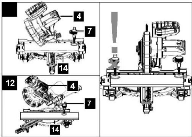
8. Attachment
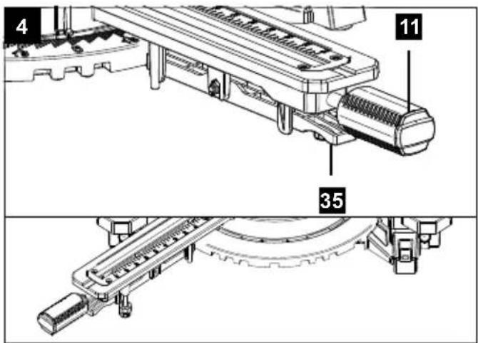
8.1 Attaching the crosscut, drag and mitre saw (fig. 1/2/4)
- In order to adjust the rotary table (14), loosen the handle (11) approximately 2 turns and pull up the latched position lever (35) with your index finger.
- Turn the rotary table (14) and pointer (12) to the desired angle measurement on the scale (13) and use the handle (11) to secure it.
- Press the machine head (4) down lightly. The saw is unlocked from the lower position by at the same time, pulling out and turning the locking pin (23) from the engine mount.
- Turn the locking bolt (23) 90 degrees to secure it in the unlocked position.
- Swing the machine head (4) up.
-
It is possible to secure the clamping devices (7) to the left or right on the fixed saw table (15). Insert the clamping devices (7) in the holes on the rear side of the stop rail (16) and secure it with the star grip screws (7a). For 0^ - 45^ mitre cuts, the clamping device (7) must only be mounted on the right side (see fig. 11-12).
-
It is possible to tilt the machine head (4) a max. 45^ to the left by loosening the set screw (22).
- Workpiece supports (8) must always be secured and used during work. Set the desired table size by loosening the set screw (9). Then tighten the set screw (9) again.
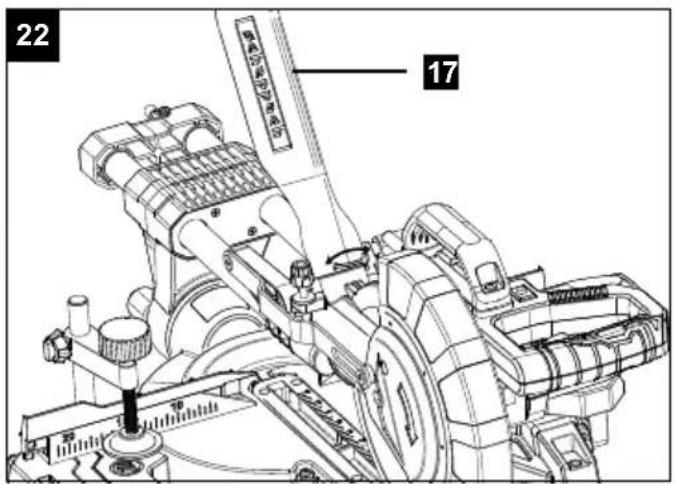
8.2 Sawdust bag (fig. 1/22)
The saw is equipped with a debris bag (17) for sawdust and chips.
Squeeze the wings of the metal ring on the dust bag (17) together and slide it over the discharge port near the engine.
The debris bag (17) can be emptied by means of a zipper at the bottom.
8.2.1 Connection to an external dust extractor
- Connect the vacuum hose with the dust extraction spout.
- The industrial vacuum cleaner must be suitable for the material being worked.
- When vacuuming dust that is especially detrimental to health or carcinogenic, use a special vacuum cleaner.
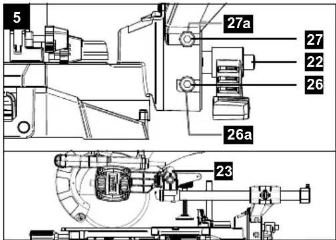
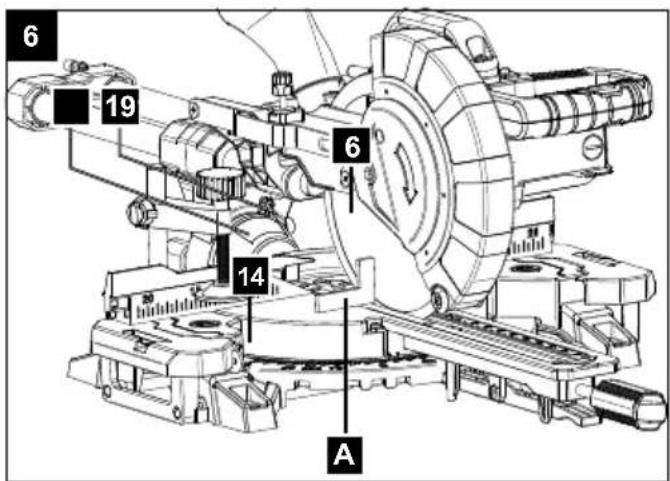
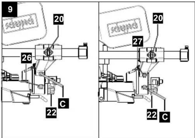
8.3 Precision adjustment of the stop for crosscut 90° (fig. 1/2/5/6)
Tools required:
- Allen key 6 mm
- Open-ended spanner SW13 (not included in the scope of delivery)
• No stop angle included.
- Lower the machine head (4) and secure it using the locking bolt (23).
- Loosen the set screw (22).
- Position the angle stop (A) between the saw blade (6) and the rotary table (14).
- Loosen the lock nut (26a).
- Adjust the adjusting screw (26) until the angle between the saw blade (6) and rotary table (14) is 90^ .
- Tighten the lock nut (26a) again.
- Subsequently check the position of the angle indicator. If necessary loosen the pointer (19) using a Phillips screwdriver, set to position 0^ on the angle scale (18) and re-tighten the retaining screw.
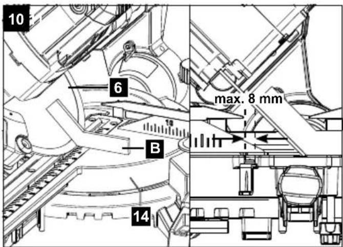
8.4 Precision adjustment of the stop for mitre cut 45^ (fig. 1/2/5/9/10)
Tools required:
- Allen key 6 mm
- Open-ended spanner SW13 (not included in the scope of delivery)
- No stop angle included.
- Lower the machine head (4) and secure it using the locking bolt (23).
• Fix the rotary table (14) in the 0° position.
- Attention!
For bevel cuts (inclined saw head), the moveable stop rail (16a) must be fixed in the outer position. (Left side).
- Open the set screw (16b) for the moveable stop rail (16a) and push the moveable stop rail (16a) outwards.
- The moveable stop rails (16a) must be locked so that the distance between the stop rails (16a) and the saw blade (6) is at least 8 mm.
- The moveable stop rail (28) must be fixed in the inner position. (Right side).
- Before making a cut, check that the stop rail (16a) and the saw blade (6) cannot collide.
- Loosen the set screw (22) and use the handle (1) to angle the machine head (4) 45^ to the left.
- 45^ - position angle stop (B) between the saw blade (6) and rotary table (14).
- Loosen the lock nut (27a) and adjust the screw (27) until the angle between the saw blade (6) and the rotary table (14) is precisely 45^ .
- Tighten the lock nut (27a) again.
- Subsequently check the position of the angle indicator. If necessary, loosen the pointer (19) using a Phillips screwdriver, set to position 45^ on the angle scale (18) and re-tighten the retaining screw.
9. Operation
ATTENTION!
Prior to use, ensure that the device has been correctly and fully assembled.
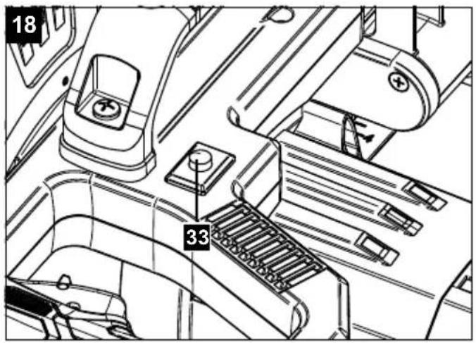
9.1 Using the laser (fig. 18)
To switch on:
Press the ON/OFF switch laser (33) 1x. A laser line is projected onto the material you wish to process, providing an exact guide for the cut.
To switch off:
Press again the ON/OFF switch laser (33).
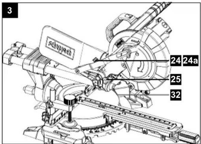
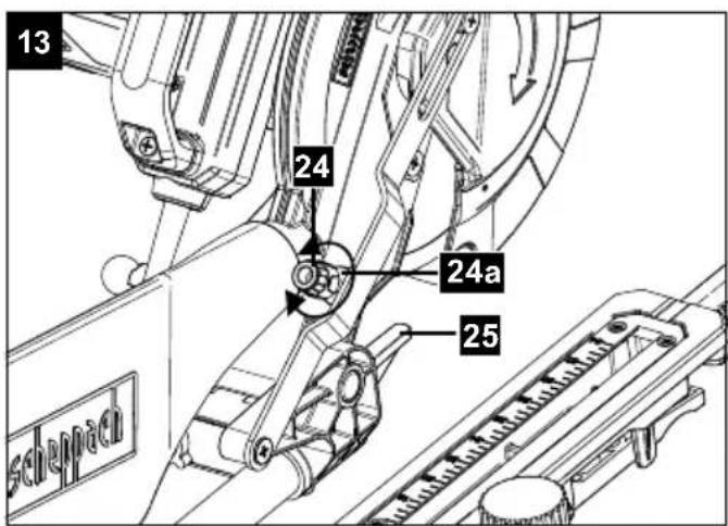
9.2 Limiting the cutting depth (cutting grooves) (fig. 3/13)
⚠ WARNING
Risk of kickback! When cutting grooves, it is particularly important that no lateral pressure is exerted on the saw blade. Otherwise, the saw head might suddenly kick back! Use a clamping device when cutting grooves. Avoid lateral pressure on the saw head.
- The cutting depth can be infinitely adjusted using the screw (24). To do this loosen the knurled nut (24a) on the screw (24). Turn the screw (24) in or out to set the required cutting depth. Then re-tighten the knurled nut (24a) on the screw (24).
- Check the setting by completing a test cut.
9.3 Serial cutting
For repeated cuts of the same length, the length stop (37) can be opened. You can use the length stop (37) on the right and on the left.
- Fold up the length stop (37).
- Loosen the set screw for workpiece support (9).
• Pull out the workpiece support (8). - Set the required dimension between saw blade and length stop (37).
• Re-tighten the set screw for workpiece support (9).
• Perform cutting as described in sections 9.4 to 9.7.
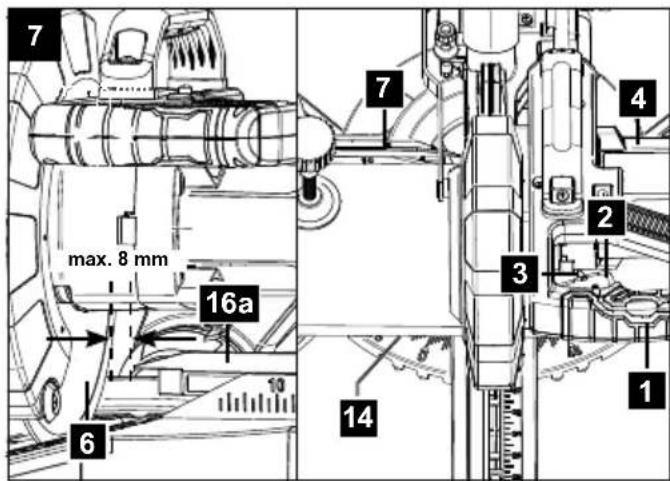
9.4 Crosscut 90° and turntable 0° (fig. 1/2/7)
In the case of cutting widths up to approx. 100 mm it is possible to fix the traction function of the saw with the set screw (20) in the rear position. In this position the machine can be operated in cross cutting mode. If the cutting width is over 100 mm then it is necessary to ensure that the set screw (20) is loose and the machine head (4) can move.
Attention!
For 90° crosscuts, the moveable stop rail (16a) must be fixed in the inner position.
- Open the set screw (16b) for the moveable stop rail (16a) and push the moveable stop rail (16a) inwards.
- The moveable stop rails (16a) must be locked so that the distance between the stop rails (16a) and the saw blade (6) is no more than 8 mm.
- Before making the cut, check that the stop rails (16a) and the saw blade (6) cannot collide.
• Re-tighten the set screw (16b). - Move the machine head (4) to its upper position.
- Use the handle (1) to push back the machine head (4) and fix it in this position if required (dependent on the cutting width).
- Place the piece of wood to be cut at the stop rail (16) and on the turntable (14).
- Lock the material with the clamping devices (7) on the fixed saw table (15) to prevent the material from moving during the cutting operation.
- Release the lock switch (3) and press the ON/OFF switch (2) to start the motor.
- With the drag guide (21) fixed in place: use the handle (1) to move the machine head (4) steadily and with light pressure downwards until the saw blade (6) has completely cut through the work piece.
- With the drag guide (21) not fixed in place: pull the machine head (4) all the way to the front. Lower the handle (1) to the very bottom by applying steady and light downward pressure. Now push the machine head (4) slowly and steadily to the very back until the saw blade (6) has completely cut through the work piece.
- When the cutting operation is completed, move the machine head back to its upper (home) position and release the ON/OFF button (2).
Attention! The machine executes an upward stroke automatically due to the return spring, i.e. do not release the handle (1) after completing the cut; instead allow the machine head to move upwards slowly whilst applying light counter pressure.
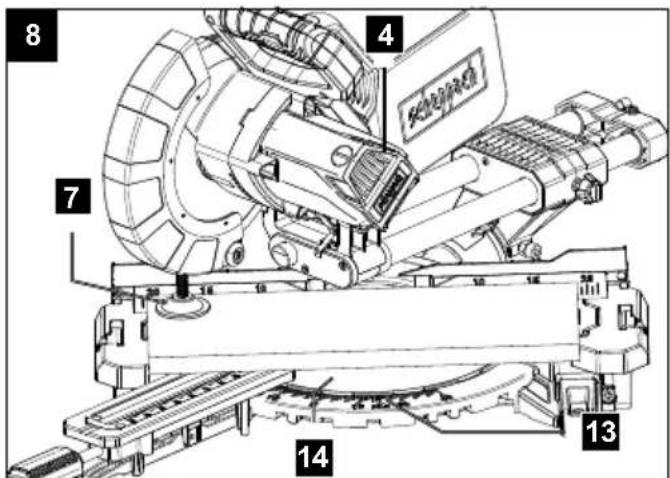
9.5 Crosscut 90° and turntable 0° - 45° (fig. 1/7/8)
The crosscut, drag and mitre saw can be used to make crosscuts of 0^ - 45^ to the left and 0^ - 45^ to the right in relation to the stop rail.
Important!
For 90° crosscuts, the moveable stop rail (16a) must be fixed in the inner position.
- Open the set screw (16b) for the moveable stop rail (16a) and push the moveable stop rail (16a) inwards.
- The moveable stop rails (16a) must be locked so that the distance between the stop rails (16a) and the saw blade (6) is at least 8 mm.
- Before making the cut, check that the stop rails (16a) and the saw blade (6) cannot collide.
- Secure the set screw (16b) again.
- Loosen the handle (11) if it is tightened. Pull the indexed position lever (35) upwards with the pointer finger. Adjust the rotary table (14) to the desired angle using the handle (11).
-
The pointer (12) on the rotary table must match the desired angle on the scale (13) on the fixed saw table (15).
-
Re-tighten the handle (11) to secure the rotary table (14).
• Cut as described under section 9.4.
9.6 Mitre cut 0°-45° and turntable 0° (fig. 1/2/11)
The crosscut, drag and mitre saw can be used to make mitre cuts of 0^ - 45^ in relation to the work face.
Attention!
For bevel cuts (inclined saw head), the moveable stop rail (16a) must be fixed in the outer position. (Left side).
- Open the set screw (16b) for the moveable stop rail (16a) and push the moveable stop rail (16a) outwards.
- The moveable stop rails (16a) must be locked so that the distance between the stop rails (16a) and the saw blade (6) is at least 8 mm.
- The moveable stop rail (28) must be fixed in the inner position. (Right side).
- Before making a cut, check that the stop rail (16a) and the saw blade (6) cannot collide.
- Secure the set screw (16b) again.
- Move the machine head (4) to the top position.
• Fix the rotary table (14) in the 0° position. - Loosen the set screw (22). Use the handle (1) to angle the machine head (4) to the left, until the pointer (19) indicates the desired angle measurement on the scale (18).
• Re-tighten the set screw (22).
• Cut as described in section 9.4.
9.7 Mitre cut 0°-45° and turntable 0°-45° (fig. 1/2/4/12)
The crosscut, drag and mitre saw can be used to make mitre cuts to the left of 0^-45^ in relation to the work face and, at the same time, 0^-45^ to the left or 0^-45^ to the right in relation to the stop rail (double mitre cut).
Attention!
For bevel cuts (inclined saw head), the moveable stop rail (16a) must be fixed in the outer position. (Left side).
- Open the set screw (16b) for the moveable stop rail (16a) and push the moveable stop rail (16a) outwards.
- The moveable stop rails (16a) must be locked so that the distance between the stop rails (16a) and the saw blade (6) is at least 8 mm.
- Before making a cut, check that the stop rails (16a) and the saw blade (6) cannot collide.
• Re-tighten the set screw (16b). - Move the machine head (4) to its upper position.
- Release the rotary table (14) by loosening the handle (11).
• Using the handle (11), set the rotary table (14) to the desired angle (refer also to point 9.5 in this regard).
- Re-tighten the handle (11) to secure the rotary table (14).
- Undo the set screw (22).
- Use the handle (1) to tilt the machine head (4) to the left until it coincides with the required angle value (in this connection see also section 9.6).
• Re-tighten the set screw (22).
• Cut as described under section 9.4.
10. Maintenance
⚠ Warning! Prior to any adjustment, maintenance or service work disconnect the mains power plug!
10.1 General maintenance measures
Wipe chips and dust off the machine from time to time using a cloth. In order to extend the service life of the tool, oil the rotary parts once monthly. Do not oil the motor.
When cleaning the plastic do not use corrosive products.
10.2 Cleaning the moving saw blade guard safety device (5)
Always check the saw blade guard for debris before using the machine.
Remove old sawdust and splinters using a brush or similar tool.
10.3 Replacing the table insert
Danger!
With a damaged table insert (10) there is a risk of small parts getting stuck between table insert and saw blade, blocking the saw blade.
Immediately replace damaged table inserts!
- Remove screws at table insert. If required, turn rotary table and incline saw head to be able to reach the screws.
- Remove table insert.
• Install new table insert. - Tighten the screws at table insert.
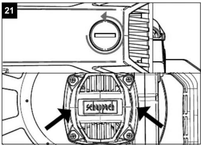
10.4 Brush inspection
Check the carbon brushes after the first 50 operating hours with a new machine, or when new brushes have been fitted. After carrying out the first check, repeat the check every 10 operating hours.
If the carbon is worn to a length of 6 mm, or if the spring or contact wire are burned or damaged, it is necessary to replace both brushes. If the brushes are found to be usable following removal, it is possible to reinstall them.
When servicing the carbon brushes, open the two latches counterclockwise (as shown in Figure 21).
Then remove the carbon brushes.
Replace the carbon brushes in the reverse order.
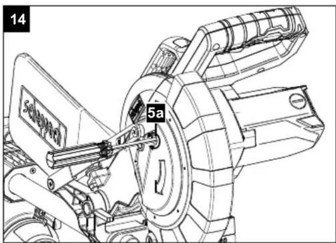
10.5 Changing the saw blade (fig. 1/2/14-17)
Remove the power plug!
Important!
Wear safety gloves when changing the saw blade. Risk of injury!
- Swing the machine head (4) upwards and lock with the locking bolt (23).
- Loosen the retaining screw (5a) of the cover using a Phillips screwdriver.
WARNING!
Do not fully remove this screw (fig. 14).
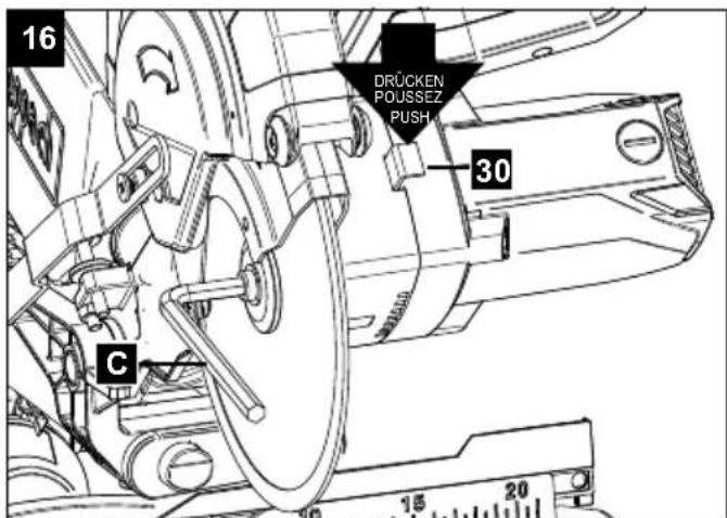
- Fold the saw blade guard (5) upwards until the saw blade guard (5) is above the flange screw (28).
- With one hand insert the Allen key (C) in the flange screw (28).
- Hold the Allen key (C) and slowly close the saw blade guard (5) until it touches the Allen key (C).
- Firmly press the saw shaft lock (30) and slowly rotate the flange screw (28) in clockwise direction. The saw shaft lock (30) engages after no more than one rotation.
- Now, using a little more force, slacken the flange screw (28) in the clockwise direction.
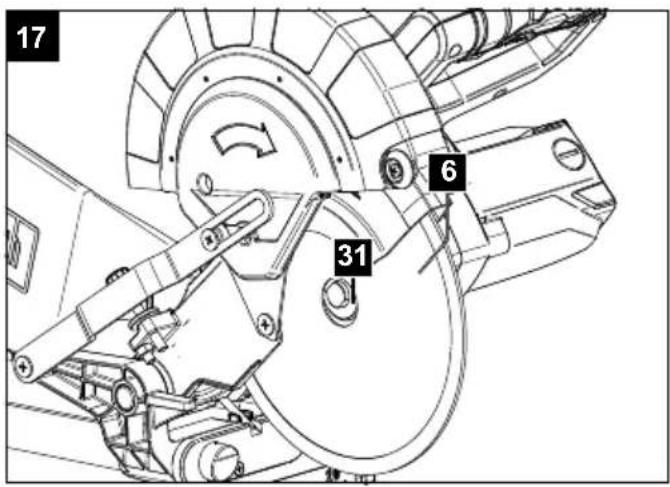
- Turn the flange screw (28) right out and remove the outer flange (29).
• Take the blade (6) off the inner flange (31) and pull out downwards.
- Carefully clean the flange screw (28), outer flange (29) and inner flange (31).
• Fit and fasten the new saw blade (6) in reverse order.
- Fold the saw blade guard (5) downwards until the saw blade guard (5) engages in the locking screw (5a).
• Re-tighten the locking screw (5a).
- Important!
The cutting angle of the teeth, in other words the direction of rotation of the saw blade (6) must coincide with the direction of the arrow on the housing.
- Before continuing your work make sure that all safety devices are in good working condition.
- Important!
Every time that you change the saw blade (6), check to see that it spins freely in the table insert (10) in both perpendicular and 45° angle settings.
- Important!
The work to change and align the saw blade (6) must be carried out correctly.
10.6 Adjusting the laser (fig. 19-20)
If the laser (32) ceases to indicate the correct cutting line, you can readjust the laser. To do so, open the screws (32b) and remove the front cover (32a). Loosen the Phillips head screws (E). Set the laser by moving sideways until the laser beam strikes the teeth of the saw blade (6).
After adjusting and tightening the laser, mount the front cover by tightening both screws (32b) by hand.
The machine must be connected to the mains in order to adjust the laser.
Attention!
Never press the ON/OFF switch (2) when adjusting the laser. Danger of injury!
10.7 Service information
Please note that the following parts of this product are subject to normal or natural wear and that the following parts are therefore also required for use as consumables.
Wear parts*: carbon brushes, saw blade, table insert (art. no. 5901215010), saw dust bag
* Not necessarily included in the scope of delivery!
Spare parts and accessories can be obtained from our Service Centre. Spare parts and accessories can be obtained from our Service Centre.
11. Transport
- Tighten the handle (11) to lock the rotary table.
- Press the machine head (4) downwards and secure with the locking bolt (23).
- Fix the saw's drag function with the locking screw for drag guide (20) in rear position.
- Carry the equipment by the fixed saw table (15).
- When reassembling the equipment proceed as described under section 8 and 9.
12. Storage
Store the device and its accessories in a dark, dry and frost-proof place that is inaccessible to children. The optimum storage temperature is between 5 and 30°C. Store the electrical tool in its original packaging.
Cover the electrical tool in order to protect it from dust and moisture.
Store the operating manual with the electrical tool.
13. Electrical connection
The electrical motor installed is connected and ready for operation. The connection complies with the applicable VDE and DIN provisions. The customer's mains connection as well as the extension cable used must also comply with these regulations.
- The product meets the requirements of EN 61000-3-11 and is subject to special connection conditions. This means that use of the product at any freely selectable connection point is not allowed.
- Given unfavourable conditions in the power supply the product can cause the voltage to fluctuate temporarily.
- The product is intended solely for use at connection points where the following prerequisites apply:
a) A maximum permitted supply impedance "Z" (Zmax = 0.339 Ω) must not be exceeded.
b) A continuous current-carrying capacity of the mains of at least 100 A per phase must be given. - As the user, you are required to ensure that the connection point at which you wish to operate the product meets one of the two requirements, a) or b), mentioned above. As necessary, consult your electric power company.
Important information
In the event of an overloading the motor will switch itself off. After a cool-down period (time varies) the motor can be switched back on again.
Damaged electrical connection cable
The insulation on electrical connection cables is often damaged.
This may have the following causes:
• Passage points, where connection cables are passed through windows or doors.
- Kinks where the connection cable has been improperly fastened or routed.
- Places where the connection cables have been cut due to being driven over.
• Insulation damage due to being ripped out of the wall outlet.
• Cracks due to the insulation ageing.
Such damaged electrical connection cables must not be used and are life-threatening due to the insulation damage.
Check the electrical connection cables for damage regularly. Make sure that the connection cable does not hang on the power network during the inspection.
Electrical connection cables must comply with the applicable VDE and DIN provisions. Only use connection cables of the same designation.
The printing of the type designation on the connection cable is mandatory.
If the power cord of this device is damaged, it must be replaced by a special power cord, which is available from the manufacturer or its service department.
AC motor:
• The mains voltage must be 220 - 240 V\~.
- Extension cables up to 25 m long must have a cross-section of 1.5 mm ^4 .
Connection type X
If the mains connection cable of this device is damaged, it must be replaced by a special connection cable which can be obtained from the manufacturer or its service department.
Connections and repairs of electrical equipment may only be carried out by an electrician.
Please provide the following information in the event of any enquiries:
• Type of current for the motor
• Machine data - type plate
14. Disposal and recycling
Notes for packaging


The packaging materials are recyclable. Please dispose of packaging in an environmentally friendly manner.
Notes on the electrical and electronic equipment act [ElektroG]
Waste electrical and electronic equipment does not belong in household waste, but must be collected and disposed of separately!
- Used batteries or rechargeable batteries that are not installed permanently in the old appliance must be removed non-destructively before disposal. Their disposal is regulated by the battery law.
- Owners or users of electrical and electronic devices are legally obliged to return them after use.
- The end user is responsible for deleting their personal data from the old device being disposed of!
- The symbol of the crossed-out dustbin means that waste electrical and electronic equipment must not be disposed of with household waste.
- Waste electrical and electronic equipment can be handed in free of charge at the following places:
- Public disposal or collection points (e.g. municipal works yards)
- Points of sale of electrical appliances (stationary and online), provided that dealers are obliged to take them back or offer to do so voluntarily.
- Up to three waste electrical devices per type of device, with an edge length of no more than 25 centimetres, can be returned free of charge to the manufacturer without prior purchase of a new device from the manufacturer or taken to another authorised collection point in your vicinity.
- Further supplementary take-back conditions of the manufacturers and distributors can be obtained from the respective customer service.
- If the manufacturer delivers a new electrical appliance to a private household, the manufacturer can arrange for the free collection of the old electrical appliance upon request from the end user. Please contact the manufacturer's customer service for this.
- These statements only apply to devices installed and sold in the countries of the European Union and which are subject to the European Directive 2012/19/EU. In countries outside the European Union, different regulations may apply to the disposal of waste electrical and electronic equipment.
15. Troubleshooting
| Fault Possible cause Remedy | ||
| Motor does not work Motor, cable or plug defective, fuses burnt | Arrange for inspection of the machine by a specialist.Never repair the motor yourself. Danger!Check fuses and replace as necessary | |
| The motor starts up slowly and does not reach operating speed. | Voltage too low, coils damaged, capacitor burnt | Have an electrician check the voltage.Arrange for inspection of the motor by a specialist. Arrange for replacement of the capacitor by a specialist |
| Motor makes excessive noise | Coils damaged, motor defective | Arrange for inspection of the motor by a specialist |
| The engine does not reach full power. | Circuits in the network are overloaded (lamps, other motors, etc.) | Do not use any other equipment or motors on the same circuit |
| Motor overheats easily. | Overloading of the motor, insufficient cooling of the motor | Avoid overloading the motor while cutting, remove dust from the motor in order to ensure optimal cooling of the motor |
| Saw cut is rough or wavy | Saw blade dull, tooth shape not appropriate for the material thickness | Re-sharpen saw blade and/or use suitable saw blade |
| Workpiece pulls away and/ or splinters | Excessive cutting pressure and/ or saw blade not suitable for use | Insert suitable saw blade |
Günzburger Straße 69
D-89335 Ichenhausen
Cher client,
Günzburger Straße 69
D-89335 Ichenhausen
Egregio cliente,
Günzburger Straße 69
D-89335 Ichenhausen
Geachte klant,
Günzburger Straße 69
D-89335 Ichenhausen
Estimado cliente:
Günzburger Straße 69
D-89335 Ichenhausen
Estimado cliente,
Günzburger Straße 69
D-89335 Ichenhausen
Vážený zákazníku,
Günzburger Straße 69
D-89335 Ichenhausen
Vážený zákazník,
Günzburger Straße 69
D-89335 Ichenhausen
Kedves Ügyfelünk!
Günzburger Straße 69
D-89335 Ichenhausen
Szanowny Kliencie,
Günzburger Straße 69
D-89335 Ichenhausen
Poštovani kupci,
Günzburger Straße 69
D-89335 Ichenhausen
Spoštovani kupec,
želimo vam veliko veselja in uspeha pri delu z vašo novo napravo.
Napotek:
Negotovost K_WA 3 dB
Günzburger Straße 69
D-89335 Ichenhausen
Austatud klient!
Günzburger Straße 69
D-89335 Ichenhausen
Gerbiamas kliente,
Günzburger Straße 69
D-89335 Ichenhausen
Godātais klient!
Günzburger Straße 69
D-89335 Ichenhausen
Bästa Kund!
Günzburger Straße 69
D-89335 Ichenhausen
Arvoisa asiakas
Günzburger Straße 69
D-89335 Ichenhausen
Kære kunde,
• 2 x emnesupport (8) (formonteret)
- Spånpose (17)
- Unbrakonøgle 6 mm (C)
- Unbrakonøgle 3 mm (D)
- Brugsanvisning
4. Tilsigtet brug
Günzburger Straße 69
D-89335 Ichenhausen
Kjære kunde,
Günzburger Straße 69
D-89335 Ichenhausen, Германия
Уважаеми клиенти,
Günzburger Straße 69
D-89335 Ichenhausen
Αξιότιμε πελάτη,
Günzburger Straße 69
D-89335 Ichenhausen
Stimate client,
Günzburger Straße 69
D-89335 Ichenhausen
Poštovani kupče,
Günzburger Straße 69
D-89335 Ichenhausen
ithalatçı:
Scheppach GmbH, Günzburger Str. 69, 89335 Ichenhausen
| DE | EU-KonformitätserklärungÜbersetzung der OriginalkonformitätserklärungWir erklären in alleiniger Verantwortung, dass das hier beschriebene Produkt mit den geltenden Richtlinien und Normen übereinstimmt. | Der hier beschriebene Gegenstand der Erklärung erfüllt die Vorschriften der Richtlinie 2011/65/EU des Europäischen Parlaments und des Rates vom 8. Juni 2011 zur Beschränkung der Verwendung bestimmter gefährlicher Stoffe in Elektro- und Elektronikgeräten.*Technische Unterlagen verfügbar bei: ** | ||
| Artikelnummer*** | Artikelbezeichnung: Kapp-, Zug- und Gehrungssäge HM216SPX / MS216 / HM216X | Marke**** | ||
| GB | EU Declaration of ConformityTranslation of the original Declaration of ConformityWe declare under our sole responsibility that the product described here complies with the applicable directives and standards. | The object of the declaration described here fulifiis the regulations of the directive 2011/65/EU of the European Parliament and Council from 8th June 2011, on the restriction of the use of certain hazardous substances in electrical and electronic equipment.*Technical documentation available at: ** | ||
| Item number*** | Item designation: Sliding cross-cut mitre saw HM216SPX / MS216 / HM216X | Brand**** | ||
| FR | Déclaration UE de conformitéTraduction de la déclaration de conformité originaleNous déclarons, sous notre propre responsabilité, que le produit décrit ici est conforme aux directives et normes en vigueur. | L'appareil décrit ci-dessus dans la déclaration est conforme aux réglementations de la directive 2011/65/EU du Parlement Européen et du Conseil du 8 juin 2011 visant à limiter l'utilisation de substances dangereuses dans la fabrication des appareils électriques et électroniques.*Dossier technique auprès de: ** | ||
| Référence *** | Désignation de l'article: Scie à onglet radiale HM216SPX / MS216 / HM216X | Marque **** | ||
| IT | Dichiarazione di conformità UETraduzione della dichiarazione di conformità originaleDichiariamo sotto la nostra esclusiva responsabilità che il prodotto qui descritto è conforme alle direttive e alle norme vigenti. | L'oggetto della dichiarazione, qui descritto, soddisfa le disposizioni della Direttiva 2011/65/UE del Parlamento Europeo e del Consiglio dell'8 giugno 2011, sulla restrizione nell'utilizzo di determinate sostanze pericolose negli apparecchi elettrici ed elettronici.*Documentazione tecnica disponibile presso: ** | ||
| Gaminio numeris *** | Nome articolo: Sega troncatrice, a trazione e per tagli obliqui HM216SPX / MS216 / HM216X | Marchio **** | ||
| NL | EU-conformiteitsverklaringVertaling van de originele conformiteitsverklaringWij verklaren onder eigen verantwoordelijkheid dat het hier beschreven pro-duct voldoet aan de geldende richtlijnen en normen. | Het hier beschreven onderwerp van deze verklaring voldoet aan de voorschriften van richtlijn 2011/65/EU van het Europese Parlement en de Raad van 8 juni 2011 omtrent de beperking van het gebruik van bepaalde gevaarlijke stoffen in elektrische en elektronische apparaten.*Technische documentatie verkrijgbaar bij: ** | ||
| Artikelnummer *** | Artikelnaam: Afkort-, trek- en verstekzaag HM216SPX / MS216 / HM216X | Merk **** | ||
| ES | Declaración de conformidad UETraducción de la Declaración de conformidad originalDeclaramos, bajo nuestra exclusiva responsabilidad, que el producto aquí descrito cumple las directivas y normas aplicables. | El objeto de la declaración aquí descrito cumple las disposiciones de la Directiva 2011/65/UE del Parlamento Europeo y el Consejo del 8 de junio de 2011 sobre restricciones a la utilización de determinadas sustancias peligrosas en aparatos eléctricos y electrónicos.*Documentación técnica disponible en: ** | ||
| Núm. de artículo*** | Denominación del artículo: Sierra tronzadora, de tracción y de cortar ingletes HM216SPX / MS216 / HM216X | Marca**** | ||
| PT | Declaração de conformidade UETradução da declaração de conformidade originalDeclaramos, à nossa exclusiva responsabilidade, que o produto aqui descri-to está em conformidade com as diretivas e normas aplicáveis. | O objeto da declaração aqui descrito cumpre com as normas da Diretiva 2011/65/UE do Parlamento Europeu e do Conselho de 8 de junho de 2011 relativamente à restrição da utilização de determinadas substâncias perigosas em equipamentos elétricos e eletrônicos.*Documentos técnicos disponíveis junto de: ** | ||
| Número de artigo*** | Designação do artigo: Serra de esquadria, de traçar e angular HM216SPX / MS216 / HM216X | Marca**** | ||
| CZ | EU prohlásení o shoděPřeklad originálního prohlásení o shoděProhlášujeme na svou výlučnou odpovědnost, že zde popsaný výrobek od-povídá platným směmicím a normám. | Zde popsaný předmět prohlásení splňuje předpisy směrnice 2011/65/EU Evrop-ského parlamentu a Rady ze dne 8. června 2011 pro omezení používání určitých nebezpečných látek v elektrických a elektronických zařízeních.*Technické podklady k dispozici u: ** | ||
| Číslo výrobku*** | Název výrobku: Kapovací, dvouruční pila a pila na pokos HM216SPX / MS216 / HM216X | Značka**** | ||
| SK | EÚ vyhlásenie o zhodePreklad originálneho vyhlásenia o zhodeNa vlastnú zodpovednosť vyhlasujeme, že tu poplsaný výrobok je v súlade s platnými smernicami a normami. | Tu opísany predmet vyhlásenia je v súlade s predpismi smernice Európskehó parlamentu a Rady 2011/65/EU z 8. júna 2011 o obmedzení používania určitých nebezpečných látok v elektrických a elektronických zariadeniach.*Technické podklady sú k dispozicii na: ** | ||
| Číslo výrobku *** | Označenie výrobku: Skracovacia, dvojručná a pokosová pila HM216SPX / MS216 / HM216X | Značka **** | ||
| HU | EU megfelelőségi nyilatkozatAz eredeti megfelelőségi nyilatkozat fordításaSaját kizárólagos felelősségünkre kijelentjük, hogy az itt ismertetett termék megfelel az érvényes irányelveknek és szabványoknak. | A nyilatkozat itt megnevezett tárgya teljesíti az Európai Parlament és Tanács 2011. június 8-i, egyes veszélyes anyagok elektromos és elektronikus berendezésekeb n való alkalmazásának korlátozásáról szóló 2011/65/EU irányelvének előirásait.*A můszaki dokumentáció elérhető: ** | ||
| Cikkszám *** | Termék megnevezése: Fejező, vonó- és gérvágó fűrész HM216SPX / MS216 / HM216X | Márka **** | ||
| PL | Deklaracja zgodności UETłumaczenie oryginalnej deklaracji zgodnościOświadczamy na własną odpowiedzialność, że opisany tutaj produkt jest zgodny z obowiązującymi dyrektywami i normami. | Wymieniony powyżej przedmiot niniejszej deklaracji jest zgodny z wymogami dyrektywy 2011/65/UE Parlamentu Europejskiego i Rady z 8 czerwca 2011 r. w sprawie ograniczenia stosowania niektórych niebezpiecznych substancji w sprzęcie elektrycznym i elektronicznym.*Dokumentacja techniczna dostępna na stronie: ** | ||
| Numer artykułu *** | Nazwa artykułu: Pilarka przesuwna do cięcia kątowego i ukośnego HM216SPX / MS216 / HM216X | Marka **** | ||
| HR | EU izjava o sukladnostiPrijevod originalne izjave o sukladnostiNa svoju odgovornost izjavljujemo da je ovdje opisan proizvod usklađen s važećim direktivama i normama. | Ovdje opisani predmet Izjave ispunjava propise Direktive 2011/65/EU Europskog parlamenta i Vijeća od 8. lipnja 2011. o ograničenju uporabe određenih opasnih tvari u električnoj i elektroničkoj opremi.*Tehnička dokumentacija dostupna je na: ** | ||
| Broj artikla*** | Naziv artikla: Presječna, vlačna i kutna pila HM216SPX / MS216 / HM216X | Marka**** | ||
| SI | EU izjava o skladnostiPrevod originalne izjave o skladnostiS polno odgovornostjo izjavljamo, da je tukaj opisani izdelek v skladu z ve- ljavnimi smernicami in standardi. | Tukaj opisani predmet izjave izpolnjuje predpise Direktive 2011/65/EU Evrop- skega parlamenta in Sveta z dne 8. junij 2011 za omejevanje uporabe določenih nevarnih snovi v električnih in elektronskih napravah.*Tehnični dokumenti so na voljo pri: ** | ||
| Številka izdelka *** | Opis izdelka: Čelilna, vlečna in zajeralna žaga HM216SPX / MS216 / HM216X | Znamka **** | ||
| EE | EL vastavusdeklaratsioonVastavusdeklaratsiooni originaali tõlgeMe deklareerimine ainuisikuliselt vastutades, et siin kirjeldatud toode ühtib esitatud direktiivide ja normidega. | Deklaratsiooni objektiks olev siin kirjeldatud ese vastab Euroopa Parlamendi ja nõukogu direktiivile 2011/65/EÜ kuupäevaga 8. juuni 2011 teatud ohtlike aineke kasutamispiirangu kohta elektri- ja elektroonikaseadmetes.*Tehnilised dokumentid on saadaval: ** | ||
| Artiklinumber *** | Art nimetus: Otsamis-, tömbe ja eerungisaag HM216SPX / MS216 / HM216X | Kaubamärk **** | ||
| LT | EB atitikties deklaracijaAtitikties deklaracijos originalo vertimasPrisiimdami išskirtinę atsakomybę deklaruojame, kad čia aprašytas gami- nys atitinka galiojančias direktyvas ir standartus. | Čia aprašytas deklaracijos objektas atitinka 2011 m. birželio 8 d. Europos Parla- mento ir Tarybos direktyvos 2011/65/ES dėl tam tikru pavojingų medžiagų nau- dojimo elektrôs ir elektroninėje jrangoje apribojimo reikalavimus.*Techninius dokumentus galima gauti iš: ** | ||
| Gaminio numeris *** | Gaminio pavadinimas: Dvirankis skersinio ir jstrižinio pjaustymo pjūklas HM216SPX / MS216 / HM216X | Prekės ženklas **** | ||
| LV | ES atbilstības deklarācijaOriginālās atbilstības deklarācijas tulkojumsMės, uzņemoties pilnu atbildību, paziņojam, ka šeit aprakstītais ražojums atbilst spēkā esošajām direktiivām un standartiem. | Šeit aprakstītais deklarācijas priekšmets atbilst Eiropas Parlamenta un Eiropas Padomes 2011. gada 8. jūnija Direktīvas 2011/65/ES noteikumiem par noteiktu bīstamo vielu izmantošanas ierobežošanu elektriskajās un elektroniskajās ie- ricės.*Tehniskā lieta ir pieejama pie: ** | ||
| Preces numurs *** | Preces apzīmējums: Sagarumošanas zāgis, škērszāgls un lenkzāgls HM216SPX / MS216 / HM216X | Prečzīme **** | ||
| SE | EU-försäkran om överensstämmelseÖversättning från försäkran om överensstämmelse i originalVi förklarar under eget ansvar att produkten som beskrivs här överensstäm- mer med gällande riktlinjer och standarder. | Föremålet för försäkran som beskrivs här överensstämmer med bestämmelser- na i Europaparlamentets och rādets direktiv 2011/65/EU av den 8 juni 2011 om begränsning av användningen av vissa farliga ämnen i elektriska och elektr- niska produkter.*Teknisik dokumentation tillgänglig hos: ** | ||
| Artikelnummer *** | Artikelbeteckning: Kap-, drag- och geringsság HM216SPX / MS216 / HM216X | Märke **** | ||
| FI | EU-vaatimustenmukaisuusvakuutusAlkuperäisen vaatimustenmukaisuusvakuutuksen käännösVakuutamme omalla vastuullamme, että tässä kuvattu tuote täyttää voimas- sa olevien direktiivien ja standardien määräykset. | Tässä kuvattu vakuutuksen kohde täyttää tiettyjen vaarallisten aineiden käytön rajoittamisesta sähkö- ja elektronikkalaitteissa 8. kesäkuuta 2011 annetun Eu- roopan parlamentin ja neuvoston direktiivin 2011/65/EU määräykset.*Tekniset asiakirjat saatavana: ** | ||
| Tuotenro *** | Tuotenimike: Katkaisu-, liuku- ja viistesaha HM216SPX / MS216 / HM216X | Merkki **** | ||
| DK | EU-overensstemmelseserklæringOversættelse af den originale overensstemmelseserklæringVi erklærer under eget ansvar, at det her beskrevne produkt overholder de gæl- dende direktiver og standarder. | Genstanden for den her beskrevne erklæring overholder bestemmelseerne i Europa-Parlamentets og Radets direktiv 2011/65/EU af 8. juni 2011 vedr. be- grænsing af brugen af visse farlige stoffer i elektrisk og elektronisk udstyr.*Tekniske dokumenter findes på: ** | ||
| Artikelnummer *** | Art.-betegnelse: Kap-, træk- og geringssav HM216SPX / MS216 / HM216X | Mærke **** | ||
| NO | EU-samsvarserklæringOversettelse av den opprinnelige samsvarserklæringenVi erklærer med enansvar at produktet som er beskrevet her er i samsvar med gjeldende direktiver og standarder. | Gjenstand for erklæringen beskrevet her oppfyller forskriftene til direktiv 2011/65/EU fra Europa-Parlamentel og Rådet av 8. juni 2011 om begrensning av bruken av bestemte farlige stoffer i elektronikk og elektronisk utstyr.*Tekniske dokumenter tilgjengelig hos: ** | ||
| Artikkelnummer *** | Art.betegnelse: Kapp-, trekk- og gjæringssag HM216SPX / MS216 / HM216X | Merke **** | ||
| BG | ЕС Декларация за съответствиеПревод на оригиналната декларация насъответствиеНие декларираме на своя отговорност, че описаният тук продукт отговаря на приложимите директиви и стандарти. | Описаният предмет в декларацията отговаря на разпоредбите на Дирек-тива 2011/65/ЕС на Европейския парламент и на Съвета от 8 юни 2011 г.относно ограничението на употребата на определени опасни вещества велектрическото и електронното оборудване.*Техническата документация се предоставя от: ** | ||
| Каталожен номер *** | Обозначение на артикула: Циркулярен трион с изтегляне и герунг НМ216SPX / MS216 / НМ216Х | Марка **** | ||
| GR | Дήλωση συμμόρφωσης ЕЕМетάфраση από το πρωτότυπο της δήλωσης συμμόρφωσηςДηλώνουμε με αποκλειστική μας ευθύνη ότι το προϊόν που περιγράφεται στο παρόν βρίσκεται σε συμμόρφωση με τις ισχύουσες Оδηγίες και Прό-тупа. | To αντικείμενο της παρούσας δήλωσης, то оптою περιγράφεται εδώ, ектпл-ρώνει τις διατάξεις της Оδηγίας 2011/65/ΕΕ του Еυρωταϊκού Κοινοβουλίου και του Συμβουλίου της 8ης Ιουνίου 2011 σχετικά με τον περιορισμό της χρήσης ορισμένων επτικίνδυνων ουσιών σε ηλεκτρικό και ηλεκτρονικό εξοπλισμό.*Ο τεχνικός φάκελος είναι διαθέσιμος στη θέση: ** | ||
| Аріθμός είδους *** | Овомаσία είδ.: Δισκοπρίονο κάθετης κοπής, συρόμενης κοπής - фалтσοπρίονο НМ216SPX / MS216 / НМ216Х | Мáрка **** | ||
| RO | Declaratie de conformitate UETraducere a declarației de conformitate originaleDeclarăm pe proprie răspundere că produsul descris aici coincide cu direc-tivele și normele în vigoare. | Obiectul declarației descris aici îndeplinește prescripțiile directivei 2011/65/UE a Parlamentului European și a Consiliului din 8 lunie 2011 asupra limitării utilizării anumitor substanțe periculoase în aparatele electrice și electronice.*Documentație tehnică disponibilă la: ** | ||
| Număr articol *** | Notație art.: Ferăstrău pentru retezare, ferăstrău-joagăr și pentru îmbinări de colț НМ216SPX / MS216 / НМ216Х | Marcă **** | ||
| RS | EU izjava o usaglašenostiPrevod originalne izjave o usklađenostiIzjavljujemo na našu isključivu odgovomost da je ovde opisani proizvod usk-lađen sa primenljivim smernicama i standardima. | Ovde opisani predmet ove izjave ispunjava odredbe Direktive 2011/65/EU Evropskog parlamenta i Saveta od 8. juna 2011. godine o ograničenju upotrebe određenih opasnih materija u električnoj i elektronskoj opremi.*Tehnička dokumentacija dostupna kod: ** | ||
| Broj artikla *** | Oznaka proizvoda: Preklopna, potezna i ugaona testera НМ216SPX / MS216 / НМ216Х | Brend **** | ||
| TR | AB uygunluk beyaniOrijinal uygunluk beyanının çevirisiBurada açıklanan ürünün geçerli yönetmeliklere ve standartlara uygun oldu-ğunu tamamen kendi sorumluluğumuz altında beyan ediyoruz. | Işbu uygunluk beyanının düzenlendiği burada adı geçen ürün, Avrupa Parlamen-tosu’nun ve 8 Haziran 2011 tarihli Konsey’in elektrik ve elektronik cihazlarda belirli tehlikeli maddelerin sınırlandırılması ilişkin 2011/65/AT sayılı direktifini yerine getirmektedir.*Teknik belgeler şurada mevcuttur: ** | ||
| Ürün numarası *** | Ürün Tanım: Gönye, iki kollu ve gönyeburun testeresi НМ216SPX / MS216 / НМ216Х | Marka **** | ||
| ***5901221901 / 5901221905 / 59012219969 / 59012159968 / 5901221904 | ****SCHEPPACH | |||
| **:Matthias HerzGünzburger Str. 69D-89335 Ichenhauseni.V.Andreas Pecher /Head of Project Managementi.V. Andreas Pecher / Division Manager Product CenterIchenhausen, 17.06.2025 | X 2011/65/EU*X 2014/30/EU□ 2016/1628/EU□ 2014/29/EU□ 2014/35/EU□ 2004/22/EG□ 2014/68/EU□ 89/686/EWG_96/58/EG□ 90/396/EWG | X 2006/42/EG□ Annex IVNotified Body:Notified Body No.:Certificate No.: | □ 2000/14/EG; 2005/88/EG Noise:measured L_WA = xx dBguaranteed L_WA = xx dB□ Annex V□ Annex VINotified Body:Notified Body No.: |
| □ 2016/1628/EUEmission No.: | |||
| EN 62841-1:2015/A11:2022; EN IEC 62841-3-9:2020/A11:2020; EN IEC 55014-1:2021;EN IEC 55014-2:2021;EN IEC 61000-3-2:2019/A1:2021; EN IEC 61000-3-11:2019 | |||
Garantie DE
Apparent defects must be notified within 8 days from the receipt of the goods. Otherwise, the buyer loses its rights of claim due to such defects are invalidated. We guarantee for our machines in case of proper treatment for the time of the statutory warranty period from delivery in such a way that we replace any machine part free of charge which provably becomes unusable due to faulty material or defects of fabrication within such period of time. With respect to parts not manufactured by us we only warrant insofar as we are entitled to warranty claims against the upstream suppliers. The costs for the installation of the new parts shall be borne by the buyer. The cancellation of sale or the reduction of purchase price as well as any other claims for damages shall be excluded.
Garantie FR
Apparent defects must be notified within 8 days from the receipt of the goods. Otherwise, the buyer's rights of claim due to such defects are invalidated. We guarantee for our machines in case of proper treatment for the time of the statutory warranty period from delivery in such a way that we replace any machine part free of charge which provably becomes unusable due to faulty material or defects of fabrication within such period of time. With respect to parts not manufactured by us we only warrant insofar as we are entitled to warranty claims against the upstream suppliers. The costs for the installation of the new parts shall be borne by the buyer. The cancellation of sale or the reduction of purchase price as well as any other claims for damages shall be excluded.
Záruka CZ
Apparent defects must be notified within 8 days from the receipt of the goods. Otherwise, the buyer is rights of claim due to such defects are invalidated. We guarantee for our machines in case of proper treatment for the time of the statutory warranty period from delivery in such a way that we replace any machine part free of charge which provably becomes unusable due to faulty material or defects of fabrication within such period of time. With respect to parts not manufactured by us we only warrant insofar as we are entitled to warranty claims against the upstream suppliers. The costs for the installation of the new parts shall be borne by the buyer. The cancellation of sale or the reduction of purchase price as well as any other claims for damages shall be excluded.
Garantii EE
Apparent defects must be notified within 8 days from the receipt of the goods. Otherwise, the buyer's rights of claim due to such defects are invalidated. We guarantee for our machines in case of proper treatment for the time of the statutory warranty period from delivery in such a way that we replace any machine part free of charge which provably becomes unusable due to faulty material or defects of fabrication within such period of time. With respect to parts not manufactured by us we only warrant insofar as we are entitled to warranty claims against the upstream suppliers. The costs for the installation of the new parts shall be borne by the buyer. The cancellation of sale or the reduction of purchase price as well as any other claims for damages shall be excluded.