
HWS 810230 Professional - Screwdriver BOSCH - Free user manual and instructions
Find the device manual for free HWS 810230 Professional BOSCH in PDF.
| Product type | Screwdriver |
| Brand | Bosch |
| Model | HWS 810230 Professional |
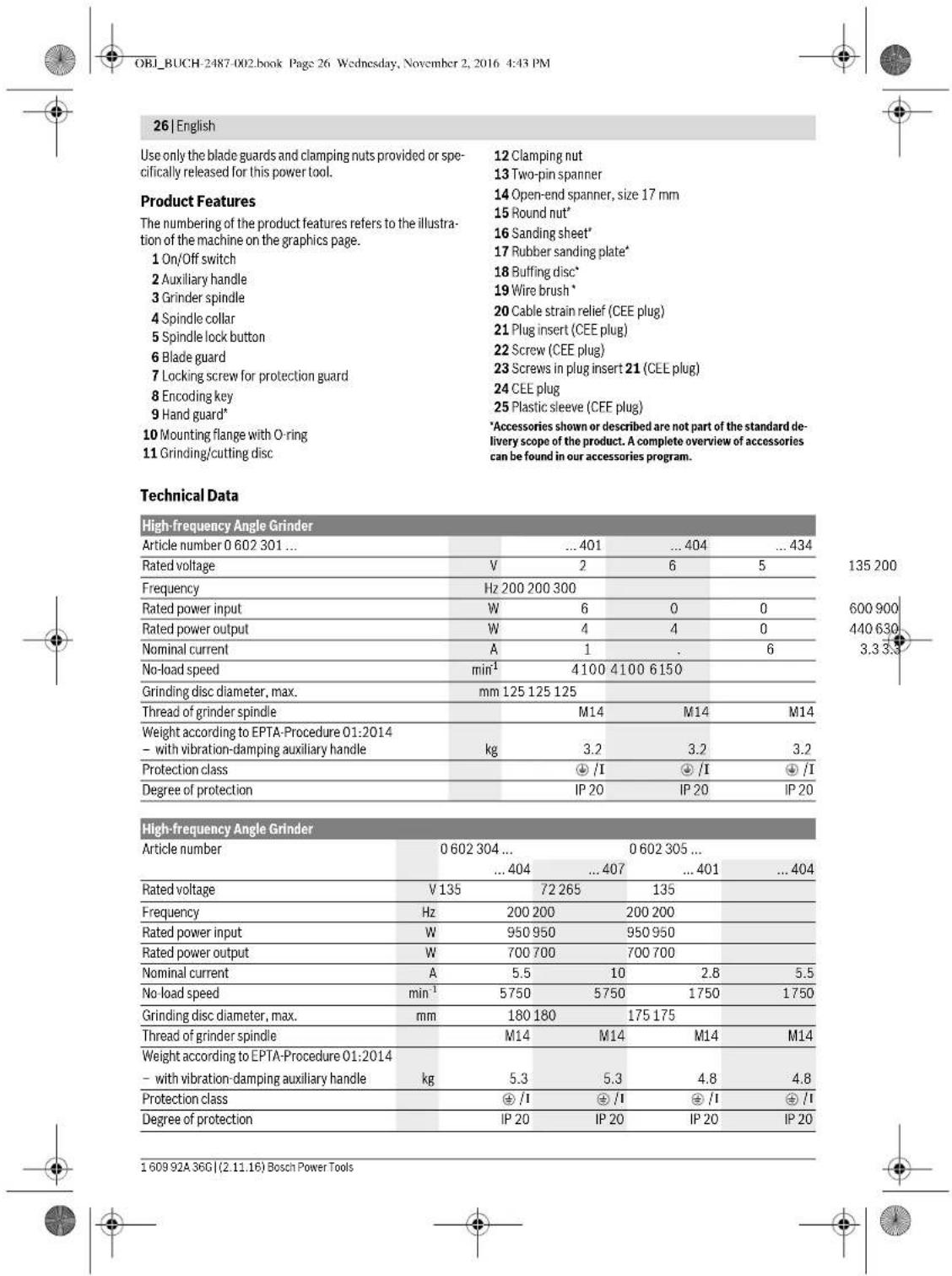
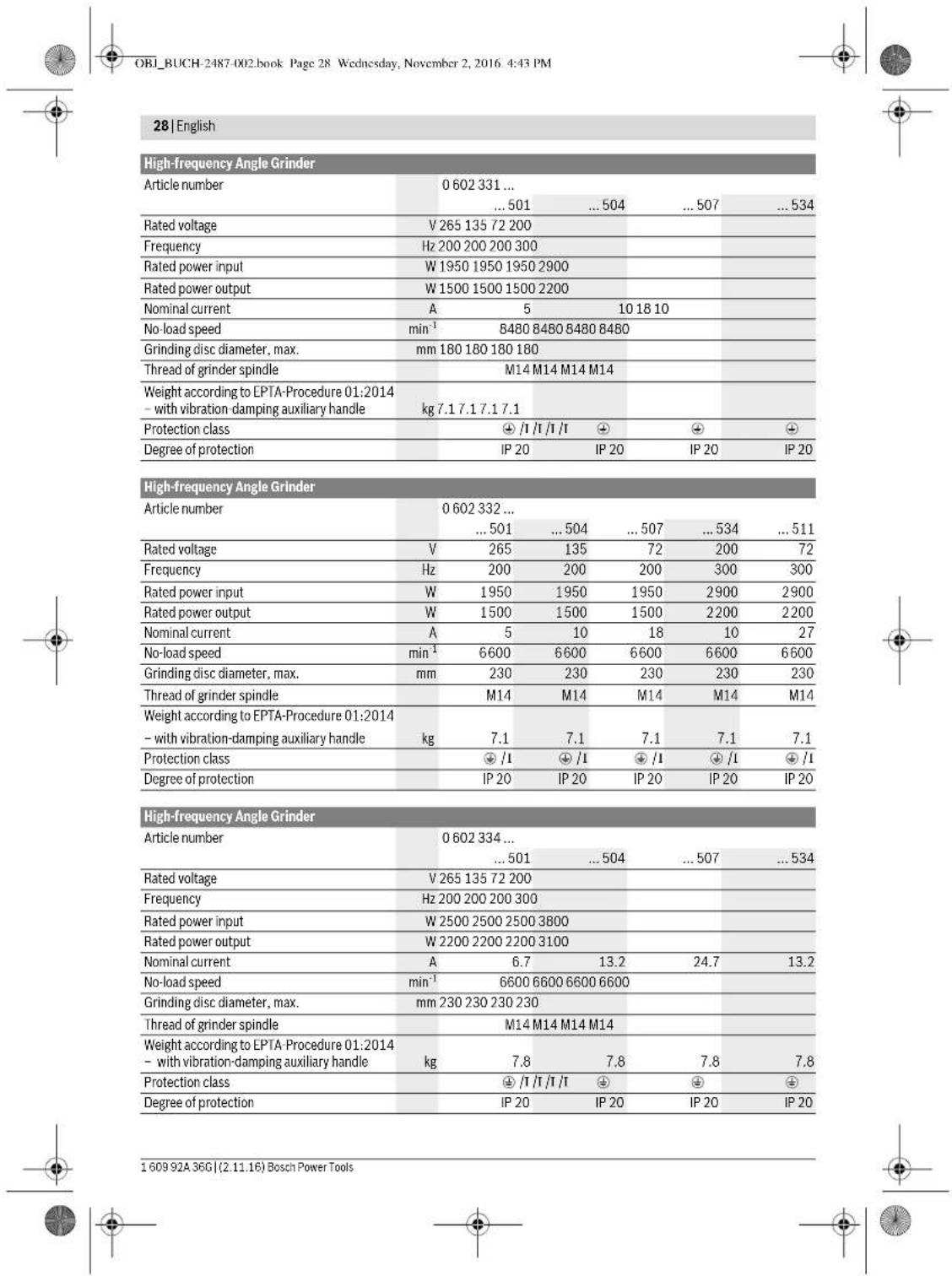
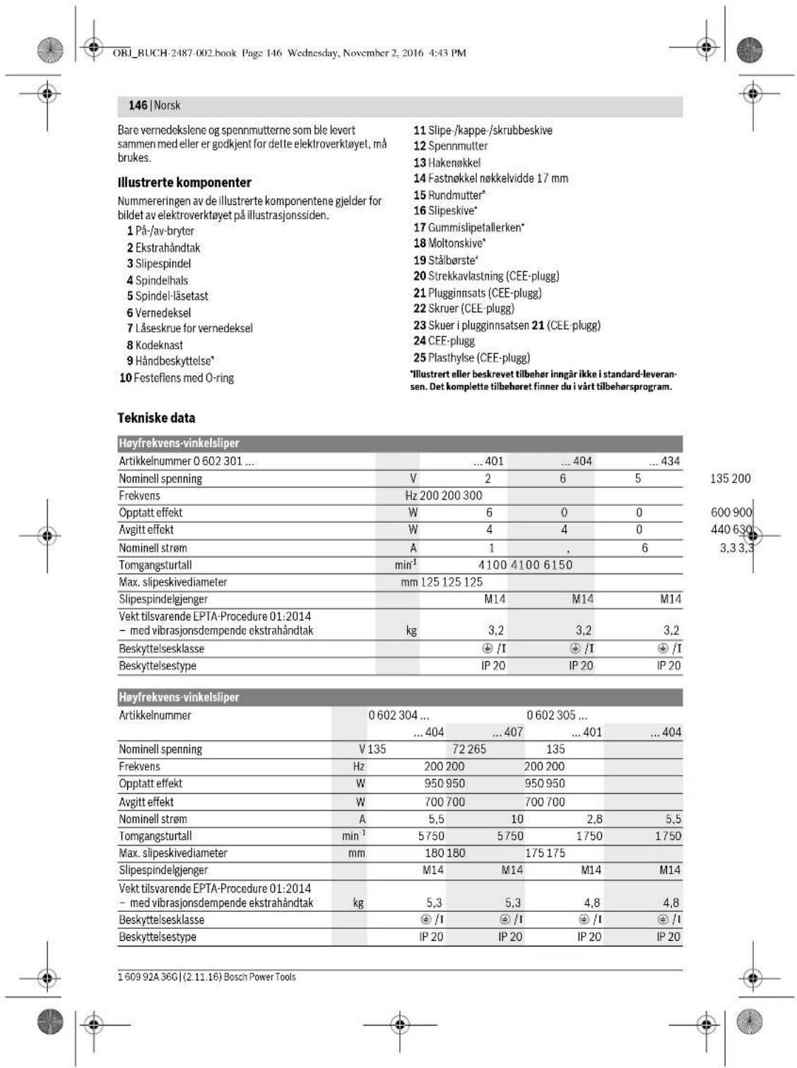
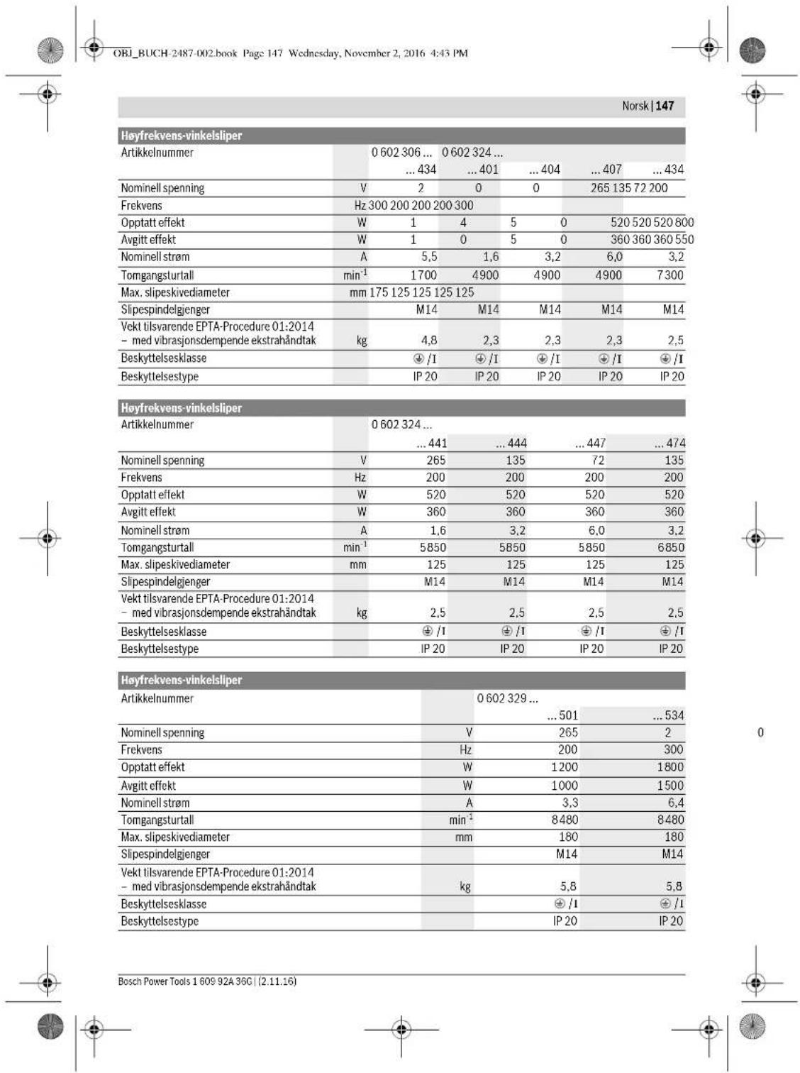
| Supply voltage | 135–265 V (depending on model) |
| Frequency | 200–300 Hz |
| No-load speed | 1750 min⁻¹ or 5750 min⁻¹ (depending on model) |
| Max. disc diameter | 180 mm |
| Spindle thread | M14 |
| Weight | Approx. 2.5 kg |
| Main functions | Grinding, cutting, sanding, brushing, polishing |
| Maintenance and cleaning | Regularly clean the ventilation slots with compressed air. Check the no-load speed and cable condition. |
| Safety | Wear safety glasses, mask, gloves, hearing protection. Use the protective guard and auxiliary handle. Follow anti-kickback instructions. |
| Spare parts and repairability | Repairs only by an authorized Bosch service center. Use original parts and specific cables. |
| General information | Manual available in several languages. Dry use on metals and stone. |
Frequently Asked Questions - HWS 810230 Professional BOSCH
User questions about HWS 810230 Professional BOSCH
0 question about this device. Answer the ones you know or ask your own.
Ask a new question about this device
Download the instructions for your Screwdriver in PDF format for free! Find your manual HWS 810230 Professional - BOSCH and take your electronic device back in hand. On this page are published all the documents necessary for the use of your device. HWS 810230 Professional by BOSCH.
USER MANUAL HWS 810230 Professional BOSCH
BUCH-2487-002. book Page 1 Wednesday, November 2, 2016 4:33 PM
Robert Bosch Power Tools GmbH
70538 Stultgart
GERMANY
www.bosch-pt.com
160992A36G(2015.07)AS/473 EURO

1609 92A 36G
HWS
06023014.060230440.060230540.060230643406023244..
06023295..|06023315..|06023325..|06023345..

BOSCH
no Original drillsin
6 Akuperaisjt object
el npumbrncooryx yphcn
OBI_BUCH-2487-002.book Page 16 Wednesday, November 2, 2016 4:43 PM
16 | Deutsch
Executive Vice President
Head of Product Certification
Engineering
PT/ECS
f_( 2) = h · d
Robert Bosch Power Tools GmbH
70538 Stuttgart,GERMANY
Stuttgart, 01.01.2017
Montage
OBI_BUCH-2487-002.book Page 17 Wednesday, November 2, 2016 4:43 PM
Deutsch 17
OBI_BUCH-2487-002.book Page 18 Wednesday, November 2, 2016 4:43 PM
18 | Deutsch
OBI_BUCH-2487-002.book Page 20 Wednesday, November 2, 2016 4:43 PM
20 | Deutsch
General Power Tool SafetyWarnings
WARNING Read all safety warnings and all instruc-tions. Failure to follow the warnings and instructions may result in electric shock, fire and/or serious injury.
Save all warnings and instructions for future reference. The term "power tool" in the warnings refers to your mains-operated (corded) power tool or battery-operated (cordless power tool.
Work area safety
- Keep work area clean and well lit. Cluttered or dark areas invite accidents.
Do not operate power tools in explosive atmospheres, such as in the presence of flammable liquids, gases or dust. Power tools create sparks which may ignite the dust or fumes. - Keep children and bystanders away while operating a power tool. Distractions can cause you to lose control.
Electrical safety
Power tool plugs must match the outlet. Never modify the plug in any way. Do not use any adapter plugs with earthed (grounded) power tools. Unmodified plugs and matching outlets will reduce risk of electric shock.
- Avoid body contact with earthed or grounded surfaces, such as pipes, radiators, ranges and refrigerators. There is an increased risk of electric shock if your body is earthed or grounded.
Do not expose power tools to rain or wet conditions. Water entering a power tool will increase the risk of electric shock.
Do not abuse the cord. Never use the cord for carrying, pulling or unplugging the power tool. Keep cord away from heat, oil, sharp edges and moving parts. Damaged or entangled cords increase the risk of electric shock.
When operating a power tool outdoors, use an extension cord suitable for outdoor use. Use of a cord suitable for outdoor use reduces the risk of electric shock.
If operating a power tool in a damp location is unavoidable, use a residual current device (RCD) protected supply. Use of an RCD reduces the risk of electric shock.
Personal safety
Stay alert, watch what you are doing and use common sense when operating a power tool. Do not use a power tool while you are tired or under the influence of drugs, alcohol or medication. A moment of inattention while operating power tools may result in serious personal injury.
Use personal protective equipment. Always wear eye protection. Protective equipment such as dust mask, non-skid safety shoes, hard hat, or hearing protection used for appropriate conditions will reduce personal injuries.
Prevent unintentional starting. Ensure the switch is in the off-position before connecting to power source and/or battery pack, picking up or carrying the tool. Carrying power tools with your finger on the switch or energising power tools that have the switch on invites accidents.
Remove any adjusting key or wrench before turning the power tool on. A wrench or a key left attached to a rotating part of the power tool may result in personal injury.
Do not overreach. Keep proper footing and balance at all times. This enables better control of the power tool in unexpected situations.
Dress properly. Do not wear loose clothing or jewellery. Keep your hair, clothing and gloves away from moving parts. Loose clothes, jewellery or long hair can be caught in moving parts.
If devices are provided for the connection of dust extraction and collection facilities, ensure these are connected and properly used. Use of dust collection can reduce dust-related hazards.
Power tool use and care
Do not force the power tool. Use the correct power tool for your application. The correct power tool will do the job better and safer at the rate for which it was designed.
Do not use the power tool if the switch does not turn it on and off. Any power tool that cannot be controlled with the switch is dangerous and must be repaired.
- Disconnect the plug from the power source and/or the battery pack from the power tool before making any adjustments, changing accessories, or storing power tools. Such preventive safety measures reduce the risk of starting the power tool accidentally.
Store idle power tools out of the reach of children and do not allow persons unfamiliar with the power tool or these instructions to operate the power tool. Power tools are dangerous in the hands of untrained users.
Maintain power tools. Check for misalignment or binding of moving parts, breakage of parts and any other condition that may affect the power tool's operation. If damaged, have the power tool repaired before use. Many accidents are caused by poorly maintained power tools.


OBI_BUCH-2487-002.book Page 23 Wednesday, November 2, 2016 4:43 PM
English|23
- Keep cutting tools sharp and clean. Properly maintained cutting tools with sharp cutting edges are less likely to bind and are easier to control.
Use the power tool, accessories and tool bits etc. in accordance with these instructions, taking into account the working conditions and the work to be performed. Use of the power tool for operations different from those intended could result in a hazardous situation.
Service
Have your power tool serviced by a qualified repair person using only identical replacement parts. This will ensure that the safety of the power tool is maintained.
SafetyWarnings for AngleGrinder
Safety warnings common for sanding with sanding discs and polishing
Applies for the following types:
-06023014..
-060230540
-0602306434
-060232440.
This power tool is to be used as a sander and polisher. Observe all safety warnings, instructions, illustrations and data supplied with the power tool. Non-observation of the following instructions can lead to electric shock, fire and/or serious injury.
Operations such as grinding, wire brushing or cutting off are not recommended to be performed with this power tool. Operations for which the power tool was not designed may create a hazard and cause personal injury.
Safety warnings common for grinding, working with wire brushes and cut-off grinding
Applies for the following types:
-060230440
-060232444,..464,..474,..434
-06023295..
-06023315..
-06023325..
-06023345..
This power tool is to be used as a grinder, wire brush and cut off grinder. Observe all safety warnings, instructions, illustrations and data supplied with the power tool. Non-observation of the following instructions can lead to electric shock, fire and/or serious injury.
Operations such as sanding or polishing are not recommended to be performed with this power tool. Operations for which the power tool was not designed may create a hazard and cause personal injury.
Safety warnings that are common for grinding, sanding, wire brushing, polishing and abrasive cutting off operations
Applies for all types
- Do not use accessories which are not specifically designed and recommended by the tool manufacturer. Just because the accessory can be attached to your power tool, it does not assure safe operation.
The rated speed of the accessory must be at least equal to the maximum speed marked on the power tool. Accessories running faster than their rated speed can break and fly apart.
The outside diameter and the thickness of your accessory must be within the capacity rating of your power tool. Incorrectly sized accessories cannot be adequately guarded or controlled.
- Threaded mounting of accessories must match the grinder spindle thread. For accessories mounted by flanges, the armour hole of the accessory must fit the locating diameter of the flange. Accessories that do not match the mounting hardware of the power tool will run out of balance, vibrate excessively and may cause loss of control.
Do not use a damaged accessory. Before each use inspec the accessory such as abrasive wheels for chips and cracks, backing pad for cracks, tear or excess wear, wire brush for loose or cracked wires. If power tool or accessory is dropped, inspect for damage or install an undamaged accessory. After inspecting and installing an accessory, position yourself and bystanders away from the plane of the rotating accessory and run the power tool at maximum no-load speed for one minute. Damaged accessories will normally break apart during this test time.
Wear personal protective equipment. Depending on application, use face shield, safety goggles or safety glasses. As appropriate, wear dust mask, hearing protectors, gloves and shop apron capable of stopping small abrasive or workpiece fragments. The eye protection must be capable of stopping flying debris generated by various operations. The dust mask or respirator must be capable of filtrating particles generated by your operation. Prolonged exposure to high intensity noise may cause hearing loss.
- Keep bystanders a safe distance away from work area. Anyone entering the work area must wear personal protective equipment. Fragments of workpiece or of a broken accessory may fly away and cause injury beyond immediate area of operation.
Hold the power tool by insulated gripping surfaces only, when performing an operation where the cutting accessory may contact hidden wiring or its own cord. Cutting accessory contacting a "live" wire may make exposed metal parts of the power tool "live" and could give the operator an electric shock.
Position the cord clear of the spinning accessory. If you lose control, the cord may be cut or snagged and your hand or arm may be pulled into the spinning wheel.
- Never lay the power tool down until the accessory has come to a complete stop. The spinning wheel may grab the surface and pull the power tool out of your control.
- Do not run the power tool while carrying it at your side. Accidental contact with the spinning accessory could snag your clothing, pulling the accessory into your body.
Bosch Power Tools 1609 92A 36C (2.11.16)


24|English
Regularly clean the power tool's air vents. The motor's fan will draw the dust inside the housing and excessive accumulation of powdered metal may cause electrical hazards.
Do not operate the power tool near flammable materials. Sparks could ignite these materials.
Do not use accessories that require liquid coolants. Using water or other liquid coolants may result in electrocution or shock.
Kickback and related warnings
Kickback is a sudden reaction to a pinched or snagged rotating wheel, backing pad, brush or any other accessory. Pinching or snagging causes rapid stalling of the rotating accessory which in turn causes the uncontrolled power tool to be forced in the direction opposite of the accessory's rotation at the point of the binding. For example, if an abrasive wheel is snagged or pinched by the workpiece, the edge of the wheel that is entering into the pinch point can dig into the surface of the material causing the wheel to climb out or kick out. The wheel may either jump toward or away from the operator, depending on direction of the wheel's movement at the point of pinching. Abrasive wheels may also break under these conditions.
Kickback is the result of power tool misuse and/or incorrect operating procedures or conditions and can be avoided by taking proper precautions as given below.
- Maintain a firm grip on the power tool and position your body and arm to allow you to resist kickback forces. Always use auxiliary handle, if provided, for maximum control over kickback or torque reaction during start-up. The operator can control torque reactions or kickback forces, if proper precautions are taken.
Never place your hand near the rotating accessory. Accessory may kickback over your hand.
Do not position your body in the area where power tool will move if kickback occurs. Kickback will propel the tool in direction opposite to the wheel's movement at the point of snagging.
- Use special care when working corners, sharp edges, etc. Avoid bouncing and snagging the accessory. Corners, sharp edges or bouncing have a tendency to snag the rotating accessory and cause loss of control or kickback.
Do not attach a saw chain woodcarving blade or toothed saw blade. Such blades create frequent kickback and loss of control.
Safety warnings specific for Grinding and Abrasive Cutting-Off operations
- Use only wheel types that are recommended for your power tool and the specific guard designed for the selected wheel. Wheels for which the power tool was not designed cannot be adequately guarded and are unsafe.
The grinding surface of the centre depressed wheels must be mounted below the plane of the guard lip. An improperly mounted wheel that projects through the plane of the guard lip cannot be adequately protected.
The guard must be securely attached to the power tool and positioned for maximum safety, so the least amount of wheel is exposed towards the operator. The guard helps to protect operator from broken wheel fragments, accidental contact with wheel and sparks that could ignite clothing.
Wheels must be used only for recommended applications. For example: do not grind with the side of the cut-off wheel. Abrasive cut-off wheels are intended for peripheral grinding; side forces applied to these wheels may cause them to shatter.
Always use undamaged wheel flanges that are of correct size and shape for your selected wheel. Proper wheel flanges support the wheel thus reducing the possibility of wheel breakage. Flanges for cut off wheels may be different from grinding wheel flanges.
Do not use worn down reinforced wheels from larger power tools. Wheels intended for larger power tools are not suitable for the higher speed of a smaller tool and may burst.
Additional safety warnings specific for abrasive cutting off operations
Do not "jam" the cut-off wheel or apply excessive pressure. Do not attempt to make an excessive depth of cut. Overstressing the wheel increases the loading and susceptibility to twisting or binding of the wheel in the cut and the possibility of kickback or wheel breakage.
Do not position your body in line with and behind the rotating wheel. When the wheel, at the point of operation, is moving away from your body, the possible kickback may propel the spinning wheel and the power tool directly at you.
When wheel is binding or when interrupting a cut for any reason, switch off the power tool and hold the power tool motionless until the wheel comes to a complete stop. Never attempt to remove the cut-off wheel from the cut while the wheel is in motion otherwise kickback may occur. Investigate and take corrective action to eliminate the cause of wheel binding.
Do not restart the cutting operation in the workpiece. Let the wheel reach full speed and carefully re-enter the cut. The wheel may bind, walk up or kickback if the power tool is restarted in the workpiece.
Support panels or any oversized workpiece to minimize the risk of wheel pinching and kickback. Large workpieces tend to sag under their own weight. Supports must be placed under the workpiece near the line of cut and near the edge of the workpiece on both sides of the wheel.
Use extra caution when making a "pocket cut" into existing walls or other blind areas. The protruding wheel may cut gas or water pipes, electrical wiring or objects that can cause kickback.
Safety warnings specific for sanding operations
Do not use excessively oversized sanding disc paper. Follow manufacturers recommendations, when selecting sanding paper. Larger sanding paper extending be


English | 25
yond the sanding pad presents a laceration hazard and may cause snagging, tearing of the disc, or kickback.
Safety warnings specific for polishing operations
Do not allow any loose portion of the polishing bonnet or its attachment strings to spin freely. Tuck away or trim any loose attachment strings. Loose and spinning attachment strings can entangle your fingers or snag on the workpiece.
Safety warnings specific for wire brushing operations
Be aware that wire bristles are thrown by the brush even during ordinary operation. Do not overstress the wires by applying excessive load to the brush. The wire bristles can easily penetrate light clothing and/or skin.
If the use of a guard is recommended for wire brushing, do not allow any interference of the wire wheel or brush with the guard. Wire wheel or brush may expand in diameter due to work load and centrifugal forces.
Additional safety warnings
Wear safety goggles.

ronment where special protection for persons is necessary. The special protection of persons is required, for example, when working in damp rooms or with materials that can produce current-conducting dust. Not using a residual current protection device can lead to electrical shock, risk of fire, or serious injuries.
The residual current protection device should be installed in the power supply network only by a qualified electrician. Only in this manner can proper functioning be ensured.
The output voltage and frequency of the frequency converter must correspond with the data on the type plate of the high-frequency tool.
- Operate the power tool exclusively with a fitting plug. The CEE plug must be dimensioned for the nominal current that the power tool requires (see "Technical Data").
Plug mounting and connection to the power supply is to be carried out by a qualified electrician trained in handling high-frequency tool systems.
Use only original cables! Before each use, check the power tool, cable and plug for possible damage. Cables and plugs may not be repaired, but must be exchanged in order to avoid danger.
Product Description and Specifications

Read all safety warnings and all instructions. Failure to follow the warnings and instructions may result in electric shock, fire and/or serious injury.
While reading the operating instructions, unfold the graphics page for the machine and leave it open.
Intended Use
Applies for the following types:
-06023014..
-060230540.
-0602306434
-060232440.
The machine is intended for sanding and polishing metal and coated surfaces without the use of water.
Applies for the following types:
-060230440
-060232444,..464,..474,..434
-06023295.
-06023315..
-06023325..
-06023345
The machine is intended for cutting, roughing and brushing of metal and stone materials without the use of water.
For cutting with bonded abrasives, a special cutting guide (accessory) must be used.
When cutting in stone, provide for sufficient dust extraction.
Applies for all types
Use suitable detectors to determine if utility lines are hidden in the work area or call the local utility company for assistance. Contact with electric lines can lead to fire and electric shock. Damaging a gas line can lead to explosion. Penetrating a water line causes property damage or may cause an electric shock.
Release the On/Off switch and set it to the off position when the power supply is interrupted, e.g., in case of a power failure or when the mains plug is pulled. This prevents uncontrolled restarting.
Do not touch grinding and cutting discs before they have cooled down. The discs can become very hot while working.
When working with the machine, always hold it firmly with both hands and provide for a secure stance. The power tool is guided more securely with both hands.
Secure the workpiece. A workpiece clamped with clamping devices or in a vice is held more secure than by hand.
Connect the machine to a mains supply with proper earthing connection. Socket outlet and extension cable must be equipped with an operative protective conductor.
Products sold in AUS and NZ only: Use a residual current device (RCD) with a rated residual current of 30mA or less.
SafetyWarnings for the Power Supply of Highfrequency Tools
The safety warnings and working instructions of the frequency converter are to be strictly observed! For detailed information, contact the manufacturer of the frequency converter.
The frequency converter must be secured with a residual current protection device when working in an envi


OBI_BUCH-2487-002.book Page 29 Wednesday, November 2, 2016 4:43 PM
English | 29
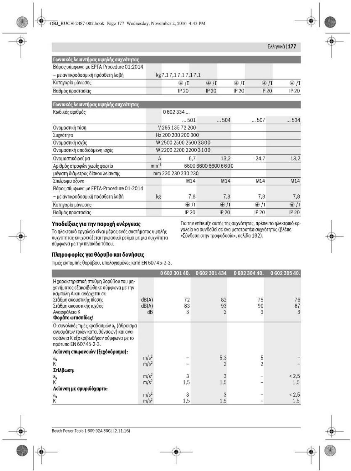
Notes on the Power Supply
The power tool is part of a high-frequency system and requires three-phase current with a frequency according to the type plate.
To reach this frequency, the power tool must be connected with a frequency converter (see "Connection to the Power Supply", page 33).
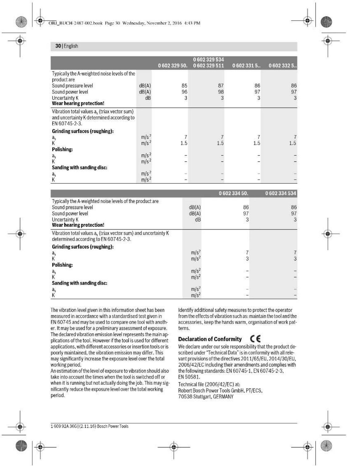
Noise/Vibration Information
Sound emission values determined according to EN 60745-2-3.
| 0 602 301 40. | 0 602 301 434 | 0 602 304 40. | 0 602 305 40. | |
| Typically the A-weighted noise levels of the product are | ||||
| Sound pressure level | dB(A) | 72 | 82 | 79 |
| Sound power level | dB(A) | 83 | 93 | 90 |
| Uncertainty K | dB | 3 | 3 | 3 |
| Wear hearing protection! | ||||
| Vibration total values \( a_{\mathrm {n}} \)(triax vector sum) and uncertainty K determined according to EN 60745-2-3. | ||||
| Grinding surfaces (roughing): | ||||
| \( a_{\mathrm {n}} \) | m/s2 | - | 5.3 | 5 |
| K | m/s2 | - | 2 | 2 |
| Polishing: | ||||
| \( a_{\mathrm {n}} \) | m/s2 | 3 | 3 | - |
| K | m/s2 | 1.5 | 1.5 | - |
| Sanding with sanding disc: | ||||
| \( a_{\mathrm {n}} \) | m/s2 | 3 | 3 | - |
| K | m/s2 | 1.5 | 1.5 | - |
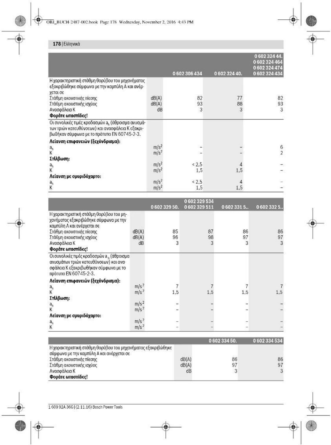
| 0 602 306 434 | 0 602 324 40. | 0 602 324 44,0 602 324 4640 602 324 4740 602 324 434 | |
| Typically the A-weighted noise levels of the product are | |||
| Sound pressure level dB(A) | 82 | 77 | 82 |
| Sound power level dB(A) | 93 | 88 | 93 |
| Uncertainty K dB | 3 | 3 | 3 |
| Wear hearing protection! | |||
| Vibration total values \( a_h \) (triax vector sum) and un- certainty K determined according to EN 60745-2-3. | |||
| Grinding surfaces (roughing): | |||
| \( a_h \)m/s2 | - | - | 6 |
| Km/s2 | - | - | 2 |
| Polishing: | |||
| \( a_h \)m/s2 | < 2.5 | 4 | - |
| Km/s2 | 1.5 | 1.5 | - |
| Sanding with sanding disc: | |||
| \( a_h \)m/s2 | < 2.5 | 4 | - |
| Km/s2 | 1.5 | 1.5 | - |
Bosch Power Tools 1609 92A 36C (2.11.16)


OBI_BUCH-2487-002.book Page 31 Wednesday, November 2, 2016 4:43 PM
English 31
Henk Becker
Executive Vice President Engineering
Helmut Heinzelmann
Head of Product Certification PT/ECS

Robert Bosch Power Tools GmbH
70538 Stuttgart,GERMANY
Stuttgart, 01.01.2017
Assembly
Mounting the Protective Devices
General Information
- Disconnect the power supply before making any adjustments, changing accessories, or placing the machine aside. This safety measure prevents accidental starting of the power tool.
Note: After breakage of the grinding disc during operation or damage to the holding fixtures on the protection guard/power tool, the machine must promptly be sent to an after-sales service agent for maintenance. For addresses, see section "After-sales Service and Application Service".
Adjust protection guards in such a manner that sparking toward the operator is prevented.
Note: The encoding keys of the protection guards ensure that only a protection guard that fits the machine type can be mounted.
Protection Guard for Grinding (see figure A)
Applies for the following types:
-060230440. -06023295..
-0602324434 -06023315..
-0.60232444 -0.6023325
-0.602324464 -0.6023345
-0602324474
- Place the protection guard 6 with the encoding key 8 engaging into the groove on the spindle collar 4 until the shoulder of the protection guard is seated against the flange of the power tool.
- Adapt the position of the protection guard to the requirements of the work step.
- Secure the protection guard by tightening locking screw 7 with a tightening torque of at least 10Nm .
Protection Guard for Cutting
Applies for the following types:
-060230440. -06023295..
-0602324434 -06023315..
-060232444. -06023325..
-0602324464 -06023345..
-0602324474
For cutting with bonded abrasives, always use a protection guard for cutting.
For cutting stone, always use a cutting guide with dust extraction protection guard (accessory).
The protection guards for cutting are mounted analogue to the standard protection guards (see figure A).
Vibration-dampening
Auxiliary Handle
(see figure B)
The vibration-dampening auxiliary handle reduces the vibrations, making operation more comfortable and secure.
Operate your machine only with the auxiliary handle 2.
- Screw the auxiliary handle 2 on the right or left of the machine head depending on the working method.
Do not make any alterations to the auxiliary handle.
Do not continue to use an auxiliary handle if it is damaged.
Hand Guard (see figure C)
Applies for the following types:
-06023014.. -060232440.
-060230540.
-0602306434
For operations with the rubber sanding plate 17 or with the cup brush/wheel brush/flap disc, always mount the hand guard 9.
The hand guard 9 is fastened with the auxiliary handle 2.
Mounting the Grinding Tools
General Information
Disconnect the power supply before making any adjustments, changing accessories, or placing the machine aside. This safety measure prevents accidental starting of the power tool.
Pay attention to the dimensions of the grinding tools. The mounting hole diameter must fit the mounting flange without play. Do not use reducers or adapters.
Clean the grinder spindle 3 and all parts to be mounted.
After mounting the grinding tool and before switching on, check that the grinding tool is correctly mounted and that it can turn freely. Make sure that the grinding tool does not graze against the protection guard or other parts.
Mounting Grinding or Cutting Discs (see figures D1-D2)
Applies for the following types:
-060230440. -06023315..
-060232444,..464 -06023325.
474.434 -06023345
-06023295..
Installation
- Make sure that the fitting protection guard is mounted (see "Mounting the Protective Devices", page 31).
- Place the clamping flange 10 on the grinder spindle 3. A plastic part (O ring) is fitted around the centring collar of mounting flange 10. If the O-ring is missing or damaged, it must immediately be replaced before mounting flange 10 is mounted.
- Mount the desired grinding/cutting disc 11 in the correct rotation direction onto the grinder spindle 3.
Bosch Power Tools 1609 92A 36C (2.11.16)


OBI_BUCH-2487-002.book Page 32 Wednesday, November 2, 2016 4:43 PM
32|English
- Place the clamping nut 12 onto the spindle thread so that the central recess of the clamping nut faces upward.
Tighten the clamping nut with two-pin spanner 13, while counter-holding the spanner surfaces of the grinder spindle 3 with open-end spanner 14.
Removal
Hold the grinder spindle 3 on the spanner surfaces with open-end spanner 14.
- Unscrew the clamping nut 12 from the grinder spindle with two-pin spanner 13, while counter-holding the spanner surfaces with open-end spanner 14.
- Afterwards, pull the grinding tool and the mounting flange from the grinder spindle.
Machines with Spindle Lock Button 5
Applies for the following types:
-060232440.
-0602324434
-060232444.
For machines with spindle lock button 5, counter-holding with an open-end spanner is not required when mounting grinding tools (see figures E1-E2).
- Actuate the spindle lock button only when the grinder spindle is at a standstill. Otherwise, the machine may become damaged.
- Before installing or removing the grinding tool, press and hold spindle lock button 5 to lock the grinder spindle 3 in place.
- Mount the desired grinding tool (see "Mounting Grinding or Cutting Discs", page 31).
- Let go of the spindle lock button 5 to release the locked grinder spindle.
Mounting the Rubber Sanding Plate (see figure F)
Applies for the following types:
-06023014. -060232440
-060230540.
-0602306434
Installation
- Make sure that the hand guard and the auxiliary handle are mounted (see "Mounting the Protective Devices", page 31).
- Place the rubber sanding plate 17 onto the grinder spindle 3.
-Lay the sanding disc 16 on the rubber sanding plate. - Place the round nut 15 on the spindle collar.
- Tighten the round nut with two pin spanner 13, while counter-holding the spanner surfaces of the grinder spindle 3 with open-end spanner 14.
Take care that the round nut 15 is screwed completely into the bulge of the rubber sanding plate so that it does not interfere while sanding and the sanding disc is firmly seated.
Removal
Hold the grinder spindle 3 on the spanner surfaces with open-end spanner 14.
- Unscrew the round nut 15 from the grinder spindle with two-pin spanner 13, while counter-holding the spanner surfaces with open-end spanner 14.
- Pull the sanding disc and the rubber sanding plate from the grinder spindle.
Mounting the Buffing Disc (see figure G)
Applies for the following types:
Pay attention that the thread of the buffing disc fits exactly on the grinder spindle thread (M14).
Make sure that the hand guard and the auxiliary handle are mounted (see "Mounting the Protective Devices", page 31).
- Screw the buffing disc 18 so far onto the grinder spindle 3 that it rests firmly against the face surface of the grinder spindle, while counter-holding the spanner surfaces of the grinder spindle 3 with open-end spanner 14.
Removal
Unscrew the tightly seated buffing disc 18 from the grinder spindle by applying an open-end spanner to the buffing disc spanner surfaces, while counter-holding the spanner surfaces of the grinder spindle 3 with open-end spanner 14.
Mounting Wire Brushes (see figure H)
Applies for the following types:
-060230440. -06023315..
-060232444,..464, -06023325.
474.434 -06023345..
-06023295..
Installation
Pay attention that the thread of the wire brush fits exactly on the grinder spindle thread (M14).
Make sure that the hand guard and the auxiliary handle are mounted (see "Mounting the Protective Devices", page 31).
Screw the desired wire brush 19 (cup brush or wire wheel) so far onto the grinder spindle 3 that it rests firmly against the face surface of the grinder spindle, while counter-holding the spanner surfaces of the grinder spindle with open-end spanner 14.
Removal
- Unscrew the tightly seated wire brush 19 from the grinder spindle by applying an open-end spanner to wire brush spanner surfaces, while counter-holding the spanner surfaces of the grinder spindle 3 with open-end spanner 14.
Dust/Chip Extraction
Dusts from materials such as lead-containing coatings, some wood types, minerals and metal can be harmful to one's health. Touching or breathing-in the dusts can cause allergic reactions and/or lead to respiratory infections of the user or bystanders.
1609 92A 36G| (2.11.16) Bosch Power Tools


English | 33
Certain dusts, such as oak or beech dust, are considered as carcinogenic, especially in connection with wood-treatment additives (chromate, wood preservative). Materials containing asbestos may only be worked by specialists.
- As far as possible, use a dust extraction system suitable for the material.
- Provide for good ventilation of the working place.
- It is recommended to wear a P2 filter-class respirator. Observe the relevant regulations in your country for the materials to be worked.
Prevent dust accumulation at the workplace. Dusts can easily ignite.
Connection to the Power Supply
For operation of the power tools, a frequency converter is required that generates three-phase current with a frequency according to that listed on the type plate.
Frequency converters are available in various sizes, with different frequencies, secondary voltages and rated outputs. The choice of the frequency converter depends on the power tools to be connected. When selecting a frequency converter, contact your Bosch-specialist shop for advice.
The machine is provided with a four meter long specialty cable without plug. To put it into operation, the specialty cable must be equipped with a four-pole CEE plug (identification colour green).
Additionally, the machine can be equipped with a commercially available motor protection switch for protection against overload. The adjustment range of the motor protection switch must cover the nominal current of the power tool (see "Technical Data"). The motor protection switch must react in less than one second.
Please observe the safety warnings and assembly instructions in the operating instructions of the motor protection switch!
Mounting the CEE Plug (see figures I1-I2)
- Loosen the two screws 22 and pull the plug insert 21 out of the plug housing of the CEE plug 24.
Cut off the plastic sleeve 25 according to the diameter of the specialty cable of the power tool and insert the specialty cable through the CEE plug housing. - Insert the four conductors through the cable strain relief 20.
- Loosen the four small screws 23 in the plug insert 21 and insert
the conductor ferrule of the brown L1 conductor into contact tube L1.
the conductor ferrule of the blue L2 conductor into contact tube L2;
the conductor ferrule of the black L.3 conductor into contact tube L3,
and the conductor ferrule of the green/yellow conductor into the earthing contact tube
- Firmly tighten the four small screws 23 in the plug insert 21 to affix the conductors.
-
Now, tighten the screws of the cable strain relief 20 so that the cable clamp goes around the complete cable sheath, ensuring that no pressure is on the conductor ferrules.
-
Reinsert plug insert 21 into the housing of the CEE plug 24 and tighten both screws 22 again.
- Afterwards, check the proper function of the protective conductor.
- Insert the CEE plug 24 of the power tool into the connection socket of the frequency converter.
Now, connect the frequency converter to the power supply. For information on how to connect the frequency converter to the power supply, see the frequency converter operating instructions.
Afterwards, check the rotation direction!
Checking the Rotation Direction
The rotation direction of the grinder spindle must correspond with the arrow on the power tool.
If the grinder spindle rotates in the wrong direction when putting into operation for the first time (see "Switching the Power Tool On/Off", page 34), switch the power tool off immediately and disconnect it from the power supply.
- Loosen the two screws 22 again and pull the plug insert 21 out of the plug housing of the CEE plug 24.
- Loosen the conductor ferrules of the black and brown conductors from their contact tubes.
- Now, insert the conductor ferrule of the black conductor L3 into contact tube L1, and the conductor ferrule of the brown conductor L1 into contact tube L3.
- Firmly tighten the small screws 23 in the plug insert 21 to affix the conductors.
- Reinsert plug insert 21 into the housing of the CEE plug 24 and tighten both screws 22 again.
- Afterwards, check the proper function of the protective conductor.
- Reconnect the power tool to the power supply.
Operation
Starting Operation
The voltage and frequency of the power source must correspond with the data on the type plate of the power tool.
- Check grinding tools before using. The grinding tool must be mounted properly and be able to move freely. Carry out a test run for at least one minute with no load. Do not use damaged, out-of-centre or vibrating grinding tools. Damaged grinding tools can burst and cause injuries.
If the machine should unexpectedly stop operating even though the On/Off switch 1 is in the "On" position, set the On/Off switch to "Off". This will prevent uncontrolled restarting of the machine. Before restarting the machine, check the power supply (see "Connection to the Power Supply", page 33).
Always connect the power tool to the frequency converter first, before connecting the frequency converter to the mains supply.
To save energy, only switch the power tool on when using it.


34 | English
Switching the Frequency Converter On/Off
The frequency converter must be put into operation first before actuating the power tool.
For this, observe the operating instructions of the frequency converter.
Switching the Power Tool On/Off with the On/Off Switch (see figure J1)
Applies for the following types:
-06023244.
- To start the machine, push the On/Off switch 1 forwards.
- To lock the On/Off switch 1, press the On/Off switch 1 down at the front until it latches.
- To switch off the power tool, release the On/Off switch 1. When the On/Off switch 1 is locked-on, briefly press it toward the rear and then release it.
Switching the Power Tool On/Off
with Safety Switch (see figure J2)
Applies for the following types:
-06023014.. -06023295..
-060230440. -06023315.
-060230540. -06023325..
-0602306434 -06023345..
To start the power tool, press the On/Off switch 1 forward and then down.
- To lock-on the pressed On/Off switch 1, push the On/Off switch 1 further forward.
- To switch off the power tool, release the On/Off switch 1, or when it is locked, briefly press the On/Off switch 1 and then release it.
Working Advice
- Disconnect the power supply before making any adjustments, changing accessories, or placing the machine aside. This safety measure prevents accidental starting of the power tool.
Exercise caution when cutting slots in structural walls; see Section "Information on Structures". - Clamp the workpiece if it does not remain stationary due to its own weight.
Do not strain the machine so heavily that it comes to a standstill.
After heavily straining the power tool, continue to run it at no-load for several minutes to cool down the accessory.
Sanding with the Flap Disc
With the flap disc (accessory), curved surfaces and profiles can be worked.
Flap discs have a considerably higher service life, lower noise levels and lower sanding temperatures than conventional sanding sheets.
Cutting Metal (see figure K)
For cutting with bonded abrasives, always use a protection guard for cutting.
When cutting, work with moderate feed, adapted to the material being cut. Do not exert pressure onto the cutting disc, tilt or oscillate the machine.
Do not reduce the speed of running down cutting discs by applying sideward pressure.
The machine must always work in an up-grinding motion. Otherwise, the danger exists of it being pushed uncontrolled out of the cut.
When cutting profiles and square bar, it is best to start at the smallest cross section.
Cutting Stone
- Provide for sufficient dust extraction when cutting stone.
Wear a dust respirator.
The machine may be used only for dry cutting/grinding.
For cutting stone, it is best to use a diamond cutting disc. For safety against jamming, a special cutting guide with dust extraction protection guard (accessory) must be used.
Operate the machine only with dust extraction and additionally wear a dust protection mask.
The vacuum cleaner must be approved for the extraction of masonry dust. Bosch provides suitable vacuum cleaners.
- Switch on the machine and place the front part of the cutting guide on the workpiece. Slide the machine with moderate feed, adapted to the material to be worked.
For cutting especially hard material, e. g., concrete with high pebble content, the diamond cutting disc can overheat and become damaged as a result. This is clearly indicated by circular sparking, rotating with the diamond cutting disc.
In this case, interrupt the cutting process and allow the diamond cutting disc to cool by running the machine for a short time at maximum speed with no load.
Noticeably decreasing work progress and circular sparking are indications of a diamond cutting disc that has become dull. Briefly cutting into abrasive material (e.g., lime-sand brick) can reshappen the disc again.
Information on Structures
Slots in structural walls are subject to the Standard DIN 1053 Part 1, or country-specific regulations.
These regulations are to be observed under all circumstances. Before beginning work, consult the responsible structural engineer, architect or the construction supervisor.
Rough Grinding
Never use a cutting disc for roughing.
The best roughing results are achieved when setting the machine at an angle of 30^ to 40^ . Move the machine back and forth with moderate pressure. In this manner, the workpiece will not become too hot, does not discolour and no grooves are formed.
Sanding with Sanding Discs and the Rubber Sanding Plate The choice of the suitable sanding paper depends on the material to be worked.
Bosch offers various sanding-paper qualities that fit the rubber sanding plate. Contact your specialist shop for advice.


OBI_BUCH-2487-002.book Page 35 Wednesday, November 2, 2016 4:43 PM
Polishing with the Buffing Disc
When polishing, a polishing agent is applied to the buffing disc or the material being polished, and worked into the surface of the material by means of rotation.
When working in several polishing steps, where each polishing agent has a finer grain, a separate buffing pad must be used for each grain size.
Thoroughly clean the surface of the material being worked between each polishing step.
Maintenance and Service
Maintenance and Cleaning
Disconnect the power supply before making any adjustments, changing accessories, or placing the machine aside. This safety measure prevents accidental starting of the power tool.
For safe and proper working, always keep the machine and ventilation slots clean.
In extreme conditions, always use dust extraction as far as possible. Blow out ventilation slots frequently and install a portable residual current device (PRCD). When working metals, conductive dust can settle in the interior of the power tool. The total insulation of the power tool can be impaired.
Regularly measure the no-load speed of the grinder spindle. When the measured value is more than 10% above or below the specified no-load speed (see "Technical Data"), have the machine checked by an authorised service agent for Bosch power tools. When the no-load speed is too high, the application tool can break; when the no-load speed is too low, the working performance is reduced.
Use only original cables! Before each use, check the power tool, cable and plug for possible damage. Cables and plugs may not be repaired, but must be exchanged in order to avoid danger.
Have maintenance and repair work performed only by qualified specialists. In this manner, it can be ensured that the safety of the power tool is maintained.
Clean the connection sockets, couplers and plugs of the tool, after it has been disconnected from the mains supply, using a dry, lint free cloth and remove dust and dirt particles.
Clean the gearbox after the first 150 running hours using a mild solvent. Follow the solvent manufacturers directions for use and disposal. Lubricate the gearbox using Bosch gearbox lube. Repeat the lubrication procedure every 300 hours after the initial gearbox service.
An authorized Bosch after-sales service agent will carry out this work quickly and reliably.
If the replacement of the supply cord is necessary, this has to be done by Bosch or an authorized Bosch service agent in order to avoid a safety hazard.
Please store and handle the accessory(-ies) carefully.
English | 35
Accessories
Information about the complete quality accessory program can be found on the Internet at www.bosch-pt.com and www.boschproductiontools.com or at your dealer.
After-sales Service and Application Service
Our after-sales service responds to your questions concerning maintenance and repair of your product as well as spare parts. Exploded views and information on spare parts can also be found under:
www.bosch-pt.com
Bosch's application service team will gladly answer questions concerning our products and their accessories.
In all correspondence and spare parts orders, please always include the 10-digit article number given on the nameplate of the product.
Great Britain
Robert Bosch Ltd. (B.S.C.)
P.O.Box 98
Broadwater Park
North Orbital Road
Denham
Uxbridge
UB95HJ
At www.bosch-pt.co.uk you can order spare parts or arrange the collection of a product in need of servicing or repair.
Tel. Service: (0344) 7360109
E-Mail: boschservicecentre@bosch.com
Ireland
Origo Ltd.
Unit 23 Magna Drive
Magna Business Park
City West
Dublin 24
Tel. Service: (01) 4666700
Fax: (01) 4666888
Australia, New Zealand and Pacific Islands
Robert Bosch Australia Pty. Ltd.
Power Tools
Locked Bag 66
Clayton South VIC 3169
Customer Contact Center
Inside Australia:
Phone: (01300) 307044
Fax: (01300) 307045
Inside New Zealand
Phone: (0800) 543353
Fax: (0800) 428570
Outside AU and NZ:
Phone: +61 395415555
www.bosch.com.au
Republic of South Africa
Customer service
Hotline: (011) 6519600


38 | Français
OBI_BUCH-2487-002.book Page:45 Wednesday, November 2, 2016 4:43 PM
Francais | 45
OBI_BUCH-2487-002.book Page:46 Wednesday, November 2, 2016 4:43 PM
46 | Français
Executive Vice President
Engineering
Helmut Heinzelmann
Head of Product Certification
PT/ECS

iV. h = m_c
Robert Bosch Power Tools GmbH
70538 Stuttgart,GERMANY
Stuttgart, 01.01.2017
Montage
Henk Becker Helmut Heinzelmann Executive Vice President Head of Product Cert Engineering PT/ECS

Robert Bosch Power Tools GmbH
70538 Stuttgart,GERMANY
Stuttgart, 01.01.2017
Montaje
OBI_BUCH-2487-002.book Page 62 Wednesday, November 2, 2016 4:43 PM
62 | Espanol
4hastra'spectarcelollarde lacapuera protectorca contra lbrida de la herramanta electrica.
OBI_BUCH-2487-002.book Page:65 Wednesday,November 2,2016 4:43PM
Espanol|65
-06023014.. -06023295..
-060230440. -06023315..
-0.60230540 -0.6023325
-0602306434 -06023345..
OBI_BUCH-2487-002.book Page 71 Wednesday, November 2, 2016 4:43 PM
Portugues 71
OBI_BUCH-2487-002.book Page 75 Wednesday, November 2, 2016 4:43 PM
Portugues 75
OBI_BUCH-2487-002.book Page 76 Wednesday, November 2, 2016 4:43 PM
76 | Português
Executive Vice President
Engineering
Helmut Heinzelmann
Head of Product Certification

Robert Bosch Power Tools GmbH
70538 Stuttgart,GERMANY
Stuttgart, 01.01.2017
Montagem
bracos reduz as vibra
OBI_BUCH-2487-002.book Page: 85 Wednesday, November 2, 2016 4:43 PM
Italiano|85
OBI_BUCH-2487-002.book Page 91 Wednesday, November 2, 2016 4:43 PM
Italiano|91
OBI_BUCH-2487-002.book Page 93 Wednesday, November 2, 2016 4:43 PM
Executive Vice President Engineering
Helmut Heinzelmann
Head of Product Certification PT/ECS

i.v. k = m _____
Robert Bosch Power Tools GmbH 70538 Stuttgart, GERMANY Stuttgart, 01.01.2017
Bosch Power Tools 1609 92A 36C (2.11.16)

OBI_BUCH-2487-002.book Page 94 Wednesday, November 2, 2016 4:43 PM
94 Italiano
Montaggio
OBI_BUCH-2487-002.book Page 107 Wednesday, November 2, 2016 4:43 PM
Nederlands | 107
OBI_BUCH-2487-002.book Page 109 Wednesday, November 2, 2016 4:43 PM
Nederlands|109
Henk Becker Helmut Heinzelmann Executive Vice President Head of Product Certification Engineering PT/ECS

Robert Bosch Power Tools GmbH 70538 Stuttgart,GERMANY Stuttgart,01.01.2017
Montage
OBI_BUCH-2487-002.book Page 110 Wednesday, November 2, 2016 4:43 PM
110|Nedenlnds
OBI_BUCH-2487-002.book Page 123 Wednesday, November 2, 2016 4:43 PM
Dansk|123
| 0 602 329 50. | 0 602 329 534 | 0 602 331 5.. | 0 602 332 5.. | ||
| 0 602 329 511 | |||||
| Samléde vibrationsværddier \( a_h \) (vektorsumfor tre retninger) og usikkerhed K beregnetiht. EN 60745-2-3. | |||||
| Overfladeslibning (skrubning): | |||||
| \( a_h \) | \( m/s^2 \) | 7 | 7 | 7 | 7 |
| K | \( m/s^2 \) | 1,5 | 1,5 | 1,5 | 1,5 |
| Polering: | |||||
| \( a_h \) | \( m/s^2 \) | - | - | - | - |
| K | \( m/s^2 \) | - | - | - | - |
| Slibning med silbeblad: | |||||
| \( a_h \) | \( m/s^2 \) | - | - | - | - |
| K | \( m/s^2 \) | - | - | - | - |
| 0 602 334 50. | 0 602 334 534 | |
| Værktajets A-vurdere lydtrykniveau er typisk | ||
| Lydtrykniveau | dB(A) | 86 |
| Lydeffektniveau | dB(A) | 97 |
| Usikkerhed K | dB | 3 |
| Brug horevaarn! | ||
| Samlke vibrationsværddier \( a_{i} \) (vektorsum for tre retninger) ogusikkerhed K beregnet iht. EN 60745-2-3. | ||
| Overfladeslibning (skrubning): | ||
| \( a_{i} \) | \( m/s^2 \) | 7 |
| K | \( m/s^2 \) | 3 |
| Polering: | ||
| \( a_{i} \) | \( m/s^2 \) | - |
| K | \( m/s^2 \) | - |
| Slibning med silbeblad: | ||
| \( a_{i} \) | \( m/s^2 \) | - |
| K | \( m/s^2 \) | - |
Det syingningsniveau, der er angivet i nervaerende instruk tioner, er blevet malt ith. en standardiseret malprocesi
Executive Vice President
Engineering
Helmut Heinzelmann
Head of Product Certification
PT/ECS

Robert Bosch Power Tools GmbH
70538 Stuttgart,GERMANY
Stuttgart, 01.01.2017
Montering
OBI_BUCH-2487-002.book Page 132 Wednesday, November 2, 2016 4:43 PM
132 | Svenska
-060232444,464.474.434
-06023295..
-06023315..
-06023325
-06023345..
OBI_BUCH-2487-002.book Page 135 Wednesday, November 2, 2016 4:43 PM
| Högtfrekvensvinkelslipar | ||||||
| Märkström A | 5 | 10 18 10 27 | ||||
| Tomgängsvartval | min1 | 6600 | 6600 | 6600 | 6600 | |
| max. slipskivsdiameter | mm 230 | 230 | 230 | 230 | ||
| Slipspindelgånga | M14 | M14 | M14 | M14 | ||
| Vikt enligt EPTA-Procedure 01:2014 - med vibrationsdämpande stöchhandtag | kg | 7,1 | 7,1 | 7,1 | 7,1 | 7,1 |
| Skyddsklass | ± /I | ± /I | ± /I | ± /I | ± /I | |
| Kapslingsklass | IP 20 | IP 20 | IP 20 | IP 20 | IP 20 | |
| Högfrektvensvinkelslipar | |||||
| Artikelnummer | 0 602 334 ... | ||||
| ... 501 | ... 504 | ... 507 | ... 534 | ||
| Märksprüning | V | 265 | 135 | 72 | 200 |
| Frekvens | Hz | 200 | 200 | 200 | 300 |
| Upptagen märkeffekt | W | 2500 | 2500 | 2500 | 3800 |
| Avgiven märkeffekt | W | 2200 | 2200 | 2200 | 3100 |
| Märkström | A | 6,7 | 13,2 | 24,7 | 13,2 |
| Tomgangsvarval | min1 | 6600 | 6600 | 6600 | 6600 |
| max. slipskivsdiameter | mm | 230 | 230 | 230 | 230 |
| Slippspindelgänga | M14 | M14 | M14 | M14 | |
| Vikt enligt EPTA-Procedure 01:2014 - med vibrationsdämpande stödhandtag | kg | 7,8 | 7,8 | 7,8 | 7,8 |
| Skyddsklass | #/1 | #/1 | #/1 | #/1 | |
| Kapslingsklass | IP 20 | IP 20 | IP 20 | IP 20 | |
OBI_BUCH-2487-002.book Page 137 Wednesday, November 2, 2016 4:43 PM


Henk Becker
Executive Vice President Engineering
Helmut Heinzelmann
Head of Product Certification
PT/ECS

Robert Bosch Power Tools GmbH
70538 Stuttgart, GERMANY
Stuttgart, 01.01.2017
Montage
OBI_BUCH-2487-002.book Page 138 Wednesday, November 2, 2016 4:43 PM
138 | Svenska
Vibrationsdampande stodhantag (sebildB)
OBI_BUCH-2487-002.book Page 140 Wednesday, November 2, 2016 4:43 PM
140 | Svenska
Bosch Service Center
Telegrafvej 3
2750 Ballerup
Danmark
Tel.: (08) 7501820 (inom Sverige)
Fax: (011) 187691
Avfallshantering
Gjelder for all type


OBI_BUCH-2487-002.book Page 149 Wednesday, November 2, 2016 4:43 PM
Norsk|149
OBI_BUCH-2487-002.book Page 155 Wednesday, November 2, 2016 4:43 PM
Suomi | 155
Rett tilendringer forbeholds.
Suomi
Turvallisuusohjeita
OBI_BUCH-2487-002.book Page 159 Wednesday, November 2, 2016 4:43 PM
Suomi | 159
OBI_BUCH-2487-002.book Page 163 Wednesday, November 2, 2016 4:43 PM
Suomi | 163
| 0602 301 40. | 0602 301 434 | 0602 304 40. | 0602 305 40. | |
| Värähtely nhteisarvot a, (kolmen suunnan vektorisumma) ja epävarnuus K mitattuna EN 60745-2-3 mukaan. | ||||
| Pintahionta (karhennus): | ||||
| a, | m/s2 | - | 5,3 | 5 |
| K | m/s2 | - | 2 | 2 |
| Kiillotus: | ||||
| a, | m/s2 | 3 | 3 | - |
| K | m/s2 | 1,5 | 1,5 | - |
| Honta hiomapaperilla: | ||||
| a, | m/s2 | 3 | 3 | - |
| K | m/s2 | 1,5 | 1,5 | - |
OBI_BUCH-2487-002.book Page 164 Wednesday, November 2, 2016 4:43 PM
164 | Suomi
Henk Becker
Executive Vice President Engineering
Helmut Heinzelmann
Head of Product Certification
PT/ECS

iV. k = m _____
Asennus
OBI_BUCH-2487-002.book Page 165 Wednesday, November 2, 2016 4:43 PM
Suomi | 165
-060230440. -06023295..
-0602324434 -06023315..
-060232444. -06023325..
-0602324464 -06023345..
-0602324474
Ailaparate AIECtic unololec aogaaelaac kai on oynleic, Aie
AeKc kara Tm npon Tnu uno5ieow oopaleac ka Tov 06n yuun npol e nuoka aouou nektonkla, npukayia h/ka aaboepocraaupaqoc.
ΦAùEÀ É àè TC Pòoàé monouNTKÉ UMOÉIéK KAI OBNYIeK Yα ΜΑθE AALTVKTJXIPON.
O opiooc HAEKTKIO Eoyaleo NOn npnoonotra otnpo otoiouke uOoIEE aovapepetae ae nAeKTKIO epyaiaou TPOPOBOOTAVI an To AEKTKIO bIKTUO (ue AeKTKIO KA KAOIC KAcN cOe AeKTKIO epyaiaou NTOPOBOOTAVI an OmaTAPla (gxp, nAeKTKIO kALoo).
AoepaIeia 0to XoO epyaolac
Aiaiieoe Tov toue nou eaebe Kaoapokai kai aoiapevo.Aatfa h okeireve,neipoxecepayolacmuopel va onyauov de anuyuata.
Mny epyeOe me to nckpok oepaale o npalaoonou unopkivovoc eknpnc, 0to onio urapoxuv eekptka Uya, aepia h okvec. Ta nckpikca oepaiae jnupoyuov anpvipiao o onioic mopei va avagke cci t kovn h acavthmuacic.
Orav xnpoonoeite Toaektoko epyoaeio kpatate pakipd anuto taiaod k daa Tuovnapeupokoeva atogja.2e nepimnoanaoocm npoooxc oac mopoie vo xaaote tov eayxou tou naxnuafuotoc.
Haektpikn aopaleua
To pucu npkpuo epaiaou penei va taoie ot npia. Dc eptnetae kavevav tro netaTporntpocu qm. Mn npnoepnoe npaaopauotka qae ouubuo meyueva npkpuo epyaela.Ajeto nolinaq cik kataknnncipie meuvovuov tv klvvo npktonAnGic.
Anopeuyere tvn enaon Tou oouatoc aacpeyiwuece Eupaeveic onw owvvc,Beepavuad oogata (kaoPpoe), koulvenc yueia. OraT ovuaqa civai yewevo aucaetov KIOVUOC nKTOPOAMNlEAC.
Mnykctete ta unxavnqata ot Bpoxn nyn uypoa. H dielobuon nepov o'eva nektpko epayiao auvaio tv Kivvvo naekptponlac.
Mx npopoieire to nkeptko kaiobio yia va meaepete hva ovaphtoe to nkeptko epayelo, yia va byaeite to pao cno npitp. Kpatate to nkeptko kaiobio paqni ao npeboaue ccpokpaic, Koeptec aekue kai/ an oovnnte eapntjata. Tuyoy yaaoupe va npenayevna keptko kaiobio auovvovr kivnu naekpnomngic.
O'Tav epyc0e eva nAekpok oepyaleo ro unatbpov na xynpoonoeic kaoaoukuvoc (unauvTecc) ou evai katalan kai yia xiong oto anatbpO.Hx npn KALawiv enmuikuvanc katalan avya uai aoiipoucx oopouc Eaattuovravivoo nAekponiAic.
Otav npn ton nkeptok opealeou o uoepi
pAov elv avanopeuktn, toe xynauonotne evan
npoteutkn diakomnt diappoc (diakomnt FI/RCD).
Hxyn evo npnoateuok biakomnt diappoc exaTiwue Tov kivluo naektonngic.
Aoapka npoow
Na elte navto npoektkoc/pnooeukn,va dlve Tpooox thnp eyaiaou nokvee ka va xepilcote to mnaivnae pneokpke. Mn xprpoanone eva nkekpko epayaleio tav elce Koupaievoc/Koupauevin h atav bpiaoke one nTnv enpeia vapkwtkov, oivonteuipatc h qappakw. Mia anyula ampoeeia kata to xepiapo Tou naekpikou epayaleiou npopel va onnyoei oe aobaoaicpuantmuoiuc.
Φopate evav katalnlo yia aq nopatoctutko eonlao kai navtote npoatautkua yuaA. Ora'ov opate evav katalnlo npoatautkio eonlao omoic maoka npo
Bosch Power Tools 1609 92A 36C (2.11.16)


170|EAAnuKa
Otaioac an oKoyn, aviioaobntuk aunodmuata oopaaleiac, nooataeueko kapovoc waadn5ec, avakaya je to ekaotate epayalekai m xphan Tou, Eaatwewet aokhovoc taupauiaiikow.
AnopoyeTe TIV abelntn EkkvNn. BeaowBeTe ot to NkEeKIO eApAeLo EeI aoeOeTl nov to auVbOeTe Me To NkEeKIO kBtUo Me IVu mpatiaKaoc KaPov To npalaBcTe HTo pTaOpepTe. OTV aetappeTe To nEeKIO eApAeLo EoxvTc o6aTuAo aocto diakdtnn To stav ouvdeTe To uXavnuJe TIV mnypeuacrav au To elvai koumOn tBcN ON, tore dnnuupytei Kivuvoc Taupanuoy.
Apaapei an ta nakpka epyaleia tuxov auvarpoynuynpeva epyaia pouunoc n Kciadi npo 0eote to naekpkoepaiaoeieauopvy. Evaepaia kciidi auvarpoanoyev o evneupnepoevo tuja evoc unxavmuacmopei va obnyae ie raumpuouc.
Mny unepeknate tov auroac.Φovrtcye yauyn anpaalr oan tou oaiatoc ac kai biattpe nvtro tywnoppionla oc. Etounpoe va ekyete kalutepo t npynvua ne pniinuoic anpoooskntuv npnoofoe.
Φopate kataaannc vcbuata. Mn opate papia poue n koogjura. Kpatre ta paala oac, ta poya oac ka tayva oac maikpi ano kvojeva ecapjura. Xaapanv cviuaia, koogjura n jaakpa aia mnpociv enaouovn ckiuoeve ecapjura.
O'Atav unapexi n duvatotn ta uvaopoloync diatae C ov avappoponc n oauovic okvnic, beaowoe t on autc eiv ouvvepevc me to xuaivna paokcaon Xpouoioouvtai oovt. Hxprion iiae avappopcnic okovic npoeip va eartooei tv kivvvo nu npokaiein an in oikovj.
EmpeAeXeipopoc kai xpion nAektpikov epyaleow
Mny unepoopotve To npxavnna. Xnpoonoeite y Taey kntote epyola To nkeptko epyaIe no Nno ppoipctaiy turhy. Me To katalnn ao nkeptko epya Ie cyapcae KaAepaIepe Otnv avapepepv neipoxhayloc
Mn xpoaonouoane nore eva junxavnnaou exe xala- oqevdoikomtn. Evo naekpiko evayaleo nuov devuopeite nleov va to Boeote ae Aetoupyia kai/ hctoc Aeotoupyiac elv an Ckiivduvo ka npieira va eniokueaoted.
ByAte to pio an ty npia kai npapatey tv matapla npiv dieyavet oto nnuvma opnabotne copya opuongnpov aalecve eva cepnna hov npokatvaia dauoalae /vo amoynkocoe to npua. Autopnoaikpetae papaaoaieae, meuvowourov tov kivuvo an touyov ovbei knckivon tounaktpkoucpaiaei.
AduayyTe TaAekTkoepyaiaouSeXnpoaotie paia aniaia. Mny emptpe T xphon Tou naxanpatoc o atrao np deevai eokoeiueva u auto h evov dbaoeic npaooe ofnyic.Ta MeKtki epyaia eviat enkivbova otav xpnoaioouvtai ane ame npoana.
Naepinoisele NaooekrKa to kEeKpkiO epyAela. Ehxyctc,av t Kvooupeva eApntjmu Aetloupoovd apoyo, xocu Cp mAoakopov, nmuoc exovn aoei
Φaepel tuxv ecapntmuata tonola empeadouv totpo Naetoupyiaocuonkepkoepyaleiou. Aotre aTa taalaoue eacipnmaivuaemoeun npv ta cavaxpnounoue. H kach auvtanuvknpov evpaaclv anoteleiaat mawv atnuqnatu.
Aatnpelre Ta evyaleia konk Koepa kai KaBap. Ipoektikouvntprpeva Kcimck Epyaleia opnyuvovuuvuukokotka kai obnyoivutcu kucokotpa.
Xpnoaonoeir Taekrpkc oyaiae, Eapnna, napeKoepva cyaiaea Kt. ouuovpe tnc npolooc onyieAauBaeve eniic unouqacctokote ovwnkce kai tvu mbkteae onyoe. Hxnpomolonon Tnv ncktoikow cyaaeiuy ia cypoieec noevd npaoEIOVra wautu mopeiv va oyuiuynoe einkluvuec kataotaeOEi.
Service
AotnIeKpOepyaleoaoyienkeun ao apr Oekieuepevo npooamko kae yvnoa vataaakntka. Eta eopakite n t diatponn m aapaleiac tou nXavmuoc.
YnoBefiea aopaaelac yua ywviakouc aeavipces
Kovc unoeEeic aopaleac yia aeavon pe yuaoxapro Kaii
Iayei yia touc eHtumouc:
OBI_BUCH-2487-002.book Page 174 Wednesday, November 2, 2016 4:43 PM
174|EAAnvKa
Iepiypaipn Tou npoiovtroc kal nct loxuoC Tou

AiaBdote bace Tc umoBeIeic aopaaelac kai Tc onbnyie, Aueaeie, kata my thponyun ToU oBceew aoepaalek kai Toynbnyu npoei va npokaouov nKekpronlgy, npKayai /kai oBapoucTpaupamauoc.
Iapakaloupe avolte tn dumuovn eolba me tvneukovian tnc ouokucu Ka ophiote tvavogtn oo ba diajbcetnc obnyie xcpiauj.
XpnoofoovaeTOVnpoopto
Iayei yia touc Eeh tumouc
-06023014
-0.60230540
-0.602306434
-0.60232440
To nAekpkiO epyakio npooipctai yia laovi an yua doxapto KAI OIAOWIetaAIAIW KAI BepVIKWevov cHApceivw xupc Tn xhpi neveo.
Iayei yia tou eHc tumouc
-0.60230440
-060232444,...464,...474,...434
-06023295.
-06023315
-06023325
-06023345.
TnAekpkiOeayale npooipctai yia konH, Eoxovpioua kai Bouptiouma petaakaw kai pntivw uakuv xupic Tx npoh ne poiu.
Tia TnKoJe mepeva uAikLeavanpneiVAx npaonionol 0el evac eiokopnpuaactipac.
IaTnKOM TneopWJauW PmeIva oPovIoAeTe yia ma erapkH avapopOnnTnC oKoNc.
Ioxuia 0ouc tounous
Enptepetra va xpaonnoiouov anokkeiaikoi ou mnpaide6oevoei o iyekkpuevov ia ypone me auto to nekpipk epyale loqopuklmpc kai naiaodaiapyfnc.
Aneikovicioueva otoxieia
H anaplunanw amekovoeuv otoeyaw aapepat 1nmyamekovion Tou nkeptikou epyaleiou ot aeAla yapaikov.
1AakotIncON/OFF
2PooeemAaBn
3Aovor
4Aaipoc dOova
5PiKpOaVbAOWcEova
6Pooqukntipac
7 Bla6 oTepeoong ia npopuλaKTHpa
8Kwokonoinpevoekkvto
9Ppuaaknpaecipai
10ΦλavntzunodoxhμεδakruiioO
11AioKoc kaiavang / konh / ekovopapatoc
12NaIgduo
13TayocAic
14FepavikKaei6ipeovypa 17mm
15 TpoWuAoEa
16ΦAaλeaygnc
17 EAaOIOKc bIOKc AEiavoNG
18diokocoiAwoonC
19∑μρατόβομτα
20 Avakoupiqan katanovnnc (pc CFE)
21Eepnua pic (pCCEE)
22 Bièç (φις CEE)
23 Biéç στο εξαρημα φις 21 (Φις CEE)
24ΦCEB
25 Paaonik npoopa (pCCEE)
E'epoJtau no anekovovn npnyopovotv be nepeoxov t ot ntravopoukaia. Fu na npk katao oepaTaw Ko ita to npoyapua eepatntuv.
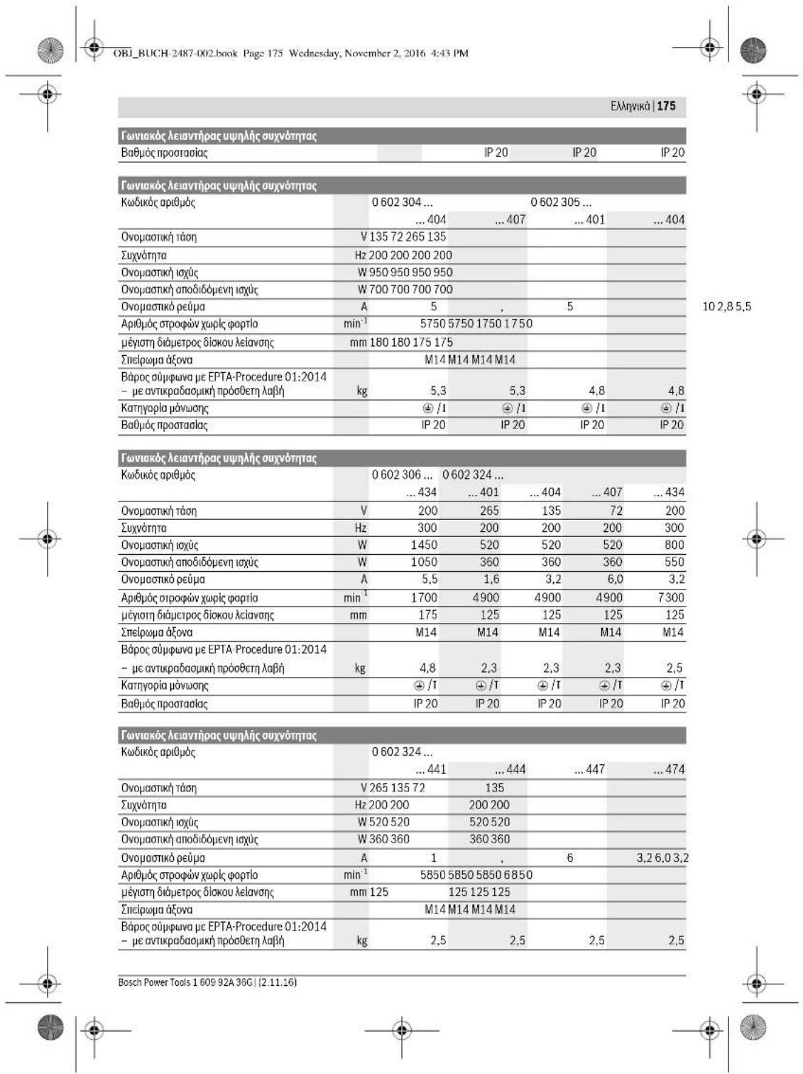
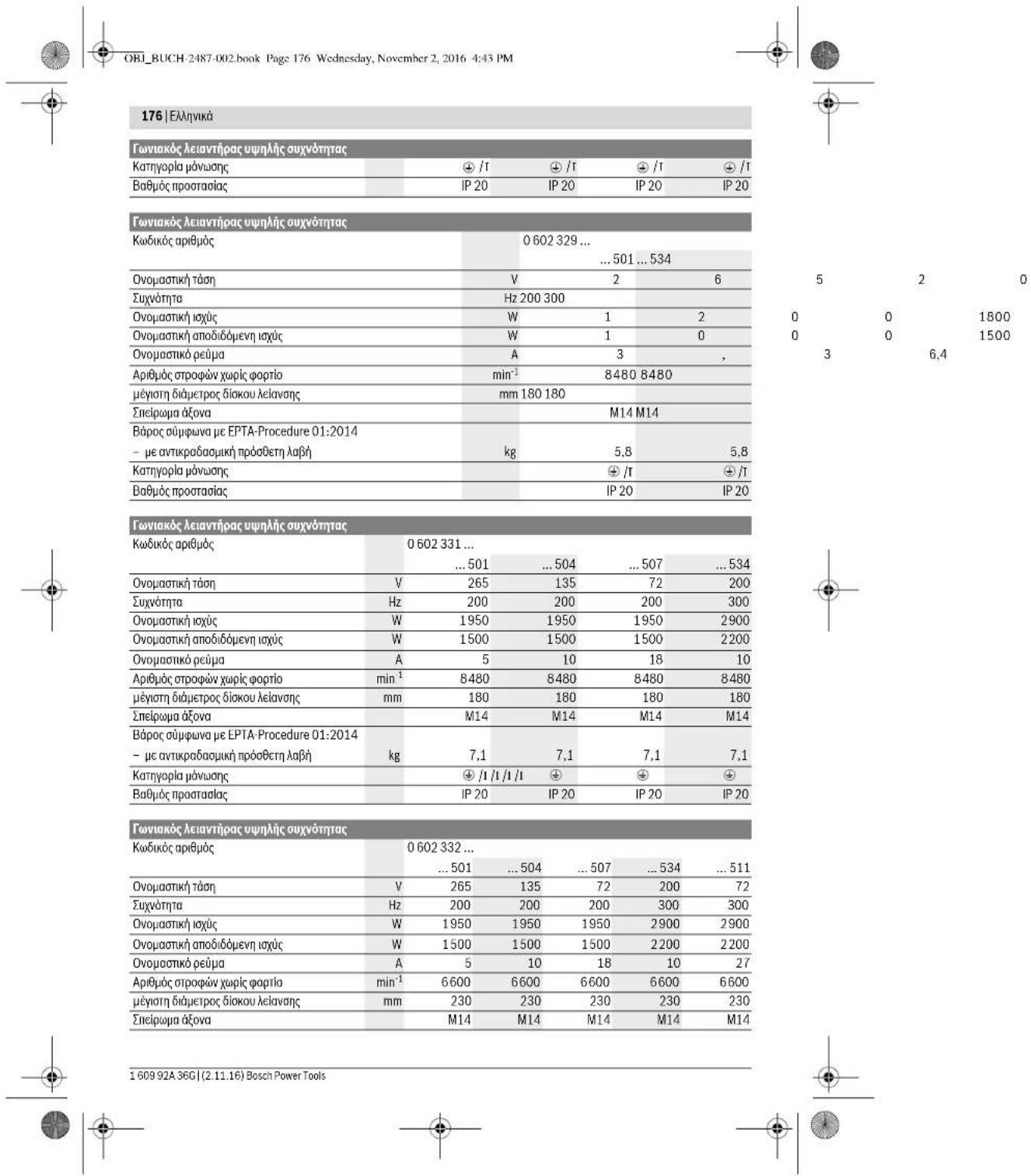
Texvika xapaktnpota
| Favivakóleiavtipac uunlncauvovmtac | ||||
| Kwδkóc apβμóc 0 602 301 ... | ...401 | ...404 | ...434 | |
| Övopaatikj táðn | V | 2 | 6 | 5 |
| Σuþvortna | Hz 200 200 300 | |||
| Övopaatikj iαúç | W | 6 | 0 | 0 |
| Övopaatikj anobidóevn iαúç | W | 4 | 4 | 0 |
| Övopaatikj oëupa | A | 1 | , | 6 |
| Apβμóc σροφών χωρίσ φοθίσ | min¹ | 4100 | 4100 | 6150 |
| μεγοιη διαμετρος διοκου λελαναίς | mm 125 125 125 | |||
| Σnelipoua áóva | M14 | M14 | M14 | |
| Bápoc ouμφωνa μe EPTA-Procedure 01:2014 | ||||
| - μe avικρaδaʊμkni προθεctη λαβή | kg 3,2 3,2 3,2 | |||
| Katzyopia pòvuaŋç | ± /I | ± /I | ± /I | |
1609 92A 36G| (2.11.16) Bosch Power Tools


135200
600900
440630
3,33,3
OBI_BUCH-2487-002.book Page 179 Wednesday, November 2, 2016 4:43 PM


| 0602 334 50. | 0602 334 534 | |
| Ötouyolçük tüpec kpaşağmá yı.(şθροιασa ayuç%päävtrpvkatacuk-θυσεων) kai avaaφλεία K εξακρβωθηκαν σύμανων με to npótnoEN 60745-2-3. | ||
| Aεiavan emφavειω (ξεχόνδριαμα): | ||
| an | m/s2 | 7 |
| K | m/s2 | 3 |
| Σιλβωση: | ||
| an | m/s2 | - |
| K | m/s2 | - |
| Aεiavan μe σρριδόχαρτο: | ||
| an | m/s2 | - |
| K | m/s2 | - |
H 3aBn kpaabawou nau apepetra oautc Tc onyie cexi peptb ouipwya me paia biadikaoka ptepnoc tnunonuev ano npto EN 607 45 ka npoe va xpyaoanoien yta nnuykpiian diaapbwnyektpknov eoyakeow. Elva enionk katann lan yia evn npaaovnu oioanyoiou nnc emapuvont anou tuc kpaadoaouic.
H oraun kpaabawou avapepetai ovtnpooanei tic baie Kxoheiou Tn naektpoi Epyaeio. Te neoithua oou, nou to naektpoi epyaleio xonpaoumoei yia aalec eepaoye, me diaopopetikid anakklovivna Eaepitraata huxipice cnapri ouvtrpon, toe n otanun kpaabawu npopi v anoklvica kaut autu, Autu npoei va ufoehce onjavktiTv eniBapuyon anotou kpaabaaoc kataTn auovlaki diapkeiaoloknpoou Tou xpvkoiv daatmuatoc nou epoxyeco
TAtnA KApBnKrKnJnTc nIeBapuovnc amTOUC kpaabauoc
Ta npTeiVa aaujavovnt eniOn cunbKa iOxpvoi KaTn T
diadkeao Tu oiovai To evayaleo Bpokaietkctc Aeitoupylaic
LeiToupeY, xwcip OwC OTN pnyaTuKotmTa va xnpauonoei
TAu AuOpNCi vceuocn eUyavtnkT Nv emBapuovn an
touk kpaabauoc kata T dIadkeao OlakAnpou Tou Xpvikou
diagTnATOCIO EvDAcOe.
I' auto, nov apxoei n dpaoan Twn kpaadawu npeneia va kaaboie taeumnpwpatuk petpa aopaaeioac vna Tpu oopataou tou xeiapit anow. Suvtnponon Tou nkyktpko evyaileou kai Tou eapitau wou npnayoonieoe, diarhnon cetov Tou xepoiu, opyvauaon Tnc ekteanev Tou dabiapowevyaiov
△nawon oupbaotntac C
Anovoume je anokkeiaikn aec eouwn, oTo npovou nou nepaepaaota TExkvaXapoknpiKtaiavntoayoe ae cckyotekdeqteauoyiv2011/65/EE,2014/30/EE, 2006/42/EK ouimpekaiaovevuvuamayuvounc kai tounciela me ta anokouba nprotuna: EN 60745-1, EN 60745-2-3. EN 50581.
Texvikoc paekaooc (2006/42/EK) ano:
Robert Bosch Power Tools GmbH, PT/ECS, 70538 Stuttgart, GERMANY
Henk Becker Helmut Heinzelmann Executive Vice President Head of Product Certification Engineering PT/ECS

Robert Bosch Power Tools GmbH 70538 Stuttgart,GERMANY Stuttgart,01.01.2017
SigmaoJyOn
EuvaopAoynon Tov npoateutukw biataeew
Revic unobieic
Na anouuvdeTe Tn ouakeun ao Tny tropoodota niv bdeEpyete Kmaia 0puon, npnv ano3eTe To Nktpko cypAio notav npokraa va aaAeTe Kanooe Eaptnu. AuTo npopuaKtiko MteTo eJnoiOle Tny kato Aoboc ekkvionTou nAekpkrO cyapeaiou.
Ynei:Ee neipinwnnou kata ndiapkeia nTg epyaoc
onao o diokoc acicvanc no anouotuv BmBoi ot iataneic uno
doxohrto npovpukmaikpa/ota nKepkpo epyaole,TOte TO
nKekkoepo epyaalelo pmei va npokkojuatel/ano tarela aleo
OTo Service. Tia ta atekien dieuovoeic bIe To Kepaalio
"Service ka npoxy oujoukow xphonca.
Na puHlEte Tou npauAukTpec KATe TEOIO ToPO,
Ote o OvNpApoc v nuV kateuovte noc toxip
Yn Taekvnta Kukidokoianyoc stou pnoiaakntpec eaoafoauov, ani mopoie vaovapaooygel ovoac katoL hao Lc y to ekatotare nAeKtropio evaepia nooepiaikpact.
Iipopukaktpa yia aeavon (beta ekova A) Ioybei yia touc Eehc tumouc:
-060230440. -06023295..
-0602324434 -06023315..
-060232444. -06023325..
-0602324464 -06023345..
-0602324474
TOnoBteIOTOVnpOuaKTHpa6TeToekKeVTOkwDkoIonI 10NC80nAoAoiKwDkoIoinC,0aJouTOaOVA4
Bosch Power Tools 1609 92A 36C (2.11.16)


OBI_BUCH-2487-002.book Page 180 Wednesday, November 2, 2016 4:43 PM
180|EAAnuKa
mexviXaKIOcIe nepAuaIOu npOoaknpa naovnФaVAtvU NaekpIKou OyaekIo.
Iayuiyia toucEeh tumouc:
Iayet yia tou c efnc rounoc:
-06023014.. -060232440.
-060230540.
-0602306434
TonoBttn
-BeBaiuOHeTe,OnEeiauauapAoynoyEoIpoopuaKaTnpacXepWknnpOaeTeanJbH (BJIeEeZUauapAoynoyTuV npoTatcucukv bIdKevn, oAcb 179).
TonoBTeTToAaOnxEvIOdiKocIeAoVcNc17nvoOToV oEoAoAciVoNc3.
Tonoernte to qukla aeIavoc 16 nwa sto aanrgevio biko aeIavoc.
Tono3rnto roptyyufoaia 15 roonepua tou e6va.
Biswate kaka to atpoyuAo naEabi me yavntokkeio 13, vovrpoxa Kovipadce me cy eupvkiKae 14 otny empeva eapoyouTou kaeiouoTou aOVA leavan3. Pooocic, va biobc to atpoyuAo naEabi 15 cvtAc oca any cooxn Tou aonvov biaoukai Aviaov, ia va mnu cunoikei neov kata n keivan ka iv npaaepocetra atebpato faoAo iacovan.
Anopukvov
-KaonrtoeOraepoTovOeAlovac3oNmEopvAdva eaoooyuToKaeiokUeVoeuvkoKaei614
-3eBbOaTeTo aOpyuUoNabUd15 Me To yauVcKcOio 13
am oTo aOva Iaeovc, evu tauroxpoVa Kovpapete Me to
yeavpuKo Kaeoi 14Ony emiOeviae apouyoNt ouTkeoiu.
- AepaipéTRE To φολα ΛελινόN, KAI To Maθηγένο Φιδα ΛελινόN and Tov d'ανα ΛελινόN.
Suvapoloyan tou slakou otiaawon (Bnae ekoVaG)
IoyuTuia Touc Eehr tonouc:
OBI_BUCH-2487-002.book Page 192 Wednesday, November 2, 2016 4:43 PM
192|Türkce
| Yüksek frekansl taşlama makinesi | |||||
| Ürün kodu | 0 602 334 ... | ||||
| ... 501 | ... 504 | ... 507 | ... 534 | ||
| Anma gerilimi | V 265 135 72 200 | ||||
| Frekans | Hz 200 200 200 300 | ||||
| Girgis güçü | W 2500 2500 2500 3800 | ||||
| Çişkes güçü | W 2200 2200 2200 3100 | ||||
| Anma akimi | A 6 | . | 7 | 13,2 24,7 13,2 | |
| Bostaki devirsaysı | dev/dak 6600 6600 6600 6600 | ||||
| Maks. taşlama disikiçapi | mm 230 230 230 230 | ||||
| Taşlama mili disi | M14 M14 M14 M14 | ||||
| Ağırkı EPTA-Procedure 01:2014'e gère - Titresjm onleyici ek tutamakla | kg 7,8 | 7,8 | 7,8 | 7,8 | |
| Korum sinifi | ®/I | ®/I | ®/I | ®/I | |
| Korum Türü | IP 20 | IP 20 | IP 20 | IP 20 | |
Enerji beslemesine iliskin aciklamalar
Elektriki el aleti yuksek frekansystemin bir parcasidir ve tip etiketinde belirtlen frekansa sahip 3 fazl alternatif akim gerektirir.
Bu krekansa ulasabilmek ici elektrikli el aletinin bir krekans donusturuciyede bagl olmasi gerekit (bakiniz: "Enerjiikmaline baiganti", saya 196).
OBI_BUCH-2487-002.book Page 193 Wednesday, November 2, 2016 4:43 PM
Turkce 193
| 0 602 306 434 | 0 602 324 40. | 0 602 324 44. | |
| 0 602 324 464 | |||
| 0 602 324 474 | |||
| 0 602 324 434 | |||
| Toplam titreşimiGeorge terleri a, (ucçystemsvektör topla-mentation) ve tolerans K, EN 60745-2-3 uyarıncı. | |||
| Yüseyi taşlama(kazima): | |||
| a1 | m/s2 | - | - |
| K | m/s2 | - | - |
| Polisaj: | |||
| a1 | m/s2 | < 2,5 | 4 |
| K | m/s2 | 1,5 | 1,5 |
| Zimpara kagida ilezimpara: | |||
| a1 | m/s2 | < 2,5 | 4 |
| K | m/s2 | 1,5 | 1,5 |
OBI_BUCH-2487-002.book Page 194 Wednesday, November 2, 2016 4:43 PM
194|Türke
Belirtilien titresim seviyesi elektrikli el alotinin temel kullanim alanarini tensiler edn. Acakelektrifik el ati baska kullanim alanarinda, farki aksesuarla, farki uzclarla kullanlirken veya yeterisz bakluma kullanlirken, titresim seviyesi belirtilien degerden farkli obalibur. Da bu toplam calisma suresi icindeki titresim yukunin onemil ojcle arturilir.
Titresimi yukun lam okaytahmin ede bilmek icin aletin kapa- li oldugu vya calstigi halde kullanladigui surei der dikkate alnmaldir. Bu, toplam calisma suresi icindeki titresimi yukun Snemli ocidce azaltablir.
Titresimin kullanciya bindirigi yuk icin onceden ek guyenik onlemleri alini. Ornegin: Elektriki elaetinin ve oclarin bakimi, ellerin sicak tutulmasi, is asamalarinin organize edilmisi.
Uygunluk beyani
C
Henk Becker Helmut Heinzelmann Executive Vice President Head of Product Certification Engineering PT/ECS

iV. k = m _____
Robert Bosch Power Tools GmbH
70538 Stuttgart, GERMANY
Stuttgart, 01.01.2017
Montaj

JCH-2487-002.book Page 200 Wednesday, November 2, 2016 4:43 PM


Polski 201
Serwis
OBI_BUCH-2487-002.book Page 203 Wednesday, November 2, 2016 4:43 PM
Polski 203
OBI_BUCH-2487-002.book Page 204 Wednesday, November 2, 2016 4:43 PM
204| Polski
OBI_BUCH-2487-002.book Page 207 Wednesday, November 2, 2016 4:43 PM
Polski 207
OBI_BUCH-2487-002.book Page 209 Wednesday, November 2, 2016 4:43 PM
Executive Vice President Engineering
Helmut Heinzelmann
Head of Product Certification PT/ECS

iV. k = m
Robert Bosch Power Tools GmbH
70538 Stuttgart, GERMANY
Stuttgart, 01.01.2017
Bosch Power Tools 1609 92A 36C (2.11.16)


Polski 211
Robert Bosch Sp. zo.o.
OBI_BUCH-2487-002.book Page 219 Wednesday, November 2, 2016 4:43 PM
Cesky|219
trickym proudem, nebezpeci pozaru nebo vaznym zranenl.
OBI_BUCH-2487-002.book Page 223 Wednesday, November 2, 2016 4:43 PM
Cesky|223
OBI_BUCH-2487-002.book Page 224 Wednesday, November 2, 2016 4:43 PM
224|Cesky
Henk Becker Helmut Heinzelmann Executive Vice President Head of Product Certification Engineering PT/ECS

iV. k = m _____
Robert Bosch Power Tools GmbH
70538 Stuttgart, GERMANY
Stuttgart, 01.01.2017
Montáz
Deleni kovu (viz obr.K)
Pro ododelovani povom poci zavanzh brusnych prostrekku vzdy pouzivejte ochranny kryt pro deleni.
Pri deleni pracujte s mirmyn posuvm pizpusobenym ochcavananemu materialu. Na delici kotouc nepusobzte zadnymtlakem, nehrafte nebo neosciljute.
Dobl Hajci delici kotounebrzdtoe bochnlm protitiamek. Elektronafadi musi byt neustale vedeno nesousledne.Jinak existuje nebezpeci,ze bude nekontrovaneVytlacno zfe zu.
Pri deleni profilo a etyhrannych robte nejle zahajte na nejmensmu frusez.
Delení kamene
Pri oddelovani v kameni se postarejte o dostatecne od-savani prachu.
Noste ochrannou masku proti prachu.
Elektronáfadi se smi použit Jen pro fezáni/broušeni za sucha.


228|Cesky
Pro oddovani kamene pouzivejte nejlepe diamantové delici kotouke. Jako zabezpeci nroi prizicen me smui pouzivat odsvacik kryt pro deleni's vodici im sanemi.
Brounén brusnym papirem s przyovym brusnytm talifem
Bosch Service Center PT
KVapence 1621/16
69201 Mikulov
Na www.bosch-pt.cz si si muzete objednat opravu Vašeho
OBI_BUCH-2487-002.book Page 237 Wednesday, November 2, 2016 4:43 PM
Slovensky | 237
Informácie k napajani elektrickou energiou
Toto rucne elektricke naradje ie sucastou vysokofrekvencného systemu a vyadjue si trofazovy sriiedavy prud s frekvi ciou podla typoveho stlka.
Na dosahinutte tejo frekvencie treba vysokofrevencné ručne elektrické naradie spojíš menićem frekvencie (pozri „Pri-pojka na zrodje elektrického prudu“, strana 241).
OBI_BUCH-2487-002.book Page 238 Wednesday, November 2, 2016 4:43 PM
238 | Slovensky
| 0 602 329 50. | 0 602 329 534 | 0 602 331 5.. | 0 602 332 5.. | ||
| 0 602 329 511 | |||||
| Vyhodnotné hodnota hladiny hluku A výrobku je typicky Hladina zvukového tlaku | dB(A) | 85 | 87 | 86 | 86 |
| Hladina akustického tlaku | dB(A) | 96 | 98 | 97 | 97 |
| Nepresnost merania K Používaţe chraniţe sluch! | dB | 3 | 3 | 3 | 3 |
| Celkové hodnoty vibráčii a₆ (suma vektorov troch smerov) a nepresnost merania K zistované podlă normy EN 607 45-2-3. Obrusovanie povrchovej plochy (hrubovanie): | |||||
| a₃ | m/s² | 7 | 7 | 7 | 7 |
| K | m/s² | 1.5 | 1.5 | 1.5 | 1.5 |
| Leštenie: | |||||
| a₃ | m/s² | - | - | - | - |
| K | m/s² | - | - | - | - |
| Brúsenie brúsnym listom: | |||||
| a₃ | m/s² | - | - | - | - |
| K | m/s² | - | - | - | - |
OBI_BUCH-2487-002.book Page 239 Wednesday, November 2, 2016 4:43 PM
Slovensky 239
Robert Bosch Power Tools GmbH, PT/ECS, 70538 Stuttgart, GERMANY
Henk Becker
Executive Vice President Engineering
Heimut Heinzelmann
Head of Product Certification PT/ECS

Robert Bosch Power Tools GmbH
70538 Stuttgart, GERMANY
Stuttgart, 01.01.2017
Montáz
Montáž ochrannych prykov
OBI_BUCH-2487-002.book Page 240 Wednesday, November 2, 2016 4:43 PM
240 | Slovensky
OBI_BUCH-2487-002.book Page 243 Wednesday, November 2, 2016 4:43 PM
Slovensky 243
Na rezanie kameha odporucame pouzivat diamantovy rezacit kotu. Na zabepezecieni proti zahreniu treba pouzivat odsavac kryt na rezanie s vodiacima sahami.
OBI_BUCH-2487-002.book Page 244 Wednesday, November 2, 2016 4:43 PM
244Magyar
Prislusenstvo
O kompletnom programe kvalinheiro prisluanseva smozeite informovaf na internetyoch strankach www.bosch-pt.com a www.boschproductiontools.com alebu svojho autorizova-neho predajcu.
Servisné stredisko a poradénstvo pri pouzivani
OBI_BUCH-2487-002.book Page 249 Wednesday, November 2, 2016 4:43 PM

OBI_BUCH-2487-002.book Page 252 Wednesday, November 2, 2016 4:43 PM
252Magyar
OBI_BUCH-2487-002.book Page 253 Wednesday, November 2, 2016 4:43 PM


Henk Becker Helmut Heinzelmann Executive Vice President Head of Product Certification Engineering PT/ECS

Robert Bosch Power Tools GmbH
70538 Stuttgart, GERMANY
Stuttgart, 01.01.2017
Osszeszerelés
OBI_BUCH-2487-002.book Page 258 Wednesday, November 2, 2016 4:43 PM
258 | Magyar
OBI_BUCH-2487-002.book Page 260 Wednesday, November 2, 2016 4:43 PM
260|Pycckn
Pycckn
B coctab 3cknnnyataaONHbIXdoKymeTOB, npedyCMOTpeHHbXIOTOBHIEJEMINPODyKUHN, MOYF BXOINTb HAcTOHue pykOBdCTBO NO 3cKnnyatauHN, a TaKKe NpINOxEHn. HnΦopMaUNoNtBepKdEHN COOTETCBN COpEeKHTCR B pnpnoKHeHN.
NnHpOmaaC O cTpaA nPOncXoKdEHHy YKaz3Ha H KOpYCe HNJIENI H B PnIOKKeHH.
ДагаНТОВЕПЕУУКАЗHA Na NOСРЕДЕН CTРANHUCE 6OBNOK- KYPOBOJCTBA.
KoHTAaTHNtHOPMaIaONrOTHOCHTeBHOIMNOPTepaCoDEpXKTCHaYNLAKOBKe.
Cpok cny6bH3dEHH
Cpok cnkyb6n3dennncoctbae7 net. He pekomeHyetcK3KnpyaTnn no nCTeeHHN 5 netxpaehnncn a dtblnroTOBnHHe 63 npedaprrtnbno pOBepkn (daty n30ToBNEHn CM.nA t3NtkeTke).
PerepehKnHTMueKKNxOtA3OBuOuH6OHyBHe DECTBNA nepCohAA HIN NsI3oBATENA
H-NEIHOJIbO3aBcNOBPEKDEHNOYPOKRTKOHNIOBPeJXJHBNH32MHTNHKOKXYM
- HN CNOHbOaBbPnIIOHOBHeHHnDmAHENoCpEcdBeHHo H3 KOPNYcHJEDn
- HcHn3b0abc npe6bTuMnn OroneHHm 3ektpnueckHM kabene
- HCNIOB3OBaHb NTOKPDMTOPOCTAHPCTBE BO BPEMR JIOJDA (B PACINJIIBEMO BOJIe)
H B K I N OaTb PnI NfOaDAnHH BOBJI B KOPITCY HN CNOJb3OBaTbPnI CNHbOMC NKPEHNI
-HEHCNOB3OBAbI pIN NOBNEHN CNlbHO BNpaH
Kpntepnn npedeBbix coctoHHN
-
nepetepnnoBpeckdE hneKtpnueckn Kaebnl
-
noBpe XJdenKopnyc H3denHn
TNH NepnoHnOocTh texHHueckoTo 06cnyXHBHn
PekomehetyeOHTNtBnHCTpyMeHT ONbINNOcNEKAKDOHOHIOJIb308AHNI.
Xpahennn
Heo6xOIMXpaHHTB CByxOM MeCTe
- NOEbMOHNO XAPHTB NDTAOT HCTOHNKOB NOBBUHHEHXI TEMNEPATyP HOBdEETBNA CONHHeBHXI YNuei
πην πρανενηνι Νέθοκυμήσι Μεδεβατή βερκότο Πηρεπαίας Στέπηραγτyp
-xpaheHHe 63 ynaKOBKn He DOnyckaeTcA
-nodpo6bIheTreboBaHHK yCtOBaM M xpaHEni CMoTpHTe B FOCT1510y(CnoBne1e 1
TpaHcnpTHpOBka
KATEOPHNECKHHEONYCKAETCRNADENH NIOBbE MEXAHNECKe BO3dEChTBHa yNtakOBkpyn TpaHCnOpTIpOBKe
-npnaarpyke/nprykeheDonyckaetcHcnnohbaHne IIOBOBDATEXHHK,paOtaioeNo npHHnHny3aHKMa yNAOKHO
I0PbH6ItePbSeBaOHKcYCbOBaM TnAChIOPTNpOBKm CmOTPeBFOCT1515O YcNOble 5
CpokcnykbH3dennn
Cpok cnkyb6n HdeneincoctabnT 7 n. He pekomehyetcK KcHITAYATAHNO HCTeEHN5 5 nT xpaehnnc C dAtb HrtoTOBNEH63 npedapBtenbnoPBOEPR (Daty hroTOBNEHMA CM.Ha 3THKETKE).
PnepeHk KPTNtueKCHX TOK3a0B OuHb6OHyIe DEJCTBBN PnpCohAI NIN Nc3oBATEJI
- HNIOIb3oBAtc B NOPEKdENHNO PYKOTKOHNIO NIOE KJXDHINM 3AUNTHbIM KOXYXOM
HEIIOHO3bOaBIPINIOBOHJIENHINbIMHeHNOCpeCTBEHNO H3 KOPNYCAIKNEDN - HcHnO3b0ab C nepeBbIM INI OronEHHbM 3eKTPnueCKHM KaJIeEM
- HcHIOJI3OBAbTHa HTOKPnTMOIPOCTPAHCTBe BO BPEMR DOXKJ [B paCNbIbEMoBI BoE]
H B K L OUHTb PnI ONLAADHHBODH BOKPYYC HNE HCOHbO8aPTbPNCHINHOM HCKDEPHN - HN CIOJb3OBaTb PnI NOBEnHH CNBbHON BbPaHc KNDTeHnPnDBeHbCxocTOAHm
-NEpeTeT MIN NCBPEXHE ENEKTPNueckn Kaebb
-NOBPeKHeKOPTVC H3nHn
TnHnepnoHQHOCTbTexHHueckoro 06cnyKHaBHa
PEKOMEHJYETCCHNHTBHHCTPMEHNTOINNNNOONKKAKOHOHNCONBOAHAYA.
XpaHeHne
HeoXnHMOxpaHHTBcYXOMMeCTe
- NOEoDHOIMXpAaHHTbBdAnhOTCTOHOKOBIOBbuIeHHIXTNEMPepATyN BOe3DJIETBcINCHNOBJHbIX NUYe
npiXpahenHHeOBxOaHMo H36beta p3eKoIpepeada TemepaTyr
-xpaheHHe 63 ynaKOBKn He donyckaetc
- nopod6bHeTrepe6oBHaN K YCNOBnM XPAHEnH CMOPTNE B FOCT 15150 (YcnoBme 1)
TpaHcnpTHpOBka
Kateropnneckn He donyckaTcnae HnIObBe MekaHneckHe BO3dEChTBHa NaYtAOKBy npHtpaCnOpnpOBKe
- npn pa3py3ke/np0y3ke He donnyckaetca HcnoIb3oBaHne IIOBO BnA TeHHKn, pabotaoue No npHHuNHy 3axHMa yIaKoKH
- noPbHbeItepeBaBnA KcNoBBAmTpaHcnpTnpBOBkCMOTPBe I BOC15150 (YcNObne 5)
Yka3aHnno6e3oNaCHOCTN
06uHne yka3aHHn no texnke 6e3onacocTH dnn 3NeKtpoHnCTpymHTOB
A PDEVYPEXJEHME
PouHTeBceyka3aHHN H
HnCTpykuHH no TexHHke
6BeNaocHcTH. HeNbOJIeNHeIyK3aHHI N HINCTpyKlHI NO TexNHke 6BeNaocHcTH MoKeT cTbI pNHyHIOH nopAkeHHI 3NeKTPOUeCKHM TKOM, NoXApA I TRKeBbIX TaBPAM.
CoOpAHnJIe 3Te HNcHrpyKuIN N yKa3aHNJ INA Jy6yUeTo HCNbO3bAHnn.
NIOJIbIaBHOHoe BHaCTOnuX HcHTpyKUHXyKzAAHINX NOHITHE (3NeKToPHCHTMyEM) PAcNPOCTpaHReTcH A3NeK ToPHCHPTyEMCT CnHTAHNOE CTcN (CtCEBBM LTHOYP)
1609 92A 36G|(2.11.16) Bosch Power Tools


Pycckn | 261
Ha akkymyntopbHn anektpohnctpymENT (5e3 cetero 1hypa).
Be3onacnoctb pa6oery Mecta
CedeKpIeMa paOoBHe MeTO B U CHOTe H XopoO OceHbHM. BeconopraK HnE OceBHeMbY uAcTKn paOboHrO MeTO mOyT PnEBCTK H NcHcAChTbMb CNYaAM.
Hepa6oataeC3tHM 3nKtpOnHcTpymEmTOB B3pblBOONACHOM NOMEUENHH, B KOTOPOM HAXOITCRTOPOHNE XIKOCTH,BOCNAMHEIOUeCErA3bIHNIIIB.3nKtpOnHcTpymEmbHckPrt,HTO MOKET PnBECTN BOCNAMHEHOHINHNHNAOBP.
BoBpMa paObTo bCneKPOHcHTpyMeHOM HeDonykAeHTe 6n3nKa Bauemy paOoemy MeCTy DetEn NoTOcPOHnHn.OTNBaKunCb, Bb MoKeTe NOpeTbKOHPToNb HAd NekTPOHcHTpyMHTOM
3neKtpo6e3onacHocTb
TtncnBna BnKNA 3nKpOHNcPymeHa DoXnA
NoXnOHTb KNTCENBHO PO3eH. Hn BOeM cyuea
He MNEHRe TtncEnCBHy BNOHn. He pImMeHrte
nepeOnHbe tKeepbI dN 3nKpOHNcPymeTOB c
3aHTnhm 33AEHMnHm. HeM3MeHNHBe tncenbl-
HbIKn H NOxOAnJIe WtncEnBbHpo3eTKM CHIAOT PCK NpAPKHHJ 3nKPTOPOKOM.
PepoTbpaaaTe TeneChbIKHOHTc3a3eMnHbIMN NOBpEXHOCTAMK,KA TO:CTpyBAMN,3neMeHTAMNOIINH,KyoOHBMNH NHTAMMH XONOHNHbHKAMN.PIN 3a3eMnEHNNBaJIero Tena NOBbIAaETCRPHCKNopakemHH 3NEKTPOTOKOM.
3auiuaiaeTneKtpoHnCTpymEnTOdoxNnHcIPOCTH. IpoHHKnOBHeNE BoBb B 3eKtpOnHCTpymEn NOBbAaEM PnckIOpEXHHaEIKPTOTOKOM
Hepa3pewaeTc HcnoB3oBaTb uHp He no Ha3HueHnHO, HnAPnPep, nIraTHCNPtRbOKn HnNODBeckn 3NeKpTOHCTpyMeHTHa, nIyD BbTfHBAHHBnHKnH3 WtncBcHbHpo3eTK.3aUHauHe HUnpOT bO3dEChTBn BblCOkHX TEMNEpATyp, Macna, OCTpbX KPOMOK NIN NOBbHKhXuCTeH 3NeKpTOHCTpyMeHTa, NIOpeXJHNNHn Hn CITyAHHb HUnyp NOBbAeT PnCK nopaxek HnN 3NeKpTOKOM.
Pn pa6ote c3neKtponHCTpymehTOM noD OTKpbTbIM H6OB pnpmeHne TpnoRbHne Ia 3TOr KabENyIHHHTeIN. PnpmeHne HnproHoro Ia pa6to Ndo OT KpBbIM He6OB KaEBN-ynMHInTeI CHXKaET PnCKI npaEXHII 3NEKTPTOKOM.
ECNHEBO3MOKHO36EkaTbPnMHeHH3NEKtPOHHCTPMHTBaCbIpOMNoMeuHHNOkHIOaHTe3NEKTOHNCTPMHETpe3yCTPOHCTBOaAHTHOOTKIOHcHHJMEHHeYCTPOCTBAaAHTHOOTKIOHcHHKIAETPHCK3NEKTPNCCKOHROPAKENHH.
Bezonaachoctb IIOeI
6 Bydte BHNMATEbHMM, cneIe 3a TEM, TTO Bd e naete, H npodyMaHO HauHaHTe paOby C 3nEkpTcHcPTyEMToH. HeNoJIbYETec 3nEkpTcHcPTyEMToH B yCTANoCOTOnHH Nn EcnB Nn HxaoDITcEs B COCTOHm HApKtOHueCKOro Hn AnKOrof Ho To ONbAHHeHH Nn NIOBcONCTBHeN MeKAPCTs. O
MOEMHT HEBHMMATEbBHOCT NPiP aBOTe C3JKeTPOHNCTPYTEMOTM KOEMPTI PINEBCTC Kepb3b1bTIPABAM.
PnmeHHe CpeCTBa HnHbDyAubHO 3auntbH BcERda 3aunthHeOCHN. HcIIOB3oABe CpeCTB HINH BNDyAubHO 3aunTH, KAK TO: 3auHIOH MACK, Ooby HA HECKONBAJIE NOPOWBE, 3auHIOHTO WNEEMA HINH CpeCTB 3auTHOpAFOHOB CNYX-A -B3ABHCIMCOT OT BDApaBOBt CNEKPTOMHCPMTOM CHHXaET PNC NIOYENH TPAEBM
PpeoTbpaaHte HnpeDnaHapeHoe BkIOuOHeHne 3NEKTOPOHCTPymHa. NPepeNdoKIOUHOHEM 3NEKTOPOHCTPymHa K3NEKTOPAHTHO/HNKn AKKyMmTTOpyb6dTeB BbIKIOHcHMeHOCOTORHN 3NEKTOPOHCTPymHa.YEpKaHHe NnIaHa H bblIOHcTa TEPnPiTHCNOPTNPbOKe K3NEKTOPOHCTPymHa IN KOJIOHcHHe K cTeHnAHHA BkIOUHOHeHOr 3NEKTOPOHCTPymHa YpeBaTO HeCACTBHm CNYaAH.
BnypaHTe yctahOBuHb HnCTpMeH NnraeHbE KNoH O BKnOHeHHa3NekTPOHNCTPMeHtA. HnCTpyMeH NnKIOH, HaxoJruiHc BO BrpaUaOeJcHc Aactn 3NekTPOHNCTPMeHtA, MoKET pRnBeeCk T PdABMaM.
He npHMMaTe HeecTeCTBeHHoe NonoKHeNKe KOpNyCa Ta. BcERda 3aHMMaTe yctOyHbOe NonoKHeNKe HcoXpaHnTe paBHOBeCHe. BnaIqapra 3ToMy Bbl MoKete Iyue W KOHTPOINPOBaT bEKNKTPOINHCTpyMENT BHEOXmHaH HIX CNTaYdAHX.
Hochtne noxoadyipo paobuyo odexdy.He hochte npokyo edekdy H ykaepenHH. Depkhtbe OBOcbl, odexdy H pykaBnbl Bdann OT DBNHYXNCs qactEn. Hpkotae oekda, ykaapewHH nnHNHHe BONcbl MO cy5btt 3aHTnBybBpaaoaUMHmCA TACTMn.
Pn HnHnHn Bo3MOxHOCTN yCTAHOBKn bIneoTcAbcbHnOuHX nBnnc6OpbHX yCTPOReCTB npOBepnHe NpHcoeHNHe N npAaBnHoe HcNoB3OBAHne. PnMHeNEHn BiNeTOCOCa MOKET CHNHTb OIIACHOCTb, CO3DaBaEMyo NblBo.
PpHMeHeHHe3NeKtpOnHHCTpyMeHTaM 06paueHHe C HMM
He nepepyxahte 3neKtPOHCTpymet. HcnoIb3yTe nBaaew paobtoI npednaaehauenHHn Ira 3toro 3neKtPOHCTpymet.C noxdoxaunm 3neKtPOHCTpyMeHTOM Bbypaotae Nyue HnadeeHee BykaaAHHom dnnAa3OHe MOuHocTH.
HepaotaiCnKtPOHHCTPymENTomnHHeHCnPAB HOMBkIOAOTAE.3NtKpOHHCTpyMHT,KOTOpBHe NDDAETCBKIOHcEHNHbBkIOHcEHNO,ONAcENHOJH KBNBtOPEMTHPOSAH
DnHana HnAnJN 3NeKpONHCTPymeHTA,nepe3aMeHO npHnADNEKHOCTe NnpEpaHHeM paObToIOTKNoHaITE TnncEnBHy BnNKy OT pO3eTN CETHNNBblTe AKKYMBNTOp.3Ta Mepa npeDCTOPOXIOCTH npOeTBPaaET HeNpEJaMaPeHHeBKnO-ueHHNE 3NeKpONHCTPymeHTA.
XpaHHTe 3NekTPOHHCTPymeHb HHeOcTyNHOMdIaDETMeHc. He pa3peuahne NOnb3oBaTcBc 3NekTPOHHCTPymeHmNHaam, KOTOpbe He 3NaKOMbC HMMnHnHe HtANH HAcTOAHxHCHTKpyuH. 3NekTPOHHCTPymeHb OIAChBb BYkax HeONbTHBXNII.


OBI_BUCH-2487-002.book Page 262 Wednesday, November 2, 2016 4:43 PM
262|Pycckn
Tuatahenbho yxaknbaite 3a 3ektpoohhctpyemtom. PnoBeprebe6e3ynpnehyo kyHKNUHO xdoBnkyuXHcXaJCTaeN 3ekpOHTCPHTMENA,OTCYTBE NIOPOMK HNNOBPEKDEHN,OTPHaTeNbBO BNIHOUHXa Hx OyHKNUO 3ekTPoOHCTPMeNTa. NOBpeKDeHbIe aactn DOXkHbIb6bTbOTOPeMOTHPBABHDo HcNOHb30BaHNA 3ekTPoOHCTPMeNTa. PINOxo 6cLyNKBHAnEO 3ekTPoOHCTPMeNTOB ABBINETCRPNHNUHooBbIbTOHcNCA HeCHeAChTHbX CUYAEB.
DepKHTepeKyuHnHCTpyMeHb3aTOeHHOM HCTOM COCTOHHH.3a0TINHO yXoKHeHHbepeKyuJIe HHCTPYMeTbCOpTbMHpeKyuHmKnPOMKaHmPeKe 3aKNH HBAOTCAHXJNEBcEET
PnpeHMeHBe 3eNkTPOHHCTPYMENT, pNHNADNEKHOCTN, paOoHne HnCtpyMeHTb H. II. B COOTBETCBH C HACTORUHMNH CTPyHKUMN.YuTHBaIe NPH TOM paOouHe YcNoBH bblonHReMyoPAOby. IcnONs3oBAHHe 3eNkTPOHHCTpyMeHTOB Dn HENPeYCMOTpeHHbXpaOTo MOKEt IPnBECNT K ONACHBM CHITAYUMN
CepBc
PemOHBaERo3eNkTOPOHHCTpyMHTaNOpyAHTObnKOBaHnHmHPOBAMHOHPcOHyNtBKOcPNHMeHHeMOPHRHbHb3Na3aONbHx4aCTe.3TMMobecneHNBaETc6eOnaCHOctb eNkTOPOHHCTpyMHTa.
Yka3aHHNoTexHKe6e3oNaChocTHdN yrnoBbIX WnHΦMaHH
06nue yka3aHn no TeXnKHe 6e3oNaChOCTn npn HnHfoBaanHHaDaHoo ByMaor nnonpoBaHH
IeHCTBHTenbHO nA CnEduOuHX TnNOB:
-06023014..
-0.60230540
-0.602.306.434
-0.60232440
3OT3NEKTPOHNCTPYMENT PEPDAHAAHEN HINHNOFOBAMHAHNAHAXDAHNO BYMAROHNOLPOBAHNN. PBNMNTB0 BHNMAHBE YKAZAHN NO TEXHKHE6E3ONACHCNH, HNCPTyKUN, H3O6PAXEHN NDAHIE, KOTOPbE BNoNYNHBMCECTC HNCPTYMMTON. HecoNIOHNHEHXKEcIeYIOUXYkA3AHN UPEBAOTOPaEKHENIEKTPKUcCKMNTOK, POKAPOM HNIITTKENBIIMTPABMAH.
3TOT3nKtpOnHCTpyMeHT He npHrOeH nIyIHHFOBA H, KpcaeBaHbN PPOBOHcyHbM IcEeKaMH N bpa3BHO rOpTeaHn. IIpIMHeHHe 3nKtpOnHCTpyMeHTa No H3aH2aHHeHHo YpBBato ANOCHOCTMn H TpBaAMn.
O6UeYyka3AHNO nTOxEHKKe 6eONACHOHn Pn HUNHPOBAMHN, KpaueBaHHN NPOBOOnHBM NtETKaMMN A6p3aNBHOMOTpe3AHN
HnTbntbnHO nna Cnedyoux TnnoB:
-060230440
-060232444.464.474.434
-06023295.
-06023315.
-06023325.
-06023345.
3OT3JNEKTOPHCHTymeHPTpeHDAHAUYHnIYNCIOB 3OBAHnA KAYECTeMHINBOAHOBHMOHANKHHN,POSO8
NoohHJIeKTHN H6pa3HBHO-0Te3HO MaunHHKn. PnMHMe NT BO HAMHNE BCKA3HHN NO TEHXHE 6EONAOCHTN, HNCTpyuHN, N3O6paxHeH N DAHbIE, KOtOpPbte Bn NOyUHHM BMEc T CHTpyHEMTm. HecobnoDeHn HNOKCELNDyUOHX YKA3AHN NpeBATO NOPaXHeHM 3JIeKTPueckHM TOKOM, POKAPOM H/NN TAKeHbIM TpaBMAH.
3TOT3NEKTPOHCTPYMENTHEPNPOEDNANHINFOBA HNAHKAUHOBYAMORINNONPOBAHH.1PIMMEHEHNE 3NEKTPOHCTPYMNTAHENOHAHAUEHNOHPBATOONAOCHOTMNI TPAEBMMI.
06npeynpexkaoune ykaaahno no nlnfoobanHIO, nIbnfoabnHO HauKauhoN GbMarO, nna paoBc npooNoHHm uekamn, nnnnpoabnA HOp3nbXpaoB DeCTBHTBNBOI nR BCE XTNOB
He pmmnne nprnndncknoct, KOptbe He npdeycmOpTeHbNrTOBbENTmeCnuehAoNHaHacToaero 3eKnTPOHNCTPMeHnHepeKoMeHdyOTcHMM. Oua Tohko B03MOOKHOCTb KpennnHn PnHdAeNKeOCTH H BaWem 3eKnTPOHNCTPMeHnHe rpeapntpyet eue Hx HaeKeHHo pnnmehHe.
DonyctHMOE YHCNO O60pOToB pa6oOero HNCTpyMeHTA △OnKHO 6bIbHe MeHRee Yka3aHHOrHO Ha3eKTOHNCTpyMeTaeMaKCHMaNbHOYcHnO a60pOToB.OChACTKa, BpaauoAouBaC 6bONBue, YemOxyCTMoC KOpOCTbHO, MOKeT pa3oPbTaBnH pAnTeTebBa BnpOCTpAHCTBE.
HApKyHHb dHaMeTp nToUmHa paOoero HnCTpyMeTHaONKbHcoOTBcTcOBaBt paoMepam Bauero 3neKtponpHTPYMeTHa. HenpaBNHcOp cpa3MepeHHBe paOo-HEHcTpyMeTHb ME OMyr bIb b DOCTAOHO CTeHNH 3aIIuENHb H MOrY BbITN H-NO KONTPOJIA.
CmeHHe paOoHn HNCTPymEt b Cp36b0n DOnKbH ToOHIO IOXdoTH K Pe36be WlnHOBAnHOrO OHNHeJe B.CMeHHbIX paOoHxH NCTPymEt XaMHTpyEmbX cNoMOUbO pHaIaHa, dAmETpOT bOpEeTHn HCHPTymEt DOJKeHN IOXdoTH KdAmEtpY OTBePcTHn BO fONaue. CmeHHbIX paOoHn HNCTPymEt b, KOTOpBHe TEoHIO KpeTATc HA 3NeKtPOHcHPTymEt, BPAaTOCTa HepABOmEOH, OOeB CInbHO BnBpHpyOt HMOyT BByIMTHN-NOD KOHTpO
He pmpnneHne TOBpeKdHbpeaOohn HcTpyMeH 1. POpBepRte KaxkbIpaNepE hcnnon3oBaHempe aOpOhe HhctpyMeHT, kAK To, mHfOboanbIe kpyrH, h KaCkbl I TpeuHHb, mHfObaanbIe TaPeKNHk HtpeuHHb, pCKN Hm Cnbl Bn H3oc, npBOOnuHbe 1eTKHa HsEaKpennEnHe Mnn NonoMaHBe npBOoNIOK. Iocne npopBepKn HzakpennEnHpaOoero HcTpyMeTa Bu Hce Hxoadaunec B6nHNuHa dONK. H3aHb NooJeHn 3a npdeAnm NIOckOCTBpaUeHpaOoero HcTpyMeHT, nocCe YerB KBNQHTe 3NeKTPOHcTpyMeHT Ha odHy MmHY Ha MaKcMbnLoe HcN0 O6OpToB. POpBepKdHbpeaOohn HcTpyMeHT pa3pbBaHOcB BoNlWuHcTbe cyuaeb 3a 3to BpeM KOHTPON.
PnHmHnIe cpeCTbMa HmHmBdAaBbHOaauHTb. B 3aBHCmHOCTb BYoINbNHEMO paBObTo bPnMHeHRe 3aauHTbMyTOK dnnLHua, 3aauHTHOe cpeCTBO DnI
160992A36G|(2.11.16) Bosch Power Tools


Pycckn 263
rna3nnaaHTbIeOyKn.HackoNkoymecTHe, npmHMeHHe npnoTHBneBepncHpatop,cped3a3aHbTbOPAOHNbXa,aaHTNbHepePnATNNnCNEaHbNbIpaTyK,KOTOpBe 3auaHcAot BACo at o6pAsnHBxNactH NactHmtePhanA. Ta3aDnONkHbYbTb3aunHcHbNTeJTeaONX B0GJYE NOCToPOHNHXCACTHIN,KOTOpBE MOTy Opa2oBbIbTaCB npR bNtIOHEnHEHNPA3-1nHbXpabOT.PoTHOBnBneBepcnHapToHn3aauHITMAckaOPAOHOBdKaHHNDOJNkH3aZepNKbAtbOpa2yOuOyocn pnp aBoTeBnO. PpOIOKNbHnEOB3OeDeCBtEChBOHOUOMeKETPnBECTN KOTpeClyNa
CnneHte 3a tem, YTOb6 Bce NHe iua HaxoJInncb Ha 6e3- onaHom paccToHHN or paOboye yUacTcK. KaoDoe nIOuB npePENAX paOBOER OyAutaKOxNHO MeTcpeCTBa HNDHNyAnbHoi 3aunHt. OckonKn Detann HnpaObaHHbPaOoHIN HCPTyMeHTOB MOrTy OTnTeTb BCTOpy H CTb TpNHyOnr TpaRm TaKke N a PpeDenAmn HEnOpceIeBHeNO rpoBoE OYAcTc.
DepeKHTe 3NeKTPOHnCTpyMent ToBko 3a H30nHOpaBH Hne NOBEXPOHCTy PkyoTOK,ecn Bb BynONHReTe pa6Bo, np KTOpObIx paOboHnHTCpyMent MoKet nNoactb NcKpblTyIO 3NeKTPOPBOOxy HnN HnCoBCTBeHN HcTeBEOH uhy. KOtAK T cPNOBKO nOp HnPaJKeHnEM MoKet 3apRdMt MetaIINHeCKNe Hactn 3NeKTPOHnCTpyMENT aNPNBEcK NT KApAoeHHIO 3NeKTPOKOTOM.
DepekhtHeHypHTNANTAHBCTOPHOETbPAUauozeroc paobqero HnctpymteA.EcmBblnoTeprehe KOHTPbN HnHCTPYMHTOM.TO HYP NTnHAMMOKETbBbPepe3AHNN3XBAuVEH BpaauoimncpaobQHMnHCTpyMeHOMBaua KNCbWnPyKaMOKETnNoACbI NOBpaauoimncpaobHNOHCTPYMPTeH.
HKKorda He binyckaTe 3NeKTPOHCTpyMeHT H2pyK, noka paobouHHcTpyMeHT NnHOCTbHO HO octAOHNCT. BpaauoHmca pabouHHcTpyMeHT MoKet aaeNtBc3a0nOpHy NOBepHXOCTb Hpe3yNbTaTe B6 MoKETe NotepRb KOHPTOB HAD 3NeKTPOHCTpyMeHT.
BbKIOHauHte 3eKTOHHCTPmHT npTpAHCnptnPOKe. Buaa OjEJA KOMeT bIh CUYAAHO 3xBAuHepa BpaAIOOMc pAOOHm HCTpyMeHOTm, n ABOOHN HTHCPMTMOK MHeHCT Bam TpABMy.
Perynpho ouhatae beHTHnauonHbte npoe3n Ba 7ero 3neKtponHcptpMaHa. BENTnTOp dbrarreIa 3a TnBaet nbB KOPNc, H60JIwOe CKOTINHe MeTAnHHeCKOn IbIM NMOeTnpBeCt K3NeKTPuueckOn OAnCHCTH.
He noB3yIeB 3neKTPoHnCTpyMeHToM B6HHrTopO Hx MATEPHAnOB. NcPbMoYTOBCNnAmeHHTs3N MATE PnAb.
He npHmehaTe paOouhe HnCtpymteI, Tpe6yUoMe 1npHMehne OxnaXaqoHXX XKnKocTei. PnpHMehne BOJIbHn DpyNix OXnJaXaIOHX XnKocTe MoKeT npBcTH N KopaxHeHHO 3NeKTPOKOM.
06PatthyIy aapn cootberctbvoiune npdeynpexkdaio- yka3aHnn
O6patthny udapar-3to Bhe3anharpeaeknprBepy3ytaabe 3aedanhynnbIbokpoabaHnBpaiaaoiueoera paboeryo HnCPTpyMeHaK, KaTo, mNkPboalhBoHO Kpyra, uMnDfo
BaihoTAPENKINPOBOONOHUHTKNIT.D.BeYuaaKPEKMOCTAHOBYBPAAauoOERcPabOeHnHcPymHeT.IIhTOMHEKHOPTPNOPmEy3NEKTOPHNCHPTyMeHTycpOeTcHaMeTe6bNOKIOBKBnPpOTHBnPaPBeHHA BPAuChnHpaOeHOHCTPMyEHNA
Ecinwnfoabnbkpyr3aetaeHnBnIOKpyerTcB3aTOBOTOKe,TO npyRyckHnB 3aTOBOPKxPOMKaIINHO BANbHOrO KpyrMOKETbBtBakataN BpeyIbTe pNBECTK HByckACKBHnKpyrKpyrHa3aTOBOPKnKnKo6pAbHOMy yApY. Pn3OTmWnHOFobabNbHbKnpyrDnKXETcHa onepatopAHHoTHe0R, B3aBNCMOCTHOTHanpABNLHBApaIIeHHN KpyrHaMeCte bNOKpOBaHn. Pn3OTm WnFOBaNbHbKnpyrKnotonomATcb.
ObpaTHy ydp ABAETCnECTBHEm HENPAHbIbHorIO hONBOBHAA NIEKPOHCTPYMeHTA INoIbIKN onePataOp. OHMOKETbBbI pNEpOTBaIeHN OINCAHHMNIHKe MEPAHNIPEIOCTOPOKHOCHI.
Kpnko depkhte 3neKtpoHNCTpymENT, Baae teno H pykn doJNkHb 3aHbT noJooHeMe, B KOToP MoMo KxOte npTOHbOeCTBOBAT bOpAHm cHnM. PnH naHnUHH, BcERda pPiMeHNe TOnoJIHNTenHyu pyKoAHTky, YTOb6 KaK moKHO PuYSe npTOHbOeCTBOBAT bOpAHtbm CNHM NIN PEAKOHNNbHM MOMENT pHn Ha6ope o6obot. Oneratop MOpET NOXIOJIIMMH MeAMn pIeOCTOPOXHOCHT nTOPbOeCTBOBAT cbAm aOpBHTOVQAa HpeAKUONHbIMCNlA.
Bauya pyka HNKOrda HeOpKHa 6bByb BnM3n BpaaOioeOra paOoeryo HnCTyMeHr. Prn oobatHom yadae paOouHn HnCTpyMeH rokOTcOKNHyBam Ha pyky.
- DApKHeTcB BCTOPOEOTyAcTKa, Kya npn o6pahHom yape 6ydt nepeMeaBc 3neKTPOnHcPymENT. Opahtbyndap npeMeaat 3neKTPOnHcPTpyMeT B npToHBONIOXHHOM HAPpanBBNcK KBDKBHHO WIKKOBaHBOHO KpyA B Mecte BNOKPOBBAHH.
Ocobenho octopoxho pa6oatahe Ya rna,octpbx Kpomkax H.T. IpeaoTbpaaiate OTeckok pa6ohero HtCTpyMeHT O3aTOB8KnEro 3aIKHHBAAbe.BpaauqIQUINRC PAOBH NHEPTyMEH CKIIOHEN K3aIKHHBAHHO Ha yraX,ocPbX KpOMkAx HnpiOTCKOKe.3To Bb3BaET Notepjo KONTPONl N6bAPbTHyad
He npmehre nihhhe bce hnnn nihbne noontha. TaKae paOunH NHTCPyMEHTbI cAtoC tAOBtCR pNHHoB o6patoH yDapA HINIOTEPEN KOHTPOH RAeNkETPOHNTCPyMEHTOM.
CncaaHbIhIe npEynpEckdAioOhne yka3AnHa no 1nnHFOBAHHIO uOtePA3HO
PmmeHHe DonyuHHe HcknouHTenbNo DaBaWte 3eNkTPOHNCTpyMeHa 6aB3nHHe HcHTpyMeHTb N npDyCMPTpeHHBe JnHxAaNTHHe KoxyXh. Apa 3BnHe HcHTpyMeHTb, He npDyCMOTpeHHBe JnH2TO T0rO 3eNkTPOHNCTpyMeHa, He MOrY 6bItb DoCTaHO hAekpTu H n PnctdABnRtCObOHOnaCHoTb
H30NHTbIe HINPOBANbMbKpyr Heo6OxMOHO mTnpoBaT TakHM o6pAOM, YTObIHX NINFOBANbHA NOEpxHOCT He BcYtynana 3a Kaep 3auNTHO KOKyxa. HEnpaBnBO MOHTIOPABBH IINKFOBAHbKpyr, BbCTyTAIOU3I 3a Kaep 3auNTHO KOKyxa, He pNkPbBa-ETC DcTATOUYbM OApzAO.


264|Pycckn
3aunTHbIKoKxHHe6xOIMHOJaEHXOyCTAHOBHTb HAeKTOHNCHPTMNEHnHACPTOBcMACKHMNBHbIM yPOBHE6eONACHOthTAKMHOBa3OM,TOb6bCTOPOHYN0b3OBATEAcmPOTAEKMOKHOMeHBsAAJtBHeHnEPHKbIHorO a6pa3HBnHOHHCTPmHa.3aunTHbIKoKxHIOMAETa3aHINbIOB3OBATEAOT O6lOMKO, CUYaHnHO KONTAKTAc a6pa3HBnHnHCTPmOTn HCkPAAM,OT KOToBbIXMOKETBOCIIaMEHbTCBQOEJa.
A6pa3aHbIe HhCTpyMeHTb DonycAETCR PnMHMeHTb ToNko dIpeKoMeHdyEmbIx paot. HanPmep: HKOrDa HmUyfye 6okoboi nobepXhoctbTo pTe3HO Kpyr. Otp3He kpyr INpeJHa3aHneHbIra cBema MaTePha I KpOMK. Bo3JeCTbHEM 6okOBBX CnH HA 3OT a6pa3AHbI HnCTpyMeHT MxOHO CNOMATB eRo.
Bcera npnmeHHe HenoBpeHBe 3axmmHbe
fAnbCnpabNbHMpaMaepmHpOpMnDra
Bb5PbONBOAMnHNFOBHO Kpyr. PpAnbH He fAnHsRnANOTcOnoPOnIyINHFOBaHBOHO Kpyr AynMeHbAOTOnaCHOCTbEro NOnOMKh. FAnHsJr DTo
Pe3Hx KpyTOB MOrYOTNIHATCBNr OfnaueBnI INH
OBoaHbIX KpyTOB.
He npmehnre H3nooennhbe nnfoabnbhe Kpynn 60bnx nKtponHCTpyMeTO. HnfoabnHbne Kpyr nDnBnNnX 3eKnTPOHnCPTpyMeTO nRTOOBnHe He nBn BicOKnx CKPOCTe BpaueHnMaNEbHKx 3NkTPOHnCTpyMeTO, IN X MOKET P3OaPb.
IOnonHntbIbIe cneunblbIe npndynpDaIouope ykaa3nnnI aI pOTezHaN uINhoBaIbnKmyrO
PnpodTpaaBtne 6nOKpOBAHne Ope3HOrO Kpyra 3abBuWHeHOe yChnNpKHaTH.He BnOnNoHHe TcHbKOMrny60Kepe3b. Npepey3ka Otp3HOrO Kpyra IObBlaAETo HAp43KvC kJIOHOCTb KpepeKaINBaHNO Hn6KnOPoBAHnO hTmB03MOKHOCTb OpaBtHOg YpaAHN NOONMkAbp3AHBOHnHHTCPYMeHA.
HsberaTe 30hIpeepn3aBpaauoHmCOTpe3hblm kpyrom.EcnBbBedeOrpteepnKpyrB arotobke OTEc6eaToB cyae o6pTaHOy oJapAeNtKePOnHCTpyMeHT CpaauoHmCR Kpyrom MOKET OTCKOHTPBMO HA Bac.
Pn3aKnHHBaHHOpTe3HOro Kpyra H npnepepbIbe BpaOte bblKnOauHeeNtKpOHpyMeHTe NepKeHTe Ero cNObHn HnoBDNkHO do octahOBKn Kpyra. HkorDa He NbTaeBcBbHyt bEbpAuaOuHcNc Ope3HOn Kpyr Np3ap3e3a, TAK KAK 30 MoKet npHBecTH K6bPAthmyyAp, YctAHOBtmeN yctpaHNTe PnHHy4aKNHHBAHH.
He BKnOuaHtne NOBtOpHo 3NeKtpOnHCTpyMEn, noka a6p3aHNbH MHTCPTyMEn HAXoDHTC b 3aTOOTBe. DaIte OTe3HOMy Kpyr pyaBNTbNoHOe NcNO o6oPoToB, nepeTem KaB bbl octopoxHo npdoJNKe Tpe3aHne. B IpOToBHOM CnYae Kpyr MoKet 3aeCTb, OH MOKET BbCKOHTb K3 o6paBaTaBAeMoN 3aToOBKa H pINBecTH K bOpATHMOy DApdy.
PNTbHn H60bnHe 3aTOrOBKn DOnKHNb6bHb HaeKHoNoDnepNt, T0b6c Chm3NbOnachc6bOpArTHyDapApnRyDapa nPr 3aKnHHBnAHOpO Tpe3HO KpyA.BoSnH3aTOrOBKn MOYr npOrhBaCn oD, cObTeBHbM BecOM.3aTOrOBKa DOnKHa OnPiPbCc C6eNx CToPON, KaK BbHNpaPe3A, TaK NIO KpAM.
Byteo06eHNOOctopoxHbI npBblonneHn pa3pe3OB BCTEHXN pDyTHM MeCTX, KyaDHe3a3aHTyHb. TpOpyKIAUIMC HOP3eON KpyT MOKeT IPI NOPAADHH HA rAOPOBOB MHN BOQPOBOD, 3eKTOHcCKyIO pOBQky MN dpyTne oBekTe N pINBecT K o6paTHO My lJyAP.
CnueaIbIhne npIeynpEkaIOuHne ykaAaHn dI nnHofobAnHH naHcuaHb6Maar
He pImnHHe TwnHfoBaNHyu Knykpy Pa3MePOM 60bnhe HynKOrO, a pyKOBoCTbYteCb Yka3aHHnn H3rTOBtBNTeNoTHcTbNHO p3MePOM uHNOBaHbH HkypKn. UHNOBANbHa NkypKa, BcTyNaOuaa 3a KpaJ UHNOFBOAnbHbONapeKNKMOKET CTb PnVHHOH TpAQM H3aKNHNBAHNR, MOKET NPBoTaCBn ININPNBECTNK 6oPaTHM Nydyap.
CneunanBnble npdpynpexdaoounie ykaaahnnn nn noipobannn
CneHrte 3a OTCyTcBHeHa NoIPOBaBbHom KoxyExe HnEaKpENeHHbTeJanHe, BOCoBHeNCHn, KpeEnkHbXuHypo. CnpAte HnY KOpOHTe TceemKn KpeHNHe. BnCnue, BpaAOnuNEcaTEcmKn KpENnHnMOrTy 3axBaTb Baun NnBbNn HnHmOtatb Ha Detanb.
Oc6be npynpeknaohue yka3aannn da p6oT c npobouhbnm qteKAMN
YunTBaIe, nTO npBOONHbIe 8ETK TEPRIO npBOONK TAKKe I NPH HOPMAnHOI pAOBe. He nepepyKaIte npBOONK Ype3MEpMH yCNHnEM pNkAtn. OtnetaOuNe KYCN npBOONK MORY TERKO pOHNKHyT Bpe3 ToKJIO DEKXY HINN KXGY.
Ecnn npabotb pekomeHcyetcn HcnoNb30BAtb 3a thKoxy, To hckmoaute CnpHKOCHOBHe npBOLOOHcTcKoxyom. Taepuayte Ha queyhe tckn MOryt yBEnHbATCBOnAMeTp nOd DECTBEMCYNINPnKATNN NcHTpDyAITbHLHxCN.
DononHHTenbHbIe npedynpeHntenbHbIe yka3aHH

HcnoB3yIe cooTBeCTByOuHne MetaIINHOckateHN
Jn HaxoKdEHN CnPTAHNbB CTBe TpyB nHn pOBOJKn HnOBpaAITcEs 3a CnpABKO B MeCTHO KOM MyHbHOe npdpnHtne. KOHTAKCtnEKPpONpBOKOKm
KoMOT PnPBecTH N KOAPY H NOPAKHeHNoE NkETPOKTOKOM.
PnPBecHE NoRTOPOBA MOnET PnPBecTH K B3PbBy,
PnPBecHE BoIOPOBOJa BeJE K HAIEcEHNO MATEPH
AbHOrO yUepBaN MoKET Bbl3BaTbN pOpaXHe NkETPOKTOKOM.
CHMHTE qHKcaHIO BbIKHOATEH NCTAHOBHTe EBO NOXENHEB BYKIN, ECN bI NEpe603 NtEKPOTCn6A HKNHPM, PNPcHcZEHOBEHNH NtEKeTPhueCTBA B CETN HNI BBTACKHBAHH BNHN KpO3EKN. 1HIMnpDOTBpaaertc HekOHPTpOHyEmbl NobTOpHb 3aTnyck.


OBI_BUCH-2487-002.book Page 265 Wednesday, November 2, 2016 4:43 PM


Pycckn | 265
He npKkacaiTebc K uHnfoBaNbHbM HOTpe3HbM Kpyr, NOKa OH N OctbHyT. Kpyr OHb HArpeBaOTCB BO BpMa pabo.
Bcergdaepjkhte3nektpoHHCTpymemt BO BpMa pabo 1b oEBHM pykAM,3aHb npeBaPHTnbHO yctOHNBO neoONKeHe. DByM pykAM Bb paoTaete Boone HADKHO C 3nEkpTOHCHPTyEMTOM.
3akpennne 3arotobxy.3arotOBka.yctahOBNEHAA B 3mHMOe pncno6bene HIN B TcKNI, ydePKBaTcH BAeone haeXHO, cemB aBuue pyke.
3NeKTPoHCTPymENT NOKnIOAHTe K 3NeKTPoCtEH, 3a- 3mENHO COrnAHO PNOHNCAHNR. IITcEbnHbRa PO3eTKa KabEny-ydNHHTeB NoDxHBn HMeTb paOToCnoC6bH 3aUHTbHn NPOBDoHNK.
Yka3aHnno TEO XEHNKe G6eONaCHOCTn npn 3neK-TPoNTAHHH BbICOKOyAcToTHbIX HHTcPymEtOB
Yka3AHn no TexNHke 6e3oNaCHcTH M HnCTpyKuHn npabote c npeo6pa3OBaTeHNM NactotbI nodHexkat HeyKoCHtBNHOy CoNHOHNO! Boee noDpO6Hy HnHΦopMaHIO MOHO NOUYHT b KHTOrOBeHTER npeo6pa3oBATEH CTAOHJI.
Pn3KcnnyataaHbOKpyxehnn, Tpe6youemoc608 3auatntbnoepn,nepeo3paoabehtactotbdo dnokhen 6bblnpdeoxpaencNcmooSyycptopctba3auuHTHOOTKIOUeHN.OC6a3auNTaNOepn,Harp..Heo6O dmna pnpabote CbtpxN moNEHaeN Xpaboate C mATE PHAMAN,PiNP6ab6tke KOTOPBXOBpa3yeTCKTOPOBQUHINIbI,PipehpeKeHHeYCTPOCTCBMOAHTHO TOKNIHENMQEHTPBECHTCKNEKTPHueckCMGY yda Py,OnaCHOTHBOPTARAHNNHINCEPbEHN
VCTPOIcTO 3aunTHoro OTKIOUeHHa papeuaeTcB CTPANBATB B 3NEKTPHueCKyIO NHTAOUYo CETb TONko CnEuaHcy,TONko INP 30M MoKET rapAHTIOPOBaTcR er o63ynpeuHa pabaOia.
BbXoHoe HnpanKeHHeN HA cTota npeo6p3a0Beratena TaCTObI dOnIKHb CoBNaTb C daHNbIMn Ha 3aBOdckO TaBnKHe BbCOKOACTOHTO NtEKTPOHNCHTPYMEnA.
PazpewaaerHNCnonb30Bab 3OT3neKtpOnHcTpymem Tnbo n cno xndoanu utencenbho Hnnko. Wten Cenba Bnka CEE doJNka b6b paccnHa ha HOMn Hnbln ToK, Kotporb He6bXoDMeKpnEckOmy HcTpymety (cm. ETeXnueckne daHHbE).
MoTax WttenCenbHOB BHNK H 3NeKTPOHNTAIOUero CoDMHHO DonKHe BInONHTB ToBko CnEUMNCT, KOToPbO OByeH ObpaueHc BcBICOKaCTOTHBIMN 3NeKTPOHCHPTyMENTAM.
Ncnoa tyo nbo opnna hbn hyn npnnn HpeekkmbncnohbaenmneKpueckoro HcTpyMeHnpoepoeheHcnpabHObchnyuHn Tten CbHbNKn.Bo36eKaJHHe KAKHX-NIO OAnochcten WHyHt TENCEnbHyBnHKy HnB3peMOHTPOBa, a CHJeYI 3AEMHb HOBBM
OnncanHe npoDyKta H yCnyr

PnOHTHBE CZE yKAA3AHN H NHTCPYKUNI NO TexNHKE 6eONACHoN. UyueHIN B OTHOuHEN YKAA3AHN H NHTCPYKUNI NO TexNHKE 6eONACHoCTM MOrT CTaB PnHNUH NopAkeH IN3NeTPhUeCKNM TOKOM, NOKApA NTRKeJbIX TpABM.
NoxyanaytA, OTKPOPIE PACKLADHYO CTPAHNUC HNNIOCTPAMNH 3NIEKTPOHNCTPYMNETH N OCTABYNE ee OIKbTOn, NOKa Bbl HyaCytepeykoBcONTO No 3KcNpyaTuN.
PpHmHeHnnoHa3HaueHHO
DeHCTBNTeNbHO DnCNEyOuNX TNOB:
-06023014.
-060230540
-0602306434
-060232440.
3NEKTPWCKH NHTCPMENT PNDAHAHcEN CYTO WINHFOBANH HXDAHNO BYMARN CYSO NOHPOBAHNA METANPUECKHX NKPAaEHbIX NOBEPXHOCTE63NCNbOBAHBOBAD.
DcHTBtEnbHO pnn CnEduOuHx TINOB:
-060230440
-060232444,..464,..474,..434
-06023295
-06023315..
-06023325..
-06023345..
3NkTPOHCTpyMeHT npedHa3aueHn DnA pe3Kn,ObdpnK n KpaebBaHnMetaIyHmVcEKNX KaMeHNbX MaTePnaIbOBe3 NcOpNbBOAHIN BOB.
Iaep3KcN CnOMOB CBAaHHbX abpa3aOB Heo6xOdHMo IcPb08aBt CneMaJIbHbIaHTbI KoKyX dIPOe3A HII.
JINPE3KHNKAMNHE06XoDMIOOeCEeHbDcTAtOHnBOTCCnHnIi
DeHCTBHTeJIbHOAINBCExTHIOB
Pa3peaTcHcNoIb3O8BaT To1bKOxOJHmE B KOMnIeK TocNtABKN HnPa3peuHHBe JnPnMeHHn C DaaHHM 3NEKTOHNCHcMKnHnHCTpyMeHTOM 3aunTHbE KOxyHn 3axHM HbI RaHK.
H3o6paXeHHbIe coCTaBHbIe qactn
HympeaianIpyeCTABENHHX KOMONHOENTOB bIoIOHNHeA NO 03b6paeKHeHNO t CnPAHcE C IINNOCTpAAHNn
1 BvKIOOaTeB
2 DononHHTenbHar DYKOKTka
3UHΦOBAhBnWnHdEh
4Weikaunnnden
5KhoNkaqkcauHnnHnHn
6 3aunThbKOxyx
7 Kpenexhbl BnHT 3aunTHoro koxya
8KyaokoDipobAHn
9 3aunthbuiuTOKpyk
10OnopbHnΦnaHeuC KOBcOMKpyrIoroceEH


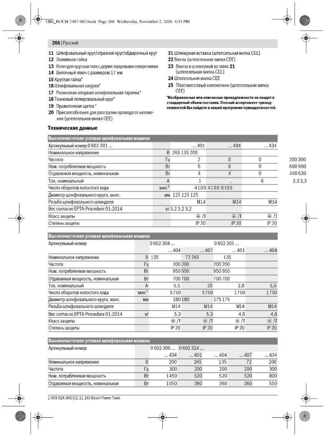
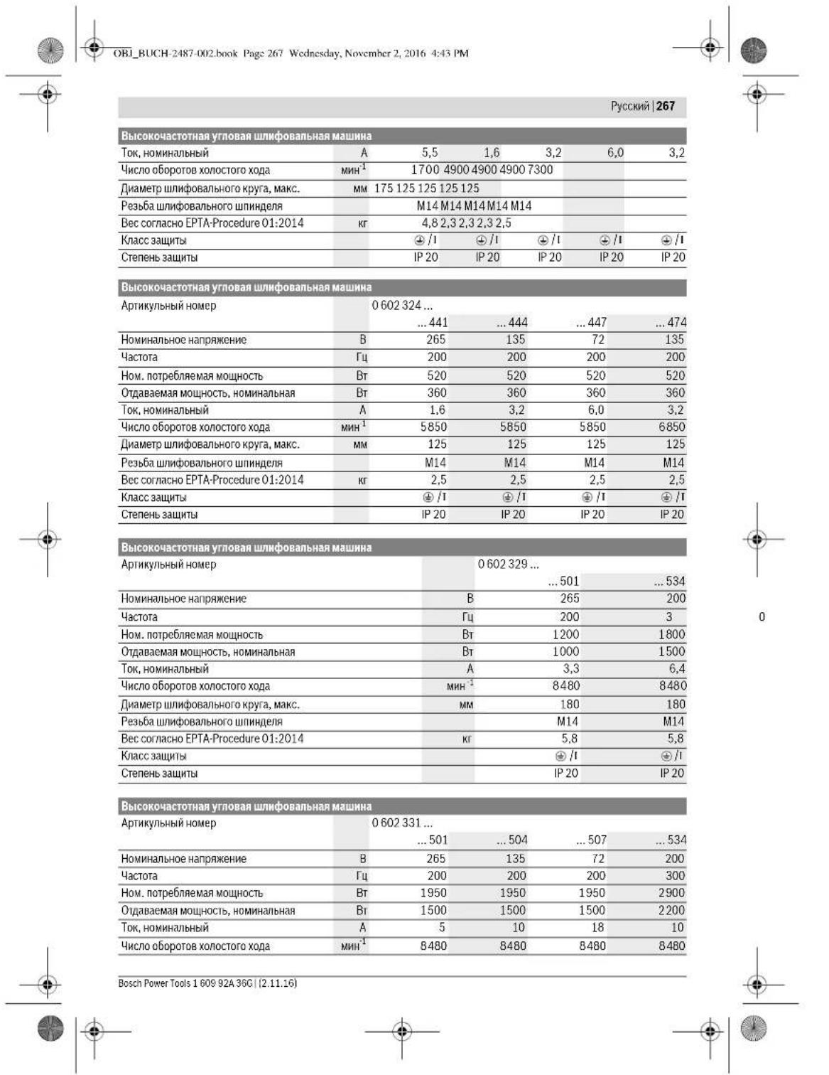
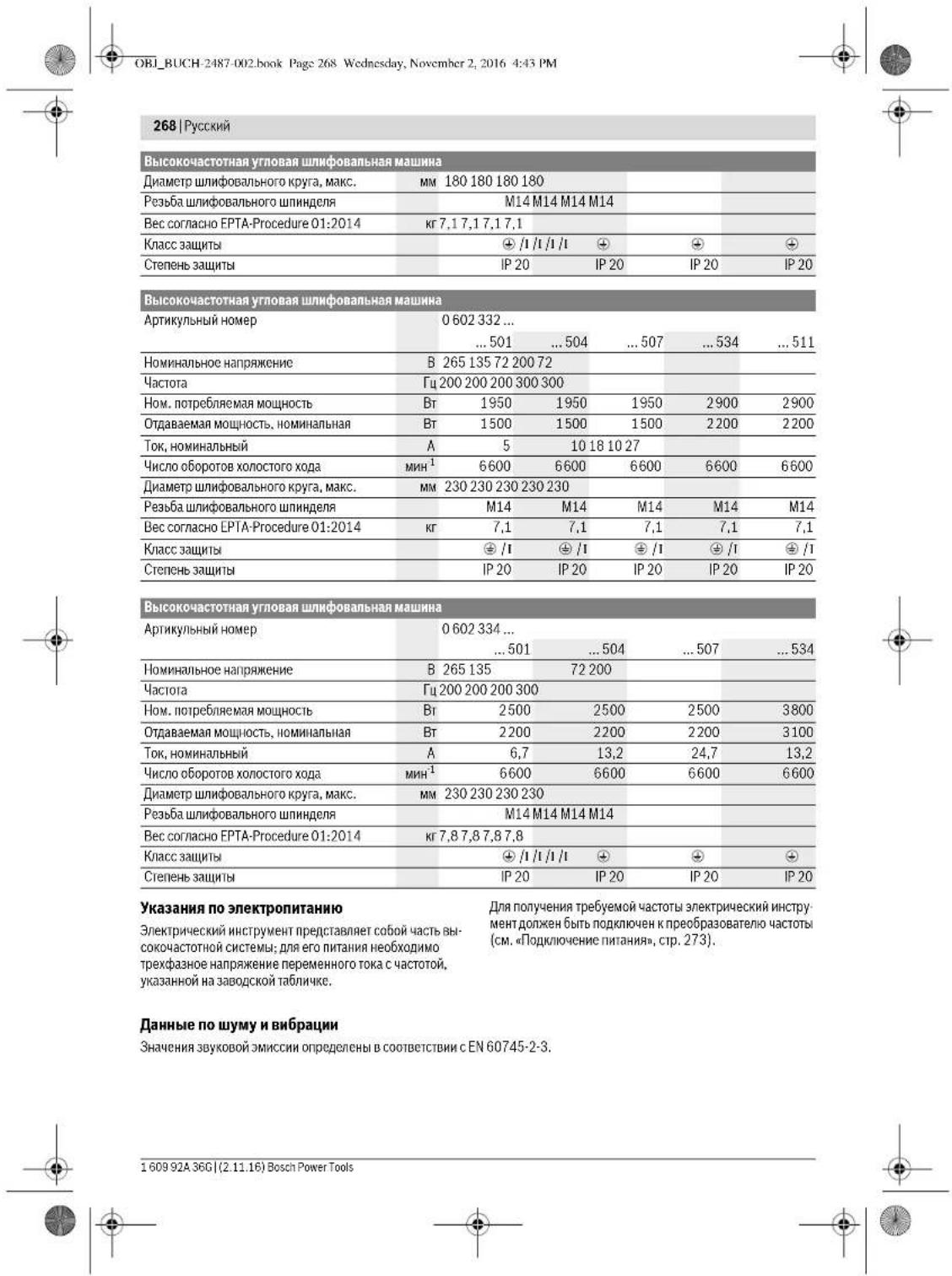
OBI_BUCH-2487-002.book Page 269 Wednesday, November 2, 2016 4:43 PM


| 0602 30140. | 0602 301434. | 0602 304 40. | 0602 305 40. | |
| A-BaBSeHHeHb yPoBeH bIyMa HnCTpy-MeHTa COCTAIBRET TNIINYHOуPoBEH b 3BvKOBoI OJaBHeHb IyPoBeH b 3BvKOBoI MoUHocTb HeNDCTOBepHOcTb K ПгIMHeHЯte cpeIcTaBa 3aunHtBuoprAnOB cnlya! | ||||
| СуМарная ВИБрацья a₁ (ВEVКТОРHA CUM-Ма ТрЕХ HaNPaBIIeHи) И NOTPeSHOcTb K onpeJelenH b COOTBETCTBm cEN 60745-2-3. | 72 | 82 | 79 | 76 |
| 83 | 93 | 90 | 87 | |
| 3 | 3 | 3 | 3 | |
| ШИФОВАНО NOBEPHXOCTN (оБДИРКА): | ||||
| a₁ | M/c² | - | 5,3 | 5 |
| K | M/c² | - | 2 | 2 |
| ПОЛПОВАНО: | ||||
| a₁ | M/c² | 3 | 3 | <2,5 |
| K | M/c² | 1,5 | 1,5 | 1,5 |
| ШИФОВАНО ДИСКOM с abpa3HBHои shkypко: | ||||
| a₁ | M/c² | 3 | 3 | <2,5 |
| K | M/c² | 1,5 | 1,5 | 1,5 |

| 0 602 306 434 | 0 602 324 40. | 0 602 324 44. | |
| 0 602 324 464 | |||
| 0 602 324 474 | |||
| 0 602 324 434 | |||
| A-BBSEHENHII yPOBEH IIyMa INHCTPymEnHa co- | |||
| cTABLIET TINNIO | |||
| yPOBEH b 3bYKOBO r DaBENHII | ДБ(A) | 82 | 77 |
| yPOBEH 3bYKOBoM MoUHocTH | ДБ(A) | 93 | 88 |
| NeHOCTOBepHOCTb K | ДБ | 3 | 3 |
| ПИМЕнITE cpeIcTBa 3aUHTb OprAnOB cnyxa! | |||
| CvIMAPHAA BnBpaUH a_n (BeKTopH YA CUMMa trpex | |||
| HapRabENHII H nOpeLHocTh K onpeHeneHb B | |||
| coOTBcTBN c EN 60745-2-3. | |||
| UHΦOBAHNE NOBEXHOCTH (O6dIPkA): | |||
| a1 | M/c2 | - | - |
| K | M/c2 | - | - |
| ПОЛПОВАнHE: | |||
| a1 | M/c2 | < 2,5 | 4 |
| K | M/c2 | 1,5 | 1,5 |
| UHΦOBAHNE dNcKOM c abpa3HBNo IshKypKoH: | |||
| a1 | M/c2 | < 2,5 | 4 |
| K | M/c2 | 1,5 | 1,5 |
OBI_BUCH-2487-002.book Page 271 Wednesday, November 2, 2016 4:43 PM


Henk Becker
Executive Vice President
Engineering
Helmut Heinzelmann
Head of Product Certification
PT/ECS
y1x1 = 2 y2x2 = - 4
Robert Bosch Power Tools GmbH
705.38 Stuttgart, GERMANY
Stuttgart, 01.01.2017
Pycckn | 271
C6opka
yctahOBka 3aunThbix yctpoHCTB
06uhe yka3aHH
IpeHAcTPOKOH HCTpyMeTHa, 3AmeHOI pHnHaJ
XeHXOCTH NIO TKNADBaHNEM HCTpyMeTHA B CTOPOHYBkNOUaHT eR0 3eKTPoHNTAHHe. 3Ta Mepa
IpeDcTOPOXHOCTN IpeDIOBpaAeH HeIpeHnAMEpeHHoe
BKNIOUYHE HhCTpyMeTHA.
Ykaaahne: Pnnononmke HmfoBbHoro Kpyra 80 Bpemabopobt mnn npOBpeDHHN yctpoCTB KPNENH 3aaHTHRHOKOKQyXa/3NEkPTONCHPTMEna3NEkPTONCHPTMEnDTONKx6bIbHEMeJNEHO HAPABINB E CEPBNCHyO MaCTeCKyO, apeca CM. paoenCepBCnKoNcHcybTnPOBaHa NHePmETNCNBOBAHIOIPOyKHH
3aunHtHe KoxyXh yctanabnBaTae TaK, TTO6bO HN npedotpaasann noETnckp B HanpaBneHHn onepatop pa.
Kyaahane: Kpinyuohue Kyauukn Ha auiuThbix Koxkoyax
PepoDTPBaaIOT B03MOXHOCTb MOHTaKa H aNcKPTmuHcKOM
HhCTpyMeHe He ppeyCMOTpeHHx Hnre Ho 3auuTHbIX KoxkxyOB.
3aunthbKoxynIaIINMOBAAHn (cm.pnc.A) DeCTBHTENBOIeCNEyOuXTNIOB:
-060230440. -06023295..
-0602324434 -06023315.
-060232444. -06023325..
-0602324464 -06023345..
-0602324474
Bctabbe 3aunthbKoKy6 KOpmyuom Kynakom8 B KOpyuohnnnnaeHHnHdien4tak, YObbypHTNK 3aunTHORO KOKyxa npneran K PhaHny 3neKtpueckoro HcTpyMeHa.
- Otperynynpyte nojnoekhena zauhthoro koxkya b3aunch-mocht o1itopbeshcnie paoboyen oneapaini.
-ДиФИКСАUMДИТСОКOДXYA3ATNHTE BINTHФСКИ-
BOBANH7СМOMEMHTOM3ATRKKHHM.10Hm
3aunthbikkoxyxnao1pe3aHH
HcTbnoIe 06230440. -0623295. 06232444
-0602324434 -06023315.. 060233144 -06023325
-0623244. -0602335. 033331436 26887815
-0602324464 -06023345..
-0602324474
Pnpe3e c NOMOsb CBA3AHbix 6pa3HOB BCerda HcnoNb3yte 3aunTHbKoQyX dna OTpe3aHH.
Bercda cnbnb3yte npe3kn kAMH bHTKHO Koxy dnopt3aHH c HAPABHNOHMn CanA3kMn (npnaHneXHc0t).
3aAHTHNE KOKXYNI DPTESAHNA MOHTHPYOTCR AHAIOYTHNO CTANADPHOTY 3aAHTHNOKOKXYNI Cm.PHC.A.
Bb6poracaa daononHHTebnha pykogka

Bb6poracaa dononnn
TeNTHaY RyOKrA TMybHaAeY POryBbH BNuPaRn H o6ecneuBaAeT 3HM BoJee KCMoPfTHyPoB aOby.
PbIyBaeTcEhApTOHcTPymTeOMToNbKcDOnON HENTbHOHpykOeKo 2.
-ПИМБИNTHEДОПЛНITEнгу pyKORXY 2 cnpaba HIN
СССАВТОРЕДУ
bapotb.
Hnueo He MeHnTe BdoonHnTeBho npKoTKe.
He noJIb.3yIteCb noBpeKdEHNHO donONHHTeNHO py-KoNTKHO
3aunTHbH uHTOK pyKn (cM.pHC.C)
DnBtBnBbHO DnCnEduuHx TnOB:
-06023014. -060232440
-060230540
-0602306434
Ipa6oCpe3HNOB0uHnHFOBaNbHOaTapeKo17 HmC qauueHOBuHMcKOBoUeKo,HnC c neneCTKoBBIM uHBOHBM KpyrOyctAHbNBAte 3aunHTHbM yTOkDpykN9.
-3aKpEnJIe3aJHTbHbIyTOK9doONHHTbHbYpykoTOKN
YcTaHOBKaIHHNoBaIbIbIXHcHTpyMeHToB O6uHe yka3aHa
PepenHactpoKOH HCTpyMeHa,3aMenOH PnHAdNekHOHTMNI KTNADbBaanHE MHTPYMeHTA CTOPOHY BkIOVAe OEO NkTPOHNTAHHe.3a Mepa npoctopoxHXOCHn PpOeTbpaaeHnpeHnAMEpeHHoe BKIOVCHNE HCTpyMeHa.
YuHTbBaIe pa3MeBpU uHnFOBaBbHX HcHcTpMyeHOB. HaMepIOPOOHO IOBepTmH DoJIKH COOTBECTBOBaIbOnoPHomy FAnuHy. He npHMeHRe IpeXeDnKnNnAanTepeI.
OuHuaIaTe UINIOPOBaIIHHN IINIHJENJIb 3 N Bce MOHTHPyeMeBte.
Pocne MoHTaKa 1nnHFOBaNbHoRr HnCTpyMeHa TpoBepBeTpepeDkNHOeHHemnpABHbHOcTbMOHTaKa Cbo6oHoe BpaSeHHe NcHTpyMeHa. PocpeBte Cbo6oHoe BpaSeHHe NmHFOBaNbHO rHnCTpyMeHa 63 TeHNr O3aunTHbIKoKxHnIpnDpyThe qactH.


272 | Pycckn
YctahOBka uHnfoBaIbHbIX,OTpe3hIXuHn 06dnpouhIX kpyroB (cm.pnc.D1-D2)
DnCnCnCnCnCnCnCnCnCnCnCnCnCnCnCnCnCnCnCnCnCnCnCnCnCnCnCnCnCnCnCnCnCnCnCnCnCnCnCnCnCnCnCnCnCnCnCnCnCnCn
-060230440. -06023315..
-060232444..464. -06023325
474...434 -06023345...
-06023295.
YctahOBka:
- Y6eJ1IEBc.5 TO, yCTO CHAOHBEI NOXIOJDAJIUMA ZAHTINHMB KOKKy (cm.CYACTAHOBKA ZAHTINHBYC XQETPOCR3A, ctp.271).
- Yctahobone otonpHbI pIaHeu 10Ha shnHPOBaHbHm shnHdE3.
Ha onopHOM phanue 10 Bokpyu cHTpmyoero bpyrna HAOHNIC INACTMACGOSB detanb (Kolbyo Kpyrno CeeHH). ECn KObUo Kpyrno cecHHaOTCYTCTBYETNNOBpeXeNo,TOHOONHOb6b3aTeNBO3aMeHeHO HOBBmpePeMOHAnOMonopHOro phanu 10.
- YctahOBHTe Ha IINHFOBANbHbI bINHIDenB CooTBeCTBHN CnpAIBNbHM HapnABNeHem BpaueHnry HxNbI abpAHHbH NHCPTyMeHNT 11 (InHFOBAnbHbI,OTpe3HOHN O6DIOPOHbHnck) 3.
Hapehhe TaazKMMHyraikny 12 Ha p3bBy uHHHdienrak, ytoBu cpeHHe yrrybnHe He 3aKMMnH raikm CMOTpEn BBEpx.
Kpenko3akpyHTe 3axmmHyo raiky C noomoubKnOuaC yBmTPOUOBMn OBEPCTHMN 13,OnHOBPMEHO yepkBa n NoOMuBn BOuOHOro RaeyHOro KKnOua 14 mD0BaBnBBn MNHNHeB.3
CHATHE
-KpnKOI depKHXTE HINHOBANBHN HINHENELS 3a nopeBHOXCTO BND KNOH INBOHNHYM RAeYbHM KIOUOM 14
OTKpyTHTa3aKIMNHyraKy12HaIINHPOBaIbHMUIHHNE CNOUMOJIbIO KIOHA C BYMMA TOPOBMbIM OTBEPCTHRM 13.ODHOBBPEMeHHoDEpXac3aNoBepXHOCTbIO KIOHBOHNHO BmAEHbIM KIOHOM 14.
CTAHNATE NO3TO 0BAP3HNBHB HCHTPMENHT, A TAKIOE ONOHPH PHEAUH C WPHONFAHBO HTHINHNJEL
3neKtpHueckn HNCTpyMeHT C KHONKoΦHKCaHHHHeIe 5
IeHCTBHTenbHo IINr CnEyUOxH TINOB:
-060232440.
-0602324434
-060232444.
B3eKtPHUcEChXHCTpyMeHTACx C KHIOKΦmKcAICuINuHINH-5O TnIaAdet Heo6XOmmOCTb yEepKaHuaNInHINeC nOMOUBIO BUNHOORO raeuOHNO KnoHou cM. pHC.E1-E2).
Haknmaite Ha KhoNky KfKcAaun HnnHdena tonbko npoctoaHOeHHo HmHneBn BpoTHbOM cnyae 3neKtponctpmyMeR bhtb nopeKjEh.
- IpeepIcnoIb3oBaHHeM UINHPOBaIbHO HHTpyMeHa HAKMITE XOHNONY DHCKCAUIN UINHHIDEN5, TIOBb appeTnHO Bt UINHPOBaIbHbIbHII INHHIDeB 3, H depXHTe 3Ty KHONKY HAKATOJ.
- YctaHOBIne HUYKbHb 6ab4aMbHb HnHCTpyMeHT (CM. #YCTaHOBKa 5nnHpOaBbHbX, OTe3HbX INN 06DmPoHbX kpyroBx, ctp.272).
-OrnyctHTKKnKpy dKcaHHHnHnHnEa5,HTo6bCHnTb dKcaHHO.
MONTAX pe3HHOBON onOpHON mHFOBaIbHOI TapeKN (cm.pnc.F)
DeHCTBNTeNbHO DnCNEyOuNX TINOB:
-06023014. -060232440
-060230540.
-0602306434
YctaHObKa:
YbDHTBCTB TOM, 4TO YCTAHOBHn 3aJTHHnI 1UHOKpyHK HIOJIINHHeJIbHaB pyKoTIKA (CM. yCTAHOBKa 3auHITbIX xycpOeTb, crp.271).
- Yctahobnite peHHoHyo onOpHnyu mKpOabIyhu TYapENKY 17 HaunHpOabNhyu hnHnIeN3.
JIOHOJIHTeMHoHOBaIbHyIOuKyI61He naEHHOByIO onOpHyIO uHIOFOBAnHyTOpeNky.
- YcraHOBnTe KpyrnyIO rAky 15 Ha pe3b6y WnnHdena.
KpEnKpNpKpyTHe KpyTnyo rAky C nOmoUbI KnOuCa c DByMTOI0BbIM OTBepCTINHm 13,OnHOBpeMeHHo ydepKbBAa WnDpoBaIbHbWnHnDnE 3aNoBepXnOCTb NOJKnOc NcmOIOuB BnNOHOrTO RaENHOrKnO4 13.
Pm3TOM cneHnTe 3a TEM, yTOb6 kpyrna raiKa 15 nonHOCTBIO BOYNA B BEMKU B PReHHOB O npOHIOI INHFOBAHBOH TAPeNKe C TEM, yTOb6 OH a He MeWana BO BPREM IINHOBACHN H KPNKO YepKXBNA bH NPHOABNHy UOKPYK.
CHATHE
-KpnKIOIepKHeTMeIINHbOaBHLHINHIIeHN,3aNobEPXHOCTbNOI KIOI HIOINBIOHJI MAE BAHBI HIKQNQM14
OtkpyTHe Kpyrnyo raky 15Ha WnHpObaNbHom WnHHeNe cI POMIOJIbKO Hcy a CByM TOPOBbIM OTBepCTHMN ME OHOBpeMHoD XePaxc BNIQyHbIM RaeyHbIM KHO4OM 14a NOBepXHOCTb NIOKHO.
C H M I N T E W H N O B A B H Y O U K S Y K P E R 93HOBYO O N O P H Y O H N H O B A B H Y O T A P E N K Y C O M I N D H O B H N O H U N H N D E N.
MOHTAKTKAHEBORO nonHPOBaIbHOro kpyra (cm.phc.G)
DeHCTBNTeNbHO DnCNEyOuNX TNOB:
-06023014. -060232440
-060230540.
-0602306434
YCTaHOBka:
Cnepnta 3a TcBbpeBaTKeHBoTOnIpoBAnbHOrO KpyraToHO nOoWNaK peBSe WnHpOanbHOrO WnHdenn (M14).
- YBdHNTcB B TOM, 4TO YCTAHOBIN3AaHTNHbIaHTOKpyKn HIOONHITbJIbHaY pKoTtKa (CM. aYCTAHOBKa 3auHTNbIX xycpOnIcTB, ctp.271).
HakpyTHTKANBbI NIOHPoBaIbIbIKpyr18HaNkoBbIbIbIMINHdEbn3AChtoBko,QTbObIHONKPOnPIenFAIKNOBEPXHOCTNOIKNOKHOHNFOBAnBOHOTINHIDEN,OIOBpEMeHHOYDcPKHBAIINHOBAnBbIbIMINHdEnB3aNOBEPXHOCTNoIKNOKCnOMOuBbBNIOHOrHOKnOa14.
1609 92A 36G| (2.11.16) Bosch Power Tools


Pycckn 273
CHATHE
OTKpyTHTyTOYCRHUNTKAHEBbMOHNPOBAHbHbKpy 18coIINIOBOANBHOIINHNDEB,3BNNHCb3aNOBepXHOCTbNOJNCHOUINHOHBMTaAHHMKNHOOM,0HOBPeMHHO DEPXAcb BINOHOOHMBeAAHNMIOHOM143a NOBEPXHOCTbNOJ KHOH HAINHOPOBAHbOMHNHNDEe3.
MOHTAX npobonouhbx uetok (cm.pnc.H)
IeHCTBENTbHO DnA CNEyUoMx TINOB:
-060230440. -06023315..
-0.60232444 464 -0.6023325
474A434 -0.6023345
-0.6023295.
YCTaHOBka:
CneHrTe 3a TEm, Tc0b6peB36Ba npOboOnoHoi uTckn ToHNOoIuHa K pe36Be uHKnfoBaanHoro uHnnndena (M14).
YbdeTBeB B TOM,TOYcTaHOBtEH 3aUHTnTH bUHTOK pyKHN DNOJINHTeBHbA pyKOTKa (CM. YcTaHOBrA 3aUHTnTHbXy TycpOBrCTb, ctp.271).
HakpyTHTRE HnyKno npobOAnHy Oteky 19 (naeAeyHOHnNIOKBOy) Ha nIHOBoAblbHnnHnDcB 3 HAcToBNo KTObO hBaONa KpEnKO pRnHemaN NOKepBXoCTN NOJKnO HINHOBAHBOHOrNO HInHnDE, OIOBpeMeHHo DEPKaC BINHOHM KIOYOM 14 3a NOBepXHOCTb NOJKnO HINHOBAHBOHOr NINHnDE.
CHATHE
OTKpyTHe Tpy CnHnHpy NpOBoNOnHyNpyIeKy 19 co nIOOBaBnHO Horo mnHnDEna, B3BwHbC 3a NOEphXHOCTb NO KNOY BnNOyHM RaeyHMH KNOYM, OJHOpeMeHHO depXcb BnNOyHM RaeyHM KNOYOM 14 3a NOePbXHOCTb NO KNOY mnHnHfoBaBnHO hnHnDEna 3.
Otcoc nblin H ctpyckn
■IbIbHEKToBbIX MATEPAnOB,KAK HAp.KpAcOK C COJIePKAHEM CBNHIA,HEKTOBbX cOpTOB JpeBEcHHI, MIHePAONH METANIOB,MOKeT 6bItb BpeHNOI dApOBOB.IIpHKOCOBHeH K bINH NnonaDnHne bINB bIXaTe TbnbIc PNY MoKET 83BaTb AanePnueCkne PaeKnHN HmN 3abOnBeBAHn BixATenBbIX nyTe onepatopn HnHXoDaerocBbHN npcoHana.
OngepehneHbIe Bnbln HnH, nAby6 hNkCvHTaKr CHauepeoRcHbMnO,OC6Eho C0BMe3HO cPmCAdKaMN JnroobapOToKn IpeBeCNHb (XpOMAT, cpeCTBOJ 3a- mItti bpeBeCNHb).Matepan C noCpeKaHmHN aecbcta PapeaeeChocBaPaBtTtoNkHo CneuHNTCTAM.
- No BO3MOXHOCTN HCNJb5yTe npHrOJIbI DnMATEpHana NblneOTcC.
XopoO npoBertPbBaIte paoboe MeTo. - PeKOMENyETcRnIb30aBcTbcpeCnHpATOpHO MaCKoCΦnblTPOmKnCaP2.
CoNIOaIteKeDcByOuHe BauWee cTpePepNa HIN DnOcbpaBlaAeMbx MATEPHNO.
H3eAeKcONNeHHbHnHaPbOeMHMeTe. HbMOKETJIKTOBOCIOJIAMeHTBcRb.
IopknIOeHne HHTaHH
ДЯЗКСПЛУATAQUIN 3NEKTPUeCKOFOHHTPYMENTHA Heo6xOHN PNEO6PbAOBATENB YACTOTBI, BByabATbBAIOUIN TPEX4aHHeO HANPRAKeHNe HEPEMEHHOI TOK aCTOTON, COOTBETCTBYUoiy KyaahHHN Ha 3ABOpckn Tabnue HHTPYMEHNTA.
Bbnyckaembe npoebpaaobateHHactoTbHMeot paaHHue HpaampeHpaanHHie hactoTbpaanHHie BTOpHHue HpaanHHie HpaanHHie HOMNHAAHbouMooHCTbHb60bppe npoebpaaobateaactoTb3abNCHTOTnOeKnIOVAeMOEro 3NepKTHcFOHOHCTPMAETHe.1PpOKOHcyTNbHYPeTEbPnBB60pe npoebpaaobateaactoTbY cneuAnHCTaHpMBo Bosch.3NeepKTHcCKHNHCTPMAENTocABNTmecCo COneauAaHbIMhuyom dnnHOHytpe MeTaBe3WtencbcNBOHNKn.1Peep3aTcKMOHCTPMAETBaKcNpyaAuaHIO TOTcNEauAhnBnHyp HeNoXoDHomNqNOHbKytBepxenoNCHoh WtncEbnBnHNKe CEE (seneho rba).
KpmeToro, 1n3auntbIeNtPnEeCKTOHnCTpyMeHTaO npepy3xN Heo6xoHMO NoCTabNobbHHuHn SAUHTBn AB TOMATeNekTPODIBRAtAE. DnAhaSOn TKOB ACHPOIN3T0r OaTHNOrTO ABOMTaDOJKNKHepeKbByBaTbHOHNMAHbHbT BOK NekTIePnEeCKTOHnCTpyMeHTaCm.《TEXHueckKeH DAH Hle').3auNTIHbABOTAMeNekTPODIBRAtenDoJHKcpa 6atBbTaBbBnB p nepeanox dOioH cekHyBu
CobIpaIeYkaaHnN oTeHXKHe 6eONACHOHT HnCTpyKuTHo moTahgyTc,coedPaxAaeebE ykoBOcTbeNo XCNpUaATIN huaNTHO rABOMATA nEKeKTOBnARtelaT
MOHTAX wTeNCenbHOB BNNK CEE (cm.pnc.1-12)
- OKTPynthe 06a BnHTA 22 HbHtbe tIeKepHyO bCTABky 21 N3 KOPNYc IeTcBbHbN BnHNK CEE 24.
- Otpxbtne IaactMaccBn HakoHeHKn 25 B COOTBeCTBnC DAmETPOM CnepnA hBO rHpya 3neKTPOnHCTpyMeHa HADBnBte KopNc UTeIeCNbHO BNKK CEE Ha CneuHaBnBn Hhyp.
- PobrejneIe TchTpe Propobla Ikhura Ypez3 IcHIOscOBeNIE NnIeIaPpTaYnKPiPbODoB OIT HATRAKHeN 20.
OtKpyTHe TbeBbpe HeBoIbux BnHTa 23 B uTekePHoB BCTABKe 21 H BCTABTE KOHByo TMhby KOpHHeBSo npoJa L1 B KOHTAKHOE rH3do L1.
KOHJEBYO rHb3y CnHero npOBoA L2 B KONTAKTHOE HTe-3do L2,
KoHHeBryrHb3yEepHO rnpObaL 3B KOHTAKTHoe THe3do L3, a KOnHeBryrHb3yJxEeTo-3eneHOrO npOba B 3aaiHTHOeTHe3do
CHOBAKPENKO3AKPYTHTeYbIpeHEbONBbIXBNHTA23B WTeKepHO BCTABKe 21, YTO6bI3aKpENHt3THcTbIpe npoBdo hUpya.
3Atem 3akpyHTNE PnHcNOcbneHHe pnaarpy3kn npOBoBOT HATKHEH20 BOKyTBCero UHypa C OBOHOKHOHACTIObKO TYO,TObHa KOHeHBe TINb3bI npOBoBHe DeCTBOBAHNCHAHATKHeN
- Bctabbte ItekepHyo BCtABKY 2B KnpNcI tnteneCbHbno BNINCK E24 NCHobaKpenko zakpytute OBA bNTA 22.
B3aknHounepePOBpEbeTcYbHKUHOHLbHyCNOcO6B HOBPOBAD3aUKTHORo 3a3eMENHJI.

274 | Pycckn
BCTaBbTe WtencBHyBO BnKc CEE 243eKnHcTpyMeHaBpo3ekyIpeo6pa0BaOBeTnAactObl.
TenebMOKHOIOJIOJIIOUHTIpeo6p3OBAeITbNaCTOBIKINTAIOOCHETN.
O npnqde npoknoueHnnpo6pa30baTeTnacctToK nIHTaIouie cetn npouhTaTE Bero hNCTpykun no 3KcnPyatauun.
B3aknouehne npoBepbTe hapabnene BpaueHH! PnpoBepka hnapaBennn BpaueHH
Hapnabene HbpaenHnnnfoanbHoro nnndJeonKHO coBnIaBcO cTepknK,KnobpaexHno Ha nKeTPOHNCTPmEnr.
EcnnnnnoaBnHn nnHnDnB npn nepBOm 3nYcK E KnnyatauO (CM. BKnIOeHne HbKnIOeHne 3NkTPOHHCTPmEHNTA,CP.274) BpaauaTcRb HENpBaHbHom HapBaNEHN TO HEMdNeHNO BknIOHte 3NkTPOHHCTPmEH NTKIOHTE 10rO CTCEMb 3NkTPOHHATAHN.
CHOBA OKPYTHIE 6a BHTTA 22u BuHbE tUeTekePHYIO BCTABKY 21u KOPNYCA UITENCENB MuNBI KEE CEE 24
- OTKpyTHTHe BbHbTe KOHeYHeIe TnBb3b KOPHHEBOGO HEPHERO PPOBOBOB I KOHTAKTHUH TheaI.
BCTabBeTneOncE3TOOR KOHEnHyIOIINb3y HEPORo npOBogaD B KONTACTHOeTHED0L1,aKOHEnHyIOIINb3y KOPnHEBOrO npOBogaL1-B KONTACTHOeTHED0L3 - CHObA KpeKo 3aKaYrTHe 6bO7uIe BnHTb2 23 WtKeepHOB HcBtBe2 1, YOb6a 3aKaPEnHbIPOBa.
BcTabe8teUtepeKINr BcTabe8Y 2B KopryCtuneceBnHIO BnHN CEE 24 n ChOba KpEKOaKpyTITe OBa BnHTA 22
B-3aiknoHHePOBpeTbYnHIOJIaHbHyNcO6b HocBo TPOPODa 3auTHOro 3a3eMEnHey.
-Пдогкунчerte3нКТРИСЕСКИННСТРУМЕТКССТЕМЕЗЛКТDPОДИАНОВ.
Pa6ota c HnctpymehTOM
Bknouehne 3nEeKtpoHnCTpyMeHa
HAnPraHenHe NactoTa HCTOuHNKa NITANHn DOINKbI COOTBETCTBOBaTb DAHBbIM Ha 3aOBcKn Ta6NtKe 3eKtpOnHCTpyMNTA.
PnpoeepaHnHPOBAnbHbHnHCTpyMeHT npnMeHHe. HmHpaHbHnHcTpyMeHT Doxhen 6bItb63yIpeHcOYtAHOBHeN CBO6DHO BpaATbC. BbIOHNTHe pObHBe BkVOnueH Be TceHHe HE Me Hee1 MmHTb63EHpRy3KHe. H npHMeHaTe NOpeXJHHeIe HnHCTpyMeHTb N HcHPTMy, HmEOoJIe OTHNOEHHr OOTyIOCTn HIN B6pHyoJe. NopeXeHHBe HmHOAeHHBe HnHCTpyMeHTb MOyT PaOpBaITc HnHaecTI TaPbMb.
Iocabte BbKnoateB 1 B noXeHHe BbKn,
ecn HJekTPOHCTPmEHT HeoHdHaHO octAHOBTCB
BO BpMa pObToHcEMOTPr Ha To, 4TO BbKNoATeB
haoNTBaB NO bONooHcE BKn, 3THM npoeTbpaaET
BCO3MOKHOCTb KEOHPTPOHPyEMTO IOBTOPHO 3anyCk. PpeD NOtOPbHM 3anyckOM 3neKtPOHCTPmEHTa
npoeBpe TnAnHe (CM. IIOKIOUOHHe NnAnHs, ctp.273).
Bcerda chayana coedHHnIte 3neKtPOHHCTpymertC npe6paobatoTeMaTcb, npexde eemnoKpHIOuYb tbepeoabOaTeBa TcAOTb KnHbAoet CEtH.
BENXKIOHMOI NEXTKPOAHEPIKN BIKHOHAIE NEXKPTOHNCTPymeNTOINBOKOTDA, KOrDa Bb coBNpaTeBC paBoTaB C HMM.
BKnOHeH N BkKnOHeH npeo6pa0baTeTn aactToTb CnaHApN HeoXoHMo 3aYcTiH b DcKtBHe Npeo6pa0baTe Tb cactToTb, npKeJe Me BKnOHaT b3eKtPOnHCTpyMeH. CoNkoHte pRn stOM yka3aHH HnctpyKuHN No KcCnIyata LInn npeo6pa0baTeTn aactToTb.
BbKIOUHHe N bIKIOUHHe 3eKTPoINCTpymeta C npedoxpaHTenbHbIM nO3yHKOBbM BbIKHOaTeMe (cm.PHC.J1)
AeBCTBbHbOaIaCNEyOuXnTHNOB-0602324.4
-1BnKIOHENHNEKPOHCHPTyMeHTa nepeHHbte BKNHOATEs 1BnREpe.
-ДиФИКССРОВАЙНБКИЧЕНИНЮВБКИCHNOTAHENI1HAKMITEHAHERCIOPEDAIDFOKHIССРОВАЙ.
Yro6bBbKIOHTb3eKtPOHCTpyMHT,OTyCTHTe BbI KIOHaeIe1.
Pn3aKcHpObaHOM BbIKHOATene 1 cnerKa HAKMN Te e0 C3aHnBH3N 3aTeC OTyCTHe.
BklioueHne HbkioueHene 3neKtpoHcTpymeta C npedoxpahntenbblm BbkIOaTeNeM (cm. pnc. J2)
DnCTBNTeNbHO nIa CnEduoHx TnOB:
-06023014. -06023295..
-060230440. -06023315..
-060230540. -06023325..
-0602306434 -06023345..
-ДалКИУЕCHOМАЗКЕPGHСТРУМЕпЕВБИЛБЕВКИОЧАLEБПЕРДЕСТЕСТЕСТЕСТЕСТЕСТЕСТЕСТЕСТЕСТЕСТЕСТЕСТЕСТЕСТЕСТЕСТЕСТЕСТЕСТЕСТЕСТЕСТЕСТЕСТЕСТЕСТЕСТЕСТЕСТЕСТSE
-ДиФКССССССССССССССССССССССССССССССССССССССССССССССССССССССССССССCS
-ДыьькIOUeHЯнгEКTOPOHHTCYPMeHAOTCYTHe BILKHOuATeHb 1Mn,ecNn OH ZaIFKnCPOBaH,HAKTMEKOPTOKHaBOHcHbI HAtETOM CYTHe erO.
Yka3aHHNo npHMHeHIO
IpepeHactpoKoHnCTpyMeHa,3aMeHOIpnHAnJekHOCTeH NIOkTNkDbBAHNHE MHTPYMeHATB CTOPOHY BbIKHOaHTero 3NeKPTOnHHe.3aMepa IpeEOCTOPOXHOCTN IpeOToBpaAaET HENPeHAMEpHHoe BKIOHcHHe HnCTpyMeHa.
OctopsoHO npn pOdoBaanHnAa08 B KAnTaNbBHX CTehAXC.M.paTeJcYKa3aHnNo CTaTHKeK.
3Akapnnnna 3aTAROBK,ecnHcnecoBbHeNbBcHe 06echnbaetaedaeHHoeNoXeHNHe.
HeHarpykaaTe 3NeKtponHcTpyMeHT Doero octanOB-KN.
P6aouHHHcTpyMeHTMOxHOoxNtBnOceBbICoKo Hary3K, DABemyNoPabotB BTeHNHe HCckNkHXMHYT HXONOTOM XOyD.


Pycckn 275
UHFOBaHHe BeepbIM UHFOBaIbHbIM KpyROM
BeeHbIMnHnObaBbHbM KpyrO (npnHaDnEeKHOCTN) MOxHO TaKKe 06BaTaBbTa BblNyKbIe IIOBExPOCHIN HPOPHIN (mHOBaHHe KOHTyPo)
BeePihe 1nHpOaBnHbIe KpyTH 6nabAOT 3nAHTenBHO B0bnHIMC pckOM CNYkbl, COJdAOT MeHbU npOBeHN WMy M n HbUme TmepApTyb IINHpOaBHn, HEM OsbHHe NnHpOaBnHbIe KpyTH.
Pe3ka MetTannna (cm. pnc.K)
Pnpe3e c nmoobb CBA3aHbix abpa3mbOB Bcergda HcnoB3yte 3aunThb Koxyx dnn OTe3aHH.
PnOTpeaHHHINHFOBAAHBIMKpyrompaobatameCyme-ehHO,COOBETCTBYIOUeOBpabatBaEMOMyMATEPHany,ndaey.HeokaaBbteaeBaNHEHaOTpe3HOKNpyr,HepekaauBaHReHKeKaaiyeero.
He3atopDMKaHbIeOTpe3HOnKpyHaBuiBeE6oKOBUMdABENHm.
Bcderda bedite anektoponhctpymeh npnoTH hanaPbneHnHa BpaueHHN. I pnoTHOBnCluyae BO3HnKaAeONaCHObHe NekOHpOnHpyEmo BxOkaI3 nPOpe3N.
PnIepeKs npOJIeHnI HHTeBpEaTHbX Tpyb HauHInHte PEs HA NAMHeuMbeN noNEpeHcO HcEHey.
Pe3kaKamHa
IpnpeaeknKaHHMaOBecneBteOcTaOHTbHOrOTcCnbln.
PnmeHne npoTHBONbIneBOpecnnpatop.
JaHHbI 3nEeKTPoHnCTpyMeHT pAsaetc npMeH HnTb TOnkO JnA cyXOr opeaHnn H cyXOr uHnfoBaHH.
IpaesKAMHnyBceroHCnONb3oBaTbnAm3hBe OTePbHeNDCN. Bna3aunTbOTnepeKaWbAHNR dnJXeHN HCnONb3oBaTbCnTRKHOKQyDnOPE3aHnC HapAaJIIOHMn CanakamH.
PabotakTe TOnbko CnBneCocm HdoonHHTeBhoHCnoB-3yIe PpTHBOBHeBopeCnHPaTOp.
NbneocdoJnKHeHKMtebDonyckHaOTcAcBbaHHeKAMeHHOH
bnH.ΦpMa Bosch npdIaerat cooTBeTCTByOuHne bnecoC
cb.
BkniouHrte 3nKtPOHHCTpymHrN UcTaHOBHTe erO nepeHne TaactbHO HapabraOHxCana3oKHaTeIb. IpepeMeHAne 3nKtPOHHCTpymHrC yMepeHON, COOTBCTBYIOuE OcbpaBbBAEMGY MATEPHY Noadayi.
Pn6ob40ke 0c06 TBepeBix MATEpHAnOB, HApNMeP, 6eT0A C BbCOKM C0eDPEKANHEI PABIN, AnMa3hBt OPe3HNO Kpyr MoKe NpepeTcBcNbBbNObpeKJeE. BpaauoHmca C anMa3HUM Ope3HbIM KpyrOM CHON KCP OHOHaHOn Yka3BBAET HA3O.
B TAKOM CNYaiepepBEHTEPOeCC N DaJIte aIIMa3HOMy OT- pE3HOmy KpyrOy eoctbHa XoIOCTOM XoYi PHN KAKMIAbHOK cKOPOtC T BENEHUE KOPTKTORE BPEMeHN.
3HaHTENbHOe CHINKHe NPOHBOHTENbHOCTN H BpaAIOHNCI CHONHKP TOBOPRT O TOM,TOA ANA3HbO TpE3HOH Kpyr npTynnAC. ANA3HbO TpE3HOH Kpyr Bbl Mokete 3aTOHTb KOpOTKIMM PE3AMH B AB43AHOBm MATepHAne (HAIIHPMEp, B CNIHKATOH KPIINHE).
Yka3aHnH no cTaTHke
Na ha3b b KaanHaihBx CTEnax PaacnOcptPahReTc HOpMa DIN 1053 paactb 1wnH CteuHPhHHBeI dcooTbeCIByuee ctpaHb pnoenHcHnn.
37NppePnHcAHHaIeNtKbO83sTeBnHO bIyNoHNHTb. 10Ha quna paobToI npokOHcyIbThpyIteB cyOBTeCTBeHOrO cneAnHnCTo noCThKe, apXHTekTOpA nnNpOpaBa.
06dpoohoe uHnfoBaHne
HnKoHa He npmehaite oTepehbe kpyr dnn 6bnpkn!
Cyrnom Kpyra ot 30^ no 40^ k 3a9otobke Bbl nonyuhte Hannyumhe pasyntatupabotb npn obnpnoHOM mknipboahann. IpepeBhrAte 3neKtponHCTpyment CymepeHHbI pinnxamet Tya n o bpahtno. Pnp tOAmT OTOBka Cmblho He HaraPeBaETca, HE KImehReT CBOE OKpackn H he OCTaeTc Kahanok.
HnHbAHme HaxdauHOH uKpyKoHa pe3HHOBOnOp HOHnnHOBaBHOH TapeKe
Bb60p noxdxqueh NkduaHn 3KUPKHN 3AUBCNIT OT o6paBaTbIaMOrO MATepHana.
ΦHMaBosch npedraera HauaHbYe uKpyKn paJINHOI KaeCTBa, noXoAouHe K onOpHOI uNFOBaaHbTapeKe. PpOKOHcybHpyeTc b cyueHnAPTnoPdAbuA.
NonpoBaHHe TKaHeBBbIM nonpoBaHbHbIM Kpyrom
PnHONPiPOBaHN CpeCDTO DnI ONPiPOBaHN HAn HOCTNHa 0bpaOaTbBAeMaB MATEpHaN NIN TKAHeBbN PONPiPOBaTbHn Kpyr H BO BPeMa BPAeENH PaCpPeJeAETc NO BCs OpbabTaBbMaEOH NopeXHOCT.
EeINIIOHPOBAHNE BbIIIOHRETCBHECKOJIbKO 3axoIOB CHCNIOB3OBAHNEM PnK KAKDN3 axoDE NOIpyIOEero CpeCTBa CMeHbSe 3EPNCHCTOBo,TOI INNOHPyIOEero CpeCTBa PAaNIHNOEPIHCTHOHe6OxIMHOcNIOB3OBAbT OeINbHbTKaHEbBIIOINPOBaHbHbKpyr.
TtatahenhoOuHnAteNoBepExNochtobpaabatBaEMoRMOmatepnHaIpepeNaHmKaNDoroCnedyUcero3axoJaonipnoHHpOBAHH.
Texo6cnyxmbHne H cepBnC
Texo6cnyxHbAHHe HouCTKa
PepnHCTPOKHNCTPymeTA,3AmeHOI pNHaJNEKHOCTHNNOTKANbBAHHEMHNCTPymeHTB CTOPOHYBkIOHauHrE O3NeKTPOHNTAHME.3aMepa npEOCTOPOKHOCTNPoTbaaET HENpeHnAMEPEHHOE BKNQOHHEH NCTPymeTA.
AaOeCneHnKaeTBeHHoN H630AnchpoBaoB Ta cyeT NOCTOHNO COepKbTa 3NEkTPOHNCTpy MEHT N BENTHNIIOHNO HIEI eHb HcOTHe.
Pn3KcTpeMaIbHbX yCnoBHX paObIbBcerda HnONb3yIe NO B3MOxHOCHOnTCaBbIaOooyeCTpoTHCTBO. XaHTPOJPOBaIe BENTNauOHHbIE 10nIOKnUoayHe NHTCPMeyEe3YCTPOHCTBO 3aunHO TPOKNOEHNA (PRCD). PnOcbpOKe MTaIIIOB BYTPn3NEKTOPHONHMeYMAOTKOTKIAIBATCBTOKIOPOBouHbIbMb. 3tO MOKET MeHbTAHEChu7yep6 3aUNTHOHOJIIN3NEKTOPHHCTPMHNTA.
276|Pycckn
Peyrnapho K3Mepnre 4HcNO o6pOToB xOnocToRO XoDA WnHOBnHO HmDnEe. CnK3MpeHHeo 3NaHEe OHNAET OYkAAHNO OcNcA O6pOToB XoNcTOxo XOA B6NbUyO HmMeHbUyO CTOpOH 60bnue, qem HA 10% (cm. TExNHueckne DAHNIE), TO He6xOIMO OaTd A3ekTpOHCTpymeh A npoBepKy B cepRCHyMoMAcPc6yO cHmPyB Bosch. PnCINIKOM 60blHOM YHCNE o6pOToB XoNcTOxo XoDA 3eKpOHHCTpymEH MOKET NONMTcA, a pIri CNiHKOM H3KOM YHCNE o6pOToB yMeHbUAETC pnoH3BOJNTenH HOCT paobt.
NcnoB3yte TOnO OprHnAnbHbI hUpy HtANHARI NpepeKaKdbM cNoHbOBaHHe 3NeKToPnHcTpyMeHn Ta PNOBepAe MCNPABnHObTHuPy tINAHARi MHTENCbeHbHNb.Bo n36BeKanHe KAKx-Hp6o PnKOB bHyp R uNTenCeBHy BnIKy HeNbIa pEmOHIpOBaTb, a HyKHO MEHRTb HA HOBIE.
NopuyaTeBbOnnHeHrTexoCnyXBaHHnpeMoHTa TOnkBOKBAHNHmPBOAHNOHMy NpcoHany.3mH 06ecneHBAeTc coxpaHIOCTbBeaONaHOCTM3eKTPoHNCPTpyMEHTA.
OuHuaTe po3eTKK, MyfTb HwTeCenBhIbe BnIKK OTHKIOHcHOrO TINrAIOUeH CETN 3NEKTOPHCTyPMHTa CYXON KTAHbIO, He HMeIOUeH BOPCHOK, YdAJIHTe PbIb NactHKnRp3N.
Nocne nepBbix 150 paoHx vacoOuycHTne pedyKtrop cnaBbim pactBOPhtien. CnEydy yka3aHHM rIOTOBHEnA pactBOPtien noPmpeMeHHuYnTHyMa3HIn. Pocne ttoC mCaJItepeyKtrop cneauhBHOpeyKtropnOH CMA3Koi Bosch. Nocne nepBooOuycHTKn NOBtPOTRE 3Ty npoeDpyuC HIEpBOM B 300 paoHx vacoB.
CepBnCnA MaHcPcknФ HPMBo Bosch BbIIOHReI TaKyo p- 60by BctroN aHaeKeHXO.
EtnpIpeByeTOMNEHbIHyP,ObpaAHTeCtHaΦpMy Bosch HIN B ATOPTN3OBAHYIO cepBNCHIO MaCTepCKYIO INA nENPKTOCTPMyROB Bosch.
3aboTnBOxpaHHeNobpaaItebc npHaNDneKHOCTM
PpHnHaIeXHoCTN
KomNeKekChyI npOrpamMy kaucctBeHHbI npHnAaNkHeocTeB Bui Hndere B mHrePheHa cTpaHue www.bosch-pt.com N www.boschproductiontools.com n y BaWero cneuaannnnnoPobaoHHoro dInepha.
CepBc H KOncynbTHpoBaHne Ha npEpmet HcNoIb3OBAHH npOdyKuHN
CepBncham MaCTepckan OTBETHT Ha Bce Baun Bonpocbi no pEmOTy HOBcYKNBaHIO BaWero npOdyKHa n 03aHaCTM. MoIaKaHne YpeTeXn HnFOpMaHIO No 3aHAcTREM BbHaidere TAKOE NO apDCy:
www.bosch-pt.com
KonneKTHCOTpyHKnOB Bosch, nppeOCTaBnHouN KOn cyIbTaunHa nApiedMeH cHIOBbAONHH pOyDkynn, C ydoBbctBmE OTBeHT Ha BCE BaanBONpocb OTOHCOTeBHOra HAuePnyDkynn H e PnHAnHEKHOct.
PtoKyAHTa,Bo cEXE 3APOCax HsKa3ax 3aHCTeR 683aTeBHO yk3bBAIte 10-3aHnH ToBapHbH OHeMep IIO 3aBcOck TOBANHKe INENIN.
Длретнога: Pocchna, Бенись, Ka3axctah, Ykpanha
IpaantHnHoe 06cJyKbHaHe H pemOH 3neKtpo- nHCTpyMeHTA, C cO6NIOeHN M TpeOBaHH H Hopm HTOTOBETE IPOH3BOgTc HA TeppHOpHH BCex CTpAH ToJIbKO BΦpMHENbHx Nn ABTOPH3OBAHbX cepBCHbX ceHTpax KPoBept Boa.
PPEYIPEXEHEI NcnoB3oBAAHNE KOHTpaKaTHNO npOyuknIOAChO B 3KcNlnyATAUHN,MOKET pNBECTK YuepOBy
IaBauero 3doOpobra. HIOToBaeHNE HpCnpocTpanHeHNE
KOHPTaPAKTHNO pOdykunN ppeCNEyETc No 3AOKHY B aMHHNCTPAIHOM H yTOONBHOM NOPRKe.
Pocchra
YinHMOHcUeHHA H30TOBHTeEN oRapha3uaH: OOO ePoeRbOo
Bauytnckoe wocce,24
141400.r.XHMK,MockOBCKaO6n.
Pocn
Ten.: 8800 100 8007 (3BOHOK no Pocnn becnnaatbhi)
E-Mail: info.powertools@ru.bosch.com
Pnhya naktyaibnyu Hmfpomauu o paacnojooHn cepBCHbux ceHTPOB u pmeMbIX nyKTOB Bbo moKete noynuytB:
- Ha oDHHaHbHom caIre www.bosch-pt.ru
IIOIIEOHOHcnpaOHo-CepBnCHOnCJyKbB1 Bosch88001008007(3BOHO NOPOCCNBeCNMaTH)
Benapycb
HπPobepBouwOO
CepBnchbIeHTpNoO6cnyKBaHKnEneKTPoHNCTpyMeHa
yn.THMnpa3eBa,65A-020
220035.r.MnHCK
Benapycb
Ten.: +375 (17) 254 78 71
Ten.: +375 (17) 254 79 15/16
ΦaKc: +375(17) 254 78 75
E-Mail: pt-service.by@bosch.com
OΦnuaHbHbIcAaT:www.bosch-pt.by
Ka3axctan
TOO&PobepFouu
CepBnchIeHTpNo06cnyKbAHHHo3NeKtpOnHCTpyMeHTa
r.AmMaTbI
Ka3axCTan
050050
np.PaBim6eka 169/1
yr.yn.KoMMyHaBbHa
Ten.:+7(727)2323707
ΦaKc:+7(727)2330787
E-Mail: info.powertools.ka@bosch.com
OΦnuaIbHbIcAIT:www.bosch.kz;www.bosch-pt.kz
yTNn3aUN
OTCNKMBHNE CBOP CPOK NEKKTPOHNCTPYMEHTB, PNHNADnEKNCHTHN YNAKOKBY CNEyET CDAbTA Ha KNOLOHMcEKN CHCYTOPE KYNEPAQHO OTDOXOB.
HeBb6paCbaBaIe3neKtpOnHcTpymEnbIb6bIbOBoMycop!


278|YkpaiaHcbKa
p030XAOHBHNA 3061HbPO6HTM,3MOHJcP3HKYPAKJEHNBJEKNPHNCHTCPYMOM.
Akuo He Moxha 3ana6irn BkOpHCTAHNO ENEKTPONPHNAY yBONOTOMepeDOBNI, BHKOPCTOByTE npCPTPI 3axHCHO BHMKHEHNA BHKOPCTAHNI pNCTPOI 3axHCHO BHMKHEHMAEHHUE PnIHK YpAXHENEENKTPHNM CTpyOMN
Be3neKaIIOeI
5ByteyeBaXHHMn, cnkiyIe 3a Tm, 10 Bn po6te, Ta po3cydHBO NOOBtBecN iuaac po60tn 3 enektponpHADom. He KoprchyTae enektponpHnAOM, kUo BH CTOMneHi a60 3hAODHTce nIiDCIO HApKOTIKHb, cnpTHHX hanoiB abo nikB. Mntb HeyBaXHOCTn PnKOPcTByAHHi enektponpHNDOM MOE KPNBcETN DO CpepO3HNHX TpaM.
Bdarraroeocbo3axhche cnpdkenha 06o'3koBO Bdarrae3xcknO koynn. BdrarHn Oocbo3TOO 3xachoro cnpdkenk, Rn Hapn.-B 3aeknoctti Bndny poDIT -3axchOnMackn CneiB3yTt, 10 He KO83eTbCn, KACK Ta HabyuHKIB, 3MeHJye pH3NK TPABM.
YHnKaIe BnAdkOro BMKAnHa. Nepu HIX BBIMKHTy ENEkTPponPnAaB ENEkTPomEpeKyo a6o nDHaTHN AkyMnTPOpybGatapeo, 6pTaH NO BpyKn a6o nepEOCHTH, BnEBHtBcB TOMU, 0eNEkTPponPnAaBMKHyTN. TpMaHHa naBua Ha BMNKaui niq hac nepHeceHH eNEkTPponPnAay o6o nkiKIOeHHa B POSEtKY yBIMKHYTO npnAyno MOnke pINh3BCTdoTpAaM.
PepdTHM,AKBMKATHeneKTPponpnnad,pnp6epitb HanaorOxybaBnIHCTpyMeHTN TaRakOBKnIO. Ppe6yBaHHnHanaorOxyBaBnHOIcTpyMeHTA 60 KNOA BCAHNTPiNADU,ooeBpaTeBc,MoKe pINB3EChNdoTBAm.
YHnKaIe HENpHpOHoro nonoKeHHaTina.36epirae CTKe nonoKeHHaTa 3aBKn 36epirae piHOBary. Ie Do30nltB Bam Kpaie 36epirAtn KOthponbHaed EneKTPoPnIaONAM y HeNCNOJBaIHx CHTaayu.
Bdarrte npduatnn oanr. He darrte npoctoepn oanr Ta nppkacn. He ndtae BonoCCn, Oar Ta pykabnO doTetane npnaady, 0o pyxaTOCB. IPOTOOPHIOJ, DOBE BOONCCa T pNPKpA MOKyTB notpanHTN B detani, 0o pyxaTOCB.
KIOICHOCHMOHINCTBOHTBANTN NOIBDCMOKYBAHBIABNOHNIOBNOHOI pNCHPOI, NEPEKHOHIEC,TOB BOH NBN ODBE NCAHNI TPAHNNHO BHKOPKTBOYBAHNC. BIKOKPCTAHNIIIOBIDCMOKYBAHBOHOTNPCTOIO MOKE 3MEHNTH HeBE3NEK,3YM0BNIHINOM
PnBnHbHeNo8oDxKEnHrTa KOpHcTsyBaHHeNekTopponHaJdAm
He nepebaHTaXyTe npnaI. BkOpHCTOByTe TAKn npnaI, 3npceiaIbno npN3aehuN pIbnobioHIO poBtM. 3 npdaTHMM npHaIam Bu3 MeHUM pN3KOM oTPhMACTe KpaIi PeybltaHn POBoTH, HkUo BydeTe npaObaTH B33aHcHMy dian30Hi nOTyKHO!.
He Kopchyteca enektpponpndam 3 noikokhenHHMHKAYEM. Enektpponpnd, AKNH ME MOKH YA BIMKHYTH a60 BMMKHTN, E Hebe3neHMM I Horo Tpeba BIpeMOTyBaTn.
PepdTHM,HKperyIOBATHIO-He6yIbHa npnndi, MHHTn pNADAA6oXBaTHpNAd, BNTHHTB Wtncnb i 03eTN Ta/6o BNTHITb AKMYMTOpHy 6atapeo. Li nonepeKyaBaNJI 3axOJ 3TexNIK 6e3neK 3MHUYOT PH3MK BNIAKOBO 3anyCKY pINyAD.
XoBaIe enekTponpnaHn,AnHMn Bn camHe KOpKCTyctecb, bIDJrTe. He 030bnHte KOpKCTybaTHcE enekTponpnaHm oOcbam, UO He 3aHOMi 3 Ioro p60tOto A6o HE uHTAN Uj BkA3iBKn. Y pa3i aactocybaHHn HeLOCBiueHHM OCCAMn PnHApN nHeCyTB C6bi He6bEnkY.
CrapannoDornaIte 3a enektonpnpnadom.
NpeBipIre, uO pyoxmI detanPi npndy6e3oarHNO
npauoBaHnTa He 3aJdnn, He 6ynuNoKoKnDkHHMn A60
actbnkn NookdoKeHHMn, uO6 ce Morno BnHHHTyHn
dykuiohybaHne nEketponnnny. NooKdoKeH
detani TpeBa bIdepemOnbTa, nepw HIX
kopnctByatcHc HMM 3HOB.Benka KInbKtbc HeueacHNX
BnADKB CnDnVHReTcNporAHM DOrnAOM 3a
eIKETPONDNADMM.
TPhMaIe p3aJIbHI IHCPTyMeHn HArOCTpeHHMn Ta B cHTOTi.CaTaHApHO DorIaHMyI p3aJIbHI IHCPTyMeHn 3 roCTPMH p3aJIbHM KpaCM MeHe 3AcPTpHObTa JAEIWI B ekCNIyAtaJI.
BnKoHcTObIe ENeKToPnpNAd, npNAdAdo HbOro, poBoi IcTpymEnTH T. i.BIOBIOHO Do xIN BkAsIOK. BeIp, do yBaHr npuCy omy BoMn BOpOTa CneDpIXy BKOHOBAHoi POtOH. BKnOPCHTAHNA eNekToPnpNAdI DnpoBt, pnd JIKX BOHn He nepedbAcH, MOKe np38eCTn Do HE6eNeHHx ChTuayi.
Cepbic
BidnabaiTe csi npnaH napeMOHT nHWE kAnikofobamm faoiBaM Ta Hnue 3 BNKOpHCTAHMR oprihbnHex 3aNactHH. 1e 3abe3neuHb 6e3neuHcHb npnndy hnoBnHvac.
Bka3iBKN 3 texiKn 6e3neKn dny Kytobnx uipmaun
3araanbhi BkazlBkn 3 texhikn 6e3neKn dnnuinipybaHH Haxdkom i nonipybaHH
P03NOBcIOJxkyETbcHaHAcTyNHiTmN:
OBI_BUCH-2487-002.book Page 280 Wednesday, November 2, 2016 4:43 PM
280|Ykpaiahcbka
PerynphopnpouuwaiteBeHTmuaquiiunnnBauoro eneKTPponnady.BehNTNATPOENKTPOMOTOPa3aTRey nyn y KOpNyc, CINHb HAKONUHeHHMeTaNEBOrNNyMOKe Pn3BcETNOEeKTPHHOHE6BeNKn.
He KOpHcyTneEnKtPnpnHaDm noBnHny BID ropOxMATEpiAni. TaKi MATEpAIN MOkyb 3aHMaTcN BID IICOPK.
He BHKOPKCTOByIpepoiHcTpyMeHTN,IOIOTpebyOxONIOkDyBaBnHOI pIDHH. BHKOPKCTAHBOIN abo IHOI OXIOJIOKYBaJIbHOI pIDHH MOKOEPIP3ECEM JO yDAKEXHE HNEKETPOHMM CTPYMOE.
Cinahna Ta Biinobidi nonepejckennn
CinaHHa-ue HeccnDjBaHa peaui npnndy Ha 3aehnneHHA a6o aactpBAHHBOPOBOHIO HcPTyMeHTA,io oBepaTcBcH,Hanpknad,UnidypaBbHO Kpyra, Taipnaactoro unidypaBbHO Kpyr,apTOHoi UTKToIo. BpeynbTaI eNktpoiHcTPyMeHTNoHHAE HEOKHTPObOBAHO pyxTHCN 3 pNCKOPeHHM npOTH HAnpMMky oBepaHHa POBOHO IHCTPymEt BA Miciu JACTPBAAHH.
Kkuo, uunidybanybnH kpyr aactpe 6abo
3auiynoctbcB oobpOIOBAHNO materpiani, kpa
UnyDnBnHO Kpyr OoCme BpIsBaBC BmPepan,
MOe 6knkybaTHcnpbAoynu do bIDckkyabHH ao
CinAHN UnyDyBnHO Kpyr B Peznytbari
UnyDyBnHKnpyr NoOHNA pyxATNC H anpAMKy
0oc6, uO 6cbTyOBe npnAd, ao y npTnEkhOMy
hanPMKY, 3aJeKHOCT Bu HAPMky opeIaanH Kpyr A
MicjlaactpBAHn. Pn hOmy UniydABnH Kpyr Moke
penepamHC.
CinHAnr-ue peyntar HnepaHbNHOeKcnnyatauabo nOmnHKnI npBoo13 eEeKpnpnnaio. Homy MoKHa 3aoBtiHa aDpoMoroHanekHXHx 3aoB6iHXx 3axoJIB, 00 oncaHnHnx
MiuO TPhMaTe eEKeTponPnHAd, TPhMaTe cBcE tINO Ta pyKny y nnonKeHHi, B kOKy Bn 3moKote pnoTHoTHa CInHNo. 3AxBKn BVkOPKTBOyIte DoATKOBy PkyoRTky (3a HnABHbCt), u06 ByTN B CTaN HauKaPmH YOM cPnABHTca cInAHm i peAKTNBBHM MOMENTAM NpR hBCNKJ AToCToI o6epTANHPOBOpO rInCPyMeHa. 3 cInAHRM Ta peAKTHBHM MOMENTAM MOnKHa CnpBAHTCA 3a yMOBN pNNDATHAN 3aONiOHXH 3axOJDs.
HikonHe TpMaTe pyK no63y BIDpo6OOrIO nIcPTMEnIa, 0e6oepTaBc. Hpi cinaHH o6oouH IHcPTMEnI MOKe BIDCKOHTBAM ha pyK.
YHnKHe CBOIM KOpNcOM MUCB, KYB B p31 cINAHN Moe BIDKoONH ENEKTONPNDI. IPICINAHNI eNEKTONPNDI BIDCKAkye B HANPMKY, NpOTHENKHOmy Pxyu WfipyBaHbHO Kpya B Muci 3actPBAnHH.
PpaoHoe3oc6nBHO 0epeKHeIO BkyTah, HrcptPhkxpoTo.3oO6irateBldckayBaHHIO pboHOHOIcPTyMeH3BIO6p6NBOHArO MATEPIAY TaHoro3aknnHOBAHHo.BkyTae,HroctPhkXpKaXa6o PnpBIDCKAkyBAHHIOPOOHHcPTyMeHTMOKe 3aknnHOBATNC.Le np3bOHTdoBtPAIn KOHTPOIO A60 CINHAH
He BHKOPHCTOBYIe nauuoroi nnnnbln Hnck Ta nnnnbln 3ybuMn. TaKip oooi IcHTpymENT Ha cTo cnpHHIOB t cinHnA bO Btpa KOTPNO HA ENKTOPOINADOM.
Oc6nB1 nonepedkhen npn uifybaHHa Ta Bpi3aHHi
Bnokpctobnye nIuH uinidybanhki kpyr, 03oBoneni dBaBoRo enekTropnnay, Ta 3axhcnn Kooxy, uo nepedbayen du BIDNOIBHO rnuynDybnHoro kpyra. WlndybaBnBri Kpyr, uo He nepedbayen dNre npktnpaH, Hc MOKHa DOCTaTHBOO MIPKO INPKRTH, TOMY BOHN HeEbe3neHHI.
BunHyti unidybaIhN Kpyr NoTpi6HO MOnTyBaTH TAKHM uHOM, uO6 To pOo4u NoBepxHHe BHTcYnana 3a Kpa3axCHoro KoxyHa. HenpAanbHO MOtROBaHH nKkyabHbHI Kpyr, UO BCTcH3a 3aKpa3axMHOrO KoxyHa, He 3axHueHH DoCTaTHIM YHOM.
3axchHHKoKxyTpe6aHADINHOCTAHOBHTHa eneKTpoHcItpymEtTaBIDPERYNOBaTH 3DOCAHHEHMMAKCHMABHO6E3NKH TAKMH UNHO, UOb HA ONEpatOPaDHNBHNAcH KOMORA MEHUA cAHTHA HENPHKpHTOro uNlOyBaHbONHOrIcPTymEtA. 3axchHHKoKxyKOToIOMARACxuNtAHIT ONEpatOPa BID yANkMKBIOTO KOHTAKTy iUINiYBaHbHM IHCPTymETo Ta BID ICKOp,BID NKXMOKE3AHHTRC OADJ.
UnidybnkkyrnnnnaBnBnKpncbOybaaHnHnue
DpeKoepmohOBaHnBnPoBip. HanPknHc Hikonn
He nHydnye BoKOBONoNbePNO BIDiHaIHO npyra.
PiBzHI pNpyrnnnnaAHHnnaHMaTepiany
KpOMKOHO Kpyra. BiHne HABaTKeHHnMoKe 3JAMaTHn
wnHyDyBaHnKnpyr.
3aBxHn BnKOPHCOByTe nBnBbApHO BAMnIiPyBaBnHO Kpyr HnenoKoKekn 3AtNCKnHfPnaneub bIiNobIIOHO po3mipy Ta fOpMn. PpndTHnFnAneueb nIqtnmye wniPyBaBnHk pyR, tAKmYHOM, 3MeHuey Hebe3neKy nepenomy WnPyBaBnHO Kpyra FAnhui nBipri3nx WnPyBaBnHX KpyrB MoKytB BIdpOHTMC Bid pAnahjE iD nHnx WnPyBaBnHX Kpyri.
H He BHKOPHCTOBYIte 3HOweHI uNIDyBANBI Kpyr, WO BnBnHCn HA eNkTponPnIaX 6INbXn POAMPiB. UINyBAnBI Kpyr dN bILINx eNkTponPnIaIbHE poaaxoBani H a BinSyI kInkCbT oBePTIB MeHHX eNkTponPnIaIb Ta MOKytb NAMATHCN.
Hiii oocbHHn nonepdHexn npr bip3aHHi shyphabnnh Kpyrton
YHMKATAE 3CTBPAHNN BIDPIHON KPYA a60 3AHADTO CnHbHOr HATNCHAH. He p60t 3aHADTO rN60kHX HApD13. 3AHTO cHbHE HATNCHAH HA BIP13HNI KPYI 361bUyC HABATAKEN HA hBOr TA HOr CXINbHcTb DO nepeKOCy a60 3ACTPBAHHI i TAKM NHUM 361bUyC KOJIbHcTb cINAHN a60 nAMAHN UINyBPAHNO bKOpyA
YHKnAe 300 nonepeny Ta n03ady BipDIOHO Kpyra. RaKuBn I nepecyBaic BpIiHHN kpyr B o6pOiohAmoy Matepiani B HAnpMky Bic ce, npc cInaiHH enEkpTpnPnIaad 3 kpyrom, MoKe BIDCKoHITN pRMO Ha Bac.


YkpaHcbka 281
AkuO BldPi3H Kpyr 3aknnHbA 60Bn 3ynnnHe p6oTy, BmKnHbE eekpnPnnaT a TpmaHte ROr OcnKIO, nok Kpyr H 3ynnnHe. HxNKe H HamarAIETe C BmHn 3 npOlay BidpiHk Kpyr, 40e opeTbC, IaKue Kpyr EtnKnPnnaM oKe XcHInTHC, 3ACyIe TA yCyHbTe PnPHyH 3aknnHHa
He BmKkane nektpponpndo thx nip, noKn BIn ue 3aHOnbTbB o6pObnHOy Matepiani. Dantte BldPnHO Kpyr cnoatky DOcAHTN NOBHO UcHcna Oeptis, nepu hix Bu opekeHHo npodobKe HpoBoty. BnpOTHBOH BYnAkdK kpyt moke 3actprh, BNCOKHT3 o6pObnBOHOro MATEpiany afo cinHYntc.
PnnpaTe nnnnA 60 Benki o6p6noaHn nopeBxH, 063meuHn p3m cInAHyepe33aknHeHH BIDipHOro Kpyra,Benki o6p6noaHn nopeBxH MOKyTb npHHTACnPi BnAChO BarO. O6p6noBAHN matepian Tpe6nPiMaTHn 3 060 60KIB,a Cane kN noN3y H bD npop3y,tak 13kPaIO.
5yBte oocnHBO o6epkni npnpop3ax B cTihax a60 bHmX mCua, B kRb Hne moKote 3a3npyTH. BinpiHH Kpy, 10a aahpyoetcbra,MOe npizatrn raonpoiabao BOonpojid, enekponpOboky ao Hui 6EKTn CnpNHNCHin CINHAH
Oc6nBi nonepeHKeHH np nIyBaHHi Haxdakom
He Bkopnctoboyte 3abeNknbApab3BnHikpyKn, DOpHTMyIeTecnIHCTpyKuBnTOBnOBaA uOdo p03mpyAbp3BnHIKyKpO. Abpa3BnHaIKyKp, 0o BHcTyna 3aOnOpHywnDyBaBnHy Taipinky, MoKe CNPHNHINTEChiUgKOckCNH, aTAKOKAcTPhBaHHa, P03PbAbp3BnHOIKyKpNO abpn3BcHtDO cInAHNA.
Oc6bnbi nonepeJxehn np nonipybaHHI
HeDONYCKAeTPOXHTAHNACTHNNIPOYBAHORO KOKxya,3OKPema,POCAbneHHKpINMbHxuHYPB. CKnadt bdo yKoPOTb KpinnblnH uHypn. Cn6Ki KpINMbHni UyHpy, 00 eopeaTOBc pA3OM 3 npHADOM, MOxyt 3aHerHnB Bam naBb afo 3acTpaTH B o6pObnkBOHMy MATEpiani.
OocbHnBnI nonepdKHeHH npp06013 dpotnHHMM 9tikAMM
3BaxaHae Ha Te, Ho Habit nb qac 3BauHoro BHKOPHCTAHN 3DpOTHHOI qKMOyB BIaNMybATHC MMUOTK DPOTy. He CTOpHoe 3AHAIO TCHBE HABaHTaKeHHA H pOTH, 3AHAIO T CHbHO HATCKYOUH HA tIKy. MMUOTK DPOTy, 100 BiJITAOb, MOyBt JyKe IERKO BINBHATcR B TOHKN OJrT a/ao kUpy.
Aekpoekomehcyebch3axhchnnkoxy,3anobiratemy,u063axhchnnkoxyTaDPOTHnA TOpKANCHOIDEHOHO.TapInactTtauKaHKOIBDPOTHI 1IJKMOXyTBpe3yblatiPnNTCKyBaHHaTpe3 BIDueHTPOBCHN36bIHyBATCNiDAtMetp.
Jodatkobinonepejxehn

BdraaTe 3axnChi Oknyapn!
Jnna3haxoJHnH3aXOBAHN B CTINIpy6 a60 enEeKTPoPBOHKnKOPHTyTecn pNDATHMNH PnNDAMn ABO 3BepHTbCBA MIEcBePiIPMHCTBO ENeKTPo,ra3o-IBoONOCTaAHN.3aENIIENHH ENeKTPoPBOHKnMOE INP3BOHNTdo NOXEXKa Ta ypaJHKEn ENeKTPuHHM CTPMOM.3aENIIENHH RA3OBOI Tpy6 MoKe INp3BOHNTdo BOxMy.3aENIIENHH BOJIOPOBOHHO TYbH MoKE 3aBDATNIKOy MATepiaNbHM UHHOCTm ABO pN3ABCTMo ypaJHKHe ENeKTPuHHM CTPMOM.
PnBHMKHeHneKTPoNocTauHHaNp, npn nepenadax BxHbHeHn a6o BHTyBaHn UTencn 3 po3eTK,po3bOkyTe BmHKaTa BmHKtB Horo. TAKHM NHOM BN nopepeht HeKOHrponBoahe yBMKHeHH npnndy.
He TopkaTecs do mllipybnHnx iBipnX kpyrIe, BOHn HE oxonohyt. Kpyrni nac poobn nyke HarpiaotbC.
P1IqvacpoTHMIIO TPMMAIE PnHnADBpOMa pykAMi 36epiarite CTNI KNOJENKHe.BoMa pykAMN BmOKeTe HAIHIJIe TPMAT INEeKTPoHNPAH.
3akpinnnothe60b6nOBaHHMATEPIAN.3a donomorIO 3atncHOrO pnhcTPOAO6o neuat obo6nOBaHH MATEPIAN kcybcn HnniHne Hx npn TPhMaHHI HNO B pyu.
BMMKAITE ENEKTponPnIAD B MEPEXY, IO HANEXHHM CHHM3aEMHe. B POSETi I NOPOBXyBaHOMy KABENIMAC BYIN CIPABH NAXCHNPMIOPI.
Bka3iBkn 3 texhikn 6e3neKn 0do XMBnEHN HBCOKOyactoTHHX IHCTpymEnTIB
TOUHO DOTPMYTEcBbAIBOKaTexHnKBe3eNkipoBtN, 0u CTocyIbCnpeTpBopOBAa CactOn!DoknaHniyu HOpmauIO MoKHa OTPMaTu bHpObHnKapePiBopOBaA cactOn.
RIO 636pAeTcE PnAOBATH BOTOHN,IO
0npt6ycoc0nbBO3xHcyTPOJNE,NEPbTOOBa
yactOTMaeB7N 3axHueHN ABOMATOMxHCHO
BMMKHeHH.OCoNBHM 3axHCTPOJNEOTiHNN
HaPiNkIaI, npnpoBtiY BOtIKN pPiMIIeHHX a60 npn
poBti3 MATEpiAnAMn, AIKMOyTBYTOBOPAH
eneKTponpOBJHNI.3HEBaKeHHABOMATOM
3AXHCORO BMMKHeHH Mope NpSBeCTNO ypaKeHH
eENKTHMH CTpyOM, He63neKN BHHKHeHH NOKeK
6oBAoBKKTIIECCHHX YUKOQKeHb
A B A TOMAT 3AXCHORO BMMKHEHNEO3OBONCTCB MOHTYBATH BENEKTPOMEPEKXY NNIUE CNEUANCTAM. NIIUE TAKHM YINMO MOKHA 3a63eueNTN 63e0rAHYY pOBOYI HCTPYMENTA.
BHXaHaHnpyraTaactotaNepebToBoHauaChaTOTMaHbTOBIdaTHdAmHnHa3AbOcbKt Ta6nUcI BHCOKoActOHTHOrEeNtPOIHTcPymHeTA.
EnktpoiHcTpymert MoKHa ekCnnyatByath Hnne3 1BIObnHn mTecenem. WntncBc EEE Mae 6ytn po3paXOBaHH a HoMInaIbHn CTpym, nOpiBHH enktpoiHcTpymHTy (DIN. "TexHHHdH).


OBI_BUCH-2487-002.book Page 282 Wednesday, November 2, 2016 4:43 PM
282 | Ykpaiahcbka
MoTHAK uTekepa i ndeHnHaDo KHNBeHHaD03BOnAtebC3dHCHOBATH NHe KBAIkanikkoBAHOmyepcoHany,KINOpTmAb HABuAHnHooNoD NOBoDKeHHB 3 BHCOKoACTOHMHN HCPTyMeHTAMn.
BnKOpHcOBye NHe opRHHaBHnKaFbe! KoxHorpo aype nepe BnKOpCTaHHmnepeBepaIe enEKeTPOIHcPTyMeH,Unpyi wTeKep HaMOKNbN nouokDxehn. UHypr i wTeKep Hn deo30nHCTcbpeMOnTyBAt; 3BaKaOHnHa MOKNbI He63NeKn,IX MOKNHnIue 3AmHInr.
OBI_BUCH-2487-002.book Page 285 Wednesday, November 2, 2016 4:43 PM
YkpaHcbka 285
| Ви这样做 не那么容易做到 Бага вдacons做不到 EPTA-Procedure 01:2014 | Кr 7,17,17,17,17,1 | ||||
| Клас зхису | ©/I | ©/I | ©/I | ©/I | ©/I |
| Стейнь зхису | IP 20 | IP 20 | IP 20 | IP 20 | IP 20 |
Bcokoactotha kytoa wimphiunha
| Aptнкуншим Homep | 0 602 334 ... | ||||
| ... 501 | ... 504 | ... 507 | ... 534 | ||
| Hom. Hanpyra | B 265 135 72 200 | ||||
| Частora | ГИ 200 200 200 300 | ||||
| Hom. сponжва на поожи绩ь | Вт 2500 2500 2500 3800 | ||||
| Hominaльна виндна поожи绩ь | Вт 2200 2200 2200 3100 | ||||
| Hominaльный скум | A 6,7 13,2 24,7 13,2 | ||||
| Кльские оберп в hoхлостому xody | xви.1 | 6600 6600 6600 6600 | |||
| Мас. дiamетршифально круga | MM 230 230 230 230 | ||||
| Plaabшадуалыногошшидени | M14 M14 M14 M14 | ||||
| Bara bідnobідно do EPTA Procedure 01:2014 | к7,8,7,8,7,8 | ||||
| Клас зхису | ©/I | ©/I | ©/I | ©/I | |
| Стурины зхису | IP 20 | IP 20 | IP 20 | IP 20 |
Bka3IBKn 0doJXNBHeHHa
IIEENETKPOIICTPYMNEITcAHTHHO BRCHCOHOACTOTHOI CNTEMINOTpe6ye34aHOROAMHHOROTPYM3aactoTOIO, 00BHAACAHA3ABQcbkribTbNnH.
ДядоСоггенНУТТAKОДЧАТОТЕNGКТИСТРМЕТНNotрбIH NOI'EDHBYTHa3doNOMOTOnepeTBoPBOHbAvaTCHOTN(INHB. 《ПИДКИОВЕХИДуДБКЕРЕЯЖИБЕнH,CTOP.290).
InΦopmaizuioo wmyi Bi6paui
3aehn 3bkyofoi emicf otpmahi biinobinho do EN 60745-2-3.
OBI_BUCH-2487-002.book Page 287 Wednesday, November 2, 2016 4:43 PM
Ukpaihcbka 287
Teixhihuaoyemtuaia (2006/42/EC): Robert Bosch Power Tools GmbH, PT/EC5, 70538 Stuttgart, GERMANY
Henk Becker Helmut Heinzelmann Executive Vice President Head of Product Certification Engineering PT/ECS

Robert Bosch Power Tools GmbH
70538 Stuttgart, GERMANY
Stuttgart, 01.01.2017
MONTAX
MOHTAX 3axchnx npnctpoB
3a ranbhi Bka3iBKN
PepdTHMHKHAcTPOBAtNEKtPOHCTPYMENT, MHTNnPNADnA6oBkNACThNEKtPOHCTPYMENT, BMMKHTbXHHBnEHN.Li nonepckyBaIbHI3axOdi NOKNIKHAI 3aONBfIHHeHBAHCMOHMy BMKAHHIO eneKtPOHCTPYMENTy.
BkaIbKa: IINIOOMKIIuHpyBaIbHorO KoYra Nua hac poB0Tn a6 npn noNkOkeHHa 3aNcKHX nPtCPOB Ha 3aXCHMOy KOKyCI/He eNekPpOnPiJr Heo6XIHO HeraiHO IIiBAPRnEeNekPpOnPiJr B cpeBICHy MaJIcTePHo, upeCN dH. y pozani XcepBc Ta HauHHa KOcybTaJr 1io DO BKKOPCTAHNA TPODkuJ.
3axnchky KPNKU KTP6a BCTAOBHTN TAK, 006 iCKPN HE MOrTHNETIN H AnpRMKpy npauoOo4o 3 IHcTpyTM.
BkaIbKa: 3aBnKKn KODobAHM KyaNkAM Ha aaxHCHOMY KOxyciHa enkoTPOHCTpMyENT MOKHMOHTyBMATNIIIE B1IOBNDHIMHO MyaXHHCNKOXX.
3axchnn Koxy dna wniybaHHa (nB.Man.A)
P03noBcIodjxeyTbcHaHacTynniTHN:
-
-
-
-
-
-
-
- -060232444. -06023325.
-0602324464 -06023345..
-0602324474
HadjHbte aXxHHcKo KooKx 6 KodabAHm KnuAChO m8 y Kaobahn na3 ha uuHs nnHdEner 4, uo6 bOpTNK aXHXCHOrO KOoKxHa cIB na HfaneHeB hICTPmyen.
BCTaONOBHbT 3AHHCHINKOKYBX H NOE6XIIHNEIJIH DIO BKNVHOBAHBOO0THNIONOJEHHAI
-ДиФдсаллбхСнOROКоКУХАЗТВИФСКИОУР RTBNT 7М ДОНМETONТATSTВЕВУРпDHINHI M10H
- -060232444. -06023325.
-
-
-
-
-
-
3axnHHKoxyDnpo3p3aHH
Po3noBcIOxcyTbcHaHAcTynHi TnnH:
-060230440. -06023295..
-0602324434 -06023315..
-060232444. -06023325..
-0602324464 -06023345..
-0602324474
Bosch Power Tools 1609 92A 36C (2.11.16)


OBI_BUCH-2487-002.book Page 288 Wednesday, November 2, 2016 4:43 PM
288|YkpaiaHcbKa
PnIa03pI3AHN 3aDOnoMoROIO 3b'3aHOrO a6pa3AHy Heo6XIDHO BVOKPHOTOBAYBn CNEiAJIbHI 3AXCHMN KOKXyIa0n p03pI3AHN.
Bnpo3iAHHKaMeHHO3aBKnDhBNKOpHCTOByTe BHTNkHHKOxyXJnPo3iAHH3HaNPaMHMM (npnaHAA
3AXCHIOK KOKYJN ⅡIpaIIAHMOH MHTGYTOBcA HANORIHNOHO CTaHApTHorO 3AXICHONO KOKYJN (DIN, MA).
IeimfepHa dOaTkoBa pykoAka (JbMa. B)
JHMPDFHPaDQATKOBASDKT
Bipaiio, tAKHHYHOM, 3a63eHye 6bIb npnMnYra 6beanehypnao
OBI_BUCH-2487-002.book Page 289 Wednesday, November 2, 2016 4:43 PM
YkpaHcbka 289
MOnTyIe nOtpiBHH mN iHybAhnH IHcTpMyENT (DINB. MoTJAX uHfByaBnHhX, BIDp3Hx Aoo bOpHHX Kpyr1s, ctop.288).
BiiBnTbIh ficatop 1nnHedae 5, 106 p30knyaTHn1n1ybnHn1nHn1n.
MOnTAX rymoBOrO tapinuactoro uNiPyBaNbHorO kpyra (nB.MaF)
P03NOBCHOxyETbCaHaHAcTyNHTIIN:
-06023014. -060232440
-060230540.
-0602306434
MOHTAX
BnBeHbTcI, np 3axHCTJpyKj iDQatKOba pyKoNTKa BCTAHOBENJI (DNB. MoHTAK 3axCHHN pNCTOPIBa, ctoB.207).
BCTaHOBtYrMbONI TaIpaUcTaN WnIDyBaNBnI Kpyr 17 HnWidyBaNBnI WnIHINDeB.3
- NokradtulnifybaunhyuKpyk 16 na rymobov Tarpinacnu nulnyabunbkr.
BcraHOBiBkpyrnyraKy15HaPi3bbywnHJen.
- MIIHO 3aTHTHb Kpyrny TaRy kIXPOKOBMM KIOUeM Na DBA TOBPH 13, npTRPMHyOu BHNKOBMM TaRKOHM KIOUeM 14 uIHyBaYbn HmUHeNcE 3 aOBpeXHIO pIi KIOH.
Cnkyte 3a TMM, u6 Kpyra rka 15 bya nnoBHCIO 34yueha B aHbnehry TMOBO TApInACTO 1mhydabHoro Kpyra, u6 BOHa hEzakana nla qac mHydBaHHa I mHydBaHba Nkypka MlO HPMlanac.
DemoHTax
MiOu TPHMHaTE MInIpyBnHLINMHINHJENb3 3a NOBEXXHO NIO KNIHQN KOBHM RANKOBHM KNIOUYE 14.
Bikpyltb kpyl ny kky 15 p0kKOBIM KnoHm H naBa oTobp 13 i3 niyfaibalhfo ngnndenep, nprrnmyu BnKOBIM rakOBIM KNOHM 14a noBePxHn nd KIOH.
-3Hmbl mIybnblyn Hkyu npkny Iymboyn tapinactnn 1nniynbanybn kpr yI nnibnybnhoro nnnnndha.
MOHTAXTKaHHHORO nonipybanbHoro Kpyra (nB.Man.G)
Po3noBcIodjxyeTbcHaHacTynnTHn:
-06023014. -060232440
-060230540.
-0602306434
MOHTAX
Cnkiyte 3a Tm, uo6 pib6 TaKanHHoro nonpbybanHoro Kpyra tocho npixdoJna do p136bHwnidybaHbHO nnHHdena (M14).
BnBeHbBc, np 3AACTDnpyk i oDatKOBa pyKoTBA. TCAHOBNEHI (JNA. mOHTAK 3AXCHNx npctOIOBa, ctoP27).
HakpyTbTKAHHHNNONIPyBaHbN Kpyr 18 Ha
wnfhyBANsNnHHeB3 HAcTbK, uO6 BIn NHbNO
npnrAabdoNopeBxniDkiKouuNdiPyBaHbBO
unHHeJRA; npuOByNPnPrnMyIe IraKOBHMKnHcEM
14 noBepxHO nINKNHnWfpyBaHbHO WnHdEa.3
DemOHtAK
1063HnTKAHHHN NOHPyBaHbHN Kpyr 18,NO dyKMe MUHO CNDHb HA NINHDeJI, B3BMTCBATKOBHM KIOHYCM 3a NOBEXPHIO JN KNOH IO Kpyi, OIOHOACHO TPMAOHCb RAIKOHN KIOHYCM 143a NOBEXPHIO JN KIOHO H WNIFOBAHOMY WINHJENI 3.
BicmOKTyBaHHnHny/THpcn/CTpyKKn
-ПИТКИМATEPIAIB,Ян hap.,NakokpбOBHx NOKpHTb, 十MICITbCBHIEB,ДЕКИХ BIVIIB DEpeBHIMN,MIHEPANIIM METAY,МOTOKБYTHEBEHJIHMMJDAZOOOJI.
TopkaHnA 60 bIXaHnAN HnY MoXe BnKnKATy yBaC a6o y oic, 100 3NaOxyBcTb no6nHy, anepriHy peakuiIra/ab6 3axoBopuHnHnxAaHnHXnnxH.
NBEHBIHNY,AKHAp.,dyOBHNABObyOBNNHH BBAKAAOTSCKaHNCPOEPOEHMMN,OCBNOBBOcNONYUEHNI 06abakamnIINOBpO6KNpeEBHHN(XPoMAt,3ac0bNnA 3axHCy DEPBHN). MatepiianuIOMiCTaB3eCt, D0BONBNTCBOP60NTNIINue CneuiJanCT.
-3A MoKJHINBCTIO BHKPOCTOYEIPIPDAHNI INMATEPlaYBIOMCOTyBAHNII PNCPTiN.
CninkyHte 3a doBpoB eHTnnaueKoHa pOboOmy Micui.
- PekOMeHcyETCBBDAIHTAENPcIIpIaTPOHPMACKY3 cInbIpymKIAcyP2.
OBI_BUCH-2487-002.book Page 290 Wednesday, November 2, 2016 4:43 PM
290|Ykpaiahcbka
Pikknouenno do Dxkepena XNBneneHH
JINKcKNYaTJI ENKTOPIHCTPymHTeHO6bXdHnNEpeTpBIOpOBaTCHOTNO,ISOBPOBIE3-Φa3HHM3mHHNCTCPYM3ACTIOIO,8BA3AHOHO HABAOBCbI Ta5HNIu.
NepetbopobaaHactOn bysaIbpiHHxP03MpIB,3
p3iHMnHcTACTOMM,BOPHHHNHmHnpyAMn
HomaihbnHMnOTyHXoCTHMn. BHiBP nepetbOpOBaHa
actOn 3aJeKHTbJDTo,KnEeKtpIOHCTpyEMT
PiKHOuATMeTbCn.IIqacBbOpy nepetbOpOBaHa cactOn
nopabTeec3i CneuaianicToMy cneuaian3OBAHOMy Mara3HH
Bosch.
EnkpoHCTpyMeHT Haaactb3c 3i cneuaIbHM Kabem
DboHHIOO OOTyHP MEPH 6e3 utencen. Uo6
BHKOPCHOBYbath EnkpoHCTpyMeHT, Ha cneuaIbHN
KaebNTOPTIOHO MOHTyBaTH OOTyHP-nIOChn UTencenB CEE (aenehe MapkyBaHH).
KIpMTO, IIN3xHcy BID nepeBaHTaxEHN
EeKIOPOIHTyMOKHa yCTaKyBAtn CTAndAPTHM pCNE
3AXHcy eEnKTOpDByHry, IaONAO HANALYBAAHN pENE
3AXHcy eENKTOpDByHry NOBmHEN BIDNOBDAITN
HOHMAHbHMcO TYPMy ENKTOpHIOTCyMeHTA (DNB. TexHHI DAH). PcE 3AXHcy EENKTOpDByHry NOBHHO
CnpAIBoBYBAtn pOITROM MHeue OJHO CxyHyD.
PnCbOmy 3BaXaJIte TAKOX HA BkA3IBHK 3TexHHI
6Be3eknTaMTaHTaxy, QIO mCTaTbc HInCTpyKuII 3
EcnKnYataUJI pene 3axHcy eENKTOpDByHry!
MOnTaK WTeNcenC Ee (DnB.Man.l-1-12)
Bldnctb 6obda BHTNH 22 IbnHitun utencelbhy bCTABky 3 a Kopnyuc utencenee CEE 24.
- Iropixtne IaactKOBy obonohky 25BnOIOHO do diamerpa cneiabhoIbKa bKnboeIeKPOIHcypMeHaI aHnHdTe KOpNcYrTncenC EEE ha cneuaibai Kaeb
-1Pocyhyte HOHPIK HNIepe3 eIemHKTOMIEHCaIIH HATry 2
BIDNCTbHOTnPHnMANI rBNHTN23yIITNCENbHH BCTABU 21 bCTaTBe KabeBHky KINcEBy rINb3y KOpHHeBOJKmN L1 B KOHTACTHE RHIoL1, KabeBHny KINcEBy rINb3y CnHBoJXmN L2 B KOHTACTHE RHIoL2, KabeBHny KINcEBy rINb3y OOPHOJXmN L3 B KOHTACTHE RHIoL3, aTAKOK KabebHy KINcEBy rINb3y EeNEHO-JXOBToJXmN # B HRIIOI dAAXCHORO KOHTAKY
MiHoo 3aTHTHbOTOpHnMaJIeHbKITBmHITN238 WtencbeHH BCTaBcI 21,0o6 aIqKcyBaTH icOTOpHx KHN.
3akrrttB enemt HOMnHcui HATry 20 HABKONO BcBOrKa6eNo pao3 kabEnHO OboOnHOToTAK,IOb HA Ka6enHi KInueBi rInbiN 3oBCIM He iinno PO3aYBaIbHe 3yCINII.
BCTAE BTEKNEYBCTAKYB 21 MIEC B KUPNYCI bttencena CEE 241 MIHIO ZATRHIb OBIDBA TBHNN 22.
-ПИСЯ БОТЕ ПЕРБЕТЕ ПВАВЛБИСТЕ рбови зхснс�оу.DPOTY.
BctaeTeUttcnbCE 24 eNktpoiHcTpymEnBa TH3do nepebToPiObaaVacToH.
PcnaIIO MOXHaPiEeHbAaNpeBTOIOBAu YACOTnDo KJHNNIIIE.
InHOpMaJIPOI pIOIgEJHANHHNepERIBOBOPBAHACACTIOIN JO DkepejNAKHeHNHMICTNbB B HcTpykII 3ekCNYataaII nepEBTOBOPAAHCAOTIO.
Picna yboro nepebipte Hanpam 6eptanha!
Ipebipka Hanpmy 06epTaHH
Hapramo6epa7hnniunhybnoro unnnnnden noonnei bnioujai n crpiu, 60bpaekhen na hekpokcnpyemti.
Kaio 1nHpyBnHnnHnHnEyIbNcHIO (DINB. BmKnHn/HmKnHn EneKtpOnpHaynx, crot. 291) oepaTctcy HnpabMbHOmy HapMky, HeraiHO BmKnHtB eEnKipOHTpymEnI bID CDnHre IHO bID dKepePA KMBENHH.
3HOBYBIDNCTITbO6HbTaBnTH22IBMIMtBHTencBHy BCTABK213KOpNcyWtncenCEE24.
BnHmblKabehnlhiKieeiBrlbanyoHOPHOaKoHNIIEBOI XIN3XHXIOKHOTAKTHHXIH3d.
-NotIM BCTABTE KaBbHbY KIneBy rInb3y YoPHoJxNnL3B KOANTHEI HIOLO1, a KaBbHbY KIneBy rInb3y KOHNHeBbOHN L1B KOANTKHeTbHIOLO3
MiOu 3aTHTb HbHbKbI HTHN 2B WHTCENBH BCTabU 10, u6d a6fipKcYbAHHJi
Bctate 3tekepy BCTAKY 21 Ma ciee b kopyni stencen CEE 241 Mio hao zatrrHb.ObiaIa IeHTN 22
- Pianu noe npereipte npabnHicb pobtoa 3axhchor aDpyo.
-3HOBYnIeDHaJIeEneKPTIOHCTPymENTdoXKepeNa XHHJIEHNA.
Po6ota
Touatokpo60TH
Hanyra i chactota dxepeena ctpmy nobHHI BiNooBtai daHHIM na 3aobcbkTb Ka6bnuCi enekptoinctprymeta.
Ipebeipnre uinpybblnhi nctpymtnnepe
ekcnnyatae. Nmhybblnn hi ctpymtn ma6ytn
Beqanrno BMOTOBaHN ta bInHO oBepTACnHe
BHKOPHcOByTe nookodkei Ta hKepytni
unlypaBnHI nCtPymtn a60 ta, 0o CnHo
B6pyo. NowkdoKhen niynpbyBnHi nctpymtn
MOkytb naATmChc I CPNHHRTINTECHI yUOKoDKEHHA.
KUPO npYBIMKHEHOMY BMMNKaui 1 ENEKTPOINCTPymENT HcnoDabHO pNHHHTbpo6Oy, BMMKHTB BMMKau. TaKm YHOMNONepdKaTcB HEKHOPToIbObaHe YEIMKHeHHnIHCTpyMeHTa.IpeTe TM Rk3HOBY BMKNATNI ENEKTPOINCTPymENT, NepeBiPe napAMETPHXMBHHeHH (HbN. 工 DIKIOHHeHHdoJKepeHa XNBHeHHn, cToP.290).
3abKn Cnoatky nid cndhyte enektpoHCTpymEn do nepeTbpOBaBA qactOH nII Hne oNTn iID cndhyte nepeTbpOBaBA qactOH nIO enekpOmepeKx1
3 MírpkyBaHb aaoaDzKeHH eNEKtpOeHHepRiB BMNKaIte eNEKtpOlHCTpyMEnTnHMeToGi, KOIN Bn 36npaTeCb KOPNCTyBTHAC HMM.


OBI_BUCH-2487-002.book Page 291 Wednesday, November 2, 2016 4:43 PM
YkpaHcbka 291
YBMKHeHHBMMKHeHHNepetbOpobauaactOTN
CNoTuKyT NOrPi6HbY BMiHcyNTpeBtPOBbAaCTOHTI IJIHO NT BIMnKAtn eKeTpOPIHcPTPMET.
IOTPMHYIECnPnUbOMYHcTpyKu3EcknuyataepepETBOPKBaAycToTH.
BMMKANH/HBMNKAHNEeKTPoPnHaIy
i33a06ixHHM NOB3yHKOBHM BHMNaayem (nHb.MaJ.J1)
P03noBocDxytebCaHaHactynH TINH: -0602324.
-Ⅲo8yIbIMKhyn eIeKToPnpHnA,IocYhTe BIMHKa1 1 Ynepd.
Li063a4bckyBnHBMNKJau 1, HATCHITb HA BMNKJau 1 cnedepy, 060 Bih 3actonDBNC.
-1106BHHKHYENeKTPoIHCTpyMeHT, BIDNyCtTB BHHMKA 1.
Yp3a1dijkocboharo BHHMKAa1 HATCHiBb KOPOTKO 334yyu B HAMKAAI bI iDIIyCITb ITOHO.
BMnKaHHBmKnKaHHeneKTponpHnady
OBI_BUCH-2487-002.book Page 294 Wednesday, November 2, 2016 4:43 PM
294|Kasaika
KANBk KayinciDik HcyakbIbKapbnXHE ECKPENTNepd KaTAMay TohB CORYBa, ept XHE/HEMeCE aybp Xkapakatanynpa anb KenyIyMMKII.
BonaakwJymbctapu yihin KinyicdiKhyckaybtkaptbMeekcpentnepdadcaKanT KohkbH.
KayincidikhnyckaynbkaptbHaqnaaidanabnBnKhan3neKtp KpanaatahybnHnkenJedkyatanatbn3neKtpKpanadapba H (xenlinik kabenmeh) hane AkykmyntoppenKyt anatbn 3neKtp Kpndapba H (xenlinik kakmykxo) KtBcsB6ap.
Xymbocpnbhbnkayinci3di
Kymbc opbnh ta3a xane xakcbx kxpbltanfah Xyamda yctahbi. Tepin Hemece xapbk 60lanmaH Xymbc aimakjplb xkaatabn bokrnaipra aibn kenyi MYMKII.
KahatbCyBbTkTap,ra3apHemee wanXhunrA
kapyibbcKayinibapkopuyanaeknKpyanbln
nahananbHa.3nKpynapanbpwUkbnUWfapBn,
wanHemec6ynapdpXaHdpyMbMYMKN.
3NeKTP KpyaIapabHn PAanany Ke3Ie 6banapan JKe 6BaC6aAamApabHy 3aK jpeureWetTirIs AyItky Ke3Ie HpykpanBakJIaybXKOFAITbHbMYMKH.
3nektpKayincisdiri
3NeKp Kpyan wtncenHn HApb po3eTka cblbok
Kaet. AByIpbIe EkuKdAn d3eReTp MyMkn IEmec.
XKepe kocyn3 NeKp KpndapmEn HcuKdAn
aapanTeepk NAbPbNbAipBnPaanAnaHbAs3. O3eptinMeHem
aBip XHe XapaMaBn Po3eTKaRbpDn PaanDaYh3eKp
TOK COFyKayInl TEmehTeTeJ.
Ky6bp, KbIbIaTbH Xab6bIcknnTaXe3cYbIKbIi CHKbIkePcOcyNbIkypaIapdApcbIbHaTMnE3. EepdeH3KepeKcOybn6Bonca, 3neKp TOrbHbHcory Kayni aparabi.
3Nektp KpApaabn bIaRanD, CbIaH CaKaTHbI3. 3Nektp KpApaBbHbI iue He cy kPce, on 3Nektp TOrbHbIH cory kaynn npTbpad.
3neKp Kypndn kpy,acnn KOHO Hemece aHbpHn po3eKaadn hupny uWn Ka6enbl naidanbAah. Kaebnbl BtckTbn, MaHd, anKtp WeTepEn Hemece Kypandn KkNkBima 6eneKterieh anbcKepe YcTaNb3.3aKbmdanfrn Hemece WmennickeKn KaebnEeKTP ToFbHn bCory KayinapTbpad.
3NektpKpyalbEmn auBkXeppe XyMmCtceH3, Tck cUpTna naDahnya pha npAnrHa YzapTkblu b naDaanahbIb. CUPTNa naDahnya npAnrHa YzapTkblu b naDaanahy zNekTp torbln, CORY KAYIN TMeHEUETEDI.
3NeKtp KpyanbH bInrbanbI KOpuyda naNanany
kAkyet BOnca,ABOMaTTb cKaTaNbIbPbIi
kAbyPaTbbln NnadAnahbHb3.ABOMaTb
cKaTHaBbPbIu AByPaTbbln NnadAnay ToK CofyKayni
TMeHdTeJI.
Aaamap kayinci3iri
Cak Boin, Hien TtKAtKaHbHb3Fa ABykUa KaHnB6en, 3eKnTp KypanbHpTeiIm naIaNanBbH3. 华paunah XaJdAaHEmece enItkiu, AnkorBo
Hemece aepi acebi hda 3nKtp Kypanbni naindanabhbl.3neKTP Kpandnbai naianahya dekyntbka aba cibdikk KaTb kapaakatanynapra anbin KenyIyMmKIn.
KekeckatbHKnHMJxHeepaBIMkopFaBHI Keinipik3KnI3.3NktpKanTyprHemeCe naiDanyahyBaHaBaanHAcTbWAnTHTKuBc,cbpydAaK caktaBHb BateKcKaTaBH uienem Hecce Kynak CaTbHb CnBtKkeKeopFahh KabytkTbH KHO kapaKaattay Kanyih TmehedTei
Bainkaybni naidanahyaan aynak 60nblb3.3neKtp Kpyanbu HOKKa xhae/Hemece aekymyntopa Kocya, OHBe TepreIbe Hemece anbkypreHede, euiypni 60nyba Ka3 kxtkiin3.3neKtp Kpyanbu Kepetin TpyraHa, 6apMaTbA kxupatKhIta Yctay Hemepe KpybnfHbKocynbKy KeJeToKka Kocy, XaataaHIM OKHrana bInen Kiny MyMkhN.
3NeKtp KpyanbH KocyaH anbH petteHIN acnantapBx Hae JhaRk KInTeP HAnCTaBbH. AHAnatbH 60neKe TpyrA hAn HEme C KeJ kApakAttAnnpra Abln Kenyi MymKnH.
Kanbcbsde He Kyinhe Tpyma3. Tipek Kyinde TpybIn, apKaaHAn 03H3di ceHIMdi YCTaH3. Ocbnai c3 Kytneren XgaraJa3eNkTp KypanDjXkCbpak BaknaihCb3.
Kymbica kapaamdbkimkniz.KeHemece cohdi KHMKmJ3. 1aawbHbI2ds, kMxhe KOfarnTb KoFalmnb6bnweKTepeH anbc yctanb3.KeHKM, OeKeH HEMeCe yabn wau KozrmaIbn bennweKtepre THOIMyMKH
WaHcOpFbHxHeaWHaHTyKbHxKa6bTkApDbl KpyFaHdA,OnapBbH,KeocBnFaHbHfMaHeKHeDpBc naiDaHbHyBaKxKeTkeiHa. HaOpCpBtBu naiDaHyaHce6beHInoBaNthKayinepn3aa3aTaBn.
3neKtp KypanapbIn naiDAnay KHe Kty
Kypandba cakaek kxtemek3. Xymbcsih3yuih Xapamdbn 3neKtp KypanbH nainanahnb13. Xapamdbu 3neKtp KypablmH Kepekii Ymblc aHaBnD aDpblc api ceHmlj yMblc icTeHc3.
AaxbpaTkbblbpybcEmc3neKtpkpanbH nainanahabnB3.Kocyra HeMece bipipyre BonMaTbHn 3neKtpkpanbKayinlBobn,ohjKeHcyKaKTe Bona.
Kabdkappey6nwekeptinamactbipy Hemece Kpaanbl anhkn KOAn hAnBn Aihpbl po3eKaHdHbFapBbH3xHe/Hemece AKyMnyTopbl AnhIn TactaH. Byn caktkapeketi 3nektprkpandbn bainkycuBocunuHaXon bcpmni
NanabnBnBnBnBnBnBnBnBnBnBnBnBnBnBnBnBnBnBnBnBnBnBnBnBnBnBnBnBnBnBnBnBnBnBnBnBnBnBnBnBnBnBnBnBnBnBnBnBnBnBn
3NeKtp KypandapnByKnBb KyTniJi. KoFzAmnbl BenwekeptdKepepriscIctyeHine Keentenin KanmaybHa, BenwekeptdKeaycbSb Hemece
160992A36G|(2.11.16) Bosch Power Tools


OBI_BUCH-2487-002.book Page 295 Wednesday, November 2, 2016 4:43 PM
Kasaika 295
3akbIMdAmarH6onybHa,3neKtp KypanbHbH 3akbIMdAmarHbHa K03XeTki3i3.3akbIMdAmH 6bnwckrepi6kpynpblnndanahyduanbp HeknEi3.3neKtp KypanpaBbHInpycKytnMeY iKaataaBmOKhpanapra ceben6bnKkAadj
Kekkiu ancapantpu tkiop kxea ta3a kyeane kaTahnla. Ⅲpybckyirtnen hxe Keckiu jxmeKTepre tkiip keckiu acanapnt a kerretin, kcecinet bitke oohai barbTTana.
3NeKtp KpyaBn, Xa6bIkTapRb, amanBn-camMaBn acnantapBxJXeT1.6.OcbIyHcyAynapRa cai naHdAnBaHbNc. CoHmEn YyMbcIuapTbpEmOpHdAnBn apKeETpe Ra3ap AydpBb3.3NeKtp KpyaBpBn apHaMaFar HxMybCTapPa naidany KyiInI.
Kb3MeT
3Nektp KypalbHn3dI Tek 6nKiTmAMAHaFxaHe aPhaynb6bnKtepeMxKeHetIn3c. Can apkblb3 Nektp KypalbHn3KayinciDriin cakTai3b3.
BpybIbTbIKTericTey MaunHnApaBn naiDanaHy KeiHeriKayinci3dkTexnKacbl
Ereykay karaabemih bckbnaydarb kbltbpatydarbXannabKayincikn Hyckaynapa
TomehderiytpnpywnTnicti:
-06023014.
-060230540
-0602306434
-060232440.
Byn 3neKp KpyanbH ereyKm Kara3bMhen BckbnabHx Hx Hx bTbpatbX pTeHne naiDnany KaKet. KpybNtBmHg BpIre anap BapkayinCikdIX NcKaynbTaphB, Eceepnenepe, CypETep Me NpeKeTepdi CaTahni.TemHeJI rHyckayntkTpdp ObydaMay TOKtbH CORYbHa, ept XeH/HEmEe Ayup XkapaATPara anbl KeYl MyMKH.
Byn3Nktp KypanbIaXkapnay, CbIMDa KblnaaKaen
Ictey XhaneXbipaty YuHJKapamCbIs.3NkTIP
KypanbHa apanMaaHAnyKMyBcTaPda NmBananaHayKiYainTi
XhHe KApakatatt TyDpyBpy MyKMH.
XApnay,cbmblknnuakhenXymbicicteyderi Xane XabipatyaDarbyxannbKayincdikhNyckaynbKaptb TomehdertypnpeduyihniC:
-060230440
-060232444,..464,..474,..434
-06023295..
-06023315.
-06023325.
-06023345.
Bn3eKpypanbHxaparabH,cbmblknaaK xane 6pea3nbI Kcye Maauhacb petinhe naananyah KaKaTe. KpYbIyIbnBnEipre anrAaf NapbkrKayinciaiknyCckaynbTbpH,ecKeptnenepei, cpeTep men DepekeTpckan. TEmOHERI HcyckayntkTbpD opByHdMaTOKTBtCOyBuHa, ePjXae/HMece abyIp XapaKaTAPraFbAnBekNMyIMKHH.
Byn 3nKtp KpapanbI ereykym KarabImen Bickanay Xne Hxbltbpyy uHxapamaibI. 3nKtp KpapanbHa apHnMaTah JyMbcTcapa naPdanahy KAYiTI Xne Xepakatap TdyuBpy MyMKH.
Akapnayda,ereykum Kafara3bmen bckbnayda,cbmb1
BkuIaKanHxymbcIcteyde,xxhIbtpbTydaJxKeH
akbipatarydaXannn kayin3dik Hcckaybtkapb
BapKnk Tnpnep uyn hkpamdb
OcbI3eKtp KypaBbHa apHannmarr HKeHe
EhDpyuimEH CbyHBnMARAH XabDbkTAPdbi
naidanah6b3.3.3eKtp KypaBbHa 6epik 6ekyI
MymxHJiri 1ap KjaBbKtap Fana Kayinci naiJaanydu
kAMTAMc3eTejI
Anmblcannblacnblhpykcatetiren aHahmbdnapcaHkeHneKTPKpaanbHa daBenrtnehMaKcmnblaHahnbmdapcaHbna coKeec 60bnpek. PyKcatetireHHeHHJbAm anHahatbHka6dbk63bHIn,waBbHckTcyiMMyKH
Kymic Kpabihb ChiptkDhAmepi Xane KaibHbIbIeNtK PcAanBnUeMepHe caKeck 6onykepe. Onuemepei kate anbhtanr h cunhran Benwek xetknikipopranmaJbXane Baunaydah bbyfMyMKH
Hpeokimabtecikepi bap teritey uehbpnepi teritey uinnndinihn. hpeokimabha daan kenyi kenek. fnaeneu cemiremen opharbtaunk ypanpaabnpa nainanaanraa kypan teccirihin dmametpi fnaaneu dhametpihe cainkec keniy kepek. 3nkpk papanda Dyoibc Tpymaar anxmybc kypanaapabi corbnin ainaana, KaTb npindni jkae6aknaydbkotanyra aknyi Mymkh.
By3bHnA anmblcannanl acnantbl nainanahabib.3Xmbic Kypanapabihna,mbicn, terietey uhebpenerihe,epa nainanah anbnihda cbhikTap xane kapbikTap,terietey tapenkepeiphe cbhikTap,etnc6bonly kany xene kattro T0sy bapxbofh,cblmdu tckapanada 6ketiinimeren Hxne cbHnrae cbmnapd 6ap-oxfobn Teckepi3.3Nektp KypanbHn Hemece anmblc-ancamblacnbl acnantbl Tycpin anCahbs, onbl Teckepi3,tek 3akmbdanmafah anamblc-ancamblacnbl nainanahb13.3Anmblcannanbl acnantbl Teckepin nainanhy kezihde 03i3dn jxane 3e3 aanadpapn anhanahtb anmblc-ancamblacnantn Kaubnb Kjpe deTpyanbda rana 3NeKTP KypanbHb 6ip MHyr lihne Makcmanbl aaihbnbmdap cahnhda kocbhl3. 3Akmblanfah anmalblcannbl acnantap ocb teckepy kehige 6byanbl.
XKeKoPFAHbIC XAbdbkTApBn KInN KypiH3.
XMybCTa 6ETTI TOnBbKoPArTbMackAhb,Ke3
KaTAYbTHcEcoPFAHbS Ke3IaDipkiT KInH3.
KaKet Bocca WAnTyBbU, KopFaybU KonrAtnbl,
AnAnKnBbU HMeHc EBa KaPFAHbc KInMepin
KInH3. Ko3epeApYtpiN XmBcTapDaan Nda Bonbl
WauBnAtnb 6TeH 6bnwkeTpdeH Koprahyb KaKet.
UAnTyBbU Ke3 Ra3Karap Xymbc Ke3Ie Da na
Bonatan bHaBb 6cyiEe 103. Dabcbu KaTb
yybnda Kcn BoJy ccty KabinEni IemEnTeY MyMKH.


296|Kasaika
Baca anaamapn Hxmybc Kejtiin Hkawb typaHbKa3Ktki3. Hymbc Kejhiin Kipre npb aamke Koparhui Ka6bKapk Hkn Koket, Taahdama Hmece ByaHraan Amanblc-Canmbl acanbHb cHbHr 6oWneKeTpAbn Hymbc KECHiHHeH TNC Keppe Da aakBm Kenlpi MyMKH
Anmbl-cannmbaacnnaXcbpbHtOKcmbHaHEmece03xeniKaBenineTHIOBkTNMHNKYMBCKe3HHeKpbnbHbIKOuayNaHAFTtKcAbHbYctah13. TOeTIHcMbHaTHMOETanlkbypan6enwekepeIteK6epinKtCOyBaHaanBnyKmyiK
XeniKabenihAhaTahnBnAmnAb-CanmAbacnTAH KaikBuKepeyctAa3. KypBnBtuBbKaBnaydu XoFAnCaHb,KeiNkabenicKeincinHeMeceInHIN, anakAHuHbHeMeCe NcBbMyAanHnTpyrAnAmnAb CanmAb AnacnA TaCyn KanyM MyMKH.
Ananb-camnbl acan tonk TokramhHuA 3eKtp Kpunb6ocaybu6oBmua3. Aainbn typran ananb-camnbl acan konbinah Xepie Htin, 3eKtp Kpunb6akbiaybXoFtYHbMMyMKH
3Nekr Kypaln TaBmnday Ke3Hne Kocyblb 60bnBa.KeedcokTHIOAipbIaHnblTpyraH anMblcannblacnKnIMiJare opanbl,dehenj3di ayibpKapakattay MyMKH.
3NeKtp KypalbBdBn HxenTeKi TecirHxyeni Type TaanAnbHa. KoarntkIu TypbMhacbl Kypunbl IiHe KeXn Wai TaptAd, MetandBla Wai XHHaBn 3NeKtp KkyinH YDpyBy MyMKH.
3Nektp KpyanbH Ekwauhan XaHbH MATEPHnapd XaHbHa naidanhaBb. YuKbHnapd 6yn MATEPHnapdbl XaHduPybl MMVKH
CynkcankbndaTkbntapbKaKETetHIN KYNAPANBnnaNANANBn3.CynbHeMeec6aKa CAnKBnDAkTBnCynBKnBnAeBnNaDnAHOYKoCByH ANEYIMNKH.
Kepi cokej khee caikec kayincdik texhpkacbHbH epexeneke
Kepi Cokpa Cbhananai, Tpybn Knana Hemaee Aahban li ktaaon OphabtnaH KpyanB MbcanB terictey 1hnepepeHH, Terictey TaepenkeepHH, CbMJI 0eTknapanD hXane T.6.Kehet peaknncbHn HHTNKeci 6bnn tabnab. Typbn kany Hemaee cbaanany aHainanai ktaaK KpyanB HcKet Tkant KyaBha kenei.Bykane BapnanaBtBn Kypan Byrattany opBhyda KmybC KpyanBHBn Aihany BafBbHa Kpcb Xbmdaand
Teriey uhebepi byartanca Hemece daHdama
TyPiN KAnca, Onda dAanDama KipriBHeTeriey
WehpeepHHKjeri Kcbuynn Kanby XeHne HtNHKeChie
Wehpeepin DainbHdamaan BpuyBuHa Hemece Kepi
CokBraAekny MymkH, BykepeByrattany OphBnDa
Wehpeepin BarbHbna BaaHnAbnct HTeericy Wehpepi
onepatopra Hemece oan apb Ko3nAab. Terecy
Wehpeepi CbhyMymK
Kepi CoKko 2neKtp Kpyda Dpypu NaaidanHbdy
Hemece onepatop KteCihn Canadpa Bobn Tabdbn
MMybTOMeHcHnattanrAaDnTnTicCaTbKuapanaPbH KoianyApkblbObnbpMaayfBaonabbl.
3NeKtp Kypanblb6epik yctahbi3, deheni3 kepi cokknapbly cystan kailbndai kaibnita 60nbi Kepek. Aainhanlmpd apptkanKepe kockbnpara Hemece peaksunibk MOMeHTre Pmymkiinirihue JxakcbkapcbI typuyuH 6apBoncaKocmbma TykbaH naaidaanbhl3. Onepatop TNICT CankBk wapanapabHbH KEMERIMEN KeipckcnpaFRA XepeeaKunllbMOMeHTrePakcbIpya anadu.
KoIbMaAHaHnXaTaN KypaNDbH XaHbHpa 60nMaBlyKepe.KeipCokBk KeiHne Kpyan KoNbHbRa 1kByDyMMyIKH.
Kepi coKkJI ke3IHe 3eKnTp Kypan KxbnKnBTH ayMaTAn apI TybH3.KePI cokkJI 3eKnTp KypanDbI Byrattany opBnHdaI rTeiCy IwEbpHIn KO3raNbcBaHa KePI BarIta XblKnBtAdI.
BpybIaTpa, yuKip xMeKeppe XeH eT.6.acipece aaiaan yxmbic icTei3. XyMc KypabnBn daibbIaDamadan bpUbyhXeae cbHAnahyBu 6oDbIpaMnIs.AHaBnIitKaTkAaXyMbC 3neMeHTi bpybIaTpa,AyuKip xMeKeppe XeHe Ibuy Ke31Je dcHanaHyra 6eim.BvBakaydbXorAfTu dyKaheKepi cokBbH TybApd.
Apapanay bblnckbpabnae apanay nonothcbn naaandana. MyhJah Kymbc Kpaanapbki Keep cokkblh, Hemece nektp KpaanpaBaknayda Jxorantybn C6e6heA hanaHae
Terictey KHeKecy TypanbI apHnHyckaynap
TeKocb3nEeKTP KypbnHbHa aphanFah KOPFaBbIi KanTAManapdIy FAna naDAnaHbHbI3.3nEeKTP KypbnHbIra aphanmarrab HApNABti KypaNpAerKtKinKiTi Ka6bMaIbIa XHe kAYIITb6OBy MMyIKH.
Kypan KopraftaH Kantamahn DehreInen Hbfbin TypmaYuH MaHcKaH TerTeCy DnckCIn 3nKtp KypranFaepixe HAne MyMknirinue Xorapfa KayinciaDk DeHreInen OHpyne HApary KepeK Koprafta KaTAMAHn DeHreInen HbFbn TypatbH, npbc opHaBmaraH TerTeCy WHeBepinXeTKiNtki Kopray MYMKIH MEC.
Koprahui KaTAMacB3eNkTP KpyanbHda 6epik
6ekitrtnen, akpanybW npabltBnE h Kiui 6beneri
nndaanhybu yuHaynciDik deReHHn H
Xorapai KpcTeiWnCae perttenon 6onybKaket.
Koprahui KaTAMacBn nndaanhyBuHb CbHFaH
6bnweKeptdEh, akpanybW npabltBnH KeaedcOK
THIOHEN XaHe KNMIJ KfarbXjBepyIMyMknH
YuBbIADAPDH KOP4AUY.
AbaaBti KypandabTb Tek CbHbNaTb HxmbCTap yuHnaiany Kepe. Mbcan: euaKaan Kcye 6epin6etir TcTeMeK3. Kecy uHbeepepi MatepnaIbXeKeH anya aPAnr. ByKyipN Kyupert ace pEte c0cbabMh Kpaan CbHy MyMKH.
-epkaaah 3akbimdmahan, taandaanfeterticety uehEepi yuiin enwemdepe xhe niin iDpybc kblckp fnaaneuteppi naidanaHbIb. Iypc pfaneute tericety uehEepi yuiin tipek 60nun tabbnady


Kazakua1297
XHHeObHbBcHbYKaynih3aaiTadbi.KecyWnBepnePie aphaIraHfAnhFaepeTeIericiyweHbepnePi e anpHaHrHanEpeKuienyMMyKmH.
YIKeH 3nKTP Kypanapdbh TofAH Terictey
mien6bepneip naiadana6bH. YIKEN 3nKTP
Kypanapra ahpHanrAerTiety WEk6bpepi arBh3nKTP
Kypanapdr hXorapabaiany XbDnAaBtApbHa
apHnMAFAH Xe HcBHy MyMKH.
Terlctey uehgeiplemekceyre kattkhtkycaklnikdck TekhnKacKTypaJIb KocBImHaEpeKueHcyKaayapn.
Kcye WnepEHHbByyattanybHHeMeeApBbIbckbMbHbN B0bnMbaHb. Tm TepeKcynepdiOpbHdAmabHb. Kcye WnepEHHbBypAIBKytKTEMe TYCIPOnbHbEHKeIOHKeAe ByrattanybHa AkeJeKaHeOcbNaHsKe pKi CkBbHbHMeEce abpaHbTI KpaandbChbHy MyMKHfIHg ApBtTbpAd.
AHaHanaBtH WHeBepHn AaBbHdAba HxHe apTbHdaBfa
aHaKka JxakBnDamaHb3. Kecy WeHoepi
JaBnIaMaJea EiH3JeH apBy Kxpyr3cEHI3, OHaKePI
CokKaJXaRaDaHya AaHnBn XeKaTH WHeBep Bap 3neKtp
Kypan Clare BiOpWY MyMkn
Kecy wenbepi cblhanana hmece jmybc y3inicihe 3nektp Kpyanbeipjxwehne wehepbokrtafana hcoaftanytcahbi.3ni aHbnih xatkan wehbpdckcincirehen wepeh bhlbrpyaewkauan Tbpcnabhi, 6yn kepi cokka fane mymkih.CbnaHany ce6bin ahtbHLB3XHKe XOBHbHL3
A6pa3nri Kypan ani dHnnmdama Ke3e 3nKrt KypanblkntanadKocnabHc.KeCydiKanfactbipmaT Tpybnkey wneBepHe TOnkAnhAnbapra KxyTe MyMkiHd6epiHa. BInnece WneBep Typbn kanyu, DnBnHdaMaHbipWuyka HKe pCOKbIg Aeknyi MYMKH.
Kcyeu h6bIhAnHJxAaJaHaKeipcoKbMyMmKInHir AsaYiuyin TaTakapLbJa KyeuKnBdIyamadpaTIpTeH3. YKneJdHbIManap 93CUMabIHAN MaBCyI MyMkIN. DaHbHdAmBaHb KecinJxAtKaH JepHIn Eki KaBbHnDaJa, JxekTePdeJe TipeKepeK
KabiprnapapxKehe KepiH6eHInaymaKaprapa kecyi opnndy Ke3Ie Dcpece cak bOblb1EhDipinHc Kcye WHepi Kecy Ke3Ie Cy Kb5pHa,3IeKtp cbMpaHbXane BaKa HbcAcapdPa THO,Byk Pekc COKkFia Aekny MyMKH.
Ereykym Kara3bImeHerTeicRey Ke3iHderi Kayinci3ik TExHHKacbl Typanbl apHaBbl HcyKaynap
Onememykenepekereykmkaraf3bn nainananaaba,b3,ehpuyuuninereykmkaraf3bnb h enumemdepine kabtctbhyckaynapn6cbwnbkbk aahnbl. Tericety tapenkecihiXhenHbblTpyar eeykmkarafabiCbuhanahdybl,Xapaakattapdb,terictey Wcbepiin ciHybblbccebiBonyi MyMkn Hemece Kepi COKBFARKENYMKMH
Kbntbpaty Ke3inderi Kayinciadik TexHkacbl Tpyanbl apnabl HcyKaynap
KbIbIbIpaTy KANTAMacBHH Boc 6bnikTePH,Acipece bEeKIT cymbapbH KANbIpMaHb3.BekIT cybMHN anHKnOBHbHEMeCE KbICApTbHb3.5oc.6ipre aHAnHbH bEeKIT cymbapbCaycKaTbY cTaybI Hemece daHdAmara KaBcBy MyMmIKH
CbMbblKbIwauKbI (ueTkaHbI) naDanaHydaBf apHaBb kayincdikNcKaynbkTapbI
CbMbkbMnBihAeTteri nndanahya da cbm Kofanytbh cte caKb3. CbMpabI kTaIb Gacbn aptbXkTeMeH. WauBIn tyPraH cbMpap KHM XHE/HEMECE terpE kaunby MyMKH
Koprahhi KaTAMacBihH CbIMbl KblnKaTHEN XAHACByHA XON BepMeH3. TaPKeE XaHE ToCTAFH TAp3i 1eKanapBldnAmanetp Bacy KcbimblHxHxane HPrDyRanBkyuTepeHn ocePeHn Aptby MyMKH.
Kocbmu kayinciak HycKaynbiktpab Koprahuu Keaindipikri KniH3.

KaxkerrTtemip3eeykypandpabnnaanadahbnin,
XaCbipnFHyc,ra3,3NeKtp CbimdpabnTabbHb3
HEmeceKepriniKbImetKepcTeYbIMdpabn
uAkpBbH3.3Nekp CbimdpabHaTHIOEPTHEMeCE TOK
CORYBaHa aBnI KENyI MymKH.13z KybipbH 3akBmD4
JaBbICKa aBnI KENyI MymKH.Cy KybipbHa THIO
MATEpHaJIbIK3HHHMeCeTOK CORYBaHa aBnI KENyI
MMyKH.
Kyatoece,mbicanb,kenide Kyaatok Gonbln Kanca Hemece aaihpoetakndah cybpfaanda cndipriu Gedi kiiin anbH3xane eupinyi Kyne opahtbih3. Byn apkbi Keedckoc Kcboyn Bonmdu.
Teretichy Keoh Kecy uehBepneiphe TMHeH3. UeHepnep YXMBcKJ31JDe Kb3a2dN.
3NeKtp KpyaBnI naDAnanyda Obl Eki KonmH 6epix yctan, TypaKbIy KaNbIta TpybHb3.3NeKtp KpyaBnI eKI KOmEH CenMII backapunlnd.
AaHdAmahb6ekit3. Kbcy KpaIbHaHEmece KcBkUka opHabTuBa daHbHdama konbIb6eB ancbtuprahd, beipx yctanada.
3NeKtp KypanbH TnichrtaptInnen Jxpe RokcbunrAton KxcineKocbHb3. PoTeRaMe YJ3apKbIaTa XyMbIc ICTINTH KOPARB HCBM 60Nby KXKT.
KofapbI xinnik acnantapdbI 3HeprnmaHem Ka6DbkTay yuin Kayinc3dk HycKaynnapbI
Kayinlciaik nen xmybc Hcykaynabxnnik tynpndpiuiuynmuknecepin3!On typanbokcbmaMaImiTeppdi xnnik tynpndpiuiHHDipuyicheh anacb3.
XinHK tyPnHDPriiHn KAteApAraHbNtOK koprayBiyMmienKayincIaDnHpyKepe,erep aadamapd apnaihpie pTeKopray KepeoBnFan


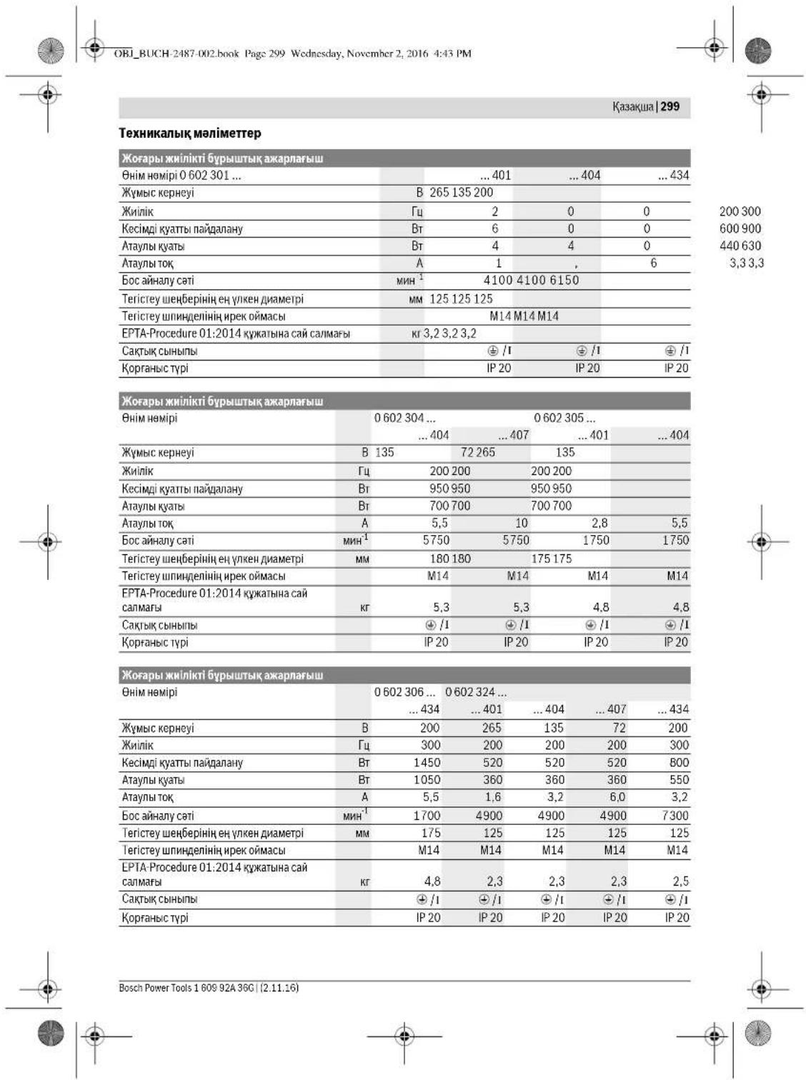
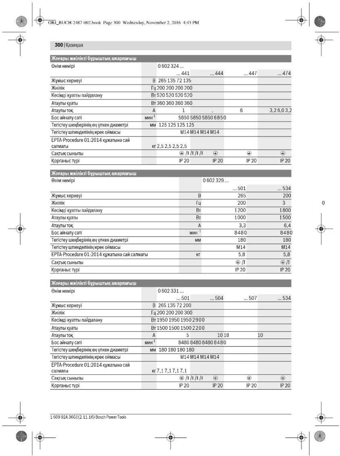
OBI_BUCH-2487-002.book Page 301 Wednesday, November 2, 2016 4:43 PM
Kazakura301
| Жогары жинникovi Бурштейх онлайна | |||||
| Одир | 0 602 332 ... | ||||
| ... 501 | ... 504 | ... 507 | ... 534 | ... 511 | |
| Жу mus керneyi | В 265 135 72 200 72 | ||||
| Жилік | ГИ 200 200 200 300 300 | ||||
| Кесimій куаты пайдану | Вt 1950 1950 1950 2900 2900 | ||||
| Атыны куаты | Вt 1500 1500 1500 2200 2200 | ||||
| Атыны тok | A 5 | 10 18 10 27 | |||
| Бос сөнүлү сati | MH1 | 6600 6600 6600 6600 6600 | |||
| Тerитек ушенийен ec уken даметri | MM 230 230 230 230 230 | ||||
| Тerитек ушенийен иrek ошмсь | M14 M14 M14 M14 M14 | ||||
| EPTA-Procedure 01:2014 куатыни саigмагы | Кr 7,1 7,1 7,1 7,1 | ||||
| СаKitь сынгы | ◎ /I | ◎ /I | ◎ /I | ◎ /I | ◎ /I |
| Коргань с typi | IP 20 | IP 20 | IP 20 | IP 20 | IP 20 |
OBI_BUCH-2487-002.book Page 303 Wednesday, November 2, 2016 4:43 PM

| 0.60232950. | 0.602329534 | 0.6023315.. | 0.6023325.. | |
| a₁ kānilbī Čeρбěny māni (vú 6aβhɪtbiŋBékθoɪpьik Kocbɪnɪdci) jæne K dʌnciádiRiEN 60745-2-3 CTaɪdaptrbɪha cai aɪhɒkɪtərɪŋ. | ||||
| Bettik Āxapnay (ndepeki Āxapnay): | ||||
| a₁ | M/c² | 7 | 7 | 7 |
| K | M/c² | 1,5 | 1,5 | 1,5 |
| Жыntыратy: | ||||
| a₁ | M/c² | - | - | - |
| K | M/c² | - | - | - |
| Aşxpapnay IXcKimen Āxapnay: | ||||
| a₁ | M/c² | - | - | - |
| K | M/c² | - | - | - |
Henk Becker
Executive Vice President
Engineering
Helmut Heinzelmann
Head of Product Certification
PT/ECS

iV. h = m_c
Robert Bosch Power Tools GmbH 70538 Stuttgart, GERMANY Stuttgart, 01.01.2017


OBI_BUCH-2487-002.book Page 304 Wednesday, November 2, 2016 4:43 PM
304|Kasaika
XnHay
KopfahbIw Ka6bIkTapbH opHaty
Xannbi Hcyckaynbiktap
KabknappeTey,6nueKepinAnmaCTbpy
Hemece3eNtKpKaanBhAkbpatyDahAnbH ToTKAH
bifapbH.ObcCaTbIlaPacba3eNtKpKaanBbH
BaikayCbIaKocunByHaKoJ6peMeHd
Eckptne:Kc3HcTeTcrtey H6bepi 63bna
HeMece Kopr4aBn KaTnAa3Nktp KpAa KpBnBnApBn
63bna,3Nktp KpAanBbipDcpeBn Cb3Metine X6bepy
Kepe,MeekHaknapnTyBtBuHaFk3MertKepeTyXeH
naidanany HeKectepI tapayBnH Kapab.
Koparbiu kantamalanabiy uykbladapdbi onepatop xafiba Kapat yuanahtbaid etin opchatbib.
Excerpt: KoprAflbl KantiMaTAbbl KOnlTay
KjduBpUkwnapbl Tek 3nekt KpAnra kapaTbH KoprAflbl
KantiMaTAbbl OPhATybl KantiMaTcAb3 etEdi.
Tericteyre aphanfah Koprafbkantama (A cypetih kapaht)
Tomehderi typep yiwin thicti:
-060230440. -06023295..
-0602324434 -06023315..
-060232444. -06023325..
-0602324464 -06023345..
-0602324474
KoprarbKaTAMAH6apHaiXkayr7emEHH8 Kemerim HnnnDben MOHnHdaFb4OobkkaKoprafHb KaTAMadafbybypTH3eKTPKypandbHpnaHeJine OtbpaHuaOpahtsbH.
Kmbic npocciHtanaTapbHa cai Kopfarbl
KaTamaHbH KyHH CaKaTaHb3.
-Kopfarsbui kantamahbi 6ketyi yuih oraphy BVHTH 7 10HM acnathai aihanyap MyoHemITAP Tahtb3h.
OBI_BUCH-2487-002.book Page 305 Wednesday, November 2, 2016 4:43 PM

Kazakua305
Kaxetertieriteykypanbinydpybcaihany6ahtbna ca11 (terieiteyuehebei,KeceihiTertieyeuhebei,yxnatbte terietyuehebei) terietyuchundenie3opatrBn.
Kbckkuii raiKaHb1 12 kypic npek omacnHa KcbckHui TaKaHbIH optaBk OohfBk KofapbI kaapan TpyatbHdAn OphatbH3.
Kbcknraiknnaiknkiinm 136epik taipbnh3,6yn Ke3ne aibp kinnne 14 tericreynnnnden 3cctan TybpH3.
Wbifapy
Terictey 1nnnndieni 3 aibp kinntn 14 6epik yctan TpybHb.
- KbcKpiMsiRaNkai 12 raima kimTmien 13 bcparan Keqde aibp kimTmien 14 tercetiy uHnHnieni tch an TpybHn3.
- TericyteKpBnA, opiIpeK pAnHeuT tericyte nnHdienHe HbPcb.
3neKtp KypaandapbI uHHndnbI 6yfaray nephecimen5
Tomehderi tynpywn Tmicr:
-060232440
-0602324434
-060232444
lllnnndbuk6yfrataynpne3c56abneneKpypandpa akapnayacnaptanbpohnya cboynbHKinTIPEN TYUkepckbonmduiE1-E2cypertepinKaapanuHa.
HINHnbl6kryTmyMeCIn TEKnnHHnBnE ToKtAtbTuHaN KyIe 6aCbHb3. 8HTnece 3NeKTP KypaBnH 3KbIMdy MYMkh.
-Akpanay KpybIbCbH OPHATyDAN AynBHN WnHnDnBnB 6Byfattay nepHein 5 Akpany wnnHnDnN 3 Byfattay yuH 6Bacun npHeHn Bacun cytHa.
Kepeki xkapay kpaanbH opatbHpaT (TeRicTey wehepi, Kecetin teRywehepi HemeKcynbTH TERTEy whehepi OPAHT.304fertune kapaH)
- 1nnnndbdi6yfaray nephecin5xibepin axapnay nnndenihh6yfaranfahnh aihh3.
Pe3eKTe terictey wen6epnepin MOnTaJkday (FCypetINkapaHbI3)
Tomehderi tynpnyin thicti:
OBI_BUCH-2487-002.book Page 306 Wednesday, November 2, 2016 4:43 PM
306|Kasaika
WBirapy
KatbI kaxtah MATAIbX cbIMb KbiWbAkb19 comBH KINITHEK IAIMAHbIaIaXapnAY IINHIIeIHEN BYpAn AIBH3, OAHc CIsB KINITHEK 14 aXapnAY IINHIIeIHIN H KINT AIAHbIaIaTipen KOHbIaY.
Wanbblxane xokkanapblcopy
KopfaibbOby,keBip aara copTapbi,mHepanap
kahe MeTANIbap bok eBip MATEpamapnBHHa
beCaHcybKaBaHbDbOybl MyMKIn.1WHaFTHKOxHae
haDb KyTu naDaAnHybMa Hemece KaHbNAr
adAaMpaia aaupeHbnk PekuHApnDy HxHe/HMece
TBHHc K0dApbHb AypnpabH TybpbMyMKIn.
KeBip uah Tppnei,acipee emE hOne 1aAMwat
araBbHbUaHb,ecipece,aawtBu Hpey
KaBtuKapBMn (xpomat,arauhPkray a3tu) Bipre
KaHeporeHepEnbbcenETeepi.AScBeTik MATEpHnat
TEKAHMA MANAPMEN OHDenYi kepk.
- Mymkhinuihiniue ocbi matephan yuhiang kienetih uhaocopbHuihui hua danaihhuib3.
KymbocopbHHHkKaCblKeTinyHe Ke3XeTki3iHj3. - P2 cyarti cbihbninbadra rakzaparadpa naidanahy ycbnbnabna.
OeHertenI MATEpHAndpaui Yuii eniJaee KOnJaBnAaHunH YuHaPamDabdi NuaanBanhBn3.
XMybIcOpHbHaIaIaHbIiKHHaYbIb6oBldpMaBa3. 1uaJOhTAYaYbIyMVKH.
3HeprnKoperine Kocbiny
3NeKrp KyaBnH naidany uhy xnniK tyPnehDipriuI Kepek 6oIaIb, on 3paAbykTko3aYtBb TaKtauaqda KepcTeRn HxnniKnE hNIIpeI.
Kmik typeuipriuiy nprii neeeppe, typi Kmiinkepe, ekhiu kepy MeH atayn Kyattapda Bonan. Kmik typeuipriuH Tanyd Kocbaina TuH 3neKp KpaBHa 6baNaHctBu. Kmik typeuipriuH Tanyd yuH Bosch dneephe XabapacbHb3.
3NeKp KpyanBnTepMtnPk npAahb Kaabn btekepcia anac.0h icke koy uih apahb Kaabn bTe TneNtiockc CEE tkepehnn (KaacnTycte) Xabdtay Kepek.
Bdhan baka 3neKtp KpaanbH apTbHKkykTeynd cakay yuii HctaapTb KoarantKmbuTb Kopya eupriimienKa6duKtay MymKIn. OcbI KpOarNTKb Kopya eupriHHH petey aMnArb EeKIP KpaanbHAt aybi ToBbH kAITAYb KEPE (TeXnKbAik, MaIMetep KapaBH). KpOarNTKb Kopya eupriHHbip CekyUHAn TeA cTe nketYl KEPE.
Onuui kozartbki Kopray uipriuHHn naadany HcykaynbHbHdArbKayinciAdik HcckaynapbMen opatny HcyckaynapbOpHdaDa3!
CEE wTekepih ophaty (I1-I2 cypTTEpiH kapaHb3)
- Eki 6ypanahdi 22 60catbn utkepei 21 CEE utkepiHH 24 KopnycbHn HapTbHbHb.
IpnactMaCnBKnKoHbMnBa 25 nEeKtp KpyhntHnHAp ahpai Kaebn DAmtePiKe caKecin CEE UTekek KopynCbH apaHbKaobEnbDtK
Tept raptamblr taipy kuiu H KEMeTIKUHHeN 20 otkiin anapaii
Tept Kuii 6ypanaHua 23 wtekep XHHAHHa 21 6ocatun KOBipL1 TaPAMbHbH YUbIK Xa/actbFbHbH L1 KOHTAKTI YBUBFHa.
Kek L2TapamBbHuytBuKJxanractbpyBbH L2 KoutkAikTyyBbFba
Kapa L3 rapambyh yuhtk knaftactbplihh L3 KOHTAKTIK YUHbHa
Kahe XacblCapa Tama yuhtkbknaftactbplihh
Kopray KAOHTAKTIK YUHbHaCanbH3
Tept kiiui bypaanda 23 utekep xinhaftnda 21 kaiata bypan tor rapambi 6ekirihia.
CocBn 20Tapry KUHIN KEMeTIPIIHN BYTHKABeN KaBEN KabBuHMEnAPaUMyJXKAnfactTpRbTuPaHda TaPny naDa BonMaHTbErin Bypan SeKTHJa.
- WtKeep KxHnBn 21 KaTai CEE WtKeepDd 2KoKpyCbHa bCanb EKI BypaHndAnb 2KaTai Bypaan KoByhBa.
CocbH KpFaybl cbMdbH Aypbic icTeHeHH TeKcepiH3.
- 3Netktp Kypanbiliu CEE utkepei 24 jukilik TynepaBpuiHinich Koc yuyuBhaNanbaCaba.
EduKniNik YpTNepHdRPIiHsAhePnHMeHJkAbdtayKjYekiebc Kocy MMyKH.
XJIKN TYPNEHIDPIIW H3EHPTRHEM JEAbDpKAY KJYecine KOCY KOJIbI XJIKN TYPNEHIDPIIW naJauanay HCYCKAYBnIaJNAKbHaFnA
CocbiHaiHany6afbTbTHTeKcepiH3!
AHHany 6aftbH TeKcepii3
Akapayn annhenniinai aianhy faBtu 3neKtp KpaBtu-ka cbuHnR hKepcTeKIme kai Goybi Kepek.
Erep axapnay uinnenr anraa kicke kocya (0nektp KpybnbKocy/oipy 3076eirnde kapaan)kare 5aBrtta aHnAna cnektp KpybnbDpeey kaiu euiipin 3neprn xnenicihen Aekipatyekek.
Ei- Ekpabdahb 22 Kahto6ocattn Tekepej 21 CEE Tekeepihh 204 npocnhyhKahta Tapttn aBbHba.
-KohbpKaHeKapaTapaMpaDpBbHyUbHK KaHaTractbPbBtPaBbH KOHTAKTTKyaBbKTabpbHaH BocatbBb3.
-CocbH Kapa L3 tapaMbHbH bYtBbK, XnafactbTbpfbluH L1 KOHTAKTTIK YRbHbTaXHaHe KOthpL L1 tapaMbHbH bYtBbK XnafactbTbpfbluH L3 KOHTAKTTIK YRbHbTaXHaHe CaIbHbB.
- Kiui Byapanadpanb 23 uTekep XHHaBlya 21 Kaia Byapan Taepamda BekiHua.
- UTekejKeiNaHbIn 21 KajraCEE UtekejDin 24 KopnycbHa bcan bEn k6 BypaJdAnu22 Kajra BpaJr KaobHb3.
-CocbH Kopraybiu CbIMdbiD ypbic icTeReHH TeKcepiH3.
-3nektp KypanbH KaTaNepnR HcnicHeKocbHb3.
Paiandaanhy
Tnndanahyfa eHdipy
ToKKe3iHn KKeHyIeMH cactoTaBcI AnekTp KypanbHbH 3aytItbTK TaTacblAarDepekTepe ca8 bony Kepek.
PaiDaananyan anbHn axapnay kypanapbn KaTat Keceprih. Axapny kynpBbeip opahbInu, eWKepecria hanyana Kkert. 1 MHyrt opHne CbHAY KyyMcsbn KxyKtemec3 opHnHdz. Akaybi 6ap,
160992A36G|(2.11.16) Bosch Power Tools


OBI_BUCH-2487-002.book Page 307 Wednesday, November 2, 2016 4:43 PM
Kazakua307
domanakemecexhe dipinieitih akapnay Kypanapbhi nainananabhcbby. ByunrA hakapny Kypanapbhi kapsbn 3akdpara anyn kenyi Mmki
Kocbhu/ewipriuri1 "owik" Kyinhe,3neKtp KpypanbkytinmerenHeckbhu/ewipriu "kocynb" Kyinhe60bndaToKaTARAna anapbHs.ObnblnBakunaycbKaHtKaocbnydlnanbDnAnhAnacb3.3neKtp KpypanbKocdyanAanb(3HeprnKoperiKocbny 306 BcIneKapaba)3HeprnKaJbIbKanByTeKecpDin
普 品 品 品 品 品 品 品 品 品 品 品 品 品 品 品 品 品 品 品 品 晶
3EnerpRA KytaBHy YHemeDey YuHIn 3eKtp KypaIbN TEK pndaIaHaDpaKocBbHa.
Khinik typenhdpriihiin Kockbiw/ewipriwi
Alybembe zhuiik typehuiipiiuin icke Kocbi, cocbi h 3ieKtp Kcpalbn kocy kepek.
OnyuiiXinH TypEnDprHInnNaiDaNAnHy HcckayBaHn eckpnHa.
3nKtp Kpyaln Kocy/Euipy Kayincidak Jxkblbma eoiipri (J1 Cyperin Kaapanba)
Tomehderi typep yuin Tmici:
-06023244
-3nEkpKpAaBbKocyuHIN KockbUeipriu1 1 anfa baccbHa.
- Kockshu/ewiPripril 1 ophaty yuH kockshu/eiwipripril 1 aBnIe Tbe TereTneHue bacBaHs.
-3nckrKpybnH eupiy yuiH Kcoku/epuipriurixieepi31.
Bekirinr Kockkii/Heiipriuie 1 OthApkaTe TemeHre KaKcBaCin coBchJxibep3h.
3nEkrKypablnkocy/Epsiy KanyinlaikdKokbukbimen (J2 cyptin Kaopba)
TeMeHederi typepyuih thicri:
-06023014. -06023295.
-060230440. -06023315..
-060230540. -06023325..
-0602306434 -06023345.
-3Nektp KpyalnKocy yuHcnnPiU1 1 anfa XbJIKBtBhBa,COJAH KeHH BaCbHaB.
- BaccnHae Cenepriu1 6ekiry yuin cenepriu1 r 1 oan apnfa kXkNkBtBnHb.
-3nekt kypandh eulpy yuH cenPiuri 1 KibepiHa Hemeke6kntine, cenPiuri 1 Kkka yaKbToBoH bacbuaJxHeXieBepiHa.
PaindanahyHycKaynapbi
Xa6bikTapbi peTey, 6nweKTePIH anMaCTbpy Hmece3neKTP KpAbn AakBpaTAYanAnBbTHoTKaH bIbapbHb.0Cb cakTkI Iapacu3neKTP KpAbnBbIH baiKaayc3h KcOJIbHaHkaON KePMeHJ.
TepKa KaBbIpaNaDa aoiBbIkapacHaHgdaaBaihBa3, CTeRnKa TuypaNbHcKyaNapTapayBH KapaHb3.
CamarbaI typakI kaihItbI kAmamac3bnEtnec, dabHdamaHb6KtIi.
3NeKtp KypanFa ToKtaFahwa XyKTeMe TycipMej3.
XoRaHpIyKXTMeDenEeKeIN3NkTeP KxprAnDhBipA3 cankHnDaYbHa, BiPeHee MmYHT60cXvpiTe cXyMBC ictyeHIO MymKInDk Epin3.
Kennyiu Taipid terictey wehepimen terictey
Xnnnyiupaipdi terieey uenbepimeh (kypan)cohmeh bipre Dooec bertepdi kane npocnblpepi deohyre 6oana.
Xennyiu Taipid tericrey wengbepnepi aedter terictey wengbepeimem caihctbipraa y3aibpak Kb3me t etdi, asbpa.uy shu npapda knothe terictey temnepatypacbaasbpak bocanpa.
Metanapabibkecy (Kcypetih Kapaiba)
Baanahbctb6pa3nBtepKemirimHen Kcye yuih apkaaah KcyeapHanf KanTamahb nanaanahbH3.
TericTey weHbepimEn KcKcKeHe bipkEnki, MaepHan yuHIN
IpyHCbBepmEn YXMBIC tctHJI. KecyweHbepHe KpbCM
TycipMeH3, OHJ EeKHeTneHJ XHe WaiKaMaHbI3.
ByipnIK kbcMbme HAnrAraHbHa KeCy wHbepiN
TKotarnAbH3.
3nKpKpIaBpApaKaauHAnanyBaFbTaHaKepiXpyri3y KepeK. 0IeNne6KaIbayCb3 KecinreJkePeHbUry Kayni TbyIaIaNJI.
PnDHHJIeHJI He MeceTe KpHJIy KxSyBapnJIky KeCy KEiJIeKcEuy JEA3KaJIqHeEH KHMJAaBaIbAHJ.
Tactbi kecy
Tacta KekceKekHe MaHbH,KeTkinlIcI copblyH KAMTAMacb3 etH3.
WahyTkbiuMackacbHknH3.
Byn nneptkr Kpyanr bTek KpyraKcey/KpyrK teriTeey yuui naihanayna 60anai.
Tactb Kecy yuH anMac Kecy dckinepin nahdanaHan KeH.
Thekepinyen Kaylinciadkti KAMTamachs ety uYHH
BafttaBHTaHPb Bap Kecyr apHaFAn HbFapHb
Kanamahb naananye KepK.
3nKtp KyabHIn KtsuaHcoPbUuHne NaidaHaBnKocBmuA nepcnHapuKiiHia
LhOcPbHHTaTac 1sHbHnCpOrya rPyKcT aBonyu bKepek. Bosch ocb.bndai HauocPbHtuaTadby cYbnaHd.
-3nektp kypandb bomega h3 kane 6bafttaybiutapabH b a/bhBb101mEH bennueke opnhbHb3.3nepK pynandb bipkkeni, MaepnAnFa caikec 6bpymen KblkbTbHb3.
Kypamblda Knbiipbuk Tac tbe ken acakatbl
Maepeanapdui, Mucanbl, behotdy, eueyKeiainam
wehdep kbl3bn Kery hi Xaepanbl yMmKIn. Anmac
wchdeperr YuKhbpadopocBnbl BnDipc.
ByxJafndaa Knymbctbl ToKtAtbHbXkHe anmAc Whebp
60cKxypIte, hKorapbl KjUdpambkTa KbckaYakB BoHb
CanknOdbHbHb3.
OhiminiHnattapnbkTnTemmepeyixKHeYuKhBnDapnAmC Keeyueepi etnc Bonun kanaRbn BnDipepi. OHb abpaaNtMatePnAnda, Mucbnai, CNHKat KipniTte, Kckkaasa kecyapknblb tkiipinye boanla.
Bosch Power Tools 1609 92A 36C (2.11.16)


OBI_BUCH-2487-002.book Page 308 Wednesday, November 2, 2016 4:43 PM
308|Kasaika
CTaTnKa TpyaBb HycKaynap
TipeKabbprranapdarboBtaptaraDN 1053HopmacbHbN 1 TaMPaHHeMeCE caKeE cnerepex KpndAHOJIb. BynYcaynapbMlIeTIyTpTe npOuaypeKxKMybCTb6Bactam6byhIN CTatnaXxHdERi MAMAHmE, CaynTeWIMHEmeCnpopabneKeeciciJ3.
CbDybipIn tericTey
EkuKaan Keey Wne6bepnepi CbIbpynn Terictey yuHn naJaanAnaabHs.
30^ - 40^ wenbep dypbmbimc hcbipbn terictey KeiHne enkcbh HtHnepn npyfa6oanbl.3Nektp Kpansbl kainan bacin, anra kane aprtka kblnnbtsb3.5ynKeane daibdaamtbimkatbkbasdytcin eaeptneidjxhe aphanap naia dbommaib.
Ereykymkarasbimen terictey
KoNaJIbI teriTeTey KaFABH TaiJaye EUYe Kepek MaTeHnFA 6baHnBuTc.
Bosch pesenke teritcje ueh6epine XapaiuH, canabAp typi teritcye kara3ytnepin ycbna. Mamahann Keheac abiYbM3.
Matanbik kbltbpaty dnckicimeh kbltbpatbhi3
Kbntbtpaty KeaHJeEeHEnTin MaTePhnFA HEmec MAtanBk KbIbtpatry DcNcICHe AkpnaH aTaTterH cyPnin AinHany apKnH MaTePhnA bteH cHcH.
Erep bipheue xbltbpaty 6ackhura xymbic ictecehi xahe Xbltbpaty aatteri Mndapak tyipkepccte ap Xbltbpaty aatteri tyipuiktopi yiwih 6oek matahby ankyepek.
XbIbIpyaBckIbIaBbHApacbHdaeHdEnerIH MaTePnAnDbetIN abEn Ta3anAb3.
TexHHKanbIK KYTIM XaHe Kb13MeT
Kb13MET KOpCety KOHe Ta3aay
KabikappeTey,benwekeptipnAmactby
Heme3ne3ktp KpAanBxkpatyDAnbH ToTah
hBapbHLb.ObcakTbIpaac3ne3ktp KpAanbH
baKaayCysKocuunHaJN konEepMeidl.
MybcxJhe cemimciTeiy uhy 3nKtpr Kypamme Heketki tckrti taa YctbHa.
ToteHwe kymbc XaFdaBnHa MyMki 60nFaHua
XaCnpBtBuNbnaDAnBaHbI.KeNdeKtiu Tcckti
Xynypen, Ta3aptbn aptbTKOTkAnCaTbHn
KocBtu (PRCD) KocBtu3.MeTaNbE HDeyede ToK
EtK3iTeTH uH eNktp KpAanBHH iHiiHJe KHeHanyB
MyMKH. 3eKnTp KpAanBHH OKwayNaBHu 3aKmDnanyB
MYMKH.
Akapnay uHHenH6oc aHany Moentin Hxyeni Tpyde enuH3.Erep anuHreM Me6epinre 6oc Ypicta anhmbnpcaHbHb10 NkemTHeMece Xoapb6oCana("TexHxaKbnMOnimetTeP"kapaH3), 3eKtp KypabHosBckmETKepecyotptanbIbHa TaKepey KeK. Xoapb6oc aHany MoentinJe amAhna-cannMbacnAn cHbYbMyMKIN, TeMH aHnhmbmpcHbHaJxMYbcKbYbMeHedJI.
TeKaHaTynckanbKa6enblnaiDanaHbHb3! 0epipnndaanhyd anhbn HneKp Kyaanb, KaBkdiHHeAihbpDnAkhMdyAnpyra TeKepeH3. KaebmEH Wtkepei XeHJeyMyMKHcE McayInTeepH anDbHany yWuH onapdp anlmactby kaxet.
Kb3METKepeTyXaneXeHDeyXMybCTapBnTEK MAMAHdAPMeNdaBbHbBfBbBapK3METKeepep opbndacBc. Can apkblbnJekrKpaybnBhB kayincdiHcakTcb3.
ToTahAnKApBTHaH3NkTpKpApaBbHINKcOyYuBbKTapBH, TIPKeiCIMepHJxHeIteKeDJI KpKr, TYKcIyWbpeKeHN cyptin 1nHmNac BSeWkeTePHIn anTactaHb.
BipHui 150 naananyCaratbHaH coh Bepicn KopabHn XePiKtien TaanAbH. EpiKiH OHdpUwHIN naananyXeKaTeE Xapaty HcyKanBtAPBH opbHdHb. Bepicn KopabHn apAhB Bosch CepakopabHn MaHmH MaHn b. BipHui Taanayda hactan Taanayadici n 300 naanany CaratbHaH coh KaTanaHb.
ThetaBosch cepBtckr optaBf ydn kymuctapdb JxMaAM XeHMe DPeTT OepbHdHb.
Erep6aihnaibc cibmbln anlmactbpy kakket bocca, kayinicdikintiH tomehdeiyhe xon 6epmec yuiin amactbpytbk EOS Bosch Hemece Bosch 3neKtp KypanndpaBHH ABTOPIAaIIAHraH KNHETpe RkMet Kepcety optalkaptapdaOpHDAH.
KabHKTapbl MyKHTcaTahIsKaHe KyTHI3.
KepeK-kaPakTap
TolukcananJkaobknapaBapnmaTypanb
InhertteWww.bosch.pt.com He
www.boschproductiontools.com MOKHKaiHHaHEMeOe
MaHaHaHaHaDyKekHj3eMJIiMetAlyMYMKH.
TybHybIra Kbi3MeT KOpCety XaHe naDanahy Kehectepi
KbMert Kepecy 7ueBepxAnahcbl BHIIMJKeHcyJeOHe KytY, COHNaIak Kockanb6enBnEeKTeP Tpyanb cypaTapra Jyayan bepei. Kaeketti b3b5anaf Me Hockanb6oNleEeKTeP typanb I apakattnb MblaMa HekeKaHaidan Tabac3s. www.bosch-pt.com
Kehec 6epuyi Bosch kzmertkepeipimai naidananykane onapabn kocankb bnoekrepi tpanby cypkapbrbtra THHAKTb kayan bepei.
CypakapKIOXHKe Hcokanb6benuekepre Tancbpic6epy KcHKeIeMHTeIpye OHmIH3ayBtIKaTakHaacbHArb10-cabblbHemHemPiHxKaHbI3.
Hdipyui TaniTapbi MeH HopManapbHb CaTanyBme
3neKTP KpabHb KHeJeY KeNlDj K3Mert Kcpctcy
6apBik MMeNkETep aMyBaHaTe Kopept BoW
fPHMaBik HMeCEA bApTO3aUHnFAHn Ka3Mert Kcpctcy
opTaNkTAPbHaOpbHaJanaH.
ECKETPY!3aHcB3KoJHMeHekiHHeHhIMdeppi nAananyay
KayIni, DeCeHAYbIFbIe3AeHHKeNTIPyIyMMKIN, OHmDEpDI
3aHcB3KACAYKHeTAPAty AkiMImIKKaJIeKbIIMCbTbIK
Taptin BoBHua 3aHMeY KyaANAHAdi.


310 Romana
Pomirea/oprine sculei electric
cu intrerupator de siguranta (vezi figura J2)
Valabilepouru urmatoareletipuri:
-06023014.. -06023295..
-060230440. -06023315..
-060230540. -06023325..
-0602306434 -06023345.
OBI_BUCH-2487-002.book Page 324 Wednesday, November 2, 2016 4:43 PM
324|Быларскn
Echipa de consultanta Bosch va raspunde cu piacere la intre bari privind produsele noastre si accesoriile acestora.
Ic zae de reclamationi s comenzi de piese de schimb va rugam s indicai neaparat numarul del identificare compus din
Tel. service scule electrice: (021) 4057540
Fax: (021) 4057566
E-Mail: infoBSC@ro.bosch.com
Tel. consultanta clienti: (021) 4057500
Fax: (021) 2331313
E-Mail: infoBSC@ro.bosch.com
www.bosch-romania.ro
Eliminare
Sculele electrice, accesorile si ambalajele trebuie directionate catre o statie de revalorificare ecologica.
Nu aruncatisculele electrice in gunoiul menajer!
Be3oNaeH NaMH Ha pa6Ota
BTeKHeHTPnHn,CteTe BmMaTeHo DeCTBHnCa n HOBtnepeNa3NBO pA3yMHO.HeHnON3BaIe neEKeHnCTpyMeHTA,KORaTOcYE mOpoeHHnNOd BnHHMeToHa NaKoTHuHHeBeCeTbA,AnkOxnn HnyoBauaNe NKepTaBz.EiMHrPaCEHOCT npHpaOta C eNEHnCTpyMeHT MoKe Da HMA 3a NoCNECTBNE KINIOHNTO EKKN HApABHHBA.
Pabotete cnpedna3aao pa6toHO 6neKnHO BnHARc npedna3n OHua. Hoceto HA NODxOuHa 3nONBaB HNE ENE KTOPOHTyPMENT H 3b5pBbaHATA DEHOC NTHN Hnpedna3H CpeCTBA, KATO DAXTeHMA MACKA, 3p4ABN NTHO3ATBOEPHI OBYKIN CSc Tc6NIHrpaHep, 3aunIT HA KAKA INI YM03aRnyUHTEN (ANTKPOH), HAMANRA PCKA ONI B5HHKBAHE AYTPODA 310NYQKA
H36rBaHTeOnaHocCTTaOtBKnIOBaHeHaeneKTPoHHCTpyMeHTaHOHeHNMaHHe.IpeDN Da BKnOHTe eH
1609 92A 36G| (2.11.16) Bosch Power Tools


Bmrapckn|325
cenaB3axpaHbAaTApexKaHH daNoctABHe AkyMnyatopnHata BatePna,Ce yebpaae,ye NcckOBnI npkcbay eNnoKeHene,3KIOUeHO. Ako, KOATO HOCHTe ENEKTOHNCHPTyMeHA, DpXKHe PnCTCb CH bPxY NcCKOBH INPKCBaH,NH AKO NOdaBATE 3xpaHbAHO Ha InpkeHHe H AEENKPOHNCHPTyMeHA,Koato E BIKIOHe, CbueCTOBya ONACHOt OB3HKnBaHa He TpyDOba 3nIOI Nyka.
PnDn da BkNIOHTe ENEKTPONHCTpyMeTHa, ce yBepaBte, che TcE TcTpaHNH OT HrOER BCNUKN NOMOUNH NCTpyMeHTn rAeHN KNIQOBE. NMOUEN HINCTpyMeHT, 3abpaBCH Ha BbPTNtO CE 3BcHO, MOKe Da pNpHNNI TpaBMN.
H36aBaIe HeecCTBeHNHe NOnOKeHHHa TAnOTo. PAbotete BCTBnHO NOnOKeHHe HAI TANOTO HBB CKEKMOENTNODbPbXaJIePAbHOBcEe. TAKA IJIe MOKeTe DA KOHTponIPate ENekTPOHNCTpymHe Na-Dope H No-630ancho, Ako Bb3HNHe Heo4aBHcTaYCaJyAa.
Pabotete cnoxoadnio obnexno. Hae pabotete c hipokn dpxenHnIykaepnEn. DpbkTe Kocata cn, dpexte nBpKaBaHnHaBezoNchoPa3oTOnHeO tBpytAnCse 3BENA hneKToPHCNCTpyMeHTne. HIpokkTe dpxenY, ykapeeHHNTA, BInTHe NKCHMOrat da 6bDat 3axBaHAtn YB-LECHNOTBPTUIN Cc 3BENA.
AkoeBb3MOXHOH3NO3BaHEoHa BbHHaACnHPa- OHONHCHCTEMA,CeYBEPBAAITE,CETREBKNIOOHA H cyHKUOHHPaH3NPABHO.HNIO3BaHEoHa acnHPa- OHINHO CHCTEMAHAMJNAHPCKOBETe,BbNkauHcHaOT- Denaata C npn pabota npax.
PmKnB0 OTHoWeHHe KbMeNEkTPOHcTppyMeHTte
He npetobapbaite enektonpHcTpyMeTA. Hnnon3aBte enektonpHcTpyMeTHIe cmoCb6pa3HO TAXHOTOPnpdHa3aHuHne. Upe paoitne no-do6pe Hno-6e3onacHO, KATO hNn30BaTE NOxOuHInE ENKTOPOPHCTyMeHTB 3aDAnepHOT O PNOAIBOTIN DHAaON HA ToHOBAPBaHie.
He HanaBaiTe IeneKToPHoHCTPyMeHT, YIHTO NcKOBn PneKbCBAe U nobpeH. ENEKTOPHHCTpyMeHT, KOHTO He MOKeJa 6bJc 3KJIIOHBAH BIKNIOVAH No pRzDIBENHOT PnO3BaOITENAHuHn, eOnaceHN Tp86BaJa bJbepeMOHTHaH.
Pepn da npomeHte Hactpokhte Ha eKtpoHcHpy MeHTa,da 3amEHHe TaobTHN HCPTpymH N Ombnn HENn pncocObeHN,KAKO h KOrA TpoDbNkHtENHO BpeMe Hama Da KnoIb3Be AeketpOKHCTPmHaTa, HKnOyBaHte Wencena To 3axpaHbaaata Mpeka HNNKnBxKaTHe AkyMnatOPHata BatePHa. Ta3i MprKa npemaxBaOnaChctTATo 3aedHCTBaHe Ha eKtpoHcHPTpymHaTo NEBHHMaHne
OpaHbAaTE eNkTPOHCTPymHTHe HaMeTa, KbTeo He MoTAt Da bDaat DOCTHnTH OHe Ta. He DonyKaTe Tte Da bDaat KAnON3BaHOn OT Nua, KOHO He ca 3aNo3HaTH C HauHa HA paBota cTrx Hc He Ca npOeynTe3nHcPTPyKuHN. Korato Ca B pUeTe Ha HEONIHIN Notpe6HtEN, eNkTPOHCTPymHTe MoTAt Da bDaat H3KnIOHTHO ONaCHn.
PnDpKxayteeneKTOPNCHTPEMHTNCTe nRPHKHO. PnpOBpaBtAa dAno nnbHKmTHBe zhae aFykuHouH
pat6e3ykopno,daHn He 3aKnHbAT,daHn HMa cuyneHH nnNBopeDHN DetnHn, KOnO hApuBaHnat HnN Me3HeFHyKNUHTHe NaEKeTPOHnCTPymHe. IpeJa Da nON3BATE eNeKTPOHnCTpyMeHa, ce NOrpHexe noBpeDHN DetnHn da 6bDat peMOTHpAHm. MHoro OT TPdyOBITE 3IIOIOniKc Ce bJbXat Ha HeOpbe npOdbpaJbn HNEKETPOHnCTPYMeHHuYIpOe.
PnDpBpaHtepeKHeHTeHCTpyMeHHBnHArHdo6pe 3aOteHNuCHTN.Do6peNoIb-pKaHnTepeKeueHnHCTpyMeTHnCocTPhpb6BeOBKaABTaNoMaNKcBnPoT MNBHeHEceBOEOTnNoNEKO.
H3non3BaIte enektpoHCTpymEHNTe,doBnHteneHHTe pncnoCobennH,poBHTNEHCPTyEmTHN H. cbo6pa3Ho HcTpyKUHHe Na pOa3BDoHTe. Pn ToBaCe cb6pa3BaHTe N C KOHNpEHTHe POaBOH YcNOBn H OpeaunH, KOnTO TpRb6a Da H3bHInHe. HnON3BAHETo HA eEKeTPOHCHTPyEMTH 3a pa3nnHn OH npDeBnDEHTE O nP0B3DoHTe pnpIoKHeH NOBnBa BAnOACCHOT B3BHKNBAAbe H TpYOBn 3IOIOJyHK.
PnDabpxane
Donyckahtpe pemohbHa enektpnHcTpyMeHTHe Bn ce H3bpuBa cAmo OT kBNHmHpaHn CneuHnCTn cMoC hKNOBAnHo APmHnAHnPe3epBnuaCTn POTo3 HAuHcCe rapAHTNa cXpaHnBAhe Ha6e3onacHOCTHa enektpnHcTpyMeHa.
Yka3aHn 3a6e3oNa cpa6ota c brrnoanf H O6uH yka3aHn 3a6e3oNaCHOCT npH uHFOBaHe CkKp Ka nnonpHaene
Othac ce 3a cneHnTe Moen:
-06023014..
-060230540
-0602306434
-060232440
To3n eNeKrPoHcTpyMeHT MoKeJa cHaON3Ba 3a 1nnHOBoAe C Kypka H3a nonHape. CnBa3Bte BChuKy Kya3AHn N npEpyPckEnHcy,cbOp63BaHte Ce c PnBHeDeHTe TEXHueckn NapAmETn H3o6paHte Ako He cnaBate CneHTE Yk3aHHa, nocNedCTbHATA MOrAT Da bDaT TokOB ydap, NoXap H/IN TeKKn TOABHH.
To3n enektoponhctpyment He e noNxoJau 3a uHnfoBane, p60ta cTeneHHyETKN H6pa3nHO p3aHe. N- BbPbBAHETO HaJeHIOCTM, 3a KOHTO enekTOPOHCTpymEHbTHe eIpeHa3AHueH, MOKeJa bEe OINACHO JaDObede DoTAPBM.
O6uYk3a4Hn3A 3e03aNoCHOT PNI HmNΦoBaHe,pa60Ta CteHNOHTK N6aB3HbNO pR3aHe
Othac ce 3a cneHnTe Moen:
-060230440
-060232444..464.474.434
-06023295..
-06023315..
-06023325..
-06023345
TOnE enekpToHcPTyMEn MOKe da c3N03Ba 3a 7nnHbOaBe, paboTa c TeneHH eTuHK h a6pa3BnHb P


OBI_BUCH-2487-002.book Page 326 Wednesday, November 2, 2016 4:43 PM
326|Былгарскn
3aHe.Cn3BaHtE BChKKn Yka3aHaHn npDeynpExe Hn, CbOpa3BaHtBe Ce cPnBHeDHeTe XKHeCN nApamETPH N3o6BaJehn. Ako He cna3BaTe CnIeHNTE yka3aHaN, NocneCTBnTA MOrat Da bOdai TOKOB yadap, noXkap H/nn TeKKn TpBmN.
To3nEneKTPoHHCTpymHtHe nOxOxJMy 3a 8nnHOBae C uokpyka N a nonpHae. N8bPbBaHETO Ha deJeHOCTH, 3a KOHTO EneKTPoHHCTpymHcTb He c PnCnHa3AHyM, MOKe JIa bJe OAnCHO HJa OBeJe JO TpABM.
06u yka3aHmHa 3a 6e3oNaH aPobTa npn uHFOBaHe c HCK n uKpyKa, NoCHCTBaHe cTeIena YETKa, NoHpaHe p3aHe c a6p3HBeH dck BAnHNo 3a BcUKN MDoJIe
He KAnon3aIe DomnHnHTENINPnHCNO6NEHN, KOHTo He CE npenOpBvATOTnpON3BOITENIE CNEHAN HO 3aTO3 ENEKTPOHNCTPMYENT. QaKbTt, cHcMOKeTe Da 3akpenITE KMa MaunHATA ONpeDEnHO pncnOC6NEHn HN paBOTEN HNCTPymET, He rapaHTIPA 6eOtonACA paBoTA C Hero.
DonyctHMATA CKOcPtHa BbPteHe Ha pa60THHn HcTPMENT Tp6Ba Da e HauMaNKO To PAba HA3nHcHcHata HA Tabenkata Ha enekTPOHcTpyMeTA MAKCHMAH cOKoCTHa BbPteHe. PaoHTHnCtpyMeHH, KOHTo Ce BbPTAT C NO-BHCOKA CKoPcOT OT DoryCTHMATA, MOIa Da CE CyHrN I NapeTa OT Xh Da O1XbPcHcBNCOKA CKoPcT.
BbHnHrT dAmetb np He6eBnHnata Ha paOthn HNCTpymEnT 1raBa c bOteBTat Ha daHHne, NocoueHNbTexHeWHeCKeKTE XapKeTepCHNKHa BaauHn enEkpOtnHcPymEn Tc HENOpTcHmNc HENOpTcHmNp a3MepeHn HeMoraTda bEaTeKpAnHpaNIO HeoEckOxMMHauHNn HINn Da bDaT KOnTHPOpanHn DocTa7uHO doBe.
PaobTHH HCTpymEnH c onaNka Ha pe36a TpRb6a da NacBAT TOHO HA nPcBcEHNHnHTApe36aBa Hana BA mAHnHATA. PnP aobTHH HCTpymEnH, KONTO CE MOTHPAT c NOMOHTA Ha fAnHeu, DNAMetbPTbT Ha OTbopa TpRb6a DA nACBA TOHO HA dmAmeTpba HA pNcEeHNH TENTHO CTbNA HO fAnHeu. PaobTHH HCTpymEnH, KONTO HE bDt 3axBAHAt INPABINHO KSM eNEKTPOHCTpyMeHTA, CE BpTt HEPABHOMePHo, BHbIPnat CNIHO MoTat Da InpdN3BHKAT 3ary6a Ha KONTpONd eNEKTPOHCTpyMeHTA.
He h3non3baIte NOBpeHn pa60TH HnCTpyMeHTn.
PiEHN 8NcKHa NytOpe6a noPbePABEa HnTOBHTHE nCPTPYMeHTn, HnIP, a6pAHHNTHE nDCKOBE 3a NyKHATNN HnOtKbPTEHn Pb6eta, NoDIOXHHTE nDCKOBE 3a NyKHATNN HnCNHO K3HOBAe, TENEHIE YETKN 3a Heo6pe 3axBaHn Hm CuyEnHn TenCeA. Ako N3TpBeTe eNEKPOHCTPYMeHTa MNo PAOTBHn HnCPTPYMeHTn, n PnoBepBaIte BHMaTeHNO 3a yBPEJDAHn Hn H3-
ON3BaIte HOB NnoBpeHn PAOTBHn HnCPTPYMeHTn. CneI KATO cTe npOBepHN BHHMaTeHNO H cTe MoTHnpA
nn Pa60THHn HnCTpyMeTn, OCTabe ENEKPOHCTpy
MEHTa Dpa POBHTNa MAKCMMAH N oOBOPTn BpoDII
KeHHe Ha eHa MHyTA; CToe N dPbXte HAmpa CE
HabNIIN NHA BCTPAHOn pOABHHATA HaBPTEHe
HaueoTocnoepednabpoHNTNHCPTPmEnCTeYIPTnp30nTTOCTpNOHnO.
Pabotete c HnH npEa3n CpeCTBa. B 3ABHCMOCTO pnploKHeHTo pabotete c qnaMaCKa 3a NHe, 3a- nHTA 3a OHTe HnN pnpa3nH OHNA. Ako e Heo6Xodmo, Pabotete c HxATKeNa MACKa, UyMo3aRyUHHTEN (ANTFOHH), paoTH OHbIKMnCneuHaHnHPaHn pceTnHa, KOTB To NPepa3BaO tMANK OTbKpTeHN npPabotata TAcTHKn. OOHTe BNrPB8a ca 3auuTeHN oTNEIHTe B 3OHaT h aPbota TAcTHKn. PpOtnBOpaxOBATA HnN dHXteNtHa MACKa FInTPnPAT B3HNNKBA uHn npPabotata npax. Ako npDjBxHHTHO BPMe CTE HIOKENH HcINH Wm, TOBA MOKe da DObede Do 3aYbSA hCJyX.
BHHMABaIte ppyHnHa da bIaT ha 6e3oNacho pa3- cTOnHMe OTOHATA naPabota. BceKn, KOHO CE HAMPA b3OHa nPaobTa, TpBaBA Da HOCH NmNHPnpeNa3H cpECTBa. OTKbPTHe NaepuHcA To o6paOBtBaHN DetAnn NnPAoBHTHN HcTpMeHT MOrat P be3yNTAT HA CINHOTO yCKOpEHNE DA OTIEIT RaHdAue He Ia IpeK3BMkAT hapAHBaHNA BcuH IOA3bHbONHATA naPabota.
Korato cIbIeCTByBa onaHcO7 pa60THHT HcTPyMeH Tda nonaHdHe h a CKPHn NO nOBbXpHOCTTa pNOBODHIN NOI HANPEKHEH, dPbXte ENeTPOHCTpyMeHtCa MDo 3a eNETPOHON3OHPAHETPBkOxBATKn. Ipn KOtAKT C npoBDOHNIO NpHANPEKHEH To MOKe JAc ce npedJe Ha MeTaNHHe eEMeHTHa EneKTOHCTpyMeHtHa TOBaJa PnDnBbKA TOKOB YAD.
Ipbxte 3axpnaa K6en Ha 6e0nacno pa3cto Hne O BPTAHTCe pa60THN HCTpyMeH.N AKO Hcy6 HcTPOH NAEENKTOHCTpyMeHra, Ka6bTe MoKeJa da 6bepeepaa HmYNEueHOT Pa60THN HCTpyMeH IN TOBA Da npedhBkHa PahnBaHH, Hnp. Ha pKaTbA Bn.
Hkora He octabite enektpoHHCTpyMeHTa, npen pa 60bHTH HKTPTyMEHT Da cnpe HanbHIO BpTHeTO CH. BpTaHnI Ce HcTpyMeHT Moke da dOnpe Do npTeM, B peyntat Ha KoToE da 3aYb6te KOtPOn Hd enektpoHH CTpyMeHTa.
Dokato npenacate enektpoHHcypmte, He ro octa BkHIOHep. Pn HEBONEN DNONHP dKpEXHE MHN KCOHe BnMOTa 6b4at yBneEHN OT paOHTIH NHCPTPMHT, Bpeynta HA KOETo PAoTHHAT NHCPTPMHT MOKE Da CE BPCKe B TANIO Bu.
PeoBHOIOuOHCTBaIe BENTHauHOHHHTeOTBOPn HA BaHnHa eNEKTOHPcTHpyTMeH. Typ6HnHa HApEeKTOpBNaTePAH3AocMykBA npax B KopnyCa, aHaTpyBaHeTo Ha MeTANH pIepyBENHaa OAnaOCHCTTa TO KOBbYupd.
He Hanaabai Te EneKPOHCTPymeta B 6n30ctdo NecchoanapanamMATEPHAN. IeTAAU NCKPH MOra Dja PpD13BHKBt B3nnAmeHbAHETO H TAKBA MATEPHAN.
HeHsnon3BaTe pa60TH HnCpymENT, KOHO hKcBt pnnrAraHTo Ho xNaxKaau TceHoCT. HnoIeBa He HO BA JIN npyHn OXnJaaiu TeHocHT MoKe Ja PnpE3BHK TOKOB YdAp.
OTkar CbBETHaH36RABaHToMy
出 Otkare BHeaHnHa peakua Ha MaaiHnHa BCnepCTBHe Ha 3aikHHBaHe Hm N6KnKpHa He bBpTnca Cp aBoTeTH Hc TpyMeHT, Hapr. abpaBaeHN DnCK, yEme NoJIOKeH DnCK, TEHeA Tetka H np. 3aikHHBaHTo Hm N6KnKpHaTo BO


BbIaPcKn 327
HndoPRAKOTCnHPaHa HbBpTeHOHa paOBoTHNHHCTPYMHTB.CBJeCTBHe HA TOBa ENeKPTPOHcTpyMEnbTIOyUaba CnHnO yCKOpEHMe B NocKa,OBpaTHa Ha NocOKaTaHA DBHKHeHa HnCHTpMeHa BTOKaHa B6nOKpHa,NECTBAeHypnabRe.
Ako Hap. abp3AHBn DnCK ce 3aKHHHn Hn BnOKNHp a Ob pabTBAHOH N3dneH, Pb6bHa nckca, KOHONPJeTaHnA MoJc Da CeOrHe N BpeyntaN DnCKbJaCe CynHn NN da B3HHNKHe OKrT. B TaBk Cnyh A NkCtB Ce yCOKOPa BA KbM paboTeuMa C MaunHata Nm B ObpTaHn NOcOka, BA 3ABCNMOCT O T NOCOKATA Ha BbPTHe Ha NcKa N MCHTOI HA 3aKnHBAe. B TaKbNA CyuH abp3AHNBHe DnKOBe MORAT Na cce CynHr.
OTKATBb3HnKBaBpezytatHa HENpabINHO WnNORpEHHO H3IOI3BaHE NaIEPOTIKOHCPYMHTAe. Bb3HnKBaHcEHO My MoKeJ da BaIpeIePOTBATENO Upe3 cnaIaHcETo HA NOXIOxHJI pIepiIa3HN MEPKI, KAKTO E OITNCHO IIO-DIOy.
Dpbkte enektponhctpymeta 3dpabo n dpbxtpe pbcet he TANOTO cB TAKABA N3HJN, ye da npoTHBOCTONTE HAEBETYANHO BbHKBAUOTKAT. Ako enektponhctpyMeHTb HMa CnOMaTeTHe PbKOXBaTKa, BHNaHn H3- N03BaJIte, 3JaDo FOKHPTNPATE no-do6pe npri OTKAT HINn PnB bB3NHKAuTH peakCIOHHM MoeHTN no BpeMe HA BKNIOUeAbe. Ako IpeDapRtIInHO BZMeTEnpNDXQDAUHnpEpaNaHMHepKn, npri Bb3NHKAbeHa no OKTAt HINn CNHNIpeAKUHOHH MOpENTH MOKeTe da ObnaDeete MAuHnHTA.
HKORA He NoctabTBe PuTe Cn B 6N30CT Do BpTRI HcpeaoTHHmCTpyMeTH. AKO BL3HKe OTKAT, HtCPyMeTbMt Moke Da Hanpu Hp kBaTa NH.
H38aBaeTae 3a3actabe T3OHATA, B KOTOn HOTCKO HnEeKTPNOCTPymeHTp NPH B3HHKBAe HA OTHKaT. OTkAtp TnpEMCTBa MauHHATA B NOcKa, obaPATHa HnOCKaTa HnDfKeHHeN MaPbTOHnHnCIPyMeHT B3OHATA HboKNKpAe.
PaoTe ooc6eHnpedna3nBO 30HTHe na bTn,oc Tp5bOBe np. nNabBaIe ToB6ckBaHTo Hn 3aKnHbAteHO paOtoHHe HcTpyMeTHn B6paOBoB TaHae Hn PpObaOtaHE Ha bnHn HnOCTpn HbObe Hn PnPn pR3KO TOBcCKBaHc HbPbTaIIuCe ce PaTOE HNCTpyMeTHCbIeCTyBa NOBIIeHa ONaCHOT O3aKnHbAhe.ToBa npDnBAhKbSa 3ary6Ha KOHTpon HAd MaMHHTa HN OKtA.
HeH3nON3BaHTeBepKHHnnHa3b6eHHpeKeuHH nCTOBe.TaKHBpAOOTNHnHCTpyMeHTNcETOpENB3BkB BAt OKAT HnH 3aryBa Ha KOHTPOHAD ENEKTPOHNCHTPyMeH Ta.
Cneuanny yka3aHna 3a 6e0nacna pa6oTa npn mfoBaHe Hn pHa3e c a6pa3nHn DmckObe
H3NON3BAIe cAmo npEbnDHeTe 3a Baunn enEnkToHNCTPymENT a6p3BANHHNCKOBe n npEbn3aueHn3A H3N3B3AHn8 Ap5bEBnEHnck nnpEbn3aueKoxyXbAp3BnHHN DKKOB, KOHO He CA npEbn3aueHn3aeneKTOPHNCTPymENTa, He MoRt Da bLbDat eKaHPaHnPaHndoBpe N he rapaHTnpaBc07a.
OrbHnDHNCHKOE TpRb6A Ce moHTHPaTaka,Ye HINFOBAUATA MM NOBbPxHOCT Da He cnoDABa H3bB paBHNHATA Na BUsHHINb Pb b HnpDeAAHNN KOKyX.Henpa
BHHIOHTMnHINMOOBOAUNCK,KOTIOce NOIaBAH3- BbN IpNDsHNIKOQHXy,MeOxEJaDBeEKPAnHPoI KOQHXyDOCTaBHNO DObpe
Pnpnna3HHrKOKxuTp6BaDaeIOCTaBHeCHyRHO H eNekTOPHCNTPMEnaCnOrneOcHpyRbAeH MaK CmHaNA CTeneH Nha3aUHTaDAeHAcPOehTa,CeOT KpHTa KbMa paboteuHcNEkTOPhCNTPMEna DAocTA BB3MOXHO HAI MANKA qACT O a6P3MHN HNCPTy MEH.Pnpnna3HHrKOKxu3aHTaBApaoteuHc eNekTOPHCNTPMEnaOT OKsptEHN NappeHua O6pOoTBA HRA MATEPHAN,OT HEBOEN KOHKTCA6p3AHNHN DICK KAIOHOT NCKPH,KOHO 6hKa MOITI Da B3tINMCHEH DPE XHTE.
Donycka cE H30N3BAAHETO Ha6p3AHHTe DnCKOBc
cAmo 3a quHNTe, 3a KOHO tC aIpeBnHEn. HAp. HKORA He IMIOBpaDe bCt CPTAHPHATA ONBpXHOCTHa
DnCK 3a pR3Ae, DnCKOBe 3a PRA3He cA pPeNa3aueHH
3a OTHMaHE Na MATEpHAn Cp5bAc n. CTpAHHIO pPnHArar
He CHa MoKE Da N CYuIN.
BHNH3N03BaHTe 3actonopnbaunn FNaunu, KOHO B 6be3yKOpHb cTobTHe H CbTobETCBnO paaMepn H opma HA N30N3BaHb a6PbaHBeH Dnck. HnIOI3BaHEto Ha nOxDpaHs FnaHeu npednaBa DNcKa no To3n HA NHAMANBA OAnCHoCTa DT cyINBaHeto My, 3actonopBaHTe FnaHn 3peKeHH DNCKObe MOrat Da cePaHHaBAt o Te3n 3dKnCObe 3aUnnFbOabe.
HKe3no3BaHTe K3HOceHN 6pa3NBHN DnCKOBe OT no-TOREMN ENEKTOPHNCTPymeHTN. INKOBETa 3a NO-TO- NEM MAUHHHe CA ppeHNAHcEHN 3a BbPTHe C BNCOKTe CKOPoTH, C KOHTO CE BbPTAT No-MaNKHe, H MORAT Da CE CHYHTI.
Cneuannn ykaaannna 3a 6e3oacna pa6ora cpexeun nnKOKBE
HsBraBe 6nKpHa HpeKeuIaMck HnCnHO To my nptnckae. He Hn3bHbAeTbe Tbpde bD60Kn Cp3oeB. IpTeBaPbAHeto HA peKeuIaNck YBHeHNAbaOnACHCTA O3aKNHbAHeto My HnN BnKpHaTeMy,a C TOBA HO B3hHKBaHETo Ha OTKaT HnCHyBaHTo My,do KATO CE BPTN.
H36baTe da 3actabate B 30nata nped H3ad Bbptnae cepekue nck. Korato pekeiunr hck e Ejna paBHMHa cTNOTo BH, bCnyau HA oTKaTE neEKTPOHNCTpyMeHTc bCPBTAe CE DCK MOKE DA OTCKOHNHeOCpeD CTBEHO BM Bac Ha Bn HapAHN.
Ako pexeunrH DNCK ce 3aknnn Hnn KOrato npekbcaTe paOta, hKKnIOBaHTe eNeKTPOHNCTPmEHTa NtoocTabaHEn Eda CNE OOKOHATENHO CnPHaHE Ha BpTeHcHoHaNcKa. HNKORA He ONHTBAte da H3BaNTe BbPTruHc CE DnCK OT MEKdHnHata HA PnSAHe, B IpOTNBHeCnayh MOnke Da 3aKnHbHeKt KaT. Onpepenete noCTpaHETe pncHHata H
He BKnHouBae NoBtOpNo EneKToPOnHCTpyMeTHA, aKa DnckbTc eHaMaHb PaaP3aBaHHaTeaIaI. IpeDu BHMaTeMaHoN da IpoDnKteRNa 3paAeHTo, MkaUaKeTpeKeeHHTd NCK Da dOCTnHE IbHaHTa CH cKOpocT h BA BpTeHe. B IpOtnBHe Cuyau NDCkbT MoKeJa Ce 3aKlInHn, Da OICcOu4 oOab6TaBHAn Detnn HAp Ta npeDnB2kA tOKaT.


328|Былгарскn
NoInpHpaTe NnOuMHrOeMaHp3pa3BaHbN DetaHH No NOxOxAuHauH, 3a Da orPpHaTHMe PHCsAOT Bb3-HKBAHe H OTKAT BpeyTAT Ha 3aKnHHe PExeU NK. NoBpeMe HApzrahe FmH MeTaN Morat DA ceOrbHAT NoDcECTBHe HcHnTA Hco6CTBeHO To C TeroNo DteAHbT Prb6Ba H e NpIpnH Of DbeE crpHn, KaTO B 6bn30ct Do HmHHTa Ha p3pa3BaHe, Taka H B dpyHn CH kPAI.
5bdeocobeno npedn3nH npnpop3BaHa Ka HANBCTENHNDPYTH30HN,KOTMOrATDAKHPN3 HENADPHepeJHTUNDCMOKEJa npepn3BKA OTKa HA MauHHATAI pnpDnPDnO3H BODIOPOBODN, ENEK TPOPOBOHn DpynOBekTN
CneuHanny ykaaHnra 3a 6eOanacha paObaT npN mKbOBaBe c uKpyDka
He HanaBaeTbe Tbppe IoneMHnCTOBeIkykpa, cnaBaTe yka3aHHTa Hnp3BouTeH3a pa3Me- phe Ha kykPa. TIOe ToKoTo ce Nodabat KABbSbN ONDNOXHHN DICK, MORAT da PneDn3BKMAT HapAHBaH NHA, KaKTo h DaOBedTa Do 60KnPahE n Pa3KbCBAHe Ha kykPa HIN No B3hKNBaHE AOTKaT.
CnouaHmYkza3aHHa 3a6eOnachpa6oTa npnnonpa
He octabrae BMCHIN HMIKHIN PNEMETN NOHN paato NnTHo, HNP, BpB 3a OKaYBaAne. Ako nntho To MNa BpB 3a OKaYBaAne, PnpBapTeHNO a BpB3aBte HNIOTPRAbATE, BpTtAa CE He3AZBAHATA BpB MoKe Ia yIbeNe pBCTHe BmHn Da ce yCyve OkoNo obaBoTaB HAETAH.
CneuHaHH yka3aHnHa 3a 6e3oNaChpa6oTa npn noocCTBaHe cTeHe HcTKn
He 3abpaBnTe,ue npH HopMaHa paGota OTeneHaT aYeKa nadat TeneHa. He npTeOBpaBnTe TeneHa. Kato npTHCKATE TBpDe CmHO. OxBbPuaMnTEOT ENEHAETe YN TENaTcMoR tnecho Da npOHKHAT npEaexnH NnKoKa TaBH.
AKe c npenopbya H3nonBaHeto Ha npednaeHKOxy, npedpantnoHo ce yepaBnAte, ne Tenehata YcKa He DonHpA do Hero. NCKOBITE HauKOBiHnTe HEN HETKN MOrat da yBEnHnat DnHMeTpa CnB pEytntHa CNIATA HA pInTHNCKane HcEHTPo6EHNHe CINH.
DIObIHNHTeHH yka3aHn 3a 6e3oNa cHa pa6oTa

Pa6oTeTe c npedna3nOuHa.
Hnnon3bae noxdoxn npnh6pn, 3a da oTkphete eBHTyaHNO cKTHN NO nOobpXHOCTa TpbObnPOBOH, Hnne c6o3bPhete KbM CboTBeTOMe MChoCbAHTenNo DpyjKTeBO. BnnaAeHTo B cynPHKOCOBHeNE c npoBODnHnIO naHnpeKeHnme Moke da npEnH2BnKA noKap n TOOK bUdAB. YpeBzndAteHO h RaOIOPOBOM MOKE da BoDE do EknL03NIA. NpEepKaHTo Hb OBOPNOBOHM HA 3a nocNeCTBHe rOlenM MaTePAnHHI YeTI H Moke da npEnD3BKN4 TOKOK Uyad.
Ako 3axpaanhbauto HnapeKHe HepeKcbHato (HapcBcndCTBe Ha npeKbCBAHe Taoka HnA kO uenCembl Bte HeaBaeD To KOTKA),deboNOKPAPte NyCKOBHnpeKCBauNoTOCTABeB No3NCHuNKnOyeoTaka npedotBpTaBate HeKOHTPoHPaHO BKNUChBa HneEKePTPOHNCTPMeHa.
He donnpaite abpa3nHnnte dncKOBe, npedn da ca c
oxnadnn. IIO BpeMe na paobora nckcOBe CE HapRBat
CINHO.
PbpeHa pa6oTa pBxTe enektpnoHcTpyMeHTa 3pabo CabeTe pue H3aemaiTc7a6nHNO NonoXeHMe HA TANO. C DBeTe pue enektpnoHcTpyMeHbT ce BOHN NO-CrTHPO.
OchrypaBaire 6opbaotbHaHn Detaa,3axBaHAT CnoKoDmnn Pnncnoc6bnHn HnCKoB, eacToHPOeHIO 3pABo HcTpyHO, OTKoNkTO, aKO rDpXHTe c pblKa.
BknoubaTe eeneKpnHcPmTa KbM npabHnO 3a- 3emaHa 3axpanBaua mpeKa. KOHTaKbT H EEBHTaIHO 1NtON3BaH yDnKnTe Tpr6Ba Da IMAT NpRdE 3auNTeH nPOBOJHHK.
Yka3aHa 3a6e3oNa3oHCTNo OTHOHeHHe Ha 3aXpaHbAteHo HbNcKoOeTOTnH eNkTPOMH-CTyPMENTH
Kaa3Hnra 3a pabota H 3a 6e0anachocct 3a qectoTHnn npoe6paaybaen Tp6ba da ce nasbat ctpnKHO!PiOpo6ha Hnfoopmaun 3a TOBA ue NOnyUte OT pnohBDOHNHa CEOTOTHH npoe6paaybaen.
YcctoTHTHn pnoe6pa3yaaten TpbaBa da 6bde Occhrype n defeekTHOTOKOB npdeNa3en npkeBcau, KOrato ce non3Ba Bcrepa, B KOToE neobXODMa NObuHHea 3aunHa naPabotHnUHTne. NobuHHeata 3aunHa naPabot HnUHTne Hapr. e NeobXODMa npnPaOta BBnAaxnn noMeueHHn nn npPabot C matePhau, npKOnTo CE oTeJHn TOKOpBOuDnnpaObe.Ako He ce NOn3Ba JepKTHOTOKOB npna3n IIpeKbCaBau, NoCneCTBMyoRat da 6bdaTakTOBUpdApoknApHnr cepNO3n TaqBMn
Donycka cepekhtoKOBHn ppeNa3eH npeKcbcBaaDa b6eMOnTHPA BaxpaHbauata MPxka cAmO TKBaHnpuHnTexHHN.CamToAeBbMOHO daCe OCHyprn 6eynpueHOTMy dyHIOHNpHaie.
H3x0aJIoTO HAnpExeHHe Ncctota Ha cctoTHnnp6o3paBteTn p8Ba Da CbToBETCTBAH DAHNHTe, HANCAHH BpyX TaBenkata HA BNCOKOcTeCtTHneneKTPOHCTPyMENT.
Donycka cce eneKTPOHNCTpyMeHbTa da 6be neon3baan camo nOxOuaH quencen. UencIe CEE p86Ba e npedHaahn Hah MaNKo 3a HOMHaHHNHO TK, KOHCMyH an oeneKTPOHNCTpyMeHbA,TexHHueckn DAHHN"
MOnTHnpaHEToHa uenCena H BKNIOUbaHETO KbM H3TOuHHKA H eNEKTPOeHeprTaP8Ba Da 6bIe N3BbpueHo0T KBAHnHnpuHnTexHHu, KOHO Ca ObyEHN 3a pa60Ta Cype6n3a BnCOKeCToTHn EneKTPoHCTpymEHN.
HnnonbaTae camo orpnHannnnx aaxpaHau kαeBn BnHnnpn nonbnBahe npobepbaaTa 3a no npedn


OBI_BUCH-2487-002.book Page 329 Wednesday, November 2, 2016 4:43 PM
Bmrapckn|329
eKpnHcTpyMeHa3xpaHbAaHKa6en H 1e He cOnyNcSa PemOnHTpAteHO H 3axpaHbAaHka Ka6en H I eCnCepaTe TpRbBaDa bBdTaZMaEHnHn, Zda Ce H3 BerHe yEunuBaHae Na onaHcOCTa ot zononoynk.
DONYCKA CE HNOON3AHEOTC MAO HA BKNHOENHTE B OKOMNKEKTOBKAI HIN YTBpDEHN OT PPOH2BDHTEJI PEPDA3HN KOKCYCH MATRAJU TAIK.
OnncanHe Ha npOyKta N Bb3MOXHOCTNTe My

PnOeTepETBHNMATEHNO BCMKYNkA3AHNA. HecnA3BaHETO hnpINBEHMeIIO-NOyYkA3AHNMOKeJaD0BeDeIDoTOKOByap,POKAP H/NNTEKKNTPABMM.
Mon,OTBOPe paaBbAaata Ce KOpuaC fmyrpuTe n,doKato. 1000000000000000000000000000000000000000000000000000000000
Pepdha3aHHeHa eEnktpoHcTpymeHTA OTHACCe 3a CnEHNTE moENH:
-06023014..
-060230540
-0602306434
-060232440.
EnTeKPOHCTPYMeHTe peJdHa3aHcH a 7uNnΦoBaHe c 8kpyKa NoIipHaPe H MeTaHn NaKpHn NOBpXHOCTb6ea 3KnON3BaHE HA BODA.
Othacce3aCneHHTeMoDenn:
-060230440
-060232444,..464,..474,..434
-06023295.
-06023315..
-06023325.
-06023345.
EeKTPONHCTPYMENTe npednHa3aHueh 3a abpa3NBO pR3a- H, trp60 IINPFOBHe N nOHTCBAe T cHEnHcTtHnA Detetn HnOT Metan n KAMENHN MATEPHN6E 63 HnON3Ba Hn BODa.
Pn P3aHe C KOMIO3HH DnCKObe 3a P3aHe TpRbDa ca HnON3Ba CNEuHaeN IpeN3aH e KOKy 3a P3aHe.
Pn P3aHe Na KAMENHN MATEPHNn TpRbDa Da bDe OcnHype
HaDCTeTHo MOUa acnnpauOnnHa CNTMeTA.
BannDHO 3a BcHKn MoedeJI
H306pa3eHH enemeHTn
MoHepnHaHeta H enemEnTHe H eneKTPOnHCTPmYHTCa eOthACAHOb6aKePaHHTA H cStpAnHtE C fChyFpyTe.
1NyckOBnpeKbCBA
2 CnomaraTeHa pbKoXBaTa
3Ban
4山HnkaHaBa
5 ByToH 3a 6nOKnpaH e H bana
6IpepaenaeH KoxyX
7 BnH3a3acTOnopBaHe Ha npedna3HH KoxyX
8Koipaa TaBp6ua
9PepnnaeHekpAn
10LeHTpObaaФnaneuC O-npcten
11 Dnck3a p3ahe/phiHoo nnfoBaHe/npy6o nnfoBaHe
123actonopbaataa
13 DByuHnФOBKnHou
14 faeueH knou pa3mep 17 mm
15Kpbna raiKa
16Ukypka
17 Tymen noJnoKEn nnck 3a nnHpObae
18Mekdck3a nonnpahe
19 Tenetae
20 Ckobaa3a3aTnrahe Ha Kaebena (CEE-encen)
21 Bnoxka (CEE-wnencen)
22 BnHTOBe (CEE-wncen)
23 BHTOBe C BNOKka 21 (CEE-uencen)
24CEE-iencen
25 TnactmacOB mAHweT (CEE-encen)
3Ha06ba3eHHTNa HfhyPHTBe N OHCNHHTeN OONHNIETNHn PHnCNO6bENHe HA cBa KINHOHN B CTAMdAPTHATA OKOMNIENKTOBA HA ypeDA. HcnePNATEne CHNCbK Na OHmNtHNHNTeN PHnCNO6bENHe MOKoTe DA HAMEPHT CboTBoTHo B KATANORA NH 3a DOHNH TNN PnHCNO6bENHe
TexHHueckn daHHN
| Ви这样做тон bг полар | ||||
| Кагалов Номер 0602 301... | ...401 | ...404 | ...434 | |
| Hommaшно начржени | V | 2 | 6 | 5 |
| Чеб耗费 | Hz 200 200 300 | |||
| Hommaшно консуmpрана мошист | W | 6 | 0 | 0 |
| Hommaшно посяпамошист | W | 4 | 4 | 0 |
| Hommaшно ток | A | 1 | , | 6 |
| Скорост на вьртени на пазенхд | min¹ | 4100 | 4100 6150 | |
| Мак. даметр нашифовашидес | mm 125 125 125 | |||
| Рezбая на залиа | M14 | M14 | M14 | |
| Мас съласно EPTA-Procedure 01:2014 | kg 3,2 3,2 3,2 | |||
| Клас на залиа | © /I | © /I | © /I | |
Bosch Power Tools 1609 92A 36C (2.11.16)
135200
600900
440630
3.3.3.3
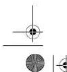

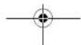
OBI_BUCH-2487-002.book Page 332 Wednesday, November 2, 2016 4:43 PM
332|Былгарскn
| Ви这样做ожимаф | ||||
| Каталовен Homep | 0 602 334 ... | |||
| ...501 | ...504 | ...507 | ...534 | |
| HommaHann no HanpekeHne | V 265 135 72 200 | |||
| Yectota | Hz 200 200 200 300 | |||
| HommaHah KONcymHpaHa MoUHocT | W 2500 2500 2500 3800 | |||
| HommaHah Na NpE3Ha MoUHocT | W 2200 2200 2200 3100 | |||
| HommaHae ToK | A 6 | . | 7 | 13,2 24,7 13,2 |
| Скорост на Вьтende на праzenхоД | min-1 | 6600 6600 6600 6600 | ||
| мас.Диамерп нашикразец ДSCK | mm 230 230 230 230 | |||
| Рezба на вала | M14 M14 M14 M14 | |||
| Мас сглесно EPTA-Procedure 01:2014 - 6e3 сномагателна рыковатka | kg7,87,87,87,8 | |||
| Клас на зашипа | + /T | + /T | + /T | + /T |
| Вidдацета | IP 20 | IP 20 | IP 20 | IP 20 |
Yka3aHHa 3a 3axpaHbHeTo
EnKtpnHCTpyMeHTe aactOT BHCOCOeCToTHa CHCTema n ce HyXdAe OTRTPa3aENIPOMeHHB TOK cYcTOTA bTnACHO dAnHATe H aTabekNTa.
3aJaCe ocHryr Taan HecTota, bEnkToponHcTpyMehTb TPhBbda bDe bKbUOHeK bK MeCToTeH npeOba3yBaten (BVKTe KbIOKaBaHe KbM HtOCHNuH KaTOK, cPraHnHa 336).
CtoHIOCTHTe Ha 3MbYBaHHa Wm Ca onpeDeneHH cbrNaCHO EN 60745-2-3.
HhfoMaH3a H3JIbYBaH wMn Bn6paHH
| 0.60230140. | 0.602301434 | 0.60230440. | 0.60230540. | |
| Равишиeto I Ha Ильчваима ум обикно- вениe | ||||
| Равишиeto Ha зуковою налгане | dB(A) | 72 | 82 | 79 |
| Мошост Ha зува | dB(A) | 83 | 93 | 90 |
| Ношpeденист K | dB | 3 | 3 | 3 |
| РавOTe creшуоагн'te: | ||||
| Пьіната стейност Ha Вибрацinteæ (be- Ктосяпа сума по trпite налравелени) in ношpeденист Ka оретени Stb- trал scho EN 60745-2-3. | ||||
| Шифobaning(rpy6ошнфobaning): | ||||
| a₁ | m/s² | - | 5,3 | 5 |
| K | m/s² | - | 2 | 2 |
| Полигане: | ||||
| a₁ | m/s² | 3 | 3 | - |
| K | m/s² | 1,5 | 1,5 | 1,5 |
| Шифobaning cшкypka: | ||||
| a₁ | m/s² | 3 | 3 | - |
| K | m/s² | 1,5 | 1,5 | 1,5 |
OBI_BUCH-2487-002.book Page 333 Wednesday, November 2, 2016 4:43 PM
Bmrapckn|333
| 0 602 306 434 | 0 602 324 40. | 0 602 324 44. | |
| 0 602 324 464 | |||
| 0 602 324 474 | |||
| 0 602 324 434 | |||
| Пьлесастийск на Вибраценте a1 (векторна… сума по Точу наразалени) и неор federеньост… К са ор federени наразно EN 60745-2-3. | |||
| Шимфobане (груюшимфobанe): | |||
| a1 | m/s2 | - | 6 |
| K | m/s2 | - | 2 |
| Полиганe: | |||
| a1 | m/s2 | < 2,5 | 4 |
| K | m/s2 | 1,5 | 1,5 |
| Шимфobане сшкука: | |||
| a1 | m/s2 | < 2,5 | 4 |
| K | m/s2 | 1,5 | 1,5 |
| 0 602 329 50. | 0 602 329 534 0 602 329 511 | 0 602 331 5.. | 0 602 332 5.. | |
| РавлиAMENTО A на заимьденийшу'm obinquно- вени e | ||||
| РавлиAMENTе на заимьдений - Моцност на заимьд Heopendeл end ST K | dB(A) 85 | 87 | 86 | 86 |
| dB(A) 96 | 98 | 97 | 97 | |
| dB 3 | 3 | 3 | 3 | |
| Равоч'te сшу'mozartnyштени! | ||||
| Пьеда-stюност на вибрач阴道е a, (Be'vekortnata cyma по лате наразалени): и неор dedенист К са on dedени: сыrtсан EN 60745-2-3. | ||||
| шу'mobache(rpy6шу'mobache): | ||||
| a₁ m/s² | 7 | 7 | 7 | 7 |
| K m/s² | 1,5 | 1,5 | 1,5 | 1,5 |
| Полигане: | ||||
| a₁ m/s² | - | - | - | - |
| K m/s² | - | - | - | - |
| шу'mobache сшу'mobache: | ||||
| a₁ m/s² | - | - | - | - |
| K m/s² | - | - | - | - |
| 0 602 334 50. | 0 602 334 534 | |
| РавлиAMENTО А НИЛБЕВАЙ SHM обикноево e | ||
| РавлиAMENTЕ на заимовOTе налгане | dB(A) | 86 |
| Мошист на зауka | dB(A) | 97 |
| НебореденnotК | dB | 3 |
| Равotierte сшутоагушитей! | ||
| Пьнота.stоимост на виславпite a.(векторна сума по trпITE h的答案н): m onореденnotСа с орeredenhi съласно EN 60745-2-3. | ||
| Шим波特е(rрубшим波特e): | ||
| a1m/s2K | 7 | 7 |
| 3 | 3 | |
| Почиралe: | ||
| a1m/s2K | - | - |
| - | - | |
| Шим波特е сшкура: | ||
| a1m/s2K | - | - |
| - | - |
Bosch Power Tools 1609 92A 36C (2.11.16)

OBI_BUCH-2487-002.book Page 335 Wednesday, November 2, 2016 4:43 PM
BbIapckn|335
Pepda3eH ekpaH (BHXTe phr.C)
OTHACCe 3a cneDHNTe moDenH:
-06023014. -060232440
-060230540.
-0602306434
Pnpa6oTaCrymHennoNoJoxEnHnCK17cAaKOBBnHa/DnCKOBATeHeNAeHTKaHnNpactHnHATnCK3aHHFOBaBe HnHaRn H3NON3BaIte npednaHnEepan9.
3axbahepe npdaaehn epaah 9 cbccnomaratenhata pkoxbatka 2.
MoTHPnAe Ha HnCTpyMeHTn 3a UHKnΦOBAHe O6uYkazHH
PepnHa npomHrte HactpOHN Ha eneKTPoHHCTpyMeHTa, Da 3ameHHe paboTHN HhCTpyMeHTn n Pnncoc6bneHn npEpaDn o octabTe npkebcaBe TaXPAHBHTo. T3n npedna3Ha MPRKa npedotpBaTBA HeBONHO BKNIOVAhe H eNEKTPoHHCTpyMeHTa.
Cb6pa3aBaire ce cdoynctHMITE pa3meHn ha pabotNHRE HNCTpyMeHH, dAmatebptb HA OTObopa Ip6ba da nacBa Ctbnanto Ha IeHTPOBAUHnFaHne. He KsnonBARE adan- TEPn HIN peDyHnpaun 3BHe.
-Почистете ваяз BCNCHKДдай,在КонTO ue MOnTHIPA-te.
CneMOnHTpaHetoHaabpa3HNHHaNCK,ppeHnDa BKNIOHTeENEKTOPHCTPMAHEn,ceBpeTe,FeDcKbTcE ToMOnTHPA npABHHo HMOKe Da Ce BpTrh CBO6HO. YpeTeCe,Ye abpa3HNHHaDckHeIOnHp aNopeNa3HHo KOKXHNHApYTH DetainnHa eNEKToHHCTPymHTe.
MOnTHpAneHaDnCK3aP83ane,ΦHNO HnH rpy6o ⅢNΦOBAHe(BKKTeΦHypD1-D2)
OTHACCe3aCNEDHHTeMOENH:
-060230440. -06023315..
-060232444..464. -06023325..
...474, 434 -06023345..
-06023295..
MoHTnpaHe
YBepTe C,ue BMOHTnPAH NODXNDH INPpeNa3EN KOxyx (BNKTeMoTHnPaHne HnpDna3HIne CbOpbKeHm", ctpnHa 334).
- Noctabete uehtpoBauu npnahe10Ha Bana 3.
OKOIO CTbIaIOTa 3a paobTHHnHHTcPmEHT Ha CEHTPOBaIu HA pHaNEU 10 e NOCTABEN PbCTET OHNKTcBEN MATEPHAN (O- npbCTeH).A NOPTbCTeHb TNNCBA Nn E NOpeH, npeH da non3BaTEpTOPAuuaIg HnAeH 10, rpa6Ba 3aDnKtien HoJa NoCTABITE HO B O-npCTeH.
-Поветаве ХенинабаразимьенИнсчурм龟11(Дикза разане,Фно Или рубошинфоба),кatoсвбраэbaTeпEOСКОТАHAВТБЕТА,HABA3A.
IocBaTe 3aTraata rKa12 Ha pe3bTaHa bana Taka, Ye KaHaN B cpeDAta Ha rKaTAt Da eobphar Harope.
- 3aTeHETe HgKaTc aDyIuKΦIOB KIOV 13, KATO cbuepeMeHHo CraeH eN KIOU 14 bJbPakte Bana 3, xaaeaHATa npdeBnEHIte 3a eJIa TcKOeCIN NOBpXHOCTn.
DemOHTHpahe
- 3adjpbktebaJ3aKc0eHHeNIOBbXHocnI craeyen Knju4 14
- PaabHnne TaaiKaTa 12 ot Bana c DpyuKIOTBNOH KIOH 13, Kato 3aDbPbKeata Bna C TaeeHHN KIOU 14, 3axBaHnat 3a. npdeBnDEHrte 3a eIeTc KOCEN NOBpHXOHT.
- Hapkaan34pnaaTe abpa3nBnHnD nCENTHPOBAaHnphianeoTbana.
EnektponHCTpymehn c 6ytoHa 3a 6nokpae Ha Bana 5
Othac ce 3a cneHnTe moen:
-060232440
-0602324434
-060232444
PnEeKTPoHHTcPmEHnC6yToHa3a6NkPaHeHaBa5 50tJAdA HeOBxOIMMOCCTaBbJaBb6bIe3aIbPkAnC taeueH KNOu PnMOHTpHaHe NaP6OTHe HcTcPmEHn3aWnHOboBaHe (BHXTe cHpyrE1-E2).
Htchkaitebytoha3a6boknphahe hana camaKorato Tbe bOKoi. BnpotneBeneCnya eEnekpOHNCTpyMeNTb TokeJa bJeNopeJen.
-Ппдг MOHTHpaHE Na paBtTHIN HcTpyMeHT HATCHeTe N3a4bKte 6byToHa 3a 6nOKHPaHE Ha Bana 5,3a 6nOKPapTe Bana 3.
MOHTPnAite XeNAHIN HNCTPYMENT 3a WnHPOBAHE (BHXKTE MOHTPnAte Ha NcK 3a PAnHe, FNO Hn Hpyo 6nHPOBAhe", cTpaHnA 335).
- Ottychete 6byToa3a 6boknpahe h Bana 5, 3a daocbo6-dine bana.
MoHTnpaHa rYmEn nOgNoKeHnck (BHXTeΦHypFA)
Othac ce 3a cneHnTe moen:
OBI_BUCH-2487-002.book Page 337 Wednesday, November 2, 2016 4:43 PM
Bmrapckn|337
- Hapka npopebepe dan npedna3nH npo0dnnK e cbp-3an npabvHIO.
B-Kaparate CESE-uenCnca 24 ha enekTPOHCTPymemTA B KONTAKTA Ha ChetotTHN pnoeobayATen.
CnTbOaMOKeTe Da BKNIOUHIE YCTOHTTHNpeo6paByBaten Km3XAPBaHbAuta MPeKa.
KaJa cBbPkeTe CpeTOnTHn pne06pa3yBaTeN KtM 3axPaHaBaUaTa MPeKs MaKeMe Ta npOteTe BpkoBODCTBOTo 3a EKCnpoAatau Ha CpeTOnTHn ppeo6baByatEn.
CneToba npoBepete noocata Ha Bbptene!
Поверка на посока на Вьртөн
IIOKcataHa bpuTeHe hBaNa TpRbGa daCbNada CIOKcataHa cTpeKnab pBpy ENeKPOTHCPTMeyra
Ako npn bpbohaanno BknloBahe (BnKte BknOuBaHne HkNIOBAHA nEeKTPoHNCTpyMeHTa, cTpaHua 337) BaIbCeBpTN B o6paTHa NocKa, Tp6Ba BcHaNrda NkNIOHTe EeKTPoHNCTpyMeHTa Ia ITOIeIITHe O3xaPbHaTa MPeka.
-Pa3BnHte OTOBBO BATA BHTNA 22 H OTOBIO N3BaTeDE BNOKKT4 21 O KopryNCA H CEE-uenCena 24.
- OcbO6ObE KNEIMHe HA KaJdBnH N HA HePnHn PNOBOD HNK O1 CbOETBHNEH N M OBTDN.
Cnep TOBA Bkapaiye KEmaHa HApHHN npoBODHnK L3 B OTbopaL1,aKnemataHa KaFABnnpoBODnK L1BtObopa L3.
3- AteHHeT MEANKHe BHTHOBe 23 bB B BNOXkata 21, 3a da 3AxAbaHE T PPOOBDHNiHTe.
Bkaapane BNOkKATA 26obpHIOB KOPNCA H CEE-ien cena 24 NTOHOZATHERHcE DAHTBNA 27
-HaKpaI npObepeTe DAnH npEaNa3HnT npObOdnK e CbP 3nH pApBnIO.
- OTHOBO BKHONETE eNEKTOPOHNCTPymHTA KSM 3XAPBA-taquata MPeka.
Pa6ota ceneKtponHcTpymEnTa
IyckaneBeknnoataa
HanseKHeHToN HeCTOTATA Ha H3TOUHHKa HA TOK Tp6B Da CbTBeTcTBaH Na DAHNHTe, H3NcHaHn HaTa5EknA-Ta Hae ENETPOHNCTPYMEnA.
PpOBepBaIe paOHTHe HnCTpyMeHTn, npEa dH 3N03N3BaTe. PaOToHH nHTCpTMeHT pRbDa a EMOTHPNAP 3EyKOpHO N da Ce BpTn, 63 Da oJOnpa HnKbDe. OcBaaIte Ro da CbPTn, npO6o6 HeHATOBapAaHe hAmAnko eHa MHyTa. He3NON3BaIe NOpeHn, 6BeuHN HnBHpauH paOHTn HnCTpyMeHTn. PpoeHn paOHTn HnCTpyMeHTn MoIa Da ce paApTuWt I da pNpHIT TeKxN TpaBM.
Nocabete Nyckobnpekbcay 1B no3nHn, H3knOeyo"KORA eNEKTPONHCTPYMENTb HE0aKaBOHOcnpap6ota,BbNPKHe y NcKOBnTpeKbCBAe Bno3nua.BKnOpEto. Taka npedToPbTaBare HeKoHTpOnnPAHO NOBTOPOB KNOJouBaHE n ENEKTPONHCTPYMNTea
PnDJIJa BKNIOHIE ENEKTPOHNCHPTyMEHTA OTHOBO, IpNOBepete NToOHKA HA TOK (BKNKTE, BKNIOVAIHe KbM HToOHIK HA ToK, cTspanHIA 336).
BnHAnrMbBOKbIouBaIte enekTPOHNCTPymeHTaKbMeCTOTTHNIIpeo6pa3yBaTeN,piDeA da BKNOHTEeCtOTTHNIIpeo6pa3yBaTeN KMc 3axpaaHBauata MpeXa.
3aJa nteHtE eTnepH, JbXTe eNekToPiOHCTpyMeHTA BkHOu- HcM GoKATO rO nONBate.
BkIIOUBAHe H N3KIOUBAHe Ha YecToTHnN Ppeo6pa3yBa-ten
PnJa Da BKNIOHTe ENEKTOPOHCTPymeta, Tp8BaDa BA BKNIOHTe UcctoTHN Pnp6pa3yabtn.
3aJeTMA pnoTeTe PbKOBoCTbTO 3aekcNoaTaIaH aTeOTTHnPeObpaBAYeRt.
BknoubaeHa nKnoubaeBa hneEketpOHHCTpymHTA cnpepaanenePbckBcaynIpbzraH(BHXteFHyprJa)Y
Othacce3aCneHnTeMoen:
-06023244.
-3a BKNOHVAHBe HJeEJKTPOHNCTPYMEnTa npeMeTeTe NcKOBINn PnKcBcAan Hnped.
-3aactonopnBaHa HnyckOBIN pIeKbCBa1 HAnCHete NyCKOBIN pIeKbCBa1 B npTeHNMy KpA,doKaTOycHTHe TpePauKaBAE.
- 3a HKnIOUBaHe Na eNeKpONHcTpyMeHTa OTnyCheetyCKOBria IpeKbCaBvA.1
PnnoTOHNOBHXIOJIeNcKpO npckbcaa1 nIpsboNEKO rHOHTAHCHETE HADOTy N CIEDTO BTO IORTHYCETE.
BknIOUaHne HnKIOuVAe Hna eNkTPOHNCTPymeta C npndaenpehneKbCBAH (BHXTe yHrpaJ2)
Othac ce 3a cneHHTe moDenH:
-06023014.. -06023295..
-060230440. -06023315..
-060230540. -06023325.
-0602306434 -06023345..
- 3a BknoBaHa nbe enKpnHcTpyMeHTA pneMeTeYn CCKOBIA NpOeCBAH HAnpehN cNeTO bAO npINTHcHeTc
-3a3actonopbaheHaHATCHATNpyCKOB NpeKcbay1
PnpeMeTeTne NcKOBnIpeKbCBAu 1 Oue Hanepe - 3a da HxKNOHTe ENekTPOHCTPymETA, OTyCHETe PNYCKOBIA INpeKbBAA1, pecn., ako e aactonopoe, ro hATNCHETe KATKPQBOEMHO N CIED TOBA OTYCHETe.
yka3aHHa pa6oTa
PepnHa npomEnHe HAcTPOKn Ha eneKTPoHnCTpyMA,da3aMeHrA PeBOHHn HcTPyMeHTN nPnCnOcoBneHHn Pnpn Da nOctabte npKcbaiTe 3aXpAHBeHo.Ta3n PpeJn3Ha MPKa PpeoTbPaTaBHeBONHtO BKNouBaHe HA eNkTPoHNCTpyMeTA.
BHNMAIATAE INP PONIPBAHNA KAHANIA BHOESCIN TCEH, BHKTEP AZDAENA, YKAKHAHNA 3A CTATWHA NKOKT'
AaTeaTbThe CeDpXnO nO nHaTa nO hCSeBHeToH cn Tero, noTactonopBaRe no NOxOxAuHn.
HpeptnoapaaeIteKpOHNCTpymEnaTO cTeEN, pNb KOrto bTpHTeHO My dCnPE.
CnEaHINHO HATOBAPBAHe HAn ENEKTPOHNCTPymEnHa ro ONaIaTe, KATO rO octABte Da paB0TH NArKIO MmHyTN HA npa3eH XoD.


MaKeHOnHcKn|341
KopHCTeTe H eneKTHPNHtAnapath, onpeMaTa,doaTOUHe 3a anaHTHe HTH. BO cTnAHOCT Co OBA yNATCTBO. nPHTo 3eMeTe H GoOBp aobTNHeYcNOBn HneJHOCTuTOpeBa da CEbPIH. KopHCTeBo H eneKTHPNHApanatHa 3a npyIpyrAOTpeBaOCBEN HabeDeHATA MOKe Da IIOBDE Jo ONACNH CYAIN.
CepBHC
PonpaKaHa HBaHnOT eNekPrHnAn apat CMee da 6He He3BpHeHa cmo od CTpaHa KBAHNKHyBaH 3tpyHnepcoHa cmo CoKOPHeBe Ha opHHaHnHpeEHN DenOBHa. cMo HaTo HauHH Ke 6HeTe ChpyHn BO Be3bEdnOCTa H aenekTPHnHnO n anapat.
Be36eHocHH HanomeHH 3a arOHH 6pycnHKN
OnuTHa 63e6DCHN HANOMEH 3a 6pycebe co 6pycha XAPHTa JnONPbAne
Baxn 3a cneHnte TnOBN:
- -060230540.
-0602306434
-060232440.
ObojeneKTPnHAn anapat ceynptpeyba KaKa anatka 3a6pcebe h anat 3a nonpahe. BHHMaBajte Ha cHTe 6b3edHcHn HAnomEHn, ynatCTBA, npkAaHn NodatoaH uTcTe Hn doBnHcBo nPnHnr HA ypeDt. Dokonky He BHHMaBate Ha cnedeHytneYnatBA, Moke da doJe do ENEKTPrHy dApO, noXapH/NNHe TseKnN NorpeDn.
Oboj eekpnwn anapat he norodhen 3a bpycebe, paobota co xuanny cheyn h cyebe co bpycnn noou. IOKoKny ro kopnCTHe eekpnHnOt anapat 3a HecooDBETHN HAMEHMOKE Da ce npdE3BkAAT ONACHOCT H NOBpei.
OnnH 6e36bnoCHn HAnOpMeHH 3a 6pycebe,paOteHe co KJHauHH YETKN CcyeBe co 6pyCN PIOOH
BaKm 3a CneHnTe TnIOBn:
-060230440.
-060232444,..464,..474,..434
-06023295
-06023315.
-06023325.
-06023345
Oboj eektpnH anapat ce npntpe6yba Kako anata Ka 3a BpCSeBc, HJHAna YteKa n BpCynHs 3a CceHe co BpCynnNooH. BHNMAJBAt HA CTe 6E6HeNOHN HANOMEH, yNATCTBa, pNkHa3n H NoTaOnu Hi TO CTn DObHne BO pnpnr HOpeDor. DOKONKy HE BHMNabe Ta cIeNHTE yNATCTBa, MoKe Jda NoJeDe o eektpnH ynap, NOKAPd HIN N TEEKN NOBEPDn.
OeKTHAnapHe norOed3a6pycebe co 6bpychaXapnHa nonnpabe. IOKONky ro KOPHCTte ENEKTHANatapana3HeCCOOBETHN HAMEHNMOKE da CEpeNDBHKaONACHOTN NOPBENJ.
Onth6e36dnochn Hanoemn 3a 6pycehe,6pycehe co 6pycha xaptnia,paboTebe co KxHauHH YETKN,nonpaBe n cepehe co 6pycnH nOoH Baxk 3a CHTNEOB
He KopHCTeTepnBopWToHe cneuJAnHO npedBdHEn Hnpenopaaund OpoN3BODHTENOT HaOBOjEneKTPhueh anapat. He Bn e3arapanHaapaBe36eDaHaYnropeBa, caMo 3apadn fakot DeKa npbopot Moke da ce npHbPCrHa BaINOT eKeKTPHeH anapat.
103B0BENHOT 6poj Ha BPTEXH Ha anatot wto ce BMETHyBA MOPA da 6hde HTO TONKY BCOK KAKO hAJBCOKHOT 6poj Ha BPTEXH HABeHn Ha eNEKTPNHHOT anapat. PInb6opot kJc beptn no6p3o od D03BOIHOHOT MOKe Da CE CKPHN DA JneTHe OD anapatot.
HAdBopeuHnOT nJametap Hde6eHHata HA anatot HTo Ce BMeTHBa Mopa Da oOroBaPaAT HaDMHe3NHTE BA BaHnOT eEnKTPyeh Anapat. IorpeuHo DMHe3NHOHpaTe anati 3a BMeTHyBaHe He MoKe BoBOHNO Da Ce 3auTtAT NIK KOHTpONHaPT.
ATHTTE 3A BMEHYBABe CO HABO JMOPA TOHO DA ODROBAPaT HA HABoJOT HA BPTeHOTAO 3a Bpycebe. Kaj ANATHE 3A BMEHYBaBe,TOC ME CMOPTA P cNOOMU NpHPa6Hnua,DJIAMETAPOT HA DYNKATA HAnATOT WTO CE BMETHyBMAPOdaOGRbApaHA DNJAMETAPOT HA NPHPcTAt HO pHbAHHNA. ANATITE 3A BMETHyBABe HE MOCKO TOHO DA cPNIPBcTAT HA ENEKTPNHHTO anapat, CE BPTAT HEPAMHomEO, BHbPpaAT MHOY jako HMOke daDobetdpoIyBcbe HA KOHPTONPA.
He KOPHTe OUITETEH ANATI 3a BMETHYBAbe.Ipead Cekoe KOpHCTBe, npOBepTe rAnATIE WTO CE BMETHyBaat KAKo HA Ip. dANH BpCHNTE NPOHN HMA CKNHAT DenOBn Hnpouen, DnHn Ha BpCHTne DnCKOBn HMa NyKTHAHNN, dANH CE nCTPOeHN HnH N3AbEHn, nDANH MOnaONaBaeHN HnK CPKEN HXnHa HxNHaHATA YETKa.DOKOKBYn BnADNE ENEKTPMHOT Anapar HnHAnATI TOE CBMETHyBA, npOBepete dAn eOuTTETH NnK npYOTpebE HeOTETEN anAT 3a BMETHyBahe. OTKAKo CTro npOBepHne H CTABHne AnATOT 3a BMETHyBahe, HnEMHOZONByte HA NnHtAa Da 6hDat BO SnMnHA HnHBTOA HnBKYehNHTan APAT H octabete ro anapatot DA BPTN EdNA HmHYta Ha hJbNCoc 6poj Ma BpTeKH. TObeKeTo OD, OUIETeHNTA aAtAH 3a BMETHyBahe Ke ce cKpWt BA TKOT HA OBOJ npobEH nepNO.
Hocete 3aunthn O npema.Bo 3aBCHOCOT yonTpebata,Hocete eueoNc3aunthTa 3aHnCTo, ouTHn H aunthTHO uOnHa. DOKONK E nTOptb6HO, Hocete MACKa 3a aunthTA o npab,3auTHTA 3a Cnyx,3auTHTHPAkAunu nn CneuJann PteChnHn WTO Ke B3auHTAT O qeuchuknHt NactAHNTn npb 6pybcbe Ha matepjanot. Tpeba da hn 3auTHnTte outhe od TyI'Te taeta noetaa HAOky, a ce hactahntn OD paoHHnata yonTpeBa HA ypeoT. Macktke 3na Tnp 1npab 3auTHn npn BnDnhyBaHeto MOpa Da ja fnnTPpaat npaba STno hactaHyBa npn YnOHTb6ta. DOKONK CY nIOKeHH Ha Iacia BpeBa NOIIO BpeMe, Moke da rO nrybIte cnyXOT.


OBI_BUCH-2487-002.book Page 343 Wednesday, November 2, 2016 4:43 PM
MaKeIOHcKN343
Cekoraa Koprctete Heoetetae 3te3Ha npn6Hmua co coDBBtHa roemHHa 0bnHK ha 6pyChnte nnoch. CoobEnHa Tnpn6Hma ja dprk 6pyChnta nnocha ta Ka hamaanyBa onaochta od kpuene Ha 6pyChata nnocha. Pnpa6Hmua 3a 6pyCHn nooh 3 aceoe ce paaNkybaat od npn6pHnue 3a dpyTne 6pyCNn nooh.
He KOpHCTe HcTPOeHN 6pyCN NIOu ON dIoreMn eEnKTPNHN anapatn. BpyCNTE IIOVNI 3a TOnEMn eENKTPNHN anATn HE CE npEINBNEHn 3a NOBcOK 6pOJ Ha BPTe3 aMaNTte eENKTPNHN anapatn M0Xe da ce cKpUar.
DyTH CnOJIaJIHbN 6e3eIHOCHN HANOMEH 3a CEHebe co 6pyCNHIOH
H36eHybaJte 6nokpahe Ha 6pychata nOva 3a ceebe Hnn nperoen pntnKoc. He 3eBpyBaJte npekymepno hao6kpeoBn. PneotobpaBysToHa 6pychTe IIOOH 3a ceoebe ja 3rOenemyBa HnHbata NCKOPHCETHOCT H KNOHOCT HA 3akocyBaHe HnH 6nokpahe H co TOA MOHOCTa 3a NOpateH yap Hn Kpuiebe Ha 6pychoTO Teno.
H3eRhybajrto noppaJeto npedn 3ad potnapkata 6pycha nnoa 3a ceehe. DOKONKY bpychata nnoa 3a cehehe BO JENOT UTO co opabotya j npinBnkyate noadaney o cebe. BO CNYAJ HA nobpaten yap. enekTPHHNHT anat co pOHTpKaTATA NNOA BMOKENJa ce OTPBN PIMKTHO HAC
Dokonkyce3aIaNb6pyChataNaOVA3aCeyHeHnBHe ja npeknHete pabotata,Knkyte roypenroMpKeTe moHPO,doKeNAooTae HdoJeBOcoTojoHa MnpyBaHe. He ce 6ohNyaje HNKoRa,6pyChata NIOA3a CeyHe WTO CE BPTn da ja BaDHTeOpe30,6dEJKMOke Da Hactane NoBPateh yapd.OTpkjte ja npKHHATA 3aIarabyBaBe npeMeTe rCOoDBHTHE MEPK.
He ro BknyuybaJte nobTOpHO eNekTnHNOt anapat,
Dodeka ce hao fo 8o denot wto ce o6bapObya.
OCTabepeB6ychata nnoa3a cyehebe da ro nocthrne
NONHOT BPTEKEN MOMHT, nped da npdoONKHTe CO
pe30r. Hnky, nnoHTaMoKeJaCe aIaanBn, da nnEria od
denot wto ce o6bapObya Wn Da npedn3BnKa nobPareh
ydp.
Notipre HnNooHnHnRoneMnte denOBn 3a
06paOToKa,3a da nHsEhetne HhNKoTd NO npatoe
ydpnpao3arnBnepHb6pyChNaNo7aCepehe.
ToneMNTe DenOBn ToC o6paOBOyBaat MoKe Da Ce
CBNAAT No CBOjATA TeknHa. DenOTu ce O6paOBOyBa
MOPaDa To nO pTe HaDBe CTpaHnO DnOHTA, KaKo BO
BnHnHa MeCToHa CHeHcE, Taka HnPAoBHNe.
Oco6eHb6nTe npTea3nHBn npDnabHckceHe BcKpHEnoNDpaJe, Kaco HnpMep, BO sND. BpyChata nOvau 3a ceepeJe Koja npceekna racobodnBn BOOpBDnueBKn, enEkpTnKn kabn nn Dpyn object MOKe da npedmika noPbateH nyapd
CneuJIHnB 6e6edHochn HANOMEH 3a 6pycehe co 6pycha XapTjHa
He KOpHCTepeNpIMMe3HOHPaHb6PcHn HCTOBH, TYK cIeTe Tn NODaTOUHTe Ha npOHsBOHTenOTa 10rEmNHATA h6PcHNT HCTB. BcPHCn HCTOBH, KO tCPWt HAD PBCHNTE DMCKBoM, MOKe Da npEh3BkAaT NOpeBn KaKO h NIOKnOPaBe, KINHeHe h BpcHnTE NIOCTOBH INIOBpATEH YdAP.
Cneunjannn 6e36ednochnn Hanoenm 3a tonnpahe
He Hn CnyuTajte naabate denobn H xay6bata 3a nonnpahe,oco6ebo Bprknta 3 npnrpcctyahe. Cmeette Hnnckpatete Hprknta 3 npnrpcctyahe.OnaBabenehtbe Bpkr 3a npnrpcctyahe konHtio ce bptat moTe da H pafat Baunite npcttn Hn da cearna bat Bo denot 3a 06pa0toK.
CneuJIannH 63e6dHocn HAnOpMeHHa 4a6oTebe co XKHMAHYETKH
BHMnabajte Ha Toa Daek N3a BpeMe HA Bo06HuaHaeta hyonpteBa HxuHAnHe YetKMOke Da ce H3ry6at denoBH OJ xHcata. He nI neopontobaybaJte XHnue Co BnOCK PHTNcOK Ha NobpUHHata. Denobite od XHcata MoKe daJIeTHa I da HABIE3AT HN3 neChata 06NeKa HnHN BO KOKATA.
Dokonky Kopchhte 3aunTHa xay6a, He dozBonybaJte Taa daojoBE KOKANTCO XxuHnHTe YETKHe BO ObIKNa HuaHjna HnN noHuei, aapadni npTnCOKOT n UeHTPHyflanHata cHa MoKe Da ro 3rOenemat CBOJot dJaMetap.
DOnONHTENH CNrpyHOCHN HANOMeHH

Hocete3aunTHnOuHa.
Kopcheteo coobetn ype 3a npe6apbyae,3a da r npohajte ckmhne tenektpnuu KaBn Hn Kocynpnae ce co nokanhto nepntpnjha 3a chabnybahe co ekeptnuha eheprjna. KOHTAKTO CO enektpnuHKn kAbn Moke Ja doBoJeNo JoXapn E neektpnuH ydpd. OotetyBaHBe Ha racBODOT moKeJa doBede Bo ECKnO3Ha. HbAerByBaTe BO BDOBODHH cCBN pndmBkyBa oUtctyBaIe Hn MOKe Da npednBHKa ekeptpuH ydpd.
De6nokpajre ro npKHNyBaovr 3a BknyBahe/ncKnyBaheBCTabeRo BO nO3nHja HcknyHeo,doKnKcy ce npKeHe HanoJyBaBeTo cctpyja,Ha np. no CHEMyBaBe cTpyJa HnN BnepeHe na CtpyHnOtn pnhKnkyoC Toa Ke cnpne He HEKOHTPOHPaHO pceTAPpaBE HyaepdTe.
He HONPAJTE 6PCHNTNE PNOH H 6PCHNTNE PNOH3a Ccehe dopeka He o naat. PNOHTHE 3a BPEME Ha pabotehtcSTAHyBaT MHOY KueKu
Pnpa6oata,dpxete ro eneKTPHNNOT anapat
pctc0 co DBeTne nnKn Hactane He BO chrypha
nonoxBa. Co eneKTPHNNOT anapat noCHrpyHo Ke
ynpaBvayabe ako ro dpxkHe co DBeTne nnKnH


OBI_BUCH-2487-002.book Page 344 Wednesday, November 2, 2016 4:43 PM
344MaKeHcKn
3auepcTe ro npaTeo oTo ce6pa6ryBa.10KoiKy ro 3auPcTHe co ypeJ3a3eTHyBaBe HIN MEHfEMe,TOAJI npaTeo To ce6pa6ryBa Ce pJxN OoupCTo OTKoiKy co BAata paka.
PnKnyte ro eneKTPHnHOT anapat h nponHcno 3a3emjeha cTpyhmapeka.PnKnyHnHauTaI npOdoNkHnT KaBem Mpa da HMaat pHyHKHOAHen 8aHTINTHPOBNDH.
Be36eHcHn HAnOMeHH 3a HAnOjYBaHeTo Co eHeprHa Jha BNCoKofopeKBeHTHN anATN
Be36eHnCHnHe npaOHTHe HANOMEHn 3a pnetbopaHOT hPpeKBEHNmuOPaTPO da ce noTHyBaAT! PoteTanNn opanouu 3oa Ke doBnEe Op npnoHBTeINOT hnpetbopaHTo HpeKBEHNu.
PtpBpOaTuHa pFKeBENH MOp Da ce 06e36edn co 3auHTHe npoCo dHpeHuaNnaCTpyJka Kora cakate da Ro KOPHNTBe OKOnKH, Kaede e Notp6Ha oc6eHa 3auTHa HnUaTa HcnpMep EnoKoDHa npa Pabota BO BnAkkn NPOctOpHNu Co MaTePiJan, Kaede To MoKe Da ce CooJa cnpBODoHnIpaNap, OTKKaXyBaHTo Ha 3auTHHOT npEe Co DnPeEHUNaHnCTpyJha IOBeJe Do ydAp, ONACCHOT oNIOKAP ININ CEPHO3HH NOBpEyBaHa.
3aHTTHHOTypeo co DnhepeepuJannha ctpya cme da 6bHe bprpaBaa 0Mpekata 3a HanojBaBe c ctpya camo od ctpana Ha ctpyu nepcohan. Camo taka moke da 6bHe zaraaparTnpaba 6bcnpekopKa fHyKnua
Hne3HHaHOHnFpeKBeHnHa na npeTbpaOHT ha FpeKBeHm Mopa na OOrBaP aT CO NOATouHTe Ha cneuHkAaHOna TnOka H bNcOKoFpeKBeTHnOT eNEKtpnuh anapat.
EeKtprHnHOT anapat Tpe6a da pa6oTH hcknyuBO coooaeTeH pnnkNOK.CEEpnnkYcOKOT mpa 6bnHe KOHCTpyhan aHomHHaHa CTpyja, koja uto n eotpe6ha 3a eektpmHHTOan apat (BHNJ.TexHHKIN noaTOU).
MOnthaKaTa HnPnKnyuKOT HnPKnKvYBaHTo HcAbSyBaHTo co eHeprJa Mopa Da K3BpWn Od CtpraHa HcTpyuHn PecOHaN KoJ e6oyuHa 3 NoCTanyBaBe Co CHCTEm HA BHCOKoΦpeKBHTHM anATH.
KopnCTe HcknyBOp opHmHaen Ka6en!PpeCekoe KopnCTeHb Hane ENeKTHPNHOT anapat npnoapeTe dnn eOHTeH yepoT, Ka6enN nPKnkyOKot. Ka6enr n PnKnkyOKOT He CMeT a Da Ce nonpabaat, tyKu Mopa a Da 3AmeHAT, 3aDa CE KsEBHAT OINACCHOT.
Onnc Ha npOn3BODOT MokHocTa

PnOHTAteRnCHTe HANOMEHN yNATCTBA 3a6b6ednoct.1peWKeH NACTAHN KAKO pesyntaH, od HnpEePKBByAbeNo 6b6bHcNOHt HAnOMEHN H NATCTBA MOKE da npedhBkAat eNeKTPueH yApd, noxak Hnnn TeKHN NOBepd.
Be monnme Oboperte ja npeknoneneta cTpaHHa co npHka3 ha eneKPTNHOI anapar, I npKeTe ja oTbPOHe aJdoEKA ro yntate ynATCTBTO aZyunptba.
YnOtpe6a co cooDbetHa HameHa
Baxn 3a cneHnte TINOBH:
-06023014.
-060230540.
-0602306434
-060232440.
-06023014.
-060230540.
-0602306434
-060232440.
EnekprnHnoI anapTe HameHer 3a 6pceHe 6b6pyChn XapTnHa no npurahe Me TaTINn Nnakpann Nnobpnnn 6e3 yonptoeBa H BA.
Baxn 3a cneHHTe TIOOBN:
-060230440
-060232444,...464,...474,...434
-06023295..
-06023315..
-06023325..
-060230440
-060232444,...464,...474,...434
-06023295.
-06023315..
-06023325..
EnktpnHOT anapate HameHET 3a ceebe,pybO bpcceHe nHTKaJIe Ha MetaIIH N KAMEH MaTePnJIaN 6e3 yOnIpO6a HA BOJa.
3a CneHcE Co KMOHnTH INBpyCn CpECTBa MopA da ce KOPNCH CnueHJIaAaHTWTH XaYb63 aa CneHcE.
PIN CIEUHbETo BO KAMEN NORPHKETe Ce 3a DOBOHNO BWMUKYBae HnPADbA.
Baxn 3a cHTTNOBN
CMeae da ce kOpDCTAT NcKnYHBO NcNpOaHHTe INoOobpeHRe 3aunTHn Xay6n HaterHyBaHKn HABrKn 3aObo jEontPrHne anapat.
Nmyctpaunjha KOMNOHEHTN
HymePpabaTo HcNkHTe co KMOHOHTe CcOdHecyBaHa npka30Ha eNekTPnHte anapatn Ha rpaHkata ctpaHna.
1 PpeKHyBa 3a BknyyBaIbe/HcknyyBaIbe
2DOnonHHTeNa DpuKa
3BpeHc03a6pyceHe
4PnHaBpeTeHTo
5 Konue 3a 6nokipabe Ha BpeTeHOTO
63aHTnHa xayba
7Ipa43aikcnpaheHa3aHTHtataxay6a
8KoIpaHn3aun
93aWHTA 3aDnAHKHe
10 PnKnyHa npnpa6Hnua co O npcten
11Ipoa3a6pycebe/ceuehe/ueiehe
12 Cte3Ha HABPTKa
13 KnycdoBa OTBOPn
14 BnyuKAcT Knyu Co WmpHnA 17 MM
15 T pkane3Ha HABPTKa
16БусEHHCT
17YmEHbpyceHdck
18 Mek dnck 3a nonipahse
19 XnHaHa YetKa
1 PpeKnHyBa 3a BknyBaIbe/NCKyyBaIbe
2DOnONHnTHeA DpuKa
3BpeHc03a6pyceHe
4PnHaBpeTeHTo
5 Konue 3a 6nokpuhae Ha BpeTeHTo
63aattnha xayba
7Ipa43aikcnpaheHa3aHTHtataxay6a
8KoIpaHn3aun
93aWHTA 3aDnAHKHe
11 Nnoa 3a 6pycehe/ceuehe/ueiehe
12 Cte3Ha HABPTKa
13 KnycdoBa OTBOPn
14 BnyuKAcT Knyu Co WmpHnA 17 MM
15 T pkane3Ha HABPTKa*
16 Bpycen nncr
17YmEHbpyceHdck
18 Mek dnck 3a nonipahse
19 XnHaHa YetKa
1609 92A 36G| (2.11.16) Bosch Power Tools


YnOtpe6a co cooDbetHa HameHa
Baxn 3a cneHHTe TNOBn:
EnekprnHnoI anapTe HameHer 3a 6pceHe 6b6pyChn XapTnHa no npurahe Me TaTINn Nnakpann NnobPnnn 6e3 yonptoeBa H BA.
Baxn 3a cneHHTe TIOOBN:
-06023345.
EnktpnHOT anapate HameHET 3a ceebe, rpybO bpcehe nHTKaBe Ha MetaHH N KAMEH MaTePnJaan 6e3 yNtpo6a HA BOJa.
3a Cneheco KMOHnTHIN BpyCncreDbTa MopA da ce KOPCNTH CnueJIaH YAaHTNIH XaYb63 aa Cnehe.
PnI cpeueHTo BO kAmEH NORpHXETe Ce 3a DOBOHNO BWMKyBbHe Na PBATa.
Baxn 3a cHTTNOBN
CMeae da ce kOpDCTAT NcKnYHBO NcNpOaHHTe INoOobpeHRe 3aunTHn Xay6n HaterHyBaHKn HABrKn 3aObo jEontPrHne anapat.
Nmyctpaunjha KOMNOHEHTN
OBI_BUCH-2487-002.book Page 347 Wednesday, November 2, 2016 4:43 PM
MaKeIOnHcKn|347
| Ви这样做�хштейнага aronna 6bychnka | ||||
| HommaHajna stryja | A | 5 | 10 | 18 |
| Бpoj ha npa3n ha bptexn | min1 | 8480 8480 8480 8480 | ||
| маск. disjametap ha 6bpycnhte почи | MM | 180 180 180 180 | ||
| HaboJ ha bprtehoto za bpycebe | M14 M14 M14 M14 | |||
| Текина соглесno EPTA-Procedure 01:2014 - co доронателна дршиka за рindушваье ha bivbaquinne | КR 7,17,17,17,1 | |||
| Клеса ha zaшпета | ± /I /I /I | |||
| Вид ha zaшпета | IP 20 | IP 20 | IP 20 | IP 20 |
Bucokopkebentha aorna6pycnka
| Бpoj на并向对接 | 0 602 332 ... | |||||
| ...501 | ...504 | ...507 | ...534 | ...511 | ||
| Hominen Hanoi | V | 265 | 135 | 72 | 200 | 72 |
| Ф�reichменя | Hz | 200 | 200 | 200 | 300 | 300 |
| Hominna Japana | W | 1950 | 1950 | 1950 | 2900 | 2900 |
| Hominna Japana Japana | W | 1500 | 1500 | 1500 | 2200 | 2200 |
| Hominna Stprya | A | 5 | 10 | 18 | 10 | 27 |
| Бpoj на пазни вргеля | min¹ | 6600 | 6600 | 6600 | 6600 | 6600 |
| Мас. дожаета на бруchnite пioч | MM | 230 | 230 | 230 | 230 | 230 |
| Hаов jo на ветенота за بрусяе | M14 | M14 | M14 | M14 | M14 | |
| Текиа сорлесно EPTA-Procedure 01:2014 - с准备工作драшика за рindушваende в�ы堕піе | КГ | 7,1 | 7,1 | 7,1 | 7,1 | 7,1 |
| Клеса на зашипă | + /1 | + /1 | + /1 | + /1 | + /1 | |
| Видназчпа | IP 20 | IP 20 | IP 20 | IP 20 | IP 20 | |
BcokofopekebeHTa aronha6pycnlka
| Бpoj на颇ten/артык | 0 602 334 ... ...501 ...504 ...507 ...534 |
| Hominahen hanoi | V 265 135 72 200 |
| Фразбениja | Hz 200 200 200 300 |
| Hominahina jaunha | W 2500 2500 2500 3800 |
| Hominahina hyaeseia jaunha | W 2200 2200 2200 3100 |
| Hominahinaстуяа | A 6,7 13,2 24,7 13,2 |
| Бpoj на пазни вретеки | min¹ 6600 6600 6600 6600 |
| макс. диметер на брусятце почи | MM 230 230 230 |
| Haboj на розенота збухсанe | M14 M14 M14 M14 |
| Текина сорлесно EPTA-Procedure 01:2014 - co polonitienna дошka за падушвае на виравлие | Кr 7,8,7,8,7,8 |
| Класа на зашита | © /I /I /I /I |
| Вид на зашита | IP 20 IP 20 IP 20 IP 20 |
Ynata 3a cha6dybahe co eheprnja
EneKPrnHrOpye e den od BnCOKoPkeBcHTEN CHCTEM M y nortpe6ha troPd3a Ctrpya co FpckBEnHa cdoBteHa h a ceuieauKuHouHata npohka.
3a da ce noctnthe oba a pfekBeHunja, mopa da c neobpaene eneKTPnuHHToD peO nTepoBapra Ha pfekBeHunja (BNDI PInpkiyukoh HanaoyuBaTeo co eheHriJa", cTpaHa 352).
Bosch Power Tools 1609 92A 36C (2.11.16)

OBI_BUCH-2487-002.book Page 348 Wednesday, November 2, 2016 4:43 PM
348|MaKeDoHcKn
BpeHocHTHe ha emncjHa ha6yUa opehen BO cornacnoCT co EN 60745-2-3.
HnΦopmaun3a6yaba/Bn6paun
| 0.60230140. | 0.602301434. | 0.60230440. | 0.60230540. | |
| Hinboto ha 38uk ha ypeodot, oueheto co A, | ||||
| TINHIO H3NECBya | ||||
| Hinbo Ha 38yueh npHIncok | dB(A) | 72 | 82 | 79 |
| Hinbo Ha 38yua jaHina | dB(A) | 83 | 93 | 90 |
| HecnHypnoct K | dB | 3 | 3 | 3 |
| Hocete zauHTa 3a clyXot! | ||||
| Bkynnite bpeiNoCTHa BnBpaunia | ||||
| (BeKTopcsk 36Op Ha TPrte HacOKI) | ||||
| HeCNrpynoct K pAdenH ce Bo cornaChoct | ||||
| co EN 60745 2-3. | ||||
| PobuHNCko 6pycebe (rpy6o | ||||
| 6pycebe): | ||||
| a1 | m/s2 | - | 5.3 | 5 |
| K | m/s2 | - | 2 | 2 |
| Ponipranbe: | ||||
| a1 | m/s2 | 3 | 3 | - |
| K | m/s2 | 1.5 | 1.5 | - |
| 6pycebe co 6pycen nHcT: | ||||
| a1 | m/s2 | 3 | 3 | - |
| K | m/s2 | 1.5 | 1.5 | - |
| 0 602 306 434 | 0 602 324 40. | 0 602 324 44. | |
| 0 602 324 464 | |||
| 0 602 324 474 | |||
| 0 602 324 434 | |||
| НиматICALS: | |||
| НиматICALS | dB(A) | 82 | 77 |
| НиматICALS | dB(A) | 93 | 88 |
| Héchéneyacht K | dB | 3 | 3 |
| Hocete zaußneta 3a clyxot! | |||
| БукшпITE BrepIJICHTN ha BvIbpaunu a, (BekTopcsk)3bOp Ha trpite HacOKN) HeCIMYPCHCTK JdaTeHn ce BOcorgnachocT co EN 60745-2-3. | |||
| Повшнско 6顺序e (rpy6bpycebe): | |||
| a1 | m/s2 | - | - |
| K | m/s2 | - | - |
| Полигалы: | |||
| a1 | m/s2 | < 2,5 | 4 |
| K | m/s2 | 1,5 | 1,5 |
| Буссени co 6顺序ипст: | |||
| a1 | m/s2 | < 2,5 | 4 |
| K | m/s2 | 1,5 | 1,5 |
| 0 602 329 50. | 0 602 329 534 0 602 329 511 | 0 602 331 5.. | 0 602 332 5.. | |
| Hiberto Ha 38yK ha ypedot, oceheno co A, TININIHO KIeHcyBa | ||||
| Hibro Ha 38yuH npHTincoK | dB(A) | 85 | 87 | 86 |
| Hibro Ha 38yuHa jaYnHa | dB(A) | 96 | 98 | 97 |
| HeckryphocT K | dB | 3 | 3 | 3 |
| Hocere zaHTHna 3a clyxot! | ||||
1609 92A 36G| (2.11.16) Bosch Power Tools


OBI_BUCH-2487-002.book Page 351 Wednesday, November 2, 2016 4:43 PM
MaKeIOnHcKn|351
MoTHnpajteHnIIOuHTe3a6pycebe,ceeuheHNN 电ctbe(BNDCNKND1-D2)
Baxn 3a cneHNTe TnNOB:
-060230440. -06023315..
-060232444,..464,-06023325.
474.434 06023345..
-06023295..
KopncTebe
- YBepertce,IekaeMOHTnp xayba(BuDnMoHTnpaHeHa3awTNTHTEypeDn", ctrpa 350).
- NocstabeTJeJa pnnknynHaTa npra6hNiua 10 Ha bpeTeHOTo 3a 6PcSeHe 3.
Bo npHKnyuHATA nppab6HHa 10 0kony ueTppanHOT BHeue cIabeHn nactiueHdE (OnpCTe).DOKONKy HeoCTHa O npCTeHOT Hn eOtTeH, MOpA Jda ce ZamEni PpeJ da ce MOHTHpa npHKnyuHATA nppabHHa 10.
- CtaBeteTo nocayybaHOT anat 3a6pycBe 11 (nnoya 3a 6pyceHe, ceeHe mN uCteHe) Ha BPetehoro 3a 6pyceHe 3.
- Czabaeta ja 3a3e3Hata HABPTKa 12 taKa HA HABoJoT Ha HABpTkata, To 3peDnHa, da6HHa 3aTe3HaTt HABPtKa nokKaYbHarope.
-3aupadepete ja aatae3hara Habptka co knuyot co daa OTbOpH 13,doeka co Bnhyuksact Knu 14 jeKphtke IOBpuHINaHa Ka NnuYt HApBTeHOTa 6pCyebe 3.
OCTpaHbBaBe
- IqKTe ro Ie pOCTo spEroHOTo 3a6pCHe3c0 BHNUYKACTOHN KNYa HOBNJHHATAH KNYHOT14.
OdpTeJa 3ateHata HABTka 12 Co KnyoT co DaB TObOPn 13 od BPteHToTO 3a 6pyCHe,doIeKa CO BNYuKACTHO Kny 14 Ke dpKHe NaOBpuHHata Ha KnyoT. - 黎聶嶽詞 號nncsodobatenno anatot3a bcycehe KaKo n pnpkNHyata npipA6hOnD 0BpeHOTo 3a Bcycehe.
EnektpnHn anapath co konue 3a fHKpHaBe Ha BpeHTo5
Baxn 3a cneHnTe TnOBn:
-060232440
-0602324434
-060232444.
Kaj enektpninn anaparin co konque 3a fkncknapba he bBpehto5 otnara dpkeheto co bnlykact kny npm Mohtakaa h naatot a3bpcyene (Bnbl cnncn E-12)
KoNcTeO 3a 6nokHpae HbpeTeHOTo AKTHBpajre To cmoDOKONkypeTeHOTo 3a 6pycebe eBOCtOJbHa MnpyBaHe. Nnaky eNeKTPnHnO T anapat Moke da ce OHTEN.
- PpEynopTe6a npHTnCHeTe Ha konHTo 3a PhHKcPaIbe Ha BPteHToTe 5,3a De ce KHCpaBPteHTo 3a bpCeHe 3 nDpKeTo r konHTo pNTHnCHto.
-MontnTpaJre no nocakyaBaanot alat 3a bpycehe (BINH MOnThpajre nnIpnOte 3a 6pyceHe, ceeHe Hnn YCHTeHe', strapa 351).
- OtnyTote ro KonHrto 3a fHKCpHaBa HApTeHOTo 5,3a da ce AHTBpa MExAHMOTa fHKCpHaBe Ha BpTeHOTo 3aOpycHe.
MoTHnpaHBe Ha rYmEHnOt nck 3a 6pycebe
(BHnCnNkaF)
Baxn 3a cneHnTe TnOBn:
-06023014. -060232440
-060230540.
H00601806434
KopncTeHe
- Ybepete ce, deka ce MOHTHPANH 3aHTNHTA 3a paue H IOIOHOHNHTA HAPa (Bnu, MoHTPbAbe Ha 3auHTNHte ypeD, cTpa 350).
- NocstabeTJeIgMeHOTnIKNc3aBpCSeHe17NaBPteHToHO 3aBpCSeHe3.
CTABTEFOHNCTOT3a6pycbe616HAYMENHOHTDNNCK3a 6pycbe6。
CtabeteokpyrnataHaBpTKa15HaHabojorHaBpeTeHOTo.
-3aupapefete ja OKpytnata Hapktca KO knytco JOBA TOBpO 13, NOkeCA BO NUYIKACT KNY 14 Ke JpnKe Ha NOBpHnHATA HO KNYOT HA BpTeHOTo 03 6bpycehe 3
BHIMABAJTe,OKpyrTaNaHabPka15da6nEneNoCHO 3aipapheHa HcNtAkhHHTaHa YmEHNOJDCK3a 6pycceBa,3a He npveepn p6pcyeBnHCTOT3a6p 4a6nBe3aTeHAT.
OcTpaHyBaBe
DekreTe ro UcPtoB ePeToHOTa 3o BcPeeBte 3 co BnUHbNACHT KOH YA NOpBnHIIHNA HcKTOY
Odpptete ja 3a3eHata HABPTKA 15 co KnyoT CO DBA OTBOPN 13 od BPTEHOTO 3a 6pceHb,doKeka CO BNIyIuKACTHO KUY 14 Ke pKHe Ha NIOBpuHHATA HA KNYoT.
- NopbteTcEto TnHOT3 aBcyCbeH rYmEHOTN DCK 3a bCyBeOd ABpTeHOTo 3a BCyCbe.
MOnTHpaHBe Ha MeK dNc 3a nonpaHBe (BnH cNkA G)
Baxn 3a cneHnTe TINOBN:
-06023014. -060232440
-060230540.
-0602306434
KopncTeHe
BHHMABAJe Ha Toa, HABOJOT HA MEKOT JNCH 3A nonnphe To4No Da oJIOBapHa HABoJOT Ha BpeTeHOr 3a 6pCyHe (M14).
- Ybepete ce, deka ce MOHTHPAHN 3aJIITHATA 3a paue HdoJHOHNHTApaPA (Bnu, MoHTPabe ha 3auITHNTteyepe, cTpaHA 350).
3abpybaje ro MEKHOJ DNCK 3a noNHPaBte 18 Ha BPENHOTAO bkycebe 3, cdoNEKA UpCto He HaneHe h aOBPnHnHa HkyoHT oBPeHTo 3a 6pycebe,doEKA CO BNYuKACTOH Kny 14 pOKeTe HACPOTH NOBPinHAta HA knyoT HpeHTo 3a 6pycebe 3.


352 | MaKeHOncKn
OcTpaHyaBaHe
3aBpybajre foKCHPAHnOT MEK DnCK 3a NoHNpaBe 18 CO BNYUKNACT Knyu HA NOBUPHHATA HA BpTeHOTo 3a 6bpcebe,doNdeKa co BNYUkactnO Knyu 14 Ke dpKHTe Hacnpotn NOBpuHHata Ha KnyoT HA BpTeHOTo 3a 6bpcebe 3.
MOHTnpaBe Ha XnHauHH YeTKn (BnH CnHa H)
Baxn 3a cneHnTe TnNOBn:
-060230440. -06023315..
-060232444,...464. -06023325..
474.434 -06023345
-06023295..
KopncTeHe
BHHIMABAJte na ToHa, HAOJOt HA konHAnHne TeyKToNoHa daOrobapara ha HAOJOt ha BpTeHOnoTa 6yBeCne M(14).
- Ysepepe ce,Neka ce MOHTIPaHa 3aaTITATA a3 paue H onDonHnHTeHata papa (BmD. MoHTIPAHe Ha 3aHTIHTHTE yepdi, cTpaH350).
3AbyrByaJre ja nocayBaHATA KmHa YehTe 19 (NoHccte nn HIOccte YtKa) Ha BpEtoHO 3a BpCyebe 3, cdoKeA bcpTo He HanHe HA NOpBpuHATA KaNyOHTa BpTeHOTo 3a BpCyebe,doKeA CO BInyUkactnoT KnY4 1dPkeTe HacipOnn NobpHnata HA KnyOHTa BpTeHOTo 3a BpCyebe.
OctpaHyBaHe
3aBpybajre ja qmKcnpaHata KnHa HcTka 19 co BnUyNkact Knyu Ha NOBpUHATA HA BPETHO T 3a 6pcyeHe,doEka Co BnUyKAcTHot Knyu 14 Ke DpXHTe Hacipnoi NobpUHATA Ha KnyOT Ha BPETHO 3a 6pcyeHe 3.
BwmykyaBaHe Ha npaB/ctpyroTHH
PpabaOJ MATEpHJaNHTe KAKo HAp. CnoEsb BoJa, HEKOn BnOBn DpBO, MINEPAHm METAn EaBHe WITETHa NO 3ApBaJTe, ODonPiapHeTo HIN BMOYBAHbTo HA TAKBaTATA npBaMoTe Da PnpDnBkA aneprcknpeakun HnHn 3AbOyBaBaH a DNHNHTe NATMuta HA KOPCHHKOTn HnHnata BO OKONHHATA.
OpOepeHNeYcTHeKHNpABKaHnAp. npBnOdabHn 6bKaBaJat KaKo KaHeporeHn,OCObEO KOnkNcBE 0cKOMbHaHJaC oDonOHNAtHeHHcYcntAhn (XpOMaT, cpeCTTA3a3aHTNa HApB0). MATEpIbnante IIO codPax a3e6t MoKe Da bHnat ObpaBtyBaHm caMo O ctpHaHa CTpyHn Hnla
-3a0a,doKoIKy eB03MOxHO,KOPHTeTe COOJBeTeH BmkyBa4 3npa3BaMATEPHJANOT WTO CE6bpa078ya.
- NpRnKxTeCe3aDobpaIpoBtepeHOCTHaPabOHToMeTc.
Ce npenopaBvBaHoene HcnaMa 34 aauTnA pnn BnuHbuaBaHTo eO knaca ha fnntep P2.
BHHMaajate Hna BauKnKeIro pnnHn H na Bauiata 3emJa a3a MatepHjnT oJ ro obpObaryTae.
N3e6Hybajte co6paHc npab Ha pa6oHTO MECTO. PpaTa hco MoKe da ce daanaii.
PpHKnyoK Ha HanojyBaHeTo co eHeprna
3a ynotpe6ha eneektpnHnre anapatni notpe6b Hne npetbopau Ha pfekeBENHN, KO npno3beByta troFaHa stpyja co pfekeBENHa cooDBeTHa Ha cIeunHkAumOnaT aNoHka.
IPTeBPOAHH A ppeKBENH HMA BO PAJIHNH NFOEMHH CO pAJNHNH PpeKBENH, CekyJAPn HAIONH HOMIHAN JauHH. IsbOPOT HA pIeBPOAHTA H ppeKBENH 3aBmCH ON eNEKTHWHTE anapath KOH WTO tpeBa da c npHKNYAT. NpaJatre coet Oa BAAHOT dNCTPHBYET 3a Bosch npn IsbOPOT HA IpteBPOAH A ppeKBENH.
EEnKriPhyHnO tI apar ITO doBmBate co cneuJaihen Kaben oJ eTepHn MeTp n6e pnnnyoek.3aJa ce npTuTH Bo yOnTeP6ba, cneuJaiHnOt Kaben mOpA da ce 0be6edn co Teybopononee CEE-npKnuyok (KeHeTmRkDaKHaHO6oJa zEeHa).
OcBeHToa, eEnKTPNHTAnapat MoKeJa 6nHe onpeMeHco
KoMeepJaiHn3aHTNIH NpEKNHByAa 3aMOTOPa
3aHTNHa oJe pONTPOBAPBaYBa. JeTOTe 3aNoDECbAe Ha
OBOJ 3aHTIeH NpEKNHByAa 3aMOTOP MpaJa ja NOkPbHa
HomHNHATA cTpyJa hEneKTPNHTHOAPanat (BNi
"TexHHKnNNDatoQn"). 3aHTNIHNT NpEKNHBya 3aMOTOP
MpaJa peATnPa 3aNOMAny od EDAckCyHa.
3a Toa NoOHYBAJTE FM 6besedHOCHHTE HANOMEHn H ynatCTBOTo 3a MoHTAa BO nATCTBOTo 3a paBoTa Ha 3aHTMHnTO pKneHHyBa 3a MOTOP!
MoTHKpaHe Ha CEE-npHKnyOc (BnH cnnK1-12)
Onabaete H, Taabe TaebpTK 22 Hnabnehe T o doaKOT KO a PNOHUYK O1 20 k KJHHUETo HA CEE PNOHUYKOT 204
HcEeTe Ro nAactnHOTo CEue 25 cooBETHO Ha
JiJamatapot HA cneuJaanHOT Ka6en HA eKENTPMHOT
anapat HBMHTe RO CEE-KyKmUToHa To pNkynKOT
npkcy cunjAnHOT Ka6en.
CnpOBeTeI HcHnPte KHN H3K KaBcNcKa yBoDnHa 20.
OnababeHTNCHETHPNTMAN3ABTOK2B0BOJDAOTOKOTa 1PKNKNYQK1N BKNYUcTEFHN METAHNOTnpCTeH3kaPeHATAKUaL1B KOHTAKTHN0T
Meta/HHOT pCtE h3 cHATA XHIIa L2 BO KONTAKTHN0T OTBpL2,
MetenHNOT npCTEN 3a upHATA XmuLA L3 BO KONTACTHHOT OTBOP L3
KAKU M EITHJOT NIOCTEH HA 3EJEHO-KONTA TAA KUJA BO 3AANTHTHOT KOHTAKET HBOTD
NIOBTOPHO 3AETHEHETIHTYHTIPNTME MAH3ABPTK 23 BO DODOTOK3a npKryoK 21,3a da nФKcnpate YETHDNTE KHN
- Itoa a3aterhe J a Kaenckata ybaOHa 20 OKony
QIeHnOT Kaenco CO oBnora HA Kaenot, TAKA WTO Hema da
HMA a3aterHYBaHe HA metaHInTe PpCTEH.
- NIOBTOPO BMETHETe ro daDatoKOT 3a npHnYyOOK 21 Bo KyKHTeTe H CEE-pnKnyOoKOT 24 H NOBTOPO 3aTERTHe Tn DBe TaBPTNK 22.
- Ha Kpa jnpoBepeteJa npabunHnataykuHa ha SAHTIWTHOTCPOBNOHN
CTABETEROCEE-PPHKNYQKOT24HNEENTPHINHTANAPAT BO PKNHYHNOKHEKTOH NA pNETBOPAHOI HOPEBENHIM


OBI_BUCH-2487-002.book Page 353 Wednesday, November 2, 2016 4:43 PM

MaKeIOHcKN353
Cera moxero dao npknnyntpeptbapoyt ha pkekbennna Hanaiojybaheco ehepna.
Kako ja to npnkiynte npetbapoyat Ha pfpekbeHnHa h annojbyaheo eieepnja, noenneHte Bo yanrctboto 3a pabota Ha npetbapoyat Ha pfpekbeHn.
Ha kpaip npoBepete ro npabeuot ha BpTehe!
PpOepyBaBe Ha npabeoH aBpeHe
PnabeoT HA BpTeHe HA BpTeHTo 3a 6pyceHe Mpa da COOBeIECBYbO c03HaKATA 3a C1peIKA Ha cIHKA tHa enEeTKPHINOT anapat.
AkoBpTeHOTa3bpyceHe npn pIb0To IyUtaBe BO ymptpeBaCe bPtn BO norpeHEn nPaBue, [Bn] BknyuBaHe/HckNyUbaHe Ha enEKeTPhNHOt anapar", cIpaHa 353),MOPa BeHua Da To HckNyUte Hne EKeTPhNHOt anapar Ha To HckNyUte O HanojyaBcTo co eHeprJa.
Oho OaabeTn ABTe 3abTKn 22, n NobToHo HneTe ro doatokot 33 npKnyok 21 od Kyknteto H CEE-pnKnyok 204
- Onababere IN MTENHHTA NPCTEHN O KaΦeHATA HJXUO DAHNHINTO KOHATKH TOBPD.
- Ptoa CTABETe Io METAHNHT pIcTeH HA UPHATA XHJU L3 BO KOHTAKTHHOT OTBOP L1 H METAHNHT npCTeH Ha KaFeHATA XHJU L1 BO KOHTAKTHHOT OTBOP L3.
- NobtropHO 3aJHETe HnMANTe 3ABPTK2 3GdoTAPOK3a 3PnPKUYQK1 3aJaHnDMKNPATE XINJNTe
IIOBTOPO BMETHTE ro doatokot 3a npnHnyoK 21 BO kyuHtTo H CAEE- npnHnyoKOT 24 H noBTOPO 3aTeHETe nDiTe a3BPTN 22.
Ha KaJa npoBepete Ja npaBnHnHata dyKnHJi ha Ha ZaHTHnHTN cIpoBNOHN.
- PnKHyuey eTo eNekTPrHcHOT anapat noBTOPOHa hanoJyBaHe co eHeprija.
Ynortpe6a
CtBaIbe Bo ynotpe6a
HANOHO pKBeAeHunjata HA HsBOpOT hCTpyJa mopa Ja oTROBaapaa Ha noTaOnHTe Co cneHcHkauHOnata nnOkaHa NEEKTPNHnOT anapat.
Ppeynotpe6ata npoBepete rnaatnte 3a 6pycehe. AnatoT3 a6pycehe Mopa da 6neMoHTnpaH 6ecnPekpno H da MoKe cno6Dn da ce BPTH. HanpaTe np06a od HajMaNky dEn mHaNYta 1, 6e3 da ro KOpKhtte anapatot Ha Matepnlan. He KopcHete OuTEtEH, HETPKAE3HN HAn atn 3a 6pycebe wTO B6PpaaT. OUTeHene tAanl 3a 6pycebe moKe da nyKHAT da npednabkkaat nobpeju.
Noctabete ro npeknhyaot 3a BknyyBaBe/ncknyBaBe 1 Bo no3uJa ha NcknyeHO,ora enekTPhHOT anapat HeoeyKaHo ja aHa npa pabotata, hako npekHybAOT 3a BknyyBaBe/ncknyBaBe 8 Bo no3uJa ha BknyuHo. Co Toa Ke CnpeneHe HEOKTOponPiHpeCTAptnpaHe Ha ypeDt. PpOepete Ro HanojBaHaeto Co eheprJa (BnD,IIpKnNyKo HA HanojBaHaTo Co eheprJa", cTpaHa 352), nped NoTropHo Da Ro BknyHrEeKTPnHHT anapat.
Cekorai npB0 nobp3e fo enektpnHHOT anapat co nptbopay hФeKBeHNu, nped da ro pHKNHyUe nptbopayh foΦpeKBENH u CTpyJHa mPexka.
3a da ce 3aaTeHn eepjwa, BknyyBaJte ro enekpnHHOT anat cmoDOKONky To KOPACTNE.
Bknyybae/ncknyybaeHa npetbopaOT Ha pkeBENHH
HajnpB0 mopa da ro kAnbnapre npetbopaoht Ha dpkeBnHn, pnd a MoKeTe da ro BknyuTe eNeKtpnHnO anapat.
3a Oba cnedeTe ro ynataCTB0To 3a pa6Ota Hn pnetBopauOT Ha PΦeKEBHUN.
BknyybaBe/HcknyBaBe Ha eneKtpnHOT anapat co Chryphocen npeKmHyBaH Na 3raBe (Bnu cnHa J1)
Baxn 3a cneHnTe TnOBn:
-06023244.
3-6 Bkynyyaba haenektprnHKnHAp anapn, nprrchteRo npkeknhyaaba 3A kynyyhae/bcknnybya 1 Hanaiped.
-3aФнкрпаьeHa npeKHyBaHOT3a BkNvyBaHc/HckNvyBaHbE 1 npnncheTe ro npeKHyBaHOT3a BkNvyBaHc/HckNvyBaHbe 1 Hahnped HADNYdoDEKaHeCEBKNON.
3 AnKnyBaHBe HA ENeKTHPNHO anapat OTyWTeT ro
npKnyBaHOT 3a BKNyBaHBe/HcNkyBaHBe 1.
Pn HKnCpHn pKnyBHyAa 3a
BKNyBaHBe/HcNkyBaHBe 1 KpAIO KpIHHCHe HHa3aI
HnADOn nNoTa OTyWHTeT ro.
BknyybaBe/ncknyBaBe Ha eneKtpnHOT anapat co chrypnoec npeknhybau (BmKn cnnka J2)
Baxn 3a cneHHTe TNOBn:
-06023014. -06023295..
-060230440. -06023315..
-060230540. -06023325..
-0602306434 -06023345..
-3a ctababe Bo ynortpe6a HA eneKtpnHHTo anapat pntncHETe to npkeHHBAHO3a BKNyHbAe/HcNkNHyBaHe 1 npDxKeTo npnTHca
3a3aunpcbyBaBe Ha pinnCHATOH npeKHHbA 3a BknuyyBaBe/HcknuyyBaBe 1 Tpyhere ro npkeHHbAOT3a HcNnuyyBaBe/BknuyyBaBe 1 Nohapie.
nepa ro hcknyche enektpnuHHOT anapat,ocnobodete ro npKNYBAHTa BKNYyBaBe/HCKNYBaBe 1 oH. dokonykToe bOknpah, kpato npHmCTHe ro npKNYBAHTa BKNYyBaBe/HCKNYBaBe 1 n noTa ocnoBodete ro.
Cobetn npna6oTebeTo
PpeKHeTe ro hanojBaBeTo co eHepRJa, npE da NoHHeTe rro noDcEByate yepDo, da MeHyBate DnEOB on OPemATA mOnDOKONJyDNOPE BpMe He CTe RO KOpCTeNe EneKTPHHOT Anapat. OBHe MepKn 3a npEpyPeBaBe To cPieyBaAT HeBHmATEHINOT Clapt Ha eneKTPHHOT Anapat.
BHMMABAJTE HnpoCENBE BO HOCEKHTE SMIOBHNaHemEn 3a SttHaKa
Bosch Power Tools 1609 92A 36C (2.11.16)


OBI_BUCH-2487-002.book Page 356 Wednesday, November 2, 2016 4:43 PM
356 | Srpski
Ne promenjeni utikaci odgovarajuce uticnice smanjuju rizik elektricng udara.
Izbegavajekontakt telom sa uzemlienim povrsinama kao cevi, grejanja, sporet i rashladni ormani. Postoji poveci raniz od elektricnog udara ak je Vase telo uzemjeno.
Drzite aparat Sto dalje od kišë ili vlaçge. Prodor vode u elektrikni alat povcavir zirak od elektrokog udara.
Ne nosite elektricni alat za kabl, nevesajte gali ne izvlacite gai uzticne. Drzte kabl dalje odvrile, ulja, ostrih ivica ili delova aparata koji se pokrecu. Ostecen ili uvmutl kablov povceavaju rizik elektricnog udara.
Ako sa elektricim alatom radite u prirodi, upotreblavaje samo produkte kablovke koji su pogodni za spolju upotrebu. Upotreba produktog kabla uzemljenog za spolju upotrebu smanjije rizik od elektricnog udara.
Ako rad elektricnog alata ne moze da se izbegne u viaznoj okolini, koristite prekida strujne zašite pri kvaru. Upotreba prekida strujne zašite pri kvaru smanjuje rizik od elektricnog udara.
Sigurnost osoblja
Budite pažljivi, pazite na to, sta radite i idite razumno na posao sa Vasim elektricni imatom. Ne koristite elektricii alat akto ste umorni ili pod uticajem droge, alkohola illekova. Momenat nepažnje kod upotrebe elektricnog alata moze voditi ozbiljinm povredama.
Nosite licu zastitnu opremu i uvek zastitne naocare. Nosenje licne zastitne opreme, kao maske za prasinu, sigurnosce pieme koje ne kiizu, zastitni slem ili zastitu za sluh, zaivo od vrste i upotrebe elektricnog alata, smanjjuu rizik od povreda.
Izbegavaje nenamerno pustanje ud. Uverite se da je elektrici ni at alkijcuen, pre nego sto ga prikrjcuite na struji /ili na akumulator, uzmete ga ili nosite. Ako prilikom nosenia elektrciagalata drizte prst na prekida'u ili aparukluken prikrjcujete na struji, moze ovo voditi nesrecama.
Uklonite alate za podesavanje ili kluceve za zavrtnje, pre nego Sto ukljcitte elektricni alat. Neki alat ili kluc koji se nalazi ut rotirajuces delu aparata, moze voditi nesreca.
Izbegavaje tonenormaln dranje tela. Pobrinite se uvek da stabilno stojite i odrzavajte u svako doba ravnotezu. Na taj naclin mozte bolje kontrolisati elektrici ni alu neocekivanim situacijama.
Nosite pogodnu odecu. Ne nosite siroku odecu ili nakit. Dr'ite kosu, odecu Irukavice dalje od pokretnil delova. Opusteno odelo, dugu kosu ili nakit mogu zahvatiti rotirajuci delovi.
Ako mogu da se montiraju ureddjia za usisavanje i skupljane jraceine, uverite de la si prikrljuceni i upotrebljeni kako treba. Upotreba usisavanja jraceine,. moze smanjiti opasnosti od pryase.
Brižljiva upotreba i ophodjenje sa elektrčnim alatima
Preopterejute aparat. Upotreblavajte za Vasposao elektrici alat odredjen za to. Sa odgovarujcimelektrinim alatom radite bolje i sigurnije u navedenompodruciu rada.
Ne koristite nikakav elektricni alat ciji je prekidaču kvaru. Elektricni alati koji se me zevice uklujciti ili iskulcit, je opasan i mora se popravitvi.
Izvucite utikac iz uticnicne i/ili uklonite akumulator pre nego sto preduzmete podesavanja na aparut, promenu delova pribora iii ostivae aparat. Ova mera opreza sprecka vnenameran start elektricnog alata.
Cuvajte nekoriscene elektricne alate izvan dometa dece. Ne dozolvajate koriscene aparata osobama koje ne poznaju aparat ili niscu profitcale ova upputstva. Elektrici ni alati su opasini, kada ih koriste neisknusne osobe.
Odrzavajte brizljivo elektrici nal. Kontrolsife da li pokretni delovi aparata bespekno fungcioni su i ne,lepe",da li sul delovi polomiljeni ilu ta kato ostecene di je ostecena funckija elektricnag alata. Popravite ove ostecene delove preputie. Mngo nesre imaju svoje uzroke u losc odrazavanim elektricnim alatima.
Odrzavajte alate za secenja ostre i ciste. BriJlv o drzavani alati za secenja sa ostrim ivicama manje "slepljuu" i laksce se vode.
Upotreblavajte elektrici naI at, pribor, alate koji se umecu itd. prema ovim upstvima. Obratite paznju pritom naUslova rada i posao koji morate obavit. Upotreba elektricih alata za druge namene koji nisu predvidjene, moze voditi opasnim situacijama.
Servisi
Nekva Vam Vas elektrichi nai at popravlia samo kvalifikovano osoblje i samo sa originalim rezervnim delovima. Tako se obezbedju, da ostane sačuvana sigurnost aparata.
OBI_BUCH-2487-002.book Page 363 Wednesday, November 2, 2016 4:43 PM
Srpski|363
| Visokofrekventa ugaona brusilica | |||||
| Vrsta zašite | IP 20 | IP 20 | IP 20 | IP 20 | |
| Napomene o napajanju Elektronici uredaj je deo visokofrekventnogsystemi i zahteva trofaznu naizmeničnu struju sa frekvencijom koja odgovara oznaci na pločici ureduja. | Da bi se ta frekvencija postigla, elektronici alat mora da bude povezan sa frekventnim pretableam (pogledajte „Prikljucak na snabdevanje energijom", strana 367). | ||||
| Informacije o šumovima/vibracijama Vrednosti emisije šumova se odreduju u skladu sa EN 60745-2-3. | |||||
| 0 602 301 40. | 0 602 301 434 | 0 602 304 40. | 0 602 305 40. | ||
| A-vrednovan nivo šumova uredija iznosi tipićno | |||||
| Nivo zbućnog pritiska | dB(A) | 72 | 82 | 79 | 76 |
| Nivo snage vžuka | dB(A) | 83 | 93 | 90 | 87 |
| Nesigurnost K | dB | 3 | 3 | 3 | 3 |
| Nosite zašitu za sluh! | |||||
| Ukupne vrednosti vibracija a, (zbir vektora tri pracva) i nasigurnost K su dobujeni prema EN 60745-2-3. | |||||
| Brušenje povrsina (gruba obrada): | |||||
| a, | m/s2 | - | 5,3 | 5 | - |
| K | m/s2 | - | 2 | 2 | - |
| Poliranje: | |||||
| a, | m/s2 | 3 | 3 | - | < 2,5 |
| K | m/s2 | 1,5 | 1,5 | - | 1,5 |
| Brušenje sa brusnim listom: | |||||
| a, | m/s2 | 3 | 3 | - | < 2,5 |
| K | m/s2 | 1,5 | 1,5 | - | 1,5 |
| 0 602 324 44.0 0 602 324 464.0 0 602 324 474.0 0 602 324 434 | |||||
| A-vrednovan nivo šumova uredija iznosi tipićno | |||||
| Nivo zbućnog pritiska | dB(A) | 82 | 77 | 82 | |
| Nivo snage vžuka | dB(A) | 93 | 88 | 93 | |
| Nesigurnost K | dB | 3 | 3 | 3 | |
| Nosite zašitu za sluh! | |||||
| Ukupne vrednosti vibracija a, (zbir vektora tri pracva) i nasigurnost K su dobujeni prema EN 60745-2-3. | |||||
| Brušenje povrsina (gruba obrada): | |||||
| a, | m/ s2 | - | - | 6 | |
| K | m/s2 | - | - | 2 | |
| Poliranje: | |||||
| a, | m/s2 | < 2,5 | 4 | - | |
| K | m/s2 | 1,5 | 1,5 | - | |
| Brušenje sa brusnim listom: | |||||
| a, | m/s2 | < 2,5 | 4 | - | |
| K | m/s2 | 1,5 | 1,5 | - | |
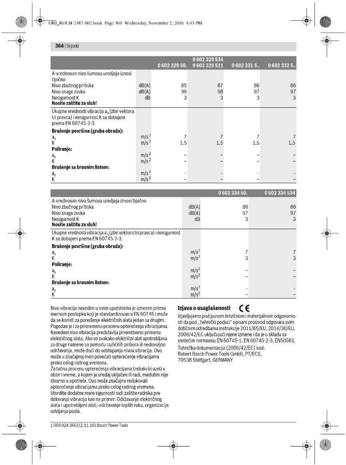

OBI_BUCH-2487-002.book Page 365 Wednesday, November 2, 2016 4:43 PM
Srpski 365
Henk Becker
Executive Vice President Engineering
Heimut Heinzelmann
Head of Product Certification PT/ECS

Robert Bosch Power Tools GmbH
70538 Stuttgart,GERMANY
Stuttgart, 01.01.2017
Montaža
Montaža zašitihn uredjaja
Opsta uputstva
Prekinite snabdevanje energijom pre Ngo sto prudzmede podesavanje uredija, zamenjujete delove pribora ili ostavljate elektrki uredaj. Ova mera opreza sprečava slucjan start elektricnog alata.
Uputstvo: Posle loma brusne ploce za vreme rada il pri ostecenju prihvatnog uredja na zaftinoj haubi/elektrinom alatu, mora se elektrcni alat hitno poslatu u servis, adrese pogledaje u odeliku ,Servisna sluzba i savetovanje o upotrebi*.
Podesite zastîte haube tako, da bude sprećenoletenje varnica u pravcu radniki.
Upstvo: Kodniispusti na zaistnim haubama osiguravaju da se moze montirati samo zaistna hauba koja odgovara elektronicn alatu.
Zastitna hauba za bruşenje (pogledajte sliku A)
Vazi za sledece tipove:
-060230440
-06023295..
-0602324434
-06023315
-060232444.
-06023325..
-0602324464
-06023345..
-0602324474
-
Zaatittnu haabu 6 kodirnir bregom 8 stavlajte u kodiri
zleb na wratu vretena 4 dok snap zaatiti haube ne
nasedne na prurubnic elektricng alata. -
Prilagodite poziciju zašitne haube zahtevima radnog koraka.
-
Radi ogurjanza zastithe nae bateginite fiksni zavrtan7 J na zatezi obrtn moment oad on majianee 10 Nm.
OBI_BUCH-2487-002.book Page 367 Wednesday, November 2, 2016 4:43 PM
Srpski|367
posedno u vezi sa dodatnim materijama za obradu dvrte (hromati, zaistna sredstva za drvo). Materijal koji sadrjiz abzebst smeju raditi sono smo strucnajci.
-Koristite sTo jevieme moguce uisavanje praseine pogodna za material.
Pobrinite se za dobro provetravanje radnog mesta.
- Preporucje se, da se nosi zašitna maska za disanje sa klasom filtera P2.
OBI_BUCH-2487-002.book Page 377 Wednesday, November 2, 2016 4:43 PM
Slovensko 377
| Visokofrekvenčni kotni brusilnik | ||||
| Zašćitni razred | ©/I/I/I/I | © | © | © |
| Vrsta zašće | IP 20 | IP 20 | IP 20 | IP 20 |
Oporozilaprioskrbizel.energijo
Elektric no orodje je del visokofrekvenegaistema in potrebuje 3-fazri tok s frekvenco v skladu z navesbarni na tipski tablici.
Da bi dosegli navedeno frekvenco, morate elektricno orodje povezati s frekvencnim pretvornkom (glejte, Prikljucitev na oskrbovanje z el. energio", stran 381).
OBI_BUCH-2487-002.book Page 378 Wednesday, November 2, 2016 4:43 PM
378 | Slovensko
| 0 602 329 50. | 0 602 329 534 | 0 602 331 5.. | 0 602 332 5.. | ||
| 0 602 329 511 | |||||
| Nivo hrupa naprave po vrednotenju Aznaša tipićno | |||||
| Nivo zvočnega tlaka | dB(A) | 85 | 87 | 86 | 86 |
| Nivo jakosti zvoka | dB(A) | 96 | 98 | 97 | 97 |
| Netočnost K | dB | 3 | 3 | 3 | 3 |
| Nosite začitne glušnike! | |||||
| Skupne vrednosti vibracij a, (vektorska vsota treh smeri) in negotovost K se izraču-najo v skladu z EN 607 45-2-3. | |||||
| Bruşanje prevlek (kosmačenje): | |||||
| a, | m/s2 | 7 | 7 | 7 | 7 |
| K | m/s2 | 1,5 | 1,5 | 1,5 | 1,5 |
| Poliranje: | |||||
| a, | m/s2 | - | - | - | - |
| K | m/s2 | - | - | - | - |
| Bruşanje z brusilnim listom: | |||||
| a, | m/s2 | - | - | - | - |
| K | m/s2 | - | - | - | - |
| 0 602 334 50. | 0 602 334 534 | ||
| Nivo hrupa naprave po vrednotenju A znaša tipićno | |||
| Nivo zvočnega tlaka | dB(A) | 86 | 86 |
| Nivo jakosti zvoka | dB(A) | 97 | 97 |
| Netočnost K | dB | 3 | 3 |
| Nosite zaščitne glušnike! | |||
| Skupne vrednosti vibracij a, (vektorska vsota treh smeri) in negotovost K se izračunoj v skladu z EN 60745-2-3. | |||
| Bruşanje prevlek (kosmačanje): | |||
| a1 | m/s2 | 7 | 7 |
| K | m/s2 | 3 | 3 |
| Poliranje: | |||
| a1 | m/s2 | - | - |
| K | m/s2 | - | - |
| Bruşanje z brusilnim listom: | |||
| a1 | m/s2 | - | - |
| K | m/s2 | - | - |
OBI_BUCH-2487-002.book Page 379 Wednesday, November 2, 2016 4:43 PM
Slovensko 379
Henk Becker
Executive Vice President Engineering
Heimut Heinzelmann
Head of Product Certification PT/ECS

Robert Bosch Power Tools GmbH
70538 Stuttgart,GERMANY Stuttgart, 01.01.2017
Montaža
Montaža zašcitnih priprav
Splośna navodila
Pred nastavitvjo naprave, zamenjavo delov pribora ali preden odlozite elektricno orodje, morate prekiniti oskrbo z energijo. Ta previdnostni urek opemogoca ne-nameren zagon elektrica negoia.
Opozorilo: Po Iomu brusilene kolta med obrotovanjem ali pri poskodovanju prijemal na začitnemPokrovu/na elektrínekornodoj, morate elektríne oro nadje takojal posnat na naslov servisi; naslov se nahajao v odstavku, Servis in svetovanje o uparobi";
Nastavite zašitne pokrovec tako, da se prepreci letjenie isker v smer posluzevaica.
OBI_BUCH-2487-002.book Page 382 Wednesday, November 2, 2016 4:43 PM
382 | Slovensko
Vklop/izklop elektricna orodja
z varnostnim pomicim pretikalom (gleje sliko J1)
OBI_BUCH-2487-002.book Page 387 Wednesday, November 2, 2016 4:43 PM
Hrvatski387
OBI_BUCH-2487-002.book Page 391 Wednesday, November 2, 2016 4:43 PM
Hrvatski|391
Napomene za elektricno napajanje
Elektrichi alat je dio visokofrekventnog sustava i za njegov rad je potrebna trofazna struja sa frekvencijom prema tipskoj ploci.
Dabise postigova frekvenocija, elektrichia atse mora spojiti a s prelatvaracem frekvencije (vidjeti 巧 Prikljucak na izvor strjue, strania 394).
Informacije o bucici vibracijama
OBI_BUCH-2487-002.book Page 392 Wednesday, November 2, 2016 4:43 PM
392|Hryatski
| 0.60232950. | 0.6023295340.602329511 | 0.6023315.. | 0.6023325.. | |
| Ukupne vrijednosti vibracija a1 (vektoriski zbor u tri smjera) i nesigurnost K odredeni su prema EN 60745-2-3. | ||||
| Bruşenje povrsina (gruba obrada): | ||||
| a1 | m/s2 | 7 | 7 | 7 |
| K | m/s2 | 1,5 | 1,5 | 1,5 |
| Poliranje: | ||||
| a1 | m/s2 | - | - | - |
| K | m/s2 | - | - | - |
| Bruşenje sa brusnim listom: | ||||
| a1 | m/s2 | - | - | - |
| K | m/s2 | - | - | - |
| 0 602 334 50. | 0 602 334 534 | ||
| Prag buke uredaja vrednovan sa A obično iznosi | |||
| Prag zvučnog tlaka | dB(A) | 86 | 86 |
| Prag učinka buke | dB(A) | 97 | 97 |
| Nesigurnost K | dB | 3 | 3 |
| Nosititišnike za sluh! | |||
| Ukupne vrijedosti vibracija a1(vektorski zbor u tri smjera) i nesi-gurnost K odredeni su prema EN 60745-2-3. | |||
| Bruşanje povrsina (gruba obrada): | |||
| a1 | m/s2 | 7 | 7 |
| K | m/s2 | 3 | 3 |
| Poliranje: | |||
| a1 | m/s2 | - | - |
| K | m/s2 | - | - |
| Bruşanje sa brusnim listom: | |||
| a1 | m/s2 | - | - |
| K | m/s2 | - | - |
Henk Becker
Executive Vice President Engineering
Helmut Heinzelmann
Head of Product Certification
PT/ECS

iV. k = m _____
Robert Bosch Power Tools GmbH 70538 Stuttgart, GERMANY Stuttgart, 01.01.2017
Montaža
Montaža zašitnih naprava
Opé napomene
OBI_BUCH-2487-002.book Page 394 Wednesday, November 2, 2016 4:43 PM
394|Hrvatski
Tipku za utvrdivanje vretena pritsinite samo dok brusno vreteno miruju. Elektricni alat bi se inace mogao ostetiti.
- Prije ugradnjé brusnog alata pritsinite tipku za utvrdivanje brusnog vretena 5 za blokiranje brusnog vretena 3 i drzite tipku pritsputu.
-Montiraje trazeni brusni alat (vidjetji Mntaza za brunsejene, rezanje il grubo adrurov, stranica 393).
- Otpistute tipka za blokiranje vretena 5 za oslobadanje blokade brusnog vretena.
Montaza gumenog brusnog tanjura (vidjeti siku F)
Uldised ohutusjuhised
TAHELEPANU Koik ohtusnoued ja juhised tuleb labi lugeda. Ohtusnuete ja juhiste eirame tagajareks voib oila elektriloo, tulekahju ja/voi rasked vigastused.
OBI_BUCH-2487-002.book Page 401 Wednesday, November 2, 2016 4:43 PM
Eesti 401
OBI_BUCH-2487-002.book Page 405 Wednesday, November 2, 2016 4:43 PM
Eesti 405
| 0.60230140. | 0.602301434. | 0.60230440. | 0.60230540. | |
| Vibratsionitase \( a_{\mathrm {p}} \) (kolme telje vektorsum- ma) ja mõötemääramatus K, kindlaks teh- tud kooskolas standardiga EN 60745-2-3. | ||||
| Pinna lihvinmisel: | ||||
| \( a_{\mathrm {n}} \) | \( m/s^{2} \) | - | 5,3 | 5 |
| K | \( m/s^{2} \) | - | 2 | 2 |
| Poleerimisel: | ||||
| \( a_{\mathrm {n}} \) | \( m/s^{2} \) | 3 | 3 | - |
| K | \( m/s^{2} \) | 1,5 | 1,5 | - |
| Lihvaberiga lihvinmisel: | ||||
| \( a_{\mathrm {n}} \) | \( m/s^{2} \) | 3 | 3 | - |
| K | \( m/s^{2} \) | 1,5 | 1,5 | - |
OBI_BUCH-2487-002.book Page 406 Wednesday, November 2, 2016 4:43 PM
406|Eesli
Henk Becker Helmut Heinzelmann Executive Vice President Head of Product Certification Engineering PT/ECS

iV. k = m
Robert Bosch Power Tools GmbH
70538 Stuttgart, GERMANY
Stuttgart, 01.01.2017
Montaž
OBI_BUCH-2487-002.book Page 407 Wednesday, November 2, 2016 4:43 PM
Eesti 407
OBI_BUCH-2487-002.book Page 408 Wednesday, November 2, 2016 4:43 PM
408|Eesti
Eemaldamine
OBI_BUCH-2487-002.book Page 409 Wednesday, November 2, 2016 4:43 PM
Eesti 409
OBI_BUCH-2487-002.book Page 410 Wednesday, November 2, 2016 4:43 PM
410|Eesti
Staatikaalased juhised
Soonte loikamisel kandvatesse seintesses tuleb juhindusa standardi DIN 1053 1. osast voi vastva riigi seadustest. Neid eeskirj uulet bingimata jargda. Enne to alustamist pida gndou padeva staatikaspetsialisi, arhitekti vto dejuha talajaga.
Lihvimine
OBI_BUCH-2487-002.book Page 413 Wednesday, November 2, 2016 4:43 PM
Latwiesu|413
Darbinstrumentu arejam diametram un biezumam jaatbilst elektroninstrumenta konstrukcijai un izermi. Ja darbinstrumenta izmeri ir izveleti nepareizi, tas pilniba nenovietojas zem aizsargarse un darba laika apgrutina instrumenta vadibu.
Darbinstrumentiem, kas stiprinami ar vitnes palidzibu, stiproinosajai vitnei precizi Jaatbilst silpmañas darb-varpstas vitnei. Darbinstrumenti, kas stiprinami ar balstpaplaksnes palidzibu, atveruma diametram Jaat-bilst balspaplaksnes stiproinsa paceluma diametram. Darbinstrumenti, kas nav precizi nostipinati uz elektroninstrumenta darbwpstas, neviemneri griezas, loti specigi vibre un var izaisit kontroles zaude sanu pár elektroninstrumentu.
Neizmantojiet bojatus darbinstrument. Ik reizipirms darbinstrumentu lietofoanas parbaudit, vai tie nav bojati, plemeram, vai stipesanas diski nav atslaojuies vaieplaisajui, vai shpeanas pamatn nav vrojamas plagias un vai stipeu sukua veidojojas stieplies nav vajgas vai athuzas. Ja elektroninstrumentes vai darbinstruments ir kritis no zinima augstauna, pirbaudit, vaitas nav bojats, vai ar izmantojiet darbam nebojatu darbinstrumentu. Pec darbinstrumenta apskates un lestipriinaas laujiet elektroninstrumentam darbotes ar maksimalo griesanas atrumu vienu minuti ilgi, turo rotejoaso darbinstrumentu drosa attaluma no sevis uncitam tuvuma esosajam personam. Bojatie darbinstrumenti sadas parbaudes laika parasti salust.
Lietojet individuos darba aizsardzbas lidzeklus. Atkarba no veicaan darba rakstura izvelleties pilu sejas aizsargu, nosledosas aizsargrilres va parastas aizsargrilles. Lai aizsargatos no lidojsajam slipanas darbinstrumenta un apstradjama materiala da liuam,poc vajadzbas lietojet puteku aizsargmaska, ausu aizsargus un aizsargcimdu var anipasu preksautu. Lietotaja acis japaesra no lidojsajlem svekermeniem, kas dazkart rods darba gaita. Puteku aizsargmaskai var respiratorum japaagsa letotaja elpoanas celni no putekjlem, kas veidojas darba laika. Ilgsto airodoties stipra trokspa lespaida, var rasties paliekososi zdirtes traucejumi.
Sekojiet, la citas personas atrasos drosa attaluma no darba vietas. Ikvienam, kas atroidas darba vietas tuvmu jalieto individuale darba izasardzibas lidzeki. Apstradajama prieksmeta atluzas val saluzsa darbinstrumenta dalas var lidot ar ieverojuamu atrumu un nodarit kaitejumu cilveku veselbai ai ereverojama attaluma no darba vietas.
Darba laika turiet elektroninstrumentu tikai aiz izola-tamvirsmam, joa tseiprinatais darbinstruments var skart sleptus elektriskos vad vua paasa instrumenta elektrokabeli. Darbinstrumentam skarot spiregumnesosus vad, spiregums nonak ar uz instrumenta meta daadam un var but par celoni elektriskajam triecianam.
Netuviniet rotejosdarbinstrumente elektrokabelim. Zudot kontrolei par instrumentu, darbinstruments var pargriezt kabeli vai iekerties taja, ka rezultata kada nolietotaja kermena这方面 var saskarties ar rotejoso darbinstrumentu.
Nenovietojet elektroinstrumentu, kamar taj iestipri-naits darbinstruments nav pilinigl apstijes. Rotejoais darbinstruments var skart atbalsta virsmu, ka reztată elektronintemars var klut nevadamis.
Nedarbiniet elektroninstrumentu laika, kad tas tick parviotets. Lietotaja apgerbs vai mali var nejausi nonakt saskar er rotejo so darbinstrumentu un ienkerties taja, izraisot darbinstrumenta saskaransos ar letotaj kermeni.
Regulari tiet elektroninstrumenta ventilacijas atveres. Dzineju ventilejosa gaisa plisma ievkel puteklus instrumenta korpusa, bet liela metala puteklu daudzuma uzkrasanas var but par celoni elektrontrauma!.
Nelietojiet elektroinstrumentu ugunsnedrosu materi-lu tuvuma. Lidoosas dzirksteles var izraisit sadumaterialu alzdeganos.
Nelietojetj darbinementus, kuriemiipievada dzesejosalsikidrums.Udens vaitu skidro dzesezanas lidzeki uzimantosana var but par celoni elektriskajam triecianam.
Atsitiens un ar to saistitie noradijumi
Atsitiens ir specifiksa instrumenta reakcija, peksn iekeroties vai iestregst rotejosam darbinstrumentam, piemeram, slipsanas diskam, slipsanas pamatnei, stieplu sukai u. t. t. Retejosa darbinstrumenta iekersanas vai iestregsana izraisa tpeknsu apstasanos. Ta rezultata elektronstrements parvietogas virziena, kas pretejs darbinstrumenta kustibas virzianem iestreguma viet, un nereti klust nevadams. Ja, piemera, slipsanas disks iekeras vai iestregst apstradajama prieksmeta, taja tegremdetä diska mala var izrauties no apstradajama materialia vai izraisit atsienu. Sada gadijumla slipsanas disks parvietojas lietotaja virizna vaari prom no vinja, atkariba no diska rotacjas virziana atticibra pret apstradajamo prieksmetu. Turklat slipsanas disks var saluzt.
Alsitiens ir sekas elektroninstrumenta nepareizai vai neprasmigai lietosanai. No tā var izavirities, ieverojot zinamus pie-sardzibas pasakumus, kas aprakstiti turpmakaja izklasta.
Stingri turiet elektrinstrumentu un ienemiet tdu kermena un roku stavokil, kas vislabak paui pretoties atsitienta spekam. Vienner Izmantojt papidrokturi, kas lauj optimali kompenset atsitienu vai reaktvo griezes momentu un saglabat kontroli par instrumentu. Velicot zinamus piesardzibas pasakumus, lietotajs jebkura situaci ja spelj efektvi pretoties atsitienam un reaktivajam griezes momentam.
Netuviniet rokas rotejošam darbinstrumentam. Atsiti-na gadijumá darbinstruments var skart ari lietotája roku.
Izvairieties atrasties vieta, kurp varetu parviotietes elektronuments atstiena brid. Atsitiena brid elktrainstruments parvirotojas virziana, kas pretejs darbinstrumenta kustibas virzianam lestrugma vieta.
Levojiet ipasu piesardzbu, stradajot stiru un asumalu tuvum. Nepiejauijet, laDarbinstruments atlektu no apstradjama pireksmata via iestregtu taja. Sarakoties ar sturiem vai asam malam, rotejoals darbinstruments izliecas an attec no apstradjama pireksmata via iestregst taja. Tas var but par celoni kontroles zaudeisanai par elektroninstrumentu vai atsitienam.


414|Latviešu
Nelietojietzagaasmenus,kasapgadatarzobiem.Sadu darbinstrumentuzmanto'sana var but par celoni atsitien namv Kontroles zauedesani par elektroninstrumentu.
Ipaise droisibas noteikumi, veicot slipesanu un griesanu
Lietojet vienigi jusu riciba eosəsjam elektroninstrumentam piemeroitus slipesanas darbinstrumentus un sadiem darbinstrumente paredzetu aizsargparsegu. Aizsargparsegs var nepietiekami nosegt nepiemeroitus slipesanas darbinstrumentus, lidar to nejauot panakt velamo darba drobroj.
Izliektie slipiski jäestiprina tā, lai to slipvirma neizvirzitos pārā azsargpärsega malai. Nepareizi istripinats slipdisks, kas izvizras pāri aizsargpärsega malai, nevar tikt pietiekoso而这e nosegts.
Drośfas apsvērumu déi aizsargpārsegam jabt stingri nostipinīṭām už elektroinstrumenta un noregūlēṭam tā, lāl lietotāja virziena būt vērsta péc lespejas mazáka slipsēsanas darbinstrumenta nenoşete dāla. Aizsargpārsegs palidz aizsargl lietotaju no atilizam un nejaušas saskarṣanās ar silēsanas darbinstrumentu, kā ri no lidošām dirzkilestem, kas var āziedzindat Āperbu.
- Slipesanas darbinstrumentu drikst izmanton vienigi tādā veidā, kādam tas ir paredzets. Piemērām, nekad neizmantonjiet griesanas diska sānu virsūm sulipesanai. Griesanas disks ir paredzets materiālu apstradei ar malas grieżějskautni. Stilpris spiediens sānu virziena var salauzt so darbinstrumentu.
Kopa ar izteo silpeñas disku izmantojet vienignebojatu piispiejezgriezni ar plemotrof ur im zemriem. Piemero tia piesta piéspiejezgrieznis darba laika drosi balsta silpeñas disku un sanamiza ta salusanas iepeju. Kopa ar griesnas diskiem izmantojamie piesspiejezgrnviar atskirties no piéspiejezgrgniam, kas lietomapi Kopa ar citu veidu silpeñas diskiem.
Neizmantojet nolietotu slipesanas diskus, kas padezeti lielakas jaudas elektroninstrumentiem. Lieliem elektroninstrumentiem paredzete slipesanas diski nav pemeroti darbam mazakos elektroninstrumentos, kuru griesa nas atrums parasti ir lielaks, un tapetie darba laika var sa luizt.
Citi ipasie droshbas noteikumi,veicot griesanu
Neizdariet park liel spiedenu uz griejanas disku un nepieaujieta iestregsanu.Neveidojet parak dzilus griezumps.Parlogojot griejanas disku,tasbieikeras via iestregst griezuma,un lidar to pieaug ari atsitena vai darinstrumenta salusanas iespeja.
Izvalrieties atrasties rotejosa griesanas diska prieksa vai aiz ta. Ja darba laika lietotajs parvietro griesanas disku prom no sevis apstradama grieksmeta virziena, tad atsi tiana gadija melektoinstruments ar rotejosu griesanas disku tikis sviests tiess lietotaja virziena.
Partraucot darbu vai lestrgstot griesanas diskam, Izsledziet elektroninstrumentu un turiet to nekustige, lidz griesanas disks plinji apstasj. Nemeginti izvilk't no griezuma vel rotejos griesanas disku, jo sada darbiba var but par celoni atsitienam. Noskaidrojet un noversiet diska lestrgstan celoni.
Neiesledziet elektroninstrumentu no jauna, ja taja iestiprinatais darbinstruments atroides griezuma vieta. Pec ieslaganas nogaidiet, lidz darbinstruments sasniedz plnu griesanastrum, un tikai tad uzmaniigurpiniet griesanu. Preteja gadijma griesana disks variekerties griezumaviazilekt no ta, k airi var noitki atsi- tiens.
Lai smazinatu atsitiena risku, iestregstot griesanas diskam, atbalsitegriezama materiala loksnes va lileia izmera apstradajamos priekmetus. Lieli prieksmetivar saliekties paisi savra iespaida. Apstradajamas prieksmets jaatbalsta abas pesues-gan griezuma tuvuma, gan ari prieksmeta ala.
levorejiotipa'spiesardzibu,veidjoot padzilinajumus sienas vaitojectoikos,kasnavaplukojami noabpusem.legremdejot griesanas diskutmaterialia,tasvar skart gazes vad,uendsvadu,elektroparvadeslinju vaitcitu objektu,ka Sawukart var izraisit atsitien un/vai but par celoni savainojumam.
ipasidrosihasnotekumi,veicot slipesan ar smllsapira Ioksn
Neizmantojiet Ielaka Izmera slipkonses, Izvelleties darbam slipkonses ar izmerie, kon roadijusi raziotaj-firma. Ja slipkonses sniedzas pari slipesanas pamatnes malam, tas var but par celoni savainojumam, izsaukt slip-kloksnes iestregsanu val piisanu, ka an izrasit atsitienu.
Ipaie drośibas noteikumi, veicot pulešanu
- Neatstajet nenostiprinatas pulejoša uziktna dalas, ipaši tā stiprinošas atsaites. Atpinitn un sasanienit vai saisainit stiprinošas atsaites. Nenostiprinatas, kopa ar uzktni rotejošas stiprinošas atsaites var skart lietotaja rokas an aptitudes apirkstiem vai kekerties apstradajamaja priekšmetá.
ipasie droibas noteikumi,veicot apstradi ar stiepluku
Sekojiet, lai darba laikä stiepu sukai neizkristu vai nenoluztu atseviskas stieplies. Naparslogojiet sukas stieplies, stipri spižot uz to. Noluzsas stieplies lido ar lielu atrumu un var loti viegli izkut caur planu apgerbu vaimatiem.
丨 Izmantojoi aizarsgparsegu, nepielauijiet ta saskaransanos ar stieplu sukau. Kausveida un diskveida stieplukam spiediana un centbodzes speka iespaia var paliinaties diamets.
Papildurošibas noteikumi

Nesajiet aizsargbrilles.
Lietojot piemerotu metalmekletaju, pausbaudit, vai apstrades vietu neskeros sleptas komunalapdges linjias, vai ar grieziedies pec konsultacijas vietja komunanas saimmiecibas iestade. Darbinstrumenta saskarsanar elkertarpavdes linju var izraisi azdegsanos vai but par celoni elektrskajam triecienam. Bojajums gazes pavrdes linjia var izraisi spradzienu. Darbinstrumentam


Latviesu|415
skarot udensvada cauruli, var tikt bojatas materiolas vertibas, kari stradajossa persona var sanemt elektrisko trieciu.
Elektrobaroanas partraukuma gadijumai,piemeram, ja teik partraukta sprigema padeve elektronikla vait vienotakontaktdaksa,abrvoijetElektroninstrumenta esledzju un parviietojiet to stavokil,izslegtsT. Ta tiek noversta elektroninstrumenta nekontroleta,palvaliga ie-sleganas.
Piers tie na atzusisi. Darba laik diaki stipri sakarist.
Darba laika stinggi turiet elektroinstrumentu ar abam rokam un centieltes leturet dreu staju. Elektroinstrumentu ir drosak vadit ar abam rokam.
Nostipriniet apsstradajamo pirekmetu.lestiprinot apstradajamo pirekmetu skruvspilis vai cita stiprinajuma icere, stradat ir dorosak, neka tad, ja tas teck turets arrokam.
Pievienojet elektroninstrumentu tikai tadam elektrtoklam, kas agpādās ar efektiv aizsargzemējumu. Elektrotkla kontaktigdzad un paagarinatajkabelim jabut drosi savenotiem ar pareizi Funktionējsoa izasargzemējuma kédi.
Drosibas noteikumi augstfrekvences elektroinstrumentu elektrarosanai
Stingri leverojiet frekvens parveidotaja drosihas noteikumus un lietoisanas noradijumus! Siku k informaciju var sanem't no frekvens parveidotaja ražotaj.
Lietojot frekvences pärveidotäju apstaklós, kur jänodrosina pastiprinată personu aizardziba, tas japievieno elektrotiklam carun nopilónds strávas izasargreleju. Pastiprinată personu aizardziba ir janodrosina, pieméram, tad, ja darbs notiek mitrás telpás vai tiek apstradi tād materiali, no kurim apstrades gaita izdalās stravu vadoš utpekli. Atteiksanás no nopilónds strávas izasargierici izmantoşanas var küt pracelōn elektriskajam triecianam, izraistai idægaznosi vai radit napjetnu savainojumov.
Noplides strvas aizsargiericu pievienosanu barojsa jam elektroklam dirkst uzticet tikai kvalificetam personalam. Tikai tiesjams nodrosinat aizsargiericu nevainjoam fungcioneesanu.
Frekvences parveidotajia izejas spriegumam un frev ecei jaatbilst vertibam, kas noraditas uz augsfrekvences elektroninstrumenta markejuma plaksnites.
Lietojot elektroninstrumentu, tam jabut apgadatem ar piemerotou kontaktdaksu.CEE kontaktdaksaj jasej no droinat elektroninstrumentu nepiecijsamo nominalo stravu (skafit sadalu, Tehniskie parametri).
Kontaktdaksas montaza un pievienosana barojsajam elektrotiklam javeic kvalificetam personalam, kas ir apmacits darbam ar augstfrekvences elektroinstrumentem un icéricem.
丨 Izmantojiet vienigi originai savienojoso kabel! Ik reizi pirms lietoisanas paibaudiet, vai nav bojats elektroninstrumentes, tavienojosais kabelis vai kontaktdksa. Lai izvairitos no negadijumiem, bojato savienojoso kabeli un kontaktdksa sedrifikst remontet, bet tie ir jannomaia.
Izstradajuma un ta daribas apraksts

Uzmanigi izlasiet visus drosibas noteku-mus. Seit smigo drosibas notekumu un nora dijumu neieveroana var izraisit azdeganos un but par celoni elektriskajam triecienam vai nipietnam savainojumam.
Ludzam atvert atlokamo lappusi ar elektroinstrumenta attelu un turet to atyertu visu laiku, kamir tiek lasita lietosanas pa-macibia.
Pielietojums
Instrumentiem:
-06023014..
060230540
-0602306434
-060232440.
Elektroinstruments ir paredzets meta-la lakotu virsumslipeisanai ar smilspapiru un pulesanai, nelietoj etudjoi
Instrumentiem:
-060230440
-060232444...464...474...434
-06023295.
-06023315..
-06023325..
-06023345..
Elektroinstruments ir paredzets metăa un akmens griesanari, rupjai slipësanai un apstradei ar stieplu sukui, neliietojot udenei.
Veicot griesanu ar kompozitajem slipesanas darbinstrumentiem, jaielo specials griesanas aizsargparsegs.
Veiot akmens griesanu, jänodrosina pietiekosa puteku uzuksana.
Derigi visu tipu elektroninstrumentiem
Kopa ar So elektochninstrumentu drikst izmantoit vienigi tadinu aizsargparsegus un piespiedjejuzgrieznus, kas ir piegadati vai ieteikti izmantośanai kappa ar to.
Attelotas sastavdalas
Atteletó sastádvúo numerculación aíbitl numuriem elektrininstrumenta atéla, sa kniags ilustrativjá lappuse.
1 lesledzweis
2 Papildrokturis
3 Darbwaernst
4 Darbyarpstas aptvere
5 Taustin's darbyarpstas fiksesanai
6 Aizsargparsing
7 Skruwe aizsargparsega stiprinaisanai
8lerobejoosaisizcilnis
9 Rokuaizsargs
10 Balstpaplaksne ar O veida gredzenu
11 Slipesanas/griesanas/rupjas slipsanas disks
12 Piespiedehyzgrieznis
13 Divizilnu uzgrieznu atslega
14 Valejia tipa atslega ar platumu 17 mm
15 Apalais uzgrieznis


Uzmanigi Izlasiet visus drobis notablekumus. Seit nsiegtro drobis notablekumu un nora dijumu neieverošana var izrasit azdegsanos un butp aceloni elektriskajam triecienam vai nopjetnam savainojumam.
Ludzam atvert atlokamo lappusi ar elektroinstrumenta attelu un turét to atyertu visu laiku, kamir tiek lasita lietosanas pa-máčija.


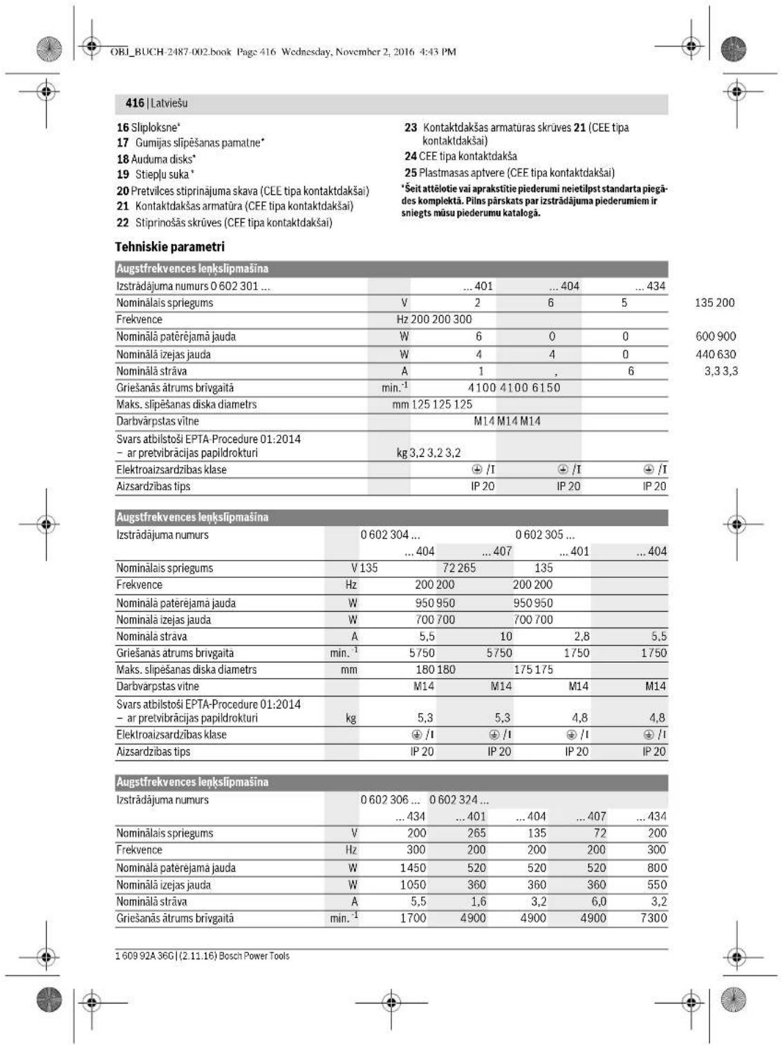
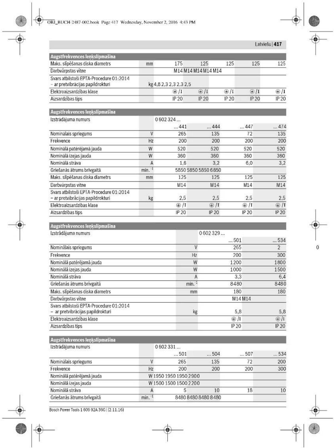

OBI_BUCH-2487-002.book Page 418 Wednesday, November 2, 2016 4:43 PM
418|Latviešu
| Augstkrevnesc lenkslipmasina | ||||
| Maks. slipesanas diska diameters | mm 180 180 180 180 | |||
| Darbvärpstas vitne | M14 M14 M14 M14 | |||
| Svars atbilstoši EPTA-Procedure 01:2014 - ar pretvibracijas papildrokturi | kg 7,1 7,1 7,1 7,1 | |||
| Elektroaizsardžibas klase | ⊕ /1/1/1 | ⊕ | ⊕ | ⊕ |
| Aizsardžibas tips | IP 20 | IP 20 | IP 20 | IP 20 |
Augstfrekvences lenkslipmasina
| Izstradajuma numurs | 0 602 332 ... | |||||
| ... 501 | ... 504 | ... 507 | ... 534 | ... 511 | ||
| Nominálais spriegums | V 265 135 72 200 72 | |||||
| Frekveance | Hz 200 200 200 300 300 | |||||
| Nominálá paterejama jauda | W | 1950 | 1950 | 1950 | 2900 | 2900 |
| Nominálá izejas jauda | W | 1500 | 1500 | 1500 | 2200 | 2200 |
| Nominálá strava | A | 5 | 10 | 18 | 10 | 27 |
| Grieşanás átrums brivgaita | min. -1 | 6600 | 6600 | 6600 | 6600 | 6600 |
| Maks. slipşanas diska diametris | mm 230 230 230 230 230 | |||||
| Darbvarpstairs vitne | M14 | M14 | M14 | M14 | M14 | |
| Svars atbilostoji EPTA-Procedure 01:2014 - ar pretvibracjas papildrokturi | kg | 7,1 | 7,1 | 7,1 | 7,1 | 7,1 |
| Elektroaizsardzibas klase | ± /T | ± /T | ± /T | ± /T | ± /T | |
| Aizsardzibas tips | IP 20 | IP 20 | IP 20 | IP 20 | IP 20 | |
Augstfrekvences lenkslipmasina
| Izsträdajuma numurs | 0 602 334 ... | ||||
| ... 501 | ... 504 | ... 507 | ... 534 | ||
| Nominălais spriegums | V 265 135 | 72 200 | |||
| Frekcvence | Hz 200 200 200 300 | ||||
| Nominăl paterejama jauda | W | 2500 | 2500 | 2500 | 3800 |
| Nominăl izejas jauda | W | 2200 | 2200 | 2200 | 3100 |
| Nominăl strava | A | 6,7 | 13,2 | 24,7 | 13,2 |
| Grieşanás átrums brivgaită | min. | 6600 | 6600 | 6600 | 6600 |
| Maks. sifeşanas diska diametris | mm 230 230 230 230 | ||||
| Darbvärpstas vitne | M14 M14 M14 M14 | ||||
| Svars atbilostosi EPTA-Procedure 01:2014 | |||||
| - ar pretvibracijas papildrokturi | kg 7,8 7,8 7,8 7,8 | ||||
| Elektroaizsardžibas klase | €/1/1/1 | € | € | € | |
| Aizsardžibas tips | IP 20 | IP 20 | IP 20 | IP 20 | |
Noradijumi atticibā uz elektrobarosanu
Elektroinstruments ir dala no augstfrevences elektrobarosanasistemas, un ta darbinasanair nepieiesams trijazumainsprigums ar frekvci, kuras vertiba ir noradita uz markejuma plaksnites.
Lai igulu spiregumu arSadu frekvenci, elektroninstruments japevieno frekovncarpevidotajam (skatit sadalu "Pievienosana elekrotiklam" lappuse 423).
1609 92A 36G| (2.11.16) Bosch Power Tools


OBI_BUCH-2487-002.book Page 419 Wednesday, November 2, 2016 4:43 PM
Latviešu|419
OBI_BUCH-2487-002.book Page 420 Wednesday, November 2, 2016 4:43 PM
| 420 | Latviešu | |||||
| 0.602 329 50. | 0.602 329 5340.602 329 511 | 0.602 331 5.. | 0.602 332 5.. | ||
| Kopějá vibracijas pažtrinajuma věříba a.(vektoru summa trijos virzienos) unizkliédeK ir noteikta atbilstoši standartamEN 60745 2-3. | |||||
| Vírsmu silpěsana (rupjá): | |||||
| a, m/s2 | 7 | 7 | 7 | 7 | |
| K m/s2 | 1,5 | 1,5 | 1,5 | 1,5 | |
| Pulësana: | |||||
| a, m/s2 | - | - | - | - | |
| K m/s2 | - | - | - | - | |
| Silpěsana ar silploksni: | |||||
| a, m/s2 | - | - | - | - | |
| K m/s2 | - | - | - | - | |
| 0 602 334 50. | 0 602 334 534 | |
| Instrumenta radità pèc raksturliknes A izsvertà trokṣa parametr tipiskās vertibas ir sādas: | ||
| skānas spiiedena limenis | dB(A) | 86 |
| skānas jaudas limenis | dB(A) | 97 |
| merijumu izkliede K | dB | 3 |
| Nēsājiet ausu aizsargus! | ||
| Kopejā vibrćijas pañtrinajuma vertiba a, (vektoru summa trijos virzienos) un izkliede K ir noteikta atbilostoši standartam EN 60745-2-3. | ||
| Virsmu slipësana (rupjā): | ||
| a1 | m/s2 | 7 |
| K | m/s2 | 3 |
| Pulešana: | ||
| a1 | m/s2 | - |
| K | m/s2 | - |
| Slipësana ar sliploksni: | ||
| a1 | m/s2 | - |
| K | m/s2 | - |
Sajamaciba noraditais vibracijas limenis ir izmerits atbilosti standarta EN 60745 noteiktajl procedural un var tik letots elektroinstrumentu savstarpjai salidzinasnai. To var izmanton ari vibracijas raditas papilud slodzes ieprieksejai noverteşanai.
Seit noraditas vibracijas limenis ir attiecinams uz elektroninstrumenta galvenajemi pielietojuma veidiem. Ja elektron-instruments tromie tiek izmanlots citi leiptiobotuma veidiem, kopa a citadiem piederumi vik kappa a atskirigemi darbinstrumentiem, ka ar tad, ja tas nav pietikoša apjoma apkalpots, instrumenta raditis vibracijas limenis var atskirtes no Seit noraditas vertibas. Tas var butiski paliellat vibracijas radito papidlu slodzi zinam darba laika posmam.
Lai preci zi yerétu vibricjas raditi papidu slodzi zināmam darba laika posmam, jæn ær vi aikis, kad elektroninstrumente ir izseglts vai ari darbojas, tácu faktišné tizmankots paredzêta darba veiksanai. Tas var butiski samazinī vibricjas raditi papidu slodzi zināmam darba laika posmam. Veiciet papidu pasakumus, lia paşagatu stradäjošo personu no vibricjas kaitigās iedaribbas, piernəm, savlaicigi velociet elektroninstrumente un darinstrumentu apkalpošanu, nové sriet roku atdžišanu un pareizi planoojet darbu.
Executive Vice President Engineering
Helmut Heinzelmann
Head of Product Certification PI/ECS

iV. k = m
Robert Bosch Power Tools GmbH
70538 Stuttgart,GERMANY
Stuttgart, 01.01.2017
1609 92A 36G| (2.11.16) Bosch Power Tools


OBI_BUCH-2487-002.book Page 421 Wednesday, November 2, 2016 4:43 PM

Montaža
Aizsargiericu dostiprinasana
Vispareji noradijumi
Pirms instrumenta regulestanas, piederumu nominas vai novietosanas paTRauCTam energijas padevi. Sads piesardzhas pasakms lauj noverst elektrinstrumenta nejau sieslegansos.
Piezime. Ja darba laika salust slipesanas disks vai tied bojata stiprinajuma ierie uz aizsargparsega vai uve elektroninstrumenta, elektron instruments nekavejoties janosuta uz tehniskas apkalposanicas iestadi, kuras adrese atrodama sadada,Klientu konsultaciu dinestiens un konsultacijas par lietošano'.
OBI_BUCH-2487-002.book Page 422 Wednesday, November 2, 2016 4:43 PM
422 | Latviešu
- Novietojet iuz darbvarposta vitnes piespiejdzgriemz 12 tai, lai centralais padzilinajams bultu verst ausgup.
- Stingri pieskrüveijet piespiejdējuzgriežn ar divizcilnu uzgriežnu atsleg 13, vienaicigi novietoj videotajia tipa uzgriežnu atsleg 14 u zipmasinas darbvarpststas noturplak nem un ar tás palidizbu turot darbvarpstst 3 nekustigi.
Iznem'sana
- Stingri turiet slipmasinas darbvarpstu 3 ar valejia tipa uzgrieznu atslegu 14, kas novietota uz darbvarpstns noturplaknem.
- Noskrüvejiet piesiedejuzgrézní 12 no slipmasinas darbvarpstates ar divizcijnu uzgréznu atselegu 13, vielaicigutrot slipmasinas darbvarpstu ar valejá tipa uzgréznu atselegu 14, kas novietola už tás noturplnám.
Tad nonemiet silpeanas darbinstrumentu un balstpaplak sni no lipmasinas darbyarpstas.
Elektroinstrumenti ar darbvarpstas fikseshanas taustinu 5
Instrumentiem:
-060232440.
-0602324434
-060232444
Lietojot elektroninstrumentus ar darbvarpstas fikseisanas taunipu 5, silpeisanas darbinstrumenta jestipiranaanas laika to darbvarpasta nav jatur nkustigi ar valeja tipa ugzieznu atsleg (atteI E1-E2.)
Nospiediet darvvarpst fiksakanas taustinu tikai laika, kad elektroninstrumenta darvvarpsta negriezas. Pretjaj gadijuma elektron instruments var tikt bojats.
Pirms slipesanas darbinstrumenta iestiprinasanas nospiediet darbarpsta fiksesanas taustiu 5, sadi fiksjeot elektrinstrumenta darvarpstu 3, un turiet taustiu nospiestu.
- lestiprierièt vélamo Slipēsanas darinstrumentu (skatit sa-dalu, "Slipēsanas, griesanas un rupjās Slipēsanas disku montàza" lappuse 421).
Lai abrivotu darbvarsptu, ataidiet darbvarpstas fiksësana taustiu 5.
Gumijas slipesanas pamatnes monta (attels F)
Instrumentlem:
-06023014. -060232440
-060230540.
-0602306434
-060230540.
-0602306434
lestiprinasana
- Nodrosiniet, laiz instrumenta buto nostiprinats roku aizsargs un papildrokturis (skatit sadalu „Aizsargieriču nostiprinása“ lappuse 421).
- Novietojet gumijas slipsjanas pamatni 17 uz slipmasinas darvarpastas 3.
- Novietojetil glipslokni 16 u guzmiji silpeisanas pamatnes.
- Novietojetil apalo uzgriznei 15 u ozdbarvaprastis vintnes.
Ar divizcijnu uzgrieznu atslegu 13 stingri pieskruveijet apa lo uzgriezni, vienlaicii novietoj valejia tipa uzgrieznu atslegu 14 uz slipmasinas darbvarpstates 3 noturplaknem un ar tas palidzibu turot darbvarsptu. - Nodrosiniet, laiz instrumenta buto nostiprinats roku aizsargs un papildrokturis (skatit sadalu „Aizsargieriču nostiprinása“ lappuse 421).
- Novietojet gumijas slipsjanas pamatni 17 uz slipmasinas darvarpastas 3.
Novietojiet sliploksni 16 uz gumijas slipesanas pamatnes.
Novietojiet apalo uzgriezni 15 uz darbvarpstas vitnes. - Ar divizcjnlu uzgieznu atslegu 13 stingri pieskruvejet apa lo uzgiezni, vienlaicigi novietoj valejia tipa uzgieznu atslegu 14 uz slipmasinas darbvarpstas 3 noturplaknem un ar tas palidziburo turot darbvarpstys.
Sekojet, lai apalais uzgieznis 15 pec pieskruvësanas pinnige ievietolos gumijes slipësanas pamalmes padzilëjumä, netracujet slopiësanas procesu un stingiri noturot silplokni.
Iznemşana
Stingri turiet slipmasinas darbvarpstu 3 ar vailejia tipa uzgrieznu atslegu 14, kas novietota uz darbvarpstas noturp Iakneh.
- Noskruejiet apalo uzgrezni 15 no slipmasinas darbvarps
tas ar divicilnzu ugrieznu atslegu 13, vienlaici turot slip
masinas darbvarspu ar lavejia lpa uzgrieznu atslegu 14,
kas noviota u tas noturplaknem.
- Tad nonemiet sliplopsni un gumijas slipesanas patamni no slipmasinas darbvarpstas.
Pulesanas audumripas montaza (attels G)
Instrumentiem:
-06023014. -060232440
-060230540.
-0602306434
lestiprinasana
Sekojit, lai pulešanas audumripinas vetne prezici abtišlu slipmasinas darbvarpstas vitei (M14).
Nodrosiniet, laiz instrumenta buteu nestiprinats roku aizsungs an papildrokturis (skatit sadalu_Aizsargiericu no stiprinasa" lappuse 421).
Uzskruvejet pulestanas audumripu 18 uz slipmasinas darbvarpstates 3 tik talu, latai ciesi piessiostos slipmasinas darbvarpstates noturplaknem, vienlaicignoturot darbvarpstu neukstige ar valej tipa uozgriezu atslegu 14, kas novietota uz slipmasinas darbvarpstates 3 noturplaknem.
Iznemşana
Noskruejeet stingri uzskruveto pulefasas audumripu 18 no silpmasinas darbvarpsst as valej tipa uzgrie2nu atslegu 14, kas novietota uz slipmasinas darbvarpsst 3 noturplaknem.
Stieplusukas montaza (attels H)
Instrumentiem:
-060230440. -06023315..
-060232444,...464, -06023325..
...474,..434 -06023345.
-06023295.
Iestiprinasa
Sekojet, lai stiepu sukas vitre precisez abilstu slifmason dasbarvastas vitrei (M14).
Nodrosiniet, lai uz instrumenta butu nopistirnats roku az sags un papildrokturis (skatit sadalu Aizsargieric nostiprinsana" lappuse 421).
Uzkruvejiet velamo stieplu sukuroskva deviskkevdusuku ulipmasinas darbvarpststik talai ciesi piesiestoslipmasinas darbvarpststotnaplknem, vienlaiciqnoturotdarbvarpstukneuksti arvalja tipuzgriezou atselegu14, kas novietota uzlipmasinas darbvarpststotnaplknem.
1609 92A 36G| (2.11.16) Bosch Power Tools

Gumijas slipesanas pamatnes montaza (attels F)
lestiprinasana


Latwiesu|423
Iznem'sana
- Noskrüvëjé tingriu uzskruët o steju suku 19 no slipmasinas darbvarpasta ar vaileja tipa uzgrieñyu atslegu 14, kas novietota uz slipmasinas darbvarpasta 3 noturplaknem.
Puteklu un skaidu uzuksan
Dazu materialiu, piemeraim, sinu saturou krasu, dazu koksnes skirmu, mineralu un metalu putekli var but kaitigi veselibai. Pieskarstanas sadiemi putekji var toiepošana var izraitsi alergiskas reakcijas var elpošanas celu salsimansu elektroninstrumenta lietotajam var darba vietai tuyma esojasn personaim.
OBI_BUCH-2487-002.book Page 426 Wednesday, November 2, 2016 4:43 PM
426|Lietuviskai
Piederumi
Lai pilna apjoma iepazitos ar Bosch augstas kvalitates papildpiederumu klasta, avariert interneta vietnes www.boschpt.com un www.boschproductiontools.com vai griezieties tukvakaj specializetaja tirdzniecibas vieta.
OBI_BUCH-2487-002.book Page 430 Wednesday, November 2, 2016 4:43 PM
430|Lietuviskai
OBI_BUCH-2487-002.book Page 433 Wednesday, November 2, 2016 4:43 PM
Lietuviškai 433
| Aukst dožnio kampinis šlifuoklis | |||||
| Gaminio numeris | 0 602 332 ... | ||||
| ... 501 | ... 504 | ... 507 | ... 534 | ... 511 | |
| Nominaloji Čatampa | V 265 135 72 200 72 | ||||
| Dažnis | Hz 200 200 200 300 300 | ||||
| Nominali naudojamoji galia | W 1950 1950 1950 2900 2900 | ||||
| Nominali atiduodamoji galia | W 1500 1500 1500 2200 2200 | ||||
| Nominaloji srové | A 5 | 10 18 10 27 | |||
| Tušciosios eigos sikiq skiačius | min-1 | 6600 6600 6600 6600 6600 | |||
| Maks. šlifavimo disko skersmuo | mm 230 230 230 230 230 | ||||
| Šlifavimo suklio sriegis | M14 M14 M14 M14 M14 | ||||
| Svoris pagal „EPTA-Procedure 01:2014" - su vibracija slopinancia papildoma rankena | kg | 7,1 | 7,1 | 7,1 | 7,1 |
| Apsaugos klase | /1 | /1 | /1 | /1 | |
| Apsaugos lipas | IP 20 | IP 20 | IP 20 | IP 20 | |
| Aukstoto dažnio kampinis šlifuoklis | |||||
| Gaminio numeris | 0 602 334 ... | ||||
| ... 501 | ... 504 | ... 507 | ... 534 | ||
| Nominaloji Ātampa | V | 265 | 135 | 72 | 200 |
| Dažnis | Hz | 200 | 200 | 200 | 300 |
| Nominali naudojamoji galia | W | 2500 | 2500 | 2500 | 3800 |
| Nominali atiduadamoji galia | W | 2200 | 2200 | 2200 | 3100 |
| Nominaloji srové | A | 6,7 | 13,2 | 24,7 | 13,2 |
| Tušciosios eigos sukijski skáčius | min-1 | 6600 | 6600 | 6600 | 6600 |
| Maks. šlifavimo disko skersmuo | mm | 230 | 230 | 230 | 230 |
| Šlifavimo suklio sriegis | M14 | M14 | M14 | M14 | |
| Svoris pagal „EPTA-Procedure 01:2014“ - su vibracija slopınancia papildoma rankena | kg | 7,8 | 7,8 | 7,8 | 7,8 |
| Apsaugos klase | ®/I | ®/I | ®/I | ®/I | |
| Apsaugos tipas | IP 20 | IP 20 | IP 20 | IP 20 | |
OBI_BUCH-2487-002.book Page 435 Wednesday, November 2, 2016 4:43 PM
Executive Vice President Engineering
Helmut Heinzelmann
Head of Product Certification PT/ECS

Robert Bosch Power Tools GmbH
70538 Stuttgart,GERMANY
Stuttgart,01.01.2017


OBI_BUCH-2487-002.book Page 436 Wednesday, November 2, 2016 4:43 PM
436 | Lietuviskai
Montavimas
OBI_BUCH-2487-002.book Page 437 Wednesday, November 2, 2016 4:43 PM
Lietuwrskai 437
Nuemimas
- Laiky kite sikfavimo sukli 3 ver2iarakciu 14, uzdetu ant sikfavimo suklio briaun.
Nusukite prispaudziamajy verzile 12 ragelini ruktu 13 nuo silfavimo sukloc, prilaikydami verziarakci 14, uzdetu ant silfavimo sukloc briaunu.
Tada nuo silfavimo suklio nuimkite silfavimo jrankj bei tvirinamaja junge.
Elektrinis irankis su suklio fiksuoamuoju klavišu 5
Galoja siems tipams:
-060232440.
-0602324434
-060232444
OBI_BUCH-2487-002.book Page 438 Wednesday, November 2, 2016 4:43 PM
438|Lietuiskai
- Rekomendujoama dévié kvepavimo taku aspaugine kaue su P2 klases filtru.
OBI_BUCH-2487-002.book Page 439 Wednesday, November 2, 2016 4:43 PM
Lietuviskai 439
Noredami uzfiksuoti pasausta jjungimo-ijungimo jungki1, spauskite jjungmo-ijungimo jjungklio 1 prieking dalj zemyn, koljis u2sifiksuos.
- Norademi elektrinj rankj ISjungtl, jjungimo-isjungimo jungiklj 1 atleiskite.
Eszut afiksuotam jinguimo-ijungimo jungigilui 1, trum-pai paspauskite zemyin ir ada atleiskite.
Elektrinio jrankio ijungimas/ijungimas
suapsauginiungiklikli (zr.pav.J2)
Galoja siems tipams:
-06023014.. -06023295..
-060230440. -06023315..
-060230540. -06023325..
-0602306434 -06023345..
- Noredami elektrijn ijtieaisa jungti, jungimo-ijsjungimo
juniaki I pastumkite i pireki o ji to paasapakita.
Noredami uflksuoti paspautj jungimo-ijsjungimo jungikl 1, pastumkite jungimo-ijsjungimo jungikl 1 tolaju priekj. - Norédami ijsunjigi prieraisa, ataleiskite jjungimo-ijsunjimo jungklj 1 arba, jeijisufkisotas, trumpam paSPAuskite ir vel atleiskite jjungimo-ijsunjimo jungklj 1.
Darbo patarimai
auii iilwjlls oglwai yds wll lgall g
gabll 10j 10a1 b j 11 s j 8 a 10a
jg jwJU ggb uug .dai J! 1s y loo wlaK
gUkui UJUwUJI gboJI U
Juswag aIJI Oa 6 bai IaLac u c agill yg
Joo jgs ojig ojiol wlaIg bai I
.0uJUgAJI UJgJU
jul joo ggb Jswg gogg 1sI oJg ju w
Jag. lalj wol gwlal jgbal u
a o 8o g aegb g boc
Lio LwLSJ LjJ J
J1
Jusolal Juso Jlaolal jds Jgabss
1.0jJJIaJJI Jg1 1053 aJgJI
gI eJlWJU WsiO JuiW .SjgJpO LQ 0
guggawll jao g1ggaal jaoi w sigo
JU
J
Jusuul gbojol josui
J30 15g jksj agglj lac aai JI Lg w
bsa aajgSll oed j. nssuul sic aes 40
iis 1
JUSSWUgIgUg
Igblal jgo gao jia jia jia
gjll jll ola jll oai jll gjglia glai
LqinLoo
aJdo,daIioo jao (gJg) Lcgi w g y
.
JALL
gjol oJlgl Jol Jol Uo Jowll sic
oJalI abw Jol Jol Jg Jc g IqJlso
aJgJdAsJdGjbJc dibwJg
aJg<10sJlabg
(J1 oJgJgJ) JloJ gJj elao go
:ulluljIbllgfoaI aJlu
06023244..
Jusuill elao g 6y ayiluyl 10 sui Jusu
p0aJ1 1 LbXg
1lablgjduaiuulgluo uo -ao sao uus
.(gduuUJUJawU1LabgUusuUeio
1111 1111 1111 1111 1111 1111 1111 1111 11
a jao baij 1 lablg uuiu liao u
.
aJgJl 0dJ1LbIg J
(J2gJgJIgJ)Jollaia
UU UjUjU jgauJ aJlu
06023295.. -06023014.
-06023315.. -060230440.
-06023325.. -060230540.
-06023345.. -0602306434
Juiu g 1s aui jgS J 1
113 113
L2 LgJU Ua L2 gjXUogJU
L3JogJI uaoa L3. gWgI JogJI Uw aew
J 1 J0gll L uag
.
jll aag 23 oovall aaygul gull wos
.21
Jolb20 wllgjpsal
Lc 1sJ L
.1JgUJL
24 CEE 21 21
22 uu
aLgI Jogo lac aoJoo
Jgll Jwaa auiu<1 o24 CEE uugbui
333
aBbJU sOxU sJU Ug uSos
(GgJgJgJ)JgJgJgJ
:aiuui UjIjUuUgaaUaJluw
- --06023014..
-060230540.
-0602306434
jgoo jj 20 auiy
5JgJl
uSjll
jliwgoJolal jg algljuiw gglj
.aaM14) aJgJgJgJ
.445 aaaa "aaggll jjy bjsj"
aal 18 aall oq j s3
19 14 aall agiaai bjaia j s3
aal 3 aal 18 gaaiaa j s3
.60
18 aall oq gao -
aic aiaai j s3
aai j s3
aai j s3
aai j s3
aai j s3
aai j s3
aai j s3
aai j s3
aai j s3
aai j s3
aai j s3
:uiui ui jIjB u JgsaoJiaJluw
-
-
-
jgdo jc Jog
aJJJjg
-0602324434
-060232444.
gJ) 5UgJg Jg Jg Jg Jg Jg Jg Jg Jg Jg Jg Jg Jg Jg Jg Jg Jg Jg Jg Jg Jg Jg Jg Jg Jg Jg Jg Jg Jg Jg Jg Jg Jg Jg Jg Jg Jg Jg Jg Jg Jg Jg Jg Jg Jg Jg Jg Jg Jg Jg Jg
paaagg.aaJJIcLaggaoaalJI Jg
.
gdo gS lo
5jIgJJIgoo CuiJJ b
- al11 2x
山
jll-1g l 3 u g jg
18 JdJIJUeJg - abwIg aoyuui Iy
.1bgo
-1JJI J
.(445 aJl "junuul 1g boll
- jgdo uu
5jIgJgoo Cjjgbl
aJlJJ 1jgJ
(HgJgJj) aJdJUJJ uJU
:JUJI JjJbU JgaoJIaJluw
06023315.. - 060230440.
-060283202.32444.,...464;
-06023345...474,...434
-06023295..
jlll j
(FgJgJlglj)
:JUJI UjIjUJgSooJdJluw
060232440.-06023014..
-060230540.
-0602306434
#
g aai jd dai jai gj iai jgi jai jai jai jai jai
(445 aaaa, "aLglll jyj sji"
aagg 9 a jd d o wll s 3 aalj ggs 1gc qy (aaeg g 1 aalj jgds gaiiaai jsj baw lc lksij 14 1gaiiaai iia jjsi iai y
山
1000000000000000000000000000000000000000000000000000000000000000000000000000000000000
jull/jluJIb
Jc g y jlll k Jg 0j 1
, n lalgl jllg uall g jg 0u 1
o2g i gluiwgl aowdo n .d 0g
g /g aasll o j j g jg
5g p dsswll y aaaaiill y jll
. u all no a jao g c jn agaii
#
-()
445 aovall “ayloglluljugai csj” )
-3
Jolbolljoo 16 oaiill aagg
aJgJ 15 gol
JJIgdoabwgljuSdUaJgolJIbJpS
14 13 12 11 10 9 8 7 6 5 4 3 2 1 0 8 7 6 5 4
Senior Vice President
Engineering
Helmut Heinzelmann
Head of Product Certification
PT/ECS


Robert Bosch Power Tools GmbH,
70538 Stuttgart,GERMANy
Stuttgart, 01.01.2017
Laiuui jgSdJUjIjWgGuwau
EN60745 1
laLulgauu auijssdallajdoal
. 1
aawwJl oJdssWJgSsJI JjJzJgSgss
auiuSll o sll llaowl j u laai auiu Sll o
aaiia jw g o sio caiy
g. UjIjimU 5g uuua caluia aag aqulucmuauiu g
| 0 602 301 40.0 602 301 4340 602 304 40.0 602 305 40. | ||||||||||
| a_h ∪ ∅ ∪ ∪ ∪ ∪ ∪ ∪ ∪ ∪ ∪ ∪ ∪ ∪ ∪ ∪ ∪ ∪ ∪ ∪ ∪ ∪ ∪ ∪ ∪ ∪ ∪ ∪ ∪ ∪ ∪ ∪ ∪ ∪ ∪ ∪ ∪ ∪ ∪ ∪ ∪ ∪ ∪ ∪ ∪ ∪ ∪ ∪ ∪ ∪ ∪ ∪ ∮ ∪ ∪ ∪ ∪ ∪ ∪ ∪ ∪ ∪ ∪ ∪ ∪ ∪ ∪ ∪ ∪ ∪ ∪ ∪ ∪ ∪ ∪ ∪ ∪ ∪ ∪ ∪ ∪ ∪ ∪ ∪ ∪ ∪ ∪ ∪ ∪ ∪ ∪ ∪ ∪ ∪ ∪ ∪ ∪ ∪ ∪ ∪ ∪ ∪ ∻ ∪ ∪ ∪ ∪ ∪ ∪ ∪ ∪ ∪ ∪ ∪ ∪ ∪ ∪ ∪ ∪ ∪ ∪ ∪ ∪ ∪ ∪ ∪ ∪ ∪ ∪ ∪ ∪ ∪ ∪ ∪ ∪ ∪ ∪ ∪ ∪ ∪ ∪ ∪ ∪ ∪ ∪ ∪ ∪ ∪ ∪ ∪ ∪ ∪ ∴ ∅ ∪ ∪ ∪ ∪ ∪ ∪ ∪ ∪ ∪ ∪ ∪ ∪ ∪ ∪ ∪ ∪ ∪ ∪ ∪ ∪ ∪ ∪ ∪ ∪ ∪ ∪ ∪ ∪ ∪ ∪ ∪ ∪ ∪ ∪ ∪ ∪ ∪ ∪ ∪ ∪ ∪ ∪ ∪ ∪ ∪ ∪ ∪ ∪ ∵ ∅ ∅ ∅ ∅ ∅ ∅ ∅ ∅ ∅ ∅ ∅ ∅ ∅ ∅ ∅ ∅ ∅ ∅ ∅ ∅ ∅ ∅ ∅ ∅ ∅ ∅ ∅ ∅ ∅ ∅ ∅ ∅ ∅ ∅ ∅ ∅ ∅ ∅ ∅ ∅ ∅ ∅ ∅ ∅ ∅ ∅ ∅ ∅ ∅ ∅ ∈ ∅ ∅ ∅ ∅ ∅ ∅ ∅ ∅ ∅ ∅ ∅ ∅ ∅ ∅ ∅ ∅ ∅ ∅ ∅ ∅ ∅ ∅ ∅ ∅ ∅ ∅ ∅ ∅ ∅ ∅ ∅ ∅ ∅ ∅ ∅ ∅ ∅ ∅ ∅ ∅ ∅ ∅ ∅ ∅ ∅ ∅ ∅ ∅ ∅ ∆ ∅ ∅ ∅ ∅ ∅ ∅ ∅ ∅ ∅ ∅ ∅ ∅ ∅ ∅ ∅ ∅ ∅ ∅ ∅ ∅ ∅ ∅ ∅ ∅ ∅ ∅ ∅ ∅ ∅ ∅ ∅ ∅ ∅ ∅ ∅ ∅ ∅ ∅ ∅ ∅ ∅ ∅ ∅ ∅ ∅ ∅ ∅ ∅ ∅ ∼ ∅ ∅ ∅ ∅ ∅ ∅ ∅ ∅ ∅ ∅ ∅ ∅ ∅ ∅ ∅ ∅ ∅ ∅ ∅ ∅ ∅ ∅ ∅ ∅ ∅ ∅ ∅ ∅ ∅ ∅ ∅ ∅ ∅ ∅ ∅ ∅ ∅ ∅ ∅ ∅ ∅ ∅ ∅ ∅ ∅ ∅ ∅ ∅ ∅ ∇ ∅ ∅ ∅ ∅ ∅ ∅ ∅ ∅ ∅ ∅ ∅ ∅ ∅ ∅ ∅ ∅ ∅ ∅ ∅ ∅ ∅ ∅ ∅ ∅ ∅ ∅ ∅ ∅ ∅ ∅ ∅ ∅ ∅ ∅ ∅ ∅ ∅ ∅ ∅ ∅ ∅ ∅ ∅ ∅ ∅ ∅ ∅ ∅ ∅ ∲ ∅ ∅ ∅ ∅ ∅ ∅ ∅ ∅ ∅ ∅ ∅ ∅ ∅ ∅ ∅ ∅ ∅ ∅ ∅ ∅ ∅ ∅ ∅ ∅ ∅ ∅ ∅ ∅ ∅ ∅ ∅ ∅ ∅ ∅ ∅ ∅ ∅ ∅ ∅ ∅ ∅ ∅ ∅ ∅ ∅ ∅ ∅ ∅ ∅ ∽ ∅ ∅ ∅ ∅ ∅ ∅ ∅ ∅ ∅ ∅ ∅ ∅ ∅ ∅ ∅ ∅ ∅ ∅ ∅ ∅ ∅ ∅ ∅ ∅ ∅ ∅ ∅ ∅ ∅ ∅ ∅ ∅ ∅ ∅ ∅ ∅ ∅ ∅ ∅ ∅ ∅ ∅ ∅ ∅ ∅ ∅ ∅ ∅ ∅ ∫ ∅ ∅ ∅ ∅ ∅ ∅ ∅ ∅ ∅ ∅ ∅ ∅ ∅ ∅ ∅ ∅ ∅ ∅ ∅ ∅ ∅ ∅ ∅ ∅ ∅ ∅ ∅ ∅ ∅ ∅ ∅ ∅ ∅ ∅ ∅ ∅ ∅ ∅ ∅ ∅ ∅ ∅ ∅ ∅ ∅ ∅ ∅ ∅ ∅ ∬ ∅ ∅ ∅ ∅ ∅ ∅ ∅ ∅ ∅ ∅ ∅ ∅ ∅ ∅ ∅ ∅ ∅ ∅ ∅ ∅ ∅ ∅ ∅ ∅ ∅ ∅ ∅ ∅ ∅ ∅ ∅ ∅ ∅ ∅ ∅ ∅ ∅ ∅ ∅ ∅ ∅ ∅ ∅ ∅ ∅ ∅ ∅ ∅ ∅ ∍ ∅ ∅ ∅ ∅ ∅ ∅ ∅ ∅ ∅ ∅ ∅ ∅ ∅ ∅ ∅ ∅ ∅ ∅ ∅ ∅ ∅ ∅ ∅ ∅ ∅ ∅ ∅ ∅ ∅ ∅ ∅ ∅ ∅ ∅ ∅ ∅ ∅ ∅ ∅ ∅ ∅ ∅ ∅ ∅ ∅ ∅ ∅ ∅ ∅ ∱ ∅ ∅ ∅ ∅ ∅ ∅ ∅ ∅ ∅ ∅ ∅ ∅ ∅ ∅ ∅ ∅ ∅ ∅ ∅ ∅ ∅ ∅ ∅ ∅ ∅ ∅ ∅ ∅ ∅ ∅ ∅ ∅ ∅ ∅ ∅ ∅ ∅ ∅ ∅ ∅ ∅ ∅ ∅ ∅ ∅ ∅ ∅ ∅ ∅ ∿ ∅ ∅ ∅ ∅ ∅ ∅ ∅ ∅ ∅ ∅ ∅ ∅ ∅ ∅ ∅ ∅ ∅ ∅ ∅ ∅ ∅ ∅ ∅ ∅ ∅ ∅ ∅ ∅ ∅ ∅ ∅ ∅ ∅ ∅ ∅ ∅ ∅ ∅ ∅ ∅ ∅ ∅ ∅ ∅ ∅ ∅ ∅ ∅ ∅ ∶ ∅ ∅ ∅ ∅ ∅ ∅ ∅ ∅ ∅ ∅ ∅ ∅ ∅ ∅ ∅ ∅ ∅ ∅ ∅ ∅ ∅ ∅ ∅ ∅ ∅ ∅ ∅ ∅ ∅ ∅ ∅ ∅ ∅ ∅ ∅ ∅ ∅ ∅ ∅ ∅ ∅ ∅ ∅ ∅ ∅ ∅ ∅ ∅ ∅ ∃ ∅ ∅ ∅ ∅ ∅ ∅ ∅ ∅ ∅ ∅ ∅ ∅ ∅ ∅ ∅ ∅ ∅ ∅ ∅ ∅ ∅ ∅ ∅ ∅ ∅ ∅ ∅ ∅ ∅ ∅ ∅ ∅ ∅ ∅ ∅ ∅ ∅ ∅ ∅ ∅ ∅ ∅ ∅ ∅ ∅ ∅ ∅ ∅ ∅ ∄ ∅ ∅ ∅ ∅ ∅ ∅ ∅ ∅ ∅ ∅ ∅ ∅ ∅ ∅ ∅ ∅ ∅ ∅ ∅ ∅ ∅ ∅ ∅ ∅ ∅ ∅ ∅ ∅ ∅ ∅ ∅ ∅ ∅ ∅ ∅ ∅ ∅ ∅ ∅ ∅ ∅ ∅ ∅ ∅ ∅ ∅ ∅ ∅ ∅ ∉ ∅ ∅ ∅ ∅ ∅ ∅ ∅ ∅ ∅ ∅ ∅ ∅ ∅ ∅ ∅ ∅ ∅ ∅ ∅ ∅ ∅ ∅ ∅ ∅ ∅ ∅ ∅ ∅ ∅ ∅ ∅ ∅ ∅ ∅ ∅ ∅ ∅ ∅ ∅ ∅ ∅ ∅ ∅ ∅ ∅ ∅ ∅ ∅ ∅ ∂ ∅ ∅ ∅ ∅ ∅ ∅ ∅ ∅ ∅ ∅ ∅ ∅ ∅ ∅ ∅ ∅ ∅ ∅ ∅ ∅ ∅ ∅ ∅ ∅ ∅ ∅ ∅ ∅ ∅ ∅ ∅ ∅ ∅ ∅ ∅ ∅ ∅ ∅ ∅ ∅ ∅ ∅ ∅ ∅ ∅ ∅ ∅ ∅ ∅ ∊ ∅ ∅ ∅ ∅ ∅ ∅ ∅ ∅ ∅ ∅ ∅ ∅ ∅ ∅ ∅ ∅ ∅ ∅ ∅ ∅ ∅ ∅ ∅ ∅ ∅ ∅ ∅ ∅ ∅ ∅ ∅ ∅ ∅ ∅ ∅ ∅ ∅ ∅ ∅ ∅ ∅ ∅ ∅ ∅ ∅ ∅ ∅ ∅ ∅ ∧ ∅ ∅ ∅ ∅ ∅ ∅ ∅ ∅ ∅ ∅ ∅ ∅ ∅ ∅ ∅ ∅ ∅ ∅ ∅ ∅ ∅ ∅ ∅ ∅ ∅ ∅ ∅ ∅ ∅ ∅ ∅ ∅ ∅ ∅ ∅ ∅ ∅ ∅ ∅ ∅ ∅ ∅ ∅ ∅ ∅ ∅ ∅ ∅ ∅ ∭ � | ||||||||||
| 0 602 324 44.0 602 324 464 0 602 324 474 0 602 324 434 0 602 306 4340 602 324 40. | ||||||||||
| 82 | 77 | 82 | (A) | 2u/ρ | ah ∩ jl jj jj jj jj jj jj jj jj jj jj jj jj jj jj jj jj jj jj jj jj jj jj jj jj jj jj jj jj jj jj jj jj jj jj jj jj jj jj jj jj jj jj jj jj jj jj jj jj jj jj j jj jj jj jj jj jj jj jj jj jj jj jj jj jj jj jj jj jj jj jj jj jj jj jj jj jj jj jj jj jj jj jj jj jj jj jj jj jj jj jj jj jj jj jj jj jj jj jj jj jJ | |||||
| 93 | 88 | 93 | (A) | 2u/ρ | a h | |||||
| 3 | 3 | 3 | D | 2u/ρ | K | |||||
| 6 | - | - | 2u/ρ | 2u/ρ | ||||||
| 2 | - | - | 2u/ρ | 2u/ρ | ||||||
| - | 4 | < 2,5 | 2u/ρ | 2u/ρ | ||||||
| - | 1,5 | 1,5 | 2u/ρ | 2u/ρ | ||||||
| - | 4 | < 2,5 | 2u/ρ | 2u/ρ | ||||||
| - | 1,5 | 1,5 | 2u/ρ | 2u/ρ | ||||||
| 0 602 329 534 0 602 329 5110 602 329 529. | ||||||||||
| 86 | 86 | 87 | 85 | (A) | a h | |||||
| 97 | 97 | 98 | 96 | (A) | a h | |||||
| 3 | 3 | 3 | 3 | D | 2u/ρ | |||||
Lsallg g bllg yggbgyjg j 1 lalldy faiuauauauauauauauauauauauauauauauauauauauauauauauauauauauauauauauauauauauauauauauauauauauauauauauauauauauuuuuuuuuuuuuuuuuuuuuuuuuuuuuuuuuuuuuuuuuuuuuuuuuuuuuuuuuuuuuuuuuuuuuuuuuuuuuuuuuuuuuuuuuuuuuuuuuuuuuuuuuuuuuuuuuuuuuuuuuuuuuuuuuuuuuuuuuuuuuuuuuuuuuuuuuuuuuuuuuuuuuuuuuuuuuuuuuUUUUUUUUUUUUUUUUUUUUUUUUUUUUUUUUUUUUUUUUUUUUUUUUUUUUUUUUUUUUUUUUUUUUUUUUUUUUUUUUUUUUUUUUUUUUUUUUUUUUUUUUUUUUUUUUUUUUUUUUUUUUUUUUUUUUUUUUUUUUUUUUUUUUUUUUUUUUUUUUUUUUUUUUUUUUUUUUUUUUUUUUUUUUUUUUUUUUUUUU
do s0 g s0 sic u y mc u wll osc y jy 4y
doall jai. aui sijl aoos oogaa sic auijgll
jiaaoi uoi ayujiyol ooi ayui jilx
Laiwulu si
a 100000000000000000000000000000000000000000000000000000000000000000000000000000
Jglo Jle 0d jwssj .aiuoll
oJl Jc oJbWll n d g! gJyJxJxJxJxJ xJy
LgLoaLi aS
4 Ls u
1golljooa
4
4Jswj j5jg
A
4gJgJgj
A
gJgJgJgJgJgJgJgJgJgJgJgJgJgJgJgJgJgJgJgJgJgJgJgJgJgJgJgJgJgJgJgJgJgJgJgJgJgJgJgJgJgJgJgJgJgJgJgJgJgJg
Jb aagloaaggulssdckjun b J
laJaaJUJgdsJogauJnuiWgl
aJUcLgKpuyIJJusuWJU
JgUJSSOcQJgqJgUyI
JgUJSSOcQJgqJgUyI
JgUJSSOcQJgqJgUyI
J 1 J 1 J 1 J 1 J 1 J 1 J 1 J 1 J 1 J 1 J 1 J 1 J 1 J 1 J 1 J 1 J 1 J 1 J 1 J 1 J 1 J 1 J 1 J 1 J 1 J 1 J 1 J 1 J 1 J 1 J 1 J 1 J 1 J 1 J
- aaglalgglgglgglgglgglgglgglgglgglgglgglgglgglgglgglgglgglgglgglgglgglgglgglgglgglgglgglgglgglgglgglgglgglgglgglgglgglgglgglgglgglgglgglgglgglgglgglgglgglgglg
1g5n 1s. gJLs JIJI (JIJI)
9 p aaiwll "auiyjSUI ooll" alpaae y
asu wll algogall ayuiyjSUI SLL, auiyai UI buaalll
ssll uag (ayuiyjSUI auiyai UI s abwlg) ayuiyjSUI
.(auiyjSUI auiyai UI s ng) paj oogai AJuiyjSUI
JshuI Jka Jlo
A
aag jolj aeg. gllgglggi g ljlglgglgglgglgglgglgglgglgglgglgglgglgglgglgglgglgglgglgglgglgglgglgglgglgglgglgglgglgglgglgglgglgglgglgglgglgglgglgglgglgglgglgglgglgglgglgglgglgglgglggl
aa 9. aui jgJl oai Josu wloic s
yJyRjU Joo
JgJ 1000000000000000000000000000000000000000000000000000000000000000000000000
1jbjjfofo
<JcJpaJ
4aJLJI≤J1
A uL a
gaiuJSEi
JuswUda
auij8J10
Jdai jSjg SjI jI jI jI jI jI jI jI jI jI jI jI jI jI jI jI jI jI jI jI jI jI jI jI jI jI jI jI jI jI jI jI jI jI jI jI jI jI jI jI jI jI jI jI jI jI jI jI jI jI jI J I J I J I J I J I J I J I J I J I J I J I J I J I J I J I J I J I J I J I J I J I J I J I J I J I J I J I J I J I J I J I J I J I J I J I J I J I J I J I J I J I J I J I J I J I J I J I J I J I J I J
jI IJI JUaI dawg g Uls yJyI JSLaI W .uik uik lalai I 1s yS uWg g 1j B j S uJyI JUaI sl aLg g Lw sL sB uq g JgJl J sgoi JyI JI aI dSly
(g)slj
4j jj ju
41j6j6j
jglgio gjpo jy. yolq
aabg jjgl g aas
aLwgs (Lsiys) aLs, Jlai s Lw
oJg jn jy g jLs, oLsw Jlai
g jai jy ng g elu y duw lg Cw
. 1111111111111111111111111111111111111111111111111111111111
g jw l w jL u w jw jw sl oJyab1
J 1 J 1 J 1 J 1 J 1 J 1 J 1 J 1 J 1 J 1 J 1 J 1 J 1 J 1 J 1 J 1 J 1 J 1 J 1 J 1 J 1 J 1 J 1 J 1 J 1 J 1 J 1 J 1 J 1 J 1 J 1 J 1 J 1 J 1 J
(sOuOuWdAuaUg (sL OuWg
(sJyUaUo(cIalao)(sOuOuWdAuaUg
.1sJLjUoUg gGiaio2gaw
,SjUsuWpuc Ugb(sOuOuWu(sloa
cuuUgogaiUgi(sJGwUgUgPbSi
(sL OuWpLkUgaoOuWuUg
.uiSuoUg(sJusC
4.1s oIguguyu hgh ggy) aubjbjlqyol 9 u
1blaoojlgam
JL JSL aabg Lwliu g JLaa Jw pLg S, uua Gs jI uu Jlacl j. dS K gdsu n I nnuug i g n JnS
CwUg CwU uuuu JIu uuaaas d Wp D
N Uuue Bw uuuu Jauu uu uu uu uu uu uu uu uu uu uuuu uuuu uuuu uuuu uuuu uuuu uuuu uuuu uuuu uuuu uuuu uuuu uuuu uuuu uuuu uuuu uuuu uuuu uuuu uuuu uuuu uuuu uuuu uuuu uuuu uuuu uuuu uuuu uuuu uuuu uuuu uuuu uuuu uuuuu uuuu uuuu uuuu uuuu uuuu uuuu uuuu uuuu uuuu uuuu uuuu uuuu uuuu uuuu uuuu uuuu uuuu uuuu uuuu uuuu uuuu uuuu uuuu uuUU
siu
.
jg jS5
oJlJz
.
4 sJs uJ sI.
JUaI UgW J L2 1 aW aW b gjo Wg
SgwsIJL3olwpaawdawbgsj0sJ L3 JwJ
Sgww jI gjw aaw wJg Jiaamg 1. SiS Jlg
21 23 24 25 26 27 28 29 30 31 32 33 34 35 36 37 38 39 40
20U L uus o Sims dae b uus
JuL uis y pso uI kaloo uSg j g U L poai
.ugui jlglo aowu Juaas g juaa
21 22 23 24 CEE
JusI JbIoo aow daw sSla c jy
CGwJJ24CEEJauaiLwg 1. gj uilj juui (j)
gio) jwj gio dI j wilsj JsO sJg oXla .is log (d
Ij jilw ggyu o u wlsjg Uo Uaia Ig. .Jai wliq Jwlsjg Uo O slaw slaij j
1Jus Jus 1 Jusg palj
w w y g n d jg (H g w u g
8(sai jss) 6j6gao yj gao jia jia jia jia jia jia jia jia jia jia jia jia jia jia jia jia jia jia jia jia jia jia jia jia jia jia jia jia jia jia jia jia jia jia jia jia jia jia jia jia jia jia jia jia jia jia jia jia jia jia j
-ogj qws
7 10 Nm jg jj
sLshy jiaIblao
06023295.. - 060230440. -06023315.. -0602324434 -06023325.. -060232444. -06023345.. -0602324464 -0602324474
1
j) 023295..
| 0 602 329 534 | |||||
| 0 602 329 5110 6000023129.80602 332 5.. | |||||
| (aj) a h ül lal j k l al j k l al j k l al j k l al j k l al j k l al j k l al j k l al j k l al j k l al j k l al j k l al j k l al j k l al j k l al j k l al j k l al j k l al j k l al j k l al j k l al j k l al j k l al j k l al j k l al j k l all j k l j k l j k l j k l j k l j k l j k l j k l j k l j k l j k l j k l j k l j k l j k l j k l j k l j k l j k l j k l j k l j k l j k l j k l j k l j k l j k l j k l j k l j k l j k l j k l j k l j k l | (aj) a h ül lal j k l al j k l al j k l al j k l al j k l al j k l al j k l al j k l al j k l al j k l al j k l al j k l al j k l al j k l al j k l al j k l al j k l al j k l al j k l al j k l al j k l al j k l al jk l alj k l alj k l alj k l alj k l alj k l alj k l alj k l alj k l alj k l alj k l alj k l alj k l alj k l alj k l alj k l alj k l alj k l alj k l alj k l alj k l alj k l alj k l alj k l alj k l alj k l alj | ||||
| 7 | 7 | 7 | 7 | m/s2 | ah |
| 1,5 | 1,5 | 1,5 | 1,5 | m/s2 | K |
| - | - | - | - | m/s2 | ah |
| - | - | - | - | m/s2 | K |
| - | - | - | - | m/s2 | ah |
| - | - | - | - | m/s2 | ah |
| - | - | - | - | m/s2 | K |
| 0 602 334 50.0 602 334 534 | |||
| 86 | 86 | dB(A) dB(A) dB | JLJLJLJLJLJLJLJLJLJLJLJLJLJLJLJLJLJLJLJLJLJLJLJLJLJLJLJLJLJLJLJLJLJLJLJLJLJLJLJLJLJLJLJLJLJLJLJLJLJLJ |
| 97 | 97 | K (CQDQ) Lbs | |
| 3 | 3 |  | |
| 7 | 7 | m/s2 | \( \left( {{\mathrm{a}}_{\mathrm{h}}\text{ }{\mathrm{a}}_{\mathrm{h}}\text{ }}\right) {\mathrm{a}}_{\mathrm{h}} \) |
| 3 | 3 | m/s2 | K |
| - | - | m/s2 | : \( {\mathrm{a}}_{\mathrm{h}} \) |
| - | - | m/s2 | K |
| - | - | m/s2 | : \( {\mathrm{a}}_{\mathrm{h}} \) |
| - | - | m/s2 | K |

Uba uJgbl
JyJgbljLguljGwUggluWgU
Ugieulaoafo glojduaguo Ugaosds
2011/65/EU 1Jg
.2004/108/EC:2016JgI.19U
2006/42/EC.2014/30/EU:2016JJg1.20j1
j j ggi g 1s 100 pai i d
.EN50581.EN60745-2-3.EN60745-1:
:awgj (2006/42/EC) jg J do
Robert Bosch Power Tools GmbH, PT/ECS
70538 Stuttgart,GERMANy
Henk Becker
Senior Vice President
Engineering
Helmut Heinzelmann
Head of Product Certification
PT/ECS


Robert Bosch Power Tools GmbH,
70538 Stuttgart,GERMANy
Stuttgart, 01.01.2017
wglJgWJG0
jIgJlsUaEN60745JlSllwgluJsl
oIawl JyJyU yjyI yIyI dawlaO yI yIgua
jI LwJluagabwLggo JyJyJnjuq. sgo
wuluio juiuoi
jI jI JlJlJlJc 000000000000000000000000000
JwLbJyJg0yJyJyJyJyJyJyJyJyJyJyJyJyJy
g CgJg g Jg Jg Jg Jg Jg Jg Jg Jg Jg Jg Jg Jg Jg Jg Jg Jg Jg Jg Jg Jg Jg Jg Jg Jg Jg Jg Jg Jg Jg Jg Jg Jg Jg Jg Jg Jg Jg
jJgol jgawil j, gwh 0jLgL gngw
wli jwai gooj 1. jgag wla jI abw
joljgljlojoojgbljwla jl
.
Joojw g laa u wu Jg jI I aol g JjI
LSJUdla
| 0 602 301 40.0 602 301 4340 602 304 40.0 602 305 40. | |||||
| - | 5 | 5,3 | - | m/s2 | ah |
| - | 2 | 2 | - | m/s2 | K |
| <2,5 | - | 3 | 3 | m/s2 | ah |
| 1,5 | - | 1,5 | 1,5 | m/s2 | K |
| <2,5 | - | 3 | 3 | m/s2 | ah |
| 1,5 | - | 1,5 | 1,5 | m/s2 | K |
060232444.
0602324464
0602324474
0602324434
0602306434060232440.
.459 aaoa g uu gio uuoi
wla j|g|do a bgo cLbbl
.8wLo aWLo EN 60745-2-3 gJgJgJgJg
CwI OoJ JuaI Ijao L g G Ws
Wg S1S yBbI g jy.
.
.
g y g j g g j g j g j g j g j g j g j g j g
g Cllbl!digw cyjL Jy jy uilg jy 1 y 1 y 1 y 1 y 1 y 1 y 1 y 1 y 1 y 1 y 1 y 1 y 1 y 1 y 1 y 1 y 1 y 1 y 1 y 1 y 1 y 1 y 1 y 1 y
JrOlaawo,oojyolawl yog 1y jIg JIyIaI yIg JIyIaI yIg JIyIaI yIg JIyIaI yIg JIyIaI yIg JIyIaI yIg JIyIaI yIg JIyIaI yIg JIyIaI yIg JIyIaI yIg JIyIaI yIg JIyIaI y
jLg jnssio sJbWgi b9 Jy jnoj l Jaiil wji nI a bao .gaw dui jIw jg dws Jolaluab1 g uuc ng y SjLacjl ngi o
pIJI IJg oogai gola Jolkssu JUJS j.6w cagio csja Jl lols daa u JdSj 1kW jI Jc sJ Ula Jy daa aas Ssi Gw Js Jw CwI JSoo Loc Jj,dsu Bg jg WJgwl g nJg Sclc .Jg Jia Olsu JIg
olssjdsabgas golj u 1sbsil dsi jI
J 1 J 1 J 1 J 1 J 1 J 1 J 1 J 1 J 1 J 1 J 1 J 1 J 1 J 1 J 1 J 1 J 1 J 1 J 1 J 1 J 1 J 1 J 1 J 1 J 1 J 1 J 1 J 1 J 1 J 1 J 1 J 1 J 1 J 1 J
sL o sliw sI yogaa gai I gai I
scl ojl lalil g y sllg jlgw jgl g
gsjl sl 0sliu w sl s. s 5g y o liu
sillg u, siiu jn jnl gl g o g jj o liu
o liu x dls n sh o jy, n jsr k sla jl a ly .sigw o k w d n j w lg
sLgUgUgOgOgOgU
g g g sL g u y L d a d g o J qo g g g g j l lal gaiawu o gS I qil g g ss i J lal gaiawu .siu Jla Jlgl qilawu j g a Jkol .J S 120000000000000000000000000000000000000000000
sLwJySgJyogaaGiaI sLjdu
pLg jS gJj dS yw dWdG
Pw uJg Uab jU cJlaog 5c o slaw
SgW gJy slj Jlacl j.iguO Ls
aS Cw Uab g Uj .ai O
g wI JI JwA dy iguo iguo Uy Iw
. Sis Ldy gai n Cw
aagj gaiI bla j 0 slawl aJg j s
glw yu I bia JyU JcW
g jg w sl u yu Jg J
g ju w j u J u Lg u
g j u w j u J u J u J u J u J u J u
Jusw gugguguuguuguuguuguuguuguuguuguuguuguuguuguuguuguuguuguuguuguuguuguuguuguuguuguuguuguuguuguuguuguuguuguuguuguuguuguuguuguuguuguuguuguuguuguuguuguuguuguuguug
1 1521111111111111111111111111111111111111
1b g jj 1j j j j j j j j j j j j j j j j j j j j j j j j j j j j j j j j j j j j j j j j j j j j j j j j j j j j j j j j j j j j j j j j j j j j j j j j j j j j j j
u jn 1 g w p bui jg iai j sla g 3j g jls a jlu o o o o o
4 1
oIaw oIOW dJg jS g aogdi SJS 1y jiljwjlj jU JgB.igw (sdo.05oIw uJdW sU pD .siu wioa aui U slgo
Jw) 10000000000000000000000000000000000000000000000000000
wdo sly wliog g ojl l ly cng
sis o laowl y ogai lal d siw dao ly
g o w ylo doa o bcs ciu wliog lojil
yogao ylo jld .si L pL J qiuw
a aao 100000000000000000000000000000000000000000000000
Jgj jj 1y jg o g w j Jj y glio sl d a. sui j j o lau I cJy jL pio u jkog k jy jy j Jsao cdo njl olaiw g siwai ciwio Lgwl
uulac 1yogg golw
jI. jS Sgla 1J uJ ju Jua Jn Jn Jn Jn Jn Jn Jn Jn Jn Jn Jn Jn Jn Jn Jn Jn Jn Jn Jn Jn Jn Jn Jn Jn Jn Jn Jn Jn Jn Jn Jn Jn Jn Jn Jn Jn Jn Jn Jn Jn Jn Jn Jn Jn Jn Jn Jn Jn Jn Jn J n Jn Jn Jn Jn Jn Jn Jn Jn Jn Jn
ds ggs 1s j
pim s jg jI jL dabg j
law caw ay w ly csw oosw, nj w
law caw dy w aiw w laloeo gogai cs
.
gduuuguo 10 dja.sis gaa JuswJ .sigw sgo jj
di slgo yu g w jI o slaow. uS o laow. 2g w gjg yogo slgfo go o ss
g (jL pL i oL iu s jS J L j S j u) j S a
ds cwl gilg l jn j n j d 1
clalao gjl n w dsgl g n jk s aaii
lW aao dl j. g jy jll 59j y u
oic g uwwu oLw wos Lsiw aao L
n w dsgl g slswi, n jk s. dy gog
olss w g jy jL jI gale li ggi du
Jg oow jla JIg jy jIy JIy JIy JIy JIy JIy JIy JIy JIy JIy JIy JIy JIy JIy JIy JIy JIy JIy JIy JIy JIy JIy JIy JIy JIy JIy JIy JIy JIy JIy JIy JIy JIy JIy J IY
. SiO L W L W L W L W W L W W W W W W W W W W W W W W W W W W W W W W W W W W W W W W W W W W W W W W W W W W W W W W W W W W W W W W W W W W W W W W W W W W W W W W W W W W W W W W W W W W W W W W W W W W W W W W W W W W W W
aJd aS dS JI g S aJn JIag S
Ogssu nn yaa oognn nns 1g jis
GSS uus uus uus uus uus uus uus uus uus uus uus uus uus uus uus uus uus uus uus uus uus uus uus uus uus uus uus uus uus uus uus uus uus uus uus uus uus uus uus uus uus uus uus uus uus uus uus uus uus uus uUS UUSSUUSSUUSSUUSSUUSSUUSSUUSSUUSSUUSSUUSSUUSSUUSSUUSSUUSSUUSSUUSSUUSSUUSSUUSSUUSSUUSSUUSSUUSSUUSSUUSSUUSSUUSSUUSSUUSSUUSSUUSSUUSSUUSSUUSSUUSSUUSSUUSSUUSSUUSSUUSSUUSSUUSSUUSSUUSSUUSSUUSSUUSSUUSSUUSSUUSSUUSSuuuSuuuSuuuSuuuSuuuSuuuSuuuSuuuSuuuSuuuSuuuSuuuSuuuSuuuSuuuSuuuSuuuSuuuSuuuSuuuSuuuSuuuSuuuSuuuSuuuSuuuSuuuSuuuSuuuSuuuSuuuSuuuSuuuSuuuS
g oJ j uu cU bI UJjU uu .siu. siguo JjU JUU
山gslgglgagggs<jglkajlgjg jllus 1uJ 1uJlJg jI Jg jI g a d s 1g jI g aI g
1 1
JLg gjI Lg Jg jLg Jg Jg Jg Jg Jg Jg Jg Jg Jg Jg Jg Jg Jg Jg Jg Jg Jg Jg Jg Jg Jg Jg Jg Jg Jg Jg Jg Jg Jg Jg Jg Jg Jg Jg Jg Jg Jg Jg Jg Jg Jg Jg Jg Jg Jg Jg Jg Jg Jg Jg
g o sdu 1yLs yLs g jy Jj Jj Jj J j J j J j J j J j J j J j J j J j J j J j J j J j J j J j J j
ogj nI gws 100g g sgsu oLkssnJ Ls aS y jLs a Sgla iEgi g Sls bJw ay nijam .siy dwi ciwi Sls Jg w g W
4 aiiis sujg bwgds jalao g jbjijjbnie Suja
jugjw
. 1s olaowol s y jilwg jg g 8g jn aaiow oBsw gai dS w slgs cly ju