BD 5070 R Classic Bp Pack - Scrubber Kärcher - Free user manual and instructions
Find the device manual for free BD 5070 R Classic Bp Pack Kärcher in PDF.
| Product type | Automatic floor scrubber |
| Brand | Kärcher |
| Model | BD 5070 R Classic Bp Pack |
| Working width | 510 mm |
| Fresh water tank volume | 70 L |
| Dirty water tank volume | 75 L |
| Nominal voltage | 24 V |
| Battery capacity (5h) | 76 / 105 Ah |
| Traction motor power | 300 W |
| Suction motor power | 600 W |
| Brush motor power | 500 W |
| Max travel speed | 6 km/h |
| Max gradient | 8 % |
| Theoretical area performance | 2300 m²/h |
| Total permissible weight | 340 kg |
| Transport weight (empty tanks) | 194 kg |
| Dimensions (L x W x H) | 1310 x 590 x 1066 mm |
| Max water temperature | 50 °C |
| Ambient temperature range | 5 to 40 °C |
| Sound pressure level | 66 dB(A) |
| Protection rating | IPX3 |
| Brush diameter | 510 mm |
| Brush rotation speed (under load) | 155 rpm |
Frequently Asked Questions - BD 5070 R Classic Bp Pack Kärcher
User questions about BD 5070 R Classic Bp Pack Kärcher
0 question about this device. Answer the ones you know or ask your own.
Ask a new question about this device
Download the instructions for your Scrubber in PDF format for free! Find your manual BD 5070 R Classic Bp Pack - Kärcher and take your electronic device back in hand. On this page are published all the documents necessary for the use of your device. BD 5070 R Classic Bp Pack by Kärcher.
USER MANUAL BD 5070 R Classic Bp Pack Kärcher
natural_image
Line drawing of a Karcher cleaning machine (no text or symbols present)Deutsch 3
English 11
Français 19
Italiano 27
Nederlands 35
Español 43
Português 51
Dansk 59
Norsk 67
Svenska 75
Suomi 83
Ελληνικά 91
Türkçe 99
Русский 107
Magyar 116
Čeština 124
Slovenščina 132
Polski 140
Românește 148
Slovenčina 156
Hrvatski 164
Srpski 172
Български 180
Eesti 189
Latviešu 197
Lietuviškai 205
Українська 213
한국어 222
中文 230
繁體中文 237
Bahasa Melayu 245
العربية 253
text_image
Technical diagram of a cleaning or cleaning machine with numbered parts for identification and assembly reference.1 S i t z
text_image
Diagram of a vehicle or road intersection with labeled points and directional indicators1 Abstandshalter
ACHTUNG
text_image
Technical diagram of a cleaning or cleaning machine with labeled parts and exploded viewnatural_image
Mechanical assembly diagram showing components like bolts, brackets, and a valve (no text or labels)natural_image
Mechanical assembly diagram showing a vehicle with rotating components and directional arrows indicating motion (no text or symbols)text_image
Technical diagram of a mechanical device with labeled parts 1 and 21 Drehgriff
2 Spannhebel
natural_image
Technical line drawing of a mechanical assembly with springs and clamps (no text or symbols)natural_image
Technical diagram showing a mechanical assembly with hoses and a foot pedal (no text or symbols)natural_image
Technical line drawing of a mechanical device with no visible text or symbolsnatural_image
Technical line drawing of a mechanical assembly with labeled components (no readable text or symbols)text_image
Technical diagram of a cleaning machine with labeled parts including spray gun, wash bottle, and plastic cup.1 Rasthaken
2 Flusensieb
3 Schwimmer
4 Schwimmergehäuse
natural_image
Technical line drawing of a mechanical device with an inset showing internal components (no text or symbols)1 Grobschmutzsieb
text_image
Technical diagram showing a mechanical assembly with numbered components and directional arrows indicating motion or assembly steps.
Chairman of the Board of Management
S. Reiser
Director Regulatory Affairs & Certification
71364 Winnenden (Germany)
Tel.: +49 7195 14-0
Fax: +49 7195 14-2212
Winnenden, 2021/11/01
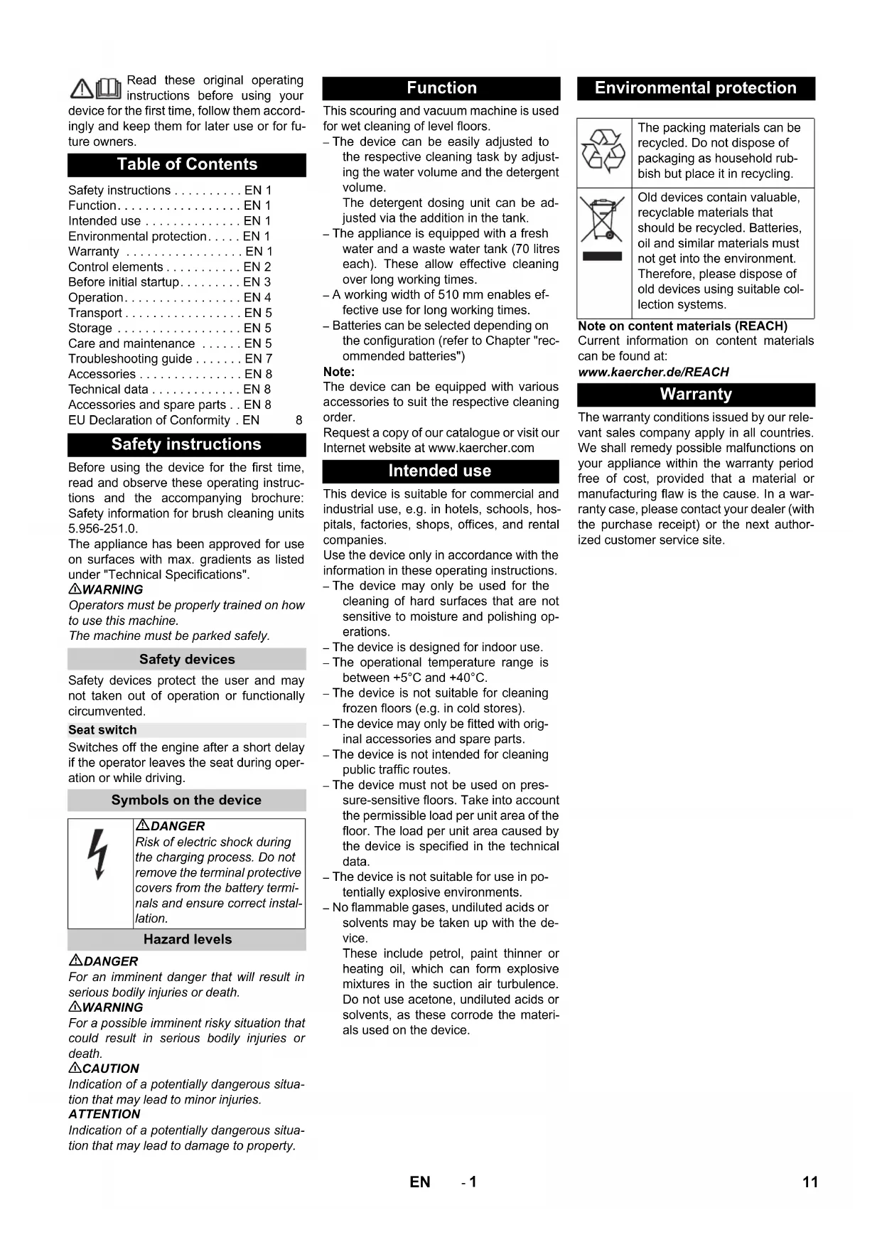
Read these original operating instructions before using your device for the first time, follow them accordingly and keep them for later use or for future owners.
Table of Contents
Safety instructions ..... EN 1
Function.....EN 1
Intended use ..... EN 1
Environmental protection.....EN 1
Warranty ...... EN 1
Control elements ..... EN 2
Before initial startup.....EN 3
Operation......EN 4
Transport....EN 5
Storage EN 5
Care and maintenance ..... EN 5
Troubleshooting guide ..... EN 7
Accessories ..... EN 8
Technical data....EN 8
Accessories and spare parts .. EN 8
EU Declaration of Conformity. EN 8
Safety instructions
Before using the device for the first time, read and observe these operating instructions and the accompanying brochure: Safety information for brush cleaning units 5.956-251.0.
The appliance has been approved for use on surfaces with max. gradients as listed under "Technical Specifications".
⚠ WARNING
Operators must be properly trained on how to use this machine.
The machine must be parked safely.
Safety devices
Safety devices protect the user and may not taken out of operation or functionally circumvented.
Seat switch
Switches off the engine after a short delay if the operator leaves the seat during operation or while driving.
Symbols on the device

DANGER
Risk of electric shock during the charging process. Do not remove the terminal protective covers from the battery terminals and ensure correct installation.
Hazard levels
DANGER
For an imminent danger that will result in serious bodily injuries or death.
⚠ WARNING
For a possible imminent risky situation that could result in serious bodily injuries or death.
△CAUTION
Indication of a potentially dangerous situation that may lead to minor injuries.
ATTENTION
Indication of a potentially dangerous situation that may lead to damage to property.
Function
This scouring and vacuum machine is used for wet cleaning of level floors.
- The device can be easily adjusted to the respective cleaning task by adjusting the water volume and the detergent volume.
The detergent dosing unit can be adjusted via the addition in the tank.
- The appliance is equipped with a fresh water and a waste water tank (70 litres each). These allow effective cleaning over long working times.
– A working width of 510 mm enables effective use for long working times.
- Batteries can be selected depending on the configuration (refer to Chapter "recommended batteries")
Note:
The device can be equipped with various accessories to suit the respective cleaning order.
Request a copy of our catalogue or visit our Internet website at www.kaercher.com
Intended use
This device is suitable for commercial and industrial use, e.g. in hotels, schools, hospitals, factories, shops, offices, and rental companies.
Use the device only in accordance with the information in these operating instructions.
- The device may only be used for the cleaning of hard surfaces that are not sensitive to moisture and polishing operations.
- The device is designed for indoor use.
- The operational temperature range is between +5^ and +40^ .
- The device is not suitable for cleaning frozen floors (e.g. in cold stores).
- The device may only be fitted with original accessories and spare parts.
– The device is not intended for cleaning public traffic routes.
- The device must not be used on pressure-sensitive floors. Take into account the permissible load per unit area of the floor. The load per unit area caused by the device is specified in the technical data.
- The device is not suitable for use in potentially explosive environments.
- No flammable gases, undiluted acids or solvents may be taken up with the device.
These include petrol, paint thinner or heating oil, which can form explosive mixtures in the suction air turbulence. Do not use acetone, undiluted acids or solvents, as these corrode the materials used on the device.
Environmental protection

The packing materials can be recycled. Do not dispose of packaging as household rubbish but place it in recycling.
Old devices contain valuable, recyclable materials that should be recycled. Batteries, oil and similar materials must not get into the environment. Therefore, please dispose of old devices using suitable collection systems.
Note on content materials (REACH)
Current information on content materials can be found at:
The warranty conditions issued by our relevant sales company apply in all countries. We shall remedy possible malfunctions on your appliance within the warranty period free of cost, provided that a material or manufacturing flaw is the cause. In a warranty case, please contact your dealer (with the purchase receipt) or the next authorized customer service site.
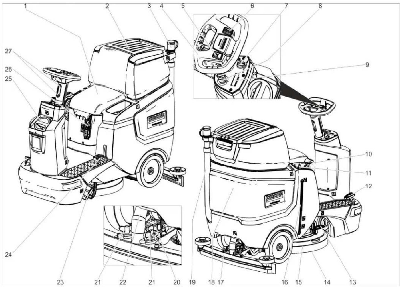
Control elements
text_image
Technical diagram of a cleaning or cleaning machine with numbered parts for identification and assembly reference.1 Seat
2 Waste water tank cap
3 Dosing equipment for dirt water
4 Steering wheel
5 Horn push button
6 Driving direction switch
7 Working speed rotary knob
8 Key-operated switch
9 Display
10 Suction bar lever
11 Water volume regulation knob
12 Accelerator pedal
13 Brush replacement pedal
14 Disc brush
15 Cleaning head
16 Fresh water filling level indicator
17 Suction bar *
18 Waste water tank
19 Waste water drain hose
20 Twist grip to incline the suction bar
21 Wing nuts for fastening the suction bar
22 Suction hose
23 Fresh water tank cap with fresh water filter
24 Raising/lowering the pedal for the cleaning head
25 Lid of fresh water tank
Filling hole for fresh water
26 Battery plug connector
27 Steering wheel height adjustment
* not in scope of delivery
Colour coding
– Control elements for the cleaning process are yellow.
– Control elements for maintenance and servicing are light gray.
Symbols on the device


Battery plug connector
Fresh water tank filling level 25%
Detergent solution dos- ing
Raising/lowering the cleaning head
Brush replacement pedal
Raising/lowering the vacuum bar
| Mop holder ** | |
| Fresh water tank drain opening | |
| Waste water tank drain opening | |
| Eyelet point |
option
Before initial startup
Batteries
 | Observe the notes on the battery, in the instructions and in the vehicle operating instructions |
 | Wear eye protection. |
 | Keep acids and batteries away from children |
 | Risk of explosion |
 | Fire, sparks, open flames and smoking are prohibited |
 | Risk of acid burns |
 | First aid |
 | Warning note |
 | Disposal |
 | Do not throw batteries in the bin |
DANGER
Risk of explosion!
Do not place tools or similar items on the battery. Short-circuit and risk of explosion. Danger of injury. Never bring wounds into contact with lead. Always clean your hands after working on batteries.
Recommended batteries
| 105 Ah - maintenance-free | |
| Order no. 6.654-141.0 | 1) |
| Volume [m3] * 2,64 | |
| Airflow [m3/h] ** 1,06 | |
| * Minimum volume of the battery charging room** Minimum air flow between battery charging room and environment | |
The device requires 2 batteries
Complete set (24 V/105 Ah) incl. connecting cable, order no. 4.039-287.0
Installing and connecting batteries
With the "Pack" variant, the batteries are already installed.
→ Disconnect the battery plug connector.
→ Pivoting the waste water tank backwards.
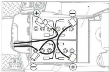
text_image
Diagram of a vehicle or road intersection with labeled points and directional indicators1 Spacer
ATTENTION
Risk of damage. Pay attention to the correct polarity.
→ Connect the battery terminals using the connecting cable provided.
→ Clamp the supplied connecting cables on the (+) and (-) battery terminals that are still free.
→ Check for correct installation of the terminal protective covers.
→ Plug in the battery connector.
ATTENTION
Risk of damage due to deep discharge. Charge the batteries before initial startup.
Charging batteries
Note:
The appliance is equipped with a total discharge protection, i.e. if the still admissible minimum of the capacity is reached, the appliance can only be driven.
Brush drive and suction are disabled.
→ Drive the device directly to the charger and do not drive on slopes.
Note:
When using other batteries (e.g. from other manufacturers), the deep discharge protection for the respective battery must be reset by Kärcher Customer Service.
△DANGER
Danger from electric shock. Note the power supply network and fuse protection - see "Charger".
Only use the charger in dry rooms with sufficient ventilation.
Note:
The average charging time is approx. 10-12 hours.
The recommended chargers (for the respective batteries) are electronically controlled and stop the charging process automatically.
DANGER
Risk of explosion. The room, where the machine is kept to charge the battery, must feature a minimum volume and an air exchange with a minimum flow rate, depending on the type of battery (see "Recommended Batteries").
Risk of explosion. The charging of wet batteries is only permitted if the waste water tank is tilted up.
→ Empty the waste water tank.
→ Set the key switch to position "0" and pull out the key.
→ Pivoting the waste water tank backwards.
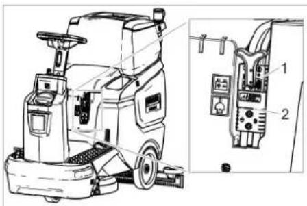
text_image
Technical diagram of a cleaning or cleaning machine with labeled parts and internal wiring connections1 Battery plug, battery side
2 Battery plug, device side
→ Detach the battery plug on the battery side.
ATTENTION
Risk of damage!
- Do not connect the charger to the device-side battery connector.
- Only use a charger that is suitable for the installed battery type:
| Battery type | Charger |
| 6.654-141.0 | 6.654-367.0 |
| 6.654-093.0 | 6.654-367.0 |
Note: Please read the operating instructions of the charger manufacturer, especially the chapters on safety instructions!
→ Connect the battery plug on the battery side with the charger.
→ Plug the mains plug of the charger into the socket.
→ Carry out the charging process in accordance with the information in the operating instructions for the charger.
Low-maintenance batteries (wet batteries)
→ One hour before the end of the charging process, add distilled water, observing the correct acid level. The battery is labelled accordingly. All cells must produce gas at the end of the charging process.
DANGER
Risk of acid burns. Refilling water when the battery is in the discharged state can lead to acid leakage!
When handling battery acid, use safety goggles and observe regulations to prevent injury and destruction of clothing. Immediately rinse off any splashed acid from the skin or clothing using copious amounts of water.
ATTENTION
Top up the batteries using only distilled or desalinated water (EN 50272-T3).
Do not use any foreign additives (so-called enhancing agents), as this will invalidate any warranty.
Maximum battery dimensions
| Length | 408 |
| Width | 348 |
| Height | 284 |
Removing the batteries
→ Turn key switch to "0".
→ Disconnect the battery plug connector.
→ Pivoting the waste water tank backwards.
→ Disconnect the cable from negative terminal of the battery.
→ Disconnect the remaining cables from the batteries.
→ Remove the batteries.
→ Dispose of the used batteries in accordance with statutory provisions.
Installing the brushes
The installation of the brushes is described in the chapter "Maintenance tasks".
Installing the suction bar
natural_image
Mechanical assembly diagram showing a valve mechanism with bolts and a pipe fitting (no text or labels)→ Insert the suction bar into the suction bar suspension in such a manner that the profiled sheet is positioned above the suspension.
→ Tighten the wing nuts.
→ Insert the suction hose.
Adjusting the steering wheel
→ Loosen both screws of the steering wheel height adjustment.
→ Set the steering wheel to the desired height.
→ Tighten both screws.
Operation
ATTENTION
Risk of damage!
Do not disconnect the battery plugs during operation.
Note:
To take all functions out of operation immediately, bring the key switch into the "0" position.
Switching the device on
→ Assume the sitting position.
→ Set the key switch to position "1".
The display shows the following one after the other:
– Period of time until the next aftersales service
- Software version, control panel
– Charging state of the battery and number of operating hours
Checking the parking brake
DANGER
Danger of accident. Before each operation, check the function of the parking brake on level ground.
→ Switch on the device.
→ Set the travel direction switch to "forward".
→ Press the accelerator pedal lightly.
→ The brake must audibly unlock. The device must roll off easily on the level. When the pedal is released, the brake engages audibly. If this is not the case, the appliance needs to be put out of operation and aftersales service needs to be called.
Driving
⚠️DANGER
Danger of accident. If the device no longer has any braking effect, proceed as follows:
If the appliance does not come to a halt on an ascent of above 2%, then the key switch must not be set to 0. The appliance must continue to be operated until a horizontal plane is achieved with it.
→ When a horizontal plane has been achieved, the appliance must be shut down and aftersales service needs to be called.
→ Additionally, observe the maintenance instructions for brakes.
DANGER
Danger of tipping over on excessively steep inclines.
→ Only drive on uphill gradients up to 8% in the direction of travel. Drive only lengthwise on uphill and downhill gradients, do not turn.
Danger of tipping when driving round bends at high speed.
Danger of slipping on wet floors.
→ Drive slowly in bends.
Risk of tipping on unstable surfaces.
→ Only move the device on stable ground. Risk of tipping over if sideways inclination is too great.
→ Only drive on uphill gradients transverse to the travel direction up to a maximum of 8%.
Driving
→ Assume the sitting position.
→ Pull the vacuum bar lever upwards and lock it in place.
→ Push the pedal for the cleaning head down and lock it in place.
→ Set the key switch to position "1".
→ Set the direction of travel using the drive direction button on the steering wheel.
→ Specify the travel speed by pressing the accelerator pedal.
→ Stopping the device: Take your foot from the accelerator pedal.
Note:
If the cleaning head is raised, the maximum speed is not affected by the working speed rotary knob.
The direction of travel can also be changed during the cleaning operation. This way, a certain position can be intensively cleaned by driving back and forth several times.
Filling with operating materials
Detergent
⚠ WARNING
Risk of damage. Only use the recommended detergents. The operator carries all increased risks relating to operational safety and increased risk of accidents if using other detergents.
Only use detergents free of solvents, salt and hydrofluoric acid.
Adhere to the safety instructions stated on the detergent packaging.
Note:
Do not use strong foaming detergents.
| Application Detergent | |
| Maintenance cleaning of all water-resistant floors | RM 746RM 780 |
| Maintenance cleaning of polished hard surfaces (e.g. granite) | RM 755 es |
| Maintenance cleaning and basic cleaning of industrial floors | RM 69 ASF |
| Maintenance cleaning and basic cleaning of fine stone tiles | RM 753 |
| Maintenance cleaning of tiles in sanitary areas | RM 751 |
| Cleaning and disinfection in sanitary areas | RM 732 |
| Coating removal on all alkaline-resistant floors (e.g. PVC) | RM 752 |
| Coating removal on linoleum floors | RM 754 |
Fresh water
→ Open the fresh water tank cap.
→ Fill the tank half full using fresh water (maximum 50 °C).
→ Fill with detergent.
→ Top up the tank with water.
→ Remove the fresh water tank cap.
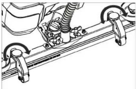
Adjusting the suction bar
Oblique position
To improve the vacuuming result on tiled floors the suction bar can be turned to an oblique position of up to 5^ .
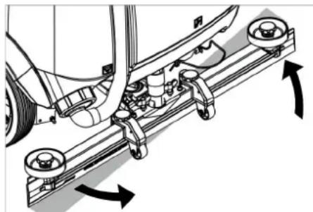
natural_image
Mechanical assembly diagram showing a vehicle's suspension system with arrows indicating motion direction (no text or labels)→ Release the wing nuts.
→ Turn the suction bar.
→ Tighten the wing nuts.
Inclination
If the vacuum result is unsatisfactory the inclination of the straight suction bar can be modified.
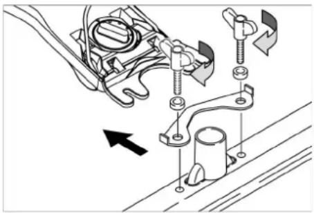
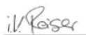
text_image
Technical diagram of a mechanical device with labeled parts 1 and 21 Twist grip
2 Clamping lever
→ Lift the tension lever.
→ Adjust the twist grip to incline the suction bar.
→ Press the tension lever downwards.
Height
The height adjustment affects the bending of the suction lips on contact with the floor.
natural_image
Technical line drawing of a mechanical assembly with rotating components (no text or symbols)→ Try adjusting the twist handles of the height adjustment until the best vacuuming result is achieved.
Adjusting the water volume
→ Adjust the water quantity using the regulating button according to the dirt on the floor covering.
Note:
Carry out initial cleaning attempts with low water volume. Increase the water volume step by step until achieving the desired cleaning result.
Cleaning mode
→ Assume the sitting position.
→ Set the key switch to position "1".
→ Set the direction of travel using the drive direction button on the steering wheel.
→ Turn the working speed rotary knob to the desired value.
The speed is shown on the display during the adjustment.
The display is shown in percentage of the maximum speed.
→ Set the water volume at the regulating valve.
→ Pull the lower half of the handle section on the vacuum bar lever upwards and hold it.
→ Press the vacuum bar lever downwards.
The vacuum bar is lowered and the suction starts.
→ Press the pedal for the cleaning head downwards/to the right, release it and allow it to move upwards.
→ Specify the travel speed by pressing the accelerator pedal.
The cleaning head is lowered, the brush drive starts and the cleaning solution will be applied.
→ Run over the surface to be cleaned.
→ Stopping the device: Take your foot from the accelerator pedal.
Finishing cleaning
→ Push the pedal for the cleaning head down until it locks into place.
→ Push the appliance a little further to vacuum up the remaining water.
→ Pull the vacuum bar lever upwards until it locks into place.
The suction turbine is switched off after a after-running time of 10 seconds.
→ Turn key switch to "0".
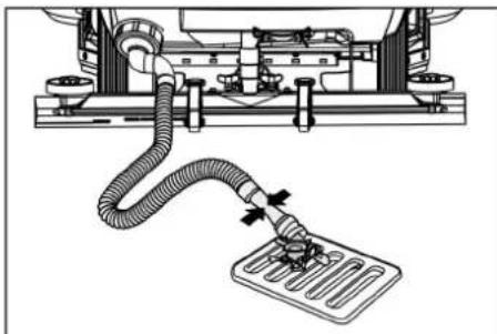
Emptying the waste water tank
Note:
When the waste water tank is full, the float switch closes the suction opening and the suction turbine runs at a higher speed.
⚠ WARNING
Please observe the local provisions regarding the wastewater treatment.
→ Take the waste water drain hose out of the support and lower it over a suitable collecting device.
Note:
The wastewater flow can be controlled by squeezing the dosing unit.
natural_image
Mechanical assembly diagram showing a pipe connection to a motor or vehicle component (no text or symbols present)→ Drain the water by opening the dosing valve on the drain hose.
→ Then rinse the wastewater container with clear water.
Empty the fresh water tank
→ Unscrew the cover on the fresh water tank.
→ Drain the fresh water.
→ Screw the cover onto the fresh water tank.
Shutting down
→ Charge battery, if required.
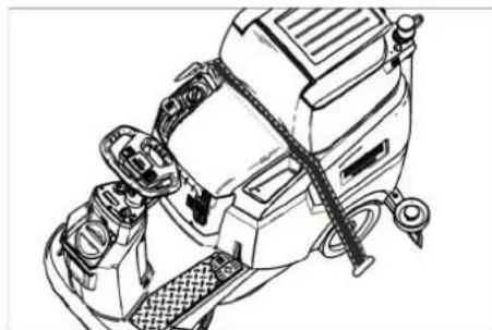
Transport
DANGER
Danger of injury! When loading or unloading the device, it may only be operated on gradients up to the maximum value (see "Technical Specifications"). Drive slowly.
CAUTION
Risk of injury and damage! Mind the weight of the device during transport.
→ Drain the fresh water tank and waste water tank prior to loading.
→ Remove the disc brush from the brush head.
natural_image
Line drawing of a mechanical device with attached hoses and a textured base (no text or symbols)→ When transporting in vehicles, secure the device against slipping and tipping over according to the applicable guidelines.
Pushing the device

text_image
Technical diagram of a vehicle engine assembly with labeled components and parts1 Unlocking lever
→ Press the unlocking lever upwards and push the appliance.
DANGER
Danger of accident due to lacking brake function.
You must press the unlocking lever down again after pushing the appliance.
Storage
△CAUTION
Risk of injury and damage! Consider the weight of the device when storing it.
→ This device may only be stored indoors.
→ Choose a storage location considering the device's maximum permissible weight to avoid affecting stability.
Care and maintenance
DANGER
Danger of injury! Before performing any work on the device, turn the key-operated switch to "0" and remove the key. Pull the battery plug.
→ Drain and dispose of the waste water and the residual fresh water.
CAUTION
Risk of injury due to overrun of the suction turbine.
The suction turbine continues to run after switch-off. Only carry out maintenance work after the suction turbine has shutdown.
Maintenance schedule
After work
ATTENTION
Risk of damage. Do not spray the device with water and do not use aggressive detergents.
→ Drain the waste water.
→ Rinse the waste water tank with clear water.
→ Clean the coarse dirt filter.
→ Clean the outside of the device with a damp cloth which has been soaked in mild washing lye.
→ Clean the vacuum lips, check for wear and replace if required.
→ Check the brushes for wear, replace if required.
→ Charging the battery: If the charging state of the battery is under 50%, charge the battery fully and without interruption. If the charging state of the battery is over 50%, only recharge the battery if the entire operation duration will be required when next used.
Weekly
→ When used regularly, charge the battery fully and without interruption at least once a week.
Monthly
→ Drain the fresh water tank and flush out deposits.
→ Clean the fresh water filter.
→ Clean the swimmer.
→ Clean the fluff filter.
→ If the device is temporarily shut down: Carry out refill charging for the battery.
→ Check battery poles for oxidation, brush off if necessary. Make sure the connection cables are firmly in place.
→ Clean the seals between the waste water tank and cover and check for tightness, replace if required.
→ Check the acid density of the cells if the batteries are not maintenance-free batteries.
→ For long periods of disuse, only park and store the device when the batteries are fully charged. Fully recharge the battery at least every month.
Annually
→ Have the prescribed inspection carried out by the customer service.
Maintenance work
Service contract
To ensure a reliable operation of the device, maintenance contracts can be concluded with the competent Kärcher sales outlet.
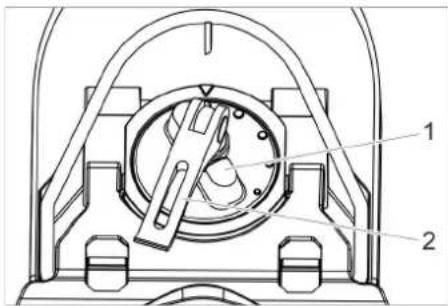
Clean the float and fluff filter
→ Open the waste water tank cap.
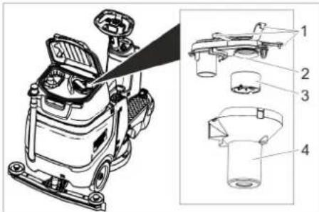
text_image
Technical diagram of a cleaning or inspection device with labeled parts including a spray gun, wash bottle, and plastic cup.1 Latching hooks
2 Fluff filter
3 Float
4 Float housing
→ Detach locking hooks.
→ Pull off the float housing in a downward direction.
→ Remove the float from the float housing and clean it.
→ Clean the fluff filter.
→ Reassemble all parts in the reverse order.
Cleaning the coarse dirt sieve
→ Open the waste water tank cap.
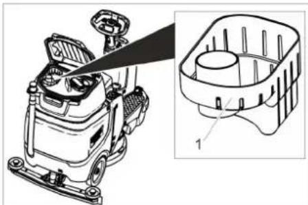
natural_image
Technical line drawing of a car dashboard with an inset showing internal components (no text or symbols)1 Coarse dirt filter
→ Pull the coarse dirt filter off in an upward direction.
→ Rinse off the coarse dirt filter under running water.
→ Reinsert the coarse dirt filter into the waste water tank.
Replacing the suction lips
→ Remove the suction bar.
→ Unscrew the star handles.
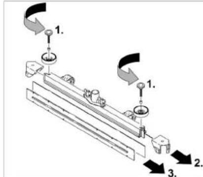
text_image
Technical diagram showing a mechanical assembly with numbered components and directional arrows indicating motion or assembly steps.→ Remove the plastic parts.
→ Remove the vacuum lips.
→ Insert the new vacuum lips.
→ Insert the plastic parts.
→ Screw in and tighten the star handles.
Replacing the disk brushes
→ Raise the cleaning head.
→ Press the pedal for changing the brushes downward beyond its resistance.
→ disc brush sideways and out from underneath the cleaning head.
→ Hold the new disc brush under the cleaning head, then press upwards and latch it into position.
Frost protection
If there is a risk of frost:
→ Empty the fresh and dirt water tanks. Park the device in a frost-protected room.
Troubleshooting guide
DANGER
Danger of injury! Before performing any work on the device, turn the key-operated switch to "0" and remove the key. Pull the battery plug.
→ Drain and dispose of the waste water and the residual fresh water.
△CAUTION
Risk of injury due to overrun of the suction turbine.
The suction turbine continues to run after switch-off. Only carry out maintenance work after the suction turbine has shut-down.
| Malfunction Rectification | |
| Device does not start Seat switch | ch not operated, sit down on the seat.The machine only operates if the operator is seated on the seat. |
| Plug in the battery connector. | |
| Set the key switch to position "1". | |
| Take your foot off the accelerator before switching on the key switch. If the fault still recurs, call customer service. | |
| Check the battery and charge if necessary. | |
| Device does not move | Press the unlocking lever downwards (see "Transport/Pushing the appliance"). |
| Low water quantity Increase the | water volume at the water volume regulating knob. |
| Check fresh water level, top up tank if necessary. | |
| Clean the fresh water filter. | |
| Check the hoses for clogging; clean if necessary. | |
| Poor suction performance | Waste water tank is full; shut off the device and empty the waste water tank |
| Clean the seals between the waste water tank and cover and check for tightness, replace if required | |
| Check the fluff filter for soiling, clean if necessary. | |
| Clean the vacuum lips on the suction bar, turn or replace if required. | |
| Check the suction bar for clogging and remove any clogging if necessary | |
| Check that the cap on the waste water drain hose is closed | |
| Check the suction hose for clogging; clean if necessary. | |
| Check the suction hose for leaks; clean if necessary. | |
| Check dirt water drain hose to see it is leak-proof. | |
| Check the setting of the suction bar. | |
| Attach additional weight (accessory) to the vacuum bar. | |
| Unsatisfactory cleaning result | Check the brushes for wear, replace if required. |
| Check the suitability of the brush type and detergent used. | |
| Speed of suction turbine has increased | Empty the waste water tank. |
| Clean the swimmer. | |
| Clean/check the fluff filter. | |
| Check the suction hose for clogging; clean if necessary. | |
| Check the suction bar for clogging and remove any clogging if necessary | |
| Brush does not rotate Check if the brushes are blocked by foreign bodies and remove the foreign bodies if necessary. | |
| Contact Customer Service in the case of malfunctions that cannot be corrected using this table. | |
Accessories
| Description Part no. Description | ||
| Disc brush, red (medium, standard) 4.905-026.0 For the use with all common cleaning tasks. | ||
| Disc brush, natural colour (soft) | 4.905-027.0 | Made of natural fibres for spot cleaning and polishing. |
| Disc brush, black (hard) 4.905-029.0 For heavy soiling and for deep cleaning. For robust floorings only. | ||
| Pad drive board 4.762-534.0 For cleaning with pads. With quick change coupling and center lock. | ||
| Pad, red (medium soft) 6.369-079.0 For cleaning all floors. | ||
| Pad, green (medium hard) 6.369-078.0 For cleaning heavily soiled floors and for basic cleaning. | ||
| Pad, black (hard) 6.369-077.0 For stubborn soiling and for basic cleaning. | ||
| Pad, beige (light grain) | 6.369-468.0 | For polishing and refreshing of hard and flexible floorings. |
| Pad, beige (natural hair proportion) | 6.371-146.0 | |
| Suction bar, 850 mm, straight | 4.777-401.0 | |
| Suction bar, 850 mm, bent | 4.777-411.0 | |
| Set homebase box | 4.035-406.0 | |
| Flashing beacon | 4.039-267.0 | |
| Fleet Management module | 4.039-268.0 | |
| Bag holder | 4.039-269.0 | |
| Presweep unit | 4.039-270.0 | |
| Mop holder | 4.039-271.0 | |
| Spray mop | 5.999-045.0 | |
| Pliers for course dirt | 6.999-113.0 | |
Technical data
| Power | ||
| Nominal voltage | V | 24 |
| Battery capacity | Ah (5h) | 76 / 105 |
| Mean power input | W | 1400 |
| Nominal power engine | W | 300 |
| Suction motor power | W | 600 |
| Brush engine output | W | 500 |
| Protection class | IPX 3 | |
| Suctioning | ||
| Suction performance, air quantity | l/s | 17 |
| Cleaning power, negative pressure, max. | kPa | 120 |
| Cleaning brushes | ||
| Working width | mm | 510 |
| Brush diameter | mm | 510 |
| Brush speed, loaded | rpm | 155 |
| Brush speed, unloaded | rpm | 180 |
| Dimensions and weights | ||
| Driving speed, max. | km/h | 6 |
| Slope max. | % | 8 |
| Theoretical surface coverage | m^2/h | 2300 |
| Fresh water tank volume | l | 70 |
| Waste water tank volume | l | 75 |
| Max. water temperature | °C | 50 |
| Ambient temperature | °C | 5...40 |
| Length | mm | 1310 |
| Width (without suction bar) | mm | 590 |
| Height | mm | 1066 |
| Approved total weight | kg | 340 |
| Transport weight (tanks empty, without driver) | kg | 194 |
Load per unit area (with driver and full fresh water tank)
| Front wheel | N/cm2 | 102 |
| Rear wheel | N/cm2 | 124 |
| Determined values in acc. with EN 60335-2-72 | ||
| Vibration total value on arms | m/s2 | <2,5 |
| K uncertainty | m/s2 | 0,2 |
| Vibration total value on seat area | m/s2 | <0,5 |
| K uncertainty | m/s2 | 0,1 |
| Sound level L_pA | dB(A) | 66 |
| Uncertainty K_pA | dB(A) | 2 |
| Sound power level L_WA + Uncertainty K_WA | dB(A) | 80,3 |
Accessories and spare parts
Only use original accessories and original spare parts. They ensure that the appliance will run both reliably and smoothly. Information on accessories and spare parts can be found at www.kaercher.com.
EU Declaration of Conformity
We hereby declare that the machine described below complies with the relevant basic safety and health requirements in the EU Directives, both in its basic design and construction as well as in the version placed in circulation by us. This declaration is invalidated by any changes made to the machine that are not approved by us.
Product: Floor cleaning ride-on machine
Type: 1,161-xxx
Currently applicable EU Directives
2006/42/EC (+2009/127/EC)
2014/30/EU
2000/14/EC
2014/53/EU (TCU)
Harmonized standards used
EN 60335-1
EN 60335-2-72
EN 62233: 2008
EN 55012: 2007 + A1: 2009
EN 61000-6-2: 2005
TCU
EN 301 511 V12.5.1
EN 300 440 V2.1.1
EN 300 328 V2.2.2
EN 300 330 V2.1.
National standards used
The signatories act on behalf of and with the authority of the company management.
Chairman of the Board of Management

S. Reiser
Director Regulatory Affairs & Certification
Documentation supervisor:
S. Reiser
Alfred Kärcher SE & Co. KG
71364 Winnenden (Germany)
Tel.: +49 7195 14-0
Fax: +49 7195 14-2212
Winnenden, 2021/11/01
text_image
Technical diagram of a cleaning or cleaning machine with numbered parts for identification and assembly reference.text_image
Diagram of a vehicle interior with labeled components and directional arrows indicating movement or flow1 Entretoise
MISE EN GARDE
text_image
Technical diagram of a cleaning or cleaning machine with labeled parts and an inset close-up view showing internal components.natural_image
Mechanical assembly diagram showing components like bolts, springs, and a pipe fitting (no text or labels)natural_image
Mechanical assembly diagram showing a vehicle with wheels, suspension components, and directional arrows indicating motion (no text or labels)text_image
Technical diagram of a mechanical device with labeled parts 1 and 2natural_image
Technical line drawing of a mechanical assembly with springs and levers (no text or symbols)natural_image
Technical diagram of a mechanical assembly with hoses and components, no visible text or symbolsnatural_image
Line drawing of a mechanical device with attached components (no text or symbols)text_image
Technical diagram of a vehicle engine assembly with labeled components and partstext_image
Technical diagram of a cleaning machine with labeled parts including handle, spray bottle, and plastic cupnatural_image
Technical line drawing of a car dashboard and steering wheel assembly (no text or symbols)2006/42/CE (+2009/127/CE)
2014/30/UE
2000/14/CE
2014/53/UE (TCU)
H. Jenner
Chairman of the Board of Management
S. Reiser
Director Regulatory Affairs & Certification
71364 Winnenden (Germany)
Winnenden, 01/11/2021
text_image
Technical diagram of a cleaning or cleaning machine with numbered parts for identification and assembly reference.text_image
Diagram of a vehicle interior with labeled components and directional arrows, including plus/minus signs and numbered point 1.1 Distanziale
ATTENZIONE
text_image
Technical diagram of a cleaning or cleaning machine with labeled parts and internal wiring connectionsnatural_image
Mechanical assembly diagram showing components like bolts, brackets, and a valve (no text or labels)natural_image
Mechanical assembly diagram showing a vehicle with wheels and directional arrows indicating motion (no text or symbols)text_image
Technical diagram of a mechanical device with labeled parts 1 and 2natural_image
Technical line drawing of a mechanical assembly with rotating components (no text or symbols)natural_image
Technical diagram showing a mechanical assembly with hoses and a motor base (no text or symbols)natural_image
Line drawing of a helmet with attached sensors and gear (no text or symbols)text_image
Technical diagram of a mechanical assembly with labeled components and cross-sectional view1 Leva di sblocco
text_image
Technical diagram of a cleaning machine with labeled parts including handle, spray bottle, and plastic cup1 Ganci di arresto
2 Filtro pelucchi
3 Galleggiante
natural_image
Technical line drawing of a car dashboard with an inset showing internal components (no text or symbols)2006/42/CE (+2009/127/CE)
2014/30/UE
2000/14/CE
2014/53/UE (TCU)
71364 Winnenden (Germania)
Tel.: +49 7195 14-0
Fax: +49 7195 14-2212
Winnenden, 2021/11/01
text_image
Technical diagram of a cleaning or cleaning machine with numbered parts for identification and assembly reference.1 Stoel
2 Deksel vuilwaterreservoir
25 Deksel schoonwaterreservoir Vulopening schoon water
26 Accustekker
text_image
Diagram of a vehicle or road intersection with labeled points and directional indicators1 Afstandsstuk
OPGELET
text_image
Technical diagram of an industrial cleaning machine with labeled components and exploded viewnatural_image
Mechanical assembly diagram showing components like bolts, brackets, and a pipe connection (no text or labels)natural_image
Mechanical assembly diagram showing a vehicle with rotating components and directional arrows indicating motion (no text or labels)text_image
Technical diagram of a mechanical device with labeled parts 1 and 21 Draaigreep
2 Spanhefboom
natural_image
Technical line drawing of a mechanical assembly with springs and rotating components (no text or symbols)natural_image
Technical diagram showing a mechanical assembly with hoses and a slide, no visible text or symbolsnatural_image
Line drawing of a mechanical device with attached hoses and brackets (no text or symbols)text_image
Technical diagram of a mechanical assembly with labeled components and cross-sectional views1 Ontgrendelingshendel
text_image
Technical diagram of a cleaning machine with labeled parts including spray gun, wash bottle, and plastic cup.1 Grendelhaak
2 Pluizenzeef
3 Vlotter
4 Vlotterbehuizing
natural_image
Technical line drawing of a mechanical device with an inset showing a close-up view of a cylindrical component (no text or symbols present)1 Grofvuilzeef
Director Regulatory Affairs & Certification
Winnenden, 2021/11/01
text_image
Technical diagram of a cleaning or cleaning machine with numbered parts for identification and assembly reference.text_image
Diagram of a vehicle interior with labeled components and wiring connections, including plus/minus signs and numbered indicators.1 Distanciador
ATENCIÓN
text_image
Technical diagram of a cleaning or cleaning machine with labeled parts and an inset view showing internal components.natural_image
Mechanical assembly diagram showing components like bolts, springs, and a cylinder on a wooden surface (no text or labels)natural_image
Mechanical assembly diagram showing a vehicle's wheel assembly with directional arrows indicating motion (no text or labels)text_image
Technical diagram of a mechanical device with labeled components 1 and 2natural_image
Technical line drawing of a mechanical assembly with rotating components (no text or symbols)natural_image
Mechanical assembly diagram showing a pipe connection to a motor or fan (no text or symbols present)natural_image
Line drawing of a helmet with attached sensors and gear (no text or symbols)text_image
Technical diagram of a mechanical assembly with labeled components and cross-sectional viewtext_image
Technical diagram of a cleaning machine with labeled parts including handle, spray bottle, and plastic cupnatural_image
Technical illustration of a car dashboard with an inset showing internal components (no text or symbols)2006/42/CE (+2009/127/CE)
2014/30/UE
2000/14/CE
2014/53/UE (TCU)
Chairman of the Board of Management

S. Reiser
Director Regulatory Affairs & Certification
Winnenden, 01/11/2021
text_image
Technical diagram of a cleaning or cleaning machine with numbered parts for identification and assembly reference.text_image
Diagram of a vehicle or road intersection with labeled points and directional indicators1 Espaçador
ATENÇÃO
text_image
Technical diagram of a cleaning or cleaning machine with labeled parts and an inset view showing internal components.1 Ficha da bateria, lado da bateria
2 Ficha da bateria, lado do aparelho
Desmontar as baterias
natural_image
Mechanical assembly diagram showing components like bolts, brackets, and a pipe fitting (no text or labels)natural_image
Mechanical assembly diagram showing a vehicle's suspension system with arrows indicating motion direction (no text or labels)text_image
Technical diagram of a mechanical device with labeled parts 1 and 2natural_image
Technical line drawing of a mechanical assembly with spring and mounting brackets (no text or symbols)natural_image
Technical diagram showing a mechanical assembly with hoses and a motor base (no text or symbols)natural_image
Line drawing of a helmet with attached hoses and sensor components (no text or symbols)text_image
Technical diagram of a mechanical assembly with labeled components, showing internal components and parts of a vehicle or machine.text_image
Technical diagram of a cleaning machine with labeled parts including handle, valve, and socket1 Gancho de engate
2 Filtro de cotão
3 Flutuador
natural_image
Technical line drawing of a car dashboard and internal components, showing part assembly (no text or symbols)Winnenden, 01/11/2021
text_image
Technical diagram of a cleaning or cleaning machine with numbered parts for identification and assembly reference.text_image
Diagram of a vehicle electrical panel layout with labeled terminals and wiring connections1 Afstandsstykke
BEMAERK
Risiko for beskadigelse. Sørg for korrekt polaritet.
text_image
Technical diagram of a cleaning or cleaning machine with labeled parts and an inset view showing internal components.1 Batteristik, batteriside
2 Batteristik, maskinside
natural_image
Mechanical assembly diagram showing components like bolts, brackets, and a pipe fitting (no text or labels)natural_image
Mechanical assembly diagram showing a vehicle's wheel and suspension components with directional arrows (no text or labels)text_image
Technical diagram of a mechanical device with labeled parts 1 and 21 Drejehändtag
2 Spændehåndtag
natural_image
Technical line drawing of a mechanical assembly with springs and rotating components (no text or symbols)natural_image
Mechanical assembly diagram showing a pipe connection to a motor or vehicle component (no text or symbols present)natural_image
Line drawing of a mechanical device with attached hoses and brackets (no text or symbols)text_image
Technical diagram of a vehicle engine assembly with labeled components and parts1 Åbningshändtag
text_image
Technical diagram of a cleaning machine with labeled parts including handle, valve, and component 4natural_image
Technical line drawing of a car dashboard with an inset showing internal components (no text or symbols)1 Grovsi
→ Træk grov snavs filteret ud opad.
→ Skyl grov snavs filteret under flydende vand.
→ Sæt grov snavs filteret ind i snavse-vandsbeholderen igen.
2006/42/EF (+2009/127/EF)
2014/30/EU
2000/14/EF
2014/53/EU (TCU)

Chairman of the Board of Management

S. Reiser
Director Regulatory Affairs & Certification
Winnenden, 2021/11/01
text_image
Technical diagram of a cleaning or cleaning machine with numbered parts for identification and assembly reference.1 F e s t e
2 Deksel spillvannstank
text_image
Diagram of a vehicle electrical panel layout with labeled terminals and wiring connections1 Avstandsstykke
OBS
text_image
Technical diagram of a cleaning or cleaning machine with labeled parts and exploded viewnatural_image
Mechanical assembly diagram showing components like bolts, brackets, and a pipe fitting (no text or labels)natural_image
Mechanical assembly diagram showing a vehicle's wheel and suspension components with directional arrows (no text or labels)→ Løsne vingemutrene.
→ Drei sugebommen.
→ Stram vingemutrene.
Helling
Ved utilstrekkelig sugeresultat kan skråstillingen for den rette sugebommen endres.

text_image
Technical diagram of a mechanical device with labeled parts 1 and 21 Vrihåndtak
2 Spennhendel
→ Løft strammespaken.
→ Juster dreiehåndtaket for justering av vinkelen for sugebommen.
→ Trykk ned strammehendelen.
Høyde
natural_image
Technical line drawing of a mechanical assembly with rotating components (no text or symbols)Still inn vannmengden
natural_image
Technical diagram showing a mechanical assembly with hoses and a foot pusher (no text or symbols)natural_image
Line drawing of a helmet with attached sensors and gear (no text or symbols)text_image
Technical diagram of a vehicle engine assembly with labeled parts and structural details1 Frigjøringsspak
text_image
Technical diagram of a cleaning machine with labeled parts including spray gun, handle, and component 41 Festekrok
2 L o f i l t e r
3 F l o t t ø r
4 Flottørhus
natural_image
Technical line drawing of a cleaning machine with an inset showing its internal components (no text or symbols present)1 Grovsmussil
2006/42/EF (+2009/127/EF)
2014/30/EU
2000/14/EF
2014/53/EU (TCU)
Anvendte harmoniserte standarder
NEK EN 60335-1
EN 60335-2-72
EN 62233: 2008
EN 55012: 2007 + A1: 2009
EN 61000-6-2: 2005
TCU
EN 301 511 V12.5.1
EN 300 440 V2.1.1
EN 300 328 V2.2.2
EN 300 330 V2.1.1

Chairman of the Board of Management

Director Regulatory Affairs & Certification
text_image
Technical diagram of a cleaning or cleaning machine with numbered parts for identification and assembly reference.1 S ä t e
text_image
Diagram of a vehicle electrical panel layout with labeled terminals and wiring connections1 Distanselement
AKTA
text_image
Technical diagram of a cleaning or cleaning machine with labeled parts and exploded viewnatural_image
Mechanical assembly diagram showing components like bolts, brackets, and a pipe fitting (no text or labels)natural_image
Mechanical assembly diagram showing a vehicle's wheel and suspension components with directional arrows (no text or labels)→ Lossa vingmuttrar.
→ Vrid sugskenan.
→ Dra fast vingmuttrarna.
Lutning
text_image
Technical diagram of a mechanical device with labeled parts 1 and 21 Vridhandtag
2 Spännarm
natural_image
Technical line drawing of a mechanical assembly with rotating components (no text or symbols)natural_image
Technical diagram of a mechanical assembly with hoses and components, no visible text or symbolsnatural_image
Line drawing of a mechanical device with hoses and control knobs (no text or symbols)text_image
Technical diagram of a vehicle engine showing internal components and labeled parts1 Frigöringsspak
text_image
Technical diagram of a cleaning machine with labeled parts and exploded view1 Spärrhake
2 Luddfilter
3 Flottör
4 Flottörkapsling
natural_image
Technical line drawing of a cleaning machine with an inset showing internal components (no text or symbols)1 Grovsmutssil
Chairman of the Board of Management

S. Reiser
Director Regulatory Affairs & Certification
Winnenden, 2021/11/01
text_image
Technical diagram of a cleaning or cleaning machine with numbered parts for identification and assembly reference.text_image
Diagram of a vehicle electrical panel layout with labeled terminals and wiring connections1 Välikappale
HUOMAUTUS
text_image
Technical diagram of a cleaning or cleaning machine with labeled parts and exploded viewnatural_image
Mechanical assembly diagram showing components like bolts, brackets, and a pipe fitting (no text or labels)natural_image
Mechanical assembly diagram showing a vehicle's wheel and suspension components with directional arrows (no text or labels)text_image
Technical diagram of a mechanical device with labeled parts 1 and 21 Kääntökahva
2 Kiristyskahva
natural_image
Technical line drawing of a mechanical assembly with springs and rotating components (no text or symbols)natural_image
Technical diagram showing a mechanical assembly with hoses and a motor base (no text or symbols)natural_image
Line drawing of a mechanical device with attached hoses and brackets (no text or symbols)text_image
Technical diagram of a mechanical assembly with labeled components, showing internal components and parts of a vehicle or machine.text_image
Technical diagram of a cleaning machine with labeled parts including spray gun, handle, and component 41 Lukitushaat
2 Nukkasihti
3 Uimuri
4 Uimurikotelo
natural_image
Technical line drawing of a cleaning machine with an inset showing its internal components (no text or symbols present)1 Karkean lian seula
text_image
Technical diagram showing a mechanical assembly with numbered components and directional arrows indicating motion or assembly steps.Winnenden, 1.11.2021
text_image
Technical diagram of a cleaning or cleaning machine with numbered parts for identification and assembly reference.text_image
Diagram of a vehicle or road intersection with labeled points and directional arrows indicating movement or flow.1 Οδηγός απόστασης
ΠΡΟΣΟΧΗ
text_image
Technical diagram of a cleaning or cleaning machine with labeled parts and an inset view showing internal components.natural_image
Mechanical assembly diagram showing components like bolts, springs, and a cylinder on a wooden surface (no text or labels)natural_image
Mechanical assembly diagram showing a vehicle with rotating components and directional arrows indicating motion (no text or symbols)text_image
Technical diagram of a mechanical device with labeled parts 1 and 2natural_image
Technical line drawing of a mechanical assembly with rotating components (no text or symbols)natural_image
Technical diagram of a mechanical assembly with hoses and components, no visible text or symbolsnatural_image
Line drawing of a mechanical device with attached components (no text or symbols)text_image
Technical diagram of a vehicle engine compartment with labeled parts and structural detailstext_image
Technical diagram of a cleaning machine with labeled parts including handle, spray bottle, and cupnatural_image
Technical line drawing of a car dashboard and internal components, showing front view and side view (no text or symbols)H. Jenner Chairman of the Board of Management

S. Reiser Director Regulatory Affairs & Certification
Winnenden, 2021/11/01
text_image
Technical diagram of a cleaning or cleaning machine with numbered parts for identification and assembly reference.1 K o l t u k
text_image
Diagram of a vehicle electrical panel layout with labeled terminals and wiring connections1 Ara parça
DİKKAT
text_image
Technical diagram of a cleaning or cleaning machine with labeled parts and exploded viewnatural_image
Mechanical assembly diagram showing components like bolts, clamps, and a valve (no text or labels)natural_image
Mechanical assembly diagram showing a vehicle's internal components and directional arrows (no text or labels)text_image
Technical diagram of a mechanical device with labeled parts 1 and 21 D ü ğme
2 Mandal
natural_image
Technical line drawing of a mechanical assembly with rotating components (no text or symbols)natural_image
Technical diagram showing a mechanical assembly with hoses and a foot pusher (no text or symbols)text_image
Technical diagram of a vehicle's internal components with numbered labels pointing to parts of the engine and chassis.1 Kilit açma kolu
text_image
Technical diagram of a cleaning machine with labeled parts including handle, jaw, and component 4natural_image
Technical line drawing of a car interior with a zoomed-in view showing internal components (no text or symbols)1 Kaba kir süzgeci
text_image
Technical diagram showing a mechanical assembly with numbered components and directional arrows indicating motion or assembly steps.
Chairman of the Board of Management
S. Reiser
Director Regulatory Affairs & Certification
Winnenden, 2021/11/01
text_image
Technical diagram of a cleaning or cleaning machine with numbered parts for identification and assembly reference.text_image
Diagram of a vehicle interior with labeled components and directional arrows, including plus/minus signs and numbered point 1.1 Распорки
ВНИМАНИЕ
text_image
Technical diagram of a cleaning or cleaning machine with labeled parts and exploded viewnatural_image
Mechanical assembly diagram showing components like bolts, hoses, and a pipe fitting (no text or labels)natural_image
Mechanical assembly diagram showing motor components and directional arrows (no text or labels)text_image
Technical diagram of a mechanical device with labeled parts 1 and 21 Вращающаяся ручка
2 Натяжной рычаг
natural_image
Technical line drawing of a mechanical assembly with rotating components (no text or symbols)natural_image
Technical diagram of a mechanical assembly with hoses and components, no visible text or symbolsnatural_image
Line drawing of a mechanical device with attached components (no text or symbols)text_image
Technical diagram of a mechanical assembly with labeled parts, showing internal components and structural details.text_image
Technical diagram of a cleaning machine with labeled parts and exploded viewnatural_image
Technical line drawing of a cleaning or inspection device with an inset showing internal components (no text or symbols)text_image
Technical diagram showing a mechanical assembly with numbered components and directional arrows indicating motion or assembly steps.
H. Jenner
Chairman of the Board of Management

S. Reiser
Director Regulatory Affairs & Certification
text_image
Technical diagram of a cleaning or cleaning machine with numbered parts for identification and assembly reference.text_image
Diagram of a vehicle or road intersection with labeled points and directional indicators1 T á v t a r t ó
FIGYELEM
text_image
Technical diagram of a cleaning or cleaning machine with labeled parts and internal wiring connectionsnatural_image
Mechanical assembly diagram showing a lever mechanism with bolts and a cylindrical component, no text or symbols presentnatural_image
Mechanical assembly diagram showing a vehicle's wheel and suspension components with directional arrows (no text or labels)text_image
Technical diagram of a mechanical device with labeled parts 1 and 21 Forgó fogantyú
2 Feszítőkar
natural_image
Technical line drawing of a mechanical assembly with springs and rotating components (no text or symbols)natural_image
Technical diagram showing a mechanical assembly with hoses and a foot pusher (no text or symbols)natural_image
Line drawing of a mechanical device with attached components (no text or symbols)text_image
Technical diagram of a vehicle engine assembly with labeled components and parts1 Kireteszelő kar
text_image
Technical diagram of a cleaning machine with labeled parts including handle, jaw, and component 41 Reteszelő kapocs
2 Bolyhszürő
3 Úszó
4 Úszóház
natural_image
Technical line drawing of a mechanical device with an inset showing a close-up of its internal components (no text or symbols present)Chairman of the Board of Management
S. Reiser
Director Regulatory Affairs & Certification
Winnenden, 2021/11/01
text_image
Technical diagram of a cleaning or cleaning machine with numbered parts for identification and assembly reference.1 Sedadlo
text_image
Diagram of a vehicle or road intersection with labeled points and directional indicators1 R o z p ěrka
POZOR
text_image
Technical diagram of a cleaning or cleaning machine with labeled parts and internal wiring connections1 Konektor baterie, strana baterie
natural_image
Mechanical assembly diagram showing components like bolts, brackets, and a pipe fitting (no text or labels)natural_image
Mechanical assembly diagram showing motor components and directional arrows (no text or labels)text_image
Technical diagram of a mechanical device with labeled parts 1 and 21 O t o čné držadlo
2 Upínací páčka
natural_image
Technical line drawing of a mechanical assembly with rotating components (no text or symbols)natural_image
Mechanical assembly diagram showing a pipe connection to a motor or fan (no text or symbols present)natural_image
Line drawing of a mechanical device with attached components (no text or symbols)text_image
Technical diagram of a vehicle engine assembly with labeled components and parts1 Odjišťovací páčka
text_image
Technical diagram of a cleaning machine with labeled parts including handle, valve, and socket1 A r e t a ční hák
2 Sítko na vlákna
3 Plovák
4 Pouzdro plováku
natural_image
Technical line drawing of a car dashboard with an inset showing internal components (no text or symbols)1 Síto na hrubé nečistoty
2006/42/ES (+2009/127/ES)
2014/30/EU
2000/14/ES
2014/53/EU (TCU)
Winnenden, 2021/11/01
text_image
Technical diagram of a cleaning or cleaning machine with numbered parts for identification and assembly reference.text_image
Diagram of a vehicle interior with labeled components and directional arrows indicating movement or flow1 Distančnik
POZOR
text_image
Technical diagram of a cleaning or inspection machine with labeled parts and internal wiring connections1 V t i č baterije, na strani baterije
2 V t i č baterije, na strani naprave
→ Izvlecite vtič pri akumulatorski bateriji.
POZOR
natural_image
Mechanical assembly diagram showing components like bolts, brackets, and a pipe fitting (no text or labels)→ Sesalni nosilec vstavite v njegovo obešenje tako, da oblikovna pločevina leži nad obešenjem.
→ Pritegnite krilate matice.
→ Nataknite gibko sesalno cev.
Prilagajanje volana
→ Sprostite oba vijaka za nastavljanje višine krmila.
→ Krmilo nastavite na želeno višino.
→ Pritegnite oba vijaka.
Obratovanje
POZOR
natural_image
Mechanical assembly diagram showing a vehicle's wheel and suspension components with directional arrows (no text or labels)→ Sprostite krilate matice.
→ Obrnite sesalni prečnik.
→ Pritegnite krilate matice.
Nagib
text_image
Technical diagram of a mechanical device with labeled parts 1 and 21 Vrtljiv ročaj
2 Vpenjalni vzvod
→ Dvignite napenjalno ročico.
→ Nastavite vrtljivi ročaj za nagib sesalne-ga prečnika.
→ Napenjalno ročico pritisnite navzdol.
Višina
natural_image
Technical line drawing of a mechanical assembly with springs and levers (no text or symbols)natural_image
Technical diagram showing a mechanical assembly with hoses and a component, no visible text or symbols→ Vodo izpustite iz izpustne cevi tako, da odprete dozirno napravo.
→ Potem posodo za umazano vodo splak-nite s čisto vodo.
natural_image
Technical line drawing of a mechanical device with hoses and brackets (no text or symbols)text_image
Technical diagram of a vehicle engine assembly with labeled components and partstext_image
Technical diagram of a cleaning machine with labeled parts including handle, jaw, and gear assembly1 Zaskočni kavelj
2 Sito za kosme
3 Plovec
4 Ohišje plovca
→ Sprostite zaskočni kavelj.
→ Ohišje plovca snemite v smeri navzdol.
→ Plovec odstranite iz ohišja in ga očistite.
→ Očistite sito za kosme.
→ Vse dele ponovno sestavite v obratnem vrstnem redu.
natural_image
Technical line drawing of a car dashboard with an inset showing internal components (no text or symbols)text_image
Technical diagram showing a mechanical assembly with numbered components and directional arrows indicating motion or assembly steps.→ Odstranite plastične dele.
→ Odstranite sesalne nastavke.
→ Vrinite nove sesalne brisalce.
→ Namestite plastične dele.
→ Privijte zvezdasta ročaja in ju zategnite.
Zamenjava kolutne krtače
→ Dvignite čistilno glavo.
→ Pedal za menjavo krtače potisnite navzdol preko upora.
→ Kolutno krtačo izvlecite ob strani pod či-stilno glavo.
→ Novo kolutno krtačo držite pod čistilno glavo in jo potisnite navzgor, da se za- skoči.
2006/42/ES (+2009/127/ES)
2014/30/EU
2000/14/ES
2014/53/EU (TCU)
Chairman of the Board of Management

S. Reiser
Director Regulatory Affairs & Certification
71364 Winnenden (Germany)
Tel.: +49 7195 14-0
Fax: +49 7195 14-2212
Winnenden, 2021/11/01
text_image
Technical diagram of a cleaning or cleaning machine with numbered parts for identification and assembly reference.1 Fotel operatora
text_image
Diagram of a vehicle electrical panel layout with labeled terminals and wiring connectionstext_image
Technical diagram of a cleaning or cleaning machine with labeled parts and an inset view showing internal components.Zalecane akumulatory
natural_image
Mechanical assembly diagram showing components like bolts, springs, and a cylinder on a wooden surface (no text or labels)natural_image
Mechanical assembly diagram showing motor components and directional arrows (no text or labels)text_image
Technical diagram of a mechanical device with labeled parts 1 and 2natural_image
Technical line drawing of a mechanical assembly with springs and rotating components (no text or symbols)natural_image
Technical diagram of a mechanical assembly with hoses and components, no visible text or symbolsnatural_image
Line drawing of a mechanical device with attached components (no text or symbols)text_image
Technical diagram of a vehicle engine compartment with labeled parts and component annotationstext_image
Technical diagram of a cleaning machine with labeled parts including handle, valve, and socketnatural_image
Technical line drawing of a mechanical device with an inset showing a component detail (no text or symbols present)2006/42/WE (+2009/127/WE)
2014/30/UE
2000/14/WE
2014/53/EU (TCU)

Chairman of the Board of Management
Director Regulatory Affairs & Certification
text_image
Technical diagram of a cleaning or cleaning machine with numbered parts for identification and assembly reference.text_image
Diagram of a vehicle or road intersection with labeled points and directional indicators1 Distanțier
ATENTIE
natural_image
Technical line drawing of a cleaning or cleaning machine with labeled parts (no text or symbols present)natural_image
Mechanical assembly diagram showing components like bolts, brackets, and a pipe connection (no text or labels)natural_image
Mechanical assembly diagram showing a vehicle's wheel and suspension system with directional arrows (no text or labels)→ Eliberati piulitele fluture.
→ Rotiti bara de aspiratie.
→ Strângeti piulițele fluture.
Înclinarea
text_image
Technical diagram of a mechanical device with labeled parts 1 and 21 Mâner rotativ
natural_image
Technical line drawing of a mechanical assembly with springs and rotating components (no text or symbols)natural_image
Technical diagram of a mechanical assembly with hoses and components, no visible text or symbolsnatural_image
Line drawing of a mechanical device with attached components (no text or symbols)text_image
Technical diagram of a vehicle engine assembly with labeled components and parts1 Maneta de deblocare
text_image
Technical diagram of a cleaning machine with labeled parts including handle, valve, and internal componentsnatural_image
Technical line drawing of a car dashboard with an inset showing internal components (no text or symbols)Directive UE relevante
2006/42/CE (+2009/127/CE)
2014/30/UE
2000/14/UE
2014/53/UE (TCU)
Norme de aplicare armonizate
EN 60335-1
EN 60335-2-72
EN 62233: 2008
EN 55012: 2007 + A1: 2009
EN 61000-6-2: 2005
TCU
EN 301 511 V12.5.1
EN 300 440 V2.1.1
EN 300 328 V2.2.2
EN 300 330 V2.1.1

Chairman of the Board of Management
S. Reiser
Director Regulatory Affairs & Certification
71364 Winnenden (Germany - Germania)
Tel.: +49 7195 14-0
Fax: +49 7195 14-2212
Winnenden, 2021/11/01
text_image
Technical diagram of a cleaning or cleaning machine with numbered parts for identification and assembly reference.text_image
Diagram of a vehicle electrical panel layout with labeled components and wiring paths1 Rozpierka
POZOR
Nebezpečenstvo poškodenia. Dbajte na správnu polaritu.
text_image
Technical diagram of an industrial cleaning or cleaning machine with labeled components and a close-up view showing internal wiring connections.1 Z á s t r čka batérie, strana batérie
2 Z á s t r čka batérie, strana prístroja
→ Vytiahnite zástrčku batérie na strane batérie.
POZOR
natural_image
Mechanical assembly diagram showing components like bolts, brackets, and a pipe fitting (no text or labels)natural_image
Mechanical assembly diagram showing a vehicle's internal components and directional arrows (no text or labels)→ Povol'te krídlové matice.
→ Pootočte saciu lištu.
→ Dotiahnite krídlové matice.
Sklon
text_image
Technical diagram of a mechanical device with labeled parts 1 and 21 O t o čná rukoväť
2 Upínacia páka
→ Zdvihnite napínaciu páčku.
→ Nastavte otočnú rukovát' na sklonenie sacej lišty.
→ Stlačte napinaciu páčku smerom dole.
Výška
natural_image
Technical line drawing of a mechanical assembly with rotating components (no text or symbols)natural_image
Technical diagram showing a mechanical assembly with hoses and a slide, no visible text or symbols→ Vypustite vodu po otvorení dávkovacieho zariadenia na vypúšťacej hadici.
→ Nakoniec nádobu na znečistenú vodu vypláchnite čistou vodou.
natural_image
Line drawing of a mechanical device with attached hoses and connectors (no text or symbols)text_image
Technical diagram of a vehicle's internal components with labeled parts, showing engine, motors, and chassis assembly.1 Páka na odblokovanie
→ Páku na odblokovanie potlačte nahor a prístroj posuňte.
⚠ NEBEZPEČENSTVO
text_image
Technical diagram of a cleaning machine with labeled parts including handle, spray bottle, and component 41 A r e t a čný hák
2 Filter na žmolky
3 Plavák
4 Puzdro plaváka
→ Uvol'nite blokovací hák.
→ Teleso plaváka stiahnite nadol.
→ Plavák vyberte z telesa plaváka a vyčistite ho.
→ Vyčistite filter na žmolky.
→ Všetky diely znovu zmontujte v opačnom poradí.
natural_image
Technical line drawing of a car dashboard with an inset showing internal components (no text or symbols)1 Sitko pre hrubé nečistoty
→ Sitko na hrubé nečistoty vytiahnite nahor.
→ Sitko na hrubé nečistoty opláchnite pod tečúcou vodou.
→ Sitko na hrubé nečistoty znovu nasad'te do nádrže na znečistenú vodu.
2006/42/ES (+2009/127/ES)
2014/30/EÚ
2000/14/ES
2014/53/EÚ (TCU)
text_image
Technical diagram of a cleaning or cleaning machine with numbered parts for identification and assembly reference.text_image
Diagram of a vehicle electrical panel layout with labeled terminals and wiring connections1 Odstojnici
PAŽNJA
Opasnost od oštećenja. Pazite na pravilno spajanje polova.
→ Polove spojite priloženim spojnim kabelom.
→ Isporučen priključni kabel priključite na slobodne polove akumulatora (+) i (-).
text_image
Technical diagram of a cleaning or cleaning machine with labeled parts and an inset view showing internal components.1 U t i k a č akumulatora, strana akumu ra
2 Utikač akumulatora, strana uređaja
natural_image
Mechanical assembly diagram showing a lever mechanism with bolts and a pipe fitting (no text or labels)→ Usisnu konzolu postavite u njen ovjes tako da se limeni profil nalazi iznad ovjesa.
→ Zategnite leptir matice.
→ Nataknite usisno crijevo.
Namještanje upravljača
→ Otpustite oba vijka za podešavanje visine upravljača.
natural_image
Mechanical assembly diagram showing a vehicle's wheel and suspension components with directional arrows (no text or labels)→ Otpustite leptir matice.
→ Okrenite usisnu konzolu.
→ Zategnite leptir matice.
Nagib
text_image
Technical diagram of a mechanical device with labeled parts 1 and 21 Okretna ručka
2 Stezna poluga
natural_image
Technical line drawing of a mechanical assembly with rotating components (no text or symbols)→ Pomičite okretnu ručku namještanja visine tako da dobijete najbolji rezultat usisavanja.
natural_image
Technical diagram of a mechanical assembly with hoses and components, no visible text or symbols→ Otvorite dozator te ispustite vodu kroz ispusno crijevo.
→ Nakon toga spremnik prljave vode isperite čistom vodom.
natural_image
Line drawing of a mechanical device with no visible text or symbolstext_image
Technical diagram of a vehicle engine compartment with labeled parts and structural details1 R u čica za deblokiranje
→ Ručicu za deblokiranje pritisnite prema gore i gurajte uređaj.
△OPASNOST
Opasnost od nesreća zbog nemogućnosti kočenja.
Polugu za deblokiranje nakon guranja obavezno pritisnite ponovno prema dolje.
Skladištenje
△OPREZ
Opasnost od ozljeda i oštećenja! Pri skladištenju obratite pozornost na težinu uređaja.
text_image
Technical diagram of a cleaning or inspection device with labeled parts and an inset view showing internal components.1 Zaporna kuka
natural_image
Technical line drawing of a car dashboard and steering wheel assembly (no text or symbols)1 Mrežica za grubu prljavštinu
→ Mrežicu za grubu prljavštinu izvadite prema gore.
→ Mrežicu za grubu prljavštinu isperite pod mlazom vode.
→ Mrežicu za grubu prljavštinu ponovno umetnite spremnik prljave vode.
text_image
Technical diagram showing a mechanical assembly with numbered components and directional arrows indicating motion or assembly steps.2006/42/EZ (+2009/127/EZ)
2014/30/EU
2000/14/EZ
2014/53/EU (TCU)
Primijenjene uskladene norme
EN 60335-1
EN 60335-2-72
EN 62233: 2008
EN 55012: 2007 + A1: 2009
EN 61000-6-2: 2005
TCU
EN 301 511 V12.5.1
EN 300 440 V2.1.1
EN 300 328 V2.2.2
EN 300 330 V2.1.1
Primijenjene nacionalne norme

Chairman of the Board of Management

S. Reiser
Director Regulatory Affairs & Certification
Opunomoćenik za dokumentaciju:
S. Reiser
Alfred Kärcher SE & Co. KG
Winnenden, 01.11.2021.

text_image
Technical diagram of a cleaning or cleaning machine with numbered parts for identification and assembly reference.1 S e d i š t e
2 Poklopac rezervoara za prljavu vodu
3 U r e daj za doziranje za prljavu vodu-
4 Upravljač
5 Taster za sirenu
6 P r e k i d a č smera kretanja
7 Obrtni taster za brzinu rada
text_image
Diagram of a vehicle electrical panel layout with labeled terminals and wiring connections1 Odstojnik
PAŽNJA
Opasnost od oštećenja. Obratiti pažnju na ispravan polaritet.
→ Povežite polove sa priloženim spojnim kablovima.
→ Isporučeni priključni kabl postavite na slobodne polove baterije (+) i (-).
→ Proverite da li su ispravno montirane kapice za zaštitu polova.
→ Uključite utikač baterije.
PAŽNJA
Rizik od oštećenja zbog dubokog pražnjenja! Napuniti akumulatore pre puštanja uređaja u pogon.
Punjenje akumulatora
Napomena:
text_image
Technical diagram of an industrial cleaning machine with labeled components and exploded view1 U t i k a č baterije, strana baterije
2 Utikač baterije, strana uređaja
→ Izvucite utikač na bateriji.
PAŽNJA
Opasnost od oštećenja!
- Punjač nemojte povezivati sa utikačem baterije na strani uređaja.
- Koristite samo odgovarajući punjač za ugrađeni tip baterije:
| Tip akumulatora | Punjač |
| 6.654-141.0 | 6.654-367.0 |
| 6.654-093.0 | 6.654-367.0 |
Napomena: Pročitajte uputstvo za rad proizvođača punjača i posebno obratite pažnju na sigurnosne napomene!
→ Povežite utikač baterije na strani baterije sa punjačem.
→ Strujni utikač punjača uključite u utičnicu.
→ Postupak punjenja vršiti prema podacima u uputstvu za rad punjača.
Akumulatori sa malim stepenom održavanja (elektrolitski akumulatori)
→ Jedan sat pre završetka postupka punjenja, dodajte destilovanu vodu, obratite pažnju na odgovarajući nivo kiseline. Akumulator je adekvatno označen. Na završetku postupka punjenja sve ćelije moraju da razvijaju gas.
△OPASNOST
Opasnost od nagrizanja kiselinom. Dopunjavanje vode u ispražnjenom stanju akumulatora može da dovede do izlaženja kiseline!
natural_image
Mechanical assembly diagram showing a valve mechanism with bolts and a cylinder, no text or symbols present→ Usisnu konzolu umetnuti u držač usisne konzole tako da se oblikovani lim nalazi iznad vešanja.
→ Čvrsto pritegnuti leptiraste navrtke.
→ Postaviti usisno crevo.
Podešavanje upravljača
natural_image
Mechanical assembly diagram showing a vehicle's wheel and suspension components with directional arrows (no text or labels)→ Otpustite leptiraste navrtke.
→ Okrenuti usisnu konzolu.
→ Čvrsto pritegnuti leptiraste navrtke.
Nagib
Ako je rezultat usisavanja nedovoljan, nagib ravne usisne konzole može da se izmeni.
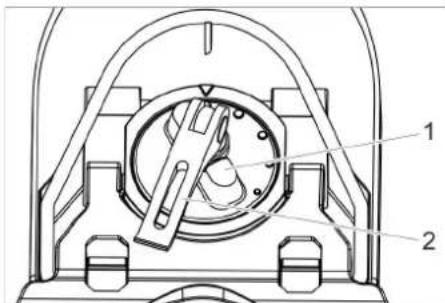
text_image
Technical diagram of a mechanical device with labeled parts 1 and 21 Obrtna ručka
2 Stezna poluga
→ Podignite steznu polugu.
→ Podesiti obrtnu ručku za naginjanje usisne konzole.
→ Pritisnite steznu polugu nadole.
Visina
Sa podešavanjem visine se utiče na savijanje gumica za usisavanje prilikom kontakta sa podom.
natural_image
Technical line drawing of a mechanical assembly with rotating components (no text or symbols)→ Podešavajte obrtne ručke za podešavanje visine dok se ne postigne najbolji rezultat usisavanja.
Podešavanje količine vode
→ Količinu vode podesiti na tasteru za regulisanje prema stepenu zaprljanja podne obloge.
Napomena:
Početne korake čišćenja izvesti sa neznatnom količinom vode. Postepeno povećavati količinu vode sve dok se ne dostigne željeni rezultat čišćenja.
Pogon čišćenja
→ Zauzmite sedeći položaj.
→ Postavite prekidač sa ključem u položaj „1“.
→ Podesite smer vožnje pomoću prekidača za smer vožnje na upravljaču.
→ Okrenuti dugme za radnu brzinu na željenu vrednost.
Brzina se prikazuje na ekranu tokom podešavanja.
Prikaz se vrši u procentima maksimalne brzine.
→ Količnu vode podesite na ventilu za regulaciju.
→ Povucite donju polovinu ručke poluge usisne konzole nagore i čvrsto je držite.
→ Polugu usisne konzole pritisnite nadole. Usisna konzola se spušta i pokreće se usisavanje.
→ Pedalu glave za čišćenje pritisnite nadole/udesno, deblokirajte i pustite da se vrati nagore.
→ Utvrdite brzinu vožnje pritiskom pedale gasa.
Glava za čišćenje se spušta, pokreće se pogon četke i primenjuje se rastvor za čišćenje.
→ Pređite preko površine koja se čisti.
→ Zaustavljanje uređaja: Pustiti pedalu gasa.
Završetak čišćenja
→ Pritisnite pedalu glave za čišćenje nadole da nalegne na svoje mesto.
→ Nastavite da vozite na kratkoj deonici da biste iscedili preostalu vodu.
→ Vucite polugu usisne konzole nagore dok ne nalegne.
natural_image
Technical diagram showing a mechanical assembly with hoses and a foot pusher (no text or symbols)→ Ispustite vodu kroz otvor uređaja za doziranje na ispusnom crevu.
→ Na kraju isperite posudu za prljavu vodu čistom vodom.
natural_image
Line drawing of a mechanical device with attached hoses and a textured base (no text or symbols)→ Prilikom transporta u vozilima, uređaj osigurajte od isklizavanja i prevrtanja u skladu sa važećim smernicama.
Guranje uređaja
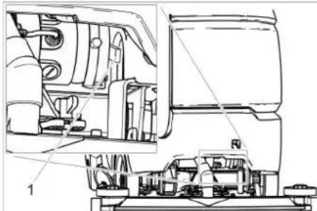
text_image
Technical diagram of a vehicle engine assembly with labeled components and parts1 Poluga za deblokiranje
→ Gurnite ručicu za otpuštanje nagore i povucite uređaj.
△OPASNOST
text_image
Technical diagram of a cleaning machine with labeled parts and exploded view1 Kuka sa urezom
2 Mrežica za skupljanje vlakana
3 Plovak
4 K u ćište plovka
→ Otpustite kuku za zaključavanje.
→ Povucite nadole kućište plovka.
→ Izvadite plovak iz kućišta plovka i očistite ga.
→ Očistite mrežicu za skupljanje vlakana.
→ Sve delove ponovo sklopite obrnutim redosledom.
Čišćenje mrežice za grubu prljavštinu
→ Otvoriti poklopac rezervoara za prljavu vodu.
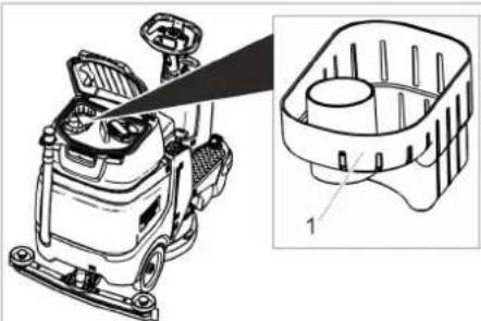
natural_image
Technical line drawing of a cleaning or inspection device with an inset showing internal components (no text or symbols)1 Mrežica za grubu prljavštinu
→ Povucite nagore mrežicu za krupnu prljavštinu.
→ Isperite mrežicu za krupnu prljavštinu ispod tekuće vode.
→ Vratite mrežicu za krupnu prljavštinu u rezervoar za prljavu vodu.
Zamena usisnih gumica
→ Skinuti usisnu konzolu.
→ Odviti zavrtnje na zvezdastim ručicama.

text_image
1. 1. 2. 3.→ Skinuti delove od plastike.
→ Skinuti gumice za usisavanje.
→ Umetnite nove gumice za usisavanje.
→ Postaviti delove od plastike.
→ Zaviti i pričvrstiti zavrtnje sa zvezdastim ručicama.
Zamena pločaste četke
2006/42/EZ (+2009/127/EZ)
2014/30/EU
2000/14/EZ
2014/53/EU (TCU)
Primenjeni harmonizovani standardi
EN 60335-1
EN 60335-2-72
EN 62233: 2008
EN 55012: 2007 + A1: 2009
EN 61000-6-2: 2005
TCU
EN 301 511 V12.5.1
EN 300 440 V2.1.1
EN 300 328 V2.2.2
EN 300 330 V2.1.1
Primenjene nacionalne norme
Potpisnici deluju po nalogu i uz punomoć upravnog odbora.

Chairman of the Board of Management

S. Reiser
Director Regulatory Affairs & Certification
Lice ovlašćeno za dokumentaciju:
S. Reiser
Alfred Kärcher SE & Co.
KG Alfred-Kärcher-Straße 28-40
71364 Winnenden (Nemačka)
Tel.: +49 7195 14-0
text_image
Technical diagram of a cleaning or cleaning machine with numbered parts for identification and assembly reference.text_image
Diagram of a vehicle or road intersection with labeled points and directional indicators1 Разпънка
ВНИМАНИЕ
text_image
Technical diagram of an industrial cleaning machine with labeled components and exploded viewnatural_image
Mechanical assembly diagram showing a lever mechanism with bolts and a cylindrical component (no text or labels)natural_image
Mechanical assembly diagram showing a vehicle with wheels and directional arrows indicating motion (no text or symbols)text_image
Technical diagram of a mechanical device with labeled parts 1 and 21 Въртяща се ръчка
2 Затягаш лост
natural_image
Technical line drawing of a mechanical assembly with springs and rotating components (no text or symbols)natural_image
Technical diagram of a mechanical assembly with hoses and components, no visible text or symbolsnatural_image
Line drawing of a helmet with attached sensors and gear (no text or symbols)text_image
Technical diagram of a vehicle engine assembly with labeled components and parts1 Деблокиращ лост
text_image
Technical diagram of a cleaning or inspection machine with labeled parts including handle, valve, and base componentsnatural_image
Technical line drawing of a car dashboard and steering wheel assembly (no text or symbols)text_image
Technical diagram showing a mechanical assembly with numbered components and directional arrows indicating motion or assembly steps.text_image
Technical diagram of a cleaning or cleaning machine with numbered parts for identification and assembly reference.1 Iste
text_image
Diagram of a vehicle electrical panel layout with labeled terminals and wiring connectionstext_image
Technical diagram of a cleaning or cleaning machine with labeled parts and exploded view1 Akupistik, akupool
2 Akupistik, seadmepool
→ Tömmake akupoolne akupistik ära.
TÄHELEPANU
Kahjustusoht!
Imiotsaku monteerimine
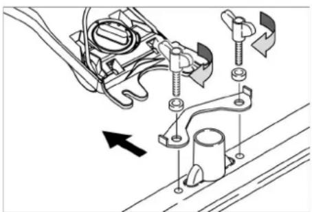
natural_image
Mechanical assembly diagram showing components like bolts, brackets, and a pipe connection (no text or labels)→ Pange imiotsak rippkinnitusse nii, et plekkdetail on rippkinnituse kohal.
→ Keerake tiibmutrid kinni.
→ Pistke imivoolik peale.
Rooliratta seadistamine
natural_image
Mechanical assembly diagram showing a vehicle's wheel and suspension components with directional arrows (no text or labels)→ Vabastage tiibmutter.
→ Keerake imiotsakut.
→ Keerake tiibmutrid kinni.
Kalle
text_image
Technical diagram of a mechanical device with labeled parts 1 and 21 Pöördkäepide
2 Kinnitushoob
natural_image
Technical line drawing of a mechanical assembly with rotating components (no text or symbols)natural_image
Technical diagram showing a mechanical assembly with hoses and a motor base (no text or symbols)natural_image
Line drawing of a mechanical device with hoses and control knobs (no text or symbols)text_image
Technical diagram of a vehicle engine assembly with labeled parts and structural details1 Lahtilukustushoob
text_image
Technical diagram of a cleaning machine with labeled parts and exploded viewnatural_image
Technical line drawing of a car dashboard with an inset showing internal components (no text or symbols)2006/42/EÜ (+2009/127/EÜ)
2014/30/EL
2000/14/EÜ
2014/53/EL (TCU)
Director Regulatory Affairs & Certification
71364 Winnenden (Germany)
Tel: +49 7195 14-0
Fax: +49 7195 14-2212
Winnenden, 2021/11/01
text_image
Technical diagram of a cleaning or cleaning machine with numbered parts for identification and assembly reference.text_image
Diagram of a vehicle interior with labeled components and wiring connections, including plus/minus signs and numbered parts.1 Starplika
BRĪDINĀJUMS
text_image
Technical diagram of a cleaning or cleaning machine with labeled parts and internal components1 Akumulatora spraudnis, akumulatora pusē
2 Akumulatora spraudnis, ierīces pusē
→ Atvienojiet akumulatora spraudni akumulatora pusē.
BRĪDINĀJUMS
Bojājumu risks!
natural_image
Mechanical assembly diagram showing components like bolts, brackets, and a pipe fitting (no text or labels)natural_image
Mechanical assembly diagram showing a vehicle's wheel and suspension components with directional arrows (no text or labels)text_image
Technical diagram of a mechanical device with labeled parts 1 and 21 G r o z āms regulators
2 Spriegošanas svira
natural_image
Technical line drawing of a mechanical assembly with rotating components (no text or symbols)natural_image
Technical diagram showing a mechanical assembly with hoses and a foot pedal (no text or symbols)natural_image
Line drawing of a mechanical device with attached components (no text or symbols)text_image
Technical diagram of a vehicle engine assembly with labeled components and partstext_image
Technical diagram of a cleaning machine with labeled parts including handle, valve, and component 4natural_image
Technical line drawing of a car dashboard with an inset showing internal components (no text or symbols)text_image
Technical diagram showing a mechanical assembly with numbered components and directional arrows indicating motion or assembly steps.Chairman of the Board of Management

S. Reiser
Director Regulatory Affairs & Certification
71364 Winnenden (Germany)
Tel.: +49 7195 14-0
Fakss: +49 7195 14-2212
Winnenden, 2021/11/01
text_image
Technical diagram of a cleaning or cleaning machine with numbered parts for identification and assembly reference.text_image
Diagram of a vehicle or road intersection with labeled points and directional arrows indicating movement or flow.1 Tarpiklis
DÉMESIO
text_image
Technical diagram of a cleaning or cleaning machine with labeled parts and an inset view showing internal components.natural_image
Mechanical assembly diagram showing components like bolts, brackets, and a pipe fitting (no text or labels)natural_image
Mechanical assembly diagram showing a vehicle's wheel and suspension components with directional arrows (no text or labels)→ Atlaisvinkite sparnines veržles.
→ Pasukite siurbimo rėmelį.
→ Tvirtai prisukite sparnines veržles.
Pakreipimas
Jei siurbimo efektas néra pakankamas, si- urbimo rémelj galima pakreipti.
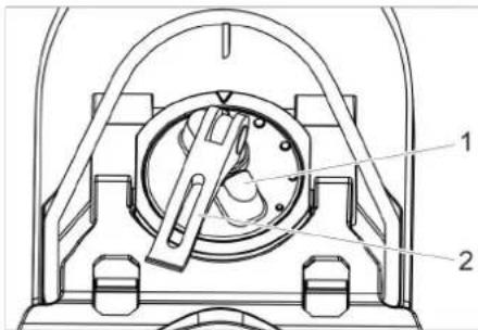
text_image
Technical diagram of a mechanical device with labeled parts 1 and 21 Pasukama rankena
2 |tempimo svirtis
natural_image
Technical line drawing of a mechanical assembly with rotating components (no text or symbols)natural_image
Technical diagram showing a mechanical assembly with hoses and a foot pedal (no text or symbols)natural_image
Line drawing of a mechanical device with hoses and brackets (no text or symbols)text_image
Technical diagram of a mechanical assembly with labeled components and cross-sectional viewstext_image
Technical diagram of a cleaning machine with labeled parts including handle, valve, and base components1 Fiksavimo kablys
natural_image
Technical line drawing of a car interior with a zoomed-in view showing internal components (no text or symbols)
Chairman of the Board of Management
Director Regulatory Affairs & Certification
text_image
Technical diagram of a cleaning or cleaning machine with numbered parts for identification and assembly reference.text_image
Diagram of a vehicle or road intersection with labeled points and directional indicatorstext_image
Technical diagram of an industrial cleaning or cleaning machine with labeled components and a close-up inset showing internal wiring connections.natural_image
Mechanical assembly diagram showing components like bolts, springs, and a pipe fitting (no text or labels)natural_image
Mechanical assembly diagram showing fluid flow and component placement (no text or labels)text_image
Technical diagram of a mechanical device with labeled parts 1 and 2natural_image
Technical line drawing of a mechanical assembly with spring and chain components (no text or symbols)natural_image
Mechanical assembly diagram showing a pipe connection to a motor or vehicle chassis (no text or symbols present)natural_image
Line drawing of a helmet with attached straps and accessories (no text or symbols)natural_image
Technical line drawing of a mechanical assembly with labeled components (no readable text or symbols)text_image
Technical diagram of a cleaning machine with labeled parts including spray gun, bucket, and filter unitnatural_image
Technical line drawing of a cleaning machine with an inset showing its internal components (no text or symbols present)Chairman of the Board of Management
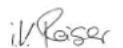
S. Reiser
Director Regulatory Affairs & Certification
text_image
Technical diagram of a cleaning or cleaning machine with numbered parts for identification and assembly reference.1 시트
2 폐수 탱크 뚜껑
3 폐수 탱크용 미터링 장치
4 조항획
5경음기 버튼
6 주행방향 스위치
7 작업속도 회전버튼
8키스위치
9디스플레이
10 진공바 손잡이
11 물량 조절버튼
12 주행 페달
13 브러시 교환 폐달
14 디스크 브리시
15 클리닝 헤드
16 청수 레벨표시장
17 진공바 *
18 폐수 탱크
19 폐수 비출 호스
text_image
Diagram of a vehicle electrical panel layout with labeled terminals and wiring connections1 스페이서
주의
text_image
Technical diagram of a cleaning or cleaning machine with labeled parts and an inset view showing internal components.1 배터리 플러그, 배터리 측
2 베터리 플러그,장비 측
natural_image
Mechanical assembly diagram showing a lever mechanism with no visible text or symbolsnatural_image
Mechanical assembly diagram showing a vehicle's suspension system with rotating components and directional arrows (no text or labels)text_image
Technical diagram of a mechanical device with labeled parts 1 and 21 회신 손잡이
2 클램핑 손잡이
natural_image
Technical line drawing of a mechanical assembly with rotating components (no text or symbols)natural_image
Technical diagram showing a mechanical assembly with hoses and a motor base (no text or symbols)natural_image
Line drawing of a mechanical device with attached components (no text or symbols)text_image
Technical diagram of a mechanical assembly with labeled parts, showing internal components and structural details.1 해제 손잡이
text_image
Technical diagram of a cleaning machine with labeled parts and exploded view1 잠금 후크
2 보풀 필터
3플로터
4 풀로터 하우징
natural_image
Technical line drawing of a car dashboard with an inset showing internal components (no text or symbols)1 큰 오염물 체
71364 Winnenden (Germany)
Tel.: +49 7195 14-0
Fax: +49 7195 14-2212
Winnenden, 2021/11/01
text_image
Technical diagram of a cleaning or cleaning machine with numbered parts for identification and assembly reference.1 座椅
2 污水箱盖罩
3 污水计量装置
4 方向盘
5喇叭按钮
6 行驶方向开关
7 工作速度旋钮
8 钥匙开关
9 显示屏
10 吸水扒手柄
11 用水量调节钮
12 油门踏板
13 刷子更换用踏板
14 刷盘
15 清洁头
16 清水液位表
17 吸尘架 *
18 污水箱
19 污水排放软管
20 用于倾斜吸尘架的转动手柄
21 用于固定吸尘架的翼形螺母
22 抽吸软管
23 清水箱封盖,水箱配备清水过滤器
24 升/降清洗头的踏板
25 清水箱盖子
清水加注口
26 电池插头
27 方向盘高度调节
* 不属于供货范围
颜色标记
- 清洁过程的操作元件为黄色。
- 保养和检修的操作元件为浅灰色。
设备上的标志
text_image
Diagram of a vehicle or road intersection with labeled points and directional arrows indicating movement or flow.1 间隔垫片
注意
损坏危险。注意电极是否正确。
text_image
Technical diagram of an industrial cleaning or cleaning machine with labeled components and exploded viewnatural_image
Mechanical assembly diagram showing components like bolts, clamps, and a pipe connection (no text or labels)natural_image
Mechanical assembly diagram showing a vehicle's suspension system with rotating components and directional arrows (no text or labels)→ 松开翼形螺母。
→ 转动吸尘架。
→ 拧紧翼形螺母。
倾斜度
text_image
Technical diagram of a mechanical device with labeled parts 1 and 21 旋转手柄
2 拉紧杆
natural_image
Technical line drawing of a mechanical assembly with springs and rotating components (no text or symbols)natural_image
Technical diagram showing a mechanical assembly with hoses and a base plate, no visible text or symbolsnatural_image
Line drawing of a mechanical device with attached components (no text or symbols)text_image
Technical diagram of a mechanical assembly with labeled parts, showing internal components and structural details.1 解锁杆
→ 将释放杆向上按并推动设备。
危险
text_image
Technical diagram of a cleaning machine with labeled parts including handle, spray bottle, and bucket1 卡扣
2 细滤网
3 浮子
4 浮子室
natural_image
Technical line drawing of a car dashboard with an inset showing internal components (no text or symbols)1 粗滤网
text_image
Technical diagram of a cleaning or cleaning machine with numbered parts for identification and assembly reference.1 座位
2 污水箱盖
3 污水計量装置
4 方向盤
5 喇叭按鈕
6 行駛方向開關
7 工作速度旋钮
8 鑰匙開闢
9 顯示幕
10 吸水扒操控杆
11 用水量調節鈕
12 駕駛踏板
13 刷子更换用踏板
14 刷盤
15 清洗頭
16 清水液位表
17 吸水條*
18 污水箱
19 污水排放软管
20 用於傾斜吸水條的轉動手柄
21 用於固定吸水條的翼形螺帽
22 抽吸软管
23 清水箱封蓋,水箱配備清水過濾器
24 升/降清洗頭的踏板
25 淡水箱蓋
淡水加注口
26 電池插頭
27 方向盤高度調節
* 未包含在供货範圍內
顏色標誌
- 用於清洗過程的操作元件為黃色。
- 用於保養和服務的操作元件為淺灰色。
設備上的符號
text_image
Diagram of a vehicle or road intersection with labeled points and directional arrows indicating movement or flow.1 間隔墊片
注意
損壞危險。注意電極是否正確。
text_image
Technical diagram of a cleaning or cleaning machine with labeled parts and internal wiring connectionsnatural_image
Mechanical assembly diagram showing components like bolts, springs, and a valve with an arrow indicating direction (no text or labels present)natural_image
Mechanical assembly diagram showing a vehicle's suspension system with arrows indicating motion direction (no text or labels)text_image
Technical diagram of a mechanical device with labeled parts 1 and 21 轉動手柄
2 拉緊桿
natural_image
Technical line drawing of a mechanical assembly with springs and rotating components (no text or symbols)natural_image
Technical diagram of a mechanical assembly with hoses and a connector (no text or symbols)→ 打開排放軟管上的計量裝置排水。
→ 然後用清水沖洗污水箱。
倒空清水箱
natural_image
Line drawing of a helmet with attached sensors and gear (no text or symbols)text_image
Technical diagram of a mechanical assembly with labeled components, showing internal components and parts of a vehicle or machine.1 釋放桿
text_image
Technical diagram of a cleaning machine with labeled parts including spray gun, bucket, and tank1 卜鉤
2 絨毛過濾器
3 浮子
4 浮子室
→ 鬆開卡鉤。
→ 向下拉出浮子室。
→ 將浮子從浮子室中取出,然後清洗。
→ 清洗細濾網。
→ 按照相反的順序重新組裝所有部件。
清洗粗濾網
→ 打開污水箱蓋。
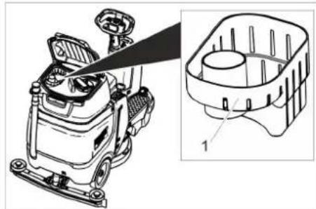
natural_image
Technical line drawing of a cleaning machine with an inset showing its internal components (no text or symbols present)1 粗濾網
→ 將粗大污染物濾網向上拉出。
→ 將粗大污染物濾網放到自來水下沖洗。
→ 將粗大污染物濾網重新裝到污水箱上。
更换吸水膠條
→ 取下吸水條。
→ 旋出星形手柄。
text_image
1. 1. 2. 3.Chairman of the Board of Management
S. Reiser Director Regulatory Affairs & Certification
文檔全權代表:
S. Reiser
Alfred Kärcher SE & Co. KG
Winnenden, 2021/11/01
text_image
Technical diagram of a cleaning or cleaning machine with numbered parts for identification and assembly reference.text_image
Diagram of a vehicle or road intersection with labeled points and directional arrows indicating movement paths.1 Peruang
PERHATIAN
text_image
Technical diagram of a cleaning or cleaning machine with labeled parts and exploded view1 Palam bateri, sisi bateri
2 Palam bateri, sisi peranti
→ Keluarkan samping bateri plag bateri.
PERHATIAN
Risiko kerosakan!
natural_image
Mechanical assembly diagram showing components like bolts, brackets, and a pipe connection (no text or labels)→ Pasang rasuk sedutan di gantungan rasuk sedutan, sehingga helaian borang berada di gantungan.
→ Ketatkan nat wing.
→ Pasang hos penyedut.
Tetapkan stereng
natural_image
Mechanical assembly diagram showing motor components and directional arrows (no text or labels)→ Longgarkan nat wing.
→ Putar rasuk sedutan.
→ Ketatkan nat wing.
Kecondongan
text_image
Technical diagram of a mechanical device with labeled components 1 and 21 Pemegang putar
2 Tuil pelepas
natural_image
Technical line drawing of a mechanical assembly with rotating components and springs (no text or symbols)natural_image
Technical diagram showing a mechanical assembly with hoses and a control panel (no text or symbols)natural_image
Line drawing of a mechanical device with attached hoses and brackets (no text or symbols)text_image
Technical diagram of a vehicle engine compartment with labeled parts and structural details1 Tuil pelepasan
→ Tekan tuil pelepasan dan dorong peranti.
BAHAYA
Bahaya kemalangan kerana kekurangan fungsi brek.
text_image
Technical diagram of a cleaning machine with labeled parts including handle, spray bottle, and cylindrical component1 Cangkuk selak
2 Penapis bulu halus
3 Apungan
4 Perumah apungan
1 Cangkuk selak 2 Penapis bulu halus 3 Apungan 4 Perumah apungan
natural_image
Technical illustration of a car dashboard with an inset showing internal components (no text or symbols)1 Penapis kotoran kasar
text_image
Technical diagram showing mechanical assembly with numbered components and directional arrows indicating motion or flow.→ Tarik keluar bahagian plastik.
→ Tarik mulut sedutan.
→ Pasang mulut sedutan baru.
→ Tangguhkan bahagian plastik.
→ Pasang dan ketatkan pemegang
bintang.
Ganti berus cakera
Chairman of the Board of Management
S. Reiser
Director Regulatory Affairs & Certification
71364 Winnenden (Germany)
Tel.: +49 7195 14-0
Winnenden, 1/11/2021
ملحقات
text_image
Technical diagram of a cleaning or inspection device with numbered parts labeled 1 to 41 خطاف الشikit
2 مصفاة الزغب
3 عوامة
4 علبة العوامة
natural_image
Technical line drawing of a vehicle's internal components, showing engine, dashboard, and gearbox assembly (no text or labels)natural_image
Technical line drawing of a mechanical device with no visible text or symbolsnatural_image
Technical line drawing of a mechanical assembly with labeled components (no readable text or symbols)1 دراع التحرير
natural_image
Technical diagram of a mechanical assembly with hoses and components, no visible text or symbolstext_image
Technical diagram of a mechanical device with labeled parts 1 and 2natural_image
Technical line drawing of a mechanical assembly with rotating components (no text or symbols)natural_image
Mechanical assembly diagram showing a vehicle with rotating components and directional arrows indicating motion (no text or symbols)natural_image
Mechanical assembly diagram showing components like bolts, brackets, and a cylindrical component (no text or labels)text_image
Technical diagram of an industrial cleaning machine with labeled parts and exploded viewtext_image
Diagram of a vehicle electrical panel layout with labeled terminals and wiring connections1 مبعدات
تنيه
text_image
Technical diagram of a cleaning or cleaning machine with numbered parts for identification and assembly reference.| Visual Modelling |  |
| Visual Modelling (English) |  |
| Visual Modelling (Chinese) |  |
| Visual Modelling (English) |  |
تجهز اختياري **
الثميز اللوني
natural_image
Black silhouette of a hand giving a thumbs-up gesture (no text or symbols)THANK YOU!
MERCI! DANKE! iGRACIAS!

Register your product and benefit from many advantages.
www.kaercher.com/welcome


Rate your product and tell us your opinion.
natural_image
Icon showing a gear and wrench inside a square frame (no text or symbols)www.kaercher.com/dealersearch
Alfred Kärcher SE & Co. KG
Alfred-Kärcher-Str. 28-40
71364 Winnenden (Germany)
Tel.: +49 7195 14-0
Fax: +49 7195 14-2212