B 50 W Bp Pack - Scrubber Kärcher - Free user manual and instructions
Find the device manual for free B 50 W Bp Pack Kärcher in PDF.
| Product type | Scrubber (floor cleaner) |
| Brand | Kärcher |
| Model | B 50 W Bp Pack |
| Dimensions (L x W x H) | 1375 x 542 x 1082 mm (head D51) |
| Empty weight | 195 kg |
| Permissible total weight | 245 kg |
| Power supply | Battery 24 V (lead) or 25.6 V (Li-ion); integrated charger 100-240 V |
| Dirty water tank capacity | 50 L |
| Detergent tank capacity | 3 L (Dose option) |
| Working width | 510 mm (head D51) |
| Max. travel speed | 6 km/h |
| Practical area performance | 1380 m²/h (head D51) |
| Traction motor power | 130 W |
| Suction turbine power | 250 W |
| Brush drive power | 800 W |
| Rated voltage | 24 V (lead) / 25.6 V (Li-ion) |
| Battery capacity | 76 to 115 Ah (lead) / 80 Ah (Li-ion) |
| Protection type | IPX3 |
| Sound level (acoustic pressure) | 65 dB(A) |
| Operating temperature range | 5 to 40 °C |
| Maximum water temperature | 50 °C |
| Maximum working incline | 2% |
| Main functions | Flat floor water cleaning, dirty water suction, self-propelled, ECO/Normal/Intensive programs, smartphone connectivity via Bluetooth |
| Maintenance and cleaning | Regular cleaning of dirty water tank, filters, suction lips and brushes; tank rinsing |
| Safety | Emergency stop by removing the intelligent key, dead man's safety switch, battery safety devices |
| Spare parts and repairability | Kärcher original accessories and parts, after-sales service |
Frequently Asked Questions - B 50 W Bp Pack Kärcher
User questions about B 50 W Bp Pack Kärcher
0 question about this device. Answer the ones you know or ask your own.
Ask a new question about this device
Download the instructions for your Scrubber in PDF format for free! Find your manual B 50 W Bp Pack - Kärcher and take your electronic device back in hand. On this page are published all the documents necessary for the use of your device. B 50 W Bp Pack by Kärcher.
USER MANUAL B 50 W Bp Pack Kärcher
natural_image
3D rendering of a Kürcher industrial cleaning machine (no visible text or symbols on the device body)Deutsch 6
English 14
Français 23
Italiano 31
Español 40
Português 49
Nederlands 58
Türkçe 67
Svenska 75
Suomi 84
Norsk 92
Dansk 100
Eesti 109
Latviešu 117
Lietuviškai 126
Polski 135
Magyar 144
Čeština 152
Slovenčina 161
Slovenščina 170
Românește 178
Hrvatski 187
Srpski 196
Ελληνικά 204
Русский 214
Українська 224
Български 233
中文 243
繁體中文 250
한국이 258
Bahasa Melayu 266
日本語 275
العربية 292
B 50 W Bp +D60+Rinse+AF
B 50 W Bp Pack 115Ah+D51
B 50 W Bp Pack 115Ah+D51+Dose+Rinse+AF
B 50 W Bp Pack 115Ah+D51+Rinse+AF
B 50 W Bp Pack 115Ah+D60
B 50 W Bp Pack 115Ah+D60+Dose+Rinse+AF
B 50 W Bp Pack 115Ah+D60+Rinse+Autofill
B 50 W Bp Pack 115Ah+R55
B 50 W Bp Pack 115Ah+R55+Dose+Rinse+AF
B 50 W Bp Pack 115Ah+R55+Rinse+AF
B 50 W Bp Pack 80Ah Li+D51
B 50 W Bp Pack 80Ah Li+D51+Dose+Rinse+AF
B 50 W Bp Pack 80Ah Li+D51+FC+Do+Ri+AF
B 50 W Bp Pack 80Ah Li+D51+Rinse+Autofill
B 50 W Bp Pack 80Ah Li+D60
B 50 W Bp Pack 80Ah Li+D60+Dose+Rinse+AF
B 50 W Bp Pack 80Ah Li+D60+FC+Do+Ri+AF
B 50 W Bp Pack 80Ah Li+D60+Rinse+Autofill
B 50 W Bp Pack 80Ah Li+R55
B 50 W Bp Pack 80Ah Li+R55+Dose+Rinse+AF
B 50 W Bp Pack 80Ah Li+R55+FC+Do+Ri+AF
B 50 W Bp Pack 80Ah Li+R55+Rinse+Autofill
B 50 W Bp Pack 80Ah+D51
B 50 W Bp Pack 80Ah+D51+Rinse+Autofill
B 50 W Bp+D51
B 50 W Bp+D51+Dose+Rinse+Autofill
B 50 W Bp+D51+Rinse+Autofill
B 50 W Bp+D60
B 50 W Bp+D60+Dose+Rinse+Autofill
B 50 W Bp+R55
B 50 W Bp+R55+Dose+Rinse+Autofill
B 50 W Bp+R55+Rinse+Autofill
text_image
Technical diagram of a KARCHER cleaning machine with numbered parts and exploded views
text_image
B ① ② ③ ④ ⑤ ⑥ ⑦ ⑧ ⑨ ⑩ ⑪ ⑫ ⑬ ⑭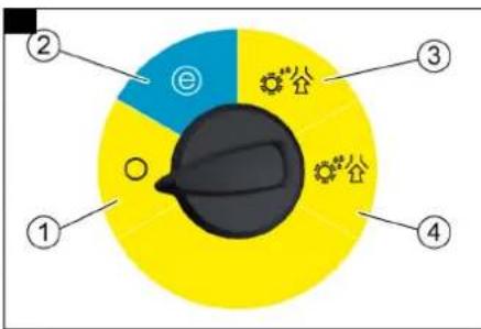
text_image
② ③ ① ④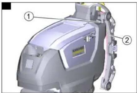
text_image
Technical diagram of a cleaning or cleaning device with labeled parts ① and ②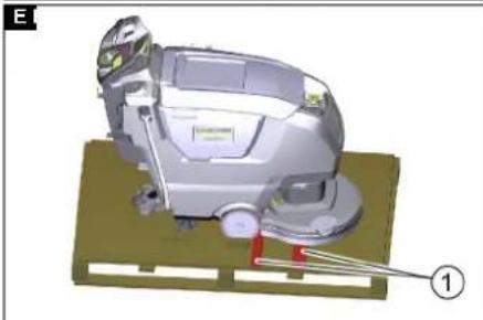
natural_image
3D rendering of a cleaning or cleaning machine with a lever and base plate (no visible text or symbols)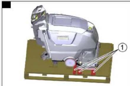
natural_image
3D mechanical assembly diagram showing a motor or robotic device with labeled parts (no readable text or symbols)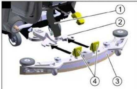
text_image
Technical diagram of a vehicle suspension system with numbered components and directional arrows indicating movement or assembly.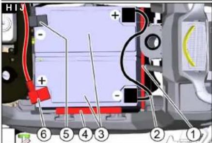
text_image
H13 + - ⑥ ⑤ ④ ③ ② ①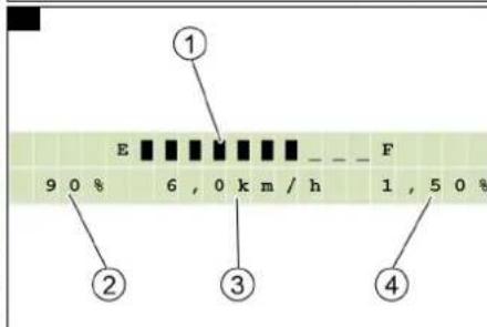
text_image
① E F 9 0 % 6 , 0 km / h 1 , 5 0 % ② ③ ④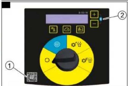
text_image
B 50 W ① ②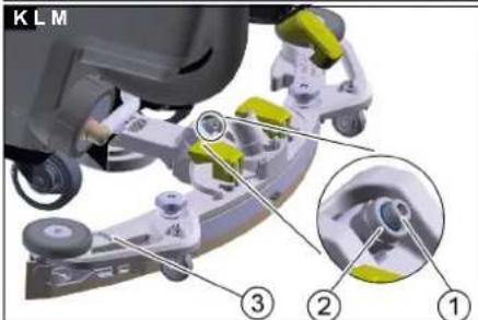
text_image
K L M ③ ② ①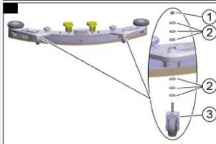
text_image
Technical diagram of a mechanical assembly with numbered components and alignment lines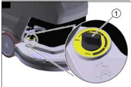
text_image
① MIN MLC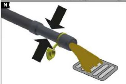
natural_image
3D diagram of a cable with a yellow tip and black arrows indicating direction, no text or symbols present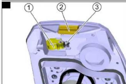
text_image
Diagram of a device interior with numbered components, likely illustrating a mechanical or electronic assembly.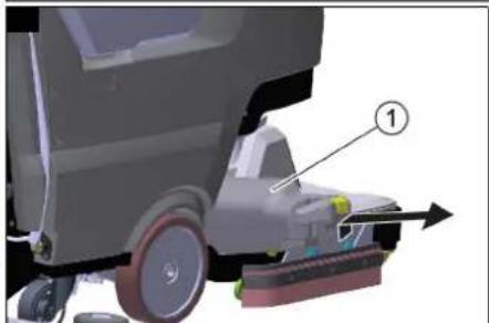
natural_image
3D diagram of a cleaning or cleaning vehicle with labeled component (1), showing wheel, foot, and tool path (no text or symbols beyond label)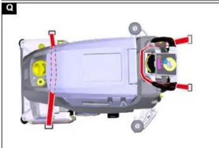
natural_image
Top-down schematic of a car's internal components with red and yellow parts, no visible text or symbols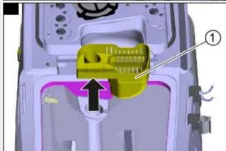
natural_image
3D mechanical component diagram showing a yellow plastic housing with an arrow pointing to a component (no text or symbols present)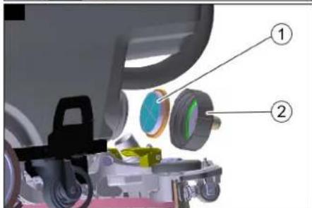
text_image
Technical diagram of a car interior with labeled components, showing parts numbered 1 and 2.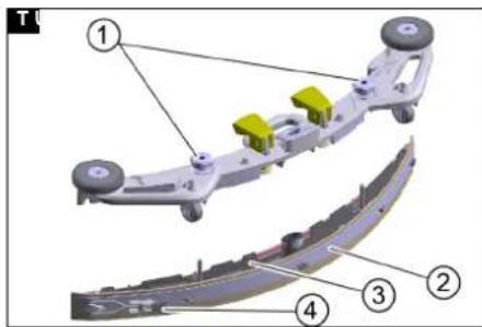
text_image
Technical diagram of a mechanical assembly with numbered components, likely for assembly or maintenance instructions.
text_image
Diagram of four labeled parts of a curved mechanical component, showing progressive assembly from top to bottom.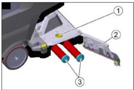
text_image
Technical diagram of a mechanical assembly with numbered components, likely for assembly or maintenance instructions.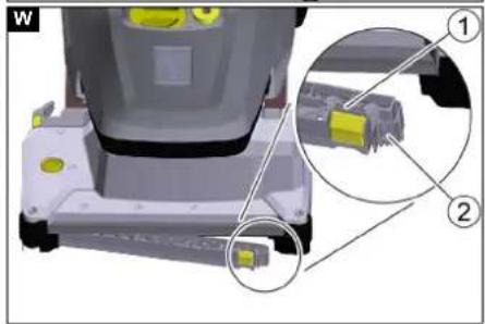
natural_image
3D mechanical assembly diagram showing a component with highlighted parts and an inset view of a connector (no text or symbols present)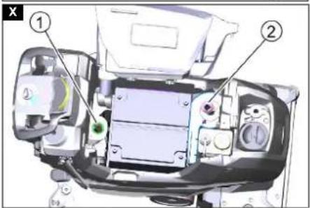
text_image
Technical diagram of a vehicle engine compartment with numbered parts labeled ① and ②Inhalt
text_image
Diagram of an electronic device rear panel with numbered labels pointing to specific ports or functions.EN IEC 61000-6-2: 2005
TCU
EN 301 511 V12.5.1
EN 300 440 V2.1.1
EN 300 328 V2.2.2
EN 300 330 V2.

H. Jenner
Chairman of the Board of Management
S. Reiser
Director Regulatory Affairs & Certification
71364 Winnenden (Germany)
Tel.: +49 7195 14-0
Fax: +49 7195 14-2212
Winnenden, 2021/08/01
Contents
General notes 14
Function 14
Intended use 14
Environmental protection 14
Accessories and spare parts.... 14
Scope of delivery 14
Safety instructions.... 14
Device description.... 15
Intelligent Key 16
Installation.... 16
Initial startup.... 16
Switching on the device 17
Pairing with a smartphone 17
Maintenance requests.... 17
Operation 17
Transport 18
Storage 18
Care and maintenance.... 18
Troubleshooting guide.... 19
Accessories.... 21
Technical data 21
Warranty.... 22
Declaration of Conformity 22
General notes
Read these original operating instructions and the enclosed safety instructions before using the device for the first
accordingly.
Keep both books for future reference or for future owners.
Function
This scouring and vacuum machine is used for wet cleaning of level floors.
The device can be adjusted to suit the respective cleaning task by adjusting the water quantity, detergent volume and travel speed.
The device can be adapted to the respective cleaning task by selecting a suitable cleaning program.
The working width and the capacity of the fresh and waste water tanks (see chapter "Technical data") enable effective cleaning with a long working time.
The device is self-propelled.
The batteries can be charged using the built-in charger. The charger can be operated with a voltage of 100-240 V.
Note
The device can be equipped with various accessories to suit the respective cleaning task. Request a copy of our catalogue or visit our Internet website at www.kaercher.com.
Intended use
This device is suitable for commercial and industrial use, e.g. in hotels, schools, hospitals, factories, shops, offices, and rental companies. Use the device only in accordance with the information in these operating instructions.
- The device may only be used for cleaning smooth surfaces that are insensitive to water and polishing
- The device is not suitable for cleaning frozen floors (e.g. in cold stores).
- The device is designed for cleaning indoor floors or covered areas.
- The device is suitable for use in the temperature range 5-40 °C.
- The device must be stored in a frost-free location.
- The device is not suitable for use in potentially explosive environments.
- No flammable gases, undiluted acids or solvents may be taken up with the device. These include petrol, paint thinner or heating oil, which can form explosive mixtures in the suction air turbulence. Do not use acetone, undiluted acids or solvents, as these corrode the materials used on the device.
- Reactive metal dusts (e.g. aluminium, magnesium, zinc) in conjunction with highly alkaline or acidic detergents form explosive gases.
- The device is not intended for cleaning public traffic routes.
- Take the permissible surface load of the floor into account (see chapter Technical data).
- The device may only be fitted with original accessories and spare parts.
- When using chargers or batteries, only the components approved in the operating instructions may be used. A different combination must be approved by the responsible charger supplier and/or battery supplier.
Environmental protection
The packing materials can be recycled. Please dispose of packaging in accordance with the environmental regulations.
Electrical and electronic devices contain valuable, recyclable materials and often components such as batteries, rechargeable batteries or oil,
which - if handled or disposed of incorrectly - can pose a potential danger to human health and the environment. However, these components are required for the correct operation of the device. Devices marked by this symbol are not allowed to be disposed of together with the household rubbish.
Notes on the content materials (REACH)
Current information on content materials can be found at: www.kaercher.de/REACH
Accessories and spare parts
Only use original accessories and original spare parts. They ensure that the appliance will run fault-free and safely. Information on accessories and spare parts can be found at www.kaercher.com.
Scope of delivery
Check the contents for completeness when unpacking. If any accessories are missing or in the event of any shipping damage, please notify your dealer.
Safety instructions
Before using the device for the first time, read and observe these operating instructions and the accompanying brochure: Safety instructions for brush cleaning devices, No. 5.956-251.0.
△WARNING
The device can tip over
Risk of injury
Do not operate the device on sloping surfaces.
△WARNING
Risk of accident due to incorrect operation
People can be injured.
Operators must be properly trained on how to use this machine.
The device may only be operated when the hood and all covers are closed.
Safety devices
△CAUTION
Missing or modified safety devices!
Safety devices are provided for your own protection.
Do not bypass, remove or render ineffective any safety devices.
Emergency off
Note
Remove the Intelligent Key for an immediate shutdown (emergency off).
Driving lever
The travel drive and the brush drive switch off when the driving lever is released.
Symbols on the device

△DANGER
Charging process
Electric shock
Do not remove the pole protection caps from the battery poles.
Ensure correct installation

ATTENTION
Risk of damage
Water damages the suction turbine
Make sure that no water enters an opening marked in this way.
Notes on the battery (rechargeable battery) and charger
The Li-Ion version has built-in lithium-ion batteries. These are subject to special criteria. Removal and installation as well as testing of defective batteries may only be carried out by Kärcher customer service or a qualified specialist.
For storage and transport instructions, please contact your Kärcher Customer Service.
△DANGER
Modifications and alterations to the device are not per- mitted.
You must not open the battery, there is a danger of a short circuit. Irritating vapours or corrosive liquids can also escape.
Do not expose the battery to strong sunlight, heat or fire. There is a danger of explosion.
Do not operate the charger in an explosion-hazard environment.
Do not use a dirty or wet charger.
Ensure sufficient ventilation during the charging process.
Danger of explosion. Keep naked flames away from the battery or the battery charging room, and do not generate sparks or smoke in the vicinity of a battery of a battery charging room.
Danger of explosion. Do not place any tools or objects on the battery, i.e. on the end poles and cell connectors. ⚠ WARNING
Check the device and the mains cable for damage before each use. Do not use damaged devices and have damaged parts repaired by qualified personnel only.
Keep children away from batteries and charger. Do not charge damaged batteries. Have damaged batteries replaced by Kärcher customer service.
Do not throw a defective battery in the household rubbish. Inform Kärcher Customer Service.
Avoid contact with fluid leaking from defective batteries. In case of accidental contact, rinse the liquid with water. In case of contact with the eyes, consult a doctor as well.
△CAUTION
Be sure to observe these operating instructions. Adhere to the recommendations of the legislature regarding the handling of batteries.
The mains voltage must match the voltage indicated on the type plate of the device.
Use the charger for charging approved battery packs only. Operate the battery only with this device. It is forbidden and dangerous to use it for other purposes.
Warning symbols
Observe the following warnings when handling the batteries:

Observe notes in the instructions for the battery, on the battery and in these operating instructions.

Wear eye protection.

Keep acids and batteries away from children.
Risk of explosion
Fire, sparks, open flames and smoking are prohibited.
Risk of acid burns

First aid.
Warning

Disposal
Do not throw batteries in the bin.
Device description
Overview of the device
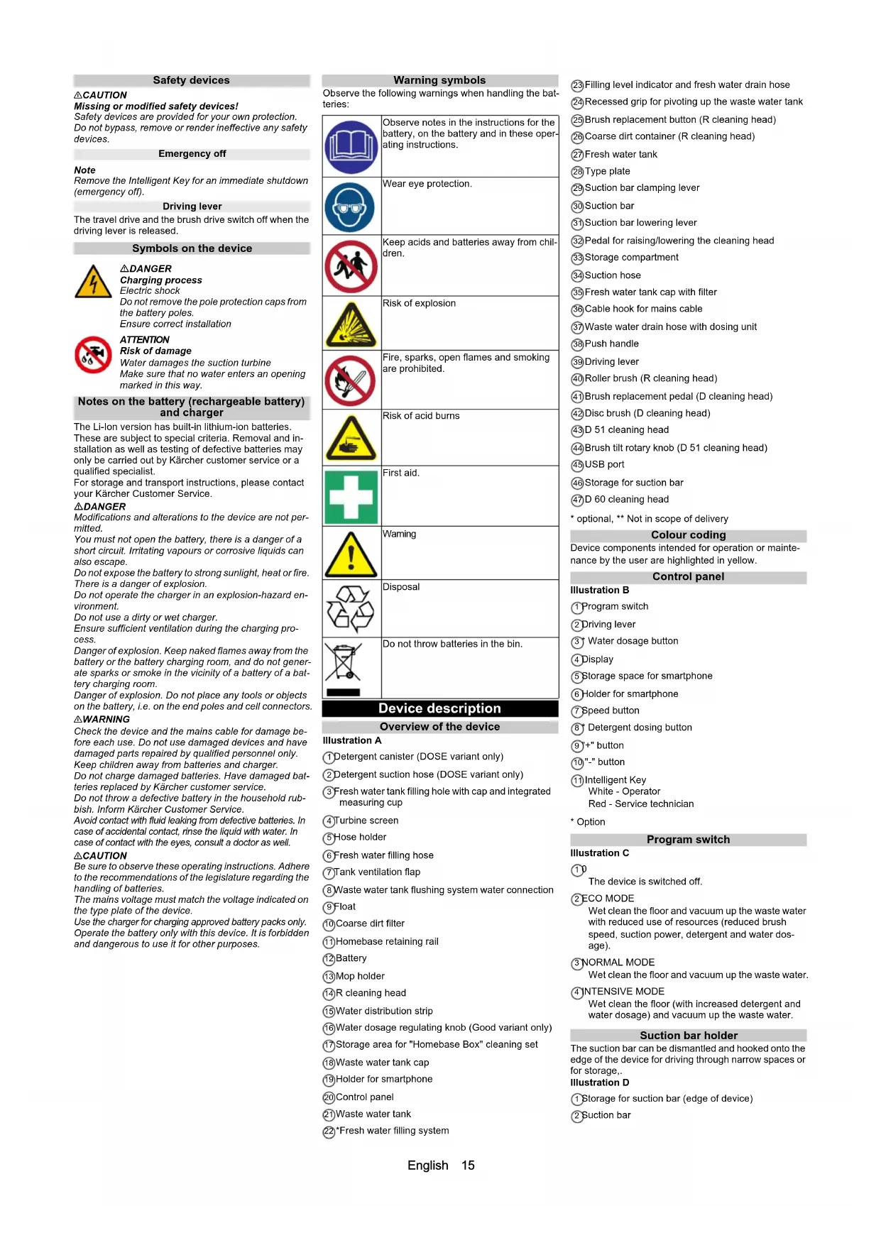
Illustration A
①Detergent canister (DOSE variant only)
②Detergent suction hose (DOSE variant only)
③ Fresh water tank filling hole with cap and integrated measuring cup
④ Turbine screen
⑤ Hose holder
⑥Fresh water filling hose
⑦Tank ventilation flap
⑧ Waste water tank flushing system water connection
⑨Float
⑩ Coarse dirt filter
⑪Homebase retaining rail
12Battery
13Mop holder
⑭R cleaning head
⑮Water distribution strip
⑯Water dosage regulating knob (Good variant only)
⑰ Storage area for "Homebase Box" cleaning set
⑱ Waste water tank cap
⑲Holder for smartphone
20Control panel
②1 Waste water tank
22*Fresh water filling system
②3 Filling level indicator and fresh water drain hose
⑳Recessed grip for pivoting up the waste water tank
⑲Brush replacement button (R cleaning head)
②6 Coarse dirt container (R cleaning head)
⑳Fresh water tank
⑳Type plate
29 Suction bar clamping lever
30 Suction bar
③1 Suction bar lowering lever
③2 Pedal for raising/lowering the cleaning head
③3 Storage compartment
③4Suction hose
③5 Fresh water tank cap with filter
③6 Cable hook for mains cable
③7 Waste water drain hose with dosing unit
③8 Push handle
⑲Driving lever
④0 Roller brush (R cleaning head)
④1 Brush replacement pedal (D cleaning head)
④2Disc brush (D cleaning head)
④3D 51 cleaning head
④4 Brush tilt rotary knob (D 51 cleaning head)
④5 USB port
④6 Storage for suction bar
④7D 60 cleaning head
* optional, ** Not in scope of delivery
Colour coding
Device components intended for operation or maintenance by the user are highlighted in yellow.
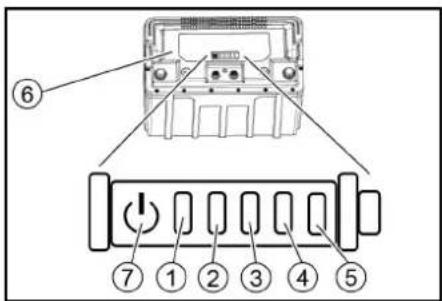
Control panel
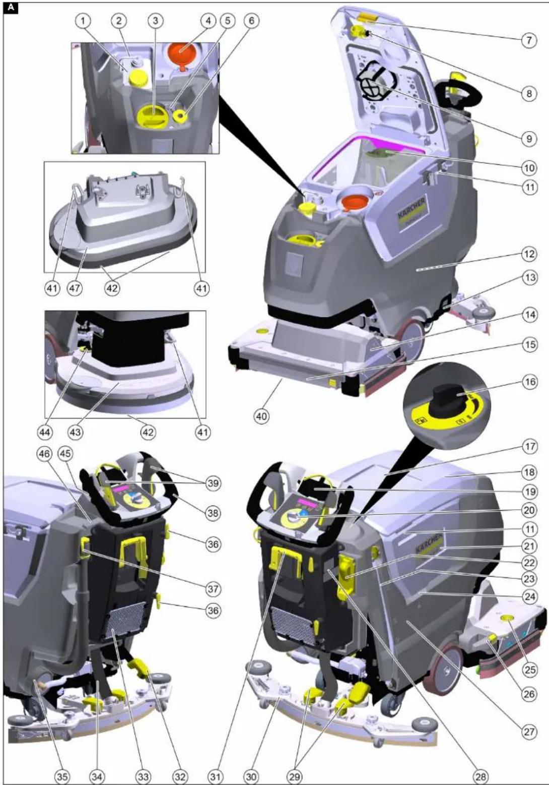
Illustration B
① Program switch
②Driving lever
③ Water dosage button
④ Display
⑤ Storage space for smartphone
⑥Holder for smartphone
⑦ Speed button
⑧ Detergent dosing button
⑨"+" button
⑩ "-" button
⑪ Intelligent Key
White - Operator
Red - Service technician
* Option
Program switch
Illustration C
①0
The device is switched off.
② ECO MODE
Wet clean the floor and vacuum up the waste water with reduced use of resources (reduced brush speed, suction power, detergent and water dosage).
③NORMAL MODE
Wet clean the floor and vacuum up the waste water.
④ INTENSIVE MODE
Wet clean the floor (with increased detergent and water dosage) and vacuum up the waste water.
Suction bar holder
The suction bar can be dismantled and hooked onto the edge of the device for driving through narrow spaces or for storage.
Illustration D
① Storage for suction bar (edge of device)
② Suction bar
Symbols on the device

Mains cable for charger

Lashing point

* Mop holder

* Fill with fresh water

Fresh water tank filling level 25%

Fresh water tank filling level 50%

Fresh water tank filling level 100%

Brush replacement pedal (BD)
Brush replacement button (BR)

Adjust brush tilt (D 51 cleaning head only)

Drain for waste water
Drain for fresh water

Remove the coarse dirt container

Raise/lower the cleaning head
Drive forwards
Drive in reverse
Intelligent Key
The Intelligent Key is used to switch on the device and for enabling certain device functions.
- Yellow: Operator
The device can be used. All settings for the cleaning programs enabled for this key via the smartphone app may be changed. - Grey: Foreman
The device can be used. All settings for the cleaning programs available for the device may be changed.
Installation
Unloading the device
- Unscrew the screws on the transport locks.
Illustration E
Illustration F
①Transport lock
2. Remove the transport locks.
3. Push the device forwards from the pallet.
Installing the suction bar
- Pivot both clamping levers upwards.
Illustration G
① Suction hose
②Suction bar suspension
③ Suction bar
④ Clamping lever
-
Insert the suction bar in the suction bar mount.
-
Pivot both clamping levers downwards.
Installing the brushes
- Only with BD variant: Install the disc brush before initial startup (see chapter Maintenance work).
Note
With variant BR, the brushes are installed.
- Install the brush (see chapter Maintenance work).
Batteries
Recommended batteries
ATTENTION
Risk of damage
Batteries may only be replaced with batteries of the same technology.
Lead batteries must not be replaced by Li-ion batteries Li-ion batteries must not be replaced by lead batteries.
Lead batteries
| Description Order no. | |
| Set 76 Ah - maintenance-free, 24 V 2 | 815-099.0 |
| Set 105 Ah - maintenance-free, 24 V | 2.815-100.0 |
| Set 115Ah - maintenance-free, 24 V 2 | 815-091.0 |
| Set 80 Ah - maintenance-free, 24 V 2 | 815-090.0 |
The device requires 2 batteries.
Li-ion batteries:
| Description Order no. | |
| 80 Ah, 25.6 V 6.654-454.0 |
The device requires 1 battery.
Maximum battery dimensions
| Length 350 | |
| Width | 355 |
| Height | 290 |
Installing and connecting batteries
Note
In the case of the device variant with Li-Ion battery, the battery is already installed and connected. A Li-Ion battery may only be installed or replaced by the customer service.
△DANGER
Danger of fire and explosion!
Do not place tools or similar items on the battery. Risk of short-circuit and explosion.
Smoking and naked flames must be strictly avoided. Rooms where batteries are charged must have good ventilation as highly explosive gas is emitted during charging.
△CAUTION
Removing and installing the batteries
Unstable machine position
Ensure that the machine is positioned stably when removing and installing the batteries.
ATTENTION
Incorrect connection polarity
Destruction of the control electronics
Take care to ensure the correct polarity when connecting the batteries.
ATTENTION
Deep discharge
Risk of damage
Charge the batteries before starting the device.
- Push the device approx. 2 m forwards so that the steering rollers point to the rear.
- Hold the waste water tank by the recessed grip and pivot it sideways and upwards.
- Fit the batteries in the pan.
- Connect the batteries:
a Fit the spacers.
Illustration H
① Spacers 340x40x10 (9.763-222.0)
②Connection cable
③Battery
480 Ah: Spacers 295x94x10 (5.642-034.0)
15 Ah: Spacers 295x94x23 (5.642-033.0)
⑤Connection cable to the battery (-)
⑥Connection cable to the battery (+)
b Connect both batteries with the connection cable. c Clamp the connection cables to the (+) and (-) battery terminals that are still free.
- Pivot the waste water tank downwards.
Activating the Li-Ion battery
Li-lon batteries are delivered in transport mode and must be activated before initial startup of the device.
- Charge the battery (see "Initial startup/Charging the battery"), this will end the transport mode.
Removing the battery
△CAUTION
Removing and installing the batteries
Unstable machine position
Ensure that the machine is positioned stably when removing and installing the batteries.
△WARNING
Device tipping over
Risk of injury, risk of damage
Only remove the batteries when a cleaning head is attached to the device.
- Set the program selection switch to "0".
- Remove the Intelligent Key.
- Empty the waste water tank.
- Push the device approx. 2 m forwards so that the steering rollers point to the rear.
- Hold the waste water tank by the recessed grip and pivot it sideways and upwards.
- Disconnect the cable from the negative terminal of the battery.
- Disconnect the remaining cables from the batteries.
- In the case of Li-Ion batteries, also disconnect the two round plugs on the battery.
- Remove the spacers.
- Remove the batteries
- Dispose of the used batteries in accordance with the applicable regulations.
Initial startup
Setting the charging characteristic
Before the initial startup, after a service reset or when changing to a different battery type, it is essential to set the charging characteristic.
△DANGER
Danger due to the device inadvertently starting up Risk of injury
Disconnect the spark plug connector or disconnect the battery before performing any work on the device.
ATTENTION
Risk of damage to the battery
The service life and charging capacity of the battery can be affected by an incorrect charging characteristic. Make sure that the battery characteristic curve that matches the battery is selected in the machine.
The currently selected battery characteristic curve can be seen on the display or via the app in the "Device status" area during charging.
Note
The charging characteristic can only be adjusted by Kärcher Service.
Battery characteristics are available for the following batteries:
• EXIDE GF12105V
• HOPPECKE TB115
• EXIDE GF12076V
• EXIDE FF12080W
• TROJAN 27TMX
• HOPPECKE TB80
• ZENITH L120185
Note
To enable the use of other batteries as well, a custom battery characteristic curve can be created by the Kärcher service department.
Charging the battery
△DANGER
Inappropriate use of the charger
Electric shock
Adhere to the mains voltage and fuse values specified on the device type plate.
Only use the charger in dry rooms with sufficient ventilation.
The built-in charger is electronically controlled and suitable for all recommended batteries, it ends the charging process automatically.
Note
The corresponding charging characteristic must be set for each type of battery installed.
The installed battery is shown in the display when charging.
The average charging time is approx. 10-15 hours.
The device cannot be used during the charging process.
Note
The device has deep discharge protection, i.e. the brush motor and turbine are switched off automatically in operation when the permitted minimum capacity level is reached.
- Drive the device directly to the charger and do not drive on slopes.
- Plug the mains plug on the power cable into the mains socket.
- Charge until the display shows full charge.
Low-maintenance batteries (wet batteries)
△DANGER
Danger of burns due to acid leakage!
Only fill the battery with water when it is discharged. When handling battery acid, use safety goggles and immediately rinse out any acid splashes on the skin or clothing with water.
ATTENTION
Risk of damage to the batteries!
Using water with additives will void the battery's warranty. Top up the batteries using only distilled or desalinated water (EN 50272-T3).
Do not use any foreign additives or touch-up agents.
1. Add distilled water one hour before the charging process comes to an end. Observe the correct acid level according to the battery label. All cells must produce gas at the end of the charging process.
Switching on the device
- Insert the Intelligent Key into the control panel.
- Set the program switch to a cleaning program. The display shows the following, one after the other:
- Kärcher Logo
• Time until next service in hours
• Battery status and operating hours - Software version
- Operating display Illustration I
① Battery charge state
② Set water dosage (only for devices with an electric water valve)
③ Set speed
④ Set detergent dosage (only for DOSE device variant)
The device is ready for operation.
Pairing with a smartphone
The "Machine Connect" smartphone app connected to the device can be used to perform advanced device functions:
- Set the type of cleaning head
- Set the maximum transport speed
- Switch the USB port off/on
- Set the after-running time of the brush(es)
- Set the after-running time of the suction
- Switch the speed-dependent water dosing on/off
- Manage the permissions of the yellow Intelligent Key
- Restore the factory settings
Note
The possible functions depend on the device version.
- Scan the QR code on the device with your smartphone. Illustration J
① QR code
②Bluetooth® symbol
- Install the "Machine Connect" app on the smartphone and start it.
- Insert the Intelligent Key into the control panel.
- Press the "+" and "-" keys on the control panel of the device simultaneously for 3 seconds.
Note
The Bluetooth® symbol on the control panel flashes during the pairing process.
5. Follow the pairing instructions of the app on the smartphone.
6. The functions of the app are explained on the smartphone.
Note
The Bluetooth symbol lights up continuously when the smartphone is paired with the device.
Note
The mobile phone can be connected to the USB port of the device to charge the battery.
Maintenance requests
After a certain operating time has elapsed, the display prompts to perform various maintenance activities:
| Call Interval (hours) | |
| CLEANING VACUUM FILTER 10 | |
| CLEANING SUCTION BAR 20 | |
| CLEANING FILTER WATER 50 | |
| CHECK BRUSH WEAR 100 | |
| CHECK SUCTION LIP 100 |
- Carry out the indicated maintenance activity.
- Press any button on the control panel to confirm. The prompt is reset and displayed again after the interval has elapsed.
Operation
△DANGER
Risks during operation
Risk of injury
Release the driving lever in the case of danger.
Loss of stability
Risk of injury
Operate the pedal to raise/lower the cleaning head with one foot only. Keep the other foot firmly and securely on the floor.
Filling with operating materials
Filling with fresh water
- Open the fresh water tank cap
- Fill fresh water (max. 50 °C) to the lower edge of the filling nozzle.
Note: The fresh water hose can be clamped with the hose holder during filling.
- Close the fresh water tank lock.
Filling with fresh water via the filling hose
- Pull the filling hose out of the device.
- Connect the end of the filling hose to a water tap.
- Remove the fresh water tank cap
- Open the water supply (water temperature maximum 50 °C).
- Observe the filling level of the fresh water tank through the filling hole.
- Close the water inlet when the filling level reaches the lower edge of the filling nozzle.
- Fit the fresh water tank lock
- Disconnect the filling hose from the water tap.
- Push the filling hose into the device.
Filling with fresh water via the filling system
- Connect the water hose to the connection nozzle of the filling system (maximum water temperature 50 °C).
- Open the water inlet.
- Monitor the device, the automatic filling system interrupts the water supply when the fresh water tank is full.
- Close the water inlet.
- Remove the water hose.
Notes on detergents
△WARNING
Unsuitable detergents
Health risk, damage to the device
Use only recommended detergents. The operator carries all increased risks relating to operational safety and increased risk of accidents if using other detergents.
Use only detergents free of solvents, salt and hydrofluoric acid.
Adhere to the safety instructions stated on the detergent packaging.
Note
Do not use heavily foaming detergent.
Recommended detergents
| Application | Detergent |
| Maintenance cleaning of all water-resistant floors | CA 50 CRM 756 |
| Maintenance cleaning with care components | RM 746RM 780 |
| Maintenance cleaning and basic cleaning of industrial floors | RM 69 |
| Maintenance cleaning of glossy coverings | RM 755 |
| Maintenance cleaning and basic cleaning of fine stone tiles | RM 753 |
| Maintenance cleaning and basic cleaning of acid-resistant coverings | RM 751 |
| Cleaning and disinfection | RM 732 |
| Basic cleaning of all alkali-resistant floor coverings | RM 752 |
| Basic cleaning and de-coating of alkali-sensitive floors | RM 754 |
Addition of detergent with a dosing device
Only with DOSE variant:
Detergent is added to the fresh water on the way to the cleaning head by a dosing device.
- Fill the detergent into the detergent canister.
Note
A maximum of 3% detergent can be added with the dosing device. If the dosage is higher, the detergent must be added to the fresh water tank.
ATTENTION
Danger of clogging
When adding detergent to the fresh water tank, the detergent can dry out and disrupt the function of the dosing device.
Rinse the device with clear water after adding the detergent to the fresh water tank: Select a cleaning program with water application, set the water quantity to the highest value, set the detergent dosage to 0.
Adding detergent without a dosing device
- Fill the detergent into the fresh water tank.
Note
The cap of the filling hole has a scale inside and can be used to measure the detergent volume.
Setting the detergent dosage
With the DOSE device variant, the detergent is added to the fresh water on its way to the cleaning head.
The detergent dosage can be set separately for each cleaning programme.
- Insert the Intelligent Key into the control panel.
- Select the cleaning programme to be set with the programme switch.
- Press the Detergent dosing button.
- Set the desired detergent dosage with the "+" and "-" buttons.
- To accept the setting, either wait 3 seconds or press one of the other buttons.
Adjusting the water quantity
- Adjust the water quantity according to the degree of soiling of the floor covering.
Note
Perform initial cleaning tests with a low water volume. Increase the water volume step by step until achieving the desired cleaning result.
Note
The cleaning head continues operating without a liquid supply if the fresh water tank is empty.
Manual water valve
A device with a manual water valve is equipped with a regulating knob for water dosage to the right of the control panel.
- Turn the water dosage regulating knob to the desired value.
Note
The brush irrigation is only active when the cleaning head is lowered and the driving lever is actuated.
Electric water valve
A device with an electric water valve is equipped with a water dosage button on the control panel.
The water dosage can be set separately for each cleaning programme.
- Insert the Intelligent Key into the control panel.
- Select the cleaning programme to be set with the programme switch.
- Press the water dosage button
- Set the desired water dosage with the "+" and "-" buttons.
- To accept the setting, either wait 3 seconds or press one of the other buttons.
Note
The brush irrigation is only active when the cleaning head is lowered and the driving lever is actuated.
Adjusting the inclination of the suction bar
The inclination must be adjusted so that the suction lips of the suction bar make even contact with the floor over the entire length of the suction bar.
- Park the device on a surface without a slope.
- Select the "Suction" program.
- Drive the device a small distance forwards. The suction bar is lowered.
- Read the spirit level.
Illustration K
① Screw
②Nut
③ Spirit level
-
Release the M 12 nut while holding the M 10 hexagon head screw with an open-end wrench.
-
Adjust the screw so that the spirit level indicator is between the two lines.
- Tighten the M 12 nut while holding the M 10 hexagon head screw with an open-end wrench.
- To check the new setting, move the device forward a short distance in suction mode with the suction bar lowered and observe the spirit level. Repeat the adjustment process if necessary.
Adjusting the height
The height adjustment affects the bending of the suction lips on contact with the floor.
Note
Standard setting: 3 washers above, 3 washers below the suction bar.
Uneven floor: 5 washers above, 1 washer below the suction bar.
Very smooth floor: 1 washer above, 5 washers below the suction bar.
- Unscrew the nuts. Illustration L
①Nut
② Washer
③ Spacer roller with holder
- Place the desired number of washers between the suction bar and the spacer roller.
- Fit the remaining unused washers above the spacer roller.
- Screw on the nut and tighten.
- Repeat the entire procedure at the second spacer roller.
Note
Set both spacer rollers to the same height.
Adjusting the side pull of the brush
(Only with D 51 cleaning head)
If the device pulls to one side during cleaning, this can be remedied by adjusting the brush tilt.
Note
After changing the brush/pad, it may be necessary to re-adjust the side pull.
- Adjust the brush tilt rotary knob until the device moves straight ahead. Illustration M
① Brush inclination rotary knob
Switching on the device
- Assume a seated position.
- Turn the key-operated switch to "1".
The display shows the following one after the other: - Period of time until the next after-sales Customer Service
- Software version, control panel
- Battery charge state and number of operating hours
Driving
Note
The device is constructed so that the cleaning head protrudes to the right. This makes it possible to work clearly and close to the edge.
- Insert the Intelligent Key.
- Pivot the suction bar lowering lever upwards.
- Press the raise /lower cleaning head pedal down and latch it towards the right.
- Set the program switch to the desired program.
- Drive the device.
a Push the driving lever forward. The device moves forward.
b Push the driving lever backwards. The device moves in reverse.
Note
The device moves only when the driving lever is moved by 5°.
6. Release the driving lever.
The device stops.
Cleaning
ATTENTION
Risk of damage
The floor covering can be damaged if the device is operated on the same spot for a long time.
Do not operate the device continuously on the same point.
- Insert the Intelligent Key.
- Set the program switch to the desired cleaning program.
- Pivot the lever downwards to lower the suction bar.
- Press the cleaning head raise/lower pedal down, move it to the left and let it go up.
- Push the driving lever forward and drive over the area to be cleaned.
Note
When the waste water tank is full, the float switch closes the suction opening and the suction turbine runs at a higher speed. In this case, switch off the vacuuming function and drive to the location for emptying the waste water tank.
Finishing operation
Finishing cleaning
- Turn the water quantity regulating knob to "OFF" (not for the DOSE version).
- Release the driving lever.
- Press the raise /lower cleaning head pedal down and latch it towards the right.
- Continue moving a short distance.
The residual water is vacuumed up.
- Pivot the suction bar lowering lever upwards.
Draining the waste water
△WARNING
Environmental pollution!
Environmental pollution due to improper disposal in waste water.
Observe the local waste water treatment regulations.
- Remove the drain hose from the support and lower it over a suitable collecting device. Illustration N
- Press the dosing unit together or kink the hose.
- Open the dosing unit cover.
- Drain the waste water. Regulate the water volume by pressing or kinking.
- Rinse the waste water tank with clear water.
Waste water tank flushing system
- Remove the waste water drain hose from the holder and lower it over a suitable collecting device.
- Open the dosing unit cover at the drain hose.
- Open the waste water tank cover.
- Pull the flexible cap off the flushing system.
- Connect the water hose to the flushing system. Illustration O
①Lock
②Tank ventilation flap
③ Flushing system water connection
- Close the waste water tank cover.
- Open the water supply and flush the waste water tank for about 30 seconds.
If necessary, repeat the flushing process 2 - 3 times - Close the water supply and disconnect the hose from the device.
- Reattach the flexible cap to the water inlet of the flushing system.
- Close the cover of the waste water tank. Press the tank ventilation flap in so that a gap remains open and the waste water tank can dry.
- Push the waste water drain hose into the holder and closed the cover of the dosing device.
Draining fresh water at the cap
- Open the fresh water tank cap.
- Drain the fresh water.
- Clean the filter
- Fit the fresh water tank cap.
Draining fresh water via the filling level indicator
- Remove the filling level indicator hose from the holder and pivot it down.
- Reattach the hose.
Emptying the coarse dirt container
(R cleaning head only)
- Lift the coarse dirt container and pull it out. Illustration P
①Coarse dirt container
2. Empty the coarse dirt container and clean it if necessary.
3. Reinstall the coarse dirt container.
Parking the device
- Turn the program switch to position "0".
- Remove the Intelligent Key.
- Press the raise/lower cleaning head lever down and latch it towards the right.
- Pivot the suction bar lowering lever upwards.
- Secure the device against rolling away.
- Close the cover of the waste water tank. Press the tank ventilation flap in so that it engages in the groove of the fresh water tank so that the waste water tank can dry.
- Charge the battery if necessary.
Transport
△DANGER
Driving on slopes
Risk of injury
Observe the maximum permissible gradient when operating the device on slopes for loading and unloading purposes (see chapter "Technical data"). Drive slowly.
△CAUTION
Failure to observe the weight
Risk of injury and damage
Be aware of the weight of the device during transport. Only load the device with the dirt and fresh water tanks empty.
Only load the device with the assistance of another person or by using the drive.
- Press the raise/lower cleaning head pedal down and latch it towards the right.
- Remove the brushes to avoid damage.
- Remove the suction bar from the device.
- When transporting in vehicles, secure the device against slipping and tipping over using the transport eyelets according to the respectively applicable guidelines.
Illustration Q
Storage
△CAUTION
Failure to observe the weight
Risk of injury and damage
Be aware of the weight of the device during storage.
ATTENTION
Frost
Destruction of the device through freezing water Drain all water from the device.
Store the device in a frost-free location.
• This device may only be stored indoors.
- Fully charge the batteries before storing them for a long period.
- Fully charge the batteries at least every month during storage.
Care and maintenance
△DANGER
Inadvertently starting up device
Risk of injury
Turn the program switch to the "0" position.
Remove the Intelligent Key prior to all work on the device.
Pull out the charger mains plug.
● Drain and dispose of the waste water and fresh water.
Safety inspection/maintenance contract
You can agree on regular safety inspections or close a maintenance contract with your dealer. Please seek advice on this.
Maintenance intervals
Each time after use
ATTENTION
Improper cleaning
Risk of damage.
Do not spray the device with water.
Do not use aggressive cleaning agents.
- Drain the waste water.
- Clean the waste water tank with the waste water tank flushing system.
- Remove the coarse dirt filter from the waste water tank and clean it.
- Check the turbine screen, remove it if necessary and clean it.
- Clean the exterior of the device using a damp cloth, wetted with a mild washing lye.
- Only with R cleaning head: Remove the coarse dirt container and empty it.
- Only with R cleaning head: Clean the water distribution strip.
- Check the suction lips, check for wear and replace if necessary.
- Clean the squeegee blades on the cleaning head, check for wear and replace if necessary.
- Clean the brushes, check for wear and replace if necessary.
- Close the cover of the waste water tank. Press the tank ventilation flap in so that a gap remains open and the waste water tank can dry.
- Charge the battery.
Lead-acid battery:
- If the charging state of the battery is below 50%, charge the battery fully and without interruption.
- If the charging state of the battery is above 50%, only recharge the battery if the entire operating duration will be required when next used.
Li-Ion battery:
● Recharge as necessary.
Monthly
● Empty and flush the fresh water tank.
- Clean the fresh water filter.
- Clean the float.
- For a temporarily shut-down device with lead-acid battery: Perform equalization charging of the battery.
- Check battery poles for oxidation, brush off if necessary. Make sure the connection cables are firmly in place.
- Clean the seals between the waste water tank and the cover, check for leaks and replace if necessary.
- Only with R cleaning head: Clean the brush tunnel.
- Only with R cleaning head: Pull the water distribution strip off the cleaning head and clean the water channel.
- Check the acid density of the cells if the lead batteries are not maintenance-free.
- For longer downtime periods, shut the device down with fully charged batteries. Fully charge the battery at least once a month.
Annually
- Have the prescribed inspection performed by Customer Service.
Maintenance work
Cleaning the coarse dirt filter
- Open the waste water tank cover. Illustration R
① Coarse dirt filter
-
Pull the coarse dirt filter upwards and off.
-
Rinse off the coarse dirt filter under running water.
-
Reinsert the coarse dirt filter into the waste water tank.
Cleaning the fresh water filter
-
Drain the fresh water.
-
Unscrew the fresh water tank cap. Illustration S
① Fresh water filter
②Fresh water tank lock
-
Pull out the fresh water filter and rinse with clear water.
-
Insert the fresh water filter.
-
Fit the fresh water tank lock.
Turn over or replace the worn suction lips
The suction lips must be turned over or replaced when worn out.
The suction lips can be turned 3 times until all 4 edges are worn.
-
Remove the suction bar.
-
Unscrew the star handles.
Illustration T
①Star grip
②Strap
③Inner part of the suction bar
④Tension lock
3. Pull out the inner part of the suction bar.
4. Open the tension lock.
5. Remove the strap.
6. Release the suction lips from the inner part.
Illustration U
① Squeegee blade
②Support lip
③Inner part of the suction bar
④ Strap
-
Press the turned or new suction lips onto the knobs of the inner part of the suction bar.
-
Attach the strap
-
Push the inner part of the suction bar into the upper part.
-
Screw in and tighten the star handles.
Replacing the disc brush
Note
Replace the disc brushes when the bristle length has reached 10 mm.
-
Press the raise/lower cleaning head lever down and latch it towards the right.
-
Push the brush replacement pedal down.
-
Pull the disc brush sideways and out from underneath the cleaning head.
-
Hold the new disc brush under the cleaning head, then press upwards and latch it into position.
Replacing the roller brushes
Note
Replace the roller brushes when the bristle length has reached 10 mm.
-
Press the raise/lower cleaning head lever down and latch it towards the right.
-
Press the Brush replacement button.
Illustration V
① Brush replacement button
② Bearing cover
③ Roller brush
-
Pivot the bearing cover to the right.
-
Pull out the roller brushes.
-
Position the new front roller brush in the bearings.
-
Position the new rear roller brush in the bearings.
-
Pivot back the bearing cover and latch it into place.
Cleaning the water distribution strip
- Push the locking lever to the left and simultaneously pull the water distribution strip away from the cleaning head.
Illustration W
①Water distribution strip
②Locking lever
-
Remove the water distribution strip from the cleaning head.
-
Clean the water distribution strip.
-
Fit the left side of the strip into the cleaning head.
-
Pivot the water distribution strip towards the cleaning head and latch it into place on the right-hand side.
Animated maintenance work
Troubleshooting guide
△DANGER
Inadvertently starting up device
Risk of injury
Set the program switch to "0" prior to all work on the device.
Remove the Intelligent Key prior to all work on the device.
Pull out the charger mains plug.
- Drain and dispose of the waste water and fresh water.
- Contact Customer Service in the case of malfunctions that cannot be corrected using this table.
Malfunctions without information shown on the display
| Malfunction Rectification | |
| The device cannot be started 1. Insert | the Intelligent Key.2. Set the program switch to the desired program.3. Operate the driving lever.4. Check the batteries and charge if necessary.5. Check that the battery terminals are correctly connected. |
| The water quantity is insufficient | 1. Check the fresh water filling level and fill the tank if necessary.2. Increase the water quantity.a DOSE version: Set the water quantity with the water quantity button on the control panel.b Other versions: Set the water quantity using the water quantity regulating knob.3. Clean the fresh water filter.4. R cleaning head: Clean the water distribution strip.5. Check the hoses for clogging and clean if necessary. |
| The suction performance is too low | 1. Set the programme switch to NORMAL or INTENSIVE MODE.2. Set the suction power in the app to HIGH.3. Shut down the device and drain the waste water.4. Check that the cap on the waste water drain hose is closed.5. Clean the seals between the waste water tank and the cover, check for leaks and replace if necessary.6. Check the turbine screen for soiling and clean if necessary.7. Clean the suction lips at the suction bar, turn over or replace if necessary.8. Check the suction hose for clogging and clean if necessary.9. Check the suction hose for leaks and replace if necessary.10. Check the adjustment of the suction bar.11. Hold the waste water tank by the recessed grip and pivot it sideways and upwards.a Check the seal on the suction turbine.b Check the seal on the suction duct.Illustration X1Suction duct seal2Suction turbine seal |
| The cleaning results are unsatisfactory | 1. Reduce the driving speed.2. Select a more intensive cleaning programme.3. Check the brushes for wear and replace if necessary.4. Check the brush for soiling and clean if necessary.5. Check the suitability of the brush type and detergent used.6. Check the water supply.7. Increase the water quantity.8. Use the two-step method: In the first pass clean without suction, in the second pass clean with suction. |
| Malfunction Rectification | |
| The suction turbine runs at an increased speed | 1. Drain the waste water.2. Clean the float.3. Check the fluff filter and clean if necessary.4. Check the suction hose for clogging and clean if necessary.5. Check the suction bar for clogging and remove any clogging if necessary |
| The brushes do not rotate | 1. Check if the brushes are blocked by a foreign body and remove the foreign body if necessary.2. Set the program switch to the desired program.3. Lower the cleaning head. |
| The device vibrates during cleaning | 1. Check that the brush(es) are correctly installed.2. Use a softer brush.3. Renew the brush. |
| DOSE version only: The detergent dosing device does not work | 1. Check the detergent level in the detergent canister.2. Increase the detergent dosage.3. Check the connection of the detergent hose to the detergent canister.4. Clean the filter in the detergent canister.5. Check the check valve in the hose to the cleaning head for blockage.6. Check the hoses for leaks.7. Check the functionality of the detergent pump. |
| The waste water drain hose is clogged | 1. Open the dosing unit cover at the drain hose.2. Pull the suction hose off the suction bar and close it by hand.3. Set the program switch to a programme with suction.The blockage is sucked out of the drain hose into the waste water tank. |
Malfunctions with information shown on the display
| Malfunction Cause Rectification | ||
| INSERT KIK | No intelligent key inserted. | Insert an intelligent key. |
| INCORRECT KIK The inserted Intelligent | Key does not authorise the execution of the selected function. | Use a different Intelligent Key.Possibly have the Intelligent Key used activated (depending on the case). |
| NO AUTHORISATION The inserted Intel | ligent Key does not authorise the execution of the selected function. | Use a different Intelligent Key.Possibly have the Intelligent Key used activated (depending on the case). |
| RELEASE HANDLE SWITCH! | When the device is switched on, a driving lever is operated. | Release both driving levers. |
| BATTERY LEVEL LOW | The battery is almost empty. The cleaning functions of the device are automatically switched off. | Drive the device to the charging station and charge the battery. |
| BATTERY EMPTY | The battery is empty. The cleaning functions and the travel drive are switched off. | Switch off the device, wait briefly and switch it on again. The drive to the charging station. If necessary, push it to the charging station when it is switched off. Charge the battery. |
| WATER FLOW FAULT | The electric water valve is defective. | Contact customer service. |
| DRIVE MOT. OVERL. | The current consumption of the driving motor is too high. | Check the travel drive train for foreign objects.Find a path with a lower gradient.Switch off the device, wait briefly, switch the device on again. |
| DRIVE MOT. BLOCK. | The driving motor is blocked. | Check the travel drive train for foreign objects.Jack up each drive wheel individually and check whether it can be turned. |
Li-Ion battery status indicator
text_image
Diagram of an electrical switchgear with numbered components and labeled parts①Status LED
②Indicator LED 1
③Indicator LED 2
④Indicator LED 3
⑤Indicator LED 4
⑥Battery
⑦Button
- Press the button for 5 seconds.
• No LED lights up: Charge the battery. - The status LED lights up green: Together, all 5 LEDs indicate the battery charge state.
- The status LED lights up red: The indicator LEDs indicate a malfunction. Malfunctions described in the following table can be remedied by the user. Contact KÄRCHER Customer Service in the case of fault displays that are not described above.
| (1) | (2) | (3) | (4) | (5) | Cause | Rectification |
| red | - | - | - | - | The battery is too hot. | Allow the battery to cool down. |
| red | - | - | - | green | The battery management system is too hot. | Allow the battery to cool down. |
| red | - | - | green | - | The battery is too cold for charging. | Move the device to a warmer place and wait until the battery has warmed up. |
| red | - | - | green | green | The current consumption during charging is too high. | Unplug the mains plug of the charger. Wait 10 seconds. Reinsert the mains plug. If the malfunction is displayed again, replace the charger. |
| The current consumption of the device is too high. | Switch off the device. If the malfunction occurs again after switching on, look for the fault in the device. | |||||
| red | - | green | - | green | Short-circuit. | Check all battery connections. |
| red | - | green | green | - | Cell voltage too low during discharge. | Charge the battery. |
| red | - | green | green | green | Cell voltage too high during charging. | Discharge the battery to 20% remaining capacity. Then charge the battery. |
| red | green | - | - | green | The battery voltage is too low. | Charge the battery. |
| red | green | - | green | - | Malfunction during charging process. | Unplug the mains plug of the charger. Wait 10 seconds. Reinsert the mains plug. If the malfunction is displayed again, replace the charger. |
| red | green | - | green | green | ||
| red | green | green | - | - | The battery is too cold to output power. | Move the device to a warmer place and wait until the battery has warmed up. |
| red | green | green | green | - | Power output malfunction. | Switch off the device. If the malfunction persists, contact Customer Service. |
Accessories
Cleaning head with roller brushes accessories
A: Packaging unit, B: Quantity required by the device
| Description Part no. Description A B | ||||
| Roller brush, red (medium, standard) 4.035-184.0 Red | standard roller brush for maintenance cleaning. 1 2 | |||
| Roller brush, white (soft) 4.762-409.0 White roller brush | for cleaning sensitive floor coverings. 1 2 | |||
| Roller brush, orange (high / low) | 4.762-410.0 | Orange roller brush with high-low structure for particularly effective cleaning of structured floor coverings. | 1 | 2 |
| Roller brush, green (hard) | 4.762-411.0 | Green abrasive roller brush for basic cleaning and for removing strongly adhering dirt. | 1 | 2 |
| Roller brush, black (very hard) | 4.762-412.0 | Black, particularly abrasive roller brush for basic cleaning of insensitive floor coverings with particularly adherent dirt. | 1 | 2 |
| Microfiber roller | 4.114-010.0 | Ideal for fine stone tiles. Microfibre roller for reliable and gentle removal of grey film. | 1 | 2 |
| Pad roller shaft | 4.762-415.0 | Pad roller shaft made of aluminium to accommodate roller pads or microfibre rollers. | 1 | 2 |
| Roller pad, yellow (soft) | 6.369-732.0 | Yellow roller pad for cleaning and polishing non-textured floor coverings. | 20 | 40 |
| Roller pad, red (medium) | 6.369-734.0 | Red standard roller pad for maintenance cleaning of non-textured floor coverings. | 20 | 40 |
| Roller pad, green (hard) | 6.369-733.0 | Green abrasive roller pad for basic cleaning as well as for removing strongly adhering soiling on non-structured floor coverings. | 20 | 40 |
Cleaning head with disc brushes accessories
A: Packaging unit, B: Quantity required by the device
| Description | Part no. | Description | A | B | ||
| D 51 | D 60 | D 51 | D 60 | |||
| Disc brush, natural colour (soft) | 4.905-027.0 | 4.905-016.0 | Natural-coloured, soft disc brush for cleaning and polishing textured floor coverings. | 1 | 1 | 2 |
| Disc brush, white | 4.905-028.0 | 4.905-015.0 | White soft disc brush for gentle cleaning of sensitive floor coverings. | 1 | 1 | 2 |
| Disc brush, red (medium, standard) | 4.905-026.0 | 4.905-014.0 | Red standard disc brush for regular maintenance cleaning. | 1 | 1 | 2 |
| Disc brush, black (hard) | 4.905-029.0 | 4.905-017.0 | Black very abrasive disc brush for basic cleaning of insensitive floor coverings with particularly adherent dirt. | 1 | 1 | 2 |
| Fine diamond pad, green | 6.371-240.0 | 6.371-233.0 | Green fine diamond disc pad for polishing floor coverings that can be polished. Enables high-gloss surfaces and can also be used for crystallisation. | 5 | 1 | 2 |
| Coarse diamond pad, white | 6.371-260.0 | 6.371-246.0 | White coarse diamond disc pad for hard floor coverings. Removes small scratches and creates a clean, even matt base for further treatment with the yellow diamond disc pad. | 5 | 1 | 2 |
| Medium diamond pad, yellow | 6.371-261.0 | 6.371-247.0 | Yellow diamond disc pad for the preparation and care of hard floor coverings. For a satin surface finish that can be further polished with the green diamond disc pad. | 5 | 1 | 2 |
| Pad drive plate | 4.762-593.0 | 4.762-445.0 | Required for the use of melamine pads, but can also be used for normal pads. Pad drive plate with extra hooks to hold pads. Extra strong holding of the pad on the pad drive plate of the cleaning head D 51. | 1 | 1 | 2 |
Suction bar accessories
A: Packaging unit, B: Quantity required by the device
| Description | Part no. | Description | A | B |
| Suction lip set, Linatex | 4.400-011.0 | Tear-resistant suction lip set Linatex® for parabolic suction bars of 850 mm width. | Pair | 1 pair |
| PU suction lip set | 4.400-005.0 | Low-wear, oil-resistant suction lip made of polyurethane. | Pair | 1 pair |
Technical data
Subject to technical modifications.
| D 51 | D 60 | R 55 | ||
| General | ||||
| Travel speed (max.) | km/h | 6 | 6 | 6 |
| Theoretical surface performance | m^2/h | 3060 | 3600 | 3060 |
| Practical surface performance | m^2/h | 1380 | 1620 | 1490 |
| Waste water tank capacity | l | 50 | 50 | 50 |
| Coarse dirt container capacity | l | - | - | 3,5 |
| Volume of detergent tank ("Dose" option) | l | 3 | 3 | 3 |
| Detergent dosing | % | 0...3 | 0...3 | 0...3 |
| Water dosage | l/min | 0...2,5±0,2 | 0...2,6±0,2 | 0...2,6±0,2 |
| Dimensions | ||||
| Length | mm | 1375 | 1290 | 1284 |
| Width without suction bar | mm | 542 | 542 | 542 |
| Height | mm | 1082 | 1082 | 1082 |
| Working width | mm | 510 | 600 | 550 |
| Packaging dimensions lxwxh | mm | 1505x770x1271 | 1505x770x1271 | 1505x770x1271 |
| Tyres | ||||
| Front wheel, width | mm | 50 | 50 | 50 |
| Front wheel, diameter | mm | 200 | 200 | 200 |
| Rear wheel, width | mm | 28 | 28 | 28 |
| Rear wheel, diameter | mm | 100 | 100 | 100 |
| Weight | ||||
| Approved total weight | kg | 245 | 241 | 235 |
| Net weight (transport weight) | kg | 195 | 191 | 185 |
| Brush contact force, max. | N (kg) | 290 (29) | 250 (25) | 155 (15,5) |
| Brush contact pressure, max. | N / m^2 (g / cm^2 ) | 3.2 (32) | 2.5 (25) | 6,3 (63) |
| Device performance data | ||||
| Nominal voltage V 24 24 24 | ||||
| Nominal voltage, Li-Ion V 25,6 25,6 25,6 | ||||
| Battery capacity Ah (5 h) 76 / 80 / 105 / 115 76 / 80 / 105 / 115 76 / 80 / 105 / 115 | ||||
| Battery capacity, Li-Ion Ah (5 h) 80 80 80 | ||||
| Mean power input W 1300 1300 1350 | ||||
| Driving motor power | W 130 | 130 | 130 | |
| Suction turbine power | W 250 | 250 | 250 | |
| Brush drive power | W 800 | 800 | 980 | |
| Degree of protection | IPX3 | IPX3 | IPX3 | |
| Vacuuming | ||||
| Suction performance, air quantity | I/s | 21 21 21 | ||
| Vacuum (max.) | kPa (mbar) | 9,5 (95) | 9,5 (95) | 9,5 (95) |
| Cleaning brushes | ||||
| Brush diameter | mm | 510 | 600 | 96 |
| Brush length | mm | - | - | 550 |
| Brush speed | 1/min | 140 | 150 | 965 |
| Internal charger | ||||
| Nominal voltage V 100...240 | 100...240 | |||
| Frequency | Hz | 50-60 | 50-60 | 50-60 |
| Current consumption | A max 5 | max 5 | max 5 | |
| Ambient conditions | ||||
| Permissible temperature range | °C | 5...40 | 5...40 | 5...40 |
| Water temperature max. | °C | 50 50 50 | ||
| Filling system water pressure | MPa (bar) | 1(10) | 1(10) | 1(10) |
| Waste water tank flushing system water pressure | MPa (bar) | 1 (10) | 1 (10) | 1 (10) |
| Relative humidity | % | 20...90 | 20...90 | 20...90 |
| Incline | ||||
| Max. working area slope | % | 2 | 2 | 2 |
| Determined values in acc. with EN 60335-2-72 | ||||
| Hand-arm vibration value | m/s^2 | 0,2 | 0,2 | 0,2 |
| Uncertainty K | m/s^2 | 0,2 | 0,2 | 0,2 |
| Sound level L_pA normal operation | dB(A) | 65 65 65 | ||
| Uncertainty K_pA | dB(A) | 2 | 2 | 2 |
| Sound power level L_WA + Uncertainty K_WA normal operation | dB(A) | 81 81 81 | ||
Warranty
The warranty conditions issued by our sales company responsible apply in all countries. We shall remedy possible malfunctions on your device within the warranty period free of cost, provided that a material or manufacturing defect is the cause. In a warranty case, please contact your dealer (with the purchase receipt) or the next authorised customer service site. (See overleaf for the address)
Declaration of Conformity
EU Declaration of Conformity
We hereby declare that the machine described below complies with the relevant basic safety and health requirements in the EU Directives, both in its basic design and construction as well as in the version placed in circulation by us. This declaration is invalidated by any changes made to the machine that are not approved by us. Product: Floor cleaner Type: 1.533-xxx
Currently applicable EU Directives
2006/42/EC (+2009/127/EC)
2014/30/EU
2014/53/EU (TCU)
Harmonised standards used
EN 60335-1
EN 60335-2-29
EN 60335-2-72
EN 62311: 2008
EN 55012: 2007 + A1: 2009
EN 61000-6-3:2007+A1:2011
EN IEC 61000-6-2: 2005
TCU
EN 301 511 V12.5.1
EN 300 440 V2.1.1
EN 300 328 V2.2.2
EN 300 330 V2.1.1
National standards used
The signatories act on behalf of and with the authority of the company management.

H. Jenner
Chairman of the Board of Management
S. Reiser
Director Regulatory Affairs & Certification
Documentation supervisor:
S. Reiser
Alfred Kärcher SE & Co. KG
Alfred-Kärcher-Str. 28 - 40
71364 Winnenden (Germany)
Ph.: +49 7195 14-0
Fax: +49 7195 14-2212
Winnenden, 2021/08/01
Declaration of Conformity (UK)
We hereby declare that the product described below complies with the relevant provisions of the following UK Regulations, both in its basic design and construction as well as in the version put into circulation by us. This declaration shall cease to be valid if the product is modified without our prior approval.
Product: Floor cleaner
Type: 1.533-xxx
Currently applicable UK Regulations
S.I. 2008/1597 (as amended)
S.I. 2016/1091 (as amended)
S.I. 2017/1206 (as amended) (TCU)
Designated standards used
EN 60335-1
EN 60335-2-29
EN 60335-2-72
EN 62311: 2008
EN 55012: 2007 + A1: 2009
EN 61000-6-3: 2007 + A1:2011
EN IEC 61000-6-2: 2005
TCU
EN 301 511 V12.5.1
EN 300 440 V2.1.1
EN 300 328 V2.2.2
EN 300 330 V2.1.1
National standards used
The signatories act on behalf of and with the authority of the company management.
H. Jenner
Chairman of the Board of Management
S. Reisen
Director Regulatory Affairs & Certification
Documentation supervisor:
S. Reiser
Alfred Kärcher SE & Co. KG
Alfred-Kärcher-Str. 28 - 40
71364 Winnenden (Germany)
Ph.: +49 7195 14-0
Fax: +49 7195 14-2212
Winnenden, 2021/08/01
Contenu
Illustration E Illustration F
text_image
Diagram of an electronic device rear panel with numbered labels pointing to the component.2006/42/CE (+2009/127/CE)
2014/30/UE
2014/53/EU (TCU)
EN IEC 61000-6-2: 2005
TCU
EN 301 511 V12.5.1
EN 300 440 V2.1.1
EN 300 328 V2.2.2
EN 300 330 V2.1.1

Chairman of the Board of Management

S. Reiser
Director Regulatory Affairs & Certification
71364 Winnenden (Germany)
text_image
Diagram of an electrical meter with labeled pins and a power button, showing internal components and wiring layout.EN IEC 61000-6-2: 2005
TCU
EN 301 511 V12.5.1
EN 300 440 V2.1.1
EN 300 328 V2.2.2
EN 300 330 V2.1.1

H. Jenner
Chairman of the Board of Management
S. Reiser
Director Regulatory Affairs & Certification
71364 Winnenden (Germany)
Tel.: +49 7195 14-0
Fax: +49 7195 14-2212
Winnenden, 01/08/2021
2006/42/CE (+2009/127/CE)
2014/30/UE
2014/53/UE (TCU)
EN IEC 61000-6-2: 2005
TCU
EN 301 511 V12.5.1
EN 300 440 V2.1.1
EN 300 328 V2.2.2
EN 300 330 V2.1.1

H. Jenner
Chairman of the Board of Management
S. Reiser
Director Regulatory Affairs & Certification
71364 Winnenden (Germany)
Tel.: +49 7195 14-0
Fax: +49 7195 14-2212
Winnenden, 01/08/2021
Indice
text_image
Diagram of an electronic device rear panel with numbered labels pointing to key components2006/42/CE (+2009/127/CE)
2014/30/UE
2014/53/UE (TCU)
EN IEC 61000-6-2: 2005
TCU
EN 301 511 V12.5.1
EN 300 440 V2.1.1
EN 300 328 V2.2.2
EN 300 330 V2.1.1
Chairman of the Board of Management
S. Reiser
Director Regulatory Affairs & Certification
Winnenden, 01/08/2021
Inhoud
⑥ Vulslang schoon water
text_image
Diagram of an electrical switchgear with numbered components and labeled parts① Statusled
② Display LED 1
③Display LED 2
④ Display LED 3
⑤ Display LED 4
⑥Accu
⑦Toets
EN IEC 61000-6-2: 2005
TCU
EN 301 511 V12.5.1
EN 300 440 V2.1.1
EN 300 328 V2.2.2
EN 300 330 V2.1.1
H. Jenner
Chairman of the Board of Management
S. Reiser
Director Regulatory Affairs & Certification
71364 Winnenden (Germany)
Tel.: +49 7195 14-0
Fax: +49 7195 14-2212
Winnenden, 2021/08/01
İçindekiler
Genel uyarılar 67
Fonksiyon....67
text_image
Diagram of an electrical terminal block with numbered labels pointing to its components.2006/42/AT (+2009/127/AT)
2014/30/AB
2014/53/EU (TCU)
EN IEC 61000-6-2: 2005
TCU
EN 301 511 V12.5.1
EN 300 440 V2.1.1
EN 300 328 V2.2.2
EN 300 330 V2.1.1

H. Jenner
Chairman of the Board of Management

S. Reiser
Director Regulatory Affairs & Certification
Winnenden, 2021/08/01
Innehåll
text_image
Diagram of an electrical switchgear with numbered components and labeled parts①Statuslampa
②Indikering LED 1
③Indikering LED 2
④ Indikering LED 3
⑤ Indikering LED 4
⑥Batteri
⑦Knapp
EN IEC 61000-6-2: 2005
TCU
EN 301 511 V12.5.1
EN 300 440 V2.1.1
EN 300 328 V2.2.2
EN 300 330 V2.1.1
Tillämpade nationella standarder

H. Jenner
Chairman of the Board of Management
S. Reiser
Director Regulatory Affairs & Certification
D-71364 Winnenden (Germany)
Tfn: +49 7195 14-0
Fax: +49 7195 14-2212
Winnenden, 01.08.2021
Sisältö
text_image
Diagram of an electrical switchgear with numbered components and labeled parts①Tila-LED
②Näyttö-LED 1
3 Näyttö-LED 2
④ Näyttö-LED 3
5 Näyttö-LED 4
6 Akku
⑦Painike
EN IEC 61000-6-2: 2005
TCU
EN 301 511 V12.5.1
EN 300 440 V2.1.1
EN 300 328 V2.2.2
EN 300 330 V2.1.1
Sovelletut kansalliset standardit

H. Jenner
Chairman of the Board of Management
S. Reiser
Director Regulatory Affairs & Certification
71364 Winnenden (Germany)
Puh.: +49 7195 14-0
⑪Holdeskinne for Homebase
⑫Batteri
⑬Moppholder
⑭R-rengjøringshode
⑮Vannfordelingslist
⑯Justeringsknapp for vanndosering (kun Good-variant)
(Kun for R-rengjøringshode)
- Løft opp grovsmussbeholderen og trekk den ut. Figur P
① Grovsmussbeholder
text_image
Diagram of an electronic device rear panel with numbered labels pointing to key components①Status-LED
② Indikator-LED 1
③Indikator-LED 2
④ Indikator-LED 3
⑤Indikator-LED 4
6 Batteri
⑦Tast
2006/42/EF (+2009/127/EF)
2014/30/EU
2014/53/EU (TCU)
Anvendte harmoniserte standarder
EN 60335-1
EN 60335-2-29
EN 60335-2-72
EN 62311: 2008
EN 55012: 2007 + A1: 2009
EN 61000-6-3: 2007 + A1:2011
EN IEC 61000-6-2: 2005
TCU
EN 301 511 V12.5.1
EN 300 440 V2.1.1
EN 300 328 V2.2.2
EN 300 330 V2.1.1

H. Jenner
Chairman of the Board of Management
S. Reiser
Director Regulatory Affairs & Certification
71364 Winnenden (Germany)
Tlf.: +49 7195 14-0
Winnenden, 2021/08/01
Indhold
Faresituation under driften
(Kun D 51-rengøringshoved)
(Kun R-rengøringshoved)
text_image
Diagram of an electrical connector with numbered parts and labeled ports①Status-LED
② Indikator-LED 1
③ Indikator-LED 2
④ Indikator-LED 3
⑤ Indikator-LED 4
⑥Batteri
⑦Tast
2006/42/EF (+2009/127/EF)
2014/30/EU
2014/53/EU (TCU)
EN IEC 61000-6-2: 2005
TCU
EN 301 511 V12.5.1
EN 300 440 V2.1.1
EN 300 328 V2.2.2
EN 300 330 V2.1.1
Anvendte nationale standarder

Chairman of the Board of Management
S. Reiser
Director Regulatory Affairs & Certification
71364 Winnenden (Germany)
Tlf.: +49 7195 14-0
Fax: +49 7195 14-2212
Winnenden, 2021/08/01
Sisukord
Üldised juhised.... 109
Funktsioon 109
Sihtotstarbeline kasutamine.... 109
Imitala monteerimine
text_image
Diagram of an electrical connector with numbered parts and labeled terminals2006/42/EÜ (+2009/127/EÜ)
2014/30/EL
2014/53/EL (TCU)
EN IEC 61000-6-2: 2005
TCU
EN 301 511 V12.5.1
EN 300 440 V2.1.1
EN 300 328 V2.2.2
EN 300 330 V2.1.1

H. Jenner
Chairman of the Board of Management
S. Reiser
Director Regulatory Affairs & Certification
71364 Winnenden (Germany)
Tel: +49 7195 14-0
Winnenden, 2021/08/01
Saturs
text_image
Diagram of an electronic device rear panel with numbered labels pointing to key components①Statusa LED gaismas diode
②LED indikators 1
③ LED indikators 2
④ LED indikators 3
⑤LED indikators 4
⑥ Akumulators
⑦Taustiņš
EN IEC 61000-6-2: 2005
TCU
EN 301 511 V12.5.1
EN 300 440 V2.1.1
EN 300 328 V2.2.2
EN 300 330 V2.1.1
Chairman of the Board of Management
S. Reiser
Director Regulatory Affairs & Certification
text_image
Diagram of an electronic device rear panel with numbered labels pointing to key componentsChairman of the Board of Management
S. Reiser
Director Regulatory Affairs & Certification
Zalecane akumulatory
UWAGA
text_image
Diagram of an electrical meter with labeled pins and a power button, showing internal components and wiring layout.2006/42/WE (+2009/127/WE)
2014/30/UE
2014/53/EU (TCU)
EN IEC 61000-6-2: 2005
TCU
EN 301 511 V12.5.1
EN 300 440 V2.1.1
EN 300 328 V2.2.2
EN 300 330 V2.1.1
H. Jenner
Chairman of the Board of Management
S. Reiser
Director Regulatory Affairs & Certification
71364 Winnenden (Germany)
Tel.: +49 7195 14-0
text_image
Diagram of an electrical switchgear with numbered components and labeled partsEN IEC 61000-6-2: 2005
TCU
EN 301 511 V12.5.1
EN 300 440 V2.1.1
EN 300 328 V2.2.2
EN 300 330 V2.1.1
H. Jenner
Chairman of the Board of Management
S. Reiser
Director Regulatory Affairs & Certification
Winnenden, 2021/08/01
Obsah
text_image
Diagram of an electrical terminal block with numbered labels pointing to its components.2006/42/ES (+2009/127/ES)
2014/30/EU
2014/53/EU (TCU)
EN IEC 61000-6-2: 2005
TCU
EN 301 511 V12.5.1
EN 300 440 V2.1.1
EN 300 328 V2.2.2
EN 300 330 V2.1.1

H. Jenner
Chairman of the Board of Management
S. Reiser
Director Regulatory Affairs & Certification
Winnenden, 2021/08/01
Obsah
Všeobecné upozornenia 161
Funkcia 161
text_image
Diagram of an electrical connector with numbered parts and labeled terminals2006/42/ES (+2009/127/ES)
2014/30/EÚ
2014/53/EÚ (TCU)
EN IEC 61000-6-2: 2005
TCU
EN 301 511 V12.5.1
EN 300 440 V2.1.1
EN 300 328 V2.2.2
EN 300 330 V2.1.1

Chairman of the Board of Management

S. Reiser
Director Regulatory Affairs & Certification
71364 Winnenden (Germany)
Tel.: +49 7195 14-0
Fax: +49 7195 14-2212
Winnenden, 01.08.2021
Kazalo
Splošna navodila.... 170
Delovanje 170
Namenska uporaba.... 170
Zaščita okolja 170
Pribor in nadomestni deli 170
Obseg dobave.... 170
Varnostna navodila 170
Opis naprave.... 171
Inteligentni ključ 171
Montaža 171
Zagon....172
Vklop naprave.... 172
text_image
Diagram of an electrical meter with labeled pins and a power button, showing internal components and wiring layout.①Statusna lučka LED
②Prikaz LED 1
③Prikaz LED 2
④Prikaz LED 3
⑤Prikaz LED 4
⑥Baterija
⑦Tipka
- Tipko pritiskajte 5 sekund.
2006/42/ES (+2009/127/ES)
2014/30/EU
2014/53/EU (TCU)
EN IEC 61000-6-2: 2005
TCU
EN 301 511 V12.5.1
EN 300 440 V2.1.1
EN 300 328 V2.2.2
EN 300 330 V2.1.1
Uporabljeni nacionalni standardi
Podpisniki ravnajo po navodilih in s pooblastilom upra-ve.

H. Jenner
Chairman of the Board of Management
S. Reiser
Director Regulatory Affairs & Certification
Winnenden, 1. 8. 2021
Cuprins
text_image
Diagram of an electrical terminal block with numbered labels pointing to its components.①Led de stare
② Led indicator 1
③Led indicator 2
④ Led indicator 3
⑤Led indicator 4
⑥ Acumulator
⑦Tastä
Directive UE relevante
2006/42/UE (+2009/127/UE)
2014/30/UE
2014/53/UE (TCU)
Norme armonizate aplicate
EN 60335-1
EN 60335-2-29
EN 60335-2-72
EN 62311: 2008
EN 55012: 2007 + A1: 2009
EN 61000-6-3: 2007 + A1:2011
EN IEC 61000-6-2: 2005
TCU
EN 301 511 V12.5.1
EN 300 440 V2.1.1
EN 300 328 V2.2.2
EN 300 330 V2.1.1

H. Jenner
Chairman of the Board of Management
S. Reiser
Director Regulatory Affairs & Certification
71364 Winnenden (Germania)
Tel.: +49 7195 14-0
Fax: +49 7195 14-2212
Winnenden, 2021/08/01
Sadržaj
Opće napomene 187
Funkcija.... 187
text_image
Diagram of an electronic device rear panel with numbered labels pointing to the component.①LED žaruljica za prikaz statusa
②LED indikator 1
③ LED indikator 2
④ LED indikator 3
⑤LED indikator 4
⑥Akumulator
⑦Tipka
2006/42/EZ (+2009/127/EZ)
2014/30/EU
2014/53/EU (TCU)
Primijenjene uskladene norme
EN 60335-1
EN 60335-2-29
EN 60335-2-72
EN 62311: 2008
EN 55012: 2007 + A1: 2009
EN 61000-6-3:2007+A1:2011
EN IEC 61000-6-2: 2005
TCU
EN 301 511 V12.5.1
EN 300 440 V2.1.1
EN 300 328 V2.2.2
EN 300 330 V2.1.1
Primijenjene nacionalne norme

H. Jenner
Chairman of the Board of Management

S. Reiser
Director Regulatory Affairs & Certification
Opunomoćenik za dokumentaciju:
S. Reiser
Alfred Kärcher SE & Co. KG
Alfred-Kärcher-Str. 28 - 40
71364 Winnenden (Njemačka)
Tel.: +49 7195 14-0
Telefaks: +49 7195 14-2212
Winnenden, 01.08.2021.
Sadržaj
Opšte napomene 196
Funkcija.... 196
Namenska upotreba.... 196
Zaštita životne sredine.... 196
Pribor i rezervni delovi 196
Obim isporuke.... 196
Sigurnosne napomene.... 196
text_image
Diagram of an electronic device rear panel with numbered labels pointing to key components①Statusna LED lampica
②Prikaz LED 1
③Prikaz LED 2
④Prikaz LED 3
⑤Prikaz LED 4
⑥Akumulator
⑦Taster
-
Pritisnite taster u trajanju od 5 sekundi.
-
Ne svetli nijedna LED lampica: Napunite akumulator.
- Statusna LED lampica svetli zeleno: Svih 5 LED lampica zajedno prikazuje stanje napunjenosti akumulatora.
- Statusna LED lampica svetli crveno: LED lampice za prikaz prikazuju grešku. Smetnje koje su opisane u sledećoj tabeli može da ispravi korisnik. Za sve prikaze smetnji koje nisu opisane, obavestite KÄRCHER korisnički servis.
| (1) | (2) | (3) | (4) | (5) | Uzrok | Otklanjanje |
| crvena | - | - | - | - | Akumulator je suviše vruć. | Sačekajte da se akumulator ohladi. |
| crvena | - | - | - | zelena | Sistem za upravljanje akumulatorom je previše vruć. | Sačekajte da se akumulator ohladi. |
| crvena | - | - | zelena | - | Akumulator je suviše hladan za punjenje. | Premestite uređaj na toplije mesto i sačekajte da se akumulator zagreje. |
| crvena | - | - | zelena | zelena | Prijem struje je suviše visok tokom punjenja. | Izvucite mrežni utikač punjača. Sačekajte 10 sekundi. Utaknite mrežni utikač. Ako se smetnja ponovo prikaže, zamenite punjač. |
| Prijem struje uređaja je suviše visok. | Isključite uređaj. Ako se smetnja ponovo prikaže nakon uključivanja, potražite grešku na uređaju. | |||||
| crvena | - | zelena | - | zelena | Kratki spoj. | Proverite sve veze sa akumulatorom. |
| crvena | - | zelena | zelena | - | Prenizak napon čelija tokom pražnjenja. | Napunite akumulator. |
| crvena | - | zelena | zelena | zelena | Previsok napon čelija tokom punjenja. | Ispraznite akumulator na 20% preostalog kapaciteta. Zatim napunite akumulator. |
| crvena | zelena | - | - | zelena | Napon akumulatora je suviše nizak. | Napunite akumulator. |
| crvena | zelena | - | zelena | - | Smetnja tokom postupka punjenja. | Izvucite mrežni utikač punjača. Sačekajte 10 sekundi. Utaknite mrežni utikač. Ako se smetnja ponovo prikaže, zamenite punjač. |
| crvena | zelena | - | zelena | zelena | ||
| crvena | zelena | zelena | - | - | Akumulator je suviše hladan za davanje energije. | Premestite uređaj na toplije mesto i sačekajte da se akumulator zagreje. |
| crvena | zelena | zelena | zelena | - | Smetnja tokom izdavanja struje. | Isključite uređaj. Ako smetnja i dalje postoji, pozovite korisnički servis. |
Pribor
Pribor glave za čišćenje sa valjkastom četkom
A: Jedinica pakovanja B: Broj potreban sa uređaja
| Naziv | Br. dela | Opis | A | B |
| Valjkasta četka, crvena (srednja, standardna) | 4.035-184.0 | Crvena standardna četka za redovno čišćenje. | 1 | 2 |
| Valjkasta četka, bela (meka) | 4.762-409.0 | Bela valjkasta četka za čišćenje osetljivih podnih obloga. | 1 | 2 |
| Valjkasta četka, narandžasta (visoka/niska) | 4.762-410.0 | Narandžasta valjkasta četka sa visoko-dubokom strukturom za posebno efikasno čišćenje strukturiranih podnih obloga. | 1 | 2 |
| Valjkasta četka, zelena (tvrda) | 4.762-411.0 | Zelena, abrazivna valjkasta četka za temeljno čišćenje i za uklanjanje visoko adhezivnog zaprljanja. | 1 | 2 |
| Valjkasta četka, crna (veoma tvrda) | 4.762-412.0 | Crna, veoma abrazivna valjkasta četka za temeljno čišćenje neosetljivih podnih obloga sa posebno jakim lepljivim zaprljanjima. | 1 | 2 |
| Valjak od mikrovlakana | 4.114-010.0 | Idealan za gres pločice. Valjak od mikrovlakana za pouzdano i pažljivo uklanjanje zamagljenja. | 1 | 2 |
| Vratilo sunderastih valjaka | 4.762-415.0 | Aluminijumska podloga za podloge za prihvatanje sunđerastih valjaka ili valjaka od mikrovlakana. | 1 | 2 |
| Sunderasti valjak, žuti (mek) | 6.369-732.0 | Žuti sunderasti valjci za čišćenje i poliranje nestrukturiranih podnih obloga. | 20 | 40 |
| Sunderasti valjak, crveni (srednje tvrdoće) | 6.369-734.0 | Crveni standardni sunderasti valjci za čišćenje strukturiranih podnih obloga. | 20 | 40 |
| Sunderasti valjak, zeleni (tvrd) | 6.369-733.0 | Zeleni, abrazivni sunderasti valjci za osnovno čišćenje kao i uklanjanje jakih naslaga prljavštine na nestrukturiranim podnim oblogama. | 20 | 40 |
Pribor glave za čišćenje sa pločastim četkama
A: Jedinica pakovanja B: Broj potreban sa uređaja
| Naziv Br. dela Opis A B | ||||||
| D 51 D 60 D | 51 D 60 | |||||
| Pločasta četka, prirodna (meka) | 4.905-027.0 | 4.905-016.0 | Prirodno obojena, mekana pločasta četka za čišćenje i poliranje strukturiranih podnih obloga. | 1 | 1 | 2 |
| Pločasta četka, bela | 4.905-028.0 | 4.905-015.0 | Bela, mekana pločasta četka za nežno čišćenje osetljivih podnih obloga. | 1 | 1 | 2 |
| Pločasta četka, crvena (srednja, standardna) | 4.905-026.0 | 4.905-014.0 | Crvena standardna pločasta četka za redovno čišćenje. | 1 | 1 | 2 |
| Pločasta četka, crna (tvrda) | 4.905-029.0 | 4.905-017.0 | Crna, veoma abrazivna pločasta četka za temeljno čišćenje neosetljivih podnih obloga sa posebno jakim lepljivim zaprljanjima. | 1 | 1 | 2 |
| Dijamantska podloga fina, zelena | 6.371-240.0 | 6.371-233.0 | Zeleni, fini dijamantski pločasti disk za poliranje podnih obloga. Omogućava površine visokog sjaja i može se koristiti i za kristalizaciju. | 5 | 1 | 2 |
| Dijamantska podloga gruba, bela | 6.371-260.0 | 6.371-246.0 | Bela, gruba dijamantska disk podloga za tvrde podne obloge. Uklanja male ogrebotine i stvara čistu, ravnomerno mat osnovu za dalju obradu žutim dijamantskim pločastim diskom. | 5 | 1 | 2 |
| Dijamantska podloga srednja, žuta | 6.371-261.0 | 6.371-247.0 | Žut dijamantski pločasti disk za pripremu i negu obloga na tvrdih podnih obloga. Za mat-svilenaste površine, koje se mogu dalje polirati dijamantskim pločastim diskom. | 5 | 1 | 2 |
| Noseći kotur sa diskovima | 4.762-593.0 | 4.762-445.0 | Potreban za upotrebu podloga od melamina, ali se takođe može koristiti za normalne podloge. Noseći kotur sa mnogo dodatnih kuki za držanje podloga. Dodatno jako držanje podloga na nosećem koturu sa diskovima glave za čišćenje D 51. | 1 | 1 | 2 |
Pribor usisne konzole
A: Jedinica pakovanja B: Broj potreban sa uređaja
| Naziv | Br. dela | Opis | A | B |
| Komplet gumica za usisavanje, Linatex | 4.400-011.0 | Komplet gumica za usisavanje otporan na kidanje Linatex® za usisnu konzolu širine 850 mm. | Par | 1 par |
| Komplet gumica za usisavanje, PU | 4.400-005.0 | Gumica za usisavanje otporna na habanje od poliuretana. | Par | 1 par |
Tehnički podaci
2006/42/EZ (+2009/127/EZ)
2014/30/EU
2014/53/EU (TCU)
Primenjene harmonizovane norme
EN 60335-1
EN 60335-2-29
EN 60335-2-72
EN 62311: 2008
EN 55012: 2007 + A1: 2009
EN 61000-6-3: 2007 + A1:2011
EN IEC 61000-6-2: 2005
TCU
EN 301 511 V12.5.1
EN 300 440 V2.1.1
EN 300 328 V2.2.2
EN 300 330 V2.1.1
Primenjene nacionalne norme
Potpisnici deluju po nalogu i uz punomoć upravnog odbora.
H. Jenner
Chairman of the Board of Management
S. Reiser
Director Regulatory Affairs & Certification
Lice ovlašćeno za dokumentaciju:
S. Reiser
Alfred Kärcher SE & Co. KG
Alfred-Kärcher-Str. 28 - 40
71364 Winnenden (Germany)
Tel.: +49 7195 14-0
Winnenden, 2021/08/01
Περιεχόμενα
text_image
Diagram of an electronic device rear panel with numbered labels pointing to key componentsEN IEC 61000-6-2: 2005
TCU
EN 301 511 V12.5.1
EN 300 440 V2.1.1
EN 300 328 V2.2.2
EN 300 330 V2.1.1
Chairman of the Board of Management
S. Reiser
Director Regulatory Affairs & Certification
71364 Winnenden (Germany)
Tηλ.: +49 7195 14-0
Φαξ: +49 7195 14-2212
Winnenden, 2021/08/01
Содержание
Общие указания 214
Функция 214
text_image
Diagram of an electrical switchgear with numbered components and labeled partsEN IEC 61000-6-2: 2005
TCU
EN 301 511 V12.5.1
EN 300 440 V2.1.1
EN 300 328 V2.2.2
EN 300 330 V2.1.1
H. Jenner
Chairman of the Board of Management
S. Reiser
Director Regulatory Affairs & Certification
71364 Winnenden (Germany)
Тел.: +49 7195 14-0
Факс: +49 7195 14-2212
text_image
Diagram of an electronic device with numbered components and labeled ports, likely for electrical or control system reference.EN IEC 61000-6-2: 2005
TCU
EN 301 511 V12.5.1
EN 300 440 V2.1.1
EN 300 328 V2.2.2
EN 300 330 V2.1.1

Chairman of the Board of Management
Director Regulatory Affairs & Certification
71364 Winnenden (Germany)
Тел.: +49 7195 14-0
Факс: +49 7195 14-2212
text_image
Diagram of an electronic device rear panel with numbered labels pointing to the component.EN IEC 61000-6-2: 2005
TCU
EN 301 511 V12.5.1
EN 300 440 V2.1.1
EN 300 328 V2.2.2
EN 300 330 V2.1.1
Chairman of the Board of Management
S. Reiser
Director Regulatory Affairs & Certification
71364 Winnenden (Germany)
Тел.: +49 7195 14-0
Факс: +49 7195 14-2212
Виненден, 2021/08/01
目录
www.kaercher.com/REACH
附件和备件
text_image
Diagram of an electrical switchgear with numbered components and labeled parts2006/42/EC (-2009/127/EC)
2014/30/EU
2014/53/EC (TCU)
应用的协调标准
EN 60335 1
EN 60335-2-29
EN 60335-2-72
EN 62311: 2008
EN 55012: 2007 + AI: 2009
EN 61000-6-3:2007 + A1:2011
EN TEC 61000-6-2: 2005
TCU
EN 301 511 V12.5.1
EN 300 440 V2.1.1
EN 300 328 V2.2.2
EN 300 330 V2.1.1
适用的国家标准
H. Jenner
Chairman of the Board of Management
S. Reiser
Director Regulatory Affairs & Certification
文档全权代表:
S. Reiser
Alfred Kärcher SE & Co. KG
Alfred-Kärcher-Str. 28 - 40
71364 Winnenden (德国)
电话:+49 7195 14-0
传真:+49 7195 14-2212
Winnenden, 2021/08/01
目錄
text_image
Diagram of an electrical switchgear with numbered components and labeled parts2006/42/EC (-2009/127/EC)
2014/30/EC
2014/53/EU (TCU)
應用的協調標準
EN 60335-1
EN 60335-2-29
EN 60335-2-72
EN 62311: 2008
EN 55012: 2007 + AI: 2009
EN 61000-6-3:2007 + A1:2011
EN IEC 61000-6-2: 2005
TCU
EN 301 511 V12.5.1
EN 300 440 V2.1.1
EN 300 328 V2.2.2
EN 300 330 V2.1.1
使用國家標準

Chairman of the Board of Management
Director Regulatory Affairs & Certification
文檔全權代表:
S. Reiser
Alfred Kärcher SE & Co. KG
Alfred-Kärcher-Str.28 - 40
71364 Winnenden (德國)
電話:-49 7195
傳真:+49 7195 14-2212
Winnenden, /08/01
자레
text_image
Diagram of an electrical switchgear with numbered components and labeled partsEN IEC 61000-6-2:2005
TCU
EN 301 511 V12.5.1
EN 300 440 V2.1.1
EN 300 328 V2.2.2
EN 300 330 V2.1.1
적용되는 국가 표준

H. Jenner
Chairman of the Board of Management
S. Reiser
Director Regulatory Affairs & Certification
문서 작성 책임자:
S. Reiser
Alfred Kärcher SE & Co. KG
Alfred-Kärcher-Str. 28 - 40
71364 Winnenden (Germany)
전화: +49 7195 14-0
underscores: +49 7195 14-2212
Winnenden, /08/01
Isi Kandungan
Nota Umum 266
Fungsi 266
text_image
Diagram of an electrical switchgear with numbered components and labeled parts①LED status
② Penunjuk LED 1
③ Penunjuk LED 2
④ Penunjuk LED 3
⑤ Penunjuk LED 4
⑥Bateri
⑦Butang
- Tekan lama butang selama 5 saat.
• Tiada LED menyala: Cas bateri. - LED status menyala hijau: Kelima-lima LED sama-sama menunjukkan status pengecasan bateri.
- LED status menyala merah: LED penunjuk menunjukkan gangguan. Gangguan yang diterangkan dalam jadual berikut boleh dibetulkan oleh pengguna. Bagi semua penunjuk gangguan yang tidak diterangkan, hubungi khidmat pelanggan KÄRCHER.
EN IEC 61000-6-2: 2005
TCU
EN 301 511 V12.5.1
EN 300 440 V2.1.1
EN 300 328 V2.2.2
EN 300 330 V2.1.1
H. Jenner
Chairman of the Board of Management
S. Reiser
Director Regulatory Affairs & Certification
Winnenden, 2021/08/01
目次
一般的な注意事項……275
機能.... 275
規定に沿った使用……275
環境保護.... 275
アクセサリーとスペアパーツ…… 275
同梱品.... 275
安全注意事项 275
機器に関する説明……276
インテリジェントキー…… 277
取り付け.... 277
セットアップ 277
機器をオンにする……278
2006/42/EG (-2009/127/EG)
2014/30/EU
2014/53/EU (TCU)
適用された調和規格
EN 60335-1
EN 60335-2-29
EN 60335 2 72
EN 62311: 2008
EN 55012: 2007 + A1: 2009
EN 61000-6-3:2007+A1:2011
EN IEC 61000-6-2: 2005
TCU(テレマティクス制御ユニット)
EN 301 511 V12.5.1
FN 300 440 V2.1.1
EN 300 328 V2.2.2
EN 300 330 V2.1.1
使用国の規格
H. Jenner
Chairman of the Board of Management
S. Reiser
Director Regulatory Affairs & Certification
文書の全権委員:
S. Reiser
الضمان
EG (+2009/127/EG)/2006/42
EU/2014/30
EU (TCU)/2014/53
EN IEC 61000-6-2: 2005
TCU
EN 301 511 V12.5.1
EN 300 440 V2.1.1
EN 300 328 V2.2.2
EN 300 330 V2.1.1
Chairman of the Board of Management
S. Reiser
Director Regulatory Affairs & Certification
وكيل التوشيق:
اس رایزر
Alfred Kärcher SE & Co. KG
Alfred-Kärcher-Str. 28 - 40
text_image
Diagram of an electronic device rear panel with numbered labels pointing to the component.from the men, a man who is doing it.
جمع مناسية.
صورة إيضاحية N
| 1. | acked 2. |
| 2. | acked 3. |
| 3. | acked 4. |
التشغيل
| △ Cross |
| حالات خطرة في الت “[ش”,”ال |
| خطر الإص“ابا” |
| در زراع الت “[م”,”ر“ي”ك عب.ال خطر. |
| ف “[د”,”ال ت“,”ال |
| خطر الإص“ابا” |
| م“م”ش “[م”,”ال |
| م“م”ش “[م”,”ال |
| م“م”ش “[م”,”ال |
| م“م”ش “[م”,”ال |
| م“م”ش “[م”,”ال |
| م“م”ش “[م”,”ال |
| م“م”ش “[م”,”ال |
| م“م”ش “[م”,”ال |
| م“م”ش [“,”ال |
| م“م”ش [“,”ال |
| م“م”ش [“,”ال |
| م“م”ش [“,”ال |
| م“م”ش [“,”ال |
| م“م”ش [“,”ال |
| م“م”ش [“,”ال |
| م“م”ش [“,”ال |
| م“م”ش [“,”ال |
ملء مواد الوقود
ملء المياه التقية
| 1. | acked it is a total of 200 items, and the total is a total of 200 items. |
| 2. | a single of two items, one of two items, one of two items. |
| 3. | a single of two items, one of two items. |
natural_image
Black and white icon of a hand giving a thumbs-up gesture (no text or symbols)THANK YOU!
Register your product and benefit from many advantages.
www.kaercher.com/welcome


Rate your product and tell us your opinion.
natural_image
Icon showing a gear and wrench inside a square frame (no text or symbols)www.kaercher.com/dealersearch
Alfred Kärcher SE & Co. KG
Alfred-Kärcher-Str. 28-40
71364 Winnenden (Germany)