
BD 5055 W Classic - Scrubber Kärcher - Free user manual and instructions
Find the device manual for free BD 5055 W Classic Kärcher in PDF.
| Product type | Floor scrubber (floor cleaner) |
| Brand | Kärcher |
| Model | BD 50/55 W Classic |
| Nominal voltage | 24 V |
| Battery capacity | 80 Ah or 115 Ah (depending on version) |
| Average power consumption | 880 W |
| Fresh water tank volume | 55 L |
| Dirty water tank volume | 55 L |
| Working width | 510 mm |
| Brush diameter | 510 mm |
| Brush rotation speed | 140 rpm |
| Ground pressure | ≥ 27 kg |
| Empty weight | 115 kg |
| Maximum permissible weight | 240 kg |
| Maximum water temperature | 50 °C |
| Maximum incline of working area | 2 % |
| Suction turbine power | 250 W |
| Drive motor power | 130 W |
| Sound pressure level | 65.2 dB(A) |
| Sound power level | 84.1 dB(A) |
| Total vibration value | < 2.5 m/s² |
| Intended use | Flat floors resistant to moisture and polishing |
| Essential safety instructions | Safety switch, key switch, do not use in explosive atmospheres |
| Routine maintenance | Drain water, clean filters, check suction lips, charge battery |
| Available accessories | Brush discs, pads, suction lips, squeegee |
Frequently Asked Questions - BD 5055 W Classic Kärcher
User questions about BD 5055 W Classic Kärcher
0 question about this device. Answer the ones you know or ask your own.
Ask a new question about this device
Download the instructions for your Scrubber in PDF format for free! Find your manual BD 5055 W Classic - Kärcher and take your electronic device back in hand. On this page are published all the documents necessary for the use of your device. BD 5055 W Classic by Kärcher.
USER MANUAL BD 5055 W Classic Kärcher
natural_image
Line drawing of a Kvarcher industrial cleaning machine (no text or symbols on the device itself)Deutsch 3
English 10
Français 17
Italiano 24
Nederlands 31
Español 38
Português 45
Dansk 52
Norsk 59
Svenska 66
Suomi 73
Ελληνικά 80
Türkçe 87
Русский 94
Magyar 101
Čeština 108
Slovenščina 115
Polski 122
Românește 129
Slovenčina 136
Hrvatski 143
Srpski 150
Български 157
Eesti 164
Latviešu 171
Lietuviškai 178
Українська 185
中文 192
繁體中文 199
한국이 206
Bahasa Melayu 213
日本語 220
العربية 227
Inhalt
① Saugschlauch
natural_image
Technical line drawing of a vehicle interior with no visible text or symbols115 Ah, 2.815-091.0
80 Ah, 2.815-090.0
105 Ah, 2.815-100.0

76 Ah, 2.815-099.0
① Abstandhalter
natural_image
Diagram of a hand holding a flexible hose with directional arrows indicating movement or force (no text or symbols)natural_image
Technical line drawing of a mechanical assembly with no visible text or symbols① Grobschmutzsieb

H. Jenner
Chairman of the Board of Management

S. Reiser
Director Regulatory Affairs & Certification
71364 Winnenden (Germany)
Tel.: +49 7195 14-0
Fax: +49 7195 14-2212
Winnenden, 2019/01/25
Contents
General notes 10
Function 10
Intended use 10
Environmental protection 10
Accessories and spare parts.... 10
Scope of delivery 10
Safety instructions.... 10
Description of the unit 11
Installation.... 12
Initial startup.... 12
Operation 13
Transport.... 13
Storage 14
Care and service.... 14
Troubleshooting guide.... 15
Warranty.... 15
Accessories.... 15
Technical data 15
EU Declaration of Conformity 16
General notes
Read these original operating instructions and the enclosed safety instructions before using the device for the first
time. Proceed accordingly.
Keep both books for future reference or for future owners.
Function
This scouring and vacuum machine is used for wet cleaning of level floors.
The device can be adjusted to suit the respective cleaning task by setting the water volume and detergent volume appropriately. The detergent dosing is adjusted via the amount added to the tank.
The working width and the capacity of the fresh and waste water tanks (see chapter Technical data) enable effective cleaning with a long working time.
BD 50/55 W Classic Bp is with a drive motor.
BD 50/55 C Classic Bp is without a drive motor.
Note
The device can be equipped with various accessories to suit the respective cleaning task. Request a copy of our catalogue or visit our Internet website at www.kaercher.com.
Intended use
This device is suitable for commercial and industrial use, e.g. in hotels, schools, hospitals, factories, shops, offices, and rental companies. Use the device only in accordance with the information in these operating instructions.
- The device may only be used for cleaning smooth surfaces that are insensitive to water and polishing.
- The device is not suitable for cleaning frozen floors (e.g. in cold stores).
- The device is not suitable for use in potentially explosive environments.
- The device is approved for operation on surfaces with a maximum slope (see chapter Technical data).
Environmental protection

The packing materials can be recycled. Please dispose of packaging in accordance with the environmental regulations.

Electrical and electronic appliances contain valuable, recyclable materials and often components such as batteries, rechargeable batteries or oil,
which - if handled or disposed of incorrectly - can pose a potential threat to human health and the environment. However, these components are required for the correct operation of the appliance. Appliances marked by this symbol are not allowed to be disposed of together with the household rubbish.
Notes on the content materials (REACH)
Current information on content materials can be found at: www.kaercher.com/REACH
Accessories and spare parts
Only use original accessories and original spare parts.
They ensure that the appliance will run fault-free and safely.
Information on accessories and spare parts can be found at www.kaercher.com.
Scope of delivery
Check the contents for completeness when unpacking. If any accessories are missing or in the event of any shipping damage, please notify your dealer.
Safety instructions
Before using the device for the first time, read and observe these operating instructions and the accompanying brochure: Safety information for brush cleaning units spray retraction devices, No. 5.956-251.0.
The device is approved for operation on surfaces with a specified limited slope (see Chapter Technical data).
△WARNING
Device tipping over
Danger of injury
Do not operate the device on sloping surfaces.
The device may only be operated when the hood and all covers are closed.
Safety devices
△CAUTION
Missing or modified safety devices
Safety devices are provided for your own protection.
Never modify or bypass safety devices.
Safety switch
The device switches off when the safety switch is released.
Key-operated switch
Pulling the key out of the key-operated switch secures the device against unauthorised use.
Warning symbols
Observe the following warnings when handling the batteries:

Observe notes in the instructions for the battery, on the battery and in these operating instructions.

Wear eye protection.

Keep acids and batteries away from children.
Risk of explosion
Fire, sparks, open flames and smoking are prohibited.

Risk of acid burns

First aid.

Warning

Disposal
Do not throw batteries in the bin.
Description of the unit
Overview of the unit

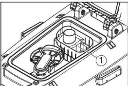
① Coarse dirt filter
②Fluff filter
③ Float
④ Brush head
⑤ Disk brush
⑥Handle
⑦ Safety switch
⑧ Waste water tank drain hose with dosing unit
⑨ Waste water tank lid
⑩Home base retaining rail
⑪ Waste water tank
12** Battery
⑬Fresh water filter
⑭Fresh water tank drain
⑮Brush release pedal
⑯Splash guard
⑰Fresh water tank
⑱Rating plate
⑲Hose clamp
⑳Fresh water tank filling funnel
(21) Suction bar
②2Suction bar closure
②3 Brush head pedal
②4 Suction bar inclination adjustment
⑳Suction hose
②6 Eccentric lever
For fastening the suction bar
27 Fresh water filling level display
28 Water volume regulation knob
29 Battery plug connector
30 Suction bar lever
③1 Key-operated switch
32 Display
③3 Working speed rotary knob (Only for BD 50/55 W Classic Bp)
③4 Driving direction switch (Only for BD 50/55 W Classic Bp)
** Not in scope of delivery
Colour coding
- The control elements for the cleaning process or daily maintenance are yellow.
- The control elements for maintenance and servicing are light grey.
Symbols on the device

Fresh water tank drain opening

Waste water tank drain opening

Fresh water tank filling level (25%)

Insert the charger plug here

Lashing point

* Mop holder

ATTENTION
Incorrect socket
Risk of damage
DO NOT insert the charger plug here
Pedal for raising/lowering the brush head

Brush release pedal

* optional
Installation
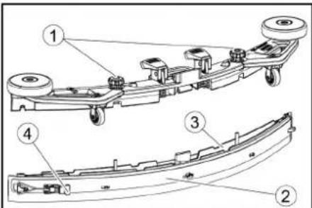
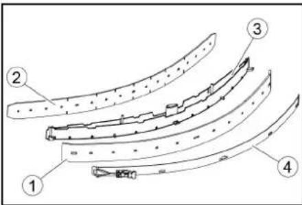
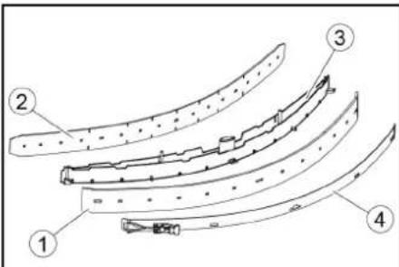
Installing the suction bar
- Pivot both clamping levers upwards.
① Suction hose
② Suction bar suspension
③ Suction bar
④ Clamping lever
-
Insert the suction bar in the suction bar mount.
-
Pivot both clamping levers downwards.
Batteries
Recommended battery sets BD 50/55
| Description Order no. | |
| 115 Ah - Maintenance-free | 2.815-091.0 |
| Description Order no. | |
| 80 Ah - Maintenance-free 2 | 815-090.0 |
| 76 Ah - Maintenance-free 2 | 815-099.0 |
| 105 Ah - Maintenance-free | 2.815-100.0 |
Low-maintenance batteries (wet batteries)
△DANGER
Refilling discharged batteries with water
Danger of acid burns from escaping acid, destruction of clothing
Wear safety goggles when handling the batteries.
Observe the applicable regulations.
Immediately rinse off any splashed acid from the skin or clothing using copious amounts of water.
ATTENTION
Using water with additives
Defective batteries, loss of warranty eligibility
Top up the batteries using only distilled or desalinated water (EN 50272-T3).
Do not use any foreign additives, so-called enhancing agents, because this will invalidate the warranty.
- Add distilled water one hour before the charging process comes to an end. Observe the correct acid level according to the battery label. All cells must produce gas at the end of the charging process.
Maintenance-free batteries (AGM and gel batteries) ATTENTION
Risk of damage when opening AGM and gel batteries!
AGM and gel batteries are maintenance-free and have a closed battery housing. Refilling them with distilled water or battery acid is not possible and is not necessary. Opening or drilling the battery housing will damage an AGM or gel battery. It must then be replaced. Do not open the battery housing and do not drill any holes.
Do not cover the pressure relief valve and do not change it.
- Only charge AGM and gel batteries using the specified chargers, see chapter: Charging the battery.
Installing and connecting batteries
△CAUTION
Removing and installing the batteries
Unstable machine position
Ensure that the machine is positioned stably when removing and installing the batteries.
ATTENTION
Incorrect connection polarity
Destruction of the control electronics
Take care to ensure the correct polarity when connecting the batteries.
ATTENTION
Deep discharge
Risk of damage
Charge the batteries before starting the device.
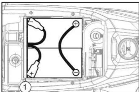
1. Drain the waste water.
2. Lift up the waste water tank, and set it aside.
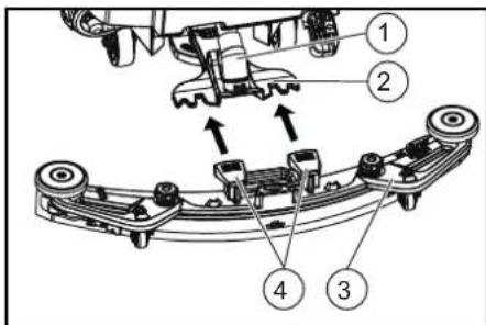
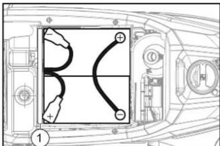
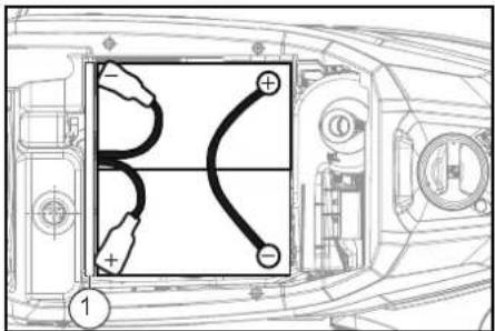
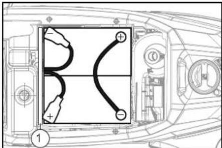
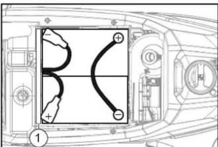
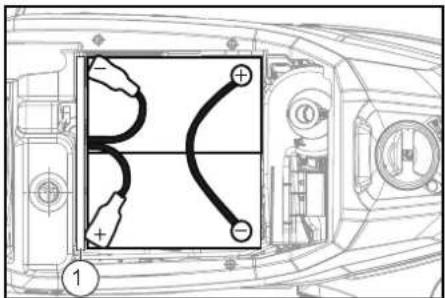
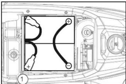
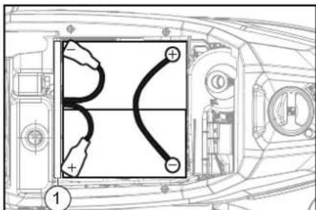
3. Place the battery in the device as shown.
natural_image
Technical line drawing of a vehicle's front view showing internal components and a curved road (no text or symbols)115 Ah, 2.815-091.0
80 Ah, 2.815-090.0
105 Ah, 2.815-100.0

76 Ah, 2.815-099.0
① Spacers
- Connect the poles to the connection cables from the battery installation kit.
- Clamp the connecting cables on the (+) and (-) battery terminals that are still free.
- Connect the device-side battery connector to the battery-side battery connector.
- Recover the waste water tank.
Removing the battery
△CAUTION
Removing and installing the batteries
Unstable machine position
Ensure that the machine is positioned stably when removing and installing the batteries.
- Turn the key-operated switch to "0", and remove the key.
- Disconnect the battery plug.
- Drain the waste water.
- Lift up the waste water tank, and set it aside.
- Disconnect the device-end cable from the negative terminal of the battery.
- Disconnect the remaining cables from the battery.
- Remove the battery.
- Dispose of the used batteries in accordance with statutory provisions.
Initial startup
Charging the battery
△DANGER
Inappropriate use of the charger
Electric shock
Adhere to the mains voltage and fuse values specified on the device type plate.
Only use the charger in dry rooms with sufficient ventilation.
ATTENTION
Accumulation of dangerous gases under the tank during the charging process
Risk of explosion
Pivot the waste water tank upwards before charging low-maintenance batteries.
ATTENTION
Using an unsuitable charger
Risk of damage
Do not connect the charger to the device-side battery connector.
Use only a charger suitable for the type of battery installed.
Read the operating instructions of the charger manufacturer and observe the safety instructions in particular.
| Battery set Capacity | Charger | |
| 2.815-091.0 | 115 Ah | 6.654-329.0 |
| 2.815-090.0 | 80 Ah | 6.654-329.0 |
| 2.815-099.0 | 76 Ah | 6.654-329.0 |
| 2.815-100.0 | 105 Ah | 6.654-329.0 |
The average charging time is approx. 10-15 hours. The device cannot be used during the charging process.
Note
The device has deep discharge protection, i.e. the brush motor and turbine are switched off automatically when the permitted minimum capacity level is reached.
1. Drive the device directly to the charger and do not drive on slopes.
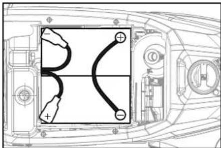
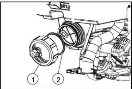
2. Pull out the device-side battery connector.
① Battery connector, device side
②Battery connector, battery side
3. Connect the battery-side battery connector to the charger.
4. Plug the mains plug of the charger into the socket.
5. Carry out the charging process in accordance with the operating instructions for the charger.
- Connect the device-side battery connector to the battery-side battery connector.
Operation
ATTENTION
Risks during operation
Danger of injury
Release the safety switch in the case of danger.
Filling with operating materials
Filling with fresh water
-
Open the fresh water tank cap.
-
Fill fresh water (max. 50 °C) to the lower edge of the filling funnel.
Note
The fresh water hose can be clamped in place using the hose clip while filling.
- Close the fresh water tank cap.
Notes on detergents
△WARNING
Unsuitable detergents
Health risk, damage to the device
Use only recommended detergents. The operator carries all increased risks relating to operational safety and increased risk of accidents if using other detergents. Use only detergents free of solvents, salt and hydrofluoric acid.
Adhere to the safety instructions stated on the detergent packaging.
Note
Do not use heavily foaming detergent.
Recommended detergents
| Usage Detergent | |
| Maintenance cleaning of all water-resistant floors | RM 746RM 756RM 780 |
| Maintenance cleaning of polished hard surfaces (e.g. granite) | RM 755 es |
| Maintenance cleaning and basic cleaning of industrial floors | RM 69 ASF |
| Maintenance cleaning and basic cleaning of fine stone tiles | RM 753 |
| Maintenance cleaning of tiles in sanitary areas | RM 751 |
| Cleaning and disinfection in sanitary areas | RM 732 |
| Coating removal on all alkaline-resistant floors (e.g. PVC) | RM 752 |
| Coating removal on linoleum floors | RM 754 |
Detergent
- Fill the detergent into the fresh water tank.
Note
The cap for the fresh water tank filling funnel can be used for measuring the correct quantity of detergent. It has a measuring scale marked on the inner side.
Adjusting the water volume
- Adjust the water volume via the regulating knob to suit the degree of soiling of the floor covering.
Note
Perform initial cleaning tests with a low water volume. Increase the water volume step by step until achieving the desired cleaning result.
Note
The brush head continues operating without a liquid supply if the fresh water tank is empty.
Adjusting the suction bar
Adjusting the inclination
The inclination must be adjusted so that the suction lips of the suction bar make even contact with the floor over the entire length of the suction bar.
- Park the device on a surface without a slope
- Turn the key-operated switch to "ON". Put down the suction bar.
- Drive the device a small distance forwards.
- Read the spirit level.
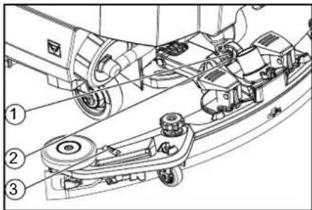
1 Screw
2 Nut
③ Spirit level
- Unscrew the nut.
- Adjust the screw so that the spirit level indicator is between the two lines.
- Tighten the nut.
- To check the new setting, move the device forward again a short distance. Repeat the adjustment process if necessary.
- Turn the key-operated switch to "OFF".
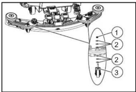
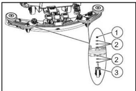
Adjusting the height
The height adjustment affects the bending of the suction lips on contact with the floor.
Note
Standard setting: 3 washers above, 3 washers below the suction bar.
Uneven floor: 5 washers above, 1 washer below the suction bar.
Very smooth floor: 1 washer above, 5 washers below the suction bar.
- Unscrew the nuts.

①Nut
② Washer
③ Spacer roller with holder
- Place the desired number of washers between the suction bar and the spacer roller.
- Fit the remaining unused washers above the spacer roller.
- Screw on the nut and tighten.
- Repeat the entire procedure with the second spacer roller.
Note
Set both spacer rollers to the same height.
Cleaning
Switching on the device
- Turn the key-operated switch to "1".
The display shows the following one after the other: - Kärcher
- Charging state of the battery and number of operating hours
- Period of time until the next after-sales servicing for the customer
- Software version, control panel
- Charging state of the battery and number of operating hours (for BD 50/55 C Classic Bp) Charging state of the battery and speed (for BD 50/55 W Classic Bp)
Driving
Note
The direction of travel can be changed during the cleaning operation. This way, a certain position can be intensively cleaned by driving back and forth several times.
- Set the driving direction switch to "forward".
Cleaning
Note
The inclination and height of the suction bar can be adjusted to improve the vacuuming results (see chapter Adjusting the suction bar).
Note
When the waste water tank is full, the float switch closes the suction opening and the suction turbine runs at a higher speed. In this case, raise the suction bar and drive to the location for emptying the waste water tank.
-
Turn the working speed rotary knob to the desired value. The speed is shown on the display during the adjustment. The display is shown in percentage of the maximum speed.
-
Set the water volume at the regulating valve.
- Press the suction bar lever downwards.
The suction bar lowers.
Vacuuming begins.
- Press the brush head pedal downwards, unlatch it and allow it to move upwards.
- Pull the safety switch towards the push handle. The brush head starts up and the device moves at the set speed.
Finishing operation
Finishing cleaning
- Let go of the safety switch
- Press the brush head pedal down and latch it in place.
- Continue moving a short distance.
The residual water is vacuumed up.
- Lift the suction bar.
The suction continues to run for 10 seconds.
5. Turn the key-operated switch to "0".
6. Charge the battery if necessary.
Draining the waste water
△WARNING
Improper disposal of waste water
Environmental pollution
Observe the local waste water treatment regulations.
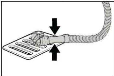
- Remove the drain hose from the support and lower it over a suitable collecting device.
natural_image
Diagram of a hand holding a flexible hose with directional arrows indicating movement or force (no text or symbols)- Press the dosing unit together or kink the hose.
- Open the dosing unit cover.
- Drain the waste water. Regulate the water volume by pressing or kinking.
- Rinse the waste water tank with clear water.
Quickly draining fresh water
- Unscrew the fresh water drain cap.
- Allow the fresh water to drain away.
- Fit the fresh water drain cap and screw into place.
Note
Take care to ensure that the hose connection in the fresh water tank cap is positioned at the lowest point in the tank after screwing the cap in place.
Transport
△DANGER
Driving on slopes
Risk of injury
Observe the maximum permissible inclination when driving the device on slopes for loading and unloading purposes (see Chapter Technical data).
Drive slowly.
△CAUTION
Failure to observe the weight
Risk of injury and damage
Be aware of the weight of the device during transport. Only load the device with the assistance of another person or by using the drive.
- Press the brush head pedal down, and latch it in place.
- Raise the suction bar.
- Turn the key-operated switch to "1"
- Select the travel direction with the travel direction switch.
-
Pull the safety switch towards the push handle.
-
When transporting in vehicles, secure the device against slipping and tipping over according to the applicable guidelines.
Storage
△CAUTION
Failure to observe the weight
Risk of injury and damage
Be aware of the weight of the device during storage.
ATTENTION
Frost
Destruction of the device through freezing water Drain all water from the device.
Store the device in a frost-free location.
• This device may only be stored indoors.
- Fully charge the batteries before storing them for a long period.
- Fully charge the batteries at least every month during storage.
Care and service
△DANGER
Inadvertently starting up device
Risk of injury, electric shock
Turn the key-operated switch to "0" and remove the key before performing any work on the device.
Pull out the charger mains plug.
- Drain and dispose of the waste water and fresh water.
Safety inspection/maintenance contract
You can agree on regular safety inspections or close a maintenance contract with your dealer. Please seek advice on this.
Maintenance intervals
Each time after use
ATTENTION
Improper cleaning
Risk of damage.
Do not spray the device with water.
Do not use aggressive cleaning agents.
A detailed description of the individual maintenance
work is provided in Chapter Maintenance work.
- Drain the waste water.
● Rinse the waste water tank with clear water. - Clean the exterior of the device using a damp cloth, wetted with a mild washing lye.
- Check the fluff filter and clean if required.
- Clean the coarse dirt filter.
- Clean the suction lips, check for wear and adjust the height or replace if necessary.
- Check the disc brushes for wear and replace if necessary.
- Charge the battery.
- If the charging state of the battery is below 50%, charge the battery fully and without interruption.
- If the charging state of the battery is above 50%, only recharge the battery if the entire operating duration will be required when next used.
Weekly
- When used regularly, charge the battery fully and without interruption at least once a week.
Monthly
A detailed description of the individual maintenance work is provided in Chapter Maintenance work.
- Drain the fresh water tank and flush out deposits.
- Clean the fresh water filter.
- Clean the float and fluff filter.
- Check battery poles for oxidation, brush off if necessary. Make sure the connection cables are firmly in place.
- Clean the seals between the waste water tank and the cover, check for leaks and replace if necessary.
-
Check the acid density of the cells if the batteries are not maintenance-free.
-
For longer periods of disuse, shut down the device when the battery is fully charged. Fully charge the battery at least once a month.
Annually
● Have the prescribed inspection performed by Customer Service.
Maintenance work
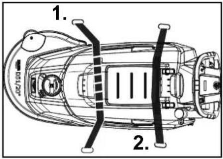
Turn over or replace the worn suction lips
The suction lips must be turned over or replaced when worn out.
- Remove the suction bar.
- Unscrew the star handles.
①Star grip
②Strap
③Inner part of the suction bar
④ Tension lock
3. Pull out the inner part of the suction bar.
4. Open the tension lock.
5. Remove the strap.
6. Release the suction lips from the inner part.

①Rear suction lip
②Front support lip
③Inner part of the suction bar
4 Strap
-
Press the turned or new suction lips onto the knobs of the inner part of the suction bar.
-
Attach the strap.
- Push the inner part of the suction bar into the upper part.
- Screw in and tighten the star handles.
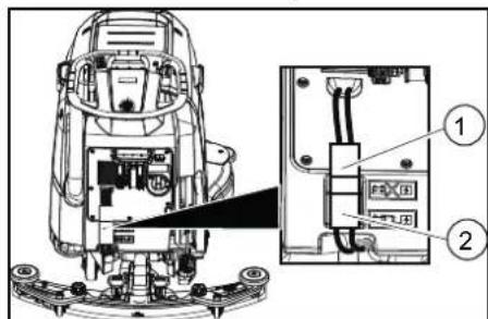
Cleaning the coarse dirt filter
- Open the waste water tank cover.
natural_image
Technical line drawing of a mechanical assembly with internal components (no text or symbols)①Coarse dirt filter
- Pull the coarse dirt filter upwards and off.
- Rinse off the coarse dirt filter under running water.
- Reinsert the coarse dirt filter into the waste water tank.
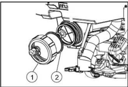
Cleaning the fresh water filter
- Drain the fresh water (see Chapter Quickly draining fresh water).
- Unscrew the fresh water tank cap.
① Fresh water tank cap
② Fresh water filter
3. Pull out the fresh water filter and rinse with clean water.
4. Insert the fresh water filter.
5. Fit the fresh water tank cap
Note: Take care to ensure that the hose connection in the fresh water tank cap is positioned at the lowest point in the tank after screwing the cap in place.
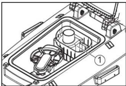
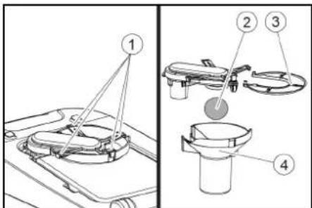
Clean the float and fluff filter
- Open the waste water tank cover.
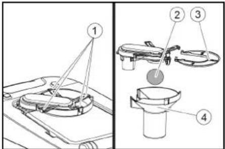
① Latching hooks
②Float
③Fluff filter
④Float housing
- Release the latching hooks.
- Pull the float housing downwards and off.
- Remove the float from the float housing and clean it.
- Remove the fluff filter and clean it.
- Assemble all parts in the reverse order.
Replacing the disc brush
Note
Replace the disc brushes when the bristle length has reached 10 mm.
- Raise the brush head.
- Push the brush release pedal down.
- Pull the disc brush sideways and out from underneath the brush head.
- Hold the new disc brush under the cleaning head, then press upwards and latch it into position.
Troubleshooting guide
| △DANGERInadvertently starting up deviceRisk of injury, electric shockTurn the key-operated switch to "0" and remove the key before performing any work on the device. | Pull out the charger mains plug.Drain and dispose of the waste water and fresh water.Contact Customer Service in the case of malfunctions that cannot be corrected using this table. | △WARNINGBe careful when approaching blind corners, bushes, trees or objects that might restrict your view. | |
| Malfunction Rectification | |||
| The device cannot be started 1. Turn the key-operated switch to "1".2. Actuate the safety switch.3. Insert the battery plug.4. Check the battery and charge if necessary.5. Check that the battery terminals are correctly connected. | |||
| The water volume is insufficient | 1. Check the fresh water filling level and fill the tank if necessary.2. Increase the water volume at the water volume regulating knob.3. Clean the fresh water filter.4. Check the hoses for clogging and clean if necessary. | ||
| The suction performance is too low 1. | Shut down the device and drain the waste water.2. Clean the seals between the waste water tank and the cover, check for leaks and replace if necessary.3. Check that the suction hose is correctly connected to the waste water tank.4. Check the fluff filter for soiling and clean if necessary.5. Clean the suction lips at the suction bar, turn over or replace if necessary.6. Check that the cap on the waste water drain hose is closed.7. Check the adjustment of the suction bar.8. Check the suction hose for clogging and clean if necessary.9. Check the suction hose for leaks and replace if necessary. | ||
| The cleaning results are unsatisfactory | 1. Reduce the driving speed.2. Check the brushes for wear and replace if necessary.3. Check the suitability of the brush type and detergent used. | ||
| The suction turbine runs at an increased speed | 1. Drain the waste water.2. Clean the float.3. Check the fluff filter and clean if necessary.4. Check the suction hose for clogging and clean if necessary.5. Check the suction bar for clogging and remove any clogging if necessary | ||
| The brushes do not rotate | 1. Check if the brushes are blocked by a foreign body and remove the foreign body if necessary. | ||
| The device vibrates during cleaning 1. | Use a softer brush. | ||
Warranty
| The warranty conditions issued by our relevant sales company apply in all countries. We shall remedy possible malfunctions on your appliance within the warranty | period free of cost, provided that a material or manufacturing defect is the cause. In a warranty case, please | contact your dealer (with the purchase receipt) or the next authorised customer service site.(See overleaf for the address) |
Accessories
| Description Part no. Description | ||
| Disc brush, complete red D51 9.753-021.0 | For general cleaning, for all surfaces. | |
| Disc brush, (very soft) | 4.905-028.0 | For cleaning sensitive floors and polishing. |
| Disc brush, (soft) | 4.905-027.0 | Made of natural fibers, for cleaning and polishing. |
| Disc brush, (medium soft) | 4.905-026.0 | For general cleaning, for all surfaces. |
| Disc brush, (hard) | 4.905-029.0 | For stubborn dirt and deep cleaning. Only for hard-wearing surfaces. |
| Pad drive board, 479 mm | 4.762-534.0 | For cleaning with pads. With quick-change coupling and Centerlock. |
| Pad, 500 mm, (soft) | 6.371-146.0 | With natural hair, for polishing. Removes scuff marks effectively. |
| Pad, 508 mm, (soft) | 6.369-468.0 | Light grit, suitable for polishing floors. |
| Pad, 508 mm, (medium-soft) | 6.369-079.0 | For cleaning all types of floors. |
| Pad, 508 mm, (medium-hard) | 6.369-078.0 | For removing stubborn dirt and deep cleaning. |
| Pad, 508 mm, (hard) | 6.369-077.0 | For cleaning heavily soiled floors and for deep cleaning. |
| Diamond pad, 508 mm, (coarse) | 6.371-260.0 | For coarse cleaning / restoring. Removes small scratches, for a clean, silky matt surface. For surface preparation prior to using the yellow pad. As a crystallization pad for basic crystallization. |
| Diamond pad, 508 mm, (medium) | 6.371-261.0 | For coarse cleaning / restoring. Removes fine scratches for a more homogenous and shinier surface. For surface preparation prior to using the green diamond pad. As a crystallization pad for high-gloss crystallization. |
| Diamond pad, 508 mm, (fine) | 6.371-240.0 | For effortless polishing of laminated floors, terrazzo, and natural stone surfaces. For maintenance cleaning after using white and yellow pads. |
| Microfiber pad, 508 mm | 6.371-271.0 | Excellent cleaning power. Also effectively cleans fine stoneware tiles. |
| Melamine pad, 508mm | 6.371-025.0 | Melamine pad set for the effective cleaning of microporous surfaces. |
| Squeegee, 850mm | 4.778-008.0 | Parabolic squeegee, Suction lips made of wear-resistant, red Linatex, with support rollers. |
| Suction lips, 33in, red | 4.400-011.0 | Made from Linatex, wear-resistant. |
| Suction lips, 33in, transparent 4.400-005.0 | Made from PU, oil-resistant. | |
Technical data
| BD 50/55 W Classic Bp | BD 50/55 C Classic Bp | ||
| Device performance data | |||
| Nominal voltage | V | 24 | 24 |
| Battery capacity | Ah (5 h) | 80 / 115 | 80 / 115 |
| Mean power input | W | 880 | 750 |
| Driving motor power | W | 130 | - |
| Suction turbine power | W | 250 | 250 |
| Brush drive power | W | 500 | 500 |
| Theoretical surface performance | m^2/h | 2550 | 2040 |
| Fresh water tank capacity | I | 55 | 55 |
| Waste water tank capacity | I | 55 | 55 |
| BD 50/55 W Classic Bp | BD 50/55 C Classic Bp | |||
| Water temperature max. °C 50 50 | ||||
| Water pressure max. bar 0.06 0.06 | ||||
| Max. working area slope % 2 2 | ||||
| Vacuuming | ||||
| Suction performance, air quantity l/s 24 24 | ||||
| Suction performance, vacuum kPa (mbar) | 9.5 (95) | 9.5 (95) | ||
| Cleaning brushes | ||||
| Working width | mm | 510 | 510 | |
| Brush diameter | mm | 510 | 510 | |
| Brush speed | 1/min | 140 | 140 | |
| Brush contact pressure | kg | ≥ 27 | ≥ 27 | |
| Dimensions and weights | ||||
| Approved total weight | kg | 240 | 225 | |
| Net weight (transport weight) | kg | 115 | 110 | |
| Battery compartment dimensions | mm | 330 x 355 x 290 | 330 x 355 x 290 | |
| Determined values in acc. with EN 60335-2-72 | ||||
| Overall vibration value | m/s^2 | <2.5 <2.5 | ||
| Uncertainty K dB(A) | 0.2 | 0.2 | ||
| Sound pressure level L_pA | dB(A) | 65.2 65.2 | ||
| Uncertainty K_pA | dB(A) | 2 2 | ||
| Sound power level L_WA + K uncertainty_WA | dB(A) | 84.1 84.1 | ||
Subject to technical modifications.
EU Declaration of Conformity
We hereby declare that the machine described below complies with the relevant basic safety and health requirements in the EU Directives, both in its basic design and construction as well as in the version placed in circulation by us. This declaration is invalidated by any changes made to the machine that are not approved by us.
Product: Floor cleaner
Type: 1.127-xxx
Currently applicable EU Directives
2006/42/EC (+2009/127/EC)
2014/30/EU
2014/53/EU (TCU)
Harmonised standards used
EN 60335-1
EN 60335-2-72
EN 60335-2-29
EN 62233: 2008
EN 55012: 2007 + A1: 2009
EN 61000-6-2: 2005
TCU
EN 300 328 V2.1.1
EN 300 330 V2.1.1
EN 300 440 V2.1.1
EN 301 511 V12.5.1
EN 62368-1:2014+A11:2017
National standards used
The undersigned act on behalf and under the power of attorney of the company management.

Chairman of the Board of Management

S. Reiser
Director Regulatory Affairs & Certification
Documentation supervisor:
S. Reiser
Alfred Kärcher SE & Co. KG
Alfred-Kärcher-Str. 28 - 40
71364 Winnenden (Germany)
Ph.: +49 7195 14-0
Fax: +49 7195 14-2212
Winnenden, 2019/01/25
Contenu
natural_image
Technical line drawing of a vehicle interior with no visible text or symbols115 Ah, 2.815-091.0
80 Ah, 2.815-090.0
105 Ah, 2.815-100.0

76 Ah, 2.815-099.0
① Entretoises
①Vis
②Écrou
③ Niveau à bulle
①Écrou
②Rondelle
natural_image
Diagram showing a hand connecting a plastic tray with a coiled hose, indicating fluid or electrical connection (no text or symbols present)① Poignée-étoile
② Bande de serrage
natural_image
Technical line drawing of a mechanical assembly with no visible text or symbols2006/42/CE (+2009/127/CE)
2014/30/UE
2014/53/EU (TCU)

H. Jenner
Chairman of the Board of Management

S. Reiser
Director Regulatory Affairs & Certification
71364 Winnenden (Germany)
Tél. : +49 7195 14-
Winnenden, 2019/01/25
Indice
natural_image
Technical line drawing of a vehicle's front view showing internal components and wiring (no text or symbols)115 Ah, 2.815-091.0
80 Ah, 2.815-090.0
105 Ah, 2.815-100.0

76 Ah, 2.815-099.0
① Distanziatore
①Dado
②Rondella
natural_image
Diagram showing a hand connecting a flexible hose to a device with directional arrows indicating movement (no text or symbols)natural_image
Technical line drawing of a mechanical assembly with no visible text or symbols
H. Jenner
Chairman of the Board of Management

S. Reiser
Director Regulatory Affairs & Certification
71364 Winnenden (Germany)
Tel.: +49 7195 14-0
Fax: +49 7195 14-2212
Winnenden, 25/01/2019
Inhoud
Aftapopening verswaterreservoir

Aftapopening vuilwaterreservoir

Vulstand verswaterreservoir (25%)

① Zuigslang
② Zuigbalkophanging
③Zuigbalk
④Klemhendel
natural_image
Technical line drawing of a vehicle interior with no visible text or symbols115 Ah, 2.815-091.0
80 Ah, 2.815-090.0
105 Ah, 2.815-100.0

76 Ah, 2.815-099.0
1 Afstandsstuk
① Schroef
② Moer
③Waterpas
natural_image
Diagram of a hand holding a flexible hose with directional arrows indicating movement or force (no text or symbols)① Achterste zuiglip
②Voorste steunlip
natural_image
Technical line drawing of a mechanical assembly with no visible text or symbols① Grofvuilzeef
① Grendelhaak
②Vlotter
③ Pluizenzeef
④ Vlotterbehuizing

H. Jenner
Chairman of the Board of Management

S. Reiser
Director Regulatory Affairs & Certification
71364 Winnenden (Germany)
Tel.: +49 7195 14-0
Fax: +49 7195 14-2212
Winnenden, 2019/01/25
natural_image
Technical line drawing of a vehicle interior with no visible text or symbols115 Ah, 2.815-091.0
80 Ah, 2.815-090.0
105 Ah, 2.815-100.0

76 Ah, 2.815-099.0
① Distanciador
natural_image
Diagram of a hand holding a flexible hose with directional arrows indicating movement or force (no text or symbols)natural_image
Technical line drawing of a mechanical assembly with no visible text or symbols2006/42/CE (+2009/127/CE)
2014/30/UE
2014/53/UE (TCU)
Chairman of the Board of Management

S. Reiser
Director Regulatory Affairs & Certification
71364 Winnenden (Germany)
Tel.: +49 7195 14-0
Fax: +49 7195 14-2212
Winnenden, 25/01/2019
Índice
natural_image
Technical line drawing of a vehicle's front view showing internal components and wiring (no text or symbols)115 Ah, 2.815-091.0
80 Ah, 2.815-090.0
105 Ah, 2.815-100.0

76 Ah, 2.815-099.0
①Espaçador
①Parafuso
②Porca
③ Nível de bolha
①Porca
②Anilha
natural_image
Diagram of a hand holding a flexible hose with directional arrows indicating movement or force (no text or symbols)natural_image
Technical line drawing of a mechanical assembly with no visible text or symbols2006/42/CE (+2009/127/CE)
2014/30/UE
2014/53/UE (TCU)
Chairman of the Board of Management

S. Reiser
Director Regulatory Affairs & Certification
Winnenden, 25/01/2019
Indhold
115 Ah, 2.815-091.0
80 Ah, 2.815-090.0
105 Ah, 2.815-100.0

76 Ah, 2.815-099.0
① Afstandsholder
① Batteristik, maskinside
Faresituation under driften
① Skrue
②Møtrik
③ Vaterpas
natural_image
Diagram of a hand holding a flexible hose connected to a rectangular device with ventilation slots (no text or symbols)①Stjernegreb
② Spændebänd
natural_image
Technical line drawing of a mechanical assembly with no visible text or symbols① Grovsi
2006/42/EF (+2009/127/EF)
2014/30/EU
2014/53/EU (TCU)

H. Jenner
Chairman of the Board of Management

S. Reiser
Director Regulatory Affairs & Certification
71364 Winnenden (Germany)
Tlf.: +49 7195 14-0
Fax: +49 7195 14-2212
Winnenden, 2019/01/25
Indhold
Generelle merknader 59
Funksjon 59
Forskriftsmessig bruk.... 59
Miljøvern 59
① Grovsmussil
②Losil
③ Flottør
④Børstehode
⑤ Skivebørste
⑥Hándtak
⑦ Sikkerhetsbryter
⑧ Tappeslange for smussvann med doseringsinnretning
① Sugeslange
② Sugebomoppheng
③ Sugebom
④Lasearm
- Sett sugebommen inn i sugebomopphenget.
- Skyv begge klemspakene ned.
Batterier
Anbefalte batteripakker BD 50/55
| Beskrivelse Ordrenr. | |
| 115 Ah – vedlikeholdsfri 2.8 | 15-091.0 |
| 80 Ah – vedlikeholdsfri 2.8 | 5-090.0 |
| 76 Ah – vedlikeholdsfri 2.8 | 5-099.0 |
| 105 Ah – vedlikeholdsfri 2.8 | 15-100.0 |
Lite vedlikeholdskrevende batterier (våtbatterier)
△FARE
natural_image
Technical line drawing of a vehicle's front view showing internal components and a highlighted section (no text or symbols)115 Ah, 2.815-091.0
80 Ah, 2.815-090.0
105 Ah, 2.815-100.0
76 Ah, 2.815-099.0
① Avstandsholder
①Batteriplugg, maskinside
②Batteriplugg, batteriside
① Skrue
②Mutter
③ Vater
①Mutter
②Underlagsskive
③Avstandshjul med holder
2. Legg ønsket antall underlagsskiver mellom sugebommen og avstandshjulet.
3. Plasser resten av underlagsskivene over avstandshjulet.
4. Skru på mutrene og stram dem.
5. Gjenta fremgangsmåten med det andre avstandshjulet.
Merknad
natural_image
Diagram of a hand holding a flexible hose with directional arrows indicating movement or force (no text or symbols)①Stjernehåndtak
2 Strammebånd
③Innvendig del sugebom
④ Strammelås
①Bakre sugeblad
②Fremre støtteblad
③Innvendig del sugebom
④Strammebänd
- Trykk de vendte eller nye sugebladene på knottene på den innvendige delen av sugebommen.
- Monter strammebändet.
- Skyv den innvendige delen av sugebommen inn i overdelen.
- Skru inn stjernegrepene og stram dem.
Rengjøre grovsmussilen
natural_image
Technical line drawing of a mechanical assembly with no visible text or symbols① Grovsmussil
①Lokk rentvannstank
②Ferskvannsfilter
2006/42/EF (+2009/127/EF)
2014/30/EU
2014/53/EU (TCU)
Anvendte harmoniserte standarder
EN 60335
EN 60335-2-72
EN 60335-2-29
EN 62233: 2008
EN 55012: 2007 + A1: 2009
EN 61000-6-2: 2005
TCU
EN 300 328 V2.1.1
EN 300 330 V2.1.1
EN 300 440 V2.1.1
EN 301 511 V12.5.1
EN 62368-1:2014+A11:2017
H. Jenner
Board of Management
S. Reiser
Director Regulatory Affairs & Certification
71364 Winnenden (Germany)
Tlf.: +49 7195 14-0
Winnenden, 25/01/2019
Innehåll
Allmän information 66
Funktion 66
① Sugslang
② Sugbalksfäste
③ Sugbalk
④ Klämspak
natural_image
Technical line drawing of a vehicle interior with no visible text or symbols115 Ah, 2.815-091.0
80 Ah, 2.815-090.0
105 Ah, 2.815-100.0

76 Ah, 2.815-099.0
① Distanshållare
natural_image
Diagram showing a hand connecting a plastic sheet with a coiled hose, indicating fluid or electrical connection (no text or symbols present)natural_image
Technical line drawing of a mechanical assembly with no visible text or symbols① Grovsmutssil
① Spärrhake
②Flottör
③Luddsil
④ Flottörkapsling

Jenner
Chairman of the Board of Management

S. Reiser
Director Regulatory Affairs & Certification
D-71364 Winnenden (Germany)
Tfn: +49 7195 14-0
Fax: +49 7195 14-2212
Winnenden, 2019/01/25
Sisältö
natural_image
Technical line drawing of a vehicle's front view showing internal components and a curved path (no text or symbols)115 Ah, 2.815-091.0
80 Ah, 2.815-090.0
105 Ah, 2.815-100.0
76 Ah, 2.815-099.0
①Välikappale
natural_image
Diagram of a flexible hose connecting a tray with a handle, showing directional arrows (no text or symbols)natural_image
Technical line drawing of a mechanical assembly with no visible text or symbols①Karkean lian seula
natural_image
Technical line drawing of a mechanical component with labeled connection point (no text or symbols beyond the number 1)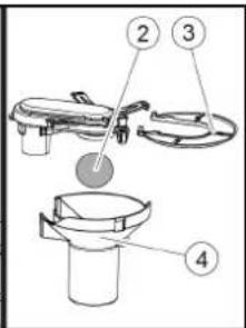
① Lukitushaat
②Uimuri
③ Nukkasihti
④Uimurikotelo

H. Jenner
Chairman of the Board of Management

S. Reiser
Director Regulatory Affairs & Certification
Dokumentointivastaava: S. Reiser
Alfred Kärcher SE & Co. KG
Alfred-Kärcher-Str. 28 - 40
71364 Winnenden (Germany)
Puh.: +49 7195 14-0
115 Ah, 2.815-091.0
80 Ah, 2.815-090.0
105 Ah, 2.815-100.0

76 Ah, 2.815-099.0
①Αποστάτης
①Bíðα
② Παξιμάδι
③ Αλφάδι
① Παξιμάδι
②Ροδέλα
natural_image
Diagram showing a hand holding a flexible hose with directional arrows indicating movement or force (no text or symbols present)natural_image
Technical line drawing of a mechanical assembly with no visible text or symbols①Άγκιστρα ασφάλισης
②Φλοτέρ
③ Φίλτρο χνουδιών
④ Περίβλημα φλοτέρ
Chairman of the Board of Management

S. Reiser
Director Regulatory Affairs & Certification
71364 Winnenden (Germany)
Tηλ.: +49 7195 14-0
Φαξ: +49 7195 14-2212
Winnenden, 2019/01/25
İçindekiler
Genel uyarılar 87
Fonksiyon....87
①Vakum hortumu
natural_image
Technical line drawing of a vehicle battery pack with no visible text or symbols115 Ah, 2.815-091.0
80 Ah, 2.815-090.0
105 Ah. 2.815-100.0

76 Ah, 2.815-099.0
① Ara parça
1 Somun
②Pul
③Tutuculu mesafe tekeri
natural_image
Diagram of a medical device with a coiled tube and directional arrows indicating movement or force (no text or symbols)① Yıldız kol
②Germe bandi
①Arka emme dudağı
②Ön emme dudağı
natural_image
Technical line drawing of a mechanical assembly with no visible text or symbols①ri kir süzgeci
2006/42/AT (+2009/127/AT)
2014/30/AB
2014/53/EU (TCU)

H. Jenner
Chairman of the Board of Management

S. Reiser
Director Regulatory Affairs & Certification
Winnenden, 2019/01/25
Содержание
Общие указания 94
① Всасывающий шланг
115 A·4, 2.815-091.0
80 A·4, 2.815-090.0
105 A·4, 2.815-100.0
76 A·4, 2.815-099.0
① Проставка
①ВИНТ
②Гайка
③Уровень
①Гайка
②Подкладочная шайба
natural_image
Diagram showing a flexible hose connecting a device with a valve, indicating fluid flow or electrical connection (no text or symbols present)natural_image
Technical line drawing of a mechanical assembly with no visible text or symbols①Фиксирующие крюки
②Поплавок
③Ворсовый фильтр
④Корпус поплавка

H. Jenner
Chairman of the Board of Management

S. Reiser
Director Regulatory Affairs & Certification
71364 Winnenden (Germany)
Тел.: +49 7195 14-0
Факс: +49 7195 14-2212
① Szívótömlő
115 Ah, 2.815-091.0
80 Ah, 2.815-090.0
105 Ah, 2.815-100.0
76 Ah, 2.815-099.0
①Távtartó
①Csavar
② Anya
③ Vízmérték
① Anya
② Alátét
natural_image
Diagram of a flexible hose connecting a plastic tray with a coiled hose, showing directional arrows (no text or symbols)natural_image
Technical line drawing of a mechanical device interior with labeled component (1), no readable text or symbols present.① Durva szennyszürő

H. Jenner
Chairman of the Board of Management

S. Reiser
Director Regulatory Affairs & Certification
① Sací hadice
natural_image
Technical line drawing of a vehicle's front view showing internal components and wiring (no text or symbols)115 Ah, 2.815-091.0
80 Ah, 2.815-090.0
105 Ah, 2.815-100.0
76 Ah, 2.815-099.0
① Rozpěrka
①Šroub
② Matice
③Vodováha
① Matice
② Podložka
natural_image
Diagram of a flexible hose connecting a flat panel with a handle, showing directional arrows (no text or symbols)natural_image
Technical line drawing of a mechanical assembly with no visible text or symbols①Síto na hrubé nečistoty
2006/42/ES (+2009/127/ES)
2014/30/EU
2014/53/EU (TCU)

H. Jenner
Chairman of the Board of Management

S. Reiser
Director Regulatory Affairs & Certification
Winnenden, 2019/01/25
Kazalo
Splošna navodila.... 115
Delovanje 115
Namenska uporaba.... 115
Varovanje okolja.... 115
Pribor in nadomestni deli 115
Obseg dobave.... 115
Varnostna navodila 115
Opis naprave.... 116
Montaža 117
Zagon....117
Obratovanje 118
Transport.... 118
www.kaercher.com/REACH
Pribor in nadomestni deli
Uporabljajte samo originalni pribor in originalne nado- mestne dele, ki zagotavljajo varno in nemoteno delova- nje naprave.
Informacije o priboru in nadomestnih delih najdete na spletnem naslovu www.kaercher.com.
Obseg dobave
① Sito za grobo umazanijo
② Sito za kosme
③Plovec
④Glava krtače
⑤Kolutna krtača
⑥Ročaj
⑦Varnostno stikalo
⑧Gibka izpustna cev za umazano vodo z dozirno na-pravo
⑨Pokrov rezervoarja za umazano vodo
⑩Držalna tirnica Home Base
⑪Rezervoar za umazano vodo
12**Baterija
⑬Filter za svežo vodo
⑭Izpust rezervoarja za svežo vodo
⑮Pedal za sprostitev krtače
⑯Zaščita pred brizgi
⑰Rezervoar za svežo vodo
① Sesalna gibka cev
② Obesa sesalnega prečnika
③ Sesalni prečnik
④Prižemna ročica
natural_image
Technical line drawing of a vehicle's front view showing internal components and wiring (no text or symbols)115 Ah, 2.815-091.0
80 Ah. 2.815-090.0
105 Ah, 2.815-100.0

76 Ah, 2.815-099.0
① Distančniki
① Vtič baterije, na strani naprave
① Vijak
② Matica
③Vodna tehtnica
①Matica
② Podložka
natural_image
Diagram of a medical device with a coiled tube and directional arrows indicating fluid flow (no text or symbols)- Stisnite ali prepognite dozirno napravo.
- Odprite pokrov dozirne naprave.
- Izpustite umazano vodo. Količino vode regulirajte s stiskanjem ali prepogibanjem.
- Rezervoar za umazano vodo sperite s čisto vodo.
①Zvezdasti ročaj
②Napenjalni trak
③ Notranji del sesalnega prečnika
④ Natezalno zapiralo
3. Izvlecite notranji del sesalnega prečnika.
4. Odprite natezalno zapiralo.
5. Odstranite napenjalni trak.
6. Sesalne nastavke vzemite iz notranjega dela.
natural_image
Technical line drawing of a mechanical assembly with no visible text or symbols① Sito za grobo umazanijo
2. Sito za grobo umazanijo odstranite v smeri navzgor.
3. Sperite sito za grobo umazanijo pod tekočo vodo.
- Vstavite sito za grobo umazanijo v rezervoar za umazano vodo.
①Zapiralo rezervoarja za svežo vodo
②Filter za svežo vodo
2006/42/ES (+2009/127/ES)
2014/30/EU
2014/53/EU (TCU)

H. Jenner
Chairman of the Board of Management

S. Reiser
Director Regulatory Affairs & Certification
① Wąż ssący
natural_image
Technical line drawing of a vehicle interior with no visible text or symbols115 Ah, 2.815-091.0
80 Ah, 2,815-090.0
105 Ah, 2,815-100.0
76 Ah, 2,815-099.0
①Przekładki
① Nakrętka
②Podkładka
natural_image
Diagram of a hand holding a flexible hose connected to a device with arrows indicating direction (no text or symbols)①Tylna warga ssąca
natural_image
Technical line drawing of a mechanical assembly with no visible text or symbols2006/42/WE (+2009/127/WE)
2014/30/UE
2014/53/EU (TCU)

H. Jenner
Chairman of the Board of Management

S. Reiser
Director Regulatory Affairs & Certification
71364 Winnenden (Germany)
Tel.: +49 7195 14-0
natural_image
Technical line drawing of a vehicle front view with internal components and no visible text or symbols115 Ah, 2.815-091.0
80 Ah, 2.815-090.0
105 Ah, 2.815-100.0

76 Ah, 2.815-099.0
① Distantier
①Surub
② Piuliţă
③Cântar de apă
① Piuliţă
② Saiba plată
natural_image
Diagram showing a hand holding a flexible hose with arrows indicating force or movement (no text or symbols)natural_image
Technical line drawing of a mechanical device interior with no visible text or symbolsDirective UE relevante
2006/42/UE (+2009/127/UE)
2014/30/UE
2014/53/UE (TCU)
Norme armonizate aplicate
EN 60335-1
EN 60335-2-72
EN 60335-2-29
EN 62233: 2008
EN 55012: 2007 + A1: 2009
EN 61000-6-2: 2005
TCU
EN 300 328 V2.1.1
EN 300 330 V2.1.1
EN 300 440 V2.1.1
EN 301 511 V12.5.1
EN 62368-1:2014+A11:2017

H. Jenner
Chairman of the Board of Management

S. Reiser
Director Regulatory Affairs & Certification
71364 Winnenden (Germania)
Tel.: +49 7195 14-0
Fax: +49 7195 14-2212
Winnenden, 2019/01/25
Obsah
Všeobecné upozornenia 136
Funkcia 136
① Filter na hrubé nečistoty
②Filter na žmolky
③ Plavák
④Kefová hlava
⑤ Kotúčová kefa
⑥Rukovät'
① Sacia hadica
②Upevnenie sacej lišty
③ Sacia lišta
④Upínacia páka
2. Saciu listu vložte do upevnenia sacej lišty.
3. Otočte obe upínacie páky smerom nadol.
natural_image
Technical line drawing of a vehicle interior with no visible text or symbols115 Ah, 2.815-091.0
80 Ah, 2.815-090.0
105 Ah, 2.815-100.0
76 Ah, 2.815-099.0
① Rozpierka
- Póly spojte so spojovacími káblami z inštalačnej súpravy batérie.
- Pripojovacie kable upnite na este vořné pólty batérie (+) a (-).
- Zástrčku batérie na strane prístroja spojte so zástrčkou batérie na strane batérie.
- Nádrž na znečistenú vodu vyklopte smerom nadol.
Demontáž batérie
⚠UPOZORNENIE
① Skrutka
② Matica
③Vodováha
①Matica
② Podložka
natural_image
Diagram of a flexible hose connecting a plastic tray with a coiled hose, showing directional arrows (no text or symbols)natural_image
Technical line drawing of a mechanical assembly with no visible text or symbols① Filter na hrubé nečistoty
2006/42/ES (+2009/127/ES)
2014/30/EU
2014/53/EÚ (TCU)

H. Jenner
Chairman of the Board of Management

S. Reiser
Director Regulatory Affairs & Certification
71364 Winnenden (Germany)
Tel.: +49 7195 14-0
Fax: +49 7195 14-2212
Winnenden, 25.01.2019
Sadržaj
Opće napomene 143
Funkcija.... 143
www.kaercher.com/REACH
① Mrežica za grubu prljavštinu
② Mrežica za skupljanje vlakana
③Plovak
④Blok četke
⑤ Pločasta četka
⑥Ručka
⑦ Sigurnosna sklopka
⑧ Ispusno crijevo prljave vode s dozirnim uređajem
⑨Poklopac spremnika prljave vode
① Usisno crijevo
②Ovjes usisne konzole
③ Usisna konzola
④ Stezna poluga
2. Usisnu konzolu umetnite u ovjes usisne konzole.
3. Zakrenite obje stezne poluge prema dolje.
Akumulatori Preporučeni setovi akumulatora BD 50/55
| Opis Br. naloga | |
| 115 Ah - ne zahtijeva održavanje | 2.815-091.0 |
| 80 Ah - ne zahtijeva održavanje | 2.815-090.0 |
| 76 Ah - ne zahtijeva održavanje | 2.815-099.0 |
| 105 Ah - ne zahtijeva održavanje | 2.815-100.0 |
Akumulatori koji ne zahtijevaju održavanje (elektrolitski akumulatori)
△OPASNOST
natural_image
Technical line drawing of a vehicle interior with curved road markings and circular components (no text or symbols)115 Ah, 2.815-091.0
80 Ah, 2.815-090.0
105 Ah, 2.815-100.0

76 Ah, 2.815-099.0
① Razmaknica
- Spojite polove s priključnim kablima iz instalacijskog kompleta akumulatora.
- Priključne kabele spojite na još slobodne polove akumulatora (+) i (-).
- Utikač akumulatora na strani uređaja spojite s utikačem akumulatora na strani akumulatora.
- Spremnik prljave vode zakrenite prema dolje.
Demontaža akumulatora
△OPREZ
① Utikač akumulatora, strana uređaja
② Utikač akumulatora, strana akumulatora
3. Utikač akumulatora na strani akumulatora spojite s punjačem.
4. Utaknite strujni utikač punjača u utičnicu.
5. Postupak punjenja provedite prema navodima u uputama za uporabu punjača.
6. Utikač akumulatora na strani uređaja spojite s utikačem akumulatora na strani akumulatora.
Rad
PAŽNJA
Opasna situacija pri radu
Opasnost od ozljeda
U slučaju opasnosti pustite sigurnosnu sklopku.
Punjenje pogonskih sredstava
①Vijak
2 Matica
③Libela
- Otpustite maticu.
- Podesite vijak tako da se pokazivač libele nalazi između dvije crte.
- Pritegnite maticu.
- Da biste provjerili novu postavku, ponovno poma-knite uređaj malo prema naprijed. Po potrebi pono-vite postupak podešavanja.
- Okrenite sklopku s ključem u položaj "OFF".
Podešavanje visine
Podešavanje visine utječe na zakrivljenost gumica za usisavanje pri kontaktu s podom.
Napomena
Osnovno podešavanje: 3 podloške iznad, 3 podloške ispod usisne konzole
Neravni pod: 5 podloški iznad, 1 podloška ispod usisne konzole
Veoma glatki pod: 1 podloška iznad, 5 podloški ispod usisne konzole
- Odvijte matice.
①Matica
② Podloška
natural_image
Diagram of a hand holding a flexible hose connected to a device with directional arrows indicating movement (no text or symbols)- Stisnite ili savijte dozirni uređaj
- Otvorite poklopac dozirnog uređaja.
- Ispustite prljavu vodu. Količinu vode regulirajte pritiskom ili savijanjem.
- Spremnik prljave vode isperite čistom vodom.
①Zvjezdasta ručka
②Zatezna traka
③Unutarnji dio usisne konzole
4 Zatezni zatvarač
3. Izvucite unutarnji dio usisne konzole.
4. Otvorite zatezni zatvarač.
5. Uklonite zateznu traku
6. Odvojite gumice za usisavanje s unutarnjeg dijela.

①Stražnja gumica za usisavanje
②Prednja potporna gumica
③Unutarnji dio usisne konzole
④Zatezna traka
-
Pritisnite okrenute ili nove gumice za usisavanje na ispupčenja unutarnjeg dijela usisne konzole.
-
Postavite zateznu traku
- Gurnite unutarnji dio usisne konzole u gornji dio.
- Uvrnite i pritegnite zvjezdaste učvrsne elemente.
natural_image
Technical line drawing of a mechanical assembly with no visible text or symbols① Mrežica za grubu prljavštinu
- Mrežicu za grubu prljavštinu izvadite prema gore.
- Mrežicu za grubu prljavštinu isperite pod tekućom vodom.
- Umetnite mrežicu za grubu prljavštinu u spremnik prljave vode.
① Zaporna kuka
②Plovak
③ Mrežica za skupljanje vlakana
4 Kućište plovka
2006/42/EZ (+2009/127/EZ)
2014/30/EU
2014/53/EU (TCU)

H. Jenner
Chairman of the Board of Management

S. Reiser
Director Regulatory Affairs & Certification
Opunomoćenik za dokumentaciju:
S. Reiser
Alfred Kärcher SE & Co. KG
Alfred-Kärcher-Str. 28 - 40
71364 Winnenden (Njemačka)
Tel.: +49 7195 14-0
Telefaks: +49 7195 14-2212
Winnenden, 25. 1. 2019.
Sadržaj
Opšte napomene 150
Funkcija.... 150
Namenska upotreba.... 150
Zaštita životne sredine.... 150
Pribor i rezervni delovi 150
Obim isporuke.... 150
Sigurnosne napomene.... 150
① Mrežica za grubu prljavštinu
② Mrežica za skupljanje vlakana
③Plovak
④Blok četki
⑤ Pločasta četka
⑥Ručka
⑦ Sigurnosni prekidač
⑧ Ispusno crevo za prljavu vodu sa uređajem za doziranje
⑨Poklopac rezervoara za prljavu vodu
⑩Home Base noseća šina
⑪Rezervoar za prljavu vodu
12**Akumulator
⑬Filter za svežu vodu
⑭Ispust za rezervoar za svežu vodu
⑮ Pedala za ispuštanje četki
⑯Zaštita od prskanja
⑰Rezervoar za svežu vodu
⑱Natpisna pločica
⑲Štipaljka za crevo
⑳Nastavak za punjenje rezervoara za svežu vodu
②1Usisna konzola
⑳Čep usisne konzole
②3Pedala za blok četki
⑳Podešavanje nagiba usisne konzole
⑳Usisno crevo
⑳Ekscentrična poluga
①Usisno crevo
②Kačenje usisne konzole
③ Usisna konzola
④ Stezna poluga
2. Usisnu konzolu postaviti u kačenje usisne konzole.
3. Obe stezne poluge zakrenite prema dole.
Akumulatori Preporučeni komplet baterija za BD 50/55
| Opis Br. naloga | |
| 115 Ah - bez održavanja 2.8 | 15-091.0 |
| 80 Ah - bez održavanja 2.8 | 15-090.0 |
| 76 Ah - bez održavanja 2.8 | 15-099.0 |
| 105 Ah - bez održavanja 2.8 | 15-100.0 |
Akumulatori sa malim stepenom održavanja (elektrolitski akumulatori)
△OPASNOST
Dopunjavanje vode u ispražnjenom stanju akumulatora
Opasnost od nagrizanja usled isticanja kiseline, uništavanje odeće Prilikom rukovanja kiselinom iz akumulatora, koristiti zaštitne naočare.
Obratiti pažnju na propise. Eventualno prskanje kiseline na kožu ili odeću odmah isprati sa dosta vode.
PAŽNJA
Upotreba vode sa dodacima
Neispravni akumulatori, gubitak prava na garanciju Za dopunjavanje akumulatora koristiti samo destilovanu ili desalinizovanu vodu (EN 50272-T3). Nemojte koristiti dodatke drugih proizvođača, takozvana sredstva za poboljšanje, jer u protivnom qubite garanciju.
- Jedan sat pre završetka postupka punjenja dodati destilovanu vodu. Pri tome obratiti pažnju na pravilan nivo kiseline u skladu sa oznakom na akumulatoru. Na završetku postupka punjenja sve ćelije moraju da razvijaju gas.
Baterije kojima nije potrebno održavanje (AGM baterije i baterije sa gelom)
PAŽNJA
Opasnost od oštećenja prilikom otvaranja AGM baterija i baterija sa gelom!
AGM baterije i baterije sa gelom ne zahtevaju održavanje i imaju zatvoreno kućište baterije. Dopunjavanje destilovane vode ili akumulatorske kiseline nije moguće i nije neophodno. AGM baterija odn. baterija sa gelom će se oštetiti otvaranjem ili bušenjem kućišta baterije i ista se mora zameniti. Nemojte otvarati kućište baterije i nemojte praviti otvore bušenjem.
natural_image
Technical line drawing of a vehicle's front view showing internal components and a curved path (no text or symbols)115 Ah, 2.815-091.0
80 Ah, 2.815-090.0
105 Ah, 2.815-100.0

76 Ah, 2.815-099.0
① Odstojnik
- Polove povezati pomoću spojnih kablova iz ugradnog kompleta za bateriju.
- Priključne kablove pričvrstiti na slobodne polove baterije (+) i (-).
- Utikač akumulatora na strani uređaja povezati sa utikačem akumulatora na strani akumulatora.
- Rezervoar za prljavu vodu zakrenuti prema dole.
Demontaža baterije
△OPREZ
① Utikač akumulatora, na strani uređaja
② Utikač akumulatora, na strani akumulatora
3. Utikač akumulatora na strani akumulatora povezati sa punjačem.
4. Strujni utikač punjača utaknite u utičnicu.
5. Postupak punjenja vršiti prema podacima u uputstvu za rad punjača.
6. Utikač akumulatora na strani uređaja povezati sa utikačem akumulatora na strani akumulatora.
Rad
PAŽNJA
①Zavrtanj
②Navrtka
③Libela
-
Otpustite navrtke.
-
Zavrtanj podesite tako da se prikaz libele nalazi između dve linije.
-
Pričvrstite navrtku
-
Za kontrolu novog podešavanja, uređaj pomerajte još jednom napred na kratkoj putanji. Po potreb ponovite postupak podešavanja.
-
Okrenite prekidač sa ključem u položaj „OFF“.
Podešavanje visine
Sa podešavanjem visine se utiče na savijanje gumica za usisavanje prilikom kontakta sa podom.
Napomena
Osnovna postavka: 3 podloške iznad, 3 podloške ispod usisne konzole.
Neravno tlo: 5 podloški iznad, 1 podloška ispod usisne konzole.
Veoma gladak pod: 1 podloška iznad, 5 podloški ispod usisne konzole.
- Odvmite navrtke.
①Navrtka
② Podloška
natural_image
Diagram of a flexible hose connecting a tray with a handle, showing fluid flow direction (no text or symbols)- Uređaj za doziranje pritisnuti ili saviti.
- Otvoriti poklopac uređaja za doziranje.
- Ispustiti prljavu vodu. Količinu vode regulisat i pritiskom ili savijanjem.
- Rezervoar za prljavu vodu isprati čistom vodom.
Brzo ispuštanje sveže vode
- Odvrnuti čep na ispustu sveže vode.
- Pustiti svežu vodu da istekne.
- Postaviti i zavrnuti čep na ispustu sveže vode.
Napomena
Obratiti pažnju da se priključak creva u zatvaraču rezervoara za svežu vodu nalazi u najnižoj tački nakon pričvršćivanja zavrtnjima.
Transport
△OPASNOST
Vožnja usponima
Opasnost od povreda
Koristiti uredaj u svrhu utovara i istovara samo na usponima do maksimalne vrednosti (vidi poglavlje Tehnički podaci).
Voziti polako.
△OPREZ
1 Zvezdasta ručka
②Zatezna traka
③Unutrašnji deo usisne konzole
④Zatezna brava
3. Izvucite unutrašnji deo usisne konzole.
4. Otvorite zateznu bravu.
5. Uklonite zateznu traku.
6. Otpustite gumice za usisavanje sa unutrašnjeg dela.
①Zadnja gumica za usisavanje
②Prednja gumica za usisavanje
③Unutrašnji deo usisne konzole
④Zatezna traka
-
Korišćene ili nove gumice za usisavanje gurnite na klinove unutar usisne konzole.
-
Stavite zateznu traku.
- Gurnite unutrašnji deo usisne konzole u gornji deo.
- Zaviti i pričvrstiti zavrtnjima zvezdaste ručice
Čišćenje mrežice za grubu prljavštinu
- Otvoriti poklopac rezervoara za prljavu vodu.
natural_image
Technical line drawing of a mechanical assembly with no visible text or symbols① Mrežica za grubu prljavštinu
- Mrežicu za grubu prljavštinu skinuti prema gore.
- Mrežicu za grubu prljavštinu isprati pod mlazom vode.
- Mrežicu za grubu prljavštinu umetnuti u rezervoar za prljavu vodu.
Čišćenje filtera za svežu vodu
- Ispustiti svežu vodu (vidi poglavlje Brzo ispuštanje sveže vode).
- Odviti zatvarač rezervoara za svežu vodu.
① Zatvarač rezervoara za svežu vodu
②Filter za svežu vodu
- Izvaditi filter za svežu vodu i isprati ga čistom vodom.
- Umetnuti filter za svežu vodu.
- Stavite zatvarač rezervoara za svežu vodu. Napomena: Obratiti pažnju da se priključak creva u zatvaraču rezervoara za svežu vodu nalazi u najnižoj tački nakon pričvršćivanja zavrtnjima.
Čišćenje plovka i mrežice za skupljanje vlakana
- Otvoriti poklopac rezervoara za prljavu vodu.
① Kuka sa urezom
②Plovak
③ Mrežica za skupljanje vlakana
④ Kućište plovka
- Otpustiti kuku sa urezom.
- Kućište plovka skinuti prema dole.
- Izvaditi plovak iz kućišta i očistiti ga.
- Skinuti i očistiti mrežicu za skupljanje vlakana.
- Sve delove sklopiti obrnutim redosledom.
2006/42/EZ (+2009/127/EZ)
2014/30/EU
2014/53/EU (TCU)
Primenjene harmonizovane norme
EN 60335-1
EN 60335-2-72
EN 60335-2-29
EN 62233: 2008
EN 55012: 2007 + A1: 2009
EN 61000-6-2:2005
TCU
EN 300 328 V2.1.1
EN 300 330 V2.1.1
EN 300 440 V2.1.1
EN 301 511 V12.5.1
EN 62368-1:2014+A11:2017
Primenjene nacionalne norme
Potpisnici deluju u ime i uz punomoć poslovodstva.

H. Jenner
Chairman of the Board of Management.

S. Reiser
Director Regulatory Affairs & Certification
Lice ovlašćeno za dokumentaciju:
S. Reiser
Alfred Kärcher SE & Co. KG
Alfred-Kärcher-Str. 28 - 40
71364 Winnenden (Germany)
Tel.: +49 7195 14-0
Winnenden, 2019/01/25
Съдържание
Общи указания 157
Функция 157
Употреба по предназначение 157
① Смукателен маркуч
115 Ah, 2.815-091.0
80 Ah, 2.815-090.0
105 Ah, 2.815-100.0

76 Ah, 2.815-099.0
① Разпьваш елемент
①ВИНТ
②Гайка
③ Ниво на водата
natural_image
Diagram showing a hand holding a device with a coiled tube and directional arrows indicating movement (no text or symbols)natural_image
Technical line drawing of a mechanical assembly with no visible text or symbolsChairman of the Board of Management

S. Reiser
Director Regulatory Affairs & Certification
71364 Winnenden (Germany)
Тел.: +49 7195 14-0
Факс: +49 7195 14-2212
Виненден, 2019/01/25
Sisukord
Üldised juhised.... 164
Funktsioon 164
Sihtotstarbeline kasutamine.... 164
www.kaercher.com/REACH
Imitala monteerimine
①Imvoolik
②mitala ripphoidik
③Imitala
④ Lukustushoob
-
Pange imitala ripphoidikusse.
-
Pöörake mölemad lukustushoovad alla.
Akud
Soovitatavad akupakid BD 50/55
Kirjeldus Tellimuse nr
115 Ah - hooldusvaba 2.815-091.0
| Kirjeldus Tellimuse nr | |
| 80 Ah - hooldusvaba 2.815 | -090.0 |
| 76 Ah - hooldusvaba 2.815 | -099.0 |
| 105 Ah - hooldusvaba 2.815 | -100.0 |
Akude hooldushaarad (märgakud)
△OHT
natural_image
Technical line drawing of a vehicle's front view showing internal components and a highlighted section (no text or symbols)115 Ah, 2.815-091.0
80 Ah, 2.815-090.0
105 Ah, 2.815-100.0
76 Ah, 2.815-099.0
①Vaheosa
① Akupistik, seadmepool
②Akupistik, akupool
①Polt
②Mutter
③ Vesilood
①Mutter
②Alusseib
natural_image
Diagram showing a hand connecting a flexible hose to a rectangular device with internal components (no text or symbols)①Tagumine imihuul
②Eesmine tugihuul
③mitala sisemine osa
④ Pingutuslint
natural_image
Technical line drawing of a mechanical assembly with no visible text or symbols①Puhtaveepaagi sulgur
②Puhtaveefilter
2006/42/EÜ (+2009/127/EÜ)
2014/30/EL
2014/53/EL (TCU)

H. Jenner
Chairman of the Board of Management

S. Reiser
Director Regulatory Affairs & Certification
71364 Winnenden (Germany)
Tel: +49 7195 14-0
Winnenden, 2019/01/25
Saturs
www.kaercher.com/REACH
Piederumi un rezerves da las
natural_image
Technical line drawing of a vehicle's front view showing internal components and a curved path (no text or symbols)115 Ah, 2.815-091.0
80 Ah, 2.815-090.0
105 Ah, 2.815-100.0

76 Ah, 2.815-099.0
① Distancers
①Uzgrieznis
②Paplāksne
natural_image
Diagram of a hand holding a flexible hose connected to a rectangular device with ventilation slots (no text or symbols)①Spārnuzgrieznis
②Spriegotājsiksna
natural_image
Technical line drawing of a mechanical assembly with no visible text or symbols
H. Jenner
Chairman of the Board of Management
S. Reiser
Director Regulatory Affairs & Certification
① Siurbimo Žarna
natural_image
Top-down schematic of a vehicle's front view showing internal components and road markings (no text or symbols)115 Ah, 2.815-091.0
80 Ah, 2.815-090.0
105 Ah, 2.815-100.0

76 Ah, 2.815-099.0
①Tarpo riboklis
①Varžtas
② Veržlé
③Gulsčiukas
①Veržlé
②Poveržlé
natural_image
Diagram of a hand holding a flexible hose connected to a device with arrows indicating force or movement (no text or symbols)natural_image
Technical line drawing of a mechanical assembly with no visible text or symbols① Švaraus vandens bako dangtelis
② Švaraus vandens filtras
Chairman of the Board of Management

S. Reiser
Director Regulatory Affairs & Certification
① ГВИНТ
② Гайка
③Рівень
①Гайка
②Підкладна шайба
natural_image
Diagram of a hand holding a flexible hose with directional arrows indicating movement or force (no text or symbols)natural_image
Technical line drawing of a mechanical assembly with no visible text or symbols
H. Jenner
Chairman of the Board of Management

S. Reiser
Director Regulatory Affairs & Certification
71364 Winnenden (Germany)
Тел.: +49 7195 14-0
Факс: +49 7195 14-2212
①抽吸软管
②吸水扒悬挂装置
③吸水扒
④夹紧杆
natural_image
Technical line drawing of a mechanical component with no visible text or symbols115 Ah, 2.815-091.0
80 Ah, 2.815 090.0
105 Ah, 2.815-100.0

76 Ah, 2.815-099.0
①垫片
①电池插头,设备侧
②电池插头,电池侧
①螺栓
②螺母
③水平仪
①螺母
②垫片
③间隔滚轮与支架
natural_image
Diagram showing a hand holding a flexible hose with arrows indicating force or movement (no text or symbols)①后部吸水胶条
②前部支撑胶条
③吸水扒内置件
④紧固带
natural_image
Technical line drawing of a mechanical device interior with no visible text or symbols①租大污染物滤网
①清水箱密封盖
②清水过滤器
①卡钩
②浮了
③ 细滤网
④浮了室
2006/42/EC (-2009/127/EC)
2014/30/EU
2014/53/EC (TCU)
应用的协调标准
EN 60335-1
EN 60335-2-72
EN 60335-2-29
EN 62233: 2008
EN 55012: 2007 + A1: 2009
EN 61000 6 2: 2005
TCU
EN 300 328 V2.1.1
EN 300 330 V2.1.1
EN 300 440 V2.1.1
EN 301 511 V12.5.1
EN 62368 1:2014|A11:2017
适用的国家标准
H. Jenner
Chairman of the Board of Management

S. Reiser
Director Regulatory Affairs & Certification
文档全权代表:
S. Reiser
Alfred Kärcher SE & Co. KG
Alfred-Kärcher-Str. 28 - 40
71364 Winnenden (德国)
电话:+49 7195 14-0
传真:+49 7195 14-2212
Winnenden, 2019/01/25
目錄
①抽吸软管
②吸水扒懸掛装置
③吸水扒
④夹紧杆
natural_image
Technical line drawing of a mechanical component with no visible text or symbols115 Ah, 2.815-091.0
80 Ah, 2.815 090.0
105 Ah, 2.815-100.0

76 Ah, 2.815-099.0
①芯片
①電池插頭,設備側
②電池插頭,電池側
①螺栓
②螺母
③水平儀
①螺母
②垫片
③間隔滾輪與支架
natural_image
Diagram showing a hand holding a flexible hose connected to a device with directional arrows indicating movement (no text or symbols present)①後部吸水膠條
②前部支撑膠條
③吸水扒内置件
④ 緊同帶
natural_image
Technical line drawing of a mechanical assembly with no visible text or symbols①粗滤網
①清水箱密封盖
②清水過濾器
①卡鉤
②浮了
③細濾網
④浮了室
2006/42/EC (-2009/127/EC)
2014/30/EC
2014/53/EU (TCU)
應用的協調標準
EN 60
EN 60335-2-72
EN 60335-2-29
EN 62233: 2008
EN 55012: 2007 + A1: 2009
EN 61000 6 2: 2005
TCU
EN 300 328 V2.1.1
EN 300 330 V2.1.1
EN 300 440 V2.1.
EN 301 511 V12.5.1
EN 62368 1:2014|A11:2017
使用國家標準

H. Jenner
Chairman of the Board of Management

S. Reiser
Director Regulatory Affairs & Certification
文件管理人:
S. Reiser
Alfred Kärcher SE & Co. KG
Alfred-Kärcher-Str.28 - 40
71364 Winnenden (德國)
電話:-49 7195 14-0
傅真:+49 7195 14-2212
Winnenden, 2019/01/25
자레
일반 지시 사항 206
기능206
규징에 따른 사용 206
환경보호 206
부대 용품 및 에비품 206
공급 범위 206
안진 지침 206
장비 설명 207
조립 208
시가놓 208
자동 208
운반 209
보관 209
관리 및 정비 209
장애 발생 시 조치 210
211
부대용품 211
기술 데이터 211
EU 적합성 선인서 212
일반 지시 사항
www.kaercher.com/REACH
부대 용품 및 예비품
①흡입호스
②신공바 현가장치
③진공바
④조인 레버
natural_image
Technical line drawing of a mechanical component with no visible text or symbols115 Ah, 2.815-091.0
80 Ah, 2.815-090.0
105 Ah, 2.815-100.0

76 Ah, 2.815-099.0
①스페이서
①배터리 플러그,장비 측
②베터리 플리그, 베터리 촉
①나시
②너트
③액년계
5.니트를 꾸십시오.
①저드
②와서
③홀디가 포함된 스페이서 론리
natural_image
Diagram of a hand holding a flexible hose with directional arrows indicating movement or force (no text or symbols)natural_image
Technical line drawing of a mechanical assembly with no visible text or symbolsO
①정수 냉크 삼규장치
②청수 필터

H. Jenner
Chairman of the Board of Management
S. Reiser
Director Regulatory Affairs & Certification
문서 작성 책임자:
S. Reiser
Alfred Kärcher SE & Co. KG
Alfred-Kärcher-Str. 28 - 40
71364 Winnenden (Germany)
전화: +49 7195 14-0
+49719514-2212
Winnenden, 2019/01/25
Isi Kandungan
Nota Umum.... 213
Fungsi 213
① Penapis kotoran kasar
②Penapis bulu halus
③ Apungan
④Kepala berus
⑤ Berus cakera
⑥Pemegang
⑦ Suis keselamatan
⑧ Hos aliran air kotor dengan alat dos
⑨ Penutup tangki air kotor
⑩ Rel sokongan berasaskan rumah
⑪Tangki air kotor
12**Bateri
⑬Penapis air tawar
⑭Saliran tangki air tawar
⑮Pedal pelepas berus
⑯Pelindung percikan
⑰Tangki air tawar
⑱Papan nama
natural_image
Top-down schematic of a vehicle's internal components with no visible text or symbols115 Ah, 2.815-091.0
80 Ah, 2.815-090.0
105 Ah, 2.815-100.0
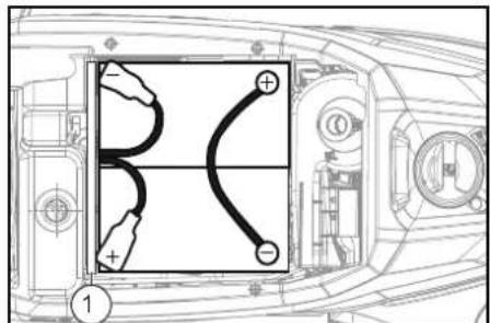
76 Ah, 2.815-099.0
① Penjarak
① Palam bateri, sisi peranti
② Palam bateri, sisi bateri
3. Sambungkan palam bateri sisi bateri ke pengecas.
4. Masukkan palam pengecas utama ke dalam soket
5. Jalankan proses pengecasan mengikut maklumat dalam arahan operasi pengecas.
6. Sambungkan palam bateri sisi peranti ke palam bateri sisi bateri.
Operasi
PERHATIAN
Keadaan berbahaya semasa operasi
Risiko kecederaan
1Skru
②Nat
③Timbang air
natural_image
Diagram showing a hand connecting a plastic tray with a coiled hose, indicating fluid or mechanical connection (no text or symbols present)natural_image
Technical line drawing of a mechanical assembly with no visible text or symbols① Penapis kotoran kasar
① Penutup tangki air tawar
② Penapis air tawar
① Cangkuk selak
② Apungan
③ Penapis bulu halus
④Perumah apungan

H. Jenner
Chairman of the Board of Management

S. Reiser
Director Regulatory Affairs & Certification
Penyelia dokumentasi:
S. Reiser
Alfred Kärcher SE & Co. KG
Alfred-Kärcher-Str. 28 - 40
71364 Winnenden (Jerman)
Ph.: +49 7195 14-0
Winnenden, 2019/01/25
目次
①サクションホース
②サクションバーサスペンション
③サクションバー
④クランプレバー
natural_image
Top-down schematic of a vehicle battery pack layout with no visible text or symbols115 Ah、2.815 091.0
80 Ah, 2, 815-090, 0
105 Ah, 2.815-100.0

76 Ab、2.815-099.0
①スペーサー
①ネジ
②ナット
③水準器
①ナット
②ワッシャー
③ホルダー付きスペーサーローラー
natural_image
Diagram of a flexible hose connecting a tray with a handle, showing directional arrows (no text or symbols)natural_image
Technical line drawing of a mechanical assembly with no visible text or symbols①粗いダートフィルター
①水用タンクの栓
②水用フィルター
2006/42/EG (-2009/127/EG)
2014/30/EU
2014/53/EU (TCU)
適用される調和規格
EN 60335-1
EN 60335-2-72
EN 60335-2-29
EN 62233: 2008
EN 55012: 2007 + AI: 2009
EN 61000 6 2: 2005
TCU (テレマティクス制御ユニット)
EN 300 328 V2.1.1
EN 300 330 V2.1.1
EN 300 440 V2.1.1
EN 301 511 V12.5.1
EN 62368-1:2014+A11:2017
使用国の規格

H. Jenner
Chairman of the Board of Management
S. Reiser
Director Regulatory Affairs & Certification
文書の全権委員:
S. Reiser
Alfred Kärcher SE & Co. KG
Alfred-Kärcher-Str. 28 - 40
71364 Winnenden (Germany)
電話番号:+49 7195 14-0

H. Jenner
Chairman of the Board of Management

S. Reiser
Director Regulatory Affairs & Certification
وكيل التوثيق:
إس رايزر
Alfred Kärcher SE & Co. KG
Alfred-Kärcher-Str. 28 - 40
71364 Winnender
Winnenden, 2019/01/25
natural_image
Technical line drawing of a mechanical component with labeled connection point (no text or symbols beyond the number 1)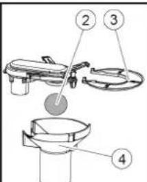
① خطاف thy—it
عوامة ②
③ مصفاة الوير
④ علبة العوامة
natural_image
Technical line drawing of a mechanical assembly with no visible text or symbolsnatural_image
Diagram showing a hand connecting a flexible hose to a device with directional arrows indicating movement (no text or symbols)①
فلكة ②
①برغى
② صامولة
③ ميزان الماء
5 حل الصامولة.
natural_image
Technical line drawing of a vehicle interior with no visible text or symbols099.0-2.815, 76
① الفواصل
① خرطوم شفط
② كمرة الشغط
③ كمرة الشفط
④ دراع القFTP
⑲٩ مشبك الخرطوم
natural_image
Black silhouette of a hand giving a thumbs-up gesture (no text or symbols)THANK YOU!
MERCI! DANKE! iGRACIAS!

Register your product and benefit from many advantages.
www.kaercher.com/welcome


Rate your product and tell us your opinion.
natural_image
Icon showing a gear and wrench inside a square frame (no text or symbols)www.kaercher.com/dealersearch
Alfred Kärcher SE & Co. KG
Alfred-Kärcher-Str. 28-40
71364 Winnenden (Germany)
Tel.: +49 7195 14-0
Fax: +49 7195 14-2212

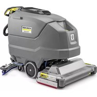


- Inhalt
- Contents
- General notes
- Function
- Note
- Intended use
- Environmental protection
- Notes on the content materials (REACH)
- Accessories and spare parts
- Scope of delivery
- Safety instructions
- △WARNING
- Device tipping over
- Safety devices
- △CAUTION
- Missing or modified safety devices
- Safety switch
- Key-operated switch
- Warning symbols
- Description of the unit
- Overview of the unit
- Colour coding
- Symbols on the device
- ATTENTION
- Installation
- Installing the suction bar
- Batteries
- Recommended battery sets BD 50/55
- Low-maintenance batteries (wet batteries)
- △DANGER
- Maintenance-free batteries (AGM and gel batteries) ATTENTION
- Installing and connecting batteries
- ① Spacers
- Removing the battery
- Initial startup
- Charging the battery
- Operation
- Filling with operating materials
- Filling with fresh water
- Notes on detergents
- Unsuitable detergents
- Detergent
- Adjusting the water volume
- Adjusting the suction bar
- Adjusting the inclination
- Adjusting the height
- Cleaning
- Switching on the device
- Driving
- Finishing operation
- Finishing cleaning
- Draining the waste water
- Improper disposal of waste water
- Quickly draining fresh water
- Transport
- Driving on slopes
- Failure to observe the weight
- Frost
- EU Declaration of Conformity
- Currently applicable EU Directives
- Harmonised standards used
- TCU
- National standards used
- Contenu
- ① Entretoises
- Indice
- ① Distanziatore
- Inhoud
- ① Distanciador
- Índice
- ①Espaçador
- Indhold
- Faresituation under driften
- ① Grovsi
- Batterier
- Anbefalte batteripakker BD 50/55
- Lite vedlikeholdskrevende batterier (våtbatterier)
- △FARE
- ① Avstandsholder
- Merknad
- Rengjøre grovsmussilen
- Anvendte harmoniserte standarder
- Innehåll
- Sisältö
- ①Αποστάτης
- İçindekiler
- ① Ara parça
- Содержание
- ① Проставка
- ④Корпус поплавка
- ①Távtartó
- ① Rozpěrka
- Kazalo
- Pribor in nadomestni deli
- Obseg dobave
- ①Przekładki
- ① Distantier
- Obsah
- ① Rozpierka
- Demontáž batérie
- ⚠UPOZORNENIE
- Sadržaj
- Akumulatori koji ne zahtijevaju održavanje (elektrolitski akumulatori)
- △OPASNOST
- ① Razmaknica
- Demontaža akumulatora
- △OPREZ
- Rad
- PAŽNJA
- Opasna situacija pri radu
- Punjenje pogonskih sredstava
- ①Vijak
- Matica
- ③Libela
- Podešavanje visine
- Napomena
- ①Matica
- ② Podloška
- Akumulatori sa malim stepenom održavanja (elektrolitski akumulatori)
- Dopunjavanje vode u ispražnjenom stanju akumulatora
- Upotreba vode sa dodacima
- Baterije kojima nije potrebno održavanje (AGM baterije i baterije sa gelom)
- Opasnost od oštećenja prilikom otvaranja AGM baterija i baterija sa gelom!
- ① Odstojnik
- Demontaža baterije
- ①Zavrtanj
- ②Navrtka
- ①Navrtka
- Brzo ispuštanje sveže vode
- Vožnja usponima
- Čišćenje mrežice za grubu prljavštinu
- Čišćenje filtera za svežu vodu
- Čišćenje plovka i mrežice za skupljanje vlakana
- Primenjene harmonizovane norme
- Primenjene nacionalne norme
- Съдържание
- ① Разпьваш елемент
- Sisukord
- Imitala monteerimine
- Akud
- Soovitatavad akupakid BD 50/55
- Akude hooldushaarad (märgakud)
- △OHT
- Saturs
- Piederumi un rezerves da las
- ① Distancers
- ①Spārnuzgrieznis
- ①垫片
- ①芯片
- ③間隔滾輪與支架
- 使用國家標準
- 자레
- 일반 지시 사항
- 부대 용품 및 예비품
- Isi Kandungan
- ① Penjarak
- Operasi
- PERHATIAN
- 目次
- 適用される調和規格
- 使用国の規格
- 文書の全権委員:
- THANK YOU!
- MERCI! DANKE! iGRACIAS!
Brand : Kärcher
Model : BD 5055 W Classic
Category : Scrubber