
EXACT 700 Professional - Screwdriver BOSCH - Free user manual and instructions
Find the device manual for free EXACT 700 Professional BOSCH in PDF.
| Brand | Bosch |
| Model | EXACT 700 Professional |
| Product type | Cordless industrial screwdriver |
| Max tightening torque (hard/soft) according to ISO 5393 | 8/8 Nm |
| No-load speed | 700 rpm |
| Rated voltage | 12 V |
| Weight according to EPTA-Procedure 01:2014 | 0.83 kg |
| Protection class | IP 20 |
| Power supply | NiCd/NiMH battery (9.6-14.4 V) or stabilized power supply via voltage adapter |
| Compatible battery type | NiCd 9.6/12/14.4 V, NiMH 9.6/12/14.4 V |
| Recommended charger | AL 2450 DV |
| Rotation direction | Right and left, selectable |
| Clutch | Yes, with torque preselection |
| Worklight LED | Yes, to illuminate the work area |
| Charge status LED | Yes, with acoustic signal |
| Tool holder | Quick-clamping chuck for 1/4" bits |
| Operating temperature | -5 to +50 °C |
| Relative humidity | 20 to 95% (non-condensing) |
| Sound level | 70 dB(A) typical, may exceed 80 dB(A) |
| Vibrations (screwdriving) | < 2.5 m/s², uncertainty K=1.5 m/s² |
| Maintenance | Cleaning of ventilation slots, lubrication of gear and clutch |
| Spare parts | Available via Bosch after-sales service |
| Repairability | Repair by authorized Bosch service center |
Frequently Asked Questions - EXACT 700 Professional BOSCH
User questions about EXACT 700 Professional BOSCH
0 question about this device. Answer the ones you know or ask your own.
Ask a new question about this device
Download the instructions for your Screwdriver in PDF format for free! Find your manual EXACT 700 Professional - BOSCH and take your electronic device back in hand. On this page are published all the documents necessary for the use of your device. EXACT 700 Professional by BOSCH.
USER MANUAL EXACT 700 Professional BOSCH
YkpaHcbKa ..CtoPiHa 159
Kaak. 5et 169
Româna...... Pagnia 178
Блгарск.. ..CtpaHua 187
MaKeDoHcN. CtpaHua 196
Srpski Strana 205
Slovenscina Stran 213
General Power Tool SafetyWarnings
WARNING
Read all safety warnings, instructions, illustrations and specifica
tions provided with this power tool. Failure to follow all instructions listed below may result in electric shock, fire and/ or serious injury.
Save all warnings and instructions for future reference.
The term "power tool" in the warnings refers to your mains-operated (corded) power tool or battery-operated (cordless) power tool.
Work area safety
- Keep work area clean and well lit. Cluttered or dark areas invite accidents.
Do not operate power tools in explosive atmospheres, such as in the presence of flammable liquids, gases or dust. Power tools create sparks which may ignite the dust or fumes.
- Keep children and bystanders away while operating a power tool. Distractions can cause you to lose control.
Electrical safety
Power tool plugs must match the outlet. Never modify the plug in any way. Do not use any adapter plugs with earthed (grounded) power tools. Unmodified plugs and matching outlets will reduce risk of electric shock.
- Avoid body contact with earthed or grounded surfaces, such as pipes, radiators, ranges and refrigerators. There is an increased risk of electric shock if your body is earthed or grounded.
Do not expose power tools to rain or wet conditions. Water entering a power tool will increase the risk of electric shock.
Do not abuse the cord. Never use the cord for carrying, pulling or unplugging the power tool. Keep cord away from heat, oil, sharp edges or moving parts. Damaged or entangled cords increase the risk of electric shock.
When operating a power tool outdoors, use an extension cord suitable for outdoor use. Use of a cord suitable for outdoor use reduces the risk of electric shock.
If operating a power tool in a damp location is unavoidable, use a residual current device (RCD) protected supply. Use of an RCD reduces the risk of electric shock.
Personal safety
Stay alert, watch what you are doing and use common sense when operating a power tool. Do not use a power tool while you are tired or under the influence of drugs, alcohol or medication. A moment of inattention while operating power tools may result in serious personal injury.
Use personal protective equipment. Always wear eye protection. Protective equipment such as a dust mask, non-skid safety shoes, hard hat or hearing protection used for appropriate conditions will reduce personal injuries.
Prevent unintentional starting. Ensure the switch is in the off-position before connecting to power source and/or battery pack, picking up or carrying the tool. Carrying power tools with your finger on the switch or energising power tools that have the switch on invites accidents.
- Remove any adjusting key or wrench before turning the power tool on. A wrench or a key left attached to a rotating part of the power tool may result in personal injury.
Do not overreach. Keep proper footing and balance at all times. This enables better control of the power tool in unexpected situations.
Dress properly. Do not wear loose clothing or jewellery. Keep your hair and clothing away from moving parts. Loose clothes, jewellery or long hair can be caught in moving parts.
If devices are provided for the connection of dust extraction and collection facilities, ensure these are connected and properly used. Use of dust collection can reduce dust-related hazards.
Do not let familiarity gained from frequent use of tools allow you to become complacent and ignore tool safety principles. A careless action can cause severe injury within a fraction of a second.
Power tool use and care
Do not force the power tool. Use the correct power tool for your application. The correct power tool will do the job better and safer at the rate for which it was designed.
Do not use the power tool if the switch does not turn it on and off. Any power tool that cannot be controlled with the switch is dangerous and must be repaired.
- Disconnect the plug from the power source and/or remove the battery pack, if detachable, from the power tool before making any adjustments, changing accessories, or storing power tools. Such preventive safety measures reduce the risk of starting the power tool accidentally.
- Store idle power tools out of the reach of children and do not allow persons unfamiliar with the power tool or these instructions to operate the power tool. Power tools are dangerous in the hands of untrained users.
- Maintain power tools and accessories. Check for misalignment or binding of moving parts, breakage of parts and any other condition that may affect the power tool's operation. If damaged, have the power tool repaired before use. Many accidents are caused by poorly maintained power tools.
- Keep cutting tools sharp and clean. Properly maintained cutting tools with sharp cutting edges are less likely to bind and are easier to control.
Use the power tool, accessories and tool bits etc. in accordance with these instructions, taking into account the working conditions and the work to be performed. Use of the power tool for operations different from those intended could result in a hazardous situation.
- Keep handles and grasping surfaces dry, clean and free from oil and grease. Slippery handles and grasping surfaces do not allow for safe handling and control of the tool in unexpected situations.
Battery tool use and care
- Recharge only with the charger specified by the manufacturer. A charger that is suitable for one type of battery pack may create a risk of fire when used with another battery pack.
16|English
- Use power tools only with specifically designated battery packs. Use of any other battery packs may create a risk of injury and fire.
When battery pack is not in use, keep it away from other metal objects, like paper clips, coins, keys, nails, screws or other small metal objects, that can make a connection from one terminal to another. Shorting the battery terminals together may cause burns or a fire.
Under abusive conditions, liquid may be ejected from the battery; avoid contact. If contact accidentally occurs, flush with water. If liquid contacts eyes, additionally seek medical help. Liquid ejected from the battery may cause irritation or burns.
Do not use a battery pack or tool that is damaged or modified. Damaged or modified batteries may exhibit unpredictable behaviour resulting in fire, explosion or risk of injury.
Do not expose a battery pack or tool to fire or excessive temperature. Exposure to fire or temperature above 130^ may cause explosion.
Follow all charging instructions and do not charge the battery pack or tool outside the temperature range specified in the instructions. Charging improperly or at temperatures outside the specified range may damage the battery and increase the risk of fire.
Service
Have your power tool serviced by a qualified repair person using only identical replacement parts. This will ensure that the safety of the power tool is maintained.
- Never service damaged battery packs. Service of battery packs should only be performed by the manufacturer or authorized service providers.
SafetyWarnings forScrewdrivers
Hold the power tool by insulated gripping surfaces, when performing an operation where the fastener may contact hidden wiring. Fasteners contacting a "live" wire may make exposed metal parts of the power tool "live" and could give the operator an electric shock.
Use suitable detectors to determine if there are hidden supply lines or contact the local utility company for assistance. Contact with electric cables can cause fire and electric shock. Damaging gas lines can lead to explosion. Breaking water pipes causes property damage.
Hold the power tool securely. When tightening and loosening screws be prepared for temporarily high torque reactions.
- Secure the workpiece. A workpiece clamped with clamping devices or in a vice is held more secure than by hand.
Always wait until the power tool has come to a complete stop before placing it down. The application tool can jam and cause you to lose control of the power tool.
In case of damage and improper use of the battery, vapours may be emitted. The battery can set alight or ex
plode. Ensure the area is well ventilated and seek medical attention should you experience any adverse effects. The vapours may irritate the respiratory system.
Do not open the battery. There is a risk of short-circuiting.
The battery can be damaged by pointed objects such as nails or screwdrivers or by force applied externally. An internal short circuit may occur, causing the battery to burn, smoke, explode or overheat.
Only use the battery with products from the manufacturer. This is the only way in which you can protect the battery against dangerous overload.

Protect the battery against heat, e.g. against continuous intense sunlight, fire, water and moisture. There is a risk of explosion.
- Switch the power tool off immediately if the application tool becomes blocked. Be prepared for high torque reactions which cause kickback. The application tool becomes blocked when it becomes jammed in the workpiece or when the power tool becomes overloaded.
WARNING
The dust produced by sanding, sawing, grinding, drilling and
other similar activities may cause cancer, congenital defects or genetic mutations. Some of these dusts contain substances such as:
Lead in lead-based paint and varnish; crystalline silica in bricks, cement and other building materials; arsenic and chromate in chemically treated wood. The risk of becoming ill depends on how frequently you are exposed to these substances. To reduce the potential danger, you should always wear adequate personal protective equipment (e.g. specially made breathing apparatus that can filter out even the smallest of dust particles) and work only in well-ventilated areas.
- Avoid switching on the tool accidentally. Make sure that the on/off switch is set to the off position before inserting a battery. Accidents can occur as a result of carrying the power tool with your finger on the on/off switch or inserting the battery while the power tool is switched on.
Do not use application tools that are worn or in otherwise less than perfect condition. Defective application tools can break, for example, causing material damage and personal injury.
When fitting an application tool, make sure that it is held securely in the tool holder. If the application tool is not held securely in the tool holder, it may become loose and consequently uncontrollable.
Be careful when screwing in long screws - there is a risk of slipping when using particular screws and application tools. Long screws are often difficult to control and there is a danger that you will slip and hurt yourself when screwing them in.
Check which rotational direction is set before switching on the power tool. If you want to loosen a screw but the rotational direction is set to tighten the screw, for ex
ample, the power tool may move violently and uncontrollably.
Do not use the power tool as a drill. Power tools with a shut-off clutch are not suitable for drilling. The clutch can shut off automatically and without warning.
Product Description and Specifications

Read all the safety and general instructions.
Failure to observe the safety and general instructions may result in electric shock, fire and/or serious injury.
Please observe the illustrations at the beginning of this oper-
ating manual.
Intended Use
The power tool is intended for tightening and loosening screws, bolts, nuts and other threaded connectors in the specified power and dimension ranges.
The power tool is not intended for drilling; in order to prevent personal injury and damage to property, power tools with a shut-off clutch should never be used for drilling.
Product Features
The numbering of the product features refers to the diagram of the power tool on the graphics page.
(1) LED indicator for screwdriving applications
(2) Battery charge LED indicator
(3) Rotational direction switch
(4) Battery release button
(5) Battery with APT contact
(6) On/off switch
(7) Marking ring
(8) Tool holder
(9) Application tool (e.g. screwdriver bit)
(10) Slider for preselecting the torque
(11)Charger
(12) Mains plug
(13) Green LED indicator on the charger
(14) Red LED indicator on the charger
(15) Connection socket for a voltage adapter on the 4EX-ACT
(16) D-Sub connector plug
(17) Screws on the D-Sub connector plug
(18) Voltage adapter
(19) Quick-change chuck
(20) Worklight
(21) Adjustment tool
(22) Setting disc
(23) Handle (insulated gripping surface)
A) Accessories shown or described are not included with the product as standard. You can find the complete selection of accessories in our accessories range.
Technical data
| EXACT industrial cordless screwdriver 246 | ||||
| Article number | 0 602 490 433 0 602 490 437 0 602 490 431 | |||
| Max. torque, hard/soft screwdriving application accord- ing to ISO 5393 | Nm | 2/2 4/4 6/6 | ||
| No-load speed n0 | min-1 | 600 900 600 | ||
| Rated voltage V 9.6 9.6 9.6 | ||||
| Direction of rotation | ΩΩ | ΩΩ | ||
| Weight according to EPTA-Procedure 01:2014 kg 0.82 0.83 0.83 | ||||
| Protection rating IP 20 IP 20 IP 20 | ||||
| EXACT industrial cordless screwdriver 7 8 9 | ||||
| Article number | 0 602 490 439 0 602 490 443 0 602 490 435 | |||
| Max. torque, hard/soft screwdriving application accord- ing to ISO 5393 | Nm | 7/7 8/8 9/9 | ||
| No-load speed n0 | min-1 | 150 680 350 | ||
| Rated voltage V 9.6 12.0 9.6 | ||||
| Direction of rotation | ΩΩ | ΩΩ | ||
| Weight according to EPTA-Procedure 01:2014 kg 0.87 0.87 0.83 | ||||
| Protection rating IP 20 IP 20 IP 20 | ||||
18|English
EXACT industrial cordless screwdriver 12 60 700 1100
| Article number | 0 602 490 441 0 602 490 469 0 602 490 447 0 602 490 471 | |||
| Max. torque, hard/soft screwdriving application according to ISO 5393 | Nm 12/12 5.5/5.5 8/8 4/4 | |||
| No-load speed n0 | min-1 | 400 60 700 1050 | ||
| Rated voltage V 12.0 9.6 12.0 9.6 | ||||
| Direction of rotation | ΩΩ | ΩΩ | ΩΩ | |
| Weight according to EPTA-Procedure 01:2014 kg | 0.87 | 0.83 | 0.83 | 0.83 |
| Protection rating IP 20 IP 20 IP 20 IP 20 | ||||
NiCd battery pack 9.6 9.6 12.0 12.0 14.4 14.4
| Article number | 2607335877 | 2607335659 | 2607335879 | 2607335375 | 2607335881 | 2607335655 |
| Number of cells | 8 | 8 | 10 | 10 | 12 | 12 |
| Battery voltage | V 9.6 | 9.6 12.0 12.0 14.4 14.4 | ||||
| Capacity | Ah 1.8 | 2.4 | 1.8 | 2.4 | 1.8 | 2.4 |
| Weight according to EPTA-Procedure 01:2014 | kg 0.45 0.50 0.65 | 0.70 0.70 0.80 | ||||
| Recommended chargers | AL 2450 DV | AL 2450 DV | AL 2450 DV | AL 2450 DV | AL 2450 DV | AL 2450 DV |
| NIMH battery pack | 9.6 | 12.0 | 14.4 | |
| Article number | 2 607 335 681 | 2 607 335 683 | 2 607 335 685 | |
| Number of cells | 8 | 10 | 12 | |
| Battery voltage | V | 9.6 | 12.0 | 14.4 |
| Capacity | Ah | 2.6 | 2.6 | 2.6 |
| Weight according to EPTA-Procedure 01:2014 | kg | 0.55 | 0.70 | 0.80 |
| Recommended chargers | AL 2450 DV | AL 2450 DV | AL 2450 DV | |
Noise/Vibration Information
Noise emission values determined according to EN 62841-2-2.
Typically, the A-weighted sound pressure level of the power tool is 70 dB(A). Uncertainty K = 3 dB. The noise level when working can exceed 80 dB(A).
Wear hearing protection
Total vibration values a_s (triax vector sum) and uncertainty K determined according to EN 62841-2-2: Screwdriving: a_n < 2.5m / s^2 K = 1.5m / s^2
The vibration level and noise emission value given in these instructions have been measured in accordance with a standardised measuring procedure and may be used to compare power tools. They may also be used for a preliminary estimation of vibration and noise emissions.
The stated vibration level and noise emission value represent the main applications of the power tool. However, if the power tool is used for other applications, with different application tools or is poorly maintained, the vibration level and noise emission value may differ. This may significantly increase the vibration and noise emissions over the total working period.
To estimate vibration and noise emissions accurately, the times when the tool is switched off or when it is running but
not actually being used should also be taken into account. This may significantly reduce vibration and noise emissions over the total working period.
Implement additional safety measures to protect the operator from the effects of vibration, such as servicing the power tool and application tools, keeping their hands warm, and organising workflows correctly.
Assembly
- Remove the battery from the power tool before carrying out work on the power tool (e.g. maintenance, changing tool, etc.). The battery should also be removed for transport and storage. There is risk of injury from unintentionally pressing the on/off switch.
Items included
Type
0602490437/0602490471/0602490447/ 0602490469
The industrial cordless screwdrivers are supplied without application tools, battery pack, battery charger, constant voltage regulator or voltage adapter. The voltage adapters
are to be used exclusively to connect Bosch industrial cordless screwdrivers to the 4EXACT constant voltage regulator.
Operating and storage conditions

The power tool is suitable only for operation at enclosed work sites.
To ensure smooth operation, the permitted ambient temperature should be between -5^ and +50^ (23^ and 122^) , at a permitted relative humidity of between 20% and 95% free of condensation.
The battery should be stored at a temperature of between 0 ^ C (32^) and 45^ (113^) in order to avoid damaging the battery cells.
Charging process
Note: Batteries and chargers not included.
The mains plug pictured here may differ from that on your power tool.
Make sure that the charger and battery are suitable for your country's mains voltage.
Charger AL 2450 DV (see figure A)
Connect the charger (11) to the power supply with the mains plug (12) and insert the battery (5) correctly into the charging slot on the charger.
Do not use force to insert/remove the battery. Batteries with APT contact (Akku Pack Top, English: battery pack top) are designed such that they can only be inserted into the power tool or charger in the correct position.
The green LED indicator (13) will start to flash. This indicates that charging current is flowing. The charging process will stop automatically once the battery is fully charged. When the charging process is complete, the green LED indicator will stop flashing and will be continuously lit. An sound is emitted for approximately two seconds, indicating that the battery is fully charged.
If the red LED indicator (14) is continuously lit, this indicates that charging is being carried out with a reduced charging current. If the red LED indicator is flashing, charging is not possible.
Errors - causes and corrective measures
| Cause Corrective measures | |
| LED indicators do not light up | |
| Mains plug of the charger is not (correctly) plugged in | Insert the mains plug (fully) into the plug socket |
| Plug socket, mains cable or charger defective | Check the mains voltage, have the charger checked if necessary by an authorised after-sales service centre for Bosch power tools |
Charging not possible
| Battery temperature outside the permitted range | Lower or raise the battery temperature until it is in the permitted temperature range |
Cause Corrective measures
| of 0°C (32°F) to 45°C (113°F) |
| Battery contacts are dirty Clean the battery contacts; e.g. by connecting and dis- connecting the battery se- eral times. Replace battery if necessary |
Battery defective Replace the battery
| Insert the battery (fully) into the battery charging slot |
Constant voltage regulator (see figure B)
Type
0602490437/0602490471/0602490447/ 0602490469
Note: As an alternative to battery operation, industrial cordless screwdrivers can also be operated with a constant voltage regulator. Constant voltage regulator and voltage adaptor not included.
The mains plug pictured here may differ from that on your power tool.
Make sure that the constant voltage regulator is suitable for your country's mains voltage.
In addition to the 4EXACT constant voltage regulator and compatible mains cable, you will also need a voltage adapter with the same rated voltage as your screwdriver.
The voltage on the constant voltage regulator (LED indicator) must match the voltage of the screwdriver. The constant voltage regulator is only suitable for Bosch industrial cordless screwdrivers from the EXACT, ANGLE EXACT and BT-EXACT series with a voltage of between 9.6 V and 14.4 V. Otherwise there is a risk of fire and explosion.
Connecting to the power supply
Note: On delivery, neither a battery nor a voltage adapter are inserted in the power tool.
- Never store batteries inside a battery-powered tool. Batteries will remain functional for longer and can be charged more easily if they are stored separately. Please remember to fully charge the battery prior to use after longer periods of storage.
Battery Charging
Charge the battery using a suitable charger before inserting it in the power tool. The charging process is described in detail in the charger's operating manual and the instructions of this manual (see (see "Charging process", page 19)).
The battery features NTC temperature monitoring, which only permits charging in a temperature range between 0^ (+32^) and 45^ (+113^) . This achieves a long battery life. If used correctly, the battery can withstand up to 3000 charging cycles.
A new battery or one that has not been used for a long time will only operate at full capacity after approximately five
charge and discharge cycles. Batteries should only be charged if the battery charge LED indicator on the power tool lights up red.
Inserting and removing the battery (see figure C)
Push the rotational direction switch (3) into the middle position. This locks the on/off switch (6) in the "Off" position and prevents the power tool from being switched on unintentionally.
Push a charged battery (5) into the handle of the power tool. Make sure that you insert the battery correctly and that you can feel the release buttons (4) engage in the handle of the power tool.
Do not use force to insert/remove the battery. Batteries with APT contact (Akku Pack Top, English: battery pack top) are designed such that they can only be inserted into the power tool or charger in the correct position.
To remove the battery (5), press the release buttons (4) on both sides and pull the battery down and out of the handle.
Inserting and Removing the Voltage Adapter (see figure D)
Type
0602490437/0602490471/0602490447/ 0602490469
Select the voltage adapter that matches your power tool's rated voltage.
The voltage adapters can be differentiated by the colour of the housing of the D-Sub connector plug (16), which differs according to voltage. The housing of the D-Sub connector plug for a voltage of 9.6V is light blue, the one for a voltage of 12V is red.
The adapter housing (18) may only be fitted on or removed from the industrial cordless screwdriver when the constant voltage regulator is switched off or when the connector plug (16) is disconnected from the constant voltage regulator.
Push the rotational direction switch (3) into the middle position. This locks the on/off switch (6) in the "Off" position and prevents the power tool from being switched on unintentionally.
Then push the adapter housing (18) into the handle of the power tool. Make sure that you insert the adapter housing correctly and that you can feel the release buttons (4) engage in the handle of the power tool.
Then insert the connector plug (16) for the voltage adapter that is compatible with your power tool into the connection socket (15). Tighten the connector plug (16) in the connection socket (15) by hand-tightening the two screws (17).
To remove the voltage adapter, loosen the two screws (17) on the connector plug (16) of the constant voltage regulator (switched off) and remove the connector plug from the connection socket (15).
Then press the release buttons (4) on both sides and pull the adapter housing (18) out of the handle of the power tool.
Changing the tool - screw head with quick-change chuck (see figure E)
When fitting an application tool, make sure that it is
held securely in the tool holder. If the application tool is not held securely in the tool holder, it may become loose and consequently uncontrollable.
Inserting the application tool
Pull the quick-change chuck (19) forwards. Insert the application tool (9) into the tool holder (8) and release the quick-change chuck again.
Only use application tools with a matching shank (1/4" hexagon).
Do not attempt to insert drill bits into this quick-change chuck. Industrial cordless screwdrivers with a shut-off clutch are not suitable for drilling. The clutch can shut off automatically and without warning. If you continue drilling after the clutch has shut off, the power tool may be wrenched out of your grip until the shut-off clutch engages again.
Removing the application tool
Pull the quick-change chuck (19) forwards. Take the application tool (9) out of the tool holder (8) and release the quick-change chuck again.
Operation

Use personal protective equipment. Always wear eye protection. Protective equipment such as a dust mask, non-skid safety shoes, hard hat or hearing protection used for appropriate conditions will reduce personal injuries.
Starting Operation
Always set the rotational direction using the rotational direction switch (3) before starting the power tool:
The power tool will not start if the rotational direction switch (3) is in the centre (lock-off button).
Setting the Rotational Direction (see figure F)
Only operate the rotational direction switch (3) when the power tool is not in use.
Clockwise: To drive in screws, press the rotational direction switch (3) all the way to the left.
Anti-clockwise: To loosen or unscrew screws, press the rotational direction switch (3) all the way to the right.
Switching on the LED worklight (see figure G)
The worklight (20) illuminates the work area in poor lighting conditions. Switch on the worklight (20) by lightly pressing the on/off switch (6). If you press down harder on the on/off switch, the power tool will switch on and the worklight will remain illuminated.
Do not look directly into the worklight; it can blind you.
Switching on/off

The screwdrivers have a torque-dependent shut-off clutch that can be set to a value in the specified range. It activates when the set torque is reached.
Note: If you are operating the screwdriver with a voltage adapter, you will need to put the constant voltage regulator into operation first.
To switch on the power tool, press the on/off switch (6) down fully.
The power tool will switch off automatically when the set torque is reached.
If the on/off switch (6) is released too early, the preset torque will not be reached.
Practical advice
- Remove the battery from the power tool before carrying out work on the power tool (e.g. maintenance, changing tool, etc.). The battery should also be removed for transport and storage. There is risk of injury from unintentionally pressing the on/off switch.
Only apply the power tool to the screw/nut when the tool is switched off. Rotating tool inserts can slip off.
Setting the torque (see figures H-I)
The torque depends on the spring preload of the shut-off clutch. The shut-off clutch is triggered upon reaching the set torque, both in clockwise and anti-clockwise rotation.
Only use the supplied adjustment tool (21) to set the individual torque.
- Slide back the slider (10) on the power tool fully.
- Place the application tool (21) into the tool holder (8) and turn it slowly.
- Once a small protrusion (setting disc (22)) in the clutch can be seen through the opening of the housing, insert the adjustment tool (21) into this protrusion and turn it.
Turning clockwise will result in a higher torque; turning anticlockwise will result in a lower torque.
- Remove the adjustment tool (21). Slide the slider (10) to the front again to protect the clutch from contamination.
Note: The required setting is dependent on the type of threaded connector and can be best determined by practical trials. Check a trial screw application with a torque spanner.
If you set the torque to a value outside the specified power range, the shut-off clutch will not be triggered.
Marking the torque setting
To label individually set torques, you can replace the marking ring (7) with a marking ring of a different colour. If you use certain EXACT power tools with a torque of 4.5 Nm, for example, you can fit red marking rings on these to identify the set torque. If you use other EXACT power tools in a different assembly area with a torque set to 7.5 Nm, you can fit a marking ring of a different colour (black, blue, green or yellow) to identify the torque in this area. The different marking ring colours are only intended as an aid for fitters to facilitate identifying the set torque on a specific power tool.
Press the marking ring (7) with a thin screwdriver blade, a spatula or similar implement.
Always use the power tool with a marking ring to be certain that the housing is protected against dust and dirt.
LEDindicator

Battery charge indicator
If the battery (5) needs to be charged, the LED indicator (2) flashes green and a sound is emitted. You can only drive in six to eight more
screws.
If the LED indicator lights up red, there is not enough capacity left to drive in another screw or the power tool has overloaded. The power tool can no longer be switched on. The lock-off function remains active until the drained battery has been removed from the power tool and a charged battery inserted.
If you are working with a voltage adapter, the red LED (2) indicates overloading.
A significantly reduced operating time of the power tool after charging indicates that the battery must be replaced soon. Dispos of depleted batteries in accordance with legal/country-specific provisions.

Indicator for screwdriving applications
The shut-off clutch is triggered upon reaching the preset torque. The LED indicator (1) lights up green.
If the preset torque has not been reached, the LED indicator (1) lights up red and the tool emits a sound. The screw must be driven in again.
Repeat protection
If the shut-off clutch is triggered while driving a screw, the motor will switch off. You will need to wait 0.7 seconds before you can switch the tool on again. This prevents you from accidentally retightening screws that are already firmly in place.
Maintenance and Service
Maintenance and Cleaning
- Remove the battery from the power tool before carrying out work on the power tool (e.g. maintenance, changing tool, etc.). The battery should also be removed for transport and storage. There is risk of injury from unintentionally pressing the on/off switch.
To ensure safe and efficient operation, always keep the power tool and the ventilation slots clean.
Lubricating the power tool

Lubricant:
Special gearbox grease (225 ml)
Article number 3605430009
Molykote grease
Motor oil SAE 10/SAE 20
- Clean the gearbox with a mild solvent after the first 150 operating hours. Follow the solvent manufacturer's instructions on use and disposal. Then lubricate the gear
22 | English
box with Bosch special gearbox grease. Repeat the cleaning process once every 300 operating hours after cleaning has been carried out for the first time.
After driving 100,000 screws, oil the moving parts of the shut-off clutch with a couple of drops of SAE 10/SAE 20 motor oil. Lubricate the sliding and rolling parts with Molykote grease. Use this occasion to check the clutch for wear to ensure that accuracy and reproducibility have not been affected. You will need to reset the clutch torque once you have done this.
Have maintenance and repair work performed exclusively by a qualified specialist. This will ensure that the safety of the power tool is maintained.
An authorised Bosch after-sales service point will handle this work quickly and reliably.
- Dispose of lubricants and cleaning products in an environmentally friendly manner, taking legal regulations into account.
After-Sales Service and Application Service
Our after-sales service responds to your questions concerning maintenance and repair of your product as well as spare parts. You can find explosion drawings and information on spare parts at: www.bosch-pt.com
The Bosch product use advice team will be happy to help you with any questions about our products and their accessories.
In all correspondence and spare parts orders, please always include the 10-digit article number given on the nameplate of the product.
Great Britain
Robert Bosch Ltd. (B.S.C.)
P.O.Box 98
Broadwater Park
North Orbital Road
Denham Uxbridge
UB95HJ
At www.bosch-pt.co.uk you can order spare parts or arrange the collection of a product in need of servicing or repair.
Tel. Service: (0344) 7360109
E-Mail: boschservicecentre@bosch.com
Ireland
Origo Ltd.
Unit 23 Magna Drive
Magna Business Park
City West
Dublin 24
Tel. Service: (01) 4666700
Fax: (01) 4666888
Australia, New Zealand and Pacific Islands
Robert Bosch Australia Pty. Ltd.
Power Tools
Locked Bag 66
Clayton South VIC 3169
Customer Contact Center
Inside Australia:
Phone: (01300) 307044
Fax: (01300) 307045
Inside New Zealand:
Phone: (0800) 543353
Fax: (0800) 428570
Outside AU and NZ:
Phone: +61 3 95415555
www.bosch-pt.com.au
www.bosch-pt.co.nz
Republic of South Africa
Customer service
Hotline: (011) 6519600
Gauteng - BSC Service Centre
35 Roper Street, New Centre
Johannesburg
Tel.: (011) 4939375
Fax: (011) 4930126
E-mail: bsctools@icon.co.za
KZN - BSC Service Centre
Unit E, Almar Centre
143 Crompton Street
Pinetown
Tel.: (031) 7012120
Fax: (031) 7012446
E-mail: bsc.dur@za.bosch.com
Western Cape - BSC Service Centre
Democracy Way, Prosperity Park
Milnerton
Tel.: (021) 5512577
Fax: (021) 5513223
E-mail: bsc@zsd.co.za
Bosch Headquarters
Midrand, Gauteng
Tel.: (011) 6519600
Fax: (011) 6519880
E-mail: rbsa-hq.pts@za.bosch.com
Disposal

The machine, rechargeable batteries, accessories and packaging should be sorted for environmental-friendly recycling.

Do not dispose of power tools and batteries/ rechargeable batteries into household waste!
Only for EU countries:
According to the Directive 2012/19/EU, power tools that are no longer usable, and according to the Directive 2006/66/EC, defective or used battery packs/batteries, must be collected separately and disposed of in an environmentally correct manner.
Battery packs/batteries:
Ni-Cd: Nickel cadmium
Warning: These battery packs contain cadmium, a highly toxic heavy metal.
Ni-MH: Nickel metal hydride
Français
Protection antiredemarrage
Calle Robert Bosch No. 405
C.P. 50071 Zona Industrial, Toluca - Estado de Mexico
Tel.: (52) 55 528430-62
Tel.: 8006271286
Ni-Cd: nickel-cadmio
Bosch Service Center
Telegrafvej 3
2750 Ballerup
Pá www.bosch-pt.dk kan der online bestilles reservedele el-ler oprettes en reparations ordre.
TIf. Service Center: 44898855
Fax:44898755
E-Mail: vaerktoej@dk.bosch.com
Bortskaffelse

Ni-Cd: Nikkel-cadmium
Bosch Service Center
Telegrafvej 3
2750 Ballerup
Danmark
Tel.: (08) 7501820 (inom Sverige)
Fax: (011) 187691
Avfallshantering

Robert Bosch Sp. z o.o.
Bosch Service Center PT
K Vapence 1621/16
692 01 Mikulov
Na www.bosch-pt.cz si si muzete objednat opravu Vaseho stroje nebo nahradni dily online.
JHMA Hn CpeCTB 3aHTbOprAHOB CnyxA, B3aBNCMOCTN OT Bnda pa6ToBc 3NEKTPoHCTpyMeHOM CHHXKaETPNC NOnyueHn TpaBM.
IpeoTbpaaTe HnpeDnHapepeHoe BKnIOueHne 3NEKTPOHCTPymeHa. Peep TEM KAK NOkNIOUHTb 3NEKTPOHCTPymeNT K cETn /nn K AKKyMnyrTOpy, NODHTb nnn nepehoCHT b3NEKTPOHCTPymeT, y6eITcEcb, YTO OH BBkIOUey. YdepKaHne NaIbca Ha BblKIOUaTeI np TpAHCnOPTnPOBKe 3NEKTPOHCTPymeTA I NOkJIIOUeHHe K cETn IITaHNA BKNIOUeHHO 3NEKTPOHCTPymeHTa YpeBaTO HeCuaCTHBIMn CnyaAMN.
y6npaTe yctahOBouhI hNCTpyMeH IIN raeuHbIe KIOUHO BKIOUeHHN 3NEKTPoHNCTpyMeHa. INCTpyMeHT NIN KIOU, HAXOJauHcBO BpaAioUeIcYacTHN 3NEKTPoHNCTpyMeHa, MOKeT pNBecT K TpaBMam.
He npHmMaTe HeecTeBcHHeO nOIOKeHne Kopnyca Tena.Bcerda 3aHMMaTe yToOnuHBoe nOIOKeHne H coxpaHnTe paBHOBeCHe. BnaIgApA rTOMy BbMoKTe LyUwE KOHTpOJInpOBaTb 3JNeKTpOnHCTpyMeH T HeoxHN DaHHbxCITyaCnX.
Hocnte noxoxnyo paobuyo odexy.He hocnte 1npokyo odexy H ykpaewen. Depknte BOncbI n Odexy BdaNOT NOBnKhbIX DeTanei. Wnpokar oE- kda, ykpaewen INN dINHHbIe BONCbMOryt 6bItb3aTAYtB BpaaOuMNMCYaCTAMN.
Pn HAnuHn BO3MOxHOCTN yCTaHOBKn PbIeOTcAbBaOuNX N PbIEc6OpHBx yCTPOJcTB npOBepaHTe NpHCoEHNHeHne N ppaBnIBHOe HCNoB3OBAHne. PnMeHeHne PbIeOTcoca MOXET CHN3HTb ONaCHOCTb, CO3daBaEMyIO PbIbIO.
XopoOee 3HaHHe 3NeKTPoHnCTpymeHOB, nOlyueHHO Bpe3yIbTaTe yAcTOrO Hx HcNoIb30BaHnH, He DoNkHO npHBODHTb K CaMOyBepeHHocTH N rHrOpHPOBaHNO TexHNKn 63oNaChOCTn 6paUeHnC 3NeKTPoHnCTpyMeHTAM. OJHo He6pexHoe DeIcTBHe 3a DOnIO cekyHdb MoKET pINBecTn K cepbe3HbIM TpaBMam.
BHIMAHHE!Bcnyae Bo3nHKnHOHeHH nepe60Bpa6oTe 3NEKTPOHNCTPymeHTA BCNECDTBne NOHORO HnH qACTHNOI pKePaueHH 3HePROChABxHHeHH NnIOBpeXDeHHuENynpaBHeHH 3HePROCHABxHeHHem yCTaHOBNTe BbIKNoTuTeHB NNOXKeHHeBBkL. y6eINBUnCb,TO OH He 3abloKpOBaH (npn erO hAnuHH).OTKIOUHTe CTeByO BVILKY OT PO3ETKN INN OTCoeHNHITe CBEMhBI AKKMyJrTOp.3TNM PpeDToBpaAaETcRA HeKOHTPOnpyEmbl IOBtOPHbI 3anyck.
PpHmEHeHHe 3eKtpOnHcTpymEHTa H o6paueHne c HMM
He neperpymaTe 3neKtpoHnCTpymEnT. McnoIb3yTe Dnpa p60tbI COOTBETCTBYIOUc CNEUAnbHbN IeK- TPOHNCTpymENT.C NOxOJRAuHM 3neKtpoHnCTpymEHOM Bby pa6otaete Nyue H naEckhee Byka3AHOM dnaana30- He MOUHOCTN.
He pa6oTaTe c3neKtpOnHCTpyMeHToM npn Hnc- npaBHom BbIKIOuATEne.3NeKtpOnHCTpyMeHT, KOTOpbl He noJaaeTcBAKIIUeHHIO INN BbIKIOueHHIO, ONaCeH n D0JIKeH 6bIb OTpeMOHTnpoBaH.
IpeepTeKakHactpaHaBt3eKeTPOHNCTpyMeHT,3a MeHrtbPnHaNDexKHOCTHNNy6HpTa3eK- TPOHNCTpyMeHT HaXpaHeHne,OTKNIOHTe WTeNCenb-HyBOuNKy OTOPETKCETH N/NNBBHBe,ecN3TO BO3MOXHO,AKKMyJITOp.3aMepaPepOCTOPOXHOCT HpEDoTBApaAet HepeDHaMepeHHoe BKNIOueHHe 3eKeTPOHNCTpyMeHTa.
XpaHNTe 3NEKtpOHNCTpymENTbIB HeIOCTynHOMdIaTeMce.He pa3peuAte NOB3OBaTbC3NEKTPOHNCTpymENTomnUcAm,KOTOpBleHe3NAKOMblCHMMnHHeHTANHactOuaHxHCTpyKu.3NEKTPOHNCTpymENTbONachbIBpykaxHEoTHbIXnUc.
TuaTeNbHO yXaxxHBaIte 3a 3neKtPOHnCTpyMeHToM npHaadJeXHoCTaMn. PIOBepaIte 6e3ynpeHyo fYHKcHIO XOD ABHXUxxCaJtceT 3neKtPOHnCTpyMeHTA, OTCyTCTBHe NlONMOK HIN NOBpeXdHm, OTpuTaTeNbBO BnHIOuNX Ha fYHKcHIO 3neKtPOHnCTpyMeHTA. NOBpeXdHbIe YAcTH DoNkHbI 6bITb OTpeMOHTpOBaHbI Do HcNoB30BaHHa 3neKtPOHnCTpyMeHTA. IIOxoe 06cnyxHBaHne 3neKtPOHnCTpyMeHToB AIBaETcPnPHHO 6OJIbIoro UHCNa HeCuaCThIx Clya-EB.
DepxHTe pexyHn HNCTpyMeHT B 3aTOueHHom HnCTOM COCTOHH.3a60TINBO yXoXeHHbIe pexuyne HHCTpyMeHTb C OCTpbIMpexyuHHKpOMKaHHpeXe 3aKNHBAOTCA INXJFGE BECTH.
PpHmHeHte 3eKtpOnHcTpymEt, pHnHaJnxHoCTn, pa6OHe HcTpyMeHbI N. T. B COOTBeTCTBn C HAcTo- aUHMn HcHTpyKUaMn. YUHTbBaTe npn 3tOM pa6o- yCIOBn H BblONHReMyo pa6Oy. IcNoJIb3ObaHne 3eKtpOnHcTpymEtOB HnpeDycmOTpeHHbIX pa60T MOKeT PpNBecrN K ONaChbIM CNTyaUaMn.
DepxHTe pyuKN H NOBepxHOCT3aXbATA cyXHM HcH CTbIMN, CJIeNTe 4TO6bl HA HNX 4TO6bl HA HNX He 6blNO XKNDKOHN KOHCnCTeHTHO CMa3Kn. CkOB3Ke peyuKN H NOBepxHOCT3aXbATA npenATCTBYOT 6e3OanChOMy 06paueHHo C NCHCTpyMeHToM H He daIOT HaedKHO KOHTPOHPOBaTb eRO B HENpeDVBHeHHBX CHTyaunx.
PpHMeHeHne H6cnyXnBaHne AKKymyIaTOpHOro HHCTpyMeHTA
3apkaTe aKymnTOpbl TOnbKO B 3apHbIX yctpoiCTBax, peKomeHdyembIX h3rTOBHTenEM.3apHoe yctpoiCTBO, npdycmOTpeHHOE dIg ONpeDeneH HOro Bnda akkMyJrTOPOB, MoKet pNBeCTN K NOxapHOI ONaCHOt nPi HcNoJIbSOBaHN erO c DpyHMn AkkMyJr Topamn.
PnMHeHBe 3NeKtpOnHCTpyMeHTax TOnbKO npEy-CmOTpeHHbe IINr3TOAkkymyIaTOpbI. NcNoB3OBA-Hne DpyHX aKKMyIaTOpOB MOKeT pNBeCTN K TpaBMAM IN NOXapHOI ONaCHOCTN.
3aunuane HeHcNoB3yEmbAkkymnTOpOT KaH-uePCKHX CKpeNOK,MOHeT,KNUoei,ΓBO3eI,BHNTOB HpyrHx ManEhKHX Metannuecknx PpeMeTOB, KOToPbIE MOrY3akopoNTb NIOca.KoPoTKoe 3aMbikAHne NOIIOCB AKKymnTOpO MAoKet npHBecTN KOKoTaM HIN NoXAp.
PnHnepaBbHOMHCNoB3OBAHNn3aKKyMnyIopap MoKet noteyb KndKocTb. N36eaiTe cOpNKoCHOBeHH C Hei. PnCnuyaHOM KOtAKTe npomoiTe COOTBETCTByIOUeE MeTO BOIOE. EcN 3Ta KndKocTb nonaDet B rna3a, To DOnONHtEnbHO o6paTHecb K bpauy. BbTEkaOua aKKyMnyIaTOPHaJg KndKocTb MoKet npBeCTN K pa3DpaKeHHIO KOx INN K OXkOrAM.
He hcnb3yIte nobpeXdeHbIe Hn N3MeHeHbIe AkKymyIaTObpI Hn HNcTpMyEnTbI. NobpeXdeHbIe Hn N3MeHeHbIe aKKymIaTObpI MOrT NOBcTn Ce6a HeInpedCKa3yEmO, YTO MoKeT pINBeCTN K Bo3rOpaHHo, B3pBiY nPi nPCKy IOnuyeHn TpaBMbl.
He KnaIte aKkyMnyTOp Hn HNCTpyMeH B OROh Hne NOBepraTe HX BO3eJCTBIO BbICOKHX TEmpeAtp. OroH bnn Tempepatya Bblwe 130°C MoryT npBeCTN K B3pblBy.
BbINOHnTe Bce HNCTpyKuHn No 3apRkne H He 3apRkaIte aKKyMnyTOp HIN HNCTpyMeNT npi TempeAtype, BbIXOJaSe 3a YKa3aHHb IB NCHCTpyKuHn DnaHa3OH. HenpaBnBHa3 3apRkA Hn 3apRkA npi TempeAtypax, BbIXoJxHx 3a YKa3aHHb DnHa30H, MOrTy NOBpeDHT bataeHO nOBbcITb pNC BO3rpaHn.
CepBnC
Pemont 3neKtpOnHcTpymeHTaDJIKeH BbINONHtBcT OJbKO KBaIINHcNpOBAHbIM NepcoHAnOM TOnbKO C npMHeHHem OpRnHaHbHix 3anacHbIX qactE.3TN M obecneuBaetc63oNaChocTh 3neKtpOnHcTpymeHTa.
HnKOrJa He 06cIyXnBaIte NOBpeXeHHeIbe aKKymMyIaTOpbI. O6cIyXnBaTb aKKymIaTOpbI pa3peJaaTeC8 TOJIbKO IPOIN3BOJNTENIO HN ABTOPI3OBAHHo CepBnCHOn OPraHn3aUHN.
Yka3aHnnoTeHXnke6e3oNaChocHTdna WypynOBepTOB
PnBbINHHeHHpa60,piN KOtOpbIX Wpyyn MoKet 3aTeTbCKpbIyTO 3NEKTPOPNBOQky,dEpxHTe HnCTpyMeHTaH3ONHPOBaHHBe NOBepxHOCTn.IpepezAHne HaxOJaIeOcnoHnPaJKeHHem 1hypa MoKet 3apA HnTb MeTaNueCkHe qAcTH 3NEKTPOHNCTpyMeHTa NpHBeCTn K yDapy 3NEKTPOueCkHM TOKOM.
McnoB3yTe COOTBETCTBYUHne Metannnckatenn IIN HAXOXJENH CNPTAHNbIX B CTEne Tpy6 HNN npoBODKN HNN O6paauTecb 3a CnpaBKO B MeCTHOKOM MyHalbHOe PpePnHtne. KOHTAKC 3NeKTponpOBOI-KOIMoKTe pNBecTH K NOXApY NopaxHeHIO 3NeKTPOKOM. NobpeKHeHne ra3OpOBoDA MOKeT pNBecTH K B3pbBy. NobpeKHeHne BOIDOPoBA BeDeT K HaHeceHHIO MaepnaHbHO ruepe6a.
Kpeno depknte 3nEkpOHnHcPymENT. Pn3aTnBaHN HN N OTnyCKAHIN BINTOB/UPyPNOB MOrY BO3HnKaTb KpaTKOBpeMeHHBle BBICOKNE peAKUHOHbIe MOMHTbl.
3aKpennnre 3arotOBky.3arotOBka,yctaHOBneHHa B 3axMMHoe npncno6neHne nN B TnCKn, ydePKBaetc 60nee HndexKnO, qem B Baew pyke.
BbIXdTe nonHoi ocTaHOBKN 3neKTPoHNcTpymenta H TOIbKO nOcNE 3Toro BbInyckaJIe erO h3 pyk. Pabouhi
HHTpymeHT MoKET 3aeCTb, H 3TO MOKET pNHBcTH K IOTepe KOHTPOHaH 3JekTPOHHCTpymeHTOM.
PnIOBpeKdHnn HHeaIeKaIeM HcNoIb3OBAHHn aKKymyIaTopa MoKet BblJeNHTbcra3.AKKymyIaTOp MOKET BO3rOpA TcR Hn B3pIbA TbC8.O6ecneuTbe npnTOK CBeKeero BO3dyxa n Pn BO3HKnHOBeHH nn06 6paTHTecb K BpaU. Ta3bl MOrY TbB3BaTb pa3dpaxKeHne DblaXaTeNbHbIX NpyTe.
He BcKpbBaIte aKKymyTOp. Ptn 3Tom BO3HnKaET ONaCHOCTb KOPOTKOrO 3aMbIKAHnA.
OctpbIMn PpeMeTaMH, KaK HAp., rBo3dEm HnH OBeTKoH, a TaKKe BHeWHHM CnIOBbIM BO3dEChTBHE MoXHO NOBpeHTb AKKyMnyIaTOpHpyo 6aTapeo.3To MOKeT npIBeCTN K BHyTpEHHEMy KOPOTKOMy 3aMbIKaHHIO, BO3rOpAHIO C 3aDbIMHeHEM, B3pby Nn NepepeBy akKymyIaTOpHno 6aTapei.
NcnoIb3yIte aKKymnIaTOpyIO 6aTapeIO TOnbKO Bn3- DeHx n3rOToBntEn. TOnbKO TaK aKKymnIaTOp 3auu- uEN OT ONaCHOI neperpy3Kn.
3aunuanteakkymnytohpno6atapeo0T BbICOKNXTemnepaTp,Hanp.,OTdNTenbHO rHarpBaHHaCoHNHe,OTOrH,BODB BlaH.CyueCTByeTOnacHocThB3pbIbA.
HemeHHeHO BbIKIOHTe 3NEKTPOHCTPymeHT,ecn pa6oHm HNCTpMeHT 3aKNHHNO. Bynde roTOBb K BbICOKHM peAKTNHBIM MOMHTAM,KOTOpbIe npHBODT KOTDAue.Pa6oHm HNCTpMeHT 3aKNHHBaET pni nepepy3ke 3NEKTPOHCTPymeHaNN 3aCTpeBaHH INHCTpMeHTA B6pa6aTBaEMO 3aTOBKe.
NPEyPENKDEHNE
IbIb, KoTopa o6paayetc npn 06pa6oTe haxkaKom, pacnnBaHH, HhfoBKe, CBepneHHH
noobbix pa6oax, moKet 6bIb KaHcpeoreHHoB, BpeHoh nn nOda Hn H3MeHbT reHtueckn MaTePnA. B acCTHOCTN, nbInb MoKET cOePkaT bCneDyUOuNE BeuecCTBa: CBnHeuC B Kpackax N NaKax; KpNCTaJInuCeCKN KpEmHezEM B KpNHe, ZemeHTe N IpOuX MaTePnAanx, KOtOpBie npImeHIOCT Pn IN KlaOuHbIX pa6oTx; MblsBk IN XpOMaTb I B o6-pa6oTaHHoXmIKaTAMn DpeBeCnHE. Pnck 3abOnBeBAHN 3aBNCNT OT TOR, KAK aCTO Bbl NodBepraINCB O3dEICTBNO 3THX BeueCTB. IN YMeHbWeHn ONaCHOCTN Heo6xOJMoPa6oTaB XoPoTO pOBeTPBaEMbIX NOMEeEHnx IN CnONb3OBaTB COOTBETCTBYUOuNE CpeDCTBA INHINBIVyaJIbHOH 3aUnTIb (Hanp., CneuaNBHy peCnnpaTOp, KOTOpBIOfHn TPOBbIAeT MeJIbCuAnuNe YAcTHNuIbII).
PpeoTbpaaTe cnyaHoe BKnOueHne. Y6eHntecb, 4TO BbIKNoaTeB HxOOnTCB NNOXKeHH BbIKI.. nepeD TEM KAKCTBaNtB aKKMynTop.HoWeHne 3NeKTPoINHCTpyMeHTa C NaJIbEeMa HbIKIOuTaTele HnYcTAHOBka aKKMynTOpA BO BKIOUeHHb 3NeK- TPOINHCTpyMeHT MoJEBcTN K HeCuaCTbIM CnyaAM.
McnoIb3yTe TOnbko HcnpaBHBie, He N3HOweHbIe pa60ue HHCTpyMeHTbl. NobpeXdeHHbe pa6ooyne HcTpyMeHTbl MOrY, HanpIMep, NOIOMaTBca IN pNVBecTN K TpaBMam MATEpHaNbHOMy yUep6y.
PnH yctahOBKe cMeHHoro paobOero HHCTpymenta CNEIHTe 3a TEM, YTO6bI OH NIOTHo cen Ha NaTPOH. Ecnn pa
6oHn HnCTpyMeHT He HMeet npOuyOH CBA3n c NaTPOHOM, TO OH MoKET pa360ntaTbCn BByTHn H3-NOk KOHTPOJ.
BybTe BHNMaTeNbHbI npn 3aBopauHBHH dHHHbIX BNHTOB/WHpyNOB:B 3aBNCMHoCTN OT THNa BnHTA/WHpyNA HpNHMeHemoro pa6Oero NcHcPymeTA cyueCTBYET ONACHOCTb TORO,TO WyyPN MOKET COCKONb3- HTb. DHHHbIE BnHTb/WHpyNt bYactO HeBO3MOKHO HaCTOnbKO KOHTPOPiPoBaTb, YTObI NCKJIouHTb ONACHOCTC COCKaJIb3bIBaHH I TpaBMnPOBaHH pNp 3aBOpauHBHH
Peped BkHoueHem 3NeKtpOHCTpyMeHa npOBepbTe yctaHOBHeHoe HappaBHeHne BpaSeHH. Ecn, K npHmepy, WpypN Heo6XoHMo OTnycTb, a HApBaBHeHne BpaSeHH NaCTpoEHO TaK, YTO WpypN 6yDet 3akpyuBAtbC4, 3NeKtpOHCTpyMeHT MoKET peKo DepeHyTbC4, YTO NOBneET yTpAly KOHTPOJIa.
He npmeHnTe 3neKtpoHHCTpyMeHT B KaueCTBe DpeHn. 3neKtpoHHCTpyMeHTbI C OKIIIOuAIOUeMyΦToH He nproHbI dna CBepNEHn. MyΦTa MoKET ABOMaTHueCKN OKIIIOuATbc6e NpdeynpeXeHn.
Onncahne npoodykta n ycnyr

IpoHTHe Bce yka3aHHN HnHCTpyKcHn No texHKe 6e3oNaChocTn. HecobnoJeHne yka3aHn ITO TexHKe 6e3oNaChocTn INHCTpyKcHn MOKeT nPbBeCTn K npaKeHHIO 3NeKtpuYeCKHM TOKOM, NOkapy N/IN TAnKeBbIM TpaB
MaM.
Ioxanycta,coBIOdaIte HIOCTpaunB Hauane pykoBOOCTBaNo 3KcNpyataun.
PpMHeHnNoHa3NaeHHIO
Hactoii 3eKTPOHCTPymENT npedHa3HaueHnI 3aBopaaBHHN BbBOPaunBaHHN BHTOB/ uypynOB,raek npyoro pe3b60BOrO KpeEnka BYkazAHOM dnaana3OHe pa3mepOB. Hactoii 3eKTPOHCTPymENT He npiroDeHnI NCIOB-30BaHHB KAecTe DpeJI; DNpnpOTBpaUeHHaHaHeceHHyBEuH NIOJIM BeIeCTBeHHORO yIep6a HIKoRda He npimehiTe 3eKTPOHCTPymENT C OTKnUoyauOe MyfToI nnCBepNeHH.
H3o6paXeHHbIe COCTaBHbIe Yactn
Hymepaun npedctabHeHHbIX KOMIOHETOB BblONHeHaNo H3opaKeHHo Ha cTpaHnue C NllIOCTpaHnM.
(1) CBeToDnOuHbI HnHnKaTOp 3aBopauBaHn
(2) CBeToIOHbI INHnKaTOp 3apJKeHHocTn aKKyMynaTopa
(3) IpeeknioateHbHaPaBneHHBaPaeHH
(4) KhoNka pa36nokOpOBKa aKKMyTotaA
(5) AKKMyIaTOp CO WTeNcENbHbIM KOHTaKToM APT
(6) BbiknioyateIb
(7) MapKInpoBouHoe KOJIbIcO
(8) NpToH
(9) Pa60yHnHCTpyMeHT (hanp., 6nta)
(10)ДВИЖОКУCTAHOBKIN KPYTAJISeRo MOMeHTa
(11)3apdHoeyctpoCTBO
(12)UtencenbA
(13) 3eHbCBeToDnOHyB HNdkaTOp Ha zapdHom yctpoiCTBe
(14)KpaChbINCBETOINODHbINHHNkATOpHa3apAnOM yCTPOINCTBe
(15)PnncoeHHHtBHe rHe3do dna aanTepa HanpJKe-HHa 4EXACT
(16)UTekep D-Sub
(17) BnHTbHa uTeKepe D-Sub
(18) AdaanTep HanpJxKeHHa
(19)БыICTpo3aЖIMHNOI NaTPOHa
(20) Iopcbetka
(21)HactpoeHbHnHCTpyMeHT
(22) yctahohooyhaa
(23)PyKoTka(cH0nIpOBaHHoNIOBepXHOCTbO)
A) N3o6paXeHHbIe Hn onncaHbIe npHaadJeXHoCTHe BXOaRtB cTaNdPtBIObEIM NOCTABKn. IOnHbI accOPTMENT npHaadJeXHoCTe BbHaNdTe BHaWeI npPorpAmme npHaNDJeXHoCTe.
Texnueckne daHbIe
PpmbiHnHHb aKcymyIaTOpHb bInrToBept EXACT 789
| Мakc. Крутыши мочent пу paBOTе в ќесTKH/МЯГКИ мaterиалх по ISO 5393 | H·M 7/7 8/8 9/9 | |||
| Число кoleбани нахолocTom xodу n0 | MнH-1 | 150 680 350 | ||
| Hominaьhoe habржени B 9,6 12,0 9,6 | ||||
| Нарравлие воршени | ΩΩ | ΩΩ | ΩΩ | |
| Masca corlaclarno EPTA-Procedure 01:2014 kr 0,87 0,87 0,83 | ||||
| Стениь зашины IP 20 IP 20 IP 20 |
PpmbuHnBuAkkymyIaTophBbNHTOBePT EXACT 12 60 700 1100
HactoJn 3neKtpOnHCTpyMeT nprnoeH NcKIOHTeBHO DnE KcNpyaTuHN B3aKpbTbIX NOMeHEnx.
Длгбунрун go p60tbldoynctmaHemnepaTypaokpykaOuSe CpeBdI OJINKHa HaxoNtbcB B DnApa3OHe OT-5°Cdo+50°C (OT 23°F Do 122°F) npH doynctmoh otHocHTenbHOB BlaXHOCTn BO3dyxa ot 20 Do 95% Be3 BInaDeHHPOcbI.
XpaHnTe aKKymyIaTOp npI Tempepatye O T 0^ (32^) 45°C (113°F) BO H6eKaHne NOBpeKdEHHa aKKymyIaTOpHbIX 3JeMeHTOB.
Ipocecc3apnkn
Yka3aHHe:3apnHbIe yCTpoiCTBa n AKKMyIaTOpbl He BXO-1R T B KOMJIeKT NocTaBKN.
H3o6paKeHHa BnIka ceTH MoKet OTNuaTbC8 OT BnIKHa BaWem 3neKtpOHCTpymEHTe.
CneIe3aTeM,HTO6bl3apAHOe yCTpoHcBO nAKKMyrTOp NOxOHNn DnN MeCTHOn 3NeKTPOCeTH.
3apnHoe yctpoictBO AL 2450 DV (cm. pnc.A)
IopknHouTe 3apAnHoe yctpoCTBO (11) BnKnOy (12) K cetN 3JeKTPoNTaHn I BCTaBbTe aKKMyTAp0p (5) npaBnBHO CTopoHO B 3apAnHoe rHe3do 3apAnHoro yctpoCTBa.
Pn yctahOBKe/N3BneueHHN AKKyMnyTOpH06atapeH He npimeHnTe CNY. AKkyMnyTOpbI CO WTeNCJIbHbIM KOHTaKToM APT (Akku Pack Top) ycTpoEhblTaKMnO6pa3OM, YTO OHN CTAHOBrCBAeKTPoHnCTpMyENT HIN3apHHOyeCTPO TOnkBO BnpabunbHom IIOJoxEHn.
3enehBcBETNOHbHINHnKaTOp(13)HaunHaetMnraTb. 3TOROBOPHTO NOCTyynHeHHN3apJHOroTOKa.IPOeCC3 apJKNABOTMAHueckn NpeKpaauTeC, KORdaAKKymIaTOp 10NHOCTbIO3apJxHe.NoCTOBHbCBET3eNEHO CBETO HNOHOro HNDkaTopaYkAsBaET Ha OKOHuaHne Ipoceca 3apJKn.3BykoBoi CnHAn PpOOnJXHTeHBOCTn OK.2 cek ROBOPHT O NOHON 3apJxHeHHCTNaKKymIaTOpa.
IocTOrHHoe CBeueHHe KpaCHOrO CBeToNDHOr HnDnKaToPa (14) roBOpHT O 3apJKe aKKyMnyTOpa NOnHKeHHbIM ToKOM. Ecn KpaChbN CBeToNDHbN HnDnKaTOp Mnaet,TO 3apJaKa HeBO3MoJHa.
Henolana -Pnunnnbnyuystpahene
PnpuHaYcTaPaHHe
AkkymyIaTOp HeHcnpaBHe 3aMeHIne aKKymyIaTOp
H3bTnHaanTepa HnpanKeHHOBHTe 0bHTa (17) Ha npncoeHHENTbHOB INKe (16) NOKIOUeHHORO CTaHIN3aTopa HapnKeHHN BbIHbTe npncoeHHHTbHyIO BNky nPncoeHHHTeBOrIg3da (15).
3aTeM HaxMNTE C o6eHX CTOpOH Ha KhoNk Pa3bNOKpOBKN (4) N BbITHHTe aAnTep (18) n3 pyKOaTKn 3neKTPOHnCTpyMeHTa.
3aMeHa cMeHHoro pa6oeryo HHCTpyMeHTa npn roJOBKe wypynOBepTa c 6bICTpo3aXHMhIM natPOHOM (cm. pnc. E)
PnH yctahOBKe cmEHoro paobOero HNCTpymenta CNEIHTe 3a TEM, YTO6bI OH NIOTHo cen Ha NaTPOH. Ecn npa
6oHn HnCTpyMeHT He HMeET npOuHO CBA3n C nAtpOHOM, TO OH MoKet pa3bONTaTbCn BByTHn H3-NOk KOHTPOJ.
YctahOBka pa6oery HnCTpyMeHa
IOTAHHTe 6bICTPOCMeHHbI NaTPOH (19) BnpeD. BcTaBBte CMeHHbI paOouH INCTpyMeHT (9) B NaTPOH (8) H ONrTB OTNCTHe 6bICTPOCMeHHbI NaTPOH.
NcnoB3yTeToIbKOcmEHbIe paOouHnHCTpyMeHTbIC IOxOIAUMXBOCTOBHKOM(WecTHrpaHHK1/4").
He nbItaTeCb yCTaHOBnT bCepNo B3OT 6bIcTPOcMeHHbI nataPOn. PpomblueHhble aKkyMylrTopHbe BNHTOBepTb C OTKnIOUaOuSeMyfTo He npiroDhl dNc CBepnEnHa MyTa MoKeT aBTOMaTHueCKH oTKIOUaTbC6e3 ppeynpeJeHna.Ecn Bb NocBe bIKIOUeHMyfTb 6yTe daIbWe cBepnTb, To 3NeKTPOINHCTpyMeH T moKET bIPBaTbCa y Bac n3 pyK, noka OTKnIOUaOuJMyfTa eue pa3 cpaBoTaet.
N3BneueHHe HnctpyMeHa n3 NaTPOHa
NotAHnTe 6bIcTpOcmEHnBn NaTPOH (19) Bnpeq. N3BnEKeHTe CmEHnBpaOouNHCTpyMeHT (9) n3 NaTPOHa (8) nONrTB OTNCTHe 6bIcTpOcmEHnBn NaTPOH.
Pa6ota c HhctpymehtOM

PpHmEnHrTe CpeDCTBa HnHbNduyAaBHO 3aunTb. BcerDa HocHTe 3aunTHbIe OcKn.
HcnoIb3OBAHHe CpeCTB HnINBHyaJIbHOHa 3a- uHTb, KaKTo: 3auTHOH MaCKn, o6yBN Ha HeCKoIb3AueH nOoWBe, 3auTHoro WJema
HIN CpeDCTB 3aunTbI OpraHOB Cnyxa, B 3aBNCMHOCN OT BNda pa6oTbC 3neKtpOHCTpyMeHTOM CHnKaET PnCK NOnyehn Hn TpaBM.
BknoueHne 3nEeKtpOnHcTpymeHa
IpepeBkUoyehEm 3neKtpoHnCTpyMeHTa Chauana yctahOBtte HnpaBHeHne BpaueHnC NOMOu bIO nepeKluoyatela (3):
3JIeKTPoHnCTpyMeHT He BkNIOuAetC, KOrDa nepeKIOUaTeNb HAnpaBHeHn BpAuEHH (3) yCTaHOBHeB CpeHHee NIOJKeHHe (6IOKnPaTOp BkNIOueHH).
HactpoKa HapnpaBHeHH BpaueHHa (cm.pnc.F)
PnBODHTe BdEChTBne NepeKIOuATEb HAnpaBNeHn BpaueHHa (3) TOnbKO npOcTaHOBNEHOM 3Iek- TPOHNCTpyMeHTe.
PpAboe BpaueHHe:JnIaBnHnBaHnHaWpyNoB nepeDInbTe peKeKnOuAteIb HapPaBneHn BpaueHn (3)doynopa BnEBo.
Ibeoe BpaueHHe: IaonOTnyckHaHHn OTBnHnBaHHn 7ypynoB nepeBnHbTe nepeKIOuataeH HanpABneHn BpaueHHN (3)doynopa BnpaBO.
BkHoueHne noCDBeTKn (cm.pnc.G)
PnDCBtKa (20) nO3BOJAEOT CBeaTa pa6ouyIO 3OHy npH HeoCTaTOUHOM O6eEM OCBEeEHNN. PnDCBtKa (20) BKIOuAeTc IERKHM HAXATHE M BbIKIOUATEI (6). Pn6Oone CNbHOM HAXATHN Ha 3OT BBKIOUATEIb BKIOUaeTc 3NEKTPoINHCTpyMeHT n pa6Oee OCBEeEHNN npOOnXaET CBeTNTb.
He cmotpnte npma Ho nOcBETky, oHa moKet Bac ocIenHb.
BkJIOueHHe/BbIKIOueHHe

UppynOBepHTMeetOTKIOHouOyIO MyfTy, KOTOPa Cpa6aTbIbAeB Yka3aHHOM DnAna3oHe B 3aBNCIMOCTH OT KpyTAeRO MOMENTa N HcCTpanBaETC B 3aDAnHom DnAna3oHe. OHa cpa-6aTbIbAe TpN DOCTHXEHN YCTAHOBNEHHORO
KpyTaeIeFo MOMeHTa.
Yka3aHHe: Pnp pa6ote C nHTaHHem OT cTa6nHn3atopa Hnpanjxehn CHaayana BKNIOUHTe CTA6nHn3atop.
ДлвькIOUeHЯЗЛКТРОИСТPyMeHTa HαKMITE BbIKIQUaTeNb(6)doynopa.
3NeKTPoHHTpyMeHT BbIKNHOaETcABTOMaTHueCKn npn DOCTHXeHHYcTaHOBHeHHOr KpyTuaero MOMHa.
Pnp npexkdeBpeMeHHOM OTnycKaHH BBKIOHauTea (6) yctAHOBHeHHb KpyTmM OMeHT He DoCTHraeT C.
Yka3aHnno npImMeHHIO
Do hauana pa6ot no Texo6cnyKBAHHO, CMeHe HnCTpyMeHTa T.Д., a TAKKe Ipn TpaHcNOpTHpOBKe H XpaHeHH N3BNeKaTe AKKyMnIaTOp 13 3eK- TPOHHCTpyMeHTa. PIn HnpeHaMepeHHOM BKNIOeHHN BO3HnKaet OAnCHOctb TpaBMnpOBaHH.
YcTaHaBnBaTe 3NEKtpOHNCTpymeHt Ha BnHT HnH raKy ToIbKO B BBIKIOUeHHOM COCTOHH. Bpaauo- uHeecpa6oOhnHCTpymeHt bMOrT cCKoJIb3HyTb.
HactpoKa KpyTaeO MOMeTa (cm.pnc.H-1)
KpyTAMOMENT3aBNCHTOTnpedBapntbHOrHOanpXeH NpyxNBIpa3MbkaIOSeMyΦtI.MyΦTa cpa6aTbBaet KAKPnPiPABOM,TAKNJIeBOM HANpABNeHN BpaUeHIN Pn DOCTHXeHHYcTaHOBNEHHORO KpyTJero MOMHTA.
HnactpoKn HnDnBnDaJbHOro KpyTaeTo MOMeTa HC- nOJIb3yIte TOnbKO npINarAOuNc HAcTpoeHbIn NcHTpyMeHT (21).
-ПОЛHOCьTOOTTЯнITEHa3aIДВИЖOK(10)Ha3eK-TPOINHCTPymEHTe.
- BCTaBbTe HAcTpoeHbI INHCTpyMeHT (21)ВгHe3doДЯ pa6Oуero INHCTpyMeHTa (8)И MedInHIO NOBOpauHbAte ero.
KakToIbKO BOTBepCTHKn KOpnyca CTAHET BnHO He6oIbIooe yIy6bnHe (yCTaHOBOUHaJ Waa6a(22)) BMyΦTe, BCTaBtE B Hero HAcTpoeUHbINHCTpyMeHT (21) INOBEPHITe.
BpaueHne no yacoBoi cTpeKe yBeHHuBaet KpyTaun MoMeHT, BpaueHne npOTnB YacoBoi cTpeKn CHNkae T kpyTaun MOMeHT.
-ⅢBnKeHt HAcTpoeHbH NHTpyMeHT (21). ChOBA npeDnHbTe DnKOK (10) Bneped, TTo6bl 3aunNTb MyfTy OT 3aqr3HeHH.
Yka3aHHe: Tpe6yemaHaCTpoKa 3aBnCHT O BnDa pe3b6oBOrO coeHNHeHn HnyuIe BCero ee onpeJeTb HenOpceIcTBENHO no XoHy pa60tBu. Pp6Hoe coeHNHeHne npOBepNTb DHHAMOMETPHueCKM KIOUOM.
HactpaHbaIte KpyTmH MOMeHToBko Byka3aH HOM dHaNa3OHe, TaK KaK HHaYe pa3MbikAIOuaMyΦTa He 6yDen cpa6aTbIBaTb.
MapknpoBkHaCTpOikKn KpyTaeo MOMeTa
YTo6bI Oo3NaHTb HnHnBnDyAaJIbHO HaCTpOeHHbKpyTtIOMMeHT MoXHO 3aMeHHTb MapKnPOBOUHOe KOnbIO JDPYTORO CBeta.
Ecni Bbl, HanpHmep, HcnoIb3yeTe HeckoJIbKO 3neKTPOnHCTpyMeHTOB EXACT C KpyTAAIM MOMENTOM B4,5H·M,TO Bbl MoXeTe yctaHOBtB kpaCHbe NOMeTOUHbE KOJIbCaJINIO6O3HaueHHBaWero KpyTAAEYO MOMETA. EcnBblNCIOJIb3yeTe Ha dpyrom MOtAaXHom yactKe eue HeCKoJIbKO 3NEKTPOnHCTpyMeHTOB EXACT, KpyTAAIM MOMENT KOToPbIXyCTaHOBHeN Ha7,5H·M, TO Bbl MoXeTe HcNoJIb3OBAbT NOMeTOUHbE KOJIbCa DpyrTO OZeta JINIO6O3HaueHHKpyTAAEYO MOMETA Ha 3TOM yactKe. NOMeTOUHbE KOJIba pa3hBXzEBOTB IpeDyCMOTpeHb TOnJIbKO KaN NOMOuBdIA NOHTepOB, YTO6bbl IMETB BO3MOXHOCTb 6bICTPO ONPeDEINb YCTaHOBLeHHb KpyTAAIM MOMENT COOTBeTCTBYIOE 3neKTPOnHCTpyMeHTA.
OTBepTKoCToHKIMIINuCEm,IINaTeNEmHIN TOMyIOIObHBIM INHCTpyMeHOTOM CHINMTe MAPKINPOBOUHOE KOJIbO(7).
Bcerda nconb3yTe 3neKtpOnHcTpymeHT cMapKnpoBouHbIM KOBtOM, yTO6bIb 6bITb YBepeHHbIM, yTO Kopnyc 3aun-uenOT nbIN 3aqrA3HeHNI.
CbeToHnOHaN HnDnKaa

HndkaTop 3apJxekHeHocTh aKKymyIHTopa
Pn Heo6xOdmocTh 3apAnk AkkymnyTopa (5)CBTeODNoHbI HnDnKaTOp (2)Mnrae T3e-HehBIM CBETOM pa3daetc3ByKOBo CnHaJ.
B TaKOM cnUyae MOxHOb BbIOnHHTb eIe He 6oJIe 6-8 coEHNHeHn.
EcHn CINHnHKaTOp CBETnCkpaCHbIM CBETOM,To EMKOCTn He XbaNT nIHOBOrO CoeINHeHHN HNI 3NeKTPoHNCTpyMeHT neperpyKeH. 3NeKTPoHNCTpyMeHT HeBO3MOxHO BKIOuHTb. BLOKNPOBKa BbIKIOUaTeIa OCTaeTCa AKTNBHO, NOKa AKKyMnyTOp 3NeKTPoHNCTpyMeHT He 6yDet 3aMeHeH 3apJKeHHbIM aKKyMnyTApOM.
Pn pa6ote c aadantepom HapjKeHH KpaHb CBeToNDHOHb HnDKaTOp (2)CnHaHn3HypeTnepepy3ky.
3HaunTbHoe cokpaueHne npoJOnKHeTbHocTH pa60tI nocne 3apKn yka3bBaet HA cTapeHne aKKyMnIaTOpa Hno6xoImocb ercKopo3ameHbl. Otpa6OtaBnE aKKyMnIaTOpb CneDyET YtnHmIPOBaT coNacHO 3aKOHbIM/ CneuHbIM dA CTpaHbI NIOKeHHM.

HdkaTop 3aBopauHBnA
PnDocTnxEHH npEdbapnteHbHO hAcTpoEH HOro KpyTaueo MOMeha cpaabaBaeT pa3MbkaHoaMyfTa.CBeToHOnHbI HnHnKaTop
(1)CBETHTCA3eHehBIMUBETOM.
Ecnn npedyctaHOBHeHHb KpyTAAH MOpHT He DoCTHRHT, CBToNDIOHb HNDAKATOP (1) 3aropaaTcKpaChbIM CBeTOM n pa3daeTc3BykoBo CNrHaJ. Oepaunzo3akpyuBaHnryhkyNoTOBTOPtB.
3aunTaOT NOBTOpeHHN
Ecni BO Bpem3aBopauHbAHnca6oTaIpa3MbkaIOua MyΦTa,TO BBKlIOuaeTcraTakKe INBnRaTeNb. NOBtropHoe BKIOUeHHe BO3MOXHO TOnbKO Nocne Na3bl npOIoXnTeNb-HocTBIO 0,7ceyND.3mM Bbl npDeOTbPauaete CnyaHHe NOITARIBaHHe yke 3aTAYtbix CoeINHeHn.
TexobnyxHbAHne n cepBnC
Texo6cnyxHBaHne nOuNCTka
Do hauana pa6ot no Texo6cnyxHBaHHO, CMehe HnCTpymEna n T.Д., a TaKKe pNTPaHcnpTbPOBKe m XpaHennn N3BNeKaTe AkkymyIHTOp n3 3eK- TpOHnCtpymEna. Pn HnpeHaMepeHHOM BKNIOueHNN BO3HNKaeT OAnCHOCt b TpaBMnPoBaHHA.
Длгобсесуеня Каecтбeнйи 6e3oNaChо Pa60TbI coepKHTe 3JIeKtpOnHcTpymEIT N BeHTNlaHnHbIe npope3N B uHcTOTe.
Cma3Ka 3JIeKTpOHHCTpyMeHTa

Cma30uHbMaTepeHaI:
CneuNbHa TpaHCMnCCNOHn Cma3Ka (225 M)
ApTkyIbHbI HOpE 3605430009 MoHKOTOBa CMa3Ka
MToTPhoeMacnoSAE10/SAE20
-Посспеспьбх 150 pa6oунх уacob ouchntite peуктор cna6bim pactBopHTenem.Ceунte yka3aHm n3rOToBNTeЯ pactBopNTeNo npImeHEnIO uYTHn3aun.ПocSе 3TOrO cMaKbTe peykTOp CneuaJIbHOH peykTOpHOc mazkoB Bosch. Посспеспьоунх ouchntkn NOBtOPaIte 3Ty npocdupy c HHTepBaONb M 300 pa6ouyx cacOB.
-Пибл.поссг 100000 onepaци зakpyuBaHЯ смазы BaITe NOBnKhIbe DeTALMyfTbHeCKOblkMn KaIIAMN MOTOPHOro Macla SAE 10/SAE 20.CkOB3aJHne I KaTaoUcHecr DeTAL Heo6XODmO cMa3bIBaTb MoNKOTOBO CMA3Koi.ПиЗТоВОзMOxHOCTH ПОБеррTe MyfTy Ha N3Hoc,чTObI NOyUHTb YBepeHHOCb B Co6JIOpEHHN NOBTOPRAEMCTH INTOHOCTH BbIKIOUeHIn.Поссг 3TORO cIeDyET 3AHOBO yCTaHOBTb KpyTuaMOMeHT MyfTbI.
Pa60tI NO texo6cnykHBaHmIO pemOHry pa3pewaetCnPON3BOOHTb TOnbKO KBaINHpHnPOBaHHbIM CneuAnHCTam. 3THM o6ecneuHbaTc 6e3onacHOCTb 3NeK-TPoHNCTpyMeHtA.
CepBnchra MaTePcKaa HmBb Bosch BInonHReTakyio paBoTy 6bIcTpo HAdexHo.
Cma30hIbe MaTePnAbI h CpeCTBa IIN OUHCTKN DOnXHbI yTmN3HPOBaTBc3KoONrHuCeCKN UChTBIM 6pa3OM.BbInonHHe npeDncaHHa3aKoHOdaTeNb- CTBa.
CepBnKoHcyNbTHpObaHne no BOpocam npMeHeHHA
CepBnchbI OTenOTBeHT Ha Bce Baun Bonpocbl no peMoNTy n 06cnykBaHIO BaWero npOdykta, a TaKoe no 3anJaCTM. N3o6paXeHHa cnpctpaHCTBeHHbIM pa3deneHHemDenateH HnHΦopMauHIO nO 3anJAcTMMoKHO NoCMOTpeTb
TAKKe no aDpeCy: www.bosch-pt.com
KoNneKTHB COpydHnKOB Bosch, npedocTabIouu KOnCytbTaun Ha npedMeT NcNoJIb3OBAHIN npOyKUn, C yDobOBCTBmE OTBeNT Ha BCE BaUN BONpOcBi OTHOCTeNBHO Haue npOdyKUn N ee npHaNDexHocTe.
IopkaanyiTa,BO Bcex 3anpocax n 3akazax 3anuacteY o6raTeBbHO yka3bBaIte 10-3NaHbTobapHbH HOpE no 3aBODCKoTbIuKHeN3denn.
ApmenHn,A3ep6aJxKan,Ipy3n,KpRn3ctan,MoHroIHH,TaXKNKCTAH,TypkMeHNCTAH,Y36KeNCTAH
TOO «Pobepr Bow» (Robert Bosch)
Power Tools nocennpodaakhoe o6cnykubnne npocneK TaBm6eka 169/1
050050 AnMaTbI, Ka3aXCTaH
Cnyke6haa 3n. nouta: service.pt.ka@bosch.com
OΦηιαλβήν Βe6-caɪT: www.bosch.com, www.bosch- pt.com
Ytnnn3aun

3NeKTPoHCTpyMeHtbl,akkyMyIaTOpHbIe6batapei, npHaJnEJeXHoCTm yIaKOBky HxKHO cdaBaTa hHa 3KOLOrHueCckn YHCTyO peKynepaIIO.

He Bb6paBbIaTe 3neKtponHCTpyMeTbI n AkKymyIaTOpHbIe 6batapeN/6batapeKN B 6bITOBOMycop!
AkkymyIaTOpbl/6aTapeH:

Ni-Cd: HNKeIb-KaDMHeBVe
BHHMaHHe:DaHbIe aKKMyIaTOpblcOepKataKaMmN - BBICOKOTOKCnHbI TReKeJIbMeTaN.
Ni-MH: HNKeJIb-MeTaN-TIaDnIhIe
yKpaIHcbka
Bka3iBkn 3Texhikn 6e3neKn
3araanbHI BkazIBKN 3TexHIKN 6e3neKn dIeNEKtpoiHCTpyMeHTIB
NONEPE- DKEHHA
IpoountaTe BcI Bka3iBKN 3Texhikn 6e3neKn,InctpyKu,InIOCTpaQTa Ta cneunphiau,Haadi 3 uH
eneKtpoiHcTpymeHTom. HeBnKoHaHHyycix noaHHx
HnKue iNcTpkyiM MoKe Ipu3BecTH Do ypaXeHHA
eKeTpuHmCTpymom, noKejki i/ab6 cepno3HOI TpaBM.
160|YkpaHcbka
I6pe 36epiraTe Ha Maia6yTHc i nonepdxheni Bka3iBKn.
ПД NOHATTAM (eNEKTPoIHCTpyMeHT) B cIx 3aCTpeKeHHax MaTbCnHa yBa3i eNEKTPoIHCTpyMeHT, IIO npauOe BiD mepexi (3 eNEKTPoKa6eM) a60 bId akymyIaTOpHOI bataei (6e3 eNEKTPoKa6eNIO).
PpnuHa YcyHennr
CbitnoioDi hiHdkaTopn He cbitraBc
| He (nobHicItro) BCTpOMLeHn штencelb зардного псирю | (Dobpe) BCTaВte wTeNceьу po3eTKy |
| HecnpabHa po3etka, kaběnl Живлесни abo zaradni присри | П配电ipte Hanpyru в мерекi Та за Heo6xIzhnicTo 配电ipte zaradni 配电ipte в crepbichni Мajстордя ЕlektrpoIHcTpymEnTiB Bosch |
3apdKaHHH HEMOKNBE
| Temnepaypsakymajtorpoi 6batapei no3aMEXAMN Donyuctmoro diana30Hy | OxonodgenHAm aboHarpibAHNM DoBeidTbTemnepaTypy akymajtorpoi 6batapei do donyuctmoro diiana30Hy BiD 0°C (32°F)do45°C (113°F) |
| 3a6pydHHINCS KONTAKTNakymajtorpoi 6batapei | OuHCTITb KOHTAKTNakymajtorpoi 6batapei;Hapr., DekiIbka pa3iB BCTPOMITb i BVNImitbakymajtorpHu 6bataeIo, 3aNotpe6n 3amHITbakymajtorpHu 6bataeIo |
| AkymajtorpHa 6bataperHecnpaBHa | Помине akymajtorpHu 6bataeIo |
PnHHaYcyHeHH
AkymyjTOpHa 6aTapeHn (NOBHcTHo) BCTpOMNeHa
(NoBnicto) BCTaBe
akymnyatophy 6aTapeIO B
3apJrHe rH3do
Cta6ini3atop Hanpyr (mB. Man. B)
Tm
0602490437/0602490471/0602490447/ 0602490469
Bka3ibKa: Ppomncnobi akymnytophi wpynpokpytn mokytb npauOBaTN Rk BiD akymnytropHOI bataei, taK i Bid cta6in3atopa Hanpyr. Cta6in3atopn Hanpyr i aadntepn Hanpyr He BXoJrTB KOMIIeKT NocTaBKn.
3o6paekhen wTencenb moKe BiDiPi3HrTnC BId wTencenHa BaWOMy eneKtpoiHcTpymEtI.
Cnikkyte3aTHM,06cta6ini3atopHanpyrH6yB npdaTHN Dn MepeKi Baoi KpaHn.
Kpim ctabiniaTopa Hanpyr 4EXACT Ta BiJNOBIDHoro shypa JKNBHeHH,Notpi6HH aadTep Hanpyr 3 taKoIO caMOHO HOMHaHbHOH anpyro, k y BaWoro 0wypynokpyta.
HanyraHaCTabini3atopi Hanpyn(INB. CBITNOIOHN IHNKAtoP)MaBIDNoBIdaTHanpy3I wypynokpyta.Ctabi3atop Hanpyn npnaHaeHH BNIIOUHO nIPOMNcNOBX akyMnyTApOHx WypynokpytB Bosch cepii EXACT, ANGLE EXACT i BTEXACT 3 HanyroIO BID 9,6Bdo14,4B.BiHOMy BnadKy icHy eHe6e3neKa noKeji i Bn6xy.
PikKIOUeHHoDJKepeNaXHBnEHNA
Bka3iBka: Bynb nacka, 3BepHb yBary Ha Te, 0o aHI akymyIaTOPHa 6aTapea, aHI aanTep Hanpyr niD vac NOCTABKN He E BCTPOMHeHMn B EeEKeTPOIHcTPymENT.
HikonHe 36epiraTe akymyTApOhi 6aTapei B akymyTApOHOmy eNkTpoIHcTpMentI.
AkymynTOpHnx 6batape BnCTaue HaIOBwe i BOHN KpaIe 3apJdxKaIOTbcra, kIIO BOHN 36epiraIbC8 OKpEmo. RaIoo akymynTOpHa 6batape IOBRIuac He 6yBaPbTe NOBHcTIO 3apJNTII.
3apxkannn akymnytopho6aatae
Ipeep THM, RA BCTaBHTN akymyTApHy 6aTaapeo B
eneKTPOiHCTpyMeHT,3apRiTiB II B npDAtHomy 3apRiHOMy
npiCtPOi. TouHn ONIC npoeUpyn 3apRdKaHHB INB. B
IHCTpyKuII Do 3apRdHOrO npiCtPOIO BkazIBkax y ci
IHCTpyKuII (INB.3apRdKaHH"CTopihka 164).
AkymynTOp 6bHaHn DaTHNKOM Tempepatypn NTC, kKn Do3BOJIe 3apJxKaHH IINWE B MExa BID 0^ (+32^) do 45^ (+113^) . Lc3abe3neueyEOBTRN TepMIn CnyK6n akMynTopAp. Pn npabunbHi EKcnIpyataii akMynTOpHy 6batapeo moXHa 3apJxKaTn Do 3000 pa3iB.
HOBn akymyIaTOp a6o taKn, 10 He BHKOpNCTOByBaCBA
npotarom TpNbAorO uacy, nTope6ye dnn DOcRHeHHB CBOe i NOBHOI EMHOCTi np6n.5 uKnIB 3apJxKaHH/
po3paJxHaHH. AkymyIaTOpHi 6batae I tpe6a ni3apaJxKaTH
HWE ToDi, KOnn CBtIOIOHN IHNKaTOp «3apJxKeHICTb
akymyTTopH6aTaapee enekTpoHcTpymHa CbiHTbcn YepBOHM KOnbOpom.
BcTpOMnHn i BmMaHH aKymyIaTopHOi 6aTaPei (DHB. man.C)
Pnntncihb nepemkaHanpamky o6epaHH3BcepeHne nooxeHH. 60kye BmHKau (6) B nooxeHHI «BmKHYTO i 3ao6ira HehaBMCHOMy BMKaHHO eektpoiHcptymeta.
YcTpOMITb3apdKeHHaKMyIaTOp(5)BpyKoIKy eNEKTpoHCTpyMeHTa.
CniDkyIte 3a THM, uO6 akyMnyIop 6yB BCTpOMnEnH y npAIBHOMY nIOJKeHHi I KHOKN pO3bNOkyBaHH (4) BiuyTHo 3aIuNy y 3auePENH H B pyKoTci eNEKTPOINCTpymEHTa.
He 3actocobyte cnny, konu Bctpomnae/BNMaTe akymynTopHy 6atapeo. KOHCTpykuiia kymyNtOpB 3 KOHTAKOM APT (Aku Pack Top) He do3BOJAE BCTpOMTH iX B eNEKTpoIHcPymeT abo 3apdHn npCptpi HnpaBnBHO.
UoB BnHnAkyMnTOpHy 6aTapeo (5), HATNCiTB 3 oOx 60kIB Ha KHOIKN Po3bNOyBaHHR (4) Ta, NotrHyBn BHN3, BnIMtB akMyJrTOp 3 pyKoTKn.
BcTpOMIaHHH i BmMaHHa aanTepa Hanpyr (nB.MaN.D)
Tn
0602490437/0602490471/0602490447/ 0602490469
Bn6epitb aanrtp Hanpytn, 10o Biinobidae HomiHaJIbHI Hanpy3i BaWoro enekTponpnuady.
AanTepn Hanpyr po3pi3HIOTB C 3aNEKHOCTi BID Hanpyr 3a KOBpOM Kopnyc ypo3'Emy D-Sub (16).Kopnyc po3'Emy D-Sub Ha 9,6 B Mae rony6n Konip, Ha 12B -uepbOHn.
MoHTyBaTH a6o DEMOHTyBaTH KOpNyc aAdanTepa (18) Ha npOMHCNoBOMy AkymyIaTOpHOMy WypynokpyTi 03BOJIeTbCn, Hnue konu cta6ini3aTOp Hanpyr HBMKHeHn a6o po3'cM (16) BiD'edHaHn BiD cta6ini3aToPA Hanpyr.
PnHTCHITb nepEMKauHanpMky o6epTaHHa 3) BcepeHne NOXKeHHa. Lc6NoKyE BMNKau (6) B nOIOxKeHHI «BMMHYo? i3ano6irae HeHaBMnCHOMy BMKAHHO eNEKTPOiHCTpyMeHTa.
Iicra zoro nocyhe Kopnyc aanterpa (18) B pykoTky eektpoiHCTpymeHa. Cnikkyte 3a THM, u6kopnyc adantepa 6by BCTpomleny y npabnBHOmy nooxKeHHi KhoKN po3bOkyBaHHA (4) BiDyTHo 3auny y 3aennneHHB pykorti eektpoiHCTpymeHa.
PcIyOro yCtPOMITb po3'EM (16) aanTepa HanpyrH, 0n nacye do wpynokpyta, B rhi3do (15).MiHOp npkpyiTb po3'EM (16) y rHI3di (15), dnyo rpo Tpe6a MiHOb 3aTARHyTH bID pyKu O6nDbra TBnHTa (17).
106BnHnTn aanTep Hnpyr, BiKpyTb 6nDa TBnHTn (17)3 po3'Emy (16) BmKHyToro ctabinlataopa Hanpyr n i BnTnHtbp03'Em 3 rhi3da (15).
Picra 0b0rHaTCHiB 3 060x 60kIB Ha KhoKn
po36nokyBaHHa (4) IBHTHITb KOpNyc aanTepa (18) 3 pyKoATKn eNEKTPOiHCTpyMeHTa.
3amihapo60oro iHctpymeHa ronibui wypynOBepTa 3 WbNko3aTHCKHM nATPOHOM (nB.mal.E)
BmkaoHpoobnIHcTpymeT,clikkyte3aTHM, 06 BINdope cib Ha natoH. KaOpo bOouH IHcTpymeHT He 6yJe Do6pe CnITn B 3aTHCKaIi, BIn MoKe BnckOHTn IBn BTPaTIte KOHTpOBn HAD HMM.
YbimKHeHH po6oOro iHcTpymeHTa
TnIaHITb WbNkO3aTnckHn natoH (19) Bnepe.
YCTPOMITb3MINHHPO6OHHINCTPYMEHT(9)BnATPOH(8)i 3HOBYBIDNpyCTIBinb3yWBnDKo3aTNCKHO nATPOHa.
BnKOpHcTOByTe Nnue po6oHi nCTpyMeHTn 3 BiINOBiHNM KInIeM (WeecTnpranHHN 1/4").
He np6yIte BCTpOMHTN CBepdIO B uei WbHdkO3aTnckHN naTPOH. PpomncnoBI akMyJrTOPI Hi wpyNOKpyTu 3 po3uINHO MyfTOU He ppiHaueHi dna CBepdNIHH.
MexahiHa MyoMe ABTomaHIO 6e3 nonepeJKeHHBMMKHTncb. RaIO Bn npOIOBXTE CbePInTH nicraBiIKIHOeHHMyoTH, eNEKTponpHnAd MoKE BnPBnBaTncaYBac3pyK, nOKn pOzINHa MyoTa He cnpauoe 3HOB.
BnMaHHpo6oOro iHcTpymenta
NotarHtB WbNko3aTnckHnn NaPOn (19) Bnpeq. BnMItb 3mHHn po6oyn iHcTpymeT (9) 3 naPOna (8) i3HOBy BiDnyCTiB WbNko3aTnckHnn NaPOn.
Po6ota

BHKOPNCTOByIte 3ac06n iINHBiDyanalbHOrO 3axncty.3aBXn BdraIte 3axnchi
OKyIaRn.3actocyBaHH3ac06iB
iHnBiyalbHOro 3axNCTyIaBjIOBjHNX yMOB,HaNP.,3axNCHOIMACKn,CneuB3yTTA,
He KOB3aETbcra, KaCKn Ta HaByuHnKIB, 3MeHwye pN3NK TpaBM.
PouaTOKpo60TN
Nepu HIX BMKATn eneKtpoHCTpyMeHT, Tpe6a CNoOaTKy BCTAHOBHTn HAnpMOK o6eptaHH 3a DOIOMoTO npemKaay HAnpRMky o6eptaHH3:
eneKtpoiHcTpymeHT He BMKaεTbca,ЯкIo nepeMHkaay HanpMykObeptaHHa (3) BCTaHOBHeHnNocepeHHi (6NOKipatopBMmKaaya).
BctahOBHeHHHaHnpaMky 06epTaHHa (mB.MaN.F)
IpeMkaTe nepeMkau HanpMaKy 6eptaHn (3), nwe konneKtpoiHcTpyment nobHicTo 3ynHHenH.
06epTaHH npaBopyu:ДЯЗкpyuBaHHrВиNTiB
nocyhTe nepemkaHnprmky oepTaHHa (3)do ynpoy niBopyu.
06eptannibopyu:Длпослбнгьбвуаннг rBHTIB nocyhte nepemkaay hnapmky o6eptann (3)do ynpoy npabopyu.
BMHKAHHNIICBITIOHOBaIbHOcBITNOIOda(INB.MAN. G)
PiicBtIOBaNbHn CbitIOJ0 (20) nICBtIOe Micce
po6Otn npn noraHomy oCBtneHHI. IiCbitIOBaNbHn
CBITIOID0 (20) BMKAeTbcra JERKIM HAHTCKaHHM
BMNKaUa (6). Raio Bu HATCHe Ha BMMKau CINbHIwe,
eNEKtpoPnHaad BMKAeTbcra iOCBtIOBaNbHn CbitIOID
IPODOBXc CBITNTCA.
HeDnBtbcnPnMoBNiDCBtNBOaBbHnCBtNoIO, Horo Cbitno MoKe 3acnInnBac.
BmKahHa/BmMkaHHa

UppynOBepT Mae po3uinHy MyfTy, RkA cnpaBobyE B 3aIexKHOCTi BiD BCTAHOBHeHORB 3a3HaueHOMy Diana3OHi o6ptalbHorOMomenty.BoHa cPbBobyE npn DoCgRHeHHI BCTAHOBHeHOrO o6ptalbHorO MOMHTy.
Bka3iBka:Kkuo wypynokpyt BnKOpNCTOByETbC3 aanTepom Hanpyr, Heo6xioHcNo CnoaTy yBIMKHyTN CTabini3atop Hanpyr.
Uo6 yBIMKHyTN eneKtpoiHCTpyMeHT,HaTCHITb Ha BMMKaq (6)do ynopy.
Enektpoinctpymert ABOTOMaTHHO BHMnKaETbCnIICNIOcTHeHHBCTAHOBHeHOrO OeptalbHorO MOMHTy.
Pnnepeuachomy BiDnyckaHHI BMMKaua (6) BCTAHOBNEHMOePTaBHHMOMeHT HeDOcRAeTbCra.
Bka3iBKn 0oO p6oTn
Ipeedycima Mahinnyaicm3eneKtpoincPymentom (hanp.,TexhiHMMoCnlyroBvBaHHM,3amHO p06oOro inctpymenta too),a TAKOX npn noTo TpaHcnpTyBaHHi 36epirahHHBnMaTe akymynTopHy 6atapeo 3 eKeTPOINCTPymenty.Ppn HeHaBMNCOMY BKNUoyehHI BHMKaayichye He6e3neKa npaHeHH.
PnctabnIte eNktpoiHcTpyMeHT Do rAkn/TrBnHTa NHe y BHMKHTOMy cTahi. Po6oui IHCTpyMeHTn, 0o oepTaIObC, MoKyTB 3ICKOB3yBatn.
PerynIOBaHHo6eptaIbHoro MOMeHTy (INB.MaI.H-1)
OeptaIbHnn MOMENT3aJIeKHTb IiHaTAY npyKHH po3uINHOI MyfTH. Po3uINHa MyfTa cnpauBoBy e npn DOcRHeHH BCTaHOBNEHO6ePTaIbHOro MOMHTy k npn npabomy, Tak i npn NlOBmy o6eTahHi po6oYoro IHCTpyMeHTa.
ДлЯВСТАНБОЕнHAIДИВIDУАЛБHOrOОБЕТАНБHOrOМOMEHTYdo3BOLЯETbCBAKNOPICTOBYBaTHNIMUeDODAHINperyIIOBAJIbHNIHCTpyMeNT(21).
-ПовсichtBoBITaTHiTbHa3aIbBnKoK(10)Ha eNEKTpoiHCTpyMeHTI.
-YBIMKHTbperyIHOBaHmIHCTpMeHT(21)B3aTnCKauy po6oOro IHCTpMeHTa (8) Ta nobINbHO oBeptaTe Horo.
-TINbKNHOBTBOPHaKOpNcIBMyD3'RBHTbCn HEBeHnKa BIMKa(perynIOBaIbHa 7aII6a(22)), BCTpOMtB UIO BIMKy peryIOBaIbHN IHCTpyMeHT (21) I NOBepTaIte HOrO.
Pn noBepTaHHi 3a CTrpIKoIO roHHNkA o6eptalbHnn MOMENT 36InbWyeTBcR, npn o6eTpAHHI npTo cTrpIKu ROHHNkA o6eTALbHNI MOMENT 3MeHwyeTBcR.
-BinmitpepyIbAibHnIHCTpymENT(21).3HOBy nocyhte BnepeD dBNOK (10), 063axnctHTM MyfTy Bi3a6pydHeHb.
Bka3iBa: Heo6xHHe HanaTuBaHHa 3aJekntb BiD Tnny RBHTOBORO 3'EnHaHH, HauKpaue 3hXoHNTNoIHO WnXOM npaktuHnx Cnpo6.3iChTb np6he 3akpyuBaHHa 3a DOnOMOrOIO nnHAMOMeTPnuHOrO KJIoua.
BctahOBHIOHTe 06epTaIbHHM MOMENT 06OB'3KOBO B 3a3haeyHO My dianaoHI, B npOTNBOMy pa3i po3inHa MyfTA He cnpauoc.
P03HaueHHBCTaHOBHeHOro 6eptaIbHOro MOMeHTy
UoNo3HaunI HnBbYaNbHO BCTaHOBneH N OeptaNbnMOMeHT,MapKipyBaJIbHe KINbue (7)MOxHa NOMIHrTaH KaJbue IHwOro KOblopy.
Akyo Bn, Hanp., BHKOpNCTOBye Te Keinbka
eneKTPponPiadIB EXACT 3 o6epTaNbHMM MOMENTOM 4,5 Hm, MOxHa HaITi NcpeBOHi MapKipYBaIbHI KINBpydI
No3HaueHH BaWoRo o6eTaNbHO MOMHTy. KaIO Bu BHKOpNCTOBye te iHsi eEKeTPOPNaDN EXACT B iHsII
MOThaXHi 30Hi 3 BCTaHOBHeHM o6eTaNbHMM MOMENTOM 7,5HM, Bn MoXeTe HaITi MapKipYBaIbHe KINbCe iHWO
KONbOpY (OcPHe, CInC, 3eNeHe a6o KOBe), 106 No3HaunTH
O6eTaNbHMM MOMENT B cii 30Hi. Pi3HOKonbpOBI
MapKipYBaIbHi KINbPy IInse DOnomaraOTb MOHTepam
WBnKO P6aHTH, AKN o6eTaNbHMM MOMENT
BCTaHOBHeHn Ha eNEKTPponPiadi.
3a donomoroko TohkoBnKpyTkn, Wnatae nHworo IHcTpymenta3himtb MapkipyBaIbHe KInbue (7).
3aBXn BVKOPnCTOByTe eNkTpnpnna3 MapkiyBaIbHM KJIbCem, 066yTH yneBHeHm B TOMy, 00 Kopnyc 3axueneHH bI dnny I 3abpydneHb.
CbitnoiodHHiHdkatop

IIndikatop 3apdxekocti akymnytrophoi 6atapei
AkyuakmynTOpHa 6atapera(5) noTppeye ni3apdKaHHa, CBtIOIOJHm iHdkaTOp (2)
noHnHa 6nMaTH 3eHeHm CBIITOM I NyHae 3ByKOBn CNrHan. Picra zbo rMOxJIbO 3iJCHHT nIwe 6-8 3aKpyuBaHb.
KIO CBIIOIOHN IHINKATOP CBITbCepBOHNO KOBOpOM,akymyIaTOPa 6Ibue He BnCTaHTb Ha HOBe 3aKpyuBaHHa 60 eNkTPOiHcTpMent 6By nepeHaBaHTaxeHNI. ENEKTPOIHcTpMent 6Ibue He BMKAeTbCBA.5NOKipATop BMKAHnDiE Do Tnx np, NOK akyMnyIaTOPha 6BatapeA He 6Ye BmHnTa 3 eNkTPOIHcTpMehTa i He 6Ye 3HOBY BCTaBHeHn 3apJKeHNI akymyIaTOP.
Akyo Bn npaioe 3 aanTepom Hanpyr, cBtnoioDHH iHdkatop (2) nokae nepehaBaHTaKeHH.
3NaHcO KOpOeHa TpBnBaIcTb po60TH eNekTPOIHCTpyMeHTa CBiDHTb IpoTe, 10 akyMnyIToP He3abapom Tpe6a 6yde MiHATn. BiDnpaCboBAhi akymyIaTOphi 6atapeiTpe6a 3DaBATn BiDIOBIDHO Dno nolokHe, 10 dIOy Bawii kpaHi.

IIndkaTop3akpyyBaHb
IicraIOcHHeHHBCTaHOBHeHOro
OeptbHoro MOMENTy cnpaBobye po3inHa MyoTA.CBITNOJIOHN IHINKATOp (1)
CBITHTbC3eIeHIM KOJIbOpOM.
KcIO BCTaHOBHeH OeptaIbHN MOMENT He DoCRAHTN, CBITNOIOHN iINKATOP (1) NOUHaE CBIITNCRA YEPBOHM KONbOpOM Ta NODaETBCR 3ByKOHN CnHAn. Opeauio 3akpyuBaHH Tpe6a NobTOpNTN.
3axnCTBID NOBTOPO BMKAHHA
PiCnIcPauOBAHHPO3HINHOMyTMOPTBMMKaCTbCA. NOBTOPHE BMKAHHMOXINBE NIIe uepe30,7cekyH.Lc 3ano6iraHeHaBMCHOMyDODaTKOBOMy3aTAYBaHHIO BKe 3aKpyeHOro 3'EDHaHHA.
Texhuihe o6cnyroByBaHHaicepBic
Texhihe 06cnyrobyaHH i ouhenceHH
IpeedycimaMaHininyuichm3eneKtpoincTpymeHTOM (Hanp.,TexHCHM 06cnyroByBaHHM,3amHO pO6oOroIHCTpymentaToio),aTAKOX npn HOro TpaHcnpTyBaHHi 36epirahHHBnMaHte
akymyntophy 6atapeo 3enektpoinctpymemy. npn HehaBMCHOMY BkIoueHHI BMNKaua icHy Hebe3neka nopahHeHr.
Длякioi 6e3neuoipo6oTprmaite enektpponpaiaBENTnuaHIOBTbOPN BcHcTOTI.
3maeHH eneKtponpnaIy

Mactnno:
CneiJIbHe TpaHcMciIHe MaCTnIO (225m)
TobapHn HOMep 3605430009
MonIKOTBe MaCTnIO
MotopHa OINBa SAE 10/SAE 20
- Picn nepunx 150 roHn pO6To npouchTb peyKTop M'KIM PO3UHHNKOM. BIKOHyTe BkazIBKN BHPo6HnKa PO3UHHNka 10do KOpHCTyBaHH i BuaDeneHH. Notim 3MaCtIb peyKTop cneiaJIbHM TpaHCMIiHMMactINOM Bosch. NOBTOPJe npOeDpy OOnuEHHKOxHi 300 roHn po6To, noHnaHouh 3 nepworo OOnuEHH.
-3mauye pyxomi Detani pozuiHoi MyfTupee3KoJHi 100000 zakpyuBaHb DeekibkOMa KpapanmMOTOPHO ONBnSAE 10/SAE 20. Detani, uO KOB3aOtTa KOITbcra, Tpe6a 3mauYBaTH MoIkoTOBHM MaCTHlOM.3 UeiHaorDi nepeBipAte MyfTu Ha 3Hoc, uOb yneBHHTncr y Tomy, uO BIn He BnINBaE Ha NOBTOPBAnICTb onepaui Ta ToHicTh. Notim Heo6xIdHO 3HOBy BiDperynIOBatn OeptanbHm MOMHT MyfTu.
TexobnyoBbHra Ta pemOH npnady 03BOJIeTbcBAKHOyBaTH NHe KBaIipIKOBAHM qaxibm. NHe 3a TAKHX yMOB BaW enekTpponpnai i HadaJI 6ye 3aIIwATnc 6e3neuHM.
ABTOPH3OBaHa MaJCTepHb Bosch BnKoHye TaKi po60tUWBnKO i HndiHO.
Budanrte MaTnai oUCHi 3ac06n ekOJorIyho UHCTHM cno6om.3BaXaJIe Ha 3aKoHOdaBiy npnnnc.
Cepbic i koncynbtaqii 3 nntahb 3actocybaHHa
B cepbichm Maiectephi Bn Otpmaete BiNobib Ha Bawi 3aHTAHH CTOCBOHO pemOHTI TEXHIORO o6cnyroByaHHBaWOro npOkyTMy. ManIOHNK B DetanX i INFOpmauio uOdo 3aUacTHM MoKH3aHTH 3a aPecOIO: www.bosch-pt.com KomaHa cInbpo6tHKnIB Bosch 3 HadaHn KoHCyNbTauii 0do BHKOpNCtAHH npOdykii i3 3aDOBoneHHM BiINOBICTb Ha BaWi 3aHTAHH CTOCBOHO hawoi npOdykui Ta npnna da do Hei.
PnB CIXdoaTkoBHX 3aHTaHHX Ta 3aMOBLeHHi 3aHuactH,
6yNb NaCKa, 3aHaayMe 10-3Haun Hmep dIa
3aMOBHeHH, 5o CToITb Ha nacnpTHi T6HnU npOyKTy.
FapantHe OcbnyroBvBaHH i pemOH teneKtpoiHCTpyMeHTy
3diCHHObTCBcB BIDNOBIDHO DO BmOr I HOPM BnROTOBIOBaCu
Ha TepntopBcix KpaIH NIIWE y fipMOBX a60
ABTOPN3OBaHHx cepBichnx CEHTpax fipMN (Po6eTp BoW).
PIONEPJKEHH! BnKOpNCtAHn KoTHpaKaTHOI npOyKuII
He6e3neue H BekCnlyataui I MoKe MaTH HeAraHBHI hAcNiDK
dIa 3DopOB'BArTOBHeHH I po3NoBcIOJKeHH
KoTHpaKaTHOI npOdyKuII nepeCNIyETCBc 3a3aKOHOM B
aDMHCTPAHBOHMY I KPMImHaNBOMY NOPADKY.
YkpaHa
Bow CepBicnIeHTp eEKeTPOIHCTpyMeHITIByN.KpaHH1
02660 KIIB 60
He BnKnJaTe eneKToPiHcTpymEnTa akMyJrTopHi 6aTapei/6atapeuKN B No6yToBe CMITIa!
Пишдя краин EC:
BIDIOIHO IO CBPoneCboKIO INpeKTHBN 2012/19/EU
eNEKTOIHCPTyMeHTN,IO BNIWNI 3BXHBAHH,TA
BIIOIHO IO CBPoneCboKIO INpeKTHBN 2006/66/EC
NoIKOJKeH a6o BiINpaCbOBaHI akymyIaTOpHi 6bataei/
6bataeKN NOBHNI 3daBaTnCk OKpemoiYTNII3yBaTnC
EKOJIOruHO NCHM CnOCoBOM.
AkymnyaTopn/6aTapeiKn:
Ni-Cd:Hikelb-KaDMIEBnakymyIANTop
Ybara:Taki akymyIANTOpnMiCTaTb KaMn-Ha3BnuAHO
OTpyHnB BaxKn Metan.
Ni-MH:Hikelb-MeTaI-IdpHnHnakymyIANTop
Ka3ak
Eypa3nna 3KoHOMnKaIbIK OdaftbHa (KeDen OdaftbHa) Mywe MemNeKeTtep aymafbIHda KOnDaHbInaDbI
HdyinH yinKapactbipfah naDanahy KkaTbpHbHkypaMbHa naDanaHy xHHeiOcb HcaybIK,cohImeH 6ipre KocBIMwanaPda 6onyb MyMKIN. CKeKTi pactay kainbI aKnapat KocBIMwada bap. OHmDi eHdpren Memneket TpyaIbI aKnapat OhimHIn KopnyCbHa Jxhe KocBIMwada Kepctinre. OHpiRnH Me3iMyckaybIK MykabcsHbH coFbI 6etIne KepeTinreH. Nmptepre KaTbCTb baNaHbcaknapat Ehim KaTAmacbHa KepctinreH.
Ehimi naiandaHmep3iM
HIMHHKb3MeTetyMep3iM7KbI.0HdipinreHmep3imHe6actan(0HdpyKYHI3ayBITaKaTHWacBHJaKa3bnFaH)ICTeNe5KbIcAKTaFAHHaCOH,0HIMTeKcepyci(cepBnCTIK TeKcepy)naindaNHycbHImaHbl.
Kb3METKeH HeMeCe NaIaHaHyBbHbH KaTeNikTepi MeH icTe HbIFy Ce6eTepiHrTi3iM
TytKacbMeH Kopnycbl 6y3bnFaH 6oIca, EHMn i naDanaHa6baH3
-0HIM KOPnycbHaH TIKeNe TYTIH WbIka, naJaIaHa6BaHbI3
-TOKcMb6y3bJFaH HEmece OKuaynaycb3 60nca, naDanaHa6haH3
-kaybiH-waibHKe3iHde CbipTTa(daIada) naIdaanha6aHb3
- Kopnyc iwihe cy Kipce KypbnFbHb Kocyu b60MaHb3
-KeIyWbH WbIKca,naIdaIaHa6BaH3
KaTbIdpinKe3iHne naDanaHaB3
Uekri Kny 6enrinepi
- TOK CbMbHbIH TO3ybl HEmeCE 3aKbIMDaHybl
-0HIM KOpNcBbH3aKbMdaNybl
Kb3MeT KepCety Typi MeH Xniniri
OpaandaHyaH coEhImiTa3aJaayycbHbnaDb.
CaRTay
KypraKkepe caKaay Kepek
JXOFAPbI TEMNepaTypa K03iHeH XaHe KYH caynepePiHi, acepiH aBc caTay KepeK
- cakay Ke3iHne TemnepaTypaHbIH KeHET ayblTKybiHaKopFayKepeK
- opamacbi3 caTay MmkiH emec
- cakay wapTApby tpya kocbIMwa aknapaTanyuH MEMCT 15150 (wapt 1) KxkaTHkapaHb3
TacbImaay
TacbImaIay Ke3InHe eHIMDi KyNaTyra KHe Ke3 KeIReH MExaHKnAblk bKnAn etYe KaTaN TbBbIM CaNbHaDbI
-6ocaty/jkytey Ke3iHne NaKeTI KbIcTaBH MaunHaapBn naDanahyFa pyKcat 6epinMei.
-tacbimaiay wapTAPbI TaanTAPbIH MEMCT 15150 (5wapt) KxKAtbH OKbHbI3.
Kayinci3ik HycKaynapbI
3neKtp KypanapbI ywiH xannbl Kayinci3ik HycKaynapbl
ECKEPTY
Ocbl3neKtp KypanbHbHn HHaBnDaFbEceKeTpynepdi,
Hcyaynapdbly, cypertepdi Xahe cnnaTama npabbl
OKbHbI3. BapnbKTexHKnabk Kayinci3ik HcKaynbKTapbH opbHdAmay TOKtBn COfYbHa, oTJKeHe/ Hemece aybp KapakatTaHynapfa anBn Kenyi MyMKIn.
Bonaawk kymbictap yinH kayinci3ik HycKaynbikTapbl men eckeptnenepdi cakTan KObih13.
Kayincdik HcckaynbkTapbHa nadanaHbIraf 3neKtp KpaanataybHbH JekiJeH KyaT aNaTbH 3neKtp KypanapbHa (Jekinik KaBenMeHe) XeHe AKKymnTopDeH KyaT aNaTbH 3neKtp KypanapbHa (Jekinik KaBenXoK) KaTbcB6ap.
KymbocphbHbHKayinci3di
KymbicopbihTa3aXeHeXapbIKYCTaHbI3.PacTaHaH KHeKapaHfblKaanapda catciOknFaanap6onyblMmKiH.
3NeKtp KypbInfbicih XapblntbH atMoccepa naDanaHaBbI3, MbCaJIbI, XaHaTbIH cyblIK, ra3 Hemece wan 6ap 6onFaHa.3NeKtp KypaI yWKBHapDbI Jkacaibl, an onap wan Hemece 6ynapbl KaHdbipbyi MymkiH.
Bananap men 6akbinaywbnapdp3neKtp KypanbHAnbc yctah3. AndaHynap 6akbinay xofanybHa anbIn Kenyi MymkiH.
3nekt kayinci3iri
3neKtp aHbIpnapbpo3eTKaFcain 6oynbTnic. AabybpEwkaanewkAndai Tepi3de 03reptneiz. Kepre KocBnFAH 3neKtp KypanDapbImeH aanTep aHbIpaBnPi nnDanaH6aHbI. 03reptinmere anbIpnap MeH caikec po3eTKanap 3neKtp TybIKTAybiHBn KayinIH TMeHndTeDi.
Ky6bIpyap,paHaTOpnap,nnHtAnap MeH cyblKbHITap cnKbI Jepre KocBnFAn 6ETepe TmHei3. Deheni3
170|Ka3aKa
Kepre KocbinaH 6oIca Kofapbl TOK COY Kayini naIda 6oIaIbI.
3NeKtp Kypanapdbj KaH6bpJa Hemece bInFaNbI Kopwayda naHanaH6aHbI. 3NeKtp KypanbHa Kipreh cy TOK COFy KayinIH KOFApbiNaTadbl.
Kabebdi Tnicti 60mafan peTne naDanaH6aHb13. Kaebdi 3neKTP KypaNbIH Tacy, KeTepy Hemece ToKtAH WbIFapy yWIn NaDanaH6aHb13. Kaebdi bICTbIKMai, ETKip Kbpnap XeHE XblXbIMAbIb6enweKTepeH anbc YcTaMaHb13. 3aKbIMdaJFaH Hemece 6blbcin KETKEH Kaebb Tok cory KayinH XOFapblataBd.
3NeKtp KypaBbH cbiptTaNaiDanaHaHaDa cbiptKbI KaNap yuH caN Ka6eNbDi NaiDanaHbHbIc. CbiptTa naiDanaHyra JkapamDbi Ka6eNbDi NaiDanaHy ToK cofy KayinIH TEmHeDeNi.
Erep3neKtp KypanbH bINFaNdbI Keppe naDanahy Kepek60nca,Onda KopfainbTH eIpy KypbInfbicB (RCD) apKbInbI KpFAnFAH TOK XeniciH naDanaHbHb3.RCD naDanahy Tok cory Kayinih TEmeHdetedi.
KeKayincdik
3NeKtp KypanbI naDanahyda 6aBn6bnb13, KymbcIcbHbI3bI 6akblnaHbI 3KeHe npacatTbI naDanaHbIbI3.3NeKtp KypanbI waPawarH Ke3De Hemece eciptKI, ankorolb Hemece aep eTKe HKe3e naDanaHbIbI.3NeKtp KypanbIH naDanahy Ke3iHe aHcbl3dbk aybip JKeE japaKaTTaHyf aIbIN kenyi MymkiH.
KKe KOpFaTbH Xa6dbIbTapbl naDanaHbHb3. 3PdaiBIM Ke3 KopFaHbCbH TaFbHb3. WaH MaCKacbl, cbpHa6aHTbH Kayinci3ik AAK KmIMdepi, WnEM Hemece ecty KOpFaHbITapbl CnAKTbI KOpFaBbI Xa6dbIbTapbl Tnicti KaFdaJnAPda KonDaHbIN XeKe KaPaKaTTahynapbl KEmeTej.
Ke3neCOK icke KocbinydbH anDbH any. Tok Ke3iHe XaHe/Hemec6atapennap KnaHafbHa KocydaH anDbH, KypanblKoTepy Hemece TacydAanDbH eipriuewik Kynde bonybHa Ke3XeTki3i3. 3NeKtp KypalbH CaycaKtbl eipriuwe KOBin Tacy Hemece KockblbH Kocybl3JeKTP KypanblH TOKa KOCY cTci3 OKFaFa aBn Kenyi MymKH.
3NeKtp KypalbH KocyaH anBbH KeRhen petTey cbHaCbH HEmece KINTI anBn KOBbHbI. 3NeKtp KypalbHbH aHanaTbH 6enirHne KanFaH KInT HEmece cbHa XeKe JapakatTuHa anBn Kenyi MymKIn.
Kon Kyu icTeTneH3. OpaBIM Tnicti TaHbI Wn Hte CaMaKaBtBilKtBcAcaTbH3. By Kytimmeren KaFdaanapda 3neKtp KypaDbH bakbnaHybH caTaNdb.
Thicti KIM KINH3. Boc KIM MeH eWekeInepdi KIMMeH3. WAsbHb3 6en KIMdePj XblXbImaBb 6eWeKTepeH anbc yctan3. Boc KIMdep, aWekeInep HeMece Y3bH WAs WxblXbImaBb 6eWeKTeapKbbl TaTbpIybl MyMkH.
ErepunhmbifapbnKHHayKa6bikTapbina Kocy Kypbnfnbpbi 6epiren 6onca,Onda onap Kocynbl
6onybHa XHe TNiCi peTte KOnaHybHa Ke3 XeKti3iH3. WAn HnHaybI naJaIaNy WaHaFa 6aIINaHbCTb 3nHdapDbKeMeTei.
AcanTapbI Kni nai danaHbIn kakcb6iinrenHe coM macaipan KetneKayinc3ik npHHunTePi enemoe OTbIPMaHb3.A6aCb3 epeket ckyHd iuiHde aybip JapaKaTaHaYfa aBbIn KenyIMyMKIH.
HA3AP AYJAPbIHbI3! 3heprnmeH x6dbkTaydbH TObIKaHE XeKeene ToKtaTBinyi Hemece 3heprnmeH x6dbkTaydbI 6ackapy Ti36erHH aKaynaHybI caNapabHah 3neKtp KypalbHbH jxmbicbHda Kiipic NaiDa 6onFaH Xafdaima, 6yattanMafAHbIFbHa Ke3 XeTKiin (6onFAN JkaFda) 6apBIn, axbpaTkbWtB bbln. (Owipy) KaNbHa KeTIpiH3. Keninik awahb Ip03eTKadaH 1bIfapbHbH Hemece anbin - calmabI aKKymyTAOPbI axbipatbHbI3. Ocbapeket apkbbl 6akblaHaBnKaetaICKe KocbnyDbAnDh anabH anacB3.
KypaIapbIH apHaMaFaH KymbICTapda naIanaHy KayintI.
KontyTkanap MeH KapMay 6eTTepiHKypfKa, Ta3a KHe MaM MeH NaCTAH Ta3a YcTaHbI. CbIPraHaK, KonTyTkanap MeH KapMay 6eTTepi KyTIImReH XaFdaNpA ceHIMDi KOnDaHy MeH 6akblayFa kon 6epMeiDi.
Batapere Kypalin naiDanany khe Kyty
TeK eHdipywI cHnattarH 3apraTafbImeH KaTa 3apraTahbi. Batape JNHaFbIHbH bip TypiHe cai 3apraTafbiB6 BacKa batape JNHaFbIMeH KOndaHyda ept Kayinihe aBbIn Kenyi MyMKIN.
3NeKtp KypaIapbI IN TeK apHaIbI TaFaiBInDanFaH 6atapera XHHaKTapbImeN naDanaHbIb3.Ke3 KeTren 6acka 6atapera XHHaKTapbIn naDanaHy JapaKaTTaHy MeH ePt KayinHe anbl KeJeI.
Erep6atapereKHHaftbKOJaHaDa 6oImaca,Onbl typeyiU,TbIH,Kint,Were,6ypaHaHemece 6acka kiui metan 3attapdAn yctahb3, onap 6ip TepMHnHaDnB 6ackacbHa 6aHaNaHbcXacaybi MYMKiH. BatapeTepMHnHaDpabH Kocy Kyik Hemece eptke anbln Kenyi MyMKiH.
Dypbc Emc nanaanhyda 6atapereaH cybIKTBiK aRybl MymkiH, oran Tmehi3. Erep TnIN kANCahbi3, Cymen WaiBnTacTaHbi3. Erep cybIKTBiK Ke3re THe depirepre xa6apnacbiHb3. BatapeaH waKaHc cybIKTBiK KO3y HeMece KynikTepe anbl Kenyi MymkiH.
3aKbIMdAnFaH Hemece e3reptinre 6atapen XnHaKTabIn naiDanaH6anbi3.3aKbIMdAnFaH Hemece e3reptinre 6atapennap optke, kapbnyfa Hemece japaKaTtyFa anbl Kenyi MymkH Ke3deCOK apeketepre anbl Kenyi MymkH.
BatapeXHHaFbH Hemece KypanbH opTke Hemece KaTbI TEMepaTypaFa candbipMaHb3.130C XorapbI TEMepaTypaapanpaJxapblbc6OyblMymKIN.
BapnbK 3apnTay HcykaynapbH opbHan6atapen KHNHaBHy Hcckaynapda 6enrIneHRe HtempepatyaaykbmbIHbTbcXaFdaJa3apdTaMaHbI.4ypbcemec 3apnTay HeMece 6enrIneHRe aykbIMHaH TbCEmnpaTpaJa 3apnTay 6atapEnb3aKbIman ept KayinH XofapbNAtybl MymKIN.
Kb3met Kepctety
3NeKtp KypalbHa MaMaHbI XeHneuyI Tek 6ipDei KocanKbI 6nWeKtepeMe Hb3MeT KepeTy Kepek. By3NeKtp KypaBbH KayinciaDiH CaTanybH KaMTaMaCbI 3 etdi.
3aKbIMdAnFAN 6aTapee KHaKaTapbH eWkaan naDanaH6aHb3. Batapee XnHaKTapbH TeK eHdpuyi HEmec eKeIeTTi KbI3MeT KOpCey Ja6DbKtayuBicbl apKbIbI opBiHaJybl MyMKIH.
BypaybIHTapFa apHanfah Kayinci3ik HcckayIbIKtapbl
BekitkiXkacbpHcbIMdapFaTHOIyMymKIn apeKeTepdiXacafAHKe3e3NEKTP KypbInfbl OkaynaHFAhYCTayKaibHaH YCTaHbI3.Erep6ekitkiu
icTe TpyFaH cbIMFaTHce 3neKtp KypaJIbHIbI MTeA16eWKeTepiH icTeTin naJdaHaHybIHbI TOK COfybl MyMkiH.
Kaxetti3ey KypanapbHn naDanaHbIn XacbpBIFAH cbIMapDbI Ta6bHb3 Hemece XayantbI XeprinikTIyibm ekIndepHwkbpbHb3.3neKtp CbIMapbHa TIO opt Hemece TOK cOyBaHa aBnKENyi MymKiH. Ta3 Ky6bpHb3aKbIMday JkapbIbCKa aBnKENyi MymKiH.Cy Ky6bpHb3aKbIMday MaTePnaIbIK 3HNAfa aBnKENyi MymKiH.
3NeKtp KypalbH 6epik yctaHbI. Lypynapbl 6ypan 6ekityxhe 6ypan 6ocaty KeiHne Kbiickaia XoFapbl MeetTep naJa 6onybl MyMKH.
DaihdaMaHb6ekirih. Kbcy KpaHHa Hemece KbiKbUka OPhaTbFaH daBHaMa KObHb3eH caIbCTbPraHa, 6epiYcTaanaBl.
3NeKtp KypanbH Xepre KOIOaH andbH OHbH TOKtaybH KyTih3. Anmbl-cannabI acn anin HIN 3neKtp Kypan BaKbIaybHbH XOFaTbHa anbln Kenyi MymkH.
AkkymyTOp 3aKbIMdaFanH Hemece dypbc naDanaHaBmMaFAn XaFdaJa, OaH 6y bHybI yMmKIn. AkkymyTOp XaHbIN Hemece XapblbN kanyb MyMKIn. Ta3 aya iKe TaPTbHb3 xHe hwaftmAp 6oJc, dpiirepDin KemerHe KyriHn3. By TBHbC any KOJIaPbH TITIPKeHNdipyI MmKIn.
AkkymyTopbI aunhaI3. KbiKa TyBiKTany Kayini 6ap.
Were Hemece 6ypaybi cnaKTbI yuTbI 3aTTap Hemece cbiptkbl ecep apKbInbI aKKymynlAToP 3akBIMdaHybl Mymkn. ByN KbiCka TynbTanyra anbin Kenin, aKKymyIaTOp KaHybl, TyTH WbIFapBybl, JapblNybl Hemece Kb3bl KeTyI MymknH.
Bny akymyntopdb TeK kHa ocb eHdpuyi eHimepinde naDanaHBib3. Con apkblb aKKMyNTOPdb Kayinti, aptbIK KYKTEyeH caKaTaNcIb3.

Mbicanb,akkymnyTopdbjXbinydaH cohdai-ak, y3dikci KHy XapbIfbHaH, OTtaH, cydah XeHe bInFaIaNKopFaHbI3. Xapbiny Kayni 6ap.
CbIHAnaHca,3NeKTP KypaIbH 6ipHeCNcHdpH3. Te6ydi tydbipatbH XOFapbl peAKTNBT KywTepeH a6ai 60bnH3.3NeKTP Kypan erep 3NeKTP KypaIbApTbIK KYKTENCE HEmecE eHdEnTIH daBbHdMaDa KbICbIcA ON CbIHanaDbI.
ECKEPTY
Yukipney,apanay,tericrey, 6ypfbnay xhe ykac
apekTepei opbHny Ke3InHe naHa 6onatbH waH konceporeHdi, teratoTepHHe Hemece MyTareHdi acep etyi myMkn. Ocbu wanTypneip KaMTtBuH 3aTKeTpDin iwiHde: BorynnapaBfki Kopracbi Hkahe nak; KipniU, ceMeHT kHe baca da tac 3aTKeTpHderi KpncTaNbI KpmHe3em; XmNnblk EHNenre hafwTaBI KyuWah MeH xpomat. CbyPkattHy Kayni ocbi 3aTKeTpDin naDanaHBly Kxinirine bainabctb 6oJabl. Kayinti a3aYyuih Dypbc JeEeTetinH 6mmepe Ticti KopFaHbc KabdbfbIme Kymbc icTeH3 (MbCanb, apNaBl kypactbplfah, eH KiWi sh 601iweKtepiC cy3r ineTih wAnTyKbIiTap).
172|Ka3aKa
Ke3eKcKcKocbIyfKa kon 6epMeH3. AKKymnTOpblcanydah andbin axbipaTkbiWtbln eipyni KyinHe 6onFaHbHa Ke3 Kektp KypalbH CaycaKTbA kxbipaTkbiWka KObn TacBImaNlay Hemece Kocybl 3eKTP KypalbHa aKKymnTOpblcany JkatahIM OKfAcapbl TydpbyMmKiH.
Tek KaHa akaycbI3,To36aHaH anMaIbI-canMaIbI acnTapIbI naDanaHbIbI3.AkayIbI ap anMaIbI caMaIbI acnTap 6y3blBn, XapaKaT neH 3HH KeTIpyi MYMKIH.
AnMaIbI-canMaIbI acnTbI opHaTkaHda OHbIacnI natoBoHbHa HbIK TypFaHbHa Ke3 KeTki3iH3. AnMaIbI- canMaIbI acnI acnI natoBoHa HbIKtan KaIraH6aFahKe3ne, on 6ocan Ketin, OHb BaCkApy MymKIn 6oImaNbI.
¥3bH 6ypaHaIapBbI 6ypan Kipri3y Ke3iHe a6aB 60bnHbI3, 6ypaHaTpyHe XsHe AnMaIbIcAImaBbI acnAnKa 6aHaNbIcTb Cbpy Kayni 6ap.¥3bH 6ypaHaIapBbI XnI Dpybc 6akblay KbiHf CoaBlxKeHe onap 6ypan Kipri3y 6bpbcBHa cbPfn, ci3re JkapaKAT TmI3yIMMKIN.
3NeKtp KypalbH icKe Kocy anDbHaOpHaTbInFaH aHany 6aftbHa Ha3ap aydpabHb3. Mbicab, 6ypaHdaHb 6ocaty kaxet 60bn, aHany 6aftb 6ypaHdaHb 6ypan Kipri3y yin H peTtenre 6oNa, 6yn aMaIb-CanMaJIb acnAeBH 6akblHaBtBuH KaTTb Ko3FaJIbCbIH Tydbpybl MmKIN.
3neKtp KypanbH dpenb petinhe naDanaH6aHbI3. Axbipaty TipkeciMi 6ap 3nKtp KypandaBbI 6yPbIayFa apHaMaFaH. Tipkeim ABTomaTbI Typde eceptyci aXbipTaBny MyMKIH.
ΘHIM XKHe KyaT CnnaTTamacbl

BapnbkKayinci3ik Hcykaynbiktapbin
KHe eceptnenepe0kbHb3.TxHNKaIbIK
Kayinci3ik HcKaynbiktapbnH KHe
eceptnenepeCaKaTaMay TOKtbH COYbHa, 0T
KeHe/Hemecae aybp kapaKaTTaHynapfa anbl
Kenyi Mymkih.
PnndanHy HcykaynbIbHbIH anfbl 6nirihcypeTepiH ecepiH3.
TaarbHany60bHwaKoJdany
3neKtp Kpyanb6enrIneHRe HnWem KHe Kyat dnaana3oHbHda 6paHdAnapBb,raKaanapBkHe 6aKa da
6paHdaIbKocblbIMapdb6ypan kip3yre xhe 6ocatya apHaHa.
3JnKTP KpyaBbI dpBpeTINHe naIanaHyaFapHaNMaFaH; aadMdapbH JapaKaTaHbHaXHE MaTePnaIbIK 3aIaNFa K016epMey yuiH axbipaty tipkeciMi 6ap3JnKTP KpyaBbH eWkaaH 6yfbnay yuiH naIanaH6aHb3.
KopceTirren Kypamdb6nweKtep
KepcerinreH KypamdaCTap HmipneHRe hcyteTepi bap 6etteri3nEeKTP KypalbHbH CnattamaCbHa ca.
(1) BypaHdaJIbI KocblbIMdApdbIH KaPbIKINoDTb INHdkaTopbl
(2) AKKyMnyaTOp 3apaIbI DeHReiHInXkapbIKdNoDTbI HnHKaTOpbl
(3) AHHany 6aftbH aybICTbPbIN-KoCKbiIi
(4) AKKMyIaTOpBb6OcaTy Tmeci
(5) APT wtencenbik kontraktici 6ap akkymyntopA
(6) Axbipatkbii
(7) Bérriney wènδepi
(8) Kypan 6ekitkiuji
(9) AnmaIbI-canMaIbI acnI (MbIcAnbI, 6ypaYbiI 6nt)
(10) AHHany MOMENTIH anDih anTahday bCbipMacbi
(11)3apAdTaBfIu KypblIbFla
(12) Xeninik awa
(13) 3apraTafbi KpybIFbIaFbI Jkacbl TycTI KapbIK HNOITbIHHDAKATOp
(14)3apraTafbiKpybIFbdaFbI Kbl3bl TycTi KaPbIK IIOaTbIHINKaTOP
(15) 4EXACT KypbIbfcBHaBfB KepeHy aanterepine apHanraH KaIraftBtENKe
(16) D-Sub xanfaraftw aawacbA
(17) D-Sub xanfaraibw aawacbHnafb6ypanda napA
(18) Kephey aanrepi
(19)XbIaam anMaCTbIpy naTpoHbA
(20) XyMbIC WAmbl
(21) PeTteriIw Kypan
(22) Petteri wai6a
(23) Tytka (6etokwaynaHFAH)
A) BeHHHeHReH HeMeCe CnNaTaNfAH Ka6DbIKTap cTaHApTbI KTeK3y KeENiMeH KAmTbIMaNbI. TOnBkKa6DbIKTapdbI 6i3iH Ka6DbIKTap SaFapnAmMbI3an Ta6acbl3.
TexHnKanbIK mAnimetTep
| EXACT ehepkacintik akkymytaTopbik bypaybib2 4 6 | |||
| Фим Немipi | 0 602 490 433 0 602 490 437 0 602 490 431 | ||
| ISO 5393 boiHua KaTb/χmcaK MaTePnAaDapdaBf MAcK. aiHaIy MOMeTI | HM 2/2 4/4 6/6 | ||
| Бoc kypic KuiHderi aiHany Kniiniri n0 | MHH-1 | 600 900 600 | |
| HomnahanbI KepeHy B 9,6 9,6 9,6 | |||
| Анану bafытbi | OQ | OQ | |
1609 92A 4V3 | (14.02.2019) Bosch Power Tools
EXACTehepckcintikakkymyntopbik6bypaysbbl246
CanmaEPTA-Procedure 01:2014 cai K0,82 O,83 O,83
KopfahbictyipIP20IP20IP20
EXACTeHepKcintikakkymyTOpblb6ypaybl789
| БОНМЕМИР | 0 602 490 439 0 602 490 443 0 602 490 435 | |||
| ISO 5393 bo布局а каты/жусанмaterгалдары мас.айналу мостentí | Hm | 7/7 8/8 9/9 | ||
| Бос журик кушнистийсяналу жиiniri n₀ | MNH-1 | 150 680 350 | ||
| Номиналды керney B 9,6 12,0 9,6 | ||||
| Айналу бafытBI | ФО | ФО | ФО | |
| Салmarы EPTA-Procedure 01:2014 сад кr 0,87 0,87 0,83 | ||||
| Корваши typi IP 20 IP 20 IP 20 | ||||
EXACTehepkacintik akkymyarTopnbk bypaybib12607001100
| Бочиеміпі | 0 602 490 441 | 0 602 490 469 | 0 602 490 447 | 0 602 490 471 |
| ISO 5393 boьинша kaTTы/Жумсak,Матерпалдарды МAKС. aiHAлу мОмeHTi | HM | 12/12 | 5,5/5,5 | 8/8 |
| Бос куріс КУйн'deri aiHanyЖиiniri n0 | MнH-1 | 400 60 700 1050 | ||
| HOMHан'dы керney | В | 12,0 | 9,6 | 12,0 |
| AiHany baftы | OQ | OQ | OQ | |
| Cалmaftы EPTA-Procedure 01:2014 саɪ | КГ | 0,87 | 0,83 | 0,83 |
| Kopran'tbic typi | IP 20 | IP 20 | IP 20 | |
| Ni-Cd akkymyatop XXHafbi | 9,6 | 9,6 | 12,0 | 12,0 | 14,4 | 14,4 | |
| Өнím Hөмірì | 2 607 335 | 2 607 335 | 2 607 335 | 2 607 335 | 2 607 335 | 2 607 335 | |
| 877 | 659 | 879 | 375 | 881 | 655 | ||
| Өлар саны | 8 | 8 | 10 | 10 | 12 | 12 | |
| Аkkумyatop керneyi | В | 9,6 | 9,6 | 12,0 | 12,0 | 14,4 | 14,4 |
| Куаты | A- car | 1,8 | 2,4 | 1,8 | 2,4 | 1,8 | 2,4 |
| Салмави EPTA-Procedure 01:2014 саï | КГ | 0,45 | 0,50 | 0,65 | 0,70 | 0,70 | 0,80 |
| Өсынтын заюпш kүрьлгылар | AL 2450 DV | AL 2450 DV | AL 2450 DV | AL 2450 DV | AL 2450 DV | AL 2450 DV | |
| Ni-MH akkym无聊top xHHaftby | 9,6 12,0 14,4 | ||
| Фим Немірі | 2 607 335 681 | 2 607 335 683 | 2 607 335 685 |
| Улар саны | 8 | 10 | 12 |
| Аkkуms无聊top керveyi | В 9,6 12,0 14,4 | ||
| Куаты | A-car | 2,6 2,6 2,6 | |
| Салмаftы EPTA-Procedure 01:2014 сай кг 0,55 0,70 0,80 | |||
| Усынтын зapадтаби Курьлгылар | AL 2450 DV | AL 2450 DV | AL 2450 DV |
Uybin khe npin typanbaknapa
EN62841-2-2 60bHwae cenTeTReH WByIn 3MmCCnCbHbH KepcTeKiwTepi.
3nEeKtp KypaBbHbHa mnnHTya 60nbHwa ecenTeRe Hdb6bcTbIK KbcbIM DeHreH i aDette 70 d(A) KypaDbI. K
dnciri=3db.币bIndeHreinymbicicteyke3iHne80 dA(A)wamacbHaHa acyblMmKIN
Kynak KopfahbcbiH TaFbHb3!
KocbHbC) KHe KdnciDiri, EN 62841-2-2 60bHwa ecentren: 6ypan 6kty: a_h < 2,5M / c^2 K = 1,5M / c^2
174|Ka3aKa
OcbHcyckaynapaKeTipinreHdpin deHreJxHe HuybMmccnrcbHbN KepceTKiWi 3aHdbI eHwe aDici BoBHHaeIWeHTenKHe Oanapbl 3neKtp KypanapabHb6ip-bipimehCaBcTbpyyiwN naDanaHyfa 6oJaBl. OanapMeAnDbHfBtepenyxHe WyybIfapybl 6faranyFa 6oJaBl.
Bepireh ter6eny deHreim meH ybin sbfapy mHi eNektp KypalbHbH Herisi xmbctapby yin H6epireh. Erep 3neKtp Kpan baca kymbctap yin h backa anmabI-canmanbl acnantap mehen HeMece keTimci3 kyTymen naDanaHbInca dipiney deHreim meH ybin sbfapy mHepei 3repei. Byn 6ykin yMbcic yahtbi yin ter6eny Xane ybin sbfapydbk KaTbIKeTepyi MymkiH.
Dipinney deHreNi MeH WbIn WbIFapy MAnIH HAcTb ecenTey yuH Kypan EwipinReh XaHe KocBnFAH 60bn nndanaHbIImFaH yaKbITapDbI da eCkepy KaKeT. Byn dipinney deHreNi XaHe Xymbc YaKbITbHaFbI WbIn WbIFapy MAnIH TEmeHedTei.
NananahybHbipinneyacepiHcKaTay yiwH KocBIMwa Kayinc3ikwapanapabihKoNaHyKaKeT,Mbicalb:3neKtp KpaIdbjKHeaMaIb-cMaIbAcnTAPdbKyTy, KOnapdbblbCTbIKyCTay,KyMbcAnICTepiHybIMdbCTbipy.
XnHay
AkkymnyTopbI 3neKtp KypamMeH Ke3 KeRhen XymbiCTapbl (MbICanbl, opHATy, Kb13MeT Kepcety, T.6.) 6actay andbHa, coHdai-Ak, 3neKtp Kypanbl TaCbIMAnay XHe CaTAY Ke3InHe WbIFapbHbI3.
Kockbl/0wipriuke Ke3deiCOK TIO KapaKaTTaHy KayinH Tydbipadbl.
Xetki3inim XnblHTbiFbl
Typi
0602490437/0602490471/0602490447/ 0602490469
Thekpcintik akkymynTOpnb6bpybiTap amalblCaMaIbI acnancbI3, AkkymynTOp xHaftHcbI3, 3apTaftbI KpyblFbcIb3, KepHey TypaKaTHdbIpBbHcbI3 Hemece KepHey aadantepinc3 ketkiinei. KepHey adantepneipin Tek Bosch ehepkacintik akkymynTOpnb6bpybiBbH 4EXACT KepHey TypaKaTHdbIpBbHbHa XaNfay yuH naiDaanhy kXeT.
PainananyxheCaTayoptacb

3NeKtp KypaIbI TeK Ka6bIK KyMbIC KaHapbIHnA naHdAnaHyfa apHaFah.
Akaycbi nai danaHy yin pykcat etiren KopwaFAn opta Tempepatypacbi-5°C kHe +50°C (23°F kHe 122°F) apalbfihda, an pykcat etiren caIbIcIbIpMaIb aya bIfAblbIbI KoHdEHaCuaHcB3 20 kHe 95% apalbfihda bonykep.
AkkymyIaTOp 0^ 32°F)KHe 45°C (113°F) apalbIbfHdaFbl TeMnepaTypa caKaTalyb KaJcE, coHa aKKymyIaTOp YIapbl 3akBIMdAmMaHbl.
3apay npoceci
Hcykay:3apAraTbIi Kpyblfbnap MeaKKMyIATOpnap XeTKiIm MKnblHTbIfbHa KIpMeJI.
CypTe KepcetinreH xeniniA aHa 3neKtp KpaIbIbI3aFbIaH aE3reWe 6onybMyMKH.
3apraTaBbI KpybIbI MeH aKKyMnTOpDbH eniH3re TcH Tok KenicHe CaiKec KeTHe HKe3 XeTki3iH3.
AL 2450 DV 3apraTafbiu KypbInfbicbi (A cypetin kapaHb13)
3apTaftbI KpybIbHbI (11)Keniik awaMeH (12) 3neKtp Kyat KeiHe JxalFan, aKKyMyIaTOpBbI (5) 3apTaftbI KpybIbHbI 3apTay KbycBiHaFbI DypbcOpbIHFa CaIbHbI.
AkkymyITopbIeHri3y/mbIrapyKe3iHneKyuI canMaHbIAPT(AkkuPackTop)WtencenbIK KOHTAKTICIbapAkkymyITopnap3JeKTP KypalbHa Hemece3apJtaBfliK KyblfifaTeK DpybcKyIe eHri3ineHdEetin KypactbplfHa.
JXacblTycI JxapblNIOITbH NINKATOp (13) XblblbIKTa 6actaIbI. By3aprday TorblHk KemYiH KepcTei. AKKymyIaTOp TOnblk 3apdtaFahHaH KeiH 3apdty npoceci ABToMaTTb Type ToKtaIbI. Xacbl TcyI Jxapblk IIOITb HNDKATOp XblblbKTamA JxAhIn Typca, 6yI 3apdty npocciHnAakTalFaH B6inipeDi. WAmameH 2 cekHydi Hne De bblcTbK CnHan 6epinin, aKKymyIaTOpBbH ToBlk 3apdtaFahH KepcTei.
Kb3bnTycjXapbIKDIOBtHINHKaTOPdbH(14)Y3dkci3
XaHbIn Tpybl 3apdIay Torbl a3aIbTNFaH 3apdIay npocciH
6iDipei.Erep XapbIK DIOBt HINHKaTOP KbIbIbIKTaCa,
3apdIay MyMKIH 6oMaJbI.
Akaynap-Ce6entepi khe ne wewimdepi
Ce6e6iWeim
| Жарык дногтохлданкаторпар канбай Тур | |
| Зардагтохл курдагтохл Женил сахсы (дурьс) ehriizilmereş | Женил сахсы розеткаfas (тоньк) ehriizy |
| Розетka, кенил кабел немес зардагтохл Курдагтохл 6узылfaн | Женил керneydiTekсеру, Зардагтохл курдагтохл Кожетине Bosch салктр Курдагтохл салктр Кызмет Керсету optалыктарындаTekсерту |
3apraTay MymKinh eMeC
| Аккуmarлар tempepatуразы рүксат etilген дүараzoонн тьс | Аккуmarлар tempepatуразы сүлty немес кылblу apkылblу 0°C (32°F) каhe 45°C (113°F) apalibfblндafbl рүксат etilген Tempepatураз дүларалонын KeNTİpy |
AkkymyIaTOp IacTaHFaH AkkymyIaTOp KOHaTKePiTa3aIay;MbICanbl, akkymyIaTOpDb6ipHeWe
Ce6e6iIeewim
petehriin bifapy apkblb, kaxet60nca,ohbycIbipy
AkkymyIaTOp 6y3bIiFaH AkkymyIaTOpDbI aIImactbipy
Akkymyntop (nybic) ehrisinereh
AkkymyIaTopbl3apraTay KybicHa(ToIbIK)ehri3y
KepHey TypaKaTaNDbipFbIuBb (BCypetIH KapaHb3)
Typi
0602490437/0602490471/0602490447/ 0602490469
Hcyak: ehepkocintik akkymynTOpbIK 6ypaybiTapda aKKMyNtOpnapdbH OPbHa KepHey TypaKaTHdbIPbIbH naaIanahyfa 6oIaIb. KepHey TypaKaTHdbIPbIbMe H KepHey adanTepi KeTkiinIM KnaHa KaMnei. CypTe Kepcetireh JekiniK aasa 3neKtp KpaBbH3daFbIah E3rewe 6Obyb MyMKIH.
Kephey TypaKaTaNbIpyBbIeNiH3RE Tn ToK Xenicine caikec KeNetiHirHe K3XetkiHj3.
4EXACT KepHey TpyaKaTaNbIpBbIbMeH KaapaMdbjXeninik Ka6enihe KocA HOMHaNdBi KepHey 6bypaBbIbH36eH 6ipJeB0nA TbH KepHey aanTepi KaKet BOnaDbI.
Kephey TypaKaTaNbIbPfBiNbHdAfbI (XapbIKDnOHTbI HndkAtop) Kephey 6ypaybIw KepheyimEn 6ipde8onytNc. Kephey TypaKaTaNbIbPfBiNbTeK KaHa Kepheyi 9,6B XaHe 14,4 B apaIbIbHda 6oIraH EXACT, ANGLE EXACT XaHe BT-EXACT cepnBis Bosch eHepKacintIK akkyMnyTOpNbIK bpaFbIITapbHa apHaHan. Kepi XaJaIa epT hemec Xapblc Kayni naJa 6oIaBl.
KyaTeKe3iHe XaHfay
Hcy:KTeK3yKe3iHneAkkymyIaTOp da,KepHey aadntepi de 3eKtP KypalbHa calsbHaBtbHbH eckepiH3.
AkkymyTOpnapbIe kwah AkkymyTOpnbIK KypbnfbiDa CaKtaMaHbI. AkkymyTOpnap 6eneK caTaNFAH XaFdaJa y3ak XyMbIC ICTEN, Dpybc 3apraTalaBb. AkkymyTOpdbY3ak YaKaBt CaTaFaHHa KeHH NaDanaHydAn 6byh ToNbIK 3aprTay KepeK.
AkkymyIopIbI 3apIaTay
AkkymyIaTOpBIs 3neKTP KypalbHa CanMaCTaH 6pybH Tnicti 3apTafBIs KypbNfBda 3apTaNbH3. 3apTay npouecinH nyPbc CnTaTAMcBis 3apTafBIs KypbNfBbHn NaDanaHy 6oBbHua HcyKayNbIFHda XHe Ocb HycKayNbIKTaFbMmImEtpeDeH anbH3 (KapaHb,3apTay npoueci" Bet 174).
AkkymyIaTOp NTC TempepaTypaHb6akblay KypanbIme Hka6bIbKtAnFaH, on TeK 0^(+32^) XaHe 45°C (+113°F) apacbIHdaFb TempepaDnaa3oHbHa3 ZaprtanyfamMmIKiK6bePe.i. Ocbnaiaa AKKMyIaTOpDb y3ak YaKbI TaananaHy MmKiH 6oNaB. Dypbc naJdanaHFaH JaFdaJa aKKMyIaTOpDb eK6i 3000 pet KaTa zaprTayfa 6oNaB.
KaHa Hemece y3aK yaBbT 60bni naDanaHbIIMarFaH
aKKyMnTOp TOnbl KyaTbHa 7aMaMeH 5 zapdTay XHe
3apdTbI bocaty uKnHHe KeIH KeTei. AkkMyTOpnapdbI
TEK 3neTp KypanbHbH "AkkMyTOp 3apDbHbH DeHreii
JapblNIOdTb INHnKaTOpbl Kb3bl TycNeH KaHfHaDa fHa
3apdTayfa 60nAbbl.
AkkymyIaTOpdbI eHri3y XHe uBIFapy (C cypetIH kapaHb13)
AaHany 6abftbH aybictbipbH-KCKbiWbTb3 optahfkyre
bacnb. HtNkeciHde axbipatkbH (6) "Owipyn" KyinHde
bektin, 3eKTP KpaBbHbKe3dEcoK icke KcbinybHa
KoBepimnDi.
3apTanFaH akKymIaTOpbl (5) 3neKtp KypalbIHbTHyTkacbHa kipri3iH3.
AkkymyIaTOpBbH,dypbic KyIe eHIriInreHHe XHe 6OcAty TyMepePiH (4)3NeKtp KypaBbHbH TYKacbHa TipeReHHe Ke3KeTKi3H3.
AkkymyITopbIeHri3y/mbIfapyeKe3iHne Kyu canMaHbI. APT (Akku Pack Top) wTencenbIK KOHTAKrIcI 6ap akymyITopnap 3eKTP KypaIbHa Hemece 3apraTaBIfli KypblfIfa TeK Dpybc Kynde eHri3inTeIneKpactbplfHa.
AkkymyIaTOpbl (5) bIbIapbl an any yIiH eKjXaBHaFbI 6ocaty tyMenePi (4) 6acbl, aKKymyIaTOpbl tyTKaHaH TEme Kaai TapblH3.
Kephey aanteripin enriy xhe mbirapy (D cypetih kapaib3)
Typi
0602490437/0602490471/0602490447/ 0602490469
3Jektp KpaanbHb3dbH HOMHaHbI KepehyiHe caikec Kenetih KepHey aanTepiH TaHdaHb3.
Kephey aananepnepin Kepheyine kapa D-Sub wntencnbik aawacbl (16) Kopnycbhlh tyci 60bihwa axbipatya 60ana. D-Sub wntencnbik awacbhlh Kopnycb9,6 B kephey yuih Ke, an 12 B Kephey yuih Kb3bn tyci 60ana.
AanTep KopnycbH (18) TeK Kephey TypaKaTHbIPfBiBbIHbH eWipPyI KyHHe Hemece KepHey TypaKaTHbIPfBiBbIHaN aXbipaTbINFaH utencenblik awamen (16) eHepkacintik aKKyMnTOpblIK bypaybioka opnatya Hemece OdaH anbl Tactayfa 60ana.
AHHany 6aFbTbH aybCTbPbH-KOCKbHbTb3) optaHbkyre
bacHy3.HaNKeCiHde axbpaTbH (6)"Owipyni"kyiHne
bekinin,3eKTP KypabHbH Ke3eNcOK icke KocblbHa
kON bepimMei.
Coan Kein anTep KopnycbH (18) 3neKtp KpyanbHbH tyKacbHa KipriizH. AanTep KopnycbHbH Dypbc Kynde caHbHa HxHe bocaty TyMepei (4) 3neKtp KpyanbHbH TyKacbHa Wepty DibbcBmH TipeIreHHe Ke3 Ketki3HJ3.
CoadaH KeiH 3neKTP KypaBbHb3 JapamDbI KepHey
TypaKaTaNbIPbFbUbHbIH WTeNceNbIK aWacbH (16)
XanFaBbIW TcKere (15) Kipriizhi. WTeNceNbIK aWahbl
(16) XanFaBbIW TcKere (15) eki bypaHaHbI (17) KOJMeH
Tapty apKnblb Bypan 6ekitih3.
176|Ka3aKa
Kepney aadantepin wbfapy yin eki 6ypaHdaHb (17)
eWipnyi Kepney TypaKaTHdbIpBfUbHbIn WTeNceBdk
aWacbHaH (16) bocTabn, wTencenbik aWahbI XaNFaFbIH
TKeJeH (15) TaTbIn WbIfapbHb3.
Coadn Kein ekj KaTaBfB 6ocaty Tymenepi (4) 6acbin,
aadTep KopnycbH (18) 3neKtp KpaJIbHbH TyTKacbHaH
TapTBn WbIfapbHb3.
XbIaam anMaCTbipy naTPOhBImeH OIManbl 6actneK KaFdaHbIHda KypaIbI aImacTbipy (Ecypetin KapaIbI3)
Anmalbi-cammlabi acnantbI opHtKaHa OHbIacn ananatpohhiHa HbIK TypFaHbHa Ke3 KETi3iH3.Anmalblcarnmblacnacnan natohbiHaMbIKtanJaanFaH6aHanKe3e, on 6ocan Ketin, OHb Baackpy MymkH 6oMaNb.
Anmbl-canmalb1 acnantb1 opnaty
XbIqam anMaCTbpy natpohBn (19) anFa kaap TaTbpHb3. AnImaIb-caImaIb acanTbI (9) Kypan 6ekitkiine (8) caIbIn, XbIqam anMaCTbpy natpohBn KaTadaan XiepeiH3. AnImaIb-caImaIb acanTapdb TeK JapaMdb XaNFAfbW yUtbkTAPMeH (1/4DIOHMIDK anTbkbPb) naJaIaNbHb3. OcbXbIqam anMaCTbpy natpohBHa 6yPbHbCanyFa tbpbcnaH3. Axbipaty TipkeciMi 6ap ehepKcintIK aKKyMyIaTOpNbIK 6ypaByu 6yPbIayra apHaImaFah. Tipkecim ABtOMaTbI Tpye eceptycis 8wYi MymKiH. TipkeciDi oiwprHHen Kein 6yPbIaydb JaFactbIpcAh3, axbipaty TipkeciMi KaTa icTeReHwe 3NeKtp KypaIb KoJIbH3DaH WbIFbn Ketyi MyMKH.
Ananbl-canmanbl acnantbwlbifapy
XbIaamamactbpy naTpoHBiH (19) aIFa kaapan TapTBiHbI3. AImaIb-calmaIb acnantB (9) Kypan 6ekitkiineH (8) bIbFapBIn, XbIaamamamactbpy naTpoHBiH xi6epiH3.
Painanany

Keke KopfaiTbH K6abikTapbl naananaHbHb3. OpaBIM Ke3 Kopfahbcih TaftbHbI. 1aHaMaKacbl, cbipraHaiTbH kayinciak aAkrKnImpei, Wnem Hemece ecty KopfaHbiTapbl cnaKTbl
KoprafbliX KabdbkTapbl Tnicti KaFdaanapda KondaHbIn JKeke KapaKaTTaHynapbl KeMeTeJI.
PaiIanaHyra eHdpy
3Jektp KpaBnIH icke Kocy KaKet 6oNca, anDbimeh aHany
6aftbH aybictbipin-KockblneH (3) aHany 6afbTbH
petHei:
3Jektp KpaBnI aHany 6aftbH aybictbipin-Kockbl (3)
opTada TpymafAH XaFda IaFa h icKe Kocblndi (icke
Kocblnydah KopfaTbH Kybln).
AHHany 6aftbH petTey (Fcypetih KapaHb13)
AHHany 6aftbth aybictbpin-Kockbihtb3)3neKtp Kypanbl TOkTAn TypraHda Fana naDanaHbHb3.
OhKaKa aHany 6aftbIb: 6pyaHaanapdb6ypan kipri3y yuiH aHany 6aftbIH aybictbipbn-KockblTb (3) conFa tipenreHwe 6acblb3.
ConKaKa aHany 6aftb: 6paHdanaapdb 6ocaty Hemece 6ypan wblfapy ywiH aHany 6aftbH aybctbipinKCKbIHTB (3) OHra tipenreHwe 6acbiH3.
KapbIKIIOADTBI KYMbIC WAMBH IcKe Kocy (G cypTeH KapaHb3)
XyMbIC WAmbl (20) konaiCb3 kapbIKbIKTaHdbipy XaFdaBbHa 6pyaHa Kipri3y KepiH KapbIKTaHdbpyFa KEMeKTEcdi. XyMbIC WAmbl (20) axbipatkbIb (6) akbpHd an bacy apkblb icke Kocyfa bona. AxxbipatkbITb KaTbPaK 6accahbi, 3neKTp Kypalbl Kocblbln, XyMbIC WAmbl KApbk6pepi.
Kymbic Wambiba Tikeen KapamaHb3, on Ke3di 3aKbIMdaybi MymkH.
Kocy/ewipy

BypaybIupa aHany MOMHTHe TAYendi axbIpaty tipkecimi 6ap, on 6enrInehren dHaana0hDa peTteNedi. On opHbINFaH aHany MOMHTHe KETKEHHEN KeHH IcKe KOCblnbl.
Hcy: erep 6ypaybIbI KepHe y aanTepIme H6ipre naaHcHb3, andbimn Kepey TypaKaHbIPbIbH icKe Kocy KaKcTe.
3nKtp KpaBih Kocy yuih axbipatkbuTbi (6) tipenreHwe 6acblb3.
3nEeKTP KypaBbI opHaTbIFaH aHany MOMHTHe KeTKeHne ABToMaTTbI Tpyde eWesi.
Axbipatkb(6)Mep3imHeh 6ypbH 6ocatbnca, andbn ana opHaTbINFaH aHany MOMeHTHe xetnei.
Kymbic60bHua HycKaynap
AkkymyITopbI 3neKtp Kypammen Ke3 KeIren XMybIcTapbl (MbICaJIb, OPHATy, KbI3MeT KepCETy, T.6.) Bactay anBbIHDA, coHdai-Ak, 3neKtp Kypanbl TaCbIMaNay XHe CaTAY Ke3IHDe WbIFapblHbI3. KocBbU/ewipriuKe Ke3deNcoTKHIO JapaKaTTAHy KayiIN TybIpaBl.
3NeKtp KypaIbIH COMbIH/6ypaHdAraTeK eWipinre H Kynde calbHbI3. AHaBIn XaTKaH XyMbIC KypaIapbl CbIPbIN KeTyI MymKiH.
AHHany MOMHTIH petTey (H-1 cypTTEpiK kapaHb3)
Ainany MOMeHTI axbipaty tipkecipeipineepiH anbH ana Kepincie 6aainhaibctb 60ana. Axbpaty tipkeciO H XHe cOn JxakKa aHany KyiHe opHaBnFaH aHany MOMeHTIe KeTKeHHe KeIH axbipaTbnabl.
Keae aHany MOMENTIH opnaty yuih TEK bipre keTKi3inre peTteriw Kypanbl (21) naIanaHbHb3.
-3NeKtp KypalbHdafb bCbipMaHb1 (10) apTKa KaapnTOblk XblNkbTbHb3.
- Pēteriū Kūpānbi (21) Kūpān 6ekītkiūne (8) canbīn, 6aŋy 6ya pa hbi3.
-Kopnyc cahbnaybHna Kiiwi DeHeC Jep (peTteriW wai6a 22) tipKecimDe KeipHReHne, peTteriW KypaIbI (21) ocbI DeHeC Jepre KoBn 6ypaHbI.
Carat tiniH 6aftbimeh 6ypaHaDa aHany MOMHTI KOFAbpak, aI caraf tiniH 6aftbHa Kapcb I ypaFaHa da Hany MOMHTI TEmeHipek 6oJabl.
-Peteri KypanDbI (21) WbIFapbIHb3. Tipkeimni NaCTaHydAn Kopfay yuiH bICbIPMaHbI (10) KaTadaH anFa XblXbITbHbI3.
Hcy: kajetti peTey 6paHaIaIbKocblmbHtpyiHe 6aIhaHbCTb 60aIaIbJxHe npAeknAbIK TaXipN6e ETKi3y apkblb aHbIKanyBtic. CbiHak 6ypan 6ekitydi DHHAMometpNIk KInTne TckcepH3.
AHHany MOMENTIH TEK 6epinreH KyaT dHana3oHbHa peTteH3, aHTnece axkbipaty tipkecimi Xymbic icTeMeiDi.
AHHany MOMENTHIN, petreyin 6enriny
KepeTtenre anHany MOMeHTtepiBbenrinyuHbENrRey wehBeepi (7) 6acka tycti bEnrRey wehBepimeh aImactbipyfa 6oana.
Erep6ipheWE EXACT 3neKtp KpaIbH 4,5HM aHany MOMENTHE NnndaHaHcaHbI3,Kb3bl Tcyti 6enriey weh6epin 6ypay MOMHTIH 6nriey yuH naDanaHyfa 6onab. Erep aHany MOMTEI 7,5HM 6oNFAH 6acKa EXACT 3neKtp KpandapBih 6acka MOHTAqXay aMaFbHda nndaHaCahbI3, 6acka Tcyti 6nriey weh6epiH (kapa,KeK, kacbl He capbl) anbl, ocbaiMak yuH aHany MOMETIH 6nriyeiiz3 kepe. Typni tycteri 6nriey weh6epnepi opHatyubnapFa KomeK petiHde 6epinei, onap ap 3neKtp KpaBnDa KaHdai aHany MOMeTI opHaTbInFaBHn AhbIKayfa apHaJIfAH.
Benrirey weh6epiH (7) kka 6bybI npaFbIMeH, KaakwamHe Hemece Kcac 3atneh 6acbn KOihB13.
3nKtp KpyaBbH apdaiBIM 6enriny ueh6epimEn naDanaHbIN, KopnycbH WAn MeH NaCTaHydaH KopFaHbcNEH KaMTaMaCbI 3eTHi3.
KapbikdnoDtbHHdkaTop

AkkymyIaTOp 3apAdbI deHreinHnHdkaTOpbl
AkkymyIaTOpbl (5) 3apIaTay KaKeT 6oHaHda, XapbIK DIOHTb HINKAtop (2)
KacbI TycnEe KblnbIbIKtan, DblbICtbIK CnHAn6epineJI. CoaH KeiH 6-8 bpaHdIb I KcBbIM FaHa Xacay MmKiH Bonabi.
ErepKapbIKINIOblKb3bnTycnHkaHca,6ynKaHa 6ypaHdaIbKocblbIMyHInKyaTbIHxetkinikci3eKeHdirH HeMece3neKtp KypalbH apTbIKyKTeMe TcyckHeH 6iNipdi. 3NeKtp KypalbH 6yDah 6blainicKe KocyMmKH60MaJbI. IckeKocblnydAn KopfaiTBH KyblnakkymyIaTOp 3neKtp KypalbHaH bIfapblBn,3apraTaNFAh AkkymyIaTOp caIbHFaHa 6enCeHdi 6blin Kanadbl.
Erep Kephey aanTepimEn Kymbic icTeceHj3, Kbl3bn TycTi KaBik IIOHTbI INHnKaTOp (2) apTbIK KykTeMeHH TYCKEHIN KepcTei.
Op3apTaraHaHKeiH 3neKtp KypaBbHbH naDanaHy Mep3imH aTApNbKta KbICkApybl AKKMyJATOpDb aybCTbpy KepeKTirH 6inipei. To3FaH AKKMyJATopnapdb 3aHb / enre TAH Hcyckamanap 6oBbHwa KaDee JxapTaHbI3.

BypaHdaIbI KocblbIMdApdbH HndKaTopbl
AnbH ana opHaTbINFaH aHany MometHe KeTKeHHe KeiH aKbipaty TipKecimi aKbipanaIb. XapbIKdNObTI INdNKaTOP (1)
JkaCbIITYcNeHKaHaJIbI.
Erep andbin ana opHaTbInfah aHany MOMeHTHe XeTnece, JApbIK INOITbI INNkATOp (1) Kbl3bn TycnEH XaHbIn, Dbl6bCTbIK CnHan 6epinei. Bypan 6ekityi Taftbipet opbHday KepeK.
KaTanaHyaHAnKOpFaHbIc
BypaHdaIbKocblbIMda axbipaty TipkeciMi 6ocatbnca, K03fantkbIw eWei. KaTt icKe Kcy Te 0,7 ckyHdtbIK y3inicteH KeiH MyMKIN bonaDb. OcbnnaHa KaTTbI
6paHdaIbKocblbIMdapdbH KaTe TapblyBaHa XoJ
6epMeic3.
TexHnKaIbIK KytIM XHe Kbl3MeT
KbI3MeT KepceTy XeH eTa3anay
AkkymyTopbl3neKtp KypamMeK 3 KeIreH Kymbictapbl(Mblicanbl, opHaTy, KbImeTKepeTy, T.6.) 6actay andbihda, cohdai-ak, 3neKtp Kypanbl TaCbImaNday XHe caTay Ke3iHne WbIfapbHb3. KockbIw/ewipriWke3eiencoK TIO JkapakattHy KayinH TybipaBl.
Kakcbi apicenimdi kymbicictey yin3nektprkpanbmeHxendtkiwteciKTiTa3aYcTahb3.
3neKtp KypalbH MaJnay

Maimarbi:
Bepinic Kopa6bHa apHaHaH Ma (225 M)
Ehim Hemipi 3605430009
Molikot Mabl
SAE 10/SAE 20 MOTop MaBl
-AIFAWKB150XyMbICcaFbIHAn KeiH6epinicKopa6bHKeHIN epitkiunen Ta3anaHB3.EpiKiw EHNdipyuicinHnndanany Kane HeKaDere JapATy HcaynapbHOpBHaBIs.6epinic Kopa6bH6epinic Kopa6bHa apHaJFaH Bosch Maibmeh MaIIaHBs.Afua pet Ta3aaydaH 6actan Ta3aay npoueypacbH ap300 XyMbIC caFbIHAn KeiH KaTaNahB3.
-Akbypaty tipkeimih Kblnkbimab6bniktepi10000 6ypan6ekityapeketinen Kein6iphee TaMsbSAE 10/ SAE20MOTOPMaBIMeMaNahb3.CbPnaHbTHKaHe aHaMaIbI6bnIKTePi MoNt MaBIMe MaNahb3. KaDn6oFaHdaTipkeimHTo3FaH-To36aFbH TeKcepIn,KaTaNahyblbIKneHdAnikKe acep etINmereHHe K93KeTKi3H3.CoDaHKeHHtipkecImHi anHany MOMHTIH KaTApOHyK
KbIMET Kepcety XHe XeHDey XyMbICTapBH TE KaMaHAp MeH DaBihBfB6ap KbIMETKePnep opBHaayTtIC. OcbaiuA 3JekTp KypalbHbH Kayincsiri caKaTaIaBl.
KkneTBI Bosch cepBnCTIK opTaIbIb 6yJxMbICTapdbI Kblam KHe CEHIMITypDeOpbIHaNbI.
Maiarbfihxhe Taanaarbih3aTapdbkopuahar optayuihKayinc3XoNMeHKeDereKapatyKaKeT. 3aHbIKHyckamanapdbOpbHaB13.
TyTbHybIfa KbI3MeT Kepcety XHe naiDanaHy Kehectepi
Kb3MET Kepcety We6epxahacb eHIMdi XeHDey XeHKe KYTy, coHdAn-ak Kocalkb 6eNweKtep TpyaIb cypaTapFa Xayan 6epedi. Kapblny cb36abapbl MeH Kocalkb 6eNweKtep TpyaIb mJIImETPeTI TOMehderi MekeHkaJa TaBaCb3:
www.bosch-pt.com
Bosch 6aFapnAmacbKeHeC To6bI 6i3iH eHImep XHe OnapbIH KepeK-KapaKTapbl Typanbl CypaKTapbHb3Fa Kayaan 6epei.
CypakTap KOIO XHE KocankbI bENWEKTePRE TANCbIPcBepy Ke3INe MINDETI TYPe EHHIMIH 3aybITbIK TaKTaHAcbHdAfl10-caHbI eHIM HEMiPiH Ka3bHbI3.
HniPi TanaTapbMeH HopMaIapbIHbH CaKtanybIme
3nEKTp KpaIbH XeHDey XHe KeiIi Kbi3Met KepcTeY
6apblk MemKeTep ayMaFbHda TeK "PoepT Boi"
HPMaNbIK HeMece ABTopHaunHaFaH Kb3Met KepcTeY
opTaIbKTapbHaOpBHaIaHaBc. ECKETpy! 3aHcb3XoJImeH
AekiHRe HEmIpepi IaIaHaNy KayiT, DeHCaybIFbHb3Fa
3nH KeTIpyi Mymki. OhHmepdi 3aHcb3Xacay XHe
TapaTy AkMwInik XHe KbIMbICTbIK TaPtin 6ObHwa
3aHMn KyDanaHaBb.
Ka3aKCTAH
TybHybnapFa KeHec 6epy XaHe WafbIMapDbI Ka6bnDay optaBifbl:
"Poepr Boi" (Robert Bosch) KUJC
AnmatbK.
KaazakCTaH PecnybIikacbI
050012
MypaT6aEBK.180y
"Tepemc" 60,7 ka6aT
Ten.: +7 (727) 331 3100
ΦaKc: +7 (727) 2330787
E-Mail: ptka@bosch.com
CepBnCTIK Kbl3MeT KepCETy optaIbIKTapbi MeH Ka6blnday nyHKTePiH MeKeH-XaBl TypaBt TOnblk XHe 0eKti aknapaTTb Ci3: www.bosch-professional.kz pecMH caTTaH ana aIacbl3
Kdere kapaTy

3neKtp Kypanapdbi, AkkymnyTopnapdbi, KepeK-kaapakTapdbiKahe opay MaTePnAnapbH 3KOIOrNBAkTYPbIaHa
Dypbic yTnH3aunnaayfTa tancbipy KepeK.

3neKtp KypaIapdbjXeHe aKMyIaTOpNapdb/6aTapeaIapdbY KOKbcblHa TaCtMaHbI3!
TeK KaHa EO eNepi yuH:
Eypona 2012/19/EU epexekci 6oBbHwa xkapamcb3 nektp KypanapblxKHe Eypona 2006/66/EC epexekci 6oBbHwa 3aKbIMdaIaan He mece eckyMyIaTOp/6atapeIaP 6eNek KHNahbn KaJeE kapaTbIyblKaKeT.
AkkymyTopnap/6aTapennap:


Ni-Cd: HnKeJIb-KaDMn
Ha3ap aydpbHb3: 6yn aKKymyTOpnapdbn KypaMbHda KaMm, etyynaBli, aybp metan6ap.
Ni-MH:HNKeJIb-MeTaJIngIuPd
Româna
Instruţiuni de siguranta
Acumulator defect Inlocuiti accumulatorul
Lubriferea sculei electric

Lubrifiant:
Service scule electrice
Strada Horia Macelariu Nr. 30-34, sector 1
013937 Bucureşti
Ni-Cd: nickel-cadmiu
Atentie: Aceesti accumulatori contin cadmiu, un metal greu extrem de toxic.
He eBb3MoxHo 3apeXdahe
| TemnepaTipata Ha akymuna- tophata 6bateries He e B do- nycthmnia HHTepBaan | Припеведе TemпераTipata Ha akymunaTophata 6bateries В дolycthmnia Temперatype HHTepBaan MeeJy 0°C (32°F) и 45°C (113°F) уретох- лajdkане ининоградаhe |
| Kontakntte Ha akymunatop- hata 6bateries ca 3ambyrcseи | Почистете Контakntte Ha akymunaTophata 6bateries, надр. урет reknokpartho- To Извождаме И варвае В Гиздото, ресл. заменete akymunaTophata 6bateries |
| AkymunaTophata 6bateries e deфektha | Заменete akymunaTophata 6bateries |
| AkymunaTophata 6bateries He e noctabeha (правлино) | Вкаятse (налыно) akymу- laTophata 6bateries В Гиздо- TO |
Tokon3npaBnten(BK.ΦnR.B)
BnD
0602490437/0602490471/0602490447/ 0602490469
Yka3aHne: AnTePhaTHBHO HNdyCTpHaINHe aKymnATOpHN BHTOBePTN MoT aDbDat 3axpaHBHn O T TOKOH3npaBtEN. TOKOH3npaBtENi n aanTepn 3a HanpexKeHnTo He ca BKNIOH BOKOMNNEKTOBkata.
IeencntHaBaunnaeneKtpnHCTpyMeHT moKe da ce pa3- nuaabaOn3o6pa3eHHaΦnHypnte.
YBepete ce, ye TOKOH3npaBHTenrT e noxDoxn3a HAnpeXeHHeTo Ha 3axpaHbAaTa MpeKa BbB BaHaTa cTpaHa.
OcbenOTOKoN3npaBnte4EXACTnnoXoJyIzI3axpaHBaAaKa6en,ceHykaTe nOt aanTep 3a HanpeKeHne,KoTo e cbcSbTOHOMHaHNO HapkeHne,KaKTo BaunBHTOBePT.
HapexeHnTo HA ToKo3npaBHTen (CBeToHOJENHHNKATOP) TpaBa Da CbOTBetCTBA Ha HApexeHnTo HA BnHTOBepTa. Toko3npaBHTenT e npedHa3HaeHcAMO 3a HNDyCTpnaHInTE akymaTOpHN BnHTOBepTHa BoW ot cepHnTe EXACT, ANGLE EXACT n BT-EXACT cHa
npexhenmejky9,6Vn14,4V.Bnpotnbcnnyaicb- 电CTByBa onacHocT OT NOKap N EKcIIO3N.
BkJIOUbaHe KbM N3TOUHK Ha TOK
Yka3aHHe:Mon,06bpheteBHnMaHHe,ue BCbctOHaHe HaIOCTaBkBA B eEeKTPoHNCTpyMeHTA He Ca NocTaBeHn HHTO aKyMynatopHa 6aTePnH, HTO aAnTep 3a HanpeXeHne.
HnKora He octaBnIe akymnatOpHH 6atepn 3a cbx paHbAbe B akymnatOpHH enektpOnHCTpymENT.
Akyymnatopnhte 6atepn H3dbpxkT no-dbno I ce 3apejdat no-6bp3o, kOrato ce cbxpanHBat n3BaedH. KoraTo npOdbJNHTeHIO BpeMe He cTe n3non3BaHn akymyata TOpHATA 6atepH, He 3a6paBnTE npEdu a n3non3Bate da a 3apeHte.
3apekdahe Ha akymyataopnata 6atepn
IpeiDaNoCTaBHTeakymyIaNtOpHaTa6aTePnB EEnkTPOHnCTpyMeHTa,3apeDeTe CnoDxOJaUo 3aprJHO yCTPOHCTBO.3aTOHOTOnNCAHHe Ha npOeca Ha 3apeKdaHe MOJI npOueTe pkoBOOCTBOTo 3aEcknloAtaun HA 3aprJHOyCpOHCTBO H CbOTBeTHHe Yka3aHnB HAcToAIOTo pkoBOOCTBO (Bk..3apeKdAne Ha 6aTePnTa",CTpaHnca192).
AkymaIaTOPHaT6aTePnHMA NTc TempeIpyen KOHTpO, KOITo N03BOJRA 3apeKdHaHeTO cAmO B TempeIpyHn HTEpBaM MeKdy O ^ C (+32^) n 45^ (+113^) .PiTo3n HaunCe yBENuAba DblrtoPAHocCTHa AkyMaIaTOPHa76aTePn. PIn npaBnHa ekCnloataun AkyMaIaTOPHa76aTePn MoKe Da 6bDe 3apeKDaHa Do 3000 nbTu.
HobnnpoBnKHeNo BpeMe Hn3no3BaHa akymyataropha 6aTePnna DOCTnra nbnnna cn kanaunet eBa cne npn6n.5 uKnbna Ha 3apeXdahe npa3peXdahe.AkymynaTOpHnTe 6aTePn Tp86Ba Da 6bDat npe3apeXdaHn CaMo KoRATO CBeToNDnHnTnDnKaTOp "CbctOAnHe Ha 3apeXdaHe Ha akymyataopHnTa 6aTePn"Ha enektponHCTpyMeHTa CBETNc cepBeHa CBETnHa.
IocTaeHcBaanHeHaakymyntopHa6aTePn8(BK. #Hr.C)
Iocabete npeBknIObATEA 3a NOCOKATA Ha BbpTehe (3) B cpeHa No3nua. Toba 6bnKnpa NyckOBn npKeBCBaU (6) Ha no3nua "N3Kn", 6bnAoapeHne Ha KoEt Ce npPeoTbpaTaBA BkIOuBaHeTo HA eNEKTPOINHCTpyMeHTa NO HeBHMaHne. BkapaiTe 3apeHata akyMnaTopHa 6atePRA (5) B pkoBbATkata Ha eNEKTPOINHCTpyMeHTa.
BnMabte da noctabte akymnatophata 6atepna B npaBnHATA NO3N, kAKTO NOCBO6KDaBauNTe 6yToH (4)daBn3AT BpbKOxBATkTaHa eEKeTPOHHCTpyMeHTa COTETINBOnpsepaKaBaHe.
PnnoctabHHe/3BaKdaHeHaakymnaTophata6aTepeHne H3non3BaTc nHa.AkymnaTOpHN 6aTeepn c KOHTAKTHN KJIEMN APT (Akuu Pack Top) ca KOHCTpynpaHn Taka,Ye MoRat Da 6bDat NoCTabeHn B ENEKTPOHHCTpyMeH Ta HIN 3aprHOTO yCTPOINCTBO CAMO B IpaBnHATA NO3n.
3a da n3BaInte akymlyaTopHata 6atepy (5) HATNCHEte OT DBeTe CTpaHn OCBO6OxJaBAuNTe 6yToH (4) IN3DbpNaIte akymlyaTopHata 6atepy HaOny ot pBkoXBatkata.
IocTaBHe H CBAJIHe Ha aDAnTePa 3a HanpeXeHne (Bx.Φn.r.D)
BnD
0602490437/0602490471/0602490447/ 0602490469
H36peTe noDxOJa 3a Baunn enektponHctpymEnT aan- Tep 3a HanpexKeHne.
B 3aBnCmOCT OcNHypBaHOTn HAppeKeHnTeKoN3npaBHTeIHTe ce pa3nUaBt no ZBeTa Ha Kopnyca Ha D-Sub Zekepa (16).ZBeTbHa ZeKePa D-Sub Ha aanTep 3a 9,6V cBETNo CnB, a Ha aanTep 3a 12 V -cbOTBeTHO cepBeh.
KopnycbyHa aadantepa (18) moKe da ce MoHTnpa HnH DeMOHTnpa cAmo npn H3KnIOueH ToKOn3npaBHTen HnN npn OTkaueH OT ToKOn3npaBHTenuekep (16) BHHDyctPhaHnHnAkyMynatopen BHTOBePT.
Iocabete npeBknHouBaTeTn 3a nocokata Ha BbpTeHe (3) B CpeHa no3u. Toba 6nOKnpnyckOBn npkcbBau (6) H no3u "NkIn, 6naorapeneHne HA KOeTO ce npdoTbaRa BA BKIOUBAHTo HA eKETPOINHCTpyMeHTa NO HEHNMaHHe.
CneTobA BkapaTe KOpnyca Ha aadantepa (18)B pkoXbaKaTaHa eNeKtpOnHCTpyMeHTa.BHMabaIe Da nocTabte aanTepa B npabHnHaTa No3uN, KaKTo HOCbO6oxDaBaunTe 6ytoH4)da Bn3atB pkoXBAtKaTa Ha eNeKtpOnHCTpyMeHTa COTeTINBO IpepaKaBaHe.
CneT OBA BKNOHTe 16Ha noDxOJnna 3a Ba-
HNEEKTOHNCTPymeH aADANTep 3a HAnpExeHne B KynnyHra (15).3aterHeTe 16)KbM KynnyHra (15),KaTo
3aterHete Ha pbKa DbTa BnHTa (17).
3a da n3BaInTe aAnInepa 3a HanpeKeHne, pa3BnTe Dbata BnHTa (17) HaIekepa (16) Hn3KIOUeHnTOKoINpAIn-TeNnHdbpnaTe IekepaOT KynnyHra (15).
CneToBA npHTncHe TaHbTpE ocB06oxDaBaunTe 6yTOHn (4)OT dBETe CTpaHn H3dbpnaTKe KOpNyCa Ha aanTepa (18)OT pbKoXBaTKaTaHa eNEKTPOINHCTpyMeHTa.
CmHa Ha pa6oTHHnHnCTpyMeHT npn 3aBnBaTa rnaBa C 6bP3OCmeHn NaTPOHHK (BX. qnr. E)
PpeHn3noN3BaHe Ha pa6oTe HnCTpymEt ce yBepBAite, ye Toe 3axBaHaT 3paBO B nATPOHHKa. Ako pa6oTHnIHT nHCTpyMeT He e 3axBaHaT 3paBO B nATPOHNka, MOKe NO BpeMe Ha pa6ota Da ce N3BaDu, C Koeto da cTaHe HeyPiPaBnEeM.
TocTabaHHe Hapa6oTHnHnHcTpymeHT
N3IbPnAte 6bp3OcMeHHNaTPOHHNK (19) HAnpei. BKa paAte pa6oTHHnHnHCTpyMeHNT (9) B rHe3dTo (8) nOTHOBO OTyNCHeTe 6bp3OCMeHHNaTPOHHNK.
H3no3BaIte cmo pa6oTH HnCTpyMeHTN C noXOJaTa rnaBa (wectocTeH 1/4").
He ce onnTbaTe da noctabraTe cbpeDa B naTpoHHka 3a 6bpa3aamnaHa. INdyctpnaHnTe akymyataOpHn BHTOBepTu C nKIOUBAu cbeHNTe He ca noXdoAa 3a npoBahe.
CbeHHTeT MoE Da n3KnIOu ABToMaTHUHO 6e3 PpeDynpKekHe. Ako CnE n3KnIOUbaHe Ha CbeHNHTeN pOdbkNTe Da npoNBaTe, eNeKTPoINHCTpyMeHTbT M0Ke Da ce H3nnB3He O T PbueTe Bn, KOrAto n3KnIOuBaUHrT CbeHNHTe BKNIOU NobTOPO.
DemOHTHpaHepa6oTHnHnHcTpymeHT
N3dbpnaTe 6bp30cMeHHnHaTPOHHNK (19) Hanpei. N3Ba-Te pa6oTHHn HnCTpyMeHT (9)OTrHe3DoTo (8) nOTHOBO OTnyChTe 6bp30cMeHHnHaTPOHHNK.
Pa6ota ceneKtpoHHcTpymeHTa

Pa6oTe c npedna3BaIo pa6oTHo 06NeKno. BnHaHnocTe npedna3Hn OuHna.HocHeTo Ha nOxOJaIz 3a nOJI3BaHnE neKToPHNCTpyMeHTn H3BbPbWAHaTa DeHOCHT NHynnpedna3Hn CpeCTBa, KATO dNxAteHa MaCa,
3dpaBn NbTHO3aTbOpEn HOBKN CbC CTaBnEn TpAnepe, 3aunTHa KAcKa HIN Wymo3aRnyWntEN (aHTHPOHN), HaMaJIraBa PNCKa OT Bb3HKnBaHe HA TpyDOba 3IOnONYka.
IyckaneBeknnoataa
Korato nckate da BknoHTe enekTPOHCTpyMeHTa, Tp6Ba npedBapntenHO da 3aadaTe Nocokata Ha BbpTeHe C npebKIOuBaTeT (3):
EneKtponHcTpymEnbTcBKnIOuBa cmo aKO npEKnIOUBATeIa 3a NocOKaTa Ha BbPteHe (3) He e B cpeHNO nONOKeHn (6NOKpOBKa Ha BKnIOUbaHTo).
HactpoBaHe Ha nocokata Ha Bbptene (Bk. f)
3aEInCTBaIte IpeBkIOHbATEA 3a NocOKaTa Ha BbpTeHe (3) cmo KOrato eJeKTPoHHCTpyMeHTbT E B NOKoN.
Bbptene HaJncho: 3a 3aBnBaHe Ha BnHTOBe HATnCHTe npBeknouBaTeTn 3a Nocokata Ha Bbptene (3) Do ynop HanaBO.
Bbptene HanaBO:3a pa3BnBaHe Ha BnHTObe HATNCHe npEbnIOuBaTeNa Nocokata Ha Bbptene (3)do ynpHa- dACHO.
BknUcbHe Ha cBeToHNOHaTa pa6OHa nAmna (Bx. Hr.G)
JaMnTa (20) NO3BOJBA OCBETBAHETO HA MCTOHO 3aBnBaHe np He6laonpnnTH CBETHHNHyCNOBn. Pa6OTHa TaJaMnTa (20) Ce BKNIOUBA C JIeKO HATNCKAHE Ha NcKOBn IpeKbCBaU (6). Ako HAHTCHETe NcKOBn IpeKbcBaU No-CnHOb, CE BKNIOUBA H ENEKTPOHnCTPymeHa, aJaMnTa IpoDbJIkBaDa CBETn.
He rneaIte HENOCpeCTBeHO B pa6oTHata lamna, MOxete da ce 3acnene.
BknIOuBaHe n3KNOUbaHe
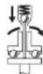
BnHTOBepHTHe HMaT npEkbcsBcEeHNHtEn, OTdJIaB 3aBNCIMOCOT YcTaHOBEHHBbP TMA Momet, KOITMOKe Da bdepeyIpaH B NocOeHHN DnaHa3OH. ToI ce 3aJeCTBa, KOrATo 6bDe DOCTHRHAT HAcTPOEH HbPTAQU MO
MEHT.
Yka3aHHe:KoraTo 3axpaHBe BHTOBepTa c aadantep 3a HanpeXeHne, npBO Tp6Ba Da BKIOUHTe TKOHN3PpABNTen. 3a BKNIOuBaHe Ha eIeKtpOnHCTpyMeHTa HATNCHE Te NyckoBn npEkbCBAu (6)doynop.
EneKtpoHnCTpyMeHTbCE H3KJIIOUyBa aBtOMaTHUHO,Korato 6bIe IOCTHrHaT IpeDbaPHTeHNo HaCTpoEHrT BbPTA M0 MeHT.
Pnp npexkdeBpeMeHNO OTnycKaHe Ha nycOBn npKbcbu (6) He ce doCTHa npedBaHTeHNo 3aJaEHHBbPTaMOMeHt.
Yka3aHn 3pa60Ta
PpeHn da H3BbpuBaTe KaKBHTo n da e DeHocTH no enektponHcTpymenta (Hanp. TexHnecko 6cbnyKbaHe, CmHa Ha pa60THn HcHcTpyment nT.H.), KORATO TpaHCnOpTPaTE HnCbXpaHbATE, DEMOHTpAaTe aKymyNaTOPHa 6atePN. CbIeCTByBa OnaCHOCT OT Ha paHbAhe npn 3aJeCTBaHe Ha NyCKOBn PpeKbcBaN No HEBHMaHHe.
IocTbAHTe eNEKTPoHnCTpyMeHa hTaBaTa HnHTa/raKaTcamaKO KarOte eN3KnIOueH. BpTAAHT ce pa60TeH INCHTpMeHT MoKe Da Ce N3MeTHe.
PerynnpaHe Ha BbPTaunMmOENT (Bx. H-1)
BbPTAINMOMENT3aBCHOTPpeBaHHTeHHTOHaTtAHAHe HnpyKHHATAHnpeKcbCBAUNs CbeHNHTEN.PpeKcbAunHrCTBe3aEnCTBaPnDcTnHaHa3aJaEHnBbPTAUMoHNTKaKTOpN BbPTHeHaJACHO,TAKaNpN BbPTHeHaJIBO.
3a HacTpoBbAe Ha JxenaHn BbPTaI MmEHT N3N03BaIte CaMO BKIOUcEHn BOKOMNKeKTOKaTa CNeuaHn3npaH HnCTpyMeHT (21).
-Ппсмсгетeпьзraчa(10)Ha eNeKtpOnHcTpymeHTaДOK-paHа3a.
BkapaTe HnCTpyMeHTa 3apeyInpaHe (21) B nTaPoHHKa (8) Hro 3aBbpte6abHO.
-Korato npes 0TBopa B Kopnyca Ce BnHm MaIka BnBb6HaTHHa (perynipauaa 7aib6a (22) B CbeHNHTeR, BKapainTe B He HNCTpyMeHTa 3a perynipae (21) n ro 3aBbpte-Te.
3aBbPTaHe NO NOCOKa HA yacOBHnKoBaTa CTpeNkA BOIN DO yBENuBaHa He BbPTaIIMaMOnEHT, 3aBbPTaHe OpaTHO Ha yacOBHnKoBaTa CTpeNkA -DO HAmJIraBaHe.
-ⅢaIeHHTpyMeHa 3a peryInpaHe (21).PpeMeCTe TnB3ra4a (10)OTHOBO HApPeI,3a Da nppeIpa3te CbeHNHTeIaOT 3aMbpcBaHe.
Yka3aHHe: Heo6xOHNMMrBbPTIcMOMeHT3aBnCtOT BnDa HbNHTOBOTcBeINHEHHeNcE ONpeDgHaH-ToUHOype3 H3np6BaHe Ha npakTHKa. PpOBepTe np6Ho 3aBnTOTO Cbe- DnHEHne C dHnAMOMeTpueH KJIou.
PerynpaTe BpTaunH MOMENTcMoB nocouHen Hnana3OH Ha MoUHocT Ta, Tb KaTo B npTHBeH cnyaH N3KNIOVAaHT CbeHHTe He Ce 3aDeIcTBA.
06o3HaayBaHe Ha HAcTpoEHnBbptA MomeHT
3a 0603HaayabaHe Ha CnEuaHIO HAcTpoEH BbPTaIIM MoMeHTM MoKeTe Da 3aMeHHTe MapKHPoBbUHHI PpbCTeH (7)C TaKbB C Dpy UTBHT.
HanpHmep aKo n3nOJ3BaTe qAcT oBnHTOBeptTe EXACT C BbPTaU MOMENT 4,5 Nm, MoKTe da NM IOCTaBte 3a 0603HaayabaHe UepBeHN MapKnpoBbUnn PbcTeHN. Ako n3nOJ3BaTe dpyrBn BnHTOBeptExACT 3a npytn MOThaKNH DeHoc
TH, INH KONTO CE H3N03Ba BbPTAù MOMENT 7,5 Nm, MOXeTe Da NOCTaBHTe 3a 06O3HaUaBAHe Ha TO3N BbPTAù MOMENT MapKINPOBbUeH NpBCTeH C Dpy TCBT (YepeH, CIn, ZENEH INN XbTT).MapKINPOBbUHNTe NpBCTeH C pa3IuHc UCBT Ca INPeH3aHuEH CAMo Da CNyKaT KAtO yNeCHEHn 3a MOHTbOpHTe, 3a Da ce pa3I03HaBa No-LECHO KaKbB BbPTAù MOMENT e YCTaHOBeH HA CbOTBeTHNA ENEKTPOHNCTPymeHT.
3a nBaxdahe Ha MapKnipOBbUHHn npbcteH (7) n3noJI3BaI Te TbHka OTBepTka, nnakna HnDpyr noo6en HHCTpyMeHT.
BnHaHn 3n0n3BaIte eneKtpOnHCTpymEtHa C nocTaBeH mapKnpoBbueH npbCTeH, 3a Da 6bJe 3aunTeH Kopnyca O T npax H 3AmbpcBaHe.
CBeToIDNoDHH HNIMKaTOpH

CBeToHnO3aCTeNEHTHa3apeDeHoCT Ha akymyIaTOphNAt6aTePn
Ako e heo6xOIMO 3apejkahe Ha akymynaTOpHata 6aTepeHra (5), 3eHeHnAT CBeToNDoeH2) 3anOuBa da Mna H ce CyBa 3ByKOB CnHAn.
CneToBaCaBb3MOxHNOoce caMo6 Do 83aBnHTBaHna.
Ako CBetOnIOHOCTCBETHE C UepBeHa CBETNIHa, KanaUHTeTb Ha 6aTepeHra He NOCTHra 3a OoIE eNHO 3aBnBaHe /pa3BnBaHe HIN ENEKTPOHNCPTPymeHbTe 6bnI pTeOBapeH. CneT ToBa ENEKTPOHNCPTPymeHbTe H MoKe Da 6bDe BKNIOueH NOBEe. BLOKIPOBkATA 3a BKNIOuBaHe OCTaBA AKTNBHa, DOKATO AkyMynaTOPHa7a BATEpHHe 6bDe N3BaDEHa OT ENEKTPOHNCPTPymeHa H Hero He 6bDe NoCTaBeHa HOBA 3apeDHa AkyMynaTOPHa 6aTepeHra.
Ako paobotte c aanTep 3a HanpejekHe, CBetBaHTo Ha CBeTOIOHN HNINKAtop (2) C cepBHeA CBeTNHa e yKa3aHne 3a npTeOBapBaHe.
CbueCTBHeo CbKpatoHO BpeMe 3a pa6ota Ha eneKtponHCTpyMeHTa CneI 3apeJdaHe Ha akyMnyatopHa 6atePnnoKa3Ba, ye 6atePnraT e H3xa6eHa n Tpr6Ba da 6bde 3ameneHa. N3xBpnaHTo Ha cTapaA akyMnyatopHa 6atePnTpr6Ba Da ce H3Bpwn Cb6pa3HO BaHHnHte Pa3npoe6n.

CbeToHOD3aBbBaHe
PnDocTnHaHe Ha npeBapntHoYoCTaHOBeHn BbptTu MOMeHT N3KJIIOUBAuHT CbeHNHTe Ce 3aEnCTBa.CBetoNIOHNr INHdkaTop
(1)CBETBa3eNeHo.
Ako npedbapntenHO yctahOBeHNr BbPTaM MOMENT He 6bJe DOCTHnAT, CBETOHOJNHT HnHKaTOp (1) CBeTa YepBeHo, HcyeBa 3ByKOB CNrHan. IpoueCt Ha 3aBnBaHe Tp8Ba Da ce NOBtOPI.
3aunTaOTNOBTOpeHne
Korato B npoeca Ha 3aBnBaHe N3KIIuOyBaUHr TcbeHNHTen ce 3aEeCTBa, eNEKtpoDnBnraTeAerTce H3KIOUByA. NobTOPOBkUOBA He Bb3MOxHO eBa CneI INTEpBaI OT, 0,7 cekyn. TaKa Ce H36raBa PpeHabBaHTo Ha Beue 3aTeHaTH BuHTOBn CbeINHeHHa.
PoiDlbpxKaHe n cepBn3
Iopdbpxkane nouhcTbahe
PpeHda H3BpWBate KaKBHTO H da e DeHIOCTH NO eNEKTPOHHCPTyMeHTA (HAnp. TexHnuecko 06CnykBa
He,CMHa Ha pa6oTHH NHCtpyMeHT H.T.H.),KORATo TpAHCnOpTnPaTe HIN CbXpaHBAte,DEMOHTnpaTe akymaTopHata 6aTePn. CbIeCTByBa ONaCHOCT OT Ha- pAHBaHe Pn3aEiCTBaHe Ha NyCKOBn IpeKbCBaY NO HEBHMaHHe.
3a da pa6oHTe KaueCTBHeO 6e30nacHO, noDbPkaIte enEeKtpOnHcTpyMeHTa N BeHTnlaucnoHHTe MyOTBOpN uCTH.
Cma3BaHe ha eneKtpOnHcTpymeHa

Cma30uHO BeuecTBo:
CneuHaHa peyKtopHa rpec (225 ml)
ApTnKyuEn Hoomep 3605430009
MolnKoTHa rpec
Дигагенно MacNo SAE 10/SAE 20
- CneI nbpBnte 150 pa60THn yaca nouHcTepeyKTopa c MEK pa3TBOPHTe. Cna3BaIte yka3aHnIa THa npOn3BOUH TeI Ha pa3TBOPHTe IOTHOCHo HauHnMy Ha n3IOn3BaHe HxHBpIHe. CneI TOBa CMAKeTe peyKTopa Cbc CneuaHATA CMA3Ka Ha BoW 3a peyKTopn. CneI TOBa NOBtapRnTe Ta3n IpOeDpya Ha BCEkn 300 pa60THn Ya ca.
- CmaKeTe NoBnKHHte YacTHa H3KNIOUBaUNcBeHNHInTe cIe1 100000 3aBnBaHnC HAKONKO KaKN DIBrAteHo MacNo SAE 10/SAE 20. Korato Cma3BaTe peyKTopo, BnHaRn IpOBeRbAte CTeneHTa My Ha N3HOcBAhe, 3a da HMaTe yBpeHocT, Ye NOBTOpeMOCTTa H TOHOCTTa HMa Da 6bDat HapuWeHn. HApKaY OTHOBO TpRA6Ba Da 6bJe HAcTPOeH BbPTraNt MOMeHT, PnI KOITo CbeENHtEnr T3KJIIOUBA.
OCTABYIe NOIDbPkaHTo H pEmoHTHnTe DeHocTH da ce N3BbPWBat cmo OT KBaHHNcHpaHH texHHu. Taka ce rapaHTnpa 3ana3BaHe Ha 6e3onacHocTt Ha eneKtpoHHCTpyMeHTa.
Ta3n DeiHocMT MoKe Da 6bJe H3NbJIHeHa 6bp3o N KaueCTBeHO BOTOp3nupaCepBn3a HnCTpyMeHTn Ha BoW.
13XbPJIte CMA3OuHH NIOUHCTBaUN npenapatn no HaHH, KOTo He 3aMbpCBA OKoHnTa cpea. Cna3- BaIte 3aKOHOBnPe pa3npope6n.
KnentcKa cnx6a H KOHCyntaun OTHOCH ynotpe6ata
CepBn3bI ue OTROBOpn Ha Bbnpocnte Bn OTHOCHOpeMOHTn I noDpBkKa Ha 3akynenHr OBa npOyK, KaKTo HOTHO pe3epBHN qactN. POKOMNoEHTH NyeptExn HnΦopMa-ua 3a pe3epBnHTe qactn ue OKpnEte Ha: www.bosch
pt.com
EkntnoKocyntaOnOTHOCNoYnOtp6aTaHaBoschue Bn NOMORHe C yIOBOJCTBHe npn Bbnpocn 3a HauHtene npoDyKTn nTexHNTe akcecoapn.
MOn, npBvbpocn H npnpOpbUbaHe Ha pe3epBHN qactH BnHaH nocOuBaTe 10-uaPpeHH KaTANOKeH HOMep, n3nnCah Ha Tabekkata Ha ypea.
Блгария
Robert Bosch SRL
Service scule electrice
Strada Horia Macelariu Nr. 30-34, sector 1
013937 Bucuresti, Romania
TeN.: +359(0)700 13667 (Быларскн)
c: + 40212331313
Email: BoschServiceCenterBG@ro.bosch.com
www.bosch-pt.com/bg/bg/
Бракуван

EeKTPoHnHcTpymEnHtpeHHN DOnbHNHTenHtne npncoc6neHnTpaBa da 6baatnpedabaHn3a onon3oBopra
BaHe Ha CbDpJxuNTCe B TEx CypOBHH.

He n3xBbPnIte eEnkTPOHCTpymeHTn akyMynatopHN nn 6nKHOBeH 6aTePN np 6nTOBHTe OTnabu!
Cama 3a cTpaHH ot EC:
CbINaCHO eBpOneKcA npeKTHBa 2012/19/EC eneKtpoypeHTE, KOHTo HE MOrAT da CE non3BAT NOBce, a CbINaCHO eBpOneCKa npeKTHBa 2006/66/EO nobpeHn Hn H3xa6beHn ObHKHOBEHn Hn akymynatOPHN BATEPN Tp8BA da Ce cb6HpATn PpeDa 3a ONON3OTBOPBaHe Ha CbDbpxKaUHtE ce B TAX CypOBHHN.
AkymnaTOPH HnO6HKHOBeHH 6aTePHN:
Ni-Cd: HnKeJ-KaDMn
BHHMaHHe: Te3n aKymyNaTOpHN 6aTePnN cbDbPjXaT KaD Mnn, KOTo E CmHNO OTOPOBeH TeXbK MetAn.
Ni-MH: HnKeJ-MeTaJIxNДpIa
MaKeDoHcKn
Бe36eHocnHaNoMeHn
OnuTH npdeynpeyBaHa 3a 6e36eHocT a eNeKtpnH anatn
PENEY
PENyBAHe
Ipoountajte rH cHTe 636eHocnnpedynpeyBaHa, nlyctpaunm IcneuФнkaun npinoJoxen co
OBJeKtpnueH anaT. HnprpkyBaHbeto Do cHTe yNaTCTBa npINOKeHH pOJy MoKe Da IOBeE Do CTpyEH yAp, noKap N/nn TeKKn NobpeH.
3auybaTe r6e36eHNOCHNTpeDynpEbyBa H ynaTcBA 3a KopncTebe H 3a BO NHHHa.
POnMOT,eneKtpnueH anat"BO636eHocnHTe
PpeDynpEduBaBa ce OndecyBa Ha eNeKtpnHn anapatn wTO
KOpHCTaT CTpyja (Ka6eNcKn) HnAnapatn WTo KOpHCTaT 6aTePnn (akymyNatopckn).
Be36eHnoctHa pa6oTHnOtnpocToP
Pa6oTHNOt npocTOp OpOxyBaJTe ro qHcT Hdo6po ocBETnEN. IpeONH Nm TEmHN IpocToHN MoKe Da DOBeaT Do HepeKa.
He pa6oTeTe co eNEKTPnHHTe anaTH Bo EKcNIO3MbHa OKoJIHHa, KaKO Ha npHMeP, BO pNcycTBo HA 3anaIINB TeuHOCTn, rAcOBn HnnpaunHa. ENEKTPnHITe anaTH CO3aBAaAT NCKPN KOHI TO MOKe Da ja Ja 3anaIaT npaHnHaTa nnr fAcOBtE.
Држete Гдеца и пссутнente поалени КддяпсдяпсдяпсдяпсдяпсдяпсдяпсдяпсдяпсдяпсдяпсдяпсдяпсдяпсдяпсдяпсдяпсдяпсдяпсдяпсдяпсдяпсдяпсдяпсдяпсдяпcдяпсдяпсдяпсдяпсдяпсдяпсдяпсдяпсдяпсдяпсдяпсдяпсдяпсдяпсдяпсдяпсдяпсдяпсдяпсдяпсдяпсдяпсдяпсдяпсдяпСdяпсdяпСdяпСdяпСdяпСdяпСdяпСdяпСdяпСdяпСdяпСdяпСdяпСdяпСdяпСdяпСdяпСdяпСdяпСdяпСdяпСdяпСdяпСdяпСdяпСdяпСdяпCdяпCdяпCdяпCdяпCdяпCdяпCdяпCdяпCdяпCdяпCdяпCdяпCdяпCdяпCdяпCdяпCdяпCdяпCdяпCdяпCdяпCdяпCdяпCdяпCdяпСdяпСdяпСdяпCdяпCdяпCdяпCdяпCdяпCdяпCdяпCdяпCdяпCdяпCdяпCdяпCdяпCdяпCdяпCdяпCdяпCd-rayCd-rayCd-rayC
EneKtpnHa 6e36ednoct
PnKnyokot Ha eNektpuHNOt anat mopa da OrodBapa ha npNKnyuHnQata. HnKoraa He ro MeHyBaJte npNKnyoKOT. He KopnCTne npNKnyuHn AanTepn co 3a3emJeHnte eNektpuHn AnaTH. Hen3MeHeNTe npNKnyOuH n COODBeTHNe Tpe npNKlyuHnU RO HAmanyBaat pN3HKOT OD CTpyEH yap.
N36erHybaje TeneceH KOHTKT co 3a3emjeHH NOBpHHK, KAKo Ha npMep, cEKN, paJnatOpn, METAHn Hauu H aadnnu. IocToH 3roJeMeH p3NK Od CTpye H yap aKO BaWTe Teno e 3a3emjHo.
He nH3noxybajte eneKtpnHHTe anaTH Ha doxKn Hn BnaXKnYcNoBn. Ako Bne3e BOda BO eneKtpnHNT aHaT, Ke ce 3rOJEMn pNkOT od CTpyen ydap.
He noctanybaje HecooBetheo Ka6enot. HnKoraw He ro KopnCTe Ta6cebe, Bneuehe nncknyBaBe o ctpyja Ha enektpnuHnot anat. Ka6enot yBaje ro nOdaKe y od oran, macno, octpn NnNn NOBHXHN DeOBn. OwTeTeHN nnn 3aJIeTKaHH Ka6nI rO 3rOJeMyBaAT pN3NKOT od cTpyeh ynap.
Pn pa6oTa co eNEKtpuH eHa otBopeHo, KopHeTe npOOnJxH KabEn COOBETe 3a HAdBoPeWHa yNoTpe6a. KopHeTeHO Ha KaBen COOBETe 3a HAdBoPeWHa yNoTpe6a ro HaMaNyBa PnIKOT OCTpyEN yAp.
Ako Mopa da pa6oHTe co eNeKtpueh anat Ha BlaXHO mecto, KopHCTe 3aHTEN ypei 3a nfepeHuaHa ctpya (RCD). KopHCTeHeTo HA RCD ro HamaIyBa pN3NKOT od cTpyeH yap.
JIuHa 6e36eHnOCT
EHNTe BHHMaTeHNN, BHMMaBJte KAKo pa60ntHe pa60Te pa3ymHo co eNEKtpnueH anat. He KOPHCTe ENEKTPnueH anat aKO cTE yMOpH HIN NIOd JeCTBO Ha IPOrH, ANKOXO HIN NEKOBH. EEN MOMENT HA HEBHMaHne IDOeKa pa60NTe CO eNEKTPnUHTe anat M0Ke Da IOBede Do cepno3Ha IINuHa NOBpeJa.
KopncTe TnHua 3auTHHa onpema.Cekoraw Hocete 3auHTa 3oyn. 3auTHHaT aONPema, KaKO Ha np.. Macka 3a npaHna, 6e36eHNCH YeBn KOnuTo He ce IINrTaAT, JIeM HnN 3auHTa 3a yUn, KOUTo Ce KopnCTa
3a COOBeTHN YCNOB,Ke DOBeDaT Do HaMaNyBaHe HaJIuHH NOBpeH.
Cnpeute HeHamepho AKTHBnpaBe. IpOBepete daHn npEKNHyBaOT e NCKnyeH nped Da ro BKnyuHTe BO ctpya n/nn co ceTOT ha 6ateHN, nped da ro 3emete HnHOCTe anatot. HocHe Ha enkTPnuHnte anaTn co npCTOT nO3nIOHpAH Ha npEKNHyBaOT nBklyuBaBe BO ctpya Ha enkTPnuHnte anaTn uJwTo npEKNHyBaOT e BknyeH, MOKe Da npEn3BnKa HecpeKa.
OTcpanheKaKOB 6nlo Knyu3a perynpahe Hnn φpaunyckn Knyu nped da rO BknyuHte eneKtpuHnot anat. Phaunyckn Knyu nn Knyu npkaueh 3a potnpaKnOt den Ha eNeKtpuHnoT anat Moke da doBeede do nnuHa nobpeda.
He r n peneekopybaje orpanuhybaata. Noctojano odpxybaje cooDBetna noox6a npamhotexka. Oba OBO3MOxkyBa NOO6pa KOHTpOHa eNEKTPnHnot anat BO HENpeBnDnHBnCITyaun.
O6neueTe ce cooDBetHo. He Hocete uHPOka oBNeKa n hAKHT. Kocata n anuTuTa Tpe6a da 6nDat noDaneky od noDBHXHNTe denOBn. UpOKATA oBNeKa, HAKHTOT nnIIOJrata KOCA MOKe Da ce 3aKaayat 3a NOBHXHNTe denOBn.
AkoceKOpHCTaTIOBp3AnHypeHn3aBaHebe npaHHHaNcoBpaHBePpeMTe,poBepTe daHc ce npabHHoNOBp3AHN KOpHCTeHH. CoBpaHeto npaHHaMOKeJaHnHaMaHnOnaCHOCTte PpeHN3BnKaHnOJ Hea.
He 03BOnyBaJte NCKyCTBOTe CTKHATO co yecta ynoTpe6Ha anaHTe Da Be HnpaBN CNOKOJIHN da Hn HrhopnPate 6e36eHOCHTe PnHcHnN PnHNBHO To KopncTeHe. HeBHnMaTeIHO DnKHeBe MoKe Da npEn3BnKa cepNo3Ha NoBpeDa BO den Od ceKyHda.
YnTope6a HyBaHbe Ha eNeKtpuHHTe anatH
He ro npeonTobaybajte enektpnHnot anat. KopncTeTe cooBBeTe enektpnH anat 3a HameHaTa. Co cooDbetNt enektpnH anat noD6po, no6e36eHno n no6p30 ke ja hBpuNTe paOta 3a Koja e HameHet.
He Kophctete enektpnueh anat ako He mokeTe da ro BknyuHTe H NCKyUHTe co NOMOHa npeKNHyBaOT. Ceko jeneKtpnuH anat kojtTo He moKe Da ce KOHTpOInpa CO npeKNHyBaOT e OnaceH Mopa Da ce nonpaBN.
McknyeTe ro enektpnHnot anat od ctpya n/nnn 3BaDeTe ro ceTof Ha 6aTePN, Ako ce BaN, nped da npaBHe HeKaBn PpHaRoDyBaBa, MeHyBaTe DOONHTenHa ONPema Hnro CKnaDnpate enektpnHnot anat. Co OBne IpeBeHTNBn 6e6eHNoCHm MepKn Ce HamaNyBa pN3NKOT od CnyajHO BknyuBaHe Ha enektpnHnot anat.
Uybajte rne eneKtpnHHTe anatn noanaleky oddoaht Ha deca n He do3BonyBaJTe nnata KOHpe pakybane co e neKTPnHHot anat HnHe ce 3ano3Haehn CO OBA ynatCTBO da pa6oTaT co hctHOT. EneKtpnHHTe anatn ce onacn BO paueTe Ha Heo6yuHn Kopncnun.
OdpjxBaIbe Ha eEeKtpHn H aIaTH NdoONHHTeHa onpema.IpoBepTe ro nopamHyBaIbeTo Hnn npucpcTyBaIbe Ha noDBHXHTE DeIOBN, cnoJOT Ha IeIOBHTe HcTHe dpyrN yCNOB hTO MOKe HeaTHBHO Da BnJaat Bp3 cyHKUHOpHaBeTo Ha eEeKtpHnHOT anat. Ako e OoTeteh, OdheceTe ro eEeKTPHnHOT anat Ha nonpaBkA ppeI da Ro KOpCTHe.Mhory HecpeK ce nped3BkAHH 3apaHn HecooDbETHO oDpXyBaIbe Ha eEeKtpHnHte aIaTH.
Octpete Hnctete rnaatacehe. CooBETHO ODPKByaHHTe HbNHa aIaNtTe 3a ceHe nOMaIKy Ce BNTKaat I NOECHO CE KOHTpOINpaAT.
EneKtpnHnO anat, dononHnTeHnHaT Onpema, dnoBHTe Hp.KOpNCTe Tn BO corNaCHOcT CO OBA ynatCTBO,BHMabajte Ha paBOTHnTE YCNOBn H paotata koja ja Bpnte. KopnCTeHeTo Ha eNEKtpnHnO anat 3a npTu HAmEH MoKeJa DOBeDe Do ONaCHN CNTyaun.
PaKHTe H NOBpHHNHTe 3a dpXHe ODPxYBaJte H cyBN, NCHTH HEN3MaCTEH. PaKHTe H NOBpHHNHTe 3a dpXHe WTO CE IIN3raaT He OBO3MOxyBaat 6e36eHnO paKyBaHe H KOHTP0la Ha anatot BO HnpeBnINHBn CNTyaun.
YnOTope6aHyyBaHeHaBaTePncKnAnat
Nonhe ja 6atepnjata cmo co nonnau Habeen od npon3bOHTENOT. NOnHau KOJwTO e COoDBTeH 3a eHEn TnCt Ha 6atePN MOKe da npednBnKa OAnCHOCT O nokap aKc ce KopnCTn 3a dpyr CET Ha 6atePN.
EneKtpnHHe anaTH KopHCTe Tc mo Co CneuJahno HameHEn CeTOBn Ha 6aTePH. KopHCTeHbTo Ha npyH n ceTOBn Ha 6aTePHN MoKe da npedn3BnKa onaHocT od NobpeHa nn Noxkap.
Kora he ro Kopnctte cetot ha 6aepnn, yybaje ro noaneky od npyrn MetaHn npedmetn, kao Ha np., cnojybankn, MOHTN, KnyueBn, wajKN, 3abptKn Hnnpyrn NOMANn MeaHn npedmetn WTo MoXe da npedn3bHKaAT Cnoj od eEe Do pyr n3bOp. Kpaok cnoj ha 6aepncnte n3bOpn moXe da npedn3bKa nropeHNu nn nokap.
PnHnpeBnDEnOkONHocTn,TeuHOCTMoKe Da HCTeue Od 6atepNjata;N36erHyBaJte KOHTa. PnCnyaeh Donnp, N3MnJte Ce Co Mna3 Boda.AKo TeuHOCTa BNe3e Bo OuyHe, No6apajte DoonOHNTenHa MeHNCHKa NOMo. TeuHOCT nCTeueHa od 6atepNjata MOKe Da IpeDn3BnKa nputaJna nn N3ropeHnU.
He ynotpe6ybajte cet Ha 6atepHH HnH anat wto e OWTETEH NnN H3MeHET. OWTETEH NnN H3MeHETn 6atepHH MoKe da pearnpaat HnpeDbNnBO n da npedn3BnKaat noxkap, eknno3nJa nnn OnaCHOCT od NOBpeDa.
He ro n3noxybaje cetot Ha 6atepnn nn anatot Ha oran Hnn BncoKa Tempepatya. N3noxyBaheTo Ha oran HnHa Tempepatya Nobcoka on 130^ MoKe da npedn3Bnka ekcnno3na.
CnepeTe H cHTe ynatCTBa 3a nonHebe H He ro nonHete ceTOT Ha 6aTePHn Hn anaTOT HaBOp oD
TeMnepaTyPhHOT ONce HabeDen BO yNaTcBtA. HenpaHHoTo nonHeIe nn Ha TmpePaTypa HApBOp od HabeEHNOt ONcer MoKe da ja oWTeN batepnjata n da ja 3rOlemn OnaCHOCTa OD NOxap.
CepBnCnpahe
EneKtpnHnot anat cepBncpajte ro kaj KBaHnKByBaHO nue Koe KopnCTn cmo HeTHnPe3epBHH denOBn. Co OBA ce OBO3MOxyBa 6e36eHOn OdpKyBaBe Ha eneKtpnHnot anat.
HnKoraw He nonpaBajte oWTeHen CeTOBn Ha 6aTeHH. IOnpaBkata Ha ceTOBn Ha 6aTeHH TpeBa da ja BpHc camo npOH3BOIDHTeNt Hn OBnACTeH CepBHC.
Be36eHocn HAnomeHn 3a ODbpyBaun
Држete ro ekeTpHnOt anat 3a n30nnpaHaT aOBpHHa doEka ceyeTe, 3a npuBpctyBaOT da He dojde BO KOHTaKT CO cKpHeHa Xua. Ako npuCBPCTyBaHTe DoJaT BO DOINP co ,Xnua nOd HanoH MOKe Da rN N3NOxAT MetaHHTe DeNoBn Ha eKeTprHnOT aNat ,noD HANOH" n Oepatopot Moke da no6ne cTpyeh ynap.
KopCTe CoOdBETH ypeH 3a npe6apyBahe, 3a da H npohajTe cKpHHeTE eEKeTPnHn Ka6Hnn KOHCytnpajTe co NOKANHO TpeTnpjAte 3a ChabyaBe co eKeTPnHa eHepnJa. KOHTAKTOT CO enektpnuHn Ka6Hm MoKe Da IOBede Do NOxap H CTpyH yap. OWTetyBaHTo Ha racoBOOT MOKe Da IOBede DO EKcNIO3na. HabneryBaHTo BO BDOBOHN CEKBn PpeDn3BNkyBa OWTeYBaHe.
Ubpcto dpxkete ro enektpnHnoT anapat. Pn 3aucbpcTyBaHe n ODBpTyBaHe Ha npapOBn MOKe da HacTaHaT KpaTKOpJHn BcOKn peaKTHBn MOMHTN.
3aucpcte ro napyeTo wTo ce 6pa6oTyBa. DOKONky ro 3aucpcnte co ype3 3aTeHyBaBe HnH MeHReMe, ToraawnapyeTo wTo ce 6pa6oTyBa ce npKn noOpBpTo OTKOnky co Baata paka.
Pouekajte dokeka enektpnHnot anat cocema npekne co pa6ota, ped da ro tprhe Hactpna. Anatot wto ce BMETHyBa moKe da ce bloKnpa n da DOBeDe Do rHybe KOHTpona Hnd ypeDTo.
PnOwTeTyBaBe HEnpOnnHcHa yNtpe6a Ha 6atepnjata MoKe Da n3ne3e naPea. Batepnjata MoKe Da ce 3anannnna Ea EKcnnoHpA. BHece TcBex BO3dyx NdoKoIky HMa NobpeHn OndecTe Hn HaNekap. PapeTa MoKe Da rHaDpa3HN dHInHte NaHHTa.
He ja otbopajte 6atepnjata. Noctoh onacnoct od KpaTOK cnoj.
BaTepnjata MoKe Da ce oWtETn Oocptne npedmetn KaKo Ha np. KInHn HnOdBpyBaHn Co HnBopeuHO BnJahne. MoKe Da doJe De OBAtpweHn KpaTOK Cnoj n BaTepnjata MoKe Da ce 3aapani, da nyTuHn qad, da ekcnlonpa Hn da ce nperepee.
Kophtete ja 6aTepehjata cmo BO npOn3BODn O npOn3BODHTeOT. Cmo Ha ToJ HauHH 6aTepeHjata Ke ce 3aHTTN OD onacHO npeontOBapyBaHe.
3aHTe ja 6aTeepjata OJ ToNNHa, Ha np. OJ Donroptajno H3NoxyBaHe Ha COHueBn 3paun, oran, Boda n Bnara. NaKy, nocton ONaCHOCT OJ EKcNIO3NJa.
Дokonky ce 6nOKnpa anatot wTo ce BMeTHyBa, BeHaH uKcNpyeTe ro eNEKtpuHnOt anatot. BHeTe npTeNa3HNB CO BnCOKHTe peakncKn MOMeTH, wTo MoKe Da npeDn3BnKaAT NOpateH yAp. AnaTOT wTo ce BMETHyBa ce 6nOKnpa, aKO eNEKtpuHnOT anaTce npeoITOBapu Hn Ce HabaH KOH dIOT wTo ce o6paobTyBa.
PENEY-PENyBAHe
PpTa wTo HactaHyBa npn mnpraabe,ceebe,6pycebe, dynpebe nCNHn DejHocTH MOKe
daHMa KaHeporeHo, TepaToreHo HnMyTareHo DejCTBO.
Hekon od OBHe MaTePNn CoDPKAnH BO npaBt Ce: ONoBO Bo 60H n NaKOBu WTO CoDPKAt ONoBO; KpncTaeH CNmUyM Bo Urnn, ZemEn H dpyn Suapckn pa60n; apceH XpOMat BO xEMNCKn TpeHpaHO dpBO. P3HKOT od 3a6OlyBaBe 3aBnCH oD ToA KOkny YecTo Cte N3noKeHN Ha OBHe cynCTaHc. 3a da ja HamaHte OnacHocta, Tpe6a da pa6oHTe cmo BO do6po npOBetpeH npocToPn co COoDBETHa 3aWHTHa ONpema (Ha np. Co cneunJalHo KOHCTpypanH ypeH 3aWHTTa pRn DnIWebe, KOH n fHITPPaAT H hajCHTHe YeCTNuKN Ipab).
N36erHyBaJte cnyajHo BknyyBaBe. Ochnypete ce deKa npeknHyBaOT 3a BknyyBaBe/ncknyyBaBe e BO ncknyeHa no3nju, nped da CTabHe 6atepnja. HocbeTo Ha eneKtpuHnot anat Co BaHnot npct Ha npeknHyBaOT 3a BknyyBaBe/ncknyyBaBe nn CTabaHe Ha 6atepnjata Bo BknyeH eneKtpuH anat MOKe Da DoBede Do HepeKeH cnyaj.
KopHCTe cAmo HcnpaBHH, Hen3a6eHH anatn 3a BMeTHyBaBe. DepeKTHHTe anatn 3a BMeTHyBaBe MoKe Ha np. da ce CKpWAT n da IOBeJat Do NOBpeHn MaTepnjahnH WtETn.
PnCTaBaBeToHa anatOT 3a BMETHyBaHe, BHIMAbaje Ha Toa Toj Da JIeKIN CBpCTo BO npHpaTOT 3a anar.10OKONky aIaNtOT 3a BMETHyBaHe He e cBpCTO NOBp3AH CO pNpTaT OHa anAT, MoKe da Ce onaabAn da ce cnuyn da He MOKe da CE KOHTponIPA.
6Hnde npetna3nBn npn 3aBpyBaBe Ha donr n 3aBPTK, 6HdejKn NocToN onaChOcT OIN3HyBaBe, BO 3aBnCHOCt O BnD0rHa 3aBpTKaTa H KopHCTeHNOT aNat 3aBMETHyBaBe. YecToNaT, dONrTe 3aBPTKn He MoKe Da ce KOHTponpaat TOnkY Do6po H NocToN onaChOcT da Ce cIn3Hat npn 3aBpyBaBeTo N da CE NOBpeNiTe.
BHHMaBajTe Ha NoCTaBeHnO TnpBeu Ha BpTeHe, nped Da Ro BKnyHTe enEeKTPnHnO t anat. DOKoIky, Ha npMep, cakTe Da OJbPTHTe 3aBPtKa, a npaBeouT Ha BpTeHe e NocTaBeH 3a 3aBPyBaHc Ha 3aBPtKaTa, MoKe Da JoJe Do CInHO HeKOHTpOnIPAHO DBHXKeHe Ha eNEKTPnHnO t anAT.
He ro Kopnctete enektpnHnot anat kako dynyanka. EneKTPnHTe anaTH co eHa cnojka 3a ncknyuBahe He ce noroDHN 3a DnyuHe. Cnojkata Moke aBtOMaTcKn H 6e3 npdynpdyBaBe da Ce ncknyu.
Onnc Ha npoH3BODOTn nepΦopMaHCNTe

Ipoountajte rH CHTe 6e36eHNOCH HANOMEH n yNaTCTBa. IpeuKHTe HaCTaHaT Kako pe3yNTa OD HeNPdRpKyBaHe DO 6e36eHNOCHHTe HANOMEH n yNaTCTBa MOKe da npednBnKaateneKTPnuEYap, noXap n/nn
Teškni nobpevi.
BHHMaBaJTe Ha cIHKnTe BO npeHnO T dE H a yNaTcBTo 3a KOpNCteHe.
YnoTpe6a co cooDbetHa HameHa
EneKtpnHNOI anaTe HameHET 3a 3aBpyBaBe n ONaabByBaHe Ha 3aBPTKN, HABPTKN I npTu CBp3HN eNeMeHTn CO HAOBJ BO DaJeHNTe rpaHnHa dHMeHn N MOKHOCT.
EneKtpnHnot anat He norOeH da ce KopncTn kaKo dnyaik; 3a Da n36BerHeTe NnHn Nobpei MATEpnaHn tETn, HNKoRaH He Tpe6a Da ro Kopncnte enektpnHnot anat co NcKnuyHa cnojka 3a Dnyuehe.
Hnyctpaunja Ha KOMnOHeHTN
HymepnpaheTo Ha cInKHTe CO KOMnoHeHTn Ce OndecyBaHa npka30 Ha eNktpuHnot anat Ha rpaqukata cTpaHua.
(1) LED-πρικα3 Ha 3aBpTyBaHbTe Ho cNojHnUte
(2) LED-npka3 Ha HanoHHeToCTa Ha 6aTepejna
(3) IpeknHyBaay 3a MeHyBaHe Ha npabeoTo Ha BpTeHb
(4) Konue 3a OTKlyuYBaHbHe Ha 6aTepeNjaA
(5) BaTePnJa co APT-npKnyueH KOHTaKT
(6) IpeKHyBaay3a BknyyBaHbE/INckNyyBaHbE
(7) Ppcteh 3a obenexyBahe
(8)PnpaTHaanatOT
(9) Anat 3a BMETHyBaHBe (Ha np. 6ntOBn 3a OdBpTyBaU)
(10) H3rau 3a H36op Ha BpTeXeH MOMENT
(11)ПОннayA)
(12) Мрженин рпклунчok
(13) 3eENLED-πpɪkəaHa nɒlɪhaʊT
(14) LpBHeN LED-πρικα3 Ha nonHauOτ
(15) PnKnyHa yaupa 3a cTpyeH aanTepe Ha 4EXACT
(16) D-Sub-npknlyuok
(17) 3aBPTKn Ha D-Sub-npknnyoKoT
(18) CtrpyeH aanTep
(19)БрзоэТerHyBaKa rnaBaA
(20) Pa6oTHO CBETNO
(21) AlaT3a noDecyBaHe
(22)Плоча за noidecyBahe
(23) PaçaKa (nɔJInpHa nOBpHnHa ha paKaTAta)
A) NmyctpnpaHATA HnONnHaa ONpema He eno CTaNADnHOT O6e Ha CNOpaka. LcnOchTa ONpema MoKe daJaHaJeTe Bo HauWata Iporpama 3a ONpema.
2001MaKeJOncKn
Texnukn noaToun
BkyHHTe BpeDnOCTHa Bn6paun a, (BeKTopcN 36np Ha TpH HAcOK) H HeCNpyPHoCT K daEN CE BO corNaCHOCT CO EN 62841-2-2:3aBpTyBaHe: a_h < 2,5m / s^2,K = 1,5m / s^2
HnBoto Ha Bn6paunn HabeJeHO BO Obne yNaTcBa n BpeDnOCTa Ha EMncjata Ha 6yuaba Ce N3mepEn Cnpoed MePHN NOCTaKN H MOkat Da ce KOpNCtAT 3a CnpoEd6a Mery eNEKTPuHN anAtn. IcTo Taka MoKe Da ce npilarOdn 3a npedBpemeHa PpoeHa Ha HnBOTO Ha Bn6paunn H emncjata Ha 6yuaba.
HabeJeHOTo HnBO Ha Bn6paunn H BpeHocTa Ha emncjata Ha 6yaba TnpctaByaat rnaBHnte npImEHn Ha eNEKtpuHnot anat. DOKOLKY eNEKTPuHnot aIat ce KOpHCTn 3a dpyTN npIMEHn, aIaNtOT wTO CE BMETHyBa OTCTanyBa OD HopMTte HnH HeIOBONHO ce ODPKByBa, HNBOTO Ha Bn6paunn H BpeHocTa Ha emncjata Ha 6yuaBa MoKAT da OTCTanyBaT. Oba MoKe 3NaHTeHNO Da ro 3rOJIeMHn HNBOTO Ha Bn6paunn H emncjata Ha 6yuaBA Bo zENoKynHnot nepnoHa pa6oTeHe.
3a npeu3no O npdeyBahe Ha NHBOTo Ha B6paunn emncjata Ha 6yuba, Tpe6a da ce 3eme npeBnD nepnoDT BO KOJ ypeDoT e NCKnyeH nn pa60t, a HE BO MOMHTO Kora e BO ynotpe6a. Oba moke 3aunTeHNO da ro HamaHn HBOTO Ha B6paunn Emncjata Ha 6yaba Bo 9eNoKynHNot nepnoHa pa6oTeBe.
YbPdTe rDOnOpHNHeTHeMeRKn 3a 6e36eHocT 3aHTHa KOpNCnKOT O BnJaHHeTo O BnBpaunHe, KaO Ha np.: OpJxByBaBe Ha eNEKTPNHtE aIaN H aIaNtTe 3a BMETHyBaHe, OpJxByBaHe Ha TOnIIHHata Ha INaHKTe, oprAHn3npaBe Ha TeKOT Ha pa6oTa.
MOHTaKa
Ppe6nloKaKbHaHTepBeHcNjaHaeneKTPuHnO nata (Ha np. OpKyBaHe, 3aMeHa Ha aIaTH.) KaKO n pH HerOB TpaHcNoT H cKnJaHa, H3BaTe ja
6aTepeHjata OD Hero. PnH HeBHMaTeHNO PnHTNcKaHb Ha npekHyBaOT 3a BkIyUyBaHe/NCkIyUyBaHe NOCTO ONaCHOCT OJ NOBpeH.
06emHaHcnpopaka
Tun
0602490437/0602490471/0602490447/ 0602490469
Hndyctpcknot 6aTePnCKn ODbpyBaue HCnpaCyBa 6e3 aIaN 3a BMeTHyBaBe, NakyBaHa 6aTePnN, NOHau, perynatop nIaIantep 3a HAnOH. CtpyJHnte aIaIantepn Tpe6a Da ce yNoTpe6yBaat NcknyuHbO 3a npKlyuyBaHe Ha Hndyctpcknte 6aTePnCKn ODbpyBaHn OD Bosch Ha perynatop Ha HAnOH 4EXACT.
Pa6oTHa OKOJIINHa n cKnadnpaIbe

EneKtpnHNoT aIaTe ncknyuNb Ho HameHeT 3a ynotpe6a Bo 3aTbOpEn IpocToPn.
3a 6ecnpekopha pa6ota,do3BOHeHata OKoHa
TempepaTpa Tpe6a Da 6nE nomery -5°C n +50°C (23°F n 122°F) pni Do3Bolna peNaTHBa BlaXHocT ha Bo3dyxOt mey 20 n 95% 6e3 KOHdeH3aunja.
BaTepnjata Tpe6a da ce cyuBa ha Te mtnepaTpy Mey 0°C (32 °F) n 45°C (113°F), 3a da ce n36erHnat wTeTH Ha KeiInnte Ha BaTepnjata.
Ppoec ha nonhebe
Hanomeha:Понанчип Ибateршпс He ce coDPkaHn BO 06emToHa Hcnpopa.
IlycnpaHnOCTpyeN pKnLnyOK moKe da ce pa3nkyBa Ond npknLnyOKoT 3a BaunOT eNeKtpnueH anat.
BHHMaBajTe,nonHaOTn6aTePnJaTa Da ce cooDBeTHNa CTpyJHATA MPexKa Ha BaWata 3emja.
TOnHaU AL 2450 DV (BnD nCnKa A)
PnPKnyeTe rONHaOT (11) co cTpyen npKnyok (12) Ha eNEKtpnHOTHO HANOJyBaHe n CTaBeTe ja 6aTepnjata (5) BO npaBnHnata No3uJa BO OTbOpOT 3a NOnHeBe Ha NOnHaOT.
HeynTope6yBaJTe Cnla npn CTaBaBe/BaDeBe Ha
6aTepnjata. Batepnu co APT-koHTaKT 3a npKnyBaBe (Akku Pack Top) ce KOHCTpynpaHn Ha ToJ HauHn, ITO MoKe da ce cTaBt CaMo BO npaBnHa No3nJa Bo eNEkTPuHnO tAan HIN nonHa.
3eeneLED-npkaa13noHybaatdaTpeNkaat.ObarokakkyBaTeueheToHa cTpyjata 3a nonHebe.IpoecOT Ha nonHebe ABTOMATCKn 3anipa,doKoIky batepnjataeNocho e HapnonHeta.DOKoIky 3eeneHTe LED-npkaaHne TpeNkaat NOBeke,TyKcBcTaHcTo,IpoecOT Ha noIHebe e 3aBpseH.Ce cnyu akyctuhen CnHnOkOly 2 cekyn KoJ jaCnHn3npa ceLoCHATA HanoHnetoct Ha6atepnjata.
HenpekeHaTo CBeTNo Ha upBeHnTe LED-npKa3n (14)
CnHaHn3npa npoec Ha nonHebe co peyuIpaHa cTpyja 3a nonHebe. Jokolky pBvBeHOT LED-npKa3 TpeKa, He e MOKeH npOec Ha nonHebe.
DeΦeKr - npHnHH nOMoW
PnpuHa Nomou
LED-πρκa3nte He CBetat
| Стугунот рпклuyок на полначот He e (празви乳业) Вметнат | Стугунот рпклuyок (целочо) e Вметнат BO прклuyниatinga |
| Прinksушицata, стугунot kaбен ялл поганчот ce дебеekteн | Проберete ro стугунot нанон, a поганчot octabete ro на поberpa Ka авторизраha cepвиса сныжба за Bosch- endektpruchнидаfterи |
He e BO3MOXKeH npouec Ha nonHebe
| Temnepatypata ha | Принаговete ja |
| 6aaternjata He e Bo | Temnepatypata ha |
| ДозвoleнITE гашиц | 6aaternjata co ладеве пии |
PnpuHn Pomou
| Стожувашие BOДОЗВОЛЕНITE Граници на Temпераразу nomету 0°C (32°F) и 45°C (113°F) | |
| Коэнтinte на батериjsа ce иЗвалкани | Исученітete Ги КОэнтinte на батериjsa; на п. поевке natи вмет themselves ja и Изва'dete ja-batериjsa, eb. заменete ja |
| Дeф ekтна-batериjsa МенихыBE Батериjsa He e (правлино) ВмETHаТa | ВмETHete ja-batериjsa (целочи) BO OТВорот за пOLнebe |
PerynaTopHaHanoh(BnDnCnkaB)
Ttn
0602490437/0602490471/0602490447/ 0602490469
HanomeHa: HndyctpncKte 6aTePnCKN ODBpyBaun anTePHTBHO MOKe Da CE KOpNCtAT CO perynatop Ha HanoH. POnHaHTe N 6aTePnNTe He Ce cOpJXaHH BO o6emOT ha nCnpaka.
NlyctpnpaHnO Tcpye npknkyoK MoKeJa ce pa3nykBa OJ npknIyOKOT 3a BaHnOT eNeKTpnH enaT.
BHMMabajte,pernyatopot Ha HanoH Mopa da e cooDBeteH h CTpyjHata MPeka BO Baaata 3emja.
Ocbeh perynatopot ha hanoH 4EXACT n cooDBeHTNOT ctpye Hka6en, notpe6en Bn e n ctpye aanTep co nctnOT HOMHaJIeH HAnOH KAKO N BaIINOT OJBPtyBaI.
Hanohot Ha perynatopot Ha hanoi (LED-npka3) Mopa Da 6nde BO cornacnoct co Hanoi hot ODBPTybaOT. Perynatopot Ha hanoi ncknyuBo e Hamehet 3a INndcptncnte 6atepecknO dBpyBaun oD Bosch od cepnnte EXACT, ANGLE EXACT n BT-EXACT co Hanoi nomefy 9,6 V n 14,4 V. NhaKy noCTOn Onacnoct od nojkap n EKcnlo3naJa.
PnKnyok Ha HanojyBaBeTo co eHeprna
HanomeHa:Be monHMe BHHMabajTe Ha Toa IeKa npn Hcnpakata He e BMHTata HHTy 6atepnja HHTy ctpyeH aanTep BO enEeKTPnHOT anat.
He ruybajte 6aTepeHnTe Bo 6aTepeNcKnypeI.
BaTePnHTe Tpaat noDOnrO nNoD6pO ce NoNHaT,doKoNky ce yBaat odienHO. IOnIroTo cyBaHe, eNocho HanonHete ja BaTePnJa nped ynoTpebata.
TOnHeBe Ha 6aTepeHjata
HanoHete ja 6aTepejata nped cTabaBeTo BO eEnKtpnHnO anat Bo COoDBeteh nonHa. ToHnOT onnc Ha npocecot Ha nonHebe nortneHete ro BO yNaTCTBTO 3a yNtpeBa ha nonHaouT HAnomehnte BO OBA yNATCTBO (BnD ,Piocec Ha nonHebe", CtpaHnca 201).
BaTepejnae onpeMeHa cNo TNC-KoHTpona Ha TempepaTpata, wTo Do3BOJyBa nonHebe cMo BO rpaHnHa Taemepatypa nomery 0^ (+32^) n 45^ (+113^) . Co
Toa ce noctnHyBa donr Pok Ha ynotpe6a Ha 6aTepnjata. Co npabHnHa ynotpe6a 6aTepnjata MoKe da Ce HanoHn Do 3000 nTn.
Hobata 6atepnja nn 6atepnjata wto he ynotpebyha noonro Bpeme, nonhata jaunha jaocnhyba no OKony 5 cnkycn Ha nonnehe n npa3nehe. Batepnte tpe6a da ce dononhat, npn otkako LED-npknacot ,Hanonhtoct ha 6atepnjata"Ha eneKtpnuHnot anat CBETn upbeho.
CtBaHBe H BadeHe Ha BaTeepnjaTa (BmD CnKa C)
PnHTNCHErTo npeKHyBaOT 3a MeHyBaHe Ha npabeUOT Ha BpTeHe (3) BO cpeHa No3HJa. Oba ro fKnCnpa npKeHyBaOT 3a BKnyBaHe/ncKyUyBaHe (6) BO no3HJa NcknyeHo, CO ITO CE CnpeuYBa HeBHMATEHOT BknyuBaHe Ha ENEKTPNHOT anat.
BMETHETe ja HanoHetaTa 6aTePnja (5) BO npKata Ha enEKTPNHNOt aAT.
BHHMabajte Ha Toa, 6atepnjata da ja cTaNBe BO npabnHa nO3nJa, N KOnuHbata 3a OTKnyBaHe (4) da ce npHTCHAT Ha DpWkata Ha eNEKTPNHNOT anat.
He ynotpe6ybajte cnna npn ctaBahe/Baede He 6atepnjata. Batepn co APT-kohtak3a npknyBahe (Akku Pack Top) ce konctpypanHa toJ hauH, wTO MOKe da ce cTaBt cAmo BO npaBnHa no3njuBa Bo eNEKtpuHnO anat nn nnonHa.
3a da ja n3baInTe 6atepnjata (5) npntnche Ha nBete CTpaHH Ha KOnHbTa 3a otKnyyBaHe (4) Hn3Bneye Ja 6atepnjata Hadoony od npkata.
CTabaBe H BaedeHe Ha ctpyjHnO t aanTep (BmH cnKcD)
Tm
0602490437/0602490471/0602490447/ 0602490469
Odbepete ro cooDBeTHNOT cTpyeh aanTeP 3a HOMHaJIeH HANOH Ha BAHNOT eNEKTPnueH anat.
CtpyjHnOT aanaTep ce pa3nkyBa BO 3aBnCHOCT OI HANOHT Cnped 6ojaTa HA KykntTo Ha D-Sub-npknnyokot (16). KykntToHa D-Sub-npknnyokot 3a 9,6-V HanoH e Bo CBETNo cHa 6oja H 3a 12 V HanoH Bo CpBeHa 6oja.
KyknntetoHa aanterpoT (18) cme da ce moHTnpa nn deMOHTpca camo doKOKny perynatopot Ha HAnOH e NCKnyen Hn BO npNKlyOc (16) n3BaDen oJ perynatopot Ha HAnOH BO HHcyctpnckte 6atepckn OdBPTyBaH.
PnHTNCHETe ro npekHyBaOT 3a MeHyBaHe Ha npaBeoT Ha BpTeHe (3) BO cpeHa No3HJa. Oba ro qKcnpa npekHyBaOT 3a BKnyuBaHe/ncKyuBaHe (6) BO no3HJa NckIyuEHO, CO ITO ce CnpeyBa HeBHMATEHOTo BKnyuBaHe HA eNEKTPNHOT anAT.
BMETHEI KkyKuHTeTO 3a aadantepOT (18) BO npWkata Ha eNEKTPNHNOt anat. BHMMabajte HA toA, KYKNUTeTO 3a adanTepo DA rO CTABTE BO pAbnHa nO3nju, IN KOHNbTa 3a OTKNvYBaHe (4) da CE npNTCHAT Ha dpWKATA H eNEKTPNHNOt anat.
Itoa ctabeTo npnKnyuOkt (16) wTo odroBapa Ha cTpyJHnot aadntep Ha Baunot eNeKtpoHcKn anat BO npnKnyuHnot KOHeKTOp (15).PnpucbpcTeTo npnKnyuOkt
(16) BO pIHKIIyHNOt KOHeKTop (15), co 3aTeRaHe Ha DBeTe 3aBPTKn (17) co paKa.
3a da ro n3BaJnte cTpyjHnO t anaIantep, OdBpTeTe rN DBeTe 3aBPTKN (17) OJ pNknyuOKOT (16) HA NCKnyeHnOT peryNaTOp Ha HAnOH N3BneJeTe Ro pNknyuOKOT OJ pNknyuHnOT KOHEKTOP (15).
Ha Kpj, npTnchTe Ha DBeTe cTpaHn Ha KonuHbTa 3a OKkyuBaHe (4) n3BneJeTe r KyKHTeTo Ha aanTrepoT
(18) od npka Ta h eneKtpnHnO t aIaT.
PnHTCHETe ro npCTeHOT 3a oBeIeKyBaHe (7) CO TeHOK ODBPTyBaU, WnATyNA HN CnHNO.
CekoraI KOpncTe fo eNeKtpnHnO anat co npcteH 3a 06enexkyBaHe, 3a da 6nDte cnpyHn DeKa KyknHTeTo e 3aHTHeo od npab HneHcTOnja.
LED- npHka3

Pnka3 Ha HanoHetocTa Ha 6atepnjata
Dokonky e Notpe6Ho nonHebe Ha 6aTepeJaTa (5)LED-npka30T (2) TpenKa 3eHeno H ce cnyuHa aKyctuHc HnHn. MoxHn ce cAmo 6-
83aBpyBaHa.
Iokony LED-npka3OT CBeHn CpBeHo, KanaunTeTOT Hema da 6nnde DOBOJEN 3a HOBO 3aBpyBaHe Ha cnojHnU nnn eEeKtpuHnO anat e npeontOBapen. EeKtpuHnO anat He MoKe Da Ce Bknyu. 5NoKaata npn BknyuBaHe ocTaHyBa AKTHBHa, ce DoNeKa He ce N3BaDi 6atepnjata od eEeKtpuHnO anat n NobTopHo He ce CTABn HanoHeta 6atepnja.
Dokonky paobHTte co ctpyeH aadTep, upeBHeHOT LEDpHKa3 (2) nOKaKyBa npeoNTOBAPyBahe.
CkpateHOTo Bpeme Ha pa60ta Ha eEKeTpuHHNt anat no
nonHeBeTo NOKaKyBa, DaKa 6aTepeHjata e nOtpoWeHa
mopa da ce 3aMeHN. YnOtepeBHeNTe 6aTeepn OTcPaHete r
cnopeD 3aKOHcknte/OndpeBnte BO 3aBnCHOCT O3emjata.

Pnka3a 3aBpyBaHe Ha cnojHnCHTe
Co nocTHHyBaHBe Ha npetXoJHo nocTaBeHnOt BpTexKeH MOMeHT, NcKluyHaTc cNojKa ce OTnyuTa. LED-npHKaSOT (1) cbTeH 3eneHo.
DOKONky npTeXOJHO NOCTaBeHNOB PTeXeH MOpENT He ce NoCTnHe,LED-npHKa3OT (1)CBETn UpBeHo n Ce CnyuHa 3ByueH CNrHan.3aBPTyBaHbToHa CnojHnUte MopA da ce H3BeDe yUte eHau.
3aunTna oD pectaptnpahe
Dokonky npn 3aBpyBaHbTo Ha cNojHnUte ce aKTHBnpa Cnojkata 3a NcknyBaHe, MOTOPc He NcknyBa. NobTropHO BknyBaHe e Bo3MOxHO dypn 0,7 cekyHn nay3a. PnTOa Ce H36eHbYBa HeBHMatEnHO 3aUbpcTyBaHe Ha BeKe pKnCpAHHe CnojHnU.
OdpKyBaHe n cepBnC
OdpxByBaBe n uHCTeHe
Ppe6HnO KaBA HHTepBHeuJa Ha eEKeTpHNoT anat (Ha np. OpxBaBe, 3aMeHa Ha anat nTH.) KaKo n np HerOB TpaHCnOpT NCKlaHpaBe, K3BaTe ja 6aTepujata OD Hero. PnHEBHMATEJIHO pNTNcKaHe Ha npekHHyBaOT 3a BkLyUyBaBe/HckLyUyBaBe NOCTOn ONaCHOCT OD NOBpeDn.
Opxybajte rHnctHe eneKtpHHOT anat H OTBOPHT 3a npoBeTpYaBaBe, 3a da MoKe Do6po H6e36eHNO da pa60tne.
POnmaKyBaHBeHa eneKtpnHnot anat
cpeCTBO 3a NODMaCyBaHBe:
CneujanHa mact3a noroHn (225 ml)
Bpoj Ha den/aptnkn 3605430009 MoNkOTha MaCT
MToPHO MacNo SAE 10/SAE 20
- No npBHTe 150 pa6oTHn qaca, nCunCTe ro kyKuHTeTO co pactBOPyBaU. CneTe rH HANOMeHTe Ha npOn3BOJNTenOT ha pactBOPyBaOT 3a KOpNCteHe i φρλaHe. Ha kpaJ noMaqukaje ro kyKuHTeTO co cneuiJaHa MaCT 3a noRoHn OD Bosch. NOBTOPeTo ro npOecOT ha uCTeBe no OKOly 300 pa6oTHn qaca od npBOTO uCTeBe.
-ПОДмачкajte Г NOДВИКНITE DeLOBи HA CnojKATA 3a NCKIkyBaHbe NO 100000 3aBpyBaHa co HeKoNkY KaIKN MOTOPHO MacNo SAE 10/SAE 20. ПОДмачкajte Г N3raQKHTe DeOBu N OHne ITO CE TPKaNaAT CO MOINKOTHa Mact. ПpoBepete dAn e N3a6eHa CnojKata, 3a Da CE OCnrypate DeKa Hema Da BInjae Ha NOBTOPNBOCTa H PpeUH3HOcTa. Ha Kpaj, Mopa ONoHO Bo Da CE NOCTABN BPTexKHnOT MOMENT Ha CnojKata.
OdpKyBaBeTo H nonpaBkata Tpe6a Da ce H3BeyBaAT cAmO Od CtpaHa HA KBaHnΦKByBaN CTpyeH nepcoHaI.
Cama Ha Toj HauHn Ke 6nTe CnrypHn BO 6e36eHocTa Ha eNekTpnuHnot anat.
ObnaTeHaTcepBnchaCnyk6HaBa BoschOBne paBoTHn H3BpUyBa 6p3o nCnrypHo.
CpeCTBaTa 3a NoIMaUKyBaHbE HcHTeBe OTCpaHeTe rHa ekOLOuKn pNpCaTnB Haun. BHHMaBajTe Ha 3aKOHCKnte npOnncn.
CepBncha cnyX6a n COBEn npn KOpNCTeBe
CepBnchata cnlyk6a Ke OJROBOpn Ha BaunHe npaaHa BO BpCKa co nonpaBkata n OJpxyBaHbeto Ha BaunOT npOn3BOD KaKo n pe3epBNHTe DeNoBN. O3HaKn 3a ekcnno3na HnHopmaun 3a pe3epBNHTe DeNoBN HcTo Taka Ke HajTe Ha: www.bosch-pt.com
TMMOT3a COBetyBaBe npK KOpNCTeHe Ha Bosch Ke BN NOMORHe DOKOLky HMaTe PpaHaBa 3a HaWnte npOn3BDoN nOpema.
3a cnte npaaHb n HapaKn Ha pe3epBn denoBn,Be MoIIMHe HabeTe ro 10-ncfpeHnot 6poj od CneuNcKaunohata nnouka Ha npOn3BOoT.
MaKeDoHnJa
Д.Д.Енктпс
CabaKobayek47b,6poj3
1000 Ckonje
E-nouta: dimce.dimcev@servis-bosch.mk
HHTepHer: www.servis-bosch.mk
Ten./paKc:02/2467610
Mo6.:070595888
Ⅱ.I.T.Y“POJKA”
JaHnyKpOBcKn 66;T.U ABTOKOMaHa nOKaN 69 1000 CkONje
E-nowta: servisrojka@yahoo.com
Ten: +389 2 3174-303
Mo6: +389 70 388-520, -530
OToTpaHyBaHbe

EneKtpnHHTe anatn,6atepnhte,onpemata n am6anaknte Tpe6a da ce otctpaHAT ha ekolowkn npnphiatnB hauH.
He n pnpajte eneKtpnHHTe anatn 6aTepeHNTe BO DOMAWHaTc KaHTa 3a OTnadou!

Cama 3a 3emjnte oEY:
CnopeeEBponckatapeyntnBa2012/19/EU
eNEKTPNCHHTe anapattnTOce BOH ynotpe6a ndekeTHNTe
HIN NCKOPNCHTHe 6atePN CNopep perynatNBATA
2006/66/EC Mopa odienHO da ce co6epaTn da ce
peuknpaat 3a NOBtOpHa ynotpe6a.
Batepni:


Ni-Cd: Hnkei-KaMnyM
BHHMaHHe:OBHe 6aTeepn coOpKAT KaDMHyM,OTpOBeH TeKoK MeTaN.
Ni-MH: HnKeI-MeTaI XnDpNd
Srpski
[BaT]NTC 0C(+32°F)~45°C(+113°F)SAH的OoBvWfEiJiJiJiJiJiJiJiJiJiJiJiJiJiJiJiJiJiJiJiJiJiJiJiJiJiJiJiJiJiJiJiJiJiJiJiJiJiJiJiJiJiJiJiJiJiJiJiJiJiJi
新式子用,如在上,当的。
[BateRl]
朝正范通首承S司(3)中关司以口,
中前回带TRE(5)将前同公的存自
迦T拉如乌巴R司WJH 4(4)I正通同公G汉在iE上默信H功到有忘
乾豆燥,藥皂藻土,王士,王士,王士,王士,王士,王士,王士,王士,王士,王士,王士,王士,王士,王士,王士,王士,王士,王士,王士,王士,王士,王士,王士,王士,王士,王士,王士,王士,王士,王士,王士,王士,王士,王士
頁到達者,號為EXACT前同通公私,4.5Nm的托克,則可使用。此號名稱為日本東京國語文言文集,即日本文言文集之首。
五日(7)上三元二三的,用
LED 亚士力

印机,贝勒里中
[BaT] (5) [F] 18, LED F.
達多可
云樂樂樂樂樂樂樂樂樂樂樂樂樂樂樂樂樂樂樂樂樂樂樂樂樂樂樂樂樂樂樂樂樂樂樂樂樂樂樂樂樂樂樂樂樂樂樂樂樂樂樂樂樂樂樂樂
AS 送T贝
"1000000000000000000000000000000000000000000000000000000000000000000000
Aaannnnnnae
nannnnnnnnnnnnnnnnnnnnnnnnnnnnnnnnnnnnnnnnnnnnnnnnnnnnnnnnnnnnnnnnnnnnnnnnnnnnnnnnnnnnnnnnnnnnnnnnnnnnnnnnnnnnnnnnnnnn
aalwauu uuuuauuauuauuauuauuauuauuauuauuauuauuauuauuauuauuauuauuauuauuauuauuauuauuauuuuuuuuuuuuuuuuuuuuuuuuuuuuuuuuuuuuuuuuuuuuuuuuuuuuuuuuuuuuuuuuuuuuuuuuuuuuuuuuuuuuuuuuuuuuuuuuuuuuuuuuuuuuuuuuuuuuuuuuuuuuuuuuuuuuuuuuuuuuuuuuuuuuuuuuuuuuuuuuuuuuuuuuuuuuuuuuuuuuuuuuuuuuuuuuuUU
yauuunauuununununununununununununununununununununununununununununununununununununununununununun
aannnnnnae nnu
Jauuuaaiaaiaaiaaaaiaaaaaa aannnnaa anananaananaananaananaananaananaananaananaananaananaananaananaananaananaananaananaananaananaananaananaananaananaananaananaananaananaananaananaananaananaananaananaananaananaananaananaananaananaananaananaananaananaananaananaananaananaananaananaananaananaanaraa
nannnnnnnnnnnnnnnnnnnnnnnnnnnnnnnnnnnnnnnnnnnnnnnnnnnnnnnnnnnnnnnnnnnnnnnnnnnnnnnnnnnnnnnnnnnnnnnnnnnnnnnnnnnnnnnnnnnnnn
vauuunnuuovulwlnnauuulwun nannnuuunnuuuvnuu uuuuunnuuunnuu
y
nauuunnuuunnuuunnuuunnuu uuuu uuuu uuuuuuuuuuuuuuuuuuuuuuuuuuuuuuuuuuuuuuuuuuuuuuuuuuuuuuuuuuuuuuuuuuuuuuuuuuuuuuuuuuuuuuuuuuuuuuuuuuuuuuuuuuuuuuuuuuuuuuuuuuuuuuuuuuuuuuuuuuuuuuuuuuuuuuuuuuuuuuuuuuuuuuuuuuuuuuuuuuuuuuuuuuuuuuuuuuuuuuuuuUU
1 1
1 1
nnaananaananaananaananaananaananaananaananaananaananaananaananaananaananaananaananaananaananaananaananaananaananaananaananaananaananaananaananaananaananaananaananaananaananaananaananaananaananaananaananaananaananaananaananaananaananaananaananaananaananaanaraannnnnnnnnnnnnnnnnnnnnnnnnnnnnnnnnnnnnnnnnnnnnnnnnnnnnnnnnnnnnnnnnnnnnnnnnnnnnnnnnnnnnnnnnnnnnnnnnnnnnn
1nnaeovdolw nnnnauuun uauo 1aunn 1n nn nnnnnnnnnnnnnnnnnnnnnnnnnnnnnnnnnnnnnnnnnnnnnnnnnnnnnnnnnnnnnnnnnnnnnnnnnnnnnnnnnnnnnnnnnnnnnnnnnnnnnnnnnnnnnnnnnnnnnnnnn
vannnuanrnnnnaaunlulnuuauauauauuuuua uannnuuunnuuunnuuauauauauauuauuauuauuuuuuuuuuuuuuuuuuuuuuuuuuuuuuuuuuuuuuuuuuuuuuuuuuuuuuuuuuuuuuuuuuuuuuuuuuuuuuuuuuuuuuuuuuuuuuuuuuuuuuuuuuuuuuuuuuuuuuuuuuuuuuuuuuuuuuuuuuuuuuuuuuuuuuuuuuuuuuuuuuuuuuuuuuuuuuuuuuuuuuuuuuuuuuuuuuuuuuuuuUU
1
alaiyovnnaeovnnnuuulnau nnnnnuuunnuu uannuu nnnuuunnuuunnuuunnuuunnuuuu
1 1
nnaanannnnnnnnnnnnnnnnnnnnnnnnnnnnnnnnnnnnnnnnnnnnnnnnnnnnnnnnnnnnnnnnnnnnnnnnnnnnnnnnnnnnnnnnnnnnnnnnnnnnnnnnnnnnnnnnnnnnnnnnnnnnnnnnnnnnnnnnnnnnnnnnnnnnnnnnnnnnnn
aaiinaiinaiinaiinaiinaiinaiinaiinaiinaiinaiinaiinaiinaiinaiinaiinaiinaiinaiinaiinaiinaiinaiinaiinaiinaiinaiinaiinaiinaiinaiinai
288
yua
71173

aannnnnnaanennnnnnnnnnnnnnnnnnnnnnnnnnnnnnnnnnnnnnnnnnnnnnnnnnnnnnnnnnnnnnnnnnnnnnnnnnnnnnnnnnnnnnnnnnnnnnnnnnnnnnnnnnnnnnnnnnnnnnnnnnnnnnnnnnnnnnnnnnnnnnnnnn
nunnnnnaaannnnnnnnnnnnnnnnnnnnnnnn
y
nnaaalwnnnnnaananaanang nnaa aannnnnnaan anan anan anan anan anan anan anan anan anan anan anan anan anan anan anan anan anan anan anan anan anan anan anan anan anan anan anan anan anan anan anan anan
nwnnnnnnnnnnnnnnnnnnnnnnnnnnnnnnnnnnnnnnnnnnnnnnnnnnnnnnnnnnnnnnnnnnnnnnnnnnnnnnnnnnnnnnnnnnnnnnnnnnnnnnnnnnnnnnnnnnnnnnnnnnnnnnnnnnnnnnnnnnn
nwnnnnn
y
(1) Wuxiaowu LED
(2) Wuxiaotian LED and Wuxiutian
(3)
(4)山山山山山山山山山山山山山山山山山山山山山山山山山山山山
(5) L#
(6)
(7)
(8)
(9) · = | | · | | .
(10)
(11)
(12)
(13) WUANWANGYILED
(14)
(15) 4EXACT
(16)
(17) ananane D-sub
(18)
(19)
(20)
(21)
(22)
(23) (wuuu)
A) aunnnaaannnnnnnnnnnnnnnnnnnnnnnnnnnnnnnnnnnnnnnnnnnnnnnnnnnnnnnnnnnnnnnnnnnnnnnnnnnnnnnnnnnnnnnnnnnnnnnnnnnnnnnnnnnnnnnnnnnnnnnnnnnnnnnnnnnnnnnnnnnnnnnnnnnnn nn
JAYANTUWHA
| THAILANDA SECURITIES EXACT 246 | ||
| MAHABATIENGLISH | 0 602 490 433 0 602 490 437 0 602 490 431 | |
| MAHABATIENGLISH/ENGLISH/ISO 5393 | MAHABATIENGLISH/ENGLISH/ISO 5393 | 2/2 4/4 6/6 |
| MAHABATIENGLISH/ENGLISH/ISO 5393 | MAHABATIENGLISH/ENGLISH/ISO 5393 | 600 900 600 |
| MAHABATIENGLISH/ENGLISH/ISO 5393 | MAHABATIENGLISH/ENGLISH/ISO 5393 | 9.6 9.6 9.6 |
| MAHABATIENGLISH/ENGLISH/ISO 5393 | MAHABATIENGLISH/ENGLISH/ISO 5393 | ΩΩ ΩΩ ΩΩ |
| MAHABATIENGLISH/ENGLISH/ISO 5393-EPTA-Procedure 01:2014 | no. 0.82 0.83 0.83 | |
| MAHABATIENGLISH/ENGLISH/ISO 5393 | IP 20 IP 20 IP 20 | |
| EXACT 789 | |
| 0602 490 439 0602 490 443 0602 490 435 | |
| ISO 5393 | ### 7/7 8/8 9/9 |
nui|289
| EXACT 789 | ||
| namc@sam.com.n0 | nm-1 | 150 680 350 |
| namc@sam.com.n0 | nm-9.6 | 12.0 9.6 |
| namc@sam.com | ||
| namc@sam.com.np-EPTA-Procedure 01:2014 | nn.0.87 | 0.87 0.83 |
| namc@sam.com.nu | IP 20 IP 20 IP 20 | |
| EXACT | 12607001100 | ||||
| MATERIALS AND METHODS | 0602490441 | 0602490469 | 0602490447 | 0602490471 | |
| ISO 5393 | Nanotech Nanotech | 12/12 | 5.5/5.58/84/4 | ||
| Nanotech | |||||
| ISO 5393 | Nanotech Nanotech | 400 | 607001050 | ||
| Nanotech Nanotech | Nanotech | 12.09.6 | 12.09.6 | ||
| Nanotech Nanotech | |||||
| Nanotech Nanotech-EPTA-Procedure 01:2014 | nn.0.87 | 0.83 | 0.83 | ||
| Nanotech Nanotech | IP 20 IP 20 | IP 20 | IP 20 | ||
| ###Ni-Cd | 9.6 | 9.6 | 12.0 | 12.0 | 14.4 | 14.4 | |||
| ### | 2607335877 | 2607335659 | 2607335879 | 2607335375 | 2607335881 | ||||
| ### | 8 | 8 | 10 | 10 | 12 | ||||
| ### | ### | 9.6 | 9.6 | 12.0 | 14.4 | 14.4 | |||
| ### | ### | 1.8 | 2.4 | 1.8 | 2.4 | 1.8 | 2.4 | ||
| ### | ### | 0.45 | 0.50 | 0.65 | 0.70 | 0.70 | 0.80 | ||
| EPTA-Procedure01:2014 | AL 2450 DV | AL 2450 DV | AL 2450 DV | AL 2450 DV | AL 2450 DV | ||||
| Ni-MH | 9.6 | 12.0 | 14.4 | |
| MVA | 2607 | 335 | 681 | 2607 |
| 8 | 10 | |||
| 9.6 | 12.0 | 14.4 | ||
290
| Ni-MH | 9.6 | 12.0 | 14.4 |
| Ni-MH | 2.6 | 2.6 | 2.6 |
| EPTA-Procedure 01:2014 | nn. | 0.55 | 0.70 |
yauanuunnuuuaanrnn
EN 62841-2-2
70dB(A)7777777777777777777777777777777777777777777777777777777777777777777
muaunnuuauuauu
nannnnnnaa a (nannnnnnn nnnnnnnn) naanennnnnnn K nnnnnnnnn EN 62841-2-2: nannn: a < 2.5 m/s², K = 1.5 m/s²
LWUANOWALED(13) 200000000000000000000000000000000000000000000000000000000000000000000000000000000000000000
wana - wannnnaaunn
| lilulunlalwnlwnan yulunlalwnlwnan (则lunlwnlwn) | lulunlalwnlwnan (则lwn) |
| lulunlalwnlwnan yulunlalwnlwnan (则lwnlwnlwn) | lulunlalwnlwnan yulunlwnlwnan (则lwnlwnlwn) |
| lulunlalwnlwnan yulunlalwnlwnan (则lwnlwnlwn) | lulunlalwnlwnan yulunlalwnlwnan (则lwnlwnlwn) |
| ### | ### |
| ### | ### |
| ### | ### |
| ### | ### |
| ### | ### |
| ### | ### |
| ### | ### |
| ### | ### |
| ### | ### |
| ### | ### |
| ### | ### |
| ### | ### |
| ### | ### |
| ### | ### |
| ### | ### |
| ### | ### |
| ### | ### |
| ### | ### ### |
| ### | ### |
| ### | ### |
| ### | ### |
| ### | ### |
| ### | ### |
| ### | ### |
| ### | ### |
| ### | ### |
| ### | ### |
| ### | ### |
| ### | ### |
| ### | ### |
| ### | ### |
| ### | ### |
| ### | ### |
| ### | ### |
| lilililililililililililililililililililililililililililililililililililililililililililililililililililililililililililililililililililililililililililililililililililililililililililililililililililil | |
| (lililililililililililililililililililililililililililililililililililililililililililililililililililililililililililililililililililililililililililililililililililililililililililililililililililil |
B)
0602490437/0602490471/0602490447/ 0602490469
WuWu: 1nnuwunnu wunnuunnuunnuunnu uuuuunuau uuuuunuunu uuuuunuunu uuuuunu unu uuuuunu uuuuunu uuuuunu uuuuunu uuuuunu uuuuunu uuuuunu uuuuunu uuuuunu uuuuunu uuuuunu uuuuunu uuuuunu uuuuunu uuuuunu uuuuunu uuuuunu uuuuunu uuuuunu uuuuunu uuuu unu
nnuuunnuuauuuuuuuuuuuuu (7) nuunnuu uuuuuuuuuuuuuuuuuuuuuuuuuuuuuuuuuuuuuuuuuuuuuuuuuuuuuuuuuuuuuuuuuuuuuuuuuuuuuuuuuuuuuuuuuuuuuuuuuuuuuuuuuuuuuuuuuuuuuuuuuuuuuuuuuuuuuuuuuuuuuuuuuuuuuuuuuuuuuuuuuuuuuuuuuuuuuuuuuuuuuuuuuuuuuuuuuuuUU
4.5 7.5 7.5 7.5 7.5 7.5 7.5 7.5 7.5 7.5 7.5 7.5 7.5 7.5 7.5 7.5 7.5 7.5 7.5 7.5 7.5 7.5 7.5
uunnuunnuun nnnnnaaannnnnnaaennnnn (7) 00
wannnnnnaaennnnnnnnnnnnnnnnnnnnnnnnnnnnnnnnnnnnnnnnnnnnnnnnnnnnnnnnnnnnnnnnnnnnnnnnnnnnnnnnnnnnnnnnnnnnnnnnnnnnnnnnnnnnnnnnnnnnnnnnnnnnnnnnnnnnnnnn
Lnuuuaa LED

Huaanannnnaaannnn
2007352V:1UJnHJUWnHnTnHnHnHnHnHnHnHnHnHnHnHnHnHnHnHnHnHnHnHnHnHnHnHnHnHnHnHnHnHnHnHnHnHnHnHnHnHnHnHnHnHnHnHnHnHnHnHnHnHnHn Hnnnnnnnn
Ni-MH: unna-wunal
Bahasa Indonesia
Keselamatan personnel
Palma Tower 10th Floor
Jalan RA Kartini II-S Kaveling 6
Pondok Pinang, Kebayoran Lama
Don nguyen 8BC, GT Tower, TAng 08,
Duong 169, Tiep Khac Blvd, Sangkat Veal Vong,
Khan 7 Makara, Phnom Penh
VAT TIN: 100 169 511
Tel.: +855 23 900 685
Tel.: +855 23 900 660
www.bosch.com.kh
Su thai bo

Dung cu dien, pin, phu kien va bao bi can ducc tai su dung theo quy dinh vmei truong.
Ban khong duoc nem dung cu dien va pin vao thung racgia dinh!

Ni-MH: Niken-kim loai hydraul
313
JiJIa Jia yjLgSsOyol sie 1
Jai Jia yjLgSsOyol sio Lg SsOwUge
Jia Jia yjLgSsOyol sio Uo
Jia Jia yjLgSsOyol sio
0dJU 100000000000000000000000000000000000000000000000000000000000000000
auiu
oJgdoafo 10g 10g 10g 10g 10g 10g 10g 10g 10g 10g 10g 10g 10g 10g 10g 10g 10g 10g 10g 10g 10g 10g 10g 10g 10g 10
Jg .aaswll aalll jyj 1
aalll ujag s y. agol o Jlai I
Jal g jall no aggll elis, aaswll
Ji dgl g jgll g jxI n o aqlg
jda o aajgSdall Jao wuogp
g aal lal aal alal alal alal alal alal alal alal alal alal alal alal alal alal alal alal alal alal alal alal alal alal alal alal alal alal alal alal alal alal alal alal alal alal alal alal alal alal alal alal alal alal alal alal alal alal alal alal alal alal alal
JgJl oJg JIJI Lg Jg 1 g 1 g 1 g 1 g 1 g 1 g 1 g 1 g 1 g 1 g 1 g 1 g 1 g 1 g 1 g 1 g 1 g 1 g 1 g 1 g 1 g 1 g 1 g 1 g 1 g 1 g 1 g 1 g 1 g 1 g 1 g 1 g 1 g 1 g
U. Uaos aIgSsO sssp 4
uJ uJ LbI AJL oogjll uJySs
ngu logig Jolal oggu saq. qil
JJgI
1g aaiJl
#
JLlI LjI JI
Sic UkJ I. taJIg
Ug yuUg JI UyUg
Ug uUg Ug
Ug g

.0jua
JgJgJgJgJgJgJgJgJgJgJgJgJg
yaaai Jlssx
yglll jag bajg kll oessn p
jliu yogjall aacj lnoaeg golgallg
gssall |s|g uaoaill gui jai g
iujl .qai s paaaswau ayuyskll ods kla
Joswi Jiao jolrj 1jlg qalwai
.1jyL aiasc labi aggjo ayuysk
gaaJl|jazl
oJgWjOjGaaJjQjmu 1
psjw ula -gao wgo (2)
jIgJolil jgai li (3)
(A)SjlllJdj jj (4)
APT JlaJ WooJgjo 5
Lb2g Juswul alao (6)
aulls dals (7)
oessl jol (8)
gaw gJUbJWU Ww Jd aLWJU lac2Ig
auiuJUuljauJIgai2
gall gall no.
jglgilg 9
JgaiJI 1g jgJg
1gall Ojol (p) 1111000000
dJslol jJalll Jgbll lai
()auiaiyulaii jgolwgl gagll
1a aaa aaoa uai aal ojai Uaall
.(laai aai jai jai li jia joi jia biw,
4.3gaaiJueJia
labyI gogg lclabbyIg uill
pJJI JI JI JI JI JI JI JI
gglabg jlll pao lcl
gJusill gadulgSlls
.
Lg aouuJ
Sio aoll jwll ssc pssj.aaIeill
aJlglgUwG
oo bj p o j! .u
Jg gag aag pksy oed jol y
.4.4.4.4.4.4.4.4.4.4.4.4.4.4.4.4.4.4.4.4.4.4.4.4.4.4.4.4.4.4.4.4.4.4.4.4.4.4.4.4.4.4.4.4.4.4.4.4.4.4.
jLg dUgU UgU bJ Lw
Jswll sccwag gglgI ggi jil
doaaaWgllyuLswp
aIg gjI jbs JsSg, wle aIgbl
L
jg jg jg jg jg
aalolllglll 1000000000000000000000000000000000000000000000000000000000000000000000000000000000000
jJgJgJgJ
Jauuui auiySjooai jaoi .aalaaui Jauwui slo
a aabaaal jolal aaagn jg bi
aJg0(°122g°23)o°50+g°5- a%95g20Lgagawaaagajgab JltoKuUjulillJU 1sill J
0 0 gai jajd aal bao ju 1 y 113) 45g (932
.05mol
jull aLac
j 1 j 1 1
g gagai auiuui uuiuui uuiuui
auiu pJolg jaiu aai 1 aui 1
(A 1JJI JAI) AL 2450 DV jaiJI
aaii aai (11) jaiu uoi g 1g auiu (12) auiu
J 5)
IJI pjc UUUGU PIOU 166 (
Jss
jaiy jie jie jie jie jie jie jie jie jie jie jie jie jie jie jie jie jie jie jie jie jie jie jie jie jie jie jie jie jie jie jie jie jie jie jie jie jie jie jie jie jie jie jie jie jie jie jie jie jie jie jies
Jgol/uguU Lc uurjS Uoal g 1 Jus U. labo nglo sic bao .gjjg jll
Robert Bosch Morocco SARL
gjoo oo ojjoll 53
LJ120300
+212529314327:JLJI
sav.outillage@ma.bosch.com: ^ gjJxJxJx
laac
gJ sljI sI yogac Jai I Ss Jd uu d 9 gla lglss
jjj|oljoaddiljlaa
S|S u S U|U J uu (1)
(2)
(3)
(a) (4)
APT 5
g j 1 g j 1 j 1 j 1 j 1 j 1 j 1 j 1 j 1 j 1 j 1 j 1 j 1 j 1 j 1 j 1 j 1 j 1 j 1 j 1 j 1 j 1 j 1 j 1 j 1 j 1 j 1 j 1 j 1 j 1 j 1 j 1 j 1 j 1 j 1
CwI J 1
Jlui wuwai joiu 1s gao Jgluiuuiu .jilai aalpo Suju yu SsuWauu uuu (Suo ayu Joo Luyu
i 1
- ≤slant < 0
.1sps001jJL
A uis m o g j
ajg
.1sji jI JgJU L 1u
sulg sss
.6gua cbae lao sa jui jiu jiu lacjba
Jd jj Jj Jj Sj j j j j j j j j j j j j j j j j j j j j j j j j j j j j j j j j j j j j j j j j j j j j j j j j j j j j j j j j j j j j j j j j j j

1JU JIJU JSSGGLJSGGLSglalusc 4uui .sis golag SgWLoJUdAuaa dAsSdsuujjuaqilu.duuul sloJIJLJISJLSQeBJSJgswJlgJJU. gwLo aSglu
pim 0d jg g j d uu 1
uuu 1s 1j 1j 1j 1j
uuu 1u u 1u u g 1u u u u
sulgo u| slu slo
JU JU JU JU JU JU JU JU JU JU JU JU JU JU JU JU JU JU JU JU JU JU JU JU JU JU JU JU JU JU JU JU JU JU JU JU JU JU JU JU JU JU JU JU JU JU JU JU JU JU JU
326|
Sj jj jj jj j j j j j j j j j j j j j j j j j j j j j j j j j j j j j j j j j j j j j j j j j j j j j j j j j j j j j j j j j j j j j j j j j j j j j j j j j j j j j j j j j j jj jjjjjjjjjjjjjjjjjjjjjjjjjjjjj
LNTC UJdaosis Jusu 1jgssjU Jla slos Jb0j jSjU uJwJluasJlW Ls45oC (+113oF)gOoC +32oF) Jsgw oogjol SjUac Ugb dui JjJ3000I JsUgJGoo
5jI JUJIOO OoOlaow Ioo 10 gi (SjUy
.oo o gao jol s jgi yu w g y
JU JUsai aS SjJJw wg dy qiu Lm (SjUy
joj jdy jj| "sjiyyjw Cwsog" (Ss
.
(g)(j)
a dla c a 1j (3) uaguusuul "ugola, cia j 1j (6) Uog ggbuLd iwlgai u w uugj l digsi d sis Lo
.wwl wliogjgjo jgwsd juJg
45j jg jw
JJwolSAL2450DVgA
jUg 12) dUwS U (11)JUW oLsw S g uS g (jI)5(ju wJ u L J jJw oLsw J bjo oLla
op)Tack Pkku AAPT (jw jw l w jy L qj I qjI jg y d s o w daLw g b Jg jw ol kws Jg jw Jd CwJd
jSsauu 13) jw sU Jai lai .Jluu juJg jui jui jui jui uu Jui .siJ gB aJJuolk uu ,jull oJjW U
jg j. sG o cgo l jJw si jSsiogil jWg g Jw 5s 1u Jau lao u Sj Sa a J .CwI Osw pao JJw Si jP aio u Jilo aui T Cso ay Uliu w 1s S cy Jgaiu slk Lg jLAs CwI JU Coo g Swjo g .si Osw jjw
j14)0jg sS S JkWai Jsao EJ
Sawu Ug 5. CwU jWg LJJw Sj9
SjL WJg .0jg S S I JkWai Js
10gU2u
Uc
gaw jw gj sS 1sI slkla
JUa JUaI aLg oIgUs UaI aLg g
JUaJUaI aUaI uJUa
JUaJUaI aUaI dAsuI g Cuaia
Ssu
jiiS Jdaw jIg JSLJw dW gJJJwolosuJlWolssLgQy SjBjPglg
Uo sds jLg Csw Sjw gj J Uu Ws w y u Jy
.1 Cw 0 aui jglu dai J
4ggbuS pLsin
()6(wSyoai
.
Gac [slqilaio]
g(gjjUgJgJw
juljulgajgJosplkdu juaa
j1j1 j1j1 jj1 j
Sis aLgabu LglaI
Jgag g Jw
4g uSgJugol
Jg 1uJjI j
J1s gagg J
(1-HgagduSgj)gluu
aL sijg uusu wuy guiu ujiy juauiugil gab aL .juiuugil gab
0s w pabu uulu jglw d uuws gao .gpo
(21) 1j11q01gJgLgSgBai Sj
J0Lg jIjI (10) gIwS wai dss
Jui uacd
gJ (8)JJJJ (21)
.
(22)(20 19gj j
Jjgjj (21) puiu
JiJjIJJg