KM 7540 W Bp - Vacuum Cleaner Kärcher - Free user manual and instructions
Find the device manual for free KM 7540 W Bp Kärcher in PDF.
User questions about KM 7540 W Bp Kärcher
0 question about this device. Answer the ones you know or ask your own.
Ask a new question about this device
Download the instructions for your Vacuum Cleaner in PDF format for free! Find your manual KM 7540 W Bp - Kärcher and take your electronic device back in hand. On this page are published all the documents necessary for the use of your device. KM 7540 W Bp by Kärcher.
USER MANUAL KM 7540 W Bp Kärcher
natural_image
Line drawing of a cleaning or cleaning machine with visible brush and handle (no text or symbols)Deutsch 2
English 13
Français 24
Italiano 35
Nederlands 46
Español 57
Português 68
Dansk 79
Norsk 89
Svenska 99
Suomi 109
Ελληνικά 119
Türkçe 130
Русский 140
Magyar 152
Čeština 162
Slovenščina 172
Polski 182
Românește 193
Slovenčina 204
Hrvatski 214
Srpski 224
Български 234
Eesti 245
Latviešu 255
Lietuviškai 265
Українська 275
Қазақша 286
中文 297
日本語 306
العربية 325
text_image
Technical diagram of a mechanical device with numbered parts labeled 1 to 5text_image
Exploded view diagram of a cleaning or cleaning machine with numbered parts for identification and assembly reference.text_image
Labeled diagram of a mechanical device interior with numbered componentsnatural_image
Technical line drawing of a cleaning or cleaning machine with labeled components (no text or symbols)Hinweis
text_image
Technical diagram of a battery pack with labeled components and wiring connectionsnatural_image
Technical line drawing of a mechanical assembly with no visible text or symbolsnatural_image
Line drawing of a cleaning or cleaning machine with four circular components, no text or symbols present.text_image
Technical diagram showing a device's internal components with an inset image of a sensor or connector labeled 'LED' and directional arrow.natural_image
Technical illustration of a mechanical device with a close-up inset showing a component detail (no text or symbols present)text_image
R L L + - R +text_image
Technical diagram showing mechanical assembly with labeled components and a magnified inset of a device component.text_image
Diagram showing a car seatbelt switch with an inset image of the device's lock and adjustment mechanism.text_image
Technical diagram of a mechanical assembly with numbered components, likely a pump or filter system.Chairman of the Board of Management

S. Reiser
Director Regulatory Affairs & Certification
71364 Winnenden (Germany)
Tel.: +49 7195 14-0
Fax: +49 7195 14-2212
Winnenden, 2021/02/01
Hilfe bei Störungen
Please read and comply with these original instructions prior to the initial operation of your appliance and store them for later use or subsequent owners.
Proper use.....EN 1
Function.....EN 1
General notes ..... EN 1
Safety instructions....EN 2
Operating and Functional Ele-
ments....EN 3
Before Startup ..... EN 4
Start up....EN 5
Operation.....EN 5
Shutdown.....EN 6
Care and maintenance ..... EN 6
Accessories....EN 8
EU Declaration of Conformity . EN 9
Declaration of Conformity .... EN 9
Troubleshooting.....EN 10
Technical specifications.....EN 11
Proper use
Use this appliance only as directed in these operating instructions.
- This sweeper has been designed to sweep dirt and debris from indoor as well as outdoor surfaces.
- This device is suitable for commercial use in hotels, schools, hospitals, factories, shops, offices, and rental companies.
- The machine with working equipment must be checked to ensure that it is in proper working order and is operating safely prior to use. Otherwise, the appliance must not be used.
– The machine is not suitable for vacuuming dust which endangers health.
– The machine may not be modified.
- The machine is only suitable for use on the types of surfaces specified in the operating instructions.
– The machine may only be operated on the surfaces approved by the company or its authorised representatives.
- The following applies in general: Keep highly-flammable substances away from the appliance (danger of explosion/fire).
Foreseeable misuse
- Never vacuum up explosive liquids, combustible gases or undiluted acids and solvents. This includes petrol, paint thinner or heating oil which can generate explosive fumes or mixtures upon contact with the suction air. Acetone, undiluted acids and solvents must also be avoided as they can harm the materials on the machine.
- Never sweep/vacuum up reactive metal dusts (e.g. aluminium, magnesium, zinc), as they form explosive gases when they come in contact with highly alkaline or acidic detergents.
- Do not sweep/vacuum up any burning or glowing objects.
– The machine may not be used or stored in hazardous areas. It is not allowed to use the appliance in hazardous locations.
Suitable surfaces
- Asphalt
- Industrial floor
- Screed
- Concrete
- Paving stones
Function
text_image
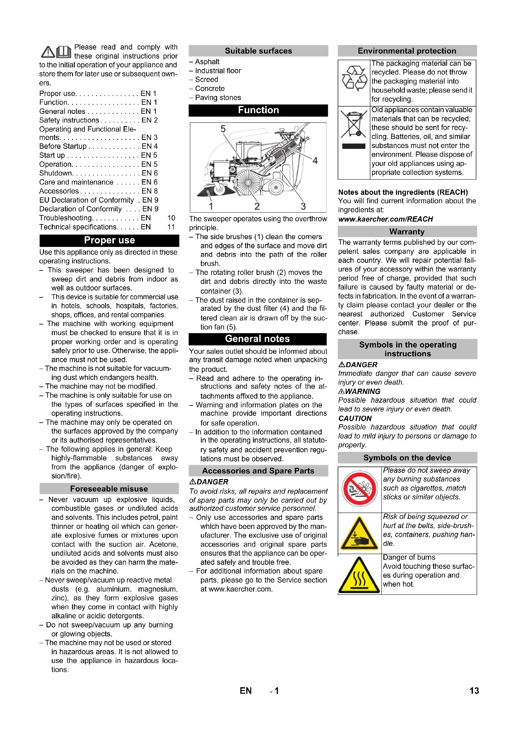
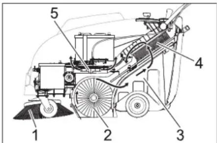
Technical diagram of a mechanical harvester with numbered parts labeled 1 to 5The sweeper operates using the overthrow principle.
- The side brushes (1) clean the corners and edges of the surface and move dirt and debris into the path of the roller brush.
- The rotating roller brush (2) moves the dirt and debris directly into the waste container (3).
- The dust raised in the container is separated by the dust filter (4) and the filtered clean air is drawn off by the suction fan (5).
General notes
Your sales outlet should be informed about any transit damage noted when unpacking the product.
- Read and adhere to the operating instructions and safety notes of the attachments affixed to the appliance.
- Warning and information plates on the machine provide important directions for safe operation.
– In addition to the information contained in the operating instructions, all statutory safety and accident prevention regulations must be observed.
Accessories and Spare Parts
△DANGER
To avoid risks, all repairs and replacement of spare parts may only be carried out by authorized customer service personnel.
- Only use accessories and spare parts which have been approved by the manufacturer. The exclusive use of original accessories and original spare parts ensures that the appliance can be operated safely and trouble free.
- For additional information about spare parts, please go to the Service section at www.kaercher.com.
Environmental protection

The packaging material can be recycled. Please do not throw the packaging material into household waste; please send it for recycling.
Old appliances contain valuable materials that can be recycled; these should be sent for recycling. Batteries, oil, and similar substances must not enter the environment. Please dispose of your old appliances using appropriate collection systems.
Notes about the ingredients (REACH)
You will find current information about the ingredients at:
www.kaercher.com/REACH
Warranty
The warranty terms published by our competent sales company are applicable in each country. We will repair potential failures of your accessory within the warranty period free of charge, provided that such failure is caused by faulty material or defects in fabrication. In the event of a warranty claim please contact your dealer or the nearest authorized Customer Service center. Please submit the proof of purchase.
Symbols in the operating instructions
△DANGER
Immediate danger that can cause severe injury or even death.
△WARNING
Possible hazardous situation that could lead to severe injury or even death.
CAUTION
Possible hazardous situation that could lead to mild injury to persons or damage to property.
Symbols on the device

Please do not sweep away any burning substances such as cigarettes, match sticks or similar objects.
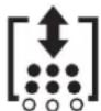
Risk of being squeezed or hurt at the belts, side-brushes, containers, pushing handle.
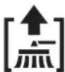
Danger of burns Avoid touching these surfaces during operation and when hot.
Safety instructions
Safety instructions concerning the operation
- The machine with working equipment must be checked to ensure that it is in proper working order and is operating safely prior to use. Otherwise, the appliance must not be used.
- If the appliance is used in hazardous areas (e.g. filling stations) the corresponding safety provisions must be observed. It is not allowed to use the appliance in hazardous locations.
- The operator must use the appliance properly. The person must consider the local conditions and must pay attention to third parties, in particular children, when working with the appliance.
- Prior to starting work, the operator must ensure that all protective devices are properly installed and function correctly.
- The operator of the appliance is liable for accidents with other individuals or their property.
- Ensure that the operator wears tight-fitting clothes. Wear sturdy shoes and avoid wearing loose-fitting clothes.
- Check the immediate vicinity prior to starting (e.g. children). Ensure sufficient visibility!
- Please remove the key, when not in use, to avoid unauthorised use of the appliance.
- When leaving, secure the device against unintentional movement.
- The appliance may only be used by persons who have been instructed in handling the appliance or have proven qualification and expertise in operating the appliance or have been explicitly assigned the task of handling the appliance.
- This device must not be used by any persons (including children) with restricted physical, sensory or mental abilities or those lacking in experience and knowledge.
- Children should be supervised to prevent them from playing with the appliance.
Safety information concerning the driving operation
⚠️Danger
Risk of injury!
Danger of tipping if gradient is too high.
- The falling and rising gradients in the direction of travel may not exceed 12% .
Danger of tipping on unstable ground. - Only use the machine on sound surfaces.
Danger of tipping with excessive sideways tilt.
– The gradient perpendicular to the direction of travel should not exceed 12%.
The travel speed must be adapted to the existing conditions.
Safety information concerning the transport of the appliance
- Mind the weight of the appliance during transport.
- Disconnect the battery and securely fasten the device for transport.
Safety instructions for battery-operated devices
Note: Warranty claims will be entertained only if you use batteries and chargers recommended by Kärcher.
- Always follow the instructions of the battery manufacturer and the charger manufacturer. Please follow the statutory requirements for handling and disposing batteries.
- Never leave the batteries in a discharged state; recharge them as soon as possible.
- Always keep the batteries clean and dry to avoid creep currents. Protect the batteries and avoid contact with impurities such as metal dust.
- Do not place tools or similar items on the battery. Risk of short-circuit and explosion.
- Always use 2 batteries of the same type!
- Do not work with open flames, generate sparks or smoke in the vicinity of a battery or a battery charging room. Danger of explosion.
- Only use batteries with terminal cover. Restore terminal cover in the event of loss.
- Do not touch hot parts of the machine such as the drive motor (risk of burns).
- Be careful while handling battery acid. Follow the respective safety instructions!
- Used batteries are to be disposed according to the EC guideline 91/157 EWG in an environment-friendly manner.
Safety information concerning maintenance and care
- Switch off the appliance and remove the ignition key prior to performing any cleaning or maintenance tasks on the appliance, replacing parts or switching over to another function.
- Always disconnect the battery when working on the electrics.
- Do not clean the appliance with a water hose or high-pressure water jet (danger of short circuits or other damage).
- Maintenance work may only be carried out by approved customer service outlets or experts in this field who are familiar with the respective safety regulations.
- Please observe the local safety regulations regarding portable commercially used appliances.
- Always use appropriate gloves while working on the device.
Safety devices
Cover
The device is equipped with a cover contact switch that switches off the motor as soon as the device cover is opened.
△DANGER
Risk of injury due to defective cover contact switch!
If the motor does not switch off when the device cover is opened, the cover contact switch is faulty. Do not operate or repair the device.
Main switch
→ In case of dangerous situations or in order to quickly switch off the device's main switch, turn the main switch to position "0/OFF".
To prevent unintentional start-up, turn the main switch to the "0/OFF" position and remove the key.
Operating and Functional Elements
text_image
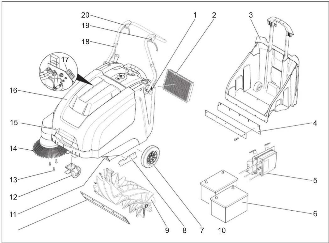
Exploded view diagram of a cleaning machine with numbered parts for identification1 Screw for fastening the push handle (2x)
2 Dust filter
3 Waste container
4 Rear sealing strip (at the waste container)
5 Charger
(KM 75/40 W Bp Pack only)
6 Batteries
(KM 75/40 W Bp Pack only)
7 Drive wheels
8 Side sealing strip
9 Roller brush
10 Front sealing strip
11 Bulk waste flap
12 Steering roller with fixed position brake
13 Fastener of the side brush
14 Side brushes
15 Cover lock
16 Cover
17 Battery charge plug (KM 75/40 W Bp only)
18 Push handle
19 Lever for forward drive
20 Lever to raise and lower the bulk waste flap
Operating field

text_image
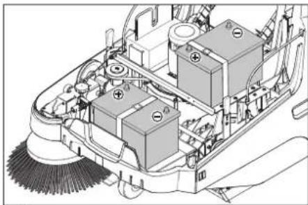
Labeled diagram of a vehicle interior with numbered components for identification1 Main switch
2 Lever for lowering and raising the side-brush
3 Locking screw of the dust filter cover
4 Locking bow of the waste container
5 Filter cleaning for dust filter
6 Wet/dry flap
Main switch

text_image
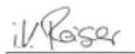
C B A 0 OFF 1| 0/OFF Motor off |
| 1 Motor on |
| A Remove the key |
| B Fault indication |
| C Battery display |
Remove the key
→ Turn the main switch using "0" position and pull it out.
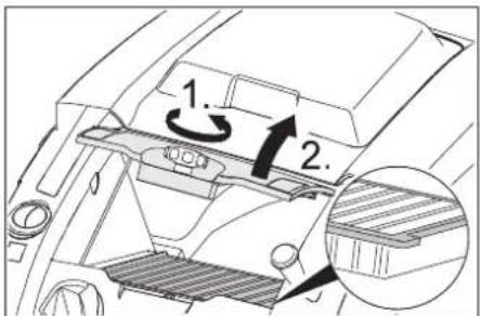
Open the device hood.
Note
The cover is unlocked with the key of the main switch.
text_image
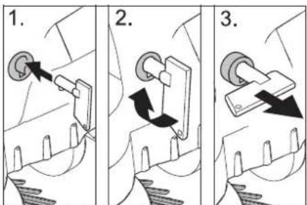
1. 2. 3.→ Insert the key for the main switch into the hood lock and rotate in a clockwise direction by 90°.
→ Pull the hood lock out by the key.
→ Open the device hood.
Close device hood
→ Close the appliance cover, the cover lock will lock automatically.
Before Startup
Unloading tips
△DANGER
Risk of injury, risk of damage! Observe the weight of the appliance when you load it!
| Net weight (transport weight) | |
| KM 75/40 W Bp 79 kg | |
| KM 75/40 W Bp Pack 125 kg | |
| Permissible overall weight | |
| KM 75/40 W Bp 205 kg | |
| KM 75/40 W Bp Pack 205 kg | |
Unloading
→ Remove the cardboard.
→ Remove the wooden blocks that secure the wheels and raise the device from the palette by hand.
→ Release parking brake.
Installing the pushing handle
→ Loosen the screws.
→ Align the pushing handle.
→ Tighten the screws.
Install side brush
Note: Remove the waste container and move the pushing handle to the front prior to tilting the appliance. Do not rest the appliance on the pushing handle.
→ Clip side brush on to driver and screw on.
Batteries
Safety notes regarding the batteries
Please observe the following warning notes when handling batteries:
 | Observe the directions on the battery, in the instructions for use and in the vehicle operating instructions! |
 | Wear an eye shield! |
 | Keep away children from acid and batteries! |
 | Risk of explosion! |
 | Fire, sparks, open light, and smoking not allowed! |
 | Danger of causticization! |
 | First aid! |
 | Warning note! |
 | Disposal! |
 | Do not throw the battery in the dustbin! |
Danger
Risk of explosion! Do not put tools or similar on the battery, i.e. on the terminal poles and cell connectors.
⚠Danger
Risk of injury! Ensure that wounds never come into contact with lead. Always clean your hands after having worked with batteries.
△DANGER
Risk of fire and explosion!
- Smoking and naked flames are strictly prohibited.
- Rooms where batteries are charged must have good ventilation because highly explosive gas is emitted during charging.
⚠Danger
Danger of causticization!
- Rinse thoroughly with lots of clear water if acid gets into the eye or comes in contact with the skin.
- Then consult a doctor immediately.
- Wash off the acid If it comes in contact with the clothes.
Recommended batteries
| Order No. | Volume Air | stream | |
| 60 Ah,Maintenance-free | 6.654-226.0* | 1,65** 0,6 | 6*** |
* Appliance requires 2 batteries
** in m³
*** in m³/h
Maximum battery dimensions
| Length Width | Height | |
| 267 mm | 177 mm | 190 mm |
Recommended chargers
| Order No. | |
| Charger | 6.654-225.0 |
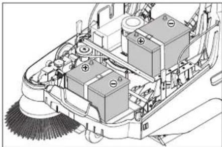
Installing and connecting the batteries
natural_image
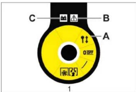
Technical diagram of a cleaning or cleaning machine with labeled components (no text or symbols present)Note
With the KM 75/40 W Bp Pack the battery and the charger are already built in.
→ Open the device hood.
→ Set the batteries on to the motor carrier.
→ Secure the batteries with the holding strap.
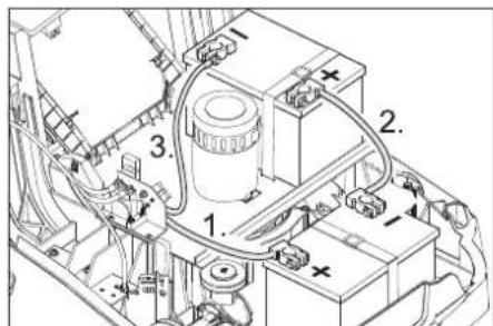
text_image
Technical diagram of an automotive battery pack with numbered components and wiring labels→ Connect pole terminal (red cable) to positive pole (+).
→ Fit the connection wires to the batteries.
→ Connect pole terminal to negative pole (-).
Note: Check that the battery pole and pole terminals are adequately protected with pole grease.
Only use batteries with terminal cover. Restore terminal cover in the event of loss.
CAUTION
Charge the batteries before commissioning the machine.
Charge the batteries
⚠ Danger
Risk of injury! The charger should be used only if the mains cable is in an undamaged state. Get the manufacturer, the customer service agent or a qualified person to immediately replace a damaged mains cable.
DANGER
Risk of electric shock. Observe supply network and fuse protection. Only use the charger in dry rooms with sufficient ventilation.
Note: The charging time for an empty battery is approx. 12 hours.
⚠Danger
Risk of injury! Comply with safety regulations on the handling of batteries. Observe the directions provided by the manufacturer of the charger.
Charging process - KM 75/40 W Bp Pack
Caution: Batteries may only be charged at room temperature!
Note: Normally, the device is equipped with maintenance-free batteries.
→ Open the cover.
→ Insert the mains plug of the charger into the socket.
Note: The charger is electronically controlled and ends the charging process automatically. All functions of the device are automatically interrupted during the charging process.
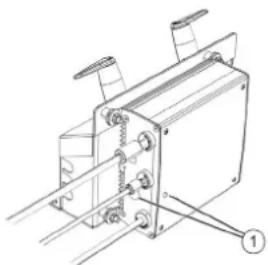
natural_image
Technical line drawing of a mechanical assembly with mounting brackets and a numbered component (no text or symbols)1 Battery status display
The battery status display shows the progress of the charging process when the mains plug is inserted:
| Batteries are being charged | flashes green |
| Batteries are charged lights | up green |
| Fault on the charger lights | up red |
| Error n from error table is present | flashes red n times with pause |
Error table:
| 1 Battery not connected |
| 2 Battery polarity reversed |
| 3 Battery deep discharged |
| 4 Problem with charging characteristic |
| 5 Power supply too hot |
| 6 Hardware fault |
| 7 Communication error (power supply mode) |
To ensure a long battery life, the battery should always be fully charged.
Charging process - KM 75/40 W Bp
→ Open the device hood.
→ Insert the charging cable of the charger in the charger box of the sweeper
→ Plug in mains connector and switch on charger.
After charging
■ KM 75/40 W Bp Pack
→ Disconnect the mains plug.
→ Wrap the mains cord around the cable holder of the charger.
→ Close cover.
■ KM 75/40 W Bp
→ Switch off the charger and remove the plug from the socket.
→ Hang out the charging cable out of the machine.
→ Close cover.
Remove the battery
→ Open the device hood.
→ Disconnect pole terminal to negative pole (-).
→ Unscrew the connection wires from the batteries.
→ Disconnect pole terminal to positive pole (+).
→ Losen the holding strap.
→ Remove the battery.
→ Dispose of the used battery according to the local provisions.
Start up
General notes
DANGER
Risk of injury! Switch off the appliance prior to removing the waste container.
Note: Start the appliance only when the hood is closed.
→ Park the sweeper on an even surface.
→ Switch off engine.
→ Lock parking brake.
Inspection and maintenance work
→ Check charging status of battery.
→ Check side brush.
→ Check roller brush.
→ Shake off dust filter.
→ Empty waste container.
Note: For description, see section on Care and maintenance.
Operation
⚠ Danger
Long hours of using the appliance can cause circulation problems in the hands on account of vibrations.
It is not possible to specify a generally valid operation time, since this depends on several factors:
– Proneness to blood circulation deficiencies (cold, numb fingers).
– Low ambient temperature. Wear warm gloves to protect hands.
– A firm grip impedes blood circulation.
- Continuous operation is worse than an operation interrupted by pauses.
In case of regular, long-term operation of the device and in case of repeated occurrence of the symptoms (e.g. cold, numb fingers) please consult a physician.
Starting the machine
→ Release parking brake.
Start the motor.
→ Turn the main switch to position "1".
Note: The roller brush and the side brush will rotate.
Drive the machine
Drive forward
→ Pull the lever for forward drive.
Note: The drive speed for forward drive can be adjusted steplessly depending on the position of the lever.
Dry run
→ Release the lever for forward drive. Device comes to a halt.
Driving over obstacles
Driving over fixed obstacles which are 30 mm high or less:
→ Raise bulk waste flap.
→ Drive forwards slowly and carefully.
Driving over fixed obstacles which are more than 30 mm high:
→ Only drive over these obstacles using a suitable ramp.
Sweeping mode
⚠Danger
Risk of injury! If the bulk waste flap is open, stones or gravel may be flung forwards by the roller brush. Make sure that this does not endanger persons, animals or objects.
CAUTION
Do not sweep up packing strips, wire or similar objects as this may damage the sweeping mechanism.
Note: To achieve an optimum cleaning result, the driving speed should be adjusted to take specific situations into account.
Sweeping with bulk waste flap raised
Note: To sweep up larger items up to a height of 50 mm, e.g. cigarette packs, the bulk waste flap must be raised briefly.
Raising bulk waste flap:
→ Pull the lever for raising the bulk waste flap.
Lowering the bulk waste flap:
→ Release the lever for raising the bull waste flap.
Note: An optimum cleaning result can only be achieved if the bulk waste flap has been lowered completely.
Sweeping with side brushes
→ Move the lever to lower the side brush to the front. The side brush will be lowered.
Sweeping dry floors
Note: During operation, the waste container should be emptied at regular intervals.
Note: During operation, the dust filter should be shaken off and cleaned at regular intervals.

→ Close wet/dry flap
Sweeping damp or wet floors
→ Open wet/dry flap.
Note: This protects the filter from moisture.
Battery display
The battery display shows the charging status of the batteries during operation:

| full glows green | |
| 30% capacity remaining | glows yellow |
| 10% capacity remaining | blinks red |
| Protection against total discharge; the appliance is switched off | glows red |
Fault display
The fault indicator shows whether there is a fault with the device:

Motor control fault flashes red
Cleaning the dust filter
→ Pull the handle of the filter clean-off out several times and reinsert it.
Emptying waste container
DANGER
Risk of injury! Switch off the appliance prior to removing the waste container.
Note: Make sure the seal strip is not damaged while emptying the waste container.
Note: The max. load of the waste container is 40 kg.
→ Shake off dust filter.
→ Pull lock bow of the waste container upward.
→ Pull out the waste container.
→ Empty waste container.
→ Push in the waste container.
→ Push lock bow of the waste container downward.
Turn off the appliance
Switch off engine.
→ Turn the main switch to position "0".
→ The side-brushes lift up.
→ Lock parking brake.
→ Turn the main switch using "0" position and pull it out.
Transport
△DANGER
Risk of injury and damage! Observe the weight of the appliance when you transport it.
→ Switch off engine.
→ Turn the main switch using "0" position and pull it out.
→ Lock parking brake.
→ Secure the wheels of the machine with wheel chocks.
→ Secure the machine with tensioning straps or cables.
→ When transporting in vehicles, secure the appliance according to the guidelines from slipping and tipping over.
natural_image
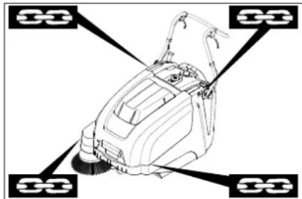
Line drawing of a cleaning or cleaning machine with four circular components (no text or symbols)1 Fastening area above the pushing handle
2 Fastening area under the device hood Note: Observe markings for fixing points on base frame (chain symbols).
Note: Do not kink the bowden or sheathed cables.
Storage
△DANGER
Risk of injury and damage! Note the weight of the appliance in case of storage.
Shutdown
If the sweeper is going to be out of service for a longer time period, observe the following points:
→ Park the sweeper on an even surface.
→ Switch off engine.
→ Turn the main switch using "0" position and pull it out.
→ Lock parking brake.
→ Lock the sweeper to ensure that it does not roll off.
→ Raise roller brush. Thus, engage both adjustment levers in the top boring.
→ The side-brushes lift up.
→ Clean the inside and outside of the sweeper.
→ Park the machine in a safe and dry place.
→ Disconnect batteries.
→ Charge batteries and recharge approx every 2 months.
Care and maintenance
General notes
– Maintenance work may only be carried out by approved customer service outlets or experts in this field who are familiar with the respective safety regulations.
– Mobile appliances used for commercial purposes are subject to safety inspections according to VDE 0701.
Cleaning
CAUTION
Risk of damage! Do not clean the appliance with a water hose or high-pressure water jet (danger of short circuits or other damage).
ATTENTION
Pull the mains plug out of the socket prior to cleaning.
Disconnect the plus terminal of the battery prior to cleaning.
Cleaning the inside of the machine
⚠Danger
Risk of injury! Wear dust mask and protective goggles.
→ Open the device hood.
→ Clean machine with a cloth.
→ Blow through machine with compressed air.
→ Close cover.
External cleaning of the appliance
→ Clean the machine with a damp cloth which has been soaked in mild detergent.
Note: Do not use aggressive cleaning agents.
Maintenance intervals
Maintenance by the customer
Daily maintenance:
→ Check the sweeping roller and the side brush for wear and wrapped belts.
→ Check function of all operator control elements.
→ Check functioning of all indicator lamps.
Weekly maintenance:
→ Check tension, wear and tear and functioning of the drive belts.
→ Check for smooth running of the Bowden cables and the moveable parts
→ Check the sealing strips in the sweeping area for position and wear.
→ Chek the sweeping track of the sweeping roller.
→ Clean the dust filter.
Note: For description, see section on Maintenance work.
Note: Where maintenance is carried out by the customer, all service and maintenance work must be undertaken by a qualified specialist. If required, a specialised Kärcher dealer may be contacted at any time.
Maintenance by Customer Service
Maintenance after the first month or 5 operating hours:
→ Carry out initial inspection.
Maintenance to be carried out every 50 operating hours
Maintenance to be carried out every 100 operating hours or every six months Maintenance to be carried out every 300 operating hours
Maintenance to be carried out every 500 operating hours or annually
Note: In order to safeguard warranty claims, all service and maintenance work during the warranty period must be carried out by the authorised Kärcher Customer Service in accordance with the maintenance booklet.
Maintenance Works
Preparation:
→ Park the sweeper on an even surface.
→ Turn the main switch using "0" position and pull it out.
→ Lock parking brake.
General notes on safety
△DANGER
Risk of injury!
The engine requires approx. 3-4 seconds to come to a standstill once it has been switched off. During this time, stay well clear of the working area.
⚠ WARNING
Allow the machine sufficient time to cool down before carrying out any maintenance and repair work.
Do not touch any hot parts, such as the drive motor.
ATTENTION
Pull the mains plug out of the socket prior to any maintenance work.
Disconnect the plus terminal of the battery prior to any maintenance work.
ATTENTION
Remove batteries and waste container, and swing the push handle forward prior to tilting the device. Do not park the device on the push handle.
Switch off the appliance prior to cleaning and performing any maintenance tasks or replacing parts.
Adjust the Bowden cable of the acceleration drive
This must be adjusted if the drive performance of the appliance becomes insufficient when driving uphill.
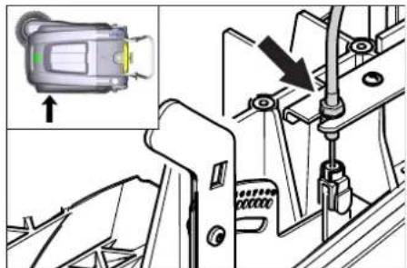
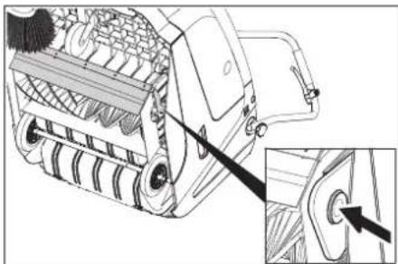
text_image
Technical diagram showing a device's internal components with an inset image of a device labeled 'Green' and directional arrow.→ Open the device hood.
→ Loosen counter-nut.
→ Adjust the adjustment screw.
→ Tighten the counter-nut.
Checking roller brush
→ Lock parking brake.
→ Remove the waste container.
→ Remove belts or cords from roller brush.
Replacing roller brush
Replacement is due if a visible deterioration in sweeping performance caused by bristle wear is evident.
ATTENTION
Remove the batteries prior to tilting the device.
Do not park the device on the push handle.
→ Lock parking brake.
→ Remove the waste container.
→ Remove the batteries.
→ Tilt the appliance rearward.
natural_image
Technical line drawing of a mechanical device with a magnified inset showing a detail (no text or symbols)→ Ift the waste flap, press in the bearing cap and swivel the roller brush toward the front.
→ Pull out roller brush.
→ Attach the new roller brush to the drive pin (left).
→ Engage the bearing cup into the boring of the roller brush swinging arm on the opposite side.
CAUTION
Risk of damage! Make sure that no bristles are jammed into the boring of the roller brush swinging arm.
Note: Once the new roller brush has been installed, the sweeping track must readjusted.
Check and adjust roller brush sweeping track
→ Raise the sweeper from the front and drive it on to a smooth, even surface covered with a visible layer of dust or chalk.
→ Lock parking brake.
→ Let the sweeping roller rotate for approx. 15-30 seconds.
→ Raise the sweeper at the front and drive it towards the side.
text_image
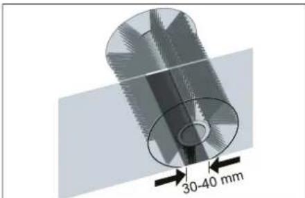
30-40 mmThe sweeping track should have an even rectangular shape which is between 30 and 40 mm wide.
| Setting range (-) 1...10 (+) | |
| Minimum sweeping track 1 | |
| Maximum sweeping track 10 | |
| New roller brush | 1...3 |
Adjust sweeping track:
→ Open the device hood.
→ Adjust the left and right adjustment le-vers and engage into the same boring.

text_image
R L L + - R +- Engage adjustment lever into the lower boring (+): Sweeping track becomes bigger
- Engage the adjustment lever into the upper boring (-): Sweeping track becomes smaller
→ Check sweeping mirror.
Replacing side brush
Replacement is due if a visible deterioration in sweeping performance caused by bristle wear is evident.
Note: Remove the waste container and move the pushing handle to the front prior to tilting the appliance. Do not rest the appliance on the pushing handle.
→ Unscrew 3 screws from the underside of the side brush.
→ Remove the wiper blade.
→ Clip new side brushes on to driver and screw on.
Adjust side-brush lowering
Adjustment is necessary if a visible deterioration in sweeping performance caused by side-brush is evident.
→ Open the device hood.
→ Release the wing nut.
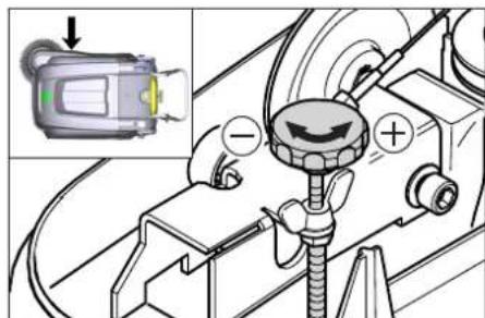
text_image
Technical diagram showing mechanical assembly with labeled components and a magnified inset of a device component.→ Adjust the adjustment screw.
→ Tighten the wing nut.
Adjust the raising of the bulk waste flap
- Adjustment is necessary if the bulk waste flap cannot be raised wide enough.
- The Bowden cable needs to be released a little if the sweeper results become poorer, for e.g. due to the wearing of the front lip.
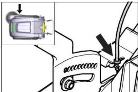
text_image
Diagram showing a device with an inset highlighting a component, likely illustrating a mechanical or electrical assembly.→ Open the device hood.
→ Loosen counter-nut.
→ Adjust the adjustment screw.
→ Tighten the counter-nut.
Adjusting and replacing sealing strips
Note: Remove the waste container and move the pushing handle to the front prior to tilting the appliance. Do not rest the appliance on the pushing handle.
■ Front sealing strip
→ Loosen the fastening screws of the sealing strip.
→ Adjust or replace sealing strip.
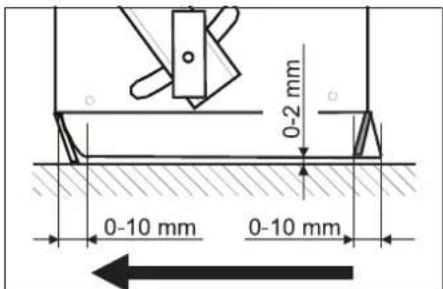
text_image
0-2 mm 0-10 mm 0-10 mm→ Set the distance between the sealing strip and the floor so that the bottom edge trails behind at a distance of between 0-10 mm.
→ Adjust sealing strip.
→ Tighten the fastening of the sealing strip.
■ Rear sealing strip
→ Remove the waste container.
→ Loosen the fastening screws of the sealing strip.
→ Adjust or replace sealing strip.
Set the distance between the sealing strip and the floor so that the bottom edge trails behind at a distance of between 0-10 mm.
→ Tighten the fastening of the sealing strip.
■ Side sealing strips
→ Loosen the fastening screws of the sealing strip.
→ Adjust or replace sealing strip.
→ To set the floor clearance, insert a sheet with a thickness of max. 2 mm under the sealing strip.
→ Adjust sealing strip.
→ Tighten the fastening of the sealing strip.
Replacing dust filter
⚠ WARNING
Empty waste container before replacing dust filter. Wear a dust mask when working around the dust filter. Observe safety regulations on the handling of fine particulate material.
CAUTION
Risk of damage!
→ Do not rinse out the dust filter.
→ Lok parking brake.
→ Shake off dust filter.
text_image
1. 2.→ Open the locking screw of the dust filter cover in an anticlockwise direction.
→ Lift the dust filter cover.
→ Replace dust filter Make sure the dust filter is inserted correctly (see figure).
→ Screw in the locking screw all the way.
CAUTION
If the locking screw is not tightened all the way, there may be damages.
Note: Make sure when installing the new filter that the fins are not damaged.
Replace fuse/relay
■ KM 75/40 W Bp
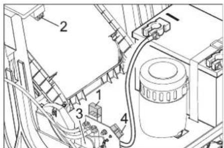
text_image
Technical diagram of a mechanical assembly with numbered components, likely a valve or pump unit.1 Fuse F1 (50 A)
2 Fuse F2 (2 A)
3 Relay
4 Battery charge plug
→ Open the cover.
→ Replace defective fuse or relay.
■ KM 75/40 W Bp Pack
The fuse is located on the battery terminal.
Accessories
| Side-brushes, soft 6.905-626.0 | |
| For fine dust on inside surfaces; wetness resistant. | |
| Roller-brush, soft 6.906-886.0 | |
| With natural bristles: especially for sweeping fine dust on smooth floors indoors.Not resistant to wetness; do not use on abrasive surfaces! | |
| Roller-brush, hard 6.906-885.0 | |
| For removing stubborn dirt in the external area; resistant to moisture. | |
| Roller brush, antistatic | 6.906-950.0 |
| For statically chargeable surfaces such as carpet or artificial turf | |
| Carpet sweeping unit | 2.641-571.0 |
| Includes: Lint trap, antistatic roller brush, triple steering roller | |
EU Declaration of Conformity
We hereby declare that the machine described below complies with the relevant basic safety and health requirements of the EU Directives, both in its basic design and construction as well as in the version put into circulation by us. This declaration shall cease to be valid if the machine is modified without our prior approval.
Product: Vacuum sweeper
Type: 1.049-xxx
Relevant EU Directives
2006/42/EC (+2009/127/EC)
2014/30/EU
2000/14/EC
Applied harmonized standards
EN 55012: 2007 + A1: 2009
EN 60335-1
EN 60335-2-72
EN 61000-6-2: 2005
EN 62233: 2008
EN IEC 63000: 2018
Applied national standards
Applied conformity evaluation method
2000/14/EC: Appendix V
Sound power level dB(A)
Measured: 86
Guaranteed: 88
The signatories act on behalf of and with of the authority of the company management.

H. Jenner
Chairman of the Board of Management

S. Reiser
Director Regulatory Affairs & Certification
Documentation supervisor:
S. Reiser
Alfred Kärcher SE & Co. KG
71364 Winnenden (Germany)
Tel.: +49 7195 14-0
Fax: +49 7195 14-2212
Winnenden, 2021/02/01
Declaration of Conformity
We hereby declare that the product described below complies with the relevant provisions of the following UK Regulations, both in its basic design and construction as well as in the version put into circulation by us. This declaration shall cease to be valid if the product is modified without our prior approval.
Product: Vacuum sweeper
Type: 1.049-xxx
Currently applicable UK Regulations
S.I. 2008/1597 (as amended)
2004/108/EC
S.I. 2001/1701 (as amended)
S.I. 2012/3032 (as amended)
Designated standards used
EN 55012: 2007 + A1: 2009
EN 60335-1
EN 60335-2-72
EN 61000-6-2: 2005
EN 62233: 2008
EN IEC 63000: 2018
National standards used
Applied conformity assessment procedure
S.I. 2001/1701 (as amended): Schedule 8
Sound power level dB(A)
Measured: 86
Guaranteed: 88
The signatories act on behalf of and with of the authority of the company management.

Chairman of the Board of Management

S. Reiser
Director Regulatory Affairs & Certification
Documentation supervisor:
S. Reiser
Alfred Kärcher SE & Co. KG
71364 Winnenden (Germany)
Tel.: +49 7195 14-0
Fax: +49 7195 14-2212
Winnenden, 2021/02/01
Troubleshooting
| Fault Remedy | |
| Appliance cannot be started | The cover contact switch has switched off the device. Closing the cover |
| Charge the batteries | |
| Check overload fuse | |
| Inform Kärcher Customer Service. | |
| Engine is running but machine is not moving | Adjust the Bowden cable of the acceleration drive |
| Checking the V-Belt | |
| Inform Kärcher Customer Service. | |
| Device comes to halt while climbing a slope | Drive over a path with lesser slope |
| Check overload fuse | |
| Adjust the Bowden cable of the acceleration drive | |
| Checking the V-Belt | |
| Inform Kärcher Customer Service. | |
| The brush roller stops, fault display illuminates red | Turn the main switch to "OFF", check brush for obstructing objects. If applicable, use on a less inclined surface. Turn on the main switch. After repeating this process four times, the control will initiate a forced break of 2 minutes to cool off. During this period the appliance cannot be started. |
| Machine is not sweeping properly | Check roller brush and side brushes for wear, replace if necessary. |
| Check function of bulk waste flap | |
| Release the Bowden cable of the bulk waste flap (adjustment screw) | |
| Check belts for tension and functioning; replace, if required | |
| Adjust roller mirror | |
| Replacing roller brush | |
| Inform Kärcher Customer Service. | |
| Dust gathers in the machine Check | function of bulk waste flap |
| Release the Bowden cable of the bulk waste flap (adjustment screw) | |
| Check dust filter, clean or replaceDo not rinse out the dust filter. | |
| Empty waste container | |
| Replace sealing profile at the waste container | |
| Check the seal on the dust filter | |
| Check sealing strips for wear, adjust or replace as required | |
| Poor cleaning performance at edges | Adjust side-brush lowering |
| Replace side brush | |
| Lower the side brushes | |
| Check the drive belt of the side brush | |
| Inform Kärcher Customer Service. | |
| Side-brush raising does not function | Check Bowden cable of the side-brush raising |
| Inform Kärcher Customer Service. | |
| The new roller brush brushes against the waste container | Correct the setting of the sweep track; for this, engage both adjustment levers into the upper boring (1...3) |
Technical specifications
| KM 75/40 W Bp KM 75/40 W Bp Pack | |||
| Machine data | |||
| Length x width x height (pushing handle unfolded) mm 1430 x 750 x 1190 | 1430 x 750 x | 1190 | |
| Length x width x height (pushing handle folded in) mm 1160 x 750 x 930 | 1160 x 750 x | 930 | |
| Weight (without batteries) kg 79 79 | |||
| Weight (with batteries) kg 125 125 | |||
| Permissible overall weight kg 205 205 | |||
| Driving and sweeping speed km/h 4,5 4,5 | |||
| Climbing capability (max.) % 12 12 | |||
| Roller brush diameter | mm 265 265 | ||
| Side brush diameter | mm 410 410 | ||
| Surface area, max. | m3/h | 3400 | 3400 |
| Working width without side brushes | mm 550 550 | ||
| Working width with side-brush | mm 750 750 | ||
| Volume of waste container | I | 40 40 | |
| Protection type, drip-proof | -- | IPX 3 | IPX 3 |
| Engine | |||
| Type | -- | DC permanent solenoid motorDirection of rotation, right | |
| Voltage | V | 24 24 | |
| Rated current | A | 22 22 | |
| Rated power | W | 400 400 | |
| Speed | 1/min | 2750 | 2750 |
| Type of protection | -- | IP 20 | IP 20 |
| Battery | |||
| Type | -- | -- | 2x 12 V GiV |
| Capacity | Ah | -- | 60 (5h) |
| Weight | kg | ||
| Charging time for fully discharged battery | h | -- | 12 |
| Operating time after frequent charging | h | -- | ca. 1,5-2 |
| Charger | |||
| Mains voltage | V~ | -- | 230 |
| Output voltage | V | -- | 24 |
| Charging current | A | -- | 10 |
| Mains frequency | Hz | -- | 50/60 |
| Electrical fuses | |||
| Central | A | 50 50 | |
| Fuse for controls | A | 2 | -- |
| Protection against total discharge | -- | via relay | via relay |
| Charger | --- | T4A / 250 V AC | |
| Filter and vacuum system | |||
| Filter surface area, fine dust filter | m2 | 1,8 1,8 | |
| Category of use - filter for non-hazardous dust | -- | L | L |
| Nominal vacuum, suction system | mbar | 5 | 5 |
| Nominal volume flow, suction system | l/s | 45 | 45 |
| Working conditions | |||
| Operating temperature | °C | -5 and +40 | -5 and +40 |
| Charging temperature | --- | Room temperature | |
| Air humidity, non-condensing | % | 0 - 90 | 0 - 90 |
| Values determined as per EN 60335-2-72 | |||
| Sound pressure level LpA | dB(A) | 71 71 | |
| Uncertainty KpA | dB(A) | 3 | 3 |
| Sound power level LwA + Uncertainty KwA | dB(A) | 88 88 | |
| Uncertainty KwA | 2 | 2 | |
| Hand-arm vibration value | m/s2 | 3,7 3,7 | |
| Uncertainty K | m/s2 | 0,2 0,2 | |
Subject to technical changes.
text_image
Technical diagram of a mechanical device with numbered parts labeled 1 to 5www.kaercher.com/REACH
Garantie
text_image
Exploded view diagram of a cleaning machine with numbered parts for identificationtext_image
Labeled diagram of a vehicle interior with numbered components for identificationnatural_image
Technical line drawing of a cleaning or cleaning machine with labeled components (no text or symbols present)Remarque
text_image
Technical diagram of a battery system with labeled components and wiring connectionsnatural_image
Technical line drawing of a mechanical assembly with mounting brackets and a numbered component (no text or symbols)natural_image
Line drawing of a cleaning or cleaning device with four circular components (no text or symbols)text_image
Technical diagram showing a device with an inset image of a sensor or connector, highlighting a component with an arrow.natural_image
Technical illustration of a mechanical device with a magnified inset showing a close-up detail (no text or symbols present)text_image
R L L + - R +text_image
Technical diagram showing a mechanical assembly with labeled components and an inset image of a device with a green indicator light.text_image
Diagram showing a car interior with a device lock and a warning symbol indicating mechanical adjustment.text_image
Technical diagram of a mechanical or electrical component with numbered parts labeled 1 to 4Brosse rotative, souple 6.906-886.0
2006/42/CE (+2009/127/CE)
2014/30/UE
2000/14/CE
Chairman of the Board of Management
S. Reiser
Director Regulatory Affairs & Certification
71364 Winnenden (Germany)
Tel.: +49 7195 14-0
Fax: +49 7195 14-2212
Winnenden, 2021/02/01
text_image
Technical diagram of a mechanical harvester with numbered parts labeled 1 through 5www.kaercher.com/REACH
Garanzia
text_image
Exploded view diagram of a cleaning machine with numbered parts for identificationtext_image
Labeled diagram of a vehicle interior with numbered components for identificationnatural_image
Technical diagram of an electric cleaning or cleaning device with labeled components (no text or symbols present)Indicazione
text_image
Technical diagram of an electrical or mechanical device with numbered components and labeled partsnatural_image
Technical line drawing of a mechanical assembly with no visible text or symbolsnatural_image
Line drawing of a cleaning or cleaning machine with four circular components (no text or symbols)text_image
Technical diagram showing a mechanical assembly with an inset image of a device and directional arrows indicating movement or force.natural_image
Technical illustration of a mechanical device with a close-up inset showing a component detail (no text or symbols present)text_image
R L L + - R + -text_image
Technical diagram showing a mechanical assembly with labeled components and an inset image of a device with a warning symbol.text_image
Diagram showing a device's internal connection with an inset highlighting the component and directional arrowtext_image
Technical diagram of a mechanical assembly with numbered components, likely a valve or pump assembly.2006/42/CE (+2009/127/CE)
2014/30/UE
2000/14/CE

Chairman of the Board of Management
S. Reiser
Director Regulatory Affairs & Certification
71364 Winnenden (Germany)
Tel.: +49 7195 14-0
Fax: +49 7195 14-2212
Winnenden, 2021/02/01
text_image
Technical diagram of a mechanical harvester with numbered parts labeled 1 through 5www.kaercher.com/REACH
Garantie
text_image
Exploded view diagram of a cleaning machine with numbered parts for identificationtext_image
Labeled diagram of a vehicle interior with numbered components for identificationnatural_image
Technical line drawing of a cleaning or cleaning machine with labeled components (no text or symbols present)Tip
text_image
Technical diagram of a battery pack with labeled components and wiring connectionsnatural_image
Technical line drawing of a mechanical assembly with no visible text or symbols1 Weergave batterijstatus
natural_image
Line drawing of a cleaning or cleaning machine with four circular components, no text or symbols present.text_image
Technical diagram showing a mechanical assembly with an inset image of a device component and directional arrows indicating movement or force.→ Apparaatkap openen.
→ Contramoer lossen.
→ Instelschroef verstellen.
→ Contramoer vastschroeven.
Veegrol controleren
natural_image
Technical illustration of a mechanical device with internal components and a close-up inset showing a pin (no text or symbols present)text_image
R L L + - R +text_image
Technical diagram showing mechanical assembly with labeled components and a magnified inset of a device component.text_image
Diagram showing a device with an inset close-up highlighting a component, likely illustrating a mechanical or electrical assembly.→ Apparaatkap openen.
→ Contramoer lossen.
→ Instelschroef verstellen.
→ Contramoer vastschroeven.
text_image
Technical diagram of a mechanical assembly with numbered components for identification1 Zekering F1 (50 A)
2 Zekering F2 (2 A)
3 Relais
4 Contactstekker opladen accu
→ Open de apparaatkap.
→ Defecte zekering of relais vervangen.
■ KM 75/40 W Bp Pack
Chairman of the Board of Management

S. Reiser
Director Regulatory Affairs & Certification
71364 Winnenden (Germany)
Tel.: +49 7195 14-0
Fax: +49 7195 14-2212
Winnenden, 2021/02/01
Hulp bij storingen
text_image
Technical diagram of a mechanical harvester with numbered parts labeled 1 to 5www.kaercher.com/REACH
Garantía
Interruptor principal
text_image
Exploded view diagram of a cleaning machine with numbered parts for identification and assembly reference.text_image
Labeled diagram of a vehicle interior with numbered components for identificationInterruptor principal
text_image
C B A 0 OFF 1natural_image
Technical diagram of a cleaning or cleaning device with labeled components (no text or symbols present)Nota
text_image
Technical diagram of a battery pack with labeled components and wiring connectionsnatural_image
Technical line drawing of a mechanical assembly with mounting brackets and a numbered component (no text or symbols)natural_image
Line drawing of a cleaning or cleaning machine with four circular components, no text or symbols present.text_image
Technical diagram showing a device's internal components with an inset image of a sensor or sensor device and directional arrows indicating assembly or inspection.natural_image
Technical line drawing of a mechanical device with a magnified inset showing a detail (no text or symbols)text_image
R L L + - R +text_image
Technical diagram showing mechanical assembly with labeled components and a magnified inset of a device component.text_image
Diagram showing a car seatbelt switch with an inset image of the device's lock mechanism.text_image
Technical diagram of a mechanical assembly with numbered components for identification1 Fusible F1 (50 A)
2 Fusible F2 (2 A)
3 R e l é
2006/42/CE (+2009/127/CE)
2014/30/UE
2000/14/CE
Chairman of the Board of Management

S. Reiser
Director Regulatory Affairs & Certification
71364 Winnenden (Germany)
Tel.: +49 7195 14-0
Fax: +49 7195 14-2212
Winnenden, 2021/02/01
text_image
Technical diagram of a mechanical device with numbered parts labeled 1 to 5www.kaercher.com/REACH
Garantia
Interruptor principal
text_image
Exploded view diagram of a cleaning machine with numbered parts for identificationtext_image
Labeled diagram of a vehicle interior with numbered components for identificationInterruptor principal

text_image
C B A 0 OFF 1Montar e conectar as baterias
natural_image
Technical illustration of a cleaning or cleaning machine with labeled components (no text or symbols present)Aviso
text_image
Technical diagram of a mechanical or electrical component with numbered parts and labeled connectorsCarregar as baterias
⚠ Perigo
natural_image
Technical line drawing of a mechanical assembly with mounting brackets and a numbered component (no text or symbols)natural_image
Line drawing of a cleaning or cleaning device with four circular components (no text or symbols)text_image
Technical diagram showing a device with an inset image of a sensor or sensor device and directional arrows indicating assembly or operation.natural_image
Technical line drawing of a mechanical device with a close-up inset showing a component detail (no text or symbols)text_image
R L L + - R +text_image
Technical diagram showing a mechanical assembly with labeled components and an inset image of a device with a green indicator light.→ Ajustar o parafuso de ajuste.
text_image
Diagram showing a device with an orange sensor and a magnified inset highlighting the component's internal structure.text_image
Technical diagram of an industrial machine with numbered components and wiring labels1 Fusível F1 (50 A)
2 Fusível F2 (2 A)
3 R e l é
2006/42/CE (+2009/127/CE)
2014/30/UE
2000/14/CE
71364 Winnenden (Germany)
Tel.: +49 7195 14-0
Fax: +49 7195 14-2212
Winnenden, 2021/02/01
text_image
Technical diagram of a mechanical device with numbered parts labeled 1 to 5www.kaercher.com/REACH
Garanti
text_image
Exploded view diagram of a cleaning machine with numbered parts for identificationtext_image
Labeled diagram of a vehicle interior with numbered components for identificationnatural_image
Technical diagram of a cleaning or cleaning machine with labeled components (no text or symbols present)OBS
text_image
Technical diagram of an automotive battery pack with labeled components and wiring connectionsnatural_image
Technical line drawing of a mechanical assembly with no visible text or symbols1 Batteristatusvisning
natural_image
Line drawing of a cleaning or cleaning machine with four circular components, no text or symbols presenttext_image
Technical diagram showing a device with an inset image of a sensor or connector, highlighting a component with an arrow.→ Åbn apparatets hætte.
→ Løsne kontramøtrikken.
→ Juster stilleskruen.
→ Stram kontramøtrikken.
Kontrol af fejevalsen
natural_image
Technical illustration of a mechanical device with a close-up inset showing a pin inserted into a corner (no text or symbols present)text_image
R L L + - R +text_image
Technical diagram showing a mechanical assembly with labeled components and an inset image of a device with a green indicator light.text_image
Diagram showing a car interior with a highlighted sensor device and directional arrow, likely illustrating a diagnostic or safety concept.→ Åbn apparatets hætte.
→ Løsne kontramøtrikken.
→ Juster stilleskruen.
→ Stram kontramøtrikken.
text_image
Technical diagram of a mechanical assembly with numbered components for identification1 Sikring F1 (50 A)
2 Sikring F2 (2 A)
3 R e l æ
4 Batteriopladningsstik
→ Åbn maskinhjelm.
→ Udskift defekt sikring eller relæ.
■ KM 75/40 W Bp Pack
2006/42/EF (+2009/127/EF)
2014/30/EU
2000/14/EF

Chairman of the Board of Management

S. Reiser
Director Regulatory Affairs & Certification
71364 Winnenden (Germany)
Tel.: +49 7195 14-0
Fax: +49 7195 14-2212
Winnenden, 2021/02/01
Hjælp ved fejl
text_image
Technical diagram of a mechanical harvester with numbered parts labeled 1 to 5www.kaercher.com/REACH
Garanti
text_image
Exploded view diagram of a cleaning machine with numbered parts for identificationtext_image
Labeled diagram of a vehicle interior with numbered components for identificationnatural_image
Technical line drawing of a cleaning or cleaning machine with labeled components (no text or symbols)Merknad
text_image
Technical diagram of an automotive battery system with labeled components and wiring connectionsnatural_image
Technical line drawing of a mechanical assembly with gears and linkages (no text or symbols)1 Batteristatusindikator
Batteristatusindikatoren viser fremdriften for ladingen när nettpluggen er satt inn:
natural_image
Line drawing of a cleaning or cleaning machine with four circular components, no text or symbols present.text_image
Technical diagram showing a mechanical assembly with an inset image of a device labeled 'LED' and directional arrow indicating motion.→ Åpne dekselet på maskinen.
→ Løsne kontramutter.
→ Reguler stillskruen.
→ Skru fast kontramutter.
Kontrollere feievalsen
natural_image
Technical illustration of a mechanical device with a close-up inset showing a pin inserted into a component (no text or symbols present)→ Løft grovsmussklaffen, skyv inn lager-skål og sving feievalsen forover.
→ Ta av feievalsen.
→ Sett inn ny feievalse på drivtappen (venstre).
→ På motsatt side, la lagerskålen gå i lås i hullet på feievalsesvingarmen.
FORSIKTIG
text_image
R L L + - R +text_image
Technical diagram showing a mechanical assembly with labeled components and an inset image of a device with a green indicator light.→ Reguler stillskruen.
→ Stram vingemutter.
text_image
Diagram showing a car seatbelt switch with an inset image of the device's cable and adjustment mechanism.→ Åpne dekselet på maskinen.
→ Løsne kontramutter.
→ Reguler stillskruen.
→ Skru fast kontramutter.
→ Åpne dekselet på maskinen.
→ Løsne kontramutter.
→ Reguler stillskruen.
→ Skru fast kontramutter.
text_image
Technical diagram of a mechanical assembly with numbered components for identification1 Sikring F1 (50 A)
2 Sikring F2 (2 A)
3 R e l é
4 Batteriladekontakt
→ Åpne apparathetten.
→ Skift defekt sikring eller relé.
■ KM 75/40 W Bp Pack
2006/42/EF (+2009/127/EF)
2014/30/EU
2000/14/EF
2000/14/EF: Vedlegg V
Lydeffektnivå dB(A)
Målt: 86
Garantert: 88
71364 Winnenden (Germany)
Tel.: +49 7195 14-0
Fax: +49 7195 14-2212
Winnenden, 2021/02/01
Feilretting
text_image
Technical diagram of a mechanical harvester with numbered parts labeled 1 to 5www.kaercher.com/REACH
Garanti
text_image
Exploded view diagram of a cleaning machine with numbered parts for identificationtext_image
Labeled diagram of a vehicle interior with numbered components for identificationnatural_image
Technical line drawing of a cleaning or cleaning machine with labeled components (no text or symbols present)Hänvisning
text_image
Technical diagram of a vehicle battery pack with numbered components and wiring labelsnatural_image
Technical line drawing of a mechanical assembly with no visible text or symbols1 Batteristatusindikator
natural_image
Line drawing of a cleaning or cleaning machine with four circular control symbols around it (no text or labels)text_image
Technical diagram showing a mechanical assembly with an inset image of a device component and directional arrow indicating motion or force.→ Öppna aggregatkåpa.
→ Lossa kontramutter.
→ Justera ställskruv.
→ Skruva fast kontramutter.
Inspektera sopvalsen
natural_image
Technical line drawing of a mechanical device with a close-up inset showing a detail (no text or symbols)→ Lyft upp grovsmutsluckan, tryck in la-
text_image
R L L + - R + -text_image
Technical diagram showing a device with labeled components and an inset image of a device with a green indicator light.text_image
Diagram showing a car's door panel with an inset image of a device labeled 'U' and a warning symbol.→ Öppna aggregatkåpa.
→ Lossa kontramutter.
→ Justera ställskruv.
→ Skruva fast kontramutter.
text_image
Technical diagram of a mechanical assembly with numbered components, likely an engine or pump unit.1 Säkring F1 (50 A)
2 Säkring F2 (2 A)
3 R e l ä
4 Kontakt till batteriladdare

Chairman of the Board of Management

S. Reiser
Director Regulatory Affairs & Certification
71364 Winnenden (Germany)
Tel.: +49 7195 14-0
Fax: +49 7195 14-2212
Winnenden, 2021/02/01
text_image
Technical diagram of a mechanical harvester with numbered parts labeled 1 to 5www.kaercher.com/REACH
Takuu
text_image
Exploded view diagram of a cleaning machine with numbered parts for identificationtext_image
Labeled diagram of a vehicle interior with numbered components for identificationnatural_image
Technical line drawing of a cleaning or cleaning machine with labeled components (no text or symbols present)Huomautus
text_image
Technical diagram of an automotive battery pack with labeled components and wiring connectionsnatural_image
Technical line drawing of a mechanical assembly with no visible text or symbols1 Akkutilan näyttö
natural_image
Line drawing of a cleaning or cleaning machine with four circular components, no text or symbols presenttext_image
Technical diagram showing a device with an inset image of a sensor or connector, highlighting a component with an arrow.natural_image
Technical illustration of a mechanical device with a close-up inset showing a component detail (no text or symbols)text_image
R L L + - R +text_image
Technical diagram showing mechanical assembly with labeled components and a magnified inset of a device component.text_image
Diagram showing a car's seatbelt switch mechanism with an inset image of the device's cable and adjustment arrow.text_image
Technical diagram of a mechanical assembly with numbered components for identification1 Sulake F1 (50 A)
2 Sulake F2 (2 A)
3 R e l e
4 Akun latauspistoke
→ Avaa laitesuoja.
→ Vaihda viallinen sulake tai rele.
■ KM 75/40 W Bp Pack
Chairman of the Board of Management

S. Reiser
Director Regulatory Affairs & Certification
71364 Winnenden (Germany)
Tel.: +49 7195 14-0
Fax: +49 7195 14-2212
Winnenden, 2021/02/01
Häiriöapu
text_image
Technical diagram of a mechanical device with numbered parts labeled 1 to 5www.kaercher.com/REACH
Εγγύηση
text_image
Exploded view diagram of a cleaning machine with numbered parts for identificationtext_image
Labeled diagram of a vehicle interior with numbered components for identificationnatural_image
Technical diagram of a cleaning or cleaning machine with labeled components (no text or symbols present)Υπόδειξη
text_image
Technical diagram of an automotive battery pack with numbered components and wiring annotationsnatural_image
Technical line drawing of a mechanical device with mounting brackets and wiring (no text or symbols)natural_image
Line drawing of a cleaning or cleaning machine with four circular components, no text or symbols present.text_image
Technical diagram showing a device connection with an inset image of a sensor device and directional arrows indicating assembly or inspection.natural_image
Technical illustration of a mechanical device with a close-up inset showing a pin or knob (no text or symbols present)text_image
R L L + - R + -text_image
Technical diagram showing mechanical assembly with labeled components and a magnified inset of a device component.text_image
Diagram showing a device with a lock and cable connector, labeled with an inset image of the device's internal structure.text_image
Technical diagram of a mechanical assembly with numbered components, likely a valve or pump unit.Chairman of the Board of Management

S. Reiser
Director Regulatory Affairs & Certification
71364 Winnenden (Germany)
Tel.: +49 7195 14-0
Fax: +49 7195 14-2212
Winnenden, 2021/02/01
Βλάβη Αντιμετώπιση
www.kaercher.com/REACH
Garanti
text_image
Exploded view diagram of a cleaning machine with numbered parts for identificationtext_image
Labeled diagram of a vehicle interior with numbered components for identificationnatural_image
Technical line drawing of a mechanical assembly with mounting brackets and a numbered component (no text or symbols)natural_image
Line drawing of a cleaning or cleaning machine with four circular components, no text or symbols presenttext_image
Technical diagram showing a mechanical assembly with an inset image of a device labeled 'LED' and directional arrow indicating motion.natural_image
Technical illustration of a mechanical device with a close-up inset showing a pin inserted into a corner (no text or symbols present)text_image
R L L + - R +text_image
Technical diagram showing mechanical assembly with labeled components and a magnified inset of a device component.text_image
Diagram showing a device with a lock and plug, labeled with an inset image of the device's internal structure.text_image
Technical diagram of an industrial machine with numbered components for identification1 Sigorta F1 (50 A)
2 Sigorta F2 (2 A)
3 R ö l e
4 Akü şarj soketi

Chairman of the Board of Management

S. Reiser
Director Regulatory Affairs & Certification
71364 Winnenden (Germany)
Tel.: +49 7195 14-0
Fax: +49 7195 14-2212
Winnenden, 2021/02/01
Arizalarda yardım
text_image
Technical diagram of a mechanical device with numbered parts labeled 1 to 5www.kaercher.com/REACH
Гарантия
text_image
Exploded view diagram of a cleaning machine with numbered parts for identificationtext_image
Labeled diagram of a vehicle interior with numbered components for identificationnatural_image
Technical diagram of a cleaning or cleaning machine with labeled components (no text or symbols present)Указание
text_image
Technical diagram of an automotive battery pack with numbered components and wiring labelsnatural_image
Technical line drawing of a mechanical assembly with mounting brackets and a numbered component (no text or symbols)natural_image
Line drawing of a cleaning or cleaning machine with four circular components (no text or symbols)text_image
Technical diagram showing a device with an inset image of a sensor or camera component and directional arrows indicating assembly or operation.natural_image
Technical line drawing of a mechanical device with internal components and an inset showing a close-up detail (no text or symbols)text_image
R L L + - R +text_image
Technical diagram showing mechanical assembly with labeled components and a magnified inset of a device component.text_image
Diagram showing a device's cable or connector adjustment with an inset image highlighting the component.text_image
Technical diagram of a mechanical assembly with numbered components for identificationDirector Regulatory Affairs & Certification
71364 Winnenden (Germany)
Tel.: +49 7195 14-0
Fax: +49 7195 14-2212
Winnenden, 2021/02/01
text_image
Technical diagram of a mechanical harvester with numbered parts labeled 1 to 5www.kaercher.com/REACH
Garancia
text_image
Exploded view diagram of a cleaning machine with numbered parts for identificationtext_image
Labeled diagram of a vehicle interior with numbered components for identificationnatural_image
Technical line drawing of a cleaning or cleaning machine with labeled components (no text or symbols)Megjegyzés
text_image
Technical diagram of a battery pack with labeled components and wiring connectionsnatural_image
Technical line drawing of a mechanical assembly with mounting brackets and a numbered component (no text or symbols)natural_image
Line drawing of a cleaning or cleaning machine with four circular components, no text or symbols presenttext_image
Technical diagram showing a mechanical assembly with an inset image of a device labeled 'LED' and directional arrow indicating motion.natural_image
Technical line drawing of a mechanical device with internal components and an inset showing a close-up detail (no text or symbols)text_image
R L L + - R +text_image
Technical diagram showing mechanical assembly with labeled components and a magnified inset of a device component.text_image
Diagram showing a device's internal components with an inset highlighting a highlighted component and directional arrow.text_image
Technical diagram of a mechanical assembly with numbered components for identification71364 Winnenden (Germany)
Tel.: +49 7195 14-0
Fax: +49 7195 14-2212
Winnenden, 2021/02/01
text_image
Technical diagram of a mechanical harvester with numbered parts labeled 1 to 5www.kaercher.com/REACH
Záruka
text_image
Exploded view diagram of a cleaning machine with numbered parts for identificationtext_image
Labeled diagram of a vehicle interior with numbered components for identificationnatural_image
Technical diagram of a cleaning or cleaning machine with labeled components (no text or symbols present)Upozornění
text_image
Technical diagram of an electrical or mechanical device with numbered components and labeled partsnatural_image
Technical line drawing of a mechanical assembly with no visible text or symbols1 Indikátor stavu baterie
natural_image
Line drawing of a cleaning or cleaning machine with four circular icons on the sides (no text or symbols)text_image
Technical diagram showing a mechanical assembly with an inset image of a device labeled 'LED' and directional arrow indicating motion.natural_image
Technical line drawing of a mechanical device with internal components and an inset close-up showing a pin (no text or symbols present)text_image
R L L + - R +text_image
Technical diagram showing mechanical assembly with labeled components and a magnified inset of a device component.text_image
Diagram showing a device with an inset image of a sensor or connector, highlighting a component with a green indicator light.text_image
Technical diagram of a mechanical assembly with numbered components, likely for maintenance or assembly instructions.1 Pojistka F1 (50 A)
2 Pojistka F2 (2 A)
3 Relé
2006/42/ES (+2009/127/ES)
2014/30/EU
2000/14/ES
71364 Winnenden (Germany)
Tel.: +49 7195 14-0
Fax: +49 7195 14-2212
Winnenden, 2021/02/01
Pomoc při poruchách
text_image
Technical diagram of a mechanical harvester with numbered parts labeled 1 to 5Pometalni stroj deluje po načelu pregrinja- nja.
– Stransko omelo (1) čisti kote in robove pometalne površine in potiskajo umazanijo v pas pometalnega valja.
– Vrtljivi pometalni valj (2) potiska umazanijo neposredno v zbiralnik smeti (3).
– Prah, ki se dviga v zbiralniku, se preko filtra za prah (4) loči in filtrirani čisti zrak se vsesa skozi sesalni ventilator (5).
Splošna navodila
www.kaercher.com/REACH
Garancija
text_image
Exploded view diagram of a cleaning machine with numbered parts for identificationtext_image
Labeled diagram of a vehicle interior with numbered components for identificationnatural_image
Technical diagram of a cleaning or cleaning machine with labeled components (no text or symbols present)Napotek
text_image
Technical diagram of an automotive battery pack with labeled components and wiring connections→ Polno sponko (rdeč kabel) priključite na plus pol (+).
→ Vezno napeljavo privijte na baterije.
→ Polno sponko priključite na minus pol (-).
natural_image
Technical line drawing of a mechanical assembly with mounting brackets and a numbered component (no text or symbols)1 Prikaz stanja baterije
natural_image
Line drawing of a cleaning or cleaning machine with four circular components, no text or symbols presenttext_image
Technical diagram showing a device with an inset image of a sensor or connector, highlighting a component with an arrow.→ Odprite pokrov ohišja.
→ Odvijte protimatico.
→ Nastavite nastavitveni vijak.
→ Privijte protimatico.
Preverjanje pometalnega valja
→ Blokirajte fiksirno zavoro.
→ Odstranite zbiralnik smeti.
→ S pometalnega valja odstranite trakove ali vrvice.
Zamenjava pometalnega valja
natural_image
Technical line drawing of a mechanical device with a magnified inset showing a close-up detail (no text or symbols)text_image
R L L + - R +text_image
Technical diagram showing mechanical assembly with labeled components and a magnified inset of a device component.→ Nastavite nastavitveni vijak.
→ Pritegnite krilato matico.
text_image
Diagram showing a device's internal components with an inset highlighting a highlighted component and directional arrow.→ Odprite pokrov ohišja.
→ Odvijte protimatico.
→ Nastavite nastavitveni vijak.
→ Privijte protimatico.
text_image
Technical diagram of an industrial machine with numbered components for identification1 Varovalka F1 (50 A)
2 Varovalka F2 (2 A)
3 R e l e
4 V t i č za polnjenje baterije
→ Odprite pokrov naprave.
→ Zamenjajte okvarjeno varovalko ali rele.
■ KM 75/40 W Bp Pack
Varovalka se nahaja na akumulatorski sponki.
Pribor
2006/42/ES (+2009/127/ES)
2014/30/EU
2000/14/ES
text_image
H. Jenner Chairman of the Board of Management S. Reiser Director Regulatory Affairs & Certification71364 Winnenden (Germany)
Tel.: +49 7195 14-0
Fax: +49 7195 14-2212
Winnenden, 2021/02/01
Pomoč pri motnjah
text_image
Technical diagram of a mechanical device with numbered parts labeled 1 to 5www.kaercher.com/REACH
Gwarancja
text_image
Exploded view diagram of a cleaning machine with numbered parts for identificationtext_image
Labeled diagram of a vehicle interior with numbered components for identificationZalecane akumulatory
natural_image
Technical line drawing of a cleaning or cleaning machine with labeled components (no text or symbols present)Wskazówka
text_image
Technical diagram of an automotive battery pack with numbered components and wiring labelsnatural_image
Technical line drawing of a mechanical assembly with no visible text or symbolsnatural_image
Line drawing of a cleaning or cleaning machine with four circular warning symbols around it (no text or labels)text_image
Technical diagram showing a device with an inset image of a sensor or connector, highlighting a component with an arrow.natural_image
Technical line drawing of a mechanical device with a close-up inset showing a pin or knob (no text or symbols present)text_image
R L L + - R +text_image
Technical diagram showing a mechanical assembly with labeled components and an inset image of a device with a green indicator light.text_image
Diagram showing a device component with an inset highlighting a highlighted component and directional arrow indicating motion or assembly.text_image
Technical diagram of a mechanical assembly with numbered components for identification2006/42/WE (+2009/127/WE)
2014/30/UE
2000/14/WE
Chairman of the Board of Management

S. Reiser
Director Regulatory Affairs & Certification
71364 Winnenden (Germany)
Tel.: +49 7195 14-0
Fax: +49 7195 14-2212
Winnenden, 2021/02/01
Usuwanie usterek
text_image
Technical diagram of a combine harvester with numbered parts labeled 1 through 5www.kaercher.com/REACH
Garantie
text_image
Exploded view diagram of a cleaning machine with numbered parts for identificationtext_image
Labeled diagram of a vehicle interior with numbered components for identificationnatural_image
Technical line drawing of a cleaning or cleaning machine with labeled components (no text or symbols present)Indicatie
text_image
Technical diagram of an automotive battery pack with numbered components and wiring labelsIndicator accumulator
natural_image
Line drawing of a cleaning or cleaning machine with four circular components, no text or symbols present.1 Zona de prindere de peste mânerul de deplasare
2 Zona de prindere de sub capacul aparatului
text_image
Technical diagram showing a device with an inset image of a sensor or connector, highlighting a component with an arrow.natural_image
Technical illustration of a mechanical device with a close-up inset showing a detail (no text or symbols present)text_image
R L L + - R +text_image
Technical diagram showing mechanical assembly with labeled components and a magnified inset of a device component.text_image
Diagram showing a device with a lock and cable connector, including an inset image of the device's internal structure.text_image
Technical diagram of a mechanical assembly with numbered components for identification1 S i g u r a n ta F1 (50 A)
2 S i g u r a n ta F2 (2 A)
3 Releu
Directive UE respectate:
2006/42/CE (+2009/127/CE)
2014/30/UE
2000/14/CE
Norme armonizate utilize:
EN 55012: 2007 + A1: 2009
EN 60335-1
EN 60335-2-72
EN 61000-6-2: 2005
EN 62233: 2008
EN IEC 63000: 2018
Chairman of the Board of Management

S. Reiser
Director Regulatory Affairs & Certifi
71364 Winnenden (Germany)
Tel.: +49 7195 14-0
Fax: +49 7195 14-2212
Winnenden, 2021/02/01
text_image
Technical diagram of a mechanical harvester with numbered parts labeled 1 to 5text_image
Exploded view diagram of a cleaning machine with numbered parts for identification1 Skrutka na upevnenie posuvnej rukoväte (2x)
2 Prachový filter
3 Nádrž na smeti
4 Zadná tesniaca lišta (na nádobe na smeti)
5 N a b í j a čka
(Iba KM 75/40 W Bp Pack)
6 Batérie
(Iba KM 75/40 W Bp Pack)
7 Hnacie kolesá
8 B o čná tesniaca lišta
9 Zametací valec
10 Predná tesniaca lišta
11 Klapka hrubých nečistôt
12 Otočné koliesko s ručnou brzdou
13 Upevnenie bočnej kefy
14 Bočná kefa
15 Uzáver krytu
16 Kryt prístroja
17 Nabíjacia zástrčka batérie (Iba KM 75/40 W Bp)
18 Posuvná rukovät'
19 Páka pre jazdu vpred
20 Páka na zdvíhanie a spúšt'anie klapky hrubých nečistôt
Ovládací panel

text_image
Labeled diagram of a vehicle interior with numbered components for identificationnatural_image
Technical illustration of a cleaning or cleaning device with labeled components (no text or symbols present)Upozornenie
text_image
Technical diagram of a vehicle battery pack with numbered components and wiring labelsnatural_image
Technical line drawing of a mechanical assembly with mounting brackets and a numbered component (no text or symbols)1 Zobrazenie stavu batérie
Zobrazenie stavu batérie zobrazuje pri za- sunutej siet'ovej zástrčke pokrok v nabíjaní:
| Batérie sa nabíjajú | bliká nazeleno |
| Batérie sú nabité | svieti nazeleno |
| Porucha nabíjačky | svieti načerve-no |
| Nastala chyba n z tabuľky chýb | bliká načerve-no n-krát s prerušením |
Tabul'ka chýb:
natural_image
Line drawing of a cleaning or cleaning machine with four circular components, no text or symbols presenttext_image
Technical diagram showing a device with an inset image of a sensor or sensor device and directional arrows indicating assembly or operation.→ Otvorte kryt (kapotu) stroja.
→ Uvolnte poistnú maticu.
→ Prestavte nastavovaciu skrutku.
→ Pevne priskrutkujte poistnú maticu.
Kontrola zametacieho valca
natural_image
Technical illustration of a mechanical device with internal components and a close-up inset showing a pin (no text or symbols present)→ Zdvihnite klapku na hrubé nečistory, zatlačte panvu ložiska a zametací valec sklopte smerom dopredu.
→ Vyberte zametací valec.
→ Na čap pohonu nasad'te nový zametací valec (vl'avo).
→ Na opačnej strane zasuňte panvu ložiska do otvoru kulisy zametacieho valca.
UPOZORNENIE
Nebezpečenstvo poškodenia! Dávajte pozor na to, aby sa v otvore kulisy zametacieho valca nezasekli štetiny kefy.
text_image
R L L + - R +text_image
Technical diagram showing mechanical assembly with labeled components and a magnified inset of a device component.→ Prestavte nastavovaciu skrutku.
→ Dotiahnite krídlové matice.
Nastavenie zdvihnutia klapky na hrubé nečistoty
text_image
Diagram showing a device's internal components with an inset highlighting a highlighted component and directional arrow.→ Otvorte kryt (kapotu) stroja.
→ Uvolnte poistnú maticu.
→ Prestavte nastavovaciu skrutku.
→ Pevne priskrutkujte poistnú maticu.
text_image
Technical diagram of a mechanical assembly with numbered components for identification1 Poistka F1 (50 A)
2 Poistka F2 (2 A)
3 R e l é
4 Nabíjacia zástrčka batérie
2006/42/ES (+2009/127/ES)
2014/30/EÚ
2000/14/ES
Uplatňované harmonizované normy:
EN 55012: 2007 + A1: 2009
EN 60335-1
EN 60335-2-72
EN 61000-6-2: 2005
EN 62233: 2008
EN IEC 63000: 2018

Chairman of the Board of Management

Director Regulatory Affairs & Certification
71364 Winnenden (Germany)
Tel.: +49 7195 14-0
Fax: +49 7195 14-2212
Winnenden, 2021/02/01
Pomoc pri poruchách
text_image
Technical diagram of a mechanical harvesting machine with numbered components labeled 1 through 5www.kaercher.com/REACH
Jamstvo
text_image
Exploded view diagram of a cleaning machine with numbered parts for identification1 Vijak za pričvršćivanje potisne ručice (2x)
2 Filtar za prašinu
3 Spremnik nakupljene prljavštine
4 Stražnja brtvena letvica (na spremniku nakupljene prljavštine)
5 P u n j a č
(samo KM 75/40 W Bp Pack)
6 Akumulatori
(samo KM 75/40 W Bp Pack)
7 Pogonski kotači
8 B o čna brtvena letvica
9 Valjak za metenje
10 Prednja brtvena letvica
11 Zasun za grubu prljavštinu
12 Kotačić s pozicijskom kočnicom
13 Pričvrsnik bočne metle
14 Bočna metla
15 Bravica poklopca
16 Poklopac uređaja
17 Utikač za punjenje akumulatora (samo KM 75/40 W Bp)
18 Potisna ručica
19 Poluga za vožnju prema naprijed
20 Poluga za podizanje i spuštanje zasuna za grubu prljavštinu
Komandno polje
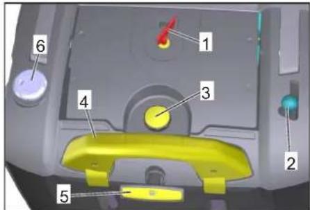
text_image
Labeled diagram of a vehicle interior with numbered components for identification1 Glavna sklopka
2 Poluga za podizanje i spuštanje bočne metle
3 Zaporni vijak poklopca filtra za prašinu
4 Zaporna kuka spremnika nakupljene
prljavštine
5 Čišćenje filtra za prašinu
6 Zasun za mokro/suho usisavanje
Glavna sklopka

text_image
C B A 0 OFF 1| 0/OFF Motor isključen | |
| 1 Motor uključen | |
| A | V a denje ključa |
| B Prikaz smetnje | |
| C Pokazivač napunjenosti akumulatora | |
Vađenje ključa
natural_image
Technical diagram of a cleaning or cleaning machine with labeled components (no text or symbols present)Napomena
text_image
Technical diagram of an automotive battery pack with numbered components and wiring labels→ Stezaljku (crveni kabel) priključite na plus pol (+).
→ Pričvrstite spojni vod na akumulatore.
→ Drugu stezaljku priključite na minus pol (-).
natural_image
Technical line drawing of a mechanical assembly with mounting brackets and a numbered component (no text or symbols)1 Indikator statusa baterije
Indikator statusa baterije prikazuje napredovanje postupka punjenja kada je strujni utikač utaknut:
| Akumulatori se pune treperi zeleno | |
| Akumulatori su napunjeni svijetli zeleno | |
| Smetnja punjača svijetli crveno | |
| Radi se o greški n iz tablice grešaka | treperi crveno n puta sa stankom |
Tablica grešaka:
| 1 Akumulator nije priključen |
| 2 Obrnuti polaritet akumulatora |
| 3 Akumulator je potpuno ispražnjen |
| 4 Problem s karakteristikom punjenja |
| 5 Mrežni utikač je prevruć |
| 6 Hardverska pogreška |
| 7 Greška u komunikaciji (način rada mrežnog utikača) |
natural_image
Line drawing of a cleaning or cleaning machine with four circular components (no text or symbols)text_image
Technical diagram showing a mechanical assembly with an inset image of a device labeled 'LED' and directional arrow indicating motion.→ Otvorite poklopac uređaj.
→ Otpustite protumaticu.
→ Podesite vijak za namještanje.
→ Zategnite protumaticu.
natural_image
Technical illustration of a mechanical device with internal components and an inset showing a close-up of a circular component (no text or symbols present)→ Podignite zasun za grubu prljavštinu, utisnite ležajnu blazinicu te zakrenite valjak za metenje prema naprijed.
→ Izvadite valjak za metenje.
→ Nataknite novi valjak za metenje na pogonski nastavak (lijevo).
→ Na suprotnoj strani uglavite ležajnu blazinicu u provrt ovjesa valjka za metenje.
OPREZ
text_image
R L L + - R +– Uglavljivanjem prilagodne poluge u niži provrt (+) povećavate profil metenja
– Uglavljivanjem prilagodne poluge u viši provrt (-) smanjujete profil metenja
→ Provjerite profil metenja.
Zamjena bočne metle
text_image
Technical diagram showing mechanical assembly with labeled components and a magnified inset of a device component.→ Podesite vijak za namještanje.
→ Zategnite leptir maticu.
Podešavanje dijela za podizanje zasuna za grubu prljavštinu
– Podešavanje je neophodno, ukoliko se zasun za grubu prljavštinu ne može podići dovoljno visoko.
– Kada rezultat metenja postaje lošiji, primjerice zbog habanja prednje gumice, potrebno je malo otpustiti Bowden poteznu žicu.
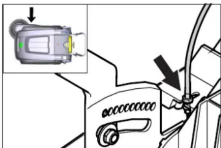
text_image
Diagram showing a device with an inset highlighting a component, likely illustrating a mechanical or electrical assembly.→ Otvorite poklopac uređaja.
→ Otpustite protumaticu.
→ Podesite vijak za namještanje.
→ Zategnite protumaticu.
Podešavanje i zamjena brtvenih letvica
text_image
Technical diagram of a mechanical assembly with numbered components for identification1 Osigurač F1 (50 A)
2 Osigurač F2 (2 A)
3 Relej
4 U t i k a č za punjenje akumulatora
→ Otvorite poklopac uređaja.
→ Zamijenite neispravni osigurač ili relej novim.
■ KM 75/40 W Bp Pack
Osigurač se nalazi na terminalu akumulatora.
Pribor
Mekana bočna metla 6.905-626.0
2006/42/EZ (+2009/127/EZ)
2014/30/EU
2000/14/EZ
Chairman of the Board of Management

S. Reiser
Director Regulatory Affairs & Certification
71364 Winnenden (Germany)
Tel.: +49 7195 14-0
Fax: +49 7195 14-2212
Winnenden, 2021/02/01
Otklanjanje smetnji
text_image
Technical diagram of a mechanical device with numbered parts labeled 1 to 5www.kaercher.com/REACH
Garancija
U svakoj zemlji važe garantni uslovi koje je izdala naša nadležna distributivna organizacija. Eventualne smetnje na priboru za vreme trajanja garancije otklanjamo besplatno, ukoliko je uzrok greška u materijalu ili proizvodnji. U slučaju koji podleže garanciji obratite se sa notvdom o kupovini Vašem prodavcu ili najblizoj ovlašcenoj servisnoj službi.
Simboli u uputstvu za rad
△OPASNOST
Ukazuje na neposredno preteću opasnost koja dovodi do teških telesnih povreda ili smrti.
⚠UPOZORENJE
Ukazuje na eventualno opasnu situaciju koja može dovesti do teških telesnih povreda ili smrti.
OPREZ
Ukazuje na eventualno opasnu situaciju koja može dovesti do lakših telesnih povreda ili izazvati materijalnu štetu.
Simboli na uređaju

Nemojte da metete predmete koji gore ili tinjaju, kao što su npr. cigarette, šibice ili slično.
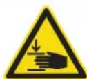
Opasnost od povreda usled prignječenja i posekotina na remenju, bočnim metlama, rezervoarima i potisnim ručkama.
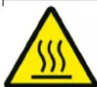
Opasnost od opekotina Izbegavajte kontakt sa ovim površinama tokom rada i kada su u zagrejanom stanju.
Sigurnosne napomene
Sigurnosne napomene vezane za rukovanje
- Pre uporabe proverite da li je uređaj sa svojim radnim komponentama u ispravnom stanju i siguran za rad. Ako stanje nije besprekorno, ne sme se upotrebljavati.
- Pri upotrebi uređaja u opasnim područjima (npr. na benzinskim stanicama) treba se pridržavati odgovarajućih sigurnosnih propisa. Zabranjen je rad u prostorijama u kojima preti opasnost od eksplozija.
- Rukovaoc mora da upotrebljava uređaj u skladu sa njegovom namenom. Mora voditi računa o lokalnim uslovima, a pri radu uređajem mora se paziti na druge osobe, posebno decu.
- Rukovalac se pre početka radova mora uveriti da su sve zaštitne naprave postavljene propisno i da su ispravne.
- Rukovalac uređaja je odgovoran za eventualne slučajeve nesreće kojima su pogođene druge osobe ili njihova imovina.
- Rukovalac mora da nosi usku odeću. Nosite čvrstu obuću i izbegavajte odeću koja nije uz telo.
- Pre pokretanja uređaja prekontrolišite okolinu (npr. ima li dece). Pobrinite se za dobru preglednost!
- Neovlašćeno korišćenje uređaja treba sprečiti izvlačenjem ključa.
- Prilikom napuštanja, uređaj treba osigurati od nenamernog pomeranja.
- Uređaj smeju da koriste samo lica koja su upućena u rukovanje njime i koja mogu dokazati sposobnosti za posluživanje i ovlašćena su za njegovu upotrebu.
- Ovaj uređaj ne smeju da koriste lica (uključujući decu) sa smanjenim fizičkim, senzoričkim ili psihičkim sposobnostima odnosno nedostatkom iskustva i znanja.
– Deca se moraju naggledati kako bi se sprečilo da se igraju s uređajem.
Sigurnosne napomene vezane za vožnju
△Opasnost
Opasnost od povreda!
Opasnost od prevrtanja na prevelikim usponima.
text_image
Exploded view diagram of a cleaning machine with numbered parts for identification1 Zavrtanj za pričvršćivanje potisne ručke (2x)
2 Filter za prašinu
3 Posuda za nakupljenu prljavštinu
4 Zadnja zaptivna letvica (na posudi za prljavštinu)
5 P u n j a č
(samo KM 75/40 W Bp Pack)
6 Akumulatori
(samo KM 75/40 W Bp Pack)
7 Pogonski točkovi
8 B o čna zaptivna letvica
9 Valjak za metenje
10 Prednja zaptivna letvica
11 Zaklopka za grubu prljavštinu
12 Točkić sa pozicionom kočnicom
13 Pričvrsnik bočne metle
14 Bočna metla
15 Bravica poklopca
16 Poklopac uređaja
17 Utikač za punjenje akumulatora (samo KM 75/40 W Bp)
18 Potisna ručica
19 Poluga za vožnju prema napred
20 Poluga za podizanje i spuštanje zaklopke za grubu prljavštinu
Komandno polje

text_image
Labeled diagram of a vehicle interior with numbered components for identification1 Glavni prekidač
2 Poluga za podizanje i spuštanje bočne metle
3 Blokirni zavrtanj poklopca filtera za prašinu
4 Blokirna kuka posude za prljavštinu
5 Čišćenje filtera za prašinu
6 Kapak za mokro/suvo usisavanje
Glavni prekidač

text_image
C B A 0 OFF 1| 0/OFF Motor je isključen | |
| 1 Motor je uključen | |
| A | V a denje ključa |
| B Prikaz smetnje | |
| C Prikaz napunjenosti akumulatora | |
Vađenje ključa
natural_image
Technical diagram of a cleaning or cleaning machine with labeled components (no text or symbols present)Napomena
text_image
Technical diagram of a battery pack with labeled components and wiring connections→ Stezaljku (crveni kabl) priključite na plus pol (+).
→ Pričvrstite spojni vod na akumulatore.
→ Drugu stezaljku priključite na minus pol (-).
Napomena: Proverite da li su polovi i stezaljke akumulatora dovoljno zaštićeni mazivom.
Koristite samo akumulatore sa kapicama. U slučaju da je izgubite, nabavite novu kapicu.
OPREZ
Pre puštanja uređaja u rad napunite akumulatore.
Punjenje akumulatora
⚠️ Opasnost
Opasnost od povreda! Punjač sme da se koristi samo ako strujni kabl nije oštećen. Oštećen strujni kabl mora bez odlaganja da se zameni i to od strane proizvođača, njegove servisne službe ili nekog drugog kvalifikovanog lica.
△OPASNOST
Opasnost od strujnog udara. Obratite pažnju na električne vodove i sigurnosne mere. Punjač koristite samo u suvim i dovoljno prozračenim prostorijama.
Napomena: Vreme punjenja prazne baterije iznosi oko 12 sati.
⚠️Opasnost
Opasnost od povreda! Pridržavajte se propisa o sigurnosti pri radu sa akumulatorom. Pridržavajte se uputstva za upotrebu koje je izdao proizvođač punjača.
Postupak punjenja - KM 75/40 W Bp paket
Pažnja: Punjenje baterija sme da se vrši samo na temperaturi prostorije!
natural_image
Technical line drawing of a mechanical assembly with no visible text or symbols1 Indikator statusa baterije
natural_image
Line drawing of a cleaning or cleaning machine with four circular control symbols around it (no text or labels)text_image
Technical diagram showing a device with an inset image of a connector and directional arrow indicating assembly or operation.→ Otvorite poklopac uređaja.
→ Otpustite kontra-navrtku.
→ Namestite podešavajući zavrtanj.
→ Zategnite kontra-navrtku.
Provera valjka za metenje
→ Zakočite pozicionu kočnicu.
→ Uklonite posudu za prljavštinu.
→ Odstranite trake ili petlje sa valjka za metenje
Zamena valjka za metenje
natural_image
Technical illustration of a mechanical device with a close-up inset showing a pin or knob (no text or symbols present)→ Podignite zaklopku za grubu prljavštinu, utisnite držač ležaja pa zaokrenite valjak za metenje prema napred.
→ Izvadite valjak za metenje.
→ Nataknite novi valjak za metenje na pogonski nastavak (levo).
→ Na naspramnoj strani uglavite držač ležaja u udubljenje nosača valjka za metenje.
OPREZ
Opasnost od oštećenja! Pazite da se čekinje ne zaglave u udubljenje nosača valjka za metenje.
Napomena: Nakon ugradnje novog valjka za metenje mora se iznova podesiti profil metenja.
Provera i podešavanje profila metenja valjka za metenje
→ Uređaj za metenje podignite prema napred i odvezite na ravnu i glatku površinu, koja je vidljivo prekrivena prašinom ili izmrvljenom kredom.
→ Zakočite pozicionu kočnicu.
→ Pustite da se valjak za metenje obrće u trajanju od oko 15-30 sekundi.
→ Uređaj za metenje pognite prema napred i odvezite u stranu.
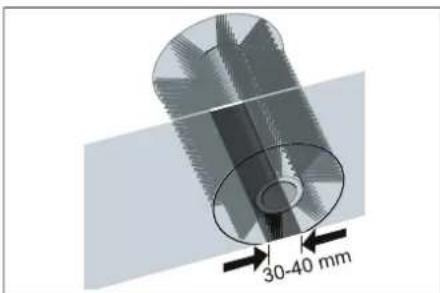
text_image
30-40 mmPometena površina treba da ima oblik pravilnog pravougaonika širine između 30-40 mm.
| Raspon podešavanja (-) 1... | 10 (+) |
| Minimalni profil metenja | 1 |
| Maksimalni profil metenja | 10 |
| Novi valjak za metenje | 1...3 |
Naknadno podešavanje profila metenja:
→ Otvorite poklopac uređaja.
→ Namestite levu i desnu polugu za podešavanje i uglavite ih u istu rupu.
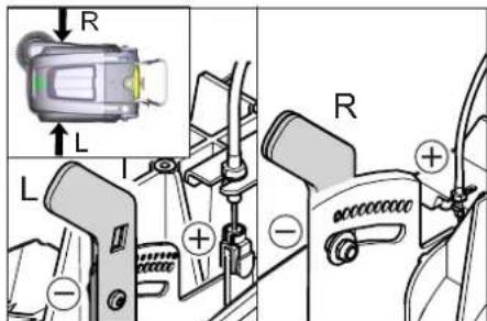
text_image
R L L + - R +text_image
Technical diagram showing a mechanical assembly with labeled components and an inset image of a device with a green indicator light.→ Namestite podešavajući zavrtanj.
→ Zategnite leptir navrtku.
Podešavanje dela za podizanje zaklopke za grubu prljavštinu
text_image
Diagram showing a device with an inset highlighting a component, likely illustrating a mechanical or electrical assembly.→ Otvorite poklopac uređaja.
→ Otpustite kontra-navrtku.
→ Namestite podešavajući zavrtanj.
→ Zategnite kontra-navrtku.
Podešavanje i zamena zaptivnih letvica
Napomena: Pre naginjanja uređaja skinite posudu s nakupljenom prljavštinom, a potisnu ručku zakrenite prema napred. Nemojte da isključujete uređaj pomoću potisne ručke.
■ Prednja zaptivna letvica
→ Otpustite pričvrsnik zaptivne letvice.
→ Podesite ili zamenite zaptivnu letvicu.
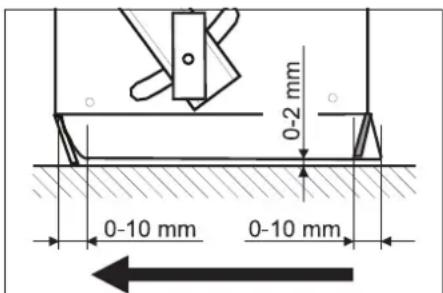
text_image
0-2 mm 0-10 mm 0-10 mm→ Podesite rastojanje zaptivne letvice od poda tako da se ona naginje unazad sa zaustavnim hodom od 0-10 mm.
→ Usmerite zaptivnu letvicu.
→ Zategnite pričvrsnik zaptivne letvice.
■ Zadnja zaptivna letvica
→ Uklonite posudu za prljavštinu.
→ Otpustite pričvrsnik zaptivne letvice.
→ Podesite ili zamenite zaptivnu letvicu.
→ Podesite rastojanje zaptivne letvice od poda tako da se ona naginje unazad sa zaustavnim hodom od 0-10 mm.
→ Zategnite pričvrsnik zaptivne letvice.
■ Bočne zaptivne letvice
→ Otpustite pričvrsnik zaptivne letvice.
→ Podesite ili zamenite zaptivnu letvicu.
→ Za podešavanje rastojanja od podloge podmetnite podlošku debljine najviše 2 mm.
→ Usmerite zaptivnu letvicu.
→ Zategnite pričvrsnik zaptivne letvice.
Zamena filtera za prašinu
⚠UPOZORENJE
Pre početka zamenjivanja filtera za prašinu ispraznite posudu sa nakupljenom prljavštinom. Prilikom radova na filterskom
sklopu nosite masku za zaštitu od prašine. Pridržavajte se propisa o sigurnosti pri radu sa finom prašinom.
OPREZ
Opasnost od oštećenja!
→ Filter za prašinu ne sme da se pere u vodi.
→ Zakočite pozicionu kočnicu.
→ Očistite filter za prašinu.
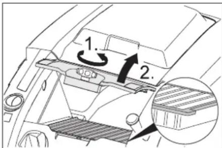
text_image
1. 2.→ Blokirni zavrtanj poklopca filtera za prašinu okrećite suprotno smeru kazaljke sata.
→ Podignite poklopac filtera za prašinu.
→ Zamenite filter za prašinu. Pazite na ispravan položaj ugradnje filtera za prašinu (vidi sliku).
→ Zavijte blokirni zavrtanj do graničnika.
OPREZ
Ako se blokirni zavrtanj ne zavije do graničnika, može doći do oštećenja.
Napomena: Pri ugradnji novog filtera pazite da lamele ostanu neoštećene.
Zamena osigurača/releja
■ KM 75/40 W Bp
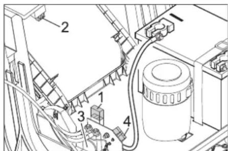
text_image
Technical diagram of a mechanical assembly with numbered components, likely for maintenance or assembly instructions.1 Osigurač F1 (50 A)
2 Osigurač F2 (2 A)
3 Relej
4 U t i k a č za punjenje baterije
→ Otvorite poklopac uređaja.
→ Zamenite neispravan osigurač ili relej.
■ KM 75/40 W Bp Pack
Osigurač se nalazi na priključku baterije.
Pribor
Mekana bočna metla 6.905-626.0
Za finu prašinu na unutrašnjim površinama, vodootporna.
Mekani valjak za metenje 6.906-886.0
Sa prirodnim čekinjama: specijalno za metenje fine prašine na glatkim podovima u zatvorenim prostorijama.
Nije otporan na vodu pa ga nemojte koristiti na abrazivnim površinama!
Tvrdi valjak za metenje 6.906-885.0
Za uklanjanje tvrdokorne prljavštine na spoljašnjim površinama, vodootporna.
| Antistatični valjak za metenje | 6.906-950.0 |
| Za elektrostaticki osetljive površine kao što su tepisi ili veštačka trava | |
| Jedinica za čišćenje tepiha | 2.641-571.0 |
| Sadrži: mrežicu za sakupljanje vlakana, antistatički valjak za čišćenje, trostruki upravljač | |
Izjava o usklađenosti sa propisima EU
Ovim izjavljujemo da ovde opisana mašina po svojoj koncepciji i načinu izrade, sa svim njenim modelima koje smo izneli na tržište, odgovara osnovnim zahtevima dole navedenih propisa Evropske Zajednice o sigurnosti i zdravstvenoj zaštiti. Ova izjava prestaje da važi ako se bez naše saglasnosti na mašini izvedu bilo kakve promene.
Proizvod: Mašina za metenje sa usisavanjem
Tip: 1.049-xxx
2006/42/EZ (+2009/127/EZ)
2014/30/EU
2000/14/EZ
Primenjene uskladene norme:
EN 55012: 2007 + A1: 2009
EN 60335-1
EN 60335-2-72
EN 61000-6-2: 2005
EN 62233: 2008
EN IEC 63000: 2018
Primenjeni nacionalni standardi: ---

H. Jenner
Chairman of the Board of Management

S. Reiser
Director Regulatory Affairs & Certification
71364 Winnenden (Germany)
Tel.: +49 7195 14-0
Fax: +49 7195 14-2212
Winnenden, 2021/02/01
Otklanjanje smetnji
| Smetnja Otklanjanje | |
| Uređaj se ne može pokrenuti | Kontaktni prekidač poklopca je isključio uređaj. Zatvaranje poklopca uređaja |
| Napunite akumulatore. | |
| Provera preopteretnog osigurača | |
| Obavestite Kärcher servisnu službu. | |
| Motor radi, ali se uređaj ne kreće | Podesite Bowden poteznu žicu voznog pogona. |
| Proverite klinasto remenje. | |
| Obavestite Kärcher servisnu službu. | |
| Uređaj se zaustavlja pri savladavanju uspona. | Vozite putem sa manjim usponom. |
| Provera preopteretnog osigurača | |
| Podesite Bowden poteznu žicu voznog pogona. | |
| Proverite klinasto remenje. | |
| Obavestite Kärcher servisnu službu. | |
| Valjak za metenje stoji, prikaz smetnje svetli crveno | Glavni prekidač okrenite na "OFF", proverite da li na četki ima zaglavljenih predmeta. Po potrebi vozite manjim usponom. Ponovo uključite glavni prekidač. Posle četvorostrukog ponavljanja ovog postupka upravljačka jedinica pravi pauzu u trajanju od 2 minuta kako bi se ohladila. Tokom tog vremena se uređaj ne može pokrenuti. |
| Uređaj ne mete kako treba | Proverite pohabanost valjka za metenje i bočnih metli pa ih po potrebi zamenite |
| Proverite ispravnost zaklopke za grubu prljavštinu. | |
| Popustite Bowden poteznu žicu zaklopke za grubu prljavštinu (zavrtanj za podešavanje). | |
| Proverite zategnutost i ispravnost remena, po potrebi ga zamenite. | |
| Naknadno podesite profil metenja. | |
| Zamenite valjak za metenje. | |
| Obavestite Kärcher servisnu službu. | |
| Uređaj diže prašinu | Proverite ispravnost zaklopke za grubu prljavštinu. |
| Popustite Bowden poteznu žicu zaklopke za grubu prljavštinu (zavrtanj za podešavanje). | |
| Proverite, očistite ili zamenite filter za prašinu. Filter za prašinu ne sme da se pere u vodi. | |
| Ispraznite posudu za nakupljenu prljavštinu | |
| Zamenite zaptivni profil na posudi za prljavštinu. | |
| Proverite zaptivku na filteru za prašinu. | |
| Proverite pohabanost zaptivnih letvica, po potrebi ih podesite ili zamenite. | |
| Loše metenje po ivicama | Podesite deo za spuštanje bočne metle. |
| Zamenite bočnu metlu | |
| Spustite bočnu metlu. | |
| Proverite pogonski remen bočne metle. | |
| Obavestite Kärcher servisnu službu. | |
| Deo za podizanje bočne metle ne radi. | Proverite Bowden poteznu žicu za podizanje bočne metle. |
| Obavestite Kärcher servisnu službu. | |
| Novi valjak za metenje se tare o posudu za prljavštinu. | Iznova podesite profil metenja. U tu svrhu uglavite o be poluge za podešavanje u odgovarajuću višu rupu (1...3). |
Tehnički podaci
| KM 75/40 W Bp KM 75/40 W Bp Pack | |||
| Podaci uređaja | |||
| Dužina x širina x visina (potisna ručka rasklopljena) | mm | 1430 x 750 x 1190 | 1430 x 750 x 1190 |
| Dužina x širina x visina (potisna ručka sklopljena) | mm | 1160 x 750 x 930 | 1160 x 750 x 930 |
| Težina (bez akumulatora) kg 79 79 | |||
| Težina (s akumulatorima) kg 125 125 | |||
| Dozvoljena ukupna težina kg 205 205 | |||
| Brzina vožnje i metenja km/h 4,5 4,5 | |||
| Savladavanje uspona (maks.) | % | 12 12 | |
| Prečnik valjka za metenje mm 265 265 | |||
| Prečnik bočnih metli | mm | 410 | 410 |
| Maks. površinski učinak | m3/h | 3400 | 3400 |
| Radna širina bez bočne metle | mm | 550 | 550 |
| Radna širina sa bočnom metlom | mm | 750 | 750 |
| Zapremina posude za prljavštinu | l | 40 40 | |
| Stepen zaštite, zaštićeno od kapajuće vode | -- | IPX 3 | IPX 3 |
| Motor | |||
| Tip | -- | Motor jednosmerne struje sa permanentnim magnetomSmer okretanja udesno | |
| Napon | V | 24 24 | |
| Nominalna jačina struje | A | 22 | 22 |
| Nominalna snaga | W | 400 400 | |
| Broj obrtaja | 1/min | 2750 | 2750 |
| Stepen zaštite | -- | IP 20 | IP 20 |
| Akumulator | |||
| Tip | -- | -- | 2x 12 V GiV |
| Kapacitet | Ah | -- | 60 (5h) |
| Težina | kg -- | 23 | |
| Trajanje punjenja potpuno ispražnjenog akumulatora h -- | 12 | ||
| Trajanje rada nakon višekratnog punjenja | h | -- | ca. 1,5-2 |
| Punjač | |||
| Napon el. mreže | V~ | -- | 230 |
| Izlazni napon | V | -- | 24 |
| Struja punjenja | A | -- | 10 |
| Frekvencija mreže | Hz | -- | 50/60 |
| Električna zaštita | |||
| Centralna | A | 50 50 | |
| Osigurač upravljačke jedinice | A | 2 | -- |
| Zaštita od potpunog pražnjenja akumulatora | -- | preko releja | preko releja |
| Punjač | --- | T4A / 250 V AC | |
| Filterski i usisni sistem | |||
| Površina filtera za finu prašinu | m2 | 1,8 1,8 | |
| Kategorija primene filtra za prašinu koja ne škodi zdravlju | -- | L | L |
| Nominalni podpritisak usisnog sistema | mbar | 5 | 5 |
| Nominalni zapreminski protok usisnog sistema | l/s | 45 45 | |
| Okolni uslovi | |||
| Radna temperatura | °C | -5 do +40 | -5 do +40 |
| Temperatura punjenja | --- | Temperatura prostorije | |
| Vlažnost vazduha, bez stvaranja kondenzata | % | 0 - 90 | 0 - 90 |
| Izračunate vrednosti prema EN 60335-2-72 | |||
| Nivo zvučnog pritiska LpA | dB(A) | 71 71 | |
| Nepouzdanost KpA | dB(A) | 3 | 3 |
| Nivo zvučne snage LwA + nepouzdanost KwA | dB(A) | 88 88 | |
| Nepouzdanost KwA | 2 | 2 | |
| Vrednost vibracije na ruci | m/s2 | 3,7 3,7 | |
| Nepouzdanost K | m/s2 | 0,2 0,2 | |
Pridržano pravo na tehničke promene.
text_image
Technical diagram of a mechanical device with numbered parts labeled 1 to 5www.kaercher.com/REACH
Гаранция
text_image
Exploded view diagram of a cleaning machine with numbered parts for identificationtext_image
Labeled diagram of a vehicle interior with numbered components for identificationnatural_image
Technical line drawing of a cleaning or cleaning machine with labeled components (no text or symbols)Указание
text_image
Technical diagram of an automotive battery pack with labeled components and wiring connectionsnatural_image
Technical line drawing of a mechanical assembly with no visible text or symbolsnatural_image
Line drawing of a cleaning or cleaning machine with four circular components, no text or symbols present.text_image
Technical diagram showing a device connection with an inset image of a sensor device and directional arrows indicating assembly or operation.text_image
Technical diagram of a mechanical assembly with numbered components, likely a valve or pump assembly.
Chairman of the Board of Management

Director Regulatory Affairs & Certification
71364 Winnenden (Germany)
Tel.: +49 7195 14-0
Fax: +49 7195 14-2212
Winnenden, 2021/02/01
text_image
Technical diagram of a mechanical harvester with numbered parts labeled 1 through 5www.kaercher.com/REACH
Garantii
text_image
Exploded view diagram of a cleaning machine with numbered parts for identificationtext_image
Labeled diagram of a vehicle interior with numbered components for identificationnatural_image
Technical line drawing of a cleaning or cleaning device with labeled components (no text or symbols present)Märkus
KM 75/40 W Bp Pack puhul on akud ja laa-dur juba integreeritud.
→ Avage seadme kate.
→ Asetage akud mootori alusele.
→ Kinnitage akud vastavate holderihma-dega.
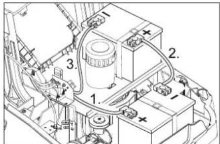
text_image
Technical diagram of an electrical device with numbered components and wiring labelsnatural_image
Technical line drawing of a mechanical assembly with gears and shafts (no text or symbols)1 Aku oleku näidik
natural_image
Line drawing of a cleaning or cleaning machine with four circular components, no text or symbols presenttext_image
Technical diagram showing a device with an inset image of a sensor or connector, highlighting a component with an arrow.→ Avage seadme kate.
→ Vabastage kontramutter.
→ Reguleerige seadekruvi.
→ Keerake kontramutter kinni.
natural_image
Technical illustration of a mechanical device with internal components and a close-up inset showing a pin (no text or symbols present)text_image
R L L + - R +text_image
Technical diagram showing mechanical assembly with labeled components and a magnified inset of a device component.text_image
Diagram showing a car interior with a highlighted component and an arrow indicating a directional change or adjustment.→ Avage seadme kate.
→ Vabastage kontramutter.
→ Reguleerige seadekruvi.
→ Keerake kontramutter kinni.
text_image
Technical diagram of a mechanical assembly with numbered components and labeled parts1 Kaitse F1 (50 A)
2 Kaitse F2 (2 A)
3 Relee
4 Akulaadija pistik
H. Jenner
Chairman of the Board of Management
S. Reiser
Director Regulatory Affairs & Certification
71364 Winnenden (Germany)
Tel.: +49 7195 14-0
Fax: +49 7195 14-2212
Winnenden, 2021/02/01
Abi häirete korral
www.kaercher.com/REACH
Garantija
natural_image
Technical line drawing of a cleaning or cleaning machine with labeled components (no text or symbols)Norāde
text_image
Technical diagram of an automotive battery pack with numbered components and wiring labelsnatural_image
Technical line drawing of a mechanical assembly with mounting brackets and a numbered component (no text or symbols)1 Akumulatora stāvokla indikators
natural_image
Line drawing of a cleaning or cleaning machine with four circular components, no text or symbols presenttext_image
Technical diagram showing a mechanical assembly with an inset image of a device labeled 'LED' and directional arrows indicating movement or force.natural_image
Technical line drawing of a mechanical device with internal components and an inset showing a close-up detail (no text or symbols)text_image
R L L + - R +text_image
Technical diagram showing a mechanical assembly with labeled components and an inset image of a device emitting light.text_image
Diagram showing a car's seatbelt switch mechanism with an inset image of the device and directional arrow indicating rotation.text_image
Technical diagram of an industrial machine with numbered components for identificationChairman of the Board of Management
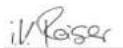
S. Reiser
Director Regulatory Affairs & Certification
71364 Winnenden (Germany)
Tel.: +49 7195 14-0
Fax: +49 7195 14-2212
Winnenden, 2021/02/01
text_image
Technical diagram of a mechanical harvester with numbered parts labeled 1 to 5www.kaercher.com/REACH
Garantija
text_image
Exploded view diagram of a cleaning machine with numbered parts for identificationtext_image
Labeled diagram of a vehicle interior with numbered components for identificationnatural_image
Technical line drawing of a cleaning or cleaning machine with labeled components (no text or symbols present)Pastaba
text_image
Technical diagram of an automotive battery pack with numbered components and wiring labelsnatural_image
Technical line drawing of a mechanical assembly with mounting brackets and a numbered component (no text or symbols)natural_image
Line drawing of a cleaning or cleaning machine with four circular components, no text or symbols presenttext_image
Technical diagram showing a device with an inset image of a sensor or connector, highlighting a component with an arrow.natural_image
Technical illustration of a mechanical device with a magnified inset showing a close-up detail (no text or symbols)text_image
R L L + - R +text_image
Technical diagram showing a mechanical assembly with labeled components and an inset image of a device emitting light.text_image
Diagram showing a vehicle's seatbelt switch with an inset image of the device and its warning symbol.text_image
Technical diagram of an industrial machine with numbered components and wiring labels1 Saugiklis F1 (50 A)
2 Saugiklis F2 (2 A)
3 R e l è
4 Bateriju jkroviklio kištukas
Chairman of the Board of Management

S. Reiser
Director Regulatory Affairs & Certification
71364 Winnenden (Germany)
Tel.: +49 7195 14-0
Fax: +49 7195 14-2212
Winnenden, 2021/02/01
text_image
Technical diagram of a mechanical device with numbered parts labeled 1 to 5www.kaercher.com/REACH
Гарантія
text_image
Exploded view diagram of a cleaning machine with numbered parts for identificationtext_image
Labeled diagram of a vehicle interior with numbered components for identificationnatural_image
Technical line drawing of a cleaning or cleaning machine with labeled components (no text or symbols present)Вказівка
text_image
Technical diagram of a mechanical or electrical component with numbered parts and labeled connectorsnatural_image
Technical line drawing of a mechanical assembly with no visible text or symbolsnatural_image
Line drawing of a cleaning or cleaning machine with four circular warning symbols around it (no text or labels)text_image
Technical diagram showing a device with an inset image of a sensor or connector, highlighting a component with an arrow.natural_image
Technical illustration of a mechanical device with internal components and a close-up inset showing a detail (no text or symbols)text_image
R L L + - R + -text_image
Technical diagram showing mechanical assembly with labeled components and a magnified inset of a device component.text_image
Diagram showing a device with an orange sensor and a black arrow pointing to a component, likely illustrating a mechanical or electrical assembly.text_image
Diagram showing a mechanical component with labeled parts and directional arrows, including a magnified inset of a textured surface.text_image
Technical diagram of a mechanical or electrical component with numbered parts labeled 1 to 4
H. Jenner
Chairman of the Board of Management

S. Reiser
Director Regulatory Affairs & Certification
71364 Winnenden (Germany)
Tel.: +49 7195 14-0
Fax: +49 7195 14-2212
Winnenden, 2021/02/01
text_image
Technical diagram of a mechanical harvester with numbered parts labeled 1 through 5text_image
Exploded view diagram of a cleaning machine with numbered parts for identification and assembly reference.text_image
Labeled diagram of a mechanical device interior with numbered componentsnatural_image
Technical illustration of a cleaning or cleaning device with labeled components (no text or symbols present)Ескертпе
text_image
Technical diagram of an electronic device with labeled components and wiring connectionsnatural_image
Technical line drawing of a mechanical assembly with mounting brackets and a numbered component (no text or symbols)natural_image
Line drawing of a cleaning or cleaning machine with four circular components (no text or symbols)text_image
Technical diagram showing a device with an inset image of a sensor or camera component and directional arrows indicating assembly or operation.natural_image
Technical line drawing of a mechanical device with a magnified inset showing a detail (no text or symbols present)text_image
R L L + - R + -text_image
Technical diagram showing a mechanical assembly with labeled components and an inset image of a device with a warning symbol.text_image
Diagram showing a car interior with a highlighted device and directional arrow, likely illustrating a mechanical or safety concept.text_image
Technical diagram of a mechanical assembly with numbered components, likely a pump or fan unit.
Chairman of the Board of Management

S. Reiser
Director Regulatory Affairs & Certification
text_image
Exploded view diagram of a cleaning or cleaning machine with numbered parts and an inset detail showing internal components.text_image
Labeled diagram of a mechanical device interior with numbered componentsnatural_image
Technical diagram of a cleaning or cleaning machine with labeled components (no text or symbols present)提示
text_image
Technical diagram of an electrical or mechanical device with numbered components and wiring connectionsnatural_image
Technical line drawing of a mechanical assembly with mounting holes and a numbered component (no text or symbols)1 电池状态指示灯
natural_image
Line drawing of a cleaning or cleaning machine with four circular components (no text or symbols)text_image
Technical diagram showing a mechanical assembly with an inset image of a device labeled 'LED' and directional arrows indicating movement or force.natural_image
Technical illustration of a mechanical device with internal components and an inset close-up showing a pin (no text or symbols present)text_image
R L L + - R + -text_image
Technical diagram showing mechanical assembly with labeled components and a magnified inset of a device component.→ 调节调节螺钉。
→ 拧紧蝶形螺母。
调节粗污物挡板抬升高度
text_image
Diagram showing a mechanical component with an inset close-up highlighting a highlighted component and directional arrow indicating movement.text_image
Technical diagram of a mechanical assembly with numbered components, likely a pump or filter unit.Chairman of the Board of Management

S. Reiser
Director Regulatory Affairs & Certification
文档全权代表:
S. Reiser
Alfred Kärcher SE & Co. KG
Winnenden, 2021/02/01
故障排除帮助
text_image
Technical diagram of a mechanical harvester with numbered parts labeled 1 through 5text_image
Exploded view diagram of a cleaning or cleaning machine with numbered parts and an inset detail showing internal components.text_image
Labeled diagram of a mechanical device interior with numbered componentsnatural_image
Technical illustration of a cleaning or cleaning device with labeled components (no text or symbols present)注
text_image
Technical diagram of an automotive battery system with labeled components and wiring connectionsnatural_image
Technical line drawing of a mechanical assembly with no visible text or symbols1 バッテリー残量表示
natural_image
Line drawing of a cleaning or cleaning machine with four circular warning symbols around it (no text or labels)1 ブッシュハンドル上部の固定箇所
2 本体カバーの下の固定箇所
text_image
Technical diagram showing a mechanical assembly with an inset image of a device component and directional arrow indicating motion.natural_image
Technical illustration of a mechanical device with a close-up inset showing a pin inserted into a component (no text or symbols present)text_image
R L L + - R +text_image
Technical diagram showing mechanical assembly with labeled components and a magnified inset of a device component.text_image
Diagram showing a car interior with a highlighted component and directional arrow, likely illustrating a vehicle or safety inspection.text_image
Technical diagram of a mechanical assembly with numbered components, likely a pump or filter system.1 ヒューズ F1 (50 A)
2 ヒューズ F2 (2 A)
3 リレー
4 バッテリー充電プラグ
→ 本体カバーを開きます。

Chairman of the Board of Management

S. Reiser
Director Regulatory Affairs & Certification
文書の全権委員:
S. Reiser
Alfred Kärcher SE & Co. KG
71364 Winnenden (Germany)
電話:+49 7195 14-0
Fax: +49 7195 14-2212
Winnenden、2021年2月1日
トラブル発生時のサポート
text_image
Technical diagram of an industrial machine with numbered components for identificationtext_image
Technical diagram showing mechanical assembly with labeled components and a magnified inset of a device component.تعدل مسمار الضبط.
text_image
Diagram showing a device's internal components with an inset highlighting a highlighted component and directional arrow.→ افتح غطاء الجهاز.
text_image
R L L + - R +text_image
Technical diagram showing mechanical assembly with labeled components and a magnified inset highlighting a component with green indicator light.→ افتح غطاء الجهاز.
natural_image
Technical illustration of a mechanical device with internal components and a close-up inset showing a pin (no text or symbols present)natural_image
Line drawing of a cleaning or cleaning machine with four circular components (no text or symbols)natural_image
Technical line drawing of a mechanical assembly with labeled parts (no text or symbols present)1 مؤشر حالة الطارية
natural_image
Technical line drawing of a cleaning or cleaning device with multiple components and a brush (no text or symbols visible)ملحوظة
text_image
Technical diagram of an electrical or mechanical device with numbered components and labeled partstext_image
Exploded view diagram of a cleaning machine with numbered parts for identification and assembly reference.المفتاح الرئيسي
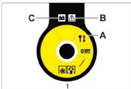
text_image
C B A 0 OFF 1text_image
Labeled diagram of a mechanical device interior with numbered components1 المفتاح الرئيس
text_image
Technical diagram of a mechanical device with numbered parts labeled 1 to 5www.kaercher.com/REACH
natural_image
Black silhouette of a hand giving a thumbs-up gesture (no text or symbols)THANK YOU!
MERCI! DANKE! iGRACIAS!

Register your product and benefit from many advantages.
www.kaercher.com/welcome


Rate your product and tell us your opinion.
natural_image
Icon showing a gear and wrench inside a square frame (no text or symbols)www.kaercher.com/dealersearch
Alfred Kärcher SE & Co. KG
Alfred-Kärcher-Str. 28-40
71364 Winnenden (Germany)
Tel.: +49 7195 14-0
Fax: +49 7195 14-2212