
RS PRO P3 S - Lamp STEINEL - Free user manual and instructions
Find the device manual for free RS PRO P3 S STEINEL in PDF.
| Product type | Detection porthole with emergency lighting |
| Brand | Steinel |
| Model | RS PRO P3 S |
| Dimensions (diameter x height) | 400 × 142 mm |
| Supply voltage | 220-240 V, 50/60 Hz |
| Power consumption | 18,4 W (neutral white / warm white) |
| Luminous flux | 2 188 lm (neutral white) / 2 072 lm (warm white) |
| Color temperature | 4 000 K (neutral white) / 3 000 K (warm white) |
| Protection rating | IP54 |
| Protection class | II |
| Detector type | High frequency (5.8 GHz), range 1-8 m, angle 360° |
| Time delay | From 5 seconds to 15 minutes |
| Orientation lighting | 10% of the light output |
| Trigger threshold | From 2 to 2,000 lux |
| Emergency lighting function | Yes, 3 hours runtime (NiMH AAA batteries) |
| Maintenance and cleaning | Clean with a damp cloth without detergent. No maintenance required. |
| Safety | Disconnect power before servicing. Installation by a professional. |
| Spare parts | Replacement batteries for emergency module (ref. EAN 4007841 006457) |
| Repairability | Repairs exclusively by a specialized workshop. Light source not replaceable. |
| Warranty | 5 years (excluding replaceable sources) |
Frequently Asked Questions - RS PRO P3 S STEINEL
User questions about RS PRO P3 S STEINEL
0 question about this device. Answer the ones you know or ask your own.
Ask a new question about this device
Download the instructions for your Lamp in PDF format for free! Find your manual RS PRO P3 S - STEINEL and take your electronic device back in hand. On this page are published all the documents necessary for the use of your device. RS PRO P3 S by STEINEL.
USER MANUAL RS PRO P3 S STEINEL
natural_image
Three transparent, rounded objects of varying sizes and shading against a white background (no text or symbols)RS PRO LED P1 S
RS PRO LED P2 S
RS PRO LED P3 S
RS PRO LED P1 S FLAT
RS PRO LED P2 S FLAT

GB .....15 Follow written instructions!
radar
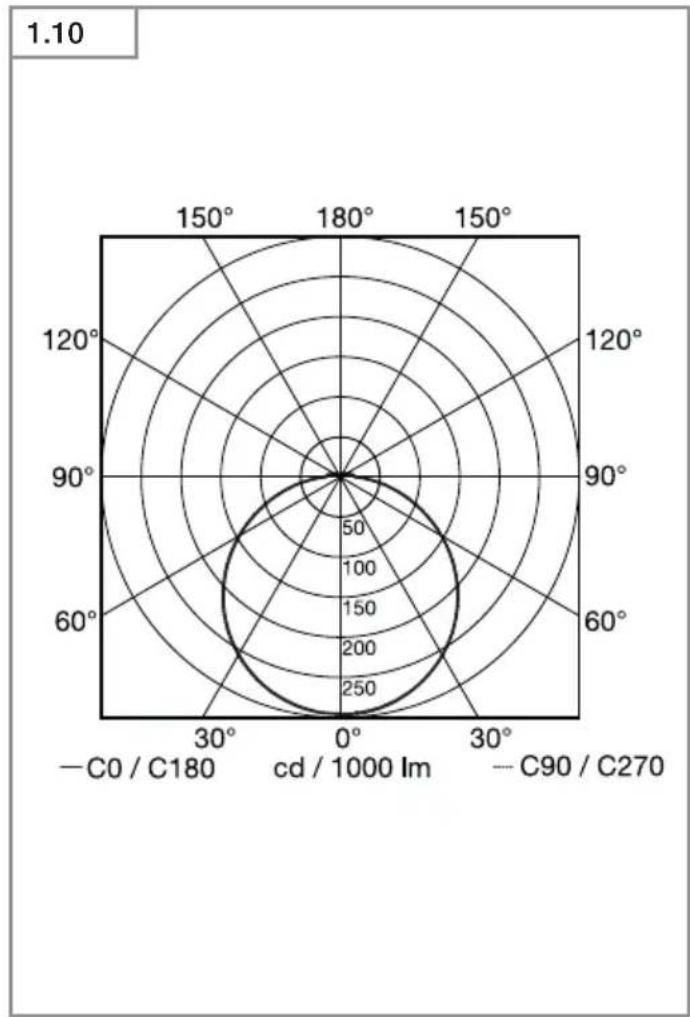
| Angle | Value | |-------|-------| | 0° | 250 | | 30° | 200 | | 60° | 150 | | 90° | 100 | | 120° | 50 | | 150° | 0 | | 180° | 0 | | 210° | 0 | | 240° | 0 | | 270° | 0 | | 300° | 0 | | 330° | 0 | | 360° | 0 |1.1
2.2
natural_image
Diagram showing a device inside a circular housing with bidirectional arrows indicating rotation or signal flow (no text or symbols present)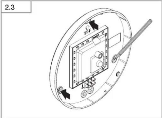
2.1
natural_image
Diagram showing room layout with seating, fixtures, and directional indicators (no text or labels)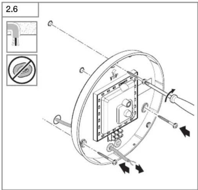
natural_image
Diagram of a battery pack with two cylindrical batteries and an open casing, showing internal components and a black arrow indicating a component (no text or symbols present)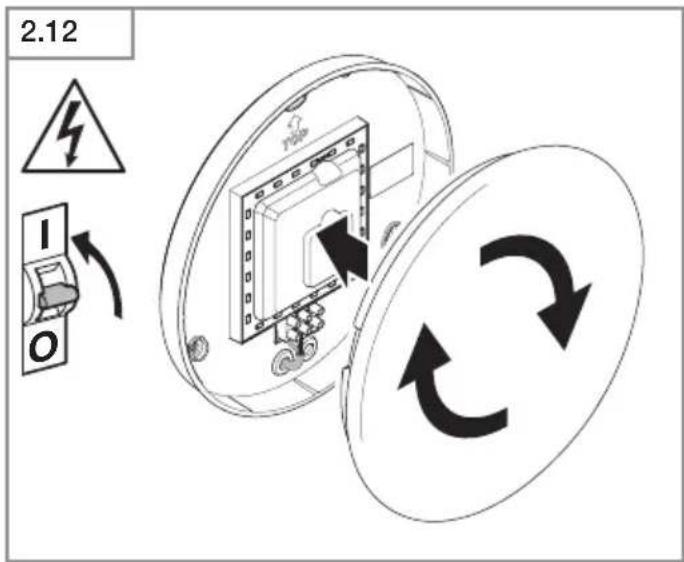
flowchart
graph LR
    A["Sun"] --> B["+"]
    C["Moon"] --> D["-"]
    E["Off"] --> F["+"]
    style A fill:#f9f,stroke:#333
    style B fill:#ccf,stroke:#333
    style C fill:#cfc,stroke:#333
    style D fill:#fcc,stroke:#333
    style E fill:#cff,stroke:#333
    style F fill:#ffc,stroke:#333
DE
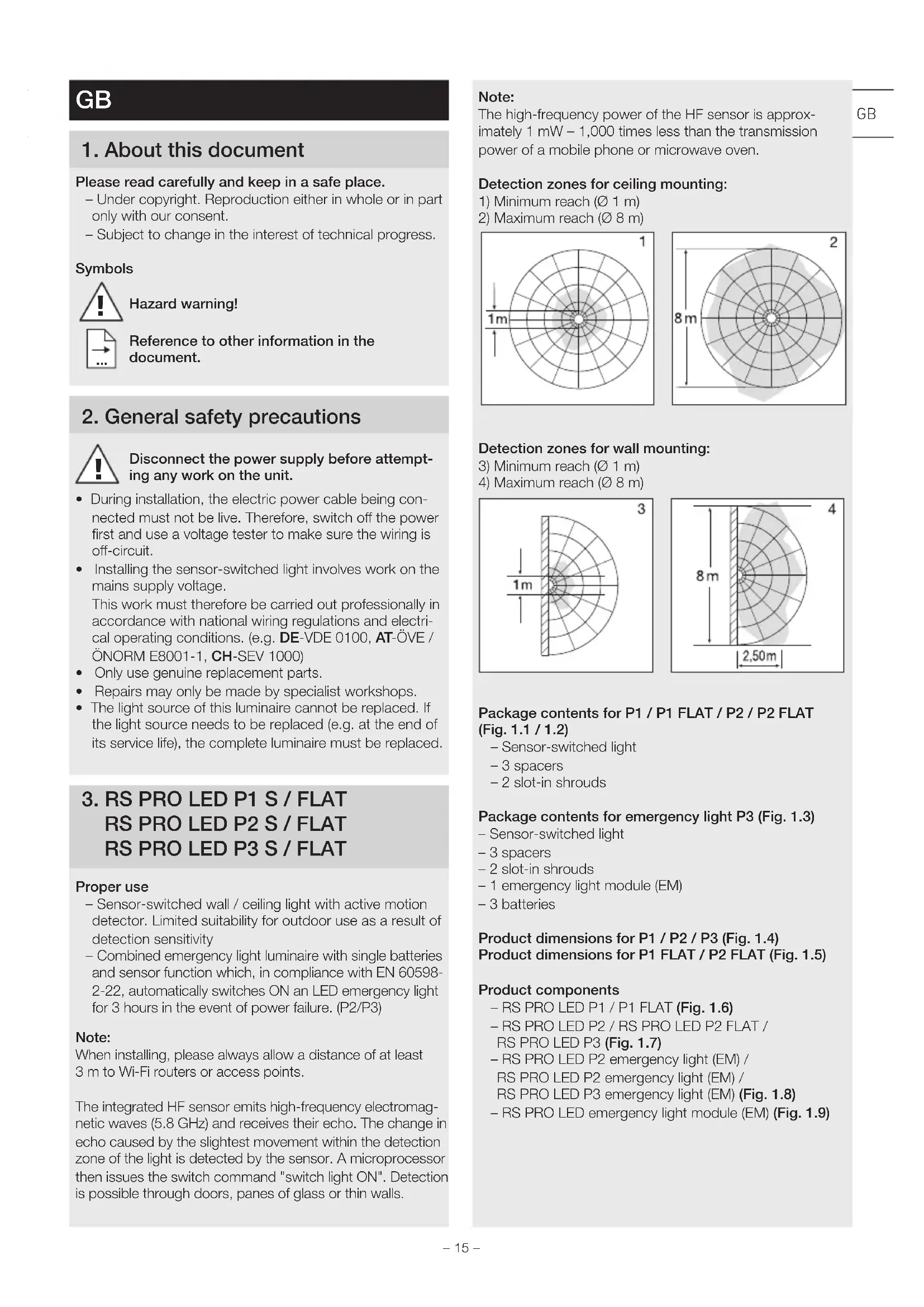
Please read carefully and keep in a safe place.
- Under copyright. Reproduction either in whole or in part only with our consent.
- Subject to change in the interest of technical progress.
Symbols

Hazard warning!

Reference to other information in the document.
2. General safety precautions

Disconnect the power supply before attempting any work on the unit.
- During installation, the electric power cable being connected must not be live. Therefore, switch off the power first and use a voltage tester to make sure the wiring is off-circuit.
- Installing the sensor-switched light involves work on the mains supply voltage.
This work must therefore be carried out professionally in accordance with national wiring regulations and electrical operating conditions. (e.g. DE-VDE 0100, AT-ÖVE / ÖNORM E8001-1, CH-SEV 1000)
- Only use genuine replacement parts.
• Repairs may only be made by specialist workshops. - The light source of this luminaire cannot be replaced. If the light source needs to be replaced (e.g. at the end of its service life), the complete luminaire must be replaced.
3. RS PRO LED P1 S / FLAT RS PRO LED P2 S / FLAT RS PRO LED P3 S / FLAT
Proper use
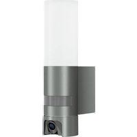
– Sensor-switched wall / ceiling light with active motion detector. Limited suitability for outdoor use as a result of detection sensitivity
- Combined emergency light luminaire with single batteries and sensor function which, in compliance with EN 60598-2-22, automatically switches ON an LED emergency light for 3 hours in the event of power failure. (P2/P3)
Note:
When installing, please always allow a distance of at least 3 m to Wi-Fi routers or access points.
The integrated HF sensor emits high-frequency electromagnetic waves (5.8 GHz) and receives their echo. The change in echo caused by the slightest movement within the detection zone of the light is detected by the sensor. A microprocessor then issues the switch command "switch light ON". Detection is possible through doors, panes of glass or thin walls.
Note:
The high-frequency power of the HF sensor is approximately 1 mW – 1,000 times less than the transmission power of a mobile phone or microwave oven.
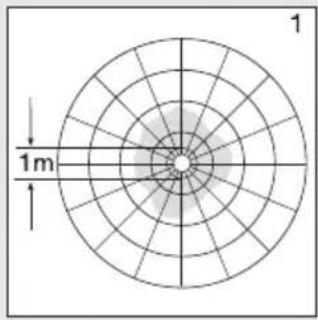
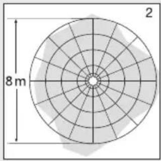
Detection zones for ceiling mounting:
1) Minimum reach (∅ 1 m)
2) Maximum reach ( 8 m)
Detection zones for wall mounting:
- Sensor-switched light
- 3 spacers
- 2 slot-in shrouds
Package contents for emergency light P3 (Fig. 1.3)
- Sensor-switched light
- 3 spacers
- 2 slot-in shrouds
- 1 emergency light module (EM)
-3 batteries
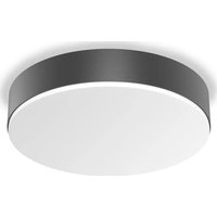
Product dimensions for P1 / P2 / P3 (Fig. 1.4)
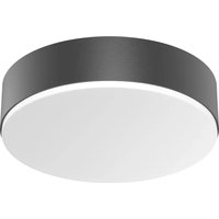
Product dimensions for P1 FLAT / P2 FLAT (Fig. 1.5)
Product components
- RS PRO LED P1 / P1 FLAT (Fig. 1.6)
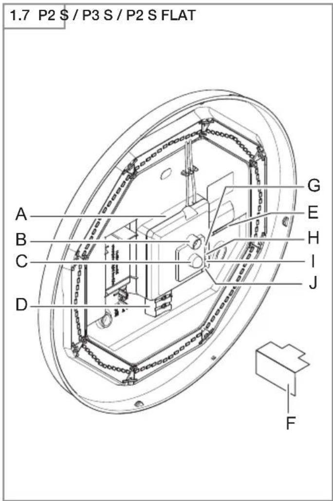
- RS PRO LED P2 / RS PRO LED P2 FLAT / RS PRO LED P3 (Fig. 1.7)
- RS PRO LED P2 emergency light (EM) /
RS PRO LED P2 emergency light (EM) /
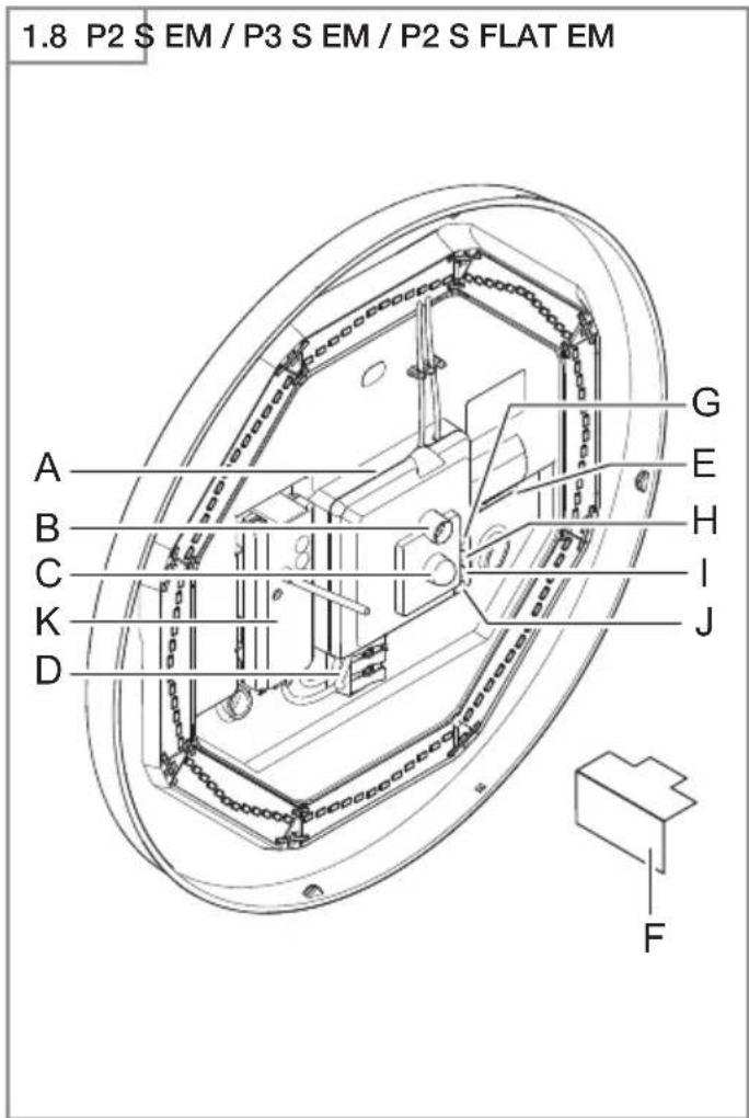
RS PRO LED P3 emergency light (EM) (Fig. 1.8)
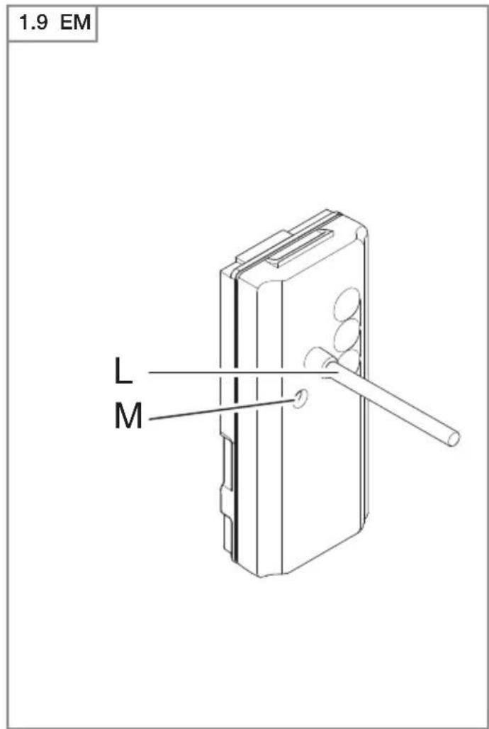
- RS PRO LED emergency light module (EM) (Fig. 1.9)
A Electronics enclosure
B Light sensor
C HF sensor
D Connecting terminal
E Sealing plug
F Slot-in shroud
G Basic light level setting
H Time setting
I Reach adjustment
J Twilight setting
K Emergency light module (optional)
L Status LED
M "test" button
Luminous intensity distribution (Fig. 1.10)
4. Electrical connection
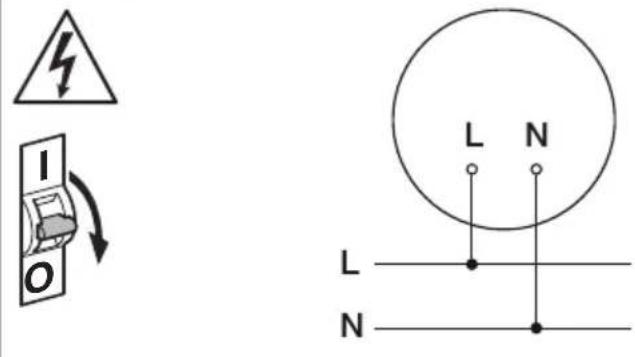
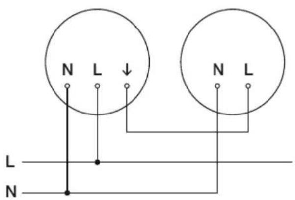
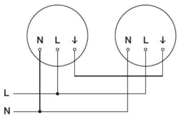
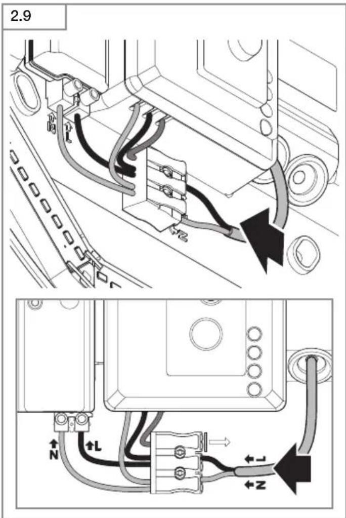
Wiring diagram (Fig. 1.1)
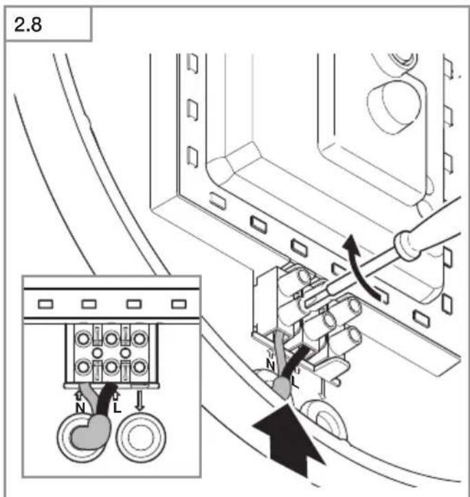
The mains power supply lead is a 3-core cable:
L = phase conductor (usually black, brown or grey)
N = neutral conductor (usually blue)
PE = protective-earth conductor (green / yellow)
↓ = switched phase conductor (usually black, brown or grey)
If you are in any doubt, identify the conductors using a voltage tester; then disconnect from the power supply again.
Connect phase (L), (↓) as well as the neutral conductor (N) to the connecting terminal.
Important:
Incorrectly wired connections will produce a short circuit later on in the product or your fuse box. In this case, you must identify the individual conductors once again and reconnect them. A mains power switch for turning the unit ON and OFF may of course be installed in the mains supply lead (in applications without emergency light module).
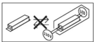
Connection to a dimmer will result in damage to the sensor-switched light.
Note:
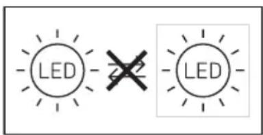
Do not make direct contact with the LED.
Note: The light source in this light cannot be replaced. If the light source needs to be replaced (e.g. at the end of its service life), the complete light must be replaced.
5. Mounting
- Check all components for damage.
- Do not use the product if it is damaged.
- When installing the sensor-switched light, make sure the installation site is not exposed to vibration.
- Select an appropriate mounting location, taking the reach and motion detection into consideration.
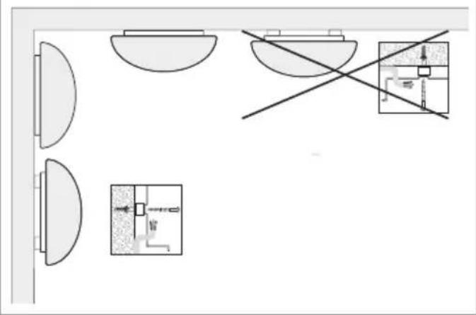
- Not suitable for ceiling mounting with surface-mounted power supply lead. (Fig. 2.1)
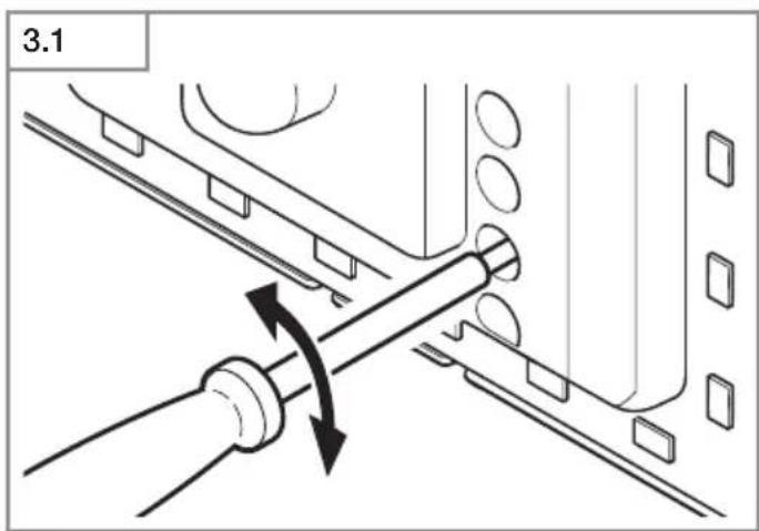
Installation procedure
- Switch OFF power supply (Fig. 1.1).
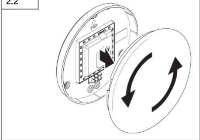
- Detach shade from enclosure (Fig. 2.2).
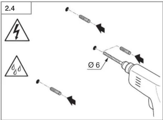
• Mark drill holes (Fig. 2.3). - Drill holes and insert wall plugs (Fig. 2.4).
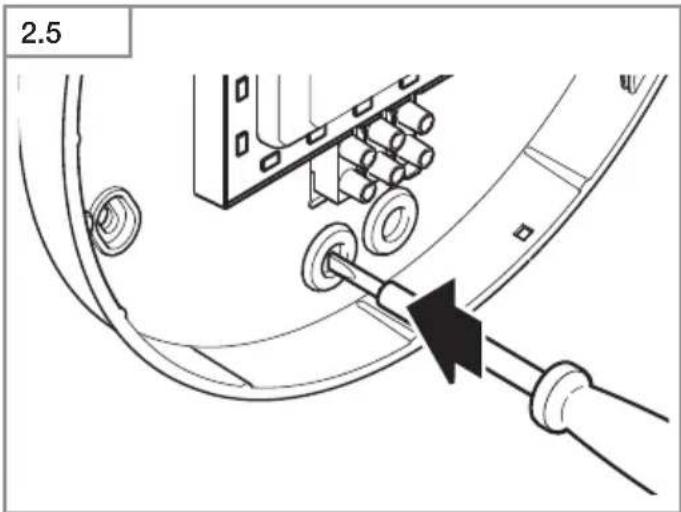
- Pierce sealing plug for power supply lead (Fig. 2.5).
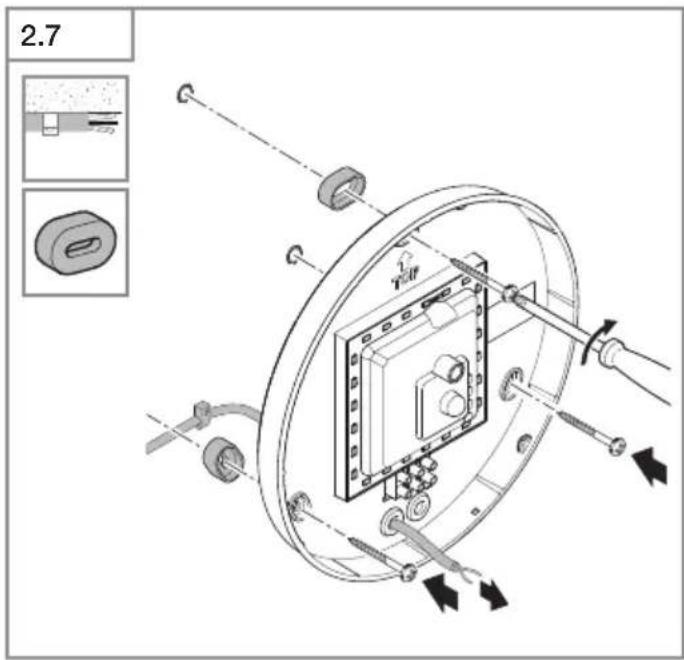
• Installation with concealed power supply lead (Fig. 2.6). - Installation with surface-mounted power supply lead (Fig. 2.7).
- Connect conductors (Fig. 2.8-2.9).
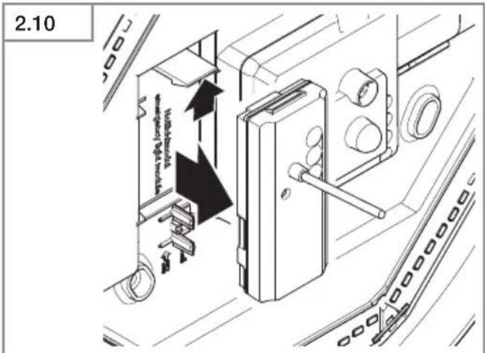
- Remove emergency light module (Fig. 2.10).
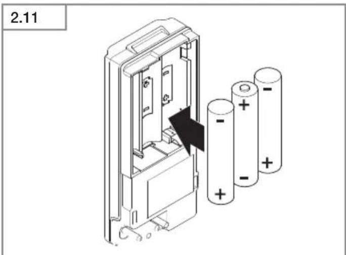
- Replace batteries (Fig. 2.11).
- Switch ON power supply (Fig. 2.12).
• Make settings → "6. Function".
• Fit shade (Fig. 2.12).
6. Function
Factory settings
– Twilight setting 2,000 lux
- Reach setting 8 m
– Time setting 5 seconds
- Basic light level function Off
The sensor-switched light can be put into service after mounting the enclosure and connecting to the mains power supply. When putting the light into operation manually at the light switch, it will switch OFF after 10 seconds for the calibration phase and is then activated for sensor mode. It is not necessary to operate the light switch a second time.
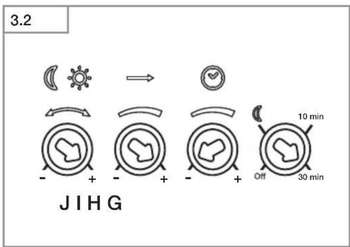
Control dials (Fig. 3.2)
Twilight setting (response threshold) (J)
The chosen response threshold can be infinitely varied from approx. 2 to 2,000 lux.
- Control dial set to + = daylight mode (depending on ambient brightness)
- Control dial set to - = twilight mode (approx. 2 lux)
The control dial must be turned to + when adjusting the detection zone and performing the functional test in daylight.
Reach setting (sensitivity) (I)
Reach is the term used to describe the diameter of the more or less circular detection zone produced on the ground after mounting the sensor-switched light at a height of 2.5 m.
- Control dial + = max. reach of 8 m
- Control dial - = min. reach of 1 m
Time setting (stay-ON time) (H)
The light's ON time can be set to any period from approx. 5 seconds to a maximum of 15 minutes. Any movement detected before this time elapses will restart the timer.
- Control dial set to + = longest time, approx. 15 minutes
- Control dial set to - = approx. 5 seconds
Note:
After the light switches OFF, it takes approx. 1 second before it is able to start detecting movement again. The light will only switch ON in response to movement once this period has elapsed.
The shortest time setting is recommended when adjusting the detection zone and performing the functional test.
Basic light level function (G)
The basic light level function provides illumination at approx. 10 % light output when the brightness setting is reached. Movement in the detection zone switches the light ON at 100 % brightness for the time selected. Light switches OFF completely after the selected time has elapsed. If the brightness setting has not yet been reached, basic light is switched back ON again.
- Control dial set to = basic light ON
- Control dial set to Off = basic light OFF
- Control dial set to 10 min = basic light for 10 minutes
- Control dial set to 30 min = basic light for 30 minutes
Basic light is ON when the level of light falls below the brightness threshold. Basic light is always ON when day-light mode is activated. Basic light switches OFF every hour to measure ambient brightness. Basic light switches back ON again after a short period.
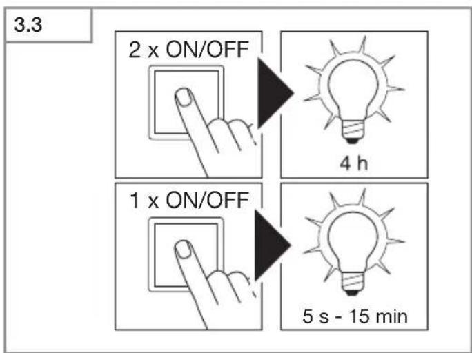
Manual override function
If an optional mains switch is installed in the mains supply lead, the following functions are available in addition to simply switching light ON and OFF:
Manual override (Fig. 3.3)
1) Activate manual override:
Switch OFF and ON twice. The light is set to manual override for 4 hours. Then it returns automatically to sensor mode.
2) Deactivate manual override:
Switch OFF and ON once. Light goes out or switches to sensor operation.
Important:
Switching must take place within 0.2 to 1 second.
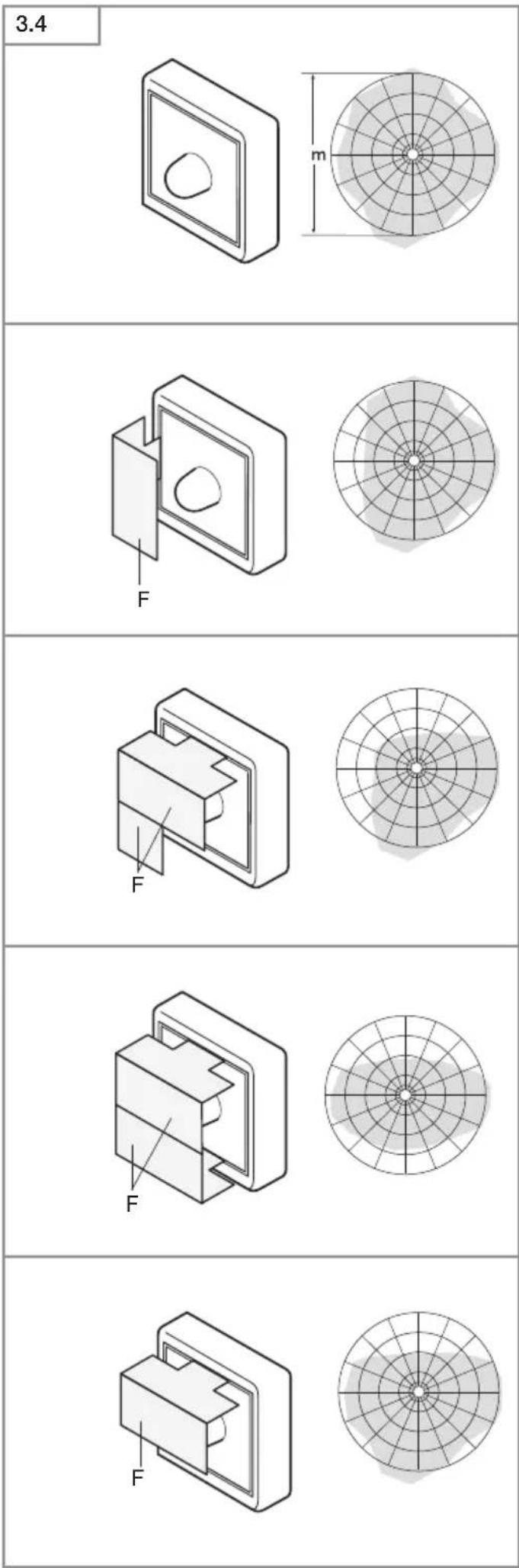
You can reduce reach in four directions by fitting the slot-in shrouds included. (Fig. 3.4)
Operating emergency light module
The emergency light test must always be performed before use.
- Press "test" button, emergency light LEDs ON.
- Release "test" button, emergency light LEDs OFF.
- Optional additional test: disconnect supply from luminaire.
• Emergency light module must switch ON. - The emergency light module can be changed during normal luminaire operation.
- The status LED must always light up after fitting emergency light module, also when performing emergency light test. The optional additional test (disconnecting from the supply) is no substitute for testing using the "test" button.
Emergency light module malfunctions
Green LED charge indicator not lit:
– Emergency light module not properly engaged
- Check mains power connection
- Make sure all rechargeable batteries are fitted and inserted the right way round
Green LED charge indicator ON, emergency light LEDs do not switch ON in response to pressing the "test" button:
– Rechargeable batteries very low
– Rechargeable battery cell faulty or fitted the wrong way round
- Check mains power connection
- Make sure rechargeable batteries are fitted the right way round and check state of charge, changing rechargeable batteries if necessary
Green LED charge indicator OFF. On pressing button, switches ON together with emergency light LEDs
- Make sure all rechargeable batteries are fitted and inserted the right way round
Emergency light LEDs immediately go out on pressing the button
– Rechargeable batteries empty or faulty
- Check emergency light module's mains power connection, green LED charge indicator must be lit
7. Accessories (optional)
- Replacement rechargeable battery emergency light module (3 pcs) EAN 4007841 006457
8. Maintenance and care
The product requires no maintenance.
The luminaire can be cleaned with a damp cloth (without detergents) if dirty.
The emergency light luminaire must be serviced at regular intervals in line with national regulations.
Important note: The control gear cannot be replaced.
9. Disposal
Electrical and electronic equipment, accessories and packaging must be recycled in an environmentally compatible manner.

Do not dispose of electrical and electronic equipment as domestic waste.
EU countries only:
Under the current European Directive on Waste Electrical and Electronic Equipment and its implementation in national law, electrical and electronic equipment no longer suitable for use must be collected separately and recycled in an environmentally compatible manner.

Do not throw devices, rechargeable batteries / batteries into household waste, fire or water at the end of their useful life. Rechargeable batteries /
batteries should be collected, recycled or disposed of in an environmentally friendly manner.
For EU countries only:
In accordance with Directive 2006/66/EC, defective or spent rechargeable batteries / batteries must be recycled. Waste rechargeable / non-rechargeable batteries can be returned to the point of purchase or to a collection facility for hazardous substances.
10. Manufacturer's warranty
Manufacturer's warranty of STEINEL GmbH, Dieselstrasse 80-84, DE-33442 Herzebrock-Clarholz, Germany All STEINEL products meet the highest quality standards. For this reason, we, the manufacturer, are pleased to provide you, the customer, with a warranty under the following terms and conditions:
The warranty covers the absence of deficiencies which are proven to be the result of a material defect or fault in manufacturing and which are reported to us immediately after detection and within the warranty period. The warranty shall cover all STEINEL Professional products sold and used in Germany.
Our warranty cover for consumers
The provisions below apply to consumers.
A consumer is any natural person who, on entering into the purchase transaction, neither acts in exercising their commercial nor their self-employed activity.
You can opt for warranty cover in the form of repair or replacement which will be provided free of charge (if applicable, in the form of a successor model of the same or higher quality) or in the form of a credit note.
In the case of sensors, floodlights, outdoor and indoor lights, the warranty period for the STEINEL Professional product you have purchased is: 5 years
for hot-air and hot-melt gluing products: 1 year in each case from the date on which the product was purchased.
We shall bear the shipping costs but not the transport risks involved in return shipment.
Our warranty cover for entrepreneurs
The provisions below apply to entrepreneurs. Entrepreneur is a natural or legal person or partnership with legal personality who or which, on entering into the purchase transaction, acts in exercising their or its commercial or self-employed activity.
We have the option of providing warranty cover by rectifying deficiencies free of charge, replacing a product free of charge (if applicable, in the form of a successor model of the same or higher quality) or by issuing a credit note. In the case of sensors, floodlights, outdoor and indoor lights, the warranty period for the STEINEL Professional product you have purchased is: 5 years
for hot-air and hot-melt gluing products: 1 year in each case from the date on which the product was purchased.
Within the scope of warranty cover, we shall not bear your expenses accruing from subsequent fulfillment nor shall we bear your expenses for removing the defective product and installing a replacement product.
Statutory rights accruing from defects, gratuitousness
The warranty cover described here shall be applicable in addition to the statutory rights of warranty – including special consumer protection provisions – and shall not restrict or replace them. Exercising your statutory rights in the event of defects is gratuitous.
Exemptions from the warranty
All replaceable lamps are expressly excluded from this warranty.
In addition to this, the warranty shall not cover:
– any wear resulting from use or any other natural wear of product parts or any deficiencies in the STEINEL Professional product that are attributable to wear caused by use or other natural wear,
– any improper or non-intended use of the product or any failure to observe the operating instructions,
– any unauthorised additions, alterations or other modifications to the product or any deficiencies attributable to the use of accessory,
– supplementary or replacement parts which are not genuine STEINEL parts,
– any maintenance or care of products that is not carried out in accordance with the operating instructions,
– any attachment or installation that is not in accordance with STEINEL's installation instructions,
– any damage or loss occurring in transit.
Application of German law
The warranty shall be governed by German law excluding the United Nations Convention concerning the International Sale of Goods (CISG).
Making claims
If you wish to make a warranty claim, please send your product complete and carriage paid with the original receipt of purchase, which must show the date of purchase and product designation, either to your retailer or directly to us at STEINEL (UK) Ltd. – 25 Manasty Road, Axis Park, Orton Southgate, GB- Peterborough Cambs PE2 6UP United Kingdom. For this reason, we recommend that you keep your receipt of purchase in a safe place until the warranty period expires.

11. Declaration of Conformity
Hereby, STEINEL GmbH declares that the radio equipment typeRS PRO LED P1/RS PRO LEDP2/RS PRO LED P3 is in compliance with Directive 2014/53/EU. The full text of the EU declaration of conformity is available at the following internet address: www.steinel.de
- Technical specifications
| Dimensions (∅ x D) P1 S: ∅ 280 × 1 | P1 S / P2 S / P3 S P1 S FLAT / P2 S FLAT | |
| 10 mmP2 S: ∅ 320 × 120 mmP3 S: ∅ 400 × 142 mm | P1 S FLAT: ∅ 272 × 64 mmP2 S FLAT: ∅ 322 × 68 mm | |
| Supply voltage 220–240 V, 50/60 Hz | ||
| Material PMMA (shade) | ||
| Power consumption (Pon) P1 S: NW | 9.40 WP1 S: WW: 9.40 WP2 S (EM) NW: 15.40 WP2 S (EM) WW: 15.10 WP3 S (EM) NW: 18.40 WP3 S (EM) WW: 18.40 W | P1 S FLAT NW: 9.40 WP1 S FLAT WW: 9.40 WP2 S (EM) FLAT NW:15.40 WP2 S (EM) WW:15.10 W |
| Standby sensor (Psb) 0.39 0.39 | ||
| Mains current | P1 S: 230 V–45 mAP2 S: 230 V–75 mAP3 S: 230 V–88 mA | |
| Power factor P1 S: 0.91 | P2 S: 0.91P3 S: 0.93 | |
| Additional switching capacities Filament bulb / halogen load 800 WLED / ECG load: 250 W (50 pcs. c < 88 μF) | ||
GB
| Luminous flux (360°) P1 S NW: 980 | lmP1 S WW: 953 lmP2 S (EM) NW: 1,731 lmP2 S (EM) WW: 1,674 lmP3 S (EM) NW: 2,188 lmP3 S (EM) WW: 2,072 lm | P1 S FLAT NW: 965 lmP1 S FLAT WW: 942 lmP2 S (EM) FLAT NW: 1,700 lmP2 S (EM) FLAT WW: 1,608 lm |
| Efficiency P1 S NW: 104 lm/W | P1 S WW: 101 lm/WP2 S (EM) NW: 112 lm/WP2 S (EM) WW: 110.90 lm/WP3 S (EM) NW: 119 lm/WP3 S (EM) WW: 112.60 lm/W | P1 S FLAT NW: 102.70 lm/WP1 S FLAT WW: 100 lm/WP2 S (EM) FLAT NW: 110 lm/WP2 S (EM) FLAT WW: 106.50 lm/W |
| Luminous flux, emergency light 38 lm | ||
| Colour temperature PMMA 4,000 K | (neutral white = NW)Glass 3,000 K (warm white = WW) | |
| Colour rendering index R | a=82 | |
| Average rated life expectancy L70B | 50 at 25 °C: 60,000 hours | |
| Colour consistency SDCM SDCM 3 | ||
| Luminous intensity distribution | 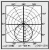 | |
| HF technology 5.8 GHz (responds to the slightest movement regardless of temperature) | ||
| Angle of coverage 360° with 160° angle of aperture | ||
| Transmitter power approx. 1 mW | ||
| Reach ∅ 1-8 m | ||
| Time setting | 5 s-15 min | |
| Basic light level | 10 % | |
| Twilight setting | 2-2,000 lux | |
| IP rating | IP54 | |
| Protection class | II | |
| Temperature range | -10 to +40 °C | |
| Energy efficiency class | P1 S: DP2 S: DP3 S: D | P1 S FLAT NW: EP1 S FLAT WW: EP2 S FLAT NW: DP2 S FLAT WW: D |
13. Technical specifications - rechargeable batteries
3× Panasonic NiMh, HHR 80AAAB, 1.2 V/750 mAH, AAA
Batteries permanently charged at approx. 23 mAh, generating no heat
Charging time: 24 h (permanently connected to mains power)
Rechargeable battery capacity / emergency lighting duration: at least 3 h ^*1)
*1) Maximum capacity only ensured by using rechargeable batteries provided.
Important: Rechargeable batteries must be replaced if the emergency light module stays ON for less than 3 h.
14. Troubleshooting - sensor-switched light
Malfunction Cause Remedy
| Sensor-switched light without power | ■ Fuse has tripped, not switched ON, break in wiring■ Short circuit in mains power supply lead■ Any mains switch OFF | ■ Activate, change fuse, turn ON mains switch, check wiring with voltage tester■ Check connections■ Switch on mains switch |
| Sensor-switched light will not switch ON | ■ Wrong twilight setting selected■ Mains switch OFF■ Fuse has tripped | ■ Reset■ Switch ON■ Activate, change fuse, check connection if necessary |
| Sensor-switched light will not switch OFF | ■ Continued movement within the detection zone | ■ Check detection zone |
| Sensor-switched light switches ON without any identifiable movement | ■ Light not mounted for detecting movement reliably■ Movement occurred, but not identified by the observer (movement behind wall, movement of a small object in immediate lamp vicinity etc.) | ■ Securely mount enclosure■ Check detection zone |
| Sensor-switched light does not switch ON despite movement | ■ To minimise malfunctioning, rapid movements are suppressed or detection zone too small■ Wrong twilight setting selected | ■ Check detection zone■ Reset |
15. Troubleshooting - emergency light module
Malfunction Cause Remedy
| Green charge indicator LED not lit | Emergency light module not properly engagedNo supply voltageEmergency light LEDs faulty | Check mains power connectionReplace rechargeable batteriesMake sure all rechargeable batteries are fitted and inserted the right way round |
| Green charge indicator LED ON, emergency light LEDs do not switch ON in response to pressing the button | Rechargeable batteries very lowRechargeable battery cell is faulty | Check mains power connectionMake sure rechargeable batteries are fitted the right way round and check state of charge |
| Green charge indicator LED OFF. On pressing button, switches ON together with emergency light LEDs | Not all rechargeable batteries fitted or rechargeable batteries inserted the wrong way round | Make sure all rechargeable batteries are fitted and inserted the right way round. If necessary, replace rechargeable batteries |
| Emergency light LEDs immediately go out on pressing the "test" button | Rechargeable batteries empty or faulty | Check emergency light module's mains power connection, green charge indicator LED must be lit |
FR
9. Recyclage
- Accu's leeg of defect
9. Verwijderen
9. Reciclagem
G Grunnlysinnstilling
H Tidsinnstilling
I Rekkeviddeinnstilling
J Skumringsinnstilling
K Nødlysmodul (ekstrautstyr)
L Status-LED
M Knapp «Test»
Permanent lys (ill. 3.3)
1) Tenne permanent lys:
9. Likvidace
9. Utylizacja
9. 废弃物处理
natural_image
World map silhouette in grayscale, showing continents and oceans without any text or labelsContact
www.steinel.de/contact


- DE
- Please read carefully and keep in a safe place.
- Symbols
- General safety precautions
- RS PRO LED P1 S / FLAT RS PRO LED P2 S / FLAT RS PRO LED P3 S / FLAT
- Proper use
- Note:
- Detection zones for ceiling mounting:
- Detection zones for wall mounting:
- Package contents for emergency light P3 (Fig. 1.3)
- Product dimensions for P1 / P2 / P3 (Fig. 1.4)
- Product dimensions for P1 FLAT / P2 FLAT (Fig. 1.5)
- Product components
- Luminous intensity distribution (Fig. 1.10)
- Electrical connection
- Wiring diagram (Fig. 1.1)
- Important:
- Mounting
- Installation procedure
- Function
- Factory settings
- Control dials (Fig. 3.2)
- Twilight setting (response threshold) (J)
- Reach setting (sensitivity) (I)
- Time setting (stay-ON time) (H)
- Basic light level function (G)
- Manual override function
- Manual override (Fig. 3.3)
- 1) Activate manual override:
- 2) Deactivate manual override:
- Operating emergency light module
- Emergency light module malfunctions
- Accessories (optional)
- Maintenance and care
- Disposal
- EU countries only:
- For EU countries only:
- Manufacturer's warranty
- Our warranty cover for consumers
- Our warranty cover for entrepreneurs
- Statutory rights accruing from defects, gratuitousness
- Exemptions from the warranty
- Application of German law
- Making claims
- Declaration of Conformity
- Technical specifications - rechargeable batteries
- Troubleshooting - sensor-switched light
- Troubleshooting - emergency light module
- FR
- Recyclage
- Verwijderen
- Reciclagem
- Permanent lys (ill. 3.3)
- 1) Tenne permanent lys:
- Likvidace
- Utylizacja
- 废弃物处理
- Contact
Brand : STEINEL
Model : RS PRO P3 S
Category : Lamp