IS 2360 - Motion detector STEINEL - Free user manual and instructions
Find the device manual for free IS 2360 STEINEL in PDF.
Download the instructions for your Motion detector in PDF format for free! Find your manual IS 2360 - STEINEL and take your electronic device back in hand. On this page are published all the documents necessary for the use of your device. IS 2360 by STEINEL.
USER MANUAL IS 2360 STEINEL
Ø 6 mm only IP 54 if installed
2 W < LED < 8 W: 300 W
Installation instructions About these instructions Instructions to take action are shown as follows: ► Instruction to take action In the safety advice, the warning symbol and signal word indicate the severity of
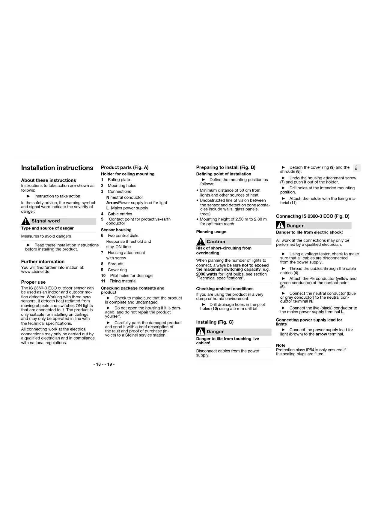
Signal word Type and source of danger Measures to avoid dangers ► Read these installation instructions before installing the product. Further information You will find further information at: www.steinel.de Proper use The IS 2360-3 ECO outdoor sensor can be used as an indoor and outdoor mo- tion detector. Working with three pyro sensors, it detects heat radiated from moving objects and switches ON lights that are connected to it. The product is only suitable for installing on ceilings and may only be operated in line with the technical specifications. All connecting work at the electrical connections may only be carried out by a qualified electrician and in compliance with national regulations. Product parts (Fig. A) Holder for ceiling mounting 1 Rating plate 2 Mounting holes 3 Connections N neutral conductor Arrow Power supply lead for light L Mains power supply 4 Cable entries 5 Contact point for protective-earth conductor Sensor housing 6 two control dials: Response threshold and stay-ON time 7 Housing attachment with screw 8 Shrouds 9 Cover ring 10 Pilot holes for drainage 11 Fixing material Checking package contents and product ► Check to make sure that the product is complete and undamaged. ► Do not open the housing if it is dam- aged, and do not repair the product yourself. ► Carefully pack the damaged product and send it with a brief description of the fault and proof of purchase (in- voice) to a Steinel service station. Preparing to install (Fig. B) Defining point of installation ► Define the mounting position as follows:
- Minimum distance of 50cm from lights and other sources of heat
- Unobstructed line of vision between the sensor and detection zone (obsta- cles include walls, glass panels, trees)
- Mounting height of 2.50m to 2.80m for optimum reach Planning usage
Caution Risk of short-circuiting from overloading When planning the number of lights to connect, always be sure not to exceed the maximum switching capacity, e.g. 2000watts for light bulbs, see section "Technical specifications". Checking ambient conditions If you are using the product in a very damp or humid environment: ► Drill drainage holes in the pilot holes(10) using a 5 mm drill bit Installing (Fig. C)
Danger Danger to life from touching live cables! Disconnect cables from the power supply! ► Detach the cover ring (9) and the shrouds (8). ► Undo the housing attachment screw (7) and push it out of the holder. ► Drill holes at the intended mounting position. ► Attach the holder with the fixing ma- terial (11). Connecting IS 2360-3 ECO (Fig. D)
Danger Danger to life from electric shock! All work at the connections may only be performed by a qualified electrician. ► Using a voltage tester, check to make sure that all cables are disconnected from the power supply. ► Thread the cables through the cable entries (4). ► Attach the PE conductor (yellow and green conductor) at the contact point (5). ► Connect the neutral conductor (blue or grey conductor) to the neutral con- ductor terminal N. ► Connect the live (black) conductor to the mains power supply terminal L. Connecting power supply lead for lights ► Connect the power supply lead for light (brown) to the arrow terminal. Note Protection class IP54 is only ensured if the sealing plugs are fitted.- 20 - - 21 -
Danger Danger to life from electric shock! All work at the connections may only be performed by a qualified electrician. Connecting lights ► Connect lights that do not have a neutral conductor as shown in con- nection example 1. ► Connect lights that do have a neutral conductor as shown in connection example 2. Installing two-circuit switch If you want to switch OFF all connected lights via switch: ► install a two-circuit switch for manual and automatic operation (connection example 3). Installing two-way switch If you want to switch ON and OFF manually and also use sensor mode (automatic): ► Install a two-way switch (connection example 4). Two-way switch options:
- Position I Sensor mode (switching ON and OFF automatically)
- Position II manual operating mode: switching ON and OFF via switch; after switching OFF, sensor mode is reactivated Activating and deactivating manual override A two-way switch provides a manual override function for lights connected. To activate manual override: ► Turn the light switch to the OFF and ON positions twice in rapid succes- sion (within less than half a second). Manual override keeps light ON per- manently for four hours and then re- turns to sensor mode. To deactivate manual override: ► Turn the light switch to the OFF and ON position once in rapid succession (within less than half a second). The light immediately switches to sensor mode. Settings (Fig. F) During installation or at a later time, you can infinitely adjust the stay-ON time and the response threshold via the con- trol dials. ► Using a screwdriver, turn the control dials to the chosen positions: Stay-ON time + maximum: 15minutes – minimum: 5seconds If you have set a stay-ON time of 15minutes, the sensor will switch OFF the connected lights after 15minutes. If the sensor detects further move- ment, the stay-ON time will start from the beginning again. Using the response threshold, you can infinitely adjust the level of ambient light at which the sensor switches on the lights connected. Response threshold + maximum: 1000 lux Daylight mode: the sensor switches light ON in day- light when it identifies a movement. – minimum: 2 lux Twilight setting: the sensor switches light ON at twi- light. If the ambient bright- ness is brighter than 2lux, the sensor does not switch light ON. Detection zone (Fig. G) Is the sensor switching light ON too often because it is being triggered by objects in the detection zone (e.g. in response to passing vehicles)? You can mask the sensor with shrouds (8) to restrict the detection zone. ► Detach the cover ring and the shrouds. ► Using a pair of scissors, cut the shrouds to size horizontally and/or vertically. ► Fit the shrouds to the sensor and, if necessary, adjust them to the appro- priate position. ► Re-fit the cover ring. Operation Perform function test ► Set the response threshold to the cur- rent ambient brightness. The factory setting is daylight operation. ► Set the stay-ON time to a very short period. The factory setting is 5seconds. ► Fit the sensor housing onto the holder and push it home until it clips into place. ► Tighten the housing attachment screw (7). ► Switch the power ON. ► Check whether the sensor responds to a movement and switches the light ON. If it does, the sensor is ready for opera- tion: ► Select your chosen settings and refit the cover ring (9). If it does not: ► Check the connections and the volt- age supply. Troubleshooting
Danger Danger to life from touching live components! All work at the connections may only be performed by a qualified electrician. Dis- connect cables from the power supply!- 22 - - 23 -
AttentionProduct damage from improper servicingServicing or repair work may only be performed by Steinel service stations.Sensor will not switch ONEither incorrect settings have been made, there is a power-related fault or the sensor is faulty: ► Check the setting for the response threshold and, if necessary, set a higher lux level. ► Check the cables, connections and the voltage supply, change a fuse if necessary. ► Carry out a function test on the sen-sor and on the lights connected, re-placing any faulty items.Sensor will not switch OFFEither incorrect settings have been made, manual override is activated or there is permanent movement or a source of heat in the detection zone. ► Check whether the response thresh-old setting is too low, correcting the setting if necessary. ► Check whether the light has been switched ON manually via a switch. ► Check whether there are any sources of heat or anything else inadvertently triggering the sensor in the detection zone and remove them. ► If necessary, limit the detection zone with the shrouds. ► Increase distance between Wi-Fi device and sensor >3mSensor switching ON when it should notThe sensor is detecting constant move-ment or a source of heat in the detection zone, causing it to switch ON too often or when it should not. ► Check the detection zone for sources of heat or movement. ► Eliminate permanent sources of heat from the detection zone. ► If necessary, limit the detection zone with the shrouds. ► Increase distance between Wi-Fi device and sensor >3m Disposal Electrical and electronic equipment, ac-cessories and packaging must be recy-cled in an environmentally compatible manner.Do not dispose of electrical and electronic equipment as domes-tic waste.EU countries only:Under the current European Directive on Waste Electrical and Electronic Equip-ment and its implementation in national law, electrical and electronic equipment no longer suitable for use must be col-lected separately and recycled in an en-vironmentally compatible manner. Manufacturer’s Warranty MANUFACTURER'S
WARRANTYMANUFACTURER'S YEAR WARRANTY MANUFACTURER'S YEAR WARRANTY As purchaser, you are entitled to your statutory rights against the vendor. If these rights exist in your country, they are neither curtailed nor restricted by our Warranty Declaration. We guarantee that your STEINEL Professional sensor prod-uct will remain in perfect condition and proper working order for a period of 5years. We guarantee that this product is free from material-, manufacturing- and design flaws. In addition, we guar-antee that all electronic components and cables function in the proper man-ner and that all materials used and their surfaces are without defects.Making ClaimsIf you wish to make a claim, please send your product complete and carriage paid with the original receipt of pur-chase, which must show the date of purchase and product designation, either to your retailer or contact us at STEINEL (UK) Limited, 25Manasty Road, Axis Park, Orton Southgate, Peterborough, PE2 6UP, for a returns number. For this reason, we recommend that you keep your receipt of purchase in a safe place until the warranty period expires. STEINEL shall assume no liabili-ty for the costs or risks involved in returning a product. For information on making claims under the terms of the warranty, please go to www.steinel-professional.de/garantieIf you have a warranty claim or would like to ask any question regarding your product, you are welcome to call us at any time on our Service Hotline 01733 366700. Technical specifications Dimensions and versionsDiameter × height121mm x 57mmColours whiteSpecificationsSupply voltage 220 – 240VMains frequency 50 / 60HzSwitching capacityIncandescent / halogen lamp load: 2000 WFluorescent-lamp electronic ballasts: 1500 WFluorescent lamps, uncorrected: 500 VAFluorescent lamps, series-corrected: 900 VAFluorescent lamps, parallel-corrected: 400 VALow-voltage halogen lamps: 2000 VALED < 2 W: 100 W2 W < LED < 8 W: 300 WLED > 8 W: 600 WCapacitive load: 176 µF- 24 - - 25 -
Sensor Sensor technology Passive infrared, 3 pyro sensors Angle of coverage 360° Angle of aperture 90° Sneak-by guard provided Reach and settings Detection zone and reach 12m, at a mounting height of 2.50m to 2.80m Switching ON at threshold levels 2lux to 1000 lux, (daylight operation) Stay-ON time, continuously variable 5seconds to 15minutes Environment IP rating IP54 Temperature range –20°C to +50°C