
DL Vario Quattro LED - Motion detector STEINEL - Free user manual and instructions
Find the device manual for free DL Vario Quattro LED STEINEL in PDF.
| Product type | LED motion detector for ceiling, indoor and outdoor |
| Brand | Steinel |
| Model | DL Vario Quattro LED |
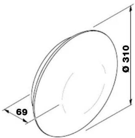
| Dimensions (diameter × depth) | ∅ 310 × 69 mm |
| Weight | Approx. 0.8 kg (estimate) |
| Power supply | 220-240 V ~ 50/60 Hz |
| Power consumption (on) | 9.80 W |
| Standby power | 0.42 W |
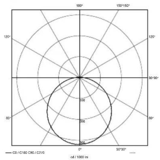
| Luminous flux | 1000 lm (360°) |
| Color temperature | 3000 K (warm white) |
| Color rendering index (CRI) | 82 |
| Average LED lifespan | > 60,000 h (L70B50 at 25 °C) |
| Detection technology | PIR, 4 pyrodetectors |
| Detection area | 360° |
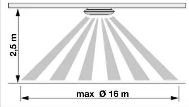
| Detector range | Up to 16 × 16 m (mounting height 2.5 m), adjustable from 4 × 4 m |
| Time delay | From 5 seconds to 30 minutes |
| Trigger threshold adjustment | From 2 to 1000 lux (twilight/day) |
| Orientation light function | Off, 10 min, 30 min, all night |
| Ingress protection | IP54 |
| Protection class | II |
| Impact resistance | IK07 |
| Ambient temperature | -20 to +35 °C |
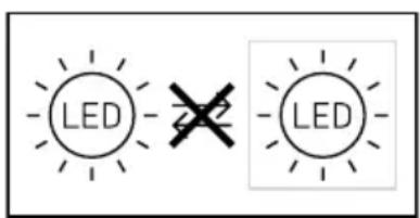
| Replaceability of light source | Not replaceable (complete luminaire must be replaced) |
| Manufacturer warranty | 36 months |
Frequently Asked Questions - DL Vario Quattro LED STEINEL
User questions about DL Vario Quattro LED STEINEL
0 question about this device. Answer the ones you know or ask your own.
Ask a new question about this device
Download the instructions for your Motion detector in PDF format for free! Find your manual DL Vario Quattro LED - STEINEL and take your electronic device back in hand. On this page are published all the documents necessary for the use of your device. DL Vario Quattro LED by STEINEL.
USER MANUAL DL Vario Quattro LED STEINEL
natural_image
Top-down view of a smooth, oval-shaped object with a gradient shading (no text or symbols)
GB .....12 Follow written instructions!
natural_image
Technical line drawing of a mechanical component with multiple parts including a circular base, screw holes, and a rod (no text or symbols)3.2
3.3
3.4
3.5
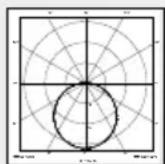
radar
| Angle | Value | |-------|-------| | 0° | 300 | | 30° | 250 | | 60° | 200 | | 90° | 150 | | 120° | 100 | | 150° | 50 | | 180° | 0 |4.1
5.1
natural_image
Technical diagram of a mechanical component with no visible text or symbols5.2
5.3
natural_image
Technical line drawing of a mechanical device with internal components and directional arrows (no text or symbols)5.4
6.1
natural_image
Mechanical diagram showing a lever mechanism with rotating components and directional arrows (no text or symbols)6.2
Please read carefully and keep in a safe place.
– Under copyright. Reproduction either in whole or in part only with our consent.
– Subject to change in the interest of technical progress.
Symbols

Hazard warning!

Reference to other information in the document.
2. General safety precautions

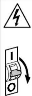
Disconnect the power supply before attempting any work on the unit.
- During installation, the electric power cable being connected must not be live. Therefore, switch off the power first and use a voltage tester to make sure the wiring is off-circuit.
- Installing the sensor-switched light involves work on the mains supply voltage. This work must therefore be carried out professionally in accordance with national wiring regulations and electrical operating conditions. (e.g.: DE: VDE 0100, AT: ÖVE / ÖNORM E8001-1, CH: SEV 1000)
- Only use genuine replacement parts.
- Repairs may only be made by specialist workshops.
3. DL Vario Quattro S
Proper use
- The Vario Quattro is a sensor-switched light for indoor and outdoor ceiling mounting.
The sensor-switched light is equipped with four pyro sensors that detect the invisible heat emitted by moving objects (people, animals, etc.). The heat detected in this way is converted electronically into a signal that switches the light ON. Heat is not detected through obstacles, such as walls or panes of glass, and will therefore not activate the light.
Note:
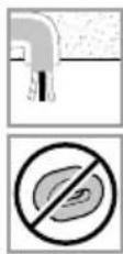
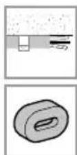
The light's shade is susceptible to scratching. The light must not be installed near radiant heaters.
Package contents (Fig. 3.1)
- Sensor-switched light
- 3 spacers
- 3 wall plugs
- 3 screws
- Retaining strap
Product dimensions (Fig. 3.2)
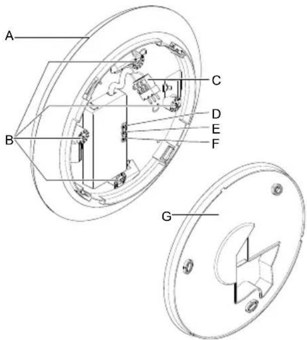
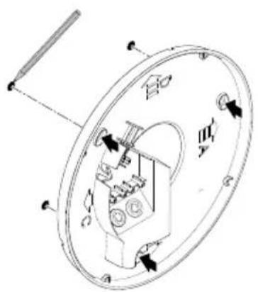
Product components (Fig. 3.3)
A Light
B Reach adjustment
D Twilight setting
E Time setting
F Basic light level
G Ceiling mount
C Connecting terminal
Detection zone (Fig. 3.4)
Luminous intensity distribution (Fig. 3.5)
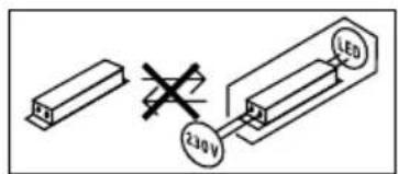
4. Electrical connection
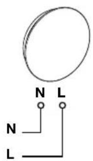
Wiring diagram (Fig. 4.1)
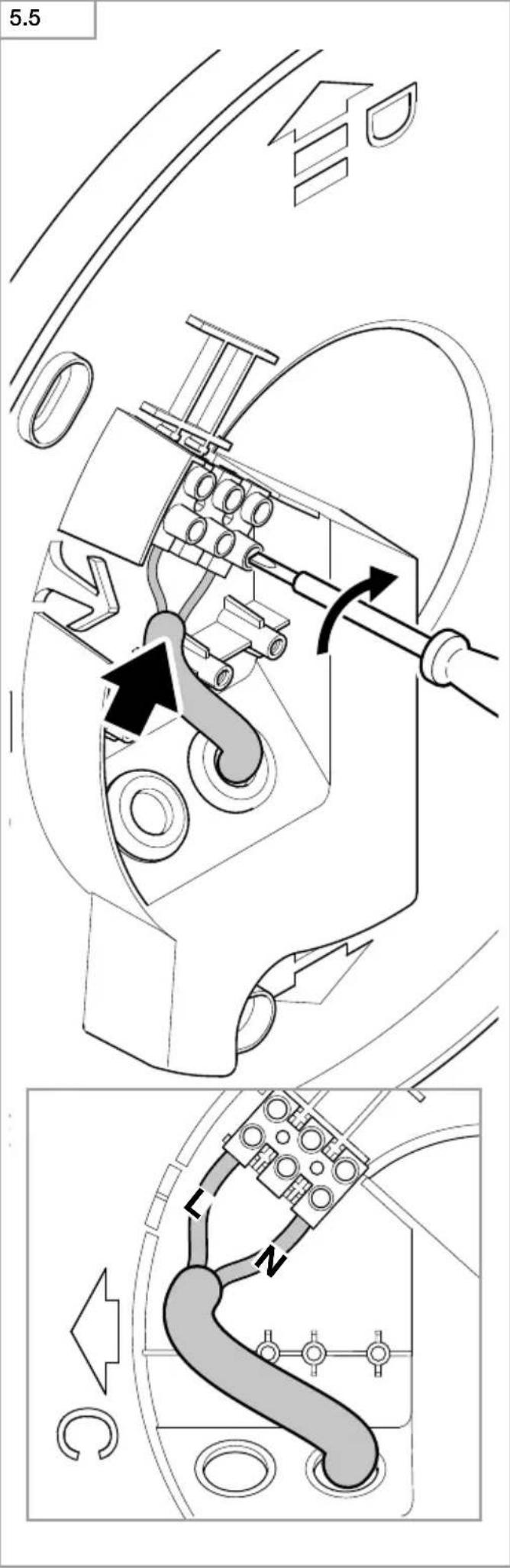
The mains supply lead is a 3-core cable (max. lead diameter 19 mm):
L = phase conductor ( usually black, brown or grey )
N = neutral conductor ( usually blue )
PE = protective-earth conductor (green/yellow)
If you are in any doubt, identify the conductors using a voltage tester; then disconnect from the power supply again. Connect the phase conductor (L) and neutral conductor (N) to the terminal block. Insulate protective-earth conductor (PE) and place it next to terminal block.
Important:
Mixing up the connections will produce a short circuit in the product or your fuse box. In this case, you must identify the individual conductors once again and reconnect them. A mains power switch for turning the unit ON and OFF may of course be installed in the mains supply lead.
The light source of this luminaire cannot be replaced. If the light source needs to be replaced (e.g. at the end of its service life), the complete luminaire must be replaced.
5. Mounting
- Check all components for damage.
- Do not use the product if it is damaged.
- Select an appropriate mounting location, taking the reach and motion detection into consideration.
- When installing the sensor-switched light on the ceiling, make sure the installation site is not exposed to vibration.
Mounting procedure
- Switch OFF power supply (Fig. 4.1)
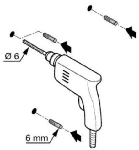
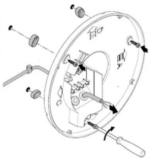
• Mark drill holes (Fig. 5.1) - Drill holes and insert wall plugs (Fig. 5.2)
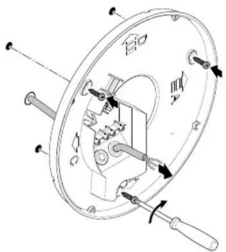
- Installation with concealed power supply lead (Fig. 5.3)
- Installation with surface-mounted power supply lead (Fig. 5.4)
- Connect conductors (Fig. 5.5)
- Make settings → "6. Function"
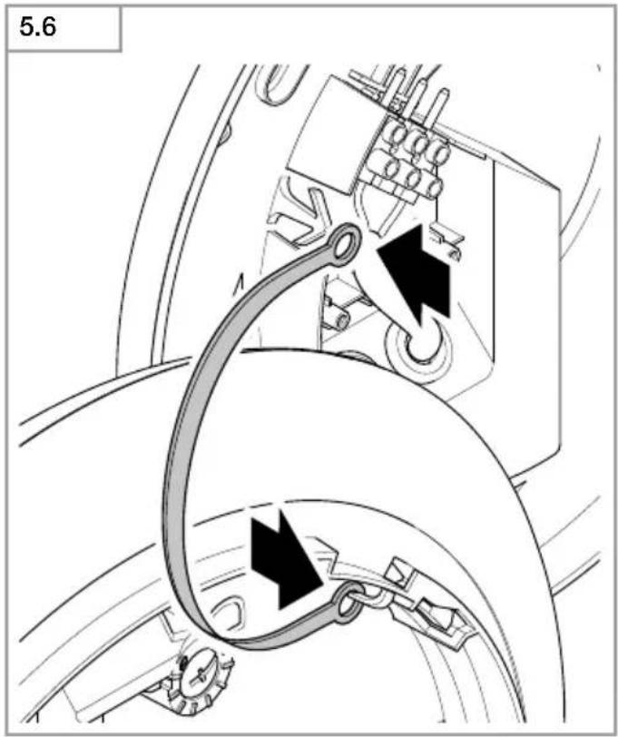
- Attach retaining strap (Fig. 5.6)
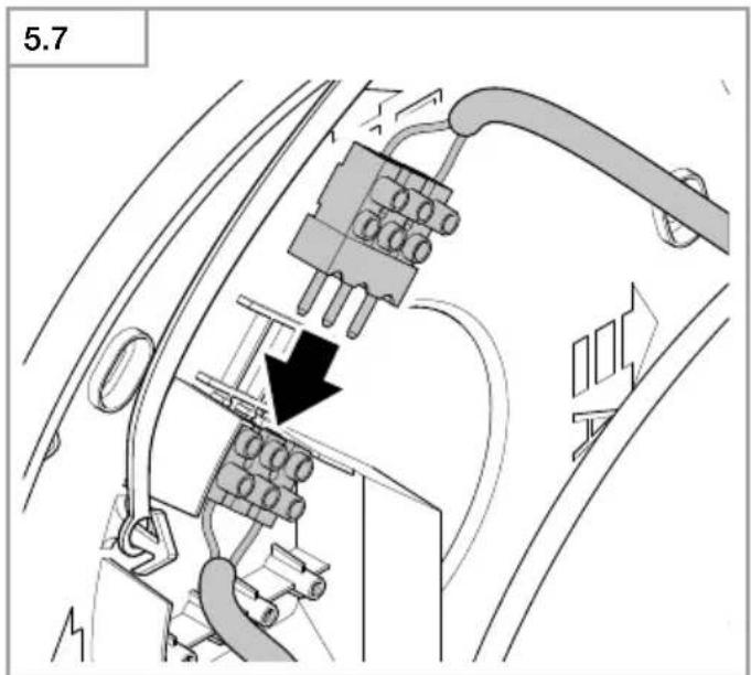
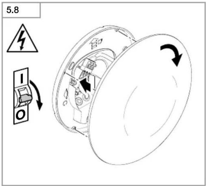
• Make plug connection (Fig. 5.7)
• Fit light shade (Fig. 5.8) - Switch ON power supply (Fig. 5.8)
6. Function
Factory settings:
Twilight level: 1000 lux
Time setting: 5 seconds
Basic light level: OFF
The sensor-switched light can be put into service after mounting the enclosure and connecting to the mains power supply. When putting into operation manually at the mains switch, the light will switch OFF after approx. 30 seconds for the calibration phase and is then activated for sensor mode. It is not necessary to operate the mains switch a second time.
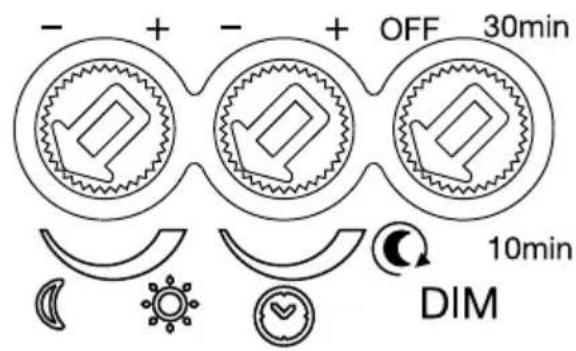
Functions - control dials (Fig. 6.1)
Twilight setting (response threshold) (Fig. 6.2/D)
The chosen response threshold can be infinitely varied from approx. 2 to 1000 lux.
- Control dial set to = daylight mode (depending on ambient brightness)
- Control dial set to = twilight mode (approx. 2 lux)
The control dial must be turned to 📋 when adjusting the detection zone and performing the functional test in daylight.
Time setting (stay-ON time) (Fig. 6.2/E)
The light's ON time can be set to any period from approx. 5 seconds to a maximum of 30 minutes. Any movement detected before this time elapses restarts the stay-ON time (for switch-off delay).
Note:
After the light switches OFF, it takes approx. 1 second before it is able to start detecting movement again. The light will only switch ON in response to movement once this period has elapsed.
The shortest time setting is recommended when adjusting the detection zone and performing the functional test.
Basic light level (Fig. 6.2/F)
The basic light level function provides illumination at approx. 10% light output when the brightness setting is reached.
Any one of four settings can be selected for the basic light level required:
- OFF
- 10 minutes after selected time elapses
- 30 minutes after selected time elapses
- all night
Basic light switches OFF every hour to measure ambient brightness. Basic light switches back ON again after a short period.
Manual override function
If an optional mains switch is installed in the mains supply lead, the following functions are available in addition to simply switching light ON and OFF:
Manual override (Fig. 6.3)
1) Activate manual override:
Switch OFF and ON twice. The light is set to manual override for 4 hours. Then it returns automatically to sensor mode.
2) Deactivate manual override:
Switch OFF and ON once. Light switches OFF or switches to sensor operation.
Important:
Switching must take place within 0.2 to 1 second.
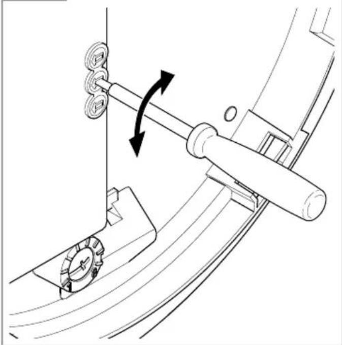
Reach adjustment
Reach can be infinitely adjusted in four directions via four control dials from 2 m to 8 m independently of each other. The detection reach is selected via the control dials (Fig. 6.4).
Detection diagram (Fig. 6.5)
The shaded zones show the areas that can be masked out by customising the reach setting.
(Fig. 6.6)
Detection reach table
| Adjustment | Mounting height 2.5 m | |
| radial tangential | ||
| 1 2.4 m | × 2.4 m | 4 m × 4 m |
| 2 3.2 m | × 3.2 m | 6 m × 6 m |
| 3 3.6 m | × 3.6 m | 7.3 m × 7.3 m |
| 4 4 m × | 4 m | 8.6 m × 8.6 m |
| 5 4.4 m | × 4.4 m | 10.2 m × 10.2 m |
| 6 5 m × | 5 m | 12.6 m × 12.6 m |
| 7 6 m × | 6 m | 15.7 m × 15.7 m |
| 8 6 m × | 6 m | 16 m × 16 m |
| Adjustment | Mounting height 2.8 m | |
| radial tangential | ||
| 1 3 m × 3 m | 5.4 m × 5.4 m | |
| 2 3.4 m × 3.4 m | 6.4 m × 6.4 m | |
| 3 3.8 m × 3.8 m | 7.5 m × 7.5 m | |
| 4 4.4 m × 4.4 m | 8.8 m × 8.8 m | |
| 5 5.4 m × 5.4 m | 10.4 m × 10.4 m | |
| 6 5.6 m × 5.6 m | 13.1 m × 13.1 m | |
| 7 6 m × 6 m | 17 m × 17 m | |
| 8 6 m × 6 m | 17.3 m × 17.3 m | |
| Adjustment | Mounting height 3.0 m | |
| radial tangential | ||
| 1 3.4 m | × 3.4 m 6.2 m × 6.2 m | |
| 2 3.6 m | × 3.6 m 6.6 m × 6.6 m | |
| 3 4 m × | 4 m 7.7 m × 7.7 m | |
| 4 4.8 m | × 4.8 m 9 m × 9 m | |
| 5 6 m × | 6 m 10.6 m × 10.6 m | |
| 6 6 m × | 6 m 13.4 m × 13.4 m | |
| 7 6 m × | 6 m 17.9 m × 17.9 m | |
| 8 6 m × | 6 m 18.1 m × 18.1 m | |
| Adjustment | Mounting height 6.0 m | |
| radial tangential | ||
| 1 5.7 m | × 5.7 m 11 m × 11 m | |
| 2 6 m × | 6 m 11.7 m × 11.7 m | |
| 3 6.7 m | × 6.7 m 13.6 m × 13.6 m | |
| 4 8 m × | 8 m 16 m × 16 m | |
| 5 | 10 m × 10 m | 18.7 m × 18.7 m |
| 6 | 10 m × 10 m | 23.8 m × 23.8 m |
| 7 | 10 m × 10 m | 31.7 m × 31.7 m |
| 8 | 10 m × 10 m | 32 m × 32 m |
7. Maintenance
The light can be cleaned with a damp cloth (without detergents) if dirty.
Important note: the control gear cannot be replaced.
8. Disposal
Electrical and electronic equipment, accessories and packaging must be recycled in an environmentally compatible manner.

Do not dispose of electrical and electronic equipment as domestic waste.
EU countries only:
Under the current European Directive on Waste Electrical and Electronic Equipment and its implementation in national law, electrical and electronic equipment no longer suitable for use must be collected separately and recycled in an environmentally compatible manner.
9. Manufacturer's warranty
This Steinel product has been manufactured with utmost care, tested for proper operation and safety and then subjected to random sample inspection. Steinel guarantees that it is in perfect condition and proper working order. The warranty period is 36 months and starts on the date of sale to the consumer. We will remedy defects caused by material flaws or manufacturing faults. The warranty will be met by repair or replacement of defective parts at our own discretion. The warranty shall not cover damage to wear parts, damage or defects caused by improper treatment or maintenance. Further consequential damage to other objects shall be excluded.
Claims under the warranty will only be accepted if the unit is sent fully assembled and well-packed with a brief description of the fault, a receipt or invoice (date of purchase and dealer's stamp) to the appropriate Service Centre.
Repair service:
If defects occur outside the warranty period or are not covered by the warranty, ask your nearest service station for the possibility of repair.

- Technical specifications
| Dimensions (Ø × T) ∅ 310 × 69 mm |
| Supply voltage 220-240 V 50/60 Hz |
| Power consumption (Pon) 9.80 W |
| Luminous flux (360°) 1,000 lm |
| Efficiency 102 lm/W |
| Standby sensor (Psb) 0.42 W |
| Colour temperature 3,000 K (warm white) |
| Colour rendering index R a = 82 |
| Average rated life expectancy L70B50 at 25°C: >60,000 hours |
| Colour consistency SDCM Starting value: 3 |
| Sensor technology | PIR, 4 pyros |
| Detection zone | 360° |
| Detection reach | 16 x 16 m detection areas for a mounting height of 2.50 m, can be reduced to an area of 4 x 4 m |
| Time setting | 5 s - 30 min |
| Twilight setting | 2-1,000 lux |
| Basic light level function | OFF, 10 min, 30 min, all night |
| IP rating | IP54 |
| Protection class | II |
| Impact resistance | IK 07 |
| Ambient temperature | -20 to +35°C |

Technical documentation at www.steinel.de
Energy efficiency class This product contains an energy efficiency class "D" light source.
11. Troubleshooting
Malfunction Cause Remedy
| Sensor-switched light without power | ■ Fuse has tripped, not switched ON, break in wiring■ Short circuit in mains power supply lead■ Any mains switch OFF | ■ Activate, change fuse, turn ON power switch, check wiring with voltage tester■ Check connections■ Switch on mains switch |
| Sensor-switched light will not switch ON | ■ Incorrect twilight setting selected■ Mains switch OFF■ Fuse has tripped | ■ Readjust■ Switch ON■ Activate, change fuse, check connection if necessary |
| Sensor-switched light will not switch OFF | ■ Continued movement within the detection zone | ■ Check detection zone |
| Sensor-switched light switches ON without any identifiable movement | ■ Light not mounted for detecting movement reliably■ Movement occurred, but not identified by the observer ( movement behind wall, movement of a small object in immediate lamp vicinity etc.) | ■ Securely mount enclosure■ Check detection zone |
| Sensor-switched light does not switch ON despite movement | ■ Rapid movements are suppressed to minimise malfunctioning or detection zone set too small■ Incorrect twilight setting selected | ■ Check detection zone■ Readjust |
FR
Dimensioni (∅ × P) ∅ 310 × 69 mm
8. Eliminación
8. Hävittäminen
Permanent lys (ill. 6.3)
1) Tenne permanent lys:
5. Szerelés
5. Montáž
5. Montaaž
8. Utiliseerimine
5. Montāža
8. Utilizācija
8. Утилизация
5. 安装
natural_image
World map silhouette in grayscale, showing continents and oceans without any text or labelsContact
www.steinel.de/contact


- Please read carefully and keep in a safe place.
- Symbols
- General safety precautions
- DL Vario Quattro S
- Proper use
- Note:
- Package contents (Fig. 3.1)
- Product components (Fig. 3.3)
- Electrical connection
- Wiring diagram (Fig. 4.1)
- Important:
- Mounting
- Mounting procedure
- Function
- Factory settings:
- Functions - control dials (Fig. 6.1)
- Twilight setting (response threshold) (Fig. 6.2/D)
- Time setting (stay-ON time) (Fig. 6.2/E)
- Basic light level (Fig. 6.2/F)
- Manual override function
- Manual override (Fig. 6.3)
- 1) Activate manual override:
- 2) Deactivate manual override:
- Reach adjustment
- Detection diagram (Fig. 6.5)
- Maintenance
- Disposal
- EU countries only:
- Manufacturer's warranty
- Repair service:
- Troubleshooting
- FR
- Eliminación
- Hävittäminen
- Permanent lys (ill. 6.3)
- 1) Tenne permanent lys:
- Szerelés
- Montáž
- Montaaž
- Utiliseerimine
- Montāža
- Utilizācija
- Утилизация
- 安装
- Contact
Brand : STEINEL
Model : DL Vario Quattro LED
Category : Motion detector