
IR 180 COM1 - Motion detector STEINEL - Free user manual and instructions
Find the device manual for free IR 180 COM1 STEINEL in PDF.
| Product type | Passive infrared motion detector |
| Brand | Steinel |
| Model | IR 180 COM1 |
| Dimensions (W × H × D) | 80 × 80 × 50 mm |
| Power supply | 220-240 V ~, 50/60 Hz |
| Detection technology | Pyroelectric infrared sensor |
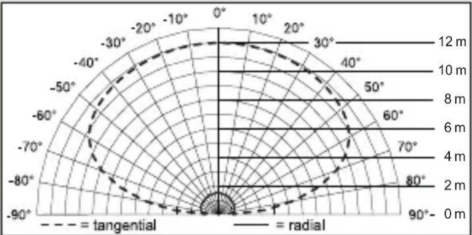
| Detection angle | 180° |
| Maximum range | Approx. 12 m (tangential), 3 m (radial) |
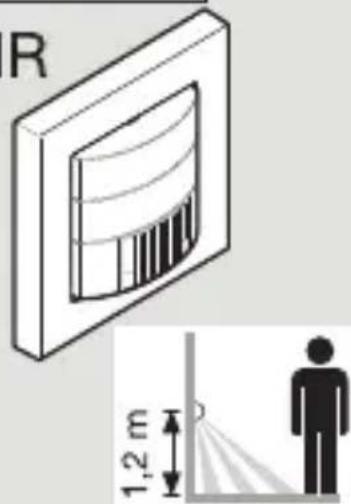
| Recommended installation height | 1.1 m |
| Brightness threshold setting | 2 to 1000 lx, day/night operation |
| Time delay setting | 30 s to 30 min, pulse mode (2 s), IQ mode (self-learning 5-20 min) |
| Switching output 1 (lighting) | Up to 2000 W (incandescent/halogen), 1000 W (electronic fluorescent), 300 W (LED 2-8 W) |
| Switching output 2 (presence, COM2) | Max. 230 W/230 V, 1 A, for HVAC |
| Protection rating | IP20 |
| Operating temperature | 0 °C to +40 °C |
| Remote control options | RC 5, RC 8, Smart Remote (Bluetooth) |
| Installation | Indoor wall mounting, electrical connection by a professional |
| Maintenance and cleaning | Clean with a soft, dry cloth, avoid abrasive products |
| Spare parts and repairability | Use only original parts, repairs by specialized workshops |
| Manufacturer warranty | 5 years |
| Standards | Compliant with Directive 2014/53/EU, NF C-15100 for installation |
Frequently Asked Questions - IR 180 COM1 STEINEL
User questions about IR 180 COM1 STEINEL
0 question about this device. Answer the ones you know or ask your own.
Ask a new question about this device
Download the instructions for your Motion detector in PDF format for free! Find your manual IR 180 COM1 - STEINEL and take your electronic device back in hand. On this page are published all the documents necessary for the use of your device. IR 180 COM1 by STEINEL.
USER MANUAL IR 180 COM1 STEINEL
Follow written instructions!
FR. 34
4.5
Master/Master COM1/COM2


cable length < / = 50 m
4.6
Master/Slave


cable length < / = 50 m


5.1
IR
HF
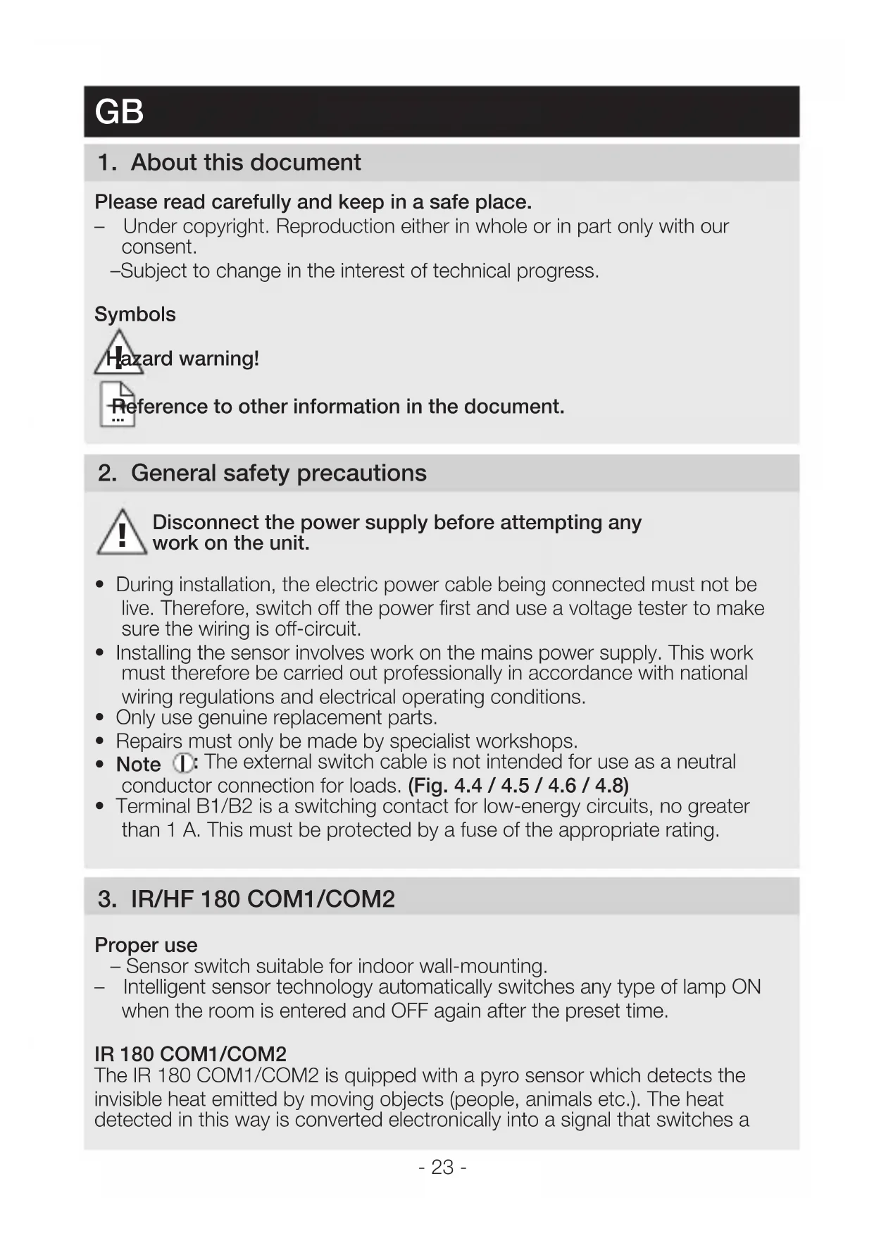
Please read carefully and keep in a safe place.
- Under copyright. Reproduction either in whole or in part only with our consent.
-Subject to change in the interest of technical progress.
Symbols

Hazard warning!
Reference to other information in the document.
2. General safety precautions

Disconnect the power supply before attempting any work on the unit.
- During installation, the electric power cable being connected must not be live. Therefore, switch off the power first and use a voltage tester to make sure the wiring is off-circuit.
- Installing the sensor involves work on the mains power supply. This work must therefore be carried out professionally in accordance with national wiring regulations and electrical operating conditions.
- Only use genuine replacement parts.
- Repairs must only be made by specialist workshops.
- Note ①: The external switch cable is not intended for use as a neutral conductor connection for loads. (Fig. 4.4 / 4.5 / 4.6 / 4.8)
- Terminal B1/B2 is a switching contact for low-energy circuits, no greater than 1 A. This must be protected by a fuse of the appropriate rating.
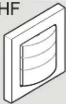
3. IR/HF 180 COM1/COM2
Proper use
- Sensor switch suitable for indoor wall-mounting.
- Intelligent sensor technology automatically switches any type of lamp ON when the room is entered and OFF again after the preset time.
IR 180 COM1/COM2
The IR 180 COM1/COM2 is quipped with a pyro sensor which detects the invisible heat emitted by moving objects (people, animals etc.). The heat detected in this way is converted electronically into a signal that switches a
connected load ON (e.g. a light). Heat is not detected through obstacles, such as walls or panes of glass. Heat radiation of this type will, therefore, not trigger the sensor.
HF 180 COM1/COM2
The HF 1COM1/COM2 is an active motion detector. It responds to the slightest movement regardless of temperature. The integrated HF sensor emits high-frequency electromagnetic waves (5.8 GHz) and receives their echo. In the event of the slightest movement in the detection zone, the change in echo is perceived by the sensor.
A microprocessor then issues the switch command "switch light ON". Movement can be detected through doors, panes of glass or thin walls.
Optionally, all function settings can be made via the remote controls RC 5, RC 8 and the Smart Remote. ( "7. Accessories")
Package contents for IR 180 (Fig. 3.1)
Package contents for HF 180 (Fig. 3.2)
Product dimensions for IR 180 / HF 180 (Fig. 3.3)
Product components (Fig. 3.4)
A Rocker switch
B Cover
C IR 180 lens / HF 180 cover
D Removal slot
E Sensor module
F Status LED
G Surround
H Metal frame
I Load module
4. Electrical connection
- Switch OFF power supply (Fig. 4.1)
Wiring up the sensor switch: Under section 6 of VDE 0100520, a multi-core lead containing both the mains voltage leads as well as the control leads (e.g. NYM 5 × 1.5 ~mm^2 ) may be used for the wiring between sensor and electronic ballast.
The mains connection terminal is designed for a maximum of 2 × 2.5 mm^2 .
The mains power supply lead is a cable with at least 4 conductors:
L = phase conductor (usually black, brown or grey)
N = neutral conductor (usually blue)
PE = protective-earth conductor (usually green/yellow)
P = for connecting several motion detectors
L^ = switched phase conductor (usually black, brown or grey)
Note on conductor:
The cable between two sensors must be no more than 50m in length. No more than 25m to each further sensor. No more than 300m in total when installing 10 sensors.
Note on S conductor:
Cable length max. 50m
Important:
Incorrectly wired connections will produce a short circuit later on in the product or fuse box. In this case, you must identify the individual cables and re-connect them. An appropriate power switch for switching ON and OFF can be installed in the supply lead.
Note for IR 180:
The mounting location should be at least 1m away from any lights because heat radiated from these may activate the system.
Connecting the mains power supply lead IR 180 COM1 (Fig. 4.2)
Connecting the mains power supply lead IR 180 COM 2 (Fig. 4.3)
Note on parallel connection via P conductor:
IR 180 and HF 180 can be connected in parallel. However, a neutral conductor must be present on each flush box. When using several sensor switches, they must be connected to the same phase. As many as 10 sensor switches can be connected in parallel.
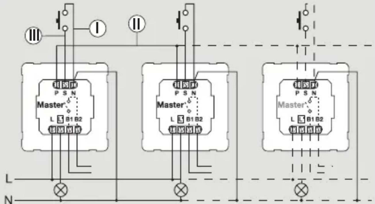
Master/Master COM1 (Fig. 4.4)
Master/Master COM1/COM2 (Fig. 4.5)
A parallel-connected configuration also permits the use of several masters. In this case, each master operates the lighting group in accordance with the level of brightness it measures. All settings are selected at each master as required.
The switched load is spread among the individual masters.
Presence is still detected collectively by all detectors. The presence output (HLK, COM2) can be picked off from any master.
Note:
In a master/master system, inverse switching behaviour may occur on pressing the switch (A) if the IR/HF 180 have different stay-ON times and this has already elapsed for one sensor. If this situation occurs, you must either wait until the stay-ON time elapses or perform a User Reset (RC 5) or Reset (RC 8). When interconnecting IR/HF 180, this risk is reduced by selecting the same settings for control dials and DIP switches.
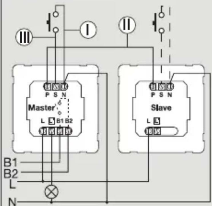
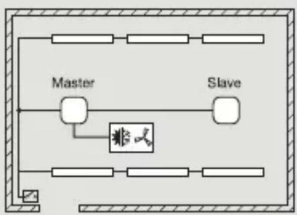
Master/slave (Fig. 4.6.)
The master/slave configuration permits detection of movement in larger rooms (load connected = master, no load = slave). The level of brightness prevailing in the room is only evaluated at the master. The slaves report movements detected to the master.
Two detectors on an external stairwell lighting timer, old building / refurbishment (Fig. 4.7)
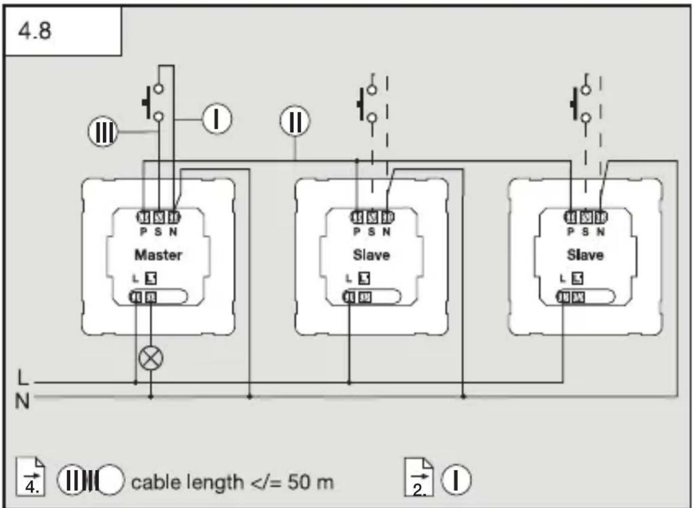
Interconnection with Control PRO sensors (Fig. 4.8)
If the IR 180 / HF 180 is interconnected with a Control PRO Sensor via the P conductor, all switches connected to the wall switch as well as internal switches must be deactivated (Fig. 5.4). If the overall system is to be provided with a switch for manual override, this must be connected to the S input of the Control PRO sensor. The Control PRO Sensor must be the master and the IR 180 / HF 180 the slave.
5. Mounting
- Check all components for damage.
- Do not use the product if it is damaged.
- Select an appropriate mounting location, taking the reach and motion detection into consideration (Fig. 5.1)
Mounting procedure
- Separate the sensor and load module (Fig. 5.2)
- Switch OFF power supply (Fig. 4.1)
- Connect to mains power supply (Fig. 4.2 / 4.3)
- Push load module (H) into the flush box (Fig. 5.3)
- Screw to support ring with box fixing screws (Fig. 5.3)
- Select control dial and DIP switch settings on the sensor module (E) (Fig. 5.4) ( "6. Function")
- Fit the sensor module (E) into the surround (G) and press together with the load module (H) (Fig. 5.5)
- Switch ON power supply (Fig. 5.6)
6. Function
Factory settings for control dials
Reach setting (J): IR 12 m / HF 8 m
Time setting (K): 30 s
Twilight setting (L): Daylight operation
Stay-ON time COM2 15 min
Switch-ON delay COM2 0 min
Reach setting IR (Fig. 5.4 / J)
adjustable in stages
- Control dial set to maximum = max. reach (approx. 12 m)
- Control dial set to minimum = min. reach (approx. 5 m)
Reach setting HF (Fig. 5.4 / J)
Adjustable in stages
- Control dial set to maximum = max. reach (approx. 8 m)
- Control dial set to minimum = min. reach (approx. 1 m)
Time setting (Fig. 5.4 / K)
Adjustable in stages
The chosen stay-ON time can be set to between 30 s and 30 min via the control dial. When the brightness threshold is exceeded, (presence logic), the sensor switches OFF after the stay-ON time expires.
Pulse mode Jl
If the control dial is set to , the unit is in pulse mode, i.e. the output is switched ON for approx. 2 s (e.g. for stairwell lighting timer).
Afterwards, the sensor does not react to movement for approx. 8 s. Day mode is the only mode possible here because of dazzle by light from external sources.
IQ mode (IQ)
If the control dial is set to (IQ), the stay-ON time is self-learning and adjusts dynamically to user behaviour. The time cycle is determined by means of a learning algorithm. The shortest time is 5 min, the longest time 20 min.
Twilight setting (Fig. 5.4 / L)
The chosen response threshold can be set in stages from 2-1000 lux.
- Control dial set to = twilight mode (approx. 2 lux)
- Control dial set to = daylight mode (approx. 1000 lux)
"Example applications" table
DIP switch factory settings
DIP 1 - DIP 5 = OFF
DIP 1 - (NORM./TEST) normal/test mode (Fig. 5.4)
Test mode has priority over all other settings on the sensor switch and is used for verifying proper working order as well for testing the detection zone. Irrespective of the ambient light level, the sensor switch activates the light to stay ON for approx. 5 s in response to movement in the room (blue LED flashes on detecting movement). All user-selected potentiometer settings apply in normal mode (control dials). The sensor switch can also be set by means of the blue LED without any load connected.
The DIP-switch test mode does not end automatically.
DIP 2 - (AUTO./MAN) fully automatic mode / semi-automatic mode (Fig. 5.4)
Fully automatic mode: (AUTO)
Depending on brightness, the light switches on automatically if movement is detected and switches off when the brightness increases or upon expiry of the stay-ON time. The light can be switched ON and OFF manually at any time. This temporarily interrupts the automatic switching function.
Semi-automatic mode: (MAN)
The light only switches OFF automatically. Light is switched ON manually, request light via the switch. It remains ON for the stay-ON time selected.
DIP 3 - (used / not used) (Fig. 5.4)
Selecting the "used" setting activates the integrated switch (A) as well as any switch optionally connected to the S input. Set to "not used", the integrated switch (A) and any switch optionally connected to the S input is deactivated and therefore has no function.
The switch also influences interconnection with the P conductor.
( "4. Electrical connection")
DIP 4 - (ON / ON/OFF) (Fig. 5.4)
In the ON-OFF setting, the light can be switched ON and OFF manually at any time (except in pulse mode: no manual OFF). In the ON setting, light can no longer be switched OFF manually. The stay-ON time starts from the beginning again each time the switch is pressed.
Switch for light function
The function of the integrated switch (A) depends on sensor configuration as well as the current operating situation.
"Light function" table
Twilight setting
| Examples of use Light-level settings | |
| Twilight operation min | |
| Corridors, foyers 1 | |
| Stairs, escalators, moving walkways 2 | |
| Washrooms, toilets, switch rooms, canteens 3 | |
| Sales floor, kindergartens, nursery school rooms, sports halls | 4 |
| Work rooms: offices, conference and meeting rooms, precision assembly activities, kitchens | 5 |
| Working areas requiring good light: laboratory, technical drawing, precision work | >=6 |
| Daylight operation max |
Note: Depending on the mounting location, this setting may need correcting. The light level is measured at the sensor.
Light function
| DIP switch 2 mode | Switch configura- tion DIP switch 4 | Status Switch function | |
| Fully automatic mode | ON / ON-OFF Light | ng is switched OFF | Lighting is switched ON for the stay-ON time selected |
| Fully automatic mode | ON-OFF Lighting is | switched ON | Lighting is switched OFF for the stay-ON time selected and re-triggered on detecting movement (inverse mode / presentation mode) |
| Fully automatic mode | ON Lighting is | switched ON | The stay-ON time se- lected is re-triggered. |
| Semi-automatic mode | ON / ON-OFF Light | ng is switched OFF | Lighting is switched ON for the stay-ON time selected. |
| Semi-automatic mode | ON-OFF Lighting is | switched ON | Lighting is switched OFF until it is next activated. |
| Semi-automatic mode | ON Lighting is | switched ON | The stay-ON time selected is re-trig- gered. |
7. Accessories (optional)
User remote control RC 5 EAN 4007841 592806
Additional functions, RC 5
- Light ON/OFF 4 h
-Userreset - 100 h burn-in
-Presentationmode
Service remote control RC 8 EAN 4007841 559410
Additional functions, RC 8
-Reach adjustment
Time setting CH1/CH2
-ON delay / room surveillance, CH 2
-Test / normal mode
-Twilightsetting
Night-timeoperation
-Daylightoperation
- Teach-IN
- Automatic / manual mode
-Reset
-IQ mode
Smart Remote EAN 4007841 009151
- Control via smartphone or tablet
- Replaces all remote controls
- Download the appropriate app and connect via Bluetooth
8. Disposal
Electrical and electronic equipment, accessories and packaging must be recycled in an environmentally compatible manner.
Do not dispose of electrical and electronic equipment as domestic waste.
EU countries only:
Under the current European Directive on Waste Electrical and Electronic Equipment and its implementation in national law, electrical and electronic equipment no longer suitable for use must be collected separately and recycled in an environmentally compatible manner.
9. Declaration of Conformity
STEINEL Vertrieb GmbH hereby declares that the HF 180 radio equipment type conforms to Directive 2014/53/EU. The full wording of the EU Declaration of Conformity is available for downloading from the following Internet address: www.steinel.de
10. Manufacturer's Warranty
As purchaser, you are entitled to your statutory rights against the vendor. If these rights exist in your country, they are neither curtailed nor restricted by our Warranty Declaration. We guarantee that your STEINEL Professional sensor product will remain in perfect condition and proper working order for a period of 5 years. We guarantee that this product is free from material-, manufacturing- and design flaws. In addition, we guarantee that all electronic components and cables function in the proper manner and that all materials used and their surfaces are without defects.
Making Claims
If you wish to make a claim, please send your product complete and carriage paid with the original receipt of purchase, which must show the date of purchase and product designation, either to your retailer or contact us at STEINEL (UK) Limited, 25 Manasty Road, Axis Park, Orton Southgate, Peterborough, PE2 6UP, for a returns number. For this reason, we recommend that you keep your receipt of purchase in a safe place until the warranty period expires. STEINEL shall assume no liability for the costs or risks involved in returning a product.
For information on making claims under the terms of the warranty, please go to www.steinel-professional.de/garantie
If you have a warranty claim or would like to ask any question regarding your product, you are welcome to call us at any time on our Service Hotline 01733 366700.

| 11. Technical specifications | ||
| Dimensions W × H × D 80 × 80 × 50 mm | ||
| Supply voltage 220-240 ~V / 50/60 HZ | ||
| Sensor system Passive infrared (IR) / high-frequency (HF) | ||
| Reach IR max. 12 m (tangential) / max. 3 m (radial) / HF max. 8 m* | ||
| Angle of coverage 180° | ||
| Output Incandescent / halogen lamp load | 2000 W | |
| Fluorescent lamps, electronic ballast | 1000 W | |
| Fluorescent lamps, uncorrected | 1000 VA | |
| Fluorescent lamps, series-corrected | 400 VA | |
| Fluorescent lamps, parallel-corrected | 500 VA | |
| Low-voltage halogen lamps | 2000 VA | |
| LED < 2 W | 100 W | |
| 2 W < LED < 8 W | 300 W | |
| LED > 8 W | 600 W | |
| Capacitive load | 176 μF | |
| Output, switching output 2 presence (COM 2 only) | max. 230 W / 230 V | |
| max. 1 A (cos φ = 1) for HVAC (heating/ventilation / air-conditioning) | ||
| Light-level setting 10-1000 lux, ∞ / daylight | ||
| Switching output 1 30 s - 30 min, pulse mode (approx. 2 s), Time setting, IQ mode time (automatic adjustment to usage profile) | ||
| Switching output 2 only COM2 for HVAC | Time setting 0 or 10 min switch-ON delay. 5-15 min stay-ON time via (RC) 1 min - 2 h stay-ON time via Smart Remote Automatic room surveillance | |
| Mounting height 1.1 m | ||
| Time setting 30 s - 30 min | ||
| IP rating IP20 | ||
| Temperature range 0°C to 40°C | ||
| * At extreme angles, the reach of the HF 180 is extensively determined by local conditions. | ||
| 12. Troubleshooting | ||
| Malfunction Cause Remedy | ||
| Light does not switch ON | ■ No supply voltage ■ Lux setting too low | ■ Check supply voltage ■ Slowly increase lux set- ting until light switches ON |
| ■ No motion being detected | ■ Ensureunobstructed sensor vision ■ Check detection zone | |
| Light does not switch OFF | Lux setting too high Stay-ON time still effective ■ Interfering heat sources: e.g. fan heater, open doors and windows, pets, light bulb / halo- gen floodlight, moving objects ■ Position Wi-Fi device very close to the sensor | ■ Reduce lux setting ■ Wait until stay-ON time elapses; reduce stay- ON time if necessary ■ Use stickers to mask out stationary sources of interference |
| ■ Increase distance between Wi-Fi device and sensor >3m | ||
| Sensor switches OFF despite persons being present | ■ Stay-ON time too short ■ Light-level threshold too low | ■ Increase stay-ON time ■ Change twilight setting |
| Sensor does not switch OFF quickly enough | ■ Stay-ON time too long | ■ Reduce stay-ON time |
| Sensor does not switch ON quickly enough when approached from the front | ■ Reach is reduced when approached from the front | ■ Install additional sensors ■ Reduce distance between two sensors |
| Sensor does not switch ON when persons are present despite it being dark | ■ Lux setting too low | ■ Sensor deactivated by switch/button? ■ Semi-automatic mode? ■ Increase light-level threshold |
| Switch not working | ■ Switchdeactivated? | ■ Check DIP switch 3 setting |
FR
Master/master COM1/COM2 (afb. 4.5)
DIP 3 - (used / not used) (afb. 5.4)
DIP 4 - (ON / ON/OFF) (afb. 5.4)
Winkels, crèches, scholen, sporthallen 4
DIP 4 - (ON / ON/OFF ) (Hold 5.4)
Master/Master COM1 (ill. 4.4)
Master/Master COM1/COM2 (ill. 4.5)
5 Å R S PRODUSENT GARANTI
Informasjon om hvordan du gjør garantikrav gjeldende finner du på hjemmesiden vår, www.vilan.no Ta gjerne kontakt med oss om du har garantikrav eller sporsmal angåendeproduktet ditt. Du när oss på +47 22 72 50 00.