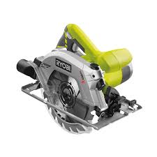
EWS-1266 - Circular saw RYOBI - Free user manual and instructions
Find the device manual for free EWS-1266 RYOBI in PDF.
User questions about EWS-1266 RYOBI
0 question about this device. Answer the ones you know or ask your own.
Ask a new question about this device
Download the instructions for your Circular saw in PDF format for free! Find your manual EWS-1266 - RYOBI and take your electronic device back in hand. On this page are published all the documents necessary for the use of your device. EWS-1266 by RYOBI.
USER MANUAL EWS-1266 RYOBI
Not to use any abrasive wheels.
Ensure that the riving knife is adjusted so that the distance between the riving knife and the rim of the blade is not more than 5mm and the rim of the blade does not extend more than 5mm beyond the lowest edge of the riving knife.
Safety instructions for all saws

DANGER: Keep hands away from cutting area and the blade. Keep your second hand on auxiliary handle, or motor housing. If both hands are holding the saw, they cannot be cut by the blade.
NOTE: For circular saws with 140mm or smaller diameter blades, the "Keep your second hand on auxiliary handle, or motor housing" may be omitted.
- Do not reach underneath the workpiece. The guard cannot protect you from the blade below the workpiece.
- Adjust the cutting depth to the thickness of the workpiece. Less than a full tooth of the blade teeth should be visible below the workpiece.
- Never hold piece being cut in your hands or across your leg. Secure the workpiece to a stable platform. It is important to support the work properly to minimize body exposure, blade binding, or loss of control.
- Hold power tool by insulated gripping surfaces when performing an operation where the cutting tool may contact hidden wiring or its own cord. Contact with a "live" wire will also make exposed metal parts of the power tool "live" and shock the operator.
- When ripping always use a rip fence or straight edge guide. This improves the accuracy of cut and reduces the chance of blade binding.
Always use blades with correct size and shape (diamond versus round) of arbour holes. Blades that do not match the mounting hardware of the saw will run eccentrically, causing loss of control. - Never use damaged or incorrect blade washers or bolt. The blade washers and bolt were specially designed for your saw, for optimum performance and safety of operation.
Further safety instructions for all saws
Causes and operator prevention of kickback:
■ kickback is a sudden reaction to a pinched, bound or misaligned saw blade, causing an uncontrolled saw to lift up and out of the workpiece toward the operator;
- when the blade is pinched or bound tightly by the kerf closing down, the blade stalls and the motor reaction drives the unit rapidly back toward the operator;
If the blade becomes twisted or misaligned in the cut, the teeth at the back edge of the blade can dig into the top surface of the wood causing the blade to climb out of the kerf and jump back toward the operator.
Kickback is the result of saw misuse and/or incorrect operating procedures or conditions and can be avoided by taking proper precautions as given below.
- Maintain a firm grip with both hands on the saw and position your arms to resist kickback forces. Position your body to either side of the blade, but not in line with the blade. Kickback could cause the saw to jump backwards, but kickback forces can be controlled by the operator, if proper precautions are taken.
NOTE: For circular saws with 140 mm or smaller diameter blades, the words "with both hands" may be omitted. - When blade is binding, or when interrupting a cut for any reason, release the trigger and hold the saw motionless in the material until the blade comes to a complete stop. Never attempt to remove the saw from the work or pull the saw backward while the blade is in motion or kickback may occur. Investigate and take corrective actions to eliminate the cause of blade binding.
- When restarting a saw in the workpiece, centre the saw blade in the kerf and check that saw teeth are not engaged into the material. If saw blade is binding, it may walk up or kickback from the workpiece as the saw is restarted.
Support large panels to minimise the risk of blade pinching and kickback. Large panels tend to sag under their own weight. Supports must be placed under the panel on both sides, near the line of cut and near the edge of the panel. - Do not use dull or damaged blades. Unsharpened or improperly set blades produce narrow kerf causing excessive friction, blade binding and kickback.
- Blade depth and bevel adjusting locking levers must be tight and secure before making cut. If blade adjustment shifts while cutting, it may cause binding and kickback.

English
PARTICULAR REQUIREMENTS FOR CIRCULAR SAWS
Use extra caution when making a "plunge cut" into existing walls or other blind areas. The protruding blade may cut objects that can cause kickback.
Safety instructions for saws with lower guard
- Check lower guard for proper closing before each use. Do not operate the saw if lower guard does not move freely and close instantly. Never clamp or tie the lower guard into the open position. If saw is accidentally dropped, lower guard may be bent. Raise the lower guard with the retracting handle and make sure it moves freely and does not touch the blade or any other part, in all angles and depths of cut.
NOTE: Alternate wording may be substituted for "retracting handle".
- Check the operation of the lower guard spring. If the guard and the spring are not operating properly, they must be serviced before use. Lower guard may operate sluggishly due to damaged parts, gummy deposits, or a build-up debris.
Lower guard should be retracted manually only for special cuts such as "plunge cuts" and "compound cuts." Raise lower guard by retracting handle and as soon as blade enters the material, the lower guard must be released. For all other sawing, the lower guard should operate automatically.
NOTE: Alternate wording may be substituted for "retracting handle".
Always observe that the lower guard is covering the blade before placing saw down on bench or floor. An unprotected, coasting blade will cause the saw to walk backwards, cutting whatever is in its path. Be aware of the time it takes for the blade to stop after switch is released.
Additional safety instructions for all saws with riving knife
Use the appropriate riving knife for the blade being used. For the riving knife to work, it must be thicker than the body of the blade but thinner than the tooth set of the blade.
- Adjust the riving knife as described in this instruction manual. Incorrect spacing, positioning and alignment can make the riving knife ineffective in preventing kickback.
Always use the riving knife except when plunge cutting. Riving knife must be replaced after plunge cutting. Riving knife causes interference during
plunge cutting and can create kickback.
For the riving knife to work, it must be engaged in the workpiece. The riving knife is ineffective in preventing kickback during short cuts.
- Do not operate the saw if riving knife is bent. Even a light interference can slow the closing rate of a guard.
DESCRIPTION
- Spindle lock button
- Hex-head bolt
- Spanner
- Outer blade washer
- Lower guard
- Lower guard lever
- Upper guard
- Blade
- Inner blade washer
- Dust nozzle
- Riving knife
- Depth lock knob
- Base plate
- Depth of cut
- Depth scale
- Bevel adjustment knob
- Bevel scale
- Trigger switch
- Safety button
- Line guide
- Depth adjustment lug
- Live Tool indicator
- Laser guide button
- Laser guide
- LED button
- LED light
SPECIFICATIONS
| EWS-1266 | EWS-1366 | |
| Voltage | 230V | 110V/230V |
| Input | 1,250 W | 1,250 W/1,350 W |
| No load speed | 4,500 min-1 | 4,500 min-1 |
| Bore size | 16 mm | 16 mm |
| Blade size | 190mm | 190 mm |
| Cutting capacityat 0° | 66 mm | 66 mm |
| at 45° | 38 mm | 38 mm |
| Bevel scale | 0 – 45° | 0 – 45° |

English
INSTRUCTIONS FOR SAFE HANDLING
The maximum permissible system impedance:
Zmax for EWS-1266 is 0.245 Zref & Zmax for EWS-1366 is 0.252 Zref.
If in doubt, please verify with your local energy-utilitythat the AC outlets in your area do not exceed theabobe values.
STANDARD ACCESSORIES
Saw blade, Parallel fence, Spanner.
APPLICATION
Sawing wood.
NOISE BUILD-UP
Noise (sound pressure level) in the workplace can exceed 85 dB. In this case, sound insulation and hearing protection measures must be taken by the operator.
ASSEMBLY INSTRUCTIONS
BE SURE TO DISCONNECT THE TOOL FROM THE POWER SUPPLY BEFORE ATTACHING OR REMOivating THE SAW BLADE. BE SURE THAT THE TEETH OF THE SAW BLADE ARE POINTING UPWARD AT THE FRONT OF THE TOOL.
ATTACHING AND REMOVING THE BLADE (FIGURES 2, 3, 4, AND 5)
ATTACHING THE BLADE
- Pressing the spindle lock button (1), turn the hex-head bolt (2) with the spanner (3) until the spindle locks. (Fig.2)
- Loosen the hex-head bolt by turning the spanner anticlockwise while pressing the spindle lock button. (Fig.2)
- Remove the hex-head bolt and the outer blade washer (4). (Fig. 2)
- Retract the lower guard (5) back with the lower guard lever (6) as far as possible under the upper guard (7). (Fig. 3)
- Then, attach the saw blade (8) against the inner blade washer (9) on the spindle. Then fit the outer blade washer and the hex-head bolt. (Fig. 3 and 4)
-
Press the spindle lock button again, tighten the hexhead bolt by turning the spanner clockwise while pressing the spindle lock button. (Fig. 5)
-
After tightening the hex-head bolt, release the spindle lock button.
REMOVING THE BLADE
- Pressing the spindle lock button, turn the hex-head bolt with the spanner until the spindle locks.
- Loosen the hex-head bolt by turning the spanner anticlockwise while pressing the spindle lock button.
- Remove the hex-head bolt and the outer blade washer.
- Retract the lower guard back as far as possible under the upper guard, then remove the saw blade.
ADJUSTING THE RIVING KNIFE (FIG. 6)

WARNING!
Do not use saw blades the disk of which is thicker, or the set of which is smaller, then the thickness of the riving knife.
- Ensure that the riving knife is adjusted so that (Fig. 6):
A. The distance between the riving knife (11) and the toothed rim of the saw blade is under 5 mm.
B. The toothed rim does not extend more than 5mm beyond the lower edge of the riving knife.
- The riving knife should always be used except when making a plunging cut in the middle of a workpiece.
ADJUSTING THE DEPTH OF CUT (FIG. 7A, 7B, 8, 9)
- To adjust the depth of cut, loosen the depth adjustment knob (12). (Fig. 7A)
- Slide the base plate (13) to the desired depth using the depth adjustment lug (21) and retighten the knob securely. (Fig. 7B)
- The depth of cut (14) can be determined by the depth scale (15) or by measuring the distance by which the blade protrudes from the base plate. (Fig. 8 and 9)
ADJUSTING THE CUTTING ANGLE (FIG. 10A, 10B)
- The cutting angle may be set to any position between 0^ and 45^ . (Fig. 10A)
- Loosen the bevel adjustment knob (16) at the front of the tool and move the base plate to the desired angle using the bevel scale (17). (Fig.10B)
- Once the angle has been set, be sure to retighten the bevel adjustment knob firmly.

English
TRIGGER SWITCH (FIG. 11)
This tool is started and stopped by squeezing and releasing the trigger switch (18). To prevent the tool from being started accidentally, the trigger can only be operated if the safety button (19) is depressed first. The safety button can be depressed with the thumb leaving the other fingers free to squeeze the trigger switch. It is not necessary to maintain pressure on the safety button once the trigger switch has been depressed.
OPERATING INSTRUCTIONS (FIG. 12)

DANGER!
KEEP HANDS AWAY FROM THE CUTTING AREA WHEN OPERATING THE TOOL. KEEP THE CORD AWAY FROM THE CUTTING AREA AND POSITION IT SO THAT IT WILL NOT GET CAUGHT ON THE WORKPIECE DURING THE CUTTING OPERATION.
When cutting, use steady and even pressure (DO NOT FORCE) in order to obtain a uniform cut. Cut at a speed suited to the workpiece. (Cut slowly if the workpiece is hard.) Inspect the saw blade frequently and replace or sharpen it if dull, to avoid overloading the motor.
CUTTING POSITION (FIG. 13A, 13B)
When cutting a workpiece at 0^ , use point "A" of the base plate line guide (20) and move the saw along the pencilled line you have drawn. When cutting at 45^ , use point "B". This line guide shows an approximate line of cut. Make a sample cut in scrap lumber to determine the actual line of cut.

CAUTION!
When ripping, the rip fence should only touch the workpiece slightly. Do not force.
USING THE LASER GUIDE (FOR EWS-1366 ONLY) (FIG. 14)

WARNING
Do not stare into the laser beam or turn the laser on when the tool is not in use. Failure to do so could result in possible serious personal injury. The laser unit comes from the factory already installed and aligned.
NOTE: Make a trial cut on a piece of scrap to ensure laser is aligned. Adjusting the laser may be necessary.
Mark the line to be cut on the workpiece.
Adjust the depth and angle of the cut as needed.
Switch on the laser beam.
NOTE: Do not touch the blade to the workpiece until the saw has reached maximum speed.
Slowly push the saw forward into the workpiece.
NOTE: Keep the laser beam on the marked line on the workpiece for precision cutting.
Once the cut is complete, allow the saw to come to a complete stop before turning off the laser.
LED WORKLIGHTS (FOR EWS-1366 ONLY) (FIG. 15)
Your saw is equipped with 2 LED WORKLIGHTS (26). These worklight help illuminate the work piece in dimly lit areas and helps when following the cutting line.
ADJUSTING THE LASER GUIDE (FIG. 16)
Adjust the laser angle
- Rotate the screw clockwise to turn the laser beam to right.
- Rotate the screw anti-clockwise to turn the laser beam to left.
Adjust the laser position
Rotate the screw anti-clockwise to shift the beam to right.
- Rotate the screw clockwise to shift the beam to left.
MAINTENANCE
After use, check the tool to make sure that it is in top condition.
We recommended that you take this tool to an Authorised Ryobi Service Centre for a thorough cleaning and lubrication at least once a year.
DO NOT MAKE ANY ADJUSTMENTS WHILE THE MOTOR IS RUNNING.
ALWAYS DISCONNECT THE POWER CORD FROM THE SOCKET BEFORE CHANGING REMOVABLE OR EXPENDABLE PARTS (BLADE, BIT, SANDPAPER, ETC.), LUBRICATING OR WORKING ON THE SAW.
KEEP HANDLES CLEAN AND FREE FROM OIL AND GREASE.

WARNING!
For greater safety and reliability, all repairs should be performed by an Authorised Ryobi Service Centre.
English
LIVE TOOL INDICATOR
This tool features a live tool indicator (22) which illuminates as soon as the tool is connected to the supply. This warns the user that the tool is connected and will operate when the switch is pressed.
ENVIRONMENTAL PROTECTION
Recycle raw materials instead of disposing as waste. The machine, accessories and packaging should be sorted for environmental-friendly recycling.
SYMBOL
The following show the symbols used for the tool. Be sure that you understand their meaning before use.
V. Volts Hz. Hertz .Alternating Current W. Watts no. .No load Speed min-1.Revolutions or reciprocation per minute

Maximum cutting capacity in wood

Double Insulation

Read instruction manual

Recycle raw materials instead of disposing as waste. The machine, accessories and packaging should be sorted for environmental-friendly recycling.

Français
CONSIGNES DE SECURITE SPECIFIQUES AUX SCIES CIRCULAIRES
CHARACTERISTIQUES PRODUIT
STANDAARD ACCESSORIES
- Zmax = 0,245 x Zref for model EWS-1266
- Zmax = 0,252 x Zref for model EWS-1366
INDSTILLING AF SAVEDYBDE
(FIG. 7A, B, 8, 9)
INNSTILLING AV SPALTEKNIVEN (FIG. 6)

ADVARSEL!
HnKoIa He HcNoJIb3yIte a6pa3HBHbIe IINcK.
Поверъ,Тоьбы Делпгльньи HOKьг OTpeунрobан TAK,Тоьбы PACSTOHHNE МжДУ Hm N 3y6bMn Dncka 6blIO MeHbIe 5 MM,ИТоьбы 3у6ьВICTYANII He 6OJIe Yem Ha 5 MM 3a HIXKNI Кай Делпгльного HOJa.
BaxhIe IpaBHJaTexHHKn 6e30NaChocTH IJIa BceX TnIOB IIJI.

OIIACHOCTb: DepKHTe pyKn IoJaIbIhe ot IIIbHorO INcKa H 30HbI paCNIIOBKn. DepKHTecb OHOHpyKo 3a OCHOBHyO pyKOHTky, a DpyTOI -3a BCHOMOrateIbHyIO HIN 3a KApTeP MoToPA. B 3OTmIoJooKeHH pyKn He IOnaJyT B 3OHy paCNIIOBKn HIN Ha TpAeKTopHo paCINHa.
IppHmeeHAne: IJI INCKOBbIX INI J C HnAMeTpOM INIIbHOrO INKcKa MeHJIe HIN PABbIM 140 MM INHCTpyKIIa NJEpKaTbC8I pyroIy PkO3 a BCNtMOrAteJbHyO pyKOrTKU HIN 3a KapTe MOTopo> He IIpHmEHNETc.
He 3aBoIHTe pyKn IIOI 3aIOTOBky: B 3TOM MecTe KOJyX He 3aIIHIIaET IOJIOTHO.
PeryHpye Tny6bHy paacnHa 3aBCHMocHTO ToJIINHbI 3aTOBOKh.Bo BpeMa pacIHIOBKn 3y6bJ DaNcKa He JOJIIXHbI IOJIHOCTbIO BbIXoINTb CHN3Y 3aTOBOKh.
■ HNKOΓA He ČeρχHte 3aRθoTbKy pykoI IHH MeKJy HOr. 3akpenJIte ee Ha yctOuHOBn IOBepxHoCTH. Bo I36ekaHne TpaBM, I3rHbα IINcKa I NtepH KOHTpOJIa HAI INHCTpyMeHOTm IckHIOUHTeIbHO BAckHO IIpaBnIbHO φHKCHPOBATb 3aRθoTbKy.
- IIpn pa6oTe B NOBepxHocTJX, 3a KOtOpbIMN MoKet 6bIb cnpTaHa 3JIeKtponpOBoJka, H pa6oTax, INpn KOTopbIX IHHyp NHTAHnMoKet OKa3aTbCn Ha TpaekToPnn HHCTpyMeHtA, DePknTE HnCTpyMeHr ToIbKO 3a H3OIHpOBaHbHe H NcckOJIb3aIIHe qactn. IIpn CoNPHKoCHOBeHN C npOboJAMn IOJn HAprrjKeHem MetaJIINueCKHe qACTn HnCTpyMeHtA MOryt TJIeKTPH3OBAtCb HIOBJLeYb Yapd TOKOM.
Ipn npapaiJIeJIbHOH paCNIOBKe BceEJa noJIb3yTeCb HnnpaBIAIOUeH npApJIeJIbHOH paCNIOBKn IIN pIpmM6pYcOM. 2TO IOBbICHT TOOHOCT bpaNIIa H npedOTBparHT N3r6 IIINbHOrO JDCka.
HIOJIb3yIeTcB IINCKAMN, HNOxOJIAIIHMn HO pa3Mepy H NO fOpme Hape3Ke BaJIa. NUCNI, He NOxOJIaIIHe BaJIY, Ha KOTOpBI OHN yCTaHOBJIeHbI, 6yUT BpaIaHTbcA HeIPaBUNJIbHO INPbBEyT K NOTEpe KOHTpOI HA IHCTpyMEHTOM.
Hnkorda he noIb3yItecb deΦeKTHbIMn HIN
HeNoDxOJaIHHM BnHTaMH N HeeKamH HIIbHO IuNcKa. IIeKHN BnHTbI INJIbHO IOcKa IINrTOBJeHb CIIeHaJIbHO DIA DAHHo MOeJIIN IIbI, OHN OBeCneHBAOT ONTHMaJIbHYIO 6e3OpAChOCTb H pOn13BOJNTeJIbHOCTb HnCTpymEHTa
IIOHIOHTeJIbHbIe IpaBnJaTexHHKn 6e3OHaChocTH JIA BCEX TINOB IIJI.
PnHnBtOcKoKBnHXIpeDynpexJdEHHe:
OTCKOK BO3HNAKT, KOJIa IIIIbIbI H IINCK 3AkhMaetcI, HETcER HIN HEPOBHO CTOIT; IIIIa pe3Ko OTcKaKNBaET O T 3aOTOTOBKn B CTOPOHy NIOJIb3OBaTeJIa.
Korda IIbIbIbIaNCK 3actpeBaetBpeBe, MToOp IpoOnJIkaeT paOtaTB nOtPacbIbaeT INHbV HnPaPbJIeHHn PpTOHBOJIOJIOXHom HnPaPbJIeHHo BpaIeHHa DnKa, T.E. CTOTOPHY NIOJB3OBATEJIa.
EclnIINbHbnI NCK THeTcN HIn HepBOH cTOnT,ero 3aHnne 3y6bMy MOrT yBe3aTbcB J DepeBo H pe3Ko OTOpOcbH IIyOT 3aTOrOBeKN B CToPOHy NOJIb3ObaTeJIa.
TaKm 6pa3OM,OTCKOK BO3HHkaET Bpe3yIbTaTe HeNpabHbHbHO NcIOJIbO3BaHN HcIePymeta IIN HeNpabHbHbHX yCIOBHN I pOeUepy paCNIIOBKn. OTcKoka MOKHO H36eKaTb, COJIHOJd NEKOTOpbe IpAbaHla.
Держhte плу obemn pykamn,чтобь коюрларовате в сlyае otckoka.Bo Вемя paobotсстсусokу OTпьы,а на ht ecтраektори. Ппг OTсКОЕ плу OTбрасьВаET ha3д,HO OTСКОМЖНО.KOHТРлроваьс,ecJIППЛБЗОВАТь BOTOB K HEMY. Пимешанne:ДЯ плссдпаметрOMпьлHorO ДИСКа мeньше пл paBньIM 140 MM,Инстукйя «ОБEHmpykamn» He пименяETся.
Ecln Dnck 3actprn HnHne0xOJHMo npepBaTb pacnnl Ho KaKoJ-Jn6o pnuHne,OTNCTte Kypok H octabTe HnIy B 3arotOBke, NOka Hnck NIOJHOctBIO he OCTaBOHTc. HKnOrJa He nItaTaeB bHytB HnIy H3 3arotOBKn HnTIaHTyBe ee Ha3ad, NOka Hnck He OCTaHOHJIc8: 3TO MoKe TpNBecTH K OTCKOky. Ecln IIhIbHn Dnck 3aKat, NaHInTe pnuHny 3axHma H npIMnte Heo6xoJHmBle MePbI, YTObI eTo He NOBTOPHIOCb.
IpeKJe Yem 3aynckatb HJy H npOJXkAtb pa60Ty BbPOBnHte HJbHbN dNcK NIO JHHN paCnHJa H y6eHntcB bTom, Tpo ero 3y6bHe KacaIOTc3 3aTOBKn. EcnINck 3aKAT b 3aTOrOBKe, npn 3aYncke HJIbMoKET pON3oHTN OTCOK.
Bo n36eXaHHe 3aXHMa HbHorO dNcKa H onAchocTh OTCKoKa NOIdepKbBaTne IINHHbte 3arotOBKn. IINHHbte 3arotOBKn pOrn6aHOTcnoCobCTBeHHbM BEcom.PacCTabJIte NoIcTbKn I06e CTopoHbI 3arotOBKn PJIOM C JINHHe paCIIHa N y Kpa83arotOBKn.


Pysckn
OCObIe IIPABUNIA TEXHNIKBE30NACHOCTN JIA NCKOBbIX INJI
He noIb3yIteCb NOBpeJdeHbIMn HIN TybIMn HIIbHbIMn dNckamn. IIOxo 3aTOUeHHbe HIN HeNPaBnIbHO yCTaHOBJeHHBe HIIbHbIE dNcKc CdeHaOT ouHb ToKNpacHI. IPhr tOM nCK 6yTe0JIbIE TepTeBC o 3aTOrOBky, IN pCK n3ΓoBa n OTCKOBAO3paCTe.
I IpeH hauaIom pa60tBu npOBepBte 3aTAAK Ky BuHTOB peryHPOBKn rhy6NbHu HnAIOHa. EcIn peryHPOBa KIOLOKeHH NIIbHOrO INCKA H3MeHHTCBO BpEma pa60tBi, INCK MOKET 3aXaTbCS H Bb3BATbOTCOKK.
Bybte oco6o BHHMaTeIbHbI npn Bpe3aHHN B cTneH HpyrHe 3akbItbe IIOckocTn. INCK MOKET HaTOJIHKHYtbcra H HeBNIHMbIe ChapyJN IIpeJMeTbI H Bbl3BaTbOTcKOK.
IpaBnla texHnKb 6e3oNaChocTH JIA 3aunTHoro KoKyuXa
I HepeH hauaTOM pa60tB bceFgA npOBepHHTe, TTO6bI HnKHH 3aHHTbIK KOyXu HOIOCTbHO 3akpBaJI nHbHbHbHd NcK. HnKOrDa HE pa60taHte HIOJ,ecJI HnKHH 3aUHTbIK KOyXe XoHNT CBO6HO HnHe cpa3Y 3aKpbBAeT IIbHbHbN DcK. HnKOrDa He 6IOkpyTe HnKHH 3aUHTbIK KOyX B OTKpBTOM HOIOKeHH. Eclnn IINla cIyuaHNO ynaJa, HnKHH 3aUHTbIK KOyXu INbHoro DnCKa MOI NorHybcN. IIOHNMe HnKHH 3aUHTbIK KOyXs 3a pyuKy H npOBepBe, YTO6bl OH XOINl CBO6OHO H He KacaIcN INbHBOrDncka H npyrHX TeaJIe, He3aBHCmOOT BbICTABLeHHORO Yrla I rIy6HbHIpaCIIIA.
Tt06bI BKJIOUHTb HJH BBYIKJIOUHTb IHCTpyMeHT, HauKMHe HJH OTNcyTHe KypOK (18).Bo H36eKaHne CUYaHOrO 3aNycka HINCTpyMeHTa, KypOK paObaTaet TOJIbKO KoJa HaKaTa KHOJa Ka Ka Ka Ka Ka Ka Ka Ka Ka Ka Ka Ka Ka Ka Ka Ka Ka Ka Ka Ka Ka Ka Ka Ka Ka Ka Ka Ka Ka Ka Ka Ka Ka Ka Ka Ka Ka Ka Ka Ka Ka Ka Ka Ka Ka Ka Ka Ka Ka Ka Ka Ka Ka Ka Ka Ka Ka Ka Ka Ka Ka Ka Ka Ka Ka Ka Ka Ka Ka Ka Ka Ka Ka Ka Ka Ka Ka Ka Ka Ka Ka Ka Ka Ka Ka Ka Ka Ka Ka Ka Ka Ka Ka Ka Ka Ka Ka Ka Ka KaKaKaKaKaKaKaKaKaKaKaKaKaKaKaKaKaKaKaKaKaKaKaKaKaKaKaKaKaKaKaKaKaKaKaKaKaKaKaKaKaKaKaKaKaKaKaKaKaKaKaKaKaKaKaKaKaKaKaKaKaKaKaKaKaKaKaKaKaKaKaKaKaKaKaKaKaKaKaKaKaKaKaKaKaKaKaKaKaKaKaKaKaKaKaKaKaKaKaKaKaKo
INSTALOWANIE I SCIAGNIECIE TARCZY (RYSUNKI 2,3,415)
ZAINSTALOWANIE
INSTALOWANIE I SCIAGNIECIE TARCZY (RYSUNKI 2,3,415)
W CELU WYKONYWANIA CIECIA (RYS. 13A, B)
SAEKETTA MAHAVOTMINE
PYOMIISH TOY I A I A T I K O Y MAXAIPIOY (2x.6)

NPOEIAOIOIHSH!
Mx npouoioleite PIOVLO TO Owua Twv OTOWv Eelv tlo TAnxu n oOvToN uKpOTepn ATO TAnXoc Tou dIoAOTIKoUaXApIou.
TIA NA KOVETE (X. 13A, B)
OTav KoBete ME KAtetn Tn Aa, XpouoTouTo aneio "A" TnC EYKoTnC KAtodynnO nC Tou nElaatoc (20) kai aKolouhote Me To TpiovI OAsn Tg ypaun KAtodynnc Tou oExete Oxediaoei me oLouBt.OTav KoBete OTc 45° XpouoTouTo To aneio B".Autn eeyknt KAtodynnC UToDnAwve kata TpooeYiOn Tn Ypaum KotnC. PpaunatoTouToe m Dakuotkn KOTnOE AxpnoTo KmuAtL Eulou yu v KAtopioTe Tnv payauTkn Ypaun kon

IPOEIOHOH:
'otx xnpoiotoiite Tpokaio 0nhy6,
ev npetel va kouopnta npa eAkpwC
oto akoTO uavtkemuevou. Mn CopiTcE.
XPHSH TOY ANEIZEP OAHFOY (MONOMonteAo Ews-1366) (XX. 14)
\PPOEI OIOIH H
Mny koltate note kateuthetaiav tvn akivaaiecp Kau n the tete note to aeicep oe leitoupyia otav dev xnpaotoiite to npovc H m npon n ts outaoc autnc uopei va enippeo soawatokpauatioo. O aeicep odnyos paoabietai vuaopoloynevo cau euyupammuevoc epyoataka.
Papntnpn: kavte mia dokun o eva xpnto KoumuI wote v a eleyeTe Tnv eUuypamuon Tou IeCep. Av xpeiaetai, puOmuTe to leCep.
All Ryobi products are guaranteed against manufacturing defects and defective parts for a period of twenty-four (24) months from the date stated on the original invoice drawn up by the retailer and given to the end user.
Deterioration caused by normal wear and tear, unauthorised or improper use or maintenance, or overload are excluded from this guarantee as are accessories such as battery packs, light bulbs, blades, fittings, bags, etc. In the event of malfunction during the warranty period, please take the NON-DISMANTLED product, along with the proof of purchase, to your retailer or nearest Authorised Ryobi Service Centre.
This warranty in no way affects your legal rights concerning defective products.

GARANTIE - CONDITIONS
The vibration emission level given in this information sheet has been measured in accordance with a standardised test given in EN 60745 and may be used to compare one tool with another. It may be used for a preliminary assessment of exposure. The declared vibration emission level represents the main applications of the tool. However if the tool is used for different applications, with different accessories or poorly maintained, the vibration emission may differ. This may significantly increase the exposure level over the total working period.
An estimation of the level of exposure to vibration should also take into account the times when the tool is switched off or when it is running but not actually doing the job. This may significantly reduce the exposure level over the total working period. Identify additional safety measures to protect the operator from the effects of vibration such as: maintain the tool and the accessories, keep the hands warm, organisation of work patterns.

AVERTISSEMENT
DECLARATION OF CONFORMITY
We declare under our sole responsibility that this product is in conformity with the following standards or standardized documents:
98/37/EC (until Dec. 28, 2009), 2006/42/EC (from Dec. 29, 2009), 2006/95/EC, 2004/108/EC.
EN55014-1; EN55014-2; EN61000-3-2; EN61000-3-3; EN60745-1; EN60745-2-5; EN50366

DECLARATION DE CONFORMITE
98/37/EC (tll 28. December 2009),2006/42/EC (fra 29.deember 2009),2006/95/EC,2004/108/EC,
EN55014-1; EN55014-2; EN61000-3-2; EN61000-3-3; EN60745-1; EN60745-2-5; EN50366

3AABJEHNE O COOTBETCTBHH CTAHAPTAM
Mfo Cbeo 3BETBECHNBOCTHO B3AJIEM, YTOHACOTIIAHIPOJIKIIN COOTBEHTBET HIXKE CJELOYIOHM HOPMAH JOKCMYEMAT:
98/37/EC (do 28 de6a0b0 2009 r.), 2006/42/EC (nocne 29 de6a0b0 2009 r.), 2006/95/EC, 2004/108/EC.
EN55014-1; EN55014-2; EN61000-3-2; EN61000-3-3; EN60745-1; EN60745-2-5; EN50366

DEKLARACJA ZGODNOSCJI
Name/Title: Brian Ellis / Vice President - Engineering
Signature:

Dec. 05, 2009
Technical File at
Name of company: TTI EMEA
Address: MEDINA HOUSE, FIELDHOUSE LANE, MARLOW, BUCKS, SL7 1TB, UNITED KINGDOM
Name/Title: Carl Jefferies / Head of Ryobi Product Marketing
Signature:

Trademarks:
The use of the trademark Ryobi is pursuant to a license granted by Ryobi Limited.


Rev: 03
04-12-2009