
GWS 21230 JHV Professional - Angle grinder BOSCH - Free user manual and instructions
Find the device manual for free GWS 21230 JHV Professional BOSCH in PDF.



| Product type | Angle grinder |
| Brand | Bosch |
| Model | GWS 21230 JHV Professional |
| Maximum wheel diameter | 230 mm |
| No-load speed | 6500 rpm |
| Input voltage | 220–230 V |
| Sound level | 90 dB(A) (intensity) / 103 dB(A) (noise level) |
| Hand-arm vibration | 5.5 m/s² |
| Main functions | Cutting, grinding, brushing |
| Protection guard | Adjustable guard with quick-release or tightening screw |
| Auxiliary handle | Vibration damping (VIBRATION CONTROL) |
| Spindle lock | Yes, lock button |
| Switch | On/Off with lock-off |
| Head rotation | In 90° increments (4 positions) |
| Handle orientation | 90° left or right |
| Starting current limitation | Yes (type J) |
| Maintenance | Clean the cooling vents regularly |
| Compatible accessories | Grinding/cutting discs, sanding plates, cup brushes, cup grinding wheels, hand guard |
| Workable materials | Metal, stone (dry) |
| After-sales service | Bosch France, Belgium, Switzerland (see manual) |
Frequently Asked Questions - GWS 21230 JHV Professional BOSCH
User questions about GWS 21230 JHV Professional BOSCH
0 question about this device. Answer the ones you know or ask your own.
Ask a new question about this device
Download the instructions for your Angle grinder in PDF format for free! Find your manual GWS 21230 JHV Professional - BOSCH and take your electronic device back in hand. On this page are published all the documents necessary for the use of your device. GWS 21230 JHV Professional by BOSCH.
USER MANUAL GWS 21230 JHV Professional BOSCH
GWS 21-180/230 (J)H GWS 24-180/230 (J)B GWS 24-180/230 (J)H GWS 26-180/230 (J)B GWS 26-180/230 (J)H Professional
BOSCH
Ideas that work.
Operating instructions
Dr. Egbert Schneider Dr. Eckerhard Strötgen Senior Vice President Head of Product Engineering Certification
Robert Bosch GmbH, Power Tools Division
| Weight without cable, approx. [kg] 5.1 |
| Protection class |
- The values given are valid for nominal voltages [U] of 230/240 V. For lower voltages and models for specific countries, these values can vary.
Please observe the order number of your machine. The trade names of the individual machines may vary. Inrush currents cause short-time voltage drops. Under unfavourable power supply conditions, other equipment may be affected. If the system impedance of the power supply is lower than 0.25 Ohm, disturbances are unlikely to occur.
Machine Elements For Your Safety
The numbering of the machine elements refers to the representation of the machine on the graphics page.
While reading the operating instructions, unfold the graphics page for the machine and leave it open.
1 Thread for auxiliary handle (3x) 2 Spindle lock button 3 On/Off switch 4 Auxiliary handle 5 Grinder spindle 6 Protection guard 7 Adjustment screw 8 Clamping lever 9 Mounting flange with O-ring 10 Grinding/cutting disc 11 Clamping nut 12 Quick clamping nut* 13 Clamping screw 14 Coded projection 15 Guard, grinding cup 16 Grinding cup 17 Two-pin spanner for clamping nut 18 Hand guard 19 Spacer discs 20 Rubber sanding plate 21 Sanding sheet 22 Round nut 23 Cup brush 24 Diamond cutting disc 25 Cutting guide with dust extraction protection guard 26 Handle unlocking button 27 Handle 28 Cutting grinder stand Not all of the accessories illustrated or described are included as standard delivery.

Working safely with this machine is possible only when the operating and safety information are read completely and the instructions contained therein are strictly followed. In addition, the
general safety notes in the enclosed booklet must be observed. Before using for the first time, ask for a practical demonstration.
Wear protective glasses and hearing protection. ■Wear additional protection equipment for your safety, such as protective gloves, sturdy shoes, hard hat and apron. The dust that is produced while working can be detrimental to health, inflammable or explosive. Suitable safety measures are required. Examples: Some dusts are regarded as carcinogenic. Use suitable dust/chip extraction and wear a dust respirator. Dust from light alloys can burn or explode. Always keep the workplace clean, as blends of materials are particularly dangerous. If the mains cable is damaged or cut through while working, do not touch the cable but immediately pull the mains plug. Never use the machine with a damaged cable. Connect machines that are used in the open via a residual current device (RCD) with an actuating current of 30 mA maximum. Do not operate the machine in rain or moisture. ■When working with the machine, always hold it firmly with both hands and provide for a secure stance. ■Secure the workpiece. A workpiece clamped with clamping devices or in a vice is held more secure than by hand. Always direct the cable to the rear away from the machine. Always switch the machine off and wait until it has come to a standstill before placing it down. For power outage or when the mains plug is pulled, unlock the On/Off switch immediately and turn it to the off position. This prevents uncontrolled restarting. The machine must be used only for dry cutting/grinding. For all work with the machine, the auxiliary handle must be mounted.
Hold the power tool only by the insulated gripping surfaces, when performing an operation where the cutting tool may run into hidden wiring or its own cord. Contact with a "live" wire will make exposed metal parts of the tool "live" and shock the operator. Use appropriate detectors to determine if utility lines are hidden in the work area or call the local utility company for assistance. Contact with electric lines can lead to fire and electric shock. Damaging a gas line can lead to explosion. Penetrating a water line causes property damage or may cause an electric shock. For work with grinding or cutting discs, the protection guard 6 must be mounted. For work with the rubber sanding plate 20 or with the cup brush 23/disc brush/flap disc, the hand guard 18 (accessory) is to be mounted. Use dust extraction when working with stone. The vacuum cleaner must be approved for masonry dust. When cutting stone, use the cutting guide. Do not work with materials containing asbestos. Use only grinding tools with a permissible speed at least as high as the no-load speed of the machine. Check grinding tools before use. The grinding tool must be properly mounted and turn freely. Perform a test run for at least 30 seconds without load. Do not use damaged, out-of-round or vibrating grinding tools. Protect the grinding tool from impact, shock and grease. Apply the machine to the workpiece only when switched on. Keep hands away from rotating grinding tools. Pay attention to the direction of rotation. Always hold the machine so that sparks and grinding dust fly away from the body. When grinding metal, flying sparks are produced. Take care that no persons are endangered. Due to danger of fire, no combustible materials should be located in the vicinity (spark flight zone).
Be careful when cutting grooves, e.g. in structural walls: See Information on Structures. Blocking the cutting disc leads to jerking reaction forces on the machine. In this case switch off the machine immediately. Pay attention to the dimensions of the grinding disc. The mounting hole diameter must fit the mounting flange 9 without play. Do not use reducers or adapters. Never use cutting discs for rough grinding. Do not exert any lateral pressure on the cutting discs. Observe the manufacturer's instructions for mounting and using grinding tools. Caution! The grinding tool runs on after the machine is switched off. Do not clamp the machine in a vice. Never allow children to use the machine. Bosch is only able to ensure perfect operation of the machine if the original accessories intended for it are used.
Intended Use
The machine is intended for cutting, roughing and brushing metal and stone materials without using water. For cutting stone, a cutting guide is required.
Information on Structures
Slots in structural walls are subject to the Standard DIN 1053, Part 1 or country-specific regulations.
These regulations are to be observed under all circumstances. Before beginning work, consult the responsible structural engineer, architects, or the construction supervisor.

Mounting the Protective Devices
■ Before any work on the machine itself, pull the mains plug. ■ For work with grinding or cutting discs, the protection guard 6 must be mounted.
Protection Guard with Locking Screw
The coded projection 14 on the protection guard 6 ensures that only a guard that fits the machine type can be mounted.
Loosen the clamping screw 13, if necessary.
Place the protection guard 6 with coded projection 14 into the coded groove on the spindle collar of the machine head and rotate to the required position (working position).
The closed side of the protection guard 6 must always point to the operator.
Tighten clamping screw 13.
Protection Guard with Quick Clamp

The protection guard is preadjusted to the diameter of the spindle collar. If required, the tightening tension of the clamping bracket can be changed by tightening or loosening the adjustment screw 7. Always ensure that the protection guard 6 is seated tightly on the spindle collar.
Open the clamping lever 8.
Place the protection guard 6 on the spindle collar of the machine head and turn to the required position (working position).
To fasten the protection guard 6, close the clamping lever 8.
The closed side of the protection guard 6 must always point to the operator.
Auxiliary Handle
For all work with the machine, the auxiliary handle must be mounted.
Screw the auxiliary handle 4 into the head of the machine according to the working method.
Vibration-dampening Auxiliary Handle
VIBRATION CONTROL
The vibration-dampening auxiliary handle reduces the vibrations, making operation more comfortable and secure.

Do not make any alterations to the auxiliary handle.
Do not continue to use an auxiliary handle if it is damaged.
Hand Guard
For work with the rubber sanding plate 20 or with the cup brush 23/disc brush/flap disc, the hand guard 18 (accessory) is to be mounted. The hand guard 18 is fastened with the auxiliary handle 4.
Mounting the Grinding Tools
Before any work on the machine itself, pull the mains plug.

Use only grinding tools with a permissible speed at least as high as the no-load speed of the machine.
Grinding and cutting discs become very hot while working; do not touch until they have cooled.
Clean the grinder spindle and all parts to be mounted. For clamping and loosening the grinding tools, lock the grinder spindle 5 with the spindle lock button 2.
Actuate the spindle lock button 2 only when the grinder spindle is at a standstill!
Grinding/Cutting Disc
Pay attention to the dimensions of the grinding disc. The mounting hole diameter must fit the mounting flange 9 without play. Do not use reducers or adapters.
When using a diamond cutting disc, take care that the direction-of-rotation arrow on the diamond cutting disc and the direction of rotation of the machine (direction-of-rotation arrow on the machine head) agree.
For mounting, see the illustration page.
Screw on the clamping nut 11 and tighten with the two-pin spanner (see Section "Quick-clamping Nut").
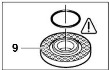
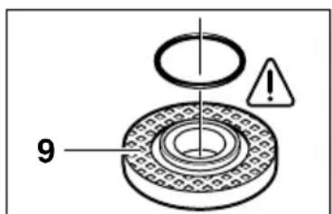
An O-ring (plastic part) is inserted in the mounting flange 9 around the spigot.
If the O-ring is missing or is damaged, it must in all cases be replaced (Order No. 1600210039) before the mounting flange 9 is mounted.

After mounting the grinding tool and before switching on, check that the grinding tool is correctly mounted and that it can turn freely.
Flap Disc
Depending on the application, remove the protection guard 6 and mount the hand guard 18. Place the special mounting flange 9 (accessory, Order No. 2 605 703 028) and the flap disc on the grinder spindle 5. Screw on the clamping nut 11 and tighten with the two-pin spanner.
Rubber Sanding Plate 20
Depending on the application, remove the protection guard 6 and mount the hand guard 18.
Before mounting the rubber sanding pad 20, place the 2 spacers 19 onto the grinding spindle.
For mounting, see the illustration page.
Screw on the round nut 22 and tighten with the two-pin spanner.
Cup Brush 23/Disc Brush
Depending on the application, remove the protection guard 6 and mount the hand guard 18.
The grinding tool must be able to be screwed onto the grinding spindle 5 until it rests firmly against the grinder spindle flange at the end of the grinder spindle threads. Tighten with an open-end spanner.
Grinding Cup

When working with grinding cups, use the special guard 15.
The grinding cup 16 should always protrude from the guard 15 only as far as absolutely necessary for the work to be performed in each case.
Adjust the guard 15 to this distance.
For mounting, see the illustration page.
Screw on the clamping nut 11 and tighten with the fitting offset two-pin spanner 17.
Quick Clamping Nut SDS-e/ie
Instead of the clamping nut 11, the quick-clamping nut 12 (accessory) can be used. Grinding tools can then be mounted without using tools.
The quick-clamping nut 12 may be used only for grinding and cutting discs.
Use only a flawless, undamaged quick-clamping nut 12.
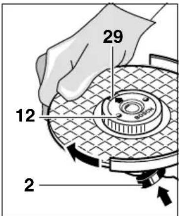
When screwing on, take care that the side with printing does not point to the grinding disc. The arrow must point to the index mark 29.
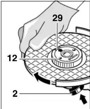
Lock the grinder spindle with the spindle lock button 2. Tighten the quick-clamping nut by forcefully turning the grinding disc in the clockwise direction.
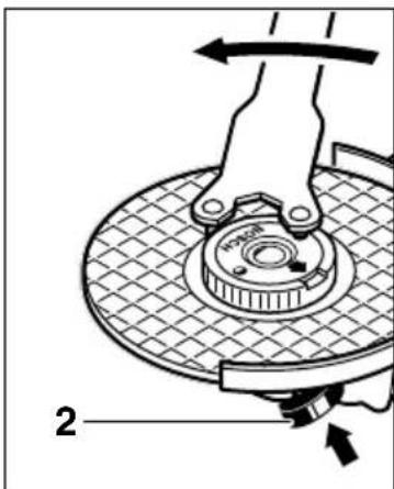
A properly tightened undamaged, quick-clamping nut can be loosened by hand turning the knurled ring in anticlockwise direction.
Never loosen a tight quick-clamping nut with pliers but use a two-pin spanner. Insert the two-pin spanner as shown in the illustration.
Approved Grinding Tools
All grinding tools mentioned in this operating manual instruction can be used.
The permissible speed [rpm] or the circumferential speed [m/s] of the grinding tools used must at least match the values given in the table.
Therefore, always observe the permissible rotational/circumferential speed on the label of the grinding tool.
| max. [mm] [mm] | d [rpm] [m/s] | ||||
| D | b | ||||
| b D | 180 | 8 | 22.2 | 8 500 | 80 |
| 230 | 8 | 22.2 | 6 500 | 80 | |
| D | 180 | - | - | 8 500 | 80 |
| 230 | - | - | 6 500 | 80 | |
| b D | 100 | 30 M | 14 8 500 | 0 45 | |
Initial Operation
Observe correct mains voltage: The voltage of the power source must agree with the voltage specified on the nameplate of the machine. Equipment marked with 230V can also be connected to 220V.
Switching On and Off
To start the machine, press the On/Off switch 3 forward and then down.
To lock-on, push the pressed On/Off switch 3 further forwards.
To switch off the machine, release the On/Off switch 3 or push and release it then.
Switch version without lock (country-specific):
To start the machine, press the On/Off switch 3 forward and then down.
To switch off the machine, release the On/Off switch 3.

Test run!
Check the grinding tool before use. The grinding tool must be properly mounted and rotate freely. Perform a test run of at least 30 seconds without load. Do not use damaged, out-of-round or vibrating grinding tools.

Reduced Starting Current (Type J)
As a result of soft starting, a 13 A fuse is adequate.

A machine without reduced starting current requires higher fuse protection (use at least a 13 A time-delay fuse).
Operating Instructions
Clamp the workpiece if it does not remain stationary due to its own weight. Do not strain the machine so heavily that it comes to a standstill. Grinding and cutting discs become very hot while working; do not touch until they have cooled.
Rough Grinding

The best roughing results are achieved when setting the machine at an angle of 30° to 40°. Move the machine back and forth with moderate pressure. In this manner, the workpiece will not become too hot, does not discolour and no grooves are formed.

Never use a cutting disc for roughing.
Flap Disc
With the flap disc (accessory), curved surfaces and profiles (contour sanding) can be worked.
Flap discs have a considerably higher service life than sanding sheets, lower noise level and lower sanding temperatures.
Cutting
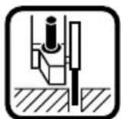
When cutting, do not press, jam or oscillate the machine. Work with moderate feed, adapted to the material being machined.
Do not reduce the speed of running down cutting discs by applying sideward pressure.
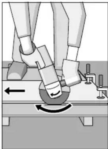
The direction in which the cutting is performed is important.
The machine must always work in an up-grinding motion. Therefore, never move the machine in the other direction! Otherwise, the danger exists of it being pushed uncontrolled out of the cut.
Grinder Stand
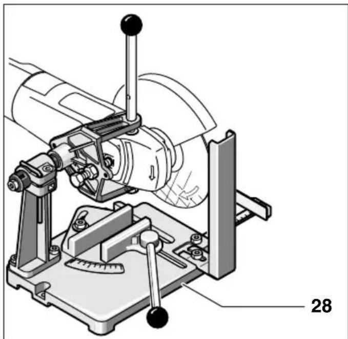
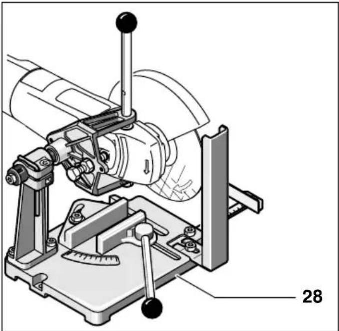
With the grinder stand 28 (accessory), workpieces can be cut at angles of 0 to 45 degrees at the same lengths.
The safety notes and operating instructions in the respective operating instructions manual of the angle grinder are to be strictly observed. Use only original Bosch grinder stands.
Cutting Stone
The machine must be used only for dry cutting/grinding.

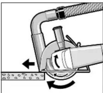
It is best to use a diamond cutting disc. As a safety measure against jamming, use the cutting guide 25 with the special dust extraction protection guard.
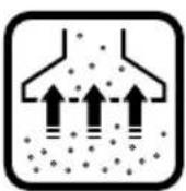
Operate the machine with dust extraction only. In addition, wear a dust mask.
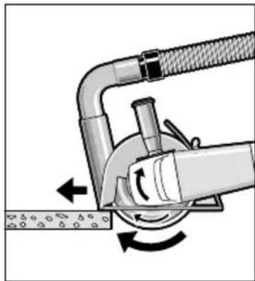
The vacuum cleaner must be approved for the extraction of masonry dust.
Bosch provides suitable vacuum cleaners.
Switch on the machine and place the front part of the cutting guide on the workpiece.
Slide the machine with moderate feed, adapted to the material to be worked (Figure).
For cutting especially hard material, e.g., concrete with high pebble content, the diamond cutting disc can overheat and become damaged as a result. This is clearly indicated by circular sparking, rotating with the diamond cutting disc.
In this case, interrupt the cutting process and allow the diamond cutting disc to cool by running freely at no-load speed for a short time.
Noticeable decreasing work progress and circular sparking are indications of a diamond cutting disc that has become dull. Briefly cutting into abrasive material (e.g., lime-sand brick) can sharpen the disc.
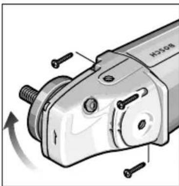
Rotating the Machine Head
Before any work on the machine itself, pull the mains plug.
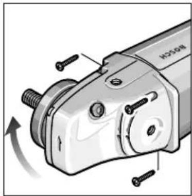
The machine head can be rotated with respect to the machine housing in 90° steps. In this manner, the On/Off switch can be brought to an advantageous handling position for special working situations, e.g., for cutting work
with the cutting guide 25/cutting grinder stand 28 (accessory) or for left-handed persons.
Unscrew completely the four screws.
Rotate the machine head carefully and without removing from the housing to the new position.
Screw in the screws again and tighten.
Turning the Machine Handle (GWS 24/26-180/230 (J)B)
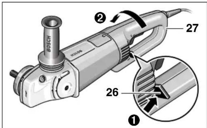
The handle 27 can be turned with respect to the motor housing by 90° either to the left or right. This allows for the On/Off switch to be positioned more conveniently for certain working situations, e.g., for cutting work with the cutting guide/ grinder stand (accessories) and for left-handers.
Pull the handle unlocking button 26 firmly in the direction of the arrow (1), turning the handle 27 at the same time to the desired position (2) until it engages. The figure shows the handle 27 turned by 90°.
The handle unlocking button 26 and the On/Off switch 3 have a safety interlock.
The machine cannot be switched on if the handle 27 is not engaged in one of the three possible positions.
The handle 27 cannot be unlocked if the On/Off switch 3 is locked.
Maintenance and Cleaning
Before any work on the machine itself, pull the mains plug.

For safe and proper working, always keep the machine and the ventilation slots clean.

In extreme working conditions, conductive dust can accumulate in the interior of the machine when working with metal. The protective insulation of the machine can be degraded. The use of a stationary extraction system is recommended in such cases as well as frequently blowing out the ventilation slots and installing a residual current device (RCD).
If the machine should fail despite the care taken in manufacturing and testing procedures, repair should be carried out by an after-sales service centre for Bosch power tools.
In all correspondence and spare parts orders, please always include the 10-digit order number given on the nameplate of the machine.
WARNING! Important instructions for connecting a new 3-pin plug to the 2-wire cable.
The wires in the cable are coloured according to the following code:
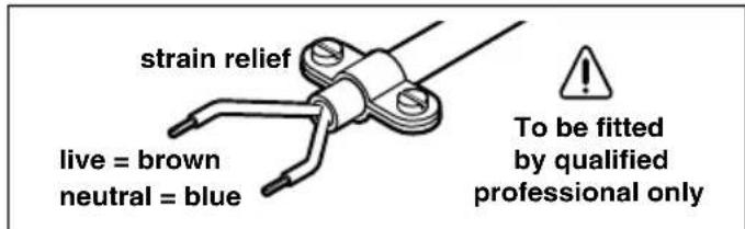
Do not connect the blue or brown wire to the earth terminal of the plug.
Important: If for any reason the moulded plug is removed from the cable of this machine, it must be disposed of safely.
Environmental Protection

Recycle raw materials instead of disposing as waste
The machine, accessories and packaging should be sorted for environmental-friendly recycling.
These instructions are printed on recycled paper manufactured without chlorine.
The plastic components are labelled for categorized recycling.
Noise/Vibration Information
Measured values determined according to EN 50 144.
Typically the A-weighted noise levels of the machine are: Sound pressure level: 90 dB (A); sound power level: 103 dB (A).
Wear hearing protection!
The typically weighted acceleration is 5.5m / s2
When using the vibration-dampening auxiliary handle, the hand-arm vibration at the auxiliary handle is typically below 2.5m / s2
After-Sales Service and Customer Assistance
Our after-sales service responds to your questions concerning maintenance and repair of your product as well as spare parts. Exploded views and information on spare parts can also be found under:
www.bosch-pt.com
Our customer consultants answer your questions concerning best buy, application and adjustment of products and accessories.
Great Britain
Robert Bosch Ltd. (B.S.C.)
P.O.Box 98
Broadwater Park
North Orbital Road
Denham
Uxbridge
UB 95HJ
Tel. Service: +44 (0844) 736 0109
Fax: +44 (0844) 736 0146
Australia, New Zealand and Pacific Islands
Robert Bosch Australia Pty.Ltd.
Power Tools
Locked Bag 66
Clayton South VIC 3169
Customer Contact Center
Inside Australia:
Phone: +61 (01300) 307 044
Fax: +61 (01300) 307 045
Inside New Zealand:
Phone: +64 (0800) 543 353
Fax: +64 (0800) 428 570
Outside AU and NZ:
Phone: +61 (03) 9541 5555
www.bosch.com.au
Declaration of Conformity
We declare under our sole responsibility that this product is in conformity with the following standards or standardization documents: EN 50 144 according to the provisions of the directives 89/336/EEC, 98/37/EC.
Dr. Egbert Schneider Dr. Eckerhard Strötgen
Senior Vice President Head of Product
Engineering Certification
Robert Bosch GmbH, Power Tools Division
Subject to change without notice
Technical Specifications
| Meuleuse angulaire GWS 21-180 H Professional GWS 21-230 H Professional GWS 24-180 B Professional GWS 24-180 JB Professional GWS 24-180 JB Professional GWS 24-180 JB Professional GWS 24-180 B Professional GWS 24-180 B Professional GWS 24-180 B Professional GWS 24-180 B Professional GWS 24-180 B Professional GWS 24-180 B Professional GWS 24-180 B Professional GWS 24-180 B Professional GWS 24-180 B Professional GHS 2000 GHS 2000 GHS 2000 GHS 2000 GHS 2000 GHS 2000 GHS 2000 GHS 2000 GHS 2000 GHS 2000 GHS 2000 GHS 2000 GHS 2000 GHS 21/II / II / II GHS 21/II / II / II GHS 21/II / II / II GHS 21/II / II / II GHS 21/II / II / II GHS 21/II / II / II GHS 21/II / II / II GHS 21/II / II / II GHS 21/II / II / II GHS GHS GHS GHS GHS GHS GHS GHS GHS GHS GHS GHS GHS GHS GHS GHS GHS GHS GHS GHS GHS GHS GHS GHS GHS GHS GHS GHS GHS GHS GHS GHS GHS GHS | |
| Rétérence 0 601 851 0.. 0 601 852 0.. 0 601 853 0.. | |
| Avec limitation du courant de démarrage GWS 21-180 JH Professional GWS 21-230 JH Professional GWS 24-180 B Professional GWS 24-230 H Professional GWS 24-230 H Professional GWS 24-230 H Professional GWS 24-230 H Professional GWS 24-230 H Professional GWS 24-230 H Professional GWS 24-230 H Professional GWS 24-230 H Professional GWS 24-230 H Professional GHS 2000 GHS 2000 GHS 2000 GHS 2000 GHS 2000 GHS 2000 GHS 2000 GHS GHS GHS GHS GHS GHS GHS GHS GHS GHS GHS GHS GHS GHS GHS GHS GHS GHS GHS GHS GHS GHS GHS GHS GHS GHS GHS GHS GHS GHS GHS GHS GHS | Rétérence 0 601 851 0.. 0 601 852 0.. 0 601 853 0.. |
| Puisance absorbée nominale* [W] 2 100 2 100 2 400 | |
| Puisance débitée [W] 1 350 1 350 1 700 | |
| Régime à vide [tr/min] 8 500 6 500 8 500 | |
| Diamètre des meules, max. [mm] 180 230 180 | |
| Filet de la broche M 14 M 14 M 14 | |
| Poids sans câble de secteur, env. [kg] 4,3 4,3 5,1 | |
| Classe de protection / II / II / II | |
| Meuleuse angulaire GWS 24-180 H Professional GWS 24-230 B Professional GWS 24-230 H Professional GWS 24-230 H Professional GWS 24-230 H Professional GWS 24-230 H Professional GWS 24-230 H Professional GWS 24-230 H Professional GWS 24-230 H Professional GWS 24-230 H Professiona Professional GWS 24-230 B Professional GWS 24-230 B Professional GWS 24-230 B Professional GWS 24-230 B Professional GWS 24-230 B Professional GWS 24-230 B Professional GWS 24-230 B Professional GWS 24-230 B Professional GWS 24-230 B Professional GHS 2000 GHS 2000 GHS 2000 GHS 2000 GHS 2000 GHS GHS GHS GHS GHS GHS GHS GHS GHS GHS GHS GHS GHS GHS GHS GHS GHS GHS GHS GHS Clique de protection / II / II / II / II | |
| Rétérence 0 601 851 0.. 0 601 852 0.. 0 601 853 4.. | |
| Avec limitation du courant de démarrage GWS 21-180 JH Professional GWS 24-180 B Professional GWS 24-230 B Professional GWS 24-230 B Professional GWS 24-230 B Professional GWS 24-230 B Professional GWS 24-230 B Professional GWS 24-230 B Professional GWS 24-230 B Professional GWS 24-230 B Professiona Professional GWS 24-230 B Professional GWS 24-230 B Professional GWS 24-230 B Professional GWS 24-230 B Professional GWS 24-230 B Professional GWS 24-230 B Professional GWS 24-230 B Professional GWS 24-230 A B B B B B B B B B B B B B B B B B B B B B B B B B B B B B B B B B B B B B B B B B B B B B B B B B B GHS GHS GHS GHS GHS GHS GHS GHS GHS GHS GHS GHS GHS GHS GHS GHS GHS GHS GHS GHS GHS GHS GHS GHS GHS GHS GHS GHS GHS GHS GHS GHS GHS |
Robert Bosch (France) S.A.S.
Dr. Egbert Schneider Dr. Eckerhard Strötgen Senior Vice President Head of Product Engineering Certification
Robert Bosch GmbH, Power Tools Division
| Amoladora GWS 21-180 H Profesor GWS 21-230 H Professional GWS 24-180 B Professional GWS 24-180 JB Professional GWS 24-180 JB Professional GWS 24-180 B Professional GWS 24-180 B Professional GWS 24-180 B Professional GWS 24-180 B Professional GWS 24-180 B Professional GWS 24-180 B Professional GWS 24-180 B Professional GWS 24-180 B Professional GWS 24- JB Professional GWS 24-230 H Professional GWS 24-230 H Professional GWS 24-230 H Professional GWS 24-230 H Professional GWS 24-230 H Professional GWS 24-230 H Professional GWS 24-230 H Professional GWS 24-230 H Professional GWS 24- JB Professional GWS 24-230 JB Professional GWS 24-230 JB Professional GWS 24-230 JB Professional GWS 24-230 JB Professional GWS 24-230 JB Professional GWS 24-230 JB Professional GWS 24-230 JB Professional GWS 24-230 JB Professional GWS 24- JB Professional GWS 24-230 JB Professional GWS 24-230 JB Professional GWS 24-230 JB Professional GWS 24-230 JB Professional GWS 24-230 JB Professional GWS 24-230 JB Professional GWS 24-231 B Professional GWS 24-230 B Professional GWS 24-230 B Professional GWS 24-230 B Professional GWS 24-230 B Professional GWS 24-230 B Professional GWS 24-230 B Professional GWS 24-230 B Professional GWS 24-230 B Professional GWS 236- JB Professional GWS 236-230 H Professional GWS 236-230 H Professional GWS 236-230 H Professional GWS 236-230 H Professional GWS 236-230 JB Professional GWS 236-230 JB Professional GWS 236-230 JB Professional GWS 236-230 JB Professional GWS 236-230 JB Professional GWS 236-230 JB Professional GWS 236-230 JB Professional GWS 236-230 JB Professional GWS 236-230 JB Professional GWS 236-230 JB Professional GWS 236-230 JB Professional GWS 236-230 JB Professional GWS 236-230 JB Professional GWS 236-230 JB Professional GWS 236-230 JB Professional C. R. S. Con limitación de amolar, máx. [mm] 180 230 230 Rosca del husillo M 14 M 14 M 14 M Peso sin cable de red, aprox. [kg] 5,1 5,1 5,1 Clase de protección / II / II / II Amoladora GWS 24-180 H Professional GWS 24-230 B Professional GWS 24-230 B Professional GWS 24-230 B Professional GWS 24-230 B Professional GWS 24-230 B Professional GWS 24-230 B Professional GWS 24-230 B Professional GWS 24- JB Professional GWS 24-230 B Professional GWS 24-230 B Professional GWS 24-230 B Professional GWS 24-230 B Professional GWS 24-230 B Professional GWS 24-230 B Professional GWS 24-230 B Professional GWS 24 Professional GWS 24-230 B Professional GWS 24-230 B Professional GWS 24-230 B Professional GWS 24-230 B Professional GWS 24-230 B Professional GWS 24-230 B Professional GWS 24-230 B Professional GWS 24 |
Robert Bosch Argentina Industrial S.A.
Av. Cordoba 5160
Senior Vice President Head of Product
Engineering Certification

Robert Bosch GmbH, Power Tools Division
Mounting abrasive tools
Unplug the power cord before all work on the device.

Dr. Egbert Schneider Dr. Eckerhard Strötgen Senior Vice President Head of Product Engineering Certification
Robert Bosch GmbH, Power Tools Division
Dr. Egbert Schneider Dr. Eckerhard Strötgen Senior Vice President Head of Product Engineering Certification
ppa.
Robert Bosch GmbH, Power Tools Division
Snelspanmoer SDS-elic
Senior Vice President Head of Product
Engineering Certification
ppa.
Robert Bosch GmbH, Power Tools Division
Bosch Service Center
For el-vaerktoj
Telegrafvej 3
2750 Ballerup
Tel. Service Center: +45 (04489) 8855
Fax: +45 (04489) 87 55
E-Mail: vaerktoej@dk.bosch.com
Overensstemmelses-erklaring
Dr. Egbert Schneider Dr. Eckerhard Strötgen Senior Vice President Head of Product Engineering Certification
Robert Bosch GmbH, Power Tools Division
Dr. Egbert Schneider Dr. Eckerhard Strötgen Senior Vice President Head of Product Engineering Certification
Robert Bosch GmbH, Power Tools Division
Changes reserved
| Tekniske data | ||||
| Vinkelsliper GWS 21-180 H | Professional | GWS 21-230 H | GWS 24-180 B | |
| Bestillingsnummer 0 601 851 0.. 0 601 852 0.. 0 601 853 0.. | ||||
| Med startström-begrensning | GWS 21-180 JH | GWS 21-230 JH | GWS 24-180 JB | |
| Professional | Professional | Professional | ||
| Bestillingsnummer 0 601 851 9.. 0 601 852 9.. 0 601 853 9.. | ||||
| Opptatt effekt* [W] 2 100 2 100 2 400 | ||||
| Avgitt effekt [W] 1 350 1 350 1 700 | ||||
| Tomgangsturtall [min -1] 8 500 6 500 8 500 | ||||
| Slipskive-diameter, max. [mm] 180 230 180 | ||||
| Slipspindelgjenge M 14 M 14 M 14 | ||||
| Vekt uten | ||||
| Iedning, ca. [kg] 4,3 | 4,3 | 5,1 | ||
| Beskyttelsesklasse | / II | / II | / II | |
| Vinkelsliper GWS 24-180 H | Professional | GWS 24-230 B | GWS 24-230 H | |
| Professional | Professional | |||
| Bestillingsnummer 0 601 853 4.. 0 601 854 0.. 0 601 854 4.. | ||||
| Med startström-begrensning | GWS 24-230 JB | GWS 24-230 JH | ||
| Professional | Professional | |||
| Bestillingsnummer | 0 601 854 9.. 0 601 854 5.. | |||
| Opptatt effekt* [W] 2 400 2 400 2 400 | ||||
| Avgitt effekt [W] 1 700 1 700 1 700 | ||||
| Tomgangsturtall [min -1] 8 500 6 500 6 500 | ||||
| Slipskive-diameter, max. [mm] 180 230 230 | ||||
| Slipspindelgjenge M 14 M 14 M 14 | ||||
| Vekt uten | ||||
| Iedning, ca. [kg] 5,1 | 5,1 | 5,1 | ||
| Beskyttelsesklasse | / II | / II | / II | |
| Vinkelsliper GWS 26-180 B | Professional | GWS 26-180 H | GWS 26-230 B | GWS 26-230 H |
| Professional | Professional | Professional | ||
| Bestillingsnummer 0 601 855 0.. 0 601 855 4.. 0 601 856 0.. 0 601 856 4.. | ||||
| Med startström-begrensning | GWS 26-180 JB | GWS 26-230 JB | GWS 26-230 JH | |
| Professional | Professional | Professional | ||
| Bestillingsnummer 0 601 855 9.. | 0 601 856 9.. 0 601 856 5.. | |||
| Opptatt effekt* [W] 2 600 2 600 2 600 2 600 | ||||
| Avgitt effekt [W] 1 800 1 800 1 800 1 800 | ||||
| Tomgangsturtall [min -1] 8 500 8 500 6 500 6 500 | ||||
| Slipskive-diameter, max. [mm] 180 180 230 230 | ||||
| Slipspindelgjenge M 14 M 14 M 14 M 14 | ||||
| Vekt uten | ||||
| Iedning, ca. [kg] 5,1 | 5,1 | 5,1 | 5,1 | |
| Beskyttelsesklasse | / II | / II | / II | / II |
Senior Vice President Head of Product
Engineering Certification
Robert Bosch GmbH, Power Tools Division
Dr. Egbert Schneider Dr. Eckerhard Strötgen Senior Vice President Head of Product Engineering Certification
Robert Bosch GmbH, Power Tools Division
Dr. Egbert Schneider Dr. Eckerhard Strötgen Senior Vice President Head of Product Engineering Certification
i.v. MucSy
Robert Bosch GmbH, Power Tools Division
TnpouεToδikaiωaαλayωv
| Teknik veriler | ||||
| Avuc taşlama GWS 21-180 H | Professional | GWS 21-230 H | GWS 24-180 B | |
| Sipariş no. 0 601 851 0.. 0 601 852 0.. 0 601 853 0.. | Professional | Professional | ||
| İk hareket akimi sinirlandirmalı | GWS 21-180 JH Professional | GWS 21-230 JH Professional | GWS 24-180 JB Professional | |
| Sipariş no. 0 601 851 9.. 0 601 852 9.. 0 601 853 9.. | ||||
| Anma,giris,gucü*[W] 2 100 2 100 2 400 | ||||
| Çişi,gucü[W] 1 350 1 350 1 700 | ||||
| Bos,taki devir sayişi[/dak] 8 500 6 500 8 500 | ||||
| Taşlama diski capi, maks.[mm] 180 230 180 | ||||
| Taşlama miliDMI M 14 M 14 M 14 | ||||
| Ağrilişi,şebeke kablosu olmadan,yak.[kg] 4,3 4,3 5,1 | ||||
| Koruma sinifi | ☐/II | ☐/II | ☐/II | |
| Avuc taşlama GWS 24-180 H | Professional | GWS 24-230 B | GWS 24-230 H | |
| Professional | Professional | |||
| Sipariş no. 0 601 853 4.. 0 601 854 0.. 0 601 854 4.. | ||||
| İk hareket akimi sinirlandirmalı | GWS 24-230 JB | GWS 24-230 JH | ||
| Professional | Professional | |||
| Sipariş no. | 0 601 854 9.. 0 601 854 5.. | |||
| Anma,giris,gucü*[W] 2 400 2 400 2 400 | ||||
| Çişi,gucü[W] 1 700 1 700 1 700 | ||||
| Bos,taki devir sayişi[/dak] 8 500 6 500 6 500 | ||||
| Taşlama diski capi, maks.[mm] 180 230 230 | ||||
| Taşlama miliDMI M 14 M 14 M 14 | ||||
| Ağrilişi,şebeke kablosu olmadan,yak.[kg] 5,1 5,1 5,1 | ||||
| Koruma sinifi | ☐/II | ☐/II | ☐/II | |
| Avuc taşlama GWS 26-180 B | Professional | GWS 26-180 H | GWS 26-230 B | GWS 26-230 H |
| Professional | Professional | Professional | ||
| Sipariş no. 0 601 855 0.. 0 601 855 4.. 0 601 856 0.. 0 601 856 4.. | ||||
| İk hareket akimi sinirlandirmalı | GWS 26-180 JB Professional | GWS 26-230 JB Professional | GWS 26-230 JH Professional | |
| Sipariş no. 0 601 855 9.. | 0 601 856 9.. 0 601 856 5.. | |||
| Anma,giris,gucü*[W] 2 600 2 600 2 600 2 600 | ||||
| Çişi,gucü[W] 1 800 1 800 1 800 1 800 | ||||
| Bos,taki devir sayişi[/dak] 8 500 8 500 6 500 6 500 | ||||
| Taşlama diski capi, maks.[mm] 180 180 230 230 | ||||
| Taşlama miliDMI M 14 M 14 M 14 | ||||
| Ağrilişi,şebeke kablosu olmadan,yak.[kg] | 5,1 | 5,1 | 5,1 | 5,1 |
| Koruma sinifi | ☐/II | ☐/II | ☐/II | ☐/II |
Bosch San. ve Tic. A.S.
Ahi Evran Cad. No:1 Kat:22
Polaris Plaza
80670 Maslak/Istanbul
Customer Service: +90 (0212) 335 06 66
Customer Service Line: +90 (0212) 335 07 52
Declaration of Conformity
Senior Vice President Head of Product Engineering Certification

Robert Bosch GmbH, Power Tools Division
Robert Bosch Sp.z o.o.
Dr. Egbert Schneider Dr. Eckerhard Strötgen Senior Vice President Head of Product Engineering Certification
ppa.
Robert Bosch GmbH, Power Tools Division
Service Center PT
K Vapence 1621/16
692 01 Mikulov
Tel. +420 (519) 305 700
Fax: +420 (519) 305 705
E-Mail: servis.naradi@cz.bosch.com
www.bosch.cz
C Declaration of Conformity
Senior Vice President Head of Product Engineering Certification
i.v. Mno7gcu
Robert Bosch GmbH, Power Tools Division
Subject to change without notice
Technical data
| Uhlová brúska GWS 21-180 H | GWS 21-230 H | GWS 24-180 B | ||
| Professional | Professional | Professional | Professional | |
| Objednévacie Čísló 0 601 851 0.. 0 601 852 0.. 0 601 853 0.. | ||||
| S obmedzovačom | GWS 21-180 JH | GWS 21-230 JH | GWS 24-180 JB | |
| rozbehového | Professional | Professional | Professional | |
| prúdu | ||||
| Objednévacie Čísló 0 601 851 9.. 0 601 852 9.. 0 601 853 9.. | ||||
| Menovitý príkon* [W] 2 100 2 100 2 400 | ||||
| Výkon [W] 1 350 1 350 1 700 | ||||
| Počet | ||||
| vořnobežných | ||||
| obrátok | [miñ-1] 8 500 6 500 8 500 | |||
| Priemer brúsnych | ||||
| kotúčov, max. | [mm] 180 230 180 | |||
| Závit brúsneho | ||||
| vretena | M 14 M 14 M 14 | |||
| Hmotnost bez sietovej šnúry, cca. | [kg] 4,3 4,3 5,1 | |||
| Ochranná trieda / II / II / II ☑ | ☐ | ☐ | ||
| Uhlová brúska GWS 24-180 H Professional | GWS 24-230 B Professional | GWS 24-230 H Professional | |
| Objednévacie Čísló 0 601 853 4.. 0 601 854 0.. 0 601 854 4.. | |||
| S obmedzovačom rozbehového | GWS 24-230 JB Professional | GWS 24-230 JH Professional | |
| prúdu | |||
| Objednévacie Čísló 0 601 854 9.. 0 601 854 5.. | |||
| Menovitý príkon* [W] 2 400 2 400 2 400 | |||
| Výkon [W] 1 700 1 700 1 700 | |||
| Počet vořnobežných obrátok | [miñ-1] 8 500 6 500 6 500 | ||
| Priemer brúsnych kotúčov, max. | [mm] 180 230 230 | ||
| Závit brúsneho vretena | M 14 M 14 M 14 | ||
| Hmotnost bez siete病变j šnúry, cca. | [kg] 5,1 5,1 5,1 | ||
| Ochranná trieda / II / II / II ☑ | ☐ | ☐ | |
| Uhlová brúsa GWS 26-180 B | GWS 26-180 H | GWS 26-230 B | GWS 26-230 H | ||
| Professional | Professional | Professional | Professional | Professional | |
| Objednámavacie Čísló 0 601 855 0.. 0 601 855 4.. 0 601 856 0.. 0 | 601 856 4.. | ||||
| S obmedzovačom rozbehového prúdu | GWS 26-180 JB Professional | GWS 26-230 JB Professional | GWS 26-230 JH Professional | ||
| Objednámavacie Čísló 0 601 855 9.. 0 601 856 9.. 0 601 856 5.. | |||||
| Menovitý príkon* [W] 2 600 2 600 2 600 2 600 Výkon [W] 1 800 1 800 1 800 1 800 | |||||
| Počet vořnobežných obratok [min-1] | 8 500 8 500 6 500 6 500 | ||||
| Priemer brúsnych kotučov, max. [mm] | 180 | 180 | 230 | 230 | |
| Závit brúsneho vretena | M 14 | M 14 | M 14 | M 14 | |
| Hmotnost bez sieťovej šnúry, cca. [kg] | 5,1 | 5,1 | 5,1 | 5,1 | 5,1 |
| Ochranná trieda | [II / II] | [II / II] | [II / II] | [II / II] | [II / II] |
Dr. Egbert Schneider Dr. Eckerhard Strötgen Senior Vice President Head of Product Engineering Certification

Robert Bosch GmbH, Power Tools Division
Dr. Egbert Schneider Dr. Eckerhard Strötgen Senior Vice President Head of Product Engineering Certification

Robert Bosch GmbH, Power Tools Division
With order number GWS 21-180 JH GWS 21-230 JH GWS 24-180 JB Professional Professional Professional
Order number 0 601 851 9.. 0 601 852 9.. 0 601 853 9..
Rated power input [W] 2100 2100 2400
Power output [W] 1350 1350 1700
No-load speed [min-1] 8500 6500 8500
Wheel diameter, max. [mm] 180 230 180
Number of revolutions
idle speed [min-1] 8500 6500 8500
Circle diameter, max. [mm] 180 230 180
Weight without cable
Plate, OK. [kg] 4, 3.4, 3.5, 1
Degree of protection
Against shocks
Electric shock /II/II/II
Angle grinder GWS 24-180 H, GWS 24-230 B, GWS 24-230 H Professional
Machine
Order number 0 601 853 4.. 0 601 854 0.. 0 601 854 4..
With reduced starting current GWS 24-230 JB GWS 24-230 JH Professional
Order number 06018549.. 06018545..
Requirement
Power,
Nominal [W] 2400 2 400 2 400
Output
Power [W] 1700 1700 1700
Speed
at no load [rpm] 18500 6500 6500
Diameter
of the grinding
wheel, max. [mm] 180 230 230
Thread
of the spindle
M14 M14 M14
Weight without cable
and plug, approx. [kg] 5.1 5.1 5.1
Protection class
against moisture
Illustrated component parts
The numbering of the instrument elements is done according to the illustration on the page with illustrations.
Please open the fold-out page with the illustration of the electric power tool and keep it open while you read the operating instructions.
1 Thread for mounting the auxiliary handle (3x) 2 Spindle lock button 3 Switch 4 Auxiliary handle 5 Spindle collar 6 Protective cap 7 Guide pin 8 Clamping lever 9 Flange screws with O-ring 10 Grinding wheel for rough grinding/cutting wheel* 11 Tension nut
12 Quick-clamping nut *SDS-click 13 Clamping screw 14 Dust protection cap 15 Protective cap for the grinding wheel guard* 16 Grinding wheel guard* 17 Special wrench for the tension nut* 18 Additional handle for protection* 19 Intermediate washers* 20 Rubber pad for grinding wheel 21 Abrasive sheet* 22 Round nut* 23 Guard plate 24 Diamond cutting wheel* 25 Guide rails with protective cap for dust extraction 26 Handle lock button 27 Handle 28 Cutting station with cutting wheel
- Not all of the illustrated or described accessories are included in the standard delivery.


For your safety
Safe operation of the device is only possible after you have fully read the operating instructions and the safety instructions.
Strictly follow the instructions given there. Additionally, the general safety instructions in the enclosed brochure must be followed. Before first use of the tool, you must receive practical instruction from an instructor.
Wear protective goggles and a dust mask. Also wear protective gloves, sturdy footwear, and a helmet. Dust generated during work can be harmful to health, flammable, or explosive. Appropriate protective measures must be taken. For example, some types of dust are carcinogenic. Provide for dust and chip extraction, wear a dust respirator. Light metal dust can be combustible or explosive. Keep the workplace clean, as mixtures of materials are particularly dangerous. If the power cord or extension cord is damaged during work, do not touch the cord, but immediately unplug the mains plug from the socket. Never use a power tool with a damaged cord. When working outdoors, power tools should be connected via a residual current circuit breaker with a maximum tripping current of 30 mA. Do not use the power tool in rain or damp weather. During work, always hold the tool firmly with both hands and ensure a stable stance. Secure the workpiece. A workpiece held in a clamping device or in a vise is held more securely than in your hand. Always guide the cord away from the tool. Before you put the tool down, switch it off and wait until it has come to a complete stop. When interrupting the power supply or after pulling the mains plug from the socket, immediately release the lock
of the switch and set it to the "Off" position. This prevents uncontrolled starting of the tool.
It is permitted to use the tool only with dry cutting (without cooling). Work with the device only with the additional handle mounted. Hold power tools only by the insulated gripping surfaces, as the working tool may come into contact with hidden wiring or its own power cord. Contact with a live wire can put voltage on the metal parts of the tool and lead to electric shock. Use suitable metal detectors to locate hidden supply systems or consult the local utility company. Contact with a power line can lead to fire and electric shock. Damage to a gas pipe can lead to an explosion, and damage to a water pipe can lead to property damage and electric shock. When working with a grinding or cutting wheel, a protective guard must be installed. When working with a rubber-backed or fiber-reinforced grinding wheel, or a diamond cutting wheel, a hand guard (accessory) must be mounted. For working on stone, use the dust extraction accessory. The dust extractor must be approved for stone dust extraction. For cutting stone, use the guide rail. It is not permitted to process materials containing asbestos. Use only the grinding tool whose permitted maximum speed is not less than the maximum no-load speed of the device. Check the grinding tool before use. The grinding tool must be mounted without defects and must rotate freely. Perform a test run of the grinding tool at no-load for at least 30 seconds. Do not use damaged, non-circular, or vibrating grinding tools.
Power tools must be protected from impacts and from oil entering them. Only operate the tool when it is in contact with the workpiece. Do not touch the rotating grinding tool with your hands. Observe the direction of rotation. Always hold the tool so that sparks and grinding dust fly away from the operator's body. When grinding with grinding wheels, there is a risk of kickback. Ensure that no one is endangered. Due to the risk of fire (in the spark zone), no flammable materials may be nearby. Be careful when cutting slots/grooves, for example, in load-bearing walls: observe the information in the section on statics. ■If kickback occurs due to the cutting wheel, the tool develops a jerky reaction. In such a case, switch off the tool immediately. Observe the dimensions of the grinding wheels. There must be no gap between the diameter of the hole in the grinding/cutting wheel and the outer diameter of the centering collar of the mounting flange (see figure 9). Do not use adapters or reducers. Under no circumstances may cutting wheels be used for rough (heavy-duty) grinding. Do not subject cutting wheels to lateral force. Follow the manufacturer's instructions for mounting and using the grinding tool. Caution! The grinding wheel continues to rotate for a while after the tool is switched off. ■Do not clamp the tool in a vise. Never allow children to use the power tool. ■The manufacturer guarantees flawless functioning of the power tool only when using the original accessories intended for this power tool.
Intended use
The tool is intended for cutting, rough grinding, and edge trimming of metal and masonry materials without the use of water (i.e., dry). When cutting, a guide rail must be used as prescribed.
Information on statics
Cutting slots/grooves in load-bearing walls is subject to the provisions of DIN (EN) 1053, part 1, or specific regulations established for individual countries.
These regulations must be observed without fail. Before starting work, consult the responsible structural engineer, architect, or competent construction management.

Mounting the protective devices
Before starting maintenance work on the power tool, disconnect the mains plug from the socket. Work with a grinding wheel for rough (heavy-duty) grinding or with a cutting wheel is only permitted when the protective guard 6 is mounted.
Protective guard with clamping screw
Thanks to the coding lug 14 on the protective guard 6, mounting of a protective guard that does not fit this type of tool is excluded.
If necessary, loosen the clamping screw 13.
Place the protective guard 6 with the coding lug 14 into the coding groove on the collar of the spindle on the tool head and turn it to the required (working) position.
The closed side of the protective guard 6 must always face the operator.
Tighten the clamping screw 13.
Protective guard with quick-release fastener

The protective cap must be pre-tightened to the diameter of the spindle neck. If necessary, the clamping force of the clamping unit can be changed by loosening or tightening the pre-tightening screw 7. In doing so, always pay attention to the secure fastening of the protective cap 6 on the spindle neck.
Open the clamping lever 8.
Place the protective cap 6 onto the neck of the spindle of the tool and turn it to the required (working) position.
To secure the protective cap 6, clamp the clamping lever 8.
The closed protective cap 6 must always be facing the operator.
Additional handle
Work with the tool only with the additional handle mounted.
Depending on the work to be performed, set the additional handle 4 in the appropriate position relative to the tool head.
Additional handle with vibration damping
VIBRATION
CONTROL
The additional handle with vibration damping allows working with a low vibration level, making the work more pleasant and safer.

No modifications to the additional handle are permitted.
Further use of a damaged additional handle is not permitted.
Device for hand protection
Before working with the angle grinder with the grinding disc, cutting disc, or flap disc, it is necessary to mount the protective guard for hands 18 (accessory). The protective guard for hands 18 is secured using the additional handle.
Installing the grinding tool
Before any technical maintenance or adjustment of the power tool, disconnect the mains plug from the socket.

Use only grinding tools whose permissible operating speed is not lower than the maximum no-load speed of the tool. Grinding discs for rough grinding (grinding) and cutting discs heat up strongly during work; therefore, do not touch them with your hands until they have cooled down.
Clean the grinding spindle and all parts to be mounted. To secure and release the grinding tool, use the spindle lock button to lock the grinding spindle 5.
Press the spindle lock button 2 only when the grinding spindle has come to a complete stop!
Rough grinding (grinding) disc / cutting disc
Observe the dimensions of the grinding discs. There must be no gap between the hole diameter of the grinding/cutting disc and the outer diameter of the centering collar of the mounting flange. Do not use reducing rings or adapters.
When using a diamond cutting disc, ensure that the arrow on the diamond cutting disc indicating the direction of rotation matches the direction of rotation of the spindle (indicated by the arrow on the tool head).
Assembly: see page with figure.
Press the locking lever 11 and tighten it using the wrench inserted into the two holes in the lever (see section 'Quick-release lever').
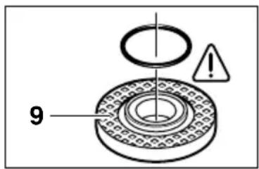
In the mounting flange 9, around the centering collar, an O-ring (a ring of circular cross-section) is inserted (part made of synthetic material).
If the O-ring is missing or damaged, it must be replaced (part number for ordering the O-ring: 1 600 210 039) before mounting the mounting flange 9.

After mounting the grinding tool, check it before switching on the tool. The grinding tool must be correctly mounted and must rotate freely.
Grinding disc with holes (segmented grinding disc)
Depending on the type of work being performed, if necessary, remove the protective cap 6 and install the hand guard device 18. The special mounting flange 9 (accessory, order number 2 605 703 028) and the rubber sanding disc must be mounted on the sanding spindle 5. Press the locking lever 11 and tighten it using the special wrench, which is inserted into the two end holes.
Rubber sanding disc 20
Depending on the type of work being performed, if necessary, remove the protective cap 6 and install the hand guard device 18.
Before mounting the rubber sanding disc 20, first slide the two intermediate washers 19 onto the sanding spindle.
Assembly: see page with figure.
Press the circular lever 22 and tighten it using the special wrench, which is inserted into the two end holes.
Washer 23/Disc 2
Depending on the type of work being performed, if necessary, remove the protective cap 6 and install the hand guard device 18.
Tighten the nut until it is snug, but do not overtighten. Use the wrench to tighten.
Do not loosen the quick-release lever with pliers under any circumstances, but
Use the special wrench, which is inserted into the two end holes. Insert the wrench as shown in the figure.
Starting current limiting (for J)
Thanks to the soft start of the device, a 16 A fuse is sufficient.

For devices without a starting current limiting system, a fuse with a higher current rating is required (install a fuse, for example, 16 A, time-delay).
Application instructions
If the item being processed is not securely held, it must be secured against the action of its own weight.
Do not load the power tool until it has come to a stop.
Fiber discs (flap discs) and grinding discs become very hot during operation; therefore, do not touch them until they have cooled down.
Roughing (flap) disc 1000
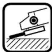
When roughing with a flap disc, the best results are achieved if the tool is guided over the workpiece at an angle of between 30° and 40°. With moderate pressure, perform
back-and-forth movements with the tool. This prevents excessive heating and discoloration of the workpiece, and prevents the formation of grooves.

Under no circumstances may cutting discs be used for roughing (flap disc) work.
Fiber discs ("flap" grinding discs)
The fiber disc (accessory) also allows processing of convex surfaces and profiles (grinding along contours).
The service life of fiber discs is much longer than that of sheets of abrasive paper; in addition, when using fiber discs, the noise level is lower and the grinding temperature is lower.
Cutting with a grinding disc
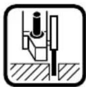
When cutting with a cutting disc, do not press on the tool, do not tilt it, and do not perform oscillating movements. Work at a moderate feed rate,
appropriate to the workpiece material.
Cutting discs that continue to rotate by inertia after the tool is switched off must not be braked by pressing them against any object from the side.
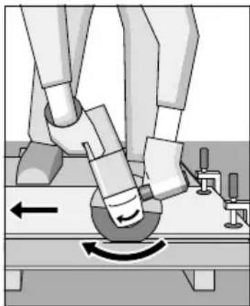
The direction of cutting is an important factor. The tool must always move in the opposite direction to the feed; therefore, the tool must not be worked from the wrong direction! Otherwise, there is a risk of uncontrolled kickback.
Stationary cutting/grinding machine with diamond cutting wheel
The use of the stationary cutting/grinding machine with diamond cutting wheel 28 (accessory) allows cutting workpieces of the same length at an angle from 0° to 45°.
It is necessary to strictly follow the safety instructions and instructions for working with the tool, contained in the corresponding manual and in the operating instructions for the stationary cutting/grinding machine with diamond cutting wheel. Use only original stationary cutting/grinding machines with diamond cutting wheels produced by the company.
Cutting stone
The device may only be used for cutting/grinding dry (without cooling).

It is recommended to use a diamond cutting/grinding wheel. To prevent jamming
Use the guide rail 25 with a special dust extraction hood. Use the device only with a mounted dust extraction device for dust. Additionally, wear a dust respirator.
The vacuum cleaner must be approved for stone dust extraction. The company offers suitable vacuum cleaners.
Switch on the tool and place its front part on the guide rails on the workpiece.
Move the tool with moderate feed, corresponding to the workpiece material (see figure).
When cutting particularly hard workpiece material, for example concrete with a high content of gravel, the diamond cutting/grinding wheel may
overheat and come out of the holder. A clear sign of this is the appearance of sparks together with the diamond cutting/grinding wheel in the form of ring sparks.
In this case, interrupt the cutting process and let the diamond cutting wheel run at idle speed for a while.
A noticeable decrease in the temperature of the working process and the disappearing ring sparks are signs of a dull diamond cutting/grinding wheel. By performing cuts on small sections of abrasive material (for example, on sand-lime brick), the diamond cutting/grinding wheel can be sharpened.
Fully tighten the four screws.
Turn the knob, without removing it from the body, carefully rotate it to a new position.
Tighten the screws again and secure them.
If the switch is locked, handle 27 will not open.
Maintenance and cleaning
Before starting maintenance work on the power tool, disconnect the mains plug from the socket.

To ensure high-quality and reliable operation, always keep the power tool and ventilation slots clean.

Under extreme working conditions when processing metal, conductive dust may accumulate inside the power tool. This can damage the protective insulation of the power tool. In such cases, it is recommended to use a stationary dust extraction system, frequently blow out the ventilation slots, and connect the tool via a residual current device (RCD).
If the power tool, despite careful manufacturing and testing methods, fails, repair should be entrusted to an authorized service workshop for power tools of the Bosch company.
Please always specify the 10-digit order number according to the type plate of the device in all inquiries and orders for spare parts.
Disposal

Recycling of raw materials instead of waste disposal
Packaging, power tools that have reached the end of their service life, accessories, and attachments should be handed in for environmentally friendly recycling of waste.
This operating manual is printed on paper made from recycled materials.
For sorting waste for recycling, parts made of synthetic materials are marked accordingly.
620017, Yekaterinburg
Tel.: +7 (0343) 3658674
Tel.: +7 (0343) 3 78 77 56
Fax: +7 (0343) 3 78 79 28
E-Mail: rbru.pt_asa_ek@ru.bosch.com
Belarus
ACU yn-18
220064, Minsk, ul. Kursatova, 7
Tel.: +375 (017) 2 10 29 70
Fax: +375 (017) 207 04 00
Limited liability company
With exclusive liability we
declare that this product
conforms to the following standards
and normative documents:
EH (European Norms) 50 144 according to
the provisions of Directive 89/336/EEC
(European Economic Community), 98/37/EC.
Dr. Egbert Schneider Dr. Eckerhard Strötgen
Senior Vice President Head of Product
Engineering Certification
Robert Bosch GmbH, Power Tools Division
We reserve the right to make changes.
Technical specifications
| Kутoba шліфмаша | GWS 21-180 H Professional | GWS 21-230 H Professional | GWS 24-180 B Professional |
| Homep дя Замоblastени 0 601 851 0.. 0 601 852 0.. 0 601 | GWS 21-180 JH Professional | GWS 21-230 JH Professional | GWS 24-180 JB Professional |
| 3 Perúliobavahm núckoboro | GWS 21-180 JH Professional | GWS 21-230 JH Professional | GWS 24-180 JB Professional |
| струмy | |||
| Homep дя Замоblastени 0 601 851 9.. 0 601 852 9.. 0 601 | GWS 21-180 JH Professional | GWS 21-230 JH Professional | GWS 24-180 JB Professional |
| Hominaьha сpoхиванa noTuχнICTb* [Вт] 2 100 2 100 2 400 | |||
| Kopисна noTuχнICTb [Вт] 1 350 1 350 1 700 | |||
| швацICTb холostOTO xódu [XB. -1] | 8 500 6 500 8 500 | ||
| Ø shiíþubalhoro | |||
| круг, мас. | [MM] 180 230 180 | ||
| Рizьба шліфувально | |||
| шпindela M 14 M 14 M 14 | |||
| Bara 6e3 kašelio, | |||
| близко [кг] 4,3 4,3 5,1 | |||
| Клас зхису / II | /II | /II | /II |
| Kутoba шліфмаша | GWS 24-180 H Professional | GWS 24-230 B Professional | GWS 24-230 H Professional |
| Homep дя Замоblastени 0 601 853 4.. 0 601 854 0.. 0 601 | GWS 24-230 JB Professional | GWS 24-230 JH Professional | |
| 3 Perúliobavahm núckoboro | |||
| струмy | |||
| Homep дя Замоblastени | 0 601 854 9.. 0 601 854 5.. | ||
| Hominaьha сpoхиванa | |||
| noTuχнICTb* [Вт] 2 400 2 400 2 400 | |||
| Kopисна noTuχнICTb [Вт] 1 700 1 700 1 700 | |||
| швацICTb холostOTO xódu [XB. -1] | 8 500 6 500 6 500 | ||
| Ø shiíþubalhoro | |||
| круг, мас. | [MM] 180 230 230 | ||
| Рizьба шліфувально | |||
| шпindela M 14 M 14 M 14 | |||
| Bara 6e3 kašelio, | |||
| близко [кг] 5,1 5,1 5,1 | |||
| Клас зхису / II | /II | /II | /II |
| Кутoba шліфмаша | GWS 26-180 B Professional | GWS 26-180 H Professional | GWS 26-230 B Professional | GWS 26-230 H Professional |
| Homep DLЯ Замоныня 0 601 855 0.. 0 601 855 4.. 0 601 856 0.. 0 601 856 4.. | ||||
| 3 Perugliaobahnia пужково оструму | GWS 26-180 JB Professional | GWS 26-230 JB Professional | GWS 26-230 JH Professional | |
| Homep DLЯ Замоныня 0 601 855 9.. 0 601 856 9.. 0 601 856 5.. | ||||
| Hominaьна стохивана пOTУЖИСТВ* [ВТ] 2 600 2 600 2 600 2 600 | ||||
| Kориса пOTУЖИСТВ [ВТ] 1 800 1 800 1 800 1 800 | ||||
| Швдкість холostoro xódu [xВ. -1] 8 500 8 500 6 500 6 500 | ||||
| Ø Шійфувально Крuga, макс. [MM] | 180 | 180 | 230 | 230 |
| Рizьба шліфувально шпinhедя | M 14 | M 14 | M 14 | M 14 |
| Bara 6ез кабелю, блиzzько [kr] | 5,1 | 5,1 | 5,1 | 5,1 |
| Клас зaxисту | [II] | [II] | [II] | [II] |
* Rated values are given at a nominal voltage of 230/240 V. At lower voltages and in models for certain countries, values may vary. Please observe the rating plate of your tool. Different tools may have different trade names. Voltage drops lead to a short-term reduction in power. Under unfavorable conditions in the mains, this can affect other tools. If the electrical resistance is less than 0.25 ohms, the switch is not affected.
Components shown
The numbering of the tool components refers to the illustration of the tool on the page with the diagram.
Please open the fold-out page with the illustration of the tool and keep it open while reading the operating instructions.
1 Locking button for the spindle (3x) 2 Spindle lock 3 Switch 4 Auxiliary handle 5 Guard 6 Protective cover 7 Adjusting screw 8 Clamping lever 9 Clamping flange with ring 10 Cutting/grinding disc* 11 Clamping nut 12 Quick-release nut *SDS·clic 13 Clamping screw 14 Fixing lug 15 Protective hood
16 Grinding disc* 17 Wrench for clamping nut 18 Hand guard 19 Handle 20 Tapping disc* 21 Abrasive sheet* 22 Round nut 23 Disc nut* 24 Diamond cutting disc 25 Support flange with extraction adapter 26 Button for unlocking the handle 27 Handle 28 Cutting/grinding stand
- The device described in this manual may not be included in the delivery set.

For your safety

Safe operation of the device is possible only if you have fully read the operating instructions and strictly follow all the rules set out in them. In detail
You must follow the general safety instructions set out in this brochure. Before starting work, ask a specialist to demonstrate the operation of the tool in practice.
Wear protective goggles and protective gloves. In any case, also wear other protective equipment, such as protective sleeves, sturdy footwear, a helmet and an apron. ■Dust generated during operation can be harmful to health. Do not breathe it in. Necessary protective measures for protection. For example: Some types of dust are considered carcinogenic. Use protective devices for dust extraction/removal and wear a dust mask. ■Some metals can burn and explode. Therefore, keep the work area clean, as mixtures of materials are especially dangerous. If the electric cable is damaged or torn during work, do not touch it under any circumstances and immediately pull out the plug. Never use a tool with a damaged cable. ■Before using the tool, it must be checked through the protective switch (FI-) with a tested device. Do not use the device under the influence of alcohol or drugs. During work, keep the device away from your body and maintain a stable position. Close the processed material. With the help of a clamping device or a vice, the processed material is fixed. Place them when holding it in your hand. Always place the cable behind the device. Before putting the device down, turn it off and wait until it stops. In case of power outage or inattention, turn off the device and put the switch in the off position. ■The device can only be used for dry cutting/grinding.
An additional handle may be attached for work. During operation, when you might encounter a hidden wire, hold the power tool only by the insulated gripping surfaces. If the wire comes into contact with a live wire, the metal parts of the tool can conduct current, which may lead to electric shock. (Repeated gibberish removed) When working with a cutting or grinding wheel, a protective guard must be installed. When working with a grinding wheel or a cutting wheel, a guard for hands must be installed. When cutting stone, use a vacuum cleaner. The vacuum cleaner must have a permit for collecting stone dust. When cutting stone, use a cutting wheel. It is forbidden to process material that contains asbestos. Use the grinding tool; the permissible speed of each attachment is the same as the idle speed of the tool. Check the grinding tool before use. The grinding tool must be correctly installed and turn freely. Perform a test run at maximum speed for 30 seconds without load. Do not use a damaged, cracked, or vibrating tool. Keep grinding tools away from impacts, blows, and oil. Attach the tool to the material only after switching it on. Keep your hands away from the rotating grinding tool. Be aware of the rotation speed. Hold the tool so that sparks and dust do not fly at you.
When working, sparks may fly. Be careful not to endanger other people. Due to the potential hazard, work only in the vicinity of easily flammable materials. Be careful when cutting grooves in load-bearing walls: see the note on structure. Blocking of the cutting wheel leads to a sudden stop of the tool. In such cases, switch off the tool immediately. Pay attention to the dimensions of the grinding wheel. The inner diameter of the grinding/cutting wheel must match the size of the flange. Do not use adapters or reducers for the diameter. Do not use a cutting wheel instead of a grinding wheel. Do not press on the cutting wheel from the side. Follow the manufacturer's instructions for installation and operation of the grinding tool. Caution! After switching off, the grinding tool continues to rotate for some time. Do not press the tool into the material. In any case, do not allow children to use the tool. The manufacturer guarantees proper operation of the tool only if original accessories designed for it are used.
Accessories for the tool
The machine is designed for cutting, drilling and processing of metals and stones without the use of water. For cutting stone, it is necessary to use a diamond disc.
Safety instructions regarding building structures
Openings in load-bearing walls of buildings must comply with DIN 1053, section 1 or the concrete regulations in the country of use.
These regulations must be observed under all circumstances. Before starting work, it is necessary to consult an engineer, architect or the responsible manager.

Mounting the safety devices
Before any maintenance, pull the plug out of the socket. When working with cutting/grinding wheels, a protective guard must be installed.
Guard with locking screw
The locking lug 14 on the guard 6 ensures the use of only this guard, which corresponds to the type of machine.
Loosen the locking screw 13, if necessary.
Slide the guard 6 with the locking lug 14 into the corresponding slot on the machine head and turn it to the required position (working position).
The guard 6 must always be turned towards the user with the closed side.
Tighten the locking screw 13.
Guard with quick-release system

The guard is set to the diameter of the grinding wheel. If necessary, the clamping force of the clamping system can be adjusted by turning the adjusting screw 7. Always ensure that the guard fits tightly on the grinding wheel.
Open the clamping lever 8.
Rotate the protective cover 6 on the spindle to the desired position (working position).
To fix the protective cover, tighten the locking screw.
The cover 6 must always be turned towards the user with the closed side.
Additional handle
During operation, the additional handle must be attached.
Screw the additional handle 4 onto the spindle in accordance with the work table.
Do not use it as an additional handle.
Do not use the auxiliary handle.
Hand protection
When working with grinding wheels or cutting wheels with a diameter of 20 or with a diamond disc/cutting disc/grinding disc, it is necessary to mount the hand guard 18 (accessory). The hand guard 18 is secured with the additional handle 4.
Mounting the grinding tool
Before any maintenance, pull the plug out of the socket.

Use only grinding tools whose permissible speed is the same as or higher than the no-load speed of the tool.
The discs and cutting wheels become very hot during operation; do not touch them until they have cooled down completely.
Clean the spindle and all parts that will be installed. To adjust and loosen the spindle lock, press the spindle lock button 2.
The rotation direction of index 2 is fixed, so the index is not turned over.
General-purpose / special-purpose circles
Pay attention to the dimensions of the width. The inner diameter of the special-purpose circle must exactly match the size of the flange. Do not use reducers or adapters for the diameter.
When using diamond cutting wheels, make sure that the direction of rotation on the diamond cutting wheels matches the direction of rotation of the main shaft (the direction of the arrow on the main machine).
Mounting - see figure.
Tighten the lock nut 11 and secure it with a wrench (see section 'Lock nut').
A ring (plastic part) is installed in the central flange of the opening.
If this ring is lost or damaged, it must be replaced (part number for ordering: 1 600 210 039) before mounting the flange 9.

After installing the suction device and before switching it on, check that the suction device is correctly installed and rotates freely.
Biological tablet (soft tablet)
Depending on the application, remove the protective cover 6 and install the protective guard 18. Install the special flange 9 (accessory, order number 2 605 703 028) and the special-purpose flange on the spindle 5. Tighten the lock nut 11 and secure it with a wrench.
Blind flange 20
Depending on the application, remove the protective cover 6 and install the protective guard 18.
Before installing the blind flange 20, first install the gasket 19 on the machine spindle.
Mounting - see figure.
Tighten the nut by hand and then secure it with a wrench.
Wrench size 23 / socket size 21
Depending on the application, remove protective cover 6 and install protective cover 18.
Screw 5 fully into the flange. Then tighten with a wrench.
Ratchet wrench

For testing with the ratchet wrench, it is necessary to use cover 15.
Ratchet wrench 16 must be inserted into cover 15 only as far as absolutely necessary for any operation in each case.
Adjust cover 15 to the required height.
Assembly - see figure.
Tighten the locking nut 11 and secure it with the appropriate bent wrench 17.
Quick-release nut SDS-clic
Instead of the locking nut 11, a quick-release nut 12 can be used (as an optional accessory). The quick-release accessory can be quickly installed without additional tools.
Quick-release nut 12 is used only for tightening and loosening circles.
Use only an undamaged quick-release nut 12.
When tightening, ensure that the nut is not installed with the marked side facing the flange. The arrow must point to the index mark 29.
Turn the tool (item 2) clockwise until the latch clicks into place, then tighten the latch fully.
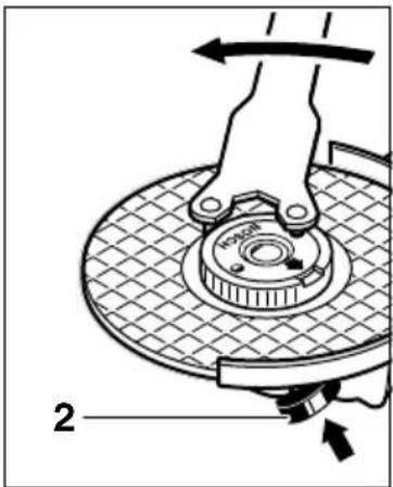
A properly closed and immovable latch can be released by turning the ring counterclockwise. Never use a screwdriver to loosen the installed latch.
Use only the key shown in the figure.
Permissible impact wrenches
All impact tools specified in the operating instructions can be used.
The permissible torque [Nm] or impact rate [1/min] used for the tool must correspond to the values given in the table.
Therefore, check the permissible torque or impact rate indicated on the tool before use.
| MaKC. [MM] | [ | MM] d -1XB. [ M/C] | |||
| D | b | ||||
| b D | 180 | 8 | 22,2 | 8 500 | 80 |
| 230 | 8 | 22,2 | 6 500 | 80 | |
| D | 180 | - | - | 8 500 | 80 |
| 230 | - | - | 6 500 | 80 | |
| b D | 100 | 30 M 1 | 4 8 500 | 45 | |
Starting work
Pay attention to the mains voltage: The power source voltage must match the value indicated on the tool's rating plate. A tool designed for 230 V can operate at 220 V.
Switching on and off
To switch on the tool, slide the switch forward and then press it.
For locking, push the switch forward while pressed and then release it.
To switch off the tool, release the switch or press and release it.
Switching on without locking (depending on tool version):
To switch on the tool, slide the switch forward and then press it.

Check operation!
Check the tool before work. The accessory must be correctly installed and turn freely. Perform a test run for 30 seconds without load. Do not use damaged, cracked or vibrating accessories.

Start-up current limiting (Type J)
As a result of a soft start, the current does not exceed 16 amps.

Tools without start-up current limiting require more protection (minimum fuse 16 A).
Work instructions
Clamp the workpiece if it can shift. Do not overload the tool. Grinding and cutting discs become very hot during work; do not touch them until they have cooled completely.
Grinding with flap discs
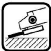
Work productivity is best when the angle between the flap disc and the surface is 30°-40°. Move the tool back and forth, applying moderate pressure. Then the workpiece will not become too hot, will not change color, and will not have grooves.

Never use cutting discs instead of grinding discs.
Work with backing pads (soft backing pads)
With the help of flexible backing pads (accessories), you can grind convex surfaces and profiles (contour grinding).
Flexible backing pads have significantly greater flexibility, their grinding strips are softer, lower noise level and lower grinding temperature.
Cutting discs
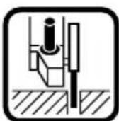
It is not necessary to press, press or push the device. It should be pushed with moderate speed so that it corresponds to the material being processed.
Do not press the diamond cutting disc with excessive force.
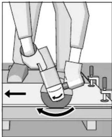
Important direction in which cutting is carried out.
Switch off the tool and, after it has completely stopped, place it on the machined surface.
Push the device with moderate speed so that it corresponds to the material being processed (see figure).
For particularly hard materials, such as concrete with a high gravel content, the diamond cutting disc may overheat and become stressed. This is indicated by a ring of sparks flying together with the diamond cutting disc.
In this case, stop the cutting process and allow the diamond cutting disc to cool down, running it briefly at no-load speed without pressure.
A noticeable decrease in work productivity and the appearance of a ring of sparks flying together are evidence that the diamond cutting disc has become dull. It can be sharpened again by making a few cuts in an abrasive material (e.g., sandstone).
Turning the tool head
Before any maintenance, pull the plug out of the socket.
The machine gearbox can be repositioned relative to the machine housing in 90-degree increments. Thus, the switch can be installed in a convenient position for specific working conditions, for example,
Cut out with the cutting guard 25, the cutting blade 28 (accessory) or the spacer. Unscrew all 4 screws.
Carefully turn the tool head to the new position, but without using force. Tighten and retighten the screws.
The instruction is printed on recycled paper and does not contain chlorine.
For sorting materials before recycling, each plastic part has the appropriate marking.
Senior Vice President Head of Product
Engineering Certification
Robert Bosch GmbH, Power Tools Division
Technical data
Bosch Service Center
Str. Horia Macelariu Nr. 30-34,
013937-Bucuresti
Tel. Power tools service: +40 (021) 4 05 75 40
Fax.: +40 (021) 4057566
E-Mail: infoBSC@ro.bosch.com
Tel. Technical consulting: +40 (021) 4 05 75 39
Fax.: +40 (021) 4057566
E-Mail: infoBSC@ro.bosch.com
www.bosch-romania.ro
C Declaration of Conformity
We declare under our sole responsibility that this product complies with the following standards and normative documents: EN 50 144 in accordance with the provisions of directives 89/336/EEC, 98/37/EC.
Dr. Egbert Schneider Dr. Eckerhard Strötgen
Senior Vice President Head of Product Engineering Certification
ppa.
Robert Bosch GmbH, Power Tools Division
Safety Instructions
Read all safety warnings and all instructions before using the power tool. Save all warnings and instructions for future reference.
Strictly follow the instructions given. It is also important to observe the general safety instructions in the attached brochure. Before first use of the machine, it is necessary to be trained by a specialist with practical experience in its use.
Work with protective goggles and ear protection (anti-noise or hearing protection). To increase safety, work also with other protective equipment, e.g. work gloves, safety shoes, helmet and work apron. Dust generated during work can be harmful to health, flammable or explosive. It is necessary to take appropriate protective measures. For example: dust from processing certain materials is carcinogenic. Use a dust extraction system and work with a breathing mask. Metal shavings generated during processing of light metals are flammable or explosive. Clean the work area regularly, because mixing dust from different metals is extremely dangerous. If during work the power cord is damaged or cut, do not touch the cord in any case. Immediately disconnect the plug from the mains. Never use the machine with a damaged power cord. Power tools used outdoors must be connected through a protective switch with a maximum trip current of 30 mA. Do not use the power tool in rain or high humidity. During work, hold the machine firmly with both hands. Work in a stable position. Secure the workpiece. When the workpiece is clamped in a vise or by another suitable method, it is held much more securely than when held by hand. Guide the power cord away from the machine.
Before using the power tool, read and follow the instructions for use. When switching on the tool, be careful not to accidentally start it. If the tool is switched on unintentionally, it may cause injury. Always keep the switch in the "Off" position when not in use. This will prevent uncontrolled starting of the power tool when the power supply is restored. The power tool is intended for dry sanding/dry grinding only. The auxiliary handle must be mounted when working with the machine. If the working tool becomes jammed with a hidden electrical wire or its own power cord, be careful to hold the power tool only by the insulated gripping surfaces. Contact with a live wire may make the exposed metal parts of the power tool live and could give the operator an electric shock. Use suitable detectors to locate hidden electric, gas, or water lines, or consult the responsible service. Contact with an electric wire can cause fire and/or electric shock. Damaging a gas line can lead to an explosion. Penetrating a water line causes property damage or may cause an electric shock. When working with sanding discs or grinding discs, the guard must be mounted. When working with the rubber sanding plate 20 or with the cup brush 23/disc brush/lamella disc, the guard 18 must be mounted (additional accessory). When processing stone materials, use a dust extraction system. The dust extractor must be certified for working with the respective materials. When grinding stone materials, use a water jet. Processing of asbestos-containing materials is not permitted. Use only tools for which the maximum permissible speed is at least equal to the no-load speed of the power tool.
Before starting work, check the tools. The tool must be mounted safely and must be able to rotate freely. Leave the tool to rotate in idle for at least 30 seconds without load. Do not use damaged tools or tools that cause strong vibrations. Protect the abrasive tools from impacts and shocks. Switch off the power tool before processing, after you have previously switched it on. Keep a safe distance from rotating parts. Align yourself with the direction of rotation of the abrasive tool. Hold the machine in such a way that sparks and chips produced during work are not directed towards you. When grinding metal, a large amount of sparks is produced. Be careful not to injure people nearby. Do not allow grinding in the vicinity (within the range of sparks) of flammable materials due to the risk of fire. Be careful when cutting channels in load-bearing walls: see the section on static stability. Blocking of the cutting disc leads to kickback. In such a situation, immediately switch off the power tool. Always use the correct dimensions of grinding tools. The opening of the grinding tool, resp. cutting disc must be precisely aligned with the centering flange. Do not use intermediate rings - adapters, bushings, etc. Never use cutting discs for rough grinding. Do not load the cutting discs with lateral pressure. When mounting and using abrasive tools, follow the manufacturer's instructions. Attention! After switching off the machine, the abrasive tool continues to rotate for some time due to inertia. Do not clamp the power tool in a vice. Under no circumstances allow children to work with the power tool. The company Bosch can guarantee the safe functioning of the power tool only if the original accessories are used.
Intended use of the power tool
The power tools are intended for cutting, rough grinding and brushing of metal and stone materials without the use of water. When cutting stone materials, the use of the water guide is mandatory.
Section on static stability
Cutting channels in load-bearing walls must be carried out in accordance with the requirements of standard DIN 1053, part 1 or the valid national normative documents.
Compliance with these normative documents is mandatory. Before starting work, consult with the responsible structural engineer, architect or the site management.

Mounting the protective devices
Before performing any work on the power tool, pull the plug out of the mains socket. When working with grinding or cutting discs, the protective guard must be mounted.
Protective guard with quick-release mechanism

The cutting head is pre-set for the diameter of the shaft. If necessary, the tension of the quick-clamping mechanism can be changed by loosening or tightening the adjusting screw 7. After the change, check that the cutting head is securely attached to the housing.
Release the lock 8.
Place the cutting head on the shaft, align it with the gear head, and tighten it to the lower position (working position).
To lock the cutting head, close the lock 8.
The locking side of the cutting head must always be turned away from the power tool.
Auxiliary handle
The auxiliary handle must be mounted when working with the machine.
Mount the auxiliary handle 4 on the side suitable for the work, on the head of the power tool.
Vibration-absorbing auxiliary handle
VIBRATION
CONTROL
The auxiliary handle, vibration-absorbing, provides a comfortable and safe work with the power tool.

Do not make any modifications to the auxiliary handle.
Do not work with a damaged auxiliary handle.
Protective screen
When working with grinding discs 20 N with a guard on the disc/grinding disc/plate disc, a protective device (additional attachment) must be installed. The protective guard 18 is secured with the auxiliary handle 4.
Mounting the grinding tools
Before performing any work on the power tool, disconnect the plug from the mains supply.

Use only grinding tools whose maximum permissible speed is at least equal to the maximum speed of the power tool. During operation, the grinding discs and cutting discs heat up considerably; do not touch them until they have cooled down.
Clean the shaft and all parts to be mounted. To loosen and tighten the clamping nut, lock the spindle 5 with the spanner 2.
Press the spindle lock button 2 only when the spindle is at a standstill!
Grinding disc
Observe the specified dimensions of the grinding tools. The bore of the grinding or cutting disc must fit precisely onto the centering flange 9. Do not use reducing rings or adapters.
Ventilated grinding disc
Depending on the specific conditions, the protective guard and the auxiliary handle 18 may need to be removed and remounted. Place the special flange (additional attachment) on the spindle 5 and the ventilated grinding disc (accessory, order no. 2 605 703 028). Tighten the clamping nut 11 and then tighten it with the special wrench.
Diamond cutting disc

When working with diamond cutting discs, use the special protective guard 15.
The diamond cutting disc 16 must protrude from the protective guard 15 only as much as is absolutely necessary for the specific work.
Adjust the protective guard 15 accordingly as you work.
For mounting, see the figure.
Tighten the nut with a 17 mm wrench.
Quick-release SDS-clip nut
Instead of the tightening nut 11, the quick-release nut 12 (optional accessory) can be used. With its help, the discs can be changed without using auxiliary tools.
The use of the special quick-release nut 12 is only permitted for tightening discs for cutting/grinding.
Use only quick-release nuts 12 in flawless condition.
When placing the nut, make sure that the side with the inscription is not facing the disc; the arrow must point to the marking 29.
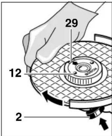
Lock the machine shaft (with the aid of the spanner 2) and then tighten the quick-release nut by firmly turning the disc in the direction of the clockwise arrow.
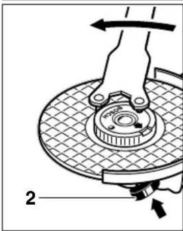
A correctly placed special quick-release nut can be released by turning the ring nut by hand counterclockwise and then clockwise.
In no case should you attempt to release the tightening nut quickly
Quick-release nut mounted; use the special two-pin wrench.
Place the wrench as shown in the figure.
Switching On/Off
To switch on the power tool, press the lock-off button 3 and then the on/off switch.
To lock the on/off switch 3 in the on position, press it again and then hold it down.
To switch off the power tool, release, respectively press and release the on/off switch.
Pressure on the trigger switch without the possibility of locking (special production for wear in some countries):
To switch on the power tool, press the trigger switch and keep it pressed.
To switch off the power tool, release the trigger switch.

Switching on! Before use, check the grinding tool. The tool must be mounted without defects and must be able to rotate freely. Before use, let it run for at least 30 seconds at no load. Do not use damaged, eccentric, or vibrating tools.

Trigger switch lock (Model J)
Locking the switch on When the power tool is switched on, it can be locked in the ON position by pressing the trigger switch further.

Power tool without trigger switch lock requires a residual current device (RCD) with a rated current of at least 16 A.
Working instructions
Clamp the workpiece if it does not remain stable under its own weight. Do not overload the power tool to the point where the motor stalls. During work, the grinding and cutting discs get very hot; do not touch them until they have cooled down.
Rough sanding
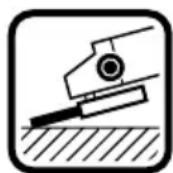
The best results in rough sanding are achieved when the tool is tilted at an angle of 30° to 40° to the workpiece surface. Apply moderate pressure and move the tool
back and forth over the surface. In this way, the tool will not overheat, the color will not change, and no deep grooves will form.

Never use cutting discs for rough sanding!
Flap disc for surface sanding
With the help of an abrasive disc for flat surfaces (additional accessory), curved surfaces and profiles can be processed.
Always use the disc for cutting only. When working with it, the noise level is lower and the temperature of the processed surface rises to a lesser degree.
Cutting
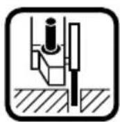
When cutting, do not press hard, do not tilt the disc, do not use lateral force. Work evenly, in proportion to the feed of the part being processed.
Do not force the disc's rotation by tilting the machine or pressing from both sides.
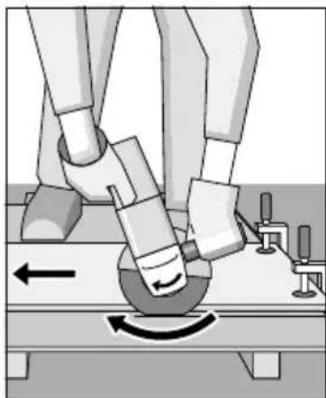
The guide is especially important for making the cut.
With the power tool, you must work in the direction of the cutting motion; therefore, do not push it in the opposite direction! Otherwise, there is a
danger of the cutting disc being thrown out of control due to the cutting force.
Cutting stand
With the cutting stand 28 (accessory), parts with equal height can be cut precisely at an angle from 0° to 45°.
It is essential to strictly follow the safety conditions and instructions for working with the cutting stand, given in the operating manual for the stand. Use only original stands manufactured by the company.
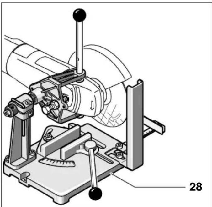
Cutting ceramic materials
The power tool may be used only for dry grinding/dry cutting.
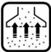

It is best to use a diamond cutting disc. For safety, the guard 25 must be closed; it is best to use the special dust extraction hood.
Work with the power tool only when using the dust extraction system. In addition, wear a suitable dust mask.
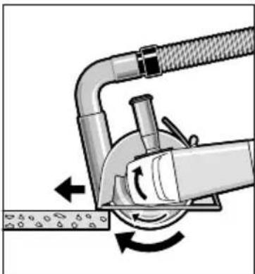
The extraction unit must be suitable for stone dust.
The machine is designed for cutting metal.
Switch on the machine and place the tool on the workpiece.
Operate the power tool moderately, according to the processing of the parts being cut (see figure).
When cutting abrasive materials, e.g. concrete with a high content of quartz, the diamond cutting disc may overheat and be damaged. An indication of overheating is the formation of sparks and a ring around its periphery.
In such a case, stop work and let the diamond disc cool down, leaving it to run idle for some time.
The deliberately reduced cutting speed and the formation of sparks around the disc are an indication of blunting of the diamond disc. This can be remedied by briefly cutting into an abrasive material (e.g. brick).
Adjusting the gearbox housing
Before carrying out any work on the power tool, pull the plug out of the socket.
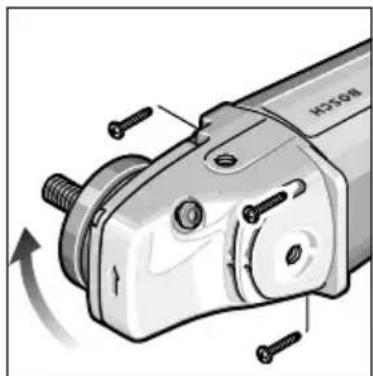
The gearbox head can be turned relative to the housing in steps of up to 90°. In this way, under special working conditions, the trigger switch can be placed in a more convenient position; e.g. when cutting with a guide rail 25/
When working with the cutting guide 28 (accessory) or if you prefer to work with both hands.
Unscrew all four screws.
Turn the gearbox head to the new position WITHOUT removing it from the housing.
Tighten the screws again.
Adjusting the auxiliary handle (GWS 24/26-180/230 (J)B)
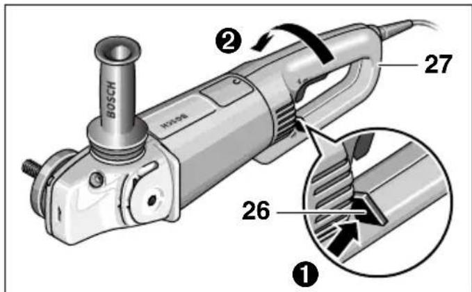
The auxiliary handle 27 can be turned relative to the housing of the power tool in steps of up to 90°. Thus, if necessary, e.g. if you work with both hands or when using the guide rail/cutting guide (accessory), the trigger switch can be placed in a more convenient working position.
Turn the release button 26 clockwise in the direction indicated by the arrow (1) and simultaneously turn the handle 27 to the desired position (2),
until the locking mechanism engages clearly. The handle 27 is shown turned 90 degrees.

The release button 26 and the trigger switch 3 are mutually interlocked.
The power tool can only be switched on when the handle 27 is in one of the three possible positions.
The handle 27 cannot be released and turned while the trigger switch 3 is activated.
The noise level measured from the power tool is typically: sound pressure level 90 dB (A); sound power level 103 dB (A).
Wear hearing protection (ear muffs or ear plugs)!
The vibration acceleration is typically 5.5 m/s².
When using the auxiliary handle, the vibrations transmitted to the hand are typically lower than 2.5 m/s².
Service and consultation
The service department will answer your questions regarding repairs and maintenance of your purchased product, as well as regarding spare parts.
Assembly drawings and information on spare parts can also be found at
www.bosch-pt.com
The Bosch experts will be happy to assist you with questions regarding purchasing, application, and adjustment options for the various products from the Bosch range and their accessories.
Robert Bosch EOOD - Bulgaria
Translation from Bulgarian: 'IMPORTANT INSTRUCTIONS FOR IMPORTANT REPAIRS'
Translation from Bulgarian: 'st. Srebarna No. 9'
1907 Sofia
Tel.: +359 (02) 962 5302
Tel.: +359 (02) 962 5427
Tel.: +359 (02) 962 5295
Fax: +359 (02) 624649
Translation from Bulgarian: 'Declaration of Conformity'
Translation from Bulgarian: 'We declare under our sole responsibility that this product complies with the following standards and normative documents: EN 50 144, as well as with the requirements of the following directives: 89/336/EWG, 98/37/EG.'
Dr. Egbert Schneider Dr. Eckerhard Strotgen Senior Vice President Head of Product Engineering Certification
Robert Bosch GmbH, Power Tools Division
Translation from Bulgarian: 'Rights to changes reserved'
| Ugaona brusilica | GWS 21-180 H Professional | GWS 21-230 H Professional | GWS 24-180 B Professional |
| Broj narudžbine 0 601 851 0.. 0 601 852 0.. 0 601 853 0.. | |||
| Sa ogranicavanjem struje kretanja | GWS 21-180 JH Professional | GWS 21-230 JH Professional | GWS 24-180 JB Professional |
| Broj narudžbine 0 601 851 9.. 0 601 852 9.. 0 601 853 9.. | |||
| Nominalni prijem snage* | [W] 2 100 2 100 2 400 | ||
| Predana snaga [W] 1 350 1 350 1 700 | |||
| Broj obrtaja na prazno | [miñ-1] 8 500 6 500 8 500 | ||
| Brusne ploche, maks. | [mm] 180 230 180 | ||
| Navoj brusnog vretena | M 14 M 14 M 14 | ||
| Težina bez mrežnog kabla, ca. | [kg] 4,3 4,3 5,1 | ||
| Klasa zašite / II / II / II | ☑ | ☑ | ☑ |
| Ugaona brusilica | GWS 24-180 H Professional | GWS 24-230 B Professional | GWS 24-230 H Professional |
| Broj narudžbine 0 601 853 4.. 0 601 854 0.. 0 601 854 4.. | |||
| Sa ogranicavanjem struje kretanja | GWS 24-230 JB Professional | GWS 24-230 JH Professional | |
| Broj narudžbine 0 601 854 9.. 0 601 854 5.. | |||
| Nominalni prijem snage* | [W] 2 400 2 400 2 400 | ||
| Predana snaga [W] 1 700 1 700 1 700 | |||
| Broj obrtaja na prazno | [miñ-1] 8 500 6 500 6 500 | ||
| Brusne ploche, maks. | [mm] 180 230 230 | ||
| Navoj brusnog vretena | M 14 M 14 M 14 | ||
| Težina bez mrežnog kabla, ca. | [kg] 5,1 5,1 5,1 | ||
| Klasa zašite / II / II / II | ☑ | ☑ | ☑ |
| Ugaona brusilica | GWS 26-180 B Professional | GWS 26-180 H Professional | GWS 26-230 B Professional | GWS 26-230 H Professional |
| Broj narudžbine 0 601 855 0.. 0 601 855 4.. 0 601 856 0.. 0 601 856 4.. | ||||
| Sa ogranicavanjem struje kretanja | GWS 26-180 JB Professional | GWS 26-230 JB Professional | GWS 26-230 JH Professional | |
| Broj narudžbine 0 601 855 9.. 0 601 856 9.. 0 601 856 5.. | ||||
| Nominalni prijem snage* | [W] 2 600 2 600 2 600 2 600 | |||
| Predana snaga [W] 1 800 1 800 1 800 1 800 | ||||
| Broj obrtaja na prazno | [miñ-1] 8 500 8 500 6 500 6 500 | |||
| Brusne ploche, maks. | [mm] 180 180 230 230 | |||
| Navoj brusnog vretena | M 14 M 14 M 14 M 14 | |||
| Težina bez mrežnog kabla, ca. | [kg] 5,1 | 5,1 | 5,1 | 5,1 |
| Klasa zašite | ☐ / II | ☐ / II | ☐ / II | |
- Data applies to nominal voltages [U] 230/240 V. For lower voltages and in country-specific versions, these data may vary. Pay attention to the order number of your machine. Trade names of individual machines may vary. Switching operations cause brief voltage drops. Under unfavorable mains conditions, damage to other devices may occur. With mains impedances less than 0.25 ohm, malfunctions can be expected.
Part K with image
The numbering of the device components refers to the device illustration on the graphic page.
Please open the fold-out page with the machine illustration and follow the illustration on this page while reading the operating instructions.
1 Thread of auxiliary handle (3x) 2 Spindle lock button 3 On/off switch 4 Auxiliary handle 5 Grinding spindle 6 Protective cover 7 Calibration screw 8 Tension lever 9 Connection flange with O-ring 10 Coarse grinding/cutting disc 11 Tension nut 12 Quick-clamping nut *SDS-clic 13 Clamping screw 14 Coding outlet 15 Protective cover for grinding cup 16 Grinding cup
17 Wrench for tension nut 18 Hand guard 19 Spacer plate 20 Rubber sanding pad 21 Sanding sheet 22 Round nut 23 Brush 24 Diamond cutting disc 25 Slide guide with suction hood 26 Handle release 27 Handle 28 Cutting stand with grinding disc
- Accessories shown or described are not always included in the delivery scope.

For your safety
Work with the device is only possible without danger if you completely read the operating instructions and safety instructions and then strictly follow the advice given in
them. Additionally, you must follow the general safety instructions in the enclosed booklet. Before first use, let these instructions "introduce" you practically to the work.
■Wear protective goggles and hearing protection. ■For safety, also wear other protective equipment such as protective gloves, sturdy shoes, helmet, and apron. ■Dust generated during work can be harmful to health, flammable, or explosive. Appropriate protective measures are necessary. For example: Some dusts are carcinogenic. Use appropriate dust/chip extraction and wear a protective mask. ■Dust from light metals can burn or explode. Always keep the work area clean, as material mixtures are particularly dangerous. ■If the mains cable is damaged or cut during work, do not touch the cable but immediately pull the plug out of the mains. Never use the device with a damaged cable. Devices used outdoors must be connected via a residual current device (RCD) with a maximum tripping current of 30 mA. Do not use the device in rain or moisture. ■During work, always hold the device firmly with both hands and ensure you stand stably. Secure the workpiece. A workpiece held by clamping devices or a vise is safer than holding it by hand. Always route cables to the rear of the device. Always switch off the device before putting it down and wait until it stops. ■In case of power failure or when unplugging the mains plug, immediately release the lock of the on/off switch and set it to the off position. This will prevent uncontrolled restarting. The device may only be used for dry grinding/dry cutting. ■When working with the device, the auxiliary handle must be mounted.
■ Hold power tools only by the insulated gripping surfaces, because the tool may come into contact with hidden wiring or its own power cord. Contact with a live wire can energize the metal parts of the tool and lead to an electric shock. ■ Use suitable detectors to find hidden supply lines or call the local utility company. Contact with electric lines can cause fire and electric shock. Damage to a gas line can lead to an explosion. Penetrating a water line causes property damage or can cause an electric shock. For work with grinding or cutting discs, the protective guard 6 must be mounted. For work with a rubber sanding plate 20, or with a cup brush 23/disc brush/ flap disc, the hand guard 18 (accessory) must be mounted. ■ When working on stone, use a dust extraction system. The dust extraction system must be approved for vacuuming stone dust. For cutting stone, use a guide rail. ■ Material containing asbestos must not be processed. ■ Use only grinding tools whose permissible speed is at least as high as the no-load speed of the tool. ■ Check grinding tools before use. The grinding tool must be properly mounted and turn freely. Perform a test run for at least 30 seconds without load. Do not use damaged, out-of-round, or vibrating grinding tools. Protect grinding tools from impacts, shocks, and grease. Only bring the tool into contact with the workpiece when it is switched on. ■ Keep hands away from rotating grinding tools. ■ Pay attention to the direction of rotation. Always hold the tool so that sparks and dust fly away from your body. ■ When grinding metal, sparks are produced. Ensure that no one is endangered by them. Due to the risk of fire, no flammable materials should be nearby (at least in the area where sparks fly). ■ Be careful when cutting slots, e.g., in load-bearing walls: See the instructions on statics.
■ In case of a power failure or if the mains plug is pulled out, immediately release the on/off switch and set it to the OFF position. This prevents uncontrolled restarting. Pay attention to the dimensions of the grinding discs. The bore of the grinding/cutting disc must fit without play on the mounting flange 9. Do not use any reducing pieces or adapters. Never use a cutting disc for rough grinding. Never subject a cutting disc to lateral pressure. Follow the manufacturer's instructions when mounting and using the grinding tool. ■ Caution: The grinding tool continues to run for a few seconds after the tool is switched off. Never clamp the tool in a vise. ■ Never allow children to use the tool. ■ Bosch can only guarantee proper functioning of the tool if original accessories are used.
Intended use
The device is intended for cutting, roughing, and brushing metal and stone materials without the use of water. For cutting stone, a sliding guide is prescribed.
Instructions for static stability
Cutouts in load-bearing walls are subject to standard 1053 part 1 or regulations specific to the country.
These regulations must be strictly observed. Before starting work, consult the responsible structural engineer, architect, or appropriate construction supervisors.

Dr. Egbert Schneider Dr. Eckerhard Strötgen Senior Vice President Head of Product Engineering Certification

Robert Bosch GmbH, Power Tools Division
Senior Vice President Head of Product Engineering Certification
ppa.
Robert Bosch GmbH, Power Tools Division
We reserve the right to make changes.
Technical data
| Kutna brusilica GWS 21-180 H Professional | GWS 21-230 H Professional | GWS 24-180 B Professional | |||
| Kataloški broj 0 601 851 0.. 0 601 852 0.. 0 | 601 853 0.. | ||||
| S ograničenjem struje zaleta | GWS 21-180 JH Professional | GWS 21-230 JH Professional | GWS 24-180 JB Professional | ||
| Kataloški broj 0 601 851 9.. 0 601 852 9.. 0 | 601 853 9.. | ||||
| Nazivna primljena snaga* | [W] 2 100 2 100 2 400 | ||||
| Predana snaga [W] 1 350 1 350 1 700 | |||||
| Broj okretaja pri praznom hodu | [min-1] 8 500 6 500 8 500 | ||||
| Ø brusne ploche, max. | [mm] 180 230 180 | ||||
| Navoj brusnog vretena | M 14 M 14 M 14 | ||||
| Težina mrežnog kabela, cca. | [kg] 4,3 4,3 5,1 | ||||
| Klasa zašite / II / II / II | □ | □ | □ | ||
| Kutna brusilica GWS 24-180 H Professional | GWS 24-230 B Professional | GWS 24-230 H Professional |
| Kataloški broj 0 601 853 4.. 0 601 854 0.. 0 | 601 854 4.. | |
| S ograničenjem struje zaleta | GWS 24-230 JB Professional | GWS 24-230 JH Professional |
| Kataloški broj | 0 601 854 9.. 0 | 601 854 5.. |
| Nazivna primljena snaga* [W] 2 400 2 400 2 400 | ||
| Predana snaga [W] 1 700 1 700 1 700 | ||
| Broj okretaja pri praznom hodu [min-1] 8 500 6 500 6 500 | ||
| Ø brusne ploche, max. [mm] 180 230 230 | ||
| Navoj brusnog vretena M 14 M 14 M 14 | ||
| Težina mrežnog kabela, cca. [kg] 5,1 5,1 5,1 | ||
| Klasa zašite / II / II / II | [□] | [□] |
| Kutna brusilica GWS 26-180 B struje zaleta | Professional | GWS 26-180 H Professional | GWS 26-230 B Professional | GWS 26-230 H Professional |
| Kataloški broj 0 601 855 0.. 0 601 855 4.. 0 601 856 0.. 0 601 856 4.. | ||||
| S ograničenjem struje strueta | GWS 26-180 JB Professional | GWS 26-230 JB Professional | GWS 26-230 JH Professional | |
| Kataloški broj 0 601 855 9.. 0 601 856 9.. 0 601 856 5.. | ||||
| Nazivna primljena snaga* | [W] 2 600 2 600 2 600 2 600 | |||
| Predana snaga [W] 1 800 1 800 1 800 1 800 | ||||
| Broj okretaja pri praznom hodu | [min-1] 8 500 8 500 6 500 6 500 | |||
| Ø brusne ploche, max. | [mm] 180 | 180 | 230 | 230 |
| Navoj brusnog vretena | M 14 | M 14 | M 14 | |
| Težina mrežnog kabela, cca. | [kg] 5,1 | 5,1 | 5,1 | 5,1 |
| Klasa zašite | ☐ / II | ☐ / II | ☐ / II | |
Dr. Egbert Schneider Dr. Eckerhard Strötgen Senior Vice President Head of Product Engineering Certification
i.v. Noto
Robert Bosch GmbH, Power Tools Division
Dr. Egbert Schneider Dr. Eckerhard Strötgen Senior Vice President Head of Product Engineering Certification
Robert Bosch GmbH, Power Tools Division
Dr. Egbert Schneider Dr. Eckerhard Strötgen Senior Vice President Head of Product Engineering Certification

Robert Bosch GmbH, Power Tools Division
Subject to change without notice
POSSIBILITIES
Dr. Egbert Schneider Dr. Eckerhard Strötgen Senior Vice President Head of Product Engineering Certification
Robert Bosch GmbH, Power Tools Division
Subject to change without notice
BOSCH
Ideas that work.
Power Tools Division
70745 Leinfelden-Echterdingen
www.bosch-pt.com
1609929R35(03.11)O/262
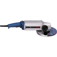

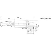
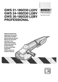
- GWS 21-180/230 (J)H GWS 24-180/230 (J)B GWS 24-180/230 (J)H GWS 26-180/230 (J)B GWS 26-180/230 (J)H PROFESSIONAL
- MACHINE ELEMENTS FOR YOUR SAFETY
- INTENDED USE
- INFORMATION ON STRUCTURES
- MOUNTING THE PROTECTIVE DEVICES
- PROTECTION GUARD WITH LOCKING SCREW
- PROTECTION GUARD WITH QUICK CLAMP
- AUXILIARY HANDLE
- VIBRATION-DAMPENING AUXILIARY HANDLE
- VIBRATION CONTROL
- HAND GUARD
- MOUNTING THE GRINDING TOOLS
- GRINDING/CUTTING DISC
- FLAP DISC
- RUBBER SANDING PLATE
- CUP BRUSH 23/DISC BRUSH
- GRINDING CUP
- QUICK CLAMPING NUT SDS-E/IE
- APPROVED GRINDING TOOLS
- INITIAL OPERATION
- SWITCHING ON AND OFF
- SWITCH VERSION WITHOUT LOCK (COUNTRY-SPECIFIC)
- TEST RUN
- REDUCED STARTING CURRENT (TYPE J)
- OPERATING INSTRUCTIONS
- ROUGH GRINDING
- CUTTING
- GRINDER STAND
- CUTTING STONE
- ROTATING THE MACHINE HEAD
- BEFORE ANY WORK ON THE MACHINE ITSELF, PULL THE MAINS PLUG
- TURNING THE MACHINE HANDLE (GWS 24/26-180/230 (J)B)
- MAINTENANCE AND CLEANING
- WARNING! IMPORTANT INSTRUCTIONS FOR CONNECTING A NEW 3-PIN PLUG TO THE 2-WIRE CABLE
- ENVIRONMENTAL PROTECTION
- RECYCLE RAW MATERIALS INSTEAD OF DISPOSING AS WASTE
- NOISE/VIBRATION INFORMATION
- WEAR HEARING PROTECTION
- AFTER-SALES SERVICE AND CUSTOMER ASSISTANCE
- WWW.BOSCH-PT.COM
- GREAT BRITAIN
- AUSTRALIA, NEW ZEALAND AND PACIFIC ISLANDS
- DECLARATION OF CONFORMITY
- TECHNICAL SPECIFICATIONS
- MOUNTING ABRASIVE TOOLS
- SNELSPANMOER SDS-ELIC
- OVERENSSTEMMELSES-ERKLARING
- C DECLARATION OF CONFORMITY
- TECHNICAL DATA
- ILLUSTRATED COMPONENT PARTS
- FOR YOUR SAFETY
- INFORMATION ON STATICS
- PROTECTIVE GUARD WITH CLAMPING SCREW
- PROTECTIVE GUARD WITH QUICK-RELEASE FASTENER
- ADDITIONAL HANDLE
- ADDITIONAL HANDLE WITH VIBRATION DAMPING
- VIBRATION
- CONTROL
- DEVICE FOR HAND PROTECTION
- INSTALLING THE GRINDING TOOL
- ROUGH GRINDING (GRINDING) DISC / CUTTING DISC
- ASSEMBLY: SEE PAGE WITH FIGURE
- GRINDING DISC WITH HOLES (SEGMENTED GRINDING DISC)
- RUBBER SANDING DISC
- WASHER 23/DISC
- STARTING CURRENT LIMITING (FOR J)
- APPLICATION INSTRUCTIONS
- ROUGHING (FLAP) DISC
- FIBER DISCS ("FLAP" GRINDING DISCS)
- CUTTING WITH A GRINDING DISC
- STATIONARY CUTTING/GRINDING MACHINE WITH DIAMOND CUTTING WHEEL
- BEFORE STARTING MAINTENANCE WORK ON THE POWER TOOL, DISCONNECT THE MAINS PLUG FROM THE SOCKET
- DISPOSAL
- RECYCLING OF RAW MATERIALS INSTEAD OF WASTE DISPOSAL
- BELARUS
- LIMITED LIABILITY COMPANY
- COMPONENTS SHOWN
- ACCESSORIES FOR THE TOOL
- SAFETY INSTRUCTIONS REGARDING BUILDING STRUCTURES
- MOUNTING THE SAFETY DEVICES
- GUARD WITH LOCKING SCREW
- GUARD WITH QUICK-RELEASE SYSTEM
- DO NOT USE IT AS AN ADDITIONAL HANDLE
- HAND PROTECTION
- MOUNTING THE GRINDING TOOL
- GENERAL-PURPOSE / SPECIAL-PURPOSE CIRCLES
- MOUNTING - SEE FIGURE
- BIOLOGICAL TABLET (SOFT TABLET)
- BLIND FLANGE
- WRENCH SIZE 23 / SOCKET SIZE
- RATCHET WRENCH
- ASSEMBLY - SEE FIGURE
- QUICK-RELEASE NUT SDS-CLIC
- QUICK-RELEASE NUT 12 IS USED ONLY FOR TIGHTENING AND LOOSENING CIRCLES
- USE ONLY AN UNDAMAGED QUICK-RELEASE NUT
- PERMISSIBLE IMPACT WRENCHES
- STARTING WORK
- SWITCHING ON WITHOUT LOCKING (DEPENDING ON TOOL VERSION)
- CHECK OPERATION
- START-UP CURRENT LIMITING (TYPE J)
- WORK INSTRUCTIONS
- GRINDING WITH FLAP DISCS
- WORK WITH BACKING PADS (SOFT BACKING PADS)
- CUTTING DISCS
- TURNING THE TOOL HEAD
- BEFORE ANY MAINTENANCE, PULL THE PLUG OUT OF THE SOCKET
- SAFETY INSTRUCTIONS
- INTENDED USE OF THE POWER TOOL
- SECTION ON STATIC STABILITY
- PROTECTIVE GUARD WITH QUICK-RELEASE MECHANISM
- VIBRATION-ABSORBING AUXILIARY HANDLE
- PROTECTIVE SCREEN
- GRINDING DISC
- VENTILATED GRINDING DISC
- DIAMOND CUTTING DISC
- FOR MOUNTING, SEE THE FIGURE
- QUICK-RELEASE SDS-CLIP NUT
- SWITCHING ON/OFF
- TRIGGER SWITCH LOCK (MODEL J)
- WORKING INSTRUCTIONS
- ROUGH SANDING
- NEVER USE CUTTING DISCS FOR ROUGH SANDING
- FLAP DISC FOR SURFACE SANDING
- CUTTING STAND
- CUTTING CERAMIC MATERIALS
- ADJUSTING THE GEARBOX HOUSING
- ADJUSTING THE AUXILIARY HANDLE (GWS 24/26-180/230 (J)B)
- WEAR HEARING PROTECTION (EAR MUFFS OR EAR PLUGS)
- SERVICE AND CONSULTATION
- ROBERT BOSCH EOOD - BULGARIA
- TRANSLATION FROM BULGARIAN: 'DECLARATION OF CONFORMITY
- PART K WITH IMAGE
- INSTRUCTIONS FOR STATIC STABILITY
- POSSIBILITIES
- BOSCH
Brand : BOSCH
Model : GWS 21230 JHV Professional
Category : Angle grinder