
HWS 88230 Professional - Angle grinder BOSCH - Free user manual and instructions
Find the device manual for free HWS 88230 Professional BOSCH in PDF.
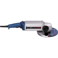


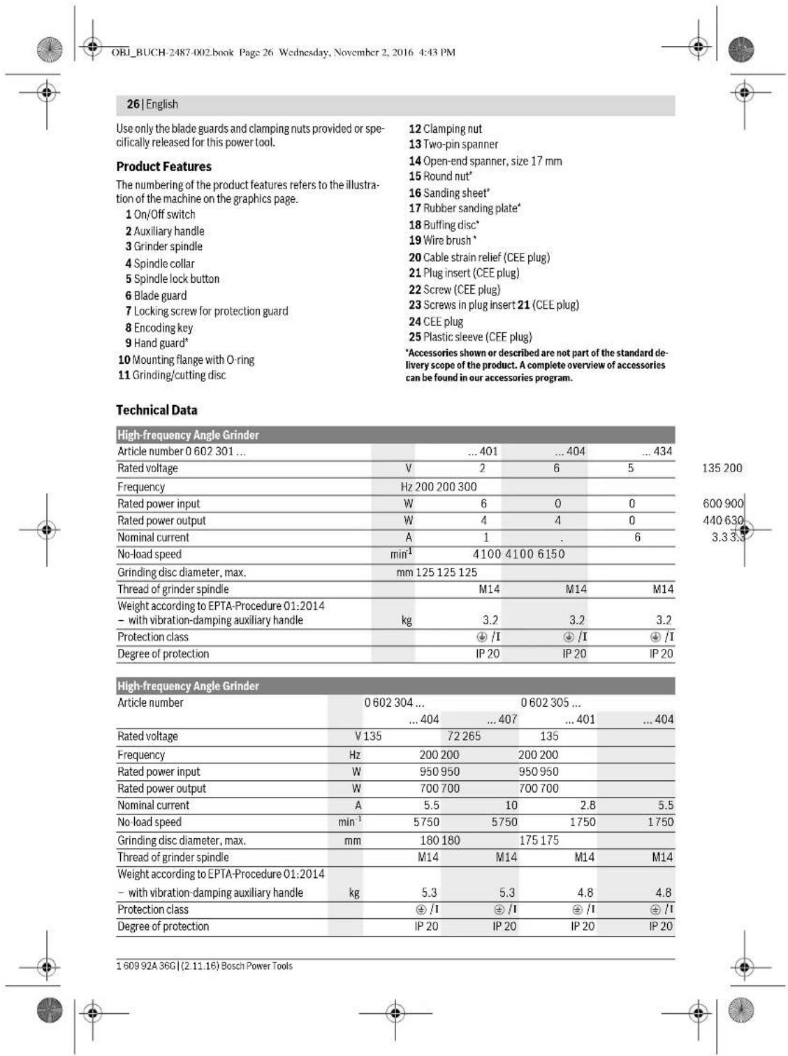
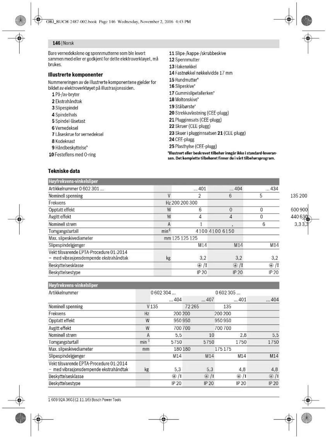
| Product Type | Angle Grinder |
| Brand | Bosch |
| Model | HWS 88230 Professional |
| Category | High-frequency power tool |
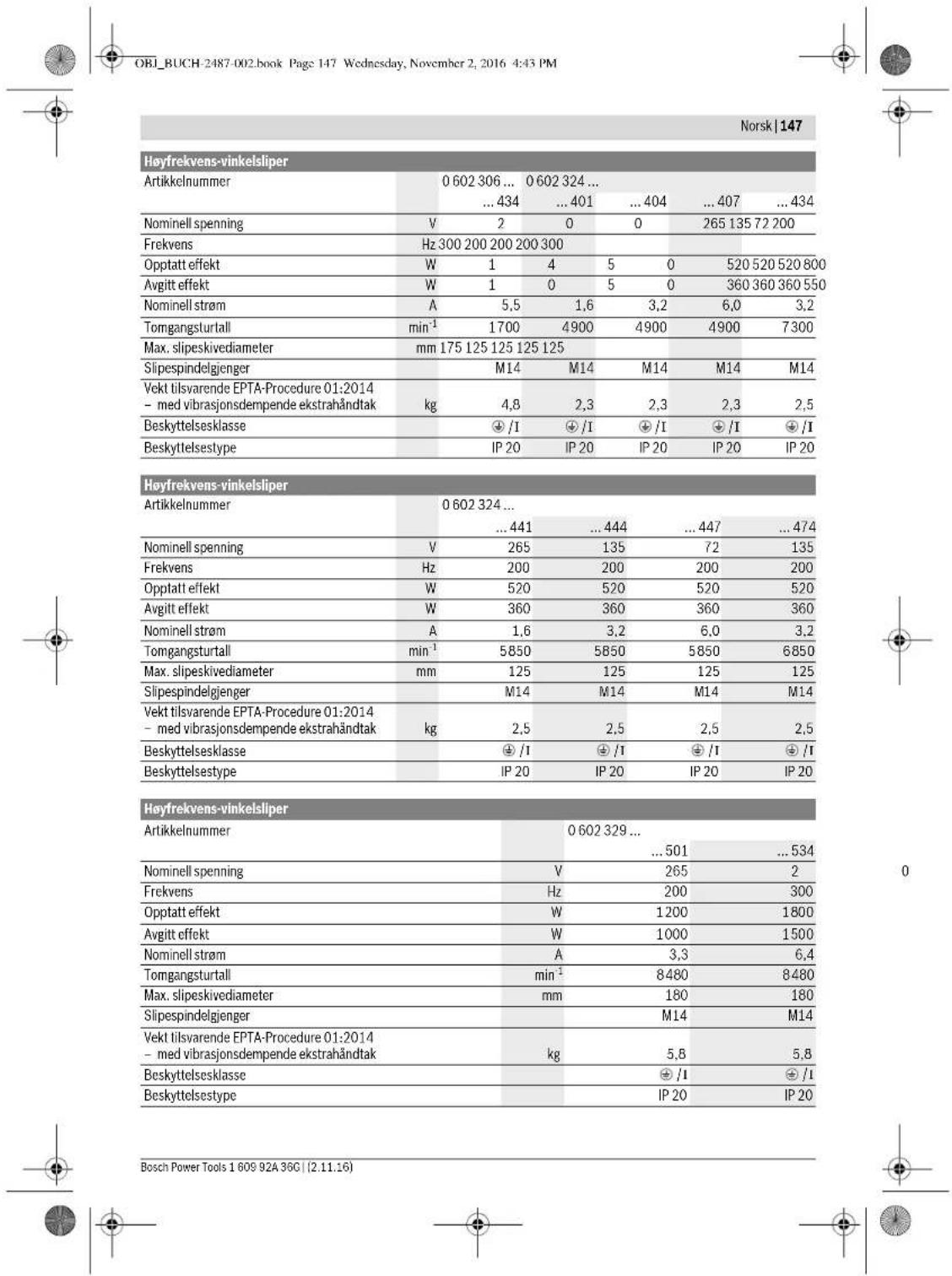
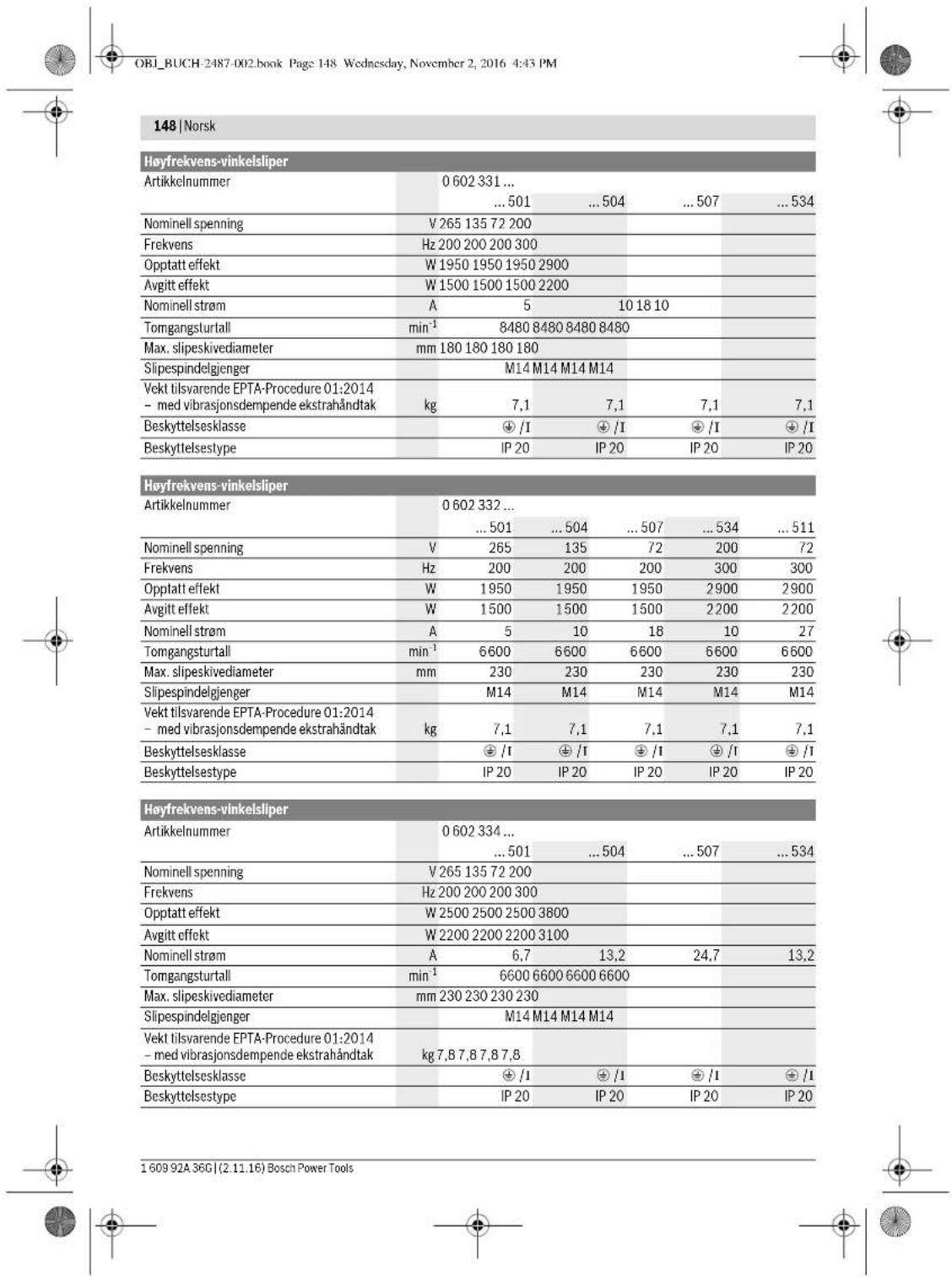
| Max disc diameter | 125 mm |
| Rated power | 950 W |
| Rated frequency | 200 Hz |
| Rated voltage | 200 V (three-phase) |
| No-load speed | 9500 min⁻¹ (depending on model) |
| Spindle thread | M14 |
| Weight (according to EPTA standard) | approx. 2.8 kg |
| Auxiliary handle | Vibration-dampening |
| Hand guard | Included for work with sanding plate or brush |
| Protection guard | For grinding and cutting (adapted according to use) |
| Switch | Sliding or Tricontrol with locking |
| Required power supply | Frequency converter for high-frequency three-phase current |
| Applications | Grinding, cutting, sanding, brushing of metal and stone (dry) |
| Maintenance | Clean ventilation slots regularly; check no-load speed |
| Included accessories | Fork wrench, hand guard, auxiliary handle |
| Repairability | Spare parts available; Bosch after-sales service |
Frequently Asked Questions - HWS 88230 Professional BOSCH
User questions about HWS 88230 Professional BOSCH
0 question about this device. Answer the ones you know or ask your own.
Ask a new question about this device
Download the instructions for your Angle grinder in PDF format for free! Find your manual HWS 88230 Professional - BOSCH and take your electronic device back in hand. On this page are published all the documents necessary for the use of your device. HWS 88230 Professional by BOSCH.
USER MANUAL HWS 88230 Professional BOSCH
Robert Bosch Power Tools GmbH
70538 Stuttgart
GERMANY
www.bosch-pt.com
160992A36G(2015.07)AS/473 EURO
1609 92A 36G
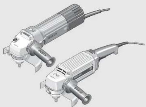
HWS
06023014..|060230440.060230540.0602306434|06023244..
06023295..|06023315..|06023325..|06023345..

BOSCH
16 | English
Executive Vice President
Head of Product Certification
Engineering
PT/ECS
f(2) = h · d
Robert Bosch Power Tools GmbH
70538 Stuttgart, GERMANY
Stuttgart, 01.01.2017
Assembly
General Power Tool Safety Warnings
WARNING Read all safety warnings and all instructions. Failure to follow the warnings and instructions may result in electric shock, fire and/or serious injury.
Save all warnings and instructions for future reference. The term "power tool" in the warnings refers to your mains-operated (corded) power tool or battery-operated (cordless) power tool.
Work area safety
- Keep work area clean and well lit. Cluttered or dark areas invite accidents. Do not operate power tools in explosive atmospheres, such as in the presence of flammable liquids, gases or dust. Power tools create sparks which may ignite the dust or fumes.
- Keep children and bystanders away while operating a power tool. Distractions can cause you to lose control.
Electrical safety
Power tool plugs must match the outlet. Never modify the plug in any way. Do not use any adapter plugs with earthed (grounded) power tools. Unmodified plugs and matching outlets will reduce risk of electric shock. - Avoid body contact with earthed or grounded surfaces, such as pipes, radiators, ranges and refrigerators. There is an increased risk of electric shock if your body is earthed or grounded. Do not expose power tools to rain or wet conditions. Water entering a power tool will increase the risk of electric shock. Do not abuse the cord. Never use the cord for carrying, pulling or unplugging the power tool. Keep cord away from heat, oil, sharp edges and moving parts. Damaged or entangled cords increase the risk of electric shock. - When operating a power tool outdoors, use an extension cord suitable for outdoor use. Use of a cord suitable for outdoor use reduces the risk of electric shock.
If operating a power tool in a damp location is unavoidable, use a residual current device (RCD) protected supply. Use of an RCD reduces the risk of electric shock.
Personal safety
Stay alert, watch what you are doing and use common sense when operating a power tool. Do not use a power tool while you are tired or under the influence of drugs, alcohol or medication. A moment of inattention while operating power tools may result in serious personal injury. Use personal protective equipment. Always wear eye protection. Protective equipment such as dust mask, non-skid safety shoes, hard hat, or hearing protection used for appropriate conditions will reduce personal injuries. Prevent unintentional starting. Ensure the switch is in the off-position before connecting to power source and/or battery pack, picking up or carrying the tool. Carrying power tools with your finger on the switch or energising power tools that have the switch on invites accidents. Remove any adjusting key or wrench before turning the power tool on. A wrench or a key left attached to a rotating part of the power tool may result in personal injury. Do not overreach. Keep proper footing and balance at all times. This enables better control of the power tool in unexpected situations. Dress properly. Do not wear loose clothing or jewellery. Keep your hair, clothing and gloves away from moving parts. Loose clothes, jewellery or long hair can be caught in moving parts. If devices are provided for the connection of dust extraction and collection facilities, ensure these are connected and properly used. Use of dust collection can reduce dust-related hazards.
Power tool use and care
Do not force the power tool. Use the correct power tool for your application. The correct power tool will do the job better and safer at the rate for which it was designed. Do not use the power tool if the switch does not turn it on and off. Any power tool that cannot be controlled with the switch is dangerous and must be repaired. Disconnect the plug from the power source and/or the battery pack from the power tool before making any adjustments, changing accessories, or storing power tools. Such preventive safety measures reduce the risk of starting the power tool accidentally. Store idle power tools out of the reach of children and do not allow persons unfamiliar with the power tool or these instructions to operate the power tool. Power tools are dangerous in the hands of untrained users. Maintain power tools. Check for misalignment or binding of moving parts, breakage of parts and any other condition that may affect the power tool's operation. If damaged, have the power tool repaired before use. Many accidents are caused by poorly maintained power tools.






- Keep cutting tools sharp and clean. Properly maintained cutting tools with sharp cutting edges are less likely to bind and are easier to control.
- Use the power tool, accessories and tool bits etc. in accordance with these instructions, taking into account the working conditions and the work to be performed. Use of the power tool for operations different from those intended could result in a hazardous situation.
Service
Have your power tool serviced by a qualified repair person using only identical replacement parts. This will ensure that the safety of the power tool is maintained.
Safety Warnings for Angle Grinder
Safety warnings common for sanding with sanding discs and polishing
Applies for the following types:
-06023014.. -060230540 -0602306434 -060232440.
This power tool is to be used as a sander and polisher. Observe all safety warnings, instructions, illustrations and data supplied with the power tool. Non-observation of the following instructions can lead to electric shock, fire and/or serious injury. Operations such as grinding, wire brushing or cutting off are not recommended to be performed with this power tool. Operations for which the power tool was not designed may create a hazard and cause personal injury.
Safety warnings common for grinding, working with wire brushes and cut-off grinding
Applies for the following types:
-060230440 -060232444,..464,..474,..434 -06023295.. -06023315.. -06023325.. -06023345..
This power tool is to be used as a grinder, wire brush and cut off grinder. Observe all safety warnings, instructions, illustrations and data supplied with the power tool. Non-observation of the following instructions can lead to electric shock, fire and/or serious injury. Operations such as sanding or polishing are not recommended to be performed with this power tool. Operations for which the power tool was not designed may create a hazard and cause personal injury.
Safety warnings that are common for grinding, sanding, wire brushing, polishing and abrasive cutting off operations
Applies for all types
Do not use accessories which are not specifically designed and recommended by the tool manufacturer. Just because the accessory can be attached to your power tool, it does not assure safe operation.
The rated speed of the accessory must be at least equal to the maximum speed marked on the power tool. Accessories running faster than their rated speed can break and fly apart. The outside diameter and the thickness of your accessory must be within the capacity rating of your power tool. Incorrectly sized accessories cannot be adequately guarded or controlled. Threaded mounting of accessories must match the grinder spindle thread. For accessories mounted by flanges, the arbor hole of the accessory must fit the locating diameter of the flange. Accessories that do not match the mounting hardware of the power tool will run out of balance, vibrate excessively and may cause loss of control. Do not use a damaged accessory. Before each use, inspect the accessory such as abrasive wheels for chips and cracks, backing pad for cracks, tear or excess wear, wire brush for loose or cracked wires. If power tool or accessory is dropped, inspect for damage or install an undamaged accessory. After inspecting and installing an accessory, position yourself and bystanders away from the plane of the rotating accessory and run the power tool at maximum no-load speed for one minute. Damaged accessories will normally break apart during this test time. Wear personal protective equipment. Depending on application, use face shield, safety goggles or safety glasses. As appropriate, wear dust mask, hearing protectors, gloves and shop apron capable of stopping small abrasive or workpiece fragments. The eye protection must be capable of stopping flying debris generated by various operations. The dust mask or respirator must be capable of filtrating particles generated by your operation. Prolonged exposure to high intensity noise may cause hearing loss. Keep bystanders a safe distance away from work area. Anyone entering the work area must wear personal protective equipment. Fragments of workpiece or of a broken accessory may fly away and cause injury beyond immediate area of operation. Hold the power tool by insulated gripping surfaces only, when performing an operation where the cutting accessory may contact hidden wiring or its own cord. Cutting accessory contacting a "live" wire may make exposed metal parts of the power tool "live" and could give the operator an electric shock. Position the cord clear of the spinning accessory. If you lose control, the cord may be cut or snagged and your hand or arm may be pulled into the spinning wheel. Never lay the power tool down until the accessory has come to a complete stop. The spinning wheel may grab the surface and pull the power tool out of your control. Do not run the power tool while carrying it at your side. Accidental contact with the spinning accessory could snag your clothing, pulling the accessory into your body.

Regularly clean the power tool's air vents. The motor's fan will draw the dust inside the housing and excessive accumulation of powdered metal may cause electrical hazards. Do not operate the power tool near flammable materials. Sparks could ignite these materials. Do not use accessories that require liquid coolants. Using water or other liquid coolants may result in electrocution or shock.
Kickback and related warnings
Kickback is a sudden reaction to a pinched or snagged rotating wheel, backing pad, brush or any other accessory. Pinching or snagging causes rapid stalling of the rotating accessory which in turn causes the uncontrolled power tool to be forced in the direction opposite of the accessory's rotation at the point of the binding. For example, if an abrasive wheel is snagged or pinched by the workpiece, the edge of the wheel that is entering into the pinch point can dig into the surface of the material causing the wheel to climb out or kick out. The wheel may either jump toward or away from the operator, depending on direction of the wheel's movement at the point of pinching. Abrasive wheels may also break under these conditions. Kickback is the result of power tool misuse and/or incorrect operating procedures or conditions and can be avoided by taking proper precautions as given below. - Maintain a firm grip on the power tool and position your body and arm to allow you to resist kickback forces. Always use auxiliary handle, if provided, for maximum control over kickback or torque reaction during start-up. The operator can control torque reactions or kickback forces, if proper precautions are taken. Never place your hand near the rotating accessory. Accessory may kickback over your hand. Do not position your body in the area where power tool will move if kickback occurs. Kickback will propel the tool in direction opposite to the wheel's movement at the point of snagging. - Use special care when working corners, sharp edges, etc. Avoid bouncing and snagging the accessory. Corners, sharp edges or bouncing have a tendency to snag the rotating accessory and cause loss of control or kickback. Do not attach a saw chain woodcarving blade or toothed saw blade. Such blades create frequent kickback and loss of control.
Safety warnings specific for Grinding and Abrasive Cutting-Off operations
- Use only wheel types that are recommended for your power tool and the specific guard designed for the selected wheel. Wheels for which the power tool was not designed cannot be adequately guarded and are unsafe. The grinding surface of the centre depressed wheels must be mounted below the plane of the guard lip. An improperly mounted wheel that projects through the plane of the guard lip cannot be adequately protected.
The guard must be securely attached to the power tool and positioned for maximum safety, so the least amount of wheel is exposed towards the operator. The guard helps to protect the operator from broken wheel fragments, accidental contact with the wheel, and sparks that could ignite clothing. Wheels must be used only for recommended applications. For example: do not grind with the side of the cut-off wheel. Abrasive cut-off wheels are intended for peripheral grinding; side forces applied to these wheels may cause them to shatter. Always use undamaged wheel flanges that are of correct size and shape for your selected wheel. Proper wheel flanges support the wheel, thus reducing the possibility of wheel breakage. Flanges for cut-off wheels may be different from grinding wheel flanges. Do not use worn-down reinforced wheels from larger power tools. Wheels intended for larger power tools are not suitable for the higher speed of a smaller tool and may burst.
Additional safety warnings specific for abrasive cutting-off operations
Do not "jam" the cut-off wheel or apply excessive pressure. Do not attempt to make an excessive depth of cut. Overstressing the wheel increases the loading and susceptibility to twisting or binding of the wheel in the cut and the possibility of kickback or wheel breakage. Do not position your body in line with and behind the rotating wheel. When the wheel, at the point of operation, is moving away from your body, the possible kickback may propel the spinning wheel and the power tool directly at you. When the wheel is binding or when interrupting a cut for any reason, switch off the power tool and hold the power tool motionless until the wheel comes to a complete stop. Never attempt to remove the cut-off wheel from the cut while the wheel is in motion, otherwise kickback may occur. Investigate and take corrective action to eliminate the cause of wheel binding. Do not restart the cutting operation in the workpiece. Let the wheel reach full speed and carefully re-enter the cut. The wheel may bind, walk up, or kickback if the power tool is restarted in the workpiece. Support panels or any oversized workpiece to minimize the risk of wheel pinching and kickback. Large workpieces tend to sag under their own weight. Supports must be placed under the workpiece near the line of cut and near the edge of the workpiece on both sides of the wheel. Use extra caution when making a "pocket cut" into existing walls or other blind areas. The protruding wheel may cut gas or water pipes, electrical wiring, or objects that can cause kickback.
Safety warnings specific for sanding operations
Do not use excessively oversized sanding disc paper. Follow manufacturer's recommendations when selecting sanding paper. Larger sanding paper extending be




yond the sanding pad presents a laceration hazard and may cause snagging, tearing of the disc, or kickback.
Safety warnings specific for polishing operations
Do not allow any loose portion of the polishing bonnet or its attachment strings to spin freely. Tuck away or trim any loose attachment strings. Loose and spinning attachment strings can entangle your fingers or snag on the workpiece.
Safety warnings specific for wire brushing operations
Be aware that wire bristles are thrown by the brush even during ordinary operation. Do not overstress the wires by applying excessive load to the brush. The wire bristles can easily penetrate light clothing and/or skin. If the use of a guard is recommended for wire brushing, do not allow any interference of the wire wheel or brush with the guard. Wire wheel or brush may expand in diameter due to work load and centrifugal forces.
Additional safety warnings
Wear safety goggles.

environment where special protection for persons is necessary. The special protection of persons is required, for example, when working in damp rooms or with materials that can produce current-conducting dust. Not using a residual current protection device can lead to electrical shock, risk of fire, or serious injuries.
The residual current protection device should be installed in the power supply network only by a qualified electrician. Only in this manner can proper functioning be ensured. The output voltage and frequency of the frequency converter must correspond with the data on the type plate of the high-frequency tool. - Operate the power tool exclusively with a fitting plug. The CEE plug must be dimensioned for the nominal current that the power tool requires (see "Technical Data"). Plug mounting and connection to the power supply is to be carried out by a qualified electrician trained in handling high-frequency tool systems. Use only original cables! Before each use, check the power tool, cable and plug for possible damage. Cables and plugs may not be repaired, but must be exchanged in order to avoid danger.
Product Description and Specifications

Read all safety warnings and all instructions. Failure to follow the warnings and instructions may result in electric shock, fire and/or serious injury.
While reading the operating instructions, unfold the graphics page for the machine and leave it open.
Intended Use
Applies for the following types:
-06023014.. -060230540. -0602306434 -060232440.
The machine is intended for sanding and polishing metal and coated surfaces without the use of water.
Applies for the following types:
-060230440 -060232444,..464,..474,..434 -06023295.. -06023315. -06023325.. -06023345
The machine is intended for cutting, roughing and brushing of metal and stone materials without the use of water.
For cutting with bonded abrasives, a special cutting guide (accessory) must be used.
When cutting in stone, provide for sufficient dust extraction.
Applies for all types
Use suitable detectors to determine if utility lines are hidden in the work area or call the local utility company for assistance. Contact with electric lines can lead to fire and electric shock. Damaging a gas line can lead to explosion. Penetrating a water line causes property damage or may cause an electric shock.
Release the On/Off switch and set it to the off position when the power supply is interrupted, e.g., in case of a power failure or when the mains plug is pulled. This prevents uncontrolled restarting. Do not touch grinding and cutting discs before they have cooled down. The discs can become very hot while working. When working with the machine, always hold it firmly with both hands and provide for a secure stance. The power tool is guided more securely with both hands. Secure the workpiece. A workpiece clamped with clamping devices or in a vice is held more secure than by hand. Connect the machine to a mains supply with proper earthing connection. Socket outlet and extension cable must be equipped with an operative protective conductor.
Products sold in AUS and NZ only: Use a residual current device (RCD) with a rated residual current of 30 mA or less.
Safety Warnings for the Power Supply of High-frequency Tools
The safety warnings and working instructions of the frequency converter are to be strictly observed! For detailed information, contact the manufacturer of the frequency converter. The frequency converter must be secured with a residual current protection device when working in an environment with increased electrical risk.
The machine is intended for cutting, roughing and brushing of metal and stone materials without the use of water.
For cutting with bonded abrasives, a special cutting guide (accessory) must be used.
When cutting in stone, provide for sufficient dust extraction.
Applies for all types





Notes on the Power Supply
The power tool is part of a high-frequency system and requires three-phase current with a frequency according to the type plate.
To reach this frequency, the power tool must be connected with a frequency converter (see "Connection to the Power Supply", page 33).
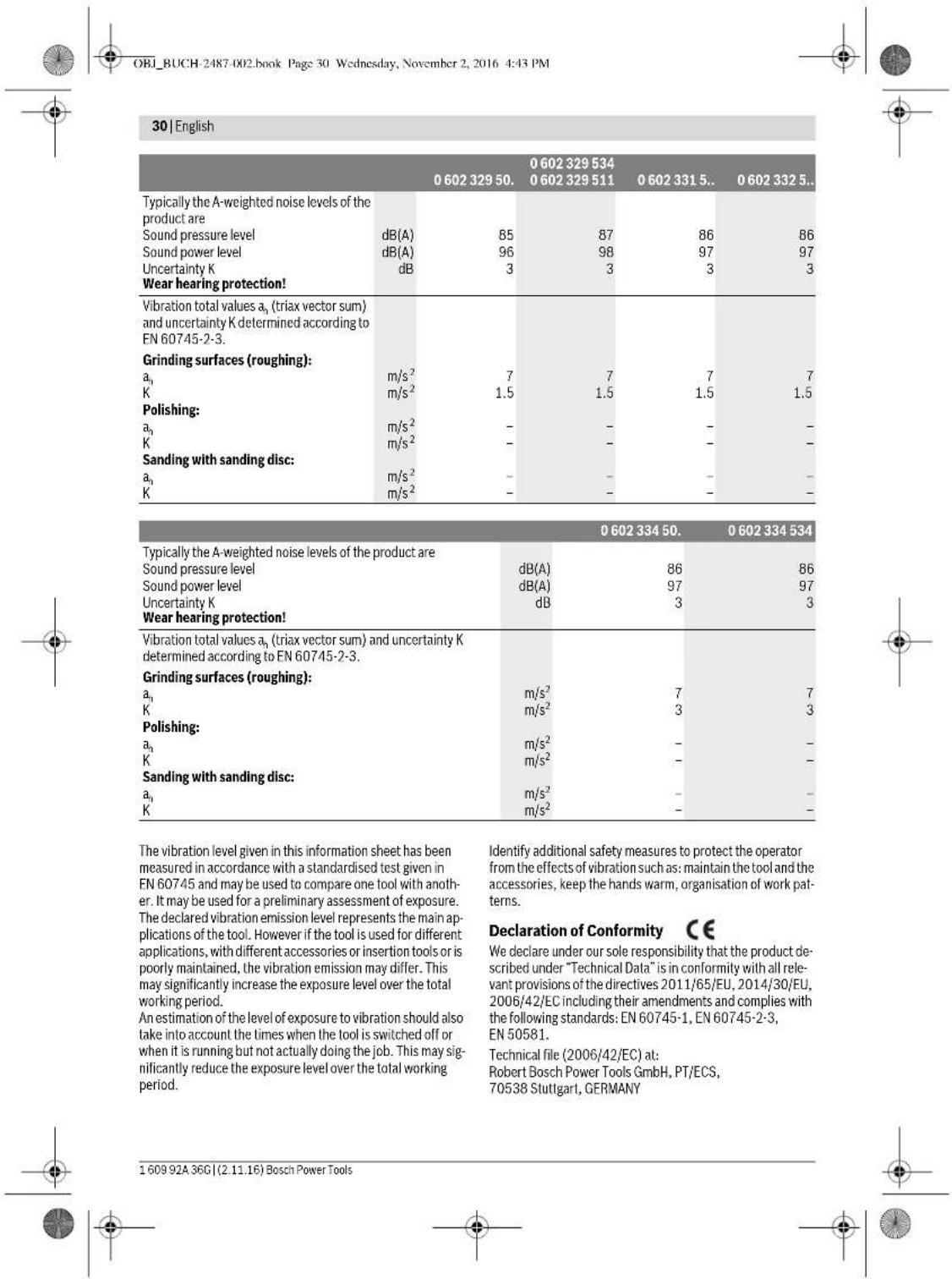
Noise/Vibration Information
Sound emission values determined according to EN 60745-2-3.
| 0 602 301 40. | 0 602 301 434 | 0 602 304 40. | 0 602 305 40. | |
| Typically the A-weighted noise levels of the product are | ||||
| Sound pressure level | dB(A) | 72 | 82 | 79 |
| Sound power level | dB(A) | 83 | 93 | 90 |
| Uncertainty K | dB | 3 | 3 | 3 |
| Wear hearing protection! | ||||
| Vibration total values \( a_{\mathrm {n}} \)(triax vector sum) and uncertainty K determined according to EN 60745-2-3. | ||||
| Grinding surfaces (roughing): | ||||
| \( a_{\mathrm {n}} \) | m/s2 | - | 5.3 | 5 |
| K | m/s2 | - | 2 | 2 |
| Polishing: | ||||
| \( a_{\mathrm {n}} \) | m/s2 | 3 | 3 | - |
| K | m/s2 | 1.5 | 1.5 | - |
| Sanding with sanding disc: | ||||
| \( a_{\mathrm {n}} \) | m/s2 | 3 | 3 | - |
| K | m/s2 | 1.5 | 1.5 | - |
| 0 602 306 434 | 0 602 324 40. | 0 602 324 44,0 602 324 4640 602 324 4740 602 324 434 | |
| Typically the A-weighted noise levels of the product are | |||
| Sound pressure level dB(A) | 82 | 77 | 82 |
| Sound power level dB(A) | 93 | 88 | 93 |
| Uncertainty K dB | 3 | 3 | 3 |
| Wear hearing protection! | |||
| Vibration total values \( a_h \) (triax vector sum) and un-certainty K determined according to EN 60745-2-3. | |||
| Grinding surfaces (roughing): | |||
| \( a_h \)m/s2 | - | - | 6 |
| Km/s2 | - | - | 2 |
| Polishing: | |||
| \( a_h \)m/s2 | < 2.5 | 4 | - |
| Km/s2 | 1.5 | 1.5 | - |
| Sanding with sanding disc: | |||
| \( a_h \)m/s2 | < 2.5 | 4 | - |
| Km/s2 | 1.5 | 1.5 | - |


Henk Becker
Executive Vice President Engineering
Heimut Heinzelmann
Head of Product Certification PT/ECS
Robert Bosch Power Tools GmbH
70538 Stuttgart, GERMANY
Stuttgart, 01.01.2017
Assembly
Mounting the Protective Devices
General Information
- Disconnect the power supply before making any adjustments, changing accessories, or placing the machine aside. This safety measure prevents accidental starting of the power tool.
Note: After breakage of the grinding disc during operation or damage to the holding fixtures on the protection guard/power tool, the machine must promptly be sent to an after-sales service agent for maintenance. For addresses, see section "After-sales Service and Application Service".
Adjust protection guards in such a manner that sparking toward the operator is prevented.
Note: The encoding keys of the protection guards ensure that only a protection guard that fits the machine type can be mounted.
Protection Guard for Grinding (see figure A)
Applies for the following types:
-060230440. -06023295.. -0602324434 -06023315.. -060232444. -06023325.. -0602324464 -06023345. -0602324474
- Place the protection guard 6 with the encoding key 8 engaging into the groove on the spindle collar 4 until the shoulder of the protection guard is seated against the flange of the power tool.
- Adapt the position of the protection guard to the requirements of the work step.
- Secure the protection guard by tightening locking screw 7 with a tightening torque of at least 10 Nm.
Protection Guard for Cutting
Applies for the following types:
-060230440. -06023295.. -0602324434 -06023315.. -060232444. -06023325.. -0602324464 -06023345.. -0602324474
For cutting with bonded abrasives, always use a protection guard for cutting. For cutting stone, always use a cutting guide with dust extraction protection guard (accessory).
The protection guards for cutting are mounted analogue to the standard protection guards (see figure A).
Vibration-dampening
Auxiliary Handle
(see figure B)
The vibration-dampening auxiliary handle reduces the vibrations, making operation more comfortable and secure.
Operate your machine only with the auxiliary handle 2. - Screw the auxiliary handle 2 on the right or left of the machine head depending on the working method. Do not make any alterations to the auxiliary handle. Do not continue to use an auxiliary handle if it is damaged.
Hand Guard (see figure C)
Applies for the following types: -06023014.. -060232440. -060230540. -0602306434
For operations with the rubber sanding plate 17 or with the cup brush/wheel brush/flap disc, always mount the hand guard 9. The hand guard 9 is fastened with the auxiliary handle 2.
Mounting the Grinding Tools
General Information
Disconnect the power supply before making any adjustments, changing accessories, or placing the machine aside. This safety measure prevents accidental starting of the power tool.
Pay attention to the dimensions of the grinding tools. The mounting hole diameter must fit the mounting flange without play. Do not use reducers or adapters. Clean the grinder spindle 3 and all parts to be mounted. After mounting the grinding tool and before switching on, check that the grinding tool is correctly mounted and that it can turn freely. Make sure that the grinding tool does not graze against the protection guard or other parts.
Mounting Grinding or Cutting Discs (see figures D1-D2)
Applies for the following types:
-060230440. -06023315.. -060232444,..464 -06023325. 474.434 -06023345
-06023295..
Installation
- Make sure that the fitting protection guard is mounted (see "Mounting the Protective Devices", page 31).
- Place the clamping flange 10 on the grinder spindle 3. A plastic part (O ring) is fitted around the centring collar of mounting flange 10. If the O-ring is missing or damaged, it must immediately be replaced before mounting flange 10 is mounted.
- Mount the desired grinding/cutting disc 11 in the correct rotation direction onto the grinder spindle 3.
Bosch Power Tools 1609 92A 36C (2.11.16)




OBI_BUCH-2487-002.book Page 32 Wednesday, November 2, 2016 4:43 PM
32|English
- Place the clamping nut 12 onto the spindle thread so that the central recess of the clamping nut faces upward. Tighten the clamping nut with two-pin spanner 13, while counter-holding the spanner surfaces of the grinder spindle 3 with open-end spanner 14.
Removal
Hold the grinder spindle 3 on the spanner surfaces with open-end spanner 14. - Unscrew the clamping nut 12 from the grinder spindle with two-pin spanner 13, while counter-holding the spanner surfaces with open-end spanner 14. - Afterwards, pull the grinding tool and the mounting flange from the grinder spindle.
Machines with Spindle Lock Button 5
Applies to the following types:
-060232440, -0602324434, -060232444.
For machines with spindle lock button 5, counter-holding with an open-end spanner is not required when mounting grinding tools (see figures E1-E2).
- Actuate the spindle lock button only when the grinder spindle is at a standstill. Otherwise, the machine may become damaged.
- Before installing or removing the grinding tool, press and hold spindle lock button 5 to lock the grinder spindle 3 in place.
- Mount the desired grinding tool (see "Mounting Grinding or Cutting Disks", page 31).
- Let go of the spindle lock button 5 to release the locked grinder spindle.
Mounting the Rubber Sanding Plate (see figure F)
Applies to the following types:
-06023014, -060232440, -060230540, -0602306434
Installation
- Make sure that the hand guard and the auxiliary handle are mounted (see "Mounting the Protective Devices", page 31).
- Place the rubber sanding plate 17 onto the grinder spindle 3. Lay the sanding disc 16 on the rubber sanding plate.
- Place the round nut 15 on the spindle collar.
- Tighten the round nut with two-pin spanner 13, while counter-holding the spanner surfaces of the grinder spindle 3 with open-end spanner 14.
Take care that the round nut 15 is screwed completely into the bulge of the rubber sanding plate so that it does not interfere while sanding and the sanding disc is firmly seated.
Removal
Hold the grinder spindle 3 on the spanner surfaces with open-end spanner 14.
- Unscrew the round nut 15 from the grinder spindle with two-pin spanner 13, while counter-holding the spanner surfaces with open-end spanner 14.
- Pull the sanding disc and the rubber sanding plate from the grinder spindle.
Mounting the Buffing Disc (see figure G)
Applies for the following types:
Pay attention that the thread of the buffing disc fits exactly on the grinder spindle thread (M14).
Make sure that the hand guard and the auxiliary handle are mounted (see "Mounting the Protective Devices", page 31). Screw the buffing disc 18 so far onto the grinder spindle 3 that it rests firmly against the face surface of the grinder spindle, while counter-holding the spanner surfaces of the grinder spindle 3 with open-end spanner 14.
Removal
- Unscrew the tightly seated buffing disc 18 from the grinder spindle by applying an open-end spanner to the buffing disc spanner surfaces, while counter-holding the spanner surfaces of the grinder spindle 3 with open-end spanner 14.
Mounting Wire Brushes (see figure H)
Applies to the following types:
-060230440, -06023315, -060232444, -060232464, -06023325, -06023345
-06023295
Installation
Pay attention that the thread of the wire brush fits exactly on the grinder spindle thread (M14).
Make sure that the hand guard and the auxiliary handle are mounted (see "Mounting the Protective Devices", page 31). Screw the desired wire brush 19 (cup brush or wire wheel) so far onto the grinder spindle 3 that it rests firmly against the face surface of the grinder spindle, while counter-holding the spanner surfaces of the grinder spindle with open-end spanner 14.
Removal
- Unscrew the tightly seated wire brush 19 from the grinder spindle by applying an open-end spanner to wire brush spanner surfaces, while counter-holding the spanner surfaces of the grinder spindle 3 with open-end spanner 14.
Dust/Chip Extraction
Dusts from materials such as lead-containing coatings, some wood types, minerals and metal can be harmful to one's health. Touching or breathing-in the dusts can cause allergic reactions and/or lead to respiratory infections of the user or bystanders.



Certain dusts, such as oak or beech dust, are considered as carcinogenic, especially in connection with wood-treatment additives (chromate, wood preservative). Materials containing asbestos may only be worked by specialists. - As far as possible, use a dust extraction system suitable for the material. - Provide for good ventilation of the working place. - It is recommended to wear a P2 filter-class respirator. Observe the relevant regulations in your country for the materials to be worked. Prevent dust accumulation at the workplace. Dusts can easily ignite.
Connection to the Power Supply
For operation of the power tools, a frequency converter is required that generates three-phase current with a frequency according to that listed on the type plate.
Frequency converters are available in various sizes, with different frequencies, secondary voltages and rated outputs. The choice of the frequency converter depends on the power tools to be connected. When selecting a frequency converter, contact your Bosch-specialist shop for advice.
The machine is provided with a four meter long specialty cable without plug. To put it into operation, the specialty cable must be equipped with a four-pole CEE plug (identification colour green).
Additionally, the machine can be equipped with a commercially available motor protection switch for protection against overload. The adjustment range of the motor protection switch must cover the nominal current of the power tool (see "Technical Data"). The motor protection switch must react in less than one second.
Please observe the safety warnings and assembly instructions in the operating instructions of the motor protection switch!
Mounting the CEE Plug (see figures 11-12)
- Loosen the two screws 22 and pull the plug insert 21 out of the plug housing of the CEE plug 24. Cut off the plastic sleeve 25 according to the diameter of the specialty cable of the power tool and insert the specialty cable through the CEE plug housing.
- Insert the four conductors through the cable strain relief 20.
- Loosen the four small screws 23 in the plug insert 21 and insert
the conductor ferrule of the brown L1 conductor into contact tube L1.
the conductor ferrule of the blue L2 conductor into contact tube L2,
the conductor ferrule of the black L.3 conductor into contact tube L3.
and the conductor ferrule of the green/yellow conductor into the earthing contact tube
- Firmly tighten the four small screws 23 in the plug insert 21 to affix the conductors. Now, tighten the screws of the cable strain relief 20 so that the cable clamp goes around the complete cable sheath, ensuring that no pressure is on the conductor ferrules.
- Reinsert plug insert 21 into the housing of the CEE plug 24 and tighten both screws 22 again.
- Afterwards, check the proper function of the protective conductor.
- Insert the CEE plug 24 of the power tool into the connection socket of the frequency converter.
Now, connect the frequency converter to the power supply. For information on how to connect the frequency converter to the power supply, see the frequency converter operating instructions.
Afterwards, check the rotation direction!
Checking the Rotation Direction
The rotation direction of the grinder spindle must correspond with the arrow on the power tool.
If the grinder spindle rotates in the wrong direction when putting into operation for the first time (see "Switching the Power Tool On/Off", page 34), switch the power tool off immediately and disconnect it from the power supply.
- Loosen the two screws 22 again and pull the plug insert 21 out of the plug housing of the CEE plug 24.
- Loosen the conductor ferrules of the black and brown conductors from their contact tubes.
- Now, insert the conductor ferrule of the black conductor L3 into contact tube L1, and the conductor ferrule of the brown conductor L1 into contact tube L3.
- Firmly tighten the small screws 23 in the plug insert 21 to affix the conductors.
- Reinsert plug insert 21 into the housing of the CEE plug 24 and tighten both screws 22 again.
- Afterwards, check the proper function of the protective conductor.
- Reconnect the power tool to the power supply.
Operation
Starting Operation
The voltage and frequency of the power source must correspond with the data on the type plate of the power tool. Check grinding tools before using. The grinding tool must be mounted properly and be able to move freely. Carry out a test run for at least one minute with no load. Do not use damaged, out-of-centre or vibrating grinding tools. Damaged grinding tools can burst and cause injuries. If the machine should unexpectedly stop operating even though the On/Off switch 1 is in the "On" position, set the On/Off switch to "Off". This will prevent uncontrolled restarting of the machine. Before restarting the machine, check the power supply (see "Connection to the Power Supply", page 33). Always connect the power tool to the frequency converter first, before connecting the frequency converter to the mains supply. To save energy, only switch the power tool on when using it.




Switching the Frequency Converter On/Off
The frequency converter must be put into operation first before actuating the power tool.
For this, observe the operating instructions of the frequency converter.
Switching the Power Tool On/Off with the On/Off Switch (see figure J1)
Applies for the following types:
-06023244.
- To start the machine, push the On/Off switch 1 forwards.
- To lock the On/Off switch 1, press the On/Off switch 1 down at the front until it latches.
- To switch off the power tool, release the On/Off switch 1. When the On/Off switch 1 is locked-on, briefly press it toward the rear and then release it.
Switching the Power Tool On/Off
with Safety Switch (see figure J2)
Applies to the following types:
-06023014, -06023295, -060230440, -06023315, -060230540, 06023325, -0602306434, -06023345
To start the power tool, press the On/Off switch 1 forward and then down. To lock the pressed On/Off switch 1, push it further forward. To switch off the power tool, release the On/Off switch 1, or if it is locked, briefly press the On/Off switch 1 and then release it.
Working Advice
- Disconnect the power supply before making any adjustments, changing accessories, or placing the machine aside. This safety measure prevents accidental starting of the power tool. Exercise caution when cutting slots in structural walls; see Section "Information on Structures".
- Clamp the workpiece if it does not remain stationary due to its own weight. Do not strain the machine so heavily that it comes to a standstill. After heavily straining the power tool, continue to run it at no-load for several minutes to cool down the accessory.
Sanding with the Flap Disc
With the flap disc (accessory), curved surfaces and profiles can be worked.
Flap discs have a considerably higher service life, lower noise levels, and lower sanding temperatures than conventional sanding sheets.
Cutting Metal (see figure K)
For cutting with bonded abrasives, always use a protection guard for cutting.
When cutting, work with moderate feed, adapted to the material being cut. Do not exert pressure onto the cutting disc, tilt, or oscillate the machine.
Do not reduce the speed of running down cutting discs by applying sideward pressure. The machine must always work in an up-grinding motion. Otherwise, the danger exists of it being pushed uncontrolled out of the cut. When cutting profiles and square bar, it is best to start at the smallest cross section.
Cutting Stone
- Provide for sufficient dust extraction when cutting stone. Wear a dust respirator. The machine may be used only for dry cutting/grinding.
For cutting stone, it is best to use a diamond cutting disc. For safety against jamming, a special cutting guide with dust extraction protection guard (accessory) must be used. Operate the machine only with dust extraction and additionally wear a dust protection mask. The vacuum cleaner must be approved for the extraction of masonry dust. Bosch provides suitable vacuum cleaners. - Switch on the machine and place the front part of the cutting guide on the workpiece. Slide the machine with moderate feed, adapted to the material to be worked. For cutting especially hard material, e.g., concrete with high pebble content, the diamond cutting disc can overheat and become damaged as a result. This is clearly indicated by circular sparking, rotating with the diamond cutting disc. In this case, interrupt the cutting process and allow the diamond cutting disc to cool by running the machine for a short time at maximum speed with no load. Noticeably decreasing work progress and circular sparking are indications of a diamond cutting disc that has become dull. Briefly cutting into abrasive material (e.g., lime-sand brick) can reshappen the disc again.
Information on Structures
Slots in structural walls are subject to the Standard DIN 1053 Part 1, or country-specific regulations. These regulations are to be observed under all circumstances. Before beginning work, consult the responsible structural engineer, architect or the construction supervisor.
Rough Grinding
Never use a cutting disc for roughing.
The best roughing results are achieved when setting the machine at an angle of 30° to 40°. Move the machine back and forth with moderate pressure. In this manner, the workpiece will not become too hot, does not discolour and no grooves are formed.
Sanding with Sanding Discs and the Rubber Sanding Plate
The choice of the suitable sanding paper depends on the material to be worked.
Bosch offers various sanding-paper qualities that fit the rubber sanding plate. Contact your specialist shop for advice.
Gauteng - BSC Service Centre
35 Roper Street, New Centre
Johannesburg
Tel.: (011) 4939375
Fax: (011) 4930126
E-Mail: bsctools@icon.co.za
KZN - BSC Service Centre
Unit E, Almar Centre
143 Crompton Street
Pinetown
Tel.: (031) 7012120
Fax: (031) 7012446
E-Mail: bsc.dur@za.bosch.com
Western Cape - BSC Service Centre
Democracy Way, Prosperity Park
Milnerton
Tel.: (021) 5512577
Fax: (021) 5513223
E-Mail: bsc@zsd.co.z
Bosch Headquarters
Midrand, Gauteng
Tel.: (011) 6519600
Fax: (011) 6519880
E-Mail: rbsa-hq.pts@za.bosch.com
Disposal
The machine, accessories and packaging should be sorted for environmental-friendly recycling.
Do not dispose of power tools into household waste!
Only for EC countries:
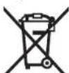
According to the European Directive 2012/19/EU for Waste Electrical and Electronic Equipment and its implementation into national right, power tools that are no longer usable must be collected separately and disposed of in an environmentally correct manner.
Subject to change without notice.
French 45
OBI_BUCH-2487-002.book Page 46 Wednesday, November 2, 2016 4:43 PM
46 | French
Executive Vice President
Engineering
Helmut Heinzelmann
Head of Product Certification
PT/ECS
iV. h = mc
Robert Bosch Power Tools GmbH
70538 Stuttgart, GERMANY
Stuttgart, 01.01.2017
Assembly
OBI_BUCH-2487-002.book Page:61 Wednesday, November 2, 2016 4:43 PM
Henk Becker Helmut Heinzelmann Executive Vice President Head of Product Cert Engineering PT/ECS

Robert Bosch Power Tools GmbH
70538 Stuttgart, GERMANY
Stuttgart, 01.01.2017
Assembly
62 | Spanish
4hastra'spectarcelollarde lacapuera protectorca contra lbrida de la herramanta electrica.
Spanish | 65
-06023014.. -06023295.. -060230440. -06023315.. -0.60230540 -0.6023325 -0602306434 -06023345..
Portuguese 75
Executive Vice President
Engineering
Helmut Heinzelmann
Head of Product Certification

Robert Bosch Power Tools GmbH
70538 Stuttgart, GERMANY
Stuttgart, 01.01.2017
Assembly
reduces vibration
Italian|91
Executive Vice President Engineering
Helmut Heinzelmann
Head of Product Certification PT/ECS
i.v. k = m _____
Robert Bosch Power Tools GmbH 70538 Stuttgart, GERMANY Stuttgart, 01.01.2017
Bosch Power Tools 1609 92A 36C (2.11.16)


94 Italian
Assembly
Dutch | 99
104 Dutch
Dutch | 107
Dutch | 109
Henk Becker Helmut Heinzelmann Executive Vice President Head of Product Certification Engineering PT/ECS

Robert Bosch Power Tools GmbH 70538 Stuttgart, GERMANY Stuttgart, 01.01.2017
Assembly
110 | Dutch
Dansk | 123
| 0 602 329 50. | 0 602 329 534 | 0 602 331 5.. | 0 602 332 5.. | ||
| 0 602 329 511 | |||||
| Samléde vibrationsværddier \( a_h \) (vektorsumfor tre retninger) og usikkerhed K beregnetiht. EN 60745-2-3. | |||||
| Overfladeslibning (skrubning): | |||||
| \( a_h \) | \( m/s^2 \) | 7 | 7 | 7 | 7 |
| K | \( m/s^2 \) | 1,5 | 1,5 | 1,5 | 1,5 |
| Polering: | |||||
| \( a_h \) | \( m/s^2 \) | - | - | - | - |
| K | \( m/s^2 \) | - | - | - | - |
| Slibning med silbeblad: | |||||
| \( a_h \) | \( m/s^2 \) | - | - | - | - |
| K | \( m/s^2 \) | - | - | - | - |
| 0 602 334 50. | 0 602 334 534 | |
| Værktajets A-vurdere lydtrykniveau er typisk | ||
| Lydtrykniveau | dB(A) | 86 |
| Lydeffektniveau | dB(A) | 97 |
| Usikkerhed K | dB | 3 |
| Brug horevaarn! | ||
| Samlke vibrationsværddier \( a_{i} \) (vektorsum for tre retninger) ogusikkerhed K beregnet iht. EN 60745-2-3. | ||
| Overfladeslibning (skrubning): | ||
| \( a_{i} \) | \( m/s^2 \) | 7 |
| K | \( m/s^2 \) | 3 |
| Polering: | ||
| \( a_{i} \) | \( m/s^2 \) | - |
| K | \( m/s^2 \) | - |
| Slibning med silbeblad: | ||
| \( a_{i} \) | \( m/s^2 \) | - |
| K | \( m/s^2 \) | - |
Executive Vice President
Engineering
Helmut Heinzelmann
Head of Product Certification
PT/ECS

Robert Bosch Power Tools GmbH
70538 Stuttgart, GERMANY
Stuttgart, 01.01.2017
Assembly
132 | Swedish
-060232444,464.474.434
-06023295.. -06023315.. -06023325 -06023345..
| Högtfrekvensvinkelslipar | ||||||
| Märkström A | 5 | 10 18 10 27 | ||||
| Tomgängsvartval | min1 | 6600 | 6600 | 6600 | 6600 | |
| max. slipskivsdiameter | mm 230 | 230 | 230 | 230 | ||
| Slipspindelgänga | M14 | M14 | M14 | M14 | ||
| Vikt enligt EPTA-Procedure 01:2014 - med vibrationsdämpande stöchhandtag | kg | 7,1 | 7,1 | 7,1 | 7,1 | 7,1 |
| Skyddsklass | ± /I | ± /I | ± /I | ± /I | ± /I | |
| Kapslingsklass | IP 20 | IP 20 | IP 20 | IP 20 | IP 20 | |
| Högfrektvensvinkelslipar | |||||
| Artikelnummer | 0 602 334 ... | ||||
| ... 501 | ... 504 | ... 507 | ... 534 | ||
| Märksprüning | V | 265 | 135 | 72 | 200 |
| Frekvens | Hz | 200 | 200 | 200 | 300 |
| Upptagen märkeffekt | W | 2500 | 2500 | 2500 | 3800 |
| Avgiven märkeffekt | W | 2200 | 2200 | 2200 | 3100 |
| Märkström | A | 6,7 | 13,2 | 24,7 | 13,2 |
| Tomgangsvarval | min1 | 6600 | 6600 | 6600 | 6600 |
| max. slipskivsdiameter | mm | 230 | 230 | 230 | 230 |
| Slippspindelgänga | M14 | M14 | M14 | M14 | |
| Vikt enligt EPTA-Procedure 01:2014 - med vibrationsdämpande stödhandtag | kg | 7,8 | 7,8 | 7,8 | 7,8 |
| Skyddsklass | #/1 | #/1 | #/1 | #/1 | |
| Kapslingsklass | IP 20 | IP 20 | IP 20 | IP 20 | |
Henk Becker Executive Vice President Engineering
Helmut Heinzelmann Head of Product Certification PT/ECS

Robert Bosch Power Tools GmbH 70538 Stuttgart, GERMANY Stuttgart, 01.01.2017
Montage
138 | Swedish
Vibration-damping auxiliary handle (see figure B)
140 | Swedish
Bosch Service Center
Telegrafvej 3
2750 Ballerup
Denmark
Tel.: (08) 7501820 (in Sweden)
Fax: (011) 187691
Waste disposal
Applies to all types



Norwegian | 149
Finnish | 159
Finnish | 163
| 0602 301 40. | 0602 301 434 | 0602 304 40. | 0602 305 40. | |
| Värähtely nhteisarvot a, (kolmen suunnan vektorisumma) ja epävarnuus K mitattuna EN 60745-2-3 mukaan. | ||||
| Pintahionta (karhennus): | ||||
| a, | m/s2 | - | 5,3 | 5 |
| K | m/s2 | - | 2 | 2 |
| Kiillotus: | ||||
| a, | m/s2 | 3 | 3 | - |
| K | m/s2 | 1,5 | 1,5 | - |
| Honta hiomapaperilla: | ||||
| a, | m/s2 | 3 | 3 | - |
| K | m/s2 | 1,5 | 1,5 | - |
164 | Finnish
Executive Vice President Engineering
Helmut Heinzelmann
Head of Product Certification PT/ECS
Therefore V.H = W_c
Robert Bosch Power Tools GmbH
70538 Stuttgart, GERMANY
Suomi | 165
-060230440. -06023295.. -0602324434 -06023315.. -060232444. -06023325.. -0602324464 -06023345.. -0602324474
Instructions for use:
174|Greek
Description of the product and its power

Read all safety warnings and all instructions. Failure to follow the warnings and instructions may result in electric shock, fire and/or serious injury.
Please open the fold-out page with the illustration of the product and keep it open while reading the operating instructions.
Using the product
Instructions for use:
-06023014 -060230540 -0602306434 -060232440.
This power tool is intended for cutting and grinding metal and stone materials with the use of appropriate accessories.
It is intended for the following types:
-060230440 -060232444,...464,...474,...434 -06023295. -0.6023315 -0.6023325 -06023345.
The power tool is intended for cutting, roughing, and brushing metal and stone materials without the use of water.
For the respective material, a suitable accessory must be used.
For the respective application, the appropriate accessory must be used.
It is suitable for both types.
It is permitted to use only accessories that are approved by the manufacturer for this power tool and that are suitable for the intended use.
| 0602 334 50. | 0602 334 534 | |
| Ötouyolçük tüpec kpaşağmá yı. (şθροιασa ayucaŋaw trpov katcu-θυσεων) kai avaşpalaia K εξακρβωθηκav σύμφωνa μe to npɔ:tuno EN 60745-2-3. | ||
| Aciavon emφavcew (ξεχόνδριαμα): | ||
| a1 | m/s2 | 7 |
| K | m/s2 | 3 |
| Σιλβωση: | ||
| a1 | m/s2 | - |
| K | m/s2 | - |
| Aciavon μe συμρίδαχρτο: | ||
| a1 | m/s2 | - |
| K | m/s2 | - |
The power tool is intended for cutting and grinding metal and stone materials with the use of appropriate accessories. It is essential to use the correct type of accessory for the material being worked on.
The power tool is intended for cutting and grinding metal and stone materials. The power tool is suitable for use with various accessories, depending on the application. The power tool must be used with the appropriate accessory for the specific task.
The power tool is intended for cutting and grinding metal and stone materials. The power tool is suitable for use with various accessories, depending on the application. The power tool must be used with the appropriate accessory for the specific task.
For this reason, before starting work, the operator must take appropriate safety measures to protect themselves. The power tool must be used with the correct accessory and the appropriate safety equipment.
The power tool is suitable for use with various accessories, depending on the application. The power tool must be used with the appropriate accessory for the specific task. The power tool is intended for cutting and grinding metal and stone materials. The power tool is suitable for use with various accessories, depending on the application. The power tool must be used with the appropriate accessory for the specific task.
Robert Bosch Power Tools GmbH, PT/ECS, 70538 Stuttgart, GERMANY
Henk Becker Helmut Heinzelmann Executive Vice President Head of Product Certification Engineering PT/ECS
Robert Bosch Power Tools GmbH 70538 Stuttgart, GERMANY Stuttgart, 01.01.2017
Sigma
Declaration of Conformity
Revised
We declare under our sole responsibility that the product described under “Technical Data” complies with the relevant regulations, provided that the electrical tool is used in accordance with the instructions. This product is marked with the CE symbol.
If the power tool is used for a long period of time, the safety instructions must be followed. If the power tool is damaged, it must be repaired by the Service. For the spare parts, please contact the Service and provide the type designation.
Keep the power tool away from rain and moisture.
The power tool is double insulated for protection against electric shock, so no grounding is required.
The product is suitable for the following types:
-060230440. -06023295.. -0602324434 -06023315.. -060232444. -06023325.. -0602324464 -06023345.. -0602324474 The product is marked with the CE symbol and the type designation.
180|Greek
Technical data for the product are given in the operating instructions.
Lay the tool on a flat surface:
-06023014.. -060232440. -060230540. -0602306434
Button
Remove the protective cover from the product and the protective cover from the product (see Figure 2). Remove the protective cover from the product and the protective cover from the product. The product is equipped with a 16 A fuse. The product is equipped with a 15 A fuse. Insert the plug into the socket 13, while simultaneously pressing the switch 14 to the ON position. Then, insert the plug into the socket 15 according to the diagram of the fuse holder, so that it is connected correctly and the fuse is protected.
Removal
-Remove the fuse holder 3 before inserting the fuse. -Insert the plug 10 into the socket 13 as shown in the figure, while simultaneously pressing the switch 14 to the ON position. -Remove the fuse holder and the fuse holder from the fuse holder.
Connection of the power supply (see figure)
Instructions for use:
OBI_BUCH-2487-002.book Page 183 Wednesday, November 2, 2016 4:43 PM
English183
Connect the power tool to the power supply using the transformer, and set the transformer to the correct voltage.
Keep the power tool away from moisture and do not use it in wet conditions. Risk of electric shock.
Switching on/off of the transformer
Before putting the transformer into operation, you must first switch on the power tool.
Please note the operating instructions of the transformer.
See the enclosed operating instructions for the electrical connection.
It is suitable for the following types:
- 06023244 - Via the electrical connection, the device switches the ON/OFF switch 1 to the socket. To switch the ON/OFF switch 1, press the ON/OFF switch 1 until it switches. The remote control is
controlled by the ON/OFF switch 1, which is set to the socket and is switched on and off.
See the electrical connection for the socket operation.
| Yüksek frekansl taşlama makinesi | |||||
| Urdın kodu | 0 602 334 ... | ||||
| ... 501 | ... 504 | ... 507 | ... 534 | ||
| Anma gerilimi | V 265 135 72 200 | ||||
| Frekans | Hz 200 200 200 300 | ||||
| Girgis Güçü | W 2500 2500 2500 3800 | ||||
| Çkış Güçü | W 2200 2200 2200 3100 | ||||
| Anma akimi | A 6 | , | 7 | 13,2 24,7 13,2 | |
| Bostaki devirsaysı | dev/dak 6600 6600 6600 6600 | ||||
| Maks. taşlama disiki çapı | mm 230 230 230 230 | ||||
| Taşlama mili disi | M14 M14 M14 M14 | ||||
| Ağırkı EPTA-Procedure 01:2014'e gère - Titresjm onleyici ek tutamakla | kg 7,8 | 7,8 | 7,8 | 7,8 | |
| Korum sunifi | ®/I | ®/I | ®/I | ®/I | |
| Korum tişi | IP 20 | IP 20 | IP 20 | IP 20 | |
Information on the power supply
The power tool is part of a high-frequency system and requires a 3-phase alternating current with the frequency specified on the type plate.
To achieve this frequency, the power tool must be connected to a frequency converter (see "Connection to the power supply", page 196).
| 0 602 306 434 | 0 602 324 40. | 0 602 324 44. | |
| 0 602 324 464 | |||
| 0 602 324 474 | |||
| 0 602 324 434 | |||
| Toplam titreşimiGeorge tergeleri a.(iççın)...ve tolerans K, EN 60745-2-3 uyarınca.Yüsey taşlama(kazıma): | |||
| a1m/s2- | - | - | 6 |
| Km/s2- | - | - | 2 |
| Polisaj: | |||
| a1m/s2<2.5 | 4 | - | |
| Km/s21.5 | 1.5 | 1.5 | - |
| Zimpara kalık ilezimpara: | |||
| a1m/s2<2.5 | 4 | - | |
| Km/s21.5 | 1.5 | 1.5 | - |
The specified vibration level is representative of the basic applications of the power tool. If the power tool is used for other applications, with different accessories, with different tools, or with insufficient maintenance, the vibration level may differ from the specified value. This may significantly increase the vibration load over the total working time.
To be able to estimate the vibration load, the time during which the tool is switched off or is running but not actually used must also be taken into account. This can significantly reduce the vibration load over the total working time.
Take additional safety measures to protect the operator from the effects of vibration, such as: maintaining the power tool and accessories, keeping hands warm, and organizing work processes.
Declaration of Conformity
Henk Becker Helmut Heinzelmann Executive Vice President Head of Product Certification Engineering PT/ECS
Robert Bosch Power Tools GmbH 70538 Stuttgart, GERMANY Stuttgart, 01.01.2017
Assembly
Polish 203
204| Polish
Polish 207
Executive Vice President Engineering
Helmut Heinzelmann
Head of Product Certification PT/ECS
Robert Bosch Power Tools GmbH 70538 Stuttgart, GERMANY Stuttgart, 01.01.2017
Bosch Power Tools 1609 92A 36C (2.11.16)


Polish 211
Robert Bosch Sp. z.o.o.
Czech | 219
with electric shock, risk of fire or serious injury.
Czech | 223
Henk Becker, Helmut Heinzelmann, Executive Vice President, Head of Product Certification Engineering PT/ECS
Robert Bosch Power Tools GmbH, 70538 Stuttgart, GERMANY, Stuttgart, 01.01.2017
Assembly
Cutting metal (see figure K)
For cutting with bonded abrasives, always use the protective guard for cutting.
When cutting, work with moderate feed, adapted to the material being machined. Do not exert pressure on the cutting disc, do not tilt or oscillate it.
Do not brake the cutting disc by applying lateral pressure. The power tool must always be guided in the opposite direction of the cutting disc rotation. Otherwise, there is a risk of uncontrolled ejection from the cut.
When cutting profiles and square bars, it is best to start at the smallest cross-section.
Cutting stone
When cutting stone, ensure adequate dust extraction. Wear a dust protection mask. The power tool may only be used for dry cutting/grinding.



For cutting stone, it is best to use diamond cutting discs. As a safety measure, the protective guard for cutting with guide rail must be used.
Grinding with sanding paper on a sanding plate
Bosch Service Center PT
KVapence 1621/16
69201 Mikulov
On www.bosch-pt.cz you can order the repair of your
Slovak | 237
Information on power supply
This power tool is part of a high-frequency system and requires three-phase alternating current with a frequency according to the type plate.
To achieve this frequency, the high-frequency power tool must be connected to a frequency converter (see "Connection to power supply", page 241).
238 | Slovak
| 0 602 329 50. | 0 602 329 534 | 0 602 331 5.. | 0 602 332 5.. | ||
| 0 602 329 511 | |||||
| Vyhodnotená hodnota hladny hluku A výrobku je typicky Hladina zvukového tlaku | dB(A) | 85 | 87 | 86 | 86 |
| Hladina akustického tlaku | dB(A) | 96 | 98 | 97 | 97 |
| Nepresnost merania K Používajte chraniče sluch! | dB | 3 | 3 | 3 | 3 |
| Celkové hodnoty vibráci a₃ (suma vektorov troch smerov) a nepresnost merania K zistovane podla normy EN 60745-2-3. Obrusovanie povrchovej plochy (hrubovanie): | |||||
| a₃ | m/s² | 7 | 7 | 7 | 7 |
| K | m/s² | 1.5 | 1.5 | 1.5 | 1.5 |
| Leštenie: | |||||
| a₃ | m/s² | - | - | - | - |
| K | m/s² | - | - | - | - |
| Brúsenie brúsnym listom: | |||||
| a₃ | m/s² | - | - | - | - |
| K | m/s² | - | - | - | - |
| 0 602 334 50. | 0 602 334 534 | ||
| VyhodnotaNá hodnota hladiny hluku A výrobk je typicky | |||
| Hladina zvukového tlaku | dB(A) | 86 | 86 |
| Hladina akustického tlaku | dB(A) | 97 | 97 |
| Nepresnost merania K | dB | 3 | 3 |
| Používajte chránice sluch! | |||
| Celkové hodnoty vibráci aₙ (suma vektorov troch smerov) a nepresnost merania K zistované podl'na normy EN 60745-2-3. | |||
| Obrusovanie pocrchovej plochy (hrubovanie): | |||
| aₙ | m/s² | 7 | 7 |
| K | m/s² | 3 | 3 |
| Leštenie: | |||
| aₙ | m/s² | - | - |
| K | m/s² | - | - |
| Brúsenie brùsnym listom: | |||
| aₙ | m/s² | - | - |
| K | m/s² | - | - |
The vibration level given in these instructions was measured according to the measuring procedure specified in EN 60745 and can be used for comparison of power tools. It is also suitable for a preliminary estimate of vibration exposure. The stated vibration level represents the main applications of this power tool. However, if the power tool is used for other applications, with different accessories, with different tools, or with insufficient maintenance, the vibration level may differ. This can significantly increase the vibration exposure over the total working period.
For an accurate estimate of vibration exposure during a certain period of work with the tool, the times when the tool is switched off or when it is running but not actually in use must also be taken into account. This can significantly reduce vibration exposure over the total working period.
To protect the person working with the tool from the effects of vibration load, additional safety measures should be taken.
Slovak 239
Robert Bosch Power Tools GmbH, PT/ECS, 70538 Stuttgart, GERMANY
Henk Becker
Executive Vice President Engineering
Heimut Heinzelmann
Head of Product Certification PT/ECS
Robert Bosch Power Tools GmbH
706.38 Stuttgart, GERMANY Stuttgart, 01.01.2017
Assembly
Assembly of protective components
OBI_BUCH-2487-002.book Page 240 Wednesday, November 2, 2016 4:43 PM
240 | Slovak
OBI_BUCH-2487-002.book Page 243 Wednesday, November 2, 2016 4:43 PM
Slovak 243
For cutting stone, we recommend using a diamond cutting disc. To protect against overheating, use the extraction guard for cutting with guide rails.
244 Hungarian
Accessories
For the complete range of high-quality accessories, you can find information on the internet at www.bosch-pt.com and www.boschproductiontools.com, or from your authorized dealer.
Service center and advice on use
252 Hungarian



Henk Becker Helmut Heinzelmann Executive Vice President Head of Product Certification Engineering PT/ECS

Robert Bosch Power Tools GmbH 70538 Stuttgart, GERMANY Stuttgart, 01.01.2017
Assembly
260|Russian
Russian
The set of operational documents provided with the product may include this operation manual, as well as appendices. Information about the approval of the conformity is corrected in the appendix.
Information about the origin of the product is indicated in the appendix.
The date of manufacture is indicated on the title page of the manual.
Contact information about the importer is contained on the packaging.
Service life
The service life is 5 years. It is not recommended to use the product after 5 years from the date of manufacture without prior inspection (see the date of manufacture on the label).
Do not use the device if the power cord or plug is damaged, or if the device has been dropped or damaged in any way. Do not use the device with a damaged power cord or plug. Do not use the device near water (e.g., in a bathtub, washbasin, or swimming pool). Do not use the device with wet hands. Do not use the device if the cord is frayed or damaged.
Criteria for limit states
- Damage to the power cord
- Damage to the device housing
Type and frequency of technical maintenance
The tool is designed for use with any type of call.
Storage
It is necessary to store in a dry place - avoid storing the device at elevated temperatures and under direct sunlight - storage temperature - storage in the packaging is not allowed - for detailed storage conditions, see GOST 15150 (clause 1).
Transportation
Categorically not allowed to drop or subject to mechanical impact on the packaging during transportation - during loading/unloading, the use of lifting equipment operating on the principle of gripping the packaging is allowed - for detailed transportation conditions, see GOST 15150 (clause 5).
Service life
The service life is 7 years. It is not recommended to use the device after 5 years of storage from the date of manufacture without prior verification (see the date of manufacture on the label).
List of critical failures affecting the safety of the user
- Use in a damaged housing without a protective cover is not allowed.
- Use with a broken or burnt electric cable is not allowed.
- Use in an open space during rain [in the rain] and in places with high humidity is not allowed, as water may get inside the housing. Use with a damaged housing is not allowed.
Criteria for limit states
- Breakage or damage to the electric cable
- Damage to the housing of the product
Periodicity of technical maintenance
RECOMMENDED INSTRUCTIONS FOR USE OF THE INSTRUMENT.
Storage
It is necessary to store in a dry place - do not allow storage in conditions of high humidity and exposure to extreme temperatures. During storage, it is necessary to avoid sharp temperature changes. Storage in packaging is not allowed - detailed requirements for storage conditions are given in GOST 15150 (Condition 1).
Transportation
Categorically, mechanical impacts on the instrument during transportation are not allowed - during loading/unloading, the use of lifting equipment operating on the principle of gripping packages is not allowed. Detailed requirements for transportation conditions are given in GOST 15150 (Condition 5).
Safety Instructions
General safety instructions for power tools
WARNING
Read all safety instructions and
instructions for use. Failure to follow the safety instructions and instructions for use may result in electric shock, fire, and serious injuries.
Save all instructions and safety instructions for future use.
The term "power tool" in these instructions refers to power tools powered by the mains (with a power cord).
Russian | 261

For cordless power tools (without a power cord).
Workplace safety
Keep your workplace clean and well lit. Cluttered or dark areas invite accidents. Never operate power tools in explosive atmospheres, such as in the presence of flammable liquids, gases, or dust. Power tools create sparks, which may ignite the dust or fumes. While operating a power tool, keep bystanders away from your work area. Distractions can cause you to lose control of the tool.
Electrical safety
Power tool plugs must match the outlet. Never modify the plug in any way. Do not use any adapter plugs with earthed (grounded) power tools. Unmodified plugs and matching outlets will reduce risk of electric shock. Avoid body contact with earthed surfaces, such as pipes, radiators, ranges, and refrigerators. There is an increased risk of electric shock if your body is earthed or grounded. Protect power tools against moisture. Water entering a power tool will increase the risk of electric shock. Never use the cord for carrying, pulling, or unplugging the power tool. Keep cord away from heat, oil, sharp edges, or moving parts. Damaged or entangled cords increase the risk of electric shock. When operating a power tool outdoors, use an extension cord suitable for outdoor use. Use of a cord suitable for outdoor use reduces the risk of electric shock. If operating a power tool in a damp location is unavoidable, use a residual current device (RCD) protected supply. Use of an RCD reduces the risk of electric shock.
Personal safety
Stay alert, watch what you are doing, and use common sense when operating a power tool. Do not use a power tool while you are tired or under the influence of drugs, alcohol, or medication. A
moment of inattention while operating power tools may result in serious personal injury.
Personal protective equipment for protection against electric shock. Use of personal protective equipment, such as: protective mask, footwear with non-slip soles, protective helmet or means of protecting the respiratory organs, depends on the type of work with the power tool and reduces the risk of injury. Before turning on the power tool, check that it is properly connected to the power supply and/or to the battery. Keep your finger off the switch when carrying the power tool. Connecting the power tool to the mains or turning it on while carrying it can lead to accidents. Remove the adjusting tool or wrench before turning on the power tool. A wrench or key left attached to a rotating part of the power tool can cause injury. Do not adopt an unnatural posture. Always maintain a stable stance and balance. This allows you to better control the power tool in unexpected situations. Wear suitable clothing. Do not wear loose clothing or jewelry. Keep your hair, clothing, and gloves away from moving parts. Loose clothing, jewelry, or long hair can get caught in moving parts. If dust extraction and collection equipment is available, ensure it is properly connected and used. Use of these devices can reduce dust-related hazards.
Power tool use and care
Do not overload the power tool. Use the correct power tool for your application. The correct power tool will do the job better and safer at the rate for which it was designed. Do not use the power tool if the switch does not turn it on and off. Any power tool that cannot be controlled with the switch is dangerous and must be repaired. Disconnect the plug from the power source and/or remove the battery pack from the power tool before making any adjustments, changing accessories, or storing power tools. Such preventive safety measures reduce the risk of starting the power tool accidentally. Store idle power tools out of the reach of children and do not allow persons unfamiliar with the power tool or these instructions to operate the power tool. Power tools are dangerous in the hands of untrained users.
Carefully maintain the power tool. Check for misalignment or binding of moving parts, breakage of parts, and any other condition that may affect the power tool's operation. If damaged, have the power tool repaired before use. Many accidents are caused by poorly maintained power tools. Keep cutting tools sharp and clean. Properly maintained cutting tools with sharp cutting edges are less likely to bind and are easier to control. Use the power tool, accessories, and tool bits, etc., in accordance with these instructions, taking into account the working conditions and the work to be performed. Use of the power tool for operations different from those intended could result in a hazardous situation.
Service
PemOHBaERo3nEeKPOHHCTpyMHTaNOPyAHTObnkoKBaHmHcHPOBAMHOHPcOHaYnTbKOcPNHMeHHeMOpHNHbHb3Na3aHbXuaCTe.3THMObeCneuBaTaETBe0anacchoCTb3nEeKPOHHCTpyMHTa.
Yka3aHHNoTexHKe6e3oNaChocTHdN yIIOBbIX WnHΦMaHH
06nue yka3aHn no TeXnKHe 6e3oNaChOCTn npn nnfoBaan HaxdaHoh 6yMaRo nnonpoBaHH
IeHCTBHTenbHO nA CnEduOuHX TnNOB:
-06023014.. -0.60230540 -0.602.306.434 -0.60232440
3OT3NEKTPOHNCTPYMENT PEPDAHAAHEN HINHNOFOBAMHAHNAHAXDAHNO BYMARO INONPOBAHN. IPNMMTE B0BHMANNE BCEYKAANAHNO TEXNHKE 6E3OJANACHTN, HNCTPKYUN, H3O6PAXKENH NADAHBE, KOTOPBE BNoIyNNHBMCECT CHCPTPYMHTOM. HecoNIOHNHEHXKcneLQUUXYkA3AHN UPEBAOTOPAKENEHNEIKPTPKC KHM TOKOM, POKAPOM HNIITTKENBIMTPABMAH. 3TOT3nKtpOnHCTpyMeHT He npHrOednIyIHHFOBAH, KpcaeBaHbN PPOBOHcyHbM IcEaKMn Hbpa3BbHO rOpTeaHn. IIpIMHeMeHHE 3nKtpOnHCTpyMeHTa No HsHa2HueHHIO UvBPATO ANCHOCTMR N TpBaAMn.
O6UeYyka3AHNO nTOxEHKKe 6eONACHOHn Pn HUNHPOBAMHN, KpaueBaHHN PpOBOnOHyBM NtETKaMMN A6pa3NB HOM OTePA3HHN
HcBtBnBHO Dn CnEduuXTHNOB:
-060230440 -060232444.464.474.434 -06023295. -06023315. -06023325. -06023345.
3OT3JNEKTOPHCHTymeHPTpeHDAHAUYHnIYNCIOB 3OBAHnA KVAECTeMHINBOAHOBHMOHANKHHN,POSO8
NoohHJIeKTHN H6pa3HBHO-0Te3HO MaHHKN. PnMHMe NT BO HAMHNE BCKA3HHN NO TEHXHE 6EONAOCHTN, HNCTpyuHN, N3O6pAXEHN DAHbIE, KOtOpPbIe BnNoYNHm BMEcT eCYPHTMEN. HecobNODeHn HNNKCELNDyUOHX YKA3AHN NpeBATO NOPAXEHM 3JIeKTPHueCKHM TOKOM, NOKAPOM H/IN TAKeBHm TPaBMAH. 3TOT3NEKTPOHCTPYMENTHEPNPOEDNANHINFOBA HNAHXDAUHOBUYAMORINNONPOBAHH.1PIMMEHEHNE 3NEKTPOHCTPYMNTAHENOHAHAUEHNOHPeBaTOANCHO CTMRNITPABAMNI.
06npeynpexkaoune ykaaahno no nlnfoobannio, nnnboabnHnKnaauHbmyarO, nna pabocnpnoonNoHHmTeKAMn, nna nnoPBOABnHnOp3eNbXpa0ot DeCTBHTBNHO nnn BcE XTNOB
Accessories that are not provided with the device and are not recommended for use with this power tool are not permitted. They may fit, but they do not guarantee safe operation. The permissible speed of the working tool must be at least as high as the maximum speed specified on the power tool. Accessories rotating faster than their rated speed can break and fly apart. The outside diameter and thickness of the working tool must match the dimensions of your power tool. Incorrectly sized working tools cannot be adequately guarded or controlled. The working tool must be mounted exactly according to the instructions for the working tool and the power tool. The arbor hole of the working tool must fit the mounting hardware of the power tool. Working tools that do not fit the power tool's mounting hardware will run out of balance, vibrate excessively, and may cause loss of control. Do not use damaged working tools. Before each use, inspect the working tool, e.g., for chips or cracks, for wear, or for loose wires. If the tool is dropped or damaged, do not use it. Check and, if necessary, tighten the working tool after inspection. Keep the working tool away from the plane of the guard. After checking, run the power tool at maximum speed for one minute. Damaged working tools usually break during this time. Wear personal protective equipment. Depending on the work to be performed, wear a face shield, safety goggles, or protective glasses. As appropriate, wear a dust mask, hearing protection, and protective gloves that can stop small abrasive particles or workpiece fragments. The eye protection must be able to stop flying debris generated during various operations. The dust mask or respirator must be able to filter particles generated by the operation. Prolonged exposure to high-intensity noise can cause hearing loss.


safety goggles. As appropriate, wear a dust mask, hearing protection, and protective gloves that can stop small abrasive particles or workpiece fragments. The eye protection must be able to stop flying debris generated during various operations. The dust mask or respirator must be able to filter particles generated by the operation. Prolonged exposure to high-intensity noise can cause hearing loss.
Make sure that all parts are at a safe distance from the rotating working part. Each time you work, you must use personal protective equipment. Since parts of the working tool may fly off to the side, keep a safe distance and do not directly approach the working area. Hold the power tool by the insulated gripping surfaces when performing an operation where the cutting tool may contact hidden wiring or its own cord. Contact with a live wire will make exposed metal parts of the power tool live and could give the operator an electric shock. Hold the power tool by the insulated gripping surfaces when performing an operation where the cutting tool may contact hidden wiring or its own cord. If you lose control of the tool, the tool may be pulled or grabbed by the rotating working tool, and your hand or arm may be pulled into the rotating working tool. Never let go of the power tool while the working tool is still rotating. The rotating working tool may catch on the surface, and as a result, you may lose control of the power tool. Switch off the power tool when it is not in use. Be careful that the tool does not accidentally grab the rotating working tool, and do not operate the power tool with one hand. Adjust the ventilation slots of the power tool. The ventilation slots are located in the housing; if they are blocked by metal shavings, it may lead to an electric shock. Do not use the power tool near flammable materials. Sparks may ignite these materials. Do not use working tools that require cooling liquids. The use of water or other cooling liquids may lead to an electric shock.
Refer to the corresponding safety instructions.
Kickback is a sudden reaction to a pinched or snagged rotating working tool, such as a grinding wheel, sanding disc, or wire brush.
Important: When the working tool is pinched or snagged, the rotating part of the tool suddenly stops. This can cause the power tool to be thrown in the direction opposite to the rotation of the working tool.
If the grinding wheel is pinched or snagged in the workpiece, the edge of the wheel that is entering the pinch point may dig into the material surface, causing the wheel to climb out or kick back. The wheel may then jump toward or away from the operator, depending on the direction of rotation of the wheel at the point of pinching. In this case, the grinding wheel may also break.
Kickback is the result of improper use of the power tool and/or incorrect operating procedures or conditions. It can be avoided by taking proper precautions as given below.
When operating a power tool, keep body and hands in a proper position so that you can resist the forces of a kickback. Always use the auxiliary handle, if provided, to have maximum control over kickback or torque reaction during start-up. The operator can control kickback forces with proper precautions. Never place your hand near the rotating accessory. In case of a kickback, the accessory may jump over your hand. - Keep the area clear where the accessory will move during a kickback. A kickback moves the power tool in the direction opposite to the rotation of the accessory at the point of binding. Be especially careful when working in corners, sharp edges, etc. Avoid jerky movements of the tool. The rotating accessory may bind in corners, sharp edges, or protrusions. This causes loss of control. Do not use dull or damaged accessories. Such accessories often become jammed and cause kickback and loss of control over the power tool.
Special safety instructions for grinding and cutting-off operations
Use only the power tool's specified accessories and those designed for the tool. Accessories not designed for this power tool cannot be adequately guarded and are unsafe. The guard must be mounted securely to the power tool and positioned to provide maximum safety, so that the least amount of the accessory is exposed towards the operator. The guard helps protect the operator from broken accessory fragments and accidental contact with the accessory. Accessories must be rated for at least the speed recommended on the power tool warning label. Accessories running over their rated speed can fly apart.
264|Russian
The guard must be securely attached to the power tool and positioned to provide maximum safety, so that the least amount of the accessory is exposed towards the operator. The guard helps protect the operator from broken accessory fragments and accidental contact with the accessory. Accessories must be rated for at least the speed recommended on the power tool warning label. Accessories running over their rated speed can fly apart. Use only the recommended accessories. For example: never use the side surface of a cutting disc. Cutting discs are intended for peripheral grinding. Side forces can cause the disc to shatter. Always use undamaged flanges of the correct size and shape for your disc. Proper flanges support the disc and reduce the chance of breakage. Flanges for cutting discs may differ from flanges for grinding discs. Do not use worn-down discs from larger power tools. Discs intended for larger power tools are not suitable for the higher speeds of smaller tools and may burst.
Additional special safety instructions for cutting-off with abrasive wheels
Do not plunge the cutting disc too deeply. Plunging the cutting disc too deeply increases the load and the tendency to jam or bind, which can cause kickback or breakage of the disc. Avoid the area of the cut with the cutting disc. If you are using the cutting disc in the workpiece away from you, in the event of kickback the disc may be thrown towards you. When the cutting disc jams and the operation is interrupted, switch off the power tool and hold it still until the disc has stopped completely. Never insert your hand into the rotating cutting disc area, as this can lead to kickback. Identify and eliminate the cause of the jamming. Do not switch the power tool on again while the abrasive tool is still in the workpiece. Allow the cutting disc to reach full speed before carefully continuing the cut. Otherwise, the disc may jam, jump out of the workpiece, or cause kickback. Large workpieces must be supported securely to prevent kickback when the disc jams. Large workpieces may sag under their own weight. The workpiece must be supported on both sides, both near the cut and at the edges.
Be especially careful when making pocket cuts in walls or other hidden areas. The protruding disc may cut into gas or water pipes, electrical wiring, or other objects and cause a short circuit.
Special safety instructions for sanding
Do not use a sanding disc larger than necessary. Follow the manufacturer's recommendations for the correct sanding disc size. A sanding disc that extends beyond the sanding pad can cause tearing and may lead to kickback.
Special safety instructions for wire brushing
Check that the wire brush is free of loose wires and that the wires are not broken, bent, or worn. Shorten or replace the brush wires. During operation, the rotating brush wires may catch your fingers or clothing.
Special safety instructions for cutting with abrasive wheels
Be aware that cutting wheels wear out even during normal operation. Do not apply excessive pressure to the wheel. Exposed wires may easily cut through thin clothing or skin. If the work requires it, use protective gloves and a protective apron. The diameter of the wheel may increase under the influence of pressure and heat.
Additional safety instructions

The corresponding metal hoses for finding them are hidden in the pipe and cable ducts and are secured with a clamp at the local municipal enterprise. The contact with the electric wire can lead to damage to the electrical wiring. Damage to the wiring can lead to an explosion, damage to the water pipe leads to material damage, and can cause damage to the electrical wiring. Remove the fuse and set it to the off position, if you are carrying out electrical work, for example, in the event of a power outage in the network or when pulling out the plug. This prevents uncontrolled restart.


Russian | 265
Do not touch the power and ground wires until they have cooled down. The wires heat up during operation. Always hold the power tool with dry hands, and place it on a stable surface. When working with the power tool, secure the workpiece. A workpiece installed in a clamping device or a vice is held more securely than by hand. Connect the power tool to the power supply, having first checked the supply voltage. The power cord and plug must be in good condition and protected.
Safety instructions for high-frequency power tools
Safety instructions for working with frequency converters must be strictly followed. More detailed information can be obtained from the manufacturer of the frequency converter. The risk of electric shock requires protection of persons; the frequency converter must be connected using a residual current device. Special attention is required when working in damp areas and when working with materials whose processing generates conductive dust. Neglecting the residual current device can lead to electric shock, danger of fire, or serious injury. The residual current device may only be installed in the electrical supply network by a specialist; only then can its reliable operation be guaranteed. The output voltage on the frequency converter must match the data on the factory nameplate of the high-frequency power tool. It is permitted to use the power tool only with a suitable power cord. The power cord must be designed for the current required by the power tool (see technical data). Replacement of the power cord from the supplied power cord may only be carried out by a specialist who is familiar with high-frequency power tools. Use only the original power cord for the power tool. Check the power cord and plug for damage before each use. To avoid any risk, the power cord and plug cannot be repaired; they must be replaced with new ones.
Product and service description

Read all safety instructions and instructions. Failure to follow the safety instructions and instructions can result in electric shock, fire, and/or serious injury.
Please open the fold-out page with the illustrations of the power tool and keep it open while you are reading the operating instructions.
Intended use
DeHCTBNTeNbHO DnCNEyOuNX TNOB:
-06023014. -060230540 -0602306434 -060232440.
3NEKTPWCKH NHTCPMENT PNDAHAHcEN CYTO WINHFOBAAHN HAXDAHNO BYMARN CYSO NOHPOBAHNA METANPUECKHX NKPAaehHHX NOBEPXHOCTE63 INCnONBAOBAH BODJI.
ENCTBNTenbNO dnyeHx HnOB:
-060230440 -060232444....464....474....434 -06023295 -06023315 -06023325 -06023345
3NEKPTPOHCTPUMENTnpdHa3aueHnIpye3KN,ObdpkN KpalaBaeHHMAtyIeVbckXhKNaMeEHbX MaPeHbX MATEHANOB63NCN013b0aHHNBOBJ.
Iaep3KcN CnOMOB CBAaHHbX abpa3aOB Heo6xOdHMo IcPb08aBt CneMaJIbHbIaHTbIKoKyX dIPOE3A HII.
JINPE3KHNKAMNHE06XoDMIOOeCNEHHTBOCTAOHTHOBOTCCnHINH
DeHCTBHTeJIbHOAINBCEXTHIOB
P3apeaTcHcTOnb30BaTbToBkoBXoJHue B KOMNIeK TocNtBAKN HnP3peuHHBeIgnnPmHeHHCdHbHM 3NEKTOHNCEKM INHCtpyMeHTOM 3aunNTbe KOKxyH N3aKHM HbE RAN.
H3o6paXeHHbIe coCTaBHbIe qactn
HympeaipnIpyeTcJIbEHNHHKOMPONHOENTOBblIOHINHeA NO 036pBaeHHNHO tC HPNHc C I NNOCTOAPHHNn.
1 BvKIOOaTeNb 2 DononHHTenbHar DYKOKTka 3UHΦOBAhBnWHNHeB 4Weikaunnnden 5KhoNkaqkcauHnnHnHn 6 3aunThbKOxyx 7 Kpenexhbl BnHT 3aunTHoro koxya 8KyaokoDipobAHn 9 3aunthbuiuTOKpyk 10OnopbHnΦnaHeuC KOBcOMKpyrIoroceEH

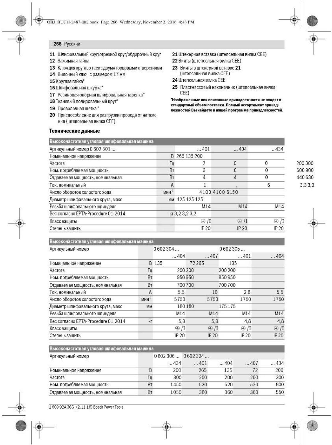
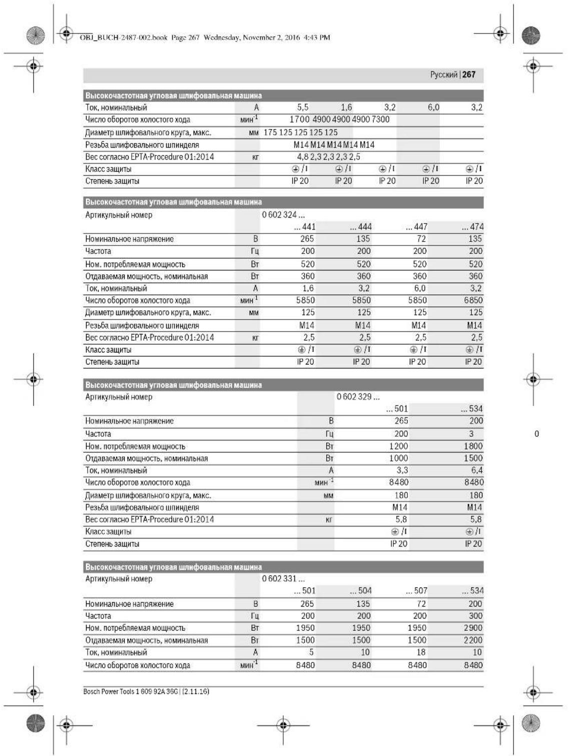
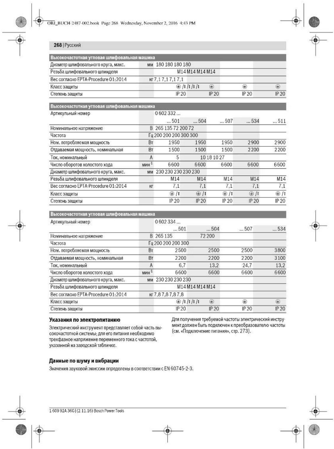
OBI_BUCH-2487-002.book Page 269 Wednesday, November 2, 2016 4:43 PM



| 060230140. | 0602301434. | 060230440. | 060230540. | |
| A-B3BSeHHeHb yPoBeHb IyMa HnCTpy-MeHTa CoCTaJIaRc TnIIuHNoуPoBeHb 3ByKOBIO JIaBHeHnIyPoBeHb 3ByKOBIO MoIaHocTb HeNcOToBepHOCTb KПrHMeHnIte cpeIcTa 3aUHTbOpraHOB cIpya! | ДБ(A) | 72 | 82 | 79 |
| ДБ(A) | 83 | 93 | 90 | |
| ДБ | 3 | 3 | 3 | |
| СуМарна Вибрацьа a₃ (ВeКтог纳суМa ТрEx NaprabIJeHnI) И NOTeIshocTb KОпeДeLEны B COOTbETCTBnCEN60745-2-3. | M/c² | - | 5,3 | 5 |
| M/c² | - | 2 | 2 | |
| ПлИроване: | ||||
| aₙ | M/c² | 3 | 3 | <2,5 |
| K | M/c² | 1,5 | 1,5 | 1,5 |
| ПлИроване дIckOM с abpa3HbHоиIskypkɔi: | ||||
| aₙ | M/c² | 3 | 3 | <2,5 |
| K | M/c² | 1,5 | 1,5 | 1,5 |
| 0 602 306 434 | 0 602 324 40. | 0 602 324 44. | |
| 0 602 324 464 | |||
| 0 602 324 474 | |||
| 0 602 324 434 | |||
| A-BaBSeHHeHb IyPoBeH bIyMa HnCtpymEnHa co- | |||
| cTaubJenTINuHNo | |||
| уPoBeH bIyKobO rO DaBHeHn | d5(A) | 82 | 77 |
| уPoBeH bIyKobO mOuHocTH | d5(A) | 93 | 88 |
| NeJeoCTOBepHOCTb K | d5 | 3 | 3 |
| ПлeMuHneIte cpeDcTaBa aazHtBu opraHOB cnyXa! | |||
| СуМмApHЯ BvIbpaZma a1(bEeTOpHЯ CymMa trpx | |||
| hAnpabLHeHr H nOgpeHIOcTh K onpeHelenb B | |||
| coOTBeTcTBm cEN 60745-2-3. | |||
| ШИнФОВANHe NOBepXHOCTH (оБdИрka): | |||
| a1 | M/c2 | - | - |
| K | M/c2 | - | - |
| ПОЛХОВANHe: | |||
| a1 | M/c2 | <2,5 | 4 |
| K | M/c2 | 1,5 | 1,5 |
| ШИнФОВANHe dIscKOM c aIbpa3HbHo IshkypKoH: | |||
| a1 | M/c2 | <2,5 | 4 |
| K | M/c2 | 1,5 | 1,5 |
| 0.602 329 50. | 0.602 329 534 0.602 329 511 | 0.602 331 5.. | 0.602 332 5.. | |
| A.Бзевений уровец улма Истору МERTA COCTABLANT HINNUCHO урочьberry Boyo Давлиения урочьberry Berry Boyo мошост通风 небочьерноctь K Пrimmenайе среadingва заuntы органов суха! | ДБ(A) | 85 | 87 | 86 |
| ДБ(A) | 96 | 98 | 97 | |
| ДБ | 3 | 3 | 3 |

Bosch Power Tools 1609 92A 36C (2.11.16)


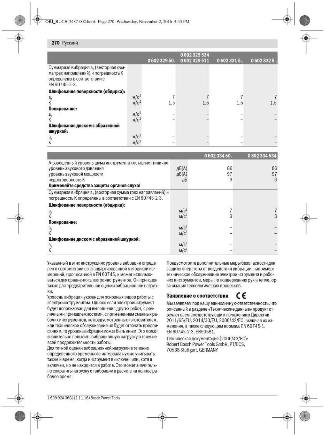

Henk Becker Executive Vice President Engineering
Helmut Heinzelmann Head of Product Certification PT/ECS
y 1x 1 = 2 y 2x 2 = - 4
Robert Bosch Power Tools GmbH 705.38 Stuttgart, GERMANY Stuttgart, 01.01.2017
Russian | 271
Assembly
Installing protective devices
General safety instructions
Before any work on the power tool, pull the plug out of the socket. This precaution prevents unintentional starting of the power tool.
Note: If the protective devices are damaged during operation, have them repaired immediately by an authorized after-sales service center for Bosch power tools. For addresses, see the section "Service and Consulting".
The protective guard must be installed so that it protects the operator from chips in the direction of the operator.
Note: The locking lugs on the protective guards prevent the installation of protective guards not intended for the power tool.
Protective guard for grinding (see figure A) Effective immediately after assembly:
-060230440. -06023295.. -0602324434 -06023315. -060232444. -06023325.. -0602324464 -06023345.. -0602324474
Bend the protective cover around the cutting tool so that the protective cover flange fits against the power tool. Adjust the protective cover position according to the working operation. Lock the protective cover by tightening the screw.
Protective cover
Action following the listed part numbers: -06023044, -06023295, -06023244, -06023215, -06023244, -06023315, -06023314, -06023325, -06023244, -06023235, -06023244, -06023345, -06023244
When cutting with bonded abrasives, always use the protective cover for cutting. Always use the cutting guard with the protective cover for cutting with bonded abrasives (accessory).
The protective cover for cutting is mounted in the same way as the standard protective cover (see figure).
Adjusting the auxiliary handle

Adjusting the handle
The handle can be adjusted to any position to reduce the risk of kickback.
Adjust the auxiliary handle according to the working operation.
Turn the auxiliary handle to the right or left according to the working operation. Do not change the auxiliary handle. Do not use a damaged auxiliary handle.
Action following the listed part numbers:
-06023014, -06023244, -06023054, -06023064
Installation:
First ensure that the thread of the cutting wheel is compatible with the thread of the spindle (M14).
- Make sure that the protective cover and the auxiliary handle are installed (see installation of protective devices, page 271). Screw the cutting wheel onto the spindle by hand, then tighten it with the wrench while holding the spindle with the other wrench.
1609 92A 36G| (2.11.16) Bosch Power Tools


Russian 273
REMOVAL
Unscrew the wire brush from the grinding spindle by gripping the surface with the open-end wrench, while simultaneously holding the spindle with the second open-end wrench on the surface of the grinding spindle.
MOUNTING OF WIRE BRUSHES (see figure H)
Suitable for the following types:
-0 602 304 40. -0 602 331 5..
-0.60232444 464 -0.6023325
474A434 -0.6023345
-0.6023295.
Installation:
Make sure that the wire brush is exactly seated on the thread of the grinding spindle (M14).
Make sure that the installed brush is securely seated and can be operated safely (see installation of safety devices, page 271). Screw the required wire brush (cup or disc) onto the grinding spindle by hand, then tighten it with the open-end wrench on the surface of the grinding spindle, while simultaneously holding the spindle with the second open-end wrench on the surface of the grinding spindle.
REMOVAL
Unscrew the wire brush from the grinding spindle by gripping the surface with the open-end wrench, while simultaneously holding the spindle with the second open-end wrench on the surface of the grinding spindle.
Some types of materials, such as paints with lead content, some types of wood, mineral metals, can be harmful to health. Contact with or inhalation of dust from these materials can cause allergic reactions and/or respiratory diseases in operators or bystanders.
Certain types of dust, e.g., oak and beech wood dust, are carcinogenic, especially when combined with additives for wood treatment (chromate, wood preservatives). Materials containing asbestos may only be handled by specialists.
- If possible, use a vacuum cleaner for material dust. Ensure good ventilation of the work area.
- It is recommended to use a respirator with a P2 filter. Comply with the regulations in your country for the materials being processed.
The extracted dust can spontaneously ignite.
Power supply connection
To connect the electric tool, it must be connected to a frequency converter that provides a three-phase voltage of variable frequency, corresponding to the specifications on the nameplate of the tool.
The frequency converters produced have different powers, different frequencies, different secondary voltages, and different nominal currents. The choice of frequency converter depends on the power of the electric tool. Consult a specialist for the selection of the frequency converter. The electric tool is supplied with a special plug for the socket outlet. Before commissioning the tool, this special plug must be replaced with a standard plug (green color).
In addition, to protect the electric tool from overload, it is necessary to install a common circuit breaker for the electric motor. The current range of this circuit breaker must cover the rated current of the electric tool (see "Technical Data"). The circuit breaker must be installed in the supply line.
Follow the specified safety instructions
Strictly follow the instructions in the operating manual of the motor protection switch.
Installation of the CEE plug (see Fig. 11-12)
Tighten both screws 22, insert the cable gland 21 into the housing of the CEE plug 24. Cut the cable end 25 according to the diameter of the special plug of the electric tool and place the housing of the CEE plug on the special plug. - Route the cable through the cable gland 20 for the connection cable. - Unscrew the four small screws 23 in the cable gland 21 and insert the end of the brown wire L1 into the contact socket L1.
Insert the end of the blue wire L2 into the contact socket L2.
Connect the brown wire to the contact socket L3, and the yellow-green wire to the protective socket.
- Then firmly tighten the two screws 23 in the cable gland 21 to secure these three wires. Then tighten the cable gland nut so that the cable cannot be pulled out of the gland. Insert the cable gland 21 into the opening of the device housing 24 and firmly tighten the two screws 22. Finally, check the protective conductor connection.

274 | Russian
Insert the device plug 24 into the socket of the frequency converter. The frequency converter can now be used to convert the mains voltage. Before commissioning the frequency converter, read the entire operating instructions. Finally, check the direction of rotation. The direction of rotation of the motor must match the arrow shown on the device. If the motor rotates in the wrong direction during initial commissioning (see Switching on the device, p. 274), immediately disconnect the device from the mains.
Then tighten the two screws 22 and insert the cable gland 21 into the housing of the device plug 24.
- Unscrew and remove the end of the brown wire from the contact socket. Insert the end of the yellow-green wire into the contact socket L1, and the end of the brown wire into the contact socket L3.
- Then firmly tighten the two screws 23 in the cable gland 21 to secure the wires. Insert the cable gland 21 into the housing of the device plug 24 and firmly tighten the two screws 22. Finally, check the protective conductor connection. - Connect the device to the electrical system.
Working with the device
Switching on the device
The voltage and frequency of the power source must match the data on the device's rating plate. Check the device for damage before each use. The device must be in perfect condition and rotate freely. Perform a test run for at least 1 minute without load. Do not use damaged devices or devices with cracks or vibrations. Damaged devices can break or cause injury. After switching off, the device may stop unexpectedly during operation; check that the switch is in the off position to prevent unintentional restart. Before restarting the device, check the device (see Maintenance, p. 273).
Always connect the device to the frequency converter first, before connecting the frequency converter to the mains.
Switch on the device only when you are ready to work with it.
Frequency converters are usually started with the power tool switched on. Follow the instructions for use of the frequency converter.
Switching on and off the power tool with a lockable switch (see Fig. J1)
Applicable types: 0 602 324 4
- To switch on the power tool, first press the lockable switch 1 forward. - Lock the switch in the ON position by pressing the lock button. To switch off the power tool, release the switch 1. If the switch is locked, press it briefly and then release it.
Switching on and off the power tool with a lockable switch (see Fig. J2)
Applicable types:
- 0 602 301 4. - 0 602 329 5. - 0 602 304 4. - 0 602 331 5. - 0 602 305 4. - 0 602 332 5. - 0 602 306 4. - 0 602 334 5.
- To switch on the power tool, first press the lockable switch 1 forward and then lock it. - To switch off the power tool, release the switch 1. If it is locked, press it briefly and then release it.
Instructions for use
Before using the tool, check that the accessory is correctly fitted and that the tool is switched off. Observe the safety instructions. Do not operate the tool in explosive atmospheres. Do not overload the tool. Allow the tool to cool down after heavy use before storing it.

Russian 275
Sharpening with a grinding disc
With a grinding disc (accessory) you can also sharpen convex surfaces (sharpening of tools).
Grinding discs are available in various grit sizes, producing a finer or coarser finish. Use the appropriate disc for the desired finish.
Cutting metal (see Fig. K)
Always use the protective guard for cutting off when using bonded abrasives.
Use the cutting wheel suitable for the material being processed. Do not apply excessive pressure to the cutting wheel, do not tilt or jerk it.
Do not use cutting wheels for side grinding.
Always guide the power tool in the direction of rotation. Otherwise, there is a risk of uncontrolled kickback.
Before cutting pipes or cables, make sure there is no voltage in them.
Cutting stone
When cutting stone, ensure sufficient dust extraction and use a dust mask. The power tool is only intended for dry cutting and dry grinding.
It is best to use diamond cutting discs for cutting stone. To protect against tilting, use the protective guard for cutting with guide rails. Work only with the auxiliary handle and use a dust mask. Do not use cutting discs for grinding. The manufacturer offers suitable accessories.
Switch on the power tool and place it with the front part of the guide rail on the workpiece. Guide the power tool with moderate feed, appropriate for the material being processed.
When cutting hard materials, e.g., concrete with a high content of reinforcement, the diamond cutting disc may overheat. A rotating diamond cutting disc with a glowing ring indicates overheating. In this case, interrupt the cutting process and let the diamond cutting disc run at no load speed for a short time. A significant decrease in performance and a glowing ring indicate that the diamond cutting disc is dull. You can resharpen the diamond cutting disc with short cuts in abrasive material (e.g., in silicate brick).
Static specifications
The static specifications of masonry walls are based on DIN 1053 part 1 or the specific regulations of the country in question. The installation instructions must be followed. Before starting work, consult the responsible structural engineer, architect, or site supervisor.
Reverse grinding
Never use cutting discs for reverse grinding!
With the disc at an angle of 30° to 40° to the workpiece, you will get the best results in reverse grinding. Guide the power tool with moderate pressure and back and forth. The workpiece does not heat up much, does not change its color, and no burr remains.
HnHbHaHe HxJdauHoi KypKoHa pe3HOBo onopHOHnnHbHapenke
The choice of grinding disc depends on the material being processed. The company offers a range of grinding discs of various qualities, suitable for the support grinding disc. The product is available in different grit sizes.
Coating with fabric-coated grinding disc
The grinding disc is used for grinding or polishing the surface of the material being processed. During rotation, the abrasive is distributed over the entire surface. Grinding is performed in several passes using the disc. For each pass, the grinding disc is used. If the grit size changes, the grinding disc must be replaced with a different grit size. The surface of the material being processed is prepared before each subsequent pass.
Maintenance and service
Maintenance and cleaning
Before cleaning, remove the tool and disconnect it from the power supply. This measure prevents accidental activation of the tool and ensures safety during cleaning. The tool must always be kept free of dust and debris. In extreme conditions, always use the tool with a residual current device (RCD). When working with materials that produce dust, the tool may become conductive. This can affect the safety of the tool.
276|Russian
Regularly measure the no-load speed of the tool. If the measured value differs from the specified no-load speed by more than 10% (see technical data), the tool must be sent to a Bosch service center for inspection. If the no-load speed is too high, the tool may be damaged, and if it is too low, the working efficiency decreases. Use only original accessories! Before each use of the tool, check the accessories for any damage. If the accessories are damaged, they must be replaced with new ones. The tool should only be serviced by qualified personnel. This ensures the safety of the tool.
Clean the sockets, plugs, and ventilation slots of the tool with a dry cloth that does not shed fibers. Remove dust particles and dirt.
After 150 working hours, clean the gearbox and lubricate it according to the instructions. Use only special gearbox lubricant from Bosch. After cleaning, repeat this procedure every 300 working hours.
The Bosch service center performs this work quickly and reliably.
If the tool is defective, contact Bosch or an authorized service center for power tools.
For safe handling, contact the accessories department.
Accessories
You can download the quality program in the form of a PDF at www.bosch-pt.com and www.boschproductiontools.com, or from your specialized dealer.
Service and consultation on product use
The service workshop will answer all your questions regarding repair and maintenance of your product and spare parts. You can also find spare parts information at:
www.bosch-pt.com
The Bosch team, providing consultation and product use, will gladly answer all your questions regarding our product and its accessories.
Please, in all requests and orders for spare parts, always indicate the 10-digit product number from the type plate.
For Russia, Belarus, Kazakhstan, Ukraine
Proper maintenance and repair of power tools, in accordance with the requirements and norms of the manufacturer, are carried out in all countries only in authorized service centers of Robert Bosch.
WARNING: Use of counterfeit products may lead to health hazards. The manufacture and distribution of counterfeit products is prosecuted administratively and criminally.
Russia
Manufacturer: Bosch Power Tools, 24 Yuzhnoye shosse, 141400 Khimki, Moscow region, Russia. Tel.: 8800 100 8007 (toll-free in Russia) E-Mail: info.powertools@ru.bosch.com You can get current information about the location of service centers and pick-up points: - On the official website www.bosch-pt.ru - By calling the Bosch information and service service 88001008007 (toll-free in Russia)
Belarus
Robert Bosch
Service center for power tool maintenance
ul. Timiryazeva, 65A-020
Belarus
Tel.: +375 (17) 254 78 71
Tel.: +375 (17) 254 79 15/16
Fax: +375 (17) 254 78 75
E-Mail: pt-service.by@bosch.com
Official website: www.bosch-pt.by
Kazakhstan
LLP "Robert Bosch"
Service center for power tools
Almaty
Kazakhstan
050050
pr. Rayymbeka 169/1
st. Kommunalnaya
Tel.: +7(727)2323707
Fax: +7(727)2330787
E-Mail: info.powertools.ka@bosch.com
Official website: www.bosch.kz; www.bosch-pt.kz
Attention
Do not dispose of power tools together with household waste. They must be collected separately for environmentally friendly recycling.
Do not throw power tools into household waste!



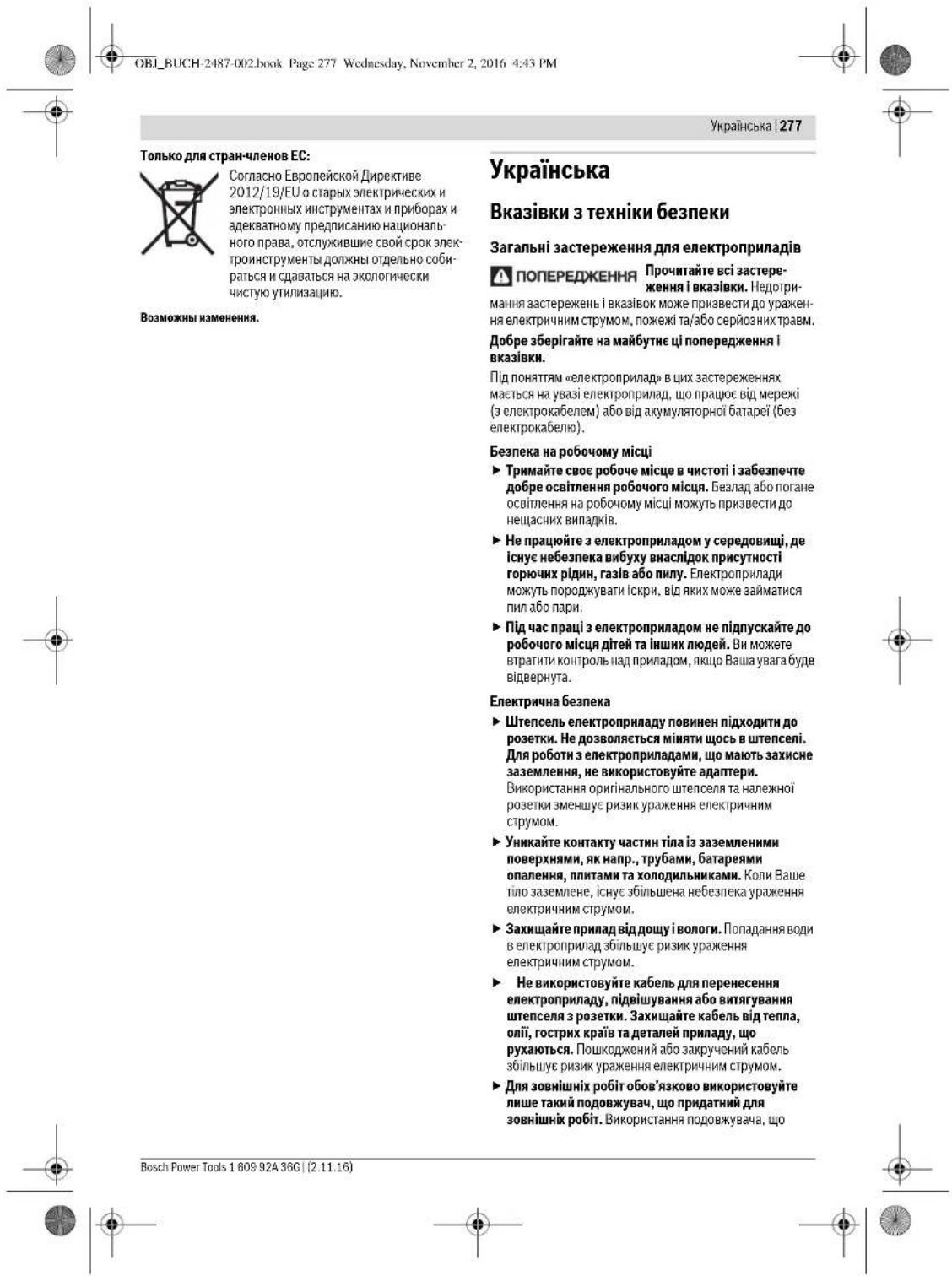
278|Ukrainian
Instructions for use, safety instructions and maintenance for the power tool. If you cannot use the power tool in a damp environment, use a residual current device. Using a residual current device reduces the risk of electric shock. If you cannot use the power tool in a damp environment, use a residual current device. Using a residual current device reduces the risk of electric shock.
Safety
Be careful, follow the instructions, and work thoughtfully during the operation of the power tool. Do not use the power tool if you are tired or under the influence of drugs, alcohol, or medication. A moment of inattention while operating the power tool may result in serious personal injury. Use personal protective equipment. Always wear eye protection. Protective equipment such as a dust mask, non-skid safety shoes, hard hat, or hearing protection used for appropriate conditions will reduce personal injuries. Prevent unintentional starting. Ensure the switch is in the off-position before connecting to a power source and/or battery pack, picking up or carrying the tool. Carrying power tools with your finger on the switch or energizing power tools that have the switch on invites accidents. Remove any adjusting key or wrench before turning the power tool on. A wrench or a key left attached to a rotating part of the power tool may result in personal injury. Do not overreach. Keep proper footing and balance at all times. This enables better control of the power tool in unexpected situations. Dress properly. Do not wear loose clothing or jewelry. Keep your hair, clothing, and gloves away from moving parts. Loose clothes, jewelry, or long hair can be caught in moving parts. If devices are provided for the connection of dust extraction and collection facilities, ensure these are connected and properly used. Use of dust collection can reduce dust-related hazards. Be careful, follow the instructions, and work thoughtfully during the operation of the power tool. Do not use the power tool if you are tired or under the influence of drugs, alcohol, or medication. A moment of inattention while operating the power tool may result in serious personal injury. Use personal protective equipment. Always wear eye protection. Protective equipment such as a dust mask, non-skid safety shoes, hard hat, or hearing protection used for appropriate conditions will reduce personal injuries. Prevent unintentional starting. Ensure the switch is in the off-position before connecting to a power source and/or battery pack, picking up or carrying the tool. Carrying power tools with your finger on the switch or energizing power tools that have the switch on invites accidents. Remove any adjusting key or wrench before turning the power tool on. A wrench or a key left attached to a rotating part of the power tool may result in personal injury. Do not overreach. Keep proper footing and balance at all times. This enables better control of the power tool in unexpected situations. Dress properly. Do not wear loose clothing or jewelry. Keep your hair, clothing, and gloves away from moving parts. Loose clothes, jewelry, or long hair can be caught in moving parts. If devices are provided for the connection of dust extraction and collection facilities, ensure these are connected and properly used. Use of dust collection can reduce dust-related hazards.
Правильне обслуговування електричного приладу
Не перевантажуйте прилад. Використовуйте такі прилади, які призначені для відповідної роботи. З правильним приладом ви з меншим ризиком отримаєте кращі результати роботи, якщо будете працювати в заданому діапазоні потужності.
Не користуйтеся електричним приладом з пошкодженим вимикачем. Електричний прилад, який не можна увімкнути або вимкнути, є небезпечним і потребує ремонту. Перед тим, як регулювати щось на приладі, міняти приладдя або зберігати прилад, вийміть штепсель з розетки та/або вийміть акумуляторну батарею. Ці попереджувальні заходи безпеки зменшують ризик випадкового запуску приладу. Ховайте електричний прилад, яким ви користуєтесь, від дітей. Не дозволяйте користуватися електричним приладом особам, які не знайомі з його роботою або не читали ці вказівки. У разі використання недосвідченими особами прилад може бути небезпечним. Стежте за електричним приладом. Перевірте, що рухомі деталі приладу правильно працюють і не застрягли, не зламані або не пошкоджені, щоб можна було виконувати функціонування електричного приладу. Пошкоджені деталі треба відремонтувати перед їх використанням знову. Багато нещасних випадків стаються через погане обслуговування електричних приладів. Різальні інструменти з гострими краями та в належному стані менш застрягають та легші в експлуатації. Використовуйте електричний прилад, приладдя, робочі інструменти тощо відповідно до цих вказівок. Враховуйте умови роботи та специфіку виконуваної роботи. Використання електричного приладу для робіт, для яких він не призначений, може призвести до небезпечних ситуацій.
Сервіс
Віддавайте прилад на ремонт лише кваліфікованим фахівцям та лише з використанням оригінальних запасних частин. Це забезпечує безпечність приладу.
Вказівки з техніки безпеки для кутових шліфувальних машин
Загальні вказівки з техніки безпеки для шліфувальних машин
Розповсюджується на наступні типи:
Правильне обслуговування електричного приладу
Не перевантажуйте прилад. Використовуйте такі прилади, які призначені для відповідної роботи. З правильним приладом ви з меншим ризиком отримаєте кращі результати роботи, якщо будете працювати в заданому діапазоні потужності.
280|Українська
Регулювання вентиляції внутрішнього електричного приладу. Вентилятор електродвигуна розташований у корпусі, сильне накопичення матеріалу може призвести до електричної небезпеки. Не користуйтеся електричним приладом поблизу горючих матеріалів. Такі матеріали можуть займатися від іскор. Не використовуйте інструменти, що потребують охолоджувальної рідини. Використання води або іншої охолоджувальної рідини може призвести до ураження електричним струмом.
Сигнали та відповідні попередження
The machine is not designed for use on a grinding wheel or a cutting wheel, or a wire brush. As a result, the power tool may not be properly controlled when using a grinding wheel or a wire brush. If the grinding wheel or wire brush gets caught in the material, it may cause the tool to kick back. In the event of a kickback, the grinding wheel may move in the opposite direction of the wheel's rotation at the point of entanglement. The grinding wheel may also break. This is not the result of improper operation, but rather a result of misuse. You can avoid this by taking the proper precautions described below. Hold the power tool firmly with both hands and position your body so that you can resist the kickback forces. Always use the auxiliary handle (if provided) to have maximum control over the tool during startup and to be able to counteract the kickback and reactive torque forces. You can counteract the kickback and reactive torque forces by taking proper precautions. Never place your hand near the rotating accessory, as the accessory may kick back over your hand. If kickback occurs, the tool may be thrown in the direction opposite to the rotation of the accessory at the point of entanglement. The tool may also be thrown if the accessory binds. The tool is designed to be used with the correct type of accessory and guard. The guard must be properly attached to the tool and positioned for maximum safety, so that the least amount of the accessory is exposed to the operator. The guard helps to protect the operator from broken accessory fragments and accidental contact with the accessory. The accessory must be rated for at least the speed recommended on the tool's nameplate. Accessories rated for a higher speed may fly apart. The outside diameter and thickness of the accessory must be within the capacity rating of your power tool. Incorrectly sized accessories cannot be adequately guarded or controlled. The arbor size of wheels, flanges, backing pads, or any other accessory must properly fit the spindle of the power tool. Accessories with arbor holes that do not match the mounting hardware of the power tool will run out of balance, vibrate excessively, and may cause loss of control. Do not use damaged accessories. Before each use, inspect the accessory such as abrasive wheels for chips and cracks, backing pad for cracks, tear or excess wear, wire brush for loose or cracked wires. If the power tool or accessory is dropped, inspect for damage or install an undamaged accessory. After inspecting and installing an accessory, position yourself and bystanders away from the plane of the rotating accessory and run the power tool at maximum no-load speed for one minute. Damaged accessories will normally break apart during this test time. Wear personal protective equipment. Depending on application, use face shield, safety goggles or safety glasses. As appropriate, wear dust mask, hearing protectors, gloves and workshop apron capable of stopping small abrasive or workpiece fragments. The eye protection must be capable of stopping flying debris generated by various operations. The dust mask or respirator must be capable of filtrating particles generated by your operation. Prolonged exposure to high intensity noise may cause hearing loss. Keep bystanders a safe distance away from work area. Anyone entering the work area must wear personal protective equipment. Fragments of workpiece or of a broken accessory may fly away and cause injury beyond immediate area of operation. Hold the power tool by insulated gripping surfaces only, when performing an operation where the cutting accessory may contact hidden wiring or its own cord. Contact with a "live" wire will also make exposed metal parts of the power tool "live" and shock the operator. Always use the auxiliary handle, if provided, for maximum control over kickback or torque reaction during start-up. The operator can control torque reactions or kickback forces, if proper precautions are taken. Never place your hand near the rotating accessory, as the accessory may kick back over your hand. Do not position your body in the area where the power tool will move if kickback occurs. Kickback will propel the tool in direction opposite to the wheel's movement at the point of snagging. Use special care when working corners, sharp edges etc. to avoid snagging and catching of the accessory. Do not attach a saw chain woodcarving blade or toothed saw blade. Such blades create frequent kickback and loss of control. Do not use any accessory that requires liquid coolants. Using water or other liquid coolants may result in electrocution or shock. When using the tool, always hold it firmly with both hands and position your body to resist the kickback forces. The auxiliary handle, if provided, will give you maximum control. Always use the correct type of guard for the accessory being used. The guard must be properly attached to the tool and positioned for maximum safety, so the least amount of the accessory is exposed to the operator. The guard helps to protect the operator from broken accessory fragments and accidental contact with the accessory. The accessory must be rated for at least the speed recommended on the tool's nameplate. Accessories rated for a higher speed may fly apart. The outside diameter and thickness of the accessory must be within the capacity rating of your power tool. Incorrectly sized accessories cannot be adequately guarded or controlled. The arbor size of wheels, flanges, backing pads, or any other accessory must properly fit the spindle of the power tool. Accessories with arbor holes that do not match the mounting hardware of the power tool will run out of balance, vibrate excessively, and may cause loss of control. Do not use damaged accessories. Before each use, inspect the accessory such as abrasive wheels for chips and cracks, backing pad for cracks, tear or excess wear, wire brush for loose or cracked wires. If the power tool or accessory is dropped, inspect for damage or install an undamaged accessory. After inspecting and installing an accessory, position yourself and bystanders away from the plane of the rotating accessory and run the power tool at maximum no-load speed for one minute. Damaged accessories will normally break apart during this test time. Wear personal protective equipment. Depending on application, use face shield, safety goggles or safety glasses. As appropriate, wear dust mask, hearing protectors, gloves and workshop apron capable of stopping small abrasive or workpiece fragments. The eye protection must be capable of stopping flying debris generated by various operations. The dust mask or respirator must be capable of filtrating particles generated by your operation. Prolonged exposure to high intensity noise may cause hearing loss. Keep bystanders a safe distance away from work area. Anyone entering the work area must wear personal protective equipment. Fragments of workpiece or of a broken accessory may fly away and cause injury beyond immediate area of operation. Hold the power tool by insulated gripping surfaces only, when performing an operation where the cutting accessory may contact hidden wiring or its own cord. Contact with a "live" wire will also make exposed metal parts of the power tool "live" and shock the operator. Always use the auxiliary handle, if provided, for maximum control over kickback or torque reaction during start-up. The operator can control torque reactions or kickback forces, if proper precautions are taken. Never place your hand near the rotating accessory, as the accessory may kick back over your hand. Do not position your body in the area where the power tool will move if kickback occurs. Kickback will propel the tool in direction opposite to the wheel's movement at the point of snagging. Use special care when working corners, sharp edges etc. to avoid snagging and catching of the accessory. Do not attach a saw chain woodcarving blade or toothed saw blade. Such blades create frequent kickback and loss of control. Do not use any accessory that requires liquid coolants. Using water or other liquid coolants may result in electrocution or shock.
Do not use worn-out grinding wheels or wheels with cracks. Such tools often cause injuries and are dangerous to operate. Always wear protective goggles when using or repairing the wheel, intended for your electric tool, and install the guard that is provided for the grinding wheel. A grinding wheel that is not provided for repair cannot be sufficiently securely attached, therefore they are dangerous. The protruding grinding wheel must be mounted such that the working surface protrudes beyond the edge of the protective guard. An incorrectly mounted grinding wheel that protrudes beyond the edge of the protective guard is not sufficiently protected. The protective guard must be installed on the electric tool and adjusted so that the maximum exposed part of the grinding wheel faces the operator as little as possible. The protective guard protects the operator from fragments of the grinding wheel and from accidental contact with the grinding tool. The grinding wheel must be used only for recommended applications. Never use the side of the grinding wheel for cutting. Cutting wheels are intended for cutting the material of the grinding wheel. They can break the grinding wheel. Always use a new, undamaged grinding wheel of the appropriate size and shape. Replace the grinding wheel if it is damaged, as this may cause imbalance of the grinding wheel. The edges of cutting wheels must be used for cutting only. Do not use damaged grinding wheels that are larger than the electric tool's rated size. Grinding wheels for larger electric tools are designed for higher speeds and may break.
Always wear protective goggles when cutting with grinding wheels.
Always hold the tool with both hands, in front of and behind the wheel. Move the cutting wheel in the material in the direction away from you, so that if the electric tool with the wheel kicks back, it can jump directly at you.


Turn the tool slowly, gradually increasing the speed, and keep it steady until the tool stops. Do not attempt to make cuts in one pass, as this may cause the tool to bind, overheat, or break. Do not use the power tool until you have filled the material. Give the tool time to reach full speed before you begin the cut. Otherwise, the tool may jam, and the material may be thrown. Keep the tool away from the material surface, and guide the tool smoothly. The material surface may be damaged. The material must be cut from both sides, and then from the edge. Be careful when cutting in tight spaces or corners, where the tool may jam. A jammed tool can cause a kickback, and the power cord may be damaged.
Special precautions when working with the tool
Do not use a dull blade. Follow the instructions to sharpen the blade. A dull blade that extends beyond the guard can cause injury, and a broken blade can lead to accidents.
Special precautions when working with the guard, especially the blade guard. Keep the guard closed. A loose guard that rotates with the blade can cut your fingers or get caught in the material.
Special precautions when working with the tool
Be aware that the tool may kick back if the blade is not sharp. Do not force the tool. Let the tool do the work. A dull blade can easily bind in the cut or kick back. Keep the guard closed and ensure that the guard and the blade are aligned. The blade guard may be damaged if the tool is used improperly.
Additional precautions
Wear safety goggles!
Connect the tool to a socket outlet or extension cord with a protective earth conductor. Before use, check with a specialist that the electrical, gas, and water supply lines are properly grounded. The protective earth conductor must be connected to the ground terminal and protected against electric shock. The gas pipe must be connected to the ground. The connection to the water pipe may cause material damage or lead to electric shock. When using electrical appliances, if there are voltage fluctuations or if the plug is pulled out of the socket, unplug and plug it back in. This way you will prevent uncontrolled switching on of the device. Do not touch the power cord with wet hands, it may not be safe. The power cord must be kept away from heat sources. When working with the device, keep your hands dry to avoid electric shock. With dry hands you can safely operate the electrical appliance. Close the protective cover. With the help of the locking device, the protective cover can be secured when the tool is not in use. Unplug the electrical appliance from the mains, ensuring reliable grounding. The socket and the connected cable must be in proper condition.
Safety instructions for working with high-frequency tools
Strictly follow the safety instructions for the tool, as they relate to the specific device! Detailed information can be obtained from the manufacturer of the specific device. It is important to note that the tool must be switched off automatically if the frequency exceeds the limit. Special attention should be paid to the supply voltage, the protective conductor, and the grounding of the device. The automatic shutdown may be triggered by materials that can conduct electricity. Failure to observe the automatic shutdown may lead to electric shock, damage to the device, or injury. The automatic shutdown must only be installed by specialists. Only in this way can the safe operation of the tool be ensured. The frequency of the tool must be checked regularly. The tool can be operated without the automatic shutdown. The automatic shutdown must be calculated for the nominal current required by the tool (see technical data).




OBI_BUCH-2487-002.book Page 282 Wednesday, November 2, 2016 4:43 PM
282|Ukrainian
The use of the tool and its maintenance must be carried out by qualified personnel who have been trained in working with high-frequency tools. Use only original accessories! Before each use, check the tool for damage. The tool must not be repaired by the user; repairs must be carried out by qualified personnel. Damaged parts must be replaced.
OBI_BUCH-2487-002.book Page 285 Wednesday, November 2, 2016 4:43 PM
Ukrainian 285
| Ви这样做 не一定会帮您顺利通过考试吗? | |||||
| Bara iadinovidno do EPTA-Procedure 01:2014 | кг 7,17,17,17,17,1 | ||||
| Клас зхасу | ©/I | ©/I | ©/I | ©/I | ©/I |
| Стейнь зхасу | IP 20 | IP 20 | IP 20 | IP 20 | IP 20 |
High-frequency tool
| Aptнкуншим Homep | 0 602 334 ... | ||||
| ... 501 | ... 504 | ... 507 | ... 534 | ||
| Hom. Hanpyra | B 265 135 72 200 | ||||
| Частora | ГИ 200 200 200 300 | ||||
| Hom. сponжва на поожи绩ь | Вт 2500 2500 2500 3800 | ||||
| Hominaльна виндна поожи绩ь | Вт 2200 2200 2200 3100 | ||||
| Hominaльный скум | A 6,7 13,2 24,7 13,2 | ||||
| Кільские оберп в hoхлостому xody | xви.1 | 6600 6600 6600 6600 | |||
| Мас. дiamетршифыевно круga | MM 230 230 230 230 | ||||
| Рлбашадуалныогошения | M14 M14 M14 M14 | ||||
| Bara bīdnoviho do EPTA Procedure 01:2014 | кг 7,8 7,8 7,8 7,8 | ||||
| Клас зхису | ©/I | ©/I | ©/I | ©/I | |
| Стуриль зхису | IP 20 | IP 20 | IP 20 | IP 20 |
Operating instructions
The tool is designed for high-frequency systems and requires a power supply with the appropriate frequency, as indicated on the nameplate.
The tool must be operated with a frequency converter (see "Frequency converter", page 290).
Information on vibration
The vibration emission value was measured in accordance with EN 60745-2-3.
OBI_BUCH-2487-002.book Page 287 Wednesday, November 2, 2016 4:43 PM
Declaration of Conformity (2006/42/EC): Robert Bosch Power Tools GmbH, PT/EC5, 70538 Stuttgart, GERMANY
Henk Becker Helmut Heinzelmann Executive Vice President Head of Product Certification Engineering PT/ECS

Robert Bosch Power Tools GmbH 70538 Stuttgart, GERMANY Stuttgart, 01.01.2017
MOUNTING
MOUNTING Protective Devices
Important instructions
Before any work on the power tool (e.g., maintenance, tool change, etc.), remove the power tool from the power supply. If the power tool is accidentally started, there is a risk of injury.
Warning: To reduce the risk of injury, when working with the power tool or when changing protective devices, the power tool must be switched off and disconnected from the power supply. Have the power tool serviced by a qualified repairman using only identical replacement parts. This will ensure that the safety of the power tool is maintained.
The protective guard must be installed so that sparks cannot fly towards the operator.
Warning: Due to the rotating grinding wheel on the power tool, it is only allowed to mount the protective guard in the correct position.
Protective guard for grinding
The following types are available:
- 0 602 304 40. - 0 602 329 5.. - 0 602 324 43 4 - 0 602 331 5.. - 0 602 324 44. - 0 602 332 5.. - 0 602 324 46 4 - 0 602 334 5. - 0 602 324 47 4 Install the protective guard with the clamping screw so that the guard is firmly attached to the power tool. Mount the protective guard so that it is positioned correctly for the intended application - the closed side of the guard must face the operator.
Protective guard for cutting
Po3noBcIOxkyCTbCHaHAcTyNHiTnN:
-060230440. -06023295.. -0.602324434 -0.6023315 -0.602324.44 -0.6023325 -0.602324464 0.6023345 -0602324474
Bosch Power Tools 1609 92A 36C (2.11.16)




OBI_BUCH-2487-002.book Page 288 Wednesday, November 2, 2016 4:43 PM
288|Ukrainian
For cutting with the connected abrasive, it is necessary to cover the cutting disc with a special protective guard. When cutting, always use the protective guard for cutting with the connected abrasive.
The protective guard for cutting must be mounted in accordance with the standard protective guard (DMB, AN).
Auxiliary handle (see figure B)
Auxiliary handle
Turn the auxiliary handle to ensure a safe grip.
OBI_BUCH-2487-002.book Page 289 Wednesday, November 2, 2016 4:43 PM
Ukrainian 289
Mount the cutting tool (see figure D). Mounting the cutting, roughing, or flap discs, see page 288. Pull the spindle lock and tighten the cutting disc.
Mounting the rubber backing pad (see figure F)
Po3noBcIOxkyCTbCHaHAcTyNHTHIN:
-06023014. -060232440 -060230540.
-0602306434
MOUNTING
Insert, when installing the handle, the installation (see mounting of the locking device, p.207). Install the thrust washer 17 on the thrust pin of the spindle. - Then install the thrust washer 16 on the rubber thrust pin. Install the thrust washer 15 on the spindle. - Turn the thrust washer with the socket wrench 13 two turns, holding it with the socket wrench 14 while turning the spindle with the other key.
Make sure that the washer 15 is fully seated in the groove of the thrust pin, so that it does not fall out during turning and the turning of the washer is not hindered.
Demounting
Hold the spindle with the socket wrench 14 on the surface of the key. Turn the washer 15 with the socket wrench 13 two turns and remove it from the spindle, holding it with the socket wrench 14 on the surface of the key. - Remove the thrust washer 16 and the thrust pin of the spindle.
Mounting of the thrust washer (see Fig. 7)
Proceed as follows:
-06023014. -060232440 -060230540. -0602306434
Mounting
Make sure that the thrust washer is correctly seated on the spindle (M14).
Insert, when installing the handle, the installation (see mounting of the locking device, p.287). Screw the thrust washer 18 onto the spindle by hand, so that the flat surface is against the key of the spindle; then hold it with the socket wrench 14 on the surface of the key of the spindle.
Demounting
Remove the thrust washer 18, if it is too tight on the spindle, by holding it with the socket wrench on the surface of the key, and turning it with the socket wrench 14 on the surface of the key of the spindle.
Such materials, e.g., coatings, lead, hard wood, minerals and metals, can be hazardous. Touching them or inhaling their dust can cause poisoning, allergic reactions or diseases. Therefore, when working with such materials, it is necessary to use personal protective equipment (respirators, protective gloves) and to ensure good ventilation of the workplace. Follow the recommendations of the tool manufacturer. It is recommended to use a respirator with a P2 filter.
Dispose of used materials in an environmentally friendly manner.
Avoid contact with eyes. If it gets in, rinse immediately.

Recommended for use with a residual current device.
The power tool must be connected to a power supply with a voltage corresponding to the value indicated on the nameplate.
The power tool is designed for various applications with different speeds and torques. The selection of the power tool depends on the type of work. For the correct selection of the power tool, consult a specialist at a specialized Bosch service center.
The power tool is supplied with a mains cable without a plug. To connect the power tool, a plug must be mounted on the special cable by a qualified electrician (see markings).
When using the power tool outdoors, a residual current device (RCD) can be installed. The RCD must comply with the rated current of the power tool (see "Technical Data"). The RCD must trip within at least one second. Also, follow the safety instructions and the operating instructions for the RCD!
Mounting the plug (see figures 11-12)
Remove the cover 22 and the plug insert 23 from the housing of the plug 24. - Press the cable gland 25 onto the cable of the power tool and screw the housing of the plug 24 onto the special cable. - Pull the cable through the strain relief 2 and the plug insert 21. Insert the brown cable core L1 into the contact R1, the blue cable core L2 into the contact R2, the green-yellow cable core # into the contact for the protective conductor. Tighten the screws 23 of the plug insert 21. To avoid strain on the cable, tighten the strain relief 20 around the cable. Insert the plug insert 21 into the housing of the plug 24 and tighten the screws 22. - Check the correct connection of the protective conductor. The plug is now ready for connection to the power supply.
Before starting work, read the instruction manual carefully.
The information provided in this manual has been translated from the original source and the operating instructions have been translated as well.
After this, check the direction of rotation!
Checking the direction of rotation
The frequency converter must be connected to the mains via a protective device. The protective device must be sized according to the rated current (see Electrical connection, page 291). Connect the protective conductor to the protective terminal, then connect the electrical supply and the load to the corresponding terminals. Then insert the two protective caps 21 into the cable glands CEE 24. Check the correct installation of the protective caps. 3. Connect the electrical supply to the source of supply.
Operation
Starting the machine
The voltage and frequency of the supply source must correspond to the data in the table of the electrical instrument. Check the manual of the instrument before switching on. The instrument must be properly grounded and completely turned off. Do not use a damaged or twisted manual instrument or one that is visibly worn. A damaged manual instrument can cause serious injury or damage when switching on the electrical instrument. To start the work, switch on the switch. In this way, the electrical instrument is supplied with voltage. Before switching on the electrical instrument, check the supply parameters (see Connection of the supply source, page 290). Start the electrical instrument by pressing the switch, then release the switch.
With a grounded supply, switch on the electrical instrument only when you intend to use it.


OBI_BUCH-2487-002.book Page 291 Wednesday, November 2, 2016 4:43 PM
Ukrainian 291
Switching on/off the frequency converter
Press the required switch to switch on the electrical instrument.
Press the switch to switch off the electrical instrument.
Switching on/off the electrical supply
i33a06ixHHM NOB3yHKOBHM BHMNaayem (nHb.MaJ.J1)
P03OBOCIOXyETbCa HACNTNI TINH: -0602324.
-Ⅲo8yIbIMKhyn eIeKToPnpHnA,IocYhTe BIMHKa1 1 Ynepd. Li063a4bckyBnHMMKNa1, HATCHiTb HAMMKNa 1 Cnepdy, 060 Bih 3actonDBNC. -1106BHHKHYENeKTPOHCTPymeT,BIDNYCITb BHHMKAA 1.
Yp3a1dijkocboharo BHHMKAa1 HATCHiBb KOPOTKO 334yyu B HAMKAAI bI iDIIyCITb ITOHO.
BMnKaHHBmKnKaHHeneKTponpHnady
OBI_BUCH-2487-002.book Page 295 Wednesday, November 2, 2016 4:43 PM
Kasaika 295
3aKbMdMaHaB GonybHa, 3eKtp KypanbHbH 3akMbMaHaRaBHn Ke3 XekTl3i3J3. 3akmDlanr HbnweKepi6apKpynabNnAanadanyanBnKeHeknE3. 3eKtp KypanabPiHbNpybc KyTinMey iKaataaBIM OKhAnapra ceben BonBnKatDa
Kekkiu ancapantpu 1ktrip kxea ta3a kyeane kaTahnla. Ⅲpybckyrinren hxe Keckiu jxmeKTepre 1ktpke Kekkiu acanapnt aKeTrenin, kceiTeBtke OhaJ BarbTTaunda. 3NeKtp KpyaBn, Xa6bIkTapRb, amanBn-camMaBn acnantapBxJXeT1.6.OcbIyHcyAynapRa cai naHdAnBaHbNc. CoHNm JYMbIC uapTApBmE opHdAnBn apKeETpe Ra3ap ayDpaHbN3.3NeKtp KpyaBpH apHaMfAah XMyBCTapPa naDanaHy kayiInI.
Kb3MeT
3Nektp KypalbHn3dI Tek 6nKiTmAMAHaFxaHe apaybIb6bnKTepeMxKoetHcIa. Cn apkblb3 Nektp KypalbHn3KayinciDrii cakTaiBla.
BpybIbIK tericTey MaunHnapbH naaDanany KeiHeriKayinci3dkTexnKacbl
Ereykay karaabemih bckbnaydarb kbltbpatydarbXannabiKayincikn Hyckaynapa
TomehderiytpnpywnTnicti:
-06023014. -060230540 -0602306434 -060232440.
This electric crane is designed for lifting and moving loads in various industries. Large and heavy loads, equipment, and materials can be moved safely. The crane control panel provides reliable operation, and if necessary, it can be used for lifting and moving loads. This crane is equipped with safety devices to prevent overloading and to ensure safe operation.
The control panel, lifting mechanism, and safety devices are equipped with the following components:
-060230440 -060232444,..464,..474,..434 -06023295.. -06023315. -06023325. -06023345.
This electric crane is designed for lifting and moving loads using a remote control. Large and heavy loads, equipment, and materials can be moved safely. The crane control panel provides reliable operation, and if necessary, it can be used for lifting and moving loads.
This crane is equipped with safety devices to prevent overloading and to ensure safe operation. The crane's safety devices are designed to prevent overloading and to ensure safe operation.
During operation, lifting, moving, and lowering loads, the safety devices must be in proper working condition. The following are the main components of the safety devices.
OcbI3eKtp KypaBbHa apHannmarr HKeHe
EhDpyuimEH CbyHBnMarrA HxabDbkTapdbi
naidanah6b3.3.3eKtp KypaBbHa 6epik 6ekyI
MymxHirB iBap KaaBbKtap Fana Kayinci naiJauanydu
kAMTamac3 eTejI
Anmblcannblacnblhpykcatetiren aHahmbdnapcaHkeHneKTPKpaanbHa daBenrtnehMaKcmnblaHahnbmdapcaHbna coKeec 60bnpek. PyKcatetireHHeHHJbAm anHahatbHka6dbk63bHIn,waBbHInKcyiMyMKH
XMyBc KpAaBnHb CbIptKbIaMometPjKe H KbnIbIbIe IneKp KpAaBnOuMepe DcAke GonybKepe. Ooemepi Kate anhktanr hCanBHraH Benweek XkettKlkiK pKprAnMaHbjxKe HgKaInaydah bMyfby MyMYIKH.
Hpeokimabtecikepi bap teritey uehbpnepi teritey uinnndinihn. hpeokimabha daan kenyi kenek. fnaeneu cemiremen opahbtaunk ypaandpabi nainanaanraa kypantecirihin damaetpi fnaaneu dhametpihe cainkec keniy kepek. 3nkp kypanda Dyobic Tpymaar anxmybc kypandaabo corbnibn aHaana, KaTb npindni jkae6aknaydbkotanyra aknyi Mymkh.
By3bHnAnAmnAn-canmAn acnantbl nainanahabib.3Xmbc Kypanapabihna,mbicn, terietey uhebpeneriue,epa nainanay anbnhda cbnbkTap xane kapbKTap,terietey tapenkepeHne cbhItap,etnc6bnny kany XeKtne TaTOy 6apKboHH,cbMbIu eTkanpada 6eKtiinemer en Xe HcHraH cbmbdap 6ap-oxBoH Teckepi3.3NeKtp KypanBH HEmecE Anmblc-anCanmbl acnantbl Tycipin anCahbs,OnbTeckepi3,Tek3akmbdmanafan Anmblc-anCanmbl acnantbl NainanahbH3.Anmblc-anCanmbl acnantbl Teckepin nainanany Ke3iHe 03i3dn XeOe 3e T aanadpanbH anHaatah anMnblc-anCanmbl acnantbl KaubkJxpe deTypranbHa rana 3NeKtp KypanbHbip MNHT iHHe MAcmmbl aaihbnbmdap cAnhda KocbHb3. 3AkmbdHanAnmblc-anCanmbl acnantap ocb teKcepy Ke3HHe 6by3nabl.
XKeKoPFAHbIC XAbdbkTApBn KInN JypiH3.
XMybCTa 6ETTI TOnBk KpOAFthm Mackahbl, Ke3
CaTAYbIbIc KEmeCOPFAHbIK Ke3INDipkiT KInH3.
KaKet Bocca WAnTyKbIbI, KopFaybIbIK KonrAtnbl,
AnKanKbIbIbI HEmeCe BaKaopFBAKbcHMnepin
KInH3. Ko3dep aTpyPi XymbCTaPdAn naJa Bonbl
waBunlbn 6TeH 6BnWKeTppeHn KpOraHy bKaJET.
UAnTyKbIbIK HeR aR3karap Xymbc Ke3IeNa daJa
Bonatbl WAnBbY cy3iEe Ie3JI. DaBbCb KaTbl
yybnda kon Bojly eCy KabinEni IeMeHETy MyMknH.

296|Kasaika
Before starting any work, carefully read the instructions. The instructions contain important safety information. If the instructions are not followed, the device may be used incorrectly, which could lead to injury or damage. Keep the instructions for future reference. If the device is passed on to another user, the instructions must be handed over with it. The device is intended for use in accordance with the instructions. Use only as described in the instructions. The device is not a toy. Keep it away from children. Do not use the device if it is damaged or malfunctioning. If the device is damaged, have it repaired by a qualified person. Use only original spare parts. The device must be operated with the correct voltage. Check the voltage before connecting the device. The device must be grounded. Do not use the device in wet conditions. Keep the device dry. Do not use the device near flammable materials. The device may cause interference with other electronic devices. Keep the device away from sources of heat. The device must be cleaned regularly. Use a dry cloth to clean the device. Do not use solvents or abrasive cleaners.
Before first use, check the device for damage.
If the device is damaged, do not use it. Contact a qualified person to repair it. Do not attempt to repair the device yourself. If the device is not working properly, check the power supply and the connection. If the device still does not work, contact the manufacturer or a qualified service center.
If the device is not working properly, check the power supply and the connection. If the device still does not work, contact the manufacturer or a qualified service center. Do not open the device. There are no user-serviceable parts inside. Refer all servicing to qualified personnel.
Dispose of the device in accordance with local regulations.
The crane must be installed on a foundation that can withstand the loads from the crane's operation. The foundation must be designed to handle the maximum loads that may occur during operation, including wind loads. The crane operator must be trained and certified to operate the crane safely. The crane must be inspected regularly to ensure it is in good working condition. The crane's electrical system must be properly grounded and protected against short circuits. The crane must be equipped with safety devices such as limit switches and overload protection. The crane's load capacity must not be exceeded. The crane must be operated by a qualified operator who has been trained in the safe operation of the crane. The crane must be maintained in accordance with the manufacturer's instructions. The crane must be inspected before each use to ensure it is in safe working condition. The crane must be operated in accordance with the manufacturer's instructions and all applicable safety regulations.
The device is intended for use in the livestock industry. It can be used for both cattle and small ruminants. The device must be handled with care to avoid damage. It is possible to use the device for veterinary purposes. The device should be kept clean and dry. It is recommended to use the device only for its intended purpose. The device is not intended for use in explosive atmospheres. The device should be stored in a cool, dry place. The device should be protected from moisture and dust. The device should be cleaned with a soft, dry cloth. Do not use harsh chemicals or solvents. The device should be checked regularly for signs of wear and tear. If the device is damaged, it should be repaired by a qualified technician. The device should be used in accordance with the manufacturer's instructions. The device should be kept out of reach of children. The device should be disposed of in accordance with local regulations.



The device is not intended for use in explosive atmospheres. It is possible to use the device for veterinary purposes.
Electric shock hazard. Before connecting to the electric network, it is necessary to take measures to prevent electric shock. The test equipment must be connected to a grounded electrical outlet. Do not use extension cords or adapters. If the equipment is used in a manner not specified by the manufacturer, the protection provided by the equipment may be impaired. To avoid electric shock, do not open the equipment. Refer all servicing to qualified personnel. The equipment is intended for indoor use only. Do not expose it to rain or moisture. If the equipment is not used for a long time, disconnect it from the power source. When connecting the equipment to the power supply, ensure that the voltage matches the rating. If the power cord is damaged, replace it with a new one. Do not operate the equipment with a damaged cord. If the equipment emits smoke or a burning smell, turn it off immediately and unplug it. Contact qualified service personnel.
Instructions for safe use of the equipment in accordance with the technical description.
Before starting work, read the instructions carefully. If the instructions are not followed, the equipment may be damaged, and the manufacturer is not responsible for any resulting damage.
Instructions for safe operation of the equipment during maintenance.
Do not operate the equipment without proper grounding. Ensure that the grounding conductor is connected first. If the grounding is not connected, there is a risk of electric shock.
Cleaning instructions for the equipment (brush).
When cleaning the equipment, ensure that it is unplugged. Do not use liquid cleaners or sprays. Use a dry cloth to clean the equipment.
Do not use the equipment in the presence of flammable gases or vapors. Keep the equipment away from heat sources and open flames.
The equipment must be used only for its intended purpose.

Kazakhstan Temir Zholy, JSC, Astana, r3a, 3neKtp cbimdpabn TabbHb3 HEMECExepriNtki KbiMeT KepeCyYbIMdpabn uakpbmb3. 3NeKTP cBmdpabHaTHIO ePT HEMeC TOK coryiba anbin KenyI MymKH. Ia3 KybipbH 3akbIMday baibcikca anbin KenyI MymKH. CyKybpbHa THIO MaterpaHAnDkb3HH HEMeCE ToK CORYBaA anbin KenyI MMyKH. Kyatoece,mbicanb,kenide Kyaatok Gonbln Kanca Hemece aaihba potezradan cybpfaanda cndipriu Gedtkiin anbIb3 xane eupinyi Kyne opahtbhl3. Byn apkbln keeiencoKocbynbnmdu. Teretichy Xeoh Kecy uehEpneiphi TmeHJI. UeHepner YXMBcK3J1He Kb3a2dN. 3NeKtp KpyaBnI naDAnanyda Obl Eki KonmH 6epix yctan, TypaKbI KaNbIra TpybHb3.3NeKtp KpyaBnE KI konMeh CenHMI backapunBan. AaHnDamaHb6ekit3. Kbcy KpaIbHaHEmece KckBkaOpahtBuHaDaHbHnDamaKoIbIb6eH anCbIcIbPrHaDb,bePik YctanAb. 3NeKtp KypanbH TnichrtaptInnen Jxpe RokcbunrAton KxcineKocbHb3. PoTeRaMe YJ3apKbIaTa XyMbIc ICTINTH KOPARB HCBM 60Nby KXKT.
KofapbI xinnik acnantapdbI 3HeprnmaHem Ka6DbkTay yuin Kayinc3dk HycKaynnapbI
Kayinlciaik nen xmybc Hcykaynabxnnik tynpndpiuiuynmuknyeckepin3!On typanbokcbmaMaImimetreppdi nnkinr TpyneHdpriuiHHDipuyicHehAnacb3. XinHK tyPnHDPriiHn KAteApAraHbN ToK koprayBiyMmienKayincIaDnHpyKepe,erep aadamapd apnaih perte Kopray Kepek BonFaH

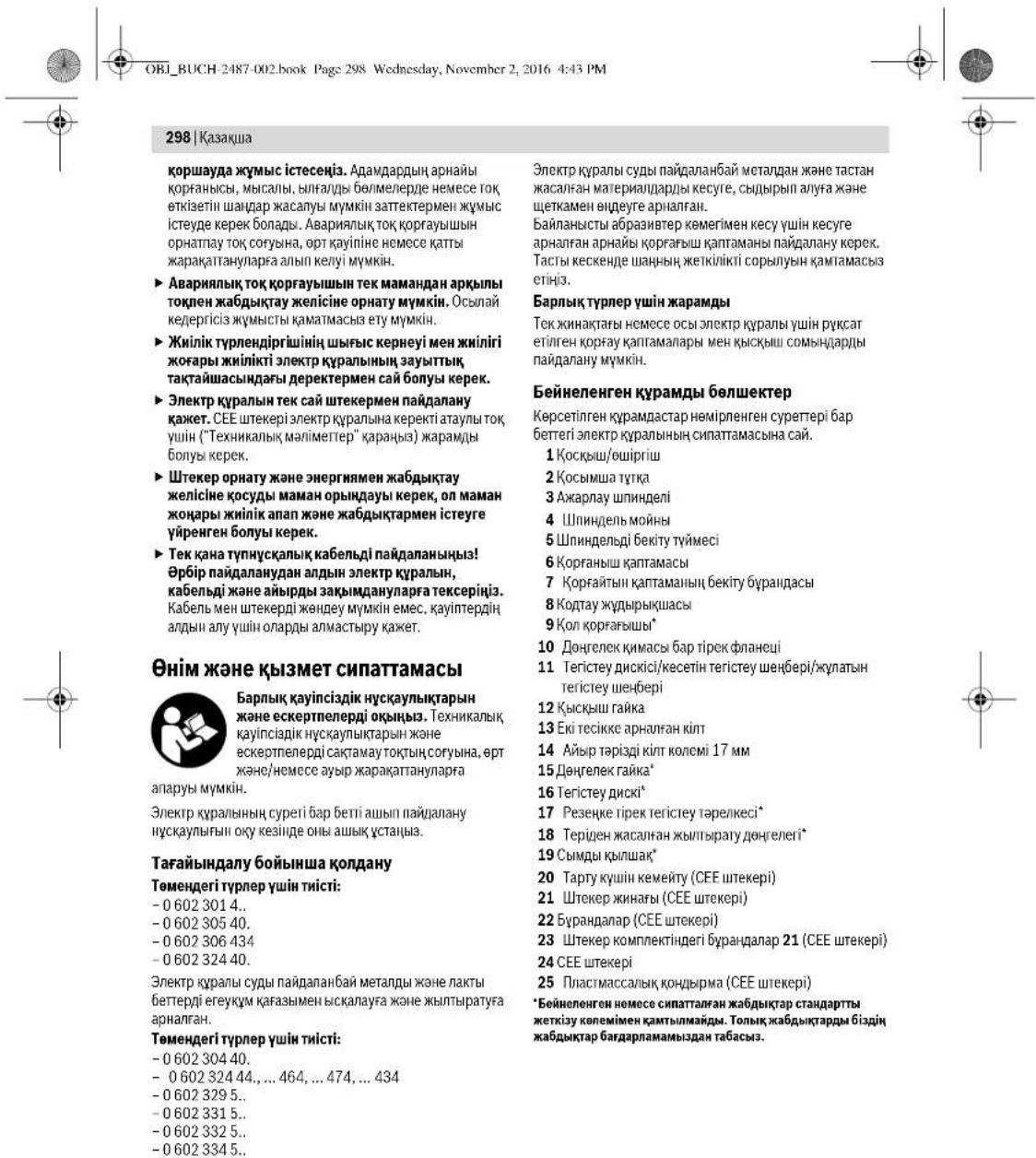
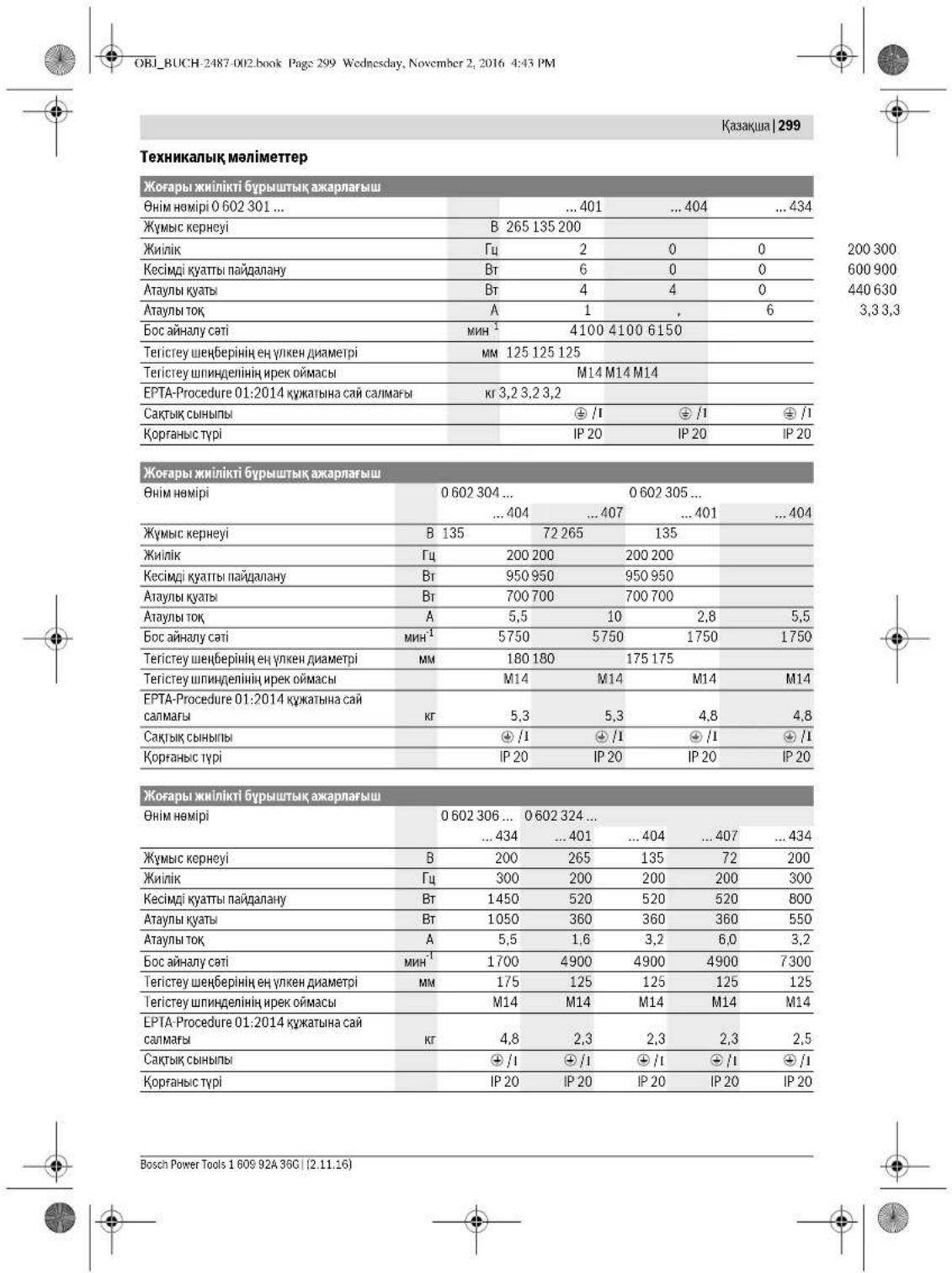
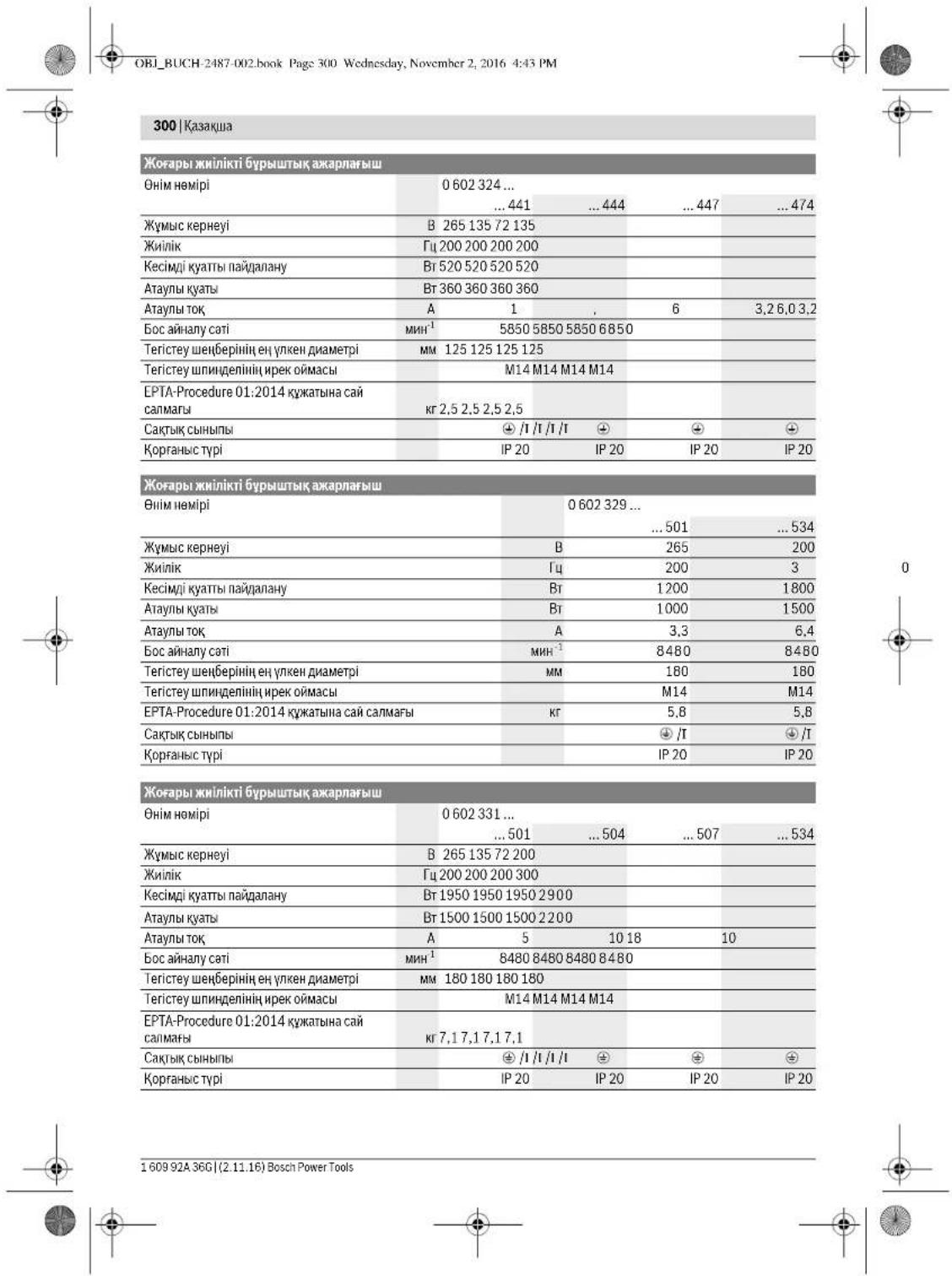
OBJ_BUCH-2487-002.book Page 301 Wednesday, November 2, 2016 4:43 PM
Kazakka 301
| Жогары жинникovi Бурштейх онлайнарлайы | |||||
| Одир | 0 602 332 ... | ||||
| ... 501 | ... 504 | ... 507 | ... 534 | ... 511 | |
| Жу mus керneyi | В 265 135 72 200 72 | ||||
| Жилік | ГИ 200 200 200 300 300 | ||||
| Кесimлі куаты падалану | Вt 1950 1950 1950 2900 2900 | ||||
| Атыны куаты | Вt 1500 1500 1500 2200 2200 | ||||
| Атыны тok | A 5 | 10 18 10 27 | |||
| Бос сөнүлү сati | MH1 | 6600 6600 6600 6600 6600 | |||
| ТerICTе ушенийцпен улken даметрì | MM 230 230 230 230 230 | ||||
| ТerICTe ушенийцпен рек омась | M14 M14 M14 M14 M14 | ||||
| EPTA-Procedure 01:2014 куатыни саïdмагь | Кr 7,1 7,1 7,1 7,1 7,1 | ||||
| СаKitь сынгь | ◎ /I | ◎ /I | ◎ /I | ◎ /I | ◎ /I |
| Коргань с typi | IP 20 | IP 20 | IP 20 | IP 20 | IP 20 |
OBI_BUCH-2487-002.book Page 303 Wednesday, November 2, 2016 4:43 PM

| 0.60232950. | 0.602329534 | 0.6023315.. | 0.6023325.. | |
| a₁ kānilbī Čeρбěny māni (vú 6aβhɪtbiŋBékθoɪpьik Kocbɪnɪdci) jæne K dʌnciádiRiEN 60745-2-3 CTaɪdaptrbɪha cai aɪhɒkɪtərɪŋ. | ||||
| Bettik Āxapnay (ndepeki Āxapnay): | ||||
| a₁ | M/c² | 7 | 7 | 7 |
| K | M/c² | 1,5 | 1,5 | 1,5 |
| Жыntыратy: | ||||
| a₁ | M/c² | - | - | - |
| K | M/c² | - | - | - |
| Aşxpapnay IXcKimen Āxapnay: | ||||
| a₁ | M/c² | - | - | - |
| K | M/c² | - | - | - |
| 0.602 334 50. | 0.602 334 534 | |
| А.М.н.б.л.г.н.р.н.з.л.с.к.р.л.ь.н.д.ы.б.с.к.у.ш.д.а.д.етe | 16 | 86 |
| Т.о.н.с.д.р.г.п.т.с.н.р.д.ы. | 16(A) | 97 |
| Д.д.ы.б.с.д.к. к.у.д.н.г.н. | 16(A) | 97 |
| О.о.ш.у. д.с.д.д.и. K | 16 | 3 |
| К.у.н.с.д.р.г.ы. к.р.д.ар.ы. к.н.д.и. | 16 | 3 |
| a,ж.л.р.ы.т.р.б.у. м.ан. (у.ш.б.с.д.ы.н. в.ektор.ы. кocьнд.ы.сы.) | 16 | 7 |
| Ж.о.н.с.д.р.г.ы. к.р.д.ар.ы. к.н.д.и. cay. an.ы.к.т.л.ан. | 16 | 3 |
| Б.с.т.х.л.ар. Na. (д.р.ек.х.л.ар. Na): | 16 | 7 |
| a, | M/c2 | 3 |
| K | M/c2 | 3 |
| Ж.х.л.ч.р.ы. | 16 | - |
| a, | M/c2 | - |
| K | M/c2 | - |
| А.х.ар. Na. (д.н.с.х.им. Ах.ар. Na): | 16 | - |
| a, | M/c2 | - |
| K | M/c2 | - |
OcEckeptnenepe6epinre dipinney npmeHEN 60745 epexecine He mnepehneren Eneye adici 6oynnnae eceienr 6oynn 3neKtp Kpa/napdi bip-bipimcn canbctbyyui nnanaanbnyi MyMKIN. Onipinney kyaanu nnaman onney yuuie de xapamdu
Bepinr dipin kemn eKpKpAunbHn Heriri Kmymbctap yuWepinr. Erep nKpKpau bKa Kmymbctap yuHtynipKepeKpXApakTpeMn BcA ananb Cannanbl acnntnap Mehen HEMece Ketimcis Kytymen naidanhanncn cpiDiney keMepei eerepei. Byn Kmybc BapbcHbArDaBipin Kyatbn AptPbUd.
Dipindepky ktytbn Hkctb EceTney yuH Kypan oWipinpTeK HcKocBIFAH 6011111111111111111111111111111111111111111111
JaananahyuibnipinepyacepienckatayuyinKocmbaay KAYinciikupanapabih konanyakket,McBcbl:3ekipt KypandbKaHAnAmnA-CanmAbacnaptApk KyT, KOpanpabibCTbHkyCTay,MyMHC agicTeepinyhBbBCTbp.
Caikecik MonimdeMeci
C
XKeKxayanKeppuiNiknHmEa "TexMknAblk ManimeTep" ne cnarranran HmHIn 2011/65/EU, 2016 Kxnn 19 calipinhe dHm:2014/108/EC, 2016 kxn 20 calipinhe coh 2014/30/EU, 2006/42/EC epekenepiheri bapknTHicti anHKtampanapa hsepictepi mehen bipre cakke ekehin XeThe Mehenderi Hopmanapara ca kexHH kenindeHdipem3 EN 60745-1, EN 60745-2-3, EN50581.
TeHHKAnBik KpKaTap (2006/42/EC) TEmeHderIeIe Robert Bosch Power Tools GmbH, PT/ECS, 70538 Stuttgart, GERMANY
Henk Becker Executive Vice President Engineering
Helmut Heinzelmann Head of Product Certification PT/ECS
iV. h = mc
Robert Bosch Power Tools GmbH 70538 Stuttgart, GERMANY Stuttgart, 01.01.2017
OBI_BUCH-2487-002.book Page 304 Wednesday, November 2, 2016 4:43 PM
304|Kasaika
XnHay
Kopranbiw Kaa6dbkTapbH ophaty
Kannbl Hcyckaynbikrap
Kab6bIkapBpeTey,benwekeptipnAnmaCTbpy Hemece3neKT KpAanB AakBpaTayd anBbH TOKTH ABHapBbHa. OcbCaKbIbApac3neKT KpAanBbH BaiKaCyCbKocLyuHaNKeBepMeiD.
Eckptne:Kc3HcTeTcrtey H6bepi 63bna Hmece Kopr4aBn KaTnAa3Nekr KpAa KpBnBnApBn 63bna,3NkPr KpAanBbipDcpeBnc K3MeTine X6bepy Kepe,MekehKaanPnayTbYbHuBaK3MeTkepeTyXeH naidanyHcyKehepeI rapayBnHkapAba.
Koprafiiu kantamalarabdi yukbiadapdni onepator karfaiba kapat yuuniabtiyedi etin opahbtsi.
Excerpt: KoprAflblu KaTAMamabHb KOnTaY KjduBpUkwnapBc TeK 3neKtp KpAnra JkaPaTbHn KoprAflb KaTAMahBb OPhATyDb KMaTAmCb3 etEdi.
Tericteyre aphanfah Koprafbkantama (A cypetin kapaht)
Tomehderitynpepywnthicti:
-060230440. -06023295..
The correct installation of the elements on the basis of the requirements of the operating instructions is the responsibility of the operator. The device must be stored in a dry place. To operate the device, it is necessary to connect it to a power source of 7-10 V.

The device must be connected to a power source (power supply, battery, or charger) with a voltage of 3 V. The device must be protected from short circuits. The device must be used in accordance with the instructions in this manual.
Tericey uniiuieni3 aibp kinnm 14 6epk yctan TypbHb. - Kibckwraikahki 12 raja kittimenn 13 ceparan Keqde aabp kittimnn 14 tericiy twnnleni hcnt anyt ypbbln. - Tericyr kapanb, api ipek fanehui tericyr mmnnnienin hubapnhia.
3neKtp KypaandapbI uHHndnbI 6yfaray nephecimen5
Tomehderiytpnpywnthicti:
-060232440 -0602324434 -060232444
llHnndnDik 6yfattay nepHeCi 5 bap 3eKtp KpIaNpaJa akapny aacnabHy opatya cObMydk KInTne Tipten TyOc kepB oBnMdui (E1-E2 eCetepHk KaPahua).
UHnHnBbI6KtYyMeCInTeKuHHnBnE ToKtTaBnFAn KHyde6acBbI3. 3HnTne3eNkTp KypaBnH 3akBmay MyMKH.
-Akpanay KypbIbnBcbn OPHATyDAN AINHINHNHINHINBdi Byrattay nepheci 5 Akpanay uHHNENIH 3 Byrattay yuH 6 bacn npEHNI 6acn YCTAH. - Kepekxi axapnay kypalbih opahatbua (Teriticey uheepiin, Kecetni teriticey uheepiin Hemece kcyjatbih Teriticey uheepiin Opya) 304 fertine kapaanu) - Ummnndnbi 6yfatay nephein 5 xibepin axapnay mmnnndnhi 6yfatanraa huihni3.
Please read the text before installation (instructions).
Safety instructions:
OBI_BUCH-2487-002.book Page 306 Wednesday, November 2, 2016 4:43 PM
306|Kazakh
Output
When using the device, it is necessary to strictly follow the safety instructions and recommendations given in this manual. The manufacturer is not responsible for damage caused by failure to follow these instructions.
Spare parts and accessories
Only use original spare parts and accessories. Using non-original parts may lead to malfunctions and void the warranty. If the device is damaged or shows signs of wear, contact a qualified specialist for repair. Do not use the device if it is damaged or if parts are worn out. Asbestos-containing materials are hazardous to health; follow safety precautions.
- The device must be used only for its intended purpose. Any other use is considered improper.
- The device is intended for household use only.
The device must be operated only with the specified voltage.
Do not use the device if it is damaged. Contact a qualified specialist.
Energy efficiency
To reduce energy consumption, the device should be turned off when not in use.
The device is intended for use in households, similar applications such as staff kitchens, offices, and other workplaces. The device must be connected to a properly installed socket. The device must be connected to a socket with a protective contact.
The electric crane control panel is designed for safe operation. Before starting work, the crane operator must be familiar with the control panel (classifier) and its functions.
Before operating the electric crane, the operator must check the correct connection of the control panel to the crane. The control panel must be connected to the electric crane's power supply according to the technical specifications. The control panel must be installed in a place accessible to the operator.
What is the procedure for connecting the control panel to the crane's electrical system and testing it?
See the connection diagram (see figures I1-I2).
- The two-button control panel (21) is mounted on the crane body. The plastic housing protects the electric components and the control panel from mechanical damage. The housing must be securely fastened with 20 screws.
The first button (23) is located on the front side of the control panel (21) and is used to control the L1 contactor.
The second button (L2) is used to control the L2 contactor. The third button (L3) is used to control the L3 contactor. The control panel is mounted on the front side of the crane body, above the 21-pin connector. The housing is secured with 20 screws. - The control panel (21) is connected to the crane's electrical system via a 24-pin connector. The housing must be properly grounded. - The electric crane's control panel (24) is used to control the crane's movements.
All maintenance and repair work must be carried out by qualified personnel.
Before starting maintenance or repair work, disconnect the crane from the power supply.
Do not operate the crane without proper grounding!
Do not operate the crane without proper grounding.
Before starting the crane, ensure that the emergency stop button is in the correct position.
If the emergency stop button is pressed, the crane will stop. To resume operation, release the emergency stop button and press the reset button.
The two-button control panel (21) is mounted on the crane body. - The control panel is connected to the crane's electrical system via a 24-pin connector. - The third button (L3) is used to control the L1 contactor, and the first button (L1) is used to control the L3 contactor. - The first button (23) is located on the front side of the control panel (21). - The control panel (21) is connected to the crane's electrical system via a 24-pin connector. - The housing must be properly grounded. - The electric crane's control panel is not waterproof.
Paiandaanhy
To connect the power tool to the mains, a plug must be fitted to the power cord. Before use, check the power cord for damage. If the power cord is damaged, do not use the tool. Do not use the tool if it is wet or damp. Caution:
160992A36G|(2.11.16) Bosch Power Tools






OBI_BUCH-2487-002.book Page 307 Wednesday, November 2, 2016 4:43 PM
Kazakh 307
The power tool is intended for cutting metal. The power tool must be used only with the appropriate cutting wheel.
For cutting with a cutting wheel, use only the cutting wheel guard. The cutting wheel guard must be adjusted so that the exposed part of the wheel is as small as possible. The cutting wheel guard protects the operator from fragments and accidental contact with the wheel.
Always use the cutting wheel guard when cutting.
For cutting with a cutting wheel
Before cutting, check that the cutting wheel is correctly mounted and free of cracks or damage.
Always use the correct cutting wheel for the material to be cut.
Cutting with the cutting wheel – Safety instructions (see figure 1)
The following instructions are important:
-06023244
- Use only cutting wheels with a maximum speed of at least 1 x the rated speed. - For cutting with a cutting wheel, use only the cutting wheel guard. - Use only cutting wheels with a diameter that fits the tool.
Electric rotary switch (see Figure 2)
The following types are available:
-06023014. -06023295. -060230440. -06023315.. -060230540. -06023325.. -0602306434 -06023345.
The electric rotary switch is supplied in one version, with or without a handle.
- For the version with a handle, the handle is supplied in one version. For the electric rotary switch without a handle, the switch is operated by a key or a special tool.
Safety instructions
Before installation, commissioning, or maintenance, disconnect the electric rotary switch from the power supply. If these instructions are not followed, the switch may be damaged or cause injury. Only qualified personnel should work on the switch. Do not touch the switch with wet hands. Do not operate the switch if it is damaged or if the housing is open.
After disconnecting the electric rotary switch from the power supply, wait at least five minutes before opening the housing.
Connection terminals and connection
The connection terminals (switch) must be connected with the correct polarity. The connection terminals are marked with the corresponding symbols. The connection must be made with the correct cross-section and the correct tightening torque.
Metal housing (see Figure 3)
The metal housing must be connected to the protective earth conductor.
After connecting the terminals, the cover must be closed. Do not operate the switch without the cover. If the cover is damaged, replace it immediately.
The electric rotary switch must be installed in a suitable enclosure. The installation must be carried out by qualified personnel. The switch must be protected against moisture and dust.
The manufacturer cannot be held liable for damage caused by improper use. Use only as intended. The power tool must be used only with the tools specified in these instructions.
The power tool is intended for cutting and grinding materials. To use it safely, you must follow all safety instructions and warnings provided in this manual.
Electric tools must be operated only with the specified voltage. Check that the voltage matches the power supply. Use only the original accessories and spare parts. Electric tools must be used only with the accessories listed in these instructions.
The tool must be used only with suitable materials such as metal, wood, plastic, and similar. Do not use the tool for purposes other than those intended. Always wear appropriate personal protective equipment and follow all safety instructions.
Only use the tool with the correct power supply. Check the material, tools, and accessories before use. Always follow the safety instructions.
Bosch Power Tools 1609 92A 36C (2.11.16)




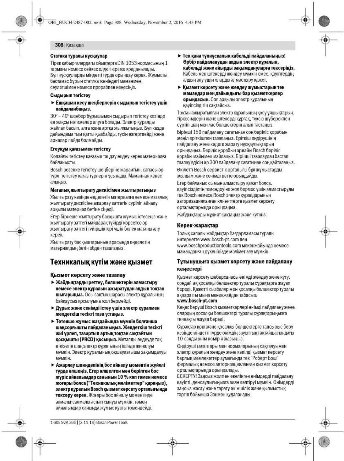
310 Romana
OBI_BUCH-2487-002.book Page 326 Wednesday, November 2, 2016 4:43 PM
326|Bulgarian
If you do not follow the instructions and warnings, the consequences could result in electric shock, fire, and/or serious injury.
Power tools can be dangerous if used incorrectly. Failure to follow the safety instructions can lead to electric shock, fire, and/or serious injury.
General safety instructions for working with power tools: keep the work area clean and well lit, do not operate power tools in explosive atmospheres, and keep children and bystanders away while operating a power tool.
The power tool is intended for driving and removing screws. When using the tool, always hold it firmly with both hands. The reaction torque of the motor can cause the tool to twist unexpectedly. Always use the auxiliary handle if provided, to maintain control. Do not use the tool if the switch does not turn it on and off. Any tool that cannot be controlled with the switch is dangerous and must be repaired. Always remove the battery pack before making any adjustments, changing accessories, or storing the tool. Such preventive safety measures reduce the risk of starting the tool accidentally. When the battery pack is not in use, keep it away from other metal objects, like paper clips, coins, keys, nails, screws, or other small metal objects, that can make a connection from one terminal to another. Shorting the battery terminals together may cause burns or a fire. Under abusive conditions, liquid may be ejected from the battery; avoid contact. If contact accidentally occurs, flush with water. If liquid contacts eyes, additionally seek medical help. Liquid ejected from the battery may cause irritation or burns. Do not use a battery pack or tool that is damaged or modified. Damaged or modified batteries may exhibit unpredictable behavior resulting in fire, explosion, or risk of injury. Do not expose a battery pack or tool to fire or excessive temperature. Exposure to fire or temperature above 130°C may cause explosion. Follow all charging instructions and do not charge the battery pack or tool outside the temperature range specified in the instructions. Charging improperly or at temperatures outside the specified range may damage the battery and increase the risk of fire.
The power tool is intended for driving and removing screws.
Safety instructions for working with the machine. Use the supplied attachment when working with the dust mask, for protection against inhalation of harmful substances. If necessary, work with a respirator (antidust), protective glasses, and a special protective suit that prevents dust from entering the body. They must protect the exposed parts of the working area. The protective equipment or its use may cause hazards during work. If prolonged exposure to loud noise occurs, it may lead to hearing loss. Pay attention to others to ensure safe operation in the work area. Everyone present in the work area must wear personal protective equipment. Open rotating parts of the machine or tools can cause injury. To avoid injury, keep a safe distance from the rotating parts. When there is a risk of the tool coming into contact with hidden electrical wiring, hold the power tool only by the insulated gripping surfaces. Contact with a live wire may energize the metal parts of the power tool and cause an electric shock. Keep the power cord at a safe distance from rotating parts of the tool. If the cord is damaged or entangled with the power tool, it may be cut or caught by the rotating tool, which could cause an electric shock. Never leave the power tool unattended while it is running. Rotating parts of the tool can cause injury, and you may lose control of the power tool. While operating the power tool, do not leave it switched on. If you are distracted or interrupted, you may be injured by the rotating tool, and the tool may be thrown into your body. Regularly check the ventilation openings of the power tool. The turbine of the electric motor draws dust into the housing, and the accumulation of metal dust can cause an electric shock. Do not use the power tool near flammable materials. Sparks can ignite dust and such materials. Do not use the tool if it is damaged or if its temperature is abnormal. A damaged or overheated tool can cause an electric shock.
Kickback and related warnings
Kickback is a sudden reaction of the machine due to jamming or blocking of the rotating tool, e.g., a grinding disc, a cutting disc, a wire brush, etc. Jamming or blocking of the rotating tool

Bulgarian 327
The power tool is suddenly thrown in the opposite direction of the rotation of the tool. As a result, the power tool is thrown with great force in the direction of the operator, and the tool may become uncontrollable.
If, for example, a grinding disc gets jammed or stuck in the workpiece, the edge of the disc that is being used may be thrown out, and the disc may break or cause a kickback. In such a case, the disc may be thrown towards the operator or in the direction of rotation, depending on the direction of rotation and the point of jamming. In such cases, the grinding discs may also break.
The tool is designed for professional use. Improper use of the power tool can cause malfunctions. This can be prevented by following the safety measures described below.
Always hold the power tool firmly with both hands and position your body and arms so that you can counteract the kickback forces. If the power tool has a side handle, hold it with both hands, and position yourself properly to react to kickback or sudden reactions during operation. If you follow the safety measures, you can avoid kickback and sudden reactions. Never place your hands near the rotating accessories. If kickback occurs, the tool may jump towards you. Release the trigger immediately and keep the power tool under control. Kickback is the result of misuse of the tool and can be avoided by taking the precautions described below. Be especially careful when working in corners, edges, or sharp edges. Avoid bouncing or snagging the tool. When working with the tool, always use the auxiliary handle if provided. There is a risk of injury if the tool is not held properly. Always maintain control of the tool and never use the tool without the guard. Do not use the tool without the guard properly installed. Always use the guard provided with the tool.
Special safety instructions for grinding and cutting with abrasive discs
Use only the abrasive discs that are approved for your power tool and that are intended for the specific application. Discs that are not approved for the power tool cannot be properly guarded and do not guarantee safe operation. The guard must be mounted so that the exposed surface of the disc does not protrude beyond the guard. Incorrect
Mounting of the disc, which may occur if the disc is not properly seated, can cause the disc to break. Always ensure that the disc is properly mounted and that the guard is in place.
The tool guard must be provided with the power tool to ensure maximum degree of protection so that the operator of the power tool is exposed to the possibility of contact with the abrasive disc. The tool guard protects the operator of the power tool from open rotating parts, abrasive disc contact, sparks, and flying debris that may increase the risk. It is allowed to use abrasive discs only for the applications for which they are intended. Never use the tool with a cutting disc for grinding, or with a grinding disc with a cutting edge for removing material. The guard cannot be used for cutting. Use the appropriate guard for the application. When using the tool with a grinding disc, the guard must be positioned to deflect sparks away from the operator. Using a suitable guard reduces the risk of disc breakage and increases safety. The guards for cutting discs may be used for cutting applications. Use only abrasive discs from reputable manufacturers. Discs for larger power tools are not suitable for use with smaller tools. Discs for larger machines are designed for higher speeds, which are higher than the speeds of smaller tools, and they may shatter.
Special safety instructions for grinding discs
Never use a damaged disc or one that has cracked. Do not use blunt or damaged discs. A damaged disc increases the risk of injury from activation or from the disc breaking, which can cause kickback or the disc shattering while rotating. Avoid placing your hands in the area in front of or behind the rotating disc. When the disc is at a flat angle, in the event of kickback the power tool may be thrown towards you or away from you. If the disc becomes jammed or when you pause work, switch off the power tool and hold it still until the disc has completely stopped. Never attempt to pull the rotating disc out of the cut, as this may cause kickback. Determine the cause of the jam and do not switch on the power tool again until the disc is free. Pay attention to the direction of rotation and do not force the disc to reach full speed while it is in the cut. In the opposite case, the disc may jam, jump, or kick back.


328|Bulgarian
Support large workpieces to prevent the risk of kickback from the cutting disc. Large workpieces may sag under their own weight and must be supported on both sides, both near the cutting line and at the outer edge. Be especially careful when cutting into existing walls or other areas where you cannot see what is behind, as the disc may cut into gas or water pipes, electrical wiring, or other objects.
Special safety instructions for working with circular saws
The tool is intended for cutting cigarettes, follow the instructions for the size of the cigarette. These cigarettes, which are suitable for standard filters, may cause irritation and also to be used for the opening and tearing of the cigarette or for the occurrence of defects.
Special instructions for safe work with the tool
Do not leave metal objects near the blade. When cleaning, if the blade has a cleaning loop, adjust it or replace it. The cleaning loop can be removed to increase the visibility of the blade around the guard.
Special instructions for safe work when cutting walls and fabrics
Do not press, as during normal operation the blade should not be extended. Do not extend the blade. Press it against the material. Open the blade guard. The blade should be retracted after each cut. If using the tool with the guard, the guard should be adjusted so that the blade does not extend beyond it. The cutting edges and fabrics may increase the risk of injury due to the sharpness of the cutting edges.
Additional instructions for safe work
Work with the tool.
Use similar tools to open the ventilation slots on the surface of the pipe, or attach them to the lighting fixture. The tool with a power cord may cause fire and electric shock. The tool and its accessories may cause electric shock. The tool and its accessories have a large material for the user and may cause electric shock.
If the power tool is used for cutting (cutting of material or for other purposes outside the scope of the tool), the user should be properly trained. This prevents unintentional activation of the electric tool. Do not touch the cutting discs, they may be hot. During work, the discs become hot. The work of the electric tool is safe if you maintain a stable position of the body. With both hands on the electric tool, it is more stable. Ensure the ventilation holes are clean, hold the tool with a firm grip, and do not overreach. Keep proper footing and balance at all times. Connect the electric tool to a properly grounded power supply. The contact and the ventilation openings must have proper protection and the power cord.
Instructions for safe handling of high-voltage electric tools
Warnings for work and safety for frequency converters must be observed. Detailed information about this is provided in the operating instructions of the frequency converter. The frequency converter must be protected with a residual current device (RCD) if used in systems where a longer protective conductor is required. The protective conductor length is not specified. It is necessary to operate in damp rooms or with materials that generate conductive dust. If a residual current device (RCD) is not used, the consequences can be electric shock, fire, or serious injury. The use of a residual current device (RCD) is permitted only if it is installed in the supply circuit of the device. It is possible to ensure trouble-free operation of the output voltage and frequency of the frequency converter only if the data specified on the rating plate of the high-frequency converter are observed. The device may be operated only by qualified personnel. The device must be connected to the mains and disconnected from the power supply only by qualified personnel who are trained to work with high-frequency devices. Use only approved protective equipment when working on the device.



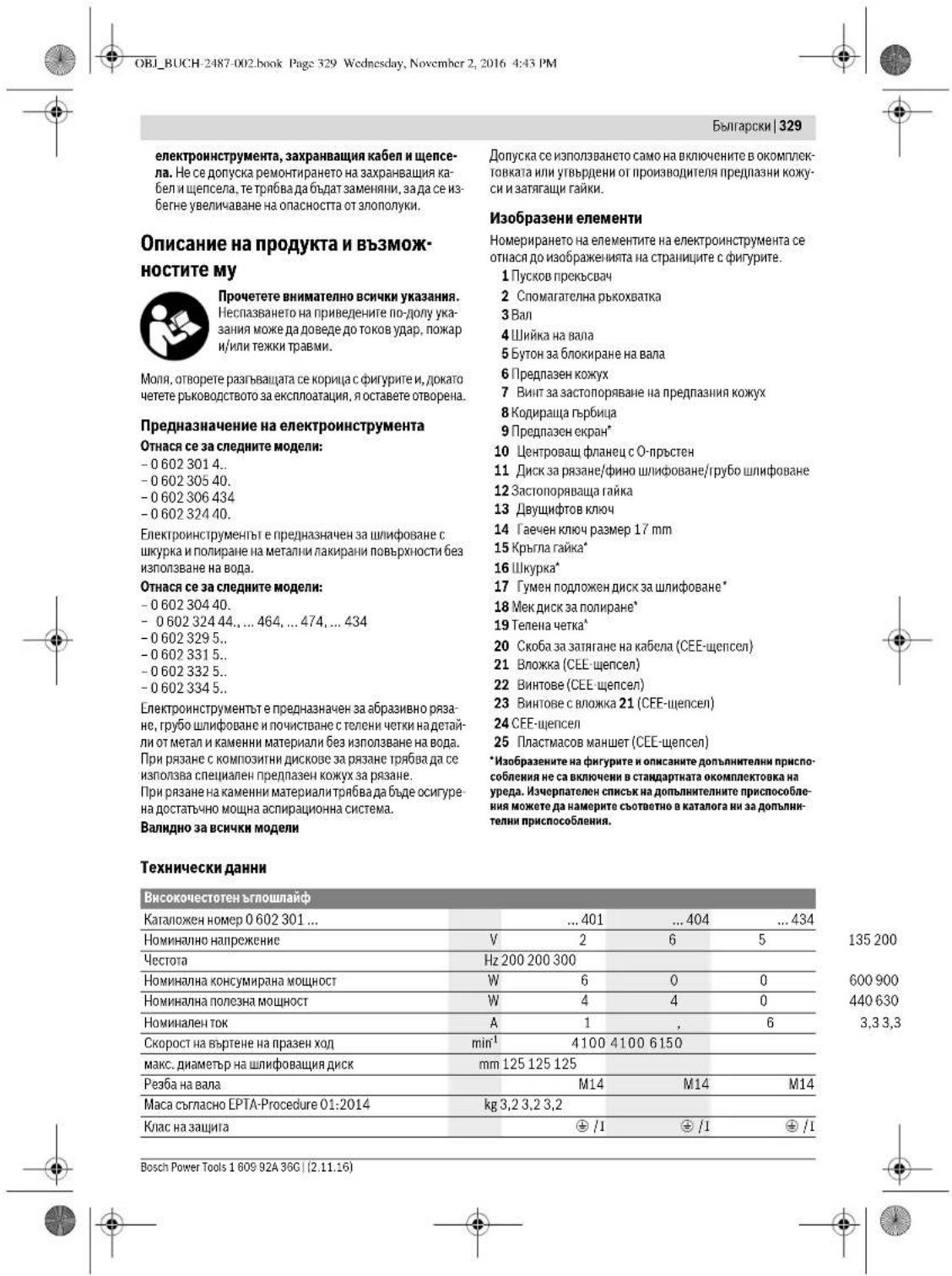
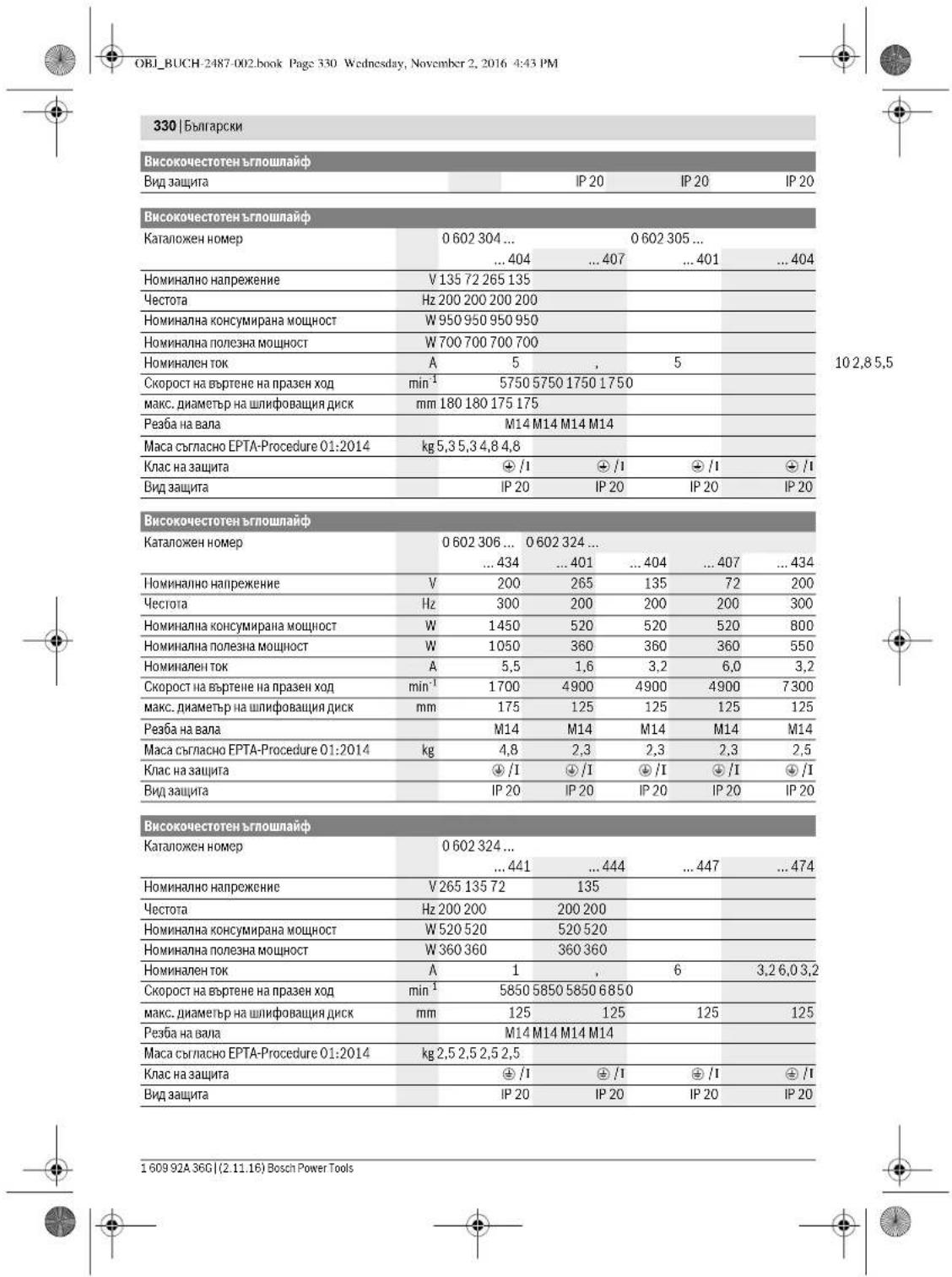
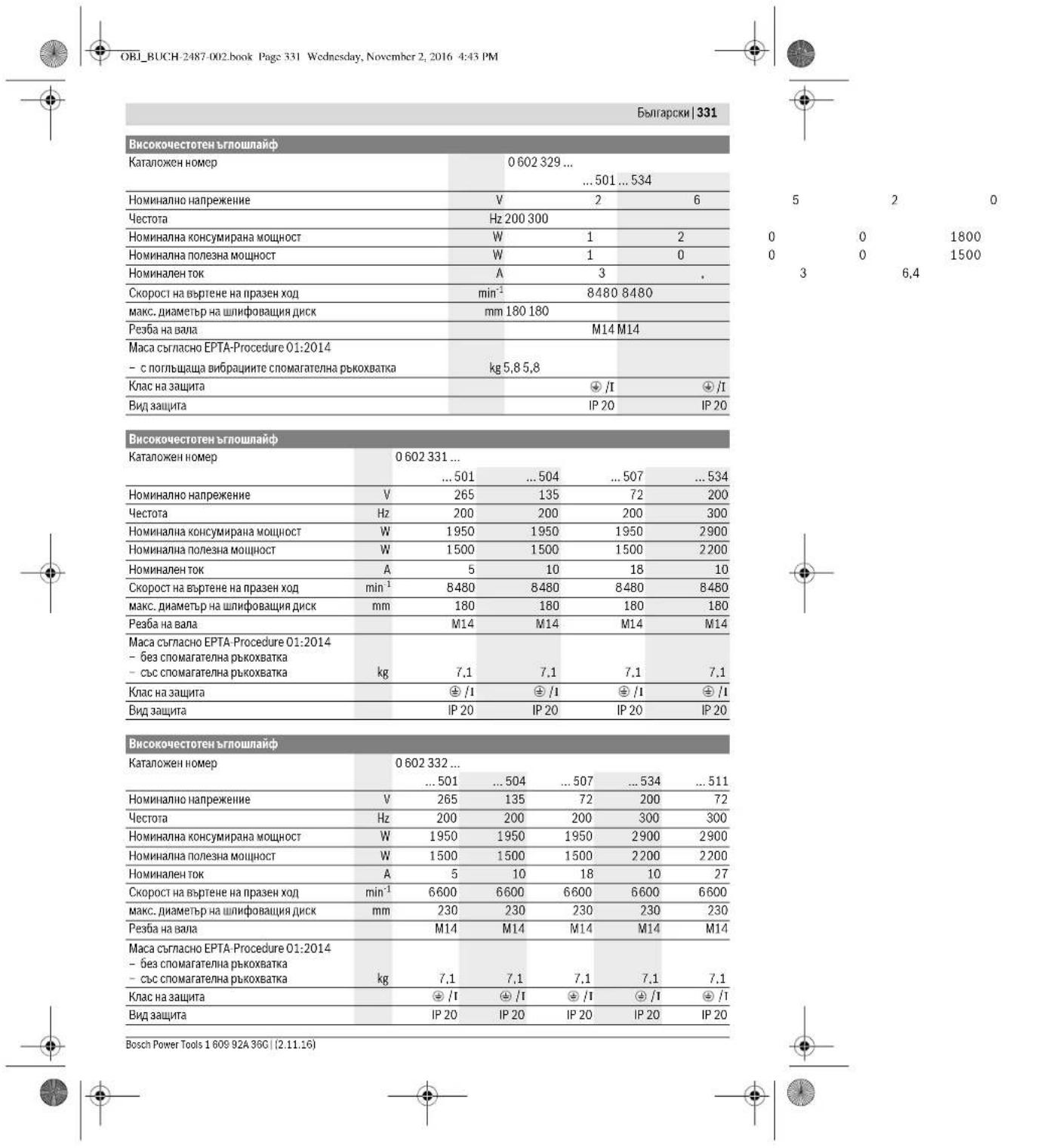
332|Bulgarian
| Ви这样做�能帮您打赢仗吗 | ||||
| Каталожен Homep | 0 602 334 ... | |||
| ...501 | ...504 | ...507 | ...534 | |
| HommaHann no Hanpejene | V 265 135 72 200 | |||
| Yectota | Hz 200 200 200 300 | |||
| HommaHann koncympana moihoct | W 2500 2500 2500 3800 | |||
| HommaHann no ne3ha moihoct | W 2200 2200 2200 3100 | |||
| HommaHann ToK | A 6 | . | 7 | 13,2 24,7 13,2 |
| Скорост на Вьтende на праzenход | min-1 | 6600 6600 6600 6600 | ||
| мас диметр нашифовачи дисс. | mm 230 230 230 230 | |||
| Рezба на вала | M14 M14 M14 M14 | |||
| Мас сбгасно EPTA-Procedure 01:2014 -绛з сногамателна рыковатka | kg7,87,87,87,8 | |||
| Клас на зашипа | + /T | + /T | + /T | + /T |
| Вidдацита | IP 20 | IP 20 | IP 20 | IP 20 |
Safety instructions
The device contains a high-frequency system and requires a variable frequency current according to the data on the rating plate.
To ensure the frequency, the device must be connected to a frequency converter (see connection to power supply, page 336).
The vibration emission values are determined according to EN 60745-2-3.
Standard vibration and noise
| 0.60230140. | 0.602301434 | 0.60230440. | 0.60230540. | |
| Равишиeto I Ha Ильчваима ум обикно- вениe | ||||
| Равишиeto Ha зуковою налгане | dB(A) | 72 | 82 | 79 |
| Мошост Ha зува | dB(A) | 83 | 93 | 90 |
| Ношpeденист K | dB | 3 | 3 | 3 |
| РавOTe creшуоагн'te: | ||||
| Пьіната стейност Ha Вибрацпte a, (be- Ктосята сума по trпе налравелени) in ношpeденист Ka оретени Stb- trаласno EN 60745-2-3. | ||||
| Шифobaning(rpy6ошнфobaning): | ||||
| a1 | m/s2 | - | 5,3 | 5 |
| K | m/s2 | - | 2 | 2 |
| Полигане: | ||||
| a1 | m/s2 | 3 | 3 | - |
| K | m/s2 | 1,5 | 1,5 | 1,5 |
| Шифobaning cшкypka: | ||||
| a1 | m/s2 | 3 | 3 | - |
| K | m/s2 | 1,5 | 1,5 | 1,5 |
Bulgarian|333
| 0 602 306 434 | 0 602 324 40. | 0 602 324 44. | |
| 0 602 324 464 | |||
| 0 602 324 474 | |||
| 0 602 324 434 | |||
| Пьлесастийск на Вибраценте a1 (Векторнаты cума по Тритахапалени) и неор federеленocстуК са ор federelenы сълесно EN 60745-2-3. | |||
| Шимфobанe (груюшимфobанe): | |||
| a1 | m/s2 | - | 6 |
| K | m/s2 | - | 2 |
| Полиганe: | |||
| a1 | m/s2 | < 2,5 | 4 |
| K | m/s2 | 1,5 | 1,5 |
| Шимфobанe сшкуka: | |||
| a1 | m/s2 | < 2,5 | 4 |
| K | m/s2 | 1,5 | 1,5 |
Bulgarian|335
Display (see Fig. C)
For special models:
-06023014. -060232440 -060230540. -0602306434
Work with the cutting disc only after reading the safety instructions. Use the protective guard. The guard is attached with the auxiliary handle 2.
Mounting the cutting tools
Before adjusting the power tool, replacing working tools and accessories, switch off the power tool and remove the battery. This precaution prevents accidental starting of the power tool. Always use the correct working tools for the material to be processed. Do not use damaged or worn discs - replace them with new ones. When mounting, ensure that the tool is clean and dry. After mounting, check that the cutting disc is correctly fitted and can rotate freely. Make sure that the cutting disc does not touch any part of the power tool.
Mounting the cutting disc for cutting, roughing or fine cutting (see figures D1 - D2)
Suitable discs:
-060230440. -06023315.. -060232444...464. -06023325.. ...474...434 -06023345.. -06023295..
Mounting
Make sure that the correct cutting guard is fitted (see "Mounting the cutting guard" on page 334). - Place the centering flange 10 on the spindle 3. Around the collar for the working tool on the centering flange 10, place the O-ring. If the O-ring is missing or damaged, replace it with a new one. - Place the cutting tool 11 (for cutting, roughing or fine cutting) on the centering flange 10, aligning the inner hole with the spindle 3. Place the clamping nut 12 on the spindle thread so that the collar faces upward. - Tighten the clamping nut 12 with the two-pin wrench 13, while simultaneously holding the spindle lock 14 to lock the spindle 3, until the tool is securely clamped.
Removal
- Lock the spindle with the spindle lock 14
- Loosen the clamping nut 12 from the spindle with the two-pin wrench 13, while holding the spindle lock 14, until the tool is released.
- Remove the cutting tool and the centering flange from the spindle.
Power tool with spindle lock button 5
Suitable discs: -060232440 -0602324434 -060232444 Power tool with spindle lock button 5. To lock the spindle, press and hold the spindle lock button. Mounting working tools for cutting (see figures E1-E2). Press the spindle lock button until the spindle locks. Do not operate the power tool with the spindle lock engaged - it may be damaged. - For mounting the working tool, press the spindle lock button 5 to lock the spindle 3. - Mount the cutting tool (see Mounting the cutting disc for cutting, roughing or fine cutting, page 335). - Release the spindle lock button 5 to free the spindle.
Mounting the cutting guard (see figure F)
Other than this 3a cneHnTe modenH:
Bulgarian | 337
- Check the device for correct connection. In the case of CESE-24, connect the power tool to the electrical outlet.
You can connect the frequency converter to the power supply.
When connecting the frequency converter to the power supply, follow the instructions for commissioning the frequency converter.
Then check the direction of rotation!
Checking the direction of rotation
The direction of rotation must match the arrow on the power tool.
If, when switching on (see Switching on the power tool, page 337) the tool rotates in the opposite direction, you must switch off the power tool and disconnect the power supply.
- Turn the screw 22 and remove the cover 21 and the CESE-24. - Loosen the clamps for the neutral and phase conductors and remove them. Then insert the phase conductor L3 into the terminal, and the neutral conductor L1 into terminal L3. 3- Tighten the screws 23 into the cover 21 to secure the conductors. Insert the cover 26 and close the CESE-24. Then tighten the screw 22. - Finally, check that the phase conductor is correctly connected. - Then switch on the power tool to the power supply.
Working with the power tool
Switching on
The frequency of the power source must match the data on the nameplate of the power tool. Check the working tools before use. The working tool must be mounted securely and rotate without wobbling. Allow the tool to run unloaded for at least one minute. Do not use damaged, cracked, or vibrating working tools. Damaged working tools may break and cause injury. Press the switch 1 to the "ON" position. The power tool operates at full speed. Press the switch again to switch off. This prevents uncontrolled restarting of the power tool.
Before switching on the power tool again, check the power source (see "Power source", page 336).
The instrument is a power tool. To connect the power tool to the mains, the power tool must be switched off. Before connecting, check that the mains voltage matches the voltage on the rating plate.
Switching the power tool on and off
To switch on the power tool, first switch on the mains switch. Then press the trigger switch.
Switching on and off with the trigger switch (see figure 1)
For the following models:
-06023244 - To switch on the power tool, press the trigger switch. - To lock the trigger switch, press the trigger switch and hold it in the locked position. - To switch off the power tool, release the trigger switch.
Press the trigger switch fully, then release it to switch off.
Switching on and off with the lock button (see figure 2)
For the following models:
-06023014.. -06023295.. -060230440. -06023315.. -060230540. -06023325. -0602306434 -06023345..
- To switch on the power tool, press the lock button and then the trigger switch.
- To lock the trigger switch, press the trigger switch and hold it in the locked position.
- To switch off the power tool, release the trigger switch. If the trigger switch is locked, press it again and then release it.
Working advice
Before any work on the power tool, remove the battery from the power tool or disconnect it from the mains. This prevents accidental starting. Be careful when working on the power tool, especially when changing accessories or attachments. Always wear protective gloves. Do not operate the power tool in explosive atmospheres. Keep the power tool away from heat sources. Do not expose the power tool to rain or moisture. If the power tool is damaged, have it repaired by a qualified person. Do not operate the power tool if it is damaged. Always keep the power tool clean and dry.


338|Bulgarian
Operation with dust extraction
The dust extraction (accessory) can be operated at the mains voltage.
The dust extraction is significantly more powerful, quieter and slightly larger than conventional dust extractors.
Metal cutting (see figure)
For cutting with abrasive cutting discs, use the protective guard for cutting.
When working with the tool, always hold it firmly with both hands and ensure a secure stance. Do not touch the cutting disc, do not brake it, and do not subject it to lateral pressure.
When switching on the power tool, do not apply excessive force; press the two buttons.
The power tool must be operated in the direction opposite to the cutting direction. Otherwise, there is a risk of uncontrolled movement of the tool.
When cutting, always guide the tool correctly and carefully to avoid damaging the material.
Cutting stone materials
When cutting stone materials, always use the dust extraction. Work with a protective mask. Only use the power tool for dry cutting or dry grinding.
When cutting stone materials, always use the diamond cutting disc. For cutting and grinding, the protective guard must be used with the cover.
Use the power tool only with the dust extraction system and wear a protective mask.
The system is certified for work with stone dust. The company offers a wide range of accessories.
Including power tools delivery, the first part of the price is due within two years. Use power tools carefully, in accordance with the supplied material.
Adjusting the special material and the disc speed. The diamond disc can be replaced and checked. Instructions for this are given in the manual.
In case of impact, the diamond disc may overheat. Let it cool down by running it at no load for a while.
Significant speed reduction when cutting may indicate that the diamond disc is worn. You can replace it with a suitable one for the material. For example, a soft-bond disc.
Instructions for static load
The connection and installation must comply with the standard DIN 1053 Part 1 and the relevant national regulations.
These instructions must be strictly followed. For the installation of the product, consult with the responsible structural engineer, architect, or construction manager.
Pipe cutting
Never use cutting discs for rough cutting.
The angle of 30-40 degrees during cutting will achieve the best results. Use power tools with moderate pressure. The treated parts must be cooled, the surface may change color and deep grooves may form.
Cutting with a disc with a soft bond
The choice of the appropriate disc is made quickly with the selection of materials.
The company offers a wide range of discs, suitable for the material and the disc. Consult with your dealer.
Support with a support disc
The surface of the workpiece may become hot during operation. Never touch it with bare hands. Use protective gloves when handling the workpiece. After each pass, allow the surface to cool.
Service
Maintenance and cleaning
Before adjusting the power tool, replacing accessories, or storing the tool, disconnect it from the power supply. This preventive measure reduces the risk of accidental starting. For safe and efficient operation, keep the power tool and its ventilation slots clean. In dusty working conditions, clean the ventilation slots regularly and use a residual current device (RCD).
Metal dust generated during operation may accumulate on the power tool. This can be hazardous and may cause electric shock.
Macedonian|341
Use the electric appliance, accessories, and attachments according to these instructions, taking into account the working conditions and the work to be performed. Using the electric appliance for operations different from those intended could result in a hazardous situation.
Service
Your electric appliance should be serviced only by qualified personnel using only identical replacement parts. This will ensure that the safety of the electric appliance is maintained.
Safety warnings for angle grinders
Safety warnings for grinding and cutting-off operations
Important safety instructions:
-06023014. -060230540. -0602306434 -060232440.
This electric appliance is not intended for use by persons (including children) with reduced physical, sensory or mental capabilities, or lack of experience and knowledge, unless they have been given supervision or instruction concerning use of the appliance by a person responsible for their safety. Children should be supervised to ensure that they do not play with the appliance. Do not use the appliance for purposes other than those intended. Using the appliance for operations different from those intended could result in a hazardous situation.
Safety warnings for grinding and cutting-off operations with wire brushes
Back 3a CneHnTe TnIOBn:
-060230440. -060232444,..464,..474,..434 -06023295 -06023315. -06023325. -06023345
Oboj eektpnH anapat ce npntpe6yba Kako anata Ka 3a BpCSeBc, HJHuaH aTeKa n BpCynHs 3a ceebe Co BpCynn NIOoH. BHMNAbae HA CTe 6E6NEHOHN HANOMEH, yNATCTBa, pNkAaH N NOaTOU Hi TO CTn DObHne BO pNPnOR hYEpdOT. DOKOKny HE BHMNabe Ha CnENHTe yNATCTBa, MOKe Jda NoJeD o eektpnH ynap, NOKAP hNfH TNeuHK NOBEPdN. OeKTHnAnapHe norOed3a6pycebe co 6bpychaXapnHa nonnpabe.10kONky ro KOPHCTte EeKTHNOnanpat3a HECOOBETHNHAMEHNOKE da cepeHNBbKa onaOHCTN NOBpEe
Onth6e36dnochn Hanoemn 3a 6pycehe,6pycehe co 6pychaXapTna,pa0teHe co KxHauHHyETK,nonpahe en cepehe co 6pycnH nOoH Baxk 3a CHTNEONB
He KopHCTeTe npHbOp wTo He e CneuJnHO npEdBnDe HnpenopuaHOn odPm3BODHTENOT Ha OBOjEneKTPhueh anapat. He Bn e3aIapAnHaHaBe36dHaTaNtpeBa, cAmOzapAn Phakot Deka npHbOpOT MoeK Da ce npHcPcTn H aBauNt EneKTPhueh anapat. 103B0BENHOT 6poj Ha BPTEXH Ha anatot wto ce BMETHYBA MOPA da 6hde HTO TONKY BCOK KAKO hAJBCOKHOT 6poj Ha BPTEXH HABeHn Ha eNEKTPNHHOT anapat. PInb6opot kJc beptn no6p3o oddo3BOIChOT MOKeJa cCkPHN Da JneTHe OD anapatoT. HAdBoeepnHOTnJAmetapHe6eHHATAHaAnatot 10tCeBMETbMyBmopAdaOgOBaPaatHaMmEH3NHTe HaBaHOTnEKeTPnHApanatp. IOrpeHo DmEH3HOHNpaHte anataa BMETbYBaHe Me Moke DOBOHNO Da Ce 3auTHTa HIO KOHTPOHpaT. ATHTTE 3A BMEHYBABe CO HABO MOPa TOHO Da OIOBAPaH A HABOJOT HA BPTENHO 3a 6pycebe. Kaj ANATHE 3A BMEHYBaBe, ITO CE MOHTNaP aC NOOMU INPpA6Hnua, DHAJAMETOp HA DYNkata HA anatot WTO CE BMETHyBaMOPa OAOBpaHa ABmApetop Ha npHpatoH pAnpHbAua.AnATITE 3a BMETHyBABe HE MOKE TOHO DA CE PNIUPCBtAT HA ENEKTPHNHOT anapat, BCTPAT HePAHMNePO, BH6pPaAT MHORY JAKO HMOKE da BOEepaDo YIcbe HA KOHPTONpa. He KOPCHTe OUITETEH ANATI 3a BMETHYBAbe.Ipead Cekoe KOpHCTBe, npOBepTe rAnatite WTo CE BMETHyBaAT KAKO HA Ip. dANH BpCHNTE NPOHN HMA CKNHAT DenOBn Hnpouen, DnHn Ha BpChnTe DnCKOBn HMa NyKTHAHNN, dANH CE nCTPOeHN HnH N3AbEHn, nDANH MOnaONaBaeHN HnK CPKEN HXnHa HxHnA HtKa. DOKOKBY NnADNE ENEKTPHHHOT Anapar HnH Anatot ITO CE BMETHyBA, npOBepete dAn e OUTETBN HnN AKynOTpehe HeoHTETEN anat 3a BMETHyBaBe. OTKAKO CTro npOBepHne H CTABHne Anatot 3a BMETHyBaBe, HnE MoD30NYbJaTe HA NnHATA Da 6HdAT Bo 6m3nHa HnHBTO HnBKYehHOTan APAT H octabe Tg Anapatot DA BPTN EdHa MHNYta HaJBNCOCBpoj HA BPTEK. TObeKeTo OD, OUIETeHNTA aAttna 3a BMETHyBaBe Ke ce cKPIwAT BO TEKT O HA OBOJ probeni nepoiD. Hocete 3aunHTNa onepMa.Bo 3aBHCNOCT Oy nOHTb6ata, Hocete eueoNc3aunHTa 3aHnCto, ouTHe 3aunHTHOnuHa. DOKONky e NtOpe6Ho, Hocete MACKa 3a aunHTA od npab, 3auHTHa 3a Cnyx, 3auHTHN paKaBnHn Hn CteuJANH NpctHNN KTO Ke Be 3auHTAT o QuchTKeNHr HactAHNTn PnP BSyceHe NaMATEPHJAnOT. TpeBa dn Hs aunHTHne OUYTE Ody TE ATo HTNoetaa HAOKony, a CE HacTAHn OD paoHHNATA yonTOpe6Ba HA ypeD0t. MackTe 3a aunHTA od npab 3auHTHa npn BduHyaBaEto MOpA da Ja qHnTPpaat npaba STo HACTaHyBa npi Nytpe6bTa. DOKONky cRe hIOKeHH Ha IaChna BpeBa noDnro BpeMe, Moke Da rno HnryBnte cnyXot.




342 | MaKeDoHcKn
Always keep a safe distance from the working area. Before entering the working area, wear protective equipment. The manufacturer declares that the waste being processed or hidden may cause injury or damage to the direct working area. Follow the instructions for the protective equipment. During operation, the waste being processed may cause hidden electrical hazards. The electrical cable may be completely metal sheathed. Keep the cable away from the waste being processed. Always check the control of the device; the cable may be crushed or damaged by the waste being processed. Never leave the electrical device unattended, as the waste being processed is not in a safe condition. The waste being processed may come into contact with the surface on which you have placed the device, and you may damage the housing of the electrical device. The electrical device must not be in a place where it can be carried. Your clothing may be caught by the waste being processed during accidental contact, and the waste being processed may damage your clothing. The ventilation openings of your electrical device are for ventilation. The fan motor draws air into the room, and a large amount of metal dust may cause electrical short circuits. Do not use the electrical device near flammable materials. Sparks that are created may ignite the materials. Do not use the waste processing device for purposes other than those for which it is intended. Using it for other purposes may lead to electric shock.
Short circuit and proper safety instructions
The short circuit is an immediate reaction as a result of the waste being processed, such as screws, nails, or similar. The activation or deactivation causes an unintended stop of the waste processing device. Thus, an uncontrolled electrical device is stopped as a result of the waste being processed at the place of activation.
During operation, if the waste being processed becomes jammed, the waste being processed that enters the device may be ejected, causing injury to the operator or bystanders, depending on the direction of the waste being processed at the place of jamming. The ejected waste may be hidden.
The short circuit is a result of normal use. It may cause damage to the device, such as a short circuit.
The power tool is intended for driving and removing screws and for drilling in wood, metal, ceramic and plastic. The power tool is not intended for use as a grinding machine. To reduce the risk of electric shock, do not expose the power tool to rain or wet conditions. Water entering a power tool will increase the risk of electric shock. Do not abuse the cord. Never use the cord for carrying, pulling or unplugging the power tool. Keep cord away from heat, oil, sharp edges or moving parts. Damaged or entangled cords increase the risk of electric shock. When operating a power tool outdoors, use an extension cord suitable for outdoor use. Use of a cord suitable for outdoor use reduces the risk of electric shock. If operating the power tool in a damp location is unavoidable, use a residual current device (RCD) protected supply. Use of an RCD reduces the risk of electric shock.
Special safety warnings for brushing and polishing operations
Use only the correct type of brush for your power tool and the application. Brushes must be rated for at least the speed recommended on the power tool nameplate. Do not use brushes that require liquid coolants. Use the correct brush for the application. The brush must be able to reach the workpiece without interference. The brush must be used with the guard in place. The guard must be securely attached to the power tool and positioned for maximum safety, so the least amount of brush is exposed towards the operator. The guard helps to protect the operator from broken brush fragments and accidental contact with the brush. Brushes must be used only for the recommended applications. For example: do not use the side of a cut-off wheel for grinding. Cut-off wheels are designed for peripheral grinding. Side grinding with these wheels may cause them to shatter.
160992A36G|(2.11.16) Bosch Power Tools
The user manual contains important safety instructions for the brush cutter. The safety instructions for the brush cutter are marked with the symbol shown on the brush cutter. The safety instructions for the brush cutter are described in the section on safety. The safety instructions for the brush cutter are not applicable to other devices. Do not use the device with other electrical appliances. The brush cutter for other electrical appliances is not intended for use with the brush cutter for small electrical appliances. The brush cutter for small electrical appliances can be used.
Safety instructions for the brush cutter
Avoid jamming the saw blade for cutting and trimming. Do not overload the blade. The saw blade for cutting is intended to enlarge the cutting speed and the quality of the cut or to increase the possibility of a kickback of the saw blade. Avoid the use of the blade for cutting. When the saw blade for cutting is in the workpiece, it may kick back. The electric device can be pulled out of the workpiece directly. When the saw blade for cutting is jammed, stop the device and switch it off, until the blade is ready for operation. Never use the saw blade for cutting while it is rotating, as a kickback may occur. Open the cause for jamming and correct it. Do not switch on the electric device again until the blade is in the workpiece. The saw blade for cutting must reach the full speed moment before you continue with the work. Otherwise, the blade may jam, be pulled out of the workpiece, or cause a kickback. Use the appropriate workpieces for processing, to reduce the risk of kickback. The workpieces that are processed can be secured according to their technical specifications. The workpieces that are processed must be secured on both sides of the blade, both in the direction of the cut and in the direction of the feed. Special attention is required for cutting in curves, for example, in wood. The saw blade for cutting that cuts through gas or water pipes, electric cables, or other objects may cause a kickback.
Special safety instructions for cutting with a saw blade
Do not use damaged or deformed saw blades. Use only sharp and properly tensioned saw blades. Saw blades that are cracked or deformed can cause injuries, as well as jamming, bending of the saw blade, or kickback.
Special safety instructions for sanding
Do not use oversized sanding sheets or sanding belts, especially for sanding with the edge. Use only sanding sheets or sanding belts that are in good condition. The sanding belts that are worn can cause injuries or can be caught in the workpiece.
Special safety instructions for working with wire brushes
Be careful that during operation, the use of wire brushes may cause the workpiece to be thrown. Do not press the wire brushes with high pressure. The wire brushes can be thrown out of the workpiece or the brush. When using protective goggles, do not allow the wire brushes to come into contact with the workpiece or the brush, as the pressure and the centrifugal force can increase the diameter.
Additional safety instructions

344Macedonian
According to the regulations, the device must be grounded. Before connecting it, check that the grounding is done correctly. The device must be connected to the mains through a socket with a protective earth. The plug and the supply cable must have functional protective contacts.
Safety instructions for power supply with high-frequency devices
Safety instructions for high-frequency devices. Read all instructions carefully! The device may only be operated with the original high-frequency device. The high-frequency device must be connected to a protective earth via the supply cable. When using the device in a damp environment, a residual current device (RCD) is required. A residual current device is necessary when working in damp areas with materials that could create a conductive path, which could cause the protective device to trip, resulting in electric shock or serious injury. The protective device must be checked by a qualified electrician before each use. Only then can reliable protection against high-frequency currents be guaranteed, preventing the high-frequency generator from operating with the specified load and the high-frequency electric device. The electric device must operate exclusively with the original plug. The plug must be constructed and connected by a qualified electrician, who is responsible for the electric device (e.g., technical data). The plug and the connection cable must be checked by a qualified electrician before each use. Use only original cables! Before connecting the electric device, check the device, cables, and plug. The cable and plug must not be repaired; they must be replaced, as this is dangerous.
Description of the product and performance

Read all safety instructions carefully. Failure to follow the safety instructions may result in electric shock, fire, or serious injury.
Please read the following page with instructions for the electric device, and make sure to read the instructions carefully before use.
Intended use
Important for the following types:
-06023014. -060230540. -0602306434
-060232440.
The electric device is intended for sanding with sanding paper and polishing with felt pads or similar without water.
Important for the following types:
-060230440 -060232444,...464,...474,...434 -06023295.. -06023315.. -06023325.. -06023345.
The electric device is intended for sawing, cutting, and grinding wood, plastic, and stone materials without the use of water.
For work with diamond cutting discs, special protective equipment must be used.
PIN CEEHETO BO KAMEN HON PRONKJETe Ce 3a DOBLOHO BWMUKYBAbe NA pRbA.
Baxn 3a cHTTNOBN
Cmea da cokpctat nKnnyHBO nKnopauhAnite HN oOdopeHHe 3aunTHH XaybN H aTeRhyBauchn HABPTKN 3a OBJ eJIOEKTPHNEH anapat.
Nmyctpaunja hA KOMnOHeHTN
HymepepaBeto HA cHnKHTe CO kOMHOENTH ce OdHcCyBa H npHK3a0T H eEeKTHNHe anapHa H rpaHkata ctpAna.
1 PpeKHyBa 3a BknyBaIbe/cknyBaIbe 2DononHnTeHa DpuKa 3BpeTeHo 3a6pyceHe 4PnoHaBpeHTo 5 Konue 3a 6nokipahhe Ha BPeTeHOTO 63aHTTHxay6a 7 1pa3a pKcnpaHe Ha 3aWHTHTaTa xay6a 8KoDnpaHn3aun 93aWHTA 3aDnAHKHe 10 PnKnyHa npnpa6Hnua co O npcten 11Ipoa3a6pycebe/ceuehe/ueiehe 2CTe3HaHabPka 13 Knyc co da bTbOpn 4 BnnyuKAcT Kny Co uHpHa 17 MM 5Tpkane3HaHabptka 16BpyceHnCT 17YmEn6pyceHINCK 18MeKdNck3a nonipanbe 19 KnuhaeYtka
1609 92A 36G| (2.11.16) Bosch Power Tools






MaKeJIOHcKN345
20 KaBencKa yBoDnHua (CEE-ppnKnyOk) 21 DoaToK 3a npnkyoK (CEE-npknnyok) 223abptkn(CEE-npHkiyok) 23 3aBpTKn BO DoaToK a npHKnyoK 21 (CEE-npHKnyoK)
24 CEE-npknnyok 25Паctнчоцьс(ECE-пркуok) *Onnhaata onpema npkkaKaHa Na cnKHe He e den oD stahnapnHIOB omeH hNcapoKa. KomnneHata onpema Mokce ha J aHaJedte bo Haataa IporpaMa 3a onpema.
Texnukn nojatoz
| Бpoj на дe/ajtmkn 0 602 301 ... | ... 401 | ... 404 | ... 434 | |
| HominnaJIEN HAIOn | V 2 | 6 | 5 | 135 200 |
| ФразьевichiJa | Hz 200 200 300 | |||
| HominnaIIa JauIna | W 6 | 0 | 0 | 600 900 |
| HominnaIIa I3IeIa JauIna | W 4 | 4 | 0 | 440 630 |
| HominnaIIa CTpyJia | A 1 | 6 | 3,3,3,3 | |
| Бpoj Na npaIIH BpTeKII | \( min^1 \) 4100 4100 6150 | |||
| мakc.ДиJaMetap Na bprchite ПIOUч | MM 125 125 125 | |||
| HaoJHa BPteHTo 3a bpyceIbe | M14 M14 | M14 | M14 | |
| ТекинCoIлСА经EPTA-Procedure 01:2014 | ||||
| - co ДолоПHTeIHa IprSHAа priHydУва№ Ha | ||||
| ВИБрацIHte | КR 3,2 3,2 3,2 | |||
| Класа NaЗашпta | /I | /I | /I | |
| ВИд NaЗашпta | IP 20 | IP 20 | IP 20 |
| Бpoj на дe/n/apтнкn | 0 602 304 ... | 0 602 305 ... | ||
| ... 404 | ... 407 | ... 401 | ||
| HOMHANEN HANOH | V 135 | 72 265 | 135 | |
| Ф配电ицja | Hz | 200 200 | 200 200 | |
| HOMHANHa JauHа | W | 950 950 | 950 950 | |
| HOMHANHa IaJIe3Ha JauHа | W | 700 700 | 700 700 | |
| HOMHANHa CTpyJ | A | 5,5 | 10 | 2,8 |
| Бpoj на прааны Вретхи | min-1 | 5750 | 5750 | 1750 |
| Макс. дмитар на Брусни� п loун | MM | 180 180 | 175 175 | |
| Навою на вретенто за Брусени | M14 | M14 | M14 | |
| Текина сordласно EPTA-Procedure 01:2014 | ||||
| - сддпоннгелна дршka за рindушваье на ВИбрашипte | Кr | 5,3 | 5,3 | 4,8 |
| Клеса на зашпта | /1 | /1 | /1 | |
| Вид на зашпtega | IP 20 | IP 20 | IP 20 | |
| Бpoj на дe/naptnkn | 0 602 306 ... | 0 602 324 ... | ||||
| ... 434 | ... 401 | ... 404 | ... 407 | ... 434 | ||
| Номинален hyон | V | 200 | 265 | 135 | 72 | 200 |
| Ф配电ьциja | Hz | 300 | 200 | 200 | 200 | 300 |
| Номинална щашина | W | 1450 | 520 | 520 | 520 | 800 |
| Номинална плелесна щашина | W | 1050 | 360 | 360 | 360 | 550 |
| Номиналнастура | A | 5,5 | 1,6 | 3,2 | 6,0 | 3,2 |
| Бpoj на разанн вретжн | min-1 | 1700 | 4900 | 4900 | 4900 | 7300 |
| мас. диаметар на Бруснице п loчи | MM | 175 | 125 | 125 | 125 | 125 |
Bosch Power Tools 1609 92A 36G (2.11.16)
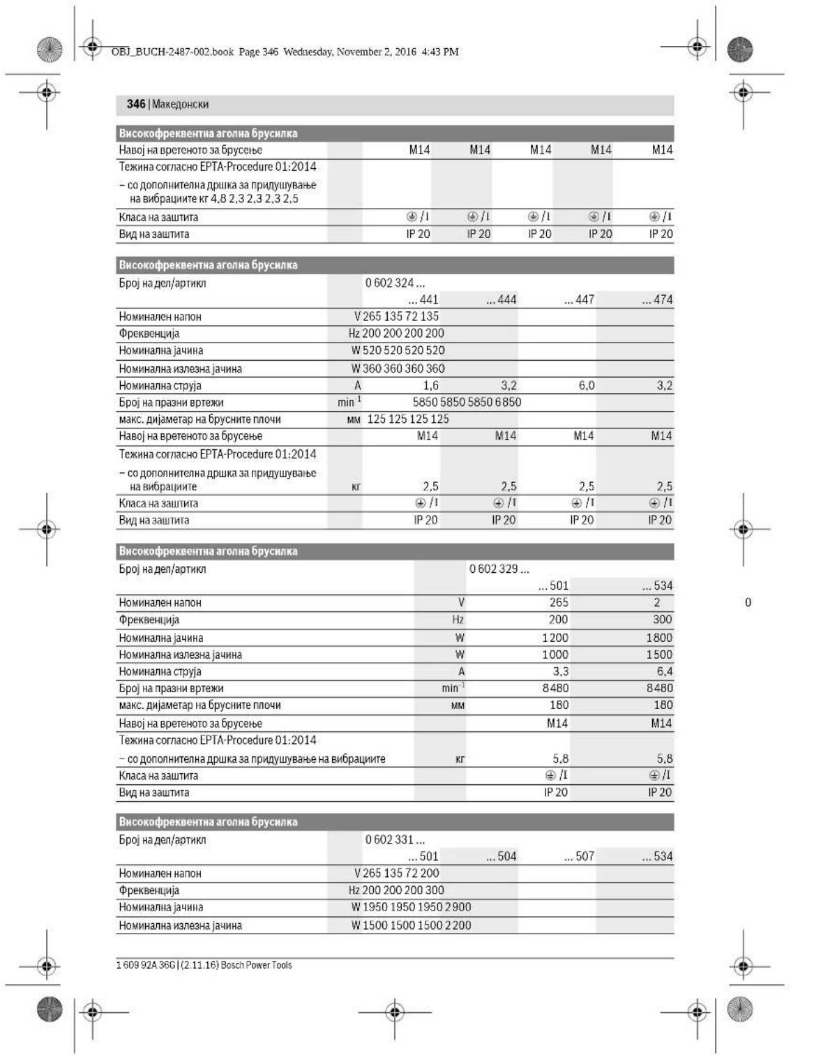
OBI_BUCH-2487-002.book Page 347 Wednesday, November 2, 2016 4:43 PM
MaKeIOnHcKn|347
| Ви这样做�хштейнага aronna 6bychnka | ||||
| HommaHajna stryja | A | 5 | 10 | 18 |
| Бpoj ha npa3n ha bptexn | min1 | 8480 8480 8480 8480 | ||
| маск. disjametap ha 6bpycnhte почи | MM | 180 180 180 180 | ||
| HaboJ ha bpeTeHTo 3a 6bpycebe | M14 M14 M14 M14 | |||
| Текина cornilicho EPTA-Procedure 01:2014 - co доронателна дршиka за рindушваье на вобрашипe | К7,17,17,17,1 | |||
| Клеса ha zaшпета | # / I / I / I | |||
| Вид ha zaшпета | IP 20 | IP 20 | IP 20 | IP 20 |
Bucokopkebentha aorna6pycnka
| Бpoj на并向对接 | 0602332... | |||||
| ...501 | ...504 | ...507 | ...534 | ...511 | ||
| Hominien haron | V | 265 | 135 | 72 | 200 | 72 |
| Ф reproбецima | Hz | 200 | 200 | 200 | 300 | 300 |
| Homina на щуна | W | 1950 | 1950 | 1950 | 2900 | 2900 |
| Homina на щуньша щуна | W | 1500 | 1500 | 1500 | 2200 | 2200 |
| Homina на скриja | A | 5 | 10 | 18 | 10 | 27 |
| Бpoj на пазни вргеля | min-1 | 6600 | 6600 | 6600 | 6600 | 6600 |
| мас. дожамер на брусангп лioчи | MM | 230 | 230 | 230 | 230 | 230 |
| Haboj на ветеното за بрусанe | M14 | M14 | M14 | M14 | M14 | M14 |
| Текиа сord正常使用 EPTA-Procedure 01:2014 - соролитенда ручка за падушевке на висдане | Кr | 7,1 | 7,1 | 7,1 | 7,1 | 7,1 |
| Клеса на зашита | + /1 | + /1 | + /1 | + /1 | + /1 | + /1 |
| Вид на зашита | IP 20 | IP 20 | IP 20 | IP 20 | IP 20 | IP 20 |
Accessories for the angle grinder
| Бpoj на颇ten/артык | 0 602 334 ... ...501 ...504 ...507 ...534 |
| Hominahen hanoi | V 265 135 72 200 |
| Фразбениja | Hz 200 200 200 300 |
| Hominahina jaunha | W 2500 2500 2500 3800 |
| Hominahina hyaeseia jaunha | W 2200 2200 2200 3100 |
| Hominahinaстуяа | A 6,7 13,2 24,7 13,2 |
| Бpoj на пазни вретеки | min¹ 6600 6600 6600 6600 |
| макс. диметер на брусянite пioч | MM 230 230 230 |
| Haboj на розенота збухсан | M14 M14 M14 M14 |
| Текина сорлесно EPTA-Procedure 01:2014 - co polonitello на дршka за пюduшваье на вибрацни | Кr 7,8,7,8,7,8 |
| Класа на зашита | © /I /I /I /I |
| Вид на зашита | IP 20 IP 20 IP 20 IP 20 |
Information on supply with energy
The power tool is operated on a high-frequency system and requires a three-phase current with increased frequency and a special plug.
To achieve this increased frequency, the power tool must be connected to a frequency converter (e.g., from a generator or a power supply unit, page 352).
Bosch Power Tools 1609 92A 36C (2.11.16)

OBI_BUCH-2487-002.book Page 348 Wednesday, November 2, 2016 4:43 PM
348|Macedonian
The vibration emission value is determined in accordance with EN 60745-2-3.
Information on noise/vibration
| 0.60230140. | 0.602301434. | 0.60230440. | 0.60230540. | |
| Hinboto ha 38uk ha ypeodot, oueheto co A, | ||||
| TINHIO H3NECBya | ||||
| Hinbo Ha 38yueh npHIncok | dB(A) | 72 | 82 | 79 |
| Hinbo Ha 38yua jaHina | dB(A) | 83 | 93 | 90 |
| Hechnypnoct K | dB | 3 | 3 | 3 |
| Hocete zauHTa 3a clyXOT | ||||
| Bkyntite bpeiNoCTn Ha BnBpaunu a, | ||||
| (BeKtorpcsk 36oP na TpIte HacOki) | ||||
| Hechnypnoct K pIadEni ce Bo cornaChoct | ||||
| co EN 60745-2-3. | ||||
| PobuHNCko 6pycebe (rpy6o | ||||
| 6pycebe): | ||||
| a1 | m/s2 | - | 5.3 | 5 |
| K | m/s2 | - | 2 | 2 |
| Ponipranbe: | ||||
| a1 | m/s2 | 3 | 3 | - |
| K | m/s2 | 1.5 | 1.5 | - |
| 6pycebe co 6pycen nIcT: | ||||
| a1 | m/s2 | 3 | 3 | - |
| K | m/s2 | 1.5 | 1.5 | - |
| 0 602 306 434 | 0 602 324 40. | 0 602 324 44. | |
| 0 602 324 464 | |||
| 0 602 324 474 | |||
| 0 602 324 434 | |||
| НиматICALS: | |||
| НиматICALS | dB(A) | 82 | 77 |
| НиматICALS | dB(A) | 93 | 88 |
| Héchéneyacht K | dB | 3 | 3 |
| Hocete zaußneta 3a clyxot! | |||
| БукшпITE BrepIJICHTN ha BvIbpaunu a, (BekTopcsk)3bOp Ha trpite HacOKN) HeCmIpyHocT K daDeHN ce BOcorgnachocT co EN 60745-2-3. | |||
| Повшнско 6顺序e (rpy6bpycebe): | |||
| a1 | m/s2 | - | - |
| K | m/s2 | - | - |
| Полигалы: | |||
| a1 | m/s2 | < 2,5 | 4 |
| K | m/s2 | 1,5 | 1,5 |
| Буссени co 6顺序ипст: | |||
| a1 | m/s2 | < 2,5 | 4 |
| K | m/s2 | 1,5 | 1,5 |
| 0.60232950. | 0.6023295340.602329511 | 0.6023315.. | 0.6023325.. | |
| Himato ha 38uk ha ypedot, oceheno co A,Tinucho hnahecyba | ||||
| Hibio ha 38yuen nphtncok | dB(A) | 85 | 87 | 86 |
| Hibio ha 38yuha jaunha | dB(A) | 96 | 98 | 97 |
| Hecnypnoct K | dB | 3 | 3 | 3 |
| Hocere sautnla 3a cnyxot! | ||||
1609 92A 36G| (2.11.16) Bosch Power Tools


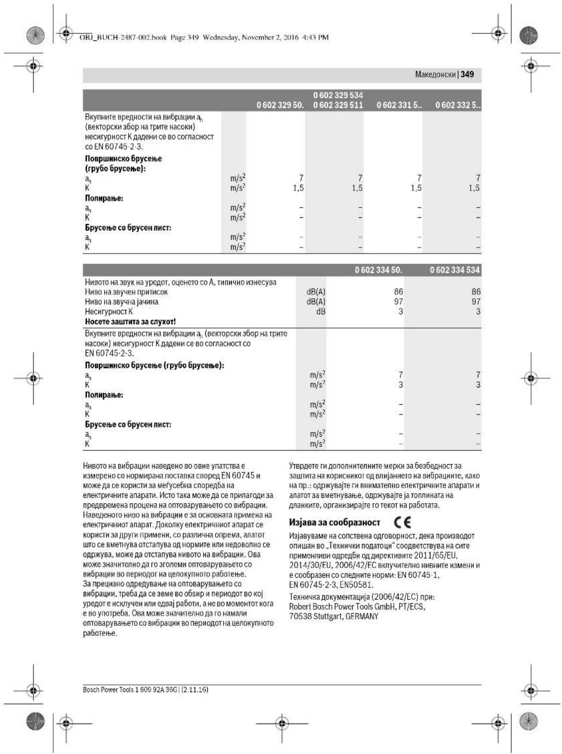
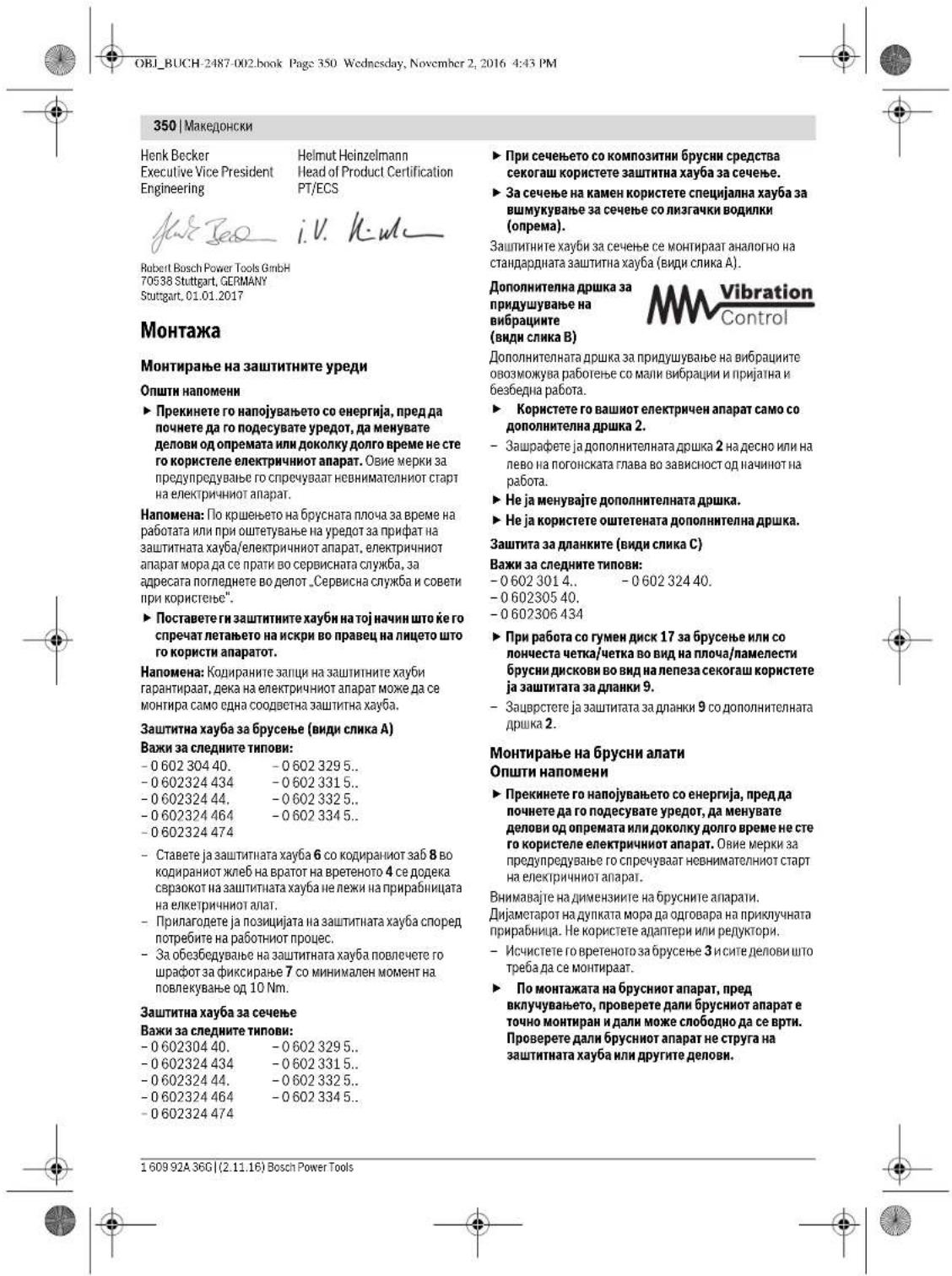
OBI_BUCH-2487-002.book Page 351 Wednesday, November 2, 2016 4:43 PM
Macedonian|351
Mounting the protective devices, suction, and extraction (see figures D1-D2)
Important for the following types:
-060230440. -06023315.. -060232444,..464,-06023325. 474.434 06023345.. -06023295..
- Make sure that the mounting of the spindle (see mounting instructions, page 350) is correct.
- The connecting plate 10 is attached to the spindle for beams 3.
The connecting plate 10 is attached around the central axis of the spindle (see figure). If the spindle is not long enough, the connecting plate 10 must be replaced with a longer one.
- Place the bearing housing 11 (bearing for beams, see figure) on the spindle for beams 3.
- Slide the nut 12 onto the thread of the nut so that the thread, the nut, and the spindle are aligned. - Tighten the nut using the two holes 13, while turning the spindle for beams 3 with the key 14.
Removal
- Remove the spindle for beams 3 with the key 14. Loosen the nut 12 with the two holes 13 from the spindle for beams, while turning the key 14 to hold the spindle.
Electrical device with key for locking the spindle 5
Important for the following types:
-060232440 -0602324434 -060232444.
For the electrical device with key for locking the spindle 5, the locking is done with the key when the device is to be locked (see figure E-12).
To lock the spindle, activate the device only when the spindle for beams is in the operating state. The electrical device can then be removed. - Before use, attach the key to the spindle 5 to lock the spindle for beams 3 with the key. - Mount the bearing housing (see mounting instructions, page 371).
- Remove the keys from the spindle 5 to release the mechanical locking of the spindle for beams.
Mounting the beam on the fence for the beam
(See figure F)
Important for the following types: -06023014. -060232440
-060230540.
H00601806434
Roots
- Make sure to install the protection for early and late potatoes (see, mounting the protective cover, page 350).
- Place the beam for the fence 17 on the fence for the fence 3. Set the beam for the fence 616 by means of the beam for the fence 6. Set the round nut 15 on the thread of the fence. -Do not tighten the round nut completely, but leave a gap of 13, so that the nut 14 can move on the surface of the nut of the fence from the beam 3
CAUTION: The round nut 15 must be fully screwed onto the thread of the beam for the fence, so that it does not turn during operation and the beam is not damaged.
Adjustment
Loosen the thread of the fence for the fence 3 with the nut and the surface of the nut. Adjust the nut 15 with the nut with two holes 13 on the fence for the fence, while with the nut 14 the surface of the nut. -Repeat the procedure for the other beam and the beam for the fence.
Mounting the beam for the fence (see figure G)
Important for the following types:
-06023014. -060232440 -060230540. -0602306434
Roots
CAUTION: The fill level must match the fill level of the rotary valve for brushing (M14).
- Make sure that the protective equipment and additional equipment are mounted (see Mounting the protective equipment, page 350). Turn the rotary valve for brushing 3 with the hex key 18 until the flat surface of the rotary valve hub is aligned with the convex key 14, then tighten the screw on the surface of the rotary valve hub.

352 | Macedonian
Removal
Turn the rotary valve for brushing 3 with the hex key 18 until the flat surface of the rotary valve hub is aligned with the convex key 14, then tighten the screw on the surface of the rotary valve hub.
Mounting the chain kit (see Figure H)
Important for the following types:
-060230440. -06023315..
-060232444...464 -06023325.
474.434 -06023345.
-06023295.
Use
CAUTION: The fill level of the chain kit must match the fill level of the rotary valve for brushing (M14). - Make sure that the protective equipment and additional equipment are mounted (see Mounting the protective equipment, page 350). Turn the chain kit 19 (chain or sprocket) on the rotary valve for brushing 3 until the flat surface of the rotary valve hub is aligned with the convex key 14, then tighten the screw on the surface of the rotary valve hub.
Removal
Turn the chain kit 19 with the convex key on the surface of the rotary valve for brushing, until the convex key 14 is aligned with the flat surface of the rotary valve hub.
The material may cause allergic reactions or harm the health of the user if used improperly. The material is not intended for use as a toy.
The material may be carcinogenic, especially in combination with other substances (chromate, rust protection agents). The material may be harmful if swallowed.
Wear appropriate protective gloves and clothing when handling the material. Ensure good ventilation in the work area. Dispose of the material properly. Be careful not to contaminate your skin or eyes with the material.
Clean the work area after use. The tool must not be used by children.
Connection to power supply
Electrical appliances must be connected to a power supply that provides the correct voltage and frequency as specified on the rating plate.
The power supply voltage varies in different regions, with different frequencies, and may have different ratings. The choice of power supply depends on the electrical appliance that needs to be connected. Consult a qualified electrician when selecting the appropriate power supply.
The electrical appliance must be connected to a suitable power outlet. To connect to the power supply, the plug must be inserted into a properly grounded outlet (with a protective earth contact).
The electrical appliance may be equipped with a residual current device (RCD) for protection against electric shock. The RCD must have a rated residual current of 30 mA or less. The RCD must be installed by a qualified electrician.
For your safety, read the safety instructions and the installation manual before installing the RCD!
Connecting the power cord (see figures 11-12)
Remove the cover of the terminal box 22. Loosen the screw of the cable gland 12. Insert the power cord 24 through the cable gland 12. Connect the wires of the power cord to the terminals of the electrical appliance according to the wiring diagram. Tighten the cable gland 12. Replace the cover of the terminal box 22. Connect the protective earth wire to the terminal marked with the earth symbol.
Connect the phase wire L2 to the terminal marked L2.
Connect the neutral wire L3 to the terminal marked L3.
Repeat the procedure for connecting the appliance to the mains supply (see "Connecting to the mains supply", page 21), then switch on the appliance. - The appliance must be connected to a socket with a protective earth contact. - Repeat the procedure for connecting to the mains supply (see "Connecting to the mains supply", page 21) and switch on the appliance. - Finally, check that the protective earth connection is correct.



Macedonian 353
You can now connect the frequency converter to the mains supply.
To connect the frequency converter to the mains supply, follow the instructions in the section on connecting the frequency converter to the mains supply.
Finally, check the correct time!
Checking the correct time
The time of the timer for switching on must correspond to the markings for the clock on the electrical appliance.
If the timer for switching on is not set correctly when the appliance is first used, [see] "Switching on/off the electrical appliance", page 353), you must switch off the electrical appliance and disconnect it from the mains supply.
Open the two covers 22, then remove the connector for connection 21 from the socket and the connector 24. - Insert the metal rods of the coffee machine into the contact openings. - Place the metal rod of the coffee machine into the contact opening L1 and the metal rod of the coffee machine into the contact opening L3. - Repeat the procedure for connecting the connector 23 to the socket for connection 23, then switch on the appliance. Repeat the procedure for connecting the connector 21 to the socket and the connector 24, then close the two covers 22. Finally, check that the protective earth connection is correct. - Switch on the electrical appliance and disconnect it from the mains supply.
Use
Putting into use
The frequency converter must be installed according to the specifications on the rating plate of the electrical appliance. Check the timer for switching on. The timer for switching on must be installed securely and must be able to turn freely. Perform a test of the maximum time of 1 minute without using the appliance on the material. Do not use the timer for switching on if it is damaged or defective. The timer for switching on may be damaged and cause injury. Place the switch for switching on/off 1 in the off position, so that the electrical appliance cannot start working, then place the switch for switching on/off 8 in the on position. This will prevent accidental starting of the device. Check the connection to the mains supply (see "Connecting to the mains supply", page 352), before switching on the electrical appliance again.
Always connect the electrical appliance to the frequency converter first, before connecting the frequency converter to the mains supply.
Before first use, plug the device into the electrical outlet.
Switching on/off the device
Always switch off the device before plugging it into the electrical outlet.
For this, follow the operating instructions or the device manual.
Switching on/off the electrical device with the On/Off switch (see figure J1)
Important for the following steps:
-06023244.
To switch on the electrical device, press the On/Off switch 1. To switch off, press the On/Off switch 1 again. If the device is not in use, switch it off.
Switching on/off the electrical device with the On/Off switch (see figure J2)
Important for the following steps:
-06023014. -06023295.. -060230440. -06023315.. -060230540. -06023325.. -0602306434 -06023345..
To put the electrical device into operation, press the On/Off switch 1 and hold it down. To lock the On/Off switch 1, press the lock button. To unlock, press the On/Off switch 1 again. As long as it is locked, keep pressing the On/Off switch 1 and then release it.
Advice for operation
Charge the battery before using the device for the first time, before replacing the battery, or after a long period of non-use. These measures ensure the proper functioning of the electrical device. Pay attention to the safety instructions in the manual.
Bosch Power Tools 1609 92A 36C (2.11.16)

The voltage must be measured at the brush ends. If the measured value is not within the specified range (see technical data), the device must be sent to the Bosch after-sales service for repair. If the specified value is exceeded, the brushes may be damaged, and if the value is below, the device will not operate properly. Use only original cables! Before each use, check the device, cable, and plug. The cable and plug must not be damaged; if they are, they must be replaced to avoid danger. Repairs should only be carried out by qualified personnel. Only in this way can the safety of the device be ensured.
Disconnect the plug from the power source and remove the brushes from the device and the brush holders from the connectors. Then connect the device to the power supply.
After the first 150 operating hours, clean the device with a soft brush. Then refill the lubricant and use the correct type of oil. If the device is damaged, clean it with a special Bosch oil. After about 300 operating hours, the device should be serviced.
The Bosch after-sales service will quickly and reliably perform the repair. If a replacement cable is needed, contact Bosch or an authorized Bosch dealer for electric tools to ensure safety. Dispose of and store the device with care.
Accessories
For the complete accessory program, you can find information on the Internet at www.bosch-pt.com and www.boschproductiontools.com, as well as from your specialized dealer.
After-sales service and advice on use
The after-sales service will answer your questions regarding repairs and maintenance of your product as well as spare parts. You can find exploded views and information on spare parts at: www.bosch-pt.com. The Bosch application consulting team will be happy to help you if you have questions about our products. For all spare parts and warranty claims, please contact the after-sales service using the phone number listed on the warranty card.
Macedonia
A.D. Elektrik Caba, Kovačević 47b, no. 3, 1000 Skopje, email: dimce.dimcev@servis-bosch.mk, http://www.servis-bosch.mk, Tel./Fax: 02/2467610, Mobile: 070595888
Disposal
Electric tools, accessories, and packaging should be recycled in an environmentally friendly manner. Do not dispose of electric tools in household waste.
Only for EU countries
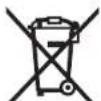
According to the European Directive 2012/19/EU on waste electrical and electronic equipment and its implementation in national law, electric tools that are no longer usable must be collected separately and recycled in an environmentally friendly manner.
Serbian
Safety Instructions
General Power Tool Safety Warnings
WARNING Read all safety warnings and all instructions. Failure to follow the warnings and instructions may result in electric shock, fire and/or serious injury. Save all warnings and instructions for future reference.
The term "power tool" in the warnings refers to your mains-operated (corded) power tool or battery-operated (cordless) power tool.
Work Area Safety
Keep work area clean and well lit. Cluttered or dark areas invite accidents. Do not operate power tools in explosive atmospheres, such as in the presence of flammable liquids, gases or dust. Power tools create sparks which may ignite the dust or fumes. Keep children and bystanders away while operating a power tool. Distractions can cause you to lose control.
Electrical Safety
Power tool plugs must match the outlet. Never modify the plug in any way. Do not use any adapter plugs with earthed (grounded) power tools.


356 | Serbian
Unmodified plugs and matching outlets will reduce risk of electric shock.
Avoid body contact with earthed or grounded surfaces, such as pipes, radiators, ranges and refrigerators. There is an increased risk of electric shock if your body is earthed or grounded. Do not expose power tools to rain or wet conditions. Water entering a power tool will increase the risk of electric shock. Do not abuse the cord. Never use the cord for carrying, pulling or unplugging the power tool. Keep cord away from heat, oil, sharp edges or moving parts. Damaged or entangled cords increase the risk of electric shock. When operating a power tool outdoors, use an extension cord suitable for outdoor use. Use of a cord suitable for outdoor use reduces the risk of electric shock. If operating a power tool in a damp location is unavoidable, use a residual current device (RCD) protected supply. Use of an RCD reduces the risk of electric shock.
Personal Safety
Be careful, watch what you are doing and work sensibly with your power tool. Do not use the power tool if you are tired or under the influence of drugs, alcohol, or medication. A moment of inattention when using a power tool can lead to serious injuries. Wear personal protective equipment and always wear safety glasses. Wearing personal protective equipment, such as a dust mask, non-slip safety shoes, a safety helmet, or hearing protection, depending on the type and use of the power tool, reduces the risk of injury. Avoid unintentional starting. Make sure the power tool is switched off before connecting it to the power supply and/or battery, picking it up, or carrying it. If you carry the power tool with your finger on the switch or connect it to the power supply while it is switched on, this can lead to accidents. Remove adjusting tools or wrenches before switching on the power tool. A tool or wrench left attached to a rotating part of the device can lead to accidents. Avoid abnormal body posture. Always make sure you stand firmly and maintain your balance at all times. This way you can better control the power tool in unexpected situations. Wear suitable clothing. Do not wear loose clothing or jewelry. Keep your hair, clothing, and gloves away from moving parts. Loose clothing, long hair, or jewelry can be caught by rotating parts. If dust extraction and collection devices can be mounted, make sure they are properly connected and used. Using dust extraction can reduce dust-related hazards.
Careful use and handling of power tools
Before using the device, read the instructions. Use the electric tool designated for your work. With the appropriate electric tool, you work better and more safely in the specified work area. Do not use any electric tool whose switch is defective. Electric tools that cannot be turned on or off are dangerous and must be repaired. Pull the plug out of the socket and/or remove the battery before making adjustments to the device, changing accessory parts, or storing the device. This precaution prevents unintentional starting of the electric tool. Keep unused electric tools out of the reach of children. Do not allow use of the device by persons who do not know the device or have not read these instructions. Electric tools are dangerous when used by inexperienced persons. Carefully maintain the electric tool. Check whether the moving parts of the device function safely and do not jam, whether parts are broken or damaged in any way that affects the function of the electric tool. Repair these damaged parts before use. Many accidents have their causes in poorly maintained electric tools. Keep cutting tools sharp and clean. Carefully maintained cutting tools with sharp edges are less likely to jam and are easier to control. Use the electric tool, accessories, inserted tools, etc. according to these instructions. Pay attention to the working conditions and the job to be done. Using electric tools for purposes other than those intended can lead to dangerous situations.
Service
Have your electric tool repaired only by qualified personnel and only with original spare parts. This ensures that the safety of the device is maintained.
Serbian | 363
| Visokofrekventna ugaona brusilica | |||||
| Vrsta zašite | IP 20 | IP 20 | IP 20 | IP 20 | |
| Napomene o napajanju Elektrichi nireedaj je deo visokofrekventnog systema i zahteva trofaznu naizmeničnu struju sa frekvencijom koja odgovara oznaci na pločici uredaja. | |||||
| Informacije o šumovima/vibracijama Vrednosti emisije šumova se odreduji u skladu sa EN 60745-2-3. | |||||
| 0 602 301 40. | 0 602 301 434 | 0 602 304 40. | 0 602 305 40. | ||
| A-vrednovan nivo šumova uredjaja iznosi tipićno Nivo zbućnog pritiska dB(A) | 72 | 82 | 79 | 76 | |
| Nivo snage vžuka dB(A) | 83 | 93 | 90 | 87 | |
| Nesigurnost K dB | 3 | 3 | 3 | 3 | |
| Nosite zašitu za sluh! Ukupne vrednosti vibracija a, (zbir vektora tri pracva) i nasigurnost K su dobujeni prema EN 60745-2-3. | |||||
| Brušanje povrsina (gruba obrada): | |||||
| a, m/s2 | - | 5,3 | 5 | - | |
| K m/s2 | - | 2 | 2 | - | |
| Poliranje: | |||||
| a, m/s2 | 3 | 3 | - | < 2,5 | |
| K m/s2 | 1,5 | 1,5 | - | 1,5 | |
| Brušanje sa brusnim listom: | |||||
| a, m/s2 | 3 | 3 | - | < 2,5 | |
| K m/s2 | 1,5 | 1,5 | - | 1,5 | |
| 0 602 306 434 | 0 602 324 40. | 0 602 324 44.0 0 602 324 44.0 0 602 324 44.0 0 602 324 44.0 0 602 324 44.0 0 602 324 44.0 0 602 324 44.0 0 602 324 | 0 602 324 44.0 0 602 324 44.0 0 602 324 44.0 0 602 324 44.0 0 602 324 44.0 0 602 324 44.0 0 602 32 | ||
| A-vrednovan nivo šumova uredjaja iznosi tipićno Nivo zbućnog pritiska dB(A) | 82 | 77 | 82 | ||
| Nivo snage vžuka dB(A) | 93 | 88 | 93 | ||
| Nesigurnost K dB | 3 | 3 | 3 | ||
| Nosite zašitu za sluh! | |||||
| Ukupne vrednosti vibracija a, (zbir vektora tri pracva) i nasigurnost K su dobujeni prema EN 60745-2-3. | |||||
| Brušanje povrsina (gruba obrada): | |||||
| a, m/s2 | - | - | 6 | ||
| K m/s2 | - | - | 2 | ||
| Poliranje: | |||||
| a, m/s2 | < 2,5 | 4 | - | ||
| K m/s2 | 1,5 | 1,5 | - | ||
| Brušanje sa brusnim listom: | |||||
| a, m/s2 | < 2,5 | 4 | - | ||
| K m/s2 | 1,5 | 1,5 | - | ||
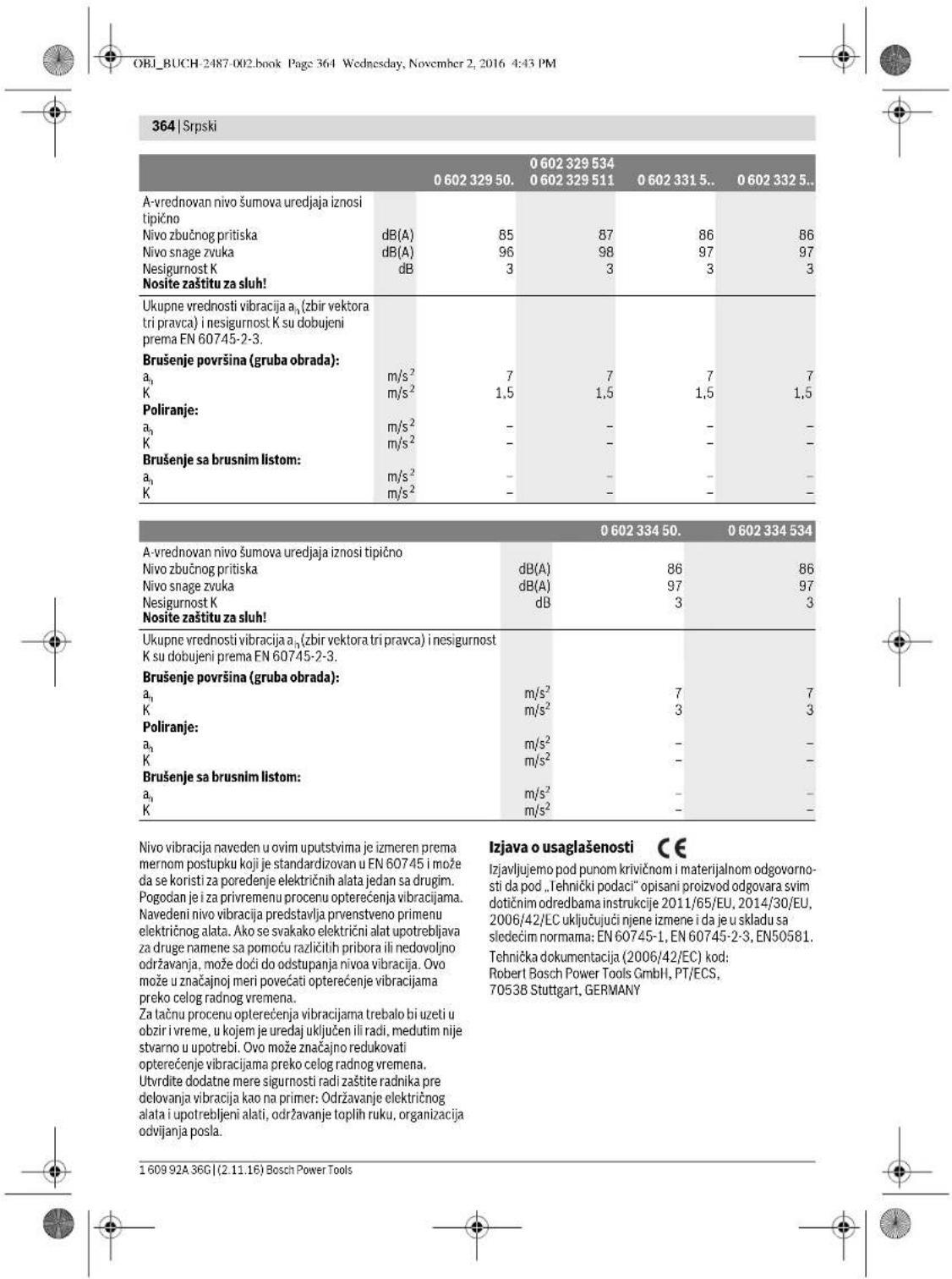
Serbian 365
Henk Becker
Executive Vice President Engineering
Heimut Heinzelmann
Head of Product Certification PT/ECS

Robert Bosch Power Tools GmbH
70538 Stuttgart, GERMANY
366 | Serbian
In accordance with the regulations, place the required abrasive tool (grinding disc, cutting disc, or roughing disc) onto the grinding spindle 3. Place the clamping nut 12 onto the spindle thread so that the middle of the clamping nut points upward. Tighten the clamping nut firmly using the two-pin wrench 13, while holding the spindle surface with the fork wrench 14 in the opposite direction.
Removal
- Hold the grinding spindle 3 on the spindle surface with the fork wrench 14.
- Unscrew the clamping nut 12 using the two-pin wrench 13, while holding the spindle surface with the fork wrench 14 in the opposite direction. Then pull the abrasive tool and the receiving flange off the grinding spindle.
Power tools with spindle lock button 5
The following types apply:
-060232440. -0602324434 -060232444.
For power tools with spindle lock button 5, when mounting abrasive tools, hold the spindle with the fork wrench (see figures E1-E2).
Activate the spindle lock button only when the grinding spindle is at a standstill. Otherwise, the power tool may be damaged. Before starting the grinder, press the spindle lock button 5 to lock the grinding spindle 3, and keep the button pressed. Mount the required abrasive tool (see "Mounting grinding discs, cutting discs, or roughing discs", page 365). Release the spindle lock button 5 to unlock the grinding spindle.
Mounting the rubber sanding pad (see figure F)
The following types apply:
-06023014. -060232440 -060230540. -0602306434
Insertion
- Make sure that the hand guards and auxiliary handle are mounted (see "Mounting protective devices", page 365). Place the rubber sanding pad 17 onto the grinding spindle 3.
- Place the sanding sheet 16 onto the rubber sanding pad.
- Place the round nut 15 onto the spindle thread. Tightly screw the round nut using the pin wrench 13d, while holding the surface of the spindle wrench 3 in the opposite direction with the open-end wrench 14.
Make sure that the round nut 15 is fully screwed on and the rubber sanding pad is compressed, so that it does not interfere during sanding and the sandpaper is fixed.
Removal
Hold the sanding spindle 3 firmly on the wrench surface using the open-end wrench 14. - Unscrew the round nut 15 from the sanding spindle using the pin wrench 13, while holding the wrench surface in the opposite direction with the open-end wrench 14. - Pull the sandpaper and the rubber sanding pad off the sanding spindle.
Installation (see figure G)
Applies to the following types:
Slovenian 377
| Visokofrekvenčni kotni brusilnik | ||||
| Zašćitni razred | ©/I/I/I/I | © | © | © |
| Vrsta zašće | IP 20 | IP 20 | IP 20 | IP 20 |
Warnings for power supply
The power tool is part of a high-frequency system and requires 3-phase current with a frequency according to the specifications on the rating plate.
To achieve the specified frequency, you must connect the power tool to a frequency converter (see "Connection to power supply", page 381).
378 | Slovenian
| 0 602 329 50. | 0 602 329 534 | 0 602 331 5.. | 0 602 332 5.. | ||
| 0 602 329 511 | |||||
| Nivo hrupa naprave po vrednotenju Āznaša tipićno | |||||
| Nivo zvočnega tlaka | dB(A) | 85 | 87 | 86 | 86 |
| Nivo jakosti zvoka | dB(A) | 96 | 98 | 97 | 97 |
| Netočnost K | dB | 3 | 3 | 3 | 3 |
| Nosite zaščitne glušnike! | |||||
| Skupne vrednosti vibracij ān (vektorska vsota treh smeri) in negotovost K se izraču-najo v skladu z EN 60745-2-3. | |||||
| Bruşanje prevlek (kosmačanje): | |||||
| a1 | m/s2 | 7 | 7 | 7 | 7 |
| K | m/s2 | 1,5 | 1,5 | 1,5 | 1,5 |
| Poliranje: | |||||
| a1 | m/s2 | - | - | - | - |
| K | m/s2 | - | - | - | - |
| Bruşanje z brusilnim listom: | |||||
| a1 | m/s2 | - | - | - | - |
| K | m/s2 | - | - | - | - |
| 0 602 334 50. | 0 602 334 534 | ||
| Nivo hrupa naprave po vrednotenju A znaša tipično | |||
| Nivo zvočnegа tlaka | dB(A) | 86 | 86 |
| Nivo jakosti zvoka | dB(A) | 97 | 97 |
| Netočnost K | dB | 3 | 3 |
| Nosite zašcitne glušnike! | |||
| Skupne vrednosti vibracij a1 (vektorska vsota treh smeri) in negotovost K se izračunaj v skladu z EN 60745-2-3. | |||
| Bruşanje prevlek (kosmačanje): | |||
| a1 | m/s2 | 7 | 7 |
| K | m/s2 | 3 | 3 |
| Poliranje: | |||
| a1 | m/s2 | - | - |
| K | m/s2 | - | - |
| Bruşanje z brusilnim listom: | |||
| a1 | m/s2 | - | - |
| K | m/s2 | - | - |
Slovenian 379
Henk Becker
Executive Vice President Engineering
Heimut Heinzelmann
Head of Product Certification PT/ECS

Robert Bosch Power Tools GmbH
70538 Stuttgart, GERMANY Stuttgart, 01.01.2017
Assembly
Mounting the protective devices
General instructions
Before adjusting the device, replacing accessory parts, or storing the power tool, you must disconnect the power supply. This precaution prevents unintentional starting of the power tool.
Warning: If the grinding wheel breaks during operation or if the protective cover on the power tool is damaged, you must immediately send the power tool to the service address; the addresses can be found in the section "Service and advice on use".
Adjust the protective cover so that sparks are prevented from flying in the direction of the operator.
Switching the power tool on/off
with a safety slide switch (see Figure J1)
Croatian387

Croatian|391
Notes on electrical power supply
The power tool is part of a high-frequency system and requires three-phase current with a frequency according to the rating plate.
To achieve the frequency, the power tool must be connected to a frequency converter (see Connection to power supply, page 394).
Information on noise and vibration
394|Croatian
Press the spindle lock button only while the grinding spindle is at a standstill. Otherwise, the power tool could be damaged. - Before mounting the grinding tool, press the spindle lock button 5 to lock the grinding spindle 3 and keep the button pressed. - Mount the desired grinding tool (see Mounting the grinding disc, cutting disc, or roughing disc, page 393). - Release the spindle lock button 5 to unlock the grinding spindle.
Mounting the rubber sanding pad (see Figure F)
General safety instructions
WARNING Read all safety warnings and all instructions. Failure to follow the warnings and instructions may result in electric shock, fire and/or serious injury.
Estonian 401
Estonian 405
| 0.60230140. | 0.602301434. | 0.60230440. | 0.60230540. | |
| Vibratsionitase \( a_{\mathrm {p}} \) (kolme telje vektorsum- ma) ja mõötemääramatus K, kindlaks teh- tud kooskolas standardiga EN 60745-2-3. | ||||
| Pinna lihvinmisel: | ||||
| \( a_{\mathrm {n}} \) | \( m/s^{2} \) | - | 5,3 | 5 |
| K | \( m/s^{2} \) | - | 2 | 2 |
| Poleerimisel: | ||||
| \( a_{\mathrm {n}} \) | \( m/s^{2} \) | 3 | 3 | - |
| K | \( m/s^{2} \) | 1,5 | 1,5 | - |
| Lihvaberiga lihvinmisel: | ||||
| \( a_{\mathrm {n}} \) | \( m/s^{2} \) | 3 | 3 | - |
| K | \( m/s^{2} \) | 1,5 | 1,5 | - |
406|Estonian
Henk Becker Helmut Heinzelmann Executive Vice President Head of Product Certification Engineering PT/ECS
iV. k = m
Robert Bosch Power Tools GmbH 70538 Stuttgart, GERMANY Stuttgart, 01.01.2017
Assembly
Estonian 407
408|Estonian
Removal
Estonian 409
410|Estonian
Static guidelines
When cutting grooves into load-bearing walls, follow the guidelines of DIN 1053 Part 1 or the regulations of the respective country. These regulations must be strictly observed. Before starting work, consult a qualified structural engineer, architect, or construction supervisor.
Grinding
Latvian|413
The diameter and thickness of the accessory must match the design and dimensions of the power tool. If the accessory dimensions are chosen incorrectly, it will not seat fully in the guard and will make the tool difficult to control during operation. Accessories fastened by means of a thread must precisely match the thread of the grinder spindle. Accessories fastened by means of a backing flange must have a hole diameter that matches the diameter of the locating boss on the backing flange. Accessories that are not precisely mounted on the power tool spindle will not run true, will vibrate excessively, and can cause loss of control over the power tool. Do not use damaged accessories. Before each use, check the accessories for damage, for example, check that grinding discs are not chipped or cracked, that the backing pad shows no cracks or tears, and that the wires of wire brushes are not loose or broken. If the power tool or an accessory has been dropped from a height, check that it is not damaged, or use an undamaged accessory. After inspecting and installing an accessory, let the power tool run at maximum no-load speed for one minute, holding the rotating accessory at a safe distance from yourself and other persons in the vicinity. Damaged accessories will usually break apart during this test. ▸ Wear personal protective equipment. Depending on the work to be performed, choose a full face shield, safety goggles, or standard safety glasses. As needed, wear a dust mask, hearing protection, and protective gloves to protect against flying fragments of the grinding accessory and the workpiece. The operator's eyes must be protected from flying debris generated during work. A dust mask or respirator must protect the operator's respiratory tract from dust generated during work. Prolonged exposure to high noise levels can cause permanent hearing damage. ▸ Ensure that other persons are at a safe distance from the work area. Anyone entering the work area must wear personal protective equipment. Fragments of the workpiece or of a broken accessory can fly at high speed and cause injury to persons at a considerable distance from the work area. During operation, hold the power tool only by the insulated gripping surfaces, because the accessory may contact hidden wiring or the tool's own power cord. If the accessory contacts a live wire, the voltage will be conducted to the metal parts of the tool and can cause an electric shock to the operator. Keep the rotating accessory away from the power cord. If you lose control of the tool, the accessory may cut the cord or become entangled in it, and any part of your body could come into contact with the rotating accessory.
Do not use the power tool until the working tool has come to a complete stop. The rotating working tool may contact the supporting surface, as a result of which the power tool may become uncontrollable. Do not operate the power tool while it is being carried. The user's clothing or hair may accidentally come into contact with the rotating working tool and become entangled, causing the working tool to come into contact with the user's body. Regularly clean the ventilation openings of the power tool. The air flow drawn in by the motor sucks dust into the tool housing, and a large accumulation of metal dust can cause electric shock. Do not use the power tool in the vicinity of flammable materials. Flying sparks can ignite such materials. Do not use tools that require a cooling liquid. The use of water or other liquid cooling agents can cause electric shock.
Kickback and related warnings
Kickback is a sudden reaction to a pinched or snagged rotating working tool, such as a grinding disc, grinding wheel, wire brush, etc. The pinching or snagging of the rotating working tool causes a sudden stop. As a result, the power tool is propelled in the direction opposite to the rotation of the working tool at the point of the snagging, and often becomes uncontrollable. If, for example, a grinding disc snags or pinches in the workpiece, the edge of the disc that is immersed in the workpiece can catch on the material and cause the disc to climb out or kick back. In such a case, the grinding disc moves toward or away from the user, depending on the direction of rotation of the disc relative to the workpiece. In addition, the grinding disc may break. Kickback is the result of improper or unskillful use of the power tool. It can be avoided by taking certain precautions, which are described below.
Hold the power tool firmly and adopt a body and arm position that best allows you to resist the forces of kickback. Always use the auxiliary handle, if provided, to best compensate for kickback or reactive torque and maintain control of the tool. With proper precautions, the user can effectively resist kickback and reactive torque in any situation. Do not bring your hands near the rotating working tool. In the event of kickback, the working tool may also strike the user's hand. Avoid positioning your body in the area where the power tool may move during a kickback. During kickback, the power tool will be propelled in the direction opposite to the movement of the working tool at the point of snagging. Take special care when working on corners, sharp edges, etc. Do not allow the working tool to bounce off the workpiece or become snagged in it. When contacting corners or sharp edges, the rotating working tool may deflect and jump out of the workpiece or become snagged in it. This can cause loss of control of the power tool or kickback.

Do not use accessories that are damaged. Using such tools may cause the tool to kick back or break, which can lead to injury. Follow the safety instructions for grinding and cutting. Use only grinding tools that are suitable for your power tool and the guard provided for such tools. The guard may not adequately cover unsuitable grinding tools, preventing you from achieving the desired level of safety. Curved grinding wheels must be mounted so that their grinding surface does not protrude beyond the edge of the guard. An improperly mounted grinding wheel that protrudes beyond the edge of the guard cannot be adequately covered. For safety reasons, the guard must be firmly attached to the power tool and adjusted so that the smallest possible portion of the grinding wheel is exposed towards the operator. The guard helps protect the operator from fragments and accidental contact with the grinding wheel, as well as from flying sparks that could cause burns. Grinding tools may only be used for the purpose for which they are intended. For example, never use the side surface of a cutting disc for grinding. Cutting discs are designed for cutting materials with the edge of the disc. Applying strong pressure to the side surface can break the tool. When using a depressed-center grinding wheel, always use an undamaged clamping flange with the correct size and shape. A properly fitting clamping flange supports the grinding wheel securely during operation and reduces the risk of breakage. The clamping flanges used with cutting discs may differ from those used with other types of grinding wheels. Do not use worn grinding wheels that were designed for power tools with higher power. Grinding wheels intended for larger power tools are not suitable for use in smaller power tools, which typically have higher speeds, and they may break during operation.
Additional specific safety instructions for cutting
Do not apply excessive pressure to the cutting disc and do not allow it to jam. Do not make cuts that are too deep. Overloading the cutting disc can cause it to bind or jam in the cut, which increases the risk of kickback or tool breakage. Avoid being in front of or behind the rotating cutting disc. If during operation the operator moves the cutting disc away from himself in the direction of the workpiece, in the event of kickback, the power tool with the rotating cutting disc may be thrown directly towards the operator. When interrupting work or if the cutting disc jams, switch off the power tool and hold it still until the cutting disc has completely stopped. Do not attempt to pull a still rotating cutting disc out of the cut, as this may cause kickback. Investigate and eliminate the cause of the disc jamming.
Do not switch the power tool on again if the inserted tool is still in the cut. After switching on, wait until the tool reaches full cutting speed, and only then carefully continue cutting. Otherwise, the cutting disc may catch in the cut and be thrown out, which can also cause kickback. To reduce the risk of kickback when the cutting disc jams, support the workpiece sheet or large workpieces. Large workpieces may bend under their own weight. The workpiece must be supported on both sides—near the cut and at the edge of the workpiece. Observe special caution when making plunge cuts in walls or other areas that cannot be seen from both sides. When plunging the cutting disc into the material, it may come into contact with gas pipes, water pipes, electrical lines, or other objects, which in turn can cause kickback and/or lead to injury.
Special safety instructions for sanding with sandpaper sheets: Do not use oversized sanding sheets. Choose sanding sheets of the size recommended by the manufacturer. If the sanding sheet extends beyond the edge of the sanding pad, it can cause injury, lead to snagging or tearing of the sheet, or result in kickback.
Special safety instructions for polishing
| Augstkrevnesc lenkslipmasina | ||||
| Maks. slipesanas diska diameters | mm 180 180 180 180 | |||
| Darbvärpstas vitne | M14 M14 M14 M14 | |||
| Svars atbilstoši EPTA-Procedure 01:2014 - ar pretvibracijas papildrokturi | kg 7,1 7,1 7,1 7,1 | |||
| Elektroaizsardžibas klase | ⊕ /1/1/1 | ⊕ | ⊕ | ⊕ |
| Aizsardžibas tips | IP 20 | IP 20 | IP 20 | IP 20 |
High-frequency angle grinder
| Izstradajuma numurs | 0 602 332 ... | |||||
| ... 501 | ... 504 | ... 507 | ... 534 | ... 511 | ||
| Nominálais spriegums | V 265 135 72 200 72 | |||||
| Frekvidence | Hz 200 200 200 300 300 | |||||
| Nominálá patéřejama jauda | W | 1950 | 1950 | 1950 | 2900 | 2900 |
| Nominálá izejas jauda | W | 1500 | 1500 | 1500 | 2200 | 2200 |
| Nominálá stráva | A | 5 | 10 | 18 | 10 | 27 |
| Griešanás atrums brivgaitá | min. -1 | 6600 | 6600 | 6600 | 6600 | 6600 |
| Maks. silpěsanas diska diametris | mm 230 230 230 230 230 | |||||
| Darbvarpastes vitne | M14 | M14 | M14 | M14 | M14 | |
| Svars atbilstósi EPTA-Procedure 01:2014 - ar pretvibrácijas papildrokturi | kg | 7,1 | 7,1 | 7,1 | 7,1 | 7,1 |
| Elektroázsardízas klase | # /T | # /T | # /T | # /T | # /T | |
| Aizsardzibas tips | IP 20 | IP 20 | IP 20 | IP 20 | IP 20 | |
High-frequency angle grinder
| Izsträdajuma numurs | 0 602 334 ... | ||||
| ... 501 | ... 504 | ... 507 | ... 534 | ||
| Nominālais spiregums | V 265 135 | 72 200 | |||
| Frekvence | Hz 200 200 200 300 | ||||
| Nominālā patērējamā jauda | W | 2500 | 2500 | 2500 | 3800 |
| Nominālā izejas jauda | W | 2200 | 2200 | 2200 | 3100 |
| Nominālā strāva | A | 6,7 | 13,2 | 24,7 | 13,2 |
| Griësanās Ātrums brivgaita | min. | 6600 | 6600 | 6600 | 6600 |
| Maks. sīlpēsanas diska diametrs | mm 230 230 230 230 | ||||
| Darbvärpstas vitne | M14 M14 M14 M14 | ||||
| Svars atbilstoši EPTA-Procedure 01:2014 | |||||
| - ar pretvibrăcijas papildrokturi | kg 7,8 7,8 7,8 7,8 | ||||
| Elektroaizsardžibas klase | €/t/1/t/1 | € | € | € | |
| Aizsardžibas tips | IP 20 | IP 20 | IP 20 | IP 20 | |
Instructions for electrical connection
The power tool is part of a high-frequency power supply system. Its operation requires a three-phase AC voltage with a frequency as specified on the rating plate.
To supply the voltage and frequency, the power tool must be connected to a frequency converter (see section "Connecting to the power supply" on page 423).


| 420 | Latviešu | |||||
| 0.602 329 50. | 0.602 329 5340.602 329 511 | 0.602 331 5.. | 0.602 332 5.. | ||
| Kopëjā vibracijas paãtrinãjuma vêrliba a,(vektoru summa trijos virziemos) un izkliedeKir noteikta atbilstoši standartamEN 60745 2-3. | |||||
| Virsmu slipësana (rupjā): | |||||
| a, | m/s2 | 7 | 7 | 7 | 7 |
| K | m/s2 | 1,5 | 1,5 | 1,5 | 1,5 |
| Puleësana: | |||||
| a, | m/s2 | - | - | - | - |
| K | m/s2 | - | - | - | - |
| Slipësana ar sliploksni: | |||||
| a, | m/s2 | - | - | - | - |
| K | m/s2 | - | - | - | - |
| 0 602 334 50. | 0 602 334 534 | ||
| Instrumenta radità pèc raksturliknes A izsvertà trokëna parametr tipiskës vertibas ir sădas: | |||
| skanas spiiedena limenis | dB(A) | 86 | 86 |
| skanas jaudas limenis | dB(A) | 97 | 97 |
| merijumu izkliede K | dB | 3 | 3 |
| Nësajiet ausu aizsargus! | |||
| Kopejã vibraciçias paàtrinajuma vertiba a, (vektoru summa trijos virziños) un izkliede K ir noteikta atbilostoï standartam EN 60745-2-3. | |||
| Virsmu slipësana (rupjã): | |||
| a1 | m/s2 | 7 | 7 |
| K | m/s2 | 3 | 3 |
| Pulešana: | |||
| a1 | m/s2 | - | - |
| K | m/s2 | - | - |
| Slipësana ar sliploksni: | |||
| a1 | m/s2 | - | - |
| K | m/s2 | - | - |
The vibration level specified in these instructions has been measured in accordance with the procedure specified in standard EN 60745 and can be used for comparing power tools. It can also be used for a preliminary assessment of the additional load caused by vibration.
The vibration level specified here applies to the main uses of the power tool. If the power tool is used for other applications, with different accessories or different application tools, or if it is not maintained sufficiently, the vibration level may differ from the value specified here. This can significantly increase the vibration exposure over the total working period.
To accurately estimate the vibration exposure over a given working period, also consider the times when the power tool is switched off or running but not actually being used for the intended work. This can significantly reduce the vibration exposure over the total working period. Take additional safety measures to protect the operator from the effects of vibration, such as servicing the power tool and application tools in a timely manner, keeping hands warm, and organizing work processes properly.
Executive Vice President Engineering
Helmut Heinzelmann
Head of Product Certification PI/ECS
Robert Bosch Power Tools GmbH
70538 Stuttgart, GERMANY
Stuttgart, 01.01.2017
1609 92A 36G| (2.11.16) Bosch Power Tools


Assembly
Attaching the protective devices
General instructions
Before adjusting the tool, changing accessories, or storing the tool, disconnect it from the power supply. This precautionary measure prevents accidental starting of the power tool.
Note: If during operation the grinding disk or the fastening device on the guard or on the power tool is damaged, the power tool must be sent immediately to a service center, the address of which can be found in the section "Customer service and usage consultation".
Mount the guard so that the spark stream does not point toward the operator.
Note: The guard with the limiting device allows only a specific guard suitable for this power tool to be mounted on the power tool.
Grinding guard (figure A)
For tools:
-060230440, -06023295, -0602324434, -06023315, -060232444, -06023325, -0602324464, -06023345, -0602324474. Insert the guard 6 with the limiting device 8 into the working spindle until the guard rests against the tool flange. Press the guard against the tool flange. Rotate the guard to the position that corresponds to the type of work to be performed. To secure the guard, tighten the fastening screw 7 with a torque of at least 10 Nm.
Cutting guard
For tools:
-060230440, -06023295, -0602324434, -06023315, -060232444, -06023325, -0602324464, -06023345, -0602324474
When cutting with grinding tools whose insert is made of composite materials, always use the cutting guard. When cutting stone, mount the cutting guard with a guide for stone cutting and a dust extraction hood (accessory) on the power tool.
The cutting guard is mounted on the power tool in the same way as the standard guard (figure A).
Auxiliary handle with vibration damping (figure B)
Using the auxiliary handle with vibration damping significantly reduces the harmful effects of vibration, allowing safe and highly productive work. Use the power tool only when the auxiliary handle 2 is mounted.
- Depending on the type of work to be performed, screw the auxiliary handle 2 into the right or left side of the gearbox head. No modifications to the auxiliary handle construction are allowed. Stop using the auxiliary handle if it is damaged.
Hand guard (figure C)
For tools:
-0.6023014 -0.60232440 -0.60230540 -0602306434
When working with a rubber sanding pad 17, as well as cup/disc brushes or segmental sanding discs, always mount the hand guard 9 on the tool.
The hand guard 9 is mounted together with the auxiliary handle 2.
Mounting the sanding tools General instructions
Before adjusting, changing accessories, or storing the tool, disconnect it from the power supply. Such precautionary measures prevent accidental starting of the power tool. Use sanding tools of suitable size. The diameter of the central hole in the disc must match the dimensions of the backing pad. Do not use adapters or auxiliary devices to adjust the size. Clean the spindle 3 and other mounting parts. After mounting the sanding tool and before switching on the power tool, check that the tool is correctly mounted and can rotate freely. Make sure that the sanding tool does not touch the guard or other parts of the power tool.
Mounting sanding, cutting, and rough sanding discs (figures D1 - D2)
For tools:
-060230440. -06023315.. -060232444,..464 -06023325. 474,434 -06023345..
-06023295
Mounting
- Ensure that the appropriate guard is mounted on the tool (see section 'Mounting the guard' on page 421).
- Place the backing pad 10 onto the spindle 3 of the sander.
The backing pad 10 must have a plastic part (ring-shaped insert) that covers the hole. If the ring-shaped insert is missing or damaged, replace it before placing the backing pad 10. Place the selected sanding tool 11 (sanding, cutting, or rough sanding disc) onto the spindle 3, taking into account the direction of rotation of the spindle.


- Place the clamping nut 12 on the spindle thread so that the central recess faces upward.
- Tighten the clamping nut firmly with the two-pin spanner 13, while simultaneously placing the open-end spanner 14 on the spindle lock nut and using it to hold the spindle 3 stationary.
Removal
- Hold the grinder spindle 3 firmly with the open-end spanner 14 placed on the spindle lock nut.
- Unscrew the clamping nut 12 from the grinder spindle with the two-pin spanner 13, while simultaneously holding the grinder spindle with the open-end spanner 14 placed on its lock nut. Then remove the grinding tool and the support flange from the grinder spindle.
Power tools with spindle lock button 5
For tools:
-060232440. -0602324434 -060232444
When using power tools with spindle lock button 5, the grinding tool does not need to be held stationary with the open-end spanner during mounting (see figures E1-E2).
Press the spindle lock button only when the power tool spindle is not rotating. Otherwise, the power tool may be damaged. Before mounting the grinding tool, press the spindle lock button 5 to lock the spindle 3, and keep the button pressed. - Mount the grinding tool to be used (see section "Mounting grinding, cutting, and roughing discs" on page 421). To release the spindle, release the spindle lock button 5.
Mounting the rubber sanding pad (figure F)
For tools:
-06023014. -060232440 -060230540. -0602306434
- Make sure that the protective guard and auxiliary handle are securely attached to the tool (see section "Installing/Removing Protective Devices" on page 421).
- Place the rubber sanding pad 17 onto the sanding spindle 3.
- Place the sanding disc 16 onto the rubber sanding pad.
- Screw the round nut 15 onto the sanding spindle. Tighten the round nut firmly with the two-pin wrench 13, while placing the open-end wrench 14 on the flats of the sanding spindle 3 and holding the spindle with it.
Make sure that the round nut 15, after being tightened, fits properly into the recess of the rubber sanding pad, does not obstruct the sanding process, and firmly holds the sanding disc.
Removal
Hold the sanding spindle 3 firmly with the open-end wrench 14 placed on the spindle flats. - Unscrew the round nut 15 from the sanding spindle with the two-pin wrench 13, while holding the sanding spindle with the open-end wrench 14 placed on its flats. - Then remove the sanding disc and the rubber sanding pad from the sanding spindle.
Mounting the polishing fleece disc (figure G)
For tools:
-06023014. -060232440 -060230540. -0602306434
Mounting
Make sure that the polishing fleece disc fits precisely onto the sanding spindle thread (M14).
Make sure that the protective guard and auxiliary handle are securely attached to the tool (see section "Installing/Removing Protective Devices" on page 421). Screw the polishing fleece disc 18 onto the sanding spindle 3 until it is firmly seated against the spindle flats, while holding the spindle steady with the open-end wrench 14 placed on the spindle flats.
Removal
Unscrew the tightly screwed-on polishing cloth 18 from the grinder spindle with the open-end wrench 14, which is placed on the grinder spindle's holding plate.
Mounting the wire brush (figure H)
Tools:
-060230440. -06023315.. -060232444,...464, -06023325.. ...474,..434 -06023345. -06023295.
Mounting
Make sure that the thread of the wire brush exactly matches the thread of the grinder spindle (M14).
Ensure that the tool is equipped with the protective guard and auxiliary handle (see section "Mounting the protective devices" on page 421). Screw the desired wire brush or cup brush onto the grinder spindle 3 until it firmly seats against the grinder spindle's holding plate, while simultaneously holding the spindle stationary with the open-end wrench 14, which is placed on the grinder spindle's holding plate.



Latvian|423
Removal
- Unscrew the tightly screwed-on wire brush 19 from the grinder spindle with the open-end wrench 14, which is placed on the grinder spindle's holding plate.
Dust and chip extraction
Dust from certain materials, such as lead-containing paint, some types of wood, minerals, and metals, can be harmful to health. Contact with or inhalation of such dust can cause allergic reactions and respiratory diseases in the power tool user or persons in the vicinity.
Dust from certain materials, such as oak or beech wood dust, can cause cancer, especially when the wood has been treated with chemicals (e.g., chromate or wood preservatives). Asbestos-containing materials may only be processed by persons with special professional training.
- Use the dust extraction system most suitable for the material being processed.
The workplace must be well ventilated.
Accessories
To get a complete overview of the Bosch high-quality accessory range, visit the websites www.boschpt.com and www.boschproductiontools.com or contact your local specialized retailer.
| Aukst dožnio kampinis šlifuoklis | |||||
| Gaminio numeris | 0 602 332 ... | ||||
| ... 501 | ... 504 | ... 507 | ... 534 | ... 511 | |
| Nominaloji Čatampa | V 265 135 72 200 72 | ||||
| Dažnis | Hz 200 200 200 300 300 | ||||
| Nominali naudojamoji galia | W 1950 1950 1950 2900 2900 | ||||
| Nominali atiduodamoji galia | W 1500 1500 1500 2200 2200 | ||||
| Nominaloji srové | A 5 | 10 18 10 27 | |||
| Tušciosios eigos sikiq skiačius | min-1 | 6600 6600 6600 6600 6600 | |||
| Maks. šlifavimo disko skersmuo | mm 230 230 230 230 230 | ||||
| Šlifavimo suklio sriegis | M14 M14 M14 M14 M14 | ||||
| Svoris pagal „EPTA-Procedure 01:2014" - su vibracija slopinancia papildoma rankena | kg | 7,1 | 7,1 | 7,1 | 7,1 |
| Apsaugos klase | /1 | /1 | /1 | /1 | |
| Apsaugos lipas | IP 20 | IP 20 | IP 20 | IP 20 | |
| Aukšto dažnio kampinis šlifuoklis | |||||
| Gaminio numeris | 0 602 334 ... | ||||
| ... 501 | ... 504 | ... 507 | ... 534 | ||
| Nominaloji Ātampa | V | 265 | 135 | 72 | 200 |
| Dažnis | Hz | 200 | 200 | 200 | 300 |
| Nominali naudojamoji galia | W | 2500 | 2500 | 2500 | 3800 |
| Nominali atiduodamoji galia | W | 2200 | 2200 | 2200 | 3100 |
| Nominaloji srové | A | 6,7 | 13,2 | 24,7 | 13,2 |
| Tušciosios eigos sukijski skáčius | min-1 | 6600 | 6600 | 6600 | 6600 |
| Maks. šlifavimo disko skersmuo | mm | 230 | 230 | 230 | 230 |
| Šlifavimo suklio sriegis | M14 | M14 | M14 | M14 | |
| Svoris pagal „EPTA-Procedure 01:2014" - su vibracija slopınancia papildoma rankena | kg | 7,8 | 7,8 | 7,8 | 7,8 |
| Apsaugos klase | ®/I | ®/I | ®/I | ®/I | |
| Apsaugos tipas | IP 20 | IP 20 | IP 20 | IP 20 | |
| 0 602 329 50. | 0 602 329 534 | 0 602 331 5.. | 0 602 332 5.. | ||
| 0 602 329 511 | |||||
| Vibraciños bendroji verte a h (triju krypčiu at-stojamasis vektorius) ir paklaida K nustaty-tos pagal EN 60745-2-3. | |||||
| Paviršiaus šilfavimas (rupusis apdirbimas): | |||||
| a h | m/s2 | 7 | 7 | 7 | 7 |
| K | m/s2 | 1,5 | 1,5 | 1,5 | 1,5 |
| Poliravimas: | |||||
| a h | m/s2 | - | - | - | - |
| K | m/s2 | - | - | - | - |
| Šilfavimas naudojant šilfavimo popieriaus lapeli: | |||||
| a h | m/s2 | - | - | - | - |
| K | m/s2 | - | - | - | - |
Executive Vice President Engineering
Helmut Heinzelmann
Head of Product Certification PT/ECS
Robert Bosch Power Tools GmbH
70538 Stuttgart, GERMANY
Stuttgart, 01.01.2017
436|Lithuanian
Assembly
Lithuanian 437
Removal
- Hold the sanding spindle 3 with a face spanner 14 placed on the spindle flats. Unscrew the clamping nut 12 with the pin spanner 13 from the sanding spindle, while holding the face spanner 14 on the spindle flats. Then remove the sanding tool and the backing pad from the sanding spindle.
Power tool with spindle locking key 5
Applicable to the following types:
-060232440, -0602324434, -060232444
438|Lithuanian
- It is recommended to wear respiratory protection with P2 class filter.
Lithuanian 439
To lock the on/off switch 1, press the front part of the on/off switch 1 down until it locks. - To switch off the power tool, release the on/off switch 1.
To lock the on/off switch 1, briefly press it and then release it.
Switching the power tool on/off
with safety lock (see figure J2)
Only for the following types:
-06023014.. -06023295.. -060230440. -06023315.. -060230540. -06023325.. -0602306434 -06023345..
- To switch on the power tool, push the on/off switch 1 forward so that it clicks into place. To lock the pressed on/off switch 1, push the on/off switch 1 further forward. To switch off the tool, release the on/off switch 1 or, if it is locked, briefly press and release the on/off switch 1.
Working advice
440 | Lithuanian
If you work with several polishing stages, where a polishing tool with a lower grit is used, you must use a separate backing pad for each grit of the polishing tool.
06023244..
1111111111111111 10000000000000000000000000000
.
(J2gJgJIgJ)Jollae
06023295.. -06023014.
-06023315.. -060230440
-06023325.. -060230540.
__SUPPIMER__
06023315.. - 060230440.
-060283202.32444.,...464; -06023345...474,...434
-06023295..
| 0 602 329 5340 602 329 5110 6080083129.8602 332 5.. | ||||||
| ah ∫jlljzijl jlljzijl jlljzijl jlljzijl jlljzijl jlljzijl jlljzijl jlljzijl jlljzijl jlljzijl jlljzijl jlljzijl jlljzijl jlljzijl jlljzijl jlljzijl jlljzijl jlljz8 | ||||||
| 7 | 7 | 7 | 7 | 2u/ρ | ah | |
| 1,5 | 1,5 | 1,5 | 1,5 | 2u/ρ | K | |
| :JLJLJLJLJLJLJLJLJLJLJLJLJLJLJLJLJLJLJLJLJLJLJLJLJLJLJLJLJLJLJLJLJLJLJLJLJLJLJLJLJLJLJLJLJLJLJLJLJLJLJ LJLJLJLJLJLJLJLJLJLJLJLJLJLJLJLJLJLJLJLJLJLJLJLJLJLJLJLJLJLJLJLJLJLJLJLJLJLJLJLJLJLJLJLJLJLJLJLJLJLJ | ah | |||||
| - | - | - | - | 2u/ρ | ah | |
| - | - | - | - | 2u/ρ | K | |
| :JLJLJLJLJLJLJLJLJLJLJLJLJLJLJLJLJLJLJLJLJLJLJLJLJLJLJLJLJLJLJLJLJLJLJLJLJLJLJLJLJLJ LJLJLJLJLJLJLJLJ LJLJLJLJLJLJLJLJLJLJLJLJLJLJLJLJLJLJLJLJLJLJLJLJLJLJLJLJLJLJLJLJLJLJLJLJLJLJLJLJLJLJ LJLJLJLJLJLJLJLJ JLJ LJ LJ LJ LJ LJ LJ LJ LJ LJ LJ LJ LJ LJ LJ LJ LJ LJ LJ LJ LJ LJ LJ LJ LJ LJ LJ LJ LJ LJ LJ LJ LJ LJ LJ LJ LJ LJ LJ LJ LJ LJ LJ LJ LJ LJ LJ LJ LJ LJ LJ I J I J I J I J I J I J I J I J I J I J I J I J I J I J I J I J I J I J I J I J I J I J I J I J I J I J I J I J I J I J I J I J I J I J I J I J I J I J I J I J I J I J I J I J I J I J I J I J I J I J I I J I J I J I J I J I J I J I J I J I J I J I J I J I J I J I J I J I J I J I J I J I J I J I J I J I J I J I J I J I J I J I J I J I J I J I J I J I J I J I J I J I J I J I J I J I J I J I J I J I | ||||||
| 0 602 334 50.0 602 334 534 | |||
| 86 | 86 | (A) بسیل | العاءة الحرفية (A عو) بعسiguالعاء |
| 97 | 97 | (A) بسیل | العاءة الحرفية (A عو) بعسiguالعاء |
| 3 | 3 | (d) بسیل | K üglaill !العاء |
| aIJü/ρah üjünil alqagag aJülqin alqalq alqalq alqalq alqalq alqalq alqalq alqalq alqalq alqalq alqalq alqalq alqalq alqalq alqalq alqalq alqalq alqalq alqalq alqalq alqalq alqalq alqalq alqalq alqalq alqalq alqal q | |||
| 7 | 7 | 2U/ρ | ah |
| 3 | 3 | 2U/ρ | K |
| :ul | |||
| - | - | 2U/ρ | ah |
| - | - | 2U/ρ | K |
| :ul | |||
| - | - | 2U/ρ | ah |
| - | - | 2U/ρ | K |
C
2011/65/EU
2004/108/EC:2016 19
2006/42/EC, 2014/30/EU:2016 2014 20
EN50581, EN60745-2-3, EN60745-1:
2006/42/EC)
Robert Bosch Power Tools GmbH, PT/ECS
70538 Stuttgart, GERMANY
Henk Becker
Senior Vice President
Engineering
Helmut Heinzelmann
Head of Product Certification
PT/ECS
Robert Bosch Power Tools GmbH,
70538 Stuttgart, Germany
Stuttgart, 01.01.2017
EN60745-1
. 1
Therefore, g(x) = -ln(2)/x + 1/x
| 0 602 301 40.0 602 301 4340 602 304 40.0 602 305 40. | ||||||||||
| a_h ∪ ∅ ∪ ∪ ∪ ∪ ∪ ∪ ∪ ∪ ∪ ∪ ∪ ∪ ∪ ∪ ∪ ∪ ∪ ∪ ∪ ∪ ∪ ∪ ∪ ∪ ∪ ∪ ∪ ∪ ∪ ∪ ∪ ∪ ∪ ∪ ∪ ∪ ∪ ∪ ∪ ∪ ∪ ∪ ∪ ∪ ∪ ∪ ∪ ∪ ∪ ∪ ∮ ∪ ∪ ∪ ∪ ∪ ∪ ∪ ∪ ∪ ∪ ∪ ∪ ∪ ∪ ∪ ∪ ∪ ∪ ∪ ∪ ∪ ∪ ∪ ∪ ∪ ∪ ∪ ∪ ∪ ∪ ∪ ∪ ∪ ∪ ∪ ∪ ∪ ∪ ∪ ∪ ∪ ∪ ∪ ∪ ∪ ∪ ∪ ∪ ∪ ∻ ∪ ∪ ∪ ∪ ∪ ∪ ∪ ∪ ∪ ∪ ∪ ∪ ∪ ∪ ∪ ∪ ∪ ∪ ∪ ∪ ∪ ∪ ∪ ∪ ∪ ∪ ∪ ∪ ∪ ∪ ∪ ∪ ∪ ∪ ∪ ∪ ∪ ∪ ∪ ∪ ∪ ∪ ∪ ∪ ∪ ∪ ∪ ∪ ∪ ∴ ∅ ∪ ∪ ∪ ∪ ∪ ∪ ∪ ∪ ∪ ∪ ∪ ∪ ∪ ∪ ∪ ∪ ∪ ∪ ∪ ∪ ∪ ∪ ∪ ∪ ∪ ∪ ∪ ∪ ∪ ∪ ∪ ∪ ∪ ∪ ∪ ∪ ∪ ∪ ∪ ∪ ∪ ∪ ∪ ∪ ∪ ∪ ∪ ∪ ∵ ∅ ∅ ∅ ∅ ∅ ∅ ∅ ∅ ∅ ∅ ∅ ∅ ∅ ∅ ∅ ∅ ∅ ∅ ∅ ∅ ∅ ∅ ∅ ∅ ∅ ∅ ∅ ∅ ∅ ∅ ∅ ∅ ∅ ∅ ∅ ∅ ∅ ∅ ∅ ∅ ∅ ∅ ∅ ∅ ∅ ∅ ∅ ∅ ∅ ∅ ∈ ∅ ∅ ∅ ∅ ∅ ∅ ∅ ∅ ∅ ∅ ∅ ∅ ∅ ∅ ∅ ∅ ∅ ∅ ∅ ∅ ∅ ∅ ∅ ∅ ∅ ∅ ∅ ∅ ∅ ∅ ∅ ∅ ∅ ∅ ∅ ∅ ∅ ∅ ∅ ∅ ∅ ∅ ∅ ∅ ∅ ∅ ∅ ∅ ∅ ∆ ∅ ∅ ∅ ∅ ∅ ∅ ∅ ∅ ∅ ∅ ∅ ∅ ∅ ∅ ∅ ∅ ∅ ∅ ∅ ∅ ∅ ∅ ∅ ∅ ∅ ∅ ∅ ∅ ∅ ∅ ∅ ∅ ∅ ∅ ∅ ∅ ∅ ∅ ∅ ∅ ∅ ∅ ∅ ∅ ∅ ∅ ∅ ∅ ∅ ∼ ∅ ∅ ∅ ∅ ∅ ∅ ∅ ∅ ∅ ∅ ∅ ∅ ∅ ∅ ∅ ∅ ∅ ∅ ∅ ∅ ∅ ∅ ∅ ∅ ∅ ∅ ∅ ∅ ∅ ∅ ∅ ∅ ∅ ∅ ∅ ∅ ∅ ∅ ∅ ∅ ∅ ∅ ∅ ∅ ∅ ∅ ∅ ∅ ∅ ∇ ∅ ∅ ∅ ∅ ∅ ∅ ∅ ∅ ∅ ∅ ∅ ∅ ∅ ∅ ∅ ∅ ∅ ∅ ∅ ∅ ∅ ∅ ∅ ∅ ∅ ∅ ∅ ∅ ∅ ∅ ∅ ∅ ∅ ∅ ∅ ∅ ∅ ∅ ∅ ∅ ∅ ∅ ∅ ∅ ∅ ∅ ∅ ∅ ∅ ∲ ∅ ∅ ∅ ∅ ∅ ∅ ∅ ∅ ∅ ∅ ∅ ∅ ∅ ∅ ∅ ∅ ∅ ∅ ∅ ∅ ∅ ∅ ∅ ∅ ∅ ∅ ∅ ∅ ∅ ∅ ∅ ∅ ∅ ∅ ∅ ∅ ∅ ∅ ∅ ∅ ∅ ∅ ∅ ∅ ∅ ∅ ∅ ∅ ∅ ∽ ∅ ∅ ∅ ∅ ∅ ∅ ∅ ∅ ∅ ∅ ∅ ∅ ∅ ∅ ∅ ∅ ∅ ∅ ∅ ∅ ∅ ∅ ∅ ∅ ∅ ∅ ∅ ∅ ∅ ∅ ∅ ∅ ∅ ∅ ∅ ∅ ∅ ∅ ∅ ∅ ∅ ∅ ∅ ∅ ∅ ∅ ∅ ∅ ∅ ∫ ∅ ∅ ∅ ∅ ∅ ∅ ∅ ∅ ∅ ∅ ∅ ∅ ∅ ∅ ∅ ∅ ∅ ∅ ∅ ∅ ∅ ∅ ∅ ∅ ∅ ∅ ∅ ∅ ∅ ∅ ∅ ∅ ∅ ∅ ∅ ∅ ∅ ∅ ∅ ∅ ∅ ∅ ∅ ∅ ∅ ∅ ∅ ∅ ∅ ∬ ∅ ∅ ∅ ∅ ∅ ∅ ∅ ∅ ∅ ∅ ∅ ∅ ∅ ∅ ∅ ∅ ∅ ∅ ∅ ∅ ∅ ∅ ∅ ∅ ∅ ∅ ∅ ∅ ∅ ∅ ∅ ∅ ∅ ∅ ∅ ∅ ∅ ∅ ∅ ∅ ∅ ∅ ∅ ∅ ∅ ∅ ∅ ∅ ∅ ∍ ∅ ∅ ∅ ∅ ∅ ∅ ∅ ∅ ∅ ∅ ∅ ∅ ∅ ∅ ∅ ∅ ∅ ∅ ∅ ∅ ∅ ∅ ∅ ∅ ∅ ∅ ∅ ∅ ∅ ∅ ∅ ∅ ∅ ∅ ∅ ∅ ∅ ∅ ∅ ∅ ∅ ∅ ∅ ∅ ∅ ∅ ∅ ∅ ∅ ∱ ∅ ∅ ∅ ∅ ∅ ∅ ∅ ∅ ∅ ∅ ∅ ∅ ∅ ∅ ∅ ∅ ∅ ∅ ∅ ∅ ∅ ∅ ∅ ∅ ∅ ∅ ∅ ∅ ∅ ∅ ∅ ∅ ∅ ∅ ∅ ∅ ∅ ∅ ∅ ∅ ∅ ∅ ∅ ∅ ∅ ∅ ∅ ∅ ∅ ∿ ∅ ∅ ∅ ∅ ∅ ∅ ∅ ∅ ∅ ∅ ∅ ∅ ∅ ∅ ∅ ∅ ∅ ∅ ∅ ∅ ∅ ∅ ∅ ∅ ∅ ∅ ∅ ∅ ∅ ∅ ∅ ∅ ∅ ∅ ∅ ∅ ∅ ∅ ∅ ∅ ∅ ∅ ∅ ∅ ∅ ∅ ∅ ∅ ∅ ∶ ∅ ∅ ∅ ∅ ∅ ∅ ∅ ∅ ∅ ∅ ∅ ∅ ∅ ∅ ∅ ∅ ∅ ∅ ∅ ∅ ∅ ∅ ∅ ∅ ∅ ∅ ∅ ∅ ∅ ∅ ∅ ∅ ∅ ∅ ∅ ∅ ∅ ∅ ∅ ∅ ∅ ∅ ∅ ∅ ∅ ∅ ∅ ∅ ∅ ∃ ∅ ∅ ∅ ∅ ∅ ∅ ∅ ∅ ∅ ∅ ∅ ∅ ∅ ∅ ∅ ∅ ∅ ∅ ∅ ∅ ∅ ∅ ∅ ∅ ∅ ∅ ∅ ∅ ∅ ∅ ∅ ∅ ∅ ∅ ∅ ∅ ∅ ∅ ∅ ∅ ∅ ∅ ∅ ∅ ∅ ∅ ∅ ∅ ∅ ∄ ∅ ∅ ∅ ∅ ∅ ∅ ∅ ∅ ∅ ∅ ∅ ∅ ∅ ∅ ∅ ∅ ∅ ∅ ∅ ∅ ∅ ∅ ∅ ∅ ∅ ∅ ∅ ∅ ∅ ∅ ∅ ∅ ∅ ∅ ∅ ∅ ∅ ∅ ∅ ∅ ∅ ∅ ∅ ∅ ∅ ∅ ∅ ∅ ∅ ∉ ∅ ∅ ∅ ∅ ∅ ∅ ∅ ∅ ∅ ∅ ∅ ∅ ∅ ∅ ∅ ∅ ∅ ∅ ∅ ∅ ∅ ∅ ∅ ∅ ∅ ∅ ∅ ∅ ∅ ∅ ∅ ∅ ∅ ∅ ∅ ∅ ∅ ∅ ∅ ∅ ∅ ∅ ∅ ∅ ∅ ∅ ∅ ∅ ∅ ∂ ∅ ∅ ∅ ∅ ∅ ∅ ∅ ∅ ∅ ∅ ∅ ∅ ∅ ∅ ∅ ∅ ∅ ∅ ∅ ∅ ∅ ∅ ∅ ∅ ∅ ∅ ∅ ∅ ∅ ∅ ∅ ∅ ∅ ∅ ∅ ∅ ∅ ∅ ∅ ∅ ∅ ∅ ∅ ∅ ∅ ∅ ∅ ∅ ∅ ∊ ∅ ∅ ∅ ∅ ∅ ∅ ∅ ∅ ∅ ∅ ∅ ∅ ∅ ∅ ∅ ∅ ∅ ∅ ∅ ∅ ∅ ∅ ∅ ∅ ∅ ∅ ∅ ∅ ∅ ∅ ∅ ∅ ∅ ∅ ∅ ∅ ∅ ∅ ∅ ∅ ∅ ∅ ∅ ∅ ∅ ∅ ∅ ∅ ∅ ∧ ∅ ∅ ∅ ∅ ∅ ∅ ∅ ∅ ∅ ∅ ∅ ∅ ∅ ∅ ∅ ∅ ∅ ∅ ∅ ∅ ∅ ∅ ∅ ∅ ∅ ∅ ∅ ∅ ∅ ∅ ∅ ∅ ∅ ∅ ∅ ∅ ∅ ∅ ∅ ∅ ∅ ∅ ∅ ∅ ∅ ∅ ∅ ∅ ∅ ∭ � | ||||||||||
| 0 602 324 44.0 602 324 464 0 602 324 474 0 602 324 434 0 602 306 4340 602 324 40. | ||||||||||
| 82 | 77 | 82 | (A) | 2u/ρ | ah ∩ jl jj jj jj jj jj jj jj jj jj jj jj jj jj jj jj jj jj jj jj jj jj jj jj jj jj jj jj jj jj jj jj jj jj jj jj jj jj jj jj jj jj jj jj jj jj jj jj jj jj jj j jj jj jj jj jj jj jj jj jj jj jj jj jj jj jj jj jj jj jj jj jj jj jj jj jj jj jj jj jj jj jj jj jj jj jj jj jj jj jj jj jj jj jj jj jj jj jj jj jj jJ | |||||
| 93 | 88 | 93 | (A) | 2u/ρ | a h | |||||
| 3 | 3 | 3 | D | 2u/ρ | K | |||||
| 6 | - | - | 2u/ρ | 2u/ρ | ||||||
| 2 | - | - | 2u/ρ | 2u/ρ | ||||||
| - | 4 | < 2,5 | 2u/ρ | 2u/ρ | ||||||
| - | 1,5 | 1,5 | 2u/ρ | 2u/ρ | ||||||
| - | 4 | < 2,5 | 2u/ρ | 2u/ρ | ||||||
| - | 1,5 | 1,5 | 2u/ρ | 2u/ρ | ||||||
| 0 602 329 534 0 602 329 5110 602 329 529. | ||||||||||
| 86 | 86 | 87 | 85 | (A) | a h | |||||
| 97 | 97 | 98 | 96 | (A) | a h | |||||
| 3 | 3 | 3 | 3 | D | 2u/ρ | |||||
| JALI YAGLJ AGGLJ AGLJ AGLJ AGLJ AGLJ AGLJ AGLJ AGLJ AGLJ AGLJ AGLJ AGLJ AGLJ AGLJ AGLJ AGLJ AGLJ AGLJ AGLJ AGLJ AGLJ AGLJ AGLJ AGLJ AGLJ AGLJ AGLJ AGLJ AGLJ AGLJ AGLJ AGLJ AGLJ AGLJ AGL J AGLJ AGLJ AGLJ AGLJ AGLJ AGLJ AGLJ AGLJ AGLJ AGLJ AGLJ AGLJ AGLJ AGLJ AGLJ AGLJ AGLJ AGLJ AGLJ AGLJ AGLJ AGLJ AGLJ AGLJ AGLJ AGLJ AGLJ AGLJ AGLJ AGLJ AGLJ AGLJ AGLJ MAGLJ AGLJ AGLJ AGLJ AGLJ AGLJ AGLJ AGLJ AGLJ AGLJ AGLJ AGLJ AGLJ AGLJ AGLJ AGLJ AGLJ AGLJ AGLJ AGLJ AGLJ AGLJ AGLJ AGLJ AGLJ AGLJ AGLJ AGLJ AGLJ AGLJ AGLJ AGLJ AGLJ AGLGJ AGLGJ AGLGJ AGLGJ AGLGJ AGLGJ AGLGJ AGLGJ AGLGJ AGLGJ AGLGJ AGLGJ AGLGJ AGLGJ AGLGJ AGLGJ AGLGJ AGLGJ AGLGJ AGLGJ AGLGJ AGLGJ AGLGJ AGLGJ AGLGJ AGLGJ AGLGJ AGLGJ AGLGJ AGLGJ AGLGJ AGLGJ AGLGJ AGLG J AGLG J AGLG J AGLG J AGLG J AGLG J AGLG J AGLG J AGLG J AGLG J AGLG J AGLG J AGLG J AGLG J AGLG J AGLG J AGLG J AGLG J AGLG J AGLG J AGLG J AGLG J AGLG J AGLG J AGLG J AGLG J AGLG J AGLG J AGLG J AGLG J AGLG J AGLG J AGLG J AGLG J | |||
| 5,5102,85,5 | 1-75057501750175017501750175017501750175017501750175017501750175017501750175017501750175017501750175017501750 1801801751 | ||
| IP 20 | IP 20 | IP 20 | IP 20 |
| ...434 | ...407 | ...404 | 0602 324 ... ...401 | 0602 306 ... ...434 | J...\\\\\\\\\\\\\\\\\\\\\\\\\\\\\\\\\\\\\\\\\\\\\\\\\\\\\\\\\\\\\\\\\\\\\\\\\\\\\\\\\\\\\\\\\\\\\\\\\\\\\ |
| ...474 | ...447 | ...444 | 0602324 ... ...441 | ... |
| 26512522125125125125125125125125125125125125125125125125125125125125125125125125125125125125125125125125125125 | ||||
| 200200200200200200200200200200200200200200200200200200200200200200200200200200200200200200200200200200 | ||||
| ... | ||||
| ... | ||||
| ... | ||||
| ... | ||||
| ... | ||||
| ... | ||||
| ... | ||||
| ... | ||||
| ... | ||||
| ... | ||||
| ... | ||||
| ... | ||||
| ... | ||||
| .../I | .../I | .../I | ... | |
| IP 20 | IP 20 | IP 20 | IP 20 | ... |
06023014..
060230540:
0602306434
060232440:


__SUPPIMER__
21 23 24 25 26 27 28 29 30 31 32 33 34 35 36 37 38 39 40
21 22 23 24 CEE
06023315.. - 060230440. -06023325.. -060232444. -06023345...474,...434 -06023295..
__SUPPIMER__
7 10 Nm 10 g
06023295.. - 060230440. -06023315.. -0602324434 -06023325.. -060232444. -06023345.. -0602324464
-0602324474
Declaration of Conformity (2006/42/EC)
Robert Bosch Power Tools GmbH, PT/ECS
70538 Stuttgart, GERMANY
Henk Becker
Senior Vice President
Engineering
Helmut Heinzelmann
Head of Product Certification
PT/ECS
Robert Bosch Power Tools GmbH,
70538 Stuttgart, Germany
Stuttgart, 01.01.2017
g g g sL g u y L d a d g o J qo g g g g j l lal gaiawu o gS I qil g g ss i J lal gaiawu .siu Jla Jlgl qilawu j gag j kol .J S abg a qil n r s g g la w cuiSj
sLwJySgJyogaaGiaI sLJd
pJ 1s sJ jI dS sW b aWd g Pw Jg G abg jy cJg g slaWl Ss Pw Sg J y slj Jlacl j .sigu o ds Lw Uabg Uj .siai g w g wJ I Jw A siiguo siguoyu Ig . SiS L sy gai n Cw g

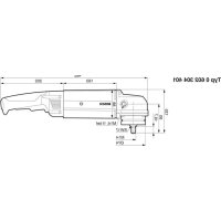

- HWS
- BOSCH
- ASSEMBLY
- GENERAL POWER TOOL SAFETY WARNINGS
- WORK AREA SAFETY
- ELECTRICAL SAFETY
- PERSONAL SAFETY
- POWER TOOL USE AND CARE
- SERVICE
- SAFETY WARNINGS FOR ANGLE GRINDER
- APPLIES FOR THE FOLLOWING TYPES
- APPLIES FOR ALL TYPES
- KICKBACK AND RELATED WARNINGS
- SAFETY WARNINGS SPECIFIC FOR GRINDING AND ABRASIVE CUTTING-OFF OPERATIONS
- SAFETY WARNINGS SPECIFIC FOR POLISHING OPERATIONS
- SAFETY WARNINGS SPECIFIC FOR WIRE BRUSHING OPERATIONS
- ADDITIONAL SAFETY WARNINGS
- WEAR SAFETY GOGGLES
- PRODUCT DESCRIPTION AND SPECIFICATIONS
- INTENDED USE
- SAFETY WARNINGS FOR THE POWER SUPPLY OF HIGH-FREQUENCY TOOLS
- NOTES ON THE POWER SUPPLY
- NOISE/VIBRATION INFORMATION
- MOUNTING THE PROTECTIVE DEVICES
- GENERAL INFORMATION
- PROTECTION GUARD FOR GRINDING (SEE FIGURE A)
- PROTECTION GUARD FOR CUTTING
- VIBRATION-DAMPENING
- AUXILIARY HANDLE
- (SEE FIGURE B)
- HAND GUARD (SEE FIGURE C)
- MOUNTING THE GRINDING TOOLS
- MOUNTING GRINDING OR CUTTING DISCS (SEE FIGURES D1-D2)
- INSTALLATION
- ENGLISH
- REMOVAL
- MACHINES WITH SPINDLE LOCK BUTTON
- APPLIES TO THE FOLLOWING TYPES
- MOUNTING THE RUBBER SANDING PLATE (SEE FIGURE F)
- MOUNTING THE BUFFING DISC (SEE FIGURE G)
- MOUNTING WIRE BRUSHES (SEE FIGURE H)
- DUST/CHIP EXTRACTION
- CONNECTION TO THE POWER SUPPLY
- MOUNTING THE CEE PLUG (SEE FIGURES 11-12)
- CHECKING THE ROTATION DIRECTION
- OPERATION
- STARTING OPERATION
- SWITCHING THE FREQUENCY CONVERTER ON/OFF
- SWITCHING THE POWER TOOL ON/OFF WITH THE ON/OFF SWITCH (SEE FIGURE J1)
- SWITCHING THE POWER TOOL ON/OFF
- WITH SAFETY SWITCH (SEE FIGURE J2)
- WORKING ADVICE
- SANDING WITH THE FLAP DISC
- CUTTING METAL (SEE FIGURE K)
- CUTTING STONE
- INFORMATION ON STRUCTURES
- ROUGH GRINDING
- SANDING WITH SANDING DISCS AND THE RUBBER SANDING PLATE
- GAUTENG - BSC SERVICE CENTRE
- KZN - BSC SERVICE CENTRE
- WESTERN CAPE - BSC SERVICE CENTRE
- BOSCH HEADQUARTERS
- DISPOSAL
- FRENCH
- SPANISH
- DUTCH
- SWEDISH
- MONTAGE
- VIBRATION-DAMPING AUXILIARY HANDLE (SEE FIGURE B)
- WASTE DISPOSAL
- FINNISH
- SUOMI
- DESCRIPTION OF THE PRODUCT AND ITS POWER
- USING THE PRODUCT
- INSTRUCTIONS FOR USE
- IT IS INTENDED FOR THE FOLLOWING TYPES
- SIGMA
- DECLARATION OF CONFORMITY
- REVISED
- THE PRODUCT IS SUITABLE FOR THE FOLLOWING TYPES
- GREEK
- LAY THE TOOL ON A FLAT SURFACE
- BUTTON
- CONNECTION OF THE POWER SUPPLY (SEE FIGURE)
- SWITCHING ON/OFF OF THE TRANSFORMER
- SEE THE ENCLOSED OPERATING INSTRUCTIONS FOR THE ELECTRICAL CONNECTION
- IT IS SUITABLE FOR THE FOLLOWING TYPES
- SEE THE ELECTRICAL CONNECTION FOR THE SOCKET OPERATION
- INFORMATION ON THE POWER SUPPLY
- POLISH
- CZECH
- GRINDING WITH SANDING PAPER ON A SANDING PLATE
- SLOVAK
- INFORMATION ON POWER SUPPLY
- ASSEMBLY OF PROTECTIVE COMPONENTS
- HUNGARIAN
- ACCESSORIES
- SERVICE CENTER AND ADVICE ON USE
- RUSSIAN
- SERVICE LIFE
- CRITERIA FOR LIMIT STATES
- TYPE AND FREQUENCY OF TECHNICAL MAINTENANCE
- STORAGE
- TRANSPORTATION
- LIST OF CRITICAL FAILURES AFFECTING THE SAFETY OF THE USER
- PERIODICITY OF TECHNICAL MAINTENANCE
- SAFETY INSTRUCTIONS
- GENERAL SAFETY INSTRUCTIONS FOR POWER TOOLS
- WARNING
- READ ALL SAFETY INSTRUCTIONS AND
- INSTRUCTIONS FOR USE. FAILURE TO FOLLOW THE SAFETY INSTRUCTIONS AND INSTRUCTIONS FOR USE MAY RESULT IN ELECTRIC SHOCK, FIRE, AND SERIOUS INJURIES
- WORKPLACE SAFETY
- YKA3AHHNOTEXHKE6E3ONACHOCTHDN YIIOBBIX WNHΦMAHH
- REFER TO THE CORRESPONDING SAFETY INSTRUCTIONS
- SPECIAL SAFETY INSTRUCTIONS FOR GRINDING AND CUTTING-OFF OPERATIONS
- ADDITIONAL SPECIAL SAFETY INSTRUCTIONS FOR CUTTING-OFF WITH ABRASIVE WHEELS
- SPECIAL SAFETY INSTRUCTIONS FOR SANDING
- SPECIAL SAFETY INSTRUCTIONS FOR WIRE BRUSHING
- SPECIAL SAFETY INSTRUCTIONS FOR CUTTING WITH ABRASIVE WHEELS
- ADDITIONAL SAFETY INSTRUCTIONS
- SAFETY INSTRUCTIONS FOR HIGH-FREQUENCY POWER TOOLS
- PRODUCT AND SERVICE DESCRIPTION
- DEHCTBHTEJIBHOAINBCEXTHIOB
- H3O6PAXEHHBIE COCTABHBIE QACTN
- INSTALLING PROTECTIVE DEVICES
- GENERAL SAFETY INSTRUCTIONS
- PROTECTIVE GUARD FOR GRINDING (SEE FIGURE A) EFFECTIVE IMMEDIATELY AFTER ASSEMBLY
- PROTECTIVE COVER
- ADJUSTING THE AUXILIARY HANDLE
- ACTION FOLLOWING THE LISTED PART NUMBERS
- MOUNTING OF WIRE BRUSHES (SEE FIGURE H)
- SUITABLE FOR THE FOLLOWING TYPES
- POWER SUPPLY CONNECTION
- FOLLOW THE SPECIFIED SAFETY INSTRUCTIONS
- STRICTLY FOLLOW THE INSTRUCTIONS IN THE OPERATING MANUAL OF THE MOTOR PROTECTION SWITCH
- INSTALLATION OF THE CEE PLUG (SEE FIG. 11-12)
- WORKING WITH THE DEVICE
- SWITCHING ON THE DEVICE
- SHARPENING WITH A GRINDING DISC
- CUTTING METAL (SEE FIG. K)
- STATIC SPECIFICATIONS
- REVERSE GRINDING
- HNHBHAHE HXJDAUHOI KYPKOHA PE3HOBO ONOPHOHNNHBHAPENKE
- COATING WITH FABRIC-COATED GRINDING DISC
- MAINTENANCE AND SERVICE
- MAINTENANCE AND CLEANING
- SERVICE AND CONSULTATION ON PRODUCT USE
- WWW.BOSCH-PT.COM
- FOR RUSSIA, BELARUS, KAZAKHSTAN, UKRAINE
- RUSSIA
- BELARUS
- KAZAKHSTAN
- ATTENTION
- UKRAINIAN
- SAFETY
- ПРАВИЛЬНЕ ОБСЛУГОВУВАННЯ ЕЛЕКТРИЧНОГО ПРИЛАДУ
- СЕРВІС
- ВКАЗІВКИ З ТЕХНІКИ БЕЗПЕКИ ДЛЯ КУТОВИХ ШЛІФУВАЛЬНИХ МАШИН
- УКРАЇНСЬКА
- СИГНАЛИ ТА ВІДПОВІДНІ ПОПЕРЕДЖЕННЯ
- ALWAYS WEAR PROTECTIVE GOGGLES WHEN CUTTING WITH GRINDING WHEELS
- OPERATING INSTRUCTIONS
- INFORMATION ON VIBRATION
- MOUNTING
- MOUNTING PROTECTIVE DEVICES
- IMPORTANT INSTRUCTIONS
- PROTECTIVE GUARD FOR GRINDING
- THE FOLLOWING TYPES ARE AVAILABLE
- PROTECTIVE GUARD FOR CUTTING
- PO3NOBCIOXKYCTBCHAHACTYNHITNN
- AUXILIARY HANDLE (SEE FIGURE B)
- MOUNTING THE RUBBER BACKING PAD (SEE FIGURE F)
- DEMOUNTING
- MOUNTING OF THE THRUST WASHER (SEE FIG. 7)
- RECOMMENDED FOR USE WITH A RESIDUAL CURRENT DEVICE
- MOUNTING THE PLUG (SEE FIGURES 11-12)
- AFTER THIS, CHECK THE DIRECTION OF ROTATION
- CHECKING THE DIRECTION OF ROTATION
- STARTING THE MACHINE
- SWITCHING ON/OFF THE FREQUENCY CONVERTER
- SWITCHING ON/OFF THE ELECTRICAL SUPPLY
- BMNKAHHBMKNKAHHENEKTPONPHNADY
- KASAIKA
- KB3MET
- BPYBIBIK TERICTEY MAUNHNAPBH NAADANANY KEIHERIKAYINCI3DKTEXNKACBL
- TOMEHDERIYTPNPYWNTNICTI
- THE CONTROL PANEL, LIFTING MECHANISM, AND SAFETY DEVICES ARE EQUIPPED WITH THE FOLLOWING COMPONENTS
- BEFORE FIRST USE, CHECK THE DEVICE FOR DAMAGE
- CAIKECIK MONIMDEMECI
- C
- XNHAY
- KOPRANBIW KAA6DBKTAPBH OPHATY
- KANNBL HCYCKAYNBIKRAP
- NEKTP KYPAANDAPBI UHHNDNBI 6YFARAY NEPHECIMEN
- TOMEHDERIYTPNPYWNTHICTI
- PLEASE READ THE TEXT BEFORE INSTALLATION (INSTRUCTIONS)
- KAZAKH
- OUTPUT
- SPARE PARTS AND ACCESSORIES
- ENERGY EFFICIENCY
- SEE THE CONNECTION DIAGRAM (SEE FIGURES I1-I2)
- DO NOT OPERATE THE CRANE WITHOUT PROPER GROUNDING
- PAIANDAANHY
- FOR CUTTING WITH A CUTTING WHEEL
- CUTTING WITH THE CUTTING WHEEL – SAFETY INSTRUCTIONS (SEE FIGURE 1)
- THE FOLLOWING INSTRUCTIONS ARE IMPORTANT
- ELECTRIC ROTARY SWITCH (SEE FIGURE 2)
- CONNECTION TERMINALS AND CONNECTION
- METAL HOUSING (SEE FIGURE 3)
- ROMANA
- BULGARIAN
- SPECIAL SAFETY INSTRUCTIONS FOR GRINDING AND CUTTING WITH ABRASIVE DISCS
- SPECIAL SAFETY INSTRUCTIONS FOR GRINDING DISCS
- SPECIAL SAFETY INSTRUCTIONS FOR WORKING WITH CIRCULAR SAWS
- SPECIAL INSTRUCTIONS FOR SAFE WORK WITH THE TOOL
- SPECIAL INSTRUCTIONS FOR SAFE WORK WHEN CUTTING WALLS AND FABRICS
- ADDITIONAL INSTRUCTIONS FOR SAFE WORK
- INSTRUCTIONS FOR SAFE HANDLING OF HIGH-VOLTAGE ELECTRIC TOOLS
- DISPLAY (SEE FIG. C)
- MOUNTING THE CUTTING TOOLS
- MOUNTING THE CUTTING DISC FOR CUTTING, ROUGHING OR FINE CUTTING (SEE FIGURES D1 - D2)
- POWER TOOL WITH SPINDLE LOCK BUTTON
- MOUNTING THE CUTTING GUARD (SEE FIGURE F)
- THEN CHECK THE DIRECTION OF ROTATION
- WORKING WITH THE POWER TOOL
- SWITCHING ON
- SWITCHING THE POWER TOOL ON AND OFF
- SWITCHING ON AND OFF WITH THE TRIGGER SWITCH (SEE FIGURE 1)
- FOR THE FOLLOWING MODELS
- SWITCHING ON AND OFF WITH THE LOCK BUTTON (SEE FIGURE 2)
- OPERATION WITH DUST EXTRACTION
- METAL CUTTING (SEE FIGURE)
- CUTTING STONE MATERIALS
- INSTRUCTIONS FOR STATIC LOAD
- PIPE CUTTING
- CUTTING WITH A DISC WITH A SOFT BOND
- SUPPORT WITH A SUPPORT DISC
- SAFETY WARNINGS FOR ANGLE GRINDERS
- SAFETY WARNINGS FOR GRINDING AND CUTTING-OFF OPERATIONS
- SAFETY WARNINGS FOR GRINDING AND CUTTING-OFF OPERATIONS WITH WIRE BRUSHES
- ONTH6E36DNOCHN HANOEMN 3A 6PYCEHE,6PYCEHE CO 6PYCHAXAPTNA,PA0TEHE CO KXHAUHHYETK,NONPAHE EN CEPEHE CO 6PYCNH NOOH BAXK 3A CHTNEONB
- MAKEDOHCKN
- SHORT CIRCUIT AND PROPER SAFETY INSTRUCTIONS
- SPECIAL SAFETY WARNINGS FOR BRUSHING AND POLISHING OPERATIONS
- SAFETY INSTRUCTIONS FOR THE BRUSH CUTTER
- SPECIAL SAFETY INSTRUCTIONS FOR CUTTING WITH A SAW BLADE
- SPECIAL SAFETY INSTRUCTIONS FOR WORKING WITH WIRE BRUSHES
- MACEDONIAN
- SAFETY INSTRUCTIONS FOR POWER SUPPLY WITH HIGH-FREQUENCY DEVICES
- DESCRIPTION OF THE PRODUCT AND PERFORMANCE
- IMPORTANT FOR THE FOLLOWING TYPES
- BAXN 3A CHTTNOBN
- NMYCTPAUNJA HA KOMNOHEHTN
- INFORMATION ON SUPPLY WITH ENERGY
- MOUNTING THE PROTECTIVE DEVICES, SUCTION, AND EXTRACTION (SEE FIGURES D1-D2)
- ELECTRICAL DEVICE WITH KEY FOR LOCKING THE SPINDLE
- MOUNTING THE BEAM ON THE FENCE FOR THE BEAM
- (SEE FIGURE F)
- ROOTS
- ADJUSTMENT
- MOUNTING THE BEAM FOR THE FENCE (SEE FIGURE G)
- MOUNTING THE CHAIN KIT (SEE FIGURE H)
- USE
- CONNECTION TO POWER SUPPLY
- FOR YOUR SAFETY, READ THE SAFETY INSTRUCTIONS AND THE INSTALLATION MANUAL BEFORE INSTALLING THE RCD
- CONNECTING THE POWER CORD (SEE FIGURES 11-12)
- FINALLY, CHECK THE CORRECT TIME
- CHECKING THE CORRECT TIME
- PUTTING INTO USE
- SWITCHING ON/OFF THE DEVICE
- SWITCHING ON/OFF THE ELECTRICAL DEVICE WITH THE ON/OFF SWITCH (SEE FIGURE J1)
- IMPORTANT FOR THE FOLLOWING STEPS
- SWITCHING ON/OFF THE ELECTRICAL DEVICE WITH THE ON/OFF SWITCH (SEE FIGURE J2)
- ADVICE FOR OPERATION
- AFTER-SALES SERVICE AND ADVICE ON USE
- MACEDONIA
- ONLY FOR EU COUNTRIES
- SERBIAN
- POWER TOOLS WITH SPINDLE LOCK BUTTON
- THE FOLLOWING TYPES APPLY
- MOUNTING THE RUBBER SANDING PAD (SEE FIGURE F)
- INSERTION
- INSTALLATION (SEE FIGURE G)
- WARNINGS FOR POWER SUPPLY
- GENERAL INSTRUCTIONS
- WITH A SAFETY SLIDE SWITCH (SEE FIGURE J1)
- CROATIAN
- NOTES ON ELECTRICAL POWER SUPPLY
- INFORMATION ON NOISE AND VIBRATION
- ESTONIAN
- STATIC GUIDELINES
- GRINDING
- LATVIAN
- ADDITIONAL SPECIFIC SAFETY INSTRUCTIONS FOR CUTTING
- INSTRUCTIONS FOR ELECTRICAL CONNECTION
- ATTACHING THE PROTECTIVE DEVICES
- GRINDING GUARD (FIGURE A)
- FOR TOOLS
- CUTTING GUARD
- AUXILIARY HANDLE WITH VIBRATION DAMPING (FIGURE B)
- HAND GUARD (FIGURE C)
- MOUNTING THE SANDING TOOLS GENERAL INSTRUCTIONS
- MOUNTING SANDING, CUTTING, AND ROUGH SANDING DISCS (FIGURES D1 - D2)
- MOUNTING THE RUBBER SANDING PAD (FIGURE F)
- MOUNTING THE POLISHING FLEECE DISC (FIGURE G)
- MOUNTING THE WIRE BRUSH (FIGURE H)
- TOOLS
- DUST AND CHIP EXTRACTION
- POWER TOOL WITH SPINDLE LOCKING KEY
- APPLICABLE TO THE FOLLOWING TYPES
- LITHUANIAN
- WITH SAFETY LOCK (SEE FIGURE J2)
- ONLY FOR THE FOLLOWING TYPES
- SUPPIMER
Brand : BOSCH
Model : HWS 88230 Professional
Category : Angle grinder