HWS 77175 Professional - Angle grinder BOSCH - Free user manual and instructions
Find the device manual for free HWS 77175 Professional BOSCH in PDF.

| Product type | High-frequency angle grinder |
| Brand | Bosch |
| Model | HWS 77175 Professional |
| Rated voltage | 265 V |
| Frequency | 200 Hz |
| Rated input power | 1200 W |
| Rated output power | 1000 W |
| No-load speed | 8480 rpm |
| Max. grinding wheel diameter | 125 mm |
| Spindle thread | M14 |
| Weight (with auxiliary handle) | 3.2 kg |
| Protection class | II (double insulation) |
| Protection type | IP 20 |
| Intended use | Cutting, rough grinding, brushing of metal and stone (without water), sanding and polishing depending on model |
| Main functions | Grinding, cutting, deburring, brushing, sanding, polishing |
| Safety | Kickback protection, adjustable protective guard, anti-vibration auxiliary handle, spindle lock, safety switch |
| Maintenance and cleaning | Clean ventilation slots with compressed air, check direction of rotation, use original cables, lubricate gear every 300 hours |
| Spare parts and repairability | Accessories available from Bosch, repairs by authorized service center |
| Power supply | Frequency converter required, special cable 4 m without plug, 4-pole CEE plug |
| General information | Professional grinder for heavy-duty use, compliant with EN 60745, CE |
Frequently Asked Questions - HWS 77175 Professional BOSCH
User questions about HWS 77175 Professional BOSCH
0 question about this device. Answer the ones you know or ask your own.
Ask a new question about this device
Download the instructions for your Angle grinder in PDF format for free! Find your manual HWS 77175 Professional - BOSCH and take your electronic device back in hand. On this page are published all the documents necessary for the use of your device. HWS 77175 Professional by BOSCH.
USER MANUAL HWS 77175 Professional BOSCH
OBJ_BUCH-2187-002.book Page 1 Wednesday, November 2, 2016 1:43 PM
natural_image
Two Bosch electric motors shown from different angles (no text or symbols visible)Robert Bosch Power Tools GmbH
70538 Stuttgart
GERMANY
www.bosch-pt.com
1609 92A 36G (2015.07) AS / 473 EURO

1609 92A 36G
HWS
0 602 301 4.. | 0 602 304 40. | 0 602 305 40. | 0 602 306 434 | 0 602 324 4.. | 0 602 329 5.. | 0 602 331 5.. | 0 602 332 5.. | 0 602 334 5..

BOSCH
tr Original isolme tafimal
OBJ_BUCH-2487-002.book Page 2 Wednesday, November 2, 2016 4:43 PM
21
Deutsch.... Seite 7
English Page 22
Français Page 36
OBJ_BUCH-2487-002.book Page 3 Wednesday, November 2, 2016 4:43 PM


3|


1 609 92A 36G | (2.11.16) Bosch Power Tools


OBJ_BUCH-2487-002.book Page 4 Wednesday, November 2, 2016 4:43 PM


4
1 609 92A 36G | (2.11.16) Bosch Power Tools


5


OBJ_BUCH-2487-002.book Page 6 Wednesday, November 2, 2016 4:43 PM


6
natural_image
Illustration of a robotic arm performing a circular motion on a platform, with no visible text or symbols1 609 92A 36G | (2.11.16) Bosch Power Tools


Deutsch|7
Deutsch
Sicherheitshinweise
Henk Becker Executive Vice President Engineering Helmut Heinzelmann Head of Product Certification PT/ECS
julse Sea i.v. h.w.
Robert Bosch Power Tools GmbH
70538 Stuttgart, GERMANY
Stuttgart, 01.01.2017
Montage
General Power Tool Safety Warnings
WARNING Read all safety warnings and all instructions. Failure to follow the warnings and instructions may result in electric shock, fire and/or serious injury.
Save all warnings and instructions for future reference. The term "power tool" in the warnings refers to your mains-operated (corded) power tool or battery-operated (cordless power tool.
Work area safety
- Keep work area clean and well lit. Cluttered or dark areas invite accidents.
Do not operate power tools in explosive atmospheres, such as in the presence of flammable liquids, gases or dust. Power tools create sparks which may ignite the dust or fumes. - Keep children and bystanders away while operating a power tool. Distractions can cause you to lose control.
Electrical safety
▶ Power tool plugs must match the outlet. Never modify the plug in any way. Do not use any adapter plugs with earthed (grounded) power tools. Unmodified plugs and matching outlets will reduce risk of electric shock.
- Avoid body contact with earthed or grounded surfaces, such as pipes, radiators, ranges and refrigerators. There is an increased risk of electric shock if your body is earthed or grounded.
▶ Do not expose power tools to rain or wet conditions.
Water entering a power tool will increase the risk of electric shock.
▶ Do not abuse the cord. Never use the cord for carrying, pulling or unplugging the power tool. Keep cord away from heat, oil, sharp edges and moving parts. Damaged or entangled cords increase the risk of electric shock.
- When operating a power tool outdoors, use an extension cord suitable for outdoor use. Use of a cord suitable for outdoor use reduces the risk of electric shock.
▶ If operating a power tool in a damp location is unavoidable, use a residual current device (RCD) protected supply. Use of an RCD reduces the risk of electric shock.
Personal safety
Stay alert, watch what you are doing and use common sense when operating a power tool. Do not use a power tool while you are tired or under the influence of drugs, alcohol or medication. A moment of inattention while operating power tools may result in serious personal injury.
▶ Use personal protective equipment. Always wear eye protection. Protective equipment such as dust mask, non-skid safety shoes, hard hat, or hearing protection used for appropriate conditions will reduce personal injuries.
▶ Prevent unintentional starting. Ensure the switch is in the off-position before connecting to power source and/or battery pack, picking up or carrying the tool. Carrying power tools with your finger on the switch or energising power tools that have the switch on invites accidents.
Remove any adjusting key or wrench before turning the power tool on. A wrench or a key left attached to a rotating part of the power tool may result in personal injury.
▶ Do not overreach. Keep proper footing and balance at all times. This enables better control of the power tool in unexpected situations.
▶ Dress properly. Do not wear loose clothing or jewellery. Keep your hair, clothing and gloves away from moving parts. Loose clothes, jewellery or long hair can be caught in moving parts.
If devices are provided for the connection of dust extraction and collection facilities, ensure these are connected and properly used. Use of dust collection can reduce dust-related hazards.
Power tool use and care
▶ Do not force the power tool. Use the correct power tool for your application. The correct power tool will do the job better and safer at the rate for which it was designed.
▶ Do not use the power tool if the switch does not turn it on and off. Any power tool that cannot be controlled with the switch is dangerous and must be repaired.
▶ Disconnect the plug from the power source and/or the battery pack from the power tool before making any adjustments, changing accessories, or storing power tools. Such preventive safety measures reduce the risk of starting the power tool accidentally.
▶ Store idle power tools out of the reach of children and do not allow persons unfamiliar with the power tool or these instructions to operate the power tool. Power tools are dangerous in the hands of untrained users.
- Maintain power tools. Check for misalignment or binding of moving parts, breakage of parts and any other condition that may affect the power tool's operation. If damaged, have the power tool repaired before use. Many accidents are caused by poorly maintained power tools.


English | 23
- Keep cutting tools sharp and clean. Properly maintained cutting tools with sharp cutting edges are less likely to bind and are easier to control.
▶ Use the power tool, accessories and tool bits etc. in accordance with these instructions, taking into account the working conditions and the work to be performed. Use of the power tool for operations different from those intended could result in a hazardous situation.
Service
▶ Have your power tool serviced by a qualified repair person using only identical replacement parts. This will ensure that the safety of the power tool is maintained.
Safety Warnings for Angle Grinder
Safety warnings common for sanding with sanding discs and polishing
Applies for the following types:
-06023014..
-060230540.
-0602306434
-060232440.
-06023014.. -060230540. -0602306434 -060232440.
This power tool is to be used as a sander and polisher. Observe all safety warnings, instructions, illustrations and data supplied with the power tool. Non-observance of the following instructions can lead to electric shock, fire and/or serious injury.
▶ Operations such as grinding, wire brushing or cutting-off are not recommended to be performed with this power tool. Operations for which the power tool was not designed may create a hazard and cause personal injury.
Safety warnings common for grinding, working with wire brushes and cut-off grinding
Applies for the following types:
-060230440.
- 060232444,...464,...474,...434
-06023295..
-06023315..
-06023325..
-06023345..
- 0 602 304 40. - 0 602 324 44., ... 464, ... 474, ... 434 - 0 602 329 5.. - 0 602 331 5.. - 0 602 332 5.. - 0 602 334 5..
This power tool is to be used as a grinder, wire brush and cut off grinder. Observe all safety warnings, instructions, illustrations and data supplied with the power tool. Non-observance of the following instructions can lead to electric shock, fire and/or serious injury.
▶ Operations such as sanding or polishing are not recommended to be performed with this power tool. Operations for which the power tool was not designed may create a hazard and cause personal injury.
Safety warnings that are common for grinding, sanding, wire brushing, polishing and abrasive cutting off operations
Applies for all types
Do not use accessories which are not specifically designed and recommended by the tool manufacturer. Just because the accessory can be attached to your power tool, it does not assure safe operation.
The rated speed of the accessory must be at least equal to the maximum speed marked on the power tool. Accessories running faster than their rated speed can break and fly apart.
The outside diameter and the thickness of your accessory must be within the capacity rating of your power tool. Incorrectly sized accessories cannot be adequately guarded or controlled.
Threaded mounting of accessories must match the grinder spindle thread. For accessories mounted by flanges, the arbour hole of the accessory must fit the locating diameter of the flange. Accessories that do not match the mounting hardware of the power tool will run out of balance, vibrate excessively and may cause loss of control.
Do not use a damaged accessory. Before each use inspect the accessory such as abrasive wheels for chips and cracks, backing pad for cracks, tear or excess wear, wire brush for loose or cracked wires. If power tool or accessory is dropped, inspect for damage or install an undamaged accessory. After inspecting and installing an accessory, position yourself and bystanders away from the plane of the rotating accessory and run the power tool at maximum no-load speed for one minute. Damaged accessories will normally break apart during this test time.
▶ Wear personal protective equipment. Depending on application, use face shield, safety goggles or safety glasses. As appropriate, wear dust mask, hearing protectors, gloves and shop apron capable of stopping small abrasive or workpiece fragments. The eye protection must be capable of stopping flying debris generated by various operations. The dust mask or respirator must be capable of filtrating particles generated by your operation. Prolonged exposure to high intensity noise may cause hearing loss.
▶ Keep bystanders a safe distance away from work area. Anyone entering the work area must wear personal protective equipment. Fragments of workpiece or of a broken accessory may fly away and cause injury beyond immediate area of operation.
Hold the power tool by insulated gripping surfaces only, when performing an operation where the cutting accessory may contact hidden wiring or its own cord. Cutting accessory contacting a "live" wire may make exposed metal parts of the power tool "live" and could give the operator an electric shock.
▶ Position the cord clear of the spinning accessory. If you lose control, the cord may be cut or snagged and your hand or arm may be pulled into the spinning wheel.
▶ Never lay the power tool down until the accessory has come to a complete stop. The spinning wheel may grab the surface and pull the power tool out of your control.
▶ Do not run the power tool while carrying it at your side. Accidental contact with the spinning accessory could snag your clothing, pulling the accessory into your body.
24| English
▶ Regularly clean the power tool's air vents. The motor's fan will draw the dust inside the housing and excessive accumulation of powdered metal may cause electrical hazards.
▶ Do not operate the power tool near flammable materials. Sparks could ignite these materials.
▶ Do not use accessories that require liquid coolants. Using water or other liquid coolants may result in electrocution or shock.
Kickback and related warnings
▶ Kickback is a sudden reaction to a pinched or snagged rotating wheel, backing pad, brush or any other accessory. Pinching or snagging causes rapid stalling of the rotating accessory which in turn causes the uncontrolled power tool to be forced in the direction opposite of the accessory's rotation at the point of the binding.
For example, if an abrasive wheel is snagged or pinched by the workpiece, the edge of the wheel that is entering into the pinch point can dig into the surface of the material causing the wheel to climb out or kick out. The wheel may either jump toward or away from the operator, depending on direction of the wheel's movement at the point of pinching. Abrasive wheels may also break under these conditions.
Kickback is the result of power tool misuse and/or incorrect operating procedures or conditions and can be avoided by taking proper precautions as given below.
- Maintain a firm grip on the power tool and position your body and arm to allow you to resist kickback forces. Always use auxiliary handle, if provided, for maximum control over kickback or torque reaction during start-up. The operator can control torque reactions or kickback forces, if proper precautions are taken.
▶ Never place your hand near the rotating accessory. Accessory may kickback over your hand.
Do not position your body in the area where power tool will move if kickback occurs. Kickback will propel the tool in direction opposite to the wheel's movement at the point of snagging.
▶ Use special care when working corners, sharp edges, etc. Avoid bouncing and snagging the accessory. Corners, sharp edges or bouncing have a tendency to snag the rotating accessory and cause loss of control or kickback.
▶ Do not attach a saw chain woodcarving blade or toothed saw blade. Such blades create frequent kickback and loss of control.
Safety warnings specific for Grinding and Abrasive Cutting-Off operations
▶ Use only wheel types that are recommended for your power tool and the specific guard designed for the selected wheel. Wheels for which the power tool was not designed cannot be adequately guarded and are unsafe.
The grinding surface of the centre depressed wheels must be mounted below the plane of the guard lip. An improperly mounted wheel that projects through the plane of the guard lip cannot be adequately protected.
The guard must be securely attached to the power tool and positioned for maximum safety, so the least amount of wheel is exposed towards the operator. The guard helps to protect operator from broken wheel fragments, accidental contact with wheel and sparks that could ignite clothing.
▶ Wheels must be used only for recommended applications. For example: do not grind with the side of the cut-off wheel. Abrasive cut-off wheels are intended for peripheral grinding; side forces applied to these wheels may cause them to shatter.
▶ Always use undamaged wheel flanges that are of correct size and shape for your selected wheel. Proper wheel flanges support the wheel thus reducing the possibility of wheel breakage. Flanges for cut-off wheels may be different from grinding wheel flanges.
▶ Do not use worn down reinforced wheels from larger power tools. Wheels intended for larger power tools are not suitable for the higher speed of a smaller tool and may burst.
Additional safety warnings specific for abrasive cutting off operations
▶ Do not "jam" the cut-off wheel or apply excessive pressure. Do not attempt to make an excessive depth of cut. Overstressing the wheel increases the loading and susceptibility to twisting or binding of the wheel in the cut and the possibility of kickback or wheel breakage.
Do not position your body in line with and behind the rotating wheel. When the wheel, at the point of operation, is moving away from your body, the possible kickback may propel the spinning wheel and the power tool directly at you.
When wheel is binding or when interrupting a cut for any reason, switch off the power tool and hold the power tool motionless until the wheel comes to a complete stop. Never attempt to remove the cut-off wheel from the cut while the wheel is in motion otherwise kickback may occur. Investigate and take corrective action to eliminate the cause of wheel binding.
▶ Do not restart the cutting operation in the workpiece. Let the wheel reach full speed and carefully re-enter the cut. The wheel may bind, walk up or kickback if the power tool is restarted in the workpiece.
▶ Support panels or any oversized workpiece to minimize the risk of wheel pinching and kickback. Large workpieces tend to sag under their own weight. Supports must be placed under the workpiece near the line of cut and near the edge of the workpiece on both sides of the wheel.
▶ Use extra caution when making a "pocket cut" into existing walls or other blind areas. The protruding wheel may cut gas or water pipes, electrical wiring or objects that can cause kickback.
Safety warnings specific for sanding operations
▶ Do not use excessively oversized sanding disc paper. Follow manufacturers recommendations, when selecting sanding paper. Larger sanding paper extending be


English | 25
yond the sanding pad presents a laceration hazard and may cause snagging, tearing of the disc, or kickback.
Safety warnings specific for polishing operations
Do not allow any loose portion of the polishing bonnet or its attachment strings to spin freely. Tuck away or trim any loose attachment strings. Loose and spinning attachment strings can entangle your fingers or snag on the workpiece.
Safety warnings specific for wire brushing operations
▶ Be aware that wire bristles are thrown by the brush even during ordinary operation. Do not overstress the wires by applying excessive load to the brush. The wire bristles can easily penetrate light clothing and/or skin.
▶ If the use of a guard is recommended for wire brushing, do not allow any interference of the wire wheel or brush with the guard. Wire wheel or brush may expand in diameter due to work load and centrifugal forces.
Additional safety warnings
Wear safety goggles.

▶ Use suitable detectors to determine if utility lines are hidden in the work area or call the local utility company for assistance. Contact with electric lines can lead to fire and electric shock. Damaging a gas line can lead to explosion. Penetrating a water line causes property damage or may cause an electric shock.
▶ Release the On/Off switch and set it to the off position when the power supply is interrupted, e.g., in case of a power failure or when the mains plug is pulled. This prevents uncontrolled restarting.
▶ Do not touch grinding and cutting discs before they have cooled down. The discs can become very hot while working.
When working with the machine, always hold it firmly with both hands and provide for a secure stance. The power tool is guided more secure with both hands.
▶ Secure the workpiece. A workpiece clamped with clamping devices or in a vice is held more secure than by hand.
Connect the machine to a mains supply with proper earthing connection. Socket outlet and extension cable must be equipped with an operative protective conductor.
Products sold in AUS and NZ only: Use a residual current device (RCD) with a rated residual current of 30 mA or less.
Safety Warnings for the Power Supply of High-frequency Tools
The safety warnings and working instructions of the frequency converter are to be strictly observed! For detailed information, contact the manufacturer of the frequency converter.
The frequency converter must be secured with a residual current protection device when working in an envi-
Bosch Power Tools 1 609 92A 36G | (2.11.16)
ronment where special protection for persons is necessary. The special protection of persons is required, for example, when working in damp rooms or with materials that can produce current-conducting dust. Not using a residual current protection device can lead to electrical shock, risk of fire, or serious injuries.
The residual current protection device should be installed in the power supply network only by a qualified electrician. Only in this manner can proper functioning be ensured.
The output voltage and frequency of the frequency converter must correspond with the data on the type plate of the high-frequency tool.
▶ Operate the power tool exclusively with a fitting plug. The CEE plug must be dimensioned for the nominal current that the power tool requires (see "Technical Data").
▶ Plug mounting and connection to the power supply is to be carried out by a qualified electrician trained in handling high-frequency tool systems.
▶ Use only original cables! Before each use, check the power tool, cable and plug for possible damage. Cables and plugs may not be repaired, but must be exchanged in order to avoid danger.
Product Description and Specifications

Read all safety warnings and all instructions. Failure to follow the warnings and instructions may result in electric shock, fire and/or serious injury.
While reading the operating instructions, unfold the graphics page for the machine and leave it open.
Intended Use
Applies for the following types:
-06023014..
-060230540.
-0602306434
-060232440.
The machine is intended for sanding and polishing metal and coated surfaces without the use of water.
Applies for the following types:
-060230440
- 060232444,...464,...474,...434
-06023295..
-06023315..
-06023325..
-06023345..
The machine is intended for cutting, roughing and brushing of metal and stone materials without the use of water.
For cutting with bonded abrasives, a special cutting guide (accessory) must be used.
When cutting in stone, provide for sufficient dust extraction.
Applies for all types

26|English
Use only the blade guards and clamping nuts provided or specifically released for this power tool.
Product Features
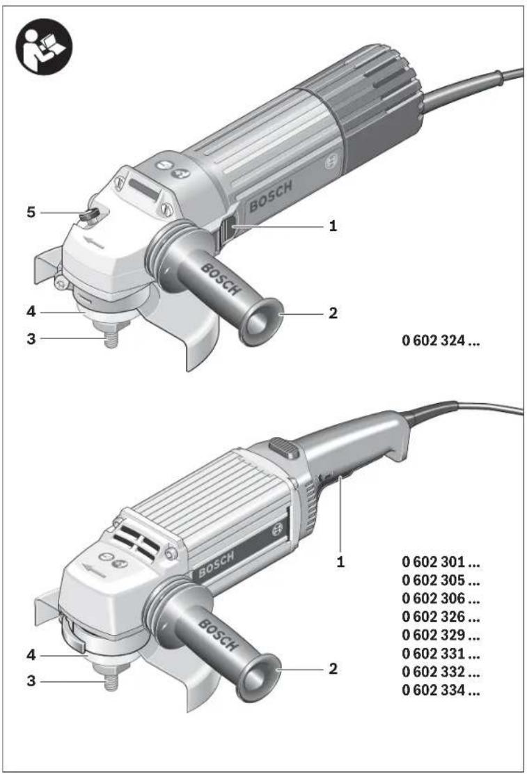
The numbering of the product features refers to the illustration of the machine on the graphics page.
1 On/Off switch
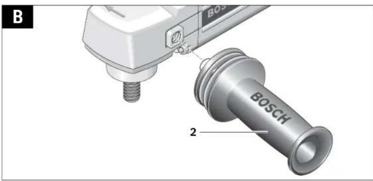
2 Auxiliary handle
3 Grinder spindle
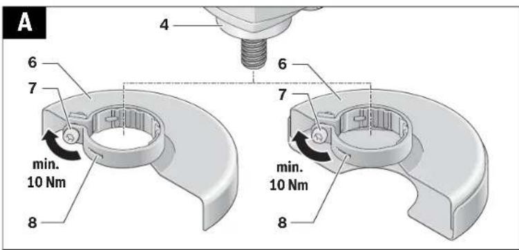
4 Spindle collar
5 Spindle lock button
6 Blade guard
7 Locking screw for protection guard
8 Encoding key
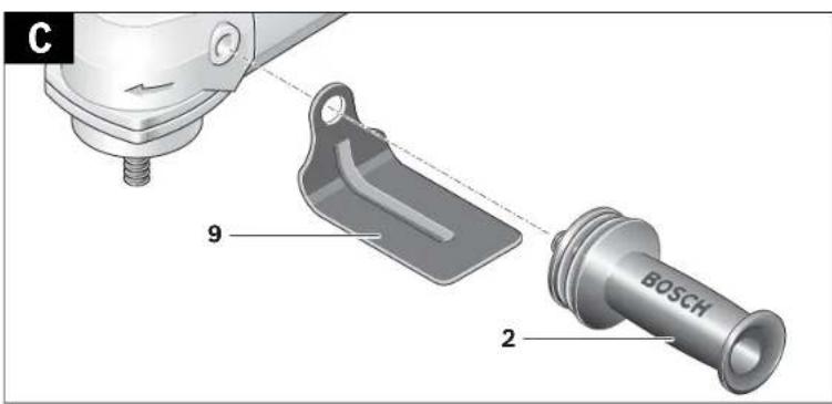
9 Hand guard*
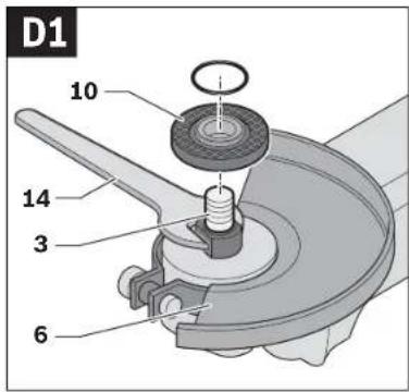
.0 Mounting flange with O-ring
.1 Grinding/cutting disc
12 Clamping nut
13 Two-pin spanner
14 Open-end spanner, size 17 mm
15 Round nut*
16 Sanding sheet*
17 Rubber sanding plate*
18 Buffing disc*
19 Wire brush
20 Cable strain relief (CEE plug)
21 Plug insert (CEE plug)
22 Screw (CEE plug)
23 Screws in plug insert 21 (CEE plug)
24 CEE plug
25 Plastic sleeve (CEE plug)
*Accessories shown or described are not part of the standard delivery scope of the product. A complete overview of accessories can be found in our accessories program.
Technical Data
| High-frequency Angle Grinder | ||||
| Article number 0 602 301 ... | ...401 | ...404 | ...434 | |
| Rated voltage | V | 2 | 6 | 5 |
| Frequency | Hz 200 200 300 | |||
| Rated power input | W | 6 | 0 | 0 |
| Rated power output | W | 4 | 4 | 0 |
| Nominal current | A | 1 | . | 6 |
| No-load speed | min^-1 | 4100 4100 6150 | ||
| Grinding disc diameter, max. | mm 125 125 125 | |||
| Thread of grinder spindle | M14 | M14 | M14 | |
| Weight according to EPTA-Procedure 01:2014– with vibration-damping auxiliary handle | kg | 3.2 | 3.2 | 3.2 |
| Protection class | ⏻/I | ⏻/I | ⏻/I | |
| Degree of protection | IP 20 | IP 20 | IP 20 | |
| High-frequency Angle Grinder | |||||
| Article number | 0 602 304 ... | 0 602 305 ... | |||
| ... 404 | ... 407 | ... 401 | ... 404 | ||
| Rated voltage | V 135 | 72 265 | 135 | ||
| Frequency | Hz | 200 200 | 200 200 | ||
| Rated power input | W | 950 950 | 950 950 | ||
| Rated power output | W | 700 700 | 700 700 | ||
| Nominal current | A | 5.5 | 10 | 2.8 | 5.5 |
| No load speed | min^-1 | 5 750 | 5 750 | 1 750 | 1 750 |
| Grinding disc diameter, max. | mm | 180 180 | 175 175 | ||
| Thread of grinder spindle | M14 | M14 | M14 | M14 | |
| Weight according to EPTA-Procedure 01:2014– with vibration-damping auxiliary handle | kg | 5.3 | 5.3 | 4.8 | 4.8 |
| Protection class | ⊕ / I | ⊕ / I | ⊕ / I | ⊕ / I | |
| Degree of protection | IP 20 | IP 20 | IP 20 | IP 20 | |
1 609 92A.36G | (2.11.16) Bosch Power Tools
135 200
600 900
440630
3.3 3.3
English | 27
High-frequency Angle Grinder
| Article number | 0 602 306 ... | 0 602 324 ... | ||||
| ... 434 | ... 401 | ... 404 | ... 407 | ... 434 | ||
| Rated voltage | V | 2 | 0 | 0 | 265 135 72 200 | |
| Frequency | Hz 300 200 200 200 300 | |||||
| Rated power input | W | 1 | 4 | 5 | 0 | 520 520 520 800 |
| Rated power output | W | 1 | 0 | 5 | 0 | 360 360 360 550 |
| Nominal current | A | 5.5 | 1.6 | 3.2 | 6.0 | 3.2 |
| No-load speed | min^-1 | 1700 | 4900 | 4900 | 4900 | 7300 |
| Grinding disc diameter, max. | mm 175 125 125 125 125 | |||||
| Thread of grinder spindle | M14 | M14 | M14 | M14 | M14 | |
| Weight according to EPTA-Procedure 01:2014– with vibration-damping auxiliary handle | kg | 4.8 | 2.3 | 2.3 | 2.3 | 2.5 |
| Protection class | ± /I | ± /I | ± /I | ± /I | ± /I | |
| Degree of protection | IP 20 | IP 20 | IP 20 | IP 20 | IP 20 | |
High-frequency Angle Grinder
| Article number | 0 602 324 ... | ||||
| ... 441 | ... 444 | ... 447 | ... 474 | ||
| Rated voltage | V | 265 | 135 | 72 | 135 |
| Frequency | Hz | 200 | 200 | 200 | 200 |
| Rated power input | W | 520 | 520 | 520 | 520 |
| Rated power output | W | 360 | 360 | 360 | 360 |
| Nominal current | A | 1.6 | 3.2 | 6.0 | 3.2 |
| No-load speed | min^-1 | 5850 | 5850 | 5850 | 6850 |
| Grinding disc diameter, max. | mm | 125 | 125 | 125 | 125 |
| Thread of grinder spindle | M14 | M14 | M14 | M14 | |
| Weight according to EPTA-Procedure 01:2014 – with vibration-damping auxiliary handle | kg | 2.5 | 2.5 | 2.5 | 2.5 |
| Protection class | ⊕ /1 | ⊕ /1 | ⊕ /1 | ⊕ /1 | |
| Degree of protection | IP 20 | IP 20 | IP 20 | IP 20 | |
High-frequency Angle Grinder
| Article number | 0 602 329 ... | ||
| ...501 | ...534 | ||
| Rated voltage | V | 265 | 2 |
| Frequency | Hz | 200 | 300 |
| Rated power input | W | 1200 | 1800 |
| Rated power output | W | 1000 | 1500 |
| Nominal current | A | 3.3 | 6.4 |
| No-load speed | min^-1 | 8480 | 8480 |
| Grinding disc diameter, max. | mm | 180 | 180 |
| Thread of grinder spindle | M14 | M14 | |
| Weight according to EPTA-Procedure 01:2014– with vibration-damping auxiliary handle | kg | 5.8 | 5.8 |
| Protection class | /1 | /1 | |
| Degree of protection | IP 20 | IP 20 | |
Bosch Power Tools 1 609 92A 36G | (2.11.16)
0
0
28| English
High-frequency Angle Grinder
| Article number | 0 602 331 ... | ||||
| ...501 | ...504 | ...507 | ...534 | ||
| Rated voltage | V 265 135 72 200 | ||||
| Frequency | Hz 200 200 200 300 | ||||
| Rated power input | W 1950 1950 1950 2900 | ||||
| Rated power output | W 1500 1500 1500 2200 | ||||
| Nominal current | A | 5 | 10 18 10 | ||
| No-load speed | min^-1 | 8480 8480 8480 8480 | |||
| Grinding disc diameter, max. | mm 180 180 180 180 | ||||
| Thread of grinder spindle | M14 M14 M14 M14 | ||||
| Weight according to EPTA-Procedure 01:2014– with vibration-damping auxiliary handle | kg 7.1 7.1 7.1 7.1 | ||||
| Protection class | ⊕ /I /I /I /I | ⊕ | ⊕ | ⊕ | |
| Degree of protection | IP 20 | IP 20 | IP 20 | IP 20 | |
High-frequency Angle Grinder
| Article number | 0 602 332 ... | |||||
| ...501 | ...504 | ...507 | ...534 | ...511 | ||
| Rated voltage | V | 265 | 135 | 72 | 200 | 72 |
| Frequency | Hz | 200 | 200 | 200 | 300 | 300 |
| Rated power input | W | 1950 | 1950 | 1950 | 2900 | 2900 |
| Rated power output | W | 1500 | 1500 | 1500 | 2200 | 2200 |
| Nominal current | A | 5 | 10 | 18 | 10 | 27 |
| No-load speed | min^-1 | 6600 | 6600 | 6600 | 6600 | 6600 |
| Grinding disc diameter, max. | mm | 230 | 230 | 230 | 230 | 230 |
| Thread of grinder spindle | M14 | M14 | M14 | M14 | M14 | |
| Weight according to EPTA-Procedure 01:2014– with vibration-damping auxiliary handle | kg | 7.1 | 7.1 | 7.1 | 7.1 | 7.1 |
| Protection class | ⊕/I | ⊕/I | ⊕/I | ⊕/I | ⊕/I | |
| Degree of protection | IP 20 | IP 20 | IP 20 | IP 20 | IP 20 | |
High-frequency Angle Grinder
| Article number | 0 602 334 ... | ||||
| ...501 | ...504 | ...507 | ...534 | ||
| Rated voltage | V 265 135 72 200 | ||||
| Frequency | Hz 200 200 200 300 | ||||
| Rated power input | W 2500 2500 2500 3800 | ||||
| Rated power output | W 2200 2200 2200 3100 | ||||
| Nominal current | A | 6.7 | 13.2 | 24.7 | 13.2 |
| No-load speed | min^-1 | 6600 6600 6600 6600 | |||
| Grinding disc diameter, max. | mm 230 230 230 230 | ||||
| Thread of grinder spindle | M14 M14 M14 M14 | ||||
| Weight according to EPTA Procedure 01:2014- with vibration-damping auxiliary handle | kg | 7.8 | 7.8 | 7.8 | 7.8 |
| Protection class | ± /T /T /T /T | ± | ± | ± | |
| Degree of protection | IP 20 | IP 20 | IP 20 | IP 20 | |
1 609 92A.36G | (2.11.16) Bosch Power Tools
English | 29
Notes on the Power Supply
The power tool is part of a high-frequency system and requires three-phase current with a frequency according to the type plate.
To reach this frequency, the power tool must be connected with a frequency converter (see "Connection to the Power Supply", page 33).
Noise/Vibration Information
Sound emission values determined according to EN 60745-2-3.
| 0 602 301 40. | 0 602 301 434 | 0 602 304 40. | 0 602 305 40. | ||
| Typically the A-weighted noise levels of the product are | |||||
| Sound pressure level | dB(A) | 72 | 82 | 79 | 76 |
| Sound power level | dB(A) | 83 | 93 | 90 | 87 |
| Uncertainty K | dB | 3 | 3 | 3 | 3 |
| Wear hearing protection! | |||||
| Vibration total values a_h (triax vector sum) and uncertainty K determined according to EN 60745-2-3. | |||||
| Grinding surfaces (roughing): | |||||
| a_h | m/s2 | - | 5.3 | 5 | - |
| K | m/s2 | - | 2 | 2 | - |
| Polishing: | |||||
| a_h | m/s2 | 3 | 3 | - | < 2.5 |
| K | m/s2 | 1.5 | 1.5 | - | 1.5 |
| Sanding with sanding disc: | |||||
| a_h | m/s2 | 3 | 3 | - | < 2.5 |
| K | m/s2 | 1.5 | 1.5 | - | 1.5 |
| 0 602 306 434 | 0 602 324 40. | 0 602 324 44.0 602 324 4640 602 324 4740 602 324 434 | ||
| Typically the A-weighted noise levels of the product are | ||||
| Sound pressure level | dB(A) | 82 | 77 | 82 |
| Sound power level | dB(A) | 93 | 88 | 93 |
| Uncertainty K | dB | 3 | 3 | 3 |
| Wear hearing protection! | ||||
| Vibration total values a_h (triax vector sum) and uncertainty K determined according to EN 60745-2-3. | ||||
| Grinding surfaces (roughing): | ||||
| a_h | m/s2 | - | - | 6 |
| K | m/s2 | - | - | 2 |
| Polishing: | ||||
| a_h | m/s2 | < 2.5 | 4 | - |
| K | m/s2 | 1.5 | 1.5 | - |
| Sanding with sanding disc: | ||||
| a_h | m/s2 | < 2.5 | 4 | - |
| K | m/s2 | 1.5 | 1.5 | - |
30|English
| 060232950. | 06023295340602329511 | 06023315.. | 06023325.. | ||
| Typically the A-weighted noise levels of the product are | |||||
| Sound pressure level | dB(A) | 85 | 87 | 86 | 86 |
| Sound power level | dB(A) | 96 | 98 | 97 | 97 |
| Uncertainty K | dB | 3 | 3 | 3 | 3 |
| Wear hearing protection! | |||||
| Vibration total values a_h (triax vector sum) and uncertainty K determined according to EN 60745-2-3. | |||||
| Grinding surfaces (roughing): | |||||
| a_h | m/s ^2 | 7 | 7 | 7 | 7 |
| K | m/s ^2 | 1.5 | 1.5 | 1.5 | 1.5 |
| Polishing: | |||||
| a_h | m/s ^2 | - | - | - | - |
| K | m/s ^2 | - | - | - | - |
| Sanding with sanding disc: | |||||
| a_h | m/s ^2 | - | - | - | - |
| K | m/s ^2 | - | - | - | - |
| 0 602 334 50. | 0 602 334 534 | ||
| Typically the A-weighted noise levels of the product are | |||
| Sound pressure level | dB(A) | 86 | 86 |
| Sound power level | dB(A) | 97 | 97 |
| Uncertainty K | dB | 3 | 3 |
| Wear hearing protection! | |||
| Vibration total values a_3 (triax vector sum) and uncertainty K determined according to EN 60745-2-3. | |||
| Grinding surfaces (roughing): | |||
| a_1 | m/s ^2 | 7 | 7 |
| K | m/s ^2 | 3 | 3 |
| Polishing: | |||
| a_3 | m/s ^2 | - | - |
| K | m/s ^2 | - | - |
| Sanding with sanding disc: | |||
| a_1 | m/s ^2 | - | - |
| K | m/s ^2 | - | - |
The vibration level given in this information sheet has been measured in accordance with a standardised test given in EN 60745 and may be used to compare one tool with another. It may be used for a preliminary assessment of exposure. The declared vibration emission level represents the main applications of the tool. However if the tool is used for different applications, with different accessories or insertion tools or is poorly maintained, the vibration emission may differ. This may significantly increase the exposure level over the total working period.
An estimation of the level of exposure to vibration should also take into account the times when the tool is switched off or when it is running but not actually doing the job. This may significantly reduce the exposure level over the total working period.
Identify additional safety measures to protect the operator from the effects of vibration such as: maintain the tool and the accessories, keep the hands warm, organisation of work patterns.
Declaration of Conformity CE
We declare under our sole responsibility that the product described under "Technical Data" is in conformity with all relevant provisions of the directives 2011/65/EU, 2014/30/EU, 2006/42/EC including their amendments and complies with the following standards: EN 60745-1, EN 60745-2-3, EN 50581.
Technical file (2006/42/EC) at: Robert Bosch Power Tools GmbH, PT/ECS, 70538 Stuttgart, GERMANY
English | 31
Henk Becker
Executive Vice President
Engineering
Helmut Heinzelmann
Head of Product Certification
PT/ECS

i.v. h=mc
Robert Bosch Power Tools GmbH
70538 Stuttgart, GERMANY
Stuttgart, 01.01.2017
Assembly
Mounting the Protective Devices
General Information
▶ Disconnect the power supply before making any adjustments, changing accessories, or placing the machine aside. This safety measure prevents accidental starting of the power tool.
Note: After breakage of the grinding disc during operation or damage to the holding fixtures on the protection guard/power tool, the machine must promptly be sent to an after-sales service agent for maintenance. For addresses, see section "After sales Service and Application Service".
▶ Adjust protection guards in such a manner that sparking toward the operator is prevented.
Note: The encoding keys of the protection guards ensure that only a protection guard that fits the machine type can be mounted.
Protection Guard for Grinding (see figure A)
Applies for the following types:
-060230440. -06023295..
-0602324434 -06023315..
-060232444. -06023325..
-0602324464 -06023345..
-0602324474
- Place the protection guard 6 with the encoding key 8 engaging into the groove on the spindle collar 4 until the shoulder of the protection guard is seated against the flange of the power tool.
- Adapt the position of the protection guard to the requirements of the work step.
- Secure the protection guard by tightening locking screw 7 with a tightening torque of at least 10 Nm.
Protection Guard for Cutting
Applies for the following types:
-060230440. -06023295..
-0602324434 -06023315..
-060232444. -06023325..
-0602324464 -06023345..
-0602324474
For cutting with bonded abrasives, always use a protection guard for cutting.
▶ For cutting stone, always use a cutting guide with dust extraction protection guard (accessory).
The protection guards for cutting are mounted analogue to the standard protection guards (see figure A).
Vibration-dampening
Auxiliary Handle
(see figure B)

The vibration-dampening auxiliary handle reduces the vibrations, making operation more comfortable and secure.
▶ Operate your machine only with the auxiliary handle 2.
- Screw the auxiliary handle 2 on the right or left of the machine head depending on the working method.
▶ Do not make any alterations to the auxiliary handle.
▶ Do not continue to use an auxiliary handle if it is damaged.
Hand Guard (see figure C)
Applies for the following types:
-06023014.. -060232440.
-060230540.
-0602306434
For operations with the rubber sanding plate 17 or with the cup brush/wheel brush/flap disc, always mount the hand guard 9.
- The hand guard 9 is fastened with the auxiliary handle 2.
Mounting the Grinding Tools
General Information
▶ Disconnect the power supply before making any adjustments, changing accessories, or placing the machine aside. This safety measure prevents accidental starting of the power tool.
Pay attention to the dimensions of the grinding tools. The mounting hole diameter must fit the mounting flange without play. Do not use reducers or adapters.
– Clean the grinder spindle 3 and all parts to be mounted.
▶ After mounting the grinding tool and before switching on, check that the grinding tool is correctly mounted and that it can turn freely. Make sure that the grinding tool does not graze against the protection guard or other parts.
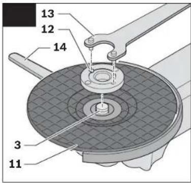
Mounting Grinding or Cutting Discs
(see figures D1 -D2)
Applies for the following types:
-060230440. -06023315..
-060232444,...464,-06023325..
.474,...434 -06023345..
-06023295..
Installation
- Make sure that the fitting protection guard is mounted (see "Mounting the Protective Devices", page 31).
- Place the clamping flange 10 on the grinder spindle 3.
A plastic part (O-ring) is fitted around the centring collar of mounting flange 10. If the O-ring is missing or damaged, it must immediately be replaced before mounting flange 10 is mounted.
- Mount the desired grinding/cutting disc 11 in the correct rotation direction onto the grinder spindle 3.
Bosch Power Tools 1 609 92A 36G | (2.11.16)
32|English
- Place the clamping nut 12 onto the spindle thread so that the central recess of the clamping nut faces upward.
- Tighten the clamping nut with two-pin spanner 13, while counter-holding the spanner surfaces of the grinder spindle 3 with open-end spanner 14.
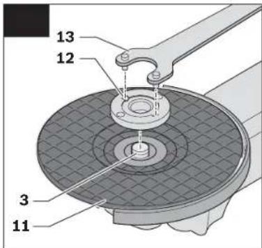
Removal
- Hold the grinder spindle 3 on the spanner surfaces with open-end spanner 14.
- Unscrew the clamping nut 12 from the grinder spindle with two-pin spanner 13, while counter-holding the spanner surfaces with open-end spanner 14.
- Afterwards, pull the grinding tool and the mounting flange from the grinder spindle.
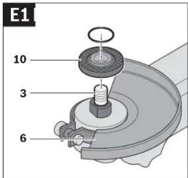
Machines with Spindle Lock Button 5
Applies for the following types:
-060232440.
-0602324434
-060232444.
For machines with spindle lock button 5, counter-holding with an open-end spanner is not required when mounting grinding tools (see figures E1 – E2).
▶ Actuate the spindle lock button only when the grinder spindle is at a standstill. Otherwise, the machine may become damaged.
- Before installing or removing the grinding tool, press and hold spindle lock button 5 to lock the grinder spindle 3 in place.
- Mount the desired grinding tool (see "Mounting Grinding or Cutting Discs", page 31).
- Let go of the spindle lock button 5 to release the locked grinder spindle.
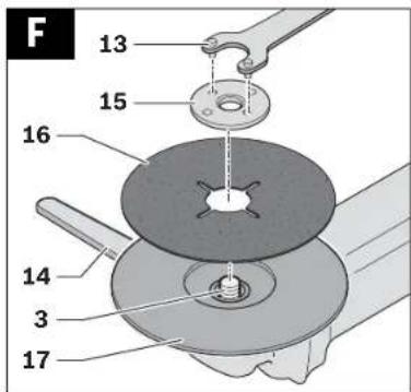
Mounting the Rubber Sanding Plate (see figure F)
Applies for the following types:
-06023014.. -060232440.
-060230540.
-0602306434
Installation
- Make sure that the hand guard and the auxiliary handle are mounted (see "Mounting the Protective Devices", page 31).
- Place the rubber sanding plate 17 onto the grinder spindle 3.
- Lay the sanding disc 16 on the rubber sanding plate.
- Place the round nut 15 on the spindle collar.
- Tighten the round nut with two-pin spanner 13, while counter-holding the spanner surfaces of the grinder spindle 3 with open-end spanner 14.
Take care that the round nut 15 is screwed completely into the bulge of the rubber sanding plate so that it does not interfere while sanding and the sanding disc is firmly seated.
Removal
- Hold the grinder spindle 3 on the spanner surfaces with open-end spanner 14.
- Unscrew the round nut 15 from the grinder spindle with two-pin spanner 13, while counter-holding the spanner surfaces with open-end spanner 14.
– Pull the sanding disc and the rubber sanding plate from the grinder spindle.
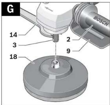
Mounting the Buffing Disc (see figure G)
Applies for the following types:
-06023014.. -060232440.
-060230540.
-0602306434
Installation
Pay attention that the thread of the buffing disc fits exactly on the grinder spindle thread (M14).
- Make sure that the hand guard and the auxiliary handle are mounted (see "Mounting the Protective Devices", page 31).
- Screw the buffing disc 18 so far onto the grinder spindle 3 that it rests firmly against the face surface of the grinder spindle, while counter-holding the spanner surfaces of the grinder spindle 3 with open-end spanner 14.
Removal
- Unscrew the tightly seated buffing disc 18 from the grinder spindle by applying an open-end spanner to the buffing disc spanner surfaces, while counter-holding the spanner surfaces of the grinder spindle 3 with open-end spanner 14.
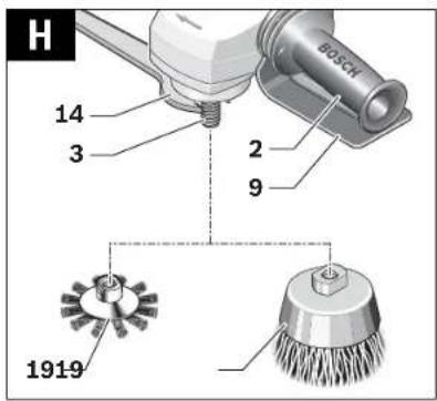
Mounting Wire Brushes (see figure H)
Applies for the following types:
-060230440. -06023315..
-060232444,...464,-06023325..
... 474, ... 434 - 0 602 334 5..
-06023295..
Installation
Pay attention that the thread of the wire brush fits exactly on the grinder spindle thread (M14).
- Make sure that the hand guard and the auxiliary handle are mounted (see "Mounting the Protective Devices", page 31).
- Screw the desired wire brush 19 (cup brush or wire wheel) so far onto the grinder spindle 3 that it rests firmly against the face surface of the grinder spindle, while counter-holding the spanner surfaces of the grinder spindle with open-end spanner 14.
Removal
- Unscrew the tightly seated wire brush 19 from the grinder spindle by applying an open-end spanner to wire brush spanner surfaces, while counter-holding the spanner surfaces of the grinder spindle 3 with open-end spanner 14.
Dust/Chip Extraction
▶ Dusts from materials such as lead-containing coatings, some wood types, minerals and metal can be harmful to one's health. Touching or breathing-in the dusts can cause allergic reactions and/or lead to respiratory infections of the user or bystanders.


English | 33
Certain dusts, such as oak or beech dust, are considered as carcinogenic, especially in connection with wood-treatment additives (chromate, wood preservative). Materials containing asbestos may only be worked by specialists.
- As far as possible, use a dust extraction system suitable for the material.
- Provide for good ventilation of the working place.
- It is recommended to wear a P2 filter-class respirator. Observe the relevant regulations in your country for the materials to be worked.
▶ Prevent dust accumulation at the workplace. Dusts can easily ignite,
Connection to the Power Supply
For operation of the power tools, a frequency converter is required that generates three-phase current with a frequency according to that listed on the type plate.
Frequency converters are available in various sizes, with different frequencies, secondary voltages and rated outputs. The choice of the frequency converter depends on the power tools to be connected. When selecting a frequency converter, contact your Bosch-specialist shop for advice.
The machine is provided with a four meter long specialty cable without plug. To put it into operation, the specialty cable must be equipped with a four-pole CEE plug (identification colour green).
Additionally, the machine can be equipped with a commercially available motor protection switch for protection against overload. The adjustment range of the motor protection switch must cover the nominal current of the power tool (see "Technical Data"). The motor protection switch must react in less than one second.
Please observe the safety warnings and assembly instructions in the operating instructions of the motor protection switch!
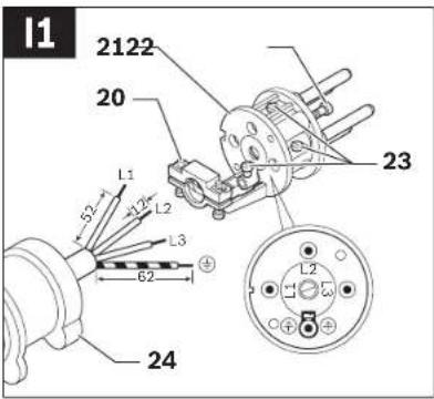
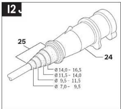
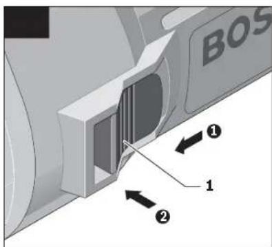
Mounting the CEE Plug (see figures I1 - I2)
- Loosen the two screws 22 and pull the plug insert 21 out of the plug housing of the CEE plug 24.
- Cut off the plastic sleeve 25 according to the diameter of the specialty cable of the power tool and insert the specialty cable through the CEE plug housing.
- Insert the four conductors through the cable strain relief 20.
- Loosen the four small screws 23 in the plug insert 21 and insert
the conductor ferrule of the brown L1 conductor into contact tube L1.
the conductor ferrule of the blue L2 conductor into contact tube L2,
the conductor ferrule of the black L3 conductor into contact tube L3,
and the conductor ferrule of the green/yellow conductor ⊕ into the earthing contact tube ⊖
- Firmly tighten the four small screws 23 in the plug insert 21 to affix the conductors.
- Now, tighten the screws of the cable strain relief 20 so that the cable clamp goes around the complete cable sheath, ensuring that no pressure is on the conductor ferrules.
- Reinsert plug insert 21 into the housing of the CEE plug 24 and tighten both screws 22 again.
– Afterwards, check the proper function of the protective conductor. - Insert the CEE plug 24 of the power tool into the connection socket of the frequency converter.
Now, connect the frequency converter to the power supply. For information on how to connect the frequency converter to the power supply, see the frequency converter operating instructions.
▶ Afterwards, check the rotation direction!
Checking the Rotation Direction
The rotation direction of the grinder spindle must correspond with the arrow on the power tool.
If the grinder spindle rotates in the wrong direction when putting into operation for the first time (see "Switching the Power Tool On/Off", page 34), switch the power tool off immediately and disconnect it from the power supply.
- Loosen the two screws 22 again and pull the plug insert 21 out of the plug housing of the CEE plug 24.
- Loosen the conductor ferrules of the black and brown conductors from their contact tubes.
- Now, insert the conductor ferrule of the black conductor L3 into contact tube L1, and the conductor ferrule of the brown conductor L1 into contact tube L3.
- Firmly tighten the small screws 23 in the plug insert 21 to affix the conductors.
- Reinsert plug insert 21 into the housing of the CEE plug 24 and tighten both screws 22 again.
- Afterwards, check the proper function of the protective conductor.
- Reconnect the power tool to the power supply.
Operation
Starting Operation
The voltage and frequency of the power source must correspond with the data on the type plate of the power tool.
▶ Check grinding tools before using. The grinding tool must be mounted properly and be able to move freely. Carry out a test run for at least one minute with no load. Do not use damaged, out-of-centre or vibrating grinding tools. Damaged grinding tools can burst and cause injuries.
If the machine should unexpectedly stop operating even though the On/Off switch 1 is in the "On" position, set the On/Off switch to "Off". This will prevent uncontrolled restarting of the machine. Before restarting the machine, check the power supply (see "Connection to the Power Supply", page 33).
▶ Always connect the power tool to the frequency converter first, before connecting the frequency converter to the mains supply.
To save energy, only switch the power tool on when using it.

34| English
Switching the Frequency Converter On/Off
The frequency converter must be put into operation first before actuating the power tool.
For this, observe the operating instructions of the frequency converter.
Switching the Power Tool On/Off
with the On/Off Switch (see figure J1)
Applies for the following types:
-06023244..
- To start the machine, push the On/Off switch 1 forwards.
- To lock the On/Off switch 1, press the down at the front until it latches.
- To switch off the power tool, release the On/Off switch 1. When the On/Off switch 1 is locked-on, briefly press it toward the rear and then release it.
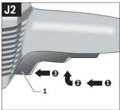
Switching the Power Tool On/Off
with Safety Switch (see figure J2)
Applies for the following types:
-06023014.. -06023295..
-060230440. -06023315..
-060230540. -06023325..
-0602306434 -06023345..
- To start the power tool, press the On/Off switch 1 forward and then down.
- To lock-on the pressed On/Off switch 1, push the On/Off switch 1 further forward.
- To switch off the power tool, release the On/Off switch 1, or when it is locked, briefly press the On/Off switch 1 and then release it.
Working Advice
▶ Disconnect the power supply before making any adjustments, changing accessories, or placing the machine aside. This safety measure prevents accidental starting of the power tool.
Exercise caution when cutting slots in structural walls; see Section "Information on Structures".
▶ Clamp the workpiece if it does not remain stationary due to its own weight.
▶ Do not strain the machine so heavily that it comes to a standstill.
▶ After heavily straining the power tool, continue to run it at no-load for several minutes to cool down the accessory.
Sanding with the Flap Disc
With the flap disc (accessory), curved surfaces and profiles can be worked.
Flap discs have a considerably higher service life, lower noise levels and lower sanding temperatures than conventional sanding sheets.
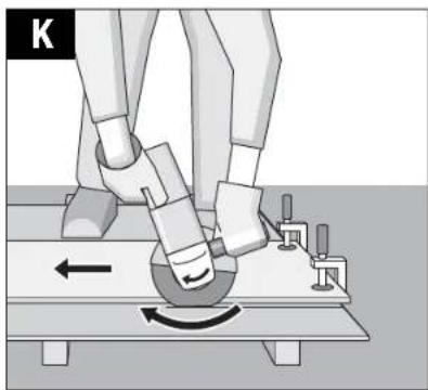
Cutting Metal (see figure K)
For cutting with bonded abrasives, always use a protection guard for cutting.
When cutting, work with moderate feed, adapted to the material being cut. Do not exert pressure onto the cutting disc, tilt or oscillate the machine.
Do not reduce the speed of running down cutting discs by applying sideward pressure.
The machine must always work in an up-grinding motion. Otherwise, the danger exists of it being pushed uncontrolled out of the cut.
When cutting profiles and square bar, it is best to start at the smallest cross section.
Cutting Stone
▶ Provide for sufficient dust extraction when cutting stone.
▶ Wear a dust respirator.
The machine may be used only for dry cutting/grinding.
For cutting stone, it is best to use a diamond cutting disc. For safety against jamming, a special cutting guide with dust extraction protection guard (accessory) must be used.
Operate the machine only with dust extraction and additionally wear a dust protection mask.
The vacuum cleaner must be approved for the extraction of masonry dust. Bosch provides suitable vacuum cleaners.
- Switch on the machine and place the front part of the cutting guide on the workpiece. Slide the machine with moderate feed, adapted to the material to be worked.
For cutting especially hard material, e. g., concrete with high pebble content, the diamond cutting disc can overheat and become damaged as a result. This is clearly indicated by circular sparking, rotating with the diamond cutting disc. In this case, interrupt the cutting process and allow the diamond cutting disc to cool by running the machine for a short time at maximum speed with no load.
Noticeably decreasing work progress and circular sparking are indications of a diamond cutting disc that has become dull. Briefly cutting into abrasive material (e.g. lime-sand brick) can resharpen the disc again.
Information on Structures
Slots in structural walls are subject to the Standard DIN 1053 Part 1, or country-specific regulations.
These regulations are to be observed under all circumstances. Before beginning work, consult the responsible structural engineer, architect or the construction supervisor.
Rough Grinding
▶ Never use a cutting disc for roughing.
The best roughing results are achieved when setting the machine at an angle of 30^ to 40^ . Move the machine back and forth with moderate pressure. In this manner, the workpiece will not become too hot, does not discolour and no grooves are formed.
Sanding with Sanding Discs and the Rubber Sanding Plate The choice of the suitable sanding paper depends on the material to be worked.
Bosch offers various sanding-paper qualities that fit the rubber sanding plate. Contact your specialist shop for advice.
English | 35
Polishing with the Buffing Disc
When polishing, a polishing agent is applied to the buffing disc or the material being polished, and worked into the surface of the material by means of rotation.
When working in several polishing steps, where each polishing agent has a finer grain, a separate buffing pad must be used for each grain size.
Thoroughly clean the surface of the material being worked between each polishing step.
Maintenance and Service
Maintenance and Cleaning
▶ Disconnect the power supply before making any adjustments, changing accessories, or placing the machine aside. This safety measure prevents accidental starting of the power tool.
▶ For safe and proper working, always keep the machine and ventilation slots clean.
In extreme conditions, always use dust extraction as far as possible. Blow out ventilation slots frequently and install a portable residual current device (PRCD). When working metals, conductive dust can settle in the interior of the power tool. The total insulation of the power tool can be impaired.
▶ Regularly measure the no-load speed of the grinder spindle. When the measured value is more than 10 % above or below the specified no-load speed (see "Technical Data"), have the machine checked by an authorised service agent for Bosch power tools. When the no-load speed is too high, the application tool can break; when the no-load speed is too low, the working performance is reduced.
▶ Use only original cables! Before each use, check the power tool, cable and plug for possible damage. Cables and plugs may not be repaired, but must be exchanged in order to avoid danger.
▶ Have maintenance and repair work performed only by qualified specialists. In this manner, it can be ensured that the safety of the power tool is maintained.
Clean the connection sockets, couplers and plugs of the tool, after it has been disconnected from the mains supply, using a dry, lint-free cloth and remove dust and dirt particles.
Clean the gearbox after the first 150 running hours using a mild solvent. Follow the solvent manufacturers directions for use and disposal. Lubricate the gearbox using Bosch gearbox lube. Repeat the lubrication procedure every 300 hours after the initial gearbox service.
An authorized Bosch after-sales service agent will carry out this work quickly and reliably.
If the replacement of the supply cord is necessary, this has to be done by Bosch or an authorized Bosch service agent in order to avoid a safety hazard.
Please store and handle the accessory(-ies) carefully.
Accessories
Information about the complete quality accessory program can be found on the Internet at www.bosch-pt.com and www.boschproductiontools.com or at your dealer.
After-sales Service and Application Service
Our after-sales service responds to your questions concerning maintenance and repair of your product as well as spare parts. Exploded views and information on spare parts can also be found under:
www.bosch-pt.com
Bosch's application service team will gladly answer questions concerning our products and their accessories.
In all correspondence and spare parts orders, please always include the 10-digit article number given on the nameplate of the product.
Great Britain
Robert Bosch Ltd. (B.S.C.)
P.O. Box 98
Broadwater Park
North Orbital Road
Denham
Uxbridge
UB 9 5HJ
At www.bosch-pt.co.uk you can order spare parts or arrange the collection of a product in need of servicing or repair.
Tel. Service: (0344) 7360109
E-Mail: boschservicecentre@bosch.com
Ireland
Origo Ltd.
Unit 23 Magna Drive
Magna Business Park
City West
Dublin 24
Tel. Service: (01) 4666700
Fax: (01) 4666888
Australia, New Zealand and Pacific Islands
Robert Bosch Australia Pty. Ltd.
Power Tools
Locked Bag 66
Clayton South VIC 3169
Customer Contact Center
Inside Australia:
Phone: (01300) 307044
Fax: (01300) 307045
Inside New Zealand:
Phone: (0800) 543353
Fax: (0800) 428570
Outside AU and NZ:
Phone: +61 3 95415555
www.bosch.com.au
Republic of South Africa
Customer service
Hotline: (011) 6519600


36 | Français
Gauteng - BSC Service Centre
35 Roper Street, New Centre
Johannesburg
Tel.: (011) 4939375
Fax: (011) 4930126
E-Mail:bsctools@icon.co.za
KZN - BSC Service Centre
Unit E, Almar Centre
143 Crompton Street
Pinetown
Tel.: (031) 7012120
Fax: (031) 7012446
E-Mail: bsc.dur@za.bosch.com
Western Cape - BSC Service Centre
Democracy Way, Prosperity Park
Milnerton
Tel.: (021) 5512577
Fax:(021)5513223
E-Mail: bsc@zsd.co.za
Bosch Headquarters
Midrand, Gauteng
Tel.: (011) 6519600
Fax: (011) 6519880
E-Mail: rbsa-hq.pts@za.bosch.com
Disposal
The machine, accessories and packaging should be sorted for environmental-friendly recycling.
Do not dispose of power tools into household waste!
Only for EC countries:
According to the European Directive 2012/19/EU for Waste Electrical and Electronic Equipment and its implementation into national right, power tools that are no longer usable must be collected separately and disposed of in an environmentally correct manner.
Subject to change without notice.
Français
Executive Vice President
Engineering
Helmut Heinzelmann
Head of Product Certification
PT/ECS

Robert Bosch Power Tools GmbH
70538 Stuttgart, GERMANY
Stuttgart, 01.01.2017
Montage
Robert Bosch (France) S.A.S.
Executive Vice President Head of Product Certification Engineering PT/ECS
jink Sea i.v. h.w.
Robert Bosch Power Tools GmbH
70538 Stuttgart, GERMANY
Stuttgart, 01.01.2017
Montaje
Executive Vice President
Engineering
Helmut Heinzelmann
Head of Product Certification
PT/ECS

i.v. h=mc
Robert Bosch Power Tools GmbH
70538 Stuttgart, GERMANY
Stuttgart, 01.01.2017
Montagem
Executive Vice President Engineering
Helmut Heinzelmann
Head of Product Certification PT/ECS

Robert Bosch Power Tools GmbH
70538 Stuttgart, GERMANY
Stuttgart, 01.01.2017
94| Italiano
Montaggio
Henk Becker Executive Vice President Engineering Helmut Heinzelmann Head of Product Certification PT/ECS
if we see i.v. h:m
Robert Bosch Power Tools GmbH 70538 Stuttgart, GERMANY Stuttgart, 01.01.2017
Montage
Executive Vice President
Engineering
Helmut Heinzelmann
Head of Product Certification
PT/ECS
juee 200 i.v. h.w.
Robert Bosch Power Tools GmbH
70538 Stuttgart, GERMANY
Stuttgart, 01.01.2017
Montering
Bosch Service Center
Telegrafvej 3
2750 Ballerup
På www.bosch-pt.dk kan der online bestilles reservedele eller oprettes en reparations ordre.
Tlf. Service Center: 44898855
Fax: 44898755
E-Mail: vaerktoej@dk.bosch.com
Bortskaffelse
Henk Becker Executive Vice President Engineering
Helmut Heinzelmann Head of Product Certification PT/ECS

Robert Bosch Power Tools GmbH 70538 Stuttgart, GERMANY Stuttgart, 01.01.2017
Montage
Bosch Service Center
Telegrafvej 3
2750 Ballerup
Danmark
Tel.: (08) 7501820 (inom Sverige)
Fax: (011) 187691
Avfallshantering
Executive Vice President
Engineering
Helmut Heinzelmann
Head of Product Certification
PT/ECS

i.v. k-m
Robert Bosch Power Tools GmbH
70538 Stuttgart, GERMANY
Stuttgart, 01.01.2017
Montering
0
0
0
0
0
0
0
0
0
0
0
0
0
0
0
0
0
0
0
0
0
0
0
0
0
0
0
0
0
0
0
0
0
0
0
0
0
0
0
0
0
0
0
0
0
0
0
0
0
0
0
0
0
0
0
0
0
0
0
0
0
0
0
0
0
0
0
0
0
0
0
0
0
0
0
0
0
0
0
0
0
0
0
0
0
0
0
0
0
0
0
0
0
0
0
0
0
0
0
0
0
0
0
0
0
0
0
0
0
0
0
0


162|Suomi
Executive Vice President Engineering
Helmut Heinzelmann
Head of Product Certification PT/ECS


Robert Bosch Power Tools GmbH
70538 Stuttgart, GERMANY
Stuttgart, 01.01.2017
Asennus
OBI_BUCH-2487-002.book Page 176 Wednesday, November 2, 2016 4:43 PM
Henk Becker Executive Vice President Engineering Helmut Heinzelmann Head of Product Certification PT/ECS
Aur Seo i.V. H.W.
Robert Bosch Power Tools GmbH 70538 Stuttgart, GERMANY Stuttgart, 01.01.2017
Συναρμολόγηση
OBJ_BUCH-2487-002.book Page 191 Wednesday, November 2, 2016 4:43 PM
Henk Becker Executive Vice President Engineering
Helmut Heinzelmann Head of Product Certification PT/ECS

Robert Bosch Power Tools GmbH 70538 Stuttgart, GERMANY Stuttgart, 01.01.2017
Montaj
OBI_BUCH-2487-002.book Page 206 Wednesday, November 2, 2016 4:43 PM
Executive Vice President Engineering
Helmut Heinzelmann
Head of Product Certification PT/ECS

i.v. k=mc
Robert Bosch Power Tools GmbH 70538 Stuttgart, GERMANY Stuttgart, 01.01.2017
210 | Polski
Montaż
Robert Bosch Sp. z o.o.
Henk Becker Executive Vice President Engineering
Helmut Heinzelmann Head of Product Certification PT/ECS


Robert Bosch Power Tools GmbH 70538 Stuttgart, GERMANY Stuttgart, 01.01.2017
Montáž
Bosch Service Center PT
KVápence 1621/16
692 01 Mikulov
m = 311
广力云智慧零售收银系统
[Non-Text]
[Non-Text]
[Non-Text]
[Non-Text]
[Non-Text]
[Non-Text]
[Non-Text]
[Non-Text]
[Non-Text]
[Non-Text]
[Non-Text]
[Non-Text]
[Non-Text]
[Non-Text]
[Non-Text]
[Non-Text]
[Non-Text]
[Non-Text]
[Non-Text]
[Non-Text]
[Non-Text]
[Non-Text]
[Non-Text]
[Non-Text]
[Non-Text]
[Non-Text]
[Non-Text]
[Non-Text]
[Non-Text]
[Non-Text]
[Non-Text]
[Non-Text]
[Non-Text]
[Non-Text]
[Non-Text]
[Non-Text]
[Non-Text]
[Non-Text]
[Non-Text]
[Non-Text]
[Non-Text]
[Non-Text]
[Non-Text]
[Non-Text]
[Non-Text]
[Non-Text]
[Non-Text]
[Non-Text]
[Non-Text]
-
-
X
-
-
[Unreadable]
[Unreadable]
E
[Unreadable]
[Non-Text]
[Non-Text]
[Non-Text]
[Non-Text]
[Non-Text]
[Non-Text]
[Non-Text]
[Non-Text]
[Non-Text]
[Non-Text]
[Non-Text]
[Non-Text]
[Non-Text]
[Non-Text]
[Non-Text]
[Non-Text]
[Non-Text]
[Non-Text]
[Non-Text]
[Non-Text]
[Non-Text]
[Non-Text]
[Non-Text]
[Non-Text]
[Non-Text]
[Non-Text]
[Non-Text]
[Non-Text]
[Non-Text]
[Non-Text]
[Non-Text]
[Non-Text]
[Non-Text]
[Non-Text]
[Non-Text]
[Non-Text]
[Non-Text]
[Non-Text]
[Non-Text]
-
[Non-Text]
[Non-Text]
[Non-Text]
[Non-Text]
[Non-Text]
[Non-Text]
[Non-Text]
[Non-Text]
[Non-Text]
[Non-Text]
[Non-Text]
[Non-Text]
[Non-Text]
[Non-Text]
[Non-Text]
[Non-Text]
[Non-Text]
[Non-Text]
[Non-Text]
[Non-Text]
[Non-Text]
[Non-Text]
[Non-Text]
[Non-Text]
[Non-Text]
[Non-Text]
[Non-Text]
[Non-Text]
[Non-Text]
[Non-Text]
[Non-Text]
[Non-Text]
[Non-Text]
[Non-Text]
[Non-Text]
[Non-Text]
[Non-Text]
[Non-Text]
。
The image is too blurry to recognize any text content.
图
•
[Non-Text]
-
[Non-Text]
+
•
[Non-Text]
[Non-Text]
[Non-Text]
[Non-Text]
[Non-Text]
[Non-Text]
[Non-Text]
[Non-Text]
[Non-Text]
[Non-Text]
[Non-Text]
[Non-Text]
[Non-Text]
[Non-Text]
[Non-Text]
[Non-Text]
[Non-Text]
[Non-Text]
[Non-Text]
[Non-Text]
[Non-Text]
[Non-Text]
[Non-Text]
[Non-Text]
[Non-Text]
[Non-Text]
[Non-Text]
[Non-Text]
[Non-Text]
[Non-Text]
[Non-Text]
[Non-Text]
[Non-Text]
[Non-Text]
[Non-Text]
[Non-Text]
[Non-Text]
[Non-Text]
[Non-Text]
[Non-Text]
[Non-Text]
[Non-Text]
[Non-Text]
100
10
[Non-Text]
[Table_Title]
20
90
5.7
53
2
3
m = 311
广力云智慧零售收银系统
[Non-Text]
[Non-Text]
[Non-Text]
[Non-Text]
[Non-Text]
[Non-Text]
[Non-Text]
[Non-Text]
[Non-Text]
Henk Becker Executive Vice President Engineering
Helmut Heinzelmann Head of Product Certification PT/ECS

Robert Bosch Power Tools GmbH 70538 Stuttgart, GERMANY Stuttgart, 01.01.2017
Montáž
OBI_BUCH-2487-002.book Page 251 Wednesday, November 2, 2016 4:43 PM
Henk Becker Executive Vice President Engineering
Helmut Heinzelmann Head of Product Certification PT/ECS

Robert Bosch Power Tools GmbH 70538 Stuttgart, GERMANY Stuttgart, 01.01.2017
Összeszerelés
OBJ_BUCH-2487-002.book Page 259 Wednesday, November 2, 2016 4:43 PM
Magyar|259
Executive Vice President
Engineering
Helmut Heinzelmann
Head of Product Certification
PT/ECS

Robert Bosch Power Tools GmbH
70538 Stuttgart, GERMANY
Stuttgart, 01.01.2017
Сборка
OBJ_BUCH-2487-002.book Page 284 Wednesday, November 2, 2016 4:43 PM
Henk Becker Executive Vice President Engineering Helmut Heinzelmann Head of Product Certification PT/ECS

Robert Bosch Power Tools GmbH 70538 Stuttgart, GERMANY Stuttgart, 01.01.2017
Монтаж
Henk Becker Executive Vice President Engineering
Helmut Heinzelmann Head of Product Certification PT/ECS
jus Sea i.v. h.w.
Robert Bosch Power Tools GmbH 70538 Stuttgart, GERMANY Stuttgart, 01.01.2017
304|Казакша
Жинау
Executive Vice President Engineering
Helmut Heinzelmann
Head of Product Certification PT/ECS

Robert Bosch Power Tools GmbH
70538 Stuttgart, GERMANY
Stuttgart, 01.01.2017
Română|319
Montare
Tel. service scule electrice: (021) 4057540
Fax:(021)4057566
E-Mail: infoBSC@ro.bosch.com
Henk Becker Executive Vice President Engineering
Helmut Heinzelmann Head of Product Certification PT/ECS
A. 300 i.v. h.m.
Robert Bosch Power Tools GmbH 70538 Stuttgart, GERMANY Stuttgart, 01.01.2017
Монтиране
Executive Vice President
Engineering
Helmut Heinzelmann
Head of Product Certification
PT/ECS

i.v. k·w
Robert Bosch Power Tools GmbH
70538 Stuttgart, GERMANY
Stuttgart, 01.01.2017
Монтажа
OBJ_BUCH-2487-002.hook Page 351 Wednesday, November 2, 2016 4:43 PM
Македренски | 351
m = 311
m = 311
[Non-Text]
[Non-Text]
[Non-Text]
[Non-Text]
[Non-Text]
[Non-Text]
[Non-Text]
[Non-Text]
[Non-Text]
[Non-Text]
[Non-Text]
[Non-Text]
[Non-Text]
[Non-Text]
[Non-Text]
[Non-Text]
[Non-Text]
[Non-Text]
[Non-Text]
[Non-Text]
[Non-Text]
[Non-Text]
[Non-Text]
[Non-Text]
[Non-Text]
[Non-Text]
[Non-Text]
1
m = 311
m = 311
+
1
[Unreadable]
[Unreadable]
2014
Srpski|361
Visokofrekventna ugaona brusilica
| Broj artikla | 0 602 306 ... | 0 602 324 ... | ||||
| ... 434 | ... 401 | ... 404 | ... 407 | ... 434 | ||
| Nominalni napon | V | 2 | 0 | 0 | 265 135 72 200 | |
| Frekvencija | Hz 300 200 200 200 300 | |||||
| Nominalna primljena snaga | W | 1 | 4 | 5 | 0 | 520 520 520 800 |
| Nominalna predana snaga | W | 1 | 0 | 5 | 0 | 360 360 360 550 |
| Nominalna struja | A | 5,5 | 1,6 | 3,2 | 6,0 | 3,2 |
| Broj obrtaja na prazno | min^-1 | 1700 | 4900 | 4900 | 4900 | 7300 |
| maks. prečnik brusnih ploča | mm 175 125 125 125 125 | |||||
| Navoj brusnog vretena | M14 | M14 | M14 | M14 | M14 | |
| Težina prema EPTA-Procedure 01:2014– sa dodatnom drškom i prigušenimvibracijama | kg | 4,8 | 2,3 | 2,3 | 2,3 | 2,5 |
| Klasa zaštite | # /T | # /T | # /T | # /T | # /T | |
| Vrsta zaštite | IP 20 | IP 20 | IP 20 | IP 20 | IP 20 | |
Visokofrekventna ugaona brusilica
| Broj artikla | 0 602 324 ... | ||||
| ... 441 | ... 444 | ... 447 | ... 474 | ||
| Nominalni napon | V | 265 | 135 | 72 | 135 |
| Frekvencija | Hz | 200 | 200 | 200 | 200 |
| Nominalna primljena snaga | W | 520 | 520 | 520 | 520 |
| Nominalna predana snaga | W | 360 | 360 | 360 | 360 |
| Nominalna struja | A | 1,6 | 3,2 | 6,0 | 3,2 |
| Broj obrtaja na prazno | min^1 | 5850 | 5850 | 5850 | 6850 |
| maks. prečnik brusnih ploča | mm | 125 | 125 | 125 | 125 |
| Navoj brusnog vretena | M14 | M14 | M14 | M14 | |
| Težina prema EPTA-Procedure 01:2014 - sa dodatnom drškom i prigušenim vibracijama | kg | 2,5 | 2,5 | 2,5 | 2,5 |
| Klasa zaštite | ⊕ /I | ⊕ /I | ⊕ /I | ⊕ /I | |
| Vrsta zaštite | IP 20 | IP 20 | IP 20 | IP 20 | |
Visokofrekventna ugaona brusilica
| Broj artikla | 0 602 329 ... | ||
| ...501 | ...534 | ||
| Nominalni napon | V | 265 | 2 |
| Frekvencija | Hz | 200 | 300 |
| Nominalna primljena snaga | W | 1200 | 1800 |
| Nominalna predana snaga | W | 1000 | 1500 |
| Nominalna struja | A | 3,3 | 6,4 |
| Broj obrtaja na prazno | min ^-1 | 8480 | 8480 |
| maks. prečnik brusnih ploča | mm | 180 | 180 |
| Navoj brusnog vretena | M14 | M14 | |
| Težina prema EPTA-Procedure 01:2014– sa dodatnom drškom i prigušenim vibracijama | kg | 5,8 | 5,8 |
| Klasa zaštite | ⏻/I | ⏻/I | |
| Vrsta zaštite | IP 20 | IP 20 | |
Bosch Power Tools 1 609 92A 36G | (2.11.16)
362 | Srpski
Visokofrekventna ugaona brusilica
| Broj artikla | 0 602 331 ... | ||||
| ...501 | ...504 | ...507 | ...534 | ||
| Nominalni napon | V 265 135 72 200 | ||||
| Frekvencija | Hz 200 200 200 300 | ||||
| Nominalna primljena snaga | W 1950 1950 1950 2900 | ||||
| Nominalna predana snaga | W 1500 1500 1500 2200 | ||||
| Nominalna struja | A | 5 | 10 18 10 | ||
| Broj obrtaja na prazno | min ^-1 | 8480 8480 8480 8480 | |||
| maks. prečnik brusnih ploča | mm 180 180 180 180 | ||||
| Navoj brusnog vretena | M14 M14 M14 M14 | ||||
| Težina prema EPTA-Procedure 01:2014– sa dodatnom drškom i prigušenimvibracijama | kg 7,1 7,1 7,1 7,1 | ||||
| Klasa zaštite | ⊕ /T /I /I /I | ⊕ | ⊕ | ⊕ | |
| Vrsta zaštite | IP 20 | IP 20 | IP 20 | IP 20 | |
Visokofrekventna ugaona brusilica
| Broj artikla | 0 602 332 ... | |||||
| ...501 | ...504 | ...507 | ...534 | ...511 | ||
| Nominalni napon | V | 265 | 135 | 72 | 200 | 72 |
| Frekvencija | Hz | 200 | 200 | 200 | 300 | 300 |
| Nominalna primljena snaga | W | 1950 | 1950 | 1950 | 2900 | 2900 |
| Nominalna predana snaga | W | 1500 | 1500 | 1500 | 2200 | 2200 |
| Nominalna struja | A | 5 | 10 | 18 | 10 | 27 |
| Broj obrtaja na prazno | min^-1 | 6600 | 6600 | 6600 | 6600 | 6600 |
| maks. prečnik brusnih ploča | mm | 230 | 230 | 230 | 230 | 230 |
| Navoj brusnog vretena | M14 | M14 | M14 | M14 | M14 | |
| Težina prema EPTA-Procedure 01:2014– sa dodatnom drškom i prigušenim vibracijama | kg | 7,1 | 7,1 | 7,1 | 7,1 | 7,1 |
| Klasa zaštite | /1 | /1 | /1 | /1 | /1 | |
| Vrsta zaštite | IP 20 | IP 20 | IP 20 | IP 20 | IP 20 | |
Visokofrekventna ugaona brusilica
| Broj artikla | 0 602 334 ... | ||||
| ...501 | ...504 | ...507 | ...534 | ||
| Nominalni napon | V 265 135 72 200 | ||||
| Frekvencija | Hz 200 200 200 300 | ||||
| Nominalna primljena snaga | W 2500 2500 2500 3800 | ||||
| Nominalna predana snaga | W 2200 2200 2200 3100 | ||||
| Nominalna struja | A | 6,7 | 13,2 | 24,7 | 13,2 |
| Broj obrtaja na prazno | min ^-1 | 6600 6600 6600 6600 | |||
| maks. prečnik brusnih ploča | mm 230 230 230 230 | ||||
| Navoj brusnog vretena | M14 M14 M14 M14 | ||||
| Težina prema EPTA-Procedure 01:2014– sa dodatnom drškom i prigušenim vibracijama | kg | 7,8 | 7,8 | 7,8 | 7,8 |
| Klasa zaštite | ⊕ /I /I /I /I | ||||
1 609 92A.36G | (2.11.16) Bosch Power Tools
Srpski|363
| Visokofrekventna ugaona brusilica | ||||
| Vrsta zaštite | IP 20 | IP 20 | IP 20 | |
| Napomene o napajanjuElektrični uredaj je deo visokofrekventnog sistema i zahteva trofaznu naizmeničnu struju sa frekvencijom koja odgovara oznaci na pločici uredaja. | Da bi se ta frekvencija postigla, električni alat mora da bude povezan sa frekventnim pretvaračem (pogledajte „Priključak na snabdevanje energijom”, strana 367). | |||
Executive Vice President
Engineering
Helmut Heinzelmann
Head of Product Certification
PT/ECS

i.v. k·w
Robert Bosch Power Tools GmbH
70538 Stuttgart, GERMANY
Stuttgart, 01.01.2017
Montaža
Montaža zaštitnih uredjaja
Opšta uputstva
Executive Vice President
Engineering
Helmut Heinzelmann
Head of Product Certification
PT/ECS

Robert Bosch Power Tools GmbH
70538 Stuttgart, GERMANY
Stuttgart, 01.01.2017
Montaža
Executive Vice President Engineering
Helmut Heinzelmann
Head of Product Certification PT/ECS

i.v. h·w—
Robert Bosch Power Tools GmbH 70538 Stuttgart, GERMANY Stuttgart, 01.01.2017
Henk Becker Executive Vice President Engineering
Helmut Heinzelmann Head of Product Certification PT/ECS
if we see i.v. h:mc
Robert Bosch Power Tools GmbH 70538 Stuttgart, GERMANY Stuttgart, 01.01.2017
Montaž
Staatikaalased juhised
Executive Vice President Engineering
Helmut Heinzelmann
Head of Product Certification PT/ECS

i.v. k-m
Robert Bosch Power Tools GmbH
70538 Stuttgart, GERMANY
Stuttgart, 01.01.2017
Latviešu|421
Montāža
Aizsargieriču nostiprinăšana
Executive Vice President
Engineering
Helmut Heinzelmann
Head of Product Certification
PT/ECS

i.v. k=mc
Robert Bosch Power Tools GmbH
70538 Stuttgart, GERMANY
Stuttgart, 01.01.2017
436 | Lietuviškai
Montavimas
Senior Vice President
Engineering
Helmut Heinzelmann
Head of Product Certification
PT/ECS


Robert Bosch Power Tools GmbH,
70538 Stuttgart, GERMANy
Stuttgart, 01.01.2017
Senior Vice President
Engineering
Helmut Heinzelmann
Head of Product Certification
PT/ECS


Robert Bosch Power Tools GmbH,
70538 Stuttgart, GERMANy
Stuttgart, 01.01.2017
| سئگ فرز فركانس بالا | ||||||||||
| ... 474 | ... 447 | ... 444 | 0 602 324 ... ... 441 | شماره فنى | ||||||
| 135 | 72 | 135 | 265 | V | ولتاز نامی | |||||
| 200 | 200 | 200 | 200 | Hz | فرکانس | |||||
| 520 | 520 | 520 | 520 | W | قدرت ورودی نامی | |||||
| 360 | 360 | 360 | 360 | W | قدرت خروجی نامی | |||||
| 1,63,26,03,27,28,29,30,31,32,33,34,35,36,37,38,39,40,41,42,43,44,45,46,47,48,49,50,51,52,53,54,55,56,57,58,59,60,61,62,63,64,65,66,67,68,69,70,71,72,73,74,75,76,77,78,79,80,81,82,83,84,85,86,87,88,89,90,91,92,93,94,95,96,97,98,99,100,101,102,103,104,105,106,107,108,109,110,111,112,113,114,115,116,117,118,119,120,121,122,123,124,125,126,127,128,129,130,131,132,133,134,135,136,137,138,139,140,141,142,143,144,145,146,147,148,149,150,151,152,153,154,155,156,157,158,159,160,161,162,163,164,165,166,167,168,169,170,171,172,173,174,175,176,177,178,179,180,181,182,183,184,185,186,187,188,189,190,191,192,193,194,195,196,197,198,199,200,201,202,203,204,205,206,207,208,209,210,211,212,213,214,215,216,217,218,219,220,221,222,223,224,225,226,227,228,229,230,231,232,233,234,235,236,237,238,239,240,241,242,243,244,245,246,247,248,249,250,251,252,253,254,255,256,257,258,259,260,261,262,263,264,265,266,267,268,269,270,271,272,273,274,275,276,277,278,279,280,281,282,283,284,285,286,287,288,289,290,291,292,293,294,295,296,297,298,299,300,301,302,303,304,305,306,307,308,309,310,311,312,313,314,315,316,317,318,319,320,321,322,323,324,325,326,327,328,329,330,331,332,333,334,335,336,337,338,339,340,341,342,343,344,345,346,347,348,349,350,351,352,353,354,355,356,357,358,359,360,361,362,363,364,365,366,367,368,369,370,371,372,373,374,375,376,377,378,379,380,381,382,383,384,385,386,387,388,389,390,391,392,393,394,395,396,397,398,399,400,401,402,403,404,405,406,407,408,409,410,411,412,413,414,415,416,417,418,419,420,421,422,423,424,425,426,427,428,429,430,431,432,433,434,435,436,437,438,439,440,441,442,443,444,445,446,447,448,449,450,451,452,453,454,455,456,457,458,459,460,461,462,463,464,465,466,467,468,469,470,471,472,473,474,475,476,477,478,479,480,481,482,483,484,485,486,487,488,489,490,491,492,493,494,495,496,497,498,499,500,501,502,503,504,505,506,507,508,509,510,511,512,513,514,515,516,517,518,519,520,521,522,523,524,525,526,527,528,529,530,531,532,533,534,535,536,537,538,539,540,541,542,543,544,545,546,547,548,549,550,551,552,553,554,555,556,557,558,559,560,561,562,563,564,565,566,567,568,569,570,571,572,573,574,575,576,577,578,579,580,581,582,583,584,585,586,587,588,589,590,591,592,593,594,595,596,597,598,599,600,601,602,603,604,605,606,607,608,609,610,611,612,613,614,615,616,617,618,619,620,621,622,623,624,625,626,627,628,629,630,631,632,633,634,635,636,637,638,639,640,641,642,643,644,645,646,647,648,649,650,651,652,653,654,655,656,657,658,659,660,661,662,663,664,665,666,667,668,669,670,671,672,673,674,675,676,677,678,679,680,681,682,683,684,685,686,687,688,689,690,691,692,693,694,695,696,697,698,699,700,701,702,703,704,705,706,707,708,709,710,711,712,713,714,715,716,717,718,719,720,721,722,723,724,725,726,727,728,729,730,731,732,733,734,735,736,737,738,739,740,741,742,743,744,745,746,747,748,749,750,751,752,753,754,755,756,757,758,759,760,761,762,763,764,765,766,767,768,769,770,771,772,773,774,775,776,777,778,779,780,781,782,783,784,785,786,787,788,789,790,791,792,793,794,795,796,797,798,799,800,801,802,803,804,805,806,807,808,809,810,811,812,813,814,815,816,817,818,819,820,821,822,823,824,825,826,827,828,829,830,831,832,833,834,835,836,837,838,839,840,841,842,843,844,845,846,847,848,849,850,851,852,853,854,855,856,857,858,859,860,861,862,863,864,865,866,867,868,869,870,871,872,873,874,875,876,877,878,879,880,881,882,883,884,885,886,887,888,889,890,891,892,893,894,895,896,897,898,899,900,901,902,903,904,905,906,907,908,909,910,911,912,913,914,915,916,917,918,919,920,921,922,923,924,925,926,927,928,929,930,931,932,933,934,935,936,937,938,939,940,941,942,943,944,945,946,947,948,949,950,951,952,953,954,955,956,957,958,959,960,961,962,963,964,965,966,967,968,969,970,971,972,973,974,975,976,977,978,979,980,981,982,983,984,985,986,987,988,989,990,991,992,993,994,995,996,997,998,999,100 | ||||||||||
| 6 850 | 5 850 | 5 850 | 5 850 | -1 | سرعت در حالت آزادmin | |||||
| 125 | 125 | 125 | 125 | mm | حداڭثر قطر صفمه ساب | |||||
| M14 | M14 | M14 | M14 | ززوه محور دستگاه | ||||||
| 2.5 | 2.5 | 2.5 | 2.5 | kg | وزن مطابق استانداردEPTA-Procedure 01:2014با دسته کمکی کاهنده لرزش | |||||
| ‡ | ‡ | ‡ | ‡ | کلاس ايمني/۱/۱/۱/۱/۱/۱/۱/۱/۱/۱/۱/۱/۱/۱/۱/۱/۱/۱/۱/۱/۱/۱/۱/۱/۱/۱/۱/۱/۱/۱/۱/۱/۱/۱ | ||||||
| IP 20IP 20IP 20IP 20 | نوع/درجه ايمني | |||||||||
467 | فارسی
اجزاء دستگاه