
HWS 77180 Professional - Angle grinder BOSCH - Free user manual and instructions
Find the device manual for free HWS 77180 Professional BOSCH in PDF.
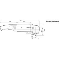


| Brand | Bosch |
| Model | HWS 77180 Professional |
| Product type | Angle grinder |
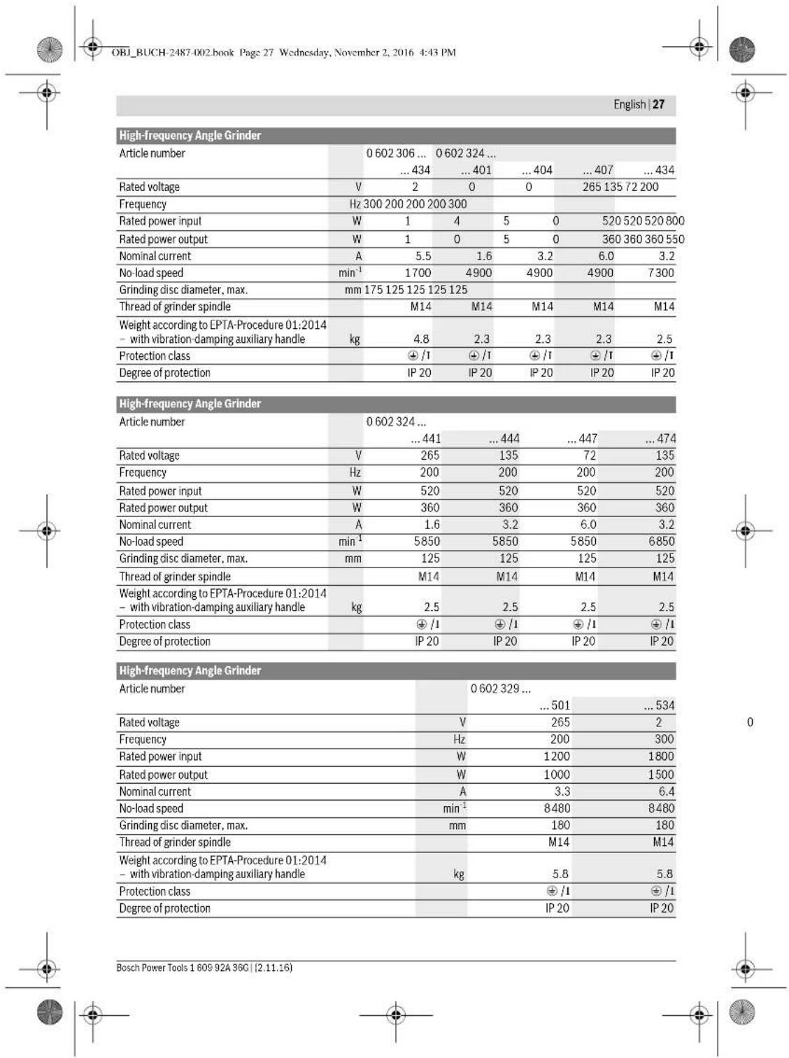
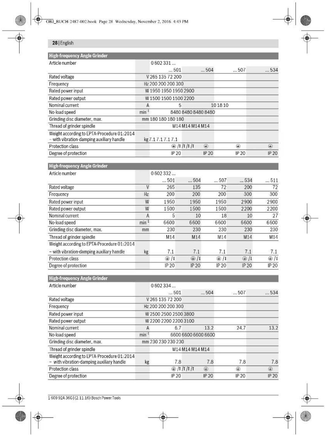
| Power supply | Three-phase high frequency (200-300 Hz, 200-265 V depending on model) |
| No-load speed | Up to 9500 rpm depending on model |
| Power input | Up to 900 W depending on model |
| Max. grinding wheel diameter | 180 mm |
| Spindle thread | M14 |
| Weight | Approx. 2.5 kg (depending on model) |
| Main functions | Grinding, cutting, sanding, brushing, polishing |
| Safety guards | Adjustable protective guard, hand guard, additional anti-vibration handle |
| Sound pressure level | 72-87 dB(A) depending on model |
| Vibration level (grinding) | 5.35-7 m/s² depending on model |
| Maintenance and cleaning | Clean ventilation slots regularly, use a vacuum cleaner, check no-load speed |
| Spare parts | Use only genuine Bosch parts |
| Repairability | Repair by qualified personnel only |
| General information | Instruction manual available in several languages |
Frequently Asked Questions - HWS 77180 Professional BOSCH
User questions about HWS 77180 Professional BOSCH
0 question about this device. Answer the ones you know or ask your own.
Ask a new question about this device
Download the instructions for your Angle grinder in PDF format for free! Find your manual HWS 77180 Professional - BOSCH and take your electronic device back in hand. On this page are published all the documents necessary for the use of your device. HWS 77180 Professional by BOSCH.
USER MANUAL HWS 77180 Professional BOSCH
Robert Bosch Power Tools GmbH
70538 Stuttgart
GERMANY
www.bosch-pt.com
160992A36G (2015.07) MS/473 EURO
1609 92A 36G
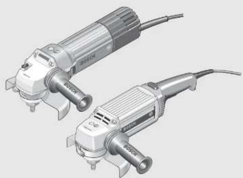
HWS
06023014, 060230440, 060230540, 060230643, 06023244.
06023295, 106023315, 106023325, 106023345.

BOSCH
Original instructions
Notice originale
Manual original
Manual original
2
1
Ta 15015(ain)





Deutsch|7
Deutsch
OBI_BUCH-2487-002.book Page 16 Wednesday, November 2, 2016 4:43 PM
16 | Deutsch
Executive Vice President
Head of Product Certification
Engineering
PT/ECS
f( 2) = h · d
Robert Bosch Power Tools GmbH
70538 Stuttgart, GERMANY
Stuttgart, 01.01.2017
Assembly
General Power Tool Safety Warnings
WARNING: Read all safety warnings and all instructions. Failure to follow the warnings and instructions may result in electric shock, fire and/or serious injury.
Save all warnings and instructions for future reference. The term "power tool" in the warnings refers to your mains-operated (corded) power tool or battery-operated (cordless) power tool.
Work area safety
- Keep work area clean and well lit. Cluttered or dark areas invite accidents. Do not operate power tools in explosive atmospheres, such as in the presence of flammable liquids, gases or dust. Power tools create sparks which may ignite the dust or fumes.
- Keep children and bystanders away while operating a power tool. Distractions can cause you to lose control.
Electrical safety
Power tool plugs must match the outlet. Never modify the plug in any way. Do not use any adapter plugs with earthed (grounded) power tools. Unmodified plugs and matching outlets will reduce risk of electric shock. Avoid body contact with earthed or grounded surfaces, such as pipes, radiators, ranges and refrigerators. There is an increased risk of electric shock if your body is earthed or grounded. Do not expose power tools to rain or wet conditions. Water entering a power tool will increase the risk of electric shock. Do not abuse the cord. Never use the cord for carrying, pulling or unplugging the power tool. Keep cord away from heat, oil, sharp edges and moving parts. Damaged or entangled cords increase the risk of electric shock. When operating a power tool outdoors, use an extension cord suitable for outdoor use. Use of a cord suitable for outdoor use reduces the risk of electric shock.
If operating a power tool in a damp location is unavoidable, use a residual current device (RCD) protected supply. Use of an RCD reduces the risk of electric shock.
Personal safety
Stay alert, watch what you are doing and use common sense when operating a power tool. Do not use a power tool while you are tired or under the influence of drugs, alcohol or medication. A moment of inattention while operating power tools may result in serious personal injury. Use personal protective equipment. Always wear eye protection. Protective equipment such as dust mask, non-skid safety shoes, hard hat, or hearing protection used for appropriate conditions will reduce personal injuries. Prevent unintentional starting. Ensure the switch is in the off-position before connecting to power source and/or battery pack, picking up or carrying the tool. Carrying power tools with your finger on the switch or energising power tools that have the switch on invites accidents. Remove any adjusting key or wrench before turning the power tool on. A wrench or a key left attached to a rotating part of the power tool may result in personal injury. Do not overreach. Keep proper footing and balance at all times. This enables better control of the power tool in unexpected situations. Dress properly. Do not wear loose clothing or jewellery. Keep your hair, clothing and gloves away from moving parts. Loose clothes, jewellery or long hair can be caught in moving parts. If devices are provided for the connection of dust extraction and collection facilities, ensure these are connected and properly used. Use of dust collection can reduce dust-related hazards.
Power tool use and care
Do not force the power tool. Use the correct power tool for your application. The correct power tool will do the job better and safer at the rate for which it was designed. Do not use the power tool if the switch does not turn it on and off. Any power tool that cannot be controlled with the switch is dangerous and must be repaired. Disconnect the plug from the power source and/or the battery pack from the power tool before making any adjustments, changing accessories, or storing power tools. Such preventive safety measures reduce the risk of starting the power tool accidentally. Store idle power tools out of the reach of children and do not allow persons unfamiliar with the power tool or these instructions to operate the power tool. Power tools are dangerous in the hands of untrained users. Maintain power tools. Check for misalignment or binding of moving parts, breakage of parts and any other condition that may affect the power tool's operation. If damaged, have the power tool repaired before use. Many accidents are caused by poorly maintained power tools.




- Keep cutting tools sharp and clean. Properly maintained cutting tools with sharp cutting edges are less likely to bind and are easier to control. Use the power tool, accessories and tool bits etc. in accordance with these instructions, taking into account the working conditions and the work to be performed. Use of the power tool for operations different from those intended could result in a hazardous situation.
Service
Have your power tool serviced by a qualified repair person using only identical replacement parts. This will ensure that the safety of the power tool is maintained.
Safety Warnings for Angle Grinder
Safety warnings common for sanding with sanding discs and polishing
Applies for the following types:
-06023014.. -060230540 -0602306434 -060232440.
This power tool is to be used as a sander and polisher. Observe all safety warnings, instructions, illustrations and data supplied with the power tool. Non-observation of the following instructions can lead to electric shock, fire and/or serious injury. Operations such as grinding, wire brushing or cutting off are not recommended to be performed with this power tool. Operations for which the power tool was not designed may create a hazard and cause personal injury.
Safety warnings common for grinding, working with wire brushes and cut-off grinding
Applies for the following types:
-060230440 -060232444,..464,..474,..434 -06023295.. -06023315.. -06023325.. -06023345..
This power tool is to be used as a grinder, wire brush and cut off grinder. Observe all safety warnings, instructions, illustrations and data supplied with the power tool. Non-observation of the following instructions can lead to electric shock, fire and/or serious injury. Operations such as sanding or polishing are not recommended to be performed with this power tool. Operations for which the power tool was not designed may create a hazard and cause personal injury.
Safety warnings that are common for grinding, sanding, wire brushing, polishing and abrasive cutting off operations
Applies for all types
Do not use accessories which are not specifically designed and recommended by the tool manufacturer. Just because the accessory can be attached to your power tool, it does not assure safe operation.
The rated speed of the accessory must be at least equal to the maximum speed marked on the power tool. Accessories running faster than their rated speed can break and fly apart. The outside diameter and the thickness of your accessory must be within the capacity rating of your power tool. Incorrectly sized accessories cannot be adequately guarded or controlled. Threaded mounting of accessories must match the grinder spindle thread. For accessories mounted by flanges, the arbor hole of the accessory must fit the locating diameter of the flange. Accessories that do not match the mounting hardware of the power tool will run out of balance, vibrate excessively and may cause loss of control. Do not use a damaged accessory. Before each use, inspect the accessory such as abrasive wheels for chips and cracks, backing pad for cracks, tear or excess wear, wire brush for loose or cracked wires. If power tool or accessory is dropped, inspect for damage or install an undamaged accessory. After inspecting and installing an accessory, position yourself and bystanders away from the plane of the rotating accessory and run the power tool at maximum no-load speed for one minute. Damaged accessories will normally break apart during this test time. Wear personal protective equipment. Depending on application, use face shield, safety goggles or safety glasses. As appropriate, wear dust mask, hearing protectors, gloves and shop apron capable of stopping small abrasive or workpiece fragments. The eye protection must be capable of stopping flying debris generated by various operations. The dust mask or respirator must be capable of filtrating particles generated by your operation. Prolonged exposure to high intensity noise may cause hearing loss. Keep bystanders a safe distance away from work area. Anyone entering the work area must wear personal protective equipment. Fragments of workpiece or of a broken accessory may fly away and cause injury beyond immediate area of operation. Hold the power tool by insulated gripping surfaces only, when performing an operation where the cutting accessory may contact hidden wiring or its own cord. Cutting accessory contacting a "live" wire may make exposed metal parts of the power tool "live" and could give the operator an electric shock. Position the cord clear of the spinning accessory. If you lose control, the cord may be cut or snagged and your hand or arm may be pulled into the spinning wheel. Never lay the power tool down until the accessory has come to a complete stop. The spinning wheel may grab the surface and pull the power tool out of your control. Do not run the power tool while carrying it at your side. Accidental contact with the spinning accessory could snag your clothing, pulling the accessory into your body.

Regularly clean the power tool's air vents. The motor's fan will draw the dust inside the housing and excessive accumulation of powdered metal may cause electrical hazards. Do not operate the power tool near flammable materials. Sparks could ignite these materials. Do not use accessories that require liquid coolants. Using water or other liquid coolants may result in electrocution or shock.
Kickback and related warnings
Kickback is a sudden reaction to a pinched or snagged rotating wheel, backing pad, brush or any other accessory. Pinching or snagging causes rapid stalling of the rotating accessory which in turn causes the uncontrolled power tool to be forced in the direction opposite of the accessory's rotation at the point of the binding. For example, if an abrasive wheel is snagged or pinched by the workpiece, the edge of the wheel that is entering into the pinch point can dig into the surface of the material causing the wheel to climb out or kick out. The wheel may either jump toward or away from the operator, depending on direction of the wheel's movement at the point of pinching. Abrasive wheels may also break under these conditions. Kickback is the result of power tool misuse and/or incorrect operating procedures or conditions and can be avoided by taking proper precautions as given below. - Maintain a firm grip on the power tool and position your body and arm to allow you to resist kickback forces. Always use auxiliary handle, if provided, for maximum control over kickback or torque reaction during start-up. The operator can control torque reactions or kickback forces, if proper precautions are taken. Never place your hand near the rotating accessory. Accessory may kickback over your hand. Do not position your body in the area where power tool will move if kickback occurs. Kickback will propel the tool in direction opposite to the wheel's movement at the point of snagging. - Use special care when working corners, sharp edges, etc. Avoid bouncing and snagging the accessory. Corners, sharp edges or bouncing have a tendency to snag the rotating accessory and cause loss of control or kickback. Do not attach a saw chain woodcarving blade or toothed saw blade. Such blades create frequent kickback and loss of control.
Safety warnings specific for Grinding and Abrasive Cutting-Off operations
- Use only wheel types that are recommended for your power tool and the specific guard designed for the selected wheel. Wheels for which the power tool was not designed cannot be adequately guarded and are unsafe. The grinding surface of the centre depressed wheels must be mounted below the plane of the guard lip. An improperly mounted wheel that projects through the plane of the guard lip cannot be adequately protected.
The guard must be securely attached to the power tool and positioned for maximum safety, so the least amount of wheel is exposed towards the operator. The guard helps to protect operator from broken wheel fragments, accidental contact with wheel and sparks that could ignite clothing. Wheels must be used only for recommended applications. For example: do not grind with the side of the cut-off wheel. Abrasive cut-off wheels are intended for peripheral grinding; side forces applied to these wheels may cause them to shatter. Always use undamaged wheel flanges that are of correct size and shape for your selected wheel. Proper wheel flanges support the wheel thus reducing the possibility of wheel breakage. Flanges for cut off wheels may be different from grinding wheel flanges. Do not use worn down reinforced wheels from larger power tools. Wheels intended for larger power tools are not suitable for the higher speed of a smaller tool and may burst.
Additional safety warnings specific for abrasive cutting off operations
Do not "jam" the cut-off wheel or apply excessive pressure. Do not attempt to make an excessive depth of cut. Overstressing the wheel increases the loading and susceptibility to twisting or binding of the wheel in the cut and the possibility of kickback or wheel breakage. Do not position your body in line with and behind the rotating wheel. When the wheel, at the point of operation, is moving away from your body, the possible kickback may propel the spinning wheel and the power tool directly at you. When wheel is binding or when interrupting a cut for any reason, switch off the power tool and hold the power tool motionless until the wheel comes to a complete stop. Never attempt to remove the cut-off wheel from the cut while the wheel is in motion otherwise kickback may occur. Investigate and take corrective action to eliminate the cause of wheel binding. Do not restart the cutting operation in the workpiece. Let the wheel reach full speed and carefully re-enter the cut. The wheel may bind, walk up or kickback if the power tool is restarted in the workpiece. Support panels or any oversized workpiece to minimize the risk of wheel pinching and kickback. Large workpieces tend to sag under their own weight. Supports must be placed under the workpiece near the line of cut and near the edge of the workpiece on both sides of the wheel. Use extra caution when making a "pocket cut" into existing walls or other blind areas. The protruding wheel may cut gas or water pipes, electrical wiring or objects that can cause kickback.
Safety warnings specific for sanding operations
Do not use excessively oversized sanding disc paper. Follow manufacturers recommendations, when selecting sanding paper. Larger sanding paper extending be


yond the sanding pad presents a laceration hazard and may cause snagging, tearing of the disc, or kickback.
Safety warnings specific for polishing operations
Do not allow any loose portion of the polishing bonnet or its attachment strings to spin freely. Tuck away or trim any loose attachment strings. Loose and spinning attachment strings can entangle your fingers or snag on the workpiece.
Safety warnings specific for wire brushing operations
Be aware that wire bristles are thrown by the brush even during ordinary operation. Do not overstress the wires by applying excessive load to the brush. The wire bristles can easily penetrate light clothing and/or skin. If the use of a guard is recommended for wire brushing, do not allow any interference of the wire wheel or brush with the guard. Wire wheel or brush may expand in diameter due to work load and centrifugal forces.
Additional safety warnings
Wear safety goggles.

Environment where special protection for persons is necessary. The special protection of persons is required, for example, when working in damp rooms or with materials that can produce current-conducting dust. Not using a residual current protection device can lead to electrical shock, risk of fire, or serious injuries.
The residual current protection device should be installed in the power supply network only by a qualified electrician. Only in this manner can proper functioning be ensured. The output voltage and frequency of the frequency converter must correspond with the data on the type plate of the high-frequency tool. - Operate the power tool exclusively with a fitting plug. The CEE plug must be dimensioned for the nominal current that the power tool requires (see "Technical Data"). Plug mounting and connection to the power supply is to be carried out by a qualified electrician trained in handling high-frequency tool systems. Use only original cables! Before each use, check the power tool, cable and plug for possible damage. Cables and plugs may not be repaired, but must be exchanged in order to avoid danger.
Product Description and Specifications

Read all safety warnings and all instructions. Failure to follow the warnings and instructions may result in electric shock, fire and/or serious injury.
While reading the operating instructions, unfold the graphics page for the machine and leave it open.
Intended Use
Applies for the following types:
-06023014.. -060230540. -0602306434 -060232440.
The machine is intended for sanding and polishing metal and coated surfaces without the use of water.
Applies for the following types:
The machine is intended for cutting, roughing and brushing of metal and stone materials without the use of water.
For cutting with bonded abrasives, a special cutting guide (accessory) must be used.
When cutting in stone, provide for sufficient dust extraction.
Applies for all types
Use suitable detectors to determine if utility lines are hidden in the work area or call the local utility company for assistance. Contact with electric lines can lead to fire and electric shock. Damaging a gas line can lead to explosion. Penetrating a water line causes property damage or may cause an electric shock.
Release the On/Off switch and set it to the off position when the power supply is interrupted, e.g., in case of a power failure or when the mains plug is pulled. This prevents uncontrolled restarting. Do not touch grinding and cutting discs before they have cooled down. The discs can become very hot while working. When working with the machine, always hold it firmly with both hands and provide for a secure stance. The power tool is guided more securely with both hands. Secure the workpiece. A workpiece clamped with clamping devices or in a vice is held more secure than by hand. Connect the machine to a mains supply with proper earthing connection. Socket outlet and extension cable must be equipped with an operative protective conductor.
Products sold in AUS and NZ only: Use a residual current device (RCD) with a rated residual current of 30 mA or less.
Safety Warnings for the Power Supply of High-frequency Tools
The safety warnings and working instructions of the frequency converter are to be strictly observed! For detailed information, contact the manufacturer of the frequency converter. The frequency converter must be secured with a residual current protection device when working in an environment.
The machine is intended for cutting, roughing and brushing of metal and stone materials without the use of water.
For cutting with bonded abrasives, a special cutting guide (accessory) must be used.
When cutting in stone, provide for sufficient dust extraction.
Applies for all types





Notes on the Power Supply
The power tool is part of a high-frequency system and requires three-phase current with a frequency according to the type plate.
To reach this frequency, the power tool must be connected with a frequency converter (see "Connection to the Power Supply", page 33).
Noise/Vibration Information
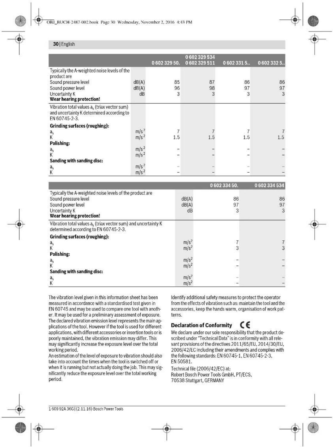
Sound emission values determined according to EN 60745-2-3.
| 0 602 301 40. | 0 602 301 434 | 0 602 304 40. | 0 602 305 40. | |
| Typically the A-weighted noise levels of the product are | ||||
| Sound pressure level | dB(A) | 72 | 82 | 79 |
| Sound power level | dB(A) | 83 | 93 | 90 |
| Uncertainty K | dB | 3 | 3 | 3 |
| Wear hearing protection! | ||||
| Vibration total values \( a_{\mathrm {n}} \)(triax vector sum) and uncertainty K determined according to EN 60745-2-3. | ||||
| Grinding surfaces (roughing): | ||||
| \( a_{\mathrm {n}} \) | m/s2 | - | 5.3 | 5 |
| K | m/s2 | - | 2 | 2 |
| Polishing: | ||||
| \( a_{\mathrm {n}} \) | m/s2 | 3 | 3 | - |
| K | m/s2 | 1.5 | 1.5 | - |
| Sanding with sanding disc: | ||||
| \( a_{\mathrm {n}} \) | m/s2 | 3 | 3 | - |
| K | m/s2 | 1.5 | 1.5 | - |
| 0 602 306 434 | 0 602 324 40. | 0 602 324 44,0 602 324 4640 602 324 4740 602 324 434 | |
| Typically the A-weighted noise levels of the product are | |||
| Sound pressure level dB(A) | 82 | 77 | 82 |
| Sound power level dB(A) | 93 | 88 | 93 |
| Uncertainty K dB | 3 | 3 | 3 |
| Wear hearing protection! | |||
| Vibration total values \( a_h \) (triax vector sum) and un-certainty K determined according to EN 60745-2-3. | |||
| Grinding surfaces (roughing): | |||
| \( a_h \)m/s2 | - | - | 6 |
| Km/s2 | - | - | 2 |
| Polishing: | |||
| \( a_h \)m/s2 | < 2.5 | 4 | - |
| Km/s2 | 1.5 | 1.5 | - |
| Sanding with sanding disc: | |||
| \( a_h \)m/s2 | < 2.5 | 4 | - |
| Km/s2 | 1.5 | 1.5 | - |

Henk Becker
Executive Vice President Engineering
Heimut Heinzelmann
Head of Product Certification PT/ECS
Robert Bosch Power Tools GmbH
70538 Stuttgart, GERMANY
Stuttgart, 01.01.2017
Assembly
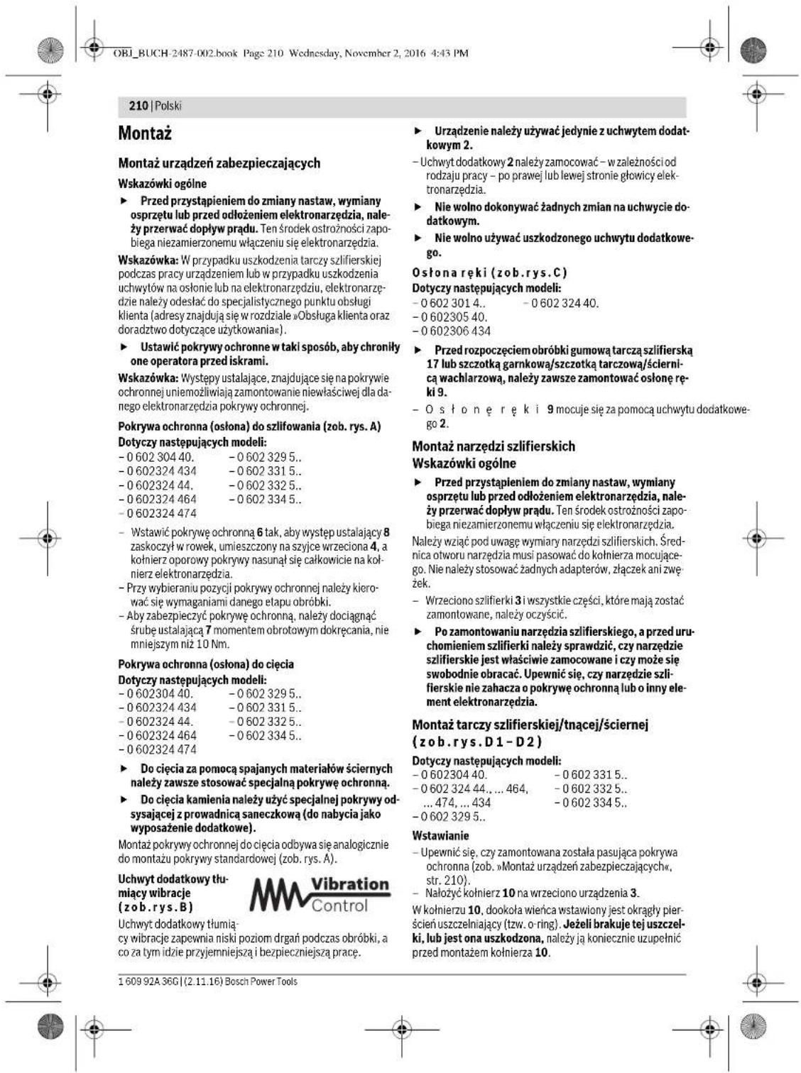
Mounting the Protective Devices
General Information
- Disconnect the power supply before making any adjustments, changing accessories, or placing the machine aside. This safety measure prevents accidental starting of the power tool.
Note: After breakage of the grinding disc during operation or damage to the holding fixtures on the protection guard/power tool, the machine must promptly be sent to an after-sales service agent for maintenance. For addresses, see section "After-sales Service and Application Service".
Adjust protection guards in such a manner that sparking toward the operator is prevented.
Note: The encoding keys of the protection guards ensure that only a protection guard that fits the machine type can be mounted.
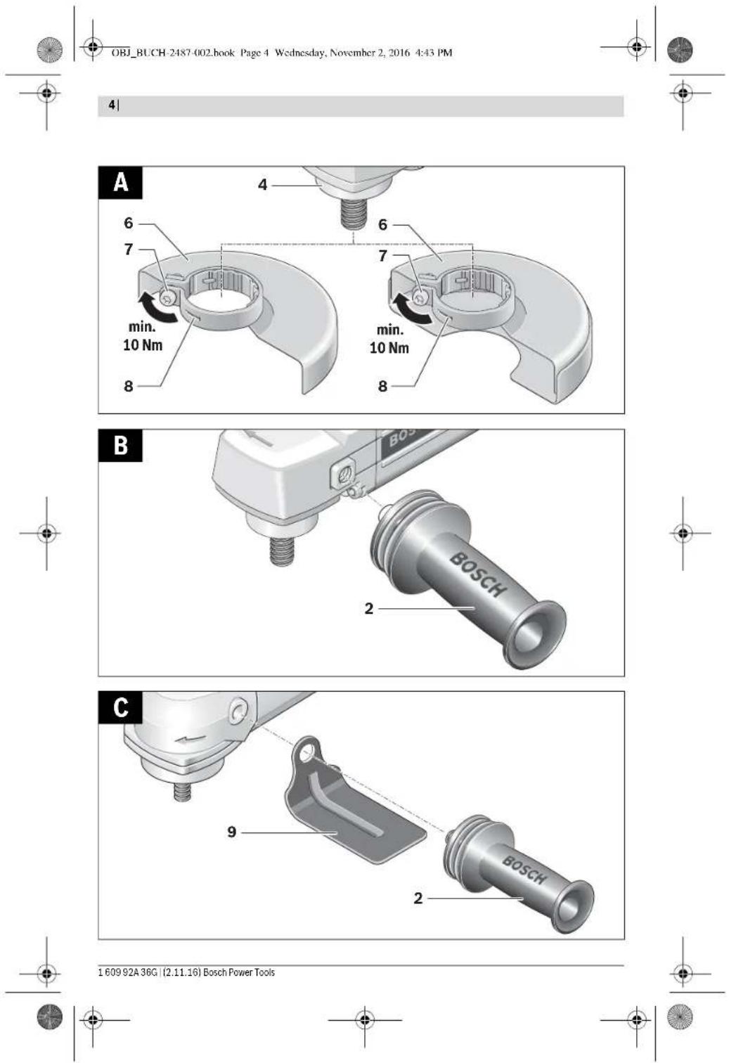
Protection Guard for Grinding (see figure A)
Applies for the following types:
-060230440. -06023295.. -0602324434 -06023315.. -060232444. -06023325.. -0602324464 -06023345. -0602324474
- Place the protection guard 6 with the encoding key 8 engaging into the groove on the spindle collar 4 until the shoulder of the protection guard is seated against the flange of the power tool.
- Adapt the position of the protection guard to the requirements of the work step.
- Secure the protection guard by tightening locking screw 7 with a tightening torque of at least 10Nm
Protection Guard for Cutting
Applies to the following types:
-060230440. -06023295.. -0602324434 -06023315.. -060232444. -06023325.. -0602324464 -06023345.. -0602324474
For cutting with bonded abrasives, always use a protection guard for cutting. For cutting stone, always use a cutting guide with dust extraction protection guard (accessory).
The protection guards for cutting are mounted analogously to the standard protection guards (see figure A).
Vibration-dampening
Auxiliary Handle
(see figure B)
The vibration-dampening auxiliary handle reduces vibrations, making operation more comfortable and secure.
Operate your machine only with the auxiliary handle 2. Screw the auxiliary handle 2 on the right or left of the machine head depending on the working method. Do not make any alterations to the auxiliary handle. Do not continue to use an auxiliary handle if it is damaged.
Hand Guard (see figure C)
Applies to the following types: -06023014.. -060232440. -060230540. -0602306434
For operations with the rubber sanding plate 17 or with the cup brush/wheel brush/flap disc, always mount the hand guard 9. The hand guard 9 is fastened with the auxiliary handle 2.
Mounting the Grinding Tools
General Information
Disconnect the power supply before making any adjustments, changing accessories, or placing the machine aside. This safety measure prevents accidental starting of the power tool.
Pay attention to the dimensions of the grinding tools. The mounting hole diameter must fit the mounting flange without play. Do not use reducers or adapters.
Clean the grinder spindle 3 and all parts to be mounted.
After mounting the grinding tool and before switching on, check that the grinding tool is correctly mounted and that it can turn freely. Make sure that the grinding tool does not graze against the protection guard or other parts.
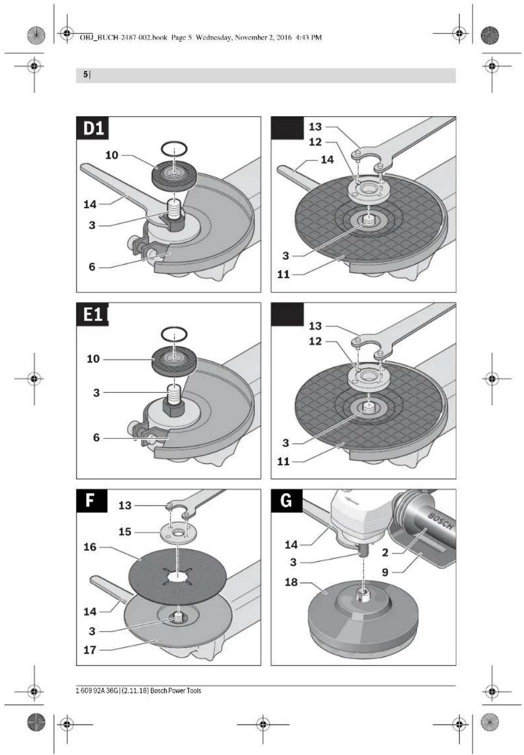
Mounting Grinding or Cutting Discs (see figures D1-D2)
Applies for the following types:
-060230440. -06023315.. -060232444,..464 -06023325. 474.434 -06023345
-06023295..
Installation
- Make sure that the fitting protection guard is mounted (see "Mounting the Protective Devices", page 31).
- Place the clamping flange 10 on the grinder spindle 3. A plastic part (O ring) is fitted around the centring collar of mounting flange 10. If the O-ring is missing or damaged, it must immediately be replaced before mounting flange 10 is mounted.
- Mount the desired grinding/cutting disc 11 in the correct rotation direction onto the grinder spindle 3.


- Place the clamping nut 12 onto the spindle thread so that the central recess of the clamping nut faces upward. Tighten the clamping nut with two-pin spanner 13, while counter-holding the spanner surfaces of the grinder spindle 3 with open-end spanner 14.
Removal
Hold the grinder spindle 3 on the spanner surfaces with open-end spanner 14. - Unscrew the clamping nut 12 from the grinder spindle with two-pin spanner 13, while counter-holding the spanner surfaces with open-end spanner 14. - Afterwards, pull the grinding tool and the mounting flange from the grinder spindle.
Machines with Spindle Lock Button 5
Applies for the following types:
-060232440. -0602324434 -060232444.
For machines with spindle lock button 5, counter-holding with an open-end spanner is not required when mounting grinding tools (see figures E1-E2).
- Actuate the spindle lock button only when the grinder spindle is at a standstill. Otherwise, the machine may become damaged.
- Before installing or removing the grinding tool, press and hold spindle lock button 5 to lock the grinder spindle 3 in place.
- Mount the desired grinding tool (see "Mounting Grinding or Cutting Discs", page 31).
- Let go of the spindle lock button 5 to release the locked grinder spindle.
Mounting the Rubber Sanding Plate (see figure F)
Applies for the following types:
-06023014. -060232440 -060230540. -0602306434
Installation
- Make sure that the hand guard and the auxiliary handle are mounted (see "Mounting the Protective Devices", page 31).
- Place the rubber sanding plate 17 onto the grinder spindle 3. Lay the sanding disc 16 on the rubber sanding plate.
- Place the round nut 15 on the spindle collar.
- Tighten the round nut with two-pin spanner 13, while counter-holding the spanner surfaces of the grinder spindle 3 with open-end spanner 14. Take care that the round nut 15 is screwed completely into the bulge of the rubber sanding plate so that it does not interfere while sanding and the sanding disc is firmly seated.
Removal
Hold the grinder spindle 3 on the spanner surfaces with open-end spanner 14.
- Unscrew the round nut 15 from the grinder spindle with two-pin spanner 13, while counter-holding the spanner surfaces with open-end spanner 14.
- Pull the sanding disc and the rubber sanding plate from the grinder spindle.
Mounting the Buffing Disc (see figure G)
Applies for the following types:
Pay attention that the thread of the buffing disc fits exactly on the grinder spindle thread (M14).
Make sure that the hand guard and the auxiliary handle are mounted (see "Mounting the Protective Devices", page 31). Screw the buffing disc 18 so far onto the grinder spindle 3 that it rests firmly against the face surface of the grinder spindle, while counter-holding the spanner surfaces of the grinder spindle 3 with open-end spanner 14.
Removal
Unscrew the tightly seated buffing disc 18 from the grinder spindle by applying an open-end spanner to the buffing disc spanner surfaces, while counter-holding the spanner surfaces of the grinder spindle 3 with open-end spanner 14.
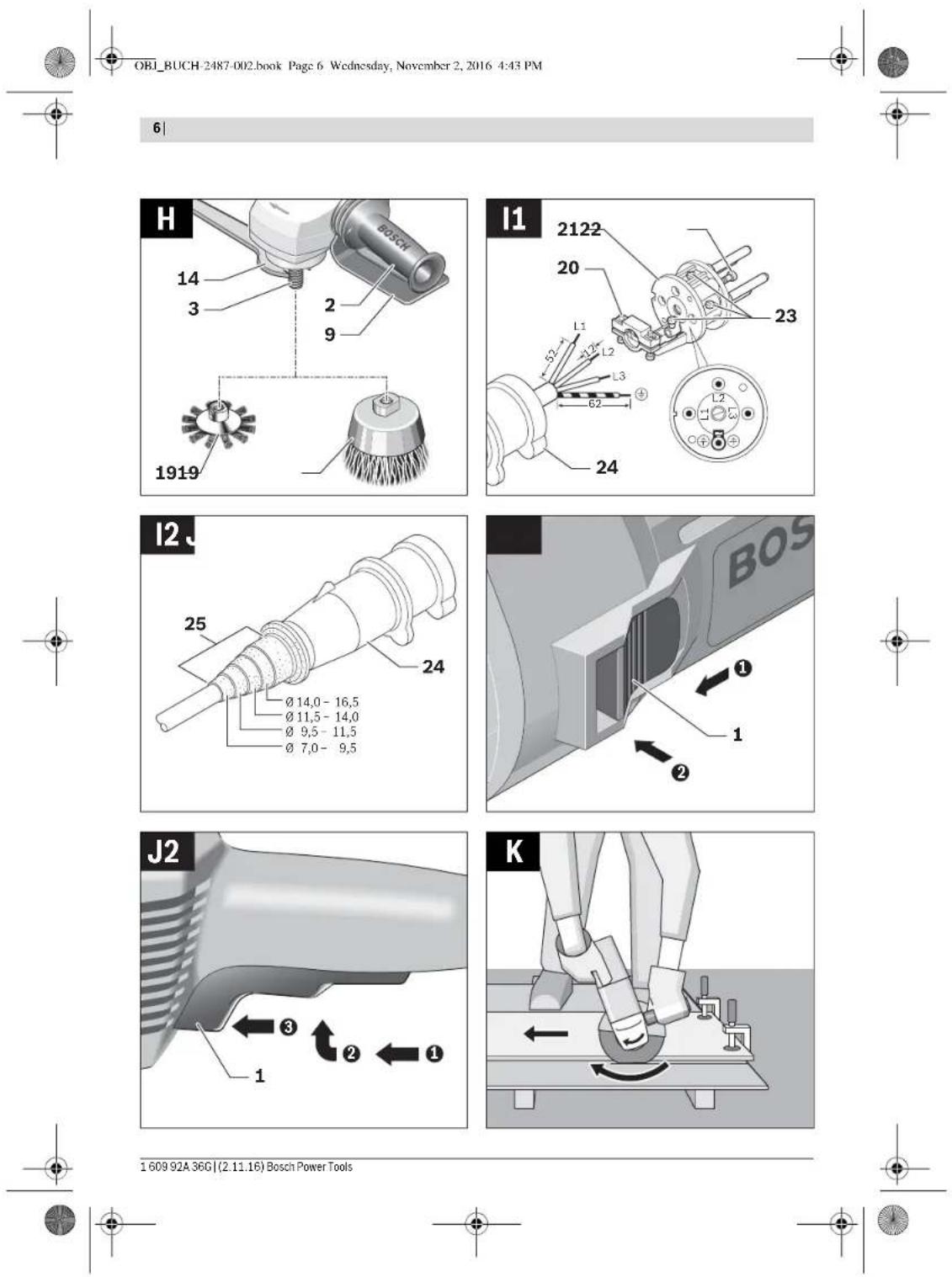
Mounting Wire Brushes (see figure H)
Applies for the following types:
-060230440. -06023315.. -060232444,..464, -06023325. 474.434 -06023345..
-06023295..
Installation
Pay attention that the thread of the wire brush fits exactly on the grinder spindle thread (M14).
Make sure that the hand guard and the auxiliary handle are mounted (see "Mounting the Protective Devices", page 31). Screw the desired wire brush 19 (cup brush or wire wheel) so far onto the grinder spindle 3 that it rests firmly against the face surface of the grinder spindle, while counter-holding the spanner surfaces of the grinder spindle with open-end spanner 14.
Removal
- Unscrew the tightly seated wire brush 19 from the grinder spindle by applying an open-end spanner to wire brush spanner surfaces, while counter-holding the spanner surfaces of the grinder spindle 3 with open-end spanner 14.
Dust/Chip Extraction
Dusts from materials such as lead-containing coatings, some wood types, minerals and metal can be harmful to one's health. Touching or breathing-in the dusts can cause allergic reactions and/or lead to respiratory infections of the user or bystanders.

Certain dusts, such as oak or beech dust, are considered as carcinogenic, especially in connection with wood-treatment additives (chromate, wood preservative). Materials containing asbestos may only be worked by specialists.
- As far as possible, use a dust extraction system suitable for the material.
- Provide for good ventilation of the working place.
- It is recommended to wear a P2 filter-class respirator. Observe the relevant regulations in your country for the materials to be worked.
Prevent dust accumulation at the workplace. Dusts can easily ignite.
Connection to the Power Supply
For operation of the power tools, a frequency converter is required that generates three-phase current with a frequency according to that listed on the type plate.
Frequency converters are available in various sizes, with different frequencies, secondary voltages and rated outputs. The choice of the frequency converter depends on the power tools to be connected. When selecting a frequency converter, contact your Bosch-specialist shop for advice.
The machine is provided with a four meter long specialty cable without plug. To put it into operation, the specialty cable must be equipped with a four-pole CEE plug (identification colour green).
Additionally, the machine can be equipped with a commercially available motor protection switch for protection against overload. The adjustment range of the motor protection switch must cover the nominal current of the power tool (see "Technical Data"). The motor protection switch must react in less than one second.
Please observe the safety warnings and assembly instructions in the operating instructions of the motor protection switch!
Mounting the CEE Plug (see figures 11-12)
- Loosen the two screws 22 and pull the plug insert 21 out of the plug housing of the CEE plug 24. Cut off the plastic sleeve 25 according to the diameter of the specialty cable of the power tool and insert the specialty cable through the CEE plug housing.
- Insert the four conductors through the cable strain relief 20.
- Loosen the four small screws 23 in the plug insert 21 and insert
the conductor ferrule of the brown L1 conductor into contact tube L1.
the conductor ferrule of the blue L2 conductor into contact tube L2;
the conductor ferrule of the black L.3 conductor into contact tube L3,
and the conductor ferrule of the green/yellow conductor into the earthing contact tube.
- Firmly tighten the four small screws 23 in the plug insert 21 to affix the conductors.
- Now, tighten the screws of the cable strain relief 20 so that the cable clamp goes around the complete cable sheath, ensuring that no pressure is on the conductor ferrules.
- Reinsert plug insert 21 into the housing of the CEE plug 24 and tighten both screws 22 again.
- Afterwards, check the proper function of the protective conductor.
- Insert the CEE plug 24 of the power tool into the connection socket of the frequency converter.
Now, connect the frequency converter to the power supply. For information on how to connect the frequency converter to the power supply, see the frequency converter operating instructions. Afterwards, check the rotation direction!
Checking the Rotation Direction
The rotation direction of the grinder spindle must correspond with the arrow on the power tool. If the grinder spindle rotates in the wrong direction when putting into operation for the first time (see "Switching the Power Tool On/Off", page 34), switch the power tool off immediately and disconnect it from the power supply. - Loosen the two screws 22 again and pull the plug insert 21 out of the plug housing of the CEE plug 24. - Loosen the conductor ferrules of the black and brown conductors from their contact tubes. - Now, insert the conductor ferrule of the black conductor L3 into contact tube L1, and the conductor ferrule of the brown conductor L1 into contact tube L3. - Firmly tighten the small screws 23 in the plug insert 21 to affix the conductors. - Reinsert plug insert 21 into the housing of the CEE plug 24 and tighten both screws 22 again. - Afterwards, check the proper function of the protective conductor. - Reconnect the power tool to the power supply.
Operation
Starting Operation
The voltage and frequency of the power source must correspond with the data on the type plate of the power tool. - Check grinding tools before using. The grinding tool must be mounted properly and be able to move freely. Carry out a test run for at least one minute with no load. Do not use damaged, out-of-centre or vibrating grinding tools. Damaged grinding tools can burst and cause injuries. If the machine should unexpectedly stop operating even though the On/Off switch 1 is in the "On" position, set the On/Off switch to "Off". This will prevent uncontrolled restarting of the machine. Before restarting the machine, check the power supply (see "Connection to the Power Supply", page 33). Always connect the power tool to the frequency converter first, before connecting the frequency converter to the mains supply.
To save energy, only switch the power tool on when using it.




Switching the Frequency Converter On/Off
The frequency converter must be put into operation first before actuating the power tool.
For this, observe the operating instructions of the frequency converter.
Switching the Power Tool On/Off with the On/Off Switch (see figure J1)
Applies for the following types:
-06023244.
- To start the machine, push the On/Off switch 1 forwards.
- To lock the On/Off switch 1, press the On/Off switch 1 down at the front until it latches. To switch off the power tool, release the On/Off switch 1. When the On/Off switch 1 is locked-on, briefly press it toward the rear and then release it.
Switching the Power Tool On/Off
with Safety Switch (see figure J2)
Applies for the following types:
-06023014. -06023295. -060230440. -06023315. -060230540-06023325 -0602306434 -06023345
- To start the power tool, press the On/Off switch 1 forward and then down.
- To lock on the pressed On/Off switch 1, push the On/Off switch 1 further forward.
- To switch off the power tool, release the On/Off switch 1. Or when it is locked, briefly press the On/Off switch 1 and then release it.
Working Advice
- Disconnect the power supply before making any adjustments, changing accessories, or placing the machine aside. This safety measure prevents accidental starting of the power tool. Exercise caution when cutting slots in structural walls; see Section "Information on Structures".
- Clamp the workpiece if it does not remain stationary due to its own weight. Do not strain the machine so heavily that it comes to a standstill. After heavily straining the power tool, continue to run it at no-load for several minutes to cool down the accessory.
Sanding with the Flap Disc
With the flap disc (accessory), curved surfaces and profiles can be worked.
Flap discs have a considerably higher service life, lower noise levels and lower sanding temperatures than conventional sanding sheets.
Cutting Metal (see figure K)
For cutting with bonded abrasives, always use a protection guard for cutting.
When cutting, work with moderate feed, adapted to the material being cut. Do not exert pressure onto the cutting disc, tilt or oscillate the machine.
Do not reduce the speed of running down cutting discs by applying sideward pressure. The machine must always work in an up-grinding motion. Otherwise, the danger exists of it being pushed uncontrolled out of the cut. When cutting profiles and square bar, it is best to start at the smallest cross section.
Cutting Stone
- Provide for sufficient dust extraction when cutting stone. Wear a dust respirator. The machine may be used only for dry cutting/grinding.
For cutting stone, it is best to use a diamond cutting disc. For safety against jamming, a special cutting guide with dust extraction protection guard (accessory) must be used. Operate the machine only with dust extraction and additionally wear a dust protection mask. The vacuum cleaner must be approved for the extraction of masonry dust. Bosch provides suitable vacuum cleaners. - Switch on the machine and place the front part of the cutting guide on the workpiece. Slide the machine with moderate feed, adapted to the material to be worked. For cutting especially hard material, e.g., concrete with high pebble content, the diamond cutting disc can overheat and become damaged as a result. This is clearly indicated by circular sparking, rotating with the diamond cutting disc. In this case, interrupt the cutting process and allow the diamond cutting disc to cool by running the machine for a short time at maximum speed with no load. Noticeably decreasing work progress and circular sparking are indications of a diamond cutting disc that has become dull. Briefly cutting into abrasive material (e.g., lime-sand brick) can reshappen the disc again.
Information on Structures
Slots in structural walls are subject to the Standard DIN 1053 Part 1, or country-specific regulations. These regulations are to be observed under all circumstances. Before beginning work, consult the responsible structural engineer, architect or the construction supervisor.
Rough Grinding
Never use a cutting disc for roughing.
The best roughing results are achieved when setting the machine at an angle of 30° to 40° . Move the machine back and forth with moderate pressure. In this manner, the workpiece will not become too hot, does not discolour and no grooves are formed.
Sanding with Sanding Discs and the Rubber Sanding Plate
The choice of the suitable sanding paper depends on the material to be worked.
Bosch offers various sanding-paper qualities that fit the rubber sanding plate. Contact your specialist shop for advice.
Executive Vice President
Engineering
Helmut Heinzelmann
Head of Product Certification
PT/ECS
iV. h = mc
Robert Bosch Power Tools GmbH
70538 Stuttgart, GERMANY
Stuttgart, 01.01.2017
Assembly
Henk Becker Helmut Heinzelmann Executive Vice President Head of Product Certification Engineering PT/ECS

Robert Bosch Power Tools GmbH
70538 Stuttgart, GERMANY
Stuttgart, 01.01.2017
Assembly
62 | Spanish
Slide the protective cap over the flange of the power tool.
Spanish | 65
-06023014.. -06023295.. -060230440. -06023315.. -060230540. -06023325.. -0602306434 -06023345..
Portuguese 75
Portuguese 77
Executive Vice President
Engineering
Helmut Heinzelmann
Head of Product Certification
PT/ECS

Robert Bosch Power Tools GmbH
70538 Stuttgart, GERMANY
Stuttgart, 01.01.2017
Assembly
arms reduce vibrations
OBI_BUCH-2487-002.book Page:91 Wednesday, November 2, 2016 4:43 PM
Italian | 91
OBI_BUCH-2487-002.book Page:93 Wednesday, November 2, 2016 4:43 PM
Executive Vice President
Engineering
Helmut Heinzelmann
Head of Product Certification
PT/ECS
i.v. k = m _____
Robert Bosch Power Tools GmbH
70538 Stuttgart, GERMANY
Stuttgart, 01.01.2017
Bosch Power Tools 1609 92A 36C (2.11.16)


94 Italian
Assembly
OBI_BUCH-2487-002.book Page 104 Wednesday, November 2, 2016 4:43 PM
104 Dutch
OBI_BUCH-2487-002.book Page 107 Wednesday, November 2, 2016 4:43 PM
Dutch | 107
OBI_BUCH-2487-002.book Page 109 Wednesday, November 2, 2016 4:43 PM
Dutch | 109
Henk Becker Helmut Heinzelmann Executive Vice President Head of Product Certification Engineering PT/ECS

Robert Bosch Power Tools GmbH 70538 Stuttgart, GERMANY Stuttgart, 01.01.2017
Assembly
110|Nedenlads
Dansk|123
| 0 602 329 50. | 0 602 329 534 | 0 602 331 5.. | 0 602 332 5.. | ||
| 0 602 329 511 | |||||
| Samléde vibrationsværddier \( a_h \) (vektorsumfor tre retninger) og usikkerhed K beregnetiht. EN 60745-2-3. | |||||
| Overfladeslibning (skrubning): | |||||
| \( a_h \) | \( m/s^2 \) | 7 | 7 | 7 | 7 |
| K | \( m/s^2 \) | 1,5 | 1,5 | 1,5 | 1,5 |
| Polering: | |||||
| \( a_h \) | \( m/s^2 \) | - | - | - | - |
| K | \( m/s^2 \) | - | - | - | - |
| Slibning med silbeblad: | |||||
| \( a_h \) | \( m/s^2 \) | - | - | - | - |
| K | \( m/s^2 \) | - | - | - | - |
| 0 602 334 50. | 0 602 334 534 | |
| Værktajets A-vurdere lydtrykniveau er typisk | ||
| Lydtrykniveau | dB(A) | 86 |
| Lydeffektniveau | dB(A) | 97 |
| Usikkerhed K | dB | 3 |
| Brug horevaarn! | ||
| Samlke vibrationsværddier \( a_{i} \) (vektorsum for tre retninger) ogusikkerhed K beregnet iht. EN 60745-2-3. | ||
| Overfladeslibning (skrubning): | ||
| \( a_{i} \) | \( m/s^2 \) | 7 |
| K | \( m/s^2 \) | 3 |
| Polering: | ||
| \( a_{i} \) | \( m/s^2 \) | - |
| K | \( m/s^2 \) | - |
| Slibning med silbeblad: | ||
| \( a_{i} \) | \( m/s^2 \) | - |
| K | \( m/s^2 \) | - |
Executive Vice President
Engineering
Helmut Heinzelmann
Head of Product Certification
PT/ECS

Robert Bosch Power Tools GmbH
70538 Stuttgart, GERMANY E-mail: j.1942@hazette.de
Stuttgart, 01.01.2017
Assembly
132 | Swedish
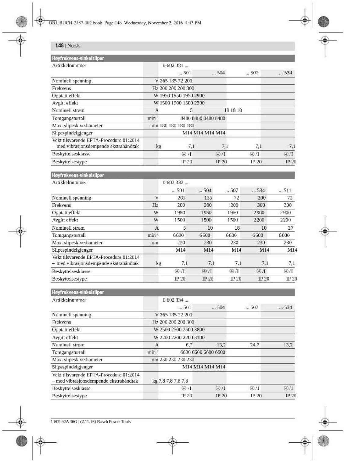
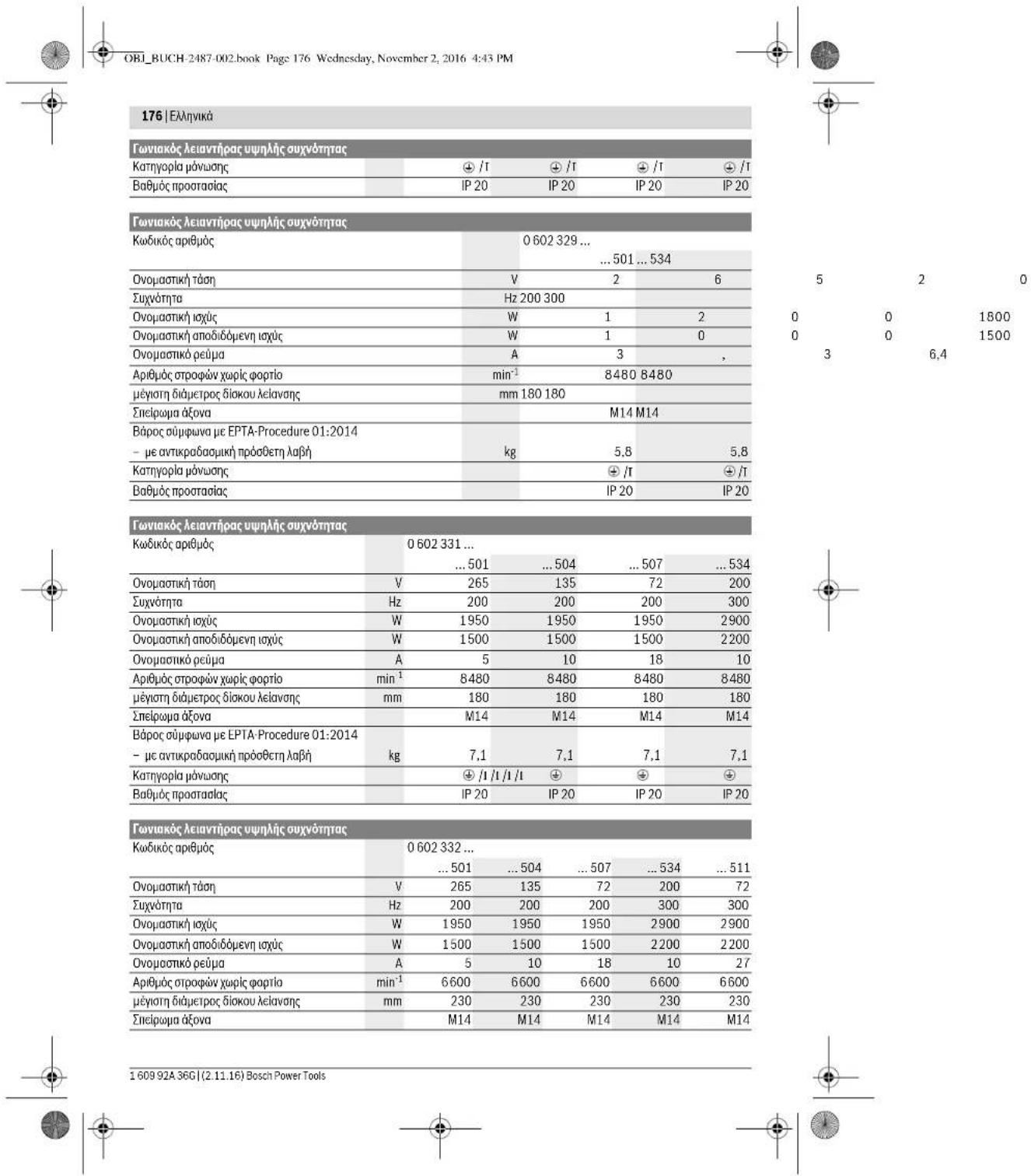
| Högtfrekvensvinkelslipar | ||||||
| Märkström A | 5 | 10 18 10 27 | ||||
| Tomgängsvartval | min1 | 6600 | 6600 | 6600 | 6600 | |
| max. slipskivsdiameter | mm 230 | 230 | 230 | 230 | ||
| Slipspindelgånga | M14 | M14 | M14 | M14 | ||
| Vikt enlig EPTA-Procedure 01:2014 - med vibrationsdämpande stöchhandtag | kg | 7,1 | 7,1 | 7,1 | 7,1 | 7,1 |
| Skyddsklass | ± /I | ± /I | ± /I | ± /I | ± /I | |
| Kapslingsklass | IP 20 | IP 20 | IP 20 | IP 20 | IP 20 | |
| Högfrektvensvinkelslipar | |||||
| Artikelnummer | 0 602 334 ... | ||||
| ... 501 | ... 504 | ... 507 | ... 534 | ||
| Märksprüning | V | 265 | 135 | 72 | 200 |
| Frekvens | Hz | 200 | 200 | 200 | 300 |
| Upptagen märkeffekt | W | 2500 | 2500 | 2500 | 3800 |
| Avgiven märkeffekt | W | 2200 | 2200 | 2200 | 3100 |
| Märkström | A | 6,7 | 13,2 | 24,7 | 13,2 |
| Tomgangsvarval | min1 | 6600 | 6600 | 6600 | 6600 |
| max. slipskivsdiameter | mm | 230 | 230 | 230 | 230 |
| Slippspindelgänga | M14 | M14 | M14 | M14 | |
| Vikt enligt EPTA-Procedure 01:2014 - med vibrationsdämpande stödhandtag | kg | 7,8 | 7,8 | 7,8 | 7,8 |
| Skyddsklass | #/1 | #/1 | #/1 | #/1 | |
| Kapslingsklass | IP 20 | IP 20 | IP 20 | IP 20 | |

Henk Becker Executive Vice President Engineering
Helmut Heinzelmann Head of Product Certification PT/ECS

Robert Bosch Power Tools GmbH 70538 Stuttgart, GERMANY Stuttgart, 01.01.2017
Assembly
138 | Swedish
Vibration-damping auxiliary handle (see figure B)
140 | Swedish
Bosch Service Center
Telegrafvej 3
2750 Ballerup
Denmark
Tel.: (08) 7501820 (within Sweden)
Fax: (011) 187691
Waste disposal
Applies to all types



Norwegian | 149
Subject to change without notice.
Finnish
Safety instructions
Finnish | 159
162 | Finnish
| 0602 301 40. | 0602 301 434 | 0602 304 40. | 0602 305 40. | |
| Värähtely nhteisarvot a, (kolmen suunnan vektorisumma) ja epävarnuus K mitattuna EN 60745-2-3 mukaan. | ||||
| Pintahionta (karhennus): | ||||
| a, | m/s2 | - | 5,3 | 5 |
| K | m/s2 | - | 2 | 2 |
| Kiillotus: | ||||
| a, | m/s2 | 3 | 3 | - |
| K | m/s2 | 1,5 | 1,5 | - |
| Honta hiomapaperilla: | ||||
| a, | m/s2 | 3 | 3 | - |
| K | m/s2 | 1,5 | 1,5 | - |
Henk Becker Executive Vice President Engineering
Helmut Heinzelmann Head of Product Certification PT/ECS
Installation
-060230440. -06023295.. -0602324434 -06023315.. -060232444. -06023325.. -0602324464 -06023345.. -0602324474
Instructions for the installer:
Product description and power

This electric tool is intended for both professional and household use, as well as for use in accordance with the instructions for all electric tools and power tools.
We ask that you open the package with the tool's documentation and read the instructions carefully before using the tool.
Intended use
Suitable for the following types
-06023014 -0.60230540 -0.602306434 -0.60232440
The electric tool is intended for cutting and grinding, as well as for polishing and sanding without the use of water.
Suitable for the following types
-0.60230440 -060232444...464...474...434 -06023295. -06023315 -06023325 -06023345.
The electric tool is designed for cutting and grinding, and it has been tested and approved for use with the appropriate accessories.
For cutting with abrasive materials, it is necessary to use a suitable protective guard.
For cutting with diamond blades, it is necessary to provide for sufficient cooling of the blade.
Power tool types
It is permitted to use accessories that are not supplied or recommended by the manufacturer with this electric tool, provided they are suitable for the intended use.
Illustrated components
The numbering of the illustrated components refers to the illustration of the electric tool on the graphics page.
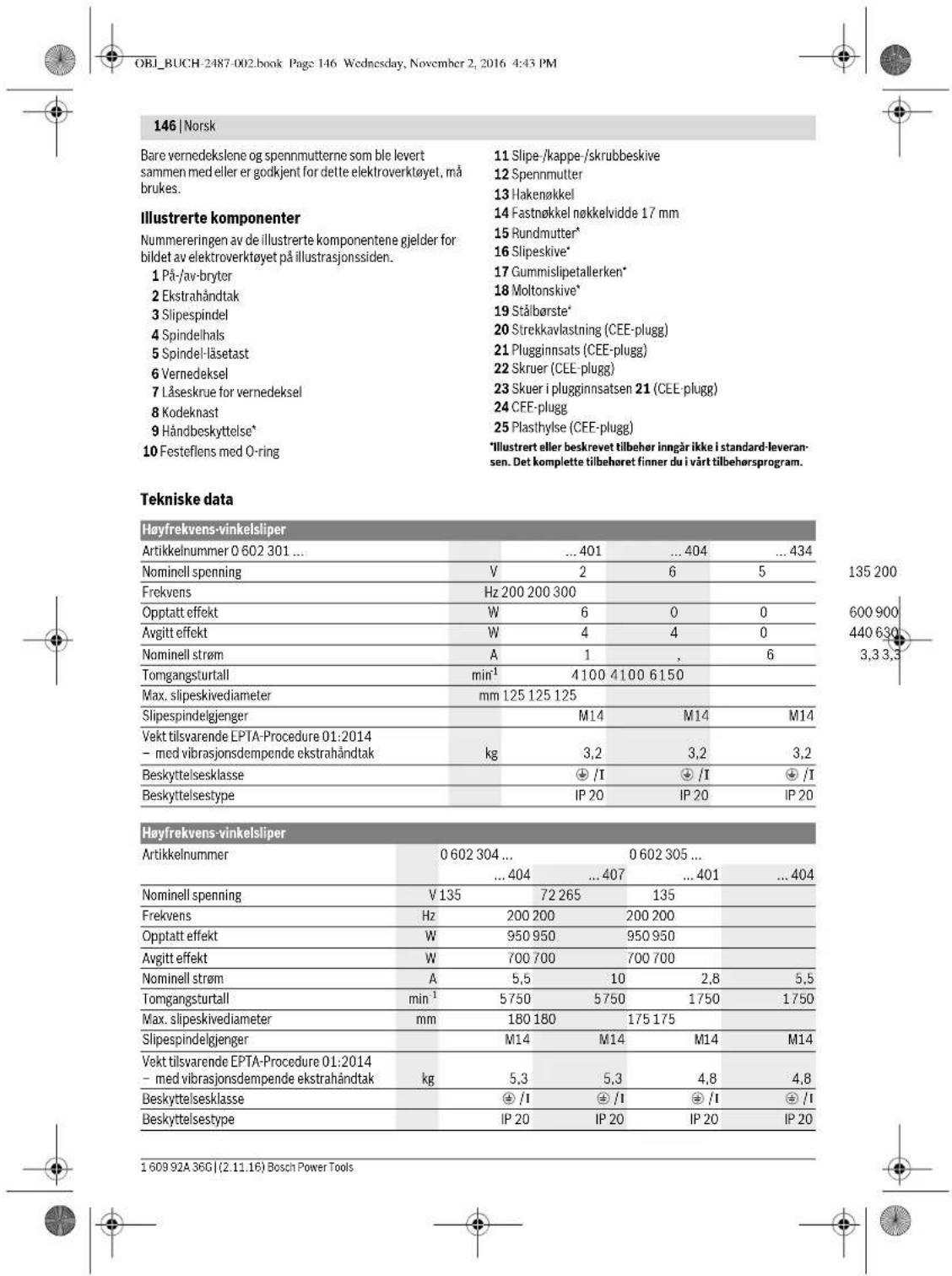
1AakotIncON/OFF 2PooeemAaBn 3Aovor 4Aaipoc dOova 5PiKpOaVbAOWcEova 6Pooqukntpac 7 Bla6 oTepeoong ia npopuλaKTHpa 8Kwokonoinpevoekkvto 9Ppuaakmpacxepio
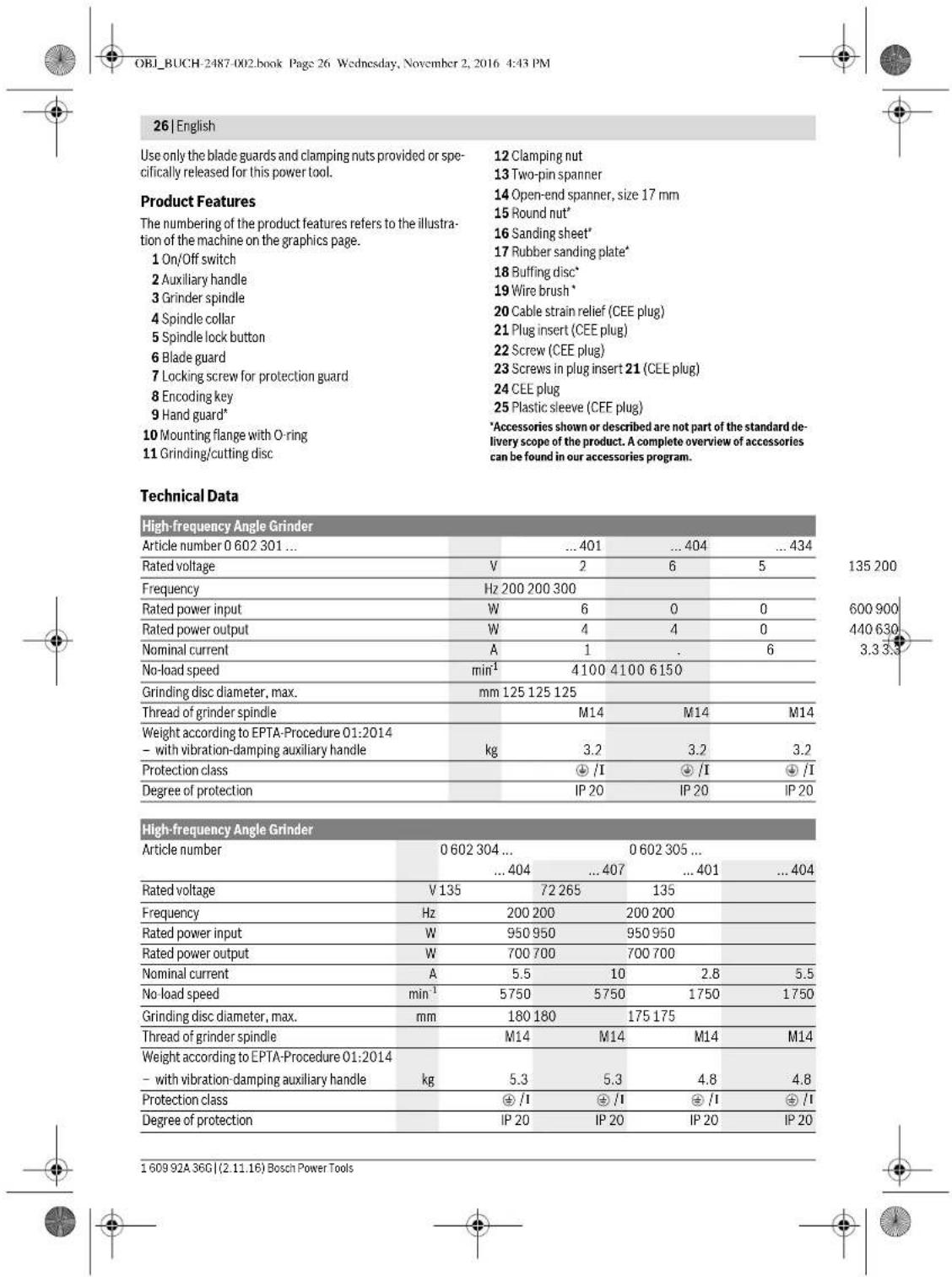
10ΦλavntzunodoxhμεδakruiioO 11AioKcIeIavang/ konh/c/ekovdpapatoc 12NaIgduoqapng 13TayocAic 14FepavikKaei6ipeovypa 17mm 15 TpoWuAoEa 16ΦAaλeaygnc 17 EAaOIOKc bIOKc AEiavong 18diokocoiAwoonC 19∑μρατόβομτα 20 Avakoupiqan katanovnnc (pc CFE) 21Eepnua pic (pCCEE) 22 Bièç (φις CEE) 23 Biéçσo éçaptnμa φις 21 (φις CEE) 24ΦCEB 25 Paaonik npoopa (pCCEE) E'epoJtau no oneKoiovOvTuH npeyopovTai nepeixovTai ot tranotavpoueuaia. Tua nAnPn kataIoYo eApntmuTaw Koit aTo npoyapuaeApotpntuv.
Technical data
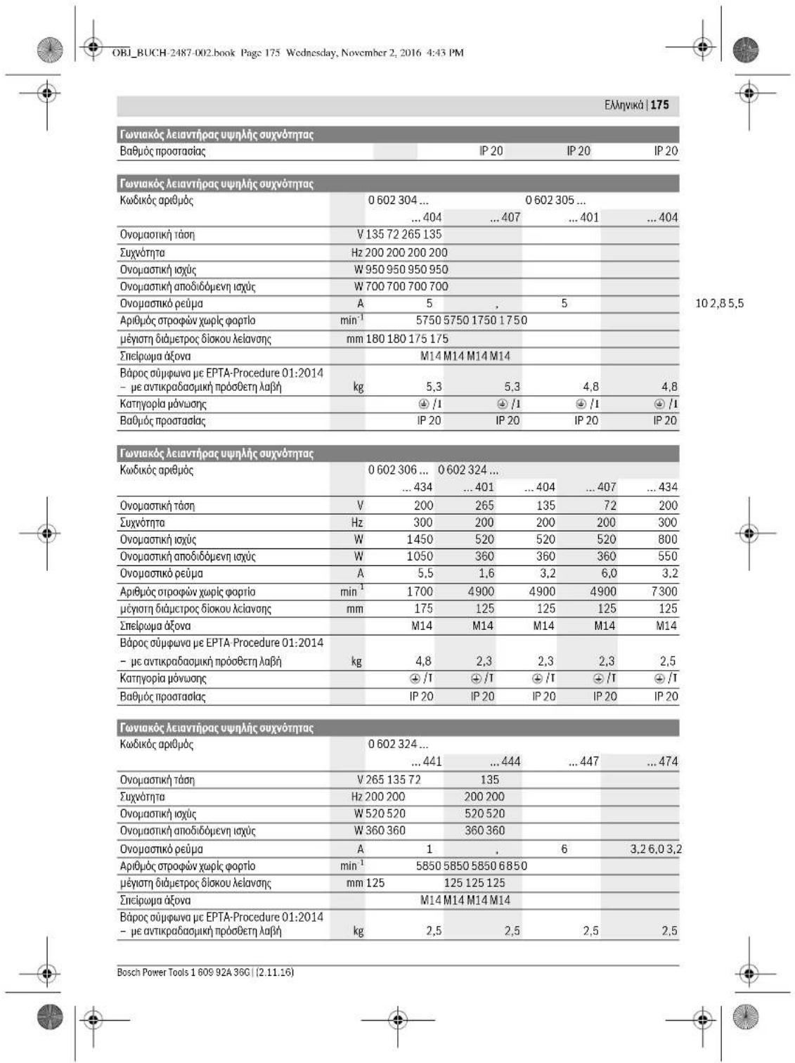
| Favivakóleiavtipac uunlncauvovmtac | ||||
| Kwδkóc apβμóc 0 602 301 ... | ...401 | ...404 | ...434 | |
| Övopaatikj táðn | V | 2 | 6 | 5 |
| Σuþvortna | Hz 200 200 300 | |||
| Övopaatikj iαúç | W | 6 | 0 | 0 |
| Övopaatikj anobidóevn iαúç | W | 4 | 4 | 0 |
| Övopaatikj pcūma | A | 1 | , | 6 |
| Apβμóc στροφών χαρίσ φορίσo | min¹ | 4100 | 4100 | 6150 |
| μεγοιŋ διαμετρος διοκου λελανασε | mm 125 125 125 | |||
| Σnelipoua áóva | M14 | M14 | M14 | |
| Bápoc ouμφωνa μe EPTA-Procedure 01:2014 | ||||
| - μe avικρaδaʊμkni pòóθcπ λαβñ | kg 3,2 3,2 3,2 | |||
| Katzyopia pòvuaŋç | ± /I | ± /I | ± /I | |
1609 92A 36G| (2.11.16) Bosch Power Tools


135200
600900
440630
3,33,3
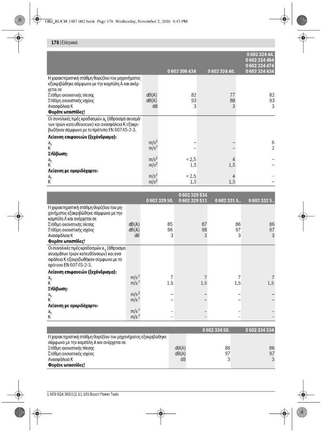
OBI_BUCH-2487-002.book Page 179 Wednesday, November 2, 2016 4:43 PM
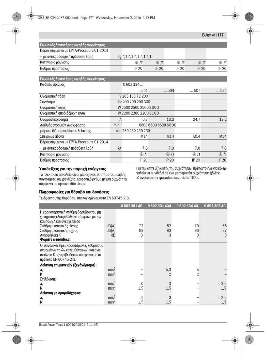
| 0602 334 50. | 0602 334 534 | |
| Ötouyolçük tüpec kpaşağmá yı, (şθροιασa ayucaŋaw trpov katcu-θυσεων) kai avaşpalaia K εξακρβωθηκαν σύμφωνa μe to npɔ:tuno EN 60745-2-3. | ||
| Aciavon emφavcew (ξεχόνδριαμα): | ||
| a1 | m/s2 | 7 |
| K | m/s2 | 3 |
| Σιλβωση: | ||
| a1 | m/s2 | - |
| K | m/s2 | - |
| Aciavon μe συμρίδαχρτο: | ||
| a1 | m/s2 | - |
| K | m/s2 | - |
The designation of the power tool refers to the type of tool. It is intended for use with the appropriate accessories. The designation is marked on the tool. The tool is designed for professional use. It is important to read and understand the safety instructions before use.
The designation of the power tool refers to the basic type of the power tool. Depending on the equipment, the power tool may be used for other purposes with different accessories. The designation is marked on the tool. This is intended to inform the user of the tool's intended use.
The designation of the power tool refers to the basic type of the power tool. The required safety instructions must be observed. The tool is designed for professional use. The designation is marked on the tool. This is intended to inform the user of the tool's intended use.
For this reason, the operation of the power tool must be carried out with the appropriate safety equipment. The power tool and its accessories must be used in accordance with the instructions. The operator must be trained in the use of the power tool.
Declaration of Conformity: We declare under our sole responsibility that the product described under “Technical data” is in conformity with the following directives: 2011/65/EU, 2014/30/EU, 2006/42/EC and the following standards: EN 60745-1, EN 60745-2-3, EN 50581. Technical file (2006/42/EC) at:
Robert Bosch Power Tools GmbH, PT/ECS, 70538 Stuttgart, GERMANY
Henk Becker Helmut Heinzelmann Executive Vice President Head of Product Certification Engineering PT/ECS
Robert Bosch Power Tools GmbH 70538 Stuttgart, GERMANY Stuttgart, 01.01.2017
Sigma
Safety instructions for power tools
General safety warnings
Read all safety warnings and all instructions. Failure to follow the warnings and instructions may result in electric shock, fire and/or serious injury. Save all warnings and instructions for future reference.
If the power tool is used in dusty conditions, the dust extraction system must be checked regularly and emptied. If the dust extraction system is blocked, the power tool must be taken to a Service center. For more information, see the chapter "Service and customer advice".
Keep the power tool away from rain or moisture. The entry of water into a power tool increases the risk of electric shock.
If the power tool is used in a damp location, it must be protected by a residual current device (RCD) to reduce the risk of electric shock.
Safety instructions for sanding (beta version A) apply to the following types:
-060230440. -06023295.. -0602324434 -06023315.. -060232444. -06023325.. -0602324464 -06023345.. -0602324474. Place the product on the sanding plate and secure it with the clamping lever.
180|Greek
Technical data for the product can be found in the operating instructions.
Lay it flat on the floor:
-06023014.. -060232440. -060230540. -0602306434
TonoBttn
-Remove the air filter cover by turning the two screws counterclockwise (see Figure 179). Turn the air filter cover counterclockwise and remove it. Turn the air filter element 16 to the left and remove it. Turn the fuel valve to the OFF position. Remove the air filter element by pulling it out with the tool 13, while pressing the clamp 14 on the air filter cover. 3. Remove the air filter element 15 from the air filter housing, so that it does not get dirty during operation and is protected from dust.
Removal
-Remove the air filter cover by turning the two screws 3 on the air filter cover counterclockwise. -Remove the air filter element 15 with the tool 13 from the air filter housing, while simultaneously pressing the clamp 14 on the air filter cover. -Remove the air filter element and the pre-filter from the air filter housing.
Function of the air filter (see figure G)
Important safety instructions:
OBI_BUCH-2487-002.book Page 183 Wednesday, November 2, 2016 4:43 PM
Greek183
Insert the power plug into the socket. Then turn the switch to the ON position.
Keep the power tool away from rain and moisture. This will prevent electric shock.
Switching on/off of the switch
Before you can turn the switch on, you must first plug in the power tool.
Please note the operating instructions for the switch.
For the automatic operation of the device, use the switch (see figure J1).
For the following types:
-06023244 - Via the remote control, the device is turned on/off by pressing the ON/OFF switch. To turn on the ON/OFF switch, press the ON/OFF switch again. The remote control is
With the remote control ON/OFF switch, press
the button towards the bottom and release it freely.
For the automatic operation of the device
with the switch (see figure J2)
For the following types:
-06023014.. -06023295.. -060230440. -06023315.. -060230540. -06023325.. -0602306434 -06023345..
To put the device into operation, press the ON/OFF switch towards the front and release it. To turn off the device, press the ON/OFF switch again. To put the device into operation, press the ON/OFF switch once more. If it is already on, press the switch once and then release it.
Maintenance
Disconnect the device from the power supply before cleaning or when replacing any parts. This prevents the risk of electric shock. If you notice any faults, contact the manufacturer. Keep the device away from children. Do not use the device if it is damaged or if the cord is damaged.
After cleaning the device, let it dry completely before using it again.
Operation with the remote control
With the remote control (included) you can operate the device and adjust the settings. The remote control has a larger range, better reception, and more functions than the device's own controls.
The chimney must be cleaned before use. The cleaning must be done with the chimney cold. Do not use the chimney if it is damaged or if the flue is blocked. Do not use the chimney with the flue blocked. The flue must be checked regularly for blockages. Risk of fire if the flue is blocked. If the flue is blocked, do not use the chimney.
Chimney cleaning
The chimney must be inspected regularly for proper operation. Wear protective gloves when cleaning. The inspection must be carried out only by a qualified specialist.
The chimney must be inspected for damage and blockages. To protect it from weather, the chimney must be inspected with a protective cover.
When working with the electric tool, always keep the ventilation openings of the chimney clear. The ventilation openings of the chimney must be kept clear. Bosch recommends suitable ventilation openings. Do not use the electric tool with the ventilation openings blocked. Keep the electric tool with the ventilation openings clear.
When using the chimney, e.g. with a wood-burning stove, it may overheat and cause a fire. A protective cover that is fitted with the chimney is part of the equipment.
In such a case, switch off the chimney and let it cool down for a while without any restrictions.
An important safety note: a defective flue and an unprofessional installation can cause damage.




To clean the chimney, you can remove it and clean it with a brush, e.g. with a chimney sweep.
Installation instructions
The wall brackets must be installed according to DIN 1053 Part 1 or the corresponding regulations of the country.
The installation must be carried out by a qualified person. Before starting work, consult the electrician, the architect or the builder.
The product note is described in the following text.
With a 30° to 40° angle, following the manufacturer's instructions, the results are achieved. Keep the power tool away from any flammable material. Thus, the workpiece is optimally secured, while avoiding any risk of fire.
The power tool is intended for cutting metal. The supplied cutting disc is suitable for this purpose, and it is used with the appropriate guard.
Bosch offers different types of cutting discs, specially designed for metal cutting. Ask your dealer for advice.
192|Turkish
| Yüksek frekanslı taşlama makinesi | |||||
| Ürün kodu | 0 602 334 ... | ||||
| ... 501 | ... 504 | ... 507 | ... 534 | ||
| Anma gerilimi | V 265 135 72 200 | ||||
| Frekans | Hz 200 200 200 300 | ||||
| Girgis Güçü | W 2500 2500 2500 3800 | ||||
| Çkış Güçü | W 2200 2200 2200 3100 | ||||
| Anma akimi | A 6 | . | 7 | 13,2 24,7 13,2 | |
| Bostaki devir saysi | dev/dak 6600 6600 6600 6600 | ||||
| Maks., taşlama disiki capi | mm 230 230 230 230 | ||||
| Taşlama mili disi | M14 M14 M14 M14 | ||||
| Aşırkı EPTA-Procedure 01:2014'e gore - Titresim onleyici ek tutamakla | kg 7,8 | 7,8 | 7,8 | 7,8 | |
| Koruma sinifi | + / I | + / I | + / I | + / I | |
| Koruma Türü | IP 20 | IP 20 | IP 20 | IP 20 | |
Explanations regarding the power supply
The power tool is part of a high-frequency system and generates three-phase alternating current at the frequency specified on the type plate.
To achieve this frequency, the power tool must be connected to a frequency converter (see "Connection to the power supply", page 196).
Turkish 193
194|Turkish
The specified vibration level represents the main applications of the power tool. However, if the power tool is used for other applications, with different accessories or different bits, or if it is not properly maintained, the vibration level may differ from the specified value. This may significantly increase the vibration exposure over the total working period.
To accurately estimate the vibration exposure, the periods when the tool is switched off or when it is running but not actually in use must also be taken into account. This may significantly reduce the vibration exposure over the total working period.
Before loading the tool onto the user, take additional safety precautions in advance. For example: maintenance of electrical equipment and tools, keeping hands warm, organizing work steps.
Declaration of Conformity
C
Henk Becker Helmut Heinzelmann Executive Vice President Head of Product Certification Engineering PT/ECS
iV. k = m _____
Robert Bosch Power Tools GmbH 70538 Stuttgart, GERMANY Stuttgart, 01.01.2017
Assembly
∴ m = 3/11
1
1
中
200 | Polski
OBI_BUCH-2487-002.book Page 203 Wednesday, November 2, 2016 4:43 PM
Polski 203
OBI_BUCH-2487-002.book Page 204 Wednesday, November 2, 2016 4:43 PM
Executive Vice President Engineering
Helmut Heinzelmann
Head of Product Certification PT/ECS
iV. k = m
Robert Bosch Power Tools GmbH 70538 Stuttgart, GERMANY Stuttgart, 01.01.2017
Bosch Power Tools 1609 92A 36C (2.11.16)


Robert Bosch Sp. z.o.o.
with alternating current, risk of fire or serious injury.
Henk Becker Helmut Heinzelmann Executive Vice President Head of Product Certification Engineering PT/ECS
Robert Bosch Power Tools GmbH 70538 Stuttgart, GERMANY Stuttgart, 01.01.2017
Assembly
Cutting metal (see figure K)
For cutting off with bonded abrasives, always use the protective guard for cutting.
When cutting, work with moderate feed, adapted to the material being machined. Do not exert pressure on the cutting disc, do not tilt or oscillate it.
Do not brake the cutting disc by applying lateral pressure. The power tool must always be guided in the opposite direction. Otherwise, there is a risk of it being uncontrollably pushed out of the cut.
When cutting profiles and square bars, it is best to start at the smallest cross-section.
Cutting stone
When cutting in stone, ensure adequate dust extraction. Wear a dust protection mask. The power tool may only be used for dry cutting/grinding.



228 | Czech
For cutting stone, it is best to use diamond cutting discs. To ensure safe operation, a protective cover for cutting with a water guide must be used.
Sanding with sandpaper on a sanding pad
Bosch Service Center PT
Kvapence 1621/16
692 01 Mikulov
On www.bosch-pt.cz you can order the repair of your
Slovak | 237
Information on power supply
This power tool is part of a high-frequency system and requires three-phase alternating current with a frequency according to the type plate.
To achieve this frequency, the high-frequency power tool must be connected to a frequency converter (see "Connection to the power supply", page 241).
238 | Slovak
| 0 602 329 50. | 0 602 329 534 | 0 602 331 5.. | 0 602 332 5.. | ||
| 0 602 329 511 | |||||
| Vyhodnotená hodnota hladny hluku A výrobku je typicky Hladina zvukového tlaku | dB(A) | 85 | 87 | 86 | 86 |
| Hladina akustického tlaku | dB(A) | 96 | 98 | 97 | 97 |
| Nepresnost merania K Používajte chraniče sluch! | dB | 3 | 3 | 3 | 3 |
| Celkové hodnoty vibráci a₃ (suma vektorov troch smerov) a nepresnost merania K zistovane podla normy EN 60745-2-3. Obrusovanie povrchovej plochy (hrubovanie): | |||||
| a₃ | m/s² | 7 | 7 | 7 | 7 |
| K | m/s² | 1.5 | 1.5 | 1.5 | 1.5 |
| Leštenie: | |||||
| a₃ | m/s² | - | - | - | - |
| K | m/s² | - | - | - | - |
| Brúsenie brúsnym listom: | |||||
| a₃ | m/s² | - | - | - | - |
| K | m/s² | - | - | - | - |
Slovak 239
Robert Bosch Power Tools GmbH, PT/ECS, 70538 Stuttgart, GERMANY
Henk Becker
Executive Vice President Engineering
Helmut Heinzelmann
Head of Product Certification PT/ECS

Robert Bosch Power Tools GmbH 70538 Stuttgart, GERMANY Stuttgart, 01.01.2017
Assembly
Mounting the protective devices
240 | Slovak
Slovak 243
For cutting stone, we recommend using a diamond cutting disc. To protect against overheating, use the extraction guard for cutting with guide rails.
244 Hungarian
Accessories
You can find information about the complete range of accessories on our website www.bosch-pt.com, www.boschproductiontools.com, or from your authorized dealer.
Service center and usage advice
252 Hungarian



254 Hungarian
Henk Becker Helmut Heinzelmann Executive Vice President Head of Product Certification Engineering PT/ECS

Robert Bosch Power Tools GmbH 70538 Stuttgart, GERMANY Stuttgart, 01.01.2017
Assembly
260|Russian
Russian
The set of operational documents supplied with the product may include this operating manual, as well as appendices. The information in the appendices is consistent with the content of the manual.
Information about the country of origin is indicated on the product and in the appendices.
The warranty is valid only if the product is used in accordance with this manual.
Contact information about the importer is on the packaging.
Service life
The service life is 7 years. It is not recommended to use the product after 5 years from the date of manufacture without prior verification (see the date of manufacture on the label).
Overheating of electrical outlets and plugs is dangerous for the user
Do not use the product with damaged power cord or damaged plug - do not use the product with damaged housing - do not use the product with exposed electrical cable - do not use the product in wet conditions (in a bathroom) and do not plug in or unplug the product with wet hands - do not use the product with excessive force
Criteria for limit states
- Overheating of electrical cable
- Damage to the product housing
THH NEPHOMQHOCbTexHHueCKOrO 6cnyXnBaHHN
PekomehetyeOHTHbNtpyMeHT O bIINIOcNE KAKDOHOHNOB308AHN.
XpaHneHne
Heo6xOIMXpaHHTB CByxOM MeCeT - 歐OxIDMOHxPAHHTBnEATNIOHTCHTOHKOHNOBBOUJIeBHHXI TEMNEPATyP H NOBdECTBNA COnHHehBxIyueJ -пгдрахенниновбхлдиминьетарзкогп epenapada Tempepatyp -xpaheHHe 63 ynaKOBKn He DOnyckaeTcA -nodpo6bIheTreboBaHHK yCtOBaM M xpaHEni CMoTpHTe B FOCT1510y(CnoBne1)
TpaHcnpTHpOBka
KATEOPHNECKHHEONYCKAETCRNADENH NIOBbE MEXAHNECKe BO3dEChTBHa yNtakOBkpyn TpaHCnOpTIpOBKe -npnaarpyke/nprykeheDonyckaTcHcnnohbaHne IIOBOBDAIaTexHHK,paOtaioeNo npHHnHny3axHMNA yanokKH I0PbH6ItePbSeBaOHK cyOBaM TnAChIOPTNpOBSKmCmOTPeBFOCT15150YcNObles 5
CpokcnykbH3dennn
Cpok cnkyb6n3e9nno coctabn7 net. He pekomohyeycT KKcIpyaunu HN hCTeEHNN 5 nET xpaehnn C dAtb NtOBoHHB63 npedapBntenHn noPBOEPPK (Daty n3rTOBHe HMA.C HA3THKETKE).
PnepeHk KPTNtueKCHX TOK3a0B OuHb6OHyIe DEJCTBMy NPcOHaI MNI NOnB3oBATEJI
- HNIOIb3oBAtc B NOPEKdENHNO PYKOTKOHNIO NIOE KJXDHINM 3AUNTHbIM KOXYXOM HEIIOHIOBbAIPINIOBHeINHbIMHa HENOcpeCTBEHO HO KOPNYCAIHNH
- HcHnO3b0ab C nepeBbIM INI OronEHHbM 3eKTPnueCKHM KaJIeEM
- HcHIOJI3OBAbTHa HTOKPnTMOIPOCTPAHCTBe BO BPEMR DOXKJ [B paCNbIeMEOI BoE] H B K L OUaTH PII NIOA DAHNI BOYD B KOPICY HN CNOIbO3BaBPTPINCHI HOM HCKPEYNI -HeHCNOB3ArBnnoBNEHHCNbHOHBNbpaun
Kpntepnn npedeBbix coctoHHN
- nepereptnnnnoBpexdeHneKtpuecknKa6enb
- nOBpe JxJH KOpNc H3dennn
Maintenance technical
It is recommended to read the instructions before use.
Storage
Store in a dry place - avoid storing at temperatures above those specified in the technical data - do not expose to direct sunlight - avoid sudden temperature changes - storage in the original packaging is not allowed - detailed storage requirements are specified in GOST 15150 (condition I)
Transportation
Mechanical impacts on the device during transportation are strictly prohibited - during loading/unloading, the use of lifting equipment operating on the principle of gripping the packaging is not allowed - detailed transportation requirements are specified in GOST 15150 (condition 5)
Safety instructions
General safety instructions for power tools
WARNING
Read all safety
instructions and
safety instructions. Failure to follow the instructions and safety instructions may result in electric shock, fire, and serious injury.
Keep these instructions and instructions for future use.
The full text of the instructions and safety instructions for power tools is available at www.powertool.com (network resource)

Russian | 261
Ha akkymyntophtbni anektpnHcptyment (6ea cetero uhypa).
Bezonaachoctb IIOeI
CadeKpEe paOohe MeTe B WcTcHoe N XopoO OceBHeM. BecnpaKn HnN HeocBeSeHneYyacHTKn paOboHeMeTe MOrT pNbEeK T HeecAChbM Cnyaam. Hepa6oataeC3tMM3nKtpOnHHcTpymEmTOB B3pBoB0NAnCHOM NOMEUeHH, B KOTOPOM HAXOITCRTOPOHne JxIKoCTH,BOCnMaHEHOuNEcR Ta5bI HIN PbIb.3nKtpOnHHcTpymEtB HCKPrt,HTO MoKet pNBeCTH KBOCnMaHEHOHnHnNAPOB. BoBpMaPob8bIc3eKTPoHnCTpyMeHToM He npOy-6t6n3KO BauemyPabOeyMoCry MeCyTe H no-ctopOHHNt.OTBKeuHcB,By MoKete NoTeprBo KOHTPOJIb HAD 3eKTPoOHnCTpyHOMToT
3neKtpo6e3onacHocTb
TtncnBna BnKNA 3nKpOHNcPymeHa DoXnA NoXnOHTb KNTCENBHO PO3eH. Hn BOeM cyuea He MNEHRe TtncEnCBHy BNOHn. He pImMeHrte nepeOnHbe tKeepbI dN 3nKpOHNcPymeTOB c 3aHTnhm 33AEHMnHm. HeM3MEHNHBe tncenbl- HbIKn H NOxOAnJIe WtncEnBbHpo3eTKM CHIAOT PCK NpAPKHHJ 3nKPTOPOKOM. PepoTbpaaaTe TeneChbKOHTaC3a3eMeHHbHM NOBepXHOCTAMK,KA TO:CTpyBAM,3NEEMHTAMOTIOHNEH,KyoOHbMMNNTAMMHXONODMbHKAMM.PIN 3A3eMeHNHBAIeroTenaNOBbMaTaETPCNKOPaekHeH 3NEKTPOTOKOM. 3auiuaiaeTneKtpoHnCTpymEnTOdoxNnHcbIOCTH. PnoHHKnOBHeNE BoBb BNeKtpOnHcTpymEn NOBbAaEM PnckIPOAPENHEINeIKPTOTOKOM Hepa3pe7aaetcHcNoIb30BaTbHypNeNoHa3Hae Hn,HanHPnep,IIaTPAHCNPtRbPOKnHInNpOBeckn 3NeKTPOHHCTPymEtHn,IIaBbYTBHAAHHBHNKnH3 WHTencBbHnPo3ETKn.3aUHauTeHnypOToB3eHCTBNBbCOKHXTEMNEpatyMpCaNa,OCptbXKpOMK NINNOBdIKhIXuChTeH3NeKTPOHHCTPymEt.1oBpe XJHNNHmNCHrTaHbHbHypIOBbIaeeTPhCKnOpaKeHnE3NeKTPOTOKOM. Pnpaobote c3neKpONHCTpymehTOM noq otKpbTbHM HeOBm npmeHneI pnpOdbHe Ia 3TOr KabeHNyHHHTeIN. PnpMeHHeNpe nproHO rna paobto nol otKpbTbHM HeOBKaEBH-NIMHInTeEN CHXKAET PNCIPOAEXHNN3NEKPTOTOKOM. EeHb03MOKHO 366KaTbPnMeHHN3NEKTOHHCTPMHTBA CbIpom NOMeueHHN,NOkKnHouAte 3NEKTOHNCTPMENT Hepe3yCPTPOCTBOaAANTHOOTOKIOHHEN. PmMeHHeYcPTPOCTBAaAANTHOOTKIOHHEN CHHKAEt PHCK 3NEKTPOHNCKTO NOPAKEHN
Bezonaachoctb IIOeI
6 Bydte BHNMATEbHMM, cndeTae 3a TEM, TTO Bd e naete, H npodyMaHO HauNaHe TapoBy C 3neKtpnHcPTyPemToM. He NoJIb3yeTeC 3neKTPOnHcPTyPemToM B yCTANOM COCTOHNH HN N cENB HxAoHIOBtce B COCTOHNH HAPKOHTueCKoR HN ANKORoBHo OONBHeHHN HN NOD BOeNDCTBHeN MEKAPCTB.
MOEMHT HEBHMMATEbBHOCT PnP aBOTe C3JNEKPOTHCPTyEMTOM KOEMPTI NPBECHEK TcBpEB3b1TbPAMBA.
Personal protective equipment for protection against electric shock. Use of personal protective equipment as protective masks, protective helmets, protective clothing, and protective gloves reduces the risk of injury when working with power tools. Before connecting the power tool to the power supply and/or battery pack, ensure the tool is switched off. Holding the switch in the ON position when connecting the power tool to the power supply can lead to accidents. Keep the power tool away from your body when switching it on. The tool may be in an unnatural position if the switch is accidentally pressed. Always maintain a stable position and keep your balance. This allows you to better control the power tool in unexpected situations. Wear suitable work clothing. Do not wear loose clothing or jewelry. Keep your hair, clothing, and gloves away from moving parts. Loose clothing, jewelry, or long hair can be caught in moving parts. If dust extraction and collection equipment is available, ensure it is connected and properly used. Use of these devices can reduce dust-related hazards.
Use of the power tool and its handling
Do not overuse the power tool. Use the correct power tool for your application. The correct power tool will do the job better and safer at the rate for which it was designed. Do not use the power tool if it cannot be switched on and off. Any power tool that cannot be controlled with the switch is dangerous and must be repaired. Disconnect the plug from the power source and/or remove the battery pack from the power tool before making any adjustments, changing accessories, or storing power tools. Such preventive safety measures reduce the risk of starting the power tool accidentally. Store power tools out of the reach of children. Do not allow persons unfamiliar with these instructions to operate the power tool. Power tools are dangerous in the hands of untrained users.
Carefully maintain the power tool. Check for misalignment or binding of moving parts, breakage of parts, and any other condition that may affect the power tool's operation. If damaged, have the power tool repaired before use. Many accidents are caused by poorly maintained power tools. Keep cutting tools sharp and clean. Properly maintained cutting tools with sharp cutting edges are less likely to bind and are easier to control. Use the power tool, accessories, and tool bits, etc., in accordance with these instructions, taking into account the working conditions and the work to be performed. Use of the power tool for operations different from those intended could result in a hazardous situation.
Service
The power tool is intended for grinding, sanding, and polishing with abrasive and diamond tools. This ensures safe operation of the power tool.
Safety instructions for all operations
General safety instructions for grinding, sanding, and polishing with abrasive paper
Applicable to specific types:
-06023014.. -0.60230540 -0.602306434 -0.60232440
This power tool is intended to function as a grinder, sander, or polisher. Read all safety warnings, instructions, illustrations, and specifications provided with this power tool. Failure to follow all instructions listed below may result in electric shock, fire, and/or serious injury. This power tool is not intended for use by persons with reduced physical, sensory, or mental capabilities, or lack of experience and knowledge, unless they have been given supervision or instruction concerning use of the appliance by a person responsible for their safety. Children should be supervised to ensure that they do not play with the appliance.
General safety instructions for grinding, sanding, and polishing with abrasive paper
Applicable to specific types:
-060230440 -060232444.464.474.434 -06023295. -06023315. -06023325. -06023345.
This power tool is intended to function as a grinder, sander, or polisher. Read all safety warnings, instructions, illustrations, and specifications provided with this power tool. Failure to follow all instructions listed below may result in electric shock, fire, and/or serious injury. This power tool is not intended for use by persons with reduced physical, sensory, or mental capabilities, or lack of experience and knowledge, unless they have been given supervision or instruction concerning use of the appliance by a person responsible for their safety. Children should be supervised to ensure that they do not play with the appliance.
General safety instructions for grinding, sanding, and polishing with abrasive paper
General safety instructions for grinding, sanding, and polishing with abrasive paper
The accessories that are not provided with the electric tool or are not intended for use with it may not be used. Although it is possible to use such accessories with your electric tool, this may lead to unsafe operation. The permissible number of revolutions of the working tool must be at least as high as the maximum number of revolutions specified on the electric tool. Accessories rotating faster than the permissible speed may break and fly apart. The outer diameter and thickness of the working tool must correspond to the dimensions of your electric tool. Incorrectly sized working tools cannot be adequately guarded or controlled. Working tools with threaded inserts must fit exactly on the thread of the grinding spindle. For working tools mounted with flanges, the hole diameter must fit the mounting flange. Working tools that do not fit on the electric tool may run eccentrically, vibrate heavily, and lead to loss of control. Do not use damaged working tools. Before each use, check working tools such as abrasive discs for chips and cracks, abrasive pads for cracks, tears, or excessive wear, and wire brushes for loose or broken wires. If the electric tool or the working tool has been dropped, check for damage or repair it. After checking and mounting the working tool, position yourself and any bystanders out of the plane of the rotating working tool, and run the electric tool for one minute at maximum speed. Damaged working tools will usually break apart during this test time. Use personal protective equipment. Depending on the application, use a face shield, safety goggles, or safety glasses. As appropriate, wear a dust mask, hearing protection, and protective gloves that can stop small abrasive or workpiece fragments. Ensure that other persons are at a safe distance from your work area. Anyone entering the work area must wear personal protective equipment. Fragments of the workpiece or of a broken accessory may fly away and cause injury beyond the immediate area of operation. Hold the power tool by insulated gripping surfaces only, because the cutting tool may contact hidden wiring or its own cord. Contact with a live wire may make exposed metal parts of the power tool live and shock the operator.


Safety goggles. As appropriate, use a dust mask, hearing protection, and protective gloves that can stop small abrasive or workpiece fragments. Ensure that other persons are at a safe distance from your work area. Anyone entering the work area must wear personal protective equipment. Fragments of the workpiece or of a broken accessory may fly away and cause injury beyond the immediate area of operation. Hold the power tool by insulated gripping surfaces only, because the cutting tool may contact hidden wiring or its own cord. Contact with a live wire may make exposed metal parts of the power tool live and shock the operator.
Ensure that all persons are at a safe distance from the working area. Any person entering the work area must wear personal protective equipment. Since parts of broken tools may fly off, also ensure that persons are at a safe distance from the immediate work area. Hold the power tool only by the insulated gripping surfaces, because the cutting tool may contact hidden wiring or its own cord. Contact with a live wire will make exposed metal parts of the power tool live and shock the operator. Always hold the tool firmly with both hands. If you lose control of the tool, the disc may be cut or caught by the rotating tool and your hands or arms may be pulled into the rotating tool. Never release the power tool until the tool has come to a complete stop. The rotating tool may catch on the surface and you may lose control of the power tool. Switch off the power tool before putting it down. Be careful that the tool does not accidentally catch on the rotating tool and cause injury. Adjust the ventilation openings of the power tool. Ventilation openings are located in the housing; blocking them with metal shavings may lead to electric shock. Do not use the power tool near flammable materials. Sparks may ignite these materials. Do not use tools that require the use of cooling liquids. Using water or other cooling liquids may lead to electric shock.
Read all safety warnings and instructions.
Kickback is a sudden reaction to a pinched or caught rotating tool, such as a grinding wheel, disc, or brush.
Kickback is the result of tool misuse and/or incorrect operating procedures or conditions and can be avoided by taking proper precautions as given below.
If the disc becomes pinched or caught in the workpiece, the edge of the disc entering the pinch point may dig into the material, causing the disc to climb out or kick back. The direction of the disc's movement at the pinch point determines the direction of the kickback. When the disc is moving in the direction of the operator, the kickback will throw the tool towards the operator.
Kickback is the result of tool misuse and/or incorrect operating procedures or conditions and can be avoided by taking proper precautions as given below.
Keep the electric tool away from your body and keep your hands in a position where you can resist the forces. In case of an accident, always use the auxiliary handle to better resist the forces and the reaction torque. The operator can take appropriate precautions to resist the forces of the reaction torque. Your hand should never be near the rotating tool. In case of a sudden impact, the tool may kick back. - Keep away from the area where the tool will move in case of a sudden impact. The sudden impact will move the electric tool in the opposite direction of the rotation at the point of engagement. Be especially careful when working with sharp edges, etc. Before use, check the tool for damage and jamming. A rotating tool can jam on sharp edges and cause a loss of control. This can lead to injury. Do not use blunt or damaged tools. Such tools often become the cause of a sudden impact or loss of control over the electric tool.
The following safety warnings apply to grinding and cutting
Use only the specified electric tool accessories and the protective guards provided for them. Accessories not designed for this electric tool cannot be properly guarded and pose a danger. The protective guard must be mounted so that the guard surface does not protrude beyond the edge of the protective guard. Incorrectly mounted guards that protrude beyond the edge of the protective guard do not provide sufficient protection.
264|Russian
The protective guard must be properly installed on the electric tool and adjusted to the required level of safety, so that the user is protected from any exposed part of the abrasive tool. The protective guard protects the user from fragments, accidental contact with the abrasive tool, and sparks that could ignite clothing. Abrasive tools should only be used with the recommended accessories. For example: never use the side surface of a cutting disc. Cutting discs are intended for cutting material with the edge. Side forces on a cutting disc can break it. Always use undamaged clamping flanges of the correct size and shape for the selected disc. The clamping flanges support the cutting disc and reduce the risk of breakage. Flanges for cutting discs may differ from those for grinding discs. Do not use worn-out grinding discs on large electric tools. Grinding discs for large electric tools are not designed for the high speeds of small electric tools, and they may burst.
Additional specific safety warnings for cutting with a cutting disc
Adjusting the guard for the cutting wheel. The guard is closed. Do not make the cut too deep. Re-cutting the cutting wheel increases the load and the tendency to jam or block, and the possibility of a kickback or a thrown workpiece or tool. Avoid the area in front of and behind the cutting wheel. If you are working the workpiece away from you, in the event of a kickback the rotating wheel may be thrown towards you. When the cutting wheel is jammed or when you interrupt the cut for any reason, switch off the power tool and hold it still until the wheel has come to a complete stop. Never attempt to remove the cutting wheel from the cut while it is still moving, as this could cause a kickback. Investigate and correct the cause of the jamming before restarting the power tool. Do not switch the power tool on again while the abrasive tool is still in the workpiece. Wait until the wheel has reached full speed before carefully continuing the cut. Otherwise, the wheel may jam, jump out of the workpiece, and cause a serious injury. Large workpieces must be supported underneath to prevent the risk of a kickback from a jammed cutting wheel. Large workpieces may sag under their own weight. The workpiece must be supported on both sides, both near the cut and at the edge.
Be especially careful when making pocket cuts in existing walls or other blind areas. The protruding cutting wheel may cut into gas or water pipes, electrical wiring, or other objects and cause a serious injury.
Special safety instructions for sanding with sandpaper
Do not use a sanding disc larger than necessary; follow the manufacturer's instructions for the correct size of sanding disc. A sanding disc that extends beyond the sanding plate can cause injury, may tear, or may lead to a kickback.
Special safety instructions for polishing
Check that the polishing bonnet is free of loose parts, especially the retaining cords. Tuck in or trim the retaining cords. Loose, rotating retaining cords can catch your fingers or get caught in the workpiece.
Special safety instructions for working with wire brushes
Be aware that wire brushes lose bristles even during normal operation. Do not overload the wire brush by applying excessive pressure. Flying wire bristles can easily penetrate thin clothing and/or skin. If the use of a guard is recommended for wire brushing, do not allow the wire wheel or brush to contact the guard. The wire wheel or brush may expand in diameter due to the applied load and centrifugal forces.
Additional safety instructions

Contact the corresponding municipal enterprise for the location of gas pipelines in the area of the pipe and cable laying. Contact of electrical wiring with gas pipelines can lead to an explosion; contact of gas pipelines leads to damage to material assets and can cause electric shock. Disconnect and secure the switch in the off position before working on electrical installations, for example, in the event of a power outage or when pulling out the plug. Uncontrolled restart is prevented.


Russian | 265
Do not touch the tires, rims, or other rotating parts until they have stopped. The tires get very hot during operation. Always hold the power tool with both hands and ensure a stable position. Working with both hands is safer with power tools. Secure the workpiece. A workpiece clamped in a clamping device or vise is held more securely than by hand. Connect the power tool to a grounded power supply. Use a residual current device (RCD) with a rated residual current of 30 mA or less. Using an RCD reduces the risk of electric shock.
Safety instructions for high-frequency power tools
The safety instructions and operating instructions for frequency converters must be strictly followed. More detailed information can be obtained from the manufacturer of the frequency converter. The risk of electric shock requires protective measures. The frequency converter must be protected by a residual current device (RCD). Special attention is required when working in damp or wet conditions, or when working with materials that generate conductive dust. Neglecting the RCD can lead to electric shock, fire hazards, or serious injury. The RCD may only be connected to the power supply by a specialist; only then can its reliable operation be guaranteed. The output voltage and frequency of the converter must match the data on the rating plate of the high-frequency power tool. Only use power tools with a suitable power cord. The plug and socket must be rated for the current required by the power tool (see technical data). The installation of the plug and the power supply cord must only be carried out by a specialist trained in working with high-frequency power tools. Use only original plugs and sockets. Before each use of the power tool, check the condition of the plug and the power cord. If any damage is found, do not repair the plug or cord yourself; replace them with new ones.
Product description and services

Read all safety warnings and instructions. Failure to follow the safety warnings and instructions may result in electric shock, fire, and/or serious injury.
WARNING! OPEN THE PACKAGE AND CHECK THE CONTENTS FOR FOREIGN ELECTRICAL INSTRUMENTS AND LEAVE THEM OPEN UNTIL YOU READ THE OPERATING MANUAL.
INTENDED USE
FOR THE FOLLOWING TYPES:
-06023014.. -060230540 -0602306434 -060232440.
The electric power tool is intended for grinding and polishing metal surfaces without the use of water.
Valid for the following types:
-060230440 -060232444,...464,...474,...434 -06023295 -06023315.. -06023325.. -06023345..
The electric power tool is intended for cutting, grinding, and brushing metal and stone materials without the use of water.
When using abrasive tools, it is necessary to use special protective goggles. It is also necessary to ensure sufficient ventilation.
VALID FOR ALL TYPES
Only use the protective hood and clamping flanges supplied with the tool or approved for use with this electric power tool.
Illustrated components
The numbering of the illustrated components refers to the illustrations on the graphics pages.
1 Switch 2 Auxiliary handle 3 Grinding spindle 4 Grinding disc 5 Function selector 6 Protective hood 7 Clamping screw for protective hood 8 Clamping flange 9 Protective hood for grinding 10 Support flange with round collar

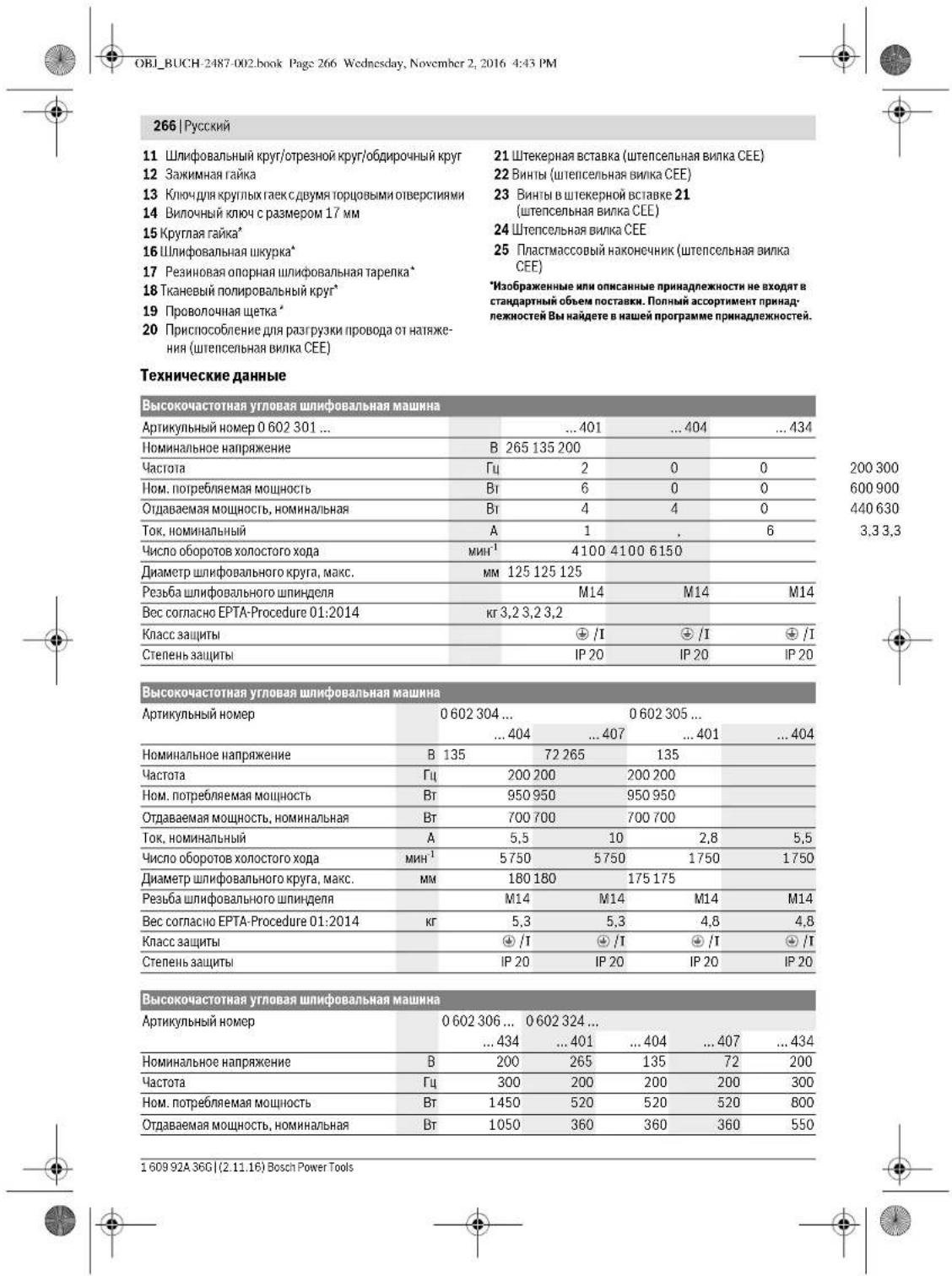
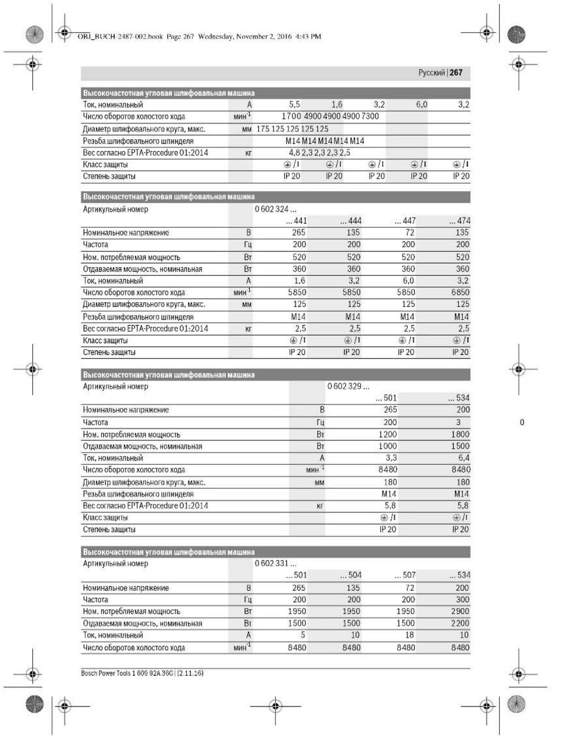
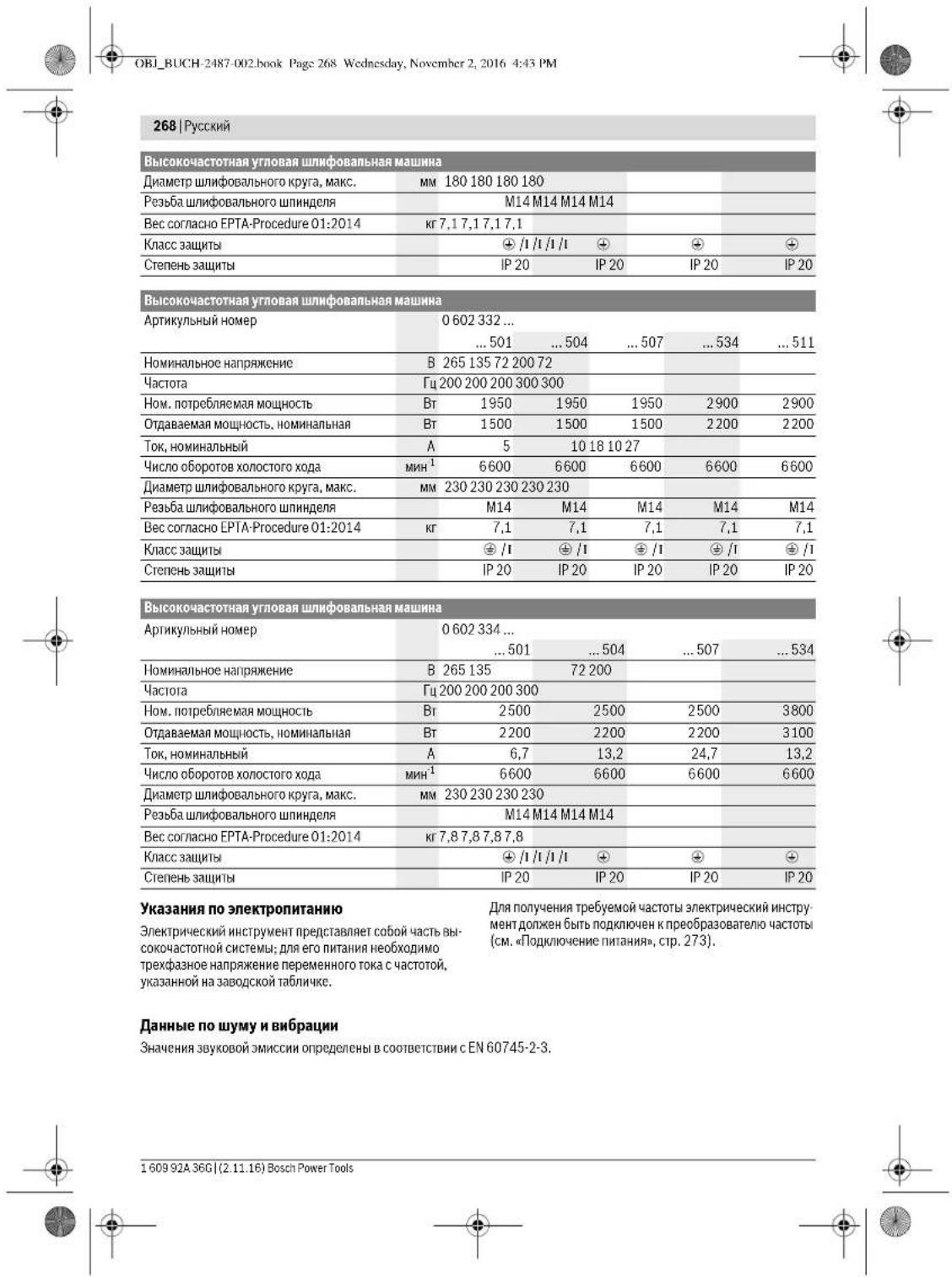



| 0.60230140. | 0.602301434. | 0.60230440. | 0.60230540. | |
| A-BBBeWeHnBiyuOBeHbIyMaHnCTpy-MeHTa CoCTaJIaNT TIIHHNOуPoBeHb 3ByKOBIO IaBIIeHnIyUroBeHb 3ByKOBIO MIoUHcTbIHeNtOpeBorPocHCTbI KIpyMeHnIte cpeDCTBa 3aUHTbIopranOB cnyxa! | ДБ(A) | 72 | 82 | 79 |
| ДБ(A) | 83 | 93 | 90 | |
| ДБ | 3 | 3 | 3 | |
| Суммая Вибрацья a₃ (Вектогая суm-Ма ТрEx NaHpAblenii) И поч鹿постьКОпrelдени B COOTBETCTBIMENCEN60745-2-3. | M/c² | - | 5,3 | 5 |
| M/c² | - | 2 | 2 | |
| Плноровanie: | ||||
| a₁ | M/c² | 3 | 3 | <2,5 |
| K | M/c² | 1,5 | 1,5 | 1,5 |
| Плноровanie дисkom с abpaэнbosушкpoKо: | ||||
| a₃ | M/c² | 3 | 3 | <2,5 |
| K | M/c² | 1,5 | 1,5 | 1,5 |
| 0 602 306 434 | 0 602 324 40. | 0 602 324 44. | |
| 0 602 324 464 | |||
| 0 602 324 474 | |||
| 0 602 324 434 | |||
| A-BaBSeHHeHb IyPoBeH bIyMa HnCtpymEnHa co- | |||
| cTaubJenTINuHNo | |||
| уPoBeH bIyKobO rO DaBHeHn | d5(A) | 82 | 77 |
| уPoBeH bIyKobO mOuHocTH | d5(A) | 93 | 88 |
| NeJIoCTOBepHocTh K | d5 | 3 | 3 |
| ПиMuHneIte cPrcTeBa 3aunHb OpranOB cnyxa! | |||
| СуМмApHЯ BvIbpaZma a1 (BekTopHЯ Cymma trpx | |||
| hAnpavBHeHm H nOgpeUHocTh K onpeDelenHb B | |||
| coOTBeTCTBm cEN 60745-2-3. | |||
| ШИнФОВANHE NOBEPXHOCTH (O6dNpKa): | |||
| a1 | M/c2 | - | - |
| K | M/c2 | - | - |
| ПОЛнРОВANHe: | |||
| a1 | M/c2 | <2,5 | 4 |
| K | M/c2 | 1,5 | 1,5 |
| ШИнФОВANHe dIscKOM cIbpa3HbHo IshkypKoH: | |||
| a1 | M/c2 | <2,5 | 4 |
| K | M/c2 | 1,5 | 1,5 |
| 0.602 329 50. | 0.602 329 534 0.602 329 511 | 0.602 331 5.. | 0.602 332 5.. | |
| A.Бзевений уровец улма Истору МERTA COCTABLANT HINNUCHO урочьberry Boyo Давлиения урочьberry Berry Boyo мошост通风 небочьерноctь K Пrimmenайе среadingва заuntы органов суха! | ДБ(A) | 85 | 87 | 86 |
| ДБ(A) | 96 | 98 | 97 | |
| ДБ | 3 | 3 | 3 |


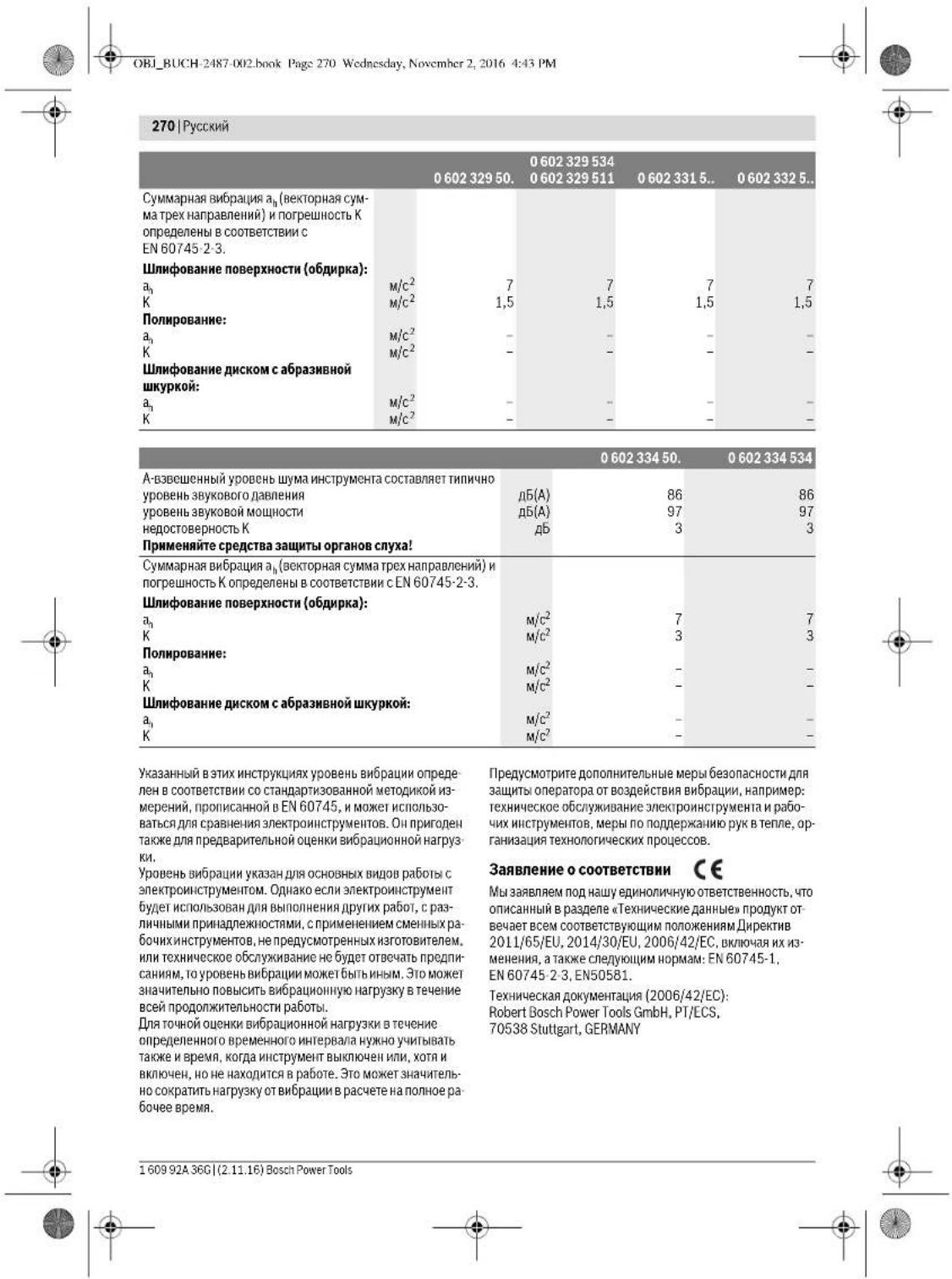

Henk Becker Executive Vice President Engineering
Helmut Heinzelmann Head of Product Certification PT/ECS
Robert Bosch Power Tools GmbH 705.38 Stuttgart, GERMANY Stuttgart, 01.01.2017
Always use the protective guard for cutting. Always use cutting guards with the protective guard for cutting with bonded abrasives (accessory).
The protective guard for cutting is mounted in the same way as the standard protective guard (see figure).
Selecting the auxiliary handle (19)

Assembly
Mounting the protective devices
General instructions
Before any work on the power tool, remove the battery from the power tool. Removing the battery prevents accidental starting of the power tool.
Note: The replacement of the grinding wheel is described in the section "Maintenance and Service". For the maintenance of the protective guard/ power tool, please contact the service center; addresses can be found in the service section.
Install the protective housing so that it prevents the opening of the damaged operator.
Installation: The locking lugs on the protective housings prevent the possibility of mounting the electric tool on protective housings not intended for it.
Protective housing for angle grinder (see Fig. A)
Valid for the following types:
-060230440. -06023295.. -0602324434 -06023315.. -060232444. -06023325.. -0602324 464 -06023345.. -0602324 474
Insert the protective housing with the locking lugs into the recess on the spindle neck of the electric tool. - Adjust the position of the protective housing according to the requirements of the work operation. - Secure the protective housing by tightening the clamping screw.
Protective housing for cutting
Valid for the following types:
-060230440. -06023295.. -0602324434 -06023315. -060232444. -06023325.. -0602324464 -06023345. -0602324474
Selection of auxiliary handle
The auxiliary handle reduces the level of vibration and ensures a more comfortable grip.
It is used with the electric tool only with the auxiliary handle.
- Screw the auxiliary handle 2 on the right or left of the gearbox housing depending on the type of work. Do not change the auxiliary handle during operation.
Valid for the following types:
-06023014. -060232440 -060230540. -0602306434
Installation:
Screw the protective cap onto the thread of the round nut until it stops against the thread of the spindle (M14).
- Make sure that the protective cap is installed with the auxiliary handle (see Installation of protective devices, p. 271). Tighten the round nut with the auxiliary handle against the spindle thread so that the cap is firmly seated against the surface of the power tool housing, while simultaneously pressing the spindle lock.
1609 92A 36G| (2.11.16) Bosch Power Tools


Russian 273
Removal
Unscrew the round nut with the auxiliary handle against the spindle thread, while simultaneously pressing the spindle lock, and remove the protective cap from the spindle thread.
Mounting the carbon brushes (see Fig. H)
Suitable for the following tools:
-0 602 304 40. -0 602 331 5..
-0.60232444 464 -0.6023325
474A434 -0.6023345
-0.6023295.
Installation:
Make sure that the carbon brushes are exactly aligned with the thread of the spindle (M14).
Before starting work, install the protective caps on the handles (see installation of protective caps, p. 271). Screw the cable gland (flat cable) onto the flat cable inlet of the tool, while holding the surface of the flat cable inlet with a wrench.
REMOVAL
Unscrew the cable gland from the flat cable inlet, holding the surface of the inlet with a wrench, while holding the cable with a suitable tool.
Dust extraction
Dust from materials such as paint containing lead, some wood types, minerals, and metals can be harmful. Contact with or inhalation of dust may cause allergic reactions or respiratory diseases in the operator or bystanders.
Certain dusts, such as oak or beech dust, are carcinogenic, especially when combined with wood treatment additives (chromate, wood preservatives). Material with asbestos must only be handled by specialists.
- Where possible, use a vacuum cleaner suitable for the material. Ensure good ventilation of the workplace.
- It is recommended to use a respirator with filter class P2. Follow the regulations applicable in your country for the materials being worked on.
Avoid contact with the workpiece. It may become hot.
Connection to the power supply
The electric tool must be operated with a residual current device (RCD) that trips on three-phase alternating current of the frequency corresponding to the data on the tool's nameplate.
The frequency converters available have different voltages, frequencies, secondary voltages, and rated powers. The choice of frequency converter depends on the type of electric tool used. Consult a specialist when selecting a frequency converter. The electric tool may only be connected to a special socket with a protective earth conductor. Before commissioning the tool, the special socket must be checked for a protective earth conductor with a green-yellow core.
In addition, the electric tool must be protected by a residual current device (RCD) with a rated residual current of 30 mA. The RCD must interrupt the rated current of the electric tool (see "Technical Data"). The RCD must trip within 0.1 seconds.
Follow the specified safety instructions and
the instructions in the operating manual for the protective device of the electric motor.
MOHTAX WTeNCBHOB BNNK CEE (see fig. 11-12)
Unscrew and remove the plug-in connector 21 from the housing of the plug-in socket CEE 24. Remove the cable gland 25 in accordance with the diameter of the special nut of the power tool and place the housing of the plug-in socket CEE on the special nut. - Perform the strain relief of the cable for the power supply line. - Unscrew the four small screws 23 in the plug-in connector 21 and insert the end of the brown wire L1 into the contact socket L1.
Insert the end of the blue wire L2 into the contact socket L2.
Insert the end of the black wire L3 into the contact socket L3, and the end of the yellow-green wire into the rear socket.
- Then firmly tighten the four small screws 23 in the plug-in connector 21 to secure these wires. Then screw the strain relief device for the power supply cable 20 onto the housing of the plug-in socket CEE 24 so that the cable end does not move. Insert the plug-in connector 21 into the housing of the plug-in socket CEE 24 and firmly tighten the two screws 22. Finally, check the protective conductor connection.

274 | Russian
Insert the plug-in socket CEE 24 of the power tool into the socket of the frequency converter. Now you can operate the frequency converter. Before commissioning the frequency converter, read the entire operating instructions. Finally, check the direction of rotation. Check the direction of rotation: The direction of rotation of the fan must match the arrow on the power tool. If the fan rotates in the wrong direction during the first commissioning (see switching on the power tool, p. 274), then immediately switch off the power tool and disconnect it from the power supply.
Then unscrew both screws 22 and remove the plug-in connector 21 from the housing of the plug-in socket CEE 24.
- Unscrew and remove the ends of the brown and black wires from the contact sockets. Insert the end of the black wire into the contact socket L1, and the end of the brown wire L1 into the contact socket L3.
- Then firmly tighten the four small screws 23 in the plug-in connector 21 to secure the wires. Insert the plug-in connector 21 into the housing of the plug-in socket CEE 24 and firmly tighten the two screws 22. Finally, check the protective conductor connection. - Connect the power tool to the power supply.
Working with the tool
Switching on the power tool
The power supply voltage must correspond to the data on the nameplate of the power tool. Check the power tool before use. The power tool must be securely installed and rotate freely. When switching on, the tool must run for at least 1 minute under no load. Do not use damaged or deformed power tools. Damaged or deformed power tools may break and cause injury. The manufacturer's switch-on and switch-off cycles are based on the rated operating time, taking into account the possibility of uncontrolled restart. Before restarting the power tool, check the power supply (see "Connecting to the power supply", p. 273).
Always connect the power tool to the frequency converter before connecting the frequency converter to the mains.
Switch on the power tool only when you are ready to work with it.
Switching on and off the frequency converter must be done by starting and stopping the frequency converter, not by switching the power tool on and off. Follow the instructions in the operating manual for the frequency converter.
Switching on and off the power tool with a protective switch (see Fig. J1)
Applicable to the following types:
- To switch on the power tool, press the switch 1 forward. - Lock the switch in the ON position by pressing the lock button. To switch off the power tool, release the switch 1. With the switch locked, press the switch 1 slightly to the rear and then release it.
Switching on and off the power tool with a protective switch (see Fig. J2)
Applicable to the following types:
-06023014.. -06023295.. -060230440. -06023315.. -060230540. -06023325. -0602306434 -06023345..
Working with the router
With the router (accessory) you can also work on convex surfaces (contour milling).
The router produces significantly less noise, creates less dust and lower temperatures than larger routers.
Cutting metal (see fig. K)
Always use the protective guard for cutting with bonded abrasives.
The cutting disc must be suitable for the material being cut. Do not apply pressure to the cutting disc, do not tilt or jerk it.
Do not use cutting discs for grinding.
Always guide the power tool with the cutting disc perpendicular to the direction of rotation. If the disc becomes jammed, switch off the tool immediately and remove the plug from the socket.
When cutting pipes or profiles, use a suitable support or guide.
Cutting with a cutting disc
When cutting, ensure sufficient dust extraction. Use a dust mask. This power tool is intended for dry cutting and dry sanding only.
For cutting, always use a suitable cutting disc. To avoid overheating, use a guide with a cutting aid. Work only with a dust mask and additional dust extraction. Do not allow sparks to come into contact with flammable materials. The manufacturer offers suitable accessories.
Switch on the power tool and place it in front of the workpiece with the guide. Guide the power tool smoothly, according to the material being cut.
When cutting hard materials, e.g., concrete with a high aggregate content, the diamond cutting disc may overheat. A rotating diamond cutting disc glows red-hot. In this case, stop the cutting process and let the diamond cutting disc cool down at maximum speed for a short time. A significant decrease in cutting performance and a glowing disc indicate that the diamond cutting disc is blunt. You can resharpen the diamond cutting disc with short cuts in an abrasive material (e.g., silicate brick).
Setting the cutting depth
For load-bearing walls, the regulations of DIN 1053 part 1 or the corresponding national regulations apply. These instructions must be strictly followed. Before starting work, consult the responsible structural engineer or architect.
Dust extraction
Never use cutting discs for grinding!
The circle from 30° to 40° to the workpiece you will get the best results with single grinding. Turn the power tool with the grinding wheel against the workpiece and back. During this the grinding wheel does not heat up, does not change its color and does not leave burn marks.
Grinding with a grinding wheel on a rubber backing pad
The choice of the suitable grinding wheel depends on the material to be processed. Bosch offers a range of grinding wheels of different quality, suitable for the corresponding backing pad. It is recommended to use the appropriate grinding wheel.
Grinding with a fiber disc
The grinding aid for grinding the surface of the material to be processed with a fiber disc is distributed over the entire surface to be processed. If the grinding is carried out in several passes with the same grit, the grinding aid becomes finer, so the grinding aid should be used with a new fiber disc. The surface of the material to be processed must be checked before each subsequent grinding pass.
Maintenance and service
Maintenance and cleaning
Before any work on the power tool, remove the battery from the power tool. The power tool is protected against unintentional starting. To ensure safe operation, keep the power tool and the ventilation slots clean. In extreme conditions, always use a dust extraction system if possible. Check the ventilation slots and the protective device (PRCD) regularly. If the power tool is used in dusty conditions, the dust may reduce the protective effect of the power tool.
Bosch Power Tools 1609 92A 36C (2.11.16)


276|Russian
Regularly measure the no-load speed of the angle grinder. If the measured value differs from the specified no-load speed by more than 10% (see Technical Data), the power tool must be checked by a Bosch service center. If the no-load speed is too high, the power tool may be damaged, and if it is too low, the working performance is reduced. Use only original spare parts. Before each use, check the power tool for damage. To avoid any risk, do not repair, but replace with new parts. Have maintenance and repair carried out only by qualified personnel. This ensures the safety of the power tool.
Clean the sockets, plugs and cable plugs of the power tool with a dry cloth that does not have lint, remove dust and particles.
After 150 working hours, lubricate the gearbox with a mild solution. Follow the instructions for the lubricant. After that, have the gearbox checked by a Bosch service center. After the first 300 working hours, repeat the procedure.
The Bosch service center performs this work in all branches.
Please send your power tool to the Bosch HIN authorized service center for repair.
Careful handling and disposal of accessories
Accessories
You can find a comprehensive program of quality accessories in the Internet at www.bosch-pt.com and www.boschproductiontools.com or from your specialized dealer.
Service and consultation on product use
The service center will answer all your questions regarding repair and maintenance of your product and spare parts. You can find detailed information on spare parts at the following address:
www.bosch-pt.com
The Bosch team of employees, providing consultation and product use, will gladly answer all your questions regarding our products and their accessories.
Please always quote the 10-digit article number on the nameplate for all inquiries and spare parts orders.
Do not dispose of power tools in household waste!






278|Ukrainian
Safety instructions for jigsaws. When using the power tool, observe the following safety instructions to reduce the risk of electric shock, fire, and personal injury. Keep the power tool away from rain and moisture. Water entering the power tool increases the risk of electric shock. Do not use the cord for carrying or hanging the tool, or for pulling the plug from the outlet. Keep the cord away from heat, oil, sharp edges, or moving parts. Damaged or entangled cords increase the risk of electric shock. When operating a power tool outdoors, use an extension cord suitable for outdoor use. Use of a cord suitable for outdoor use reduces the risk of electric shock. If operating the power tool in a damp location is unavoidable, use a residual current device (RCD) protected supply. Use of an RCD reduces the risk of electric shock. Always wear safety glasses and a dust mask. Wear hearing protection during prolonged operation. Secure the workpiece. Use clamps or a vice to hold the workpiece. This is safer than holding it by hand. Keep your hair, clothing, and gloves away from moving parts. Loose clothing, jewelry, or long hair can be caught in moving parts. If dust extraction and collection equipment are provided, ensure they are properly connected and used. Use of dust collection can reduce dust-related hazards.
Safety
Be careful, follow the instructions below to work safely with the power tool. Do not use the power tool if you are tired or under the influence of drugs, alcohol, or medication. A moment of inattention while operating the power tool may result in serious personal injury. Use personal protective equipment. Always wear eye protection. Protective equipment such as dust mask, non-skid safety shoes, hard hat, or hearing protection used for appropriate conditions will reduce personal injuries. Prevent unintentional starting. Ensure the switch is in the off-position before connecting to power source, picking up or carrying the tool. Carrying power tools with your finger on the switch or energizing power tools that have the switch on invites accidents. Remove any adjusting key or wrench before turning the power tool on. A wrench or a key left attached to a rotating part of the power tool may result in personal injury. Do not overreach. Keep proper footing and balance at all times. This enables better control of the power tool in unexpected situations. Dress properly. Do not wear loose clothing or jewelry. Keep your hair, clothing, and gloves away from moving parts. Loose clothes, jewelry, or long hair can be caught in moving parts. If devices are provided for the connection of dust extraction and collection facilities, ensure these are connected and properly used. Use of dust collection can reduce dust-related hazards.
Additional safety instructions for jigsaws
Do not use attachments. Use only attachments intended for the intended work. With sharp attachments, you will get better work results with less risk. Use attachments only in the specified power range.
Do not use power tools with a damaged switch. A power tool that cannot be turned on or off is dangerous and must be repaired. Before adjusting, changing accessories, or storing power tools, disconnect the plug from the power source and/or remove the battery pack. Such preventive safety measures reduce the risk of accidental starting of the power tool. Store idle power tools out of the reach of children and do not allow persons unfamiliar with the power tool or these instructions to operate the power tool. Power tools are dangerous in the hands of untrained users. Maintain power tools. Check for misalignment or binding of moving parts, breakage of parts and any other condition that may affect the power tool's operation. If damaged, have the power tool repaired before use. Many accidents are caused by poorly maintained power tools. Keep cutting tools sharp and clean. Properly maintained cutting tools with sharp cutting edges are less likely to bind and are easier to control. Use the power tool, accessories and tool bits etc., in accordance with these instructions, taking into account the working conditions and the work to be performed. Use of the power tool for operations different from those intended could result in a hazardous situation.
Service
Have your power tool serviced by a qualified repair person using only identical replacement parts. This will ensure that the safety of the power tool is maintained.
Safety instructions for circular saws
General safety instructions for power tools
The following applies:
280|Ukrainian
Regulating the ventilation of the power tool. Ventilation openings often cover moving parts, and they can be a source of danger. Do not use the power tool near flammable materials. Such materials can ignite. Do not use accessories that require liquid coolant. Using water or other liquid coolants may result in electric shock.
Residual risks
Always use the auxiliary handle, if supplied, for maximum control over kickback torque or reaction torque. Never use the power tool with one hand. Loss of control can cause serious injury. Kickback is a sudden reaction to a pinched or snagged rotating accessory, such as a grinding wheel, backing pad, or wire brush. Pinching or snagging causes rapid stalling of the rotating accessory, which in turn forces the uncontrolled power tool to be pushed in the direction opposite of the accessory's rotation at the point of binding. For example, if an abrasive wheel is snagged or pinched by the workpiece, the edge of the wheel that is entering the pinch point can dig into the surface of the material, causing the wheel to climb out or kick out. The wheel may either jump toward or away from the operator, depending on the direction of the wheel's movement at the point of pinching. Abrasive wheels may also break under these conditions. Kickback is the result of power tool misuse and/or incorrect operating procedures or conditions and can be avoided by taking proper precautions as given below. Maintain a firm grip with both hands on the power tool and position your body and arm to allow you to resist kickback forces. Always use auxiliary handle, if supplied, for maximum control over kickback or reaction torque. If possible, avoid kickback by using safety equipment such as a guard. Never place your hand near the rotating accessory. The accessory may kickback over your hand. Do not position your body in the area where the power tool will move if kickback occurs. Kickback will propel the tool in the direction opposite to the wheel's movement at the point of snagging. Use special care when working corners, sharp edges, etc., to avoid snagging and sudden kickback. Keep the power tool clean and free of dust and debris. Do not use the power tool if the switch does not turn it on and off. Any power tool that cannot be controlled with the switch is dangerous and must be repaired. Always use the correct type of grinding wheel for the tool and the application. Do not use a wheel that is damaged or cracked. Before each use, inspect the wheel for cracks or damage. If the wheel is damaged, do not use it. Do not use the power tool if it vibrates excessively. Check for loose parts and tighten them before use. Do not use the power tool if it is damaged or not working properly. Have the power tool serviced by a qualified repair person using only identical replacement parts. This will ensure that the safety of the power tool is maintained. Do not modify the power tool in any way. Do not use the power tool for purposes other than those intended. Always wear eye protection and a dust mask. Use of personal protective equipment, such as safety glasses, dust mask, non-skid safety shoes, hard hat, or hearing protection used for appropriate conditions will reduce personal injuries. Do not overreach. Keep proper footing and balance at all times. This enables better control of the power tool in unexpected situations. Dress properly. Do not wear loose clothing or jewelry. Keep your hair, clothing and gloves away from moving parts. Loose clothes, jewelry or long hair can be caught in moving parts. If devices are provided for the connection of dust extraction and collection facilities, ensure these are connected and properly used. Use of dust collection can reduce dust-related hazards. Do not use the power tool while you are tired or under the influence of drugs, alcohol or medication. A moment of inattention while operating power tools may result in serious personal injury. Do not use the power tool if the switch does not turn it on and off. Any power tool that cannot be controlled with the switch is dangerous and must be repaired. Always use the correct type of grinding wheel for the tool and the application. Do not use a wheel that is damaged or cracked. Before each use, inspect the wheel for cracks or damage. If the wheel is damaged, do not use it. Do not use the power tool if it vibrates excessively. Check for loose parts and tighten them before use. Do not use the power tool if it is damaged or not working properly. Have the power tool serviced by a qualified repair person using only identical replacement parts. This will ensure that the safety of the power tool is maintained. Do not modify the power tool in any way. Do not use the power tool for purposes other than those intended. Always wear eye protection and a dust mask. Use of personal protective equipment, such as safety glasses, dust mask, non-skid safety shoes, hard hat, or hearing protection used for appropriate conditions will reduce personal injuries. Do not overreach. Keep proper footing and balance at all times. This enables better control of the power tool in unexpected situations. Dress properly. Do not wear loose clothing or jewelry. Keep your hair, clothing and gloves away from moving parts. Loose clothes, jewelry or long hair can be caught in moving parts. If devices are provided for the connection of dust extraction and collection facilities, ensure these are connected and properly used. Use of dust collection can reduce dust-related hazards. Do not use the power tool while you are tired or under the influence of drugs, alcohol or medication. A moment of inattention while operating power tools may result in serious personal injury.
Use only undamaged grinding wheels and undamaged discs. Such tools often cause sparks and electric shock. Before use, check that the grinding wheel is mounted on the electric grinder and that the guard is installed in accordance with the grinding wheel. A grinding wheel that is not mounted on the electric grinder is dangerous and can be thrown off. The protruding grinding wheel must be mounted in such a way that its working surface protrudes beyond the edge of the guard. An incorrectly mounted grinding wheel that protrudes beyond the edge of the guard is not protected in this way. The guard must be installed on the electric tool and adjusted so that the maximum possible part of the grinding wheel is exposed to the operator, but the operator is protected from the grinding wheel. The guard protects the operator from fragments, sparks, and accidental contact with the grinding wheel, and from sparks that can cause injury. The grinding wheel can be used without interruption. Do not use the side surface of the wheel for grinding. The wheel is designed for grinding with the edge of the wheel. It can be damaged by excessive pressure. Always use a new grinding wheel and check the disc for cracks and damage. The disc must be mounted on the grinding wheel in such a way that it is not dangerous. The disc can be damaged by excessive pressure. The grinding wheel can be used for cutting. Do not use a damaged grinding wheel that has been dropped. The grinding wheel for cutting is not designed for side pressure and can break.
Special precautions for cutting with grinding wheels
Avoid jamming the cutting wheel or applying excessive pressure. Do not cut too deep. Excessive pressure on the cutting wheel increases the load on the wheel and its tendency to tilt or jam, and thus increases the risk of breakage or damage to the grinding wheel. Avoid cutting from the front and back of the wheel. If the cutting wheel is pressed into the material in the cut, when the electric grinder is turned on with the wheel, it can throw sparks at you.


Ukrainian 281
The blade is a circular saw blade designed for cutting work. Before use, check the blade for cracks or damage. If you notice any cracks, do not use the blade until it has been repaired or replaced. Do not use the blade if it is damaged or worn. Always wear safety goggles when using the blade. Keep the blade clean and free of debris. Do not use the blade on materials that are not recommended for cutting. Be careful when cutting in tight spaces or near edges. A damaged blade may cause injury or damage to the workpiece.
Special precautions when using the blade
Do not use damaged or worn blades. Follow the instructions for use and maintenance of the blade. A damaged blade, with cracks or missing teeth, can cause injury or damage to the workpiece. Replace the blade if it is damaged.
Special precautions when using the blade. Do not allow the blade to come into contact with the workpiece before it is fully up to speed. Keep the blade sharp. A dull blade can cause the saw to bind or kick back, which may cause injury.
Special precautions when using the blade
Be aware that the blade may become hot during use. Do not touch the blade immediately after use. Allow it to cool down. If the blade becomes too hot, it may warp or become damaged. It is recommended to use a blade with a lower tooth count for cutting materials that are prone to overheating. Always use the correct blade for the material being cut.
Additional precautions
Wear safety goggles!
Warnings about entering pipes or electrical wiring when using power tools with attachments or accessories. Electrical wiring can cause electric shock and injury. Gas pipe entry can cause an explosion. Water pipe entry can cause material damage or electric shock. Disconnect the power supply before making adjustments or changing accessories. This will prevent accidental starting of the tool. Do not touch the rotating parts, they are hot. The part becomes hot after work. During operation, hold the tool with both hands and keep a firm grip. With both hands you can control the power tool. Do not use damaged materials. Use the auxiliary handle to control the material during operation. Unplug the power tool from the mains before making any adjustments. In the socket, the plug must be inserted correctly.
Safety instructions for high-frequency power tools
To obtain the safety instructions, contact the manufacturer of the tool. The instructions can be obtained from the manufacturer. It is important to follow the instructions to avoid electric shock, fire, or injury. The automatic shutdown device may not work if the tool is used with materials that conduct electricity. The automatic shutdown device may not protect against electric shock. The automatic shutdown device must only be installed by specialists. Only in this way can the safe operation of the tool be ensured. The frequency converter must be checked regularly. The power tool can only be operated with the specified voltage. The current must be calculated according to the nominal current of the power tool (see technical data).

282|Ukrainian
Installation of the switch and adjustment of the tool must be carried out by qualified personnel. Use only the original cable. Before using the power tool, check the cable and plug for damage. Do not repair the cable yourself; have it replaced by a specialist. Damaged cables can cause electric shock.
284 Ukrainian
| Bar a lipoïsique 20 EPIA-Procedure 01:2014 | xr 2,5 2,5 2,5 2,5 | |||||
| Klaac jaxicity | A / A / A | |||||
| Cryotina, tachy | IP 20 | IP 20 | IP 20 | IP 20 | ||
| Apocrymaiail nocep | 0.602 329 ... | |||||
| Hoi, nangya | B 265 200 | |||||
| Hacora | Tq | 2 | 0 | 0 | 3 | 0 |
| Hoi, cthonkaiia noryoicta | Br | 1 | 2 | 0 | 0 | 1800 |
| Hokkaido nongyaknoryoicta | Br | 1 | 0 | 0 | 0 | 1500 |
| Hokkaido crypu | A 3,3 6,4 | |||||
| Klauicid, oifcrin na xionyamoly kvy | Xm#n, | 8480 | 8480 | |||
| Mao, diamerp undyaknoro kpyra | M# 180 180 | |||||
| Piaide uidyanbato rno unueen | M14 | M14 | ||||
| Bar a lipoïsique 20 EPIA-Procedure 01:2014 | K7 5,8 5,8 | |||||
| Klaac jaxicity | /1 | /1 | ||||
| Cryotina, tachy | IP 20 | IP 20 | ||||
| Apocrymaiail nocep | 0.602 331 ... | |||||
| Hoi, nangya | ... 501 | ... 504 | ... 507 | ... 534 | ||
| Hacora | B 265 | 135 | 72 | 300 | ||
| Hacora | Tq 200 | 200 | 200 | 300 | ||

Ukrainian 285
| Ви这样做 не那么容易做到 Бага вдacons做不到 EPTA-Procedure 01.2014 | Кr 7,17,17,17,17,1 | ||||
| Клас зхису | ©/I | ©/I | ©/I | ©/I | ©/I |
| Стейнь зхису | IP 20 | IP 20 | IP 20 | IP 20 | IP 20 |
High-frequency rotary hammer
| Артыкунший Homep | 0 602 334 ... | |||
| ... 501 | ... 504 | ... 507 | ... 534 | |
| Hom. Hanpyra | В 265 135 72 200 | |||
| Частora | ГИ 200 200 200 300 | |||
| Hom. сponжва на поожнICTь | Вт 2500 2500 2500 3800 | |||
| Hominaльна видна поожнICTь | Вт 2200 2200 2200 3100 | |||
| Hominaльный сктуМ | A 6,7 13,2 24,7 13,2 | |||
| Кільские оберпя на:xолостому xody | хов.1 | 6600 6600 6600 6600 | ||
| Мас.диам耗费алъно крура | MM 230 230 230 230 | |||
| Рльбашидевалъношения | M14 M14 M14 M14 | |||
| Bara bidingoю do EPTA Procedure 01:2014 | кг 7,8 7,8 7,8 | |||
| Клас зхису | ©/I | ©/I | ©/I | |
| Стуниь зхису | IP 20 | IP 20 | IP 20 | |
Operating instructions
The power tool is designed for high-frequency operation and requires proper handling to ensure safety and efficiency.
Ukrainian 287
Teixhihuaoyemtuaia (2006/42/EC): Robert Bosch Power Tools GmbH, PT/EC5, 70538 Stuttgart, GERMANY
Henk Becker Helmut Heinzelmann Executive Vice President Head of Product Certification Engineering PT/ECS

Robert Bosch Power Tools GmbH 70538 Stuttgart, GERMANY Stuttgart, 01.01.2017
MOUNTING
MOUNTING Protective devices
For important instructions
Before starting any work on the power tool, remove the battery from the power tool. If the power tool is accidentally switched on, there is a risk of injury.
Note: When using the power tool, always hold it firmly with both hands and ensure you have a stable stance. If the protective devices are damaged, immediately have the power tool repaired by a qualified specialist. For addresses, see the "Service and Customer Advice" section.
The protective guard must be installed so that sparks do not fly towards the operator.
Note: When using the power tool, always hold it firmly with both hands and ensure you have a stable stance. If the protective devices are damaged, immediately have the power tool repaired by a qualified specialist. For addresses, see the "Service and Customer Advice" section.
Protective guard for grinding
The following types are available:
-060230440. -06023295.. -0602324434 -06023315.. -060232444. -06023325.. -060234464 -06023345.. -0602324474 Attach the protective guard with the clamping screw. Ensure that the guard is correctly seated and securely fastened before use. Adjust the guard to the required working position.
Protective guard for cutting
The following types are available:




__SUPPIMER__
Ukrainian 288
Instructions for using the specified abrasive tools are required. For sharpening stones, use the sharpening tool with a straight (flat) surface.
The sharpening tool is used only according to the standard sharpening tool (DIN, MA).
Ukrainian 289
Mounting the grinding tool (see Mounting grinding, cutting, or polishing discs, page 288). The spindle 5 is locked with the spindle lock.
Mounting the rubber backing pad (see figure)
Proceed as follows:
Mounting
When mounting the grinding tool, the spindle lock must be engaged (see Mounting the grinding tool, page 207). Mount the rubber backing pad 17 and the grinding disc 3. - Place the grinding disc 16 on the rubber backing pad. - Mount the clamping nut 15 on the spindle. - Tighten the clamping nut with the two-pin wrench 13, while holding the spindle with the two-pin wrench 14. The grinding disc must be flush with the surface of the rubber backing pad.
Ensure that the disc 15 is fully seated in the recess of the rubber backing pad, so that it does not protrude beyond the grinding disc during grinding.
Mounting the pressure gauge: Turn the large 15-year key and press the button 13 from the pressure gauge, pressing the 14a key on the surface of the button. - The pulses are generated by the pressure gauge.
Mounting the pressure gauge (Fig. Man. G)
It is distributed as follows:
-06023014. -060232440 -060230540. -0602306434
Mounting
Make sure that the pressure gauge fits into the mounting hole (M14).
Insert it, then tighten the nut by hand. The instructions (see. Mounting the protective cover, page 27). Screw the pressure gauge 18 onto the mounting thread until it is flush with the surface of the mounting hole; then tighten the nut 14 on the surface of the mounting hole.
Removal
To remove the pressure gauge, if it is stuck on the thread, take it with the key by the surface of the nut, and then press the key 14 on the surface of the nut on the mounting thread.
Disposal/Recycling/Scrap
For such materials, e.g., coatings containing lead, certain wood preservatives, minerals and the like, may be hazardous to health. Touching or inhaling them may cause or aggravate allergic reactions or diseases of the respiratory organs. Wear protective gloves and a dust mask when handling such materials. Dispose of them in accordance with the regulations for the disposal of hazardous materials (chromate, protective agents). Materials containing these must be disposed of by a specialist. If possible, use materials that are environmentally friendly. Make sure to dispose of waste properly.
Dispose of used materials in accordance with the regulations in your country. Use the appropriate waste disposal containers. Do not dispose of them carelessly.


290 | Ukrainian
Connection to power source
The electric tool is designed for converting the frequency of the supply voltage. The frequency converter is used to change the frequency of the electric current. The frequency converter can be used with different types of motors, both single-phase and three-phase. The selection of the frequency converter depends on the type of electric tool. When selecting the frequency converter, it is recommended to consult a specialist or the manufacturer Bosch.
The electric tool must be used with a special cable for connecting to the power supply. To use the electric tool, the special cable must be properly installed. The cable must be marked accordingly.
Before starting work, the electric tool must be checked for standard safety regulations. The safety regulations for electric tools must be followed according to the instructions. The safety regulations for electric tools must be followed at least once a year. The safety regulations must also be followed by the operator, as well as the instructions for the safety of electric tools.
Installation of the cable (see Fig. 11-12)
- Insert the cable through the opening 22 and into the cable gland 213 on the housing of the cable gland 24.
- Attach the protective cover 25 according to the diameter of the special cable of the electric tool to the housing of the cable gland 24 and the special cable.
- Tighten the four screws through the element of the compensator to the nut 20.
- Insert the four screws 23 into the cable gland 21 and tighten.
Connect the cable wires to the terminals L1, L2, L3, and the ground terminal.
Connect the cable wires to the terminals L1, L2, L3, and the ground terminal.
Connect the cable wires to the terminals L1, L2, L3, and the ground terminal.
Also connect the cable wires to the ground terminal and the protective conductor.
Then tighten the four screws 23 on the cable gland 21, and secure the four screws. Tighten the compensator nut 20 to the cable entry so that the cable is firmly held. Insert the cable gland 21 into the housing of the cable gland 24 and then tighten the cover 22. The cable gland 24 of the electric tool must be connected to the frequency converter.
The frequency converter can be used with the electric tool.
The frequency converter is described in the operating instructions for the frequency converter.
Picn cyoro nepebipte hnpam o6eptaHn!
Ipebipka Hanpmy o6epaHH
Hampam o6epranu huiyabylhoro yinhuide naobnene bliouoatratai, 30j6pwnai Haeektoipcrpymnti.
KJIOIUIIFyBaJIHHI IHHHII HIIuac NpIeHOYUIMKHeHHI (JH. BMHKAHNHBMKHANH EeKTKPOrHPaIy,cTrop.291) o6ePraTuC y HnepAHIbHOMy HapmKy,HeraiHO BMKnHITb EeKTKPOIHCTpyMeHT i BiA'cHAnthe Horo Bi, dKepeLa KMBIEHNI.
3BNYbIyIcITbI,6bIaIbIaIbIITb22I bIbIMtIitrrnncIbIy I BCTABY 21 aKOPNVCUITcEREE CEE 24. BHHIMt KAcBcHNI KInHeBRI tRnKuOpHO T aKoHnHeBoJ Hx3 XnHKTAnKTHnHnHn - IOTIM BCTABRE KABENH KyINBey RIN3y YOHPOI JIJI L3 b KOHTAKHE RIN3oL1, a KaBENH KyINBey RIN3y KOHNHEOBJIKI L1 B KOHTAKHE RIN3oL3. MiHIOIaTHITb MJIeJIbIKIINHIITN 23 aIITeICJIbIKI BCTABU 21,0IO 6aKIFcYBaTIKAn KJIN. Bacteine tectyphae bacteay 2421 na Mieite bokmyci turrencere CEE. 24Mioi zoatrtitb. 6oNdi aTnH 22 -ПИСВ IБОТО ПЕРIPITE павилььнICTь рбовTNЗHOTOrI dpoTy. 3-Hohny MIA eHaHnre eEeKrPoHHCTpyMeHT Do Jepepa KJUHeHHa
Po6ota
Noataokpo60TH
Hanpyra i vactota dxcepena ctpmy nobHHi bianobadin daHHMa h 3ab0cbkib Ta6nHui j e nektoptcHPTMya.
Ipebeipire uhiybalni hi hctpymentn nepeed ecnnyataucio. uhiybalnn hi ctpyment mac 6ytb 6e20anHBO MTOHTOBAH a biHb o6epatranh. He BHKOPHCOTyTe noKoJcHt Ta Kepyrni uhiybalni hi ctpyment ao kto, uio cnHb bibpyot. IohkOJcHt Hihybalni hi ctpymertn MoKytL MaTnCt i c npuHvBTH n Tinechi ykuokKeHHa. KIOO npR yBMKHcHOMyBMMNCAU1 eNEkTePOINCTPmEHTHeNOHbAOpnHHNtBpo6Oy, BMMNKTb BMMNKaT. TaKHM YHOM IOHepeJAcTbCS HEKOHrPToJIbONAE yBMKHeHnIHCTpyMeHTa.Ipeep THM IK 3HOBY MHKATN eEKeTOPICHTPMEnI, IpepeIptre IIAPAeMTPr HJbEHNH (DInh. IIKIOuEHnO dKepeHa KJBILHEH), CToP.290). 3abzndcnocatky nd'cdnythe eneKtpoiHCTpymEno nepeTebOpBoua cactothn IH NNEOTIN d'cdhyTe nepeTebOpBau cactothn Do eneKtpomepexi.
3MpkyaHbHa 3aoaJdKeHHe enKtpoeepeRi BmKaIte eKtoPiocHTpyMeHr TnHHe ToDi, KOHN B36HpAetec, KOKPCTBYATHCn HIM.
OBI_BUCH-2487-002.book Page 291 Wednesday, November 2, 2016 4:43 PM
YkpaHcbka 291
YBMKHeHHBMMKHeHHNepetbOpobauaactOTN
CNoTuKyT NOrPi6HbY BMiHcyNTpeBtPOBbAaCTOHTI IJIHO NT BIMnKAtn eKeTpOPIHcPTPMET.
DITMHYTEIINPbUOIMCYRPKJI3ECKUYATAJIIENPETBOPIBAAACTOH.
If the device is used by specialists or experts, it is necessary to bring it in for repair.
The user manual should be kept together with the device.
If the device is used from the beginning, it can be connected to an electrical network, or to an electrical network with a grounding conductor, or to an electrical network with a grounding contact.
Device safety
The device is installed in a dry and well-ventilated place. If the device is damaged or has a defect, it should be brought in for repair. The device should be protected from water, gas, or other liquids. Do not use the device if it is damaged. When connecting the device to the electrical network, follow the safety instructions. It is forbidden to use the device in this case.
Electrical safety
The device must be connected to a power outlet. It is possible to use an extension cord. When connecting the device to the electrical network, ensure that the grounding conductor is connected. The outlet must be grounded and have a protective contact. Do not use the device if the cord or plug is damaged. If the cord is damaged, it must be replaced by the manufacturer or a qualified person. Do not touch the device with wet hands. Do not pull the cord to disconnect the device. Do not use the device near water. If the device is not working properly, disconnect it from the power supply. Do not use the device if the cord is damaged. The cord must be replaced by the manufacturer or a qualified person. Do not use the device in a place where it can be exposed to water or moisture. Do not use the device if the cord is damaged. The cord must be replaced by the manufacturer or a qualified person.
Aamap kayinci3iri
Cak Boyn, Hien TtXaHAnb3Fa Abykua KaHin 6enin, 3eKnTp Kypanb nptim naanabnB13. 4uapuaar XaFdAaiHmece enitkiu, AnkoronB
Hemece aepi acebi hda 3nKtp Kypanbni naindanabhbi.3neKTP Kpandnbai naianahya dekyntbkaababcbdikkKaTbKapaakatanynapra anbin KenyIyMmKih.
KekeckatbHKnHMJxHeepaBIMkopFaBHI Keinipik3KnI3.3NktpKanTyprHemeCe naiDanyahyVaShaunHcTbWAnTbKuB,cbpydAa KaCtainbHbBateKcKaTaNbUeHMeCEe Kynak CaTaTbBcNChbTeKkeKOpFAhBxabYbTkApbHKNo KaPakattayKaynIHtemedetEi BaiKaycbn naidanahyaan aynak 60bn3.3neKtp KpyanbHnTKoKa xheHemee AkyMnyTropa Kocya, OHk TepreIbe Hemece anIbXyPrrnde, euiypni 60ynba Ka3xetkiin3.3neKtp KpyanbHk Tepin TyraHda, 6apMaKbI kAkpATKhIta Yctay Hemepe KpybHbKocnyi KyKeTOKKa Ccy,KzataaHIM OKHranaI bKnIy MyMkhN. 3NeKtp KpyanbH KocyaH anbH petteHIN acnantapBx Hae JhaRk KInTeP HAnCTaBbH. AHAnatbH 60neKe TpyrA hAn HEme C KeJ kApakAttAnnpra Abln Kenyi MymKnH. Kanbcbsde He Kinyinde Tpymaib3. Tipek Kyide TpybIn, apKaaHAn 03H3di ceHIMdi YCTaH3. Ocbnai c3 KyTnerE HxaraJaA 3neKtP KypanDbjXkCbpak BaknaihCbia. Kymbica kapaamdbkimkniz.KeHemece cohdi KHMKmJ3. 1aawbHbI2ds, kMxhe KOfarnTb KoFalmnb6bnweKTepeH anbc yctanb3.KeHKM, OeKeH HEMeCe yabn wau KoFalmnb6bnweKTepre THOYMKNH 1AHCOPBWHJHwAHTKbWJXab6bTKapbl KpyPAHDA,ONAPBbKcOJIbNAHbIbHAKe HPyBCnA hNanDhMyHwCeb6BHeONbTHaKayInepn3aa3aTbn.
3neKtp KypanapbIn naiDAnay KHe Kty
Kypandba cakaek kxtemek3. Xymbcsih3yuih Xapamdbn 3neKtp KypanbH nainanahnb13. Xapamdbu 3neKtp KypablmH Kepekii Ymblc aHaBnD aDpblc api ceHmlj yMblc icTeHc3. AaxbpaTkiBbIkybpEmc3neKtpkypanbln naindanahabbi3.Kocyra HeMece bipipyre BonmaTbHn 3neKtpkypanblKayintiBobn,ohjKeHcyKaKTe Bona. Kabdkappey6nwekeptinamactbipy Hemece Kpaanbl annil KOJDAH anBihA hpi Ppdo poteKaadh HfapbH3xHe/Hemece AKKyMyntopbl Anbl TactaH.5 byn caktkapeketi 3nektpr kpandi, bainkaycuB KocunuHa xon bcpmei. NanabnBnBnBnBnBnBnBnBnBnBnBnBnBnBnBnBnBnBnBnBnBnBnBnBnBnBnBnBnBnBnBnBnBnBnBnBnBnBnBnBnBnBnBnBnBnBnBnBnBnBn 3NeKtp KypandapnByKnBb KyTniJi. KoFzAmnbl BenwekeptdKepepriscIcteyineHaKeTennin KaNmaybHa, BenwekeptdIkyacbSHeMece
160992A36G|(2.11.16) Bosch Power Tools

OBI_BUCH-2487-002.book Page 295 Wednesday, November 2, 2016 4:43 PM
Kazakua1295
3akbIMdAmarH6onybHa,3neKtp KypanbHbH 3akbIMdAmarHbHa K03XeTki3iJ3.3akbIMdAmH 6bnwckrepi6kpynpblnndanahyduanbp HeknEi3.3neKtp KypanpaBbHInpycKytnMejY kaaataaBmOKhpanapra ceben6bnxkaraD
Kekkiu ancapantpu 3knp kxea t33a kyeane kaTahnla. Ⅲpybckyrinren hxe Keckiu jxmeKTepre 3knp keckiu acanapnt a3 kerretin, kcecin1t bteke ohan barbTTana. 3NeKtp KpyaBn, Xa6bIkTapRb, amanBn-camMaBn acnantapBxJaeT1.6.OcbIyHcyAynapRa cai naHdAnBaHbNc. CoHmern JyMbcIuapTbpMhen opHdAnBn apKeETpe Ra3ap ayDpaBn3.3NeKtp KpyaBn apHaMaFar HxMybCTapPa naidany KyiInI.
Kb3MeT
3Nektp KypalbHn3dI Tek 6nKiT MAMHa Fxohene aphaynb 6oBnKTePemKxohetIn3c. Can apkblb3 Nektp KypalbHn3KayinciDrii kacTai3b3.
BpybIbTbIKTericTey MaunHnApaBn naiDanaHy KeiHeriKayinci3ikTexnKacbl
Ereykay karaabemih bckbnaydarb kbltbpatydarbXannabiKayincikn Hyckaynapa
-06023014. -060230540 -0602306434 -060232440.
This electric crane is designed for lifting and moving loads using a hook. The crane controls, safety devices, and limit switches are adjusted. The hook must not be used for lifting people, animals, or for pulling loads sideways. This crane is not intended for use in explosive atmospheres or for lifting molten metal.
Warning: The hook must not be used for lifting people or animals, and the crane must not be used for pulling loads sideways. The following safety devices must be checked:
-060230440 -060232444,..464,..474,..434 -06023295.. -06023315. -06023325. -06023345.
This electric crane is designed for lifting and moving loads using a hook. The crane controls, safety devices, and limit switches are adjusted. The hook must not be used for lifting people, animals, or for pulling loads sideways.
This electric crane is designed for lifting and moving loads. The crane is not intended for use in explosive atmospheres or for lifting molten metal.
Warning: When using the crane for lifting, moving, or pulling loads, all safety devices must be in working order. The crane must not be used for lifting people or animals.
The crane operator must be familiar with the crane's operating instructions and safety rules before starting work. The crane operator must ensure that the crane is in good working order before starting work. If any malfunctions are detected, the crane must not be operated. The operator must be qualified and have the appropriate certification. The crane must be inspected and maintained regularly. The operator must follow the manufacturer's recommendations. The crane's load capacity and lifting capacity must not be exceeded. The crane must be operated on a stable surface. The operator must be aware of the surroundings and avoid obstacles. The crane must be used only for its intended purpose. The operator must not lift loads over people. The crane must be operated smoothly and without sudden movements. The operator must not leave the crane unattended while it is in operation. The crane must be properly grounded. The operator must wear appropriate personal protective equipment. The crane must be inspected before each use. The operator must follow all safety procedures. The crane must be operated by a trained and authorized person only. The operator must not operate the crane in adverse weather conditions. The crane must be maintained according to the manufacturer's instructions. The operator must report any defects immediately. The crane must be used in accordance with all applicable regulations.

Before starting any work, it is necessary to read and understand the entire manual. If the equipment is used incorrectly or for purposes other than its intended use, the manufacturer's warranty may be voided. The manufacturer is not liable for any damage resulting from improper use. It is important to follow all safety instructions and warnings. If you have any questions or concerns, contact the manufacturer or an authorized service center. Do not attempt to repair the equipment yourself unless you are qualified. Always use the equipment with the correct voltage and frequency as specified on the nameplate. Using the equipment with incorrect voltage can cause damage. Keep the equipment away from water and moisture. Do not use the equipment in explosive atmospheres. Ensure proper ventilation when using the equipment. The equipment should be operated by trained personnel only. Keep children and unauthorized persons away from the equipment. Use personal protective equipment as required. Inspect the equipment before each use. Do not use damaged equipment. Replace worn parts with genuine parts only. Follow all local regulations and standards.
Before starting work, check the power supply voltage.
Before connecting the device, ensure that the pipes and hoses are not damaged. Check for leaks, cracks, or other defects. If any defects are found, replace the damaged parts. Do not operate the device if it is damaged. Always use the device with the correct voltage and frequency. If the device is not working properly, contact a qualified technician.
If the device is not working properly, or if it is damaged, do not use it. Contact the manufacturer or an authorized service center for repair. Do not attempt to repair the device yourself. Always disconnect the device from the power supply before cleaning or maintenance.
Use only the accessories and spare parts recommended by the manufacturer.
The circuit breaker must be installed at a distance of at least 60 cm from the water supply line. It is necessary to ensure that the breaker is not exposed to dripping water or splashes during operation. The operator must be able to quickly access the breaker in case of emergency. The breaker must not be installed in a location where it could be subject to mechanical impact. The breaker must be connected to the electrical circuit in accordance with the wiring diagram. The breaker must be protected against overcurrent by a fuse or a circuit breaker of appropriate rating. The enclosure must be grounded and connected to the protective earth conductor. The breaker must be installed in a location where it is not exposed to excessive dust, moisture, or corrosive gases. The breaker must be installed in a location where it is not exposed to direct sunlight or other sources of heat. The breaker must be installed in a location where it is not exposed to vibration or shock. The breaker must be installed in a location where it is not exposed to flammable or explosive gases. The breaker must be installed in a location where it is not exposed to water or other liquids. The breaker must be installed in a location where it is not exposed to excessive humidity. The breaker must be installed in a location where it is not exposed to extreme temperatures. The breaker must be installed in a location where it is not exposed to corrosive substances. The breaker must be installed in a location where it is not exposed to mechanical damage. The breaker must be installed in a location where it is not exposed to unauthorized access. The breaker must be installed in a location where it is not exposed to accidental operation. The breaker must be installed in a location where it is not exposed to any other hazardous conditions.
Electric current can be dangerous. It is possible to get an electric shock when touching live parts. Before starting work on electrical equipment, it is necessary to disconnect the equipment from the power supply and take measures to prevent accidental reconnection. It is forbidden to work on live parts without first checking that they are de-energized. When working on electrical equipment, it is necessary to follow safety rules and use protective equipment. If safety rules are violated, electric shock can be fatal. When working on electrical equipment, it is necessary to follow safety rules and use protective equipment. Only qualified personnel should be allowed to work on electrical equipment. For example: do not work on live parts. Electrical equipment must be disconnected from the power supply. The switch must be locked and tagged. Before working on electrical equipment, check that it is de-energized.




Kazakhstan 1297
It is forbidden to touch live parts. It is possible to replace electrical equipment only after it has been disconnected from the power supply.
The operation of electric cranes must be carried out by trained personnel. Electric cranes must be operated in accordance with the manufacturer's instructions and safety regulations. During operation, it is necessary to observe safety precautions and avoid overloading the crane. The crane operator must be qualified. Overloading the crane can lead to its breakdown and create a danger to others. Before starting work, check the crane's condition. If any malfunctions are detected, do not operate the crane. The crane operator must be familiar with the crane's load capacity and the rules for its safe use. It is forbidden to use the crane for lifting people. When lifting loads, ensure that the load is securely attached. The crane operator must follow all safety rules. Failure to comply with these rules may result in accidents. The crane must be regularly inspected and maintained. Only qualified personnel are allowed to operate the crane. Before starting work, check the crane's brakes and other safety devices. The crane operator must be attentive and careful. When working near power lines, maintain a safe distance. It is forbidden to work with the crane in bad weather conditions, such as strong winds, thunderstorms, or heavy rain.
Instructions for eliminating malfunctions in the electrical equipment of cranes
Before starting work, check the crane's condition. If any malfunctions are detected, do not operate the crane. The crane operator must be familiar with the crane's load capacity and the rules for its safe use. It is forbidden to use the crane for lifting people. When lifting loads, ensure that the load is securely attached. The crane operator must follow all safety rules. Failure to comply with these rules may result in accidents.
Instructions for eliminating malfunctions in the electrical equipment of cranes
Do not operate the crane if the brakes are faulty. Do not use the crane if the brakes are not working properly. If the brakes are not functioning, do not operate the crane. The crane must be equipped with a device that prevents the load from falling. The crane's electrical equipment must be grounded. Do not touch the crane's electrical parts with wet hands. The crane must be regularly inspected and maintained. Only qualified personnel are allowed to operate the crane. Before starting work, check the crane's brakes and other safety devices. The crane operator must be attentive and careful. When working near power lines, maintain a safe distance. It is forbidden to work with the crane in bad weather conditions, such as strong winds, thunderstorms, or heavy rain.

The rotary hammer must only be used with the appropriate SDS-max drill bits. The SDS-max drill bit is inserted into the tool holder. To insert the drill bit, turn the tool holder. The drill bit is locked in place. To remove the drill bit, turn the tool holder in the opposite direction. The dust protection cap prevents dust from entering the tool holder during operation. Always use the dust protection cap. When replacing the drill bit, wear protective gloves. The drill bit may be hot after use. The rotary hammer is equipped with a safety clutch. The safety clutch protects the user from sudden torque reactions. If the drill bit jams, the safety clutch disengages the drive. The rotary hammer must be held firmly with both hands.
Safety instructions for all operations
Safety warnings for drilling operations. When drilling, always use the auxiliary handle if it is supplied with the tool. Loss of control can cause personal injury. Hold the power tool by insulated gripping surfaces when performing an operation where the cutting accessory may contact hidden wiring. Contact with a "live" wire will also make exposed metal parts of the power tool "live" and could give the operator an electric shock.

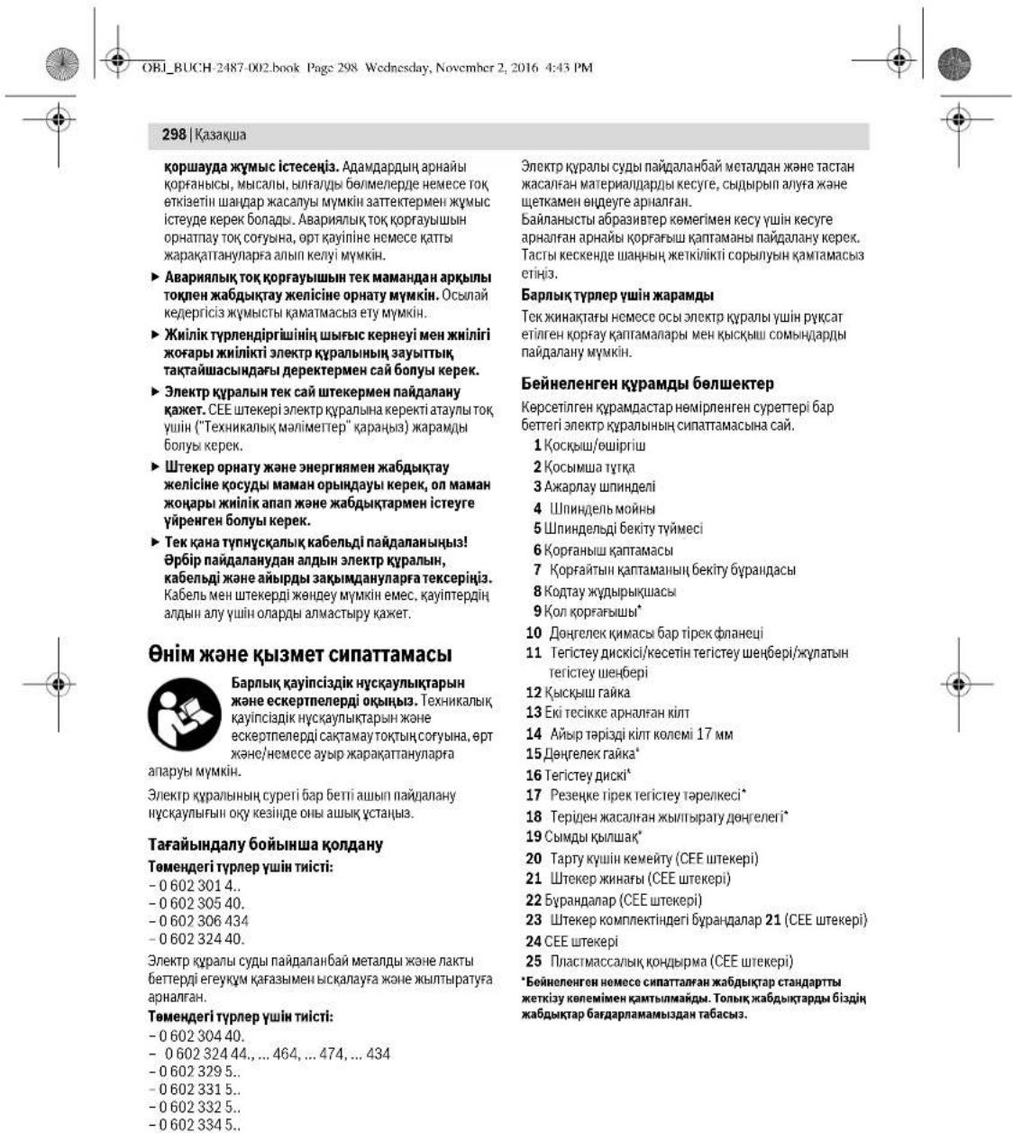
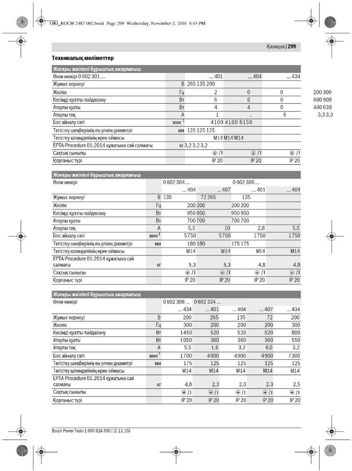
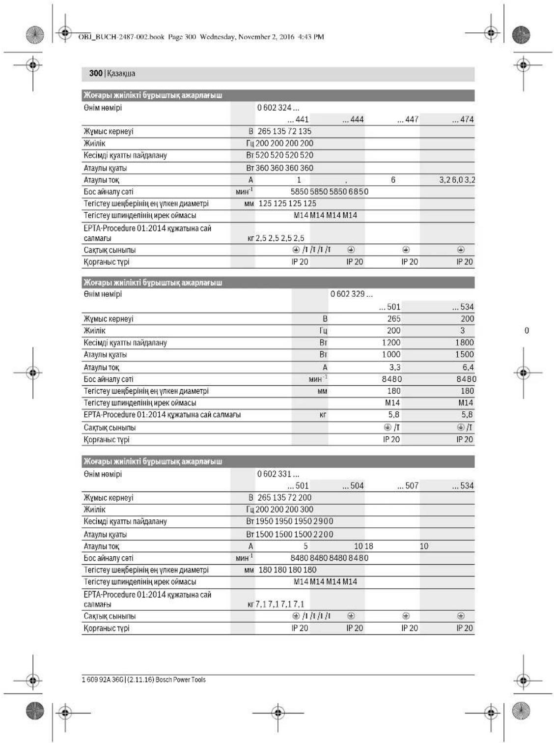
Kazakhstan 301
| Жогары жинникovi Бурштейх онлайнарлайы | |||||
| Одир | 0 602 332 ... | ||||
| ... 501 | ... 504 | ... 507 | ... 534 | ... 511 | |
| Жу mus керneyi | В 265 135 72 200 72 | ||||
| Жилік | ГИ 200 200 200 300 300 | ||||
| Кесimлі куаты падалану | Вt 1950 1950 1950 2900 2900 | ||||
| Атыны куаты | Вt 1500 1500 1500 2200 2200 | ||||
| Атыны тok | A 5 | 10 18 10 27 | |||
| Бос сөнүлү сati | MH1 | 6600 6600 6600 6600 6600 | |||
| Тerитreyшисторийен улковен даметri | MM 230 230 230 230 230 | ||||
| Тerитreyшисторийен рек омамсь | M14 M14 M14 M14 M14 | ||||
| EPTA-Procedure 01:2014 куатыни сай салmarы | Кr 7,1 7,1 7,1 7,1 | ||||
| Сасктikсынгліп | ⊕ /I | ⊕ /I | ⊕ /I | ⊕ /I | ⊕ /I |
| Корганьс typi | IP 20 | IP 20 | IP 20 | IP 20 | IP 20 |
| Жогары жинлікі 6урьшіх ожарліш | |||||
| Бим Номіп | 0.602 334 ... | ||||
| ...501 | ...504 | ...507 | ...534 | ||
| Жуmbіс керneyі | В | 265 | 135 | 72 | 200 |
| Жиінік | Гц | 200 | 200 | 200 | 300 |
| Kecimidi Ка {@гійсянійядану | Вт | 2500 | 2500 | 2500 | 3800 |
| Атылы К {@гійь | Вт | 2200 | 2200 | 2200 | 3100 |
| Атылы тok | A | 6,7 | 13,2 | 24,7 | 13,2 |
| Бос {@йдану сati | MHN¹ | 6600 | 6600 | 6600 | 6600 |
| TerICTY {@йдану сенин {@йдану діаметri | MM | 230 | 230 | 230 | 230 |
| TerICTY {@йдану діенин {@йдану діаметri | M14 | M14 | M14 | M14 | M14 |
| EPTA-Procedure 01:2014 К {@йдану сад canмafы | Кт | 7,8 | 7,8 | 7,8 | 7,8 |
| Са {@йдану сад canмafы | © /1 | © /1 | © /1 | © /1 | © /1 |
| Кор? Кор? Кор? Кор? Кор? Кор? Кор? Кор? Кор? Кор? Кор? Кор? Кор? Кор? Кор? Кор? Кор? Кор? Кор? Кор? Кор? Кор? Кор? Кор? Кор? Кор? Кор? Кор? Кор? Кор? Кор? Кор? Кор? Кор? Kор? Kор? Kор? Kор? Kор? Kор? Kор? Kор? Kор? Kор? Kор? Kор? Kор? Kор? Kор? Kор? Kор? Kор? Kор? Kор? Kор? Kор? Kор? Kор? Kор? Kор? Kор? Kор? Kор? Kор? Kор? Kор? Kор? Kor? Kor? Kor? Kor? Kor? Kor? Kor? Kor? Kor? Kor? Kor? Kor? Kor? Kor? Kor? Kor? Kor? Kor? Kor? Kor? Kor? Kor? Kor? Kor? Kor? Kor? Kor? Kor? Kor? Kor? Kor? Kor? Kor? Kor? Кor? Kor? Kor? Kor? Kor? Kor? Kor? Kor? Kor? Kor? Kor? Kor? Kor? Kor? Kor? Kor? Kor? Kor? Kor? Kor? Kor? Kor? Kor? Kor? Kor? Kor? Kor? Kor? Kor? Kor? Kor? Kor? Kor? KOR? Kor? Kor? Kor? Kor? Kor? Kor? Kor? Kor? Kor? Kor? Kor? Kor? Kor? Kor? Kor? Kor? Kor? Kor? Kor? Kor? Kor? Kor? Kor? Kor? Kor? Kor? Kor? Kor? Kor? Kor? Kor? Kor? Kor? Kor? Kor? Kor? Kor? Kor? Kor? Kor? Kor? Kor? Kor? Kor? Kor? Kor? Kor? Kor? Kor? Kor? Kor? Kor? Kor? Kor? Kor? Kor? Kor? Kor? Kor? Kor? Kor? Kor? Kor? Kor? Kor? Kor? Кor? Kor? Kor? Kor? Kor? Kor? Kor? Kor? Kor? Kor? Kor? Kor? Kor? Kor? Kor? Kor? Kor? Kor? Kor? Kor? Kor? Kor? Kor? Kor? Kor? Kor? Kor? Kor? Kor? Kor? Kor? Kor? Kor? Кор? Kor? Kor? Kor? Kor? Kor? Kor? Kor? Kor? Kor? Kor? Kor? Kor? Kor? Kor? Kor? Kor? Kor? Kor? Kor? Kor? Kor? Kor? Kor? Kor? Kor? Kor? Kor? Kor? Kor? Kor? Kor? Kor? Kor; Kor? Kor? Kor? Kor? Kor? Kor? Kor? Kor? Kor? Kor? Kor? Kor? Kor? Kor? Kor? Kor? Kor? Kor? Kor? Kor? Kor? Kor? Kor? Kor? Kor? Kor? Kor? Kor? Kor? Kor? Kor? Kor? Kor? .Kor? Kor? Kor? Kor? Kor? Kor? Kor? Kor? Kor? Kor? Kor? Kor? Kor? Kor? Kor? Kor? Kor? Kor? Kor? Kor? Kor? Kor? Kor? Kor? Kor? Kor? Kor? Kor? Kor? Kor? Kor? Kor? Kor? Ker? Ker? Ker? Ker? Ker? Ker? Ker? Ker? Ker? Ker? Ker? Ker? Ker? Ker? Ker? Ker? Ker? Ker? Ker? Ker? Ker? Ker? Ker? Ker? Ker? Ker? Ker? Ker? Ker? Ker? Ker? Ker? Ker? Ker? Ker? Ker? Ker? Ker? Ker? Ker? Ker? Ker? Ker? Ker? Ker? Ker? Ker? Ker? Ker? Ker? Ker? Ker? Ker? Ker? Ker? Ker? Ker? Ker? Ker? Ker? Ker? Ker? Ker? Ker? Ker? Ker? Ker? KER? Ker? Ker? Ker? Ker? Ker? Ker? Ker? Ker? Ker? Ker? Ker? Ker? Ker? Ker? Ker? Ker? Ker? Ker? Ker? Ker? Ker? Ker? Ker? Ker? Ker? Ker? Ker? Ker? Ker? Ker? Ker? Ker? Ker. Ker? Ker? Ker? Ker? Ker? Ker? Ker? Ker? Ker? Ker? Ker? Ker? Ker? Ker? Ker? Ker? Ker? Ker? Ker? Ker? Ker? Ker? Ker? Ker? Ker? Ker? Ker? Ker? Ker? Ker? Ker? Ker? Ker? Кer? Ker? Ker? Ker? Ker? Ker? Ker? Ker? Ker? Ker? Ker? Ker? Ker? Ker? Ker? Ker? Ker? Ker? Ker? Ker? Ker? Ker? Ker? Ker? Ker? Ker? Ker? Ker? Ker? Ker? Ker? Ker? Ker? K. Ker? Ker? Ker? Ker? Ker? Ker? Ker? Ker? Ker? Ker? Ker? Ker? Ker? Ker? Ker? Ker? Ker? Ker? Ker? Ker? Ker? Ker? Ker? Ker? Ker? Ker? Ker? Ker? Ker? Ker? Ker? Ker? Ker; Ker? Ker? Ker? Ker? Ker? Ker? Ker? Ker? Ker? Ker? Ker? Ker? Ker? Ker? Ker? Ker? Ker? Ker? Ker? Ker? Ker? Ker? Ker? Ker? Ker? Ker? Ker? Ker? Ker? Ker? Ker? Ker? Ker? Liz. Liz. Liz. Liz. Liz. Liz. Liz. Liz. Liz. Liz. Liz. Liz. Liz. Liz. Liz. Liz. Liz. Liz. Liz. Liz. Liz. Liz. Liz. Liz Liz Liz Liz Liz Liz Liz Liz Liz Liz Liz Liz Liz Liz Liz Liz Liz Liz Liz Liz Liz Liz Liz Liz Liz Liz Liz Liz Liz Liz Liz Liz Liz Liz (Liz) Liz Liz Liz Liz Liz Liz Liz Liz Liz Liz Liz Liz Liz Liz Liz Liz Liz Liz Liz Liz Liz Liz Liz Liz Liz Liz Liz Liz Liz Liz Liz Liz Liz . Liz Liz Liz Liz Liz Liz Liz Liz Liz Liz Liz Liz Liz Liz Liz Liz Liz Liz Liz Liz Liz Liz Liz Liz Liz Liz Liz Liz Liz Liz Liz Liz Liz | |||||
Safety instructions for all operations
The rotary hammer must be checked for correct operation before each use. Check that the drill bit is securely locked in the tool holder.
For this work, the rotary hammer must be inserted into the tool holder (see "Inserting the drill bit", page 306).
Switching on and off
This power tool complies with EN 60745-2-6.
| 060230140. | 0602301434. | 060230440. | 060230540. | |
| А-menбеленгэн злескт куралын | \( \begin{array}{c} \\ {\text{Дыбс куш рдпг}}\end{array} \) | \( \begin{array}{c} \\ {\text{Дыбс куш рдпг}}\end{array} \) | \( \begin{array}{c} \\ {\text{Дыбс куш рдпг}}\end{array} \) | \( \begin{array}{c} \\ {\text{Дыбс куш рдпг}}\end{array} \) |
| Богау | \( \begin{array}{c} \\ {\text{Дыбс куш рдпг}}\end{array} \) | \( \begin{array}{c} \\ {\text{Дыбс куш рдпг}}\end{array} \) | \( \begin{array}{c} \\ {\text{Дыбс куш рдпг}}\end{array} \) | \( \left.\begin{array}{l}\text{76}\\87\\3\end{array}\right. \) |
| Богау | \( \begin{array}{c} \\ {\text{Дыбс куш рдпг}}\end{array} \) | \( \begin{array}{c} \\ {\text{Дыбс куш рдпг}}\end{array} \) | \( \begin{array}{c} \\ {\text{Дыбс куш рдпг}}\right. \) | \( \begin{array}{c} \\ {\text{76}}\\ {87}\\ {3\end{array} \) |
| Богау | \( \begin{array}{c} \\ {\text{Дыбс куш рдпг}}\end{array} \) | \( \begin{array}{c} \\ {\text{Дыбс куш рдпг}}\end{array} \) | \( \begin{array}{c} \\ {\text{Дыбс куш р徴}}\end{array} \) | \( \begin{array}{c} \\ {\text{76}}\\ {87}\\ {3\end{array} \) |
| Богау | \( \begin{array}{c} \\ {\text{Дыбс куш р徴}}\end{array} \) | \( \begin{array}{c} \\ {\text{Дыбс куш р徴}}\end{array} \) | \( \begin{array}{c} \\ {\text{Дыбс куш р徴}}\end{array} \) | \( \begin{array}{c} \\ {\text{76}}\\ {87}\\ {3\end{array} \) |
| Богау | \( \begin{array}{c} \\ {\text{Дыбс куш р徴 }}\end{array} \) | \( \begin{array}{c} \\ {\text{Дыбс куш р徴}}\end{array} \) | \( \begin{array}{c} \\ {\text{Дыбс куш р徴}}\end{array} \) | \( \begin{array}{c} \\ {\text{76}}\\ {87}\\ {3\end{array} \) \( \begin{array}{c} \\ {\text{Дыбс куш р徴 }}\end{array} \) |
| Богау | \( \begin{array}{c} \\ {\text{Дыбс куш р徴 }}\end{array} \) | \( \begin{array}{c} \\ {\text{Дыбс куш р徴 }}\end{array} \) | \( \begin{array}{c} \\ {\text{Дыбс куш р徴 }}\end{array} \) | \( \begin{array}{c} \\ {\text{Дыбс куш р徴 }}\end{array} \) |
Bosch Power Tools 1609 92A 36C (2.11.16)


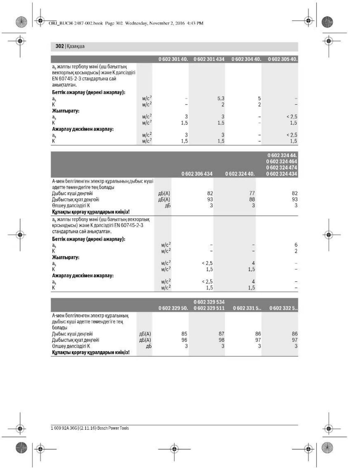


| 0.60232950. | 0.6023295340.602329511 | 0.6023315.. | 0.6023325.. | |
| a₁ kānilbī Čeρбěny māni (vú 6aβhɪtbiŋBékθoplýk κούbɪdciú) xáne K dānciádiRiEN 60745-2-3 stándeptbɪha cai aHbɪkʌtɪgən. | ||||
| Bettik Āxapnay (népeki Āxapnay): | ||||
| a₁ | M/c² | 7 | 7 | 7 |
| K | M/c² | 1,5 | 1,5 | 1,5 |
| Жыntьрату: | ||||
| a₁ | M/c² | - | - | - |
| K | M/c² | - | - | - |
| Aşxpapnay дсхимен Āxapnay: | ||||
| a₁ | M/c² | - | - | - |
| K | M/c² | - | - | - |
Henk Becker Executive Vice President Engineering
Helmut Heinzelmann Head of Product Certification PT/ECS
IV. h = mc
Robert Bosch Power Tools GmbH 70538 Stuttgart, GERMANY Stuttgart, 01.01.2017

OBI_BUCH-2487-002.book Page 304 Wednesday, November 2, 2016 4:43 PM
304|Kasaika
XnHay
KopfahbIw Ka6bIKTapbH opHaty
Kannbi HcyckaynbikTap
KabknappeTey,6nueKepinAnmaCTbpy Hemece3NtKpKaanBhAkbpatyDahAnbH ToTKAH bifapbH.ObcCaTbIlaPacbaNtKpKaanBbH BaKayCbIaKocunByHaKoBgeMeH
Eckptne:Kc3HcTeTcrtey H6epi 63bna Hmece Kopr4aBn KaTnAa3Nekr KpAa KpBnBnAp 63bna,3NkPr KpAanBbipDcpeh CepBn K3MeTine X6epy Kepe, MekeHKnAaRnTyBtBuHaKa3MeTkepeTyXeH naidanany KeheCteP rapayBnH Kapab.
Koparbiu kantamapanably uykbladabapabln onepatop xafiba Kaapan yuanahtbaid etin opahtBu3h.
Excerpt: KoprAflblu KaTAMamabHb KOnrTaY KjduBpUkwnapBc TeK 3neKT KpAnra JkaPaTbHn KoprAflb KaTAMahBb OPhATyDb KMaTAmacBc3 etEdi.
Tericteyre aphanfah Koprafbkantama (A cypetih kapaht)
Tomehderi typep yiwin thicti:
-060230440. -06023295.. -0602324434 -06023315.. -060232444. -06023325.. -0602324464 -06023345.. -0602324474 KoprarbKaTAMAH6apHaiXkayr7emEHH8 Kemerim HINHNBb MOHnHDAfb 4OikkaKoprAaH KaTAMadafbybypTH3eKTPKypandbHpnaHeJine OtbpaHuaOpahtsbH. Kmbic npocciHtanaTapbHa cai Kopfarbl KaTamaHbH KyHH CaKaTaHb3. -Kopfanshi kantamahbi 6ketyi yuih onyatny BHITH 7 10HM acnathai aihanyap Myomehitant Tahtb3h.
KoBmIaY TynkipDnye KEM KonaiyIbXyMbC IcTeReY MvKnIKD6bpN.

3Neektp KpyanbHbI3bI TeK KobimMa TytKa 2MeHen naiDananbHbI3. -KocbIMUa TYKahB 2peyKOpbnBk6bA3hOn OHJXHnHaD HEMeC on KxHnHaB bypan 6ekTjHs. dbimwaaTytkahbIe3reptneH3. 3aKbIMdaFAnKocbIMwa TYTKaHbI naIaNanHa6aHbI.
Temperature type and time:

Qualification of the operator: The operator must have at least 11 (eleven) years of education (secondary education, specialized secondary education, higher education) and have undergone appropriate training. - When operating the device, it is necessary to follow the instructions given in the operating manual. When operating the device, it is necessary to strictly follow the instructions given in section 14 of this manual.
Operation
- The device must be operated by at least 3 (three) people.
- Before operating the device, it is necessary to read section 13 carefully, and then section 14 of this manual.
- Check the device, if it is in good condition
- Check the device.
Electric shock hazard: disconnect the power supply
Temperature type and time:
-060232440 -0602324434 -060232444
Disconnect the power supply before performing any work on the electric circuit. The device must be disconnected from the mains (by turning off the circuit breakers E1-E2).
The device must not be operated without the protective cover. It is possible to connect the electric circuit.
- To connect the device to the power supply, it is necessary to use a power supply with a protective earth conductor. - The device must be connected to the mains (see section 304 of the operating manual, the specialized operating manual, or the operating manual of the device) - Before connecting the device to the power supply, check the protective earth conductor.
Read the text before installation (see Figure 1).
The following types of pipes:
-06023014. -060232440 -060230540. -0602306434
Installation diagram
- The number of connecting pipes for the installation of the original technical means (see Figure 2, page 304).
- Read the text before installation 17 times, 3 times for each of the 3 original texts. The text is given in 16 sections before installation. -Refer to the 15th section for the relevant information. Install it.
- The installation diagram shows 13 sections, and the 14th section is installed with 3 dry pipes.
Kazakh 305
The installation diagram shows 15 sections before installation. The installation procedure is carried out in accordance with the installation rules and the installation rights are granted only to the original manufacturer.
Selection
The installation is carried out with 3 dry pipes in 14 sections. -The 15th section is installed with 13 components and the installation is carried out. The installation procedure is described in the installation diagram.
Material selection procedure (see Figure 2)
The following types of pipes:
306|Kazakh
Read the instruction manual carefully before using the device. Keep the manual for future reference. Use the device only for its intended purpose, as described in the manual. Failure to follow the instructions may result in damage to the device or injury.
Corrosive substances, acids, solvents, minerals, and metals can damage all types of materials. It is possible to cause chemical reactions or other harmful effects if they come into contact with the device. Some materials, especially those that are flammable, explosive, or contain hazardous components (such as chromates, asbestos, or lead-based paints), may be carcinogenic. Handle such materials with extreme caution.
- The user is responsible for the safe disposal of this material. Consult the local regulations for proper disposal.
- The device should be installed in a location that is not exposed to direct sunlight or moisture.
The device should be used only with the materials specified in the instructions.
Do not operate the device without proper ventilation. Keep the area around the device clear.
Power connection
The power cord must be connected to a properly grounded outlet. Do not use an extension cord unless it is absolutely necessary.
When using the device, keep it away from water, heat sources, and direct sunlight. Do not touch the power cord with wet hands. Ensure that the power cord is not damaged.
The power cord must be connected to a suitable power source. If the cord is damaged, it must be replaced by the manufacturer or a qualified technician.
The device must be connected to a power supply that meets the specifications in the technical data. If the power supply is not suitable, the device may be damaged. Consult the technical data for the correct power supply.
Do not use the device if the power cord or plug is damaged. Contact a qualified technician for repairs.
See the connection diagram (Figures I1-I2).
- Remove the cover of the 21-pin connector of the 24-pin housing. Connect the 25-pin connector of the cable to the 21-pin connector of the housing. The device is ready for operation after 20 minutes.
Remove the cover of the 23-pin connector of the 21-pin housing. Connect the cable to the L1 contact of the device.
Connect the L2 contact of the device to the L2 contact of the L3 contact of the device. Connect the L3 contact of the device to the L3 contact of the device. Connect the cable to the 21-pin connector of the 23-pin housing. The device is ready for operation after 20 minutes. - Connect the 21-pin connector of the 24-pin housing to the 22-pin connector of the device. The device is ready for operation. - Connect the 21-pin connector of the 24-pin housing to the 22-pin connector of the device.
The device is ready for operation.
The device is ready for operation.
The device is ready for operation.
The device is ready for operation.
The device is ready for operation.
If the device is not working, check the power supply and the fuse.
Remove the cover of the 22-pin connector of the 21-pin housing. Connect the 21-pin connector of the 24-pin housing to the 22-pin connector of the device. - Connect the L1 contact of the device to the L1 contact of the device. - Connect the L2 contact of the device to the L2 contact of the device. - Connect the L3 contact of the device to the L3 contact of the device. - Connect the 21-pin connector of the 24-pin housing to the 22-pin connector of the device. - The device is ready for operation.
Operation
Operation
The device must be operated with the correct voltage and frequency. The device is ready for operation. The device is ready for operation.
160992A36G|(2.11.16) Bosch Power Tools






OBI_BUCH-2487-002.book Page 307 Wednesday, November 2, 2016 4:43 PM
The disconnection of the electrical network is carried out by disconnecting the circuit breakers. Before disconnecting the circuit breakers, the load must be removed.
The circuit breaker "Koshyu" type is used for switching electrical networks. The circuit breaker "Koshyu" is designed for 60 kV. The circuit breaker's disconnection ("Energy release" 306 V) is carried out by the energy storage device.
The electrical network is disconnected only by the circuit breaker.
Types of circuit breakers
For alternating current, two circuit breakers are used, and the electrical network must be disconnected.
The circuit breaker is not designed for frequent switching.
Disconnecting the electrical network - Safety instructions (see Figure 1)
For the following types:
-06023244
- For disconnecting the electrical network, press the circuit breaker button 1. - To reset the circuit breaker, press the circuit breaker button 1 again. - The circuit breaker is not designed for frequent switching.
Before resetting the circuit breaker, press the button 1 and hold it for a few seconds.
Disconnecting the electrical network - Safety instructions (see Figure 2)
For the following types:
Electrical safety instructions for the use of household appliances, as well as for their maintenance.
- Before using the appliance, read the safety instructions and the operating manual carefully. The electrical appliance is intended only for household use, and for use in accordance with the operating instructions.
Safety warnings
To avoid the risk of electric shock, do not immerse the appliance, cord, or plug in water or other liquids. If the appliance falls into water, unplug it immediately. Do not reach into the water. Do not use the appliance near bathtubs, showers, or swimming pools. Do not use the appliance with wet hands. Do not use the appliance outdoors.
To avoid the risk of fire, do not use the appliance near flammable materials or liquids.
Before cleaning, unplug the appliance.
Before cleaning, unplug the appliance and allow it to cool down completely.
Before cleaning, unplug the appliance and allow it to cool down completely. Do not immerse the appliance in water or any other liquid.
Maintenance (Cleaning)
Before cleaning, unplug the appliance and allow it to cool down completely.
Clean the appliance with a soft, dry cloth. Do not use abrasive cleaners or solvents. Do not immerse the appliance in water or any other liquid.
The appliance must be stored in a dry place. Do not store it near heat sources or in direct sunlight.
Do not use the appliance if the cord or plug is damaged. Contact a qualified service center for repair.
Storage
This device is intended for cutting and grinding. Read the instructions before use. This power tool is designed for cutting/grinding work only.
Do not use the cutting disc for grinding. The manufacturer's instructions must be followed. Use only accessories that are approved for this power tool.
The power tool must be used with the guard supplied with the tool. The guard must be correctly fitted and adjusted. Do not use the power tool without the guard. When using the power tool, always wear protective equipment.
The guard protects the operator from broken wheel fragments and accidental contact with the grinding wheel. The guard must be adjusted so that the maximum amount of wheel is exposed. The guard must be positioned so that sparks and debris are directed away from the operator.
The power tool must be used only with the accessories specified in these instructions. Do not use accessories that are not recommended by the manufacturer. The use of inappropriate accessories can cause injury.




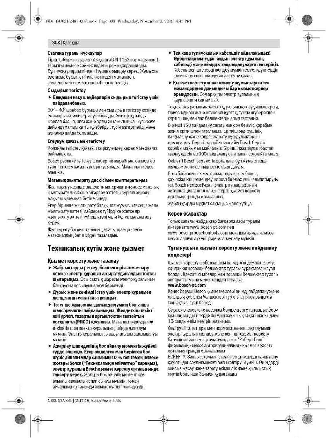
310 Romania
OB BUCH-2487-012 hook Page 311 Wednesday, November 2, 2016 4:43 PM
Romania|311
Electric tools must not be used with abrasive wheels unless they are specifically designed for that purpose. Using an electric tool not designed for this purpose can cause dangerous situations and bodily injury. Common safety warnings for grinding, sanding, wire brushing, polishing, and cutting operations: Do not use accessories that are not specifically designed and recommended by the tool manufacturer. The fact that an accessory can be attached to your electric tool does not guarantee safe operation. The rated speed of the accessory must be at least equal to the maximum speed marked on the electric tool. Accessories running faster than their rated speed can fly apart and cause injury. The outside diameter and thickness of your accessory must be within the capacity rating of your electric tool. Incorrectly sized accessories cannot be adequately guarded or controlled. The arbor size of wheels, flanges, backing pads, or any other accessory must properly fit the spindle of the electric tool. Accessories with arbor holes that do not match the mounting hardware of the electric tool will run out of balance, vibrate excessively, and may cause loss of control. Do not use damaged accessories. Before each use, inspect the accessory such as abrasive wheels for chips and cracks, backing pad for cracks, tear or excess wear, and wire brush for loose or cracked wires. If the electric tool or accessory is dropped, inspect for damage or install an undamaged accessory. After inspecting and installing an accessory, position yourself and bystanders away from the plane of the rotating accessory and run the electric tool at maximum no-load speed for one minute. Damaged accessories will normally break apart during this test time. Wear personal protective equipment. Depending on application, use face shield, safety goggles or safety glasses. As appropriate, wear dust mask, hearing protectors, gloves and workshop apron capable of stopping small abrasive or workpiece fragments. The eye protection must be capable of stopping flying debris generated by various operations. The dust mask or respirator must be capable of filtrating particles generated by your operation. Prolonged exposure to high intensity noise may cause hearing loss. Keep bystanders a safe distance away from work area. Anyone entering the work area must wear personal protective equipment. Fragments of workpiece or of a broken accessory may fly away and cause injury beyond immediate area of operation. Hold the power tool by insulated gripping surfaces only, when performing an operation where the cutting accessory may contact hidden wiring or its own cord. Cutting accessory contacting a "live" wire may make exposed metal parts of the power tool "live" and could give the operator an electric shock. Position the cord clear of the spinning accessory. If you lose control, the cord may be cut or snagged and your hand or arm may be pulled into the spinning accessory. Never lay the power tool down until the accessory has come to a complete stop. The spinning accessory may grab the surface and pull the power tool out of your control. Do not run the power tool while carrying it at your side. Accidental contact with the spinning accessory could snag your clothing, pulling the accessory into your body. Regularly clean the power tool's air vents. The motor's fan will draw the dust inside the housing and excessive accumulation of powdered metal may cause electrical hazards. Do not operate the power tool near flammable materials. Sparks could ignite these materials. Do not use accessories that require liquid coolants. Using water or other liquid coolants may result in electrocution or shock.
Before using the tool, ensure that the work area is clear of any obstructions. Always wear appropriate personal protective equipment. Do not use the tool in damp or wet conditions. Keep the tool away from children and untrained persons. Do not force the tool; use it at the rate for which it was designed. Use the correct tool for your application. The correct tool will do the job better and safer at the rate for which it was designed. Do not use the tool if the switch does not turn it on and off. Any tool that cannot be controlled with the switch is dangerous and must be repaired. Disconnect the plug from the power source and/or the battery pack from the tool before making any adjustments, changing accessories, or storing power tools. Such preventive safety measures reduce the risk of starting the tool accidentally. Store idle power tools out of the reach of children and do not allow persons unfamiliar with the power tool or these instructions to operate the power tool. Power tools are dangerous in the hands of untrained users. Maintain power tools. Check for misalignment or binding of moving parts, breakage of parts and any other condition that may affect the power tool's operation. If damaged, have the power tool repaired before use. Many accidents are caused by poorly maintained tools. Keep cutting tools sharp and clean. Properly maintained cutting tools with sharp cutting edges are less likely to bind and are easier to control. Use the power tool, accessories and tool bits etc., in accordance with these instructions, taking into account the working conditions and the work to be performed. Use of the power tool for operations different from those intended could result in a hazardous situation.
Always keep the power tool away from rotating accessories. If you lose control, the power cord may be cut or snagged, and your hand or arm may be pulled into the rotating accessory. Never place your hand near the rotating accessory while the tool is in operation. The accessory may kick back over your hand. If the accessory becomes pinched or snagged, the reaction torque of the motor may cause the tool to twist. Always use the auxiliary handle, if provided, to maintain control. If the accessory binds, the tool may suddenly jerk in the opposite direction of the accessory's rotation. This can cause loss of control and serious injury. Do not use the tool near flammable materials. Sparks from the motor may ignite dust or fumes. Keep the power cord away from the rotating accessory. If you lose control, the cord may be cut and you may receive an electric shock. Do not use the tool in damp or wet conditions. Moisture can cause electric shock. Keep the tool clean and free of dust and debris. Accumulated metal dust can cause electric shock. Do not use the tool in areas where there is a risk of explosion. Sparks may ignite flammable liquids, gases, or dust.
312 Romanian
of kickback or reaction torque at high speeds. The operator can control kickback and reaction forces by taking proper precautions.
324|Bulgarian
The Bosch consulting team will be happy to answer any questions you may have about our products and their accessories.
For complaints and spare parts orders, please always indicate the identification number consisting of
Tel. power tool service: (021) 4057540
Fax: (021) 4057566
E-Mail: infoBSC@ro.bosch.com
Tel. customer consulting: (021) 4057500
Fax: (021) 2331313
E-Mail: infoBSC@ro.bosch.com
www.bosch-romania.ro
Disposal
Power tools, accessories and packaging should be directed to an ecological recycling station.
Do not throw power tools into household waste!
Safety when working with electric tools
The power tool must be suitable for the intended use. In any case, do not allow children or unauthorized persons to use it. When working with electric tools, never use the tool without the guard. The use of the tool for purposes other than those intended may result in electric shock. Avoid touching grounded surfaces, such as pipes, radiators, ranges and refrigerators. When your body is grounded, the risk of electric shock is increased. Do not expose power tools to rain or wet conditions. Water entering a power tool will increase the risk of electric shock. Do not abuse the cord. Never use the cord for carrying, pulling or unplugging the power tool. Keep cord away from heat, oil, sharp edges or moving parts. Damaged or entangled cords increase the risk of electric shock. When operating a power tool outdoors, use an extension cord suitable for outdoor use. Use of a cord suitable for outdoor use reduces the risk of electric shock. If operating a power tool in a damp location is unavoidable, use a residual current device (RCD) protected supply. Use of an RCD reduces the risk of electric shock.
Safe working practices
Stay alert, watch what you are doing and use common sense when operating a power tool. Do not use a power tool while you are tired or under the influence of drugs, alcohol or medication. A moment of inattention while operating power tools may result in serious personal injury. Use personal protective equipment. Always wear eye protection. Protective equipment such as dust mask, non-skid safety shoes, hard hat, or hearing protection used for appropriate conditions will reduce personal injuries. Prevent unintentional starting. Ensure the switch is in the off-position before connecting to power source and/or battery pack, picking up or carrying the tool. Carrying power tools with your finger on the switch or energising power tools that have the switch on invites accidents.


The battery charger is a safety device. It must be kept away from moisture. If, while wearing the electronic device, you feel chest pain, or if the charger is damaged and the electronic device is turned on, there is a danger of a serious electric shock.
Before turning on the power tool, make sure it is not in contact with any part of your body or with other tools or keys. A tool that is switched on and held by the handle can cause injury. Avoid unnatural postures and keep your balance at all times. This way you can better control the power tool in unexpected situations. Work calmly and carefully. Do not work with loose clothing or jewelry. Keep your hair away from the tool and maintain a safe distance from the rotating parts. The rotating parts of the tool can catch loose clothing or jewelry and pull them in. If a dust extraction system is available, make sure it is connected and functioning properly. Using a dust extraction system can reduce dust-related hazards.
Careful handling and use of power tools
Do not overload the power tool. Use the power tool only for its intended purpose. Work properly and safely, using the appropriate power tool for the task. Do not use the power tool if the switch does not turn it on and off. A power tool that cannot be controlled with the switch is dangerous and must be repaired. Before adjusting, changing accessories, or storing the power tool, disconnect it from the power source and remove the battery pack. This precaution reduces the risk of accidental starting. Store power tools out of the reach of children and do not allow people who are not familiar with the instructions to use them. Power tools are dangerous in the hands of untrained users. Maintain power tools. Check for misalignment or binding of moving parts, breakage of parts, and any other condition that may affect the operation of the power tool. If damaged, have the power tool repaired before use. Many accidents are caused by poorly maintained power tools.
Keep cutting tools sharp and clean. Properly maintained cutting tools with sharp cutting edges are less likely to bind and are easier to control. Use the power tool, accessories, and bits, etc., in accordance with these instructions, taking into account the working conditions and the work to be performed. Use of the power tool for operations different from those intended could result in a hazardous situation.
Repair and maintenance of power tools must only be carried out by qualified personnel using original spare parts. This will ensure that the safety of the power tool is maintained. When using power tools, always follow the safety instructions and the operating conditions required for the work. Using power tools for purposes other than those intended can lead to dangerous situations.
Maintenance
Allow only qualified personnel to repair the power tool, and only with original spare parts. This will ensure that the safety of the power tool is maintained.
Safety instructions for the use of the tool with the appropriate safety instructions for the use of the tool when working with the tool
The following models are affected:
332|Bulgarian
| Ви这样做�能帮您打赢仗吗 | ||||
| Каталожен Homep | 0 602 334 ... | |||
| ...501 | ...504 | ...507 | ...534 | |
| HommaHann HappekeHne | V 265 135 72 200 | |||
| Yectota | Hz 200 200 200 300 | |||
| HommaHann KonsmmpaHa Mochnoct | W 2500 2500 2500 3800 | |||
| HommaHann NopesHa Mochnoct | W 2200 2200 2200 3100 | |||
| HommaHann ToK | A 6 | . | 7 | 13,2 24,7 13,2 |
| Скорост на Вьтende на праzenхоД | min-1 | 6600 6600 6600 6600 | ||
| Масдиметер нашифовачи дск | mm 230 230 230 230 | |||
| Рezба на вала | M14 M14 M14 M14 | |||
| Мас сглесно EPTA-Procedure 01:2014 -绛з симогателна рыковатka | kg7,87,87,87,8 | |||
| Клас на зашипа | + /T | + /T | + /T | + /T |
| Вidдацilla | IP 20 | IP 20 | IP 20 | IP 20 |
Safety instructions for disposal
Power tools operate at high frequency and require a separate power supply with a transformer according to the instructions and the accessory.
In case of malfunction, the power tool must be connected to the mains via a residual current device (see connection to the power supply), page 336).
The vibration values have been determined in accordance with EN 60745-2-3.
Declared vibration emission value
| 0.60230140. | 0.602301434 | 0.60230440. | 0.60230540. | |
| Равишиeto I Ha Ильчваима ум обикно- вениe | ||||
| Равишиeto Ha зуковою налгане | dB(A) | 72 | 82 | 79 |
| Мошост Ha зува | dB(A) | 83 | 93 | 90 |
| НошpeденистК | dB | 3 | 3 | 3 |
| РавOTe creшуоагн'te: | ||||
| Пьіната стейност Ha Вибрацпiteæ (be- Ктосята сума по Трипе налары成为一名 ношpeденистК са оретени К. trал scho EN 60745-2-3. | ||||
| Шифobaning(rpy6ошнфobaninge): | ||||
| a₁ | m/s² | - | 5,3 | 5 |
| K | m/s² | - | 2 | 2 |
| Полиганe: | ||||
| a₁ | m/s² | 3 | 3 | - |
| K | m/s² | 1,5 | 1,5 | 1,5 |
| Шифobaninge сшкypka: | ||||
| a₁ | m/s² | 3 | 3 | - |
| K | m/s² | 1,5 | 1,5 | 1,5 |
Bulgarian|333
Henk Becker Helmut Heinzelmann Executive Vice President Head of Product Certification Engineering PT/ECS

Robert Bosch Power Tools GmbH 70538 Stuttgart, GERMANY Stuttgart. 01.01.2017
WARNING: To reduce the risk of injury, user must read instruction manual.
General Power Tool Safety Warnings
Read all safety warnings and all instructions. Failure to follow the warnings and instructions may result in electric shock, fire and/or serious injury. Save all warnings and instructions for future reference.
WARNING: When using power tools, basic precautions should always be followed to reduce the risk of fire, electric shock, and personal injury, including the following.
Read all instructions before using the product. If the power tool is damaged or not working properly, it must be repaired by an authorized service center. For service, contact the nearest Bosch service center.
The original accessories are designed for use with this power tool. Using other accessories may result in injury.
WARNING: The power tool is intended for professional use. Do not modify the power tool or use it for purposes other than those intended.
Replacing the dust bag (see figure A)
This is for the following models:
- 060230440. - 06023295.. - 0602324434 - 06023315.. - 060232444. - 06023325.. - 0602324464 - 06023345..
- 0602324474
Place the dust bag with the collar onto the dust outlet or the adapter, until the dust bag is firmly attached to the power tool. - Adjust the dust bag to the working conditions. - To empty the dust bag, open the zipper and empty it. Do not use the dust bag without the filter.
Replacing the dust bag for cutting
This section applies to the following models:
-060230440. -06023295.. -0602324434 -06023315.. -060232444. -06023325.. -0602324464 -06023345.. -0602324474
For mounting the cutting blade, use the supplied blade guard. The guard is made of metal and is intended to protect the operator from the blade. (It is not included in the standard delivery.)
The blade guard for cutting must be mounted correctly and in accordance with the standard blade guard (see figure A).
The auxiliary handle must be mounted (see figure B).
The auxiliary handle is mounted on the front part of the tool in the clamping area and is secured by tightening. Use the power tool only with the auxiliary handle mounted. The auxiliary handle can be adjusted according to the working method and the direction of the tool. In no case should you attempt to modify the auxiliary handle in any way. Do not use the auxiliary handle if it is damaged.



OBI_BUCH-2487-002.book Page 335 Wednesday, November 2, 2016 4:43 PM
Bulgarian | 335
Cutting guard (see figure C)
This section applies to the following models:
-06023014. -060232440 -060230540. -0602306434
When working with a depressed center grinding wheel, a flap disc, or a cutting disc, use the supplied guard. - Mount the supplied guard 9 with the auxiliary handle 2.
Mounting the grinding tools
Before changing the settings of the power tool, replacing the working tools, or before storing the tool, disconnect it from the power supply. To prevent accidental starting, do not switch on the power tool. Use only the permissible working tools, the diameter of which is indicated in the table. Do not use adapters or reducers. - Check the tool and all parts that you will mount. Before mounting the tool on the spindle, make sure that the spindle is mounted correctly and can rotate freely. Make sure that the tool does not touch the guard or other parts of the power tool.
Mounting the disc for cutting, roughing, or fine sanding (see figures D1-D2)
These models:
-0602304 40. -06023315.. -0602324 44, ...464, -06023325.. ...474, ...434 -06023345.. -06023295..
INSTALLATION
- Before installing the device, read the installation instructions (see "Installation of the cutting tool", page 334).
- Place the centering flange 10 onto shaft 3.
Around the shaft, using a suitable tool, on the centering flange 10 is placed a spacer made of wear-resistant material (O-ring). The O-ring must be replaced if worn; to do this, use the centering flange 10, after removing the O-ring.
- Place the desired tool 11 (disc for fine or coarse cutting), tightening the body onto the shaft.
- Place the flat washer 12 on the shaft end so that the washer is against the tool. Tighten the nut with wrench 13, while simultaneously holding shaft 3 with wrench 14, which is used for adjusting the cutting depth.
DISASSEMBLY
Loosen the nut 12 using the two-pin wrench 13, while holding the shaft with the open-end wrench 14, which is used for adjusting the cutting depth. Remove the flange and the cutting tool.
Electric tool and shaft locking button 5
These models:
-060232440 -0602324434 -060232444
The electric tool with shaft locking button 5 is necessary to be able to lock the shaft when installing and removing the cutting tools (see figures E1-E2).
Press the shaft locking button only when the shaft is stationary. Otherwise, the electric tool may be damaged. -Install the cutting tool, press the shaft locking button 5 to lock the shaft. -Mount the desired cutting tool (see "Mounting the cutting tool, fine or coarse cutting", page 335). -Release the shaft locking button 5 to release the shaft.
Mounting the pressure plate (see figure F)
For this assembly step, you need:
- 06 023 014. - 06 023 244 0 - 06 023 054 0. - 06 023 064 34
Mounting
- Make sure that the pressure plate and the release lever (see figure F, mounted on the pressure plate) are correctly seated.
- Place the thrust piece 17 onto the shaft 3. - Engage the thrust piece with the release lever 16.
- Press the shaft with the cover 15.
- Tighten the nut with the torque wrench 13, while simultaneously holding the counter-hold 14 on the inclined surface of the shaft 14 to prevent it from turning.
Make sure that the cover 15 is correctly seated and that the release lever is properly engaged, so that it does not come into contact with the pressure plate, as this could cause the release lever to jam.
Disassembly
- Loosen the inclined surface of the counter-hold 14 with the cover 15 and the torque wrench 13, while simultaneously holding the shaft stationary with the counter-hold 14. - Pull the thrust piece with the release lever off the shaft.
Bosch Power Tools 1609 92A 36C (2.11.16)




336|Bulgarian
Mounting the pressure plate for repair (see figure G)
For this assembly step, you need:
Mounting
The cutting disc for trimming the shaft is mounted according to the requirements for the shaft (M14).
- Make sure that the protective guard and the folding handle are mounted (see Mounting the protective guard and the folding handle, page 334). The cutting disc for trimming shaft 3 must be positioned according to the arrow for gripping with the key, while simultaneously with the hex key 14 the upper shaft 3 is turned.
Mounting
- The cutting disc for trimming 18 can be adjusted by simultaneously turning the upper shaft with the hex key 14 for the beveled surface of shaft 3.
Mounting the cutting disc (see figure H)
For the following models:
Mounting
The cutting disc is mounted according to the requirements for the shaft (M14).
- Make sure that the protective guard and the folding handle are mounted (see Mounting the protective guard and the folding handle, page 334). The cutting disc 19 (with the arrow for gripping with the key) must be positioned according to the arrow for gripping with the key, while simultaneously with the hex key 14 the upper shaft is turned.
Dismounting
- The device is designed for installation on a wall, as well as simultaneously on the upper part of the wall, at an angle for inclined surfaces and more.
Connection system
Connection, processing of materials as a whole, as well as in the presence of metal parts, can be dangerous. When the device is used and maintained, it can be exposed to harmful reactions and influences from electrical instruments and their accessories. Certain connections, e.g., processing of wood, can be considered hazardous, especially in combination with chemical substances (chromium, preservatives, etc.). Processing of materials is allowed only in accordance with the instructions for use.
- For possible connection of the device, see the connection system.
- The device is equipped with a ventilation system for the working area.
- When using the device, always wear protective goggles.
Follow the laws and regulations in your country regarding the processing of materials.
Always follow the safety instructions for the working area. Do not use the device in explosive atmospheres.
Connection to the power supply
For working with electrical tools, you need a suitable transformer that converts the mains voltage to the frequency corresponding to the nameplate. Existing transformers, which are designed for the same voltage and frequency, can be used. The selection of the transformer depends on the electrical tool, which is connected to it. The transformer must be suitable for the power of the electrical tool. Electrical tools are connected with a special plug for the socket. To switch on, press the switch on the transformer (see the instructions for the transformer). The transformer can be connected to the mains supply via a standard plug. The transformer is not protected against overload; the overload protection is provided by the electrical tool (see technical data). The transformer is protected against overload by a fuse. The fuse is located in the plug. The fuse rating is 1 second. Follow the safety instructions for the use of the transformer and the electrical tool.
Mounting of the CEE-socket (see figures I1-I2)
- Remove the two screws 22 and pull the socket 21 out of the housing of the CEE-socket 24. Cut the cable gland 25 according to the diameter and the cable of the electrical tool, and insert the housing of the CEE-socket onto the cable.
- Thread the three wires through the bracket 20.
- Tighten the screws 23 into the socket 21 and insert
Connect the brown wire L1 to terminal L1, the blue wire L2 to terminal L2, the black wire L3 to terminal L3. Connect the green/yellow wire to the terminal for the protective conductor. Tighten the screws 23 in the socket 21 to secure the wires. Then close the bracket 20 around the cable with the plug so that the wires are not under tension in the terminals. Insert the socket 26 into the housing of the CEE-socket 24 and tighten the two screws 27.




- Check that the device is properly connected. In the case of CEE sockets 24, the electrical contacts must be in contact with the current conductors.
You can use the frequency converter only with the corresponding mains.
When connecting the frequency converter to the mains, follow the instructions in the manual for the frequency converter.
Check the direction of rotation!
Checking the direction of rotation
The direction of rotation must match the direction of rotation of the electrical equipment.
If, when switching on (see switching on and off of the electrical equipment, page 337), the direction is opposite, you must immediately switch off the electrical equipment and correct the connection to the mains.
- Disconnect the mains plug 21 and the connector 24 from the housing and the CEE socket 24. - Loosen the clamps of the phase and neutral conductors and swap them. Then insert the phase conductor L3 into the clamp of the phase conductor L1 and the phase conductor L1 into the clamp of the phase conductor L3. - Tighten the screws 23 in the sockets 21 to secure the conductors. Insert the socket 26 and close the CEE socket 24. - Finally, check that the phase conductor is correctly connected. - Switch the electrical equipment back on to the mains.
Working with the electrical equipment
Switching on
The voltage and frequency of the power source must match the data on the nameplate of the electrical equipment. Check the working instruments before using them. The working instrument must be mounted securely and must rotate without wobbling. If it wobbles, stop loading immediately. Do not use damaged, cracked or vibrating working instruments. Damaged working instruments can break and cause injuries. Press the start switch 1 to the "I" position. The electrical equipment starts unexpectedly, press the start switch to the "0" position. This prevents unintentional restarting of the electrical equipment.
Before switching on the electrical equipment, check the current type (see "Power source", page 336).
Switch the electrical equipment to the frequency converter, then switch the frequency converter to the mains. For this, press the switch on the electrical equipment to the "I" position.
Turning on and off the frequency converter
To turn on the power tool, you must turn on the frequency converter. Follow the operating instructions for the frequency converter.
Turning on and off the power tool with the built-in switch (see figure 1)
For the following models:
-06023244. -To turn on the power tool, press the switch. -To lock the switch, press the switch and hold it in the locked position until it clicks into place. -To turn off the power tool, release the switch.
Press the switch fully and then release it to turn off.
Turning on and off the power tool with the external switch (see figure 2)
For the following models:
-06023014.. -06023295.. -060230440. -06023315.. -060230540. -06023325. -0602306434 -06023345..
- To turn on the power tool, press the switch and hold it in the locked position. To lock the switch, press the switch and hold it in the locked position until it clicks into place.
- To turn off the power tool, release the switch, or if it is locked, press the switch fully and then release it.
Indicated work
Before performing any work on the power tool, always remove the tool or accessory and the attached switch. This prevents unintentional starting of the power tool. Pay attention to the warnings and safety instructions in the relevant sections. The power tool must be switched off and unplugged before any maintenance or cleaning. Do not leave the power tool unattended while it is running. Always switch off the power tool and wait until it has come to a complete stop before putting it down.



Sharpening the saw blade
Cleaning and polishing (optional) can be performed on the treated surface.
For cleaning and maintenance of the tool, use a soft brush and a slightly damp cloth. Do not use aggressive cleaning agents.
Wear protective gloves (see section 7.2).
When cutting with diamond blades, always use the protective guard for the cutting head.
When working with the machine, always hold it firmly with both hands. Do not press the disc too hard, do not bend it, and do not twist it with the disc.
When switching off the power tool, do not press the disc against the material to stop it.
The power tool must be operated and used only for its intended purpose. Otherwise, there is a risk of uncontrolled motor operation.
The operating instructions must be read carefully before using the device.
Processing of stone materials
Specified additional equipment
The device must be used in accordance with the requirements of DIN 1053 Part 1 or the relevant national standards.
These instructions must be followed. Before starting work, consult with the responsible construction engineer, architect, or construction supervisor.
Rough grinding
Never use discs for rough grinding.
With proper grinding, you will achieve the best results. Use the power tool with moderate pressure and speed. The treated surface should change color slightly and may form fine grooves.
The tool is made of specially processed material for cutting.
The company provides a special tool, suitable for cutting discs. Consult your dealer.
Cutting disc for cutting
When cutting, the surface of the material is heated by friction. When working on metal, the cutting part of the disc becomes very hot, so it is necessary to use protective equipment for the eyes and body. After each pass, check the cutting surface.
Maintenance and service
Maintenance and cleaning
Before adjusting the power tool, changing accessories, or storing it, unplug the tool from the power source. This precaution prevents accidental starting of the power tool. For safe and efficient operation, maintain the power tool and ventilation openings. Keep the working area clean and ensure proper ventilation. Regularly clean the ventilation openings and check the safety switch (PRCD).
Processing material inside the power tool may produce toxic dust. This dust may be harmful to health.
Macedonian|341
Use the electrical appliance only for its intended purpose. Follow the instructions. In case of misuse or improper handling, the appliance may be damaged. Using the electrical appliance for other purposes may cause injury.
Service
Repair of your electrical appliance should only be carried out by qualified service personnel using original spare parts. This ensures the safety of the electrical appliance.
Safety instructions for brush cutters
Safety instructions for brush cutters with cutting blades
Important safety instructions:
-06023014. -060230540. -0602306434 -060232440.
This electrical appliance is intended to be used as a drill and as a screwdriver. Pay attention to all safety instructions, warnings, parts, and accessories supplied with the device. If you do not follow the following instructions, it may lead to electric shock, fire, or serious injury. This electrical appliance is not intended for use by children or by persons with reduced physical, sensory, or mental capabilities. If you use the electrical appliance for unintended purposes, it may cause danger and injury.
One safety instruction for drilling, working with key chucks, and screwing with wood screws.
Important for the following types:
-060230440. -060232444,..464,..474,..434 -06023295 -06023315. -06023325. -06023345
This electrical appliance is intended to be used as a drill, as a screwdriver, and for screwing with wood screws. Pay attention to all safety instructions, warnings, parts, and accessories supplied with the device. If you do not follow the following instructions, it may lead to electric shock, fire, or serious injury. The appliance is not intended for drilling with hammer action. If you use the electrical appliance for unintended purposes, it may cause danger and injury.
One safety instruction for drilling, drilling with hammer action, working with key chucks, and screwing with wood screws. Important for all types.
The heater must be connected to the electric appliance only through a proportional controller. It is not intended for use with a switch, and the appliance must be connected directly to the electric appliance. The number of revolutions on top of the appliance must be at least as high as the maximum number of revolutions of the electric appliance. The tool must be well balanced so that it can be easily handled. The top diameter and height of the appliance must correspond to the dimensions of the electric appliance. Incorrect dimensioning of the appliance for mounting cannot be sufficiently protected or controlled. The mounting instructions must be followed exactly. For mounting, the appliance is mounted with the help of a flange, and the diameter and the hole of the appliance must match the diameter and the flange. The mounting appliance cannot be simply attached to the electric appliance, due to vibration, and it may cause damage. Do not use a damaged mounting appliance. Before each use, check the appliance for damage. If the top part has cracks or is deformed, if the top discs have punctures, if it is worn or damaged, if it is cracked or has sharp edges and corners. Before connecting the electric appliance or the appliance to be mounted, check if it is damaged or if the mounting appliance is worn. After checking and installing the mounting appliance, make sure that the appliance is in a safe and stable position and let the appliance run at maximum speed for one minute. The damaged mounting appliance will be visible during this test. After the test, the operation is safe. Depending on the use, after each use, clean the appliance. If necessary, use a mask for protection against dust, hearing protection, protective gloves or special protective clothing that will protect you from sparks and flying material. You must protect your eyes from flying particles that may be thrown off, and use safety goggles. The protective mask for dust and the protective clothing must comply with the regulations that apply to the use. If the appliance is used for a long time, it may cause dryness.
342 | Macedonian
Always keep a safe distance from the working area. Before you enter the working area, the device must be switched off. The device that is being serviced may contain hidden hazards and can cause injury or damage if the direct working area is not properly checked. Always use the device for the intended purpose, following the instructions. When working, be aware that the device being serviced may have hidden electrical components. Contact with electrical components can cause electric shock or fire. Always use the device with the protective guard in place. Always keep the device away from the area being serviced. Always turn off the control before servicing, as the device may be damaged or cause injury if it falls or is dropped. Never leave the electrical device unattended while it is being serviced. The device being serviced may come into contact with the surface on which you have placed the device, and may cause the device to tip over. The electrical device must not be used in a damp environment. Your clothing may become caught by the device being serviced, and the device may cause injury to your body. Regularly check the ventilation openings of the electrical device. The fan must be kept free of debris, as a large accumulation of dust or debris can cause overheating. Do not use the electrical device near flammable materials. Sparks that are created may ignite flammable materials. Use the device for servicing only, for which it is intended. Use of the device for other purposes may cause electric shock.
Short circuit and appropriate safety measures
The short circuit is an unintended reaction caused by the device being serviced, such as a short circuit, overvoltage, or faulty wiring. Turning off or blocking the device is not a substitute for proper grounding of the device being serviced. Thus, the electrical device is protected against incorrect polarity and overvoltage of the device being serviced at the point of blocking.
If the device is turned off while it is being serviced, the voltage may still be present. The voltage may be present even if the device is turned off, so it must be treated as if it were live. The device being serviced may be damaged if it is turned off incorrectly, and the user may be injured depending on the polarity and voltage of the device being serviced. Always use the device with caution.
The short circuit is the last of the possible electrical hazards. It can be detected with a special measuring device, which is used for this purpose.
The power tool is intended for cutting metal and wood materials, and it can be used for cutting with a reciprocating motion. Always use the additional handle, if provided, to maintain control over the tool during operation. The tool must not be used for cutting into walls or other areas where the blade might come into contact with hidden electrical wiring or gas pipes. Never use the tool without the protective guard in place. The tool is designed for cutting wood, metal, and plastics. Always hold the tool firmly with both hands during operation. The blade must be sharp and suitable for the material being cut. Do not use the tool if the blade is damaged or bent. Always wear safety goggles and ear protection when using the tool. The tool is not intended for use by children or by persons with reduced physical, sensory, or mental capabilities, or lack of experience and knowledge, unless they have been given supervision or instruction concerning use of the appliance by a person responsible for their safety. Children should be supervised to ensure that they do not play with the tool.
Special safety instructions for cutting with the jigsaw
Use only sharp blades that are suitable for your electric jigsaw. Check that the blade is correctly inserted and cannot come loose. Do not use blunt or damaged blades. The blade must be long enough to reach the underside of the workpiece. When cutting, always hold the tool with both hands. The blade must not come into contact with any objects hidden behind the workpiece. Always wear safety goggles and ear protection. The blade must be suitable for the material being cut. For example, do not use a blade intended for wood to cut metal. Using the wrong blade can cause the blade to break or the tool to kick back.
160992A36G|(2.11.16) Bosch Power Tools
OBI_BUCH-2487-002.book Page 343 Wednesday, November 2, 2016 4:43 PM
Macedonian 343
Always use the additional handle with the correct mounting position for the jigsaw blade. The additional handle ensures safe operation and reduces the risk of injury from the blade. The additional handle for the jigsaw is different from the handles on other power tools. Do not use the handle from other power tools. The jigsaw blades for other power tools are not suitable for high-speed cutting and may break.
Safety instructions for cutting with the jigsaw
Adjust the saw blade for yourself or for the type of cut. Do not over-tighten the adjusting knob. The adjusted blade for yourself or for the type of cut may reduce the effectiveness and accuracy of the cutting or cutting and with that the possibility for a kickback or breaking of the saw blade body. Adjust the adjusting knob before starting the saw blade for yourself. Because the saw blade for yourself is in operation, it is important to follow the safety instructions. In case of a kickback, the electrical tool with the adjusting knob may be detached directly from the workpiece. Because the saw blade for yourself or the workpiece may be damaged, turn it off and wait until the blade has come to a complete stop. Do not touch the saw blade for yourself while it is rotating to avoid injury. Turn off the tool and wait until the blade has come to a complete stop before making any adjustments. Do not switch the electrical tool on again while it is still in operation. Wait until the saw blade for yourself has reached full speed before continuing with the cut. Never, the blade may be damaged, if it comes into contact with the workpiece or if it causes a kickback. Check the workpiece for foreign objects, to avoid damage from a kickback. The workpiece that is being processed may be damaged by its own weight. The workpieces must be supported on the outside of the blade, both in the direction of the cut and in the direction of the feed. Special attention must be paid to the cutting direction, for example, in the case of a saw blade for yourself that cuts through gas pipes, water pipes, electrical cables, or other objects, it may cause a kickback.
Special safety instructions for cutting with a circular saw
Do not use the saw blade for cutting metal. Use only the blades recommended by the manufacturer. The blade for cutting metal may cause sparks and kickback, and may break. Do not use the blade for cutting metal.
Special safety instructions for sanding
Do not use the sanding belt for sanding metal, especially for sharp edges. Do not use the sanding belt for sanding metal. The sanding belt for sanding metal may tear and cause injury. Do not use the sanding belt for sanding metal.
Special safety instructions for working with the saw blade
Be careful that the saw blade does not come into contact with the workpiece during operation, as it may cause damage to the workpiece. Do not touch the saw blade with your hands. The saw blade may be hot and may cause burns. Wear protective gloves, do not allow the saw blade to come into contact with your skin. The saw blade may be hot and may cause burns. Do not touch the saw blade with your hands.
Additional safety instructions

Wear protective goggles.
Contact your local electricity supplier for information on how to use the appliance in accordance with energy efficiency regulations. Contact with the electricity supplier may lead to exposure. Follow the instructions in the manual for proper use and maintenance. Do not use the appliance if it is damaged or malfunctioning. Before cleaning or maintenance, disconnect the appliance from the power supply. This will prevent uncontrolled restarting. Do not damage the power cord or the power cord plug. Do not use the appliance if the cord or plug is damaged. During operation, keep the appliance away from flammable materials. Do not touch the appliance with wet hands. Keep the appliance out of reach of children.



344 Macedonian
The appliance is intended for household use. Do not use it for commercial purposes. The appliance must be used only as described in this manual. Do not use the appliance if it is damaged. Keep the appliance away from heat sources. Do not immerse the appliance in water or any other liquid. Do not use the appliance near water. Do not use the appliance with a damaged cord or plug. If the cord is damaged, it must be replaced by the manufacturer, its service agent, or a similarly qualified person in order to avoid a hazard.
Before filling the appliance with water, make sure it is unplugged from the power supply.
The appliance must be used only with the original parts and accessories. Do not use the appliance if any part is damaged. When using the appliance, always place it on a stable, flat surface. Do not use the appliance if it has been dropped or damaged. If the supply cord is damaged, it must be replaced by the manufacturer, its service agent, or a similarly qualified person in order to avoid a hazard. Do not use the appliance for any purpose other than its intended use. The appliance is not intended for use by persons (including children) with reduced physical, sensory, or mental capabilities, or lack of experience and knowledge, unless they have been given supervision or instruction concerning use of the appliance by a person responsible for their safety. Children should be supervised to ensure that they do not play with the appliance.
Important safety instructions
Important for the devices: =0.60230×40 -0602306434
The safety instructions for the devices with a device type label must be observed without exception.
Important for the devices: -060230440 -060232444....464..474..434 0602325.500000015 06023815.5000000238 06023345
The safety instructions for the devices with a device type label must be observed without exception. For the device type label, see the device type label. 2019年3月2日星期五
OBI_BUCH-2487-002.book Page 347 Wednesday, November 2, 2016 4:43 PM
Makedonisch|347
| Ви这样做�хштейнага aronna 6bychnka | ||||
| HommaHajna stryja | A | 5 | 10 | 18 |
| Бpoj ha npa3n ha bptexn | min1 | 8480 8480 8480 8480 | ||
| маск. disjametap ha 6bpycnhte почи | MM | 180 180 180 180 | ||
| HaboJ ha bpeTeHTo 3a 6bpycebe | M14 M14 M14 M14 | |||
| Текина соглесno EPTA-Procedure 01:2014 - co доронателка дршиka за пindушваье на вибрашпite | КR7,17,17,17,1 | |||
| Клеса ha zaшпita | ±/I /I /I | |||
| Вид ha zaшпita | IP 20 | IP 20 | IP 20 | IP 20 |
High-pressure cleaner
| Бpoj на并向对接 | 0602332... | |||||
| ...501 | ...504 | ...507 | ...534 | ...511 | ||
| Hominien haron | V | 265 | 135 | 72 | 200 | 72 |
| Ф reproбецima | Hz | 200 | 200 | 200 | 300 | 300 |
| Homina на щуна | W | 1950 | 1950 | 1950 | 2900 | 2900 |
| Homina на щуньке на щуна | W | 1500 | 1500 | 1500 | 2200 | 2200 |
| Homina на скриja | A | 5 | 10 | 18 | 10 | 27 |
| Бpoj на пазни вргеля | min-1 | 6600 | 6600 | 6600 | 6600 | 6600 |
| мас. дожамер на брусангite пioч | MM | 230 | 230 | 230 | 230 | 230 |
| Haboj на ветеното за بрусанe | M14 | M14 | M14 | M14 | M14 | M14 |
| Текиа сord正常使用 EPTA-Procedure 01:2014 - с准备工作 на скрикабрашka за падушвае на висандrite | КГ | 7,1 | 7,1 | 7,1 | 7,1 | 7,1 |
| Клеса на зашита | + /1 | + /1 | + /1 | + /1 | + /1 | + /1 |
| Вид на зашита | IP 20 | IP 20 | IP 20 | IP 20 | IP 20 | IP 20 |
| Бpoj на颇ten/артык | 0 602 334 ... ...501 ...504 ...507 ...534 |
| Hominahen hanoi | V 265 135 72 200 |
| Фразбениja | Hz 200 200 200 300 |
| Hominahina jaunha | W 2500 2500 2500 3800 |
| Hominahina hyaeseha jaunha | W 2200 2200 2200 3100 |
| Hominahinaстуяа | A 6,7 13,2 24,7 13,2 |
| Бpoj на пазни вретеки | min¹ 6600 6600 6600 6600 |
| макс. диметер на брусятце почи | MM 230 230 230 |
| Haboj на розенота збухсанe | M14 M14 M14 M14 |
| Текина сорлесно EPTA-Procedure 01:2014 - с准备工作драшика за пождuyваье на виравлие | Кr 7,8,7,8,7,8 |
| Класа на заштоа | © /I /I /I /I |
| Вид на заштоа | IP 20 IP 20 IP 20 IP 20 |
Instruction for power supply
It operates on high voltage systems and requires a three-phase current with a frequency and a special connection.
To achieve this frequency, the electric motor must be connected to a frequency converter (see "Power supply", page 352).
Bosch Power Tools 1609 92A 36C (2.11.16)

OBI_BUCH-2487-002.book Page 348 Wednesday, November 2, 2016 4:43 PM
348|Macedonian
The noise emission of the machine is determined in accordance with EN 60745-2-3.
Information about noise/vibration
| 0.60230140. | 0.602301434. | 0.60230440. | 0.60230540. | |
| НИБОТо на 38уК на у畴дт, оцehето со A, TИПИЮ NO IЗЕСУBA | ||||
| НИБО на 38уЧEN пгIHSCOK | dB(A) | 72 | 82 | 79 |
| НИБО на 38уЧьа щадиHA | dB(A) | 83 | 93 | 90 |
| HecrHyрноct K | dB | 3 | 3 | 3 |
| Hocete zaHTA за clyxot! | ||||
| ВухлесITE в体育场н на Вибрашии ai (ВEVKORPSK 360р на ТРITE HACOKI) | ||||
| HecrHyрноct K радени се BO cornacnoct co EN 60745-2-3. | ||||
| Повшимско брусань (рруб�брусень): | ||||
| a1 | m/s2 | - | 5,3 | 5 |
| K | m/s2 | - | 2 | 2 |
| Полигалы: | ||||
| a1 | m/s2 | 3 | 3 | - |
| K | m/s2 | 1,5 | 1,5 | - |
| БрусеньCo bрусан: | ||||
| a1 | m/s2 | 3 | 3 | - |
| K | m/s2 | 1,5 | 1,5 | - |
| 0 602 306 434 | 0 602 324 40. | 0 602 324 44. | |
| 0 602 324 464 | |||
| 0 602 324 474 | |||
| 0 602 324 434 | |||
| НиматICALS: | |||
| НиматICALS | dB(A) | 82 | 77 |
| НиматICALS | dB(A) | 93 | 88 |
| Héchéneyacht K | dB | 3 | 3 |
| Hocete zaußneta 3a clyxot! | |||
| БукшпITE brieftnoct fin Baibpauiin a, (Bektopcsk) 3bop na Trpite haoconki) Héchérypnoct K daideiin ce BO cornacnoct co EN 60745-2-3. | |||
| Повшиноcke bspcebe (rpybo bspcebe): | |||
| a1 | m/s2 | - | - |
| K | m/s2 | - | - |
| Полигалы: | |||
| a1 | m/s2 | < 2,5 | 4 |
| K | m/s2 | 1,5 | 1,5 |
| Брасente co bspceen linst: | |||
| a1 | m/s2 | < 2,5 | 4 |
| K | m/s2 | 1,5 | 1,5 |
| 0.60232950. | 0.6023295340.602329511 | 0.6023315.. | 0.6023325.. | |
| Himato ha 38uk ha ypedot, oceheno co A,Tinucho hnahecyba | ||||
| Himbo ha 38yuen nphtncok | dB(A) | 85 | 87 | 86 |
| Himbo ha 38yuha jaunha | dB(A) | 96 | 98 | 97 |
| Hecnypnoct K | dB | 3 | 3 | 3 |
| Hocere sautnla 3a cnyxot! | ||||
1609 92A 36G| (2.11.16) Bosch Power Tools


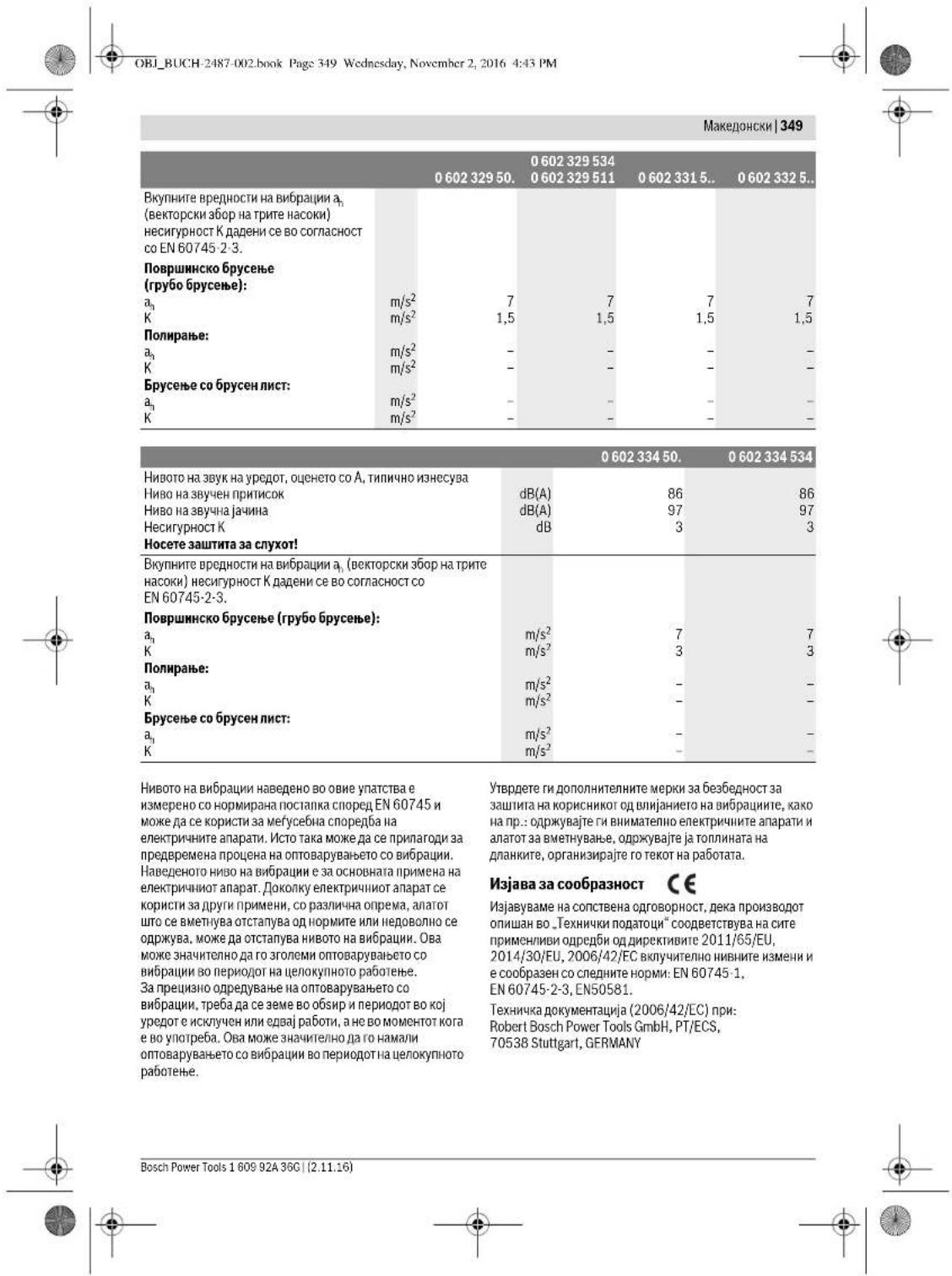
OBI_BUCH-2487-002.book Page 351 Wednesday, November 2, 2016 4:43 PM
Macedonian 351
Mount the guard, side handle, and auxiliary handle (BINCNKND1-D2)
For the following types:
-060230440
KopncTeHe
- YBepertce,IekaeMOHTnp xayba(BuDnMoHTnpaHeHa3awTNTHTEypeDn", ctrpa 350).
- NocstabeTJe ja pinnnynataa nppiap6nna 10 na bpehtoto 3a 6pceue 3.
Bo npHKnyHATA npHPa6HHa 10 konye HENTPAHNNOT BHeue cabeBnnaCTyH den (O-npCTeh).DOKKIXY HeoCTTHA O- nPCTEHOT OH OH eHTER, MOPaJa ce zAMEHN PpeJa cO MoNTHpaNPKHyHATA npPap6HHa 10.
- CnabeTo nocakyaBnHOT anat 3a6pycebe 11 (nnoa 3a 6pycebe, ceehe nnmCHe) Ha BPeteho 3a 6pycebe 3.
- Ctabete ja3e3hata HABPTKa 1.2 taka Ha HABOjTHa HABPTkata, ta0 cpeHATA dnaBHHa 3aTe3HATA HABPTKa nokKaYBHA horope. 3aupadepete ja 3aetehara haabptna co kynyot co da OBTHOPH13,dojeka co BmnykaKT kyny 14Ke pKHTHe NOBUPHINAT HA KYNYOT HA BPETHERO 3A6pBcEbe 3.
Orctpailynabe
JIKeTReO 10BcTe OpeTeHOTa 3a 6OpHyb3e C0 BHNUYUKACTN KTHyA noBnUPHHATA HKNHYOT 14. OdpTe ja aateshata HABPTKa 12 Co KnyoT co Dba OTBOPH 13 od BpTeHTo 3a 6pyCHe,doKeAco BHnyuKactHOT Kny 14 Ke dpKHe Ha nobPunHATA HA KNYoT. - 黎聶嶽詞 號nncsodobatennoanatot3a6bceheKaKIO npiKNUHNTA pnpaBnOAnD 0BpeHTo 0BaCpeHe.
EeKTPnHAnapnCoKoHc3aΦHKpHaHe HbPTeHOTo5
Baxn 3a cIe7HHTe TINOBH: -060232440 -0602324434 -060232444
Kaj enektpknihn anapatno co konque 3a fikncipahabe Ha bpehteno 5 otna4 dpkebeto co Bmnykact kny np MOnhakata ha anatot 3a 6pceneB (BnDn cnckn E-12)
To activate the drill, place it only in the drill holder while it is in the off state. The electrical device can be turned on. - Use the buttons for activating the drill 5 to activate the drill holder 3 by pressing the buttons. - Monitor the drilling indicator (monitor the drilling indicator, without pressing it, page 351).
- Release the locking mechanism of the drill 5 to activate the locking mechanism of the drill holder.
Mounting the rubber disc for drilling (see Figure F)
Spare parts list: -060230440. -060230540.
H00601806434
Use
- Make sure that the protective equipment for work is mounted (see, mounting of protective equipment, page 350).
- Place the rubber disc for drilling 17 on the drilling spindle for the drilling disc 16 on the rubber disc drilling.
- Place the round cap 15 on the drill spindle. - Tighten the round cap with the wrench 13, while with the pin 14 you will hold the drill spindle 3.
Make sure that the round cap 15 is not loose for tightening the rubber disc drilling, so that the drilling disc does not come off.
Operation
Press the drill switch 3 with the pin 14 until it reaches the surface or until you tighten the cap 15 with the wrench 13 from the drill holder, while with the pin 14 you will hold the surface of the cap. - Guide the drill bit into the rubber disc drilling.
Mounting the sanding disc (see Figure G)
Spare parts list: -06023014. -060232440 -060230540. -0602306434
Use
Fill the tank with oil for the exact type of oil for the time of casting (M14).
- Make sure that the protective equipment is installed and the additional equipment (see, Installation of the protective devices, page 350). Tighten the locking disc for support 18 at the time of casting 3, with the socket wrench against the pressure on the time key of the casting spindle, while with the socket wrench 14 press against the surface of the key of the casting spindle 3.

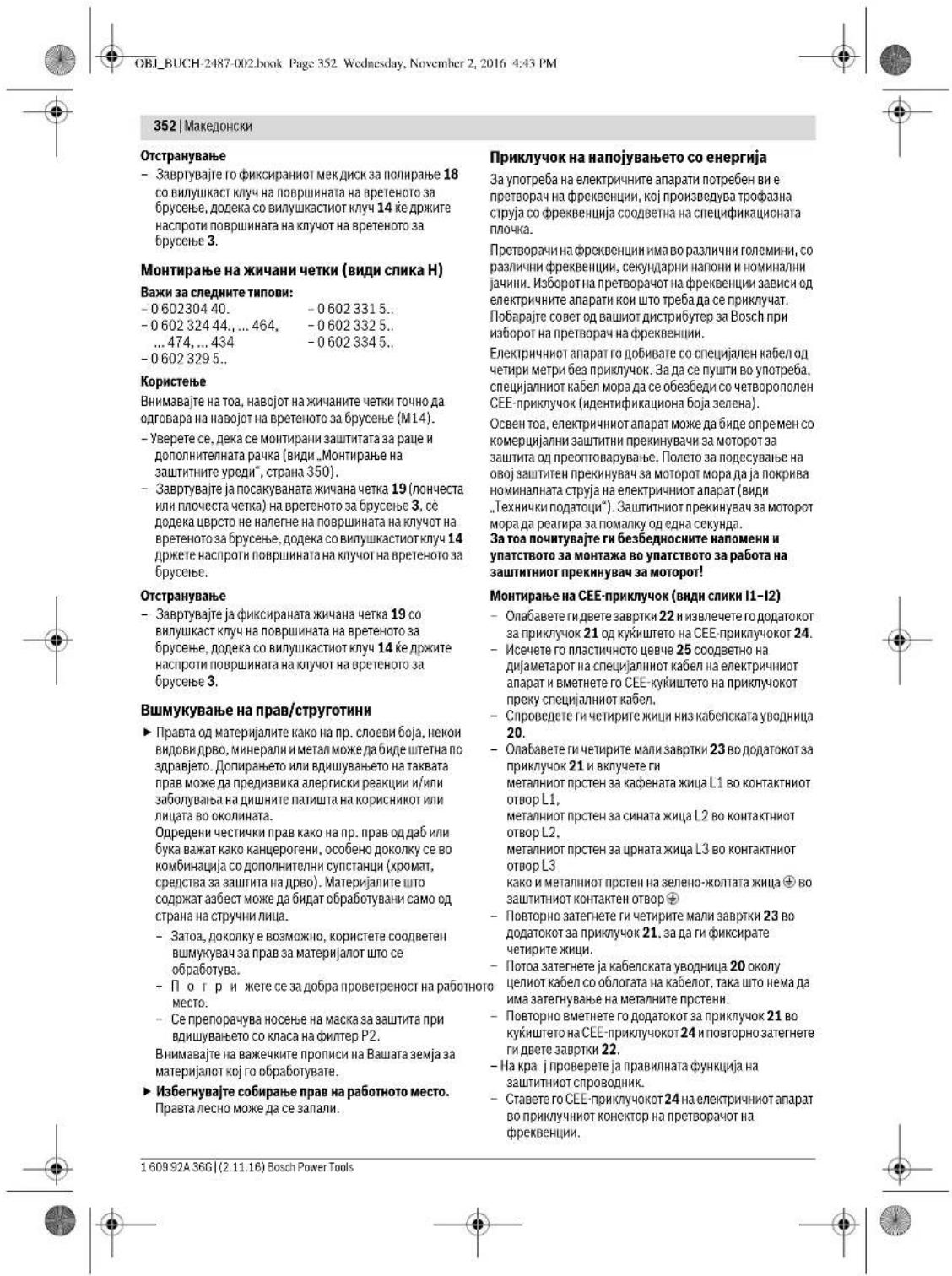

Macedonian 353
Now you can connect the frequency converter to the power supply.
How to connect the frequency converter to the power supply, follow the instructions in the section for working with the frequency converter.
At the end, check the spindle direction!
Checking the spindle direction
The direction of the spindle of the casting unit must correspond to the direction indicated by the arrow on the label of the electrical device.
If the casting unit at the first start-up rotates in the wrong direction, [see] "Switching on/off the electrical device", page 353), you must immediately switch off the electrical device and disconnect it from the power supply.
It opens the two locking screws 22, and then you will remove the cover for the connection 21 from the housing and the cover-connection 24 - remove the insulating plate from the cable entry and the contact block. - Then place the metal ring on the black cable L3 into the contact opening L1 and the metal ring of the cable L1 into the contact opening L3. - Repeat the tightening of the two locking screws 22 on the cable for the connection 21, then fix the cables and repeat the tightening of the cover for the connection 21 into the housing and the cover-connection 24 and repeat the tightening of the two locking screws 22. At the end, check the correct function of the protective devices. - Connect the electrical device again to the power supply.
Use
Putting into use
The frequency of the power supply must correspond to the specifications on the label of the electrical device. Check the pre-use and the casting unit. The casting unit must be installed without interruption and must be able to rotate freely. Make a test run of at least 1 minute without using the device on material. Do not use sharp, hard or abrasive casting plates that vibrate. Sharp casting plates can cause injuries and damage. Set the switch for switching on/off 1 in the position for switched off, when the electrical device is not intended to work, although the switch for switching on/off will be in the position for switched off. This will prevent unintentional restarting of the device. Check the power supply (see, "Connecting to the power supply", page 352), before switching on the electrical device again.
Always first connect the electrical device with the frequency converter, before you connect the frequency converter and the circuit breaker.
To turn on the device, plug the electrical appliance into the socket.
Switching on/off the device is done with the switch.
First, turn off the switch, then you can plug in the electrical appliance.
For this, follow the operating instructions or the switch on the device.
Switching on/off the electrical appliance with the rotary switch (see figure 1)
Important for the following types:
-06023244.
To switch on the electrical appliance, press the rotary switch for switching on/off 1 forward.
-To switch on/off with the rotary switch, press the rotary switch for switching on/off 1 forward, then release it.
To switch on the electrical appliance, press the rotary switch for switching on/off 1. When the rotary switch for switching on/off 1 is pressed, press it again and release it.
Switching on/off the electrical appliance with the rotary switch (see figure 2)
Important for the following types:
-06023014. -06023295.. -060230440. -06023315.. -060230540. -06023325.. -0602306434 -06023345..
-To put the electrical appliance into operation, press the rotary switch for switching on/off 1 and hold it pressed. Then press the rotary switch for switching on/off 1 again. Switch on the electrical appliance, release the rotary switch for switching on/off 1. When it is switched on, press the rotary switch for switching on/off 1 again and then release it.
Advice for operation
Before use, read the instructions for use carefully, in order to be able to use the device safely and to avoid misuse of the electric tool. These measures for safe use reduce the risk of injury from the electric tool. Pay attention to the safety instructions in the instructions for use.
Bosch Power Tools 1609 92A 36C (2.11.16)

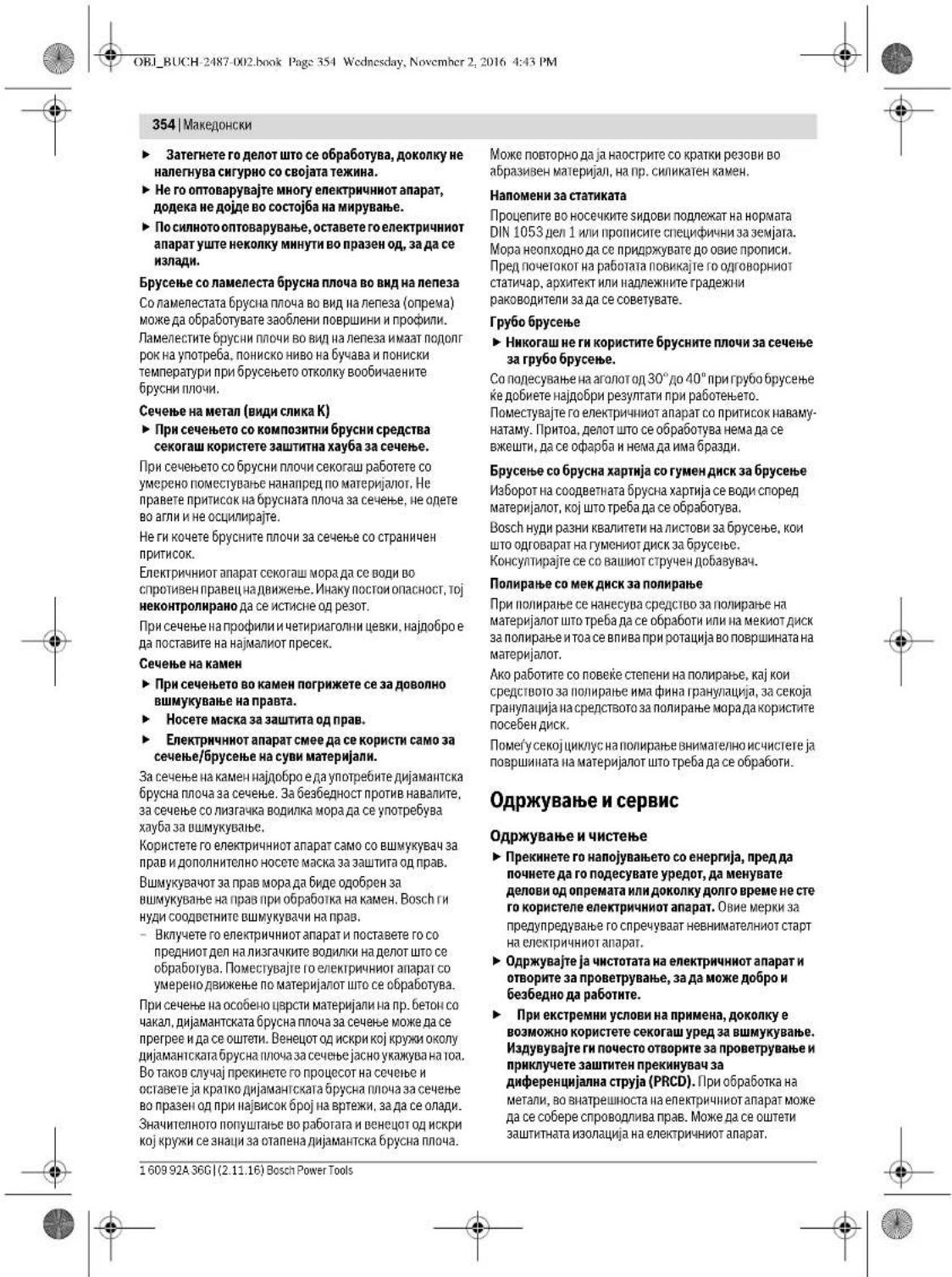
OBI_BUCH-2487-002.book Page 356 Wednesday, November 2, 2016 4:43 PM
356 | Serbian
Unmodified plugs and matching outlets will reduce risk of electric shock.
Avoid body contact with earthed surfaces such as pipes, radiators, ranges and refrigerators. There is an increased risk of electric shock if your body is earthed. Keep the appliance away from rain or moisture. Water entering a power tool will increase the risk of electric shock. Do not abuse the cord. Never use the cord for carrying, pulling or unplugging the power tool. Keep cord away from heat, oil, sharp edges or moving parts. Damaged or entangled cords increase the risk of electric shock. When operating a power tool outdoors, use an extension cord suitable for outdoor use. Use of a cord suitable for outdoor use reduces the risk of electric shock. If operating a power tool in a damp location is unavoidable, use a residual current device (RCD) protected supply. Use of an RCD reduces the risk of electric shock.
Personal safety
Stay alert, watch what you are doing and use common sense when operating a power tool. Do not use a power tool while you are tired or under the influence of drugs, alcohol or medication. A moment of inattention while operating power tools may result in serious personal injury. Use personal protective equipment. Always wear eye protection. Protective equipment such as dust mask, non-skid safety shoes, hard hat, or hearing protection used for appropriate conditions will reduce personal injuries. Prevent unintentional starting. Ensure the switch is in the off-position before connecting to power source and/or battery pack, picking up or carrying the tool. Carrying power tools with your finger on the switch or energising power tools that have the switch on invites accidents. Remove any adjusting key or wrench before turning the power tool on. A wrench or a key left attached to a rotating part of the power tool may result in personal injury. Do not overreach. Keep proper footing and balance at all times. This enables better control of the power tool in unexpected situations. Dress properly. Do not wear loose clothing or jewellery. Keep your hair, clothing and gloves away from moving parts. Loose clothes, jewellery or long hair can be caught in moving parts. If devices are provided for the connection of dust extraction and collection facilities, ensure these are connected and properly used. Use of dust collection can reduce dust-related hazards.
Careful use and handling of power tools
Do not overload the tool. Use the correct power tool for your work. With the appropriate power tool, you work better and more safely in the specified working area. Do not use any power tool whose switch is defective. Power tools that cannot be switched on or off are dangerous and must be repaired. Pull the plug out of the socket and/or remove the battery before making adjustments on the tool, changing accessories, or storing the tool. This precaution prevents unintentional starting of the power tool. Store unused power tools out of the reach of children. Do not allow persons who do not know the tool or have not read these instructions to use the tool. Power tools are dangerous when used by inexperienced persons. > Maintain power tools carefully. Check whether moving parts of the tool function safely and do not jam, whether parts are broken or damaged in such a way that the function of the power tool is impaired. Repair these damaged parts before use. Many accidents have their causes in poorly maintained power tools. Keep cutting tools sharp and clean. Carefully maintained cutting tools with sharp edges are less likely to jam and are easier to guide. Use power tools, accessories, inserted tools, etc. according to these instructions. Pay attention to the working conditions and the work to be performed. Using power tools for purposes other than those intended can lead to dangerous situations.
Service
Have your power tool repaired only by qualified personnel and only with original spare parts. This ensures that the safety of the tool is maintained.
| Visokofrekventa ugaona brusilica | |||||
| Vrsta zašite | IP 20 | IP 20 | IP 20 | IP 20 | |
| Napomene o napajanju Elektrichi nireedaj je deo visokofrekventnog systema i zahteva trofaznu naizmeničnu struju sa frekvencijom koja odgovara oznaci na pločici uredaja. | |||||
| Informacije o šumovima/vibracijama Vrednosti emisije šumova se odreduji u skladu sa EN 60745-2-3. | |||||
| 0 602 301 40. | 0 602 301 434 | 0 602 304 40. | 0 602 305 40. | ||
| A-vrednovan nivo šumova uredjaja iznosi tipićno Nivo zbućnog pritiska dB(A) | 72 | 82 | 79 | 76 | |
| Nivo snage vžuka dB(A) | 83 | 93 | 90 | 87 | |
| Nesigurnost K dB | 3 | 3 | 3 | 3 | |
| Nosite zašitu za sluh! Ukupne vrednosti vibracija a, (zbir vektora tri pracva) i nasigurnost K su dobujeni prema EN 60745-2-3. | |||||
| Brušanje povrsina (gruba obrada): | |||||
| a, m/s2 | - | 5,3 | 5 | - | |
| K m/s2 | - | 2 | 2 | - | |
| Poliranje: | |||||
| a, m/s2 | 3 | 3 | - | < 2,5 | |
| K m/s2 | 1,5 | 1,5 | - | 1,5 | |
| Brušanje sa brusnim listom: | |||||
| a, m/s2 | 3 | 3 | - | < 2,5 | |
| K m/s2 | 1,5 | 1,5 | - | 1,5 | |
| 0 602 306 434 | 0 602 324 40. | 0 602 324 44.0 0 602 324 44.0 0 602 324 44.0 0 602 324 44.0 0 602 324 44.0 0 602 324 44.0 0 602 324 44.0 0 602 324 | 0 602 324 44.0 0 602 324 44.0 0 602 324 44.0 0 602 324 44.0 0 602 324 44.0 0 602 324 44.0 0 602 32.4 44.0 0 602 324 44.0 0 602 324 44.0 0 602 324 44.0 0 602 324 44.0 0 602 324 44.0 0 602 324 44.0 0 1,5 | ||
| A-vrednovan nivo šumova uredjaja iznosi tipićno Nivo zbućnog pritiska dB(A) | 82 | 77 | 82 | ||
| Nivo snage vžuka dB(A) | 93 | 88 | 93 | ||
| Nesigurnost K dB | 3 | 3 | 3 | ||
| Nosite zašitu za sluh! | |||||
| Ukupne vrednosti vibracija a, (zbir vektora tri pracva) i nasigurnost K su dobujeni prema EN 60745-2-3. | |||||
| Brušanje povrsina (gruba obrada): | |||||
| a, m/s2 | - | - | 6 | ||
| K m/s2 | - | - | 2 | ||
| Poliranje: | |||||
| a, m/s2 | < 2,5 | 4 | - | ||
| K m/s2 | 1,5 | 1,5 | - | ||
| Brušanje sa brusnim listom: | |||||
| a, m/s2 | < 2,5 | 4 | - | ||
| K m/s2 | 1,5 | 1,5 | - | ||
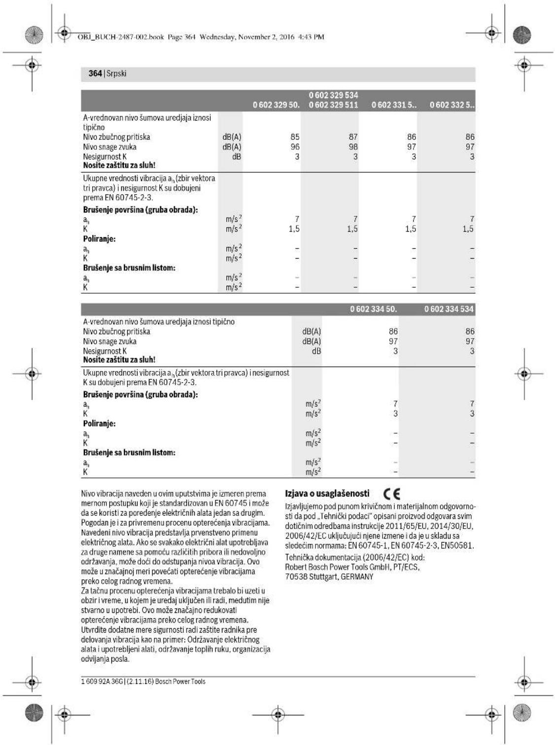
Henk Becker
Executive Vice President Engineering
Heimut Heinzelmann
Head of Product Certification PT/ECS

Robert Bosch Power Tools GmbH
70538 Stuttgart, GERMANY
Stuttgart, 01.01.2017
Assembly
Assembly of the protective devices
General instructions
Disconnect the power supply before making any adjustments to the device, replacing accessory parts, or leaving the electric tool. This precaution prevents accidental starting of the power tool.
Note: After the grinding disc breaks during operation or if the attachment device on the protective hood/power tool is damaged, the power tool must be sent to a service center immediately. For addresses, see the section "Service and Customer Advice".
Adjust the protective hood so that sparks are prevented from flying towards the operator.
Note: The coded lugs on the protective hoods ensure that only the protective hood that matches the power tool can be mounted.
Protective hood for grinding (see figure A)
Applies to the following types:
-060230440
-06023295..
-0602324434
-06023315
-060232444.
-06023325..
- Place the protective hood 6 with the guide pin 8 into the guide groove on the spindle neck 4 until the snap of the hood engages on the flange of the power tool.
- Adjust the position of the protective hood to the requirements of the work step.
- To secure the protective hood, tighten the clamping screw 7 to a tightening torque of at least 10 Nm.
especially in connection with additional materials for wood processing (chromates, wood preservatives). Material containing asbestos may only be worked on by specialists.
- Use as fine a dust extraction as possible suitable for the material. Ensure good ventilation of the workplace. - It is recommended to wear a breathing mask with filter class P2.
| Visokofrekvenčni kotni brusilnik | ||||
| Zašćitni razred | ©/I/I/I/I | © | © | © |
| Vrsta zašće | IP 20 | IP 20 | IP 20 | IP 20 |
The power tool is part of a high-frequency system and requires 3-phase current with a frequency in accordance with the specifications on the rating plate.
To achieve the specified frequency, you must connect the power tool to a frequency converter (see "Connection to the power supply", page 381).
| 0 602 329 50. | 0 602 329 534 | 0 602 331 5.. | 0 602 332 5.. | ||
| 0 602 329 511 | |||||
| Nivo hrupa naprave po vrednotenju Āznaša tipićno | |||||
| Nivo zvočnega tlaka | dB(A) | 85 | 87 | 86 | 86 |
| Nivo jakosti zvoka | dB(A) | 96 | 98 | 97 | 97 |
| Netočnost K | dB | 3 | 3 | 3 | 3 |
| Nosite zaščitne glušnike! | |||||
| Skupne vrednosti vibracij ān (vektorska vsota treh smeri) in negotovost K se izraču-najo v skladu z EN 60745-2-3. | |||||
| Bruşanje prevlek (kosmačanje): | |||||
| a1 | m/s2 | 7 | 7 | 7 | 7 |
| K | m/s2 | 1,5 | 1,5 | 1,5 | 1,5 |
| Poliranje: | |||||
| a1 | m/s2 | - | - | - | - |
| K | m/s2 | - | - | - | - |
| Bruşanje z brusilnim listom: | |||||
| a1 | m/s2 | - | - | - | - |
| K | m/s2 | - | - | - | - |
| 0 602 334 50. | 0 602 334 534 | ||
| Nivo hrupa naprave po vrednotenju A znaša tipično | |||
| Nivo zvočnegă tlaka | dB(A) | 86 | 86 |
| Nivo jakosti zvoka | dB(A) | 97 | 97 |
| Netočnost K | dB | 3 | 3 |
| Nosite zašcitne glušnike! | |||
| Skupne vrednosti vibracij a1 (vektorska vsota treh smeri) in negotovost K se izračunaj v skladu z EN 60745-2-3. | |||
| Bruşanje prevlek (kosmačanje): | |||
| a1 | m/s2 | 7 | 7 |
| K | m/s2 | 3 | 3 |
| Poliranje: | |||
| a1 | m/s2 | - | - |
| K | m/s2 | - | - |
| Bruşanje z brusilnim listom: | |||
| a1 | m/s2 | - | - |
| K | m/s2 | - | - |
Henk Becker
Executive Vice President Engineering
Heimut Heinzelmann
Head of Product Certification PT/ECS

Robert Bosch Power Tools GmbH
70538 Stuttgart, GERMANY
Stuttgart, 01.01.2017
Assembly
Mounting the protective equipment
General instructions
Before setting up the device, replacing accessory parts, or before putting away the power tool, you must disconnect the power supply. This precaution prevents unintentional starting of the power tool.
Warning: If the grinding wheel breaks during operation or if the guards on the protective cover/on the power tool are damaged, you must send the power tool to the service address; the address can be found in the section "Service and advice on use".
Adjust the protective cover so that sparks are prevented from flying towards the operator.
Switching the power tool on/off
with the safety lock-off switch (see figure J1)

Notes on the power supply
The power tool is part of a high-frequency system and requires three-phase current with a frequency according to the type plate for its operation.
For variable speed, the electronic device must be connected to a frequency converter (see "Connection to power supply", page 394).
Information on noise and vibration
394|Croatian
Press the spindle lock button only while the grinding spindle is at a standstill. Otherwise, the power tool could be damaged. - Before mounting the grinding tool, press the spindle lock button 5 to lock the grinding spindle 3 and keep the button pressed. - Mount the required grinding tool (see "Mounting the grinding disc, cutting disc, or roughing disc", page 393). - Release the spindle lock button 5 to unlock the grinding spindle.
Mounting the rubber sanding plate (see figure F)
General safety instructions
WARNING: Read all safety warnings and all instructions. Failure to follow the warnings and instructions may result in electric shock, fire and/or serious injury.
Estonian 405
| 0.60230140. | 0.602301434. | 0.60230440. | 0.60230540. | |
| Vibratsionitase \( a_{\mathrm {p}} \) (kolme telje vektorsum- ma) ja mõötemääramatus K, kindlaks teh- tud kooskolas standardiga EN 60745-2-3. | ||||
| Pinna lihvinmisel: | ||||
| \( a_{\mathrm {n}} \) | \( m/s^{2} \) | - | 5,3 | 5 |
| K | \( m/s^{2} \) | - | 2 | 2 |
| Poleerimisel: | ||||
| \( a_{\mathrm {n}} \) | \( m/s^{2} \) | 3 | 3 | - |
| K | \( m/s^{2} \) | 1,5 | 1,5 | - |
| Lihvaberiga lihvinmisel: | ||||
| \( a_{\mathrm {n}} \) | \( m/s^{2} \) | 3 | 3 | - |
| K | \( m/s^{2} \) | 1,5 | 1,5 | - |
406|Estonian
Henk Becker Helmut Heinzelmann Executive Vice President Head of Product Certification Engineering PT/ECS
iV. k = m
Robert Bosch Power Tools GmbH 70538 Stuttgart, GERMANY Stuttgart, 01.01.2017
Assembly
Estonian 407
408|Estonian
Removal
Estonian 409
410|Estonian
Static instructions
When cutting grooves into load-bearing walls, follow the guidelines of standard DIN 1053 Part 1 or the regulations of the respective country. These rules must be followed without exception. Before starting work, consult a qualified structural engineer, architect, or site manager.
Grinding
Latvian|413
The diameter and thickness of the accessory must match the design and dimensions of the power tool. If the accessory dimensions are incorrect, it will not be fully seated under the guard and will make the tool difficult to control during operation. Accessories fastened by means of a thread must precisely match the thread of the tool spindle. Accessories fastened by means of a flange must have an opening diameter that matches the locating diameter of the flange. Accessories that are not precisely mounted on the tool spindle will rotate unevenly, vibrate excessively, and may cause loss of control over the power tool. Do not use damaged accessories. Before each use, inspect the accessories for damage, for example, check that grinding discs are not chipped or cracked, that the grinding pad shows no cracks or tears, and that the wires of wire brushes are not loose or broken. If the power tool or an accessory has been dropped from a height, check whether it is damaged, or use an undamaged accessory. After inspecting and installing an accessory, let the power tool run at maximum no-load speed for one minute, holding the rotating accessory at a safe distance from yourself and other nearby persons. Damaged accessories will usually break during this test. ▸ Wear personal protective equipment. Depending on the work to be performed, choose a full face shield, safety goggles, or standard safety glasses. As needed, wear a dust mask, hearing protection, and protective gloves to protect against flying fragments of the accessory and the workpiece. Your eyes must be protected from flying debris generated during operation. The dust mask or respirator must protect your respiratory tract from dust generated during work. Prolonged exposure to high noise levels can cause permanent hearing damage. ▸ Ensure that other persons are at a safe distance from the work area. Anyone entering the work area must wear personal protective equipment. Fragments of the workpiece or a broken accessory can fly at high speed and cause injury to people even at a considerable distance from the work area. During operation, hold the power tool only by the insulated gripping surfaces, because the accessory may contact hidden wiring or the tool's own power cord. If the accessory contacts a live wire, the voltage will be transferred to the metal parts of the tool and may cause an electric shock. Keep the rotating accessory away from the power cord. If you lose control of the tool, the accessory may cut the cord or become entangled in it, and your hand or arm may come into contact with the rotating accessory.
Never operate the power tool until the working tool has come to a complete stop. The rotating working tool may come into contact with the supporting surface, as a result of which the power tool may become uncontrollable. Do not operate the power tool while carrying it. The operator's clothing or hair may accidentally come into contact with the rotating working tool and become entangled, causing the working tool to come into contact with the operator's body. Regularly clean the ventilation openings of the power tool. The air flow drawn in by the motor sucks dust into the tool housing, and a large accumulation of metal dust can cause electric shock. Do not use the power tool near flammable materials. Flying sparks can ignite such materials. Do not use working tools that require cooling liquid. The use of water or other liquid cooling agents can cause electric shock.
Kickback and related warnings
Kickback is a specific reaction of the tool that occurs when the rotating working tool, such as a grinding disc, grinding base, wire brush, etc., snags or jams. The snagging or jamming of the rotating working tool causes a sudden stop. As a result, the power tool is moved in the direction opposite to the direction of rotation of the working tool at the point of jamming, and often becomes uncontrollable. If, for example, a grinding disc snags or jams in the workpiece, the edge of the disc that is embedded in the workpiece can tear out of the workpiece or cause a kickback. In such a case, the grinding disc moves towards or away from the operator, depending on the direction of rotation of the disc relative to the workpiece. Furthermore, the grinding disc can break. Kickback is the result of improper or unskillful use of the power tool. It can be avoided by observing certain precautionary measures, which are described below.
Hold the power tool firmly and position your body and arms so that you can best resist the forces of kickback. Always use the auxiliary handle, if provided, to optimally control the kickback or reactive torque and maintain control over the tool. By taking certain precautionary measures, the operator can effectively counteract kickback and reactive torque in any situation. Do not bring your hands near the rotating working tool. In the event of a kickback, the working tool may also strike the operator's hand. Avoid being in the area where the power tool could move during a kickback. During a kickback, the power tool moves in the direction opposite to the direction of rotation of the working tool at the point of jamming. Exercise special care when working near corners and sharp edges. Do not allow the working tool to bounce off the workpiece or become jammed. When coming into contact with corners or sharp edges, the rotating working tool bends and bounces off the workpiece or becomes jammed. This can lead to loss of control over the power tool or kickback.

Do not use accessories that are damaged or unsuitable. Using such tools may cause kickback or lead to loss of control over the power tool. Special safety instructions for grinding and cutting: Use only grinding tools that are suitable for your power tool and the guard intended for such tools. The guard may not adequately cover unsuitable grinding tools, preventing you from achieving the desired level of safety. Curved grinding wheels must be mounted so that their grinding surface does not protrude beyond the edge of the guard. An incorrectly mounted grinding disc that protrudes beyond the guard edge cannot be adequately covered. For safety reasons, the guard must be firmly mounted on the power tool and adjusted so that the smallest possible part of the grinding tool is exposed towards the operator. The guard helps protect the operator from fragments and accidental contact with the grinding tool, as well as from flying sparks that can cause burns. Grinding tools may only be used for the purpose for which they are intended. For example, never use the side surface of a cutting disc for grinding. A cutting disc is intended for material processing with its cutting edge. Strong pressure on the side surface can break this tool. When using a curved grinding disc, use only an undamaged clamping flange of appropriate shape and size. A suitable clamping flange safely supports the grinding disc during work and reduces the risk of breakage. The clamping flanges used with cutting discs may differ from those used with other types of grinding discs. Do not use worn-out grinding discs that are intended for power tools with higher power. Grinding discs intended for larger power tools are not suitable for smaller power tools, whose speed is usually higher, and they may break during work.
Other special safety instructions for cutting
Do not apply excessive pressure to the cutting disc and do not allow it to jam. Do not make excessively deep cuts. Overloading the cutting disc causes it to bend or jam in the cut, which increases the risk of kickback or tool breakage. Avoid being in front of or behind the rotating cutting disc. If during work the operator moves the cutting disc away from themselves in the direction of the workpiece, in the event of kickback the power tool with the rotating cutting disc may be thrown directly towards the operator. When interrupting work or if the cutting disc jams, switch off the power tool and hold it still until the cutting disc has completely stopped. Do not attempt to pull the still rotating cutting disc out of the cut, as this may cause kickback. Determine and eliminate the cause of the disc jamming.
Do not switch the power tool on again if the inserted tool is still in the cut. After switching on, wait until the tool reaches full speed, and only then carefully continue cutting. Otherwise, the cutting disc may catch in the cut and be thrown out, which can also cause kickback. To reduce the risk of kickback, support the workpiece or large workpieces near the cut. Large workpieces may bend under their own weight. The workpiece must be supported on both sides, both near the cut and at the edge of the workpiece. Exercise particular caution when making plunge cuts in walls or other areas where the back side is not visible. When plunging the cutting disc into the material, it may come into contact with gas pipes, water pipes, electrical lines, or other objects, which can cause kickback and/or lead to injury.
Special safety instructions for sanding with sandpaper sheets: Do not use sanding sheets that are too large; choose sheets of the size recommended by the manufacturer. Sheets that extend beyond the sanding pad can cause injury, lead to snagging or tearing of the sheet, or cause kickback.
Special safety instructions for polishing
418 | Latvian
| Augstkrevnesc lenkslipmasina | ||||
| Maks. slipesanas diska diameters | mm 180 180 180 180 | |||
| Darbvärpstas vitne | M14 M14 M14 M14 | |||
| Svars atbilstoši EPTA-Procedure 01:2014 - ar pretvibracijas papildrokturi | kg 7,1 7,1 7,1 7,1 | |||
| Elektroaizsardžibas klase | ⊕ /1/1/1 | ⊕ | ⊕ | ⊕ |
| Aizsardžibas tips | IP 20 | IP 20 | IP 20 | IP 20 |
High-frequency angle grinder
| Izstradajuma numurs | 0 602 332 ... | |||||
| ... 501 | ... 504 | ... 507 | ... 534 | ... 511 | ||
| Nominálais spriegums | V 265 135 72 200 72 | |||||
| Frekvidence | Hz 200 200 200 300 300 | |||||
| Nominálá patéřejama jauda | W | 1950 | 1950 | 1950 | 2900 | 2900 |
| Nominálá izejas jauda | W | 1500 | 1500 | 1500 | 2200 | 2200 |
| Nominálá stráva | A | 5 | 10 | 18 | 10 | 27 |
| Griešanás atrums brivgaitá | min. -1 | 6600 | 6600 | 6600 | 6600 | 6600 |
| Maks. silpěsanas diska diametris | mm 230 230 230 230 230 | |||||
| Darbvarpastas vitne | M14 | M14 | M14 | M14 | M14 | |
| Svars atbilstósi EPTA-Procedure 01:2014 - ar pretvibrácijas papildrokturi | kg | 7,1 | 7,1 | 7,1 | 7,1 | 7,1 |
| Elektroázsardízas klase | # /T | # /T | # /T | # /T | # /T | |
| Aizsardzibas tips | IP 20 | IP 20 | IP 20 | IP 20 | IP 20 | |
High-frequency angle grinder
| Izsträdajuma numurs | 0 602 334 ... | ||||
| ... 501 | ... 504 | ... 507 | ... 534 | ||
| Nominālais spiregums | V 265 135 | 72 200 | |||
| Frekvence | Hz 200 200 200 300 | ||||
| Nominālā patērējamā jauda | W | 2500 | 2500 | 2500 | 3800 |
| Nominālā izejas jauda | W | 2200 | 2200 | 2200 | 3100 |
| Nominālā strāva | A | 6,7 | 13,2 | 24,7 | 13,2 |
| Griësanās Ātrums brivgaita | min. | 6600 | 6600 | 6600 | 6600 |
| Maks. sīlpēsanas diska diametrs | mm 230 230 230 230 | ||||
| Darbvärpstas vitne | M14 M14 M14 M14 | ||||
| Svars atbilstoši EPTA-Procedure 01:2014 | |||||
| - ar pretvibrăcijas papildrokturi | kg 7,8 7,8 7,8 7,8 | ||||
| Elektroaizsardžibas klase | €/t/1/t/1 | € | € | € | |
| Aizsardžibas tips | IP 20 | IP 20 | IP 20 | IP 20 | |
Instructions for electrical connection
The power tool is part of a high-frequency electrical supply system and requires a three-phase AC voltage with a frequency as specified on the rating plate.
To operate with this frequency, the power tool must be connected to a frequency converter (see section 'Connecting to the electrical supply', page 423).


Latvian | 419
420 | Latvian
| 0.602 329 50. | 0.602 329 534 | 0.602 331 5.. | 0.602 332 5.. | ||
| 0.602 329 511 | |||||
| Kopējā vibracijas paṭtrinajuma vīrtība a1(vektoru summa trijos virzienos) un izkliedeK ir noteikta atbilstōsī standartamEN 60745 2'3. | |||||
| Virsmu slipësana (rupjā): | |||||
| a1 | m/s2 | 7 | 7 | 7 | 7 |
| K | m/s2 | 1,5 | 1,5 | 1,5 | 1,5 |
| Pulešana: | |||||
| a1 | m/s2 | - | - | - | - |
| K | m/s2 | - | - | - | - |
| Slipësana ar sliploksni: | |||||
| a1 | m/s2 | - | - | - | - |
| K | m/s2 | - | - | - | - |
| 0 602 334 50. | 0 602 334 534 | |
| Instrumenta radita péc raksurlkines A izsvertà trokëna parametr tipiskãs vertibas ir sãdas: | ||
| skañas spiiedena limenis | dB(A) | 86 |
| skanas jaudas limenis | dB(A) | 97 |
| mèrijumu izkliede K | dB | 3 |
| Nësäjet ausu aizsargus! | ||
| Kopëjã vibracijas païtrinăjuma vīrtiBA \( a_{ij} \)(vektoru summa trijos virziños) un izkliede K ir noteikta atbilstoši standartam EN 60745-2-3. | ||
| Virsmu slipësana (rupjã): | ||
| \( a_{ij} \) | \( m/s^2 \) | 7 |
| K | \( m/s^2 \) | 3 |
| Puleësana: | ||
| \( a_{ij} \) | \( m/s^2 \) | - |
| K | \( m/s^2 \) | - |
| Slipësana ar sliploksni: | ||
| \( a_{ij} \) | \( m/s^2 \) | - |
| K | \( m/s^2 \) | - |
The declared vibration emission level has been measured in accordance with the standard EN 60745 specified procedure and can be used for comparing one power tool with another. It can also be used for a preliminary assessment of exposure to vibration.
The vibration emission level stated here applies to the main applications of the power tool. If the power tool is used for other applications, with different accessories or different application tools, or if it has not been maintained adequately, the vibration emission level may differ from the value stated here. This may significantly increase the vibration exposure over the total working period.
To accurately assess the vibration exposure over a given working period, also consider the times when the tool is switched off or running but not actually being used for the intended work. This may significantly reduce the vibration exposure over the total working period. Take additional measures to protect the operator from the harmful effects of vibration, such as maintaining the power tool and application tools in a timely manner, keeping hands warm, and organizing work patterns properly.
Executive Vice President Engineering
Helmut Heinzelmann
Head of Product Certification P1/ECS
Robert Bosch Power Tools GmbH
70538 Stuttgart, GERMANY
Stuttgart, 01.01.2017
160992A36G(2.11.16) Bosch Power Tools



Assembly
Attaching the protective devices
General instructions
Before adjusting the tool, changing accessories, or storing it, disconnect the power supply. Such precautionary measures prevent accidental starting of the power tool.
Note. If the grinding disc breaks during work or the fastening device on the protective guard or on the power tool is damaged, the power tool must be sent immediately to a service center, the address of which can be found in the section "Customer service and usage consultations".
Tighten the protective guard so that the spark flow does not point in the direction of the operator.
Note. The limiting device on the protective guard allows only a specific protective guard suitable for this power tool to be mounted on it.
Grinding protective guard (figure A)
For tools:
-060230440. -06023295.. -0602324434 -06023315.. -060232444. -06023325.. -0.602324464 -0.6023345 -0602324474 Insert the protective guard 6 into the limiting device 8 and turn it until the protective guard engages. Press it against the tool's flange. - Adjust the protective guard to a position that corresponds to the type of work to be performed. To secure the protective guard, tighten the clamping screw 7 with a torque of at least 10 Nm.
Cutting protective guard
For tools:
-060230440. -06023295.. -0602324434 -06023315.. -060232444. -06023325.. -0602324464 -06023345.. -0602324474
When cutting with grinding tools whose guide is made of composite materials, always use a cutting protective guard. When cutting stone, mount a cutting protective guard with a guide for stone cutting and a dust extraction connection (accessory) on the power tool.
The cutting protective guard is mounted on the power tool in a similar way to the standard protective guard (figure A).
Auxiliary handle with vibration damping (figure B)
Using the auxiliary handle with vibration damping significantly reduces the harmful effects of vibration, allowing you to work comfortably and with high efficiency. Use the power tool only when the auxiliary handle 2 is mounted on it.
- Depending on the nature of the work being performed, mount the auxiliary handle on the right or left side of the gear head. It is not permitted to make any modifications to the auxiliary handle. Stop using the auxiliary handle if it is damaged.
Auxiliary handle (figure C)
For tools:
When working with the rubber sanding pad 17, as well as with cup/disk brushes or with segmental sanding discs, always mount the auxiliary handle 9 on the tool.
The auxiliary handle 9 is mounted together with the auxiliary handle 2.
Mounting the sanding tools General instructions
Before adjusting the tool, changing accessories, or putting it away, disconnect the power supply. Such precautionary measures prevent accidental starting of the power tool. Use sanding tools of the appropriate size. The diameter of the central hole in the disc must match the dimensions of the backing pad. Do not use adapters or auxiliary devices to adjust the size. Clean the work spindle 3 and other mounting parts. After mounting the sanding tool and before switching on the power tool, check that the tool is correctly mounted and can rotate freely. Make sure that the sanding tool does not touch the guard or any other part of the power tool.
Mounting sanding, cutting, and rough sanding discs (figures D1 - D2)
For tools:
Mounting
- Ensure that a suitable guard is mounted on the tool (see section "Mounting the guard" on page 421).
- Place the backing pad 10 onto the work spindle 3 of the sander.
On the backing flange 10 there is a plastic part (ring insert) that centers the protrusion. If the ring insert is missing or damaged, the insert must be placed in the designated position before positioning the backing flange 10. Place the selected sanding tool 11 (grinding, cutting, or rough sanding disc) onto the sanding machine spindle 3, taking into account the spindle rotation direction.

- Place the clamping nut 12 onto the spindle thread so that the central recessed bolt is facing up.
- Tighten the clamping nut firmly with the two-pin spanner 13, while simultaneously placing the open-end spanner 14 on the spindle holding surface and using it to keep the spindle 3 stationary.
Removal
- Hold the sanding machine spindle 3 firmly with the open-end spanner 14 placed on the spindle holding surface.
- Unscrew the clamping nut 12 from the sanding machine spindle with the two-pin spanner 13, while holding the sanding machine spindle with the open-end spanner 14 placed on its holding surface. Then remove the sanding tool and the backing flange from the sanding machine spindle.
Power tools with spindle locking button 5
For tools:
When using power tools with spindle locking button 5, the sanding tool does not need to be held stationary with the open-end spanner during installation (see figures E1-E2).
Press the spindle locking button only when the power tool spindle is not rotating. Otherwise, the power tool may be damaged. Before installing the sanding tool, press the spindle locking button 5 to lock the power tool spindle 3, and keep the button pressed. Install the sanding tool (see section "Mounting the grinding, cutting, and rough sanding discs" on page 421). To release the spindle, release the spindle locking button 5.
Mounting the rubber sanding pad (figure F)
For tools:
Installation
- Make sure that the protective guard and auxiliary handle are installed on the tool (see section "Installing the protective guard" on page 421).
- Place the rubber sanding pad 17 onto the sanding spindle 3.
- Place the sanding sheet 16 onto the rubber sanding pad.
- Place the round nut 15 onto the thread of the sanding spindle. Using the two-pin wrench 13, tighten the round nut firmly, while simultaneously placing the open-end wrench 14 on the flats of the sanding spindle 3 and using it to hold the spindle.
Make sure that the round nut 15, after tightening, fits into the recess of the rubber sanding pad, does not obstruct the sanding process, and firmly holds the sanding sheet.
Removal
Firmly hold the sanding spindle 3 with the open-end wrench 14, which is placed on the flats of the spindle. - Unscrew the round nut 15 from the sanding spindle using the two-pin wrench 13, while holding the sanding spindle with the open-end wrench 14 placed on its flats. - Then remove the sanding sheet and the rubber sanding pad from the sanding spindle.
Mounting the polishing fleece (figure G)
For tools:
Installation
Make sure that the thread of the polishing fleece matches the thread of the sanding spindle (M14).
Make sure that the protective guard and auxiliary handle are installed on the tool (see section "Installing the protective guard" on page 421). Screw the polishing fleece 18 onto the sanding spindle 3 until it fits tightly against the flats of the sanding spindle, while holding the spindle steady with the open-end wrench 14, which is placed on the flats of the sanding spindle 3.
Loosen the tightly screwed-on wire brush 18 from the grinding machine spindle with the open-end wrench 14, which is located on the grinding machine spindle retaining plate.
Mounting the wire brush (figure H)
Tools:
-060230440. -06023315.. -060232444,...464, -06023325.. ...474,..434 -06023345. -06023295.
Mounting
Make sure that the thread of the wire brush exactly matches the thread of the grinding machine spindle (M14). Ensure that the tool has a protective guard and an auxiliary handle (see section "Protective devices" on page 421). Screw the desired wire brush or cup brush onto the grinding machine spindle as far as it will go, so that it sits firmly against the grinding machine spindle retaining plate, while tightening the spindle nut with the open-end wrench 14, which is located on the grinding machine spindle retaining plate.



Removal
- Loosen the tightly screwed-on wire brush 19 from the grinding machine spindle with the open-end wrench 14, which is located on the grinding machine spindle retaining plate.
Dust and chip extraction
Dust from certain materials, such as lead-containing paints, some wood types, minerals and metals, can be harmful to health. Contact with such dust or inhalation of it can cause allergic reactions and/or respiratory diseases in the power tool user or in persons in the vicinity of the workplace.
Dust from certain materials, such as dust produced when sawing oak or beech wood, can cause cancer, especially if the wood has been chemically treated (e.g., with chromium or wood preservatives). Materials containing asbestos may only be processed by persons with special professional training.
- Use the most suitable dust extraction method for the material being processed.
The workplace must be well ventilated.
- During work, it is recommended to use a mask for respiratory protection, filter class P2.
Observe the regulations in force in your country regarding the materials being processed.
Do not allow dust to accumulate in the workplace. Dust can easily ignite.
Connection to the power supply
To operate the power tool, a three-phase voltage with a frequency as indicated on the rating plate is required.
Frequency converters come in different sizes and produce different values, frequencies, and power of secondary voltage.
The selection of the frequency converter is determined by the parameters of the power tool to be connected. To choose the correct frequency converter, consult your local Bosch specialized dealer.
The power tool is supplied with a four-meter connecting cable without a plug. To enable high-frequency power tool operation, the connecting cable must be fitted with a four-pin CEE type plug (marked with green color).
To protect the power tool from overload, it can be equipped with a motor protection switch, which can be purchased at a retail store. The current setting range of the motor protection switch must cover the nominal current consumption of the power tool (see section "Technical Data"). The tripping time of the motor protection switch must be less than one second.
Observe the safety regulations and installation instructions provided with the motor protection switch.
Mounting the CEE type plug (Figures 11-12)
Unscrew both retaining screws 22 and pull the plug insert 21 out of the CEE type plug housing 24.
- Cut the flexible plastic sleeve 25 to a length corresponding to the diameter of the power tool's connecting cable, and slide the CEE type plug housing onto the connecting cable. Pull the four wires of the connecting cable through the strain relief clamp 20.
- Unscrew the four small screws 23 on the plug insert 21 and insert
the stripped end of the brown wire into contact L1, the stripped end of the blue wire into contact L2, the stripped end of the black wire into contact L3, and the stripped end of the green-yellow wire into the protective earth contact.
Now firmly screw the four small screws 23 of the plug housing 21, fixing the four connected cable wires. Then tighten the counter nuts of the strain relief clamp 20 so that the entire cable with its sheath is held firmly, but the wires in the contact inserts are not stretched. Push the plug housing 21 back into the CEE plug 24 housing and screw the two strain relief screws 22 back on. After assembly, check the proper functioning of the protective earth conductor. Connect the power tool's CEE plug 24 to the frequency converter's contact socket.
Now the frequency converter can be connected to the power supply.
When connecting the frequency converter to the power supply, follow the instructions in the converter's operating manual. Finally, check the power tool's spindle rotation direction.
Checking the rotation direction
The rotation direction of the power tool's spindle must match the direction of the arrow shown on the power tool.
If after the first switch-on (see section "Switching the power tool on and off", page 424) the spindle of the power tool rotates in the wrong direction, the power tool must be switched off immediately and disconnected from the power supply. Then unscrew the two strain relief screws 22 and pull the plug housing 21 out of the CEE plug 24 housing.
- Release the black and brown insulated ends and pull them out of the contact inserts.
- Then insert the black L3 insulated end into contact insert N1.1 and the brown L1 insulated end into contact insert N3. Firmly screw the small screws 23 on the plug housing 21, fixing the two swapped cable wires.
- Push the plug housing 21 back into the CEE plug 24 housing and screw the two strain relief screws 22 back on. After assembly, check the proper functioning of the protective earth conductor.
- Reconnect the power tool to the power supply.




424|Latvian
Operation
Starting operation
The output voltage and frequency of the power supply must correspond to the values specified on the nameplate of the power tool. Before use, check the grinding tools. First, make sure that the grinding tool is correctly installed and can rotate freely. Then perform a speed check of the tool by letting it run at full speed for at least 1 minute. Do not use damaged, unbalanced, or vibrating grinding tools. Damaged grinding tools may break during operation and cause injuries. ▸ Move the switch 1 to the "Off" position. If the power tool starts working immediately after connecting to the power supply, it is because the switch is in the "On" position. This will prevent uncontrolled restart of the power tool. Before restarting the power tool, check the power supply system (see section "Connecting to the power supply", page 423). Always first connect the power tool's CEE plug to the frequency converter's socket and only then connect the frequency converter to the mains power supply.
To save energy, switch on the power tool only when it is in use.
Switching the frequency converter on and off
Before switching on the power tool, always switch on the frequency converter.
When switching on the frequency converter, follow the instructions in the operating manual.
Switching the power tool on and off with the safety switch (figure J1)
For tools:
-06023244.
To switch on the power tool, push the switch 1 forward. To lock the switch 1, press the front part of the switch 1 until it clicks into the locked position. To switch off the power tool, release the switch 1. Briefly press and release the rear part of the locked switch 1.
Switching the power tool on and off with the safety switch (figure J2)
For tools:
-06023014. -06023295 -060230440 -06023315 -060230540. -06023325. -0.602306434 -0.6023345
- To switch on the power tool, push the switch 1 forward and then press it.
To lock the pressed switch 1 in the on position, push the switch 1 further forward. To switch off the power tool, release the switch 1, or briefly press and release the switch 1 if it is locked in the on position.
Instructions for work
Before adjusting the tool, changing accessories, or storing it, disconnect the power supply. This precautionary measure prevents accidental starting of the power tool. Be careful when cutting grooves and recesses in load-bearing walls; read the section "Static load". Securely clamp the workpiece so that it cannot move under its own weight. Do not overload the tool to the point where the spindle stops rotating. After operating the power tool under heavy load, let it run for a few minutes at no load to cool down the tool.
Sanding with segment sanding discs
Using segment sanding discs (accessory), you can work on curved surfaces and profiles.
Compared to conventional sanding discs, segment discs are more durable, produce lower noise levels, and result in lower working temperatures.
Cutting metal (figure K)
When cutting with abrasive tools based on composite materials, always use a protective guard for cutting.
Accessories
To fully explore the range of high-quality Bosch accessories, visit our websites www.boschpt.com and www.boschproductiontools.com or contact your local specialized dealer.
| Aukst dožnio kampinis šlifuoklis | |||||
| Gaminio numeris | 0 602 332 ... | ||||
| ... 501 | ... 504 | ... 507 | ... 534 | ... 511 | |
| Nominaloji Čatampa | V 265 135 72 200 72 | ||||
| Dažnis | Hz 200 200 200 300 300 | ||||
| Nominali naudojamoji galia | W 1950 1950 1950 2900 2900 | ||||
| Nominali atiduodamoji galia | W 1500 1500 1500 2200 2200 | ||||
| Nominaloji srové | A 5 | 10 18 10 27 | |||
| Tušciosios eigos sikiq skiačius | min-1 | 6600 6600 6600 6600 6600 | |||
| Maks. šlifavimo disko skersmuo | mm 230 230 230 230 230 | ||||
| Šlifavimo suklio sriegis | M14 M14 M14 M14 M14 | ||||
| Svoris pagal „EPTA-Procedure 01:2014" - su vibracija slopinancia papildoma rankena | kg | 7,1 | 7,1 | 7,1 | 7,1 |
| Apsaugos klase | ⊕/I | ⊕/I | ⊕/I | ⊕/I | |
| Apsaugos lipas | IP 20 | IP 20 | IP 20 | IP 20 | |
| Aukstoto dažnio kampinis šlifuoklis | |||||
| Gaminio numeris | 0 602 334 ... | ||||
| ... 501 | ... 504 | ... 507 | ... 534 | ||
| Nominaloji Ātampa | V | 265 | 135 | 72 | 200 |
| Dažnis | Hz | 200 | 200 | 200 | 300 |
| Nominali naudojamoji galia | W | 2500 | 2500 | 2500 | 3800 |
| Nominali atiduadamoji galia | W | 2200 | 2200 | 2200 | 3100 |
| Nominaloji srové | A | 6,7 | 13,2 | 24,7 | 13,2 |
| Tušciosios eigos sukijski skáčius | min-1 | 6600 | 6600 | 6600 | 6600 |
| Maks. šlifavimo disko skersmuo | mm | 230 | 230 | 230 | 230 |
| Šlifavimo suklio sriegis | M14 | M14 | M14 | M14 | |
| Svoris pagal „EPTA-Procedure 01:2014“ - su vibracija slopınancia papildoma rankena | kg | 7,8 | 7,8 | 7,8 | 7,8 |
| Apsaugos klase | ®/I | ®/I | ®/I | ®/I | |
| Apsaugos tipas | IP 20 | IP 20 | IP 20 | IP 20 | |
Removal
- Hold the sanding spindle lock 14 with a 14 mm open-end wrench placed on the flats of the sanding spindle. Unscrew the clamping nut 12 with the ring spanner 13 from the sanding spindle, while holding the wrench 14 on the flats of the sanding spindle. Then remove the sanding tool and the backing pad from the sanding spindle.
Power tool with spindle lock key 5
Applies to the following types:
-060232440, -0602324434, -060232444
438|Lithuanian
- It is recommended to wear respiratory protection with P2 class filter.
Observe the regulations applicable in your country for the disposal of waste materials.
Ensure that dust does not accumulate at the workplace. Dust can easily ignite.
Lithuanian 439
To lock the switch 1 in the ON position, press the front part of the switch 1 down until it engages. To switch off the power tool, release the switch 1.
To unlock the switch 1, briefly press it down and then release it.
Switching the power tool on/off
with a safety switch (see Fig. J2)
Applies to the following types:
-06023014.. -06023295.. -060230440. -06023315.. -060230540. -06023325.. -0602306434 -06023345..
- To switch on the power tool, push the on/off switch 1 forward and then press it. To lock the pressed on/off switch 1, push the on/off switch 1 further forward. To switch off the power tool, release the on/off switch 1 or, if it is locked, briefly press and then release the on/off switch 1.
Working advice
Lqin L20
aJdo aaliso jao gglucgi wggs
.
JALL
gjol oJlgl Jol Jol Uo Jowll sic
oJlJI abw JIJI JIJI Ug jg Ig IqJIy
aJgJdAsJdGjbJc dibwJg
aJg<10sJlabg
(J1 oJgJgJ) JloJ gJj elao go
:ulluljIbllgfoaI aJlu
06023244..
Jusuill elao g 8y ayiluyl 10sll Jusu
p0a1y1 1 Lbgy
1lablgjduaiuulgluo -ao sao uus
.(gduuUJUJawU1LabgUusuUeio
06023295.. -06023014.
-06023315.. -060230440
-06023325.. -060230540.
-06023345.. -0602306434
06023315.. - 060230440.
-060283202.32444.,...464; -06023345...474,...434
-06023295..
060232440.-06023014..
-060230540.
-0602306434
#
g a d jd 111111111111111111111111111111111
(445 aaaa, "aLgllljjj
aagg 9 a jd d o wll s 3 aalj ggs 1gc qy (aaeg g 1 aalj jgds yagai jsj baw lc lksj 14 1giai iia jjs -p 0g qlaol aaal jgds yagai jsj abw
山
1000000000000000000000000000000000000000000000000000000000000000000000000000000000000
jull/JIbaw
Jc g y jlll k 1 g, n Jn Jn Jn Jn Jn Jn Jn Jn Jn Jn Jn Jn Jn Jn Jn Jn Jn Jn Jn Jn Jn Jn Jn Jn Jn Jn Jn Jn Jn Jn Jn Jn Jn Jn Jn Jn Jn Jn Jn Jn Jn Jn Jn Jn Jn Jn Jn Jn Jn Jn J.
#
-
445 aovall “aylogll Ujugai csji 1)
-3
Jolbolljoo 16 oaiall aaggus aJgJ 15 gol JJIgdoabwgljuSdUaJgolJIbJpS 14 13 12 11 10 9 8 7 6 5 4 3 2 1 0 8 7 6 5 4
gaw jia aalj u jgs jgdo lc yai all
1.14 agioai bll alao abwgl aioJI jSjI bll alao abw 5y ssowal agolal elg
060232440.- 06023014..
-060230540. -0602306434
17 10000000000000000000000000000000000000000000000000
2 9 1
10 1 1 1 1 1 1 1 1 1 1 1 1 1 1 1 1 1
__SUPPIMER__
The quick brown fox jumps over the lazy dog. The quick brown fox jumps over the lazy dog. The quick brown fox jumps over the lazy dog.
(D2-D1) mm
Additional information
06023315.. - 060230440.
-060283302.32444.,...464;
-06023345...474,...434
-060230440.
Jl jll 8 aJl JI aolSj6 aIgll Ubc js - Ubc ggb ju UJ4 uJg JI goo ic Uc .ajluqsl oJl aaaw lc aylogl
7 uuiu gui yaiugaiuee uoiui 10guy
. JosJ aJoo i Jg j0j
gbaUaLg 1
:JUJI UJUJUJU JgsoJU JU
-06023295.. 06023295.. - 060230440.
-06023315..
-06023325.
-gj)aJallagglUac0602938455u
-0602324434
-060232444.
-0602324464
-0602324474
.(445aJJI,“吕gJI UJqSj
| 0 602 329 5340 602 329 5110 6080083129.8602 332 5.. | |||||
| ah ∫jljzjxjxjxjxjxjxjxjxjxjxjxjxjxjxjxjxjxjxjxjxjxjxjxjxjxjxjxjxjxjxjxjxjxjxjxjxjxjxjxjxjxjxjxjxjxjxjxjxjxjxjX | |||||
| 7 | 7 | 7 | 7 | 2u/ρ | ah |
| 1,5 | 1,5 | 1,5 | 1,5 | 2u/ρ | K |
| :JLJL | |||||
| - | - | - | - | 2u/ρ | ah |
| - | - | - | - | 2u/ρ | K |
| :JLJL | |||||
| - | - | - | - | 2u/ρ | ah |
| - | - | - | - | 2u/ρ | K |
| 0 602 334 50.0 602 334 534 | |||
| 86 | 86 | (A) بسیل | العاءة الحرفية (A عو) بعسiguالعاء |
| 97 | 97 | (A) بسیل | العاءة الحرفية (A عو) بعسiguالعاء |
| 3 | 3 | (d) بسیل | K üglaill !العاء |
| aIJü/ρ ah üljūmī λιتَبْعاء .EN 60745-2-3 υمُّهُ K üglaillg (العاء | |||
| 7 | 7 | 2U/ρ | ah |
| 3 | 3 | 2U/ρ | K |
| :aIJü/ρ | |||
| - | - | 2U/ρ | ah |
| - | - | 2U/ρ | K |
| :aIJü/ρ | |||
| - | - | 2U/ρ | ah |
| - | - | 2U/ρ | K |
Directive 2011/65/EU (RoHS)
2004/108/EC:2016 19
2006/42/EC, 2014/30/EU: 2016, 2014, n·g
jglalgo golgiog lqle 1b 1u 1u
.EN50581, EN60745-2-3, EN60745-1:
:2006/42/EC)Jd
Robert Bosch Power Tools GmbH, PT/ECS
70538 Stuttgart, GERMANY
Henk Becker
Senior Vice President
Engineering
Helmut Heinzelmann
Head of Product Certification
PT/ECS
Robert Bosch Power Tools GmbH,
70538 Stuttgart, GERMANY
Stuttgart, 01.01.2017
EN60745 1
. 1
| 200 | ||||
| 300 | 200 | 200 | \( {}^{1} \) | \( {}^{1} \) |
| 900 | 600 | 600 | \( {}^{1} \) | \( {}^{1} \) |
| 630 | 440 | 440 | \( {}^{1} \) | \( {}^{1} \) |
| 3,3 | 3,3 | 1,6 | \( {}^{1} \) | \( {}^{1} \) |
| 6 150 | 4100 | 4100 | \( {}^{1} \) | \( {}^{1} \) |
| 125 | 125 | 125 | \( {}^{1} \) | \( {}^{1} \) |
| M14 | M14 | M14 | \( {}^{1} \) | |
| 3,2 | 3,2 | 3,2 | \( {}^{1} \) | \( {}^{1} \) |
| \( {}^{1} \)/I | \( {}^{1} \)/I | \( {}^{1} \)/I | \( {}^{1} \) | |
| IP 20 | IP 20 | IP 20 | \( {}^{1} \) |
| ...404 | 0 602 305 ... ... 401 | ... 407 | 0 602 304 ... ... 404 | الصحيى | |
| 135 | 265 | 72 | 135 | ف�� | الجِدُّلَيْ |
| 200 | 200 | 200 | 200 | سَرْ | الجِدُّلَيْ |
| 950 | 950 | 950 | 950 | بَع | الجِدُّلَيْ |
| 700 | 700 | 700 | 700 | بَع | الجِدُّلَيْ |
06023014..
060230540:
0602306434
060232440:
The device is designed to be used in accordance with the instructions provided in this manual. It is important to read and understand all safety information before operating the equipment.
g 1000 1000 1000 1000 1000 1000 1000 1000 1000 1000 1000 1000 1000 1000 1000 1000 1000 1000 1000 1000 100
The device is equipped with a safety feature.
The device should be operated at a temperature of 1. jc 100g
The device is designed for indoor use only.
do s0 g s0 sic u y mc u wll osc y jy 4y
The device should be installed by a qualified technician. Ensure that the power supply is disconnected before any maintenance.
__SUPPIMER__
The product is designed for use in accordance with the instructions. It should be used only as directed. The manufacturer is not liable for any damage resulting from misuse. (See also the safety instructions.)
The device must be installed by a qualified technician (see the installation guide) and used in accordance with the safety regulations.
Reference: 0602324.
__SUPPERIMER__
21 23 24 25 26 27 28 29 30 31 32 33 34 35 36 37 38 39 40
21 22 23 24 CEE
06023315.. - 060230440. -06023325.. -060232444. -06023345...474,...434 -06023295..
- liabollsas
∴ ΔJ 1 ΔgS _ i OS = 2 0
- | _ j | _ j | _ j | _ j | _ j | _ j ρ_ a ^ 2
∴ 2 y 1. 2 g = 0. 5 ≈ 0
ω_ 1 ω_ 2 ω_ 3 ω_ 4
| g | 3 | 10 | (μj oq) | j | j | j | j | j | j | j | j | j | j | j | j | j | j | j | j | j | j | j | j | j | j | j | j | j | j | j | j | j | j | j | j | j | j | j | j | j | j | j | j | j | j | j | j | j | j | j | j | j | j | ||||||||||||||||||||||||||||||||||||||||||||||||||
| g | 3 | 10 | (μj oq) | j | j | j | j | j | j | j | j | j | j | j | j | j | j | j | j | j | j | j | j | j | j | j | j | j | j | j | j | j | j | j | j | j | j | j | j | j | j | j | j | j | j | ||||||||||||||||||||||||||||||||||||||||||||||||||||||||||
| g | 3 | 10 | (μj o q) | j | j | j | j | j | j | j | j | j | j | j | j | j | j | j | j | j | j | j | j | j | j | j | j | j | j | j | j | j | j | j | j | j | j | j | j | j | j | j | j | j | j | j | j | j | j | j | j | j j j j j j j j j j j j j j j j j j j j j j j j j j j j j j j j j j j j j j j j j j j j j j j j j j j | - | - | - | - | - | - | - | - | - | - | - | - | - | - | - | - | - | - | - | - | - | - | - | - | - | - | - | - | - | - | - | - | - | - | - | - | - | - | - | - | - | - | - | - | - | - | - | - | - | - | |
| g | 3 | 10 | (μj o q) | j | j | j | j | j | j | j | j | j | j | j | j | j | j | j | j | j | j | j | j | j | j | j | j | j | j | j | j | j | j | j | j | j | j | j | j | j | j | j j j j j j j j j j j l l l l l l l l l l l l l l l l l l l l l l l l l l l l l l l l l l l l l l l l l l l l l l l l l l i j k l l l l l l l l l l l l l l l l l l l l l l l l l l l l l l l l l l l l l l l l l l l l l l l l l 13 (a j g w g l a l j l l l l l l l l l l l l l l l l l l l l l l l l l l l l l l l l l l l l l l l l l l l l l l l l l l l l l l l l l l l l l l l l l l l l l l l l l l l l l l l l l l l l l l l l l l l l l l l l l l l l g w g l a l j l l l l l l l l l l l l l l l l l l l l l l l l l l l l l l l l l l l l l l l l l l l l l l l l l l l l l l l l l l l l l l l l l l l l l l l l l l l l l l l l l l l l l l l l l l l l l g w g l a i l c a l j l l l l l l l l l l l l l l l l l l l l l l l l l l l l l l l l l l l l l l l l l l l l l l l l l l l l l l l l l l l l l l l l l l l l l l l l l l l l l l l l l l l l l l l l l l l l l l l l g w w g l a i l c a l j l l l l l l l l l l l l l l l l l l l l l l l l l l l l l l l l l l l l l l l l l l l l l l l l l l l l l l l l l l l l l l l l l l l l l l l l l l l l l l l l l l l l l l l l l g w w g l a i l c d j o q a s d j o q a s d j o q a s d j o q a s d j o q a s d j o q a s d j o q a s d j o q a s d j o q a s d j o q a s d j o q a s d j o q a s d j o q a s d j o q a s d j o q a s d j o q a s d j o q a s d j oq a s d j o q a s d j o q a s d j o q a s d j o q a s d j o q a s d j o q a s d j o q a s d j o q a s d j o q a s d j o q a s d j o q a s d j o q a s d j o q a s d j o q a s d j o q a s d j o q a s d g w w g l a i l c d j o q a s d j o q a s d j o q a s d j o q a s d j o q a s d j o q a s d j o q a s d j o q a s d j o q a s d j o q a s d j o q a s d j o q a s d j o q a s d j o q a s d j o q a g w w g l a i l c d j o q a s d j o q a s d j o q a s d j o q a s d j o q a s d j o q a s d j o q a s d j o q a s d j o q a s d j o q a s d j o q a s d j o q a s d j o q a s d j o q a s d j o q a 14 j 12 j 12 j 12 j 12 j 12 j 12 j 12 j 12 j 12 j 12 j 12 j 12 j 12 j 12 j 12 j 12 j 12 j 12 j 12 j 12 j 12 j 12 j 12 j 12 j 12 j 18 j 18 j 18 j 18 j 18 j 18 j 18 j 18 j 18 j 18 j 18 j 18 j 18 j 18 j 18 j 18 j 18 j 18 j 18 j 18 j 18 j 18 j 18 j 18 j 18 j 12 14 14 14 14 14 14 14 14 14 14 14 14 14 14 14 14 14 14 14 14 14 14 14 14 14 14 14 14 14 14 14 14 14 14 g w w g l a i l c d j o q a s d j o q a s d j o q a s d j o q a s d j o q a s d j o q a s d j o q a s d j o q a s d j o q a s d j o q a s d j o q a s d j o q a s d j o q a s d j o q a s d j o q a g w w g l a i l c d j o q a s d j o q a s d j o q a s d j o q a s d j o q a s d j o q a s d j o q a s d j o q a s d j o q a s d j o q a s d j o q a s d j o q a s d j o q a s d j o q a s d j o q a s g w w g l a i l c d j o q a s d j o q a s d j o q a s d j o q a s d j o q a s d j o q a s d j o q a s d j o q a s d j o q a s d j o q a s d j o q a s d j o q a s d j o q a s d j o q a s d j o q a d j o q a s d j o q a s d j o q a s d j o q a s d j o q a s d j o q a s d j o q a s d j o q a s d j o q a s d j o q a s d j o q a s d j o q a s d j o q a s d j o q a s d j o q a s d j o q a s d j o q g w w g l a i l c d j o q a s d j o q a s d j o q a s d j o q a s d j o q a s d j o q a s d j o q a s d j o q a s d j o q a s d j o q a s d j o q a s d j o q a s d j o q a s d j o q a s d j o q a 0.60232440.. - - - - - - - - - - - - - - - - - - - - - - - - - - - - - - - - - - - - - - - - - - - - - - - - - - - - - - - - - - - - - - - - - - - - - - - - - - - - - - - - - - - - - - - - - - - - - - - - - - - - - g w w g l a i l c d j o q a s d j o q a s d j o q a s d j o q a s d j o q a s d j o q a s d j o q a s d j o q a s d j o q a s d j o q a s d j o q a s d j o q a s d j o q a s d j o q a s d j o q a s g w w g l a i l c d j o q a s d j o q a s d j o q a s d j o q a s d j o q a s d j o q a s d j o q a s d j o q a s d j o q a s d j o q a s d j o q a s d j o q a s d j o q a s d j o q a s d j o q a S g w w g l a i l c d j o q a s d j o q a s d j o q a s d j o q a s d j o q a s d j o q a s d j o q a s d j o q a s d j o q a s d j o q a s d j o q a s d j o q a s d j o q a s d j o q a s d j o q a 0.60232440.. - - - - - - - - - - - - - - - - - - - - - - - - - - - - - - - - - - - - - - - - - - - - - - - - - - - - - - - - - - - - - - - - - - - - - - - - - - - - - - - - - - - - - - - - g w w g l a i l c d jo q a s d jo q a s d jo q a s d jo q a s d jo q a s d jo q a s d jo q a s d jo q a s d jo q a s d jo q a s d jo q a s d jo q a s d jo q a s d jo q a s d jo q a s d jo q a s d jo q a s d jo 15 j 12 j 12 j 12 j 12 j 12 j 12 j 12 j 12 j 12 j 12 j 12 j 12 j 12 j 12 j 12 j 12 j 12 j 12 j 12 j 12 j 12 j 12 j 12 j 12 j 14 14 14 14 14 14 14 14 14 14 14 14 14 14 14 14 14 14 14 14 14 14 14 14 14 14 14 14 14 14 14 14 14 |
Vibration Control
Directive (2006/42/EC)
Robert Bosch Power Tools GmbH, PT/ECS
70538 Stuttgart, GERMANY
Henk Becker
Senior Vice President
Engineering
Helmut Heinzelmann
Head of Product Certification
PT/ECS
Robert Bosch Power Tools GmbH,
70538 Stuttgart, Germany
Stuttgart, 01.01.2017
06023295:
06023315:
06023325.
06023345:
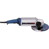


- HWS
- BOSCH
- DEUTSCH
- ASSEMBLY
- GENERAL POWER TOOL SAFETY WARNINGS
- WORK AREA SAFETY
- ELECTRICAL SAFETY
- PERSONAL SAFETY
- POWER TOOL USE AND CARE
- SERVICE
- SAFETY WARNINGS FOR ANGLE GRINDER
- APPLIES FOR THE FOLLOWING TYPES
- APPLIES FOR ALL TYPES
- KICKBACK AND RELATED WARNINGS
- SAFETY WARNINGS SPECIFIC FOR GRINDING AND ABRASIVE CUTTING-OFF OPERATIONS
- SAFETY WARNINGS SPECIFIC FOR POLISHING OPERATIONS
- SAFETY WARNINGS SPECIFIC FOR WIRE BRUSHING OPERATIONS
- ADDITIONAL SAFETY WARNINGS
- WEAR SAFETY GOGGLES
- PRODUCT DESCRIPTION AND SPECIFICATIONS
- INTENDED USE
- SAFETY WARNINGS FOR THE POWER SUPPLY OF HIGH-FREQUENCY TOOLS
- NOTES ON THE POWER SUPPLY
- NOISE/VIBRATION INFORMATION
- MOUNTING THE PROTECTIVE DEVICES
- GENERAL INFORMATION
- PROTECTION GUARD FOR GRINDING (SEE FIGURE A)
- PROTECTION GUARD FOR CUTTING
- APPLIES TO THE FOLLOWING TYPES
- VIBRATION-DAMPENING
- AUXILIARY HANDLE
- (SEE FIGURE B)
- HAND GUARD (SEE FIGURE C)
- MOUNTING THE GRINDING TOOLS
- MOUNTING GRINDING OR CUTTING DISCS (SEE FIGURES D1-D2)
- INSTALLATION
- REMOVAL
- MACHINES WITH SPINDLE LOCK BUTTON
- MOUNTING THE RUBBER SANDING PLATE (SEE FIGURE F)
- MOUNTING THE BUFFING DISC (SEE FIGURE G)
- MOUNTING WIRE BRUSHES (SEE FIGURE H)
- DUST/CHIP EXTRACTION
- CONNECTION TO THE POWER SUPPLY
- MOUNTING THE CEE PLUG (SEE FIGURES 11-12)
- CHECKING THE ROTATION DIRECTION
- OPERATION
- STARTING OPERATION
- SWITCHING THE FREQUENCY CONVERTER ON/OFF
- SWITCHING THE POWER TOOL ON/OFF WITH THE ON/OFF SWITCH (SEE FIGURE J1)
- SWITCHING THE POWER TOOL ON/OFF
- WITH SAFETY SWITCH (SEE FIGURE J2)
- WORKING ADVICE
- SANDING WITH THE FLAP DISC
- CUTTING METAL (SEE FIGURE K)
- CUTTING STONE
- INFORMATION ON STRUCTURES
- ROUGH GRINDING
- SANDING WITH SANDING DISCS AND THE RUBBER SANDING PLATE
- SPANISH
- DUTCH
- NEDENLADS
- SWEDISH
- VIBRATION-DAMPING AUXILIARY HANDLE (SEE FIGURE B)
- WASTE DISPOSAL
- FINNISH
- SAFETY INSTRUCTIONS
- PRODUCT DESCRIPTION AND POWER
- SUITABLE FOR THE FOLLOWING TYPES
- ILLUSTRATED COMPONENTS
- SIGMA
- SAFETY INSTRUCTIONS FOR POWER TOOLS
- GENERAL SAFETY WARNINGS
- SAFETY INSTRUCTIONS FOR SANDING (BETA VERSION A) APPLY TO THE FOLLOWING TYPES
- GREEK
- LAY IT FLAT ON THE FLOOR
- TONOBTTN
- FUNCTION OF THE AIR FILTER (SEE FIGURE G)
- IMPORTANT SAFETY INSTRUCTIONS
- SWITCHING ON/OFF OF THE SWITCH
- FOR THE AUTOMATIC OPERATION OF THE DEVICE, USE THE SWITCH (SEE FIGURE J1)
- FOR THE FOLLOWING TYPES
- FOR THE AUTOMATIC OPERATION OF THE DEVICE
- WITH THE SWITCH (SEE FIGURE J2)
- MAINTENANCE
- OPERATION WITH THE REMOTE CONTROL
- CHIMNEY CLEANING
- INSTALLATION INSTRUCTIONS
- EXPLANATIONS REGARDING THE POWER SUPPLY
- TURKISH
- DECLARATION OF CONFORMITY
- C
- POLSKI
- CZECH
- SANDING WITH SANDPAPER ON A SANDING PAD
- SLOVAK
- INFORMATION ON POWER SUPPLY
- HUNGARIAN
- ACCESSORIES
- SERVICE CENTER AND USAGE ADVICE
- RUSSIAN
- SERVICE LIFE
- OVERHEATING OF ELECTRICAL OUTLETS AND PLUGS IS DANGEROUS FOR THE USER
- CRITERIA FOR LIMIT STATES
- THH NEPHOMQHOCBTEXHHUECKORO 6CNYXNBAHHN
- XPAHNEHNE
- TPAHCNPTHPOBKA
- CPOKCNYKBH3DENNN
- PNEPEHK KPTNTUEKCHX TOK3A0B OUHB6OHYIE DEJCTBMY NPCOHAI MNI NONB3OBATEJI
- KPNTEPNN NPEDEBBIX COCTOHHN
- MAINTENANCE TECHNICAL
- STORAGE
- TRANSPORTATION
- GENERAL SAFETY INSTRUCTIONS FOR POWER TOOLS
- WARNING
- READ ALL SAFETY
- INSTRUCTIONS AND
- BEZONAACHOCTB IIOEI
- NEKTPO6E3ONACHOCTB
- USE OF THE POWER TOOL AND ITS HANDLING
- SAFETY INSTRUCTIONS FOR ALL OPERATIONS
- READ ALL SAFETY WARNINGS AND INSTRUCTIONS
- THE FOLLOWING SAFETY WARNINGS APPLY TO GRINDING AND CUTTING
- ADDITIONAL SPECIFIC SAFETY WARNINGS FOR CUTTING WITH A CUTTING DISC
- SPECIAL SAFETY INSTRUCTIONS FOR SANDING WITH SANDPAPER
- SPECIAL SAFETY INSTRUCTIONS FOR POLISHING
- SPECIAL SAFETY INSTRUCTIONS FOR WORKING WITH WIRE BRUSHES
- ADDITIONAL SAFETY INSTRUCTIONS
- SAFETY INSTRUCTIONS FOR HIGH-FREQUENCY POWER TOOLS
- PRODUCT DESCRIPTION AND SERVICES
- VALID FOR ALL TYPES
- GENERAL INSTRUCTIONS
- PROTECTIVE HOUSING FOR ANGLE GRINDER (SEE FIG. A)
- VALID FOR THE FOLLOWING TYPES
- PROTECTIVE HOUSING FOR CUTTING
- MOUNTING THE CARBON BRUSHES (SEE FIG. H)
- SUITABLE FOR THE FOLLOWING TOOLS
- DUST EXTRACTION
- FOLLOW THE SPECIFIED SAFETY INSTRUCTIONS AND
- THE INSTRUCTIONS IN THE OPERATING MANUAL FOR THE PROTECTIVE DEVICE OF THE ELECTRIC MOTOR
- MOHTAX WTENCBHOB BNNK CEE (SEE FIG. 11-12)
- WORKING WITH THE TOOL
- SWITCHING ON THE POWER TOOL
- WORKING WITH THE ROUTER
- CUTTING METAL (SEE FIG. K)
- CUTTING WITH A CUTTING DISC
- SETTING THE CUTTING DEPTH
- GRINDING WITH A GRINDING WHEEL ON A RUBBER BACKING PAD
- GRINDING WITH A FIBER DISC
- MAINTENANCE AND SERVICE
- MAINTENANCE AND CLEANING
- SERVICE AND CONSULTATION ON PRODUCT USE
- WWW.BOSCH-PT.COM
- UKRAINIAN
- SAFETY
- ADDITIONAL SAFETY INSTRUCTIONS FOR JIGSAWS
- SAFETY INSTRUCTIONS FOR CIRCULAR SAWS
- RESIDUAL RISKS
- SPECIAL PRECAUTIONS FOR CUTTING WITH GRINDING WHEELS
- OPERATING INSTRUCTIONS
- MOUNTING
- MOUNTING PROTECTIVE DEVICES
- FOR IMPORTANT INSTRUCTIONS
- PROTECTIVE GUARD FOR GRINDING
- THE FOLLOWING TYPES ARE AVAILABLE
- PROTECTIVE GUARD FOR CUTTING
- MOUNTING THE RUBBER BACKING PAD (SEE FIGURE)
- MOUNTING THE PRESSURE GAUGE (FIG. MAN. G)
- DISPOSAL/RECYCLING/SCRAP
- CONNECTION TO POWER SOURCE
- INSTALLATION OF THE CABLE (SEE FIG. 11-12)
- PICN CYORO NEPEBIPTE HNPAM O6EPTAHN
- IPEBIPKA HANPMY O6EPAHH
- PO6OTA
- NOATAOKPO60TH
- YBMKHEHHBMMKHEHHNEPETBOPOBAUAACTOTN
- KAZAKUA
- KB3MET
- BPYBIBTBIKTERICTEY MAUNHNAPABN NAIDANAHY KEIHERIKAYINCI3IKTEXNKACBL
- WARNING: THE HOOK MUST NOT BE USED FOR LIFTING PEOPLE OR ANIMALS, AND THE CRANE MUST NOT BE USED FOR PULLING LOADS SIDEWAYS. THE FOLLOWING SAFETY DEVICES MUST BE CHECKED
- BEFORE STARTING WORK, CHECK THE POWER SUPPLY VOLTAGE
- SWITCHING ON AND OFF
- XNHAY
- KOPFAHBIW KA6BIKTAPBH OPHATY
- KANNBI HCYCKAYNBIKTAP
- ELECTRIC SHOCK HAZARD: DISCONNECT THE POWER SUPPLY
- TEMPERATURE TYPE AND TIME
- READ THE TEXT BEFORE INSTALLATION (SEE FIGURE 1)
- THE FOLLOWING TYPES OF PIPES
- INSTALLATION DIAGRAM
- KAZAKH
- SELECTION
- MATERIAL SELECTION PROCEDURE (SEE FIGURE 2)
- POWER CONNECTION
- SEE THE CONNECTION DIAGRAM (FIGURES I1-I2)
- THE DEVICE IS READY FOR OPERATION
- TYPES OF CIRCUIT BREAKERS
- DISCONNECTING THE ELECTRICAL NETWORK - SAFETY INSTRUCTIONS (SEE FIGURE 1)
- DISCONNECTING THE ELECTRICAL NETWORK - SAFETY INSTRUCTIONS (SEE FIGURE 2)
- SAFETY WARNINGS
- BEFORE CLEANING, UNPLUG THE APPLIANCE
- MAINTENANCE (CLEANING)
- ROMANIA
- ROMANIAN
- BULGARIAN
- DISPOSAL
- SAFETY WHEN WORKING WITH ELECTRIC TOOLS
- SAFE WORKING PRACTICES
- CAREFUL HANDLING AND USE OF POWER TOOLS
- SAFETY INSTRUCTIONS FOR THE USE OF THE TOOL WITH THE APPROPRIATE SAFETY INSTRUCTIONS FOR THE USE OF THE TOOL WHEN WORKING WITH THE TOOL
- SAFETY INSTRUCTIONS FOR DISPOSAL
- WARNING: TO REDUCE THE RISK OF INJURY, USER MUST READ INSTRUCTION MANUAL
- REPLACING THE DUST BAG (SEE FIGURE A)
- THIS IS FOR THE FOLLOWING MODELS
- REPLACING THE DUST BAG FOR CUTTING
- THIS SECTION APPLIES TO THE FOLLOWING MODELS
- THE AUXILIARY HANDLE MUST BE MOUNTED (SEE FIGURE B)
- CUTTING GUARD (SEE FIGURE C)
- MOUNTING THE DISC FOR CUTTING, ROUGHING, OR FINE SANDING (SEE FIGURES D1-D2)
- DISASSEMBLY
- ELECTRIC TOOL AND SHAFT LOCKING BUTTON
- MOUNTING THE PRESSURE PLATE (SEE FIGURE F)
- MOUNTING THE PRESSURE PLATE FOR REPAIR (SEE FIGURE G)
- MOUNTING THE CUTTING DISC (SEE FIGURE H)
- DISMOUNTING
- CONNECTION SYSTEM
- MOUNTING OF THE CEE-SOCKET (SEE FIGURES I1-I2)
- CHECK THE DIRECTION OF ROTATION
- CHECKING THE DIRECTION OF ROTATION
- WORKING WITH THE ELECTRICAL EQUIPMENT
- SWITCHING ON
- TURNING ON AND OFF THE FREQUENCY CONVERTER
- TURNING ON AND OFF THE POWER TOOL WITH THE BUILT-IN SWITCH (SEE FIGURE 1)
- FOR THE FOLLOWING MODELS
- TURNING ON AND OFF THE POWER TOOL WITH THE EXTERNAL SWITCH (SEE FIGURE 2)
- INDICATED WORK
- SHARPENING THE SAW BLADE
- WEAR PROTECTIVE GLOVES (SEE SECTION 7.2)
- WHEN CUTTING WITH DIAMOND BLADES, ALWAYS USE THE PROTECTIVE GUARD FOR THE CUTTING HEAD
- PROCESSING OF STONE MATERIALS
- SPECIFIED ADDITIONAL EQUIPMENT
- NEVER USE DISCS FOR ROUGH GRINDING
- CUTTING DISC FOR CUTTING
- SAFETY INSTRUCTIONS FOR BRUSH CUTTERS
- SAFETY INSTRUCTIONS FOR BRUSH CUTTERS WITH CUTTING BLADES
- ONE SAFETY INSTRUCTION FOR DRILLING, WORKING WITH KEY CHUCKS, AND SCREWING WITH WOOD SCREWS
- ONE SAFETY INSTRUCTION FOR DRILLING, DRILLING WITH HAMMER ACTION, WORKING WITH KEY CHUCKS, AND SCREWING WITH WOOD SCREWS. IMPORTANT FOR ALL TYPES
- MACEDONIAN
- SHORT CIRCUIT AND APPROPRIATE SAFETY MEASURES
- SPECIAL SAFETY INSTRUCTIONS FOR CUTTING WITH THE JIGSAW
- SAFETY INSTRUCTIONS FOR CUTTING WITH THE JIGSAW
- SPECIAL SAFETY INSTRUCTIONS FOR CUTTING WITH A CIRCULAR SAW
- SPECIAL SAFETY INSTRUCTIONS FOR SANDING
- SPECIAL SAFETY INSTRUCTIONS FOR WORKING WITH THE SAW BLADE
- BEFORE FILLING THE APPLIANCE WITH WATER, MAKE SURE IT IS UNPLUGGED FROM THE POWER SUPPLY
- INSTRUCTION FOR POWER SUPPLY
- MOUNT THE GUARD, SIDE HANDLE, AND AUXILIARY HANDLE (BINCNKND1-D2)
- KOPNCTEHE
- ORCTPAILYNABE
- EEKTPNHANAPNCOKOHC3AΦHKPHAHE HBPTEHOTO
- MOUNTING THE RUBBER DISC FOR DRILLING (SEE FIGURE F)
- USE
- MOUNTING THE SANDING DISC (SEE FIGURE G)
- AT THE END, CHECK THE SPINDLE DIRECTION
- CHECKING THE SPINDLE DIRECTION
- PUTTING INTO USE
- SWITCHING ON/OFF THE DEVICE IS DONE WITH THE SWITCH
- SWITCHING ON/OFF THE ELECTRICAL APPLIANCE WITH THE ROTARY SWITCH (SEE FIGURE 1)
- IMPORTANT FOR THE FOLLOWING TYPES
- SWITCHING ON/OFF THE ELECTRICAL APPLIANCE WITH THE ROTARY SWITCH (SEE FIGURE 2)
- ADVICE FOR OPERATION
- SERBIAN
- ASSEMBLY OF THE PROTECTIVE DEVICES
- PROTECTIVE HOOD FOR GRINDING (SEE FIGURE A)
- MOUNTING THE PROTECTIVE EQUIPMENT
- WITH THE SAFETY LOCK-OFF SWITCH (SEE FIGURE J1)
- INFORMATION ON NOISE AND VIBRATION
- CROATIAN
- GENERAL SAFETY INSTRUCTIONS
- ESTONIAN
- STATIC INSTRUCTIONS
- GRINDING
- LATVIAN
- OTHER SPECIAL SAFETY INSTRUCTIONS FOR CUTTING
- INSTRUCTIONS FOR ELECTRICAL CONNECTION
- ATTACHING THE PROTECTIVE DEVICES
- GRINDING PROTECTIVE GUARD (FIGURE A)
- FOR TOOLS
- CUTTING PROTECTIVE GUARD
- AUXILIARY HANDLE WITH VIBRATION DAMPING (FIGURE B)
- AUXILIARY HANDLE (FIGURE C)
- MOUNTING THE SANDING TOOLS GENERAL INSTRUCTIONS
- MOUNTING SANDING, CUTTING, AND ROUGH SANDING DISCS (FIGURES D1 - D2)
- POWER TOOLS WITH SPINDLE LOCKING BUTTON
- MOUNTING THE RUBBER SANDING PAD (FIGURE F)
- MOUNTING THE POLISHING FLEECE (FIGURE G)
- MOUNTING THE WIRE BRUSH (FIGURE H)
- TOOLS
- DUST AND CHIP EXTRACTION
- OBSERVE THE SAFETY REGULATIONS AND INSTALLATION INSTRUCTIONS PROVIDED WITH THE MOTOR PROTECTION SWITCH
- MOUNTING THE CEE TYPE PLUG (FIGURES 11-12)
- SWITCHING THE FREQUENCY CONVERTER ON AND OFF
- SWITCHING THE POWER TOOL ON AND OFF WITH THE SAFETY SWITCH (FIGURE J1)
- SWITCHING THE POWER TOOL ON AND OFF WITH THE SAFETY SWITCH (FIGURE J2)
- INSTRUCTIONS FOR WORK
- SANDING WITH SEGMENT SANDING DISCS
- CUTTING METAL (FIGURE K)
- POWER TOOL WITH SPINDLE LOCK KEY
- LITHUANIAN
- WITH A SAFETY SWITCH (SEE FIG. J2)
- JALL
- 山
- VIBRATION CONTROL
Brand : BOSCH
Model : HWS 77180 Professional
Category : Angle grinder