
PRA1011 - Multitools Ferm - Free user manual and instructions
Find the device manual for free PRA1011 Ferm in PDF.
| Product type | Cutting and routing table for multifunction tools |
| Brand | Ferm |
| Model | PRA1011 |
| Table dimensions | 455 x 330 mm |
| Max tool base plate diameter | 162 mm |
| Weight | 6 kg |
| Power supply | Via integrated switch box (tool socket) |
| Adjustable side fence | Yes, with scale for parallelism |
| Side and table support plate | Yes, height adjustable |
| Interchangeable table insert | Yes, several sizes available |
| Dust extraction system | Yes, rear outlet with adapter (hose inner dia. 34mm) |
| Number of feet | 4 height-adjustable feet |
| Material | Composite material table, metal feet |
| Maintenance and cleaning | Clean with soft cloth and soapy water; no lubrication needed |
| Safety instructions | Hearing, eye, and dust mask protection recommended; check fastenings before use |
| Warranty | Full warranty as per warranty card provided |
| Package contents | Table, feet, fences, supports, switch box, screws, manual, warranty certificate |
Frequently Asked Questions - PRA1011 Ferm
User questions about PRA1011 Ferm
0 question about this device. Answer the ones you know or ask your own.
Ask a new question about this device
Download the instructions for your Multitools in PDF format for free! Find your manual PRA1011 - Ferm and take your electronic device back in hand. On this page are published all the documents necessary for the use of your device. PRA1011 by Ferm.
USER MANUAL PRA1011 Ferm
Thank you for buying this Ferm product.
By doing so you now have an excellent product, delivered by one of Europeis leading suppliers. All products delivered to you by Ferm are manufactured according to the highest standards of performance and safety. As part of our philosophy we also provide an excellent customer service, backed by our comprehensive Warranty. We hope you will enjoy using this product for many years to come.
The numbers in the text refer to the diagrams on pages 2-6.

Read the operating instructions carefully before using this device.
Familiarize yourself with its functions and basic operation. Service the device as per the instructions to ensure that it always functions properly. The operating instructions and the accompanying documentation must be kept in the vicinity of the device.
Contents
- Machine information
- Safety instructions
- Assembly
- Operation
- Maintenance
1. MACHINE INFORMATION
Technical specifications
Voltage 230 V
Frequency 50 Hz
Maximum current 10 A
IP class IP 20
Table size 455 × 330 mm
Max router base plate diameter 162 mm
Weight 6 kg
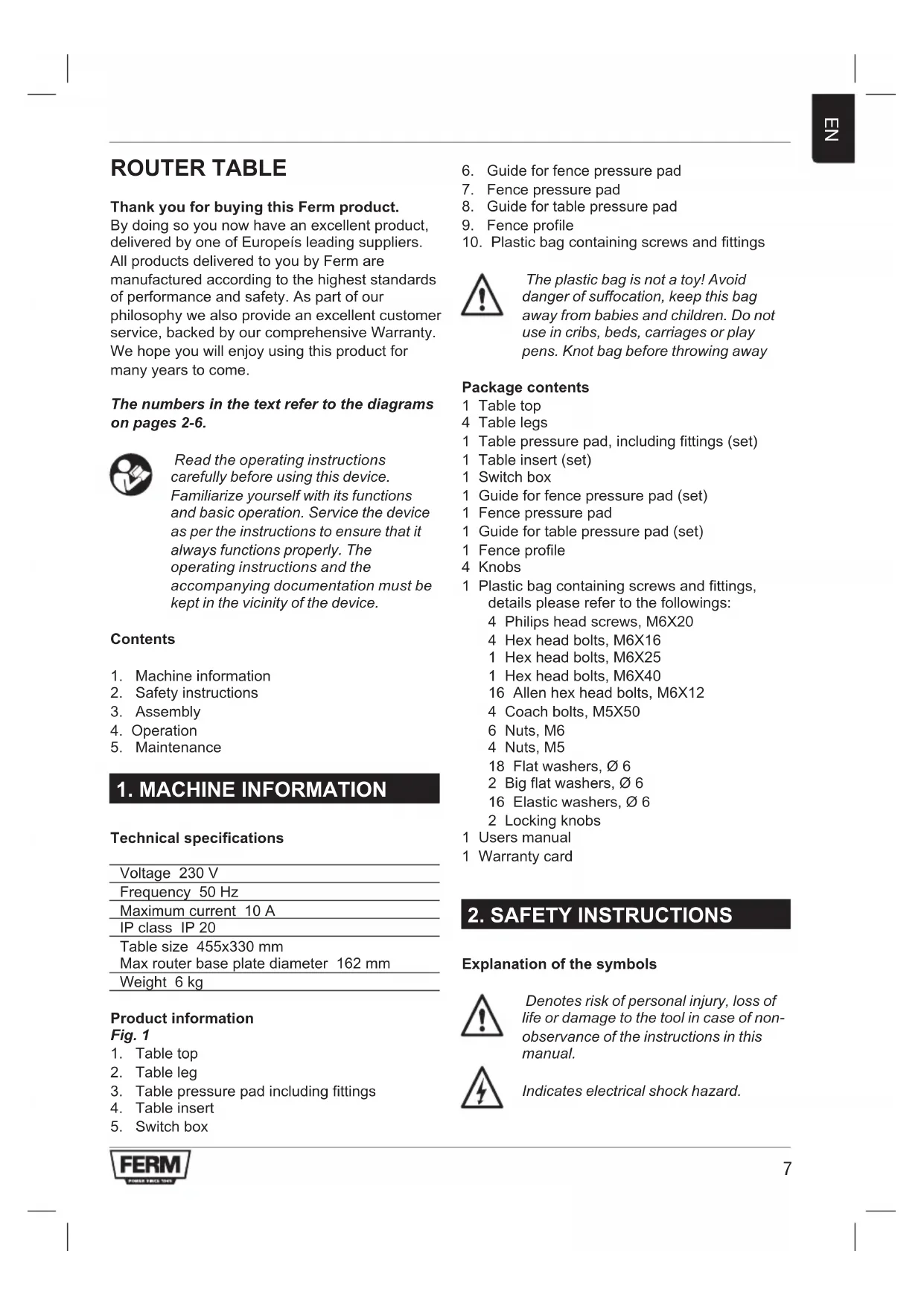
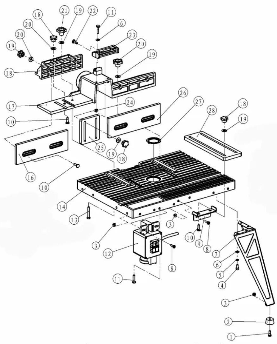
Product information
Fig. 1
- Table top
- Table leg
- Table pressure pad including fittings
- Table insert
-
Switch box
-
Guide for fence pressure pad
- Fence pressure pad
- Guide for table pressure pad
- Fence profile
- Plastic bag containing screws and fittings

The plastic bag is not a toy! Avoid danger of suffocation, keep this bag away from babies and children. Do not use in cribs, beds, carriages or play pens. Knot bag before throwing away
Package contents
1 Table top
4 Table legs
1 Table pressure pad, including fittings (set)
1 Table insert (set)
1 Switch box
1 Guide for fence pressure pad (set)
1 Fence pressure pad
1 Guide for table pressure pad (set)
1 Fence profile
4 Knobs
1 Plastic bag containing screws and fittings, details please refer to the followings:
4 Philips head screws, M6X20
4 Hex head bolts, M6X16
1 Hex head bolts, M6X25
1 Hex head bolts, M6X40
16 Allen hex head bolts, M6X12
4 Coach bolts, M5X50
6 Nuts, M6
4 Nuts, M5
18 Flat washers, 6
2 Big flat washers, 6
16 Elastic washers, 06
2 Locking knobs
1 Users manual
1 Warranty card
2. SAFETY INSTRUCTIONS
Explanation of the symbols

Denotes risk of personal injury, loss of life or damage to the tool in case of non-observation of the instructions in this manual.

Indicates electrical shock hazard.

Danger! Keep hands away from moving parts.

Wear ear protection.

Wear safety glasses.

Wear dust mask.
Additional safety instructions
Safety is a combination of common sense, staying alert and knowing how your router table works.
Read this manual to understand this router table.
Always wear eye protection.
- Noise levels vary widely with location. To avoid possible hearing damage, wear ear plugs or ear muffs when using your router table for long periods of time.
- For dusty operations, wear a dust mask along with safety goggles.
- Follow the instructions in your router owner's manual.
- Warning! Vibrations, caused by the router during use, can cause fasteners to become loose. Before use and periodically during use, check all fasteners to make sure that all are tight and secure.
- Do not use this product until all assembly and installation steps have been completed. Make sure you have read and understand all safety and operational instructions in this manual and the router owner's manual.
- Make sure that the router bit is properly positioned and clamped in the router before making any cuts.
- Do not use the router table as a workbench or work surface. Doing so may damage it, causing it to be unsafe to use. A workbench should be used for this purpose.
- This product is designed for cutting flat workpieces. Do not cut or attempt to cut workpieces. Do not cut or attempt to cut workpieces that are not flat.
- This product is designed for cutting wood workpieces only. Do not use to cut metal or other non-wood materials.
The use of auxiliary in-feed and out-feed supports is strongly recommended when routing long workpieces. Otherwise those
workpieces can cause the route table to tip over.
- Keep hands clear of the router bits and working area.
- Make and use a push stick to move small workpieces across the cutting area.
- Clean the router after use. The use of a wet/dry vac or vacuum equipment is recommended.
Always make sure that work surface of the router table is clean and free from dust, chips, and foreign particles that can interfere with the cut you are going to make. The use of a wet/dry vac or vacuum equipment is recommended. - The fence that comes with the router table has a dust collector to which a wet/dry vac can be attached.
- Check the function of the guard before each use. Remove all dust, chips, and any other foreign particles that can affect its function.
- Warning! Never put your fingers under the overhead guard when the router is plugged into and electrical outlet or when the router bit is rotating.
Always feed the workpiece against the rotation of the cutter or router bit. - Router bits are extremely sharp, be extra careful when handling and using them.
- Make sure that the router bits being used are sharp or have been properly re-sharpened. This will permit fast, efficient, and safe routing.
- Some routers, when positioned in an upside down position (such as on an router table), will drop or fall out of the router base when the base clamp is loosened to adjust height or depth of cut. Therefore, it is extremely important to support the router from below when making these adjustments or whenever the base clamp is loosened.
Always look under the router table at the router switch box when turning the router ON or OFF. Do not touch anything but the switch box when doing this. Never reach under the router table for any reason when the router table is running, except to turn it OFF. - Warning! Before making any cut, make sure the router is turned OFF, the router bit is not rotating, and the power cord is unplugged from the electrical outlet. Then, make absolutely sure that the overhead guard clears the router bit and the workpiece. A trial pass, with the router turned OFF and the router bit not turning, is strongly
recommended.
- Warning! Never leave the router table unattended while the router is running. Turn the router OFF before leaving the router table for any reason.
Electrical safety

Always check that the power supply corresponds to the voltage on the rating plate.
Replacing cables or plugs
Immediately throw away old cables or plugs when they have been replaced by new ones. It is dangerous to insert the plug of a loose cable in the wall outlet.
Using extension cables
Only use an approved extension cable suitable for the power input of the machine. The minimum conductor size is 1.5mm^2 . When using a cable reel always unwind the reel completely.
3. ASSEMBLY
Assembling the router table
Fig. 1 - 13

Before assembling the table, ensure all components are present. In case of shortages please contact the service address on the warranty card.
To assemble your router table, do the following:
- Lay the table top (1, Fig.1) upside down on a flat surface (Fig.2).
- Place a table leg (2, Fig.1) using four hex head bolts (M6X12) and nuts (M6), do not fully tighten yet (Fig.3).
- Repeat the above for the other three legs, and make sure the four legs are on the same flat surface, then tighten all the bolts.
- Once all four legs are securely tightened, turn assembly over, check the table assay does not rock. If any rocking is detected, this must be rectified before continuing by loosening the bolts on the offending leg/legs and adjusting accordingly.
- Insert two coach bolts (M5X50) into holes marked "B" from the top of the table (Fig.4).
- Attach the fence (9, Fig.1), using hex head bolts, washers and knobs supplied. Insert the
bolts from the underside of the table through the holes marked "A" (Fig. 5). Place the fence on the bolts and secure in position with washers and knobs.
Note: Use the graduated scales to line up the fence accurately.
-
Fit the fence pressure pad (7, Fig. 1) by doing the following:
-
Loosen all the fittings on the guide for fence pressure pad (6, Fig. 1).
-
Insert two coach bolt (M6X25) into the holes on the top of guide for fence pressure pad (Fig. 6).
-
Put the guide for fence pressure pad on the top of fence, and align two holes with the two holes on the fence, then insert two bolts (M6X25) into the holes, and secure in position with nuts (Fig. 7).
-
Slide the two front fence, in order to have enough space for fence pressure pad, then put fence pressure pad on the two bolts, and secure it in position with washer and locking knob (Fig. 8 and Fig. 9).
-
Fit table pressure pad (3, Fig. 1) by doing the following:
-
Loosen all the fittings on table pressure pad.
-
Loosen two screws on guide for table pressure pad (8, Fig. 1), and align two hole on guide for table pressure into the two holes on the front side wall on the table, then insert two screws into the holes, secure it in position with nut (Fig. 10).
-
Insert two coach bolts (M6X25) into the hole on guide for table pressure pad, and put table pressure pad on the two bolts, and secure it in position with washer and locking knob (Fig. 11 and Fig. 12)
-
Fit the switch box (5, Fig. 1) by doing the following:
-
Align two holes on switch box into the two holes on the front side wall of table.
- Fit in position with two Phillips head screws inserted from the front of table secured with two nuts (Fig. 13).
Mounting the router
Fig.14-16
Attach the router to the router table by doing the following:
- Loosen the fence securing knobs and slide fence forwards as far as possible, this prevents the router coach bolts (M5X50) from falling through the table when it is turned over.
- Carefully turn the table over and support by it laying it onto suitable sized blocks of wood or similar supportable items. (Fig. 14)
- Place the router in position on the underside of the table as central as possible. Insert two coach bolts into holes marked "C" (Fig. 4) from the table top, now underneath (Fig. 15).
- Loosely secure router in position with the 4 bolts (Fig. 16). It may be necessary to rotate the router in order to locate all 4 bolts correctly. If router is fitted with a speed control, try if possible to position the speed control where it can easily be accessed from the front of the table. Once the router is in the desired position, tighten the 4 bolts sufficiently to prevent the router moving whilst in operation.
- Plug the router plug into the receptacle of the switch box.

This router table only can fit routers with up to 162mm diameter base plate.
- Your router table is now fully assembled and ready for use.
4. OPERATION

When making adjustments etc, always ensure the router is isolated from the main electrical supply by switching off and removing the plug from the socket.
Note: Always refer to the specific router operating instruction manual when making height and speed adjustments etc.
Installing bits
To install bits whilst the router is situated in the table will require the router to be lowered fully. Select desired bit and install. Fit the table insert closest to the size of the bit, ensure the bit does not touch the insert.
Height adjustment
Raise the router until the bit protrudes through the table the required amount. Make test cuts on scrap pieces of wood to set accurately.
Fence adjustment
Loosen the two fence clamping knobs and position the fence as desired, use the graduation marks to set the fence parallel. Make test cuts on scrap pieces of wood to set accurately.
Pressure pad
Set the fence pressure pad to hold the piece of wood flat on the table and against the fence whilst machining. To do this, place the piece of wood against the fence and bellow the relevant pad to be adjusted, loose the two locking knobs and lower the pad until it rests on the wood, push the pad down a little further to apply sufficient pressure to hold the wood flat on the table. Adjust the table feather board in the same manner to hold the wood firmly against the fence.
Jointing fence
Set the jointing fence to support the wood when cutting the full thickness. Adjust the cutting depth etc as previously described, proceed to machine the piece of wood until the lead edge passed over the jointing fence by approx 25mm . Switch off and isolate from the main electrical supply. Hold the wood firmly against the Fence, loosen the jointing fence clamping knob, slide the jointing fence out towards the wood until it touches, tighten the clamping knob. Back the workpiece away from the cutter before switching on again and continuing machining.

As with all power tools, especially those with cutters/blades, keep hands and fingers safety away from blades by using push sticks etc when working on small workpieces.
Dust extraction
Fig. 17
The router table is provided with a dust extraction facility, where a vacuum extractor may be connected to the outlet at the rear of the table, using the adapter supplied. The connection hose requires an inside diameter of 34mm to fit the adapter supplied, the hose, ideally should be a reasonably tight fit on the adapter, which is then just pushed into the hole in the back of the table. Note however, that this does not preclude the
user from wearing a face mask to prevent the inhalation of dust particles.
5. MAINTENANCE

When carrying out maintenance etc, always ensure the router is isolated from the main electrical supply by switching off and removing the plug from the socket.
The machine has been designed to operate over a long period of time with a minimum of maintenance. Continuous satisfactory operation depends upon proper machine care and regular cleaning.
Cleaning
Keep the ventilation slots of the machine clean to prevent overheating of the engine. Regularly clean the machine housing with a soft cloth, preferably after each use. Keep the ventilation slots free from dust and dirt. If the dirt does not come off use a soft cloth moistened with soapy water. Never use solvents such as petrol, alcohol, ammonia water, etc. These solvents may damage the plastic parts.
Lubrication
This machine needs no additional lubrication.
Faults
Should a fault occur, e.g. after wear of a part, please contact the service address on the warranty card. In the back of this manual you find an exploded view showing the parts that can be ordered.
Environment
To prevent damage during transport, the appliance is delivered in a solid packaging which consists largely of reusable material. Therefore please make use of options for recycling the packaging.
Warranty
For the conditions of warranty, please refer to the separately provided warranty card.
FRÄSTISCH
Specifications techniques
Tension 230 V~
Fréquence 50 Hz
Courant nominal 10 A
Classe IP IP 20
MOrTy NIOBnIaTb Ha eepaBoTy.
- PpeDynpexKdHne! HkOrda He BcTaBnIte NaIbCuI NOd BepXHIO 3aunTy, KOrda fpe3epHbI CTaHOK BKnHoueH B CeTb IIN npi BpaUeHNn fpe3bl.
- POnaBaIe DeTaJIb BCerDa npOTnB HApRaBHeHnB BpaUeHnA Fpe3epyUoSei HaDCTaBKn.
3y6bpaepesbOeHbOcTpble,no3TOMy npn 6baueHHN C HMMN INpN INX NCIOJIb3OBAHIN 6yDbTe OeHb BHIMATEJIbHbl. - PpOBepbTe, YTO nCnONb3yEmbIe 0cTpbI IN npaBnJIbHO 3aTOHeHbl. 3TO N03BOJNT npoN3BeCTn pa6Otbl 6bICTpo, aΦΦeKTHBHO n 6e3ONaCHO.
- HekoTopbIe 0pe3bl, KOrda OHn HaxoJrTcB NpepeBepHytOM NOIOKeHN (HaNP. Ha CTone CTAHka), MOryT yNactu NN BbInactb N3 NOCTaBKN Ope3bl, KOrda MyOta NoCDTaBKN 6ydt Ocna6bNeHa dNp YcTaHOBKn BBICOTbl NN rIy6bHb pe3a. OueHb BaXHo npi PPOBeDEHN DaHHo peRyINIpOBKn NOdEprKaTb 0pe3y cHn3y BO BpEma Ocna6JIeHNA KpeJIeHNA MyOfTbI NOcTaNK.
- PnB BkHIOUeHm HIN BbIKHIOUeHm CTAHka BCerDa nocMOTpnte NOc cTOn fpe3bl Ha 6IOK BkHIOUeHn. He npKacaiTeCb npn 3Tom K Hn Yemy dpyromy 3a NCKHIOUeHnem 6Ioka BkHIOUeHn. HnkOrda He MaHInynpuYte NOd CTOLOM BO BpEmpa60tbl fpe3bl 3a NCKHIOUeHnEM Oepaunn BBKHIOUeHn.
-Преунгдени!пелдингдени Юбогу pe3a y6eintecb,yTO φpe3a Выкючehа,надстаьк aфpe3bl He ВрашaeТСЯ BИЛКа StHypa ПИТаня He НхODITcB pO3etke.Посе 3TORO y6eINTcB,yTO Верхнй кoxуx HaxODITcR Ha 6e3ОпАСHOMpacCTОHnOTHaDCTABKN Фрe3bl 3aIOTOBK.N.PekOMeHdYEM Пpon3BecTN pNo6HyIO NOdauPy prN ВыкючEHHom CTaHKe n OCTaHOВЛeHHoH HAclTAbKeФрe3bl. - PpeDynpexKdEHe! HnKOrDa He ocTaBnIe CToI Φpe3bI 6e3 npncMOtpa BO BpeMpa60TbI cTahKa. IpePd yXoOM OT cTOna cTahKa nO JIO6oBn npuHHe BbIKNIOUHTe fpe3epHbI cTahOK.
3neKtpnuecka 6e3onacHocTb

Bceeda npoeepbme, ymo numaHue coomeemcmeyem HanpXeHuO Ha munoeo ma6nueke.
3aMeHa Ka6eJeu JIn BnOK
Бe3 npOMEДпЕнЯ ВьбрасьВаиТе CTapbie Ka6eJIИ ИИ BUNI KIN NOCNE INX 3aMeHbI HOBbIMN. OnacHO BCTABnTb BUNKy HEnoDKNIOueHHORO Ka6eJIBA pO3eTKy.
IcnoJb3OBAHHe ydJIHHTeJIbHbIX Ka6eJeI.
IcnoJIb3yIte TOnIbKO yTBePxDiEHHbIe
yIINHInTeJIbHbIe Ka6eJIa, COOTBeTCTByIOUcne
NOrpe6JIeMoI MOuHOCTn CTaHka. MInHMaJIbHoE
ceHeHne Ka6eJIa CoCTaBnIeT 1,5 MM. Ppi
IcNoJIb3OBAHn Ka6eJIbHOJ KAtyUKN NOnHOCTbIO
packpyTIte eE.
3. MOHTAX
MOHTAX cToJa 0pe3epHoro cTaHka
Puc. 1 - 13

Ipeod c6bokou cmona y6edumecb, umo 8 haunuuu umekomc 8ce demaru. Ecnu kakue-nubo demanu omycmeyiom, c8xkumecb cepeuchbim uehmpom no appecy, npubeedeHHOMy e zapaHmuHOM nucme.
Pn c6opke cToJa fpe3epHoro cTaHka DeiCTByIte CJIeDyUOuIM O6pa3OM:
-ПолбкTe BepxHIOU qactb CTOna (1, pnc. 1)ВпереврHyTOM NOLOXKeHn Ha poBHyTOBepxHocTb (pnc.2).
3akpenTe hory cToJa (2, pnc. 1) npn NOMOuN YeTbipEx 6oNTOB C ueCTnrgpaHHOI roJIOBko (M6x12) n raeK (M6), Ho eue He 3axImaTe ee (pnc. 3).
- IOBTOPHTe npINBeHHyIO OepaunHO dIyOCTaJIbHbIX TpEX Hor, pOBepbTe, yTO6bl HOrN 6blN B ODHOI NIOCKOCTN. IocNe 3TOrO 3axMITE BCE 60JITbl.
-Послесзakpenlenя BCex YeTbipEx Hor nobepnTe co6paHbI y3eI n npOBepbTe ycToiYNBOCTb CTOna.EcIn cToI HeycToiYNB, To nepeI dAnbHeuWein cbOpKo ChOBA OTNyCTIte 60NTbI Ha Heo6xOIMoH ORe I OTperyIpPyTe ycToiYNBOCTb.
BIOXInTe DbA 6oTtAc KBaIpaTHbIM NOrONoBcOM (M5x50) CBepxv B cToI B OTBepCTnC o6o3HaueHneM "B" (pnc.4).
-ПрипnomоибОБТOBc WecTnRpaHNoI roJIOBkoI,шaIbИЗЖIMOB 3akpeNITe orpaXdEHe(9,pnc.1).BoNTbI BINOxNITe CHN3y cToJa YpeE3 OTBepCTnA C
063HaueHnem "A" (pnc. 5). OrpaJdeHne yCTaHOBNTe Ha 6oNTbI n 3aФнКcnpyTe erO IIOJOKeHne 7aN6amn n 3aXIMAMn.
PIM.:IJI ToHoro BbipaBnBaHnOrpOpaKdEHHNcNoJb3yTe yrnomep.
HacaIte npKIMHyIO nAHeJIb (7, pnc. 1) CNeDyUOUM CNOCOBOM:
-
Omnycmmuge ecio cyphumypy ha nnapa8npoueu dno npuxkumho naheu opaekdeHua (6, puc. 1).
-
BcmaBme dea 6onma c KeadpamHbIM nOdozoOBekom (M6x25) e omEepcmua 6eepxy hnpabnnoe du npuxumho naHenu oepkdenu (puc.6).
Hacadume HapnaeJouyO npuxumno naneu Ha cepxHIO yacmb ozaepdeu u cpaehme dea omepcmua c dyma omepcmu ozaepdeuu, noce 3mo2o ecmaebme dea boma (M6x25) omeepcmua u 3afukcupye ux noJoxHeue bomamu (puc.7).
CdbuHme dba nepedhux ozaekdehna maK, ymo6bI bIno docmamoyno mecma dnn npuxumho naHeNu ozaekdehura, nocne 3mo2o hacadume npuxumhyo naHb ozaekdehura Ha dea 6onma u 3aФukcupyime noLoxKeHue wau6amu u pfukcupkyoumu 3axumamu (puc.8 u puc.9).
HacaIte npKIMHyo naHeIb cToJa (3, pnc. 1) cneDyUOuM o6pa3OM:
- Omnyc模糊 ece kpenlenu Ha npuxumHou nHaenu cmona.
-
Omnyc模糊deaa6bmonaHa Hanpaenloue dna npuxumno naheu cmona8,puc.1)u bipoohme dea omepcmua Hapaeiaoue dna npuxumno naheu cmoa c deyma omepcmmu Ha nepeodneu 6okobu cmehke cmona, noce 3mo2o bnoxume o omepcmua dea 6bmona u noloxene 3afoekcupyume aukou (puc.10).
Bnoxume dea 6oMa c KeaopamHbIM nOdoNIOBcKOM (M6x25) e omepcmua Ha Hanpaenlouwe dnn npuxumHOu naHenu cmona u Hacadume Ha Hux npuxumHyu naHelen cbmona. PonoKeHue 3aФukcupyime wau6amu u npedoxpahumelhbuMu 3axumamu (puC. 11 u puc. 12) -
UctaHOBnTe KOp6ky BbIKNoHateJra (5, pnc. 1) CNeDyUoIIM o6pa3OM:
Bbipo8nme 3ea omepcmna Ha Kopob6ke bkiIouamena C omepcmma U nepehdue bokobou cmehke cmona.
Bnokume oomepmua dea kpcmoebix 6onma - cnepeu cmona - u zauukcupyme ux deymzaukamu (puc.13).
MOHTax 0pe3bl
Puc. 14-16
3akpenTe 9pe3y Ha cToJe cIeDyUOUM o6pa3oM:
OTnyCTnTe 3axmbl, ydepKINBaHouune OrpaxdEHeN u npeDbHbTe eTo KaK MOxHO daNbWe Bnepdd; 3TO npedOTBpaTIT BbnaDeHne 6oTob C KBaPaTHbIM NOIroNoBkOM fpe3bl (M5x50) n3 cTOna, KOrda cTOn 6ydet nepeBepHyT.
- Octopoxho nepeBepHnTe cToI n noJoxHte ero Ha 60nbue 6pyckn nn anaHOrnHbIe onopbl (pnc.14)
- Hacadnte 6pe3y cHn3y cToJa KaK MoKHO ToUHee nO ueHTpy. B OTBepCTnA C 6o3HaueHnEm "C" CBepxv BCTaBBTe DBA 6oNTa C KBaDpaTHbIM NOIroNOBkOM (pnc.4), a Nocne 3TOrO cHn3y (pnc.15).
Cbo6oHNO 3aΦnKcnpyIte Φpe3y YeTbipbMg BoNTamn (pnc.16).Pn3OM BO3MOxHO npndetcnpOBepHyTB Φpe3y dIra TOrO, UTO6bI BCE 60NTbI cenn npabnIbHO.Ecnn Fpe3a IMeET ynpabNeHne CKOpocTbIO, NOnblTaIeTcB erO yCTaHOBtB B MecTe, rDe OHO 6ydet JERKO DOCTynHO CnepeDi CTOna. Pocne yCTaHOBKn Fpe3bIB Tpe6yEmoe NOLOXHeHne C DOCTaTOUHO CNIOI 3aXMITE qETbIpe 60NTa dIpy npeDoTbpaueHn IAINXeHnA Fpe3bI BO BPEMa pa60tbl.
BCTaBbTe Bnky fpe3bI B pa3bEm 6noka BKJIIOUeHnR.

DanHbIΦpe3epHbI cmaHOK npedHa3nauen dnyΦpe3 c duamempom nocadoouho naHenu do 162 MM.
- Pocne 3Toro BaHa nactoBnae ppe3a noHocTBIO CO6paHa n roTOBa K 3KcNpyatau.
4. 3KcπJyATAUЯ

Ipu pezynupo6ke u m.n. 6ce2da obecneybme, ymo6bl fpe3a 6bila omKlnoyeHa om 3neKmpocemu biknoueHuem u bimra2uhaueM 8unku u3 cemeoP0emku.
IPM.: Pn peRyJInPOBKe BbICOTbI, yCTaHOBKe CKOpOCTn n T.I. BcERdAn PnpIePKNBaIte KOHKpeTHbIX yKa3aHn INHCTpyKcIMN K HAcTOnbHoI φpe3e.
YCTaHOBka pa6OuNX HAdCTaBOK
PerynipOBKa BbICoTbi
YCTAHOBNTe 6pe3y B NOJIOKeHne, KOrda
HaDCTABKa BbICTynae T HAd CToIOM Ha Tpe6yeMyo
BbICOTy. Ha Kycke DpeBeCINbI PpON3BeDITe
PpO6HbI pe3 dIg TOUHO peryNIpOBKn.
Peynpobka orpaekdeHn
Otnyctnte Dba 3aЖиma, ydepknBaHoune
orpaxdene n OTPeynpuye ero no
Heo6xOIMocTn.ДЯ napanpeIbHOJ
peryIpOBKn OpraxdeneHn IcNoJIb3yIte MeTKn
pacCToHnHa KysCe IpeBecnHb npOn3BeDInTe
PpOBhI pe3 dIpyToHo peryIpOBKn.
PnXmHa nHeJIb
YcTaHOBnTe npJxHmHyI naHeJIb orpaXdEHHa TaKIM O6pa3OM, YTO6bl Iprn O6pa6OTke OHa IIOndePKuBaIa DpeBecnHy Ha CTone B IIIOCKOM IIOJoxEHnN K ORpaXdEHHo. JINr 3TOrO IIOJoxHTe KUCOK DpeBecnHbIK ORpaXdEHHo H NOD peryInpyEmyIO naHeJIb, OTnyCTnte Dba IKCnpyUOxN 3axkMa n OTnyCTnte naHeJIb DO KacAHnA DpeBecnHb.I Pocne 3TOrO naHeJIe Eue npIXMnTE BHN3 TAK, YTO6bl OHa npIXMmaIa DpeBecnHy K CTony. HAcToPiTe naHeJIb Ctona aHaNoRnHbIM CnOCo6OM, YTO6bl OHa IpoUHO npIXMmaIa DpeBecnHy K ORpaXdEHHo.
MOnTnpyemoe orpaxdHeHne
YcTaHOBHTe MoHTnpyEmoe orpaXdHne IJIa POnDepKKn DpeBecnHb npn pe3Ke no Bcei
TOJIUHHe. YCTaHOBInTe rIy6nHy pe3a n T.D., KAK OINcAHO BblIe n IepemeuaIte KycOK dpeBeCInbIB CTAHKe, NOKa IpeEHNr IpaHb IpeEiET MOHTpyEmoe ORpaxDeHne np6Ih. Ha 25 MM. BblKIOuHTe CTahOK n OTcoEINHInTe OT cETn. IpOuHn PnIXMnTE DepeBO K OrpaxKeHnIO, OTNcyTNe 3aXIM MOHTpyEMOro ORpaxKeHnR, IpeMeCTNe ORpaxKeHne B HAnpaBNeHn K dpeBeCInHe Do KOHTaTa n 3aXmTe 3aXm. IpeEe BKIIouHeHem CTAHka n IpoDoJxKeHem o6pa60Kn DoCTaHbTe 3aROTOBky n3 CTAHKa.

Kak u dne cex 3nekmpuueckux
uhcmpymno, npexde ecezo C
pezamu u HOxamu, npu pafo me C
MaIbIMU demaIamu He npubnkaum
PnbUpU pyku K HOxam U u
ucnonb3yme dna nodaqu peuku.
33BbITJXKa nbJn
Puc. 17
Φpe3epHbI CTaHOK IMeET yCTPOINCTBO dIa BbITJIKN PbIIN. K Eero BbIBody c3aIIN CTOna MOxH0 IODCOeHNHTb BbITJKKy C pa3pIXeHnEM. IcNoJIb3yIte npIInaraembl aIaNTep. IoDCoeHNReMa Tpy6ka DoJXHa IMeTb BHyTpEHnI DnAmEtp 34 MM dIra TORO, YTO6bl COOTBETCTBOBaJa NOCTABLNeMOMy aIaNTepy. B IDeaJIbHOM Cnyae OHa DOJXHa NIOTHO CNDetb Ha aIaNTpe Nocne BCTaBJIeHnB OTBepCTne Ha 3aIHei CTOpOHe CTAHKa. Ppi 3TOM NOMHtE, YTO onepaTop 063aTeINbHO DOJXKeH NcONb3OBaTB peCnnpaTop dIЯ npeDToBpaUeHnBdbIXaHnY qactuI pblII.
5. TEXHnueCKOE OBCJIyXnBAHne

Ipu mexHuuecKOM o6cnyXueaHuu u m.n. 0ce2da o6ecneyme, ymo6bl fpe3a 6bila omKnIOUeHa om 3JIekmpocemu 8bIKNIOUeHuEM u 8bImraueaHuem BUNku u3 cemeoU po3emku.
CTaHOK npedHa3NaueH dIy dIInTeIbHOJ 3KcNpyatauC MmHMaJIbHbIM yXoDM. PpOIOJIxNTeJIbHaJ haIeXHaJ pa6Toa 3aBnCtOT npabINbHOro yXoJa n peryIpaHoi OUNCTKI cTaNka.
OuicTka
BeHTnIaONHbIe ⅢeJI nCTaHka DoJXHbI 6bITb
YnCTbIMn DnI npedOTBpaueHnnepeBa
DbIraTeJI. PeryIaRHO OunuAte KoxyN CTaHKa
MMyKoI TKAhBIO, npexKe Bcero NocJe KaKDoRo
NCNoIb3OBAHn. BeHTnIaONHbIe OTBepCTnIa
DOJXHbI 6bITb 6e3 NbIiN 3aRpy3HeHn. EcII
3aRpy3HeHn ydaJIntb HeBO3MOxHO, IcNoJIb3yInTe
MMyKUo TKAhB, CMOyeHHyO B MblHoN BOe.
HnkOrJa He IcNoJIb3yIne pactBopnteIN - 6eH3nH,
CnIPT, UeIoCHyIO BODY, T.K. OHN MOrYT NOBpeDNTb
PnactMACCOBbie DeTaN.
Cma3ka
YcTPOINCTBO He Tpe6yeT DOONHHTeJbHOm Cma3Kn.
HencnpaBHOCTN
B cnyae obhapykeHn HeucnpaBHOCTN, Hanp. n3-3a u3HOca DeTani, o6paTntecb B cepBnCHyU cnyk6y no aDpeCy, npuBeDeHHOMy B rapaHTnHOM IncTe. Ha 3aJHei CTOPOHe DaHHoI INHCTpyKcnn pInBedeH pUCyHOK C yKa3aHHeM dTeTanei, KOToPbIe MOxH0 3aKa3aTb.
Cpea
BCTAHOBITb BMnKaay 3anaIIOBaHHa (5, 306p. 1) TaK:
BupieHnme dea omepu Ha emukaqi 3anaHouanHa omeopamu Ha nepeHiu 6okoi cihi cmony.
Bknaimbyomepu dea 2eunmu 3 xpecmoBuHO y HnprMky cnepey cmony i 3aikcyume ix deoma 2aukamu (3o6p.13).
MOnTaXΦpe3n
3 06p.14-16
BctaHOBiBΦpe3yHa ctiI:
Bidnyctitb peryntopn, kotpi TpmaoTb oropodxeHHi Biccyhthe ykomora daJI Bnepei; ce He Do3BOHnTB BOpITHM rBuHTam fpe3n (M5X50) Bnactn i3 cToIy, konn cIn nepeknHyto.
- OБерекно посякньтстл i noknapitb noro
Ha BiДповідно Велникkoю n aбо к ha
noDi6Hi niДnopn (3o6p. 14)
BcTaHOBiTbΦpe3y 3Hn3y niD cToJOM kOMORA ToHiiue y cepeiHy. Y OTBOpN 3No3HaUkAMN "C" BKnadITb 3BepxY cToIy DBA BopiTHI TBnHTn (3o6p. Notim 3Hn3y (4, 3o6p. 15)
Binbno 3aΦikcynte Φpe3y YoTPMa rBnHTamn (3o6p.16).MoKe BnHKHyTn nOtpBa 3nerKa nobepHytn Φpe3y, uo6 yci YoTnpu rBnHTn npabInbHo ciIN. KaUo Φpe3y o6naHaHO dIe KepyBaHHra WbNdkicTHO, To MoXHa BCTaHOBtnpereynLio WBnKocTi TaM, De BOHa 6ynde IerKO DocTyHNO CnepeSy CTOny. BCTaHOBwHn Φpe3y y Heo6xidy No3nCiIO 3aTgHITb DoCTaTHbO yci YoTnpu rBnHTn, 0o6 3anobirtn NocyBaHHIO Φpe3n NiJ hac pOBtN.
3acyhBTe BnIKy fpe3ny po3eTKy BMnKaa3anaJIIOBaHH.

Lio bepcmamHy ppe3 npu3haeHo minbku dla ppe3 3 diamempom OchoBHOIO nIacMuHu do 162 MM.
- Tenep Bauly BepctaTHy pfpezy cknaJeHo i niIroToBaHO do ekcnnyatauii.
4. EKCIJIYATAUJIA

Bukohyouu Hana20xueaHn i mn. Cnid 3abe3neumu, uo6 ppe3y byno eiknoeHO bi eIekmpuHzo kueHH, Eumkhymo i eunky BumraHeHO 3 po3emku.
PpM.: PeryIIOUCh BUCOTy, HanaIooKyoUOu IWBnDkictb i T.., CIId dIaTn 3aBXKn 3rIHO 3 KOHKpeTHmN Bka3iBkAm y iHCTpyKciI Do 3aCTocyBaHHaΦpe3n.
BcTaHOBneHHpo6OuH hacaDOK.
Дя BCTaHOBJIeHHЯpo6OuHX HacAOK KOI
Фpe3a 3HaxoJITbcraHa cTOni, cIiD φpe3y
NobHicTIO onycNTi. Bn6epiTB Heo6xIDHy
HacaIKy i BCTaHOBITb II. BCTaHOBITb BKnaDKy
CTOJy, JAKOROMORA 6JIbIe BiINOBiHy Do PO3Mipy HacaKn TAK, Uo6 HacaKa He TopKaJaacr BKJaKn.
PeryIIOBaHHBnCOTN.
IiHimaTeΦpe3y,doKn HacaKa He 6ynde CTnpaTn Hnd CToJOM Ha Heo6xDiHni BucOTi. 3a BVkOpncTaHHm BiDpi3ky DepeBa 3po6iTb np6Hn p03pi3 DnA TOHOro HanaRoDxKeHH.
HaIarodXeHH orOpOxKeHH.
BiDnyctiB DbI KHOKNK, kI npITpMHyOTb
OropOJxHHe i HanaRoDiTb Ioro Jk Heo6xIdNo.
Ina napaneIbHoro HanaRoJxHeHHr OropOJxHeHH
cIid cKOpNCtAtnca MIPKaMn BiJaJI. 3a
BnKOpNCTAHm BIDpi3ky DepeBa 3po6iTb
Ipo6Hn po3pi3 dIy ToHoro HanaRoJxHeHH.
PnTnCKHa nJaCTnHa
BctaHOBIb npntnckHy nlaCTHy oropodKeHHa Ta, 06 niD qac pObotn BOHa npTpIMyBaNA
WMaTOK DepeBa Ha cToI y IexaCyOM noIOXeHHi Ta npOTn oropodKeHHIO. Dna zBoO noklaIDtB
WMaTOK DepeBa HABPOTN oropodKeHHa Ta NiD BiINOBiDNy PnactHy, KOTpy Tpe6a
BiDperynBOATN, BiNcyTtB DBA fikcyuoyi
peYrAToPi cnyckaTe PnactHy, DOKN BOHa
He JExKaTmE Ha DepeBi. Notim PnactHy ue
npTnCHITb yHn3, 06 BoHa DiyraHa Ha DepeBO 3
npTnCKHM 3ycnnlMn NO BiHOweHHIO do CToJy.
BiDperynTe Tak camo dOwky CToJy, 06
BOHa MIcHo npNTpIMyBaNA DepeBO HABNPOTN
oropodKeHHIO.
36iphe oropodkeHH.
BidperyIIOte 36ipHe oropOJKeHHa, KOtpMaepnptpIMyBaTn DepeBO nID yac nopizy zuoioTOBUnHn. Hanarodmbu rNbHy npop3y TaIHue, kONcaHO Bnue, nocyBaTe UMaToK yBepCTaI DOkNepeDnE pe6po He BnIe Ype336ipHe oropOJKeHHa pni6n3Ho Ha 25 MM.BiMKnHtB BepCTa I BiKlIOUHTB Bd KINBJeHHa.MiNo nprtpmaite DepeBO HABnpOTn oropOJKeHHIO, BiDnyCITb IKCYIOuH peryJrTop 36ipHoro oropOJKeHHa, 3MICTb oropOJKeHHaY HApRMky Do DepeBA, DOK BOHN HeTOPKaTMyTbcra 3aTaRHiB IKCyIOuH peryJrTop.PepH hIX 3HOBy VBIMKHyTN BepCTa I noOHHaTIPO6OtY, BVITRtB obo6JIIOBaHy Detanb i3Φpe3n.

Iyecix enekmuhux
incmpymehmie,oc6nueo y mux,aki
MaombHOxippe3u,He cnid niO qac
po6omu 3 Manumu umamkamu
Ha6nukamu nanbu ma pyku do HOxie,
dnnpocyaHn demaneu mpe6a
kopucmyamcna nuqmu.
Bntjka npoxy
3o6p.17
BepctaHy pfpe3y 6bnaHaHO arperatom dny BnTjKnn npoxy TaM, De moXha Do BVBOdy y CTiHi npEiHaTu BakyUHMy BnTjKky, cnId cKOpNCtataNc npKNaIeHm aadantepom. UlaHr DnI npEiDaHnry MyCtB MaTN BHyTpiiHni diAmtp 34 MM, 0o6 Bin BiNobiAb aadantepoBi. Y iDeaHbHomy BnauKy UJaNr MaE, nicra BCTaHOBHeHH B OTBip y 3aHni qactnHi cToNy, MiHo CnDITn Ha aadantepi. OdHae cIid nam'YaTAtn, 0o ce He No36abIe KOpNCtByaHa Heo6xIDNoCTi HocHTn 3axnchy Macky, 0o6 3aNo6iTn BdxxAHHIO npoxy.
5. NOTOUHNI PEMOHT

BukohyuHn Hana2OJyEaHHma iHwi
po6omu, cnid 3a6e3neumu, uo6
fpe3y byno eiknueho eid
eNeKmpuHNO xueHeHH, EumKhymo i
bunky umr2HeHO 3 po3emku.
Bepctat ckOHCTpyNoBaHO TaK, 06 BiH Mir npaIOBAtN DOBrn Yac, He BIMaraIOUHy HIXKO rnoTOouHOro peMOHTy. TpBaIa 3aOBIbHa po6ota 3aJIeXuMbBiD pRaBnIbHOrO yTpIMyBaHHr BepCTaTy Ta Ioro perynapHOrO uIeHHra.
UH
Utpmyte BENTnlaiHi ⅢIINH BepctaTy
YnCTHMN, 063anO6irTu HAdMipHomy HarpiBaHHIO
DBnryHa.PeryIpyHO uCTITb KOpynCn BepcTaTy
M'AKoIO raHupKOIO, 3OKPema nICr NKOHO
3AcTOcyBaHN. YtpmyTe BENTnlaiHi
IzINH 6e3 npoxy Ta 6pydy. JKIO HeuNcTOn
He MOxHA yCyHyTN, CkOpNCtauTEcR M'AKOIO
raHupKOIO, 3MoueHO IO y MInbHI BODi. HIKOI
He KOpNCtuyTEcR po3UnHHNKamn, TAKIMN JK
6EH3IN, cnpT, amiaHa BOda, ToIO, kI MoRN 6
NoWKoDHTN PnaCTNKOBi Detani.
3Ma3yBaHHa
LcBepCTaT He Bumarae HiaKoro DoTaKOBoro 3Ma3yBaHH.
3aBau
PnBHNKHeHHI NOxKOJKeHHa, HApNKaIad, y
HacNIOK 3HOuYBaHHaDeTaNeI, cNlD 3BePHyTncy CepBicHNIeHTp, aDpeCy kKoRO Bka3aHO y
rapaHTiHOMy TaNOHi. Ha octAHHI cToPiHci Ucici
InCTpyKciBn 3HaJeTe po3KnaJeHe 3O6paXeHHa
DeTaNeI, KI MoKHa 3AMOBHTn.
Cepedobuie
Iio6 3ano6irtn nookdokeHHIO nID qac TpaHcnpTy, Bnpi6 noctaaybcsy TBepdomy naKybaHHi, KOtpe NOBHCIO CKnaDaETbc3 MaTepiAnB, kki MOxHa 3HOBy 3actocyBaTN. Tomy cnId cKopncTaTNCRAoXNBOCTaMn yTuNi3aui naKybaHHJ.
Tapaantir
IIO do yMOB rapaHTii DnB. OKpeMo npNKJaDeHn I rapaHTiHn TanoH.
ENITPANEZIAΦPEZA
ZaEUXApIOToUe Tou EIIeGaTe va ayopaoTe auto To Tpoiov Tns Ferm.
TwaPiEvdiAeTeEvaEgApetiko
Tpoiov, kataoKeuaOevo aTo evav aTo touc
eYalutepouc TPOUmTheuTEc TnEupWntn.
Oa Ta TPOIOvTA TPOUmTheueote aTo tn Ferm
kataoKeuacovta OUMwva Me ta Uynlatopea
Tpotua aTIOdoanKai aQaAeiac. epos
TNS φIoOoPiaC Ma, TAPexoue EtniOns apiotn
EcutnpETnoN TEaIwv, uuvodeuOeVn aTo tnV
TAnpN EvyUnon Ma.
Eaizoue 01 Oa eivete Euxapiaotnevoi aTo n Xpnoan autou Tou Tpoiovtoc ia TOnA xpvia.
Oi apioi nou npieoxovra oTo keiuevo avapoeovra oTa diaypauata, nou unapxouv 01c 0e i6 2-6.

Piv tn xpon tnS ouakeunc diaaote AITTOpeia Tn napov odnyies
xponc. Evnpomegaitee TIC
AEIOUpyiec kai tn baoikn EGUINpETnoN.
Xeiipoteire tn ouakeun navta oupwva TIS ONDyics, vaeaaopalote n owotn
AEIOUpyIKOTnra TNS. OI ONDyEc XPOANCS
kAI TO OUVODeuOevo TeXVIKO Eyypa0
PepTeVa Bpioketai PAnoiov Tns
ouakeunc.
περιεχόμενα
120g 210g (40 g) 120g 120g
(a) y = 0 jollll boloool
aljala baii ooi
(a) ( a + b) = 10 + 10 - 1
S OBC = S COD + S_ BOC
4
s
- 12 1. 12
20X6M Philips 4
16X6M Jaa aai 4
25X6M
40X6M
12X6M J. Allen 16
50X5M
5M·6M 4.6
6 jia:aiwu 18
6 jbi jia buaa jy k jy
6 16
Jia li
S APQ = S AQP + S_ PQR
a21, jlaa 8by
alwll caijai.2
i 1
128 62jll clalil 1y po 10
山
jss


1
A. a_i all i = 1,2,·s ,s
Jell E L


aaiyaiy
Jae aiee ae jaoa eaiy g ooi y poal yoe aee aed
a aai i 1iia aie ai ie ai
Jaaal eab aay aaiy Jaa Jaa 2. Jaaal eab aay aai
aabaa 25
aaii i 1 aie aiee
aill yie 1gall jooy jolal
y
aJaaal gba 1y, Abygall aal gaaagaa
Say
Jaaal gblia, yill pae yll
y 5 yall Jaal l aai I gnnn n
Jaeill Aobio
iisill siiw y iisil ay
aaiiie
oJg jy 1 yj 1 1 1 1 1 1 1 1 1 1 1
J 1
iill 1y. y. lao jai gill bll c
aill aill
jell jie jie jie jie jie jie jie jie jie jie jie jie jie jie jie jie jie jie jie jie jie jie jie jie jie jie jie jie jie jie jie jie jie jie jie
A
y j 1s all jy p a. aldo s J s jg jn
y
ALoc
Laiie gai jil gai jil gai jil gai jil gai jil
aai j 1
1
e 1
.
Lae Jaleill iie yall jaii gii daiyall aiai ai
logistic
Jalla laa aol 1 p jol sall aolll al j no gai
jol lal, jol all ydlil ydlil ydlil
L) 10000000000000000000000000000000000000000000000000000000000000000000000000000000000000000000000000000
auiy
Jaaal 1000000000000000000000000000000000000000000000000000

gai jyLs1
JyLioie aagai gai gai j 1000000000000000000000000000000000000000000000000000
#
aal l y aulll, sallll llal 1y S y prn 2
s y plaiiie 1ie .p001 yall waeid ylll. aySall
Lls kss sll
.3
#
13-1
J 1 J

:la Jaa aiaaia
(2K) 1 (1K,1) 15
yolue a jy 1 (1K,2) 15 yS
Lbji (6M) Jy 12X6M w0 (3 K) 4y
gj yj yj yj yj yj yj
JbI JbI JbI JbI JbI JbI JbI JbI JbI JbI JbI JbI JbI JbI JbI JbI JbI JbI JbI JbI JbI JbI JbI JbI JbI JbI JbI JbI JbI JbI JbI JbI JbI JbI J bJI 150X5M 150X5M 150X5M 150X5M 150X5M 150X5M 150X5M 150X5M 150X5M 150X5M 150X5M 150X5M 150X5M 150X5M 150X5M 24 (4)
jall 1511 jall jll plal
la Jus j1 (1 7) jall bia sow,
15 25X6M wao jy Jaa 6
(6Jall) jalal bia sll aag yai jy gall
jajlall jalal bia sll aag yai jy gall
jay jay jay jay jay jay jay jay jay jay jay jay jay jay jay jay jay jay jay jay jay jay jay jay jay jay jay jay jay jay jay jay jay jay jay jay jay jay jay jay jay jay jay jay jay jay jay jay jay jay jay
JyL Jx Jx Jx Jx Jx Jx Jx Jx Jx Jx Jx Jx Jx Jx Jx Jx Jx Jx Jx Jx Jx Jx Jx Jx Jx Jx Jx Jx Jx Jx Jx Jx Jx Jx Jx Jx Jx Jx Jx Jx Jx Jx Jx Jx Jx Jx Jx Jx Jx Jx JXJXJXJXJXJXJXJXJXJXJXJXJXJXJXJXJXJXJXJXJXJXJXJXJXJXJXJXJXJXJXJXJXJXJXJXJXJXJXJXJXJXJXJXJXJXJXJXJXJXJX
162 1

jaiia jaii jia gao yjia jia jia jia jia jia jia jia jia jia jia jia jia jia jia jia jia jia jia jia jia jia jia jia jia jia jia jia jia jia jia jia jia jia jia jia jia jia jia jia jia jia
biinai sLw g
Jy 11111111111111111111111111111111111111111111111
by jda
No. Description Position
| 400750 Leg complete 1 till 7 |
| 400759 Switch 12 |
| 400752 Guide set 16, 25 |
| 400753 Holder for guide 17 |
| 400754 Knob small 19 |
| 400755 Flat washer 20 |
| 400756 Knob big 21 |
| 400757 Inlay (5 pcs.) 27 |
CE
DECLARATION OF CONFORMITY
PRA1011 - ROUTER TABLE
(EN) We declare under our sole responsibility that this product is in conformity with directive 2011/65/EU of the European parliament and of the council of 8 June on the restriction of the use of certain hazardous substances in electrical and electronic equipment is in conformity and accordance with the following standards and regulations:
(DE) Der Hersteller erklärt eigenervertweitlich, dass这点 Produkt der Direktive 2011/65/EU des Europäischen Parliaments und des Rats vom 8. Juni 2011 über die Einschränkung der Anwendung von bestimmten gefährlichen Stoffen in elektrischen und elektronischen Geräten entspricht. den folgenden Standards und Vorschriften entspricht:
(NL) Wij verwkaren onder once volledige verantwoordelijkheid dat dit product voldoet aan de conform Richtlij 2011/65/EU van het Europees Parlement en de Raad van 8 Juni 2011 betreffende beperking van het gebruik van bepaalde vegaarlijke stoffen in elektrische en elektronische apparatuur en in overeenstem ming is met de volgende standardaarden en reguleringen:
(FR) Nous déclarons sous notre seule responsabilité que ce produit est conforme aux standards et directives suivants: est conforme à la Directive 2011/65/EU du Parlement Européen et du Conseil du 8 juin 2011 concernant la limitation d'usage de certaines substances dangereuses dans l'équipment électrique et électronique.
(ES) Declaramos bajo esta exclusiva responsableidad que este producto cumple con lasSIGentesnormas yestandaresdefunacione:seencuentraconse con laDirectiva2011/65/UE delParlamento Europeo y del Consejo de 8 junio de 2011 sobrela restricción del uso de determinadas sustancias peligrosas en los equipoles electricosyelectrnicos.
(PT) Declaramos por esta total responsabiá-de que este produit está em conformidade e cumpre as normas e regulamentações que se seguem: está em conformidade com a Direcva 2011/65/EU do Parfamento Europeu e com o Conselho de 8 de Junho de 2011 no que respeita a restruição de享用ação de determinadas substancias perigosas existentes em equipamento eletrico e electrónico.
(IT) Dichiariamo, molto la nostra responsabilità, che questo prodotto è conforme alle normative e ai regolamenti segunti: è conforme alla Direttiva 2011/65/UE del Parlamento Europeo e del Consiglio dell'8 giugno 2011 sulla limitazione dell'uso di determinate sostanz pericolose nelle aparenchicità elettriche ed elettroniche.
(SV) Vi garanterar på eget ansvar attenna produit uppfyller och foljer foljande standarder och bestämmlser: uppfyller direktiv 2011/65/EU fran Europejska parlamentet och EG-radet fran den 8 Juni 2011 om begransningen av anvanding av farlaqa substanser i elektrik och elektronisk uutrusting.
(FI) Vakutamme yksinomaan omalla vastuullamme, etta tama tuote tayttaa seuraavat standardit ja saadokset: tayttaa Europon parlementin ja neuvoston 8. kesakuuta 2011 paivatyn direktiin 2011/65/EU vaatumukset kosken vaarallisten aineiden kayton rajaolista sänkä-ja elektronisissa laittleissa.
(NO) Vi erklaer under vart eget ansvar at dette produkt er i samsvar med folgende standarder og regler: er i samsvar med EU-direktivet 2011/65/EU fra Europa-parliamentet et Europa-radet, pr. 8 Juni 2011, om begrensning i brumen av visse farlige stoffer i elektrisk og elektronik uzutyr.
(DA) Vi erklaer under eget ansvar, at dette produkt er ioverensstammelse med falgende standarder og bestemmler: er i overensstammelse med direktiv 2011/65/EU fra Europa-Farmentet og Rådet af 8. Juni 2011 om begraansning af anvendelsen af visse farige stoffer i elektrisk og elektronisk odstry.
(HU) Feleloşsegunk telujadaban kijelentjuk, hagy ez a termek teljns mertékben megfelel az alabbi szabvanyoknak és elórlasoknak: je v souladu se smernici 2011/65/EU Evropskeho politamnu a Rudye EU zse 18. cerva 2011, klera se týká omezeni použil určitych nebezpečnych lătek v elektrickych a elektronickych zaifenzichen.
(CZ) Na nasi vlastni zodpovednost prohlasujeme, ze je tento vyrobek v souladu s naseledujcim standardy a normami: Je v sulade s nomou 2011/65/EU Europskeho parlementa a Rady z 8. juna 2011 tkyajucej sa obmedzenia pouzivania urciych nebepezechnyl likok v elektrikkom a elektronikom vyabeni.
(SK) Vyhisajeme na nasu vyhradnú zodpovednost', ze tento vyrobok je v zhode a suliade nasludedujuciim normami a predispíme: Je v suliade s normou 2011/65/EU Europskeho parlamentu a Rady z 8. juna 2011 tlykajucej sa obmedzenia použivania určitych nebepezčnyt látok v elektrickom a elektronikomovyaveni.
(SL) S polno odgovnostjo izjavlamo, da je tazidelek v skladu in da odgovarja nasledn-jim standardom terpredispom: je v skladu z direktivo 2011/65/EU Evropsega parlamenta in Sveta z dne 8. jun 2011 o mejevanju uporabe dolocenih nevamih snovi v elektrichi in elektronski opremi.
(PL) Deklarujemy na Wasna odpowiedzianosc, ze tenproduk spelnia wymogi zawarte w nastepujacych nomach i przypesjac: ist zgodny z Dyrektyw 2011/65/UE Parla mentu Europejskiego i Rady z dnia 8 czerwa 2011 r. w spraweogranozenia stosowania niedtorych niebezpiecznych substancji w sprzecie elektrycznym i elektronicznym.
(LT) Prisiimdami visà atsakomybè deklaruojame, kad fis gaminys atitinka Žemiau paminélus standartus arba nuostatus: atitinka 2011 m. birželio 8 d. Europos Parlamento ir Tarybos direktyva 2011/65/EB del tam tikru pavojingu medziagu naudoijmo elektrós ir elektroninéjie irangoje apriboimo.
(LV) Ir albstlośa Eiropas Parlamenta un Padomes 2011. gada 8. jūnja Direktivai 2011/65/KS par dzu bistamu vielu izmantošanos ierobežoansu elektriskas un elektroniskas iekartas.
(ET) Appalvojam ar visu atbilidbu, ka sis produits ir saskana un atbilst sekojsiem stand ariemi un nolikumim; ir at bilstosa Eiropas Parmiamento un Padomes 2011, gada 8, junja Direktivai 2011/65/ES par da zuz bistamu vii izmantoanas ierobezusan elekriskas un elektroniskas iekartas.
(RO) Declarãm prin aceasta cun raspunderea declina cà produsul acesta este in conformitate cu urmatatore standarde sau directive: este in conformitate cu Direcva 2011/65/UE a Parliamentului Europeani si a Consiliului din 8 unie 2011 cu privire la interizcerea utilizani anumitor substante periculocase la echipamentele electrice si Electronice.
(HR) Izjavijuemo pod vlastitom odgovorn, su da je strojem ukladan sa slijedesim standardima ill standardiziranim Dokumentima i u skladu as odredbama: uskladeno s Direktivom 2011/65/EU europskog parlamenta i vija izdanom 8. lipna 2011. oograničenu korištenja odredenih opasnih tvi a elektrćnić i elektronickovi upremi.
(SRL)Pod punom odgovronscu izjavljume da je usaglasen sa siledecim standardima ili normama: usaglasen sa direktivom 2011/65/EU Evropskog parlamenta i Saveta od 8.juna.2011.godine za restrukciju upotreble odredenih opasnih materija u elektrichnoj i elektronskj opremi.
(RU) PcBTOOOTBCTBEHIOCTb3aBnREM,HToDAnHOeN3aEJIHe COOTBETCTByET CnDyIOIIM CTAHJADPAM HOPMA:M:COOTBCTBYET TpeBOAHIN MInpeKTHbI 2011/65/EU EBponeckoro napameHa n cobeta ot 8 HoNA 2011 r. no orpaHneHHIO INoIb3OBAHnONpeJeHbXbOnaChbXBeIeCTB aNeKTPnueCKOM nAeKTPoHHOM oOpyDobAHm
(UK) Ha cBOO bANcHbIy bIDIOBdAJIbHCTb 3aRbIeMo, 00 daHe o6bnDAHnHbIbNOIBAc HACTYINHM CTAnDAPTAM I HOPMATBAM: 3aDOBOIbHBe BIMOT INpeKtBN 2011/65/ EC CbponeCbKO PApMaHEy Ta PaDi B 8 UepBn 2011 pOKy Ha 6MeKeHHB BMOPNCCTAHN DEkHX NHe63NeuHx peOBHN B ENEKTPNHOMy ta ENEKTPOHMOy 6bNAHHI.
(EL) mivoume uteubvva oni to paoio auto oupuovae kai nptei tuc napakatw kavoviouo cki npotua: oumuoppovetai Te IV nyodla 2011/65/EE tou Eupuataikou Koivououliou kai Tou n8n lauviou 2011 vay topiapoiia ngx npanc opiaevw etikivouw ouuw o Nkctpko kai naekpaviko eefalaiq.
EN61029-1
2014/35/EU, 2012/19/EU, 2011/65/EU
Zwolle, 01-09-2020
H.G.F. Rosberg
CEO Ferm
Ferm · Lingenstraße 6 · 8028 PM · Zwolle The Netherlands


- Thank you for buying this Ferm product.
- The numbers in the text refer to the diagrams on pages 2-6.
- Contents
- MACHINE INFORMATION
- Technical specifications
- Product information
- Package contents
- SAFETY INSTRUCTIONS
- Explanation of the symbols
- Additional safety instructions
- Electrical safety
- Replacing cables or plugs
- Using extension cables
- ASSEMBLY
- Assembling the router table
- Mounting the router
- Fig.14-16
- OPERATION
- Installing bits
- Height adjustment
- Fence adjustment
- Pressure pad
- Jointing fence
- Dust extraction
- Fig. 17
- MAINTENANCE
- Cleaning
- Lubrication
- Faults
- Environment
- Warranty
- FRÄSTISCH
- Specifications techniques
- 3neKtpnuecka 6e3onacHocTb
- 3aMeHa Ka6eJeu JIn BnOK
- IcnoJb3OBAHHe ydJIHHTeJIbHbIX Ka6eJeI.
- MOHTAX
- MOHTAX cToJa 0pe3epHoro cTaHka
- Puc. 1 - 13
- MOHTax 0pe3bl
- Puc. 14-16
- 3KcπJyATAUЯ
- YCTaHOBka pa6OuNX HAdCTaBOK
- PerynipOBKa BbICoTbi
- Peynpobka orpaekdeHn
- PnXmHa nHeJIb
- MOnTnpyemoe orpaxdHeHne
- 33BbITJXKa nbJn
- Puc. 17
- TEXHnueCKOE OBCJIyXnBAHne
- OuicTka
- Cma3ka
- HencnpaBHOCTN
- Cpea
- MOnTaXΦpe3n
- 06p.14-16
- EKCIJIYATAUJIA
- BcTaHOBneHHpo6OuH hacaDOK.
- PeryIIOBaHHBnCOTN.
- HaIarodXeHH orOpOxKeHH.
- PnTnCKHa nJaCTnHa
- 36iphe oropodkeHH.
- Bntjka npoxy
- 3o6p.17
- NOTOUHNI PEMOHT
- UH
- 3Ma3yBaHHa
- 3aBau
- Cepedobuie
- Tapaantir
- ENITPANEZIAΦPEZA
- ZaEUXApIOToUe Tou EIIeGaTe va ayopaoTe auto To Tpoiov Tns Ferm.
- Oi apioi nou npieoxovra oTo keiuevo avapoeovra oTa diaypauata, nou unapxouv 01c 0e i6 2-6.
- περιεχόμενα
- alwll caijai.2
- jss
- aaiyaiy
- logistic
- auiy
- #
- .3
- biinai sLw g
- by jda
- CE
- DECLARATION OF CONFORMITY
- PRA1011 - ROUTER TABLE
Brand : Ferm
Model : PRA1011
Category : Multitools