RBL42BP - Leaf blower RYOBI - Free user manual and instructions
Find the device manual for free RBL42BP RYOBI in PDF.
| Product Type | Backpack Leaf Blower |
| Brand | RYOBI |
| Model | RBL42BP |
| Engine Type | 2-stroke, air-cooled |
| Fuel | Unleaded gasoline (91 octane) and synthetic 2-stroke oil mix (50:1) |
| Spark Plug | Champion RCJ4, gap 0.63 mm |
| Guaranteed Sound Power Level | 110 dB(A) |
| Harness | Adjustable with quick release |
| Tube Composition | Upper tube, lower tube, bellows tube, nozzle |
| Starting | Recoil starter with choke and primer bulb |
| Intended Use | Blowing light debris (leaves, grass, garden waste) outdoors, dry and well-lit |
| Required Safety Equipment | Full eye protection, hearing protection, long clothing, closed shoes |
| Safety Distance | 15 m from people, children, and animals |
| Air Filter Cleaning | Every 5 hours of operation, annual replacement recommended |
| Spark Plug Replacement | Every 300 hours or once a year |
| Spare Parts | Use only manufacturer original parts |
| Warranty | 24 months for private use, extension possible via online registration within 30 days |
| After-Sales Service | RYOBI authorized service center (see list at fr.ryobitools.eu) |
| Storage | Cool, dry, well-ventilated place, out of reach of children, away from ignition sources |
| Compliance | CE, directives 2006/42/EC, 2014/30/EU, 2000/14/EC |
Frequently Asked Questions - RBL42BP RYOBI
User questions about RBL42BP RYOBI
0 question about this device. Answer the ones you know or ask your own.
Ask a new question about this device
Download the instructions for your Leaf blower in PDF format for free! Find your manual RBL42BP - RYOBI and take your electronic device back in hand. On this page are published all the documents necessary for the use of your device. RBL42BP by RYOBI.
USER MANUAL RBL42BP RYOBI
natural_image
Technical line drawing of a portable air purifier with attached-mounted unit (no text or symbols)


| Important! | It is essential that you read the instructions in this manual before assembling, maintaining and operating the product. |
| Attention! | Il est essentiel que vous lisiez les instructions contenues dans ce manuel avant d'assembler, d'entretenir et d'utiliser le produit. |
| Achtung! | Es ist wichtig, dass Sie vor Zusammenbau, Wartung und Benutzung des Produktes die Anweisungen in dieser Anleitung lesen. |
| ¡Atención! | Resulta fundamental que lea este manual de instrucciones antes de realizar el montaje, el mantenimiento y de utilizar este producto |
| Attenzione! | E' importante leggere le istruzioni contenute nel presente manuale prima di montare il prodotto, svolgere le operazioni di manutenzione sullo stesso e metterlo in funzione. |
| Let op! | Het is van essentieel belang dat u de instructies in deze gebruiksaanwijzing leest voor u het product monteert, onderhoudt en gebruikt. |
| Atenção! | É fundamental que leia as instruções deste manual antes da montagem, manutenção e operação do aparelho. |
| OBS! | Det er vigtigt, at man læser instrukserne i denne brugsanvisning, inden man samler, vedligeholder og betjener produktet. |
| Observera! | Det är viktigt att du läser instruktionerna i manualen före montering, användning och underhåll av produkten. |
| Huomio! | On tärkeää, että luet tämän käsikirjan ohjeet ennen tuotteen kokoamista, huoltoa ja käyttöä. |
| Advarsel! | Det er viktig at du leser instruksjonene i denne manualen før sammensetning, vedlikehold og bruk av produktet |
| Внимание! | Необходимо прочитать инструкции в данном руководстве перед сборкой, обслуживанием и эксплуатацией этого изделия. |
| Uwaga! | Koniecznie należy przeczytać instrukcje zawarte w tym podręczniku przed montażem, obsługą oraz konserwacją produktu. |
| Dúležité upozornění! | Neinstalujte, neprovádějte údržbu ani nepoužívejte tento výrobek dříve, než si přečtete pokyny uvedené v tomto návodu. |
| Figyelem! | Fontos, hogy a termék összeszerelése, karbantartása és használata előtt elolvassa a kézikönyvben található utasításokat. |
| Atenție! | Este esențial să citiți instrucțiunile din acest manual înainte de asamblare, efectuarea întreținerii și operarea produsului. |
| Uzmanību! | Ir svarīgi izlasīt šīs rokasgrāmatas instrukcijas pirms uzstādīšanas, apkopes un preces darbināšanas. |
| Dèmesio! | Prieš surenkant, prižiūrint ir naudojant gaminį, būtina perskaityti šiame vadove pateiktus nurodymus. |
| Tähtis! | Enne masina kokkupanekut, hooldamist ja kasutama hakkamist tuleb käesolevas juhendis esitatud juhised kindlasti läbi lugeda. |
| Upozorenje! | Vrlo je važno da ste prije sklapanja, održavanja i rada s ovim proizvodom pročitali upute u ovom priručniku. |
| Pomembno! | Pomembno je da pred montažo vzdrževanjem in uporabo tega izdelka preberete navodila v tem priročniku. |
| Upzornenie! | Je dôležité, aby ste si pred montážou, údržbou a obsluhou produktu prečitali pokyny v tomto návode. |
| Важно! | Изключително важно е да прочетете инструкциите в настоящото ръководство, преди да преминете към сглобяване, поддръжка или работа с продукта. |
| Важливо! | Дуже важливо, щоб ви прочитали інструкції в цьому керівництві перед складанням, обслуговуванням та експлуатацією цієї машини. |
| Önemli! | Ürünü monte etmeden, kullanmadan ve bakımını yapmadan önce bu kılavuzdaki talimatları okumanız önemlidir. |
Subject to technical modification | Sous réserve de modifications techniques | Technische Änderungen vorbehalten | Bajo reserva de modificaciones técnicas | Con riserva di eventuali modifiche tecniche | Technische wijzigingen voorbehouden | Com reserva de modificações técnicas | Med forbehold for tekniske ændringer | Med förbehåll för tekniska ändringar | Tekniset muutokset varataan | Med forbehold om tekniske endringer | могут быть внесены технические изменения | Z zastrzeżeniem modyfikacji technicznych | Změny technických údajů vyhrazeny | A műszaki módosítás jogát fenntartjuk | Sub rezerva modificațiilor tehnice | Paturam tiesības mainīt tehniskos raksturlielumus | Pasiliekant teisę daryti techninius pakeitimus | Tehnilised muudatused võimalikud | Podloæno tehniëkim promjenama | Tehnične spremembe dopuščene | Právo na technické zmeny je vyhradené | Подлежи на технически модификации | Є об'єктом для технічних змін | Teknik değişiklige tabidir.


FR EN DE ES IT PT NL SV DA NO FI HU CS RU RO PL SL HR ET LT LV SK BG UK TR
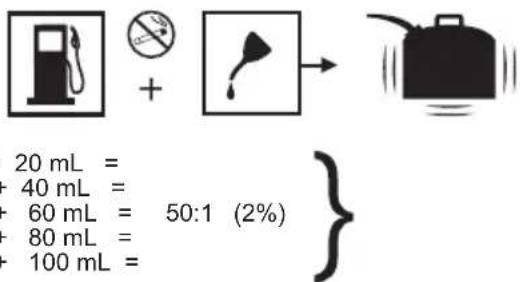
1 L + 20 mL =
2 L + 40 mL =
3 L + 60 mL = 50:1 (2%)
4 L + 80 mL =
5 L + 100 mL =

REMLISSAGE DU RÉSERVOIR
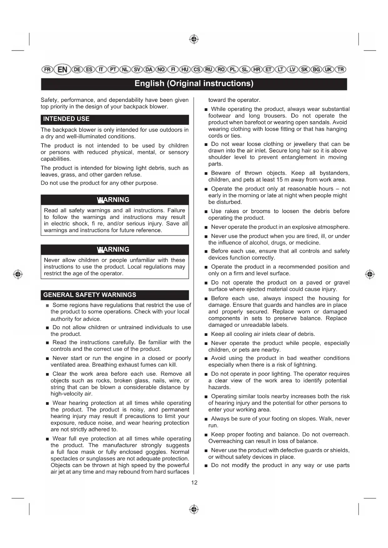
English (Original instructions)
Safety, performance, and dependability have been given top priority in the design of your backpack blower.
INTENDED USE
The backpack blower is only intended for use outdoors in a dry and well-illuminated conditions.
The product is not intended to be used by children or persons with reduced physical, mental, or sensory capabilities.
The product is intended for blowing light debris, such as leaves, grass, and other garden refuse.
Do not use the product for any other purpose.
WARNING
Read all safety warnings and all instructions. Failure to follow the warnings and instructions may result in electric shock, fire, and/or serious injury. Save all warnings and instructions for future reference.
WARNING
Never allow children or people unfamiliar with these instructions to use the product. Local regulations may restrict the age of the operator.
GENERAL SAFETY WARNINGS
■ Some regions have regulations that restrict the use of the product to some operations. Check with your local authority for advice.
■ Do not allow children or untrained individuals to use the product.
- Read the instructions carefully. Be familiar with the controls and the correct use of the product.
■ Never start or run the engine in a closed or poorly ventilated area. Breathing exhaust fumes can kill.
- Clear the work area before each use. Remove all objects such as rocks, broken glass, nails, wire, or string that can be blown a considerable distance by high-velocity air.
■ Wear hearing protection at all times while operating the product. The product is noisy, and permanent hearing injury may result if precautions to limit your exposure, reduce noise, and wear hearing protection are not strictly adhered to.
■ Wear full eye protection at all times while operating the product. The manufacturer strongly suggests a full face mask or fully enclosed goggles. Normal spectacles or sunglasses are not adequate protection. Objects can be thrown at high speed by the powerful air jet at any time and may rebound from hard surfaces
toward the operator.
■ While operating the product, always wear substantial footwear and long trousers. Do not operate the product when barefoot or wearing open sandals. Avoid wearing clothing with loose fitting or that has hanging cords or ties.
■ Do not wear loose clothing or jewellery that can be drawn into the air inlet. Secure long hair so it is above shoulder level to prevent entanglement in moving parts.
■ Beware of thrown objects. Keep all bystanders, children, and pets at least 15 m away from work area.
■ Operate the product only at reasonable hours – not early in the morning or late at night when people might be disturbed.
■ Use rakes or brooms to loosen the debris before operating the product.
■ Never operate the product in an explosive atmosphere.
■ Never use the product when you are tired, ill, or under the influence of alcohol, drugs, or medicine.
■ Before each use, ensure that all controls and safety devices function correctly.
■ Operate the product in a recommended position and only on a firm and level surface.
■ Do not operate the product on a paved or gravel surface where ejected material could cause injury.
■ Before each use, always inspect the housing for damage. Ensure that guards and handles are in place and properly secured. Replace worn or damaged components in sets to preserve balance. Replace damaged or unreadable labels.
- Keep all cooling air inlets clear of debris.
■ Never operate the product while people, especially children, or pets are nearby.
■ Avoid using the product in bad weather conditions especially when there is a risk of lightning.
■ Do not operate in poor lighting. The operator requires a clear view of the work area to identify potential hazards.
■ Operating similar tools nearby increases both the risk of hearing injury and the potential for other persons to enter your working area.
■ Always be sure of your footing on slopes. Walk, never run.
- Keep proper footing and balance. Do not overreach. Overreaching can result in loss of balance.
■ Never use the product with defective guards or shields, or without safety devices in place.
■ Do not modify the product in any way or use parts
English (Original instructions)
and accessories that are not recommended by the manufacturer.
WARNING
If the product is dropped, suffers heavy impact, or begins to vibrate abnormally, immediately stop the engine and inspect for damage or identify the cause of the vibration. Any damage should be properly repaired or replaced by an authorised service centre.
■ Do not touch the area around the silencer or engine of the product. These parts get hot during operation.
■ Stop the engine and allow the product to cool down before refuelling.
■ For refuelling and fuel mixing, chose an area that is well-ventilated, and is away from ignition sources, such as sparks or flames, and flammable materials.
■ Do not smoke when mixing fuel or filling the fuel tank.
■ Mix and store fuel in a container approved for fuel.
- Keep an appropriate type of fire extinguisher nearby for dealing with fuel fires.
■ Remember to securely refit the fuel tank cap before starting the engine. Check for fuel leaks.
■ Wipe up any fuel spillage. Move 9 m away from the refuelling site before starting the engine.
■ To reduce the risk of injury associated with contacting rotating parts, always stop the engine and disconnect the spark plug boot. Make sure all moving parts have come to a complete stop before:
• leaving the product unattended
- clearing blockages
- checking, cleaning, or working on the product
• inspecting the product after striking a foreign object
■ Immediately stop the engine in an event of accident or breakdown. Do not operate the product again until it has been fully checked by an authorised service centre.
WARNING
Your blower is fitted with a shoulder harness. Carefully adjust the harness to comfortably help to support the weight of the product and hang at your back with the bower tube at your right-hand side.
WARNING
Identify the quick release mechanism and practice using it before you start using the product. Its correct use may prevent serious injury in the case of an emergency. Never wear additional clothing over the harness or otherwise restrict access to the quick release mechanism.
BLOWER SAFETY WARNINGS
■ Wear a face filter mask in dusty conditions to reduce the risk of injury associated with the inhalation of dust.
■ Slightly dampen surfaces in dusty conditions.
■ Do not use the product near open windows.
■ Use the full blower nozzle extension so that the air stream can work close to the ground and perform effectively.
■ Do not point the blower nozzle in the direction of people or pets.
■ Never place objects inside the blower tubes.
■ Do not place the product on top of or near loose debris. Debris can be sucked into the intake vent, resulting in possible damage to the product.
RESIDUAL RISKS
Even when the product is used as prescribed, it is still impossible to completely eliminate certain residual risk factors. The following hazards may arise in use and the operator should pay special attention to avoid the following:
■ Injury caused by vibration
- Always use the right tool for the job. Use designated handles and restrict working time and exposure.
■ Hearing damage caused by exposure to noise – Wear ear protection and limit exposure.
- Injury from flying objects from the blower tube airflow.
- Wear eye protection at all times.
RISK REDUCTION
It has been reported that vibrations from handheld tools may contribute to a condition called Raynaud's Syndrome in certain individuals. Symptoms may include tingling, numbness, and blanching of the fingers, usually apparent upon exposure to cold. Hereditary factors, exposure to cold and dampness, diet, smoking, and work practices are all thought to contribute to the development of these symptoms. There are measures that can be taken by the operator to possibly reduce the effects of vibration:
- Keep your body warm in cold weather. When operating the product wear gloves to keep the hands and wrists
FR EN DE ES IT PT NL SV DA NO FI HU CS RU RO PL SL HR ET LT LV SK BG UK TR
English (Original instructions)
warm. It is reported that cold weather is a major factor contributing to Raynaud's Syndrome.
■ After each period of operation, exercise to increase blood circulation.
■ Take frequent work breaks. Limit the amount of exposure per day.
If you experience any of the symptoms of this condition, immediately discontinue use and see your physician.
WARNING
Injuries may be caused, or aggravated, by prolonged use of a tool. When using any tool for prolonged periods, ensure you take regular breaks.
MAINTENANCE
WARNING
Use only original manufacturer's replacement parts, accessories, and attachments. Failure to do so can cause possible injury and poor performance, and may void your warranty.
WARNING
Servicing requires extreme care and knowledge and should be performed only by a qualified service technician. For service, bring the product to an authorised service centre. When servicing, use only original replacement parts.
- Stop the engine, allow the product to cool down, and make sure all moving parts have come to a complete stop. Disconnect the spark plug boot before conducting any maintenance or cleaning work.
■ You may make adjustments and repairs described in this manual. For other repairs, contact an authorised service centre.
■ After each use, clean the product with a soft, dry cloth. - Check all nuts, bolts, and screws at frequent intervals for proper tightness to ensure that the product is in safe working condition. Any part that is damaged should be properly repaired or replaced by an authorised service centre.
■ Bring the product to an authorised service centre to replace damaged or unreadable labels.
CLEARING A BLOCKAGE
■ To reduce the risk of injury associated with contacting rotating parts, always stop the engine, and make sure
all moving parts have come to a complete stop.
■ Remove the blower tubes to inspect for blockage. Clear the tubes if required.
■ Reinstall the blower tubes before starting the product.
CLEANING THE AIR FILTER
See Fig. 6.
A wet or dirty air filter causes starting difficulty, loss of performance, and shorten the life span of the engine. The air filter should be checked and cleaned after 5 hours of operation. Inspect and clean more frequently if used in dusty dirty conditions.
For best performance, the air filter should be replaced yearly.
To clean the air filter:
- Press the air filter cover tab to open the air filter cover.
- Remove the cover.
- Lift the edge of the air filter carefully and peel it out.
- Wash the air filter with warm, soapy water.
- Rinse and squeeze to dry.
- To reinstall the air filter cover, insert the tabs into the notches and lock into place.
NOTE: Make sure the filter is seated properly inside the cover. Installing the filter incorrectly will allow dirt to enter the engine, causing rapid engine wear.
CLEANING THE EXHAUST PORT, MUFFLER, AND SPARK ARRESTOR
NOTE: Depending on the type of fuel used, the type and amount of lubricant used, and/or your operating conditions, the exhaust port, muffler, and/or spark arrestor screen may become blocked with carbon deposits. If you notice a power loss with your petrol-powered product, you may need to remove these deposits to restore performance. We highly recommend that only qualified service technicians perform this service.
The spark arrestor must be cleaned or replaced every 50 hours or yearly to ensure proper performance of your product. Spark arrestors may be in different locations depending on the model purchased. Please contact your nearest service dealer for the location of the spark arrestor for your model.
WARNING
To avoid a fire hazard, never run the blower without the spark arrestor in place.
English (Original instructions)
FUEL CAP
WARNING
A leaking fuel cap is a fire hazard and must be replaced immediately.
The fuel cap contains a sealing gasket and a check valve to allow air in. A clogged check valve will cause poor engine performance. If performance improves when the fuel cap is loosened, the check valve may be faulty. Replace fuel cap if required.
When refi tting the fuel cap ensure it is not cross-threaded, otherwise it will leak.
FUEL FILTER
The fuel supplied to the engine is passed through a filter to remove any contaminants from entering the engine. Contaminants in the fuel can cause poor performance and damage to the engine.
The fuel fi Iter is a non-serviceable item and, if needed, should be replaced by an authorised service centre.
SPARK PLUG REPLACEMENT
See Fig. 7.
The product's engine uses a Champion RCJ4 spark plug. Use an exact replacement.
-
Remove the spark plug boot.
-
Loosen the spark plug by turning it counter-clockwise with a socket.
-
Remove the spark plug.
-
Inspect the new spark plug. The spark plug must be properly gapped and free of deposits in order to ensure proper engine operation. The correct gap is 0.63 mm. To widen gap, if necessary, carefully bend the ground (top) electrode. To lessen gap, gently tap ground electrode on a hard surface.
-
Hand thread the new spark plug into the cylinder, turning it clockwise.
■ Tighten with a socket. Torque to 24,40 Nm (216 lb.in.) minimum, 29,82 Nm (264 lb.in.) maximum. Do not over-tighten.
WARNING
Be careful not to cross-thread the spark plug. Cross-threading will seriously damage the product.
TRANSPORTATION AND STORAGE
■ Stop the engine and allow it to cool down before storing or transporting.
■ Clean all foreign materials from the product.
- Drain all fuel from the tank into a container approved for petrol. Remember to properly replace and tighten the fuel cap.
■ Run the engine until it stops. This will remove all fuel that could become stale and leave varnish and gum in the fuel system.
■ If applicable, drain all lubricant from the engine into a container approved for lubricant. Remember to properly replace the lubricant cap.
■ Store the product in a cool, dry, and well-ventilated place that is inaccessible to children and well away from sources of ignition.
- Keep away from corrosive agents such as garden chemicals and de-icing salts.
■ Do not store outdoors.
■ When transporting the product in a vehicle, secure it against movement or falling to prevent injury to persons or damage to the product.
■ Never carry or transport the product while the engine is running.
■ Abide all government and local regulations for the safety storage and handling of petrol.
Short term storage (less than 1 month)
■ Stop the engine and allow the product to cool down before storing or transporting.
■ Clean all foreign materials from the product.
■ Store the product in a cool, dry, and well-ventilated place that is inaccessible to children and well away from sources of ignition.
- Keep away from corrosive agents such as garden chemicals and de-icing salts.
■ Do not store outdoors.
SYMBOLS
Some of the following symbols may be used on this tool. Please study them and learn their meaning. Proper interpretation of these symbols will allow you to operate the tool better and safer.


Precautions that involve your safety.
To reduce the risk of injury, you must read and understand the operator's manual before using the product.
Wear eye protection at all times when operating the product.
English (Original instructions)


Wear hearing protection at all times when operating the product.
Risk of long hair being drawn into air intake.
Do not operate the product without the blower tubes in place.
Risk of loose clothing being drawn into the air intake.
Do not run product while the air intake door is unsecured.
Beware of thrown or flying objects. Keep all bystanders at least 15 m away.
Rotating fans. Keep hands and feet out of openings while the product is running.
Use unleaded petrol intended for motor vehicle with an octane rating of 91([r+m]/2) or higher.
Use 2-stroke oil for air-cooled engines.
Mix the fuel mixture thoroughly and also each time before refuelling.
To reduce the risk of injury or damage, avoid contact with any hot surface.
Set the ignition switch to the "O" (off) position.
Unlock the cruise control lever.
Set the choke lever to "A" position.
Set the choke lever to "B" position.
Pull the starter grip until the engine attempts to start.
Press the primer bulb 10 times.
Run the product.
Allow the engine to run for 10 seconds before using the product.
Pull: Quick release tab

Choke position A Choke position B

Starting a cold engine

Starting a warm engine

Conforms to all regulatory standards in the country in the EU where the product is purchased.

EurAsian Conformity Mark

Ukrainian mark of conformity

The guaranteed sound power level is 110 db.

Do not smoke when mixing fuel or filling fuel tank.
The following signal words and meanings are intended to explain the levels of risk associated with the product.
DANGER
Indicates an imminently hazardous situation, which, if not avoided, will result in death or serious injury.
WARNING
Indicates a potentially hazardous situation, which, if not avoided, could result in death or serious injury.
CAUTION
Indicates a potentially hazardous situation, which, if not avoided, may result in minor or moderate injury.
CAUTION
Without safety alert symbol
Indicates a situation that may result in property damage.
KNOW YOUR PRODUCT
See figure 1.
- Upper tube
- Throttle trigger
- Cruise control
- Ignition switch
- Adjustable harness and waist straps
NOTE: the straps are "quick release" type. - Choke lever
- Lower tube
English (Original instructions)
- Bellows tube
- Nozzle
- Primer bulb
ASSEMBLY
UNPACKING
The product requires assembly.
■ Carefully remove the product and any accessories from the box. Make sure that all items listed on the packing list are included.
WARNING
Do not use the product if any parts on the packing list are already assembled when you fi rst open the box. The parts on the packing list are not assembled by the manufacturer and require customer installation. Use of a product that may have been improperly assembled could result in serious personal injury.
■ Carefully inspect the product to make sure no breakage or damage occurred during shipping.
■ Do not discard the packing material until you have carefully inspected and satisfactorily operated the product.
■ If any parts are damaged or missing, please call your Ryobi service centre for assistance.
PACKING LIST
■ Backpack blower
■ Upper tube
■ Bellows tube
■ Lower tube
Nozzle
■ Locking clamps
■ Adjustable harness and waist straps
■ Bottle of 2-cycle engine lubricant
■ Operator's manual
Figure sheet
NOTE: Read and remove all hang tags and store with your operator's manual.
WARNING
If any parts are damaged or missing, do not operate the product until the parts are replaced. Use of the product with damaged or missing parts could result in serious personal injury.
WARNING
Do not attempt to modify the product or create accessories not recommended for use with the product. Any such alteration or modification is misuse and could result in a hazardous condition leading to possible serious personal injury.
WARNING
To prevent accidental starting that could cause serious personal injury, always disconnect the engine spark plug wire from the spark plug when assembling parts.
ASSEMBLING AND DISASSEMBLING THE UPPER TUBE AND BELLOWS TUBE
See Fig. 2.
- Attach the bellows tube to the main housing outlet and secure with a locking clamp.
- Attach the upper tube to the bellows tube. Secure the upper tube in place using the locker clamp.
- To disassemble, loosen the locking clamps using a hex wrench. Pull the upper tube and bellows tube from the main housing.
ASSEMBLING AND DISASSEMBLING THE LOWER TUBES AND NOZZLE
See Fig. 2.
- Align the raised locking tabs on the lower tube to the slots on the upper tube. Slide together and tighten securely by twisting.
- Secure the nozzle and lower tube together by aligning the raised locking tab on the lower tube with the raised slot on the nozzle.
- To disassemble, raise the locking tab with a fl at head screwdriver, rotate the tube and nozzle to unlock and remove from the main housing outlet.
ADJUSTING THE HARNESS AND WAIST STRAPS
CAUTION
Make all adjustments to the harness straps before starting the blower to avoid the possibility of injury.
To adjust harness strap assembly:
■ The blower should be in operating position before adjusting the harness straps. Slip your arm through the harness strap and onto your shoulder, then repeat for the other shoulder.
■ There are two possible height adjustment positions that can be used to easily adjust the harness.
FR EN DE ES IT PT NL SV DA NO FI HU CS RU RO PL SL HR ET LT LV SK BG UK TR
English (Original instructions)
■ Slip top buckle of the harness from adjustment slot and position to your desired height location.
■ Tighten (pull down on strap) or loosen (lift up the tab of the strap buckle) each harness strap as needed, until each is adjusted to a comfortable operating position.
■ The chest strap should be tightened or loosened until adjusted to a comfortable operating position.
To adjust waist strap assembly:
■ The waist strap should be tightened or loosened until adjusted to a comfortable operating position.
OPERATION
WARNING
Petrol is extremely flammable and explosive. A fire or explosion from petrol will burn you and others.
MIXING THE FUEL
See Fig. 3.
■ The product is powered by a 2-stroke engine and requires pre-mixing petrol and 2-stroke oil. Pre-mix unleaded petrol and 2-stroke engine oil in a clean container approved for petrol.
■ The engine is certified to operate on unleaded petrol intended for automotive use with an octane rating of 91 ([R + M] / 2) or higher.
■ Do not use any type of pre-mixed petrol/oil from fuel service stations, this includes the pre-mixed petrol/oil intended for use in mopeds, motorcycles, etc.
■ Use synthetic 2-stroke oil only. Do not use automotive oil or 2-stroke outboard oil.
■ Mix 2% synthetic 2-stroke into the petrol. This is a 50:1 ratio.
■ Mix the fuel thoroughly and also each time before refuelling.
■ Mix in small quantities. Do not mix quantities larger than usable in a 30-day period. Synthetic 2-stroke oil containing a fuel stabilizer is recommended.
FILLING THE TANK
■ Clean surface around fuel cap to prevent contamination.
■ Loosen the fuel cap slowly to release pressure and to keep the fuel from escaping around the cap.
- Carefully pour the fuel mixture into the tank. Avoid spillage. Prior to replacing the fuel cap, clean and inspect the gasket.
■ Immediately replace the fuel cap and hand tighten. Wipe away any fuel spillage. Move 9m away from refuelling site before starting engine.
NOTE: It is normal for smoke to be emitted from a new engine during and after first use.
WARNING
Always shut off engine before refuelling. Never add fuel to a machine with a running or hot engine. Move at least 9 m from refuelling site before starting engine. Do not smoke.
STARTING AND STOPPING THE ENGINE
See Fig. 4.
WARNING
Never start or run the engine inside a closed or poorly ventilated area. Breathing exhaust fumes can kill.

English (Original instructions)
To start a cold engine:
- Press the primer bulb for 10 times.
NOTE: After the 10^th press, the fuel should be visible in the primer bulb. If not, continue pressing until the fuel is visible.
-
Unlock the cruise control.
-
Set the choke lever to "A" position.
-
Pull the starter grip until the engine attempts to start. Do not pull the starter grip for more than 5 times.
-
Set the choke lever to "B" position.
-
Pull the starter handle until the engine starts. Do not pull the starter grip for more than 6 times.
NOTE: If the engine does not start, return to "A" choke position and repeat the process beginning at step 3.
- Allow the engine to run for 10 seconds, before using the product.
To start a warm engine
-
Lock the cruise control.
-
Set the choke lever to "B" position.
-
Pull the starter handle until the engine starts. Do not pull the starter grip for more than 6 times.
-
Allow the engine to run for 10 seconds, before using the product.
To stop the engine
Press the on/off switch to off position (O).
HOT RESTART OF THE ENGINE
When operating in warmer ambient temperatures, additional cool-down time may be required to restart the engine. When refuelling, always allow the engine to cool for at least five minutes before adding fuel to the tank.
To restart the engine:
■ Set the choke lever to the "A" position until it clicks.
■ Return the choke lever to the "B" position.
NOTE: Do not depress the throttle trigger before pulling the starter grip, or you must repeat the first two steps.
■ Pull the starter grip and rope until the engine runs.
■ Slip your arm through harness strap and onto your shoulder, then repeat for the other shoulder. Adjust the straps to a comfortable position. Refer to Adjusting the Harness and Waist Straps section earlier in this manual.
■ Remove the product from your back for starting. To start the blower, refer to Starting and Stopping section earlier in this manual.
- Put on the blower again. The product should be operated on the operator's right side.
■ To keep from scattering debris, blow around the outer edges of a debris pile. Never blow directly into the centre of a pile.
■ Operate power equipment at reasonable hours only — not early in the morning or late at night when people might be disturbed. Comply with the times listed in local ordinances.
■ To reduce sound levels, limit the number of pieces of equipment used at any time.
■ Operate the blower at the lowest possible throttle speed to do the job.
■ Check your equipment before operation, especially the muffler, air intakes, and air filters.
■ Use rakes or brooms to loosen the debris before operating the product. Slightly dampen surfaces in dusty conditions.
■ Conserve water by using power blowers instead of hoses for many lawn and garden applications, including areas such as gutters, screens, patios, grills, porches, and gardens.
■ Watch out for children, pets, open windows, or freshly washed cars, and blow debris safely away.
■ Use the blower nozzle extension, so the air stream can work close to the ground.
■ Clean up after using blowers or other equipment.
■ Dispose the debris properly.
CAUTION
Do not place blower on top of or near loose debris. Debris may be sucked into blower intake vent resulting in possible damage to the product.
English (Original instructions)
TROUBLESHOOTING
If these solutions do not solve the problem contact your authorised service dealer.
| PROBLEM POSSIBLE CAUSE SOLUTION | ||
| Engine will not start. | No spark | Check spark. Remove spark plug. Reattach the spark plug cap and lay spark plug on metal cylinder. Pull the starter rope and watch for spark at spark plug tip. If there is no spark, repeat test with a new spark plug. |
| No fuel | Push primer bulb until bulb is full of fuel. If bulb does not fi II, primary fuel delivery sys tem is blocked. Con tact a servicing dealer. If prim e bulb fills, engine may be flooded, proceed to next item. | |
| Engine is flooded. | 1. Remove spark plug, then turn the product so the spark plug hole is aimed at the ground.2. Set the choke lever to “B” position and pull starter cord 10-15 times. This will clear excessive fuel from the engine.3. Remove any fuel from the product.4. Clean and reinstall the spark plug.5. Clean up any spilled fuel and move at least 9 m away before restarting.6. Pull starter handle 3 times with the choke lever at “B” position.7. If the engine does not start, set the choke lever to “B” choke position and repeat the normal starting procedure.8. If the engine still fails to start, repeat the procedure using a new spark plug. | |
| Starter rope is hard to pull. Contact a servicing dealer. | ||
| Engine starts but will not ac cel er ate. | Engine requires approximately three minutes to warm up. | Allow engine to completely warm up. If engine does not accelerate after three minutes, contact a servicing dealer. |
| Engine starts but will only run at high speed at half choke. | Carburettor requires adjustment. | Contact a servicing dealer. |
| Engine does not reach full speed and emits excessive smoke. | Lubricant and fuel mixture is incorrect. | Use fresh fuel and the correct 2-stroke lubricant mix. |
| Air fi Iter is dirty. | Clean air fi Iter. Refer to Cleaning the Air Filter section earlier in this manual. | |
| Spark arrestor screen is dirty. | Contact a servicing dealer. | |
| Engine starts, runs, and accelerates but will not idle. | Idle speed screw on carburettor requires adjustment. | Contact a servicing dealer. |
English (Original instructions)
MAINTENANCE SCHEDULE
| Before each use | After first month or 20 hours of operation | Every 3 months or 50 hours of operation | Every 6 months or 100 hours of operation | Every year or after 300 hours or operation | |
| Check engine lubricant ■ | |||||
| Change engine lubricant ■ | ■ | ||||
| Check air fi iter ■ | |||||
| Clean air fi iter ■ | |||||
| Change air fi iter ■ | |||||
| Check or adjust spark plug ■ | |||||
| Replace spark plug ■ | |||||
| Check or adjust idle speed ■ | |||||
| Clean spark arrestor ^1 | ■ | ||||
| Replace spark arrestor ^1 | ■ | ||||
| Check or adjust valve clearance ^1 | ■ | ||||
| Clean fuel tank and filter ^1 | ■ | ||||
| Check fuel hose ■ | |||||
| Inspect fuel filter ■ | |||||
| Replace fuel filter ■ | |||||
| Check all hose connections ■ | |||||
| Inspect fuel tank vapour vent (if equipped) | ■ | ||||
| Inspect carbon canister (carburettor models only) | ■ |
- These items should only be carried out by an authorised service centre.
NOTES:
■ Maintenance should be performed more frequently when product is used in dusty area.
■ When product has exceeded the maximum figures specified in the table, maintenance should still be cycled according to the intervals of time or hours stated herein.
Choke Position A Choke Position B

EINEN KALTEN MOTOR ANLASSEN

EINEN WARMEN MOTOR ANLASSEN

MACHEN SIE SICH MIT IHREM PRODUKT VERTRAUT
Siehe Abbildung 1.
$$ \begin{array}{rl} & 1\mathrm{L} + 20\mathrm{mL} = \ & 2\mathrm{L} + 40\mathrm{mL} = \ & 3\mathrm{L} + 60\mathrm{mL} = \ & 4\mathrm{L} + 80\mathrm{mL} = \ & 5\mathrm{L} + 100\mathrm{mL} = \end{array} \tag{50:1} $$

AUFTANKEN
1 L + 20 mL =
2 L + 40 mL =
3 L + 60 mL =
4 L + 80 mL =
5 L + 100 mL =
50:1 (2%)

LLENADO DEL DEPÓSITO
1 L + 20 mL = 2 L + 40 mL = 3 L + 60 mL = 4 L + 80 mL = 5 L + 100 mL =
50:1 (2%)

RIEMPIMENTO DEL SERBATOIO
1 L + 20 mL =
2 L + 40 mL =
3 L + 60 mL = 50:1 (2%)
4 L + 80 mL =
5 L + 100 mL =

ALGEMENE VEILIGHEIDSWAARSCHUWINGEN
1 L + 20 mL =
2 L + 40 mL =
3 L + 60 mL =
4 L + 80 mL =
5 L + 100 mL =
50:1 (2%)

DE TANK VULLEN
TRANSPORT OCH FÖRVARING
KJENN PRODUKTET DITT
Se fig. 1.
- ∅vre rør
- Gasshendel
- Cruise control
- Startbryter
- Justerbar sele og hoftereimer
MERK: Reimene er av typen "hurtigfrakobling". - Chokehendel
- Nedre rør
- Belgrør
- Dyse
- Pumpeblåse
MONTERING
OPPAKKING
Dette produktet krever montering.
1 L + 20 mL =
2 L + 40 mL =
3 L + 60 mL =
4 L + 80 mL =
5 L + 100 mL =
TANKOWANIE
$$ \begin{array}{l} \begin{array}{l} 1 \mathrm{L} + 20 \mathrm{mL} = \ 2 \mathrm{L} + 40 \mathrm{mL} = \ 3 \mathrm{L} + 60 \mathrm{mL} = 50: 1 (2\%) \end{array} \ \begin{array}{l l l} 4 \mathrm{L} & + & 8 0 \mathrm{mL} = \ 5 \mathrm{L} & + & 1 0 0 \mathrm{mL} = \end{array} \ \end{array} $$

POLNJENJE POSODE ZA GORIVO
OBOZNÁMTE SA S VAŠÍM PRODUKTOM
$$ \begin{array}{l} 1 \mathrm{L} + 2 0 \mathrm{mL} = \ 2 \mathrm{L} + 4 0 \mathrm{mL} = \ 3 \mathrm{L} + 60 \mathrm{mL} = 50:1 (2 \%) \ 4 \mathrm{L} + 8 0 \mathrm{mL} = \ 5 \mathrm{L} + 1 0 0 \mathrm{mL} = \ \end{array} $$

PLNENIE PALIVOVEJ NÁDRŽE
In addition to any statutory rights resulting from the purchase, this product is covered by a guarantee as stated below.
-
The warranty period is 24 months for consumers and commences on the date when the product was purchased. This date has to be documented by an invoice or other proof of purchase. The product is designed and dedicated to consumer and private use only. So there is no warranty provided in case of professional or commercial use.
-
There is a possibility to extend for a part of the range of garden tools (AC/DC) the warranty period over the period described above using the registration on the www.ryobitools.eu website. The eligibility of the tools for extension of the warranty period is clearly displayed in stores and / or on packaging / and contained within the product documentation. The end user needs to register his/her newly-acquired tools online within 30 days from the date of purchase. The end user may register for the extended warranty in his country of residence if listed on the online registration form where this option is valid. Furthermore, end users must give their consent to the storage of the data that are required to be entered online, and they have to accept the terms and conditions. The registration confirmation receipt, which is sent out by e-mail, and the original invoice showing the date of purchase will serve as proof of the extended warranty.
-
The warranty covers all defects of the product during the warranty period due to defaults in workmanship or material at the purchase date. The warranty is limited to repair and/or replacement and does not include any other obligations including but not limited to incidental or consequential damages. The warranty is not valid if the product has been misused, used contrary to the instruction manual, or being incorrectly connected. This warranty does not apply to:
– any damage to the product that is the result of improper maintenance – any product that has been altered or modified
– any product where original identification (trade mark, serial number) markings have been defaced, altered or removed
– any damage caused by non-observance of the instruction manual – any non CE product
– any product that has been attempted to be repaired by a non-qualified professional or without prior authorization by Techtronic Industries
– any product connected to improper power supply (amps, voltage, frequency)
– any product used with inappropriate fuel mixture (fuel, oil, percentage of oil)
– any damage caused by external influences (chemical, physical, shocks) or foreign substances
– normal wear and tear spare parts
– inappropriate use, overloading of the tool
– use of non-approved accessories or parts
– Any periodic adjustments to or maintenance cleaning of carburetors
- Components (parts and accessories) subject to natural wear and tear including but not limited to bump knobs, drive belts, clutch, blades of hedge trimmers or lawn mowers, harness, cable throttle, carbon brushes, power cord, tines, felt washers, hitch pins, blower fans, blower and vacuum tubes, vacuum bag and straps, guide bars, saw chains, hoses, connector fittings, spray nozzles, wheels, spray wands, inner reels, outer spools, cutting lines, spark plugs, air filters, gas filters, mulching blades, etc.
-
For servicing, the product must be sent or presented to a RYOBI authorized service station listed for each country in the following list of service station addresses. In some countries your local RYOBI dealer undertakes to send the product to the RYOBI service organisation. When sending a product to a RYOBI service station, the product should be safely packed without any dangerous contents such as petrol, marked with sender's address and accompanied by a short description of the fault.
-
A repair / replacement under this warranty is free of charge. It does not constitute an extension or a new start of the warranty period. Exchanged parts or tools become our property. In some countries delivery charges or postage will have to be paid by the sender. Your statutory rights arising from the purchase of the tool remain unaffected
-
This warranty is valid in the European Community, Switzerland, Iceland, Norway, Liechtenstein, Turkey and Russia. Outside these areas, please contact your authorized RYOBI dealer to determine if another warranty applies.
AUTHORISED SERVICE CENTRE
To find an authorised service centre near you, visit http://uk.ryobitools.eu/header/service-and-support/service-agents.
FR RYOBI® CONDITIONS D'APPLICATION DE LA GARANTIE
EC DECLARATION OF CONFORMITY
Techtronic Industries GmbH
Max-Eyth-Straße 10, 71364 Winnenden, Germany
Herewith we declare that the product
Backpack Blower
Brand: Ryobi
Model number: RBL42BP
Serial number range: 46208301000001 - 46208301999999
is in conformity with the following European Directives
2006/42/EC, 2014/30/EU, 2000/14/EC, 2005/88/EC, 97/68/EC as last amended 2012/46/EU, EN 15503:2009+A2:2015, EN ISO 14982:2009, EN ISO 3744:2010
Measured sound power level: 108.4 dB(A)
Guaranteed sound power level: 110 dB(A)
Conformity assessment method to Annex V Directive 2000/14/EC amended by 2005/88/EC.

CE
Floyd Jeffrey Nesom (BSME)
Senior Director of Engineering
Winnenden, Dec. 29, 2016
Authorised to compile the technical file:
Alexander Krug, Managing Director
Techtronic Industries GmbH
Max-Eyth-Straße 10, 71364 Winnenden, Germany

DÉCLARATION DE CONFORMITÉ EC
Techtronic Industries GmbH
Max-Eyth-Straße 10, 71364 Winnenden, Germany
Winnenden, Dec. 29, 2016
Max-Eyth-Straße 10, 71364 Winnenden, Germany

Max-Eyth-Straße 10, 71364 Winnenden, Germany
Winnenden, Dec. 29, 2016
Max-Eyth-Straße 10, 71364 Winnenden, Germany

Max-Eyth-Straße 10, 71364 Winnenden, Germany
Winnenden, Dec. 29, 2016
Max-Eyth-Straße 10, 71364 Winnenden, Germany

Max-Eyth-Straße 10, 71364 Winnenden, Germany
Winnenden, Dec. 29, 2016
Max-Eyth-Straße 10, 71364 Winnenden, Germany
Max-Eyth-Straße 10, 71364 Winnenden, Germany
Director Sénior de Engenharia
Winnenden, Dec. 29, 2016
Max-Eyth-Straße 10, 71364 Winnenden, Germany
NL EC CONFORMITEITSVERKLARING
Techtronic Industries GmbH
Max-Eyth-Straße 10, 71364 Winnenden, Germany
Winnenden, Dec. 29, 2016
Max-Eyth-Straße 10, 71364 Winnenden, Germany
DA EC OVERENSSTEMMELSESERKLÆRING
Techtronic Industries GmbH
Max-Eyth-Straße 10, 71364 Winnenden, Germany
Vi erklærer hermed, at produktet
Rygsæksblæser
Brand: Ryobi
modelnummer: RBL42BP
Serienummeromrâ`de: 46208301000001 - 46208301999999
Winnenden, Dec. 29, 2016
Max-Eyth-Straße 10, 71364 Winnenden, Germany

SV EC-KONFORMITETSDEKLARATION
Techtronic Industries GmbH
Max-Eyth-Straße 10, 71364 Winnenden, Germany
Senior Director of Engineering
Winnenden, Dec. 29, 2016
Max-Eyth-Straße 10, 71364 Winnenden, Germany
NO EC-SAMSVARSERKLÆRING
Techtronic Industries GmbH
Max-Eyth-Straße 10, 71364 Winnenden, Germany
Winnenden, Dec. 29, 2016
Max-Eyth-Straße 10, 71364 Winnenden, Germany
FI EC-SÄÄNNÖSTEN NOUDATTAMINEN
Techtronic Industries GmbH
Max-Eyth-Straße 10, 71364 Winnenden, Germany
Winnenden, Dec. 29, 2016
Max-Eyth-Straße 10, 71364 Winnenden, Germany
Max-Eyth-Straße 10, 71364 Winnenden, Germany
Winnenden, Dec. 29, 2016
Max-Eyth-Straße 10, 71364 Winnenden, Germany

PL DEKLARACJA ZGODNOŚCI EC
Techtronic Industries GmbH
Max-Eyth-Straße 10, 71364 Winnenden, Germany
Winnenden, Dec. 29, 2016
Max-Eyth-Straße 10, 71364 Winnenden, Germany
HU EC MEGFELELŐSÉGI NYILATKOZAT
Techtronic Industries GmbH
Max-Eyth-Straße 10, 71364 Winnenden, Germany
Winnenden, Dec. 29, 2016
Max-Eyth-Straße 10, 71364 Winnenden, Germany
CS PROHLÁŠENÍ O SHODĚ EC
Techtronic Industries GmbH
Max-Eyth-Straße 10, 71364 Winnenden, Germany
Winnenden, Dec. 29, 2016
Max-Eyth-Straße 10, 71364 Winnenden, Germany
RO DECLARATIE DE CONFORMITATE EC
Techtronic Industries GmbH
Max-Eyth-Straße 10, 71364 Winnenden, Germany
Winnenden, Dec. 29, 2016
Alexander Krug, Director General
Techtronic Industries GmbH
Max-Eyth-Straße 10, 71364 Winnenden, Germany

LV EC ATBILSTĪBAS DEKLARĀCIJA
Techtronic Industries GmbH
Max-Eyth-Straße 10, 71364 Winnenden, Germany
Winnenden, Dec. 29, 2016
Max-Eyth-Straße 10, 71364 Winnenden, Germany
ET EC VASTAVUSDEKLARATSIOON
Techtronic Industries GmbH
Max-Eyth-Straße 10, 71364 Winnenden, Germany
Kinnitame, et see toode
Winnenden, Dec. 29, 2016
Max-Eyth-Straße 10, 71364 Winnenden, Germany
LT EC ATITIKTIES DEKLARACIJA
Techtronic Industries GmbH
Max-Eyth-Straße 10, 71364 Winnenden, Germany
Winnenden, Dec. 29, 2016
Max-Eyth-Straße 10, 71364 Winnenden, Germany
HR EC IZJAVA O USKLAĐENOSTI
Techtronic Industries GmbH
Max-Eyth-Straße 10, 71364 Winnenden, Germany
Winnenden, Dec. 29, 2016
Max-Eyth-Straße 10, 71364 Winnenden, Germany

SL IZJAVA EC O SKLADNOSTI
Techtronic Industries GmbH
Max-Eyth-Straße 10, 71364 Winnenden, Germany
Winnenden, Dec. 29, 2016
Max-Eyth-Straße 10, 71364 Winnenden, Germany
Max-Eyth-Straße 10, 71364 Winnenden, Germany
Winnenden, Dec. 29, 2016
Max-Eyth-Straße 10, 71364 Winnenden, Germany
SK PREHLÁSENIE O ZHODE EC
Techtronic Industries GmbH
Max-Eyth-Straße 10, 71364 Winnenden, Germany
Winnenden, Dec. 29, 2016
Max-Eyth-Straße 10, 71364 Winnenden, Germany
Max-Eyth-Straße 10, 71364 Winnenden, Germany
Winnenden, Dec. 29, 2016
Max-Eyth-Straße 10, 71364 Winnenden, Germany

TR EC UYGUNLUK BEYANI
Techtronic Industries GmbH
Max-Eyth-Straße 10, 71364 Winnenden, Germany
Winnenden, Dec. 29, 2016
Max-Eyth-Straße 10, 71364 Winnenden, Germany


Techtronic Industries GmbH
Max-Eyth-Straße 10,
71364 Winnenden, Germany
960478039-03