GSL 2 Professional - Laser level BOSCH - Free user manual and instructions
Find the device manual for free GSL 2 Professional BOSCH in PDF.
| Product Type | Floor Laser Level |
| Brand | Bosch |
| Model | GSL 2 Professional |
| Category | Laser Level |
| Dimensions (L x W x H) | 210 x 195 x 205 mm |
| Weight (according to EPTA 01:2014) | 1.4 kg |
| Power Supply | 4 alkaline batteries 1.5 V LR06 (AA) or 10.8 V Lithium-ion battery |
| Battery Life (alkaline) | 15 h |
| Battery Life (1.3 Ah battery) | 15 h |
| Battery Life (1.5 Ah battery) | 25 h |
| Laser Class | 3R (IEC 60825-1) |
| Laser Type | 630-670 nm, <5 mW |
| Range (without target) | 10 m |
| Range (with target) | 20 m |
| Leveling Accuracy | ±0.3 mm/m |
| Self-Leveling Range | ±4° |
| Typical Leveling Time | < 5 s |
| Operating Temperature | -10 °C to +50 °C |
| Storage Temperature | -20 °C to +70 °C |
| Protection Rating | IP 54 (dust and splash water protected) |
| Main Functions | Self-leveling, motorized rotation (via remote control), manual height adjustment, laser alignment |
| Included Accessories | Laser target plate, laser viewing glasses, transport case; RC 2 remote control (Set version) |
| Care and Cleaning | Clean with a soft, damp cloth; do not use detergents or solvents; store in the case |
| Safety | Class 3R laser – do not point the beam at eyes; remove batteries/battery pack before maintenance; use only original Bosch accessories |
| Spare Parts and Repairability | Repair only by an authorized Bosch after-sales service; 10-digit article number on the rating plate |
Frequently Asked Questions - GSL 2 Professional BOSCH
User questions about GSL 2 Professional BOSCH
0 question about this device. Answer the ones you know or ask your own.
Ask a new question about this device
Download the instructions for your Laser level in PDF format for free! Find your manual GSL 2 Professional - BOSCH and take your electronic device back in hand. On this page are published all the documents necessary for the use of your device. GSL 2 Professional by BOSCH.
USER MANUAL GSL 2 Professional BOSCH
ORI BRICEL-1545-007,bank Page 1 Tuesday, June 21, 2016 4:51 PM
Robert Bosch Power Tools GmbH
70538 Stuttgart
GERMONY
www.bosch-pt.com
160992A309[2014.07]1/209

160992A309
GSL Professional
2|2Set
RC 2 Professional

BOSCH
no Original drift systok
fi Alkuperaisjt object
elIoundruno aBpyv xprans
tr Original isocne Lalima
roInstruetioni originals
mkOpHnHaynrTa
bgOpHHHnHaHnCtysy
Originalnuputstvoarad
slzyimarnovdila
hr Originals upy
et Akumirane kasutusuhemr
All instructions must be read and observed in order to work safely with the measuring tool. Never make warning signs on the measuring tool unrecognisable. SAVE THESE INSTRUCTIONS FOR FUTURE REFERENCE AND INCLUDE THEM WITH THE MEASURING TOOL WHEN GIVING IT TO A THIRD PARTY.
- Caution - The use of other operating or adjusting equipment or the application of other processing methods than those mentioned here can lead to dangerous radiation exposure.
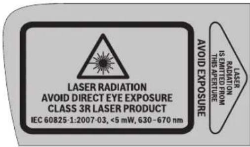
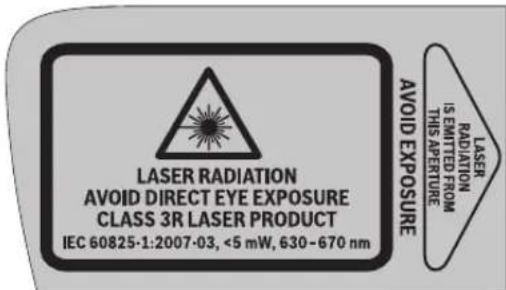
The measuring tool is provided with two warning labels (each marked with number 2 in the representation of the measuring tool on the graphics page).
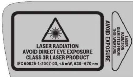
If the text of the warning labels is not in your national language, stick the provided warning labels in your national language over it before operating for the first time.
Do not direct the laser beam at persons or animals and do not look into the laser beam yourself. This measuring tool generates laser radiation from class 3R according to IEC 60825-1. Looking directly into the laser beam - even from a greater distance can cause damages to the eyes.


English|13
If laser radiation strikes your eye, you must deliberately close your eyes and immediately turn your head away from the beam.
Do not use the laser viewing glasses as safety goggles. The laser viewing glasses are used for improved visualisation of the laser beam, but they do not protect against laser radiation.
- Do not use the laser viewing glasses as sun glasses or in traffic. The laser viewing glasses do not afford complete UV protection and reduce colour perception.
Do not make any modifications to the laser equipment.
Have the measuring tool repaired only through qualified specialists using original spare parts. This ensures that the safety of the measuring tool is maintained.
- Avoid reflection of the laser beam on smooth surfaces such as windows or mirrors. A reflected laser beam can also cause damage to the eye.
The measuring tool should be operated only by persons that are familiar with the handling of laser devices. According to EN 60825-1, this includes, among other things, the knowledge about the biological effects of the laser to the eyes and the skin as well as the correct usage of laser protection devices in order to avoid dangers.
Do not operate the measuring tool in explosive environments, such as in the presence of flammable liquids, gases or dusts. Sparks can be created in the measuring tool which may ignite the dust or fumes.
Always set up the measuring tool in such a manner that the laser beams run far above or below eye level. This ensures that damage to the eyes will not occur.
Mark the area in which the measuring tool is being used with suitable laser warning labels. This prevents persons not involved from accessing the danger area.
Do not store the measuring tool at locations to which unauthorised persons have access. Persons not familiar with the operation of the measuring tool can cause harm to themselves and to others.
When using a class 3R measuring tool, observe possible national regulations. Non-observation of these regulations can lead to injury.
Make sure that the area of laser radiation is monitored or shielded. The limitation of laser radiation to controlled areas prevents eye damage to persons not involved.
Before any work on the measuring tool itself (e.g. assembling, maintenance, etc.) as well as when transporting and storing, remove the battery pack or the batteries from the measuring tool. Danger of injury when accidentally actuating the On/Off switch.
Do not open the battery pack. Danger of short-circuiting.

Protect the battery pack against heat, e.g., against continuous intense sunlight, fire, water, and moisture. Danger of explosion.
When battery pack is not in use, keep it away from other metal objects like paper clips, coins, keys, nails, screws, or other small metal objects that can make a connection from one terminal to another. Shorting the battery terminals together may cause burns or a fire.
Under abusive conditions, liquid may be ejected from the battery pack; avoid contact. If contact accidentally occurs, flush with water. If liquid contacts eyes, additionally seek medical help. Liquid ejected from the battery pack may cause irritations or burns.
In case of damage and improper use of the battery pack, vapours may be emitted. Provide for fresh air and seek medical help in case of complaints. The vapours can irritate the respiratory system.
Recharge only with the charger specified by the manufacturer. A charger that is suitable for one type of battery pack may create a risk of fire when used with another battery pack.
Use the battery pack only in conjunction with your Bosch measuring tool. This measure alone protects the battery pack against dangerous overload.
Use only original Bosch battery packs with the voltage listed on the nameplate of your measuring tool. When using other battery packs, e.g. imitations, reconditioned battery packs or other brands, there is danger of injury as well as property damage through exploding battery packs.

Keep the measuring tool and the laser target plate 10 away from cardiac pacemakers. The magnets of the measuring tool and laser target plate generate a field that can impair the function of cardiac pacemakers.
- Keep the measuring tool and the laser target plate 10 away from magnetic data medium and magnetically-sensitive equipment. The effect of the magnets of the measuring tool and laser target plate can lead to irreversible data loss.
Remote Control (GSL 2 Set)

Read and observe all instructions. SAVE THESE INSTRUCTIONS FOR FUTURE REFERENCE.
Have the remote control repaired only through a qualified repair person and only using identical replacement parts. This will ensure that the functionality of the remote control is maintained.
Do not operate the remote control in explosive atmospheres, such as in the presence of flammable liquids, gases or dusts. Sparks can be created in the remote control which may ignite the dust or fumes.
Product Description and Specifications
While reading the operating instructions, unfold the graphics page with the illustration of the surface laser and the remote control, and leave it open.
14|English
Intended Use
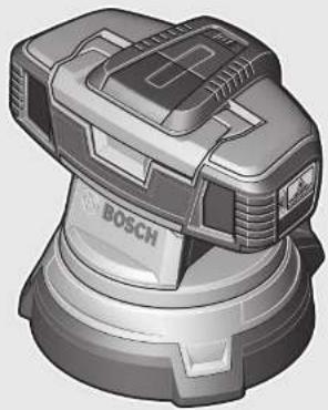
Surface laser
The measuring tool is intended for checking the flatness of floor surfaces.
The measuring tool is suitable for indoor use.
Remote Control (GSL 2 Set)
The remote control is intended for controlling surface lasers indoors.
Product Features
The numbering of the product features refers to the illustration of the surface laser and remote control on the graphics page.
Surface laser
1 Exit opening for laser beam
2 Laser warning label
3 Handle
4 Reception lens for remote control (GSL 2 Set)
5 Battery status indicator
6 Latch of battery lid
7 Battery lid
8 On/Off switch
9 Thumbwheel for height adjustment
10 Laser target plate
11 Measuring tip of the laser target plate
12 Serial number of the surface laser
23 Battery pack*
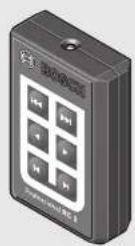
Remote Control
13 Outlet opening for infra-red beam
14 Button for fast rotation in anticlockwise direction
15 Button for slow rotation in anticlockwise direction
16 Button for step-by-step rotation in anticlockwise direction
17 Button for step-by-step rotation in clockwise direction
18 Button for slow rotation in clockwise direction
19 Button for fast rotation in clockwise direction
20 Battery lid of the remote control
21 Battery lid latch of the remote control
22 Serial number
Accessories/Spare parts
24 Laser viewing glasses
25 Case
The accessories illustrated or described are not included as standard delivery.
Technical Data
| Surface laser GSL 2 GSL 2 Set | ||
| Article number | 3601 K64 000 | 3601 K64 0013601 K64 0703601 K64 0R0 |
| Remote-controlled, motor-driven rotation base | -● | |
| Working range1) | ||
| - without laser target plate | 10 m | 10 m |
| - with laser target plate | 20 m | 20 m |
| Levelling Accuracy | ±0.3 mm/m ±0.3 mm/m | |
| Self-levelling range, typically | ±4° ±4° | |
| Levelling duration, typically | <5s <5s | |
| Operating temperature | -10°C...+50°C | -10°C...+50°C |
| Storage temperature | -20°C...+70°C | -20°C...+70°C |
| Relative air humidity, max. | 90% | 90% |
| Laser class | 3R | 3R |
| Laser type | 630-670 nm, <5 mW | 630-670 nm, <5 mW |
| C6 | 1 | 1 |
| Batteries (alkali-manganese) | 4x1.5VLR06(AA) | 4x1.5VLR06(AA) |
| Battery pack (lithium-ion) | 10.8V | 10.8V |
| Battery life | ||
| -Batteries (alkali-manganese) | 15 h | 15 h |
| -Battery pack (lithium-ion) (1,3 Ah) | 15 h | 15 h |
| -Battery pack (lithium-ion) (1,5 Ah) | 25 h | 25 h |
| Weight according to EPTA-Procedure 01:2014 | 1.4 kg | 1.4 kg |
| Dimensions (length x width x height) | 210 x 195 x 205 mm | 210 x 195 x 205 mm |
| Degree of protection | IP 54 (dust and splash water protected) | IP 54 (dust and splash water protected) |
| 1) The working range can be decreased by unfavourable environmental conditions (e.g. direct sun irradiation).For clear identification of your surface laser, see the serial number 12 on the type plate. | ||
160992A309|(21.6.16)
Bosch Power Tools

English | 15
Remote Control RC 2
| Article number | 3601 K69 C00 |
| Working range2) | 20 m |
| Operating temperature | -10 °C...+50 °C |
| Storage temperature | -20 °C...+70 °C |
| Batteries | 3 x 1.5 V LRO3 (AAA) |
| Weight according to EPTA-Procedure 01:2014 | 0.05 kg |
2) The working range can be decreased by unfavourable environmental conditions (e.g. direct sun irradiation).
For clear identification of your remote control, see the serial number 22 on the type plate.
Assembly
Power Supply of the Surface Laser
The measuring tool can either be operated with commercially available batteries or with a Bosch lithium ion battery pack.
Operation with Batteries (see figure B)
Alkali-manganese batteries are recommended for the measuring tool.
For installation and removal of the batteries, the measuring tool's height adjustment must be set to the lowest position. For this, turn the thumbwheel for height adjustment 9 in anticlockwise direction to the stop.
To open the battery lid 7, press on the latch 6 and fold the battery lid up. Insert the batteries. When inserting, pay attention to the correct polarity according to the representation on the inside of the battery lid.
Always replace all batteries at the same time. Only use batteries from one brand and with the identical capacity.
- Remove the batteries from the measuring tool when not using it for extended periods. When storing for extended periods, the batteries can corrode and self-discharge.
Operation with Battery Pack (see figure C)
Use only original Bosch lithium ion battery packs with the voltage listed on the nameplate of your measuring tool. Using other battery packs can lead to injuries and pose a fire hazard.
Note: Use of battery packs not suitable for the measuring tool can lead to malfunctions of or cause damage to the measuring tool.
Note: The battery pack is supplied partially charged. To ensure full capacity of the battery pack, completely charge the battery pack in the battery charger before using for the first time.
Use only the battery chargers listed on the accessories page. Only these battery chargers are matched to the lithium-ion battery pack that can be used in your measuring tool.
The Lithium-lon battery pack can be charged at any time without reducing its service life. Interrupting the charging procedure does not damage the battery pack.
The battery pack is equipped with a NTC temperature control which allows charging only within a temperature range of between 0^ and 45^ . A long battery pack service life is achieved in this manner.
For installation and removal of the battery pack 23, the measuring tool's height adjustment must be set to the lowest position. For this, turn the thumbwheel for height adjustment 9 in anticlockwise direction to the stop.
To insert the battery pack 23, press on the latch 6 and fold the battery lid 7 up. Slide the charged battery pack completely into the battery compartment and close the battery lid.
Operation with 1,5 Ah battery pack: In order to shut the battery lid 7, the foam damper on the inside of the battery lid must be removed.
To remove the battery pack 23, press on the latch 6 and fold the battery lid 7 up. Pull the battery pack out of the battery compartment.
Battery Status Indicator
The three green LEDs of battery status indicator 5 indicate the charge condition of the batteries or the battery pack 23.
LED Capacity
| Continuous lighting 3 x green | ≥2/3 |
| Continuous lighting 2 x green | ≥1/3 |
| Continuous lighting 1 x green <1/3 | |
| Flashing light 1 x green Reserve | |
Power Supply of the Remote Control (GSL 2 Set)
Using alkali-manganese batteries is recommended for operation of the remote control.
To open the battery lid 20, press on the latch 21 and remove the battery lid. Insert the batteries. When inserting, pay attention to the correct polarity according to the representation on the inside of the battery lid.
Always replace all batteries at the same time. Only use batteries from one brand and with the identical capacity.
- Remove the batteries from the remote control when not using it for longer periods. When storing for longer periods, the batteries can corrode and discharge themselves.
Operation
Starting Operation of the Surface Laser
Protect the measuring tool against moisture and direct sun light.
Do not subject the measuring tool to extreme temperatures or variations in temperature. As an example, do not leave it in vehicles for a long time. In case of large variations in temperature, allow the measuring tool to adjust to the ambient temperature before putting it into operation. In case of extreme temperatures or variations in temperature, the accuracy of the measuring tool can be impaired.
Avoid hard knocks to the measuring tool or dropping it. Damaging the measuring tool can cause accuracy to be
16 | English
compromised. Following a hard knock or fall, carry out a check by comparing the laser lines or plumb beams with a known horizontal or vertical reference line or verified perpendicular points.
- Switch the measuring tool off during transport. When switching off, the levelling unit, which can be damaged in case of intense movement, is locked.
Setting Up the Measuring Tool
Set up the measuring tool on the floor surface to be checked, ensuring that it is firmly positioned.
The levelling accuracy can be influenced through the ambient temperature. Especially temperature differences occurring from the ground upward can deflect the laser beam. As the thermal layering is greatest at ground level, the measuring tool should always be set up in the centre of the floor surface to be checked.
Switching On and Off
To switch on the measuring tool, slide the On/Off switch 8 to the "On" position. Immediately after switching on, the measuring tool sends laser beams out of the exit openings 1.
Do not direct the laser beam at persons or animals (especially not at their eye level), and do not stare into the laser beam yourself (not even from a distance).
To switch off the measuring tool, slide the On/Off switch 8 to the "Off" position. When switching off, the levelling unit is locked.
When the measuring tool is not moved or remote-controlled for approx. 30 minutes, it switches off automatically to save the batteries or the battery pack.
After switching off automatically, switch the measuring tool off via On/Off switch 8 and then on again, if required. GSL 2 Set: After switching off automatically, the measuring tool can be switched on again by pressing any button on the remote control.
Do not leave the switched-on measuring tool unattended and switch the measuring tool off after use. Other persons could be blinded by the laser beam.
When exceeding the maximum permitted operating temperature of 50^ , the measuring tool switches off to protect the laser diode. After cooling down, the measuring tool is ready for operation and can be switched on again.
Operation with battery pack: The "Electronic Cell Protection (ECP)" protects the lithium-ion battery pack against deep discharging. When the battery pack is discharged, the measuring tool is switched off by a protective circuit.
When the measuring tool switches off automatically due to a discharged battery pack, switch the measuring tool off with the On/Off switch 8. Charge the battery pack before switching the measuring tool on again. Otherwise, the battery pack could become damaged.
Allowing the Measuring Tool to Level In
After switching on, the levelling function automatically compensates irregularities within the self-levelling range of ± 4^ . The levelling is finished as soon as the laser beams do not move any more.
If the automatic levelling function is not possible, e.g. because the surface on which the measuring tool stands deviates by more than 4^ from the horizontal plane, the laser beams flash.
Set up the measuring tool in level position and wait for the self-levelling to take place. As soon as the measuring tool is within the self-levelling range of ± 4^ , the laser beams light up continuously.
In case of ground vibrations or position changes during operation, the measuring tool is automatically levelled in again, yet, possibly to a different height when larger position changes are the case. Upon re-levelling, check if the two laser beams are aligned at the reference point (see "Aligning the Height of the Measuring Tool", page 16) in order to avoid vertical errors.
Aligning the Height of the Measuring Tool
The measuring tool generates two laser beams that can be seen on the floor surface in front of the measuring tool for distances beyond 50~cm . The beams must be brought into alignment at this reference point, where they can initially be seen on the floor surface. For this, turn the thumbwheel for height adjustment 9 clockwise or anticlockwise, until both laser beams overlap at the reference point and only one beam can be seen.
When the two laser beams cannot be aligned by turning the thumbwheel, the position of the measuring tool is significantly above or below the floor surface. Position the measuring tool at a different location on the floor surface with less height deviation and align the laser beams there.
Starting Operation of the Remote Control (GSL 2 Set)
Protect the remote control against moisture and direct sunlight.
Do not subject the remote control to extreme temperatures or variations in temperature. As an example, do not leave it in vehicles for longer periods. In case of large variations in temperature, allow the remote control to adjust to the ambient temperature before putting it into operation.
The remote control remains ready for operation as long as a battery with sufficient voltage is inserted.
The signals of the remote control should reach the reception lens 4 directly from the front and inclined from above. When the remote control cannot be pointed directly against a reception lens, the working range is reduced. By reflecting the signal (e.g. against walls), the working range can be improved, even for indirect signals.
Switching the measuring tool on via the remote control after automatic shut-off of the measuring tool is only possible when the On/Off switch 8 is still in the "On" position. Switching the measuring tool off with the remote control is not possible.


Measuring Procedure
Manual Rotation (GSL 2)
Rotate the upper part of the measuring tool to the location that you want to check. After rotating, wait until the measuring tool has levelled in again and the laser beams no longer move. Then, check if the laser beams run opaque.
Automatic Rotation (GSL 2 Set)
To check the surface, rotate the upper part of the measuring tool with the remote control. Manual rotation is not possible.
The following rotation modes are available:

Press button 19 to start fast, continuous rotation in clockwise direction. Pressing button 19 again ends the rotation.

Press button 14 to start fast, continuous rotation in anticlockwise direction. Pressing button 14 again ends the rotation.

Press button 18 to start slow, continuous rotation in clockwise direction. Pressing button 18 again ends the rotation.

Press button 15 to start slow, continuous rotation in anticlockwise direction. Pressing button 15 again ends the rotation.

Press button 17 for a single, brief rotation step in clockwise direction. For each further individual movement, press button 17 again.

Press button 16 for a single, brief rotation step in anticlockwise direction. For each further individual movement, press button 16 again.
Evaluating Measuring Results (see figures D - G)
The two laser beams indicate, whether the surface is at the same height as the reference point (see "Aligning the Height of the Measuring Tool", page 16):
- All points, at which both laser beams coincide exactly above each other, are at the same height as the reference point.
- When two beams can be seen next to each other or when the laser beams are interrupted, the height of the floor surface deviates with respect to the reference point at this location.
To measure the deviation of the floor surface, position the laser target plate 10 at the location to be checked. Turn the laser target plate in such a manner that the lefthand laser beam coincides with the left reference line of the laser target plate. Slide the upper part of the laser target plate upward or downward, until the tip 11 of the laser target plate rests on the
location to be measured. The height deviation between the reference point and the measuring point can be read in mm via the position of the righthand laser beam on the laser target plate.
When both laser beams run apart at a constant angle on the floor surface, the floor surface is inclined.
Working Advice
Pay attention that the complete width of the laser beams coincide exactly over each other. The width of the laser beams changes with the distance.
Transporting the Measuring Tool
The handle 3 can be used for easier transport of the measuring tool. Fold the handle up as required.
Laser Viewing Glasses (Accessory)
The laser viewing glasses filter out the ambient light. This makes the red light of the laser appear brighter for the eyes.
Do not use the laser viewing glasses as safety goggles. The laser viewing glasses are used for improved visualisation of the laser beam, but they do not protect against laser radiation.
Do not use the laser viewing glasses as sun glasses or in traffic. The laser viewing glasses do not afford complete UV protection and reduce colour perception.
Recommendations for Optimal Handling of the Battery Pack
Protect the battery pack against moisture and water.
Store the battery pack only within a temperature range between 0^ and 50^ . As an example, do not leave the battery pack in the car in summer.
A significantly reduced working period after charging indicates that the battery pack is used and must be replaced.
Observe the notes for disposal.
Maintenance and Service
Maintenance and Cleaning
Before any work on the measuring tool itself (e.g. assembling, maintenance, etc.) as well as when transporting and storing, remove the battery pack or the batteries from the measuring tool. Danger of injury when accidentally actuating the On/Off switch.
Store and transport the surface laser only in the supplied case.
Keep the surface laser and remote control clean at all times. Do not immerse the surface laser and remote control into water or other fluids.
Wipe off debris using a moist and soft cloth. Do not use any cleaning agents or solvents.
Regularly clean the surfaces at the exit opening of the laser in particular, and pay attention to any fluff or fibres.
If the surface laser or remote control should fail despite the care taken in manufacture and testing, repair should be carried out by an authorised customer services agent for Bosch power tools. Do not open the surface laser and the remote control yourself.
In all correspondence and spare parts orders, please always include the 10-digit article number given on the type plate of the surface laser and remote control.
For repairs, only send in the surface laser in the case.
18 | English
After-sales Service and Application Service
Our after-sales service responds to your questions concerning maintenance and repair of your product as well as spare parts. Exploded views and information on spare parts can also be found under:
www.bosch-pt.com
Bosch's application service team will gladly answer questions concerning our products and their accessories.
Great Britain
Robert Bosch Ltd. (B.S.C.)
P.O.Box 98
Broadwater Park
North Orbital Road
Denham
Uxbridge
UB95HJ
At www.bosch-pt.co.uk you can order spare parts or arrange the collection of a product in need of servicing or repair.
Tel. Service: (0844) 7360109
E-Mail: boschservicecentre@bosch.com
Ireland
Origo Ltd.
Unit 23 Magna Drive
Magna Business Park
City West
Dublin 24
Tel. Service: (01) 4666700
Fax: (01) 4666888
Australia, New Zealand and Pacific Islands
Robert Bosch Australia Pty. Ltd.
Power Tools
Locked Bag 66
Clayton South VIC 3169
Customer Contact Center
Inside Australia:
Phone: (01300) 307044
Fax: (01300) 307045
Inside New Zealand:
Phone: (0800) 543353
Fax: (0800) 428570
Outside AU and NZ:
Phone: +61 3 95415555
www.bosch.com.au
Republic of South Africa
Customer service
Hotline: (011) 6519600
Gauteng - BSC Service Centre
35 Roper Street, New Centre
Johannesburg
Tel.: (011) 4939375
Fax: (011) 4930126
E-Mail: bsctools@icon.co.za
KZN - BSC Service Centre
Unit E, Almar Centre
143 Crompton Street
Pinetown
Tel.: (031) 7012120
Fax: (031) 7012446
E-Mail: bsc.dur@za.bosch.com
Western Cape - BSC Service Centre
Democracy Way, Prosperity Park
Milnerton
Tel.: (021) 5512577
Fax: (021) 5513223
E-Mail: bsc@zsd.co.za
Bosch Headquarters
Midrand, Gauteng
Tel.: (011) 6519600
Fax: (011) 6519880
E-Mail: rbsa-hq.pts@za.bosch.com
Transport
The usable lithium-ion battery packs are subject to the Dangerous Goods Legislation requirements. The user can transport the battery packs by road without further requirements. When being transported by third parties (e.g. via air transport or forwarding agency), special requirements on packaging and labelling must be observed. For preparation of the item being shipped, consulting an expert for hazardous material is required.
Dispatch battery packs only when the housing is undamaged. Tape or mask off open contacts and pack up the battery pack in such a manner that it cannot move around in the packaging. Please also observe possibly more detailed national regulations.
Disposal

The surface laser, remote control, batteries, accessories and packaging should be sorted for environmental-friendlyly recycling.
Do not dispose of the surface laser, remote control and batteries into household waste!
Only for EC countries:
According to the European Guideline 2012/19/EU, electrical devices/tools that are no longer usable, and according to the European Guideline 2006/66/EC, defective or used battery packs/batteries, must be collected separately and disposed of in an environmentally correct manner.

Français | 19
Batteries no longer suitable for use can be directly returned at:
Great Britain
Robert Bosch Ltd. (B.S.C.)
P.O.Box 98
Broadwater Park
North Orbital Road
Denham
Uxbridge
UB95HJ
At www.bosch-pt.co.uk you can order spare parts or arrange the collection of a product in need of servicing or repair.
Tel. Service: (0844) 7360109
E-Mail: boschservicecentre@bosch.com
Battery packs/batteries:
Li-ion:
Please observe the instructions in section "Transport", page 18.
Subject to change without notice.
Français
Rotation manuelle (GSL 2)
Robert Bosch (France) S.A.S.
Bosch Service Center
Telegrafvej 3
2750 Ballerup
Pá www.bosch-pt.dk kander online bestilles reservedele erer oprettes en reparations ordre.
TIf. Service Center: 44898855
Fax:44898755
E-Mail: vaerktoej@dk.bosch.com
Transport
Bosch Service Center
Telegrafvej 3
2750 Ballerup
Danmark
Tel.: (08) 7501820 (inom Sverige)
Fax: (011) 187691
Transport
Xpnoaepwva Tev npooipopo
Aeep empavewv
To epyaleio mepnnc npoopicetai yia tov eeyxo ncoaaoTn. ta6anoeiv.
Toepyaleio pTeponc eivai kataaan yia xpion oe cowtepi koucsxupouc.
Tnlexeiupooc (GSL 2 Set)
O nlexepiaoic npooipzetai yia tov eeyxo lezep enipaveiv oe eotepikouc xupouc.
Aneikoviömeva otoxieia
H anapiunonTov otoeiowou anekovictovat avapepetai OTnv anekovian Tou aeepenipaveiwv kau Tnlexipiaou OTn aeia pa ypapka.
Aieep emapveow
1EoocakivacLeceP
2Ipooeofooinrki mivaiklaaieep
3Aaβn
78 EAAynvka
4 DaKocAunnc yiaTnAeXeiapriotipio (GSL 2 Set)
5'EveEeK katataaocfopntan
6Aopaleo Tou kanakiou hknqmuatapia
7 Kanaki θηκις ματαρίας
8 Dαkɒmnc ON/OFF
9Iepioppeoepoevo koupi npcpuoiang uouous
10\Pivakac oToxueoan LcEep
11 Mutn metpnangtou nivaoka tOxueanLieZep
12 ApiooC oepoc Tou aeipoeiipavew
23 EnavaaopnOeV npataia
TnAeepiouoC
13 Avoiya eEodou yia unepuopn aktiva
14 PAnKtpo yia ynpyo npiaqa pe popa avtIeTn Tc wpo- loyiaik
15 PAnKtpo yia apyo yupioa me popa avtiEtn TnC wpoLoyI
16 PAnKtpo yia BnmuAtko yupioa pe popa avTtettn Tc wpo- loyaiak
17 PAnKtpo yia BnJatiko yupia ma e opoLoayakn foopa
18 PAnKtpo yia apyo yupiqa me wpoLoyaikiΦopa
19Piikpo yiphyopo yupiae wpoayiak npd
20 Kanaki Ohnnc matapiaac nayexipioou
21Aopaleia Tou kanakiou oKncmuatapiacn aeexipou
22 ApiOoC oepdC
EaprijmuA/AvtAAkTuKa
24 Fuaiia napatnpnojc leiCep
25 BaLiTa
Eapntmuataouaneikovizovta nepiypapovtai dev nepieoxvtal stnotavtpoekuaia.
Texvika xapaaktnpotiika
Euvtnpnon kal Service
Suvtnpnoan kalkaθapiaooc
Na apaieire mmuatapia n, avaloya, m enavaopopto meynmuatapia an to epyaleio metpnoanc npiv dieayete kanaia epyaia o' auto (n.x. epyaoies kaapouou, auvtionc knn.) kaoc kal npiv tn metaopaip nTv aothkeu on tou. 2e nepiwn gn aeIantou xeiipouou Tou biakomn ON/OFF dnioupeirai kivduvoctpauiouou.
Na ano9nkeeTe kai va metaapepeTe to epyaaleo metponc naVTOte mea atn baIrtz aou to ouvoeuei.
Na diatnpieTo lezep enipaveivw kai to xepiopnpo navtoe KaahpKaataaon.
Mny BuioeTe to leZep enipavewky kai To nAexeiopitnpio de vpo n aaa upa.
Kaaglcte tuxov pounoc kai pwueic eva uypo, naKvi. Mn xnpaonoiie te aea kaopaou n diautec.
Na kaapizete TAKIka idialtepa tic enipaveiec kovt aOny Ego do ntc aktivac lezep kalva npooexete va un dnmuouyouvtai xvoudia.
Avnap'0eicnneiueaevecpeooboukataaekuncklexyou To aleep emapaveivow n/kaTOnLexepiaptno talphaHooov ka note va aeitoupyov, toe eniokeun Tounc npenei avatege 0 eEv Eouoiodotmevo ouvpeyio ia naekptika epyaia tnc Bosch.Mnv avolEte o idoc/n iiaTo alecpemapveivow kai TnAeipiotpio.
'Otav zntate diaaaptnikc nnpoapopiec kaoockai otavnapayyelave avtalaknika npenei va avapepete onwo6hnoto 10pio apioeupetnou aoayappeta onnv mivakiada kataokeuaot tou lecepe enipaveiw h tou tnlexeiptpiou.
Na anooteAeTo AieCep emapaveW yia eiokeun poea otBaalirzaou to ouvobei.
Service kal npoxn ououawxphns
To Service anavrta otic epwthoeic oac oxyeku me tyn emokuekui kai tn ouvtponan tou npoiovoc acKaohc yia ta katalnaa avtalakikda:
www.bosch-pt.com
H ouda napoxc ouubouawv nC Bosch anavr euxapiotwC otic epwtnoeic oac oxetikä paT npoiovra ja kai ta avtalakKTiKa Touc.
EAAa6a
Robert Bosch A.E.
Epxia37
19400Kopwni-Athya
Tel.: 2105701270
Fax: 2105701283
www.bosch.com
www.bosch-pt.gr
ABZ Service A.E.
Tel.: 2105701380
Fax: 2105701607
Metaφορα
Opiexoeve enavaopoptoovee natapeicovw Athou 10keivta ot anaitrae ctwv enikivuvay aahov. O enava- opevec natapeic npopoovvaetaepoov anto xpn-otn obikw, xwplic alaooc opouc.
Otau, ooc, o enavaopptioevec matapie c aootellovta ano tpiouc (n.x. aeponopikoc n peetia petaopov) npene va Tnpovtai diapopec ibiatrepec anatnoec yia tn oukeuaa kai tn anuavon. E6w npenei, kata tv npoeoiuaia tou uno anootoan Teayiou, va 2ntnei onomega note kai n oumbouh evoc eikouyia enikivouva ayaa.
Na anotetaleTic enavaopoptoveecmuatapiec mvo otav to nepiBna eivai dKto. Na kAATE TIC yuvceneapc me kOaNTkTAivia kai va ouokeuaTe Tny enavaopptoevni unatapla kata tetoio Tpno, wote aut v ma KouviTaIe a Oa oon oukeuaia.
Iapakaoue va lauabave enlnc unoynackai tuxov nio auotmpec eovikc diataeic.
Anoupon

Ta dxpoeta leizep eniapaveiwotnlaexeiipntpio,oi enavaopopticoecekai nenavaopoptcpevecmuatapiekaowkai oiaouakeuaiepcenei va avakukawovtai pto piaiknpoc to npiaalov.
Mny pIeTeTo IeIepenpaveeiW, To nIeXeiipotnpoKaiTic ena-vaopoptooevec kai n enavaopptopevec unatapie. Ota anoppimuata tou oannou oac!
Movi yia xwpec tnc EE:
UuPwva e Tny KoivotnK Odyia 2012/19/EE oxetka e tic axonotec nAe Kptikce ouokuek caoak kai e Tny KoivotnO Odyia 2006/66/EK oxetka e tic yaaove c h avalouvec mntapie c ev elavn oev unoxpeewto npoiovta auta va auIeyovTAI Eexwiota yia va avakukawoov u pno foikko npoc to nepiabauov.
Mnatapiec/Enavapoprtojevecmuatapiec:
Li-Ion:
TapaKaIoue va doaote npoooxn otic unodeiEic oTo KepaAio AMetaopopa, 82.
Tnpoue to dikaiwa aalayw.

Türkçel 83
Türkce
Güvenlik Talimati
Lazerli yuzey distomatii

Bosch San. ve Tic. A.S.
Ahi Evran Cad. No:1 Kat:22
Polaris Plaza
80670 Maslak/Istanbul
Bosch Uzman Ekibi +90 (0212) 367 18 88
Isiklar LTD.STI
Kizilay Cad. No: 16/C Seyhan
Adana
Tel.: 0322 3599710
Tel.: 0322 3591379
Robert Bosch Sp. z o.o.
Bosch Service Center PT
K Vapence 1621/16
692 01 Mikulov
Na www.bosch-pt.cz si muzete objednat oprava Vaseho stroje online.
Tel.: 519305700
Fax: 519305705
E-Mail: servis.naradi@cz.bosch.com
www.bosch.cz
Preprava
He BckpbIbaiTe aKKyMyJrTOp.CuIeCTByeTOnaCHOctb KOPOTKOrO 3aMbIKAHRA.

3aunuanteakkymnyTopOTbblcOKHXtempeatyp,HnP.,OTINNTenbHorHarpeBaHHHaCONHue,ORHA,BOBI HBAH.CyueCTByeT onaCHOCTB B3pbIbA.
DePKHTe HEnCtONb3yeMbI aKKyMnTOp BdAnO t KaHcEJIaPcKnx CkpeNOK, MoHET, KIOUey, TBO3dei, BNHTOB NApYrHX MeJKNX MetaJIHueCKNX PpeDMetOB, KOtopBle MOrYT BbI3BaTb NepEMbIKAHHe KOHTAKTOB. KoTkoe 3ambKaHHe MExdy KOHTAKTamn aKKyMnTOpHO 6batae moKet npBODITb K OKoRAM ININ IOxapy.
Pn HnnpabnboHn 3KcnnyaTaunn MoKeT npOH3oHTN BbIeHHe nAkkymyTAOPHOJ KHKOCTH N3 AKKymyTAPOHa.36beraTe KOHTAKTCA c Hei. Pn CnyaHOM coPnKocOBeHHn pOmOte BOoM MeTO KOHTAKTApnNoaDHHn AkkymyTAOPHOJ KHKOCTH Brna3o 06paTHeB K BPVA 3a MeuHCHKOH NOMObU. BblNBuaCRn AkkymyTAOPHAR XHKOCTB cnoCo6Ha Bbi3BaTb KOKHbIe pa3dPaJaeHHn nn OKOrn.
PnIOBpeKdEHH HHe npabHbHom HcNoIb3ObaHH A KymyIaTpa MoYr BbIeNtcb NaIb.ObecneYe npToK CBexero BO3dyxa H6paTHecb K BPau PpHn HAnH nnXanob Ha coCToAHne 3doOpBB.BbIXaHne napOB MoKet pPiBcTeN K pa3dpaKeHIno DbIXaTeNbHix nyTeN.
3apKaTeakkMynTOpTobKcNOMOsbTO3apHbHXyCTPOBCTB,peKoMeHDoBAHHbIXH3rTOBHTeEM. 3apKaB3apHdHomycTPOCTBe,paccuTaHOMHa ONpeJeHHbBIDaKKMyIATOPOB,ApTyXaKKMyIATOPoB YpeBaTAOnaCHOCTbHO B3pBiBa.
HcnoIb3yIte aKKymyIaTOp TOnbKO B KOMnHaun C BaHm H3MePHTeNbHbIM HcTpyMeHToM Bosch. TOnbKO TaK BblcmOKeTe npedotBpaTb onachyio neperpy3ky aKKymyIaTopa.
HcnoB3yIe ToNbKO opHHnHaBHe aKKymnTOpB Bosch c HnpanpexHem, yka3aHHbIM Ha 3abOcKo Ta-6nnue KmepenbHoro HcTpyMeNTa. HcnoB30aB-Hne dpyrnx akyyMnyTOpHBx 6batape, Hapn, noDienok, BocTaHOBnEHbX akyyMnyTOpHBx 6batape HnAaKKymyTOpHBx 6batape npOn3BOJTeNe, UpeBaTo onaCHOCTbIO TpaBM MATEpHaBHO yUe6Ba B peYnbTaTe B3pbIBa.

HcTbHbBnAte H3MePHTeBbHbNHCtpy MeHb3nHyIO Mapky 10 B6bH3n KapnoCTMMyIaTOPOB.MaHNTbH3MePHTeBHO HcTpyMeHtA bH3npHOI MapKo3daOT MaHHTHOE NOE, KOTOpoe MOKeT Oka3bBaTb BnHnHe Ha pa6Oy KapNoCTMMyIaTOpa.
DepxHTe H3MePHTeBbHbIMHCtpyMeHTn Bn3nHyIO Mapky 10BdAnOT MaTHHBIXHOCTeNE DaHHbIX NpH6OpOB,yyBCTBHeTbHbIX K MaTHHOMY NOIIO.KeCTBHe MaHTHO H3MePHTeBbHO HOCTpyMeHTa N Bn3npHO MapKn MOxET PnBOITb K HeBOcNOHmO NoTepe DaHHbIX.
IynbTdNCTaHcHOnHOro ynpabHeHHa (GSL 2 Set)

Ipoounte H BbINONHnTe BCE yka3aHHCOXPAHHTE 3TN YKA3AHNIA.
Pemont BaWero NybTa HCTaHNOHOr OynpaBHeHn DOJKeH npOBoMDtCB TOnbKO KBaHnHnHPOBaHHbIMN CNEuHaHNTAMn HToBko CHCNoB3OBAHHeOpHnHaHBx 3anYacteT. ToBko TaK MoKHo rapaHTnpoBaTb COxpaHeHne FyHKUHOHaJIbHOcTH NylTa HCTaHIOHOHOr ynpaBHeHn.
He pa6oTaIe C npbTom HCTaHOnHo rO npabneHn BO B3pbIOONACHOcpe, NOBn3OCTN OTROPoHx XHKoTei,ra3OB Nblnn.Bn3MePHTeJIbHom HnCTpyMeHTe MOrY o6pa0BaTcR NCKpbl,OT KOTOpBX MOKETBOCIIaMeHHTBCa IIbII IN Napbl.
OnncanHe npoodykTa n ycnyr
IpoKaanyIcTa,OTKpOHTe packnAaHbIe CTpaHnCbI Cn3o6paKeHHem NOBepXHOCTHO Na3epa HnybTa ImCTaHNoHHOrO ynpabHeHn HocTabrIte 3TN CTpaHnCbI OTkpytBIMN, NOKa BbI h3yaeTe pykoBOdCTBO no kCnnNyatauH.
PpIMMeHHeHn No Ha3HaueHmO
TObepxHocThbI na3ep
M3MePHTeBbHINCTpyMeHT npedHa3HaueH nI npOBepKn POBHOCTN IOBepxHOCTn IOnla.
H3MePntBbHn HNCTpymEn PpeHa3HaueH nI HAONb30BaHH BHTPN NOMEeHn.
IyntdctaunhoHHo ynpabneHn (GSL 2 Set)
IynbTnCTaHcHNOHOr ynpabHeN npEHa3HaueH dna ynpabHeNIOBepxHOCTbIMNa3epaMn BHTPNOMeUeHN.

Bosch Power Tools
160992A309|(21.6.16)


118|Pysckn
H306paXeHHbIe coCTaBhIbe qactn
Hymepaun HA306paXeHHbIX KOMNOHEHTOB BbINONHeHa NPOcynkam Ha CTpaHnuaxC H306paXeHHem NOBepxHOCTHOIa3epa HnybTa IINCTaHUNOHHOY npabNEHNA.
PobepxHocThbI na3ep
1 OTrBepTne IINy BixOJa naepeHoro lyuA
2IpeynpeHntbHaTa6nkaNa3epHoroN3nyeHn
3PyKoRTKa
4PnHmHaHH3aDnIINCTAHIOHOrOynpaBHeHn (GSL2Set)
5 INHnKaTOp 3apJxKeHHocTH
6 Φικατορ κρβιχκ δαταρεύHOrO Οτεκα
7 Kpbliika 6batapeHoro OTecka
8BbiknouateNB
9 Nobopotha KONka InerpeylnpoBaHaNb BbICotb
0 Bn3npHa MapKa
11 N3MePHTeBbHn HakoHeuHK Bn3nPHoM MapKn
12 CepHHbH HOMeP IOBepXHOCTHOIa3epa
23 AkkymyTopHaa 6atapera
Pnblt dntaHnoHHoro ynpabneHH
13 OTBepCTHe BixOda INHpaKpaChoro Nyua
14 Khonka 6bictporo BpaueHnI npOTNb YacOBcTpeKN
15 Khonka MeIeHHoro BpaueHn npOTNB YacOBO CTpeKNI
16 Khonka noIarOBoro BpaueHn npOTNB YacOBoi CTpeKNI
17 Khonka noaroboro bpaenna no acoboi ctpenke
18 Khonka MedneHHoro BpaueHn no yacoboi ctpke
19 KhoIka 6bIcTporo BpaueHnno no yacobOc TpeKe
20Kpbiika6batapeHoroOTceKaIynbTaIhctaHIOHOYnpabneHHA
21 ΦнксаTop кршки батAPEн HorO отсекупьТа ДСТАнцИнHOrOу npaBneHnI
22 CepHnBHOmeP
PnHaIeXHoCTn/3aNactn
24 OuknДЯ pa60TbI c na3epHbIM INHCTpyMeHTOM*
25Футлар
H3o6paXeHHbIe Hnn OnncAHbIe npHaadJnxHoCTH He BxOaT B
CTaHapThbIM KOMnIeK TIOcTaBKn.
TexHHueckne daHhble
Pa60Ta c HcHCTpyMeHTOM
BbO B 3Kcnnyatauio nobepxhocthoro na3epa
3aunuHTe H3MePHTeIbHbI HnCTpyMeHrOT BnAHR npMbx CONHeUHbIXnyei.
He noDBepraTe H3MepeTebHbI HnCTpyMeT B03deCTBHO 3KCTpeMaJIbHbIX TempeaTp H TempeaTpHbIX nepenadoB. B aactHOCTm, He octabIe Iero Ha nHTeBHOte BpemBaMauHne. PnboBbIuX nepenadax TempeaTpyb CHaana DaIe H3MepeTebHOmy HnCTpyMeTcy CTa6HNHPOBaTB CBOIO TEMpeaTpPy, PpexJe cEm HAHHaTb paBOTaTB C Hm. 3KCTpeMaJIbHbIe TEMpeaTppyb H TempeaTpHyIe nepenadBi MOrTy OpiuaTeBHO BnIaTb Ha ToCHoCT H3MepeTebHOrO HnCTpyMeHTa.
H36eAte CNbHBix TOUKOB H naEHn H3MePHTenBHO HHCTpymTe. Nocne CNbHBx BHEWHX BO3deIcT-BH Heo6xoIMNO pOBepTb ToHOCt b HNBENHOBAHHN H3MePHTeBHO HOHCTpymTa B ABOTN3OBAHHO CEPBCHOH MaTePCKo Bosch.
Pn TpaHcnpOpNpOBKe BbIKNoaHTe H3MepeTEnbHbH NcTpymENT.Pn BbIKIOueHH6IOKnpyETc MaTHNKoBbMexAH3M,KOTOpBm Haue npEPEKIN DBHXEHnxMOXET 6bT NobpeXdH.
YctahOBka H3MePHTeNbHOro HnCTpyMeHa
YCTAHOBITHe N3MePHTeBbHINHCTpyMeHT Ha npOHOe OCHOBAHHe HA pOBepemOM yAcTke 3emn.
HaToHocb HnBEnIpOaHnMoKTe OKa3bIbTaB BnHnHHe Temepatypa Okpykaioe CpeDb.BoCobEHHoCTn TemepatHybIe nepenadbl, HmEOUme MeTO NO Mepe ydAeHEnOT noyBb, MOrT CTb PnHnHOt OKIOHeHn Na3epHOrO LyuA. NockOBky camble 6oJIbWe TEmnpatypbIe nepenadbl Ha6bIOAOTc B6N3n OT noYbI, N3MePntEBhN INCTpyMeHT Heo6xOIMO BcERda YcTAHabINBaTb NO cETHPy pOBepemOro yuaCTKa 3emnn
BklioueHne/BbIKIOUeHne
Yro6bI BKNIOUHTb H3MePHTeBbHbINHCTpyMeHT, NpeEbnHbTe BByKJIIOuATenb 8 B NOIOXeHHe «On». Cpa3y Nocne BKNIOUeHnH3MePHTeBbHb INHCTpyMeHTN3NyaaT na3epHbIe LyuHnO TBepCTn DnRA BbIXoDa Na3epHbIX Lyuei 1.
He HanpaBnIte Na3epHbI Nyu Ha IIOe H XKBOThbIX (Boc6eHHocTH Ha yPoBHrna) He CMOTpTe Ha na- 3epHbI Nyu (BkIOUaHc 60nbOro pacCToHHra.
IINBbIKIOueHnI3MePteIbHOI HCTpyMeHTa nepeBHNbTe BbIKIOUATEIb 8 B IIOJOxHeHNE «Off」.IpiBbIKIOueHHMaTHHKOBmMexAHN36NOKHyETc.
EcnHa npotraKeHH OK. 30MHN. BbHe 6yTepeMeaatb
H3MepHTeHbHn HnCTpymENTnH He 6yTe ynpabTb Hm C
nytbaDnCTaHnHOHOrO ynpaBNeHH, OH aBTOMaTHueCKn
OTKIOUaETc C ZelbIO EKOHOOMn 6atapeeknn AKKMyIANTOP-
HO6atapeH.
Iocne ABtOMaTHueCKOTo kKIOUeHn BbIKIOUHTe H3MePInTeBbHINHCTpMEnT C NOMOsbIO BbIKIOUaTeJI 8 n pN He0xOJIMOCTH CHOBA BKIOUHTeERO.
GSL 2 Set: Nocne abTOMaTHueCKORO OTKIIIOUeHHN3MepHTeIbHbI HnCTpyMeHT MOXHO BKNIOUHTb HaKaTHem IIO6oB KONKnHaIyIbTe DnCTaHcUNHOHOr ynpaBHeHH.
He octabnIte 6e3 npncMOTpa BKNIOUeHHbN K3MpHTeIbHbH NHCPTpymENT H bIKNOuAHTeero NOCE Nc-ONb3OBAHH. Ipyrne Iua MOrT 6bITb OcJIeINHebla3epHbIM nyoM.
Pn npBbIeHnn npEeBHo DOnyctHMo paOoeY tempeatpyb B 50°C npocxOoiT bblKIOueHn Ia3uNTbI na3epHorO dno. Pocne OXlaJckDHeN H3MePeHtBbHn HcTpyMEHT ONIbT roTOB K paOBe T moKet 6bITb ChOBa BKIOUeH.
3KcNpyataaOnoAkkymyIaTOPHO6bATepen: NITHeBOHnHaakymyIaTOPHa6bApTea3aunuHaOTrny60KoPa3pRAnCnCTeMoE«Electronic Cell Protection (ECP)」.PpnaP3pa3xJHHoAkkymyIaTOPHO6bATEeH3MePeTebHbInHCTpymENTBbIKIOUaTc8bnOaDapcxMe3aunbl.
EcnH3MepTeIbHbI HhCTpyMeHT ABTOMaTHueCKN OKKIOUHNcRn3-3pa3pKaeHHoCTn AKKMyIaTropHO BgATpei, BblKIOUHTe3MepTeIbHbIH NcTpyMeHT C NMOuBbO BkIIIOUaTeJI8. IpeXeJe cem ChOBa BKIOUaTB H3MepTeIbHbIH NcTpyMeHT, 3apJNTe AKKMyIaTropHyO bTaapeIO. HNahe Bo3MOxHO NOBpeKeHne AKKMyIaTropHO BgATpei.
ABTomatueckoe HHBenpoBaHne N3MepeHbHoro HHCTpymeHTA
Функua ABTomaueCKOrO HbENIpOBaHn BbipaBnBaET HePOBHOCTN Ba pAMKax dana3oHa aBTOMaTueeCKOrO HbENIpOBaHn B ±4°. HbENIpOBaHn 3aBepseHo, KaK TOnbKO na-3epHbIe NHHIOCTAHOBINCb.
ECn ABtOMaTHueeCKoe HNBEnIpOBaHHe HeB03MoXHO, HAp.. ECn OCHOBaHne, Ha KOTOpOM YCTaHOBNe H3MePHTeNbHbI INHCTpyMeH, OTINuAeTcR OT RopN3OHTaII 6oJIe Yem Ha 4°, MInraIoT Ia3epHbIe IHHN.
YCTAHOBHTe H3MepTeIbHbI HNCTpyMeT TOpH3OHTaIbHO NIOOXDITE, NOKA HNCTpyMeT He Ipon3BeTeA BtOMaTHueCKOE HNBENPOBAHNE. KaK ToIbKO H3MepTeIbHbI HNCTpyMeT BepHEcB DnIaNa3OH A bTOMaTHueCKoTO HNBENPOBAHNE ±4°, Na3epHbIe Lyu6ydyT CBeNTbC HENpepbIBHO.
Pycckn | 121
PncoTpcHnHexnn H3MeHeHHx NIOJKeHHN BO BpeMa pa6BoTI H3MepeTbeHbHIn HcTpymEn CHOBa ABTomathueckn CaMOHNBeHpyETc, np3HaunTeBbHbX H3MeHeHHx NIOJKeHHN HbENIPOBaHHe BO3M0KHO HaDpyroBbCote. 4TO6bl H36ExKaTb OIN6OK B bVbCote, pOBebpTe No penehOn TouKe NOcne NOBtphOro HNBenipOBaHHa, CObnadaHOT nOobaNa3ePbHbN Lyu (cm. «BbIPaBHbAHne H3MepeTbeHbHO HcTpymEHTMaNo Bbcote», ctp. 121).
BbipabHnBaHne n3MePnteNbHoro HNCTpyMeHaTo No BbICote
N3mepntbHbHn HnCTpymeHT co3aet Dba naapehbx Nyua, KOTOpBle MOKHO yBnTeb Ha NOBepxHOCTn NOBbHa paaccTOHN OK. 50 CM OT N3mepntbHOro HnCTpymeHTa. Lyu He-OBxOIMO CBeCTN B ToI peNepHOToUKe, B KOtOpOH XMOKHO BnepBbYe bNeTeb Ha NOBepxHOCTn Zemn. Ia TTOPOBEPHNTe KONKny 9 dya perynpoBaHH BaICOTb no Yacoboi CTpeKe HnnpotHB uacOBn CTpeKn, 106b aNaepbXbXyua coUHNC B peNepHO ToUke N6blno BuHa ToNkO Oda HINHA.
Ecno 6oa na3epbix nyuha Hebn3a CBeCTn Dpyr C Dpyrom NOBOPOTOM KHOIIK INI pyERyHINPOBaHHaBBICOTbl,3TO 3HaHT,4TO N3MEpNTbHbN HNCTPymENT CTOnH 3HAUYNTBHO Bblwe HINHXKE, YEM NOBEPXHOCTb EeMHN. YcTaHOBtE N3MEpNTbHbN HNCTPymENT B DpyrOM MecTe Ha yuaCTke 3eMN C MehSei pa3nueB BBcote N CbeDIne Na3epbIe NyuDpyr C Dpyrom B 3ToT TOUKe.
3anyck nybta dntaunhoHHoro ynpabneHnB 3Kcnnyatau (GSL 2 Set)
3aunnnte npnbT dHCTaHOnHHOro ynpablennno 0r BO3dEChTBnBn Hnpmbix conHehBix nyue.
He noDBepraTe npbT dHCTaHcHOnHHo ynpabNeHHA BO3dEChTBIO 3KCTpeMaIbHbIX Tempepaty H TempepatyBIM nepenadaM. B qACTHOCTn, he octabnne erO na IINTeNBHO BPEMA B MaunHe. Pn6bIbHex nepenaDax TempepatyB Chauana daIte npbTy dHCTaHcHOnHHo ynpabJIeHHa CTABINHINpOBaTb Tempepaty, npexJe cem HAHNbTaPobTa C Hm.
CMOMeHTaYCTaHOBKn6atapenCDOCTaTOUHbIM HAnpRaeHEnEMyIbT DnCTaHcNOHHOrO ynpabHeHHrROKpaOte.
CnHahbl nybTa dnCTaHNOHoro ynpabneHn DOJNHBI NO- nadaTb npMo HA npHemHyo IIN3y 4 cpeepn H CBepy N daHnAoHAn. PnI HeBO3MOXHOCTn HApBaHTb NytB dNCTAHIOHHO ynpabneHn Hapmyo Ha npHemHyo IIN3y daNbHocb npHemaymeHaBaaTc. Paboyn Dnana30H - BkInouaH npn HENPOM CnHane-MOKHOO CHOBAYBEnuHTb OtpaKeHHem CnHana (Hanp.,OT CTH).
BkIOueHne H3MePHTeHbHO HOHCTpyMeHTa c NOMOuIbIyNtBa DnCTaHcHOnHO rYnpaBNeHHr BO3MOXHO TOIbKO IOcNE aBToMaTHuCeCKoTOKIIouHeHHr H3MePHTeHbHO HOHCTpyMeHTa,ecIN BByKJIIOUaTeHb 8 eue HaxODITcB NIOIOKeHHN «On».BbKIIIOueHne C NOMOuIb IyNbTa DnCTaHcHIOHHOrO ynpaBHeHHr HeBO3MOxHO.
H3mepenme
PyuHoeBpauneHe(GSL2)
PObepHnTe BepXHIOu cactb H3MepHTeBHO rHCTpyMeHTa K MeCTy, KOtOpoe Bam Hyxho npOBepTb. Pocne o6opota HCTpyMeTA NOOXdTE, NOKa H3MepHTeBHy INHCTpyMeHT He 3aBepWNT HINBeINPOBaHHe n Na3epHbIe LyuN 60JIe He 6yDyT DnRaTcR. TOnbKO nOcNE tTO rno pOBepTe, CoBNaIaOT nn Na3epHbIe LyuN.
ABTomatnueckoeBpauneHne (GSL 2 Set)
PobepHnTe BepXHIOu qactb H3mepTeBbHO rHCTpyMeHTa c nOmoIy npbTa nctaunHO ynpabHeHry, T06bl npoBepNTb yactOK. PyHoe BpaueHne HeBO3MOxHO.
HaBb6OpHMeHOTcCneDyKoUHe cNoCo6bI BpaueHn:

Hakmte KhoNky 19, cyo haaTb 6bctpe He npepbHBoe BpaueHne no acoboi cTpeKe. PnnoBTOpHOM Haxatnn KhoNk 19 BpaueHne npekpa- aetcA.

HaxMMTE KONK14,HTO6b Hauatb 6bCTpoe He npepbIBHOE BpaueHne npotNB YacOB O CTpeKN. PnIOBTOPHOM HaxkTN KONK14 BpaueHne npekpaaaetc.

Haxmte KhONky 18, To6bHaayab MeIeHHoe He npepbIBHO BpaueHne no YacOBn CTpeKe. Pn NOBTOpHOM HaxaTHN KhONK 18 BpaueHne npeKpa- aetc.

HaxMITE KONky 15, cyoHaaybMeJeHHoe He npepbIBHOE BpaueHene npOTNB YacOBO CTpeKN. Pn NOBTOPHOM HaxaTHN KONK15 BpaueHne npekpaaeTc.

Haxmte KhoNky 17 nO horo KopotKoro oboTa no yacobO chpenke. Jn KaKdoI OocneyUo- Iero oobota ChOba Haxmaite KhoNky 17.

Haxmte KhoNky 16 nra odnro kopoTko 06oBopota npOBu cAocBo CTpeKN. Ira KaKdo ro nocJeIOero o6oPoTa CHOba HaxmMaTe KhoNky 16.
Aahn3 pe3ynbTaTOB n3MepeHHa (cm. pncynD-G)
NoDyMna3epHbIMnyaAMBnHO,haxOuTcNIOOBepxHOCTb HaOnHBOBCOTeCpeNEpHOToKo(cm.《BbipabHBaHHe 13MePHTeNbHOHCTpyMeHTaNO BcOTe》,CTp.121):
BceTOUKN, B KOTOpbIX Oba na3epHbIX nyua CoBNaIaOT npyr C DpyROM,HaxoJATc H aONHO BBICote C penepHO TOKOH.
EcnIbAlyu npoxoJnnapaJIeBHOpyR KpyrynnnpepbBAIOCT,3TO 3HaHT,TO BICOTa yAcTka 3EmnOTNnUaETCB TOM MecTe OTpepeHOn TOKN.
TObbH3MePnBpa3HnUyByPOBHe yuaCTKa 3emnIIO OTHO
10
B POBEPREM MceTe. POBEPHTe BN3HPHyo MAPky TAK,
TObbJIeBBn Ia3epHBn Lyu npoxOJHn TOO NO NEBOIpe
PepHOIINHH Bn3HPoM MapKn. IOBHNbTe BPXHOIO qACTb
Bn3HPoHmAPKn BBepx HnBn3, QObb HAcOHeYNK 11 BN3HPoHmMapKn npneran K POBEPREMOM Mycty. No nono
KeHNO pABORo Na3ePHOrO LyuHa Hn3HPoHm MapKe BnDHa
pa3HnUa B MnNIMMePax B Bbcote MeKdy peNPHOI TOOKO
TOUKOH N3MEpEHn.

122|Pysckn
Ecno6a na3epbHx nyu paXoTcHa NOBepXHOCTn 3eMnNOOdNHaKOBbIM yIOM,3TO CBNDTeNbCTByET O TOM,4TO NOBepXHOCTb 3eMn N6bpaayet yKnOH.
Yka3aHnnoIpIMHeHHIO
CneIte 3aTeM, yTO6bI na3epHbIe IyH COBnADn H NO BcEN UINPHe. HInpHa na3epHbIX IyueH N3MeHReTcB 3aBNCIMOCtN OT paCCTOHNH
TpaHcnpTHPOBka H3MePHTeBbHO HnCTpyMeHa
B cenx 60nee ydooh TpaHcnpTPOBKN H3mepntbHoro HHCTpyMeHTA NcnoIb3yTe pyKoRTky 3. Pn Heo6XoDnMoCTN NOHNMTe pyKOaTKy BBepx.
OuKnIpaobTbIcnaepHbIMHHCTpyMeHTOM (nphnndnxNCH)
IaepHbte ouKn OfthbtpoBbIaOT OkpykaHouuCBet. BnaTogdapr 3tomy KpaChbK CBET naepa cTaHOBHTc6OoeApKMM DnueyenoBeueckoro rna3a.
He npmehnTe naepHbte ouKn B kayctBe 3aunTHbix ouKOB. NaepHbte ouKn cnykat dna lyuweo paocno3HaBa-HnnaeepHoro Nyua, Ondako OH He 3aunuaoT ot naepHO H3nyeHHN.
He npmehnTe na3epHbte ouKn B KaueCTBe conneHbIX ouKOB HnB yNnHOM DnHexHn. Na3epHbte ouKn He daHOT nIoHOn 3aunTbI OT yNbTpapnonetoboro n3nyeHn Hyyduaot BocnpnTHe Kpacok.
Yka3aHHN OTHOCHTeNbHO ONTHMaJIbHOro 06paueHHcakKMyIaTOpHo 6aTaapee
3aunuaiTe aKKMyIaTOpHy6aTapeo OT BOaEnCTBn BnA
XpaHnTe akKMyIaTOpHyIO 6aTapeIO TOnbKO B DnAna3OHe TEMnepaTybo O 0^ Do 50^. Happ., He octabnTe akKMyIaTOpHyIO 6aTapeIO neTom B MaunHe.
3haunTeIbHoe cokpaueHne npdoJnKtEnbHocTH pa6oTbI aKKyMnyTOpHOBaTapeN nOcNE 3apRKn yKa3bYBaET Ha To, YTO aKKyMnyTOpHABaTape NcpePnA CBOB pecypn e Heo6xOIMMO 3aMeHHTb.
yUHtBbAaTe yKa3aHHNo yTINH3aUN.
Texo6cnyxHBaHne n cepBHC
Texo6cnyxmbaHne n ouhctka
H3BneKaTe aKKyMnIaTOp Hn 6aTapeKn nepeBblNONHeHem NIObIX MaHmNyIaIcN C3MePHTeBbIMHCHTpyMeHTOM (HAnp.,MOHTAXOM,TEXHNecKHM 06CNYKBaHHem M.11),a TaKke PnT TpaHcNoptHpOBKe XpaHeHn H3MePHTeBHO rHCTpyMeHa.Tpn HepeHnHAMEPeHHOM PnIBeEHn B DEcTBn BkKnOHTeJIa BO3HNKAET ONaCHOCTb TaBM.
XpaHnTe HtpaHcnpTppyTe NOBepxHOCTbI Na3ep TOnbKO B npnaiaouemca cyTne.
Bcerdaepxnte noBepxHocThbI naepnynbTnctaHIOHO npabneHH BnCTOTE.
He norpykaite noBepxHocThb nape np nyIbTnctaHOnHO HOrO ynpablenen B BOy Nn Dpytne XnKoCTN.
BbItnpaTne 3aqrpaHHeHH cyxoh mMgKoTpRKnO. He nCnonb-3yIte HNKAKHX ONUHaoHUX cpeCTB mHn pactBopntene.
OuetaTepeyIpaHOOCo6eHNOOBepXHOCTNyBbIXoHOrO OTBepCTNa3epaNcIeNTePn3TOM3aBOPCNHKAMN.
EcHn, HecMOTp Ha TtatehBHeI MeToDb H3rTOBHeHH NcHbTaHn, NOBepXHOCTbH Ia3ep Hnn PnybT dNCTaHNOHOrO ynpabHeHH Bce-Takn BbYdHT N3 cTPOA, 3a HxpeMOHTOM CneNy et obaTbCBAbTOHsOBaHHyIO MaCTepCKyIO DnEeKTPOnHcTpyMeTHOB Bosch. He BcKpbBaIte NoBepXHOCTbH Ia3ep HnybT dNCTaHNoHHo YnpabHeHH CaMOCTaTeNbHO.
PnB03HKnHOBeHHBOIpOCOBnIy3aKa3a3aNpacteN, noKanyIcTa, 083aTeJIbHO yKa3bBaIte DecTn3HaHbH HOpE NOBepXHOCTHO Na3epaIIH NpIbTa DnCTAHIOHOY npabLeHH, KOToBpe 3HaayatcH a3aObocko Ta6nUke.
OtcbnaTe IOBepxHocTHbI na3ep BpeMOHT TOnbko BФyTnPaPe.
CepBnH KOHCyIbTIpOBAHHe Ha npEmdet HCNoIb3OBaHHnpOdyKun
CepBnchna MaCTepcka OTBETN Ha BCE Baun BONPOcbl no pemOHTu 06cnjxKbAHNO BaUero npOyKTa N no 3anJaCTM. MoTAtXhIe YepTeKn HnHΦOpMaUNo 3aIuaCTM BbHaHneTe TAKKe No aDpecy:
www.bosch-pt.com
KoNKeTnB COTpyDnHKnOB Bosch, npedocTaBnAoum KOnCyIbTaun HA npedmet nCnObn3ObaHn npOdykun, cyDoBONCTBnEM OTBeHT Ha BCE Baun BOpocbl OTHOCTeNbHoro Naeepnycknn H ee npnaHdNekxHocte.
AkkymyIaTOpbI,6aTapeH:
Li-Ion:
PtoKaIyIcTa, yUHTbIbAaTe yKa3aHne B pa3JeE «TpaHcnpTpHpoBka», ctp. 123.
Bo3MOxKbHn3MeHeHHa.
124|YkpaIhcbKa
yKpaIHcbKa
Bka3iBkn 3Texhikn 6e3neKn
TobepxheBn na3ep

IpoountaTe BcI Bka3iBkn I doTpHmyTece
ix,io6 npauoBath 3 BHMipHOanbHM
InCTpymEtOM 6e3neuHO ta HadiHo.
HikOnn He DoobBe Tne NpepeJxBaJIbHI
Ta5bnKHa BHMipOBaHbHomy
InCTpymEtI Do HeBni3HaHHocI. IO6PE
3EPIAHTE UI IHCTPYKUII I
IPEDABAITE IX PA3OM 3 IEPDAUYEO
BHMIPOBAhBOHO IHCTPYMHTY.
06epexho-BKOpncTahna3ac06ibocnyrobyaHHnHaHactpoIOBAAHn, 0o BIidpi3HnToBCB iD 3a3NaeHNX Bciinctpykui, a6o BHKOpncTAHNDo3BOJeHX 3ac06iBy Heo3BOeHn Cnoci6, MoKe np3BoHn DoHe63neueHnx BN6yxIB HnpomIHOBAAH.
BHMipIOBaIbHnIHcTpyMeHT NoCTaHaCTbC3 3DbOMa nonepdXyBaIbHmN Ta6nHkaMn (Ha 3o6paXeHHi BHMipIOBaIbHoIcTpyMeHT Ha cToPiU3 MAnIOHKOM BOH N03HaueHi HomepO 2).
Aekto TeKCT nonepkxyBaHnX TaBnOKe Ha MoBi BaoiKpaiHH,3akneTe Horo nepe npoEKCnnyataicIOdoanmmHakneKaAMnHaMoBI BaoiKpaiHH.
He HanpaBnIe Na3epHn npominbHa IIOKe a6o TBapHH, i cami He DHBitc H a3epHn npomih. Cei BmipOBAhnh npnaIa CTBOpIO Na3epHne BnPOMHO BAHNHa KAcy 3R BiNObIDHO HOpMH IEC 60825-1. PpAmn NorJaHa Ia3epHn npomHb-HabITb EBNKOI BiCTahi-MoKe noWkoHTn Oii.
y pazi notpannaHHn naephoro npomeHa B Oko, HABMnche 3annnoiib oui i BiDpaSy BiDBepHitbcB iD npomeHa.
He BnKOpHcTObyTe OkyIpy DnIpo60TH 3 na3epomB AkoCT 3axncHex OkyIpy.B. OkyIpy DnIpo60TH 3 na3epom npni3NaeHi DnI KpaUoro po3ni3HaBaHN Hna3epHO npomeH, aIe BOHI He 3axHuaOTb BiD na3epHO npOMiHH.
He BHKOPHCTOByTe OKynpH dI npo6To3 na3ePOM Dnna 3axNcty BiD coHua I 3a KePMOM. OkynpH dI npo6To3 nIa3epom He 3axuiaotb NobHcTIOB yΦ- npomHH i noripuytbp0niHaBaHHKOBopIB.
Hiuro Heimrte Bnaephomny npctpoi.
BiiDaaIe cBmHIpOBaHn npHa pemOn Tnue KBaicikOBaHm faxiBzM Ta Nnue 3 BKNOPcTaHHOpriHanbHnx 3anuactn. TinbKn 3a TaKx yMoB BaW BMipOBaHn npna i nana 6yde 3aHuaTc6e3neuHm.
YHnKaIe BiD3epKaeHHe Hna3epHOro npomeHaBID rnaKnX nobEPxoHb, Ra, Hanpknla, Bid BkHa a6o BiD 3epKana. Oui MoKHa NoWkoHHT HaBITb BiD3epKaJIeHm Na3epHIM IpomeHem.
BmipobabHH npnnaMoKe 6cnyroByaTHncnHne oc6amn, kki BMioTB nobOnTHnc3 na3epHMnnpnlaam.3riDHO 3 HopMO EN 60825-1 cOHNBIHocitcb,KpIM BCbOro IHoro,3HaHHN pO bIOrHyHIO na3epa Ha oOi Ta Wkipy, a TAKOX npAanHe BHKOpNC-TAHNa3epHOrO 3axHCTy IINI nonpeJKeHH He63neKn.
He npaoute 3 BmipOBaIbHn npnaIaOM y cepeoBni, de icHy e6e3neKa B6yXbHacnIOK npcythocri ropouhpiinr,ra3iB a60 nny.Y BmipOBaIbHomy pnpai MoKyb yTBOpOBaTHc ickpn, BiJHKx MOnke 3aHaMaTHc nn a60 napn.
YctahOBHIOHe BHMIPIOBbHn npna3abXnTak, 06 na3ephi npomei npoxOHN Ha BIDCTaHI noHaP pIBHEM BHCOTn Oey a6o nip PBHEM BHCOTn Oey. TaK BNMOxTe 3ano6irtn 3anODIHHIO WKOIN OAM.
P03HaTe 3OHy BHKOpHCTAHHH BHMIPHOBbHOro npnnay 3a donomoro BIDnoBIDHX nonepeKxyBaIbHnx Ta6nHcK, 100 BkA3yIOb Ha po60ty 3 na3epom. Tak Bu 3mOKeTe 3anobirn NotpannnHHIO CTOPOHIX ocB He6e3neuHy 30Hy.
He 36epiraTe BmipBoaBnHn npnaB BMicqx,do RkHX Maotb Doctyn CTOPOHHOc6n.OC6n,ki He BMIOTB KOPNCTyBaTHCBA MIPBOAIBHn PnHaONMOKytb 3anODIHTuKOOno6i Ta iHNM Oc6am.
PⅡIqac KopHcTyBaHHB MmipIOBaHbHM npHaJOM 3 Na3epHMM BnnpomIHOBaHHM Knacy 3R DToPMyTEca MoKHNbHX HaioHOaBHx npHNCiB. HeoTpMaHHaX npNINCiMoKe np3BOJNTdo TpaBM.
I Noniknyteca npTo,io6 30Ha na3epHoro BnnpomHHOBAHN 3haxOHNACn iN HarnrAOM a6o 6yana oropodkeha. Po3aUByAHNA na3epHnx IpomeHIB KOnTpONbOAHNX 3OHAX 3anobirac 3anODiHHIO uKOOn Ouyam y cTOpOHHX ocif.
Ipejycima MahinyiaiMa 3BmipobalbHnmpnaJOM (HaNP.,MOHTaxem,TexhiHm06cnyrobyBaHHaTtoo),aTakox npn Horo TpaHcnpotybaHHi i36epirahHi Bnmaite akymnATophy 6atae o a6atapeeki i3 npnaNy. PnHEhabMHCHOMY yBIMKHeHHI BIMHKaya icHyec Hebe3neKa nopaehnn.


YkpaHcbka 125
HeBIXKPNBaIteakymyIaTOpHy6aTaPeIO.IChye He6e3neKa KopoTKoRo 3aMnKaHH.

3axuHae AkymnyTophy 6atapeio BID BnCOHX TeMnepatyp, HAp., BiD TpHBannx COHnHnx IpomehIB, BOHIO, BOH Ta BOIHN. IChyE He6e3nKa Bb6yy.
36epiraiteakymnytohp6bataeio,o came He 3actocobyctbcr,Bidanik Bid KaHcnerpcbkxk Cpkinok,MOHT,rBNHTIB TaIHINX HEBENKHX METaebnXPedmetT,IO MOXYtb CNPHHHN TnepeKMHeKN KONTAKTIB.KopOTKe 3AMHKAHNI MIX KOHTAKTMnAkymnytoptHoI Bataeip MoKe np3BOHN Do oniKy aObo noKexKi.
Pn HnnpaBnHbOMy BnKOpNCTanHi 3akymnTOpHOI 6atape MoXe BnTeKTn pDHHa. YnKaHTe KOtAKTy 3 Heo. Pn BNnAKnOBMy KOtAKTI npomHte BiNOBIDne MucE BoDOIO. Ako pDHaNA notpanHna B oui,doaTKOBO 3BepHITcBdo nIkapr.PinHa, zo BNTKeLA 13 akymnTOpHOI bataPe,MOxE BnKlNaKATn NOpa3HeHHa 6kipn a60 ximuiHOniKN.
Pn noKoJHHi a60 HenpabNbHomy BkOpncTahHi akymnTopho6atapei moKe BxOOnH nap. Bnycttcbixe nobitpr i-y pazi ckapr-3bephitcdo nikapra. Nap moKe BnIKaTHnoPa3HeHHaNXaNbHXI JnxXIB.
3apJkAteakymnTophi6atapei nHneB 3apdHH npctponx,po pekomedobani Bnpo6HKOM. 3apHnPiNpIcTpi MoKe 3aMmTaNCr,RAIO B HbOMy 6yDyTB 3apJkATncr HenepeD6aehi akymnTophi 6ataei.
BbKOpHcTByTe akyMnIaTpy 6aTapeo NHe3 BaHMM BmipOBAhBM npnaDom Bosch. Hne 3a TaKHX yMOB akyMnIaTpy 6aTapee 6yde 3axNueHa BiD He6e3NeuHOro nepeBaHTaKeHHA.
BnKOpHCTOByTe HnHe opHriHaBbI akyMnyAToPi 6aTaapei Bosch 3 Hanpyo, 0o BiNobiae daHMM Ha 3abOcbkII Ta6nui Baworo BmipoiBaHoro npnaNy. PnBnKOpCTaHH iHnx AkyMnyAToPi, HnP.. nIpO6ok, BiHOBneHx akyMnyAToPi a6o akyMnyAToPi iHnx Bnpo6HnKiB, icYe He6e3NeKa TpaBM Ta noWKoDKEHH MATEpiaIbHnx iHHOcTe BhACNIOK Bn6xy akyMnyAToPa.

He BCTAHOBIOIte BHMIPIOBANbHnn npHnad i Bi3HNH nHT 10 no6n3y KapIOCTM MynTOpIB. MarHITn BHMIPIOBANbHO npNAdy Ta Bi3INPHo ⅢNTa CTBOPIOBT bNOne, RKe MoKe HerATNBHO BnINBaTH Na fynKIOHaBHy 3dAthICTb KApIOCTMMyIATopa.
TpmaTe BmipOBaBnHnn npnaI i Bi3npHn nnt 10 Ha BiCTaHI BiMnIHTHN HocIIIB daHHx i qyTNBHX do MarHTHNX noniB npnaIb. MarHInBmIPoBaNBO HorO npnaIy Ta Bi3npHO OHTA CBOEO IcIO MOKytB np3BOdHTn DO Heo6opOTHO BTPaTH DAHNX.
IyntdctaHnHoroynpaBInHHa (GSL 2 Set)

IpoHTaTe IBKHOyTe YcIBKa3IBKn. IO5PE 3EPIAITE LI BKA3IBKN.
PemontybatnynbTdctahuiHoro ynpabinHHO3B0nAETcbNHe KBanipikOBaHm faxiBum TaNNe 3 BHKOPHCTAHMOpriHaNbHX 3aactHH.1ne TAK3a6e3neuycTc36pexeHHFyHKIOHAhBOHcTI npbTa dntcaHuiHoro ynpabinHH.
He npaiothe 3 nybTom dctanuHoro ynpabinHH a cepeobnui, de ichye he6e3neKa B6xyBhacniok npcythocti ropounx piHN, ra3iB abo nny. y nblti DnCTaHuiHoro ynpabinHH moKytb yTBopIOBaTcra ickpH, BiJHKX MOKe 3aHaMaTHcra nnil a60 napH.
BnMaTe 6aTapeKn, Ako Bn TpBaHn Yac He 6yTe KOpHCTyBaTHCnybTom DcTaHcHoro ynpablinHa. Pn TpBaIOMy 3eepirAHHi 6aTapeKn MOxyTB KOpOdyBaTHi camop03paJkataNcR.
Ekcnnyatauaia
BBeHeHH B EKcNpyatauio nobepxheBoro Ia3epa
3axnauTe BmipobalbHnn npnaB iD Bonr h coHHnx npomeHIB.
He donyckaTe BnHbY Ha BmipobaBnH npnae ektpemabhX Temepatyp Ta TemnpaTyphnx nepenadib. 30Kpema, He 3aHnAite Horo Ha TpBaNn uac B MaunHi. RaIOo BmipobaBnH npnaD 3a3Hab BnHBy nepaNy Temepatyp, nepu HIX BMkATn Horo, daIte Homy cta6i13yBatn CBOIO Tempepatpy. EktpemabHl Temepatpy Ta Temnpatpyi nepenadi MoKyTB noripuyBaTH ToHicTh BmipobaBHO rPiNaIy.
YHnKaIe CnIbHnx NOnTOBxIB Ta naIHnBnMIPOBaHBO IHCTpMeHTy. Iicna CnIbHx3OBHIHX BnINHB Heo6XiHO nepeBipNTuOHCTbHBeNIOBaHH BmIPOBaHBO IHCTpMeHTy BMaHCTepHi,ABTOPaOHaH INeEKeTPOHCTpMeHTB Bosch.
PiJ qac TpaHcnpTyBaHHB BMIpOBoaBHo r npnA dy BmKaiTe Horo. PnB BMKHeHHI npHaDy MaTHNKOBH By301 6nOKyTcb, 0o6 3anobirn noWKoQKeHHo BHacliDOK CNbHx NOWTOXBiB.
BctahOBHeHH BmipobanbHoro npnay
YCTAHOBITbBMIPIOBaNHHINHCTPymeHTHaCTabINbHIOCHOBI HA DInnHtIpyHTU, OnepeBipReTcR.
HaToHicTb HIEBIOBAAHO M0Kc BnNBAu TMnepaTypa 3OBHIuHbO cerepoBua.OC6nHBO TemepaTyPi nepenad, uO cnoctepiraTOBc B Mpy BIDaneHHB Bid rpyHTy, MoxyTB CnpNHHTn BiXnHeHHaIePHoro npomeHa. OckInbKn TEMepaTyPi nepenad E HaibinbMn6bn3bKO do rpyHTy, BmipioBaHbN IHCTpyMeHT Heo6xHdo 3abxyn yctAOBIOBAtn No eHTpy dINHKn, uO nepebipaeTbCra.
BMKahHr/BmHKaHH
Uo6 yBIMKHyTH BmipIOBaIbHn npHaIa, nocyHbTe BmHKa4 8 B noLoXeHHA «On». Opaay niCnB BIMKHeHH BmIPIOBaIbHn npHaI aocnnae naepHi npomeHi i3 BxixdHx OTbOp1B.
He HanpaBnIte npomHb na3epa Ha IIOeI a60 TBapHH (3OKpema Ha pIBHI IXHXOey), i cami He DnBItbcHa npomHb na3epa (habt b 3 BENKoi biDctani).
106BHMKHYB BMIPIOBAIbHNI pINaI, NOCyHbTe BIMHKaY 8B NOJIOKeHHRA Off].PnB BMKHeHHMaTHNKOBMy3OJI 6NOKyETBCr.
KIO npOToRm np6n.30 XBn.Bn He 6yDte nepeCyBaTH BmIPOBaBbHn IHCTpyMeNT a6o He 6yDte ynpabTn Hm 3a DOnOMoTO OyNbTa DcTaNtHoro ynpabNHH, Bn ABTomATuHO BmMkAcTbCnIra 3aouaJxehn6aTepeHOK a6o AkymyTApOpHo6aTapei.
IicraabTomauHOrBMMKHeHHBMMKHtBBMIpOaBbHnIHcTpymEt3aDonOMoHO BMMKaay8i npH Heo6xHocti3HOBy yBMKHtB Horo.
GSL 2 Set: Iicnra aBtOMaTHOROBHMKHeHHB MoKote 3HOBy yBMKNHYTN BMIMIOBAIbHIN IHCTpyMeHT,HaTCHyBWHN Ha6yDb-ky KKnKy Ha npblt dntaHIO ynpabHHN.
He 3annaa Te yBIMKHTn BmipioBaIbHn npna6e3dorJny,nicra 3akinueHHa pOBoTH BmHKaTe BmipioBaIbHn npna.1HwIOOC6n MOkyTB 6yTH 3acinnneHla3epHMnpomehem.
PnneBnueHHI MAKCHMaNbHO Do3BoneHOi pObooI TEMnepaTpyn 50°CnaepHn npomnbJra3axncty naepHoro DIOda ABTOMaTHNO BMMKAcTcB. Picn toro, KBMIPOBaBnHn PnHaD OXONHO, BIn 3HOBY rotOBn do ekCnnyatau Ta HOro MOxHA 3HOBY BMKAth.
EkcnnyatauiaBidakymnTropoi6bapei:Piicbo-ioHa akymyIaTOpHa 6bapea3axmueHa BID rHn6okoro po3pJxagann3a donomoroE《Electronic Cell Protection (ECP)》.Pnpo3pJxgehiakymyIaTOpHi 6bapei BMIPOBaHbHIn HCTpyMeHT BmHKaETbc3abKcXemI 3axNcty.
HKUO BIMIPBOBHN IHCPTPMEHT ABTOMaTHNO
BIDKIOUHBCA uepe3 po3pIKeHy akMyNtOPHy 6atapeIO,
BMMKHITb BIMIPBOBHN IHCTPMEHT BMMKaayem 8.
3apJITb akMnTOpHy 6atapeIO, nepu HIX 3HOBy
yBMKNHYTN BIMIPBOBHN IHCTPMeHT. IHAKUe MOKINBE
NoUKoDKeHHA kMyNtTOPHo6atapeI.
ABTomaTHUHe HIBENIOBAHRA BHMIPHOBANbHORIOHCTpymEnTy
ABTomaTHue HIBeIOBaHHA BtOMaTHUHO 3rnaJxye HepiBHOCTI B diaIa3OHI ABToMaTHuHOrO HIBeIOBaHHA ± 4^ HIBeIOBaHHa3aKInHe, RaIoo NaepHi IINII 6bnIe He pyXaHObCra.
Akyo abTomatnHe HIEBIOBaHH He MoKINBE, Hanp., Akyo NOBepxH, Ha kki BCTaHOBLeH NBMIPBOAbH N IHcTpymEt, Biip3NCTbC BIDROPn3OHTani 6Inbue HkHa4°, na3epHi npomehi Mraotb.
B TaKOMy pa3i BCTaHOBtB BMIPHOBaIbHN iHCTpyMeHT B ropn30HTaIbHe nOIOKeHH I a3eKaJIte, NOKn He 6yde 3diChEHe ABTomATNuHHe HBeIIoBAHHa. AK TinBKn BMIPHOBaIbHN iHCTpyMeHT NOBepHeTcB R DianA3OH ABTomAtuHOro HBeIIoBAHHa ± 4^ , na3epHi npomHi noHyTb 6eanepepBHO CBITITCA.
PnCtpycaxTa3MihxNOnOKeHHNpOTAROM EKCNlyataiB BHMIPIOBahlHIN IHCTpyMeHT 3HOBY aBTOMaTHNOH HIBeHcEbC8n, PnI 3NaUHIX 3MlHX NOnOKeHHN HIBENIOBAHH NOMe 3dHCHNTCA HA IHIUI BNCOTI. Uo6 yHNKHTN NOMINOY BNCOTI, nepebiTe PnO peEHNI ToCI niCIA NOBTOPHORI HIBENIOBAHH, YN CnIBnadaIoTB oBnDa Na3epHi npOMEHI (DNB. «BnPiBHOBAHH BHMIPIOBahlBOH IO IHCTpyMeHTy NO BNCOTI", CTOP.129).


YkpaHcbka 129
BnpiBHHBOAHHBMiPbOBaIbHoro iHcTpymEny no BnCOTI
Bmipobnhi nhtpymeHT Bnppomihoe Da na3epHI npomeH, knoa hnoabuHT Ha nobepxHrpyHT Ha BiCTAn hi np6n.50cm BID BMIPOBaBHO rHCTpymETy. IpomeH nopti6o 3eCTb HpeepHI toU, Bkiix Bnepe Stano BnHO HA nobepxHrpyHT. DnZcOro NobepHtB KHONK 9nnpeYIOBnAHBH BCOTn 3a cTpiKIO TOHNHnA a6o npTOH He, u6o 6nDa na3epHi npomeH cnBnA B peepHI ToU i 6ny BnHO nIwe OHy IInio.
Kkio 06nBa na3epHn npomeHi He moKHa 3BecTH OINHO OJHOro npn NOBOPOT KhoKN DnIpepyIOBAHH BHCOTN,Ce O3Hauea,IO BmIPOBaHbHn IHCTpymEt CToITb 3HaHO Bnue a6o HnKHe, HIX NOBExn rpyHTy. YcTaHOItb BmIPOBaHbHn IHCTpymEt BInH ToCNI NOBEXHrpyHTy 3 MeHooPi3HnEo y BNCOTI 3BeDITb na3epHi npomeHi OINHO Do OJHOro Bui ToCii.
3anyck nylbTa nctaHuiHoro ynpaBnHHB Eeknnyatauio (GSL 2 Set)
3axnauTe npbT dHCTaHIOHO ynpabHHBID BONrTa pRIMHX COHryHIN PPOMEHB.
He donyckaIte BnNHy Ha nIbT dNCTaHuiHoro ynpabInHH exKTepeMaJIbHNX TempeAtyp a6o TemepatypnHex nepenad.3OKpeMa, He 3aIIuAte HOro HA TpBaNnY lac B MaunHi. JaIO npbl TnCTaHuiHoro ynpabInHH 3a3Hab BnNHy nepenady Temepatyp, NpH HIX BMkATn Horo, daIte Nomy CTabiniayBn CBOU Temepatpy.
PnBCTpOMneHbatapeu3doctaTHBOHO HanypoTO npIbT DnCTaHuiHOrO ynpabInHn 3abXdn 3haxoNTbc B pOboi RTOBOHOCTI.
CnHann nyIbTa nIcTaNui HOrO ynpaBnHn NOBHHI notpannATn npmo HA npHOMHy nIH3y 4 cnepepy i3bepx no diarHOHANI. JNIO npbT dMCTANUIHORO ynpaBnHn HE MOXHa HapBnT npMO HA npHOMHy nIH3y, daJIbHiCTb npHOMy 3MeHwcy7bcra. 3aBdKn BiD3epKaHeHHo CnHany (Hanp., Ha CTiHex) padiyc II IIO MOHXa 36InbUnTHn HabITb npHepnMoY CNrHANI.
YbIMKHeHHBnMIPHOBaIbHOIhCTpyMeHTy 3aDOnMOrO HnyIbTa DnCTAHJHOrO ynpabINHMAoJIHBe NIIe NICNA BATO MaTHUHO BmKHeHHBnMIPHOBaIbHOIhCTpyMeHTy,AKIO BmHKa4 83haxOHTbcIe B NoIOKeHHI «On」.BMKHeHHA 3aDOnMOrO OyIbTa DnCTAHJHOrO ynpabINHHA MeOKJIHBe.
Ipoeeypa BmipioBaHHa
Pyuhe o6eptanHg (GSL 2)
Nobephitb BepxHIO uactHHy BmipioBabHoro iHCTpyMeHT ydoMICa, kae BnXoate nepebipNTi. Picra oebptahna3aekaiTe, nOKN BmipioBabHNI HCTpyMeHT He 3abePHTb HIBeIOBAAHNI a3epHI npomehi 6inbwe He 6dytb pyxatncn. IInne nicra ubo nepebiTe, nn cibnadaotb naephi npomehi.
ABTomatmune o6eptaHHra (GSL 2 Set)
Pobephitb BepxHIO qactHy BmipioBaIbHorIO IHcTpmyeTy 3a donomorOIO npbTa nIcTaNHIoro ynpabINHH, IO6 nepeBipNTN NobepxHIO.PyHe oBeptAHnHEMOXNNBE.
HaBn6ip cTaki BnDn o6epTaHnA:

HaTCHITb KONky 19, uo6 noaTH WBNkE
6e3nepepBHe o6epTaHHa 3a cTpikoTOOHNHnKa.
PiN IOBtOPHOMy HaTcKByBaHHi KONKn 19
06eTpAHn HpINHnREbCra.

HaTCHiB KhoNky 14,06 noaTH WbNke
6e3nepePBHe o6epTaHn npToH CTpIKn
roHHnKa. Ppi NOBtOpHOMy HATCKyBaHHi KhoNKn
14 o6eTaHn npINHHReTBcR.

HaTCHITb KHOKky 18,IO6 NOaTH NOBInbHe
6e3nepepbHE oEepTaHHaCTpIKKO rOHNHHka.
PiN IOBTOPHOMy HAToCKyBaHHi KHOKNI 18
0ePtaHHn pinnHReCTbCA.

HaTCHITb KhoNky 15,io6 noaTH nobInbHe
6e3nepeBHe oBeptHn npToH cTpinK
roHHnKa. PpN NOBTOPHOMy HATNCKyBaHHi KhoNKn
15 oBePTAHn npINHHReTbcra.

HaTmChIb KhoNky 17 nIa OJHO roKopoTkoRO oBepTy 3a cIpIKoIO roDmHHnka. IJI KooKHO rHAcTyINHO oBepTy 3HOBy HaTNCkyTe KhoNky 17.

HaTCHiB KHONky 16nOJHOro KopoTKoro 0epeTy npothcptkNToDHHNka. JnKoKHORo HAcTyHOro 0epeTy 3HOBy HaTCKyIte KHONky 16.
Ahanis pe3yntbatarB HmipobbaHH (nB.MaN.D-G)
No 06om Na3epHnnpomeHm BnHO, H3hAXoHTbcra NOBepxHa Ha Ondhi BnCOTi 3 pepePHO TOKOO (INB. «BupIBHOBAHH BmipioBaIbHOrIOHCTpyMeHTy No BnCOTI, cTOp.129):
Bci ToKn, Bknx Dba Iaephi npomehi CINbnaiaotb OdnH 3 ODNHM, 3haxOaTbCra Ha OdnH BnCOTi 3 penepHOIO TOKOIO.
JaDpaBnpoMeHnpoxoJbnapaneNoa0nepepnaIObca,ueO3Naucac,ioBncoTa nobepxHrpyHTyBip3HcBcBAcbMYMiCiBippehoiTuKN.
IooB BMIPnPi3HnO y BnCOTi MIX NOBepxHeo rpyHTy i peNepHO TOUKOIO, YCTAHOBITb BI3nPHy Mapky 10 B Micui nepeBipKn. NObepHtB Bi3nPHy Mapky TAK, 0o6 NIBn Ia3ePHN npOMIHb npoxOIN TOHNO NII BpENPHI NIII B3nPHOMapKn. NocHyBe BEXHIO qACTHNY B3nPHOIMapKn BBepxA BO BHH3, 0o6 HakoehNK 11 B3nPHOMapKn pnnrABdoMciu, BAKOMy 3diChIObCR BmIPBOHaHH. N ONoLOXEHNO nPaboro NaePHOro nPOMEA HA B3nPHI Mapu BNHa pi3HnY mINIImTpaX y BNCOTi MIX peNepHO TOUKOIO I TOKOO BVMIPOBaHH.
Kkuo 06nBa na3epH npomehi po3xoJbCra h noBepxHi rpyHTy nD OHaKOBIM KytOM, ce CBIDHTb npo Te, noBepxHr pyHTy haxInHe.
Bka3iBkn 0o0 po60tn
Cnikkyte 3a THM,io6 na3ephi npomehi cnibnadaHn no Bci wnpnHi. HnpHa na3epHHx npomeHb MiHaetbcB 3aJIeKHOCTi BiD BiCTaHI.
TpaHcnpTyBaHHBmipIOBaNbHoro IhctpyMeHTy
Ia 6inb3pyuHOro TpaHcnpTyBaHHB HmipHOaBnHOrIO IHcTpmyeHTyKOpHTyTeec pykoTko3.3a Heo6xidHicTo NOBepHITb pykoTky BBepx.


130|YkpaHcbka
Okynpn npo60th 3 na3epom (npnaa
Okynprn npi pobotn 3 naepom Biidpinbtpobyt cbitno 30BHIuHbOre cepeOBmua.3aBnKu bomy cepBOHe cbitno naepa 3daetcbn Dn ouen cbtiinm.
He BnKOpHCTOByTe OKynApn dIpaPo60TH 3a3epoBm Akocti 3axncnX OkynpB. OkynpI dIpaPo60TH 3 na3epom npn3naeHi dIpaQIoTO pO3ni3HaBaHHa Na3epHOro IpomeH, aIe BOH He 3axnuaOt bI, na3epHOro IpomIHH.
He BnKOpHcTObyTe OkyIaHn DnIpo6Otn 3 naepeom DnI 3axHCTy BiD coHua I 3a KePMOM. OkyIaHn DnI po6Otn 3 napeom He 3axHauIObHcTIOB yΦ npOMHHI noripuyToB po3niHaBaHH KOBlopIB.
Bka3iBKN 0do onTmAmbHOro noBodKeHHa 3 akyMnyTopHO6BaTaepc
3axuaiTe akymyIaTOpHy 6aTaapeIO BID BOIOn I BOI.
36epiraTe akymyntopHy 6atapeo nHne npn Temnepatypi BID 0^ do 50^. 3okpema, He zaiuwaTe akymnytophy 6atapeo BNITky BMauhi.
3haNo ckopoCheHa Tpmbanictb ekcnnyataaicnna 3apxkannn CbiuHnbno pTe, uO akymyIaTOpHa batape Bnuepnala cebe i iii tpe6a nomiHtN.
3BaKaIte Ha BkA3iBKN ⅢOIO BnJaIeHHN.
Texhuihe 06cnyrobyBaHHia cepbic
Texhihe 06cnyrobybaHH i ouueneHH
Pepedycima MahinyiuiHm3BHMipHOaBbHm npnaDOM (HaNP.,MOHTaxkEM,TexHiuHHM ocbnyroBaHHM Too),a TAKOx npH Horo tpaHcnpTyBaHHi 36epirahhi BnMaite akymyIaTophy batapeo a6o 6atapeeKn i3 npAady. Pn HENABMHCMHYbIMKHeHHI BmNKaaya IChye He63neKa nopaHeHH.
36epiraTe i nepenocBe NOBepxHeBn na3ep nHwe BdoaHomy fynpi.
3aBxN TpMaIte NoBepXHeBn Ia3ep i nyblT dntaHIO ynpabINHH y uHCTOTi.
He3aHpyIOte NOBepxHEBnIaepIyNbTINCTaHcIHORO ynpabInHHyBOyAo 60iPiHN.
BHTnpaTe 3a6pydHHeHH BONOrIO M'koIO raHuyipKOIO.He KOpNCTyTEcMmHHMM 3acobamIpO3uHHNKAMn.
3okpema, perynapno npouuauite noBepxhi KOHOxHOrO OTbOpY na3epa i cnidkyte npu cboMy 3a TMM, uo6 He 3aIuaocBOPCNHK.
Kiio,He3BaKaOuHa peteBHy npoueDpy BnroOBneHn i BNpObyBaHn,NoBPxHBnIa3ep a60 nybT IcTaHuiHO ynpabInHn BCE-takn BnDyTb 3naDy,peMOHT MaE BVKOHYBaTH NmUe MaChETPnA,ABTOH3OBaHa Dn ENEKTPOiHCTpymEnTib Bosch.He BidkpuBaTe NoBPxHBn Ia3ep Ta NyblTDnCTaHuiHO ynpabInHn camocTiHo.
PnBcixdoaTkoBNx3aHHTaHHxTa3aMOBNEHHI 3aHuaCTHH, 6byI naCKa,3aHaauHte10-3aHcuHn HOpE dIa 3aMOBHeHH,IO CToITb Ha 3aBOcBkI TaBnui
NoBepxHeBOro naepa a6o nybTa nctaHuiHoro ynpabnHH.
BicnaiTe noBepxHBeN na3ep Ha pemOnT yfynpi.
Cepbic Ta HadaHn KOHCyNbTauii 0do BnKOpNCaHH npOdykii
Cepbicha MaNCTEPH BIDIOBICTb Ha 3aNHTAHN CTOCBOH pemOnTy iTexHUnHO o6cnyROByBaHH BaUoro BnPOby. ManIOHKN B DetAnx i HOpMaUIO UoO 3aIyactNH MoKHa 3aHtN 3a aDpecoio:
www.bosch-pt.com
Komahda cniBpObitHnKIB Bosch 3 HadaHHa KOncynbTauii
IooD BnKOpHCTAHN IPOdykii i3 aIOBOHeHHM BiINOBicTB
Ha Baui 3aIHTAHN CTOCOBHO Haoi IPOdykTu npnnaJdo
do Hei.
IapaHTiHe 6cNyTOBvBAHn I pemOn T eneKtpoIHCTpyMeHtY 3dINCHIOITBC BIDNOIBHO DO BmOr I HopM BNTOBIOBVAHa HApETIOPI BCIX KpaIN HInneYe U fipMObHX a60 ABTOPHsOBAHnx CEPBICNHx CEHTPax FipMN «PO6epT B0wX. INONPEDKEHH! BkOpNCtAnH KOHTpAkaTHoI npOdyKuII He63neue H E kCnIyataui I moKe Math HeraTHBHa hcnIKN dna 3doPob'8.BNTOBNEHNr I po3NBOcIQKeHH KOTpAkaKTHoI npOdyKuII nepeCNIyEc7cR 3a 3aKOHOM B adMIHlCTpAIBHOMy I KPMiHaHbHOMy nopAky.
YkpaHa
TOB «Po6epT BOW»
CepBicHHIeHTpeEKeKTPoIHCTpyMeHITIByN.KpaHn1,02660,KiB-60YkpaHa
Ten.: (044) 490 24 07 (6araToKaHaJIbHnI) E-Mail: pt-service.ua@bosch.com
OphiuiHnIcai:www.bosch-powertools.com.ua
Apea PeriohaBnHex rapaHTiHnx cepBicHnx MaCTepeHb 3a3HaueHa B HaioHOhMy rapaHTiHomy TaHOi.
TpaHcnpTyBaHHa
Ha BnKOpNCTOByBani NiIeIO-IoHHi AkyMnyTOpH6BaTapei
po3noBcIOJxOyTOBc npHnncn OTo TpaHCnOpTyBaHH
He6e3neuHb BAHTaXIB. AkymyTOpH6BaTapei MoKyTB
peBo3nHcKopNCTyBaHem ABToMoB6InhHM TpaHCnOpTOM
6e3 He06xIDocTI BHKoHAnH DoaTkoHN HOPM.
PnpeChnU pTeIMn OCabm (Hanp.: NobITpaHm
TPaHcNtOpm ABO CnAmu TpaCnOpTHOro EKeCNepTopa)
NotpiHbNoDoepeyBaTHc OObNbHX BmOr OTo yNaOKBk
Ta MapkyBaHn. B cboMy BnAky npn NlroTobu nocnKn
NoBnHeH npnnMaTu YuaCTb EKeCneT 3 He6e3neuHx
BaHTaXIB.
Ipecnnaite akymytnopHy 6atapeo nHne B ToMy BNnky,
AIOO KOPNc HenoosKoKeHH.3aKeIte BiDkPNT KOHTnTa 3aNaKyTe aKymytnopHy 6atapeo TAK,IOb BOHa He COBaNacBy naKOBu.
DoTPMMyTec,6yNb IacKa,TAKOx MOXINHBHX DOaTkoBHX Haiohnhnx npnnncib.


Kaazka|131
Ytniiauaia

IIOBepxHeBn na3ep,ynbT dNCTaHuiHoro ynpabInHH,akymyIaTOpHi 6atapei/6atapeeKn, npnaIaI ynaKOBky Tpe6a 3daBaTH Ha eKOJIrHuO ncty noBToHy nepeoKy.
He BHKnJaTe NOBepxHBeHn Na3ep, PynbT HnctanuHOrO ynpaBnHH Ta akymyIaTOPHI 6atapei/6atapeHKn B no6yToBe CMITr!
Jinwe dnn KpaH EC:
Bijnobidno do cbponee bkoi dnepekthBN 2012/19/EU ta ebponee bkoi dnepekthBN 2006/66/EC BijnpaoubaHJI enektpoiHCTpymEHN, nooKoJKeHJI akymyIaTPOHI 6bataei/baTaeHN abo akymyIaTPOHI 6bataei/baTaeHN, zo BijnpaoubaHIN ce6, noBHNI 3dabaTcN oKpEmo iYTHNI 3yBaTcN eKONIOHNoCnTH CNOCOBM.
Akymnyatopn/6aTaapeKh:
Jitiebo-oHHi:
BynbnaKa,3BaXaIteHaBka3iBKn B po3di «TpaHcnpTyBaHHA, ctop.130.
MoxnhiB3mHn.
Ka3aKa7a
EHdipyWHH HlHM YIWH KApactbPfAH naDalaHny KxKaTtapbHbKypambHnaaIaNanahy XeHiHderiOcb HyckaylbK,cohBmE bipre KocbIMwanaP da 60ny MyMKH. CKeKTi pactay KaNblaknapat KocbIMwada6ap. OHiMe Hdpren Memneket TpaIbA kNapat EHIHH KopnyCbHda XHe KocbIMwada KepcetinreH.
EHdiipinreH MepiH MyckayibK MykabcbHbH COHfB6eIHHe KHe Hm KopnycbHda KepeCtIReH.
HmnpTaybKoHTaTTiK MAnimEtIH OpaMaJa Taby MyMkiH.
Ehimi naiDanahy Mep3iMi
OhMHINKb3MeTetyMep3iIM7Xbl. OhDipinreHmep3ImHen 6actan (EHnpy KyHi 3ayBt TaKaTHaJxKa3bnFaH) icTeNl5XblCaKaTaHaHH coH, EHIMDi TeKcepyci (cepBcTKeKcepy) naDaIahy ycblnMaIdbI.
Kb3MeTKeP Hemece naDanaHuyuHbIH KATENIkTePI MeH ictEH bHy ce6ENTepinH,ti3iM
EHIM KOPnycbIHAN TIKENEI TYTHbIKCa, naIaIaNbAah3
Kayinci3ik HycKaynapbi
Bettik na3ep

Onuwe KypalbIme KAYinc3 Xehe ceHimdi
Kymbc ictey yuih 6apnbik
KcKayblkTkapbl OkblOpbnDay Kepek.
Onuwe KypalbIHdaFb EcepeTynepi
Keipin6eiTIN KbIIMaHb3.OCbl
HYCKAYLAPDbI CAKTAN,Onuwey
KYPALBIB BACKAJPFA BEPTEHE
OJIAPDbI KOCA YcbIHbIHb3.
A6a60bnb13-erepocjxepde6epiren naDanaHy HeMece T3ery KypanapbHaH 6acka KypanDaH naDanaHca HeMece 6aca Xymbc aicTepi opBHaIcCa 6yn Kaynti ceynere wabHy aInn Kenyi Mymkin.
Onwey KypanbHaDA eki ecepeTy TaKTacbl 6ap (enwey KypanbHbH rpaKnKaBik 6eTHe 2 caHapbIme H enrineHre).
Eckepy TaKtanaPbHbH MToH iEni3iDin TiniHne 6oMaCa, OHda anFaWKbI pet icKe KocyaanAnBIn XnHaKTaFb ci3di TiniH3deri XancbIPMaHbYcTHeH Xa6bictbPbHb3.
Ja3ep cayncin aan Hemece
xayuHapra 6aBbTTamahb13 xhe
e3i3 de na3ep cayncine KapamaHb3.
Byn enwey Kypabbl IEC 60825-16oBHna
3R-nape cbHbInhdafl na3ep
caynepin hupafapab).Naep Cayncine -
tikepe kapay y3ak KaubikTbKaHa da
Keadi 3aKbIMdAby MyMKH.
Erepnaepcayneicke3reTycceKe3depjixymbin 6actbcaynenapkaparykepk.
- Na3ep Kepy Ke3inipirih Koprahbiu Ke3inipiri petihe naDanah6b13. Na3ep Kepy Ke3inipiri na3ep cayncicH kakcbipak Kepy yuiH Kbi3met Xacaaibl, bipak on na3ep cayncicHeH Kopfamaibl.
- Na3ep Kepy Ke3inipirih Kyn Ke3inipiripetinhe Hemece kon Ko3raibcihna naa danah6aht. Na3ep Kepi Ke3inipiri ynbtpafoiNET caynepeHH tonbIK Kopramai peh Kepy Kabunietin aaaTadbl.
PnapeKpybIbIFbcIHdaeWkaHdai 03reptydbOpbIHdaMaHbI3.
Onwey KypabInbTEK GiniKiMaHaHFrXHe apHaynb6nweKtepeMeHKeHdeti3.Co apKblbEnwey KypanKayinc3irih caKaTaeCb3.
Tepe3e Hemece aHa cHKTb teric 6etepden naep caynecinih kaitapbinyha kon 6epmei. KaTapbnFaH naep cayneci da Ke3re 3nHdb6ny MyMKIN.
Onwey KypanbHn TEK Na3epacnTapbn HnaiDanahydb 6inertiAaamdpnaiDanahybMyMmKin. EN 60825-1 6oBihwa 6yn na3epdi Ke3 6hen dehere 6noornaibk acepiKahe KayinTepeDi 6oNbpMay yuHn a3ep Koprafybl Dpybc naiDanaHy TpaBn Biinimdepi Da KaMTnbl.
KaHaTBnCybIKtBkTap,ra3apHemeeWahXnbIfAn XapblbcKayni6ap optadaenwey Kypabln nainanaan6anb13.0wnwey Kypabnl Wkbih WbIFapbln, WauhblKaHdbpIn,epT TydbpybiMmKiH.
Onwey KypanbH na3ep caynepi Ke3 dehreirehen TeMeH eTeTin etin opHaTHbI3. OcbnaKe3 3aKbIMDaHybHa Kon16peMeci3.
Tnicti na3ep eckepy taKtanaPbImen enwey KypanbH naDAnany aMaFbH 6nrrine3. Ocbna 6ege adamap kayinii amakta typbHa kon 6epMeic3.
Iwey KypanbH 6ege aamap kipe anatbH XaInpda KaIbpMaHbI3. OIwey KypanbH naIanaHybl 6iIMereH aamap e3epeMeh 6ackanapbl JkapaKaTayb MyKmH.
3R na3ep cbHbInbHaIaBf bOnwey KypanbIn naindaanhya MemnekeTik 3aHapDbI eckepi3. Con 3aHapdbI eckepMeCTIK kapaKaTaHynapra aInb Kenyi MYMKH.
1a3epMeH cayenehy aHaMaBbHbH 6aKbInaHybHa Hemece TacanaHybHa K03 XeTki3iH3. Ja3ep cayenepeHH 6aKbInaHaTBa HnMaKaTpFa WKeTey 6eRde aAndapDbH K03ePiHH 3aKbIMdaHybHn AnDh anAbl.
AkkymyntopbH HeMece 6atapennapBn enwey KypablmEh 6apblk xymblctapbl (Mbicanbl, opnaty, Kb13met Kepecy, t.6.) 6actay andbIHda, cohdai-ak, onwey KypalbH Tacblmnday Xane caKTay Ke3iHde WbIfApbHbI3. Kockbl/ouipriue Ke3eDCOK TIO XapaKaTAnHy Kayinih Tybpabbl.
AkkymyTopbI aunahb3. KbiKa Tynbiktany Kayini 6ap.

Mbicanb,akkymnTOpdbXblnydah,cohdai
ak,y3ikci3 Kyh XapbIfbHaH,OTTaH,cydah
Xhe bInFaIaH KopFaHbI3. XapbNy kayini 6ap.
PnanaHbMaTbH AKKMyJrTopDbTyIcnepPi TybIKaybIMyMkihKbcIbIPfBiITapDaH,TbIHApdaH, KITTEpeH,WerenepeH,BHTTEpeH XHe 6acka Ycak Temip 3aTTapHa CaKaTaB13.AKKMyJrTop TyicnepeHH apacbHdaFb KbiCKa TybIKany KyIKTepre Hemece optke Akenyi MyMKiH.


Kaazka133
Dypbc naaanaha6faahbiktah,akkymynTOpdaH cybIKbAfybMYKIN.OfAHTHMeH3.Ke3deCOK THReHne,con Kepdi Cymeh WaiBbIb3.CyblkTBKe3re Tuce,MeHHHaNbIK KeMeK anbHbI3.AKKMynTOpdaFbCyblktbkTePiHTipkeHdipy HemeCe Kydpiy MyKIN.
AkkymyTOpDAn3akbIMDaHFaH HEmecIpybIc naDanaH6aFAn XaFdaIa 6y bHyfMyMmKIn. Byn XaFdaIa Iwke Ta3a aya Kipri3iH3 XeHe wArbIMap 6oNca, MeuHaHbIK KEmek AblHbI3. Bynap TbHbIC any KondApBH TitipKeHHipy MyMkiH.
AkkymyIaTOpbIK 6aTapeHbI TEK eHdpyWi KepcTeKeH 3apdTay KpyiNbfcBcIbMeH 3apTaH. 3apTay KpyiNbfcBcIb 6enrini 6ip akkyMnyIaTOpnap typihe apHaHaFAn, OHb 6aca AkkyMnyIaTOpnapbl 3apdTay yuHn naDanaHy ept KayniH tybIpaIbI.
BynakymnyTopnapdbI TeKe3iH3di Bosch enwey KypanbHb3blnaiDanaHbHb3.Con apkblnbl akkymnyTopbiKayinti aptbIK KKTeydeneCaKaTaCb3.
TeK enwey KypanbHb3aybTTbIK TaKaTaaCbHda Kepcetiren Kepheyi 6ap TynhycKa Bosch aKKymNtOpnapbn NaidaHaBbH3.Baca aKKymNtOpnpdbMbcalbKeWipMepePi KaNbHa KeTpiInre AKKymNtOpnpdb HeMece 6aca MapKaNbI aKKymNtOpnpdb NaidaHaHaD, Batape XkpBfHa Ke3eKekapakTAP any Xhe MynkTI 3aKbMday Kayni 6ap.

Onwey KpaIbMeH Na3ep HbICaHbIb KaTacBn 10 KapDIOCTHMMyIHTOpDn KaBbIK YcTaHbI. MaHIT apKbIbI eNwey KpaJIbMeH Na3ep HbCaHbIK TaKTacBnHa KaPNOCTMMyIHTOp XyMbICbHa aCep etTeIH epic kacaIaNbl.
ΘIiwey Kypanbl MeH Na3ep HbicaHnbIK TaKTacBn 10 MarHHTTI DepeK TacsimlanaybBnap MeH MaHHTke ce3IMTAN acnantapdAnbIC YCTaB3. MarHHTIH eIiwey Kypanbl MeH Na3ep HbicaHnbIK TaKTacBHa acepi KaIIbHa KeJIMeHIn DepeKTePdIN KOFAnyBaHa Akenyi MYMKIH.
Backapy Kypbunfbicbl (GSL 2 Set)

BapnbK KcyckaynbkTapdbOkblOpbHday Kepek.OCbl HYCKAYnbkTAPdbTOblk OPbIHDAhbl3.
Bacapy KypbInfbcbH IN 6iIKTI MAmHaFg Xe H apHaybl 6enweKtepmn XeHdtin3. Con apKblb 6acapy KypbInfbcbHbH Dpybc icTeyIH caKaTaNb3.
XaHaTBnCybIKbIKTap,ra3apHemee WaH XbINFaH XapBnIC Kayni 6ap optada Bacapy KypanBfbcIn naDanaH6aHbI. Bacay Kybpflbcbl Wkbl H WbIFpaBIn, WAnDbI XaHdbIpBn, ept TydbpyMymKIn.
Θhim KθHe KβI3MeT CnNaTTaMaCbI
Bettik naepeh meh backapy kypbnfbicnbih cypetib 6ap 6etiaaibn, naaanaHy hcyaynbih Oky ke3Hde OHbiaibk yctaHbI.
Taraihany6oibHwaKoJdany
BeTrik naep
Ouuy KypaIbI eHdIK aMakTapdbH TerictirH TeKcepye apHaIraH.
Thiye Kypalbi iki aMaKtapda naDanaHyf aPhaMAFaH.
Backapy Kypbnfbcbl (GSL 2 Set)
Bacapy Kypbfbicb6etTik naepnepdi iwiKa aMaKtapda
bacapyfa apHaIraH.
BeHHeneHReH KypamdbI b6nweKTeP
Kepcetinre Hcpamactap Hmipnepi cypettik 6ttereri betik nasep meh baccapy KpybIbIcbIH CNaTTaMaCbHa Heridenre.
Bertik na3ep
1 Na3ep cayneciHHbftc Teciri
2Ja3ep eckepty TaKtacbl
3 KonTyTkacbl
4 Bacekapy KypbInfbCbHbH Ka6blday HnH3acbl (GSL 2Set)
5 3apK KyHIN HNdkaTopb
6 BataperaBenimi KaKnaFbHbH Kynnbl
7 Batape 6enimi kaknafbl
8 Kockbiu/ewipriu
9 Bniktk peTey acna6bHbH 6ypamaJIy Tymepeci
10 Na3ep HbCaHbIK TaKTacbl
11 Naape HbicaHbik TaKtaCbHbH eIuwe yu
12 Bettik naeepin cepnabik Hemipi
23 Akkymyntop*
Backapy KypbilNfblcbi
13 HΦpaKbIbIcayne bIbIc reciri
14 Carat tinihe Kapcbx Kbmd 6ypayfa apHaJFaH nepHe
15 Cafar tinihe Kapcbi kai 6ypayfa aphanfah nephe
16 Caratininekapcba a3an 6ypayra aphanfah nephe
17 Cafat tiniMeH a3an 6bpya raphanr hephe
18 CafTtinimEnKai6ypayFa apHaHFaH nepHe
19 CafTtinimEnKbIiAmdbypayFa apHaFah nepHe
20 Backapy KypblfbcbHafl6aTape6benimHn KaKnaflb
21 Backapy KypbInfBicbHdaFb6atape86enimi KaKaNarfbHbH Kynnbl
22 CepnIbIK Hemip
Ka6bikTap/KocanKb6nweKtep
24 Naape Kepy Kezinipiri
25U6a6daan
*BeHHeneHReH HeMeCe CnHaTaNFaH Ka6bIaKTap cTaHapTTbI KTeK3y KeNemIme KaMtbIaMdbI.

134|Ka3a3kla
TexHnKanbIK mAnimetTep
| Бétтikлазер | GSL 2 | GSL 2 Set |
| Өнім Немірі | 3 601 K64 000 | 3 601 K64 001 |
| 3 601 K64 070 | ||
| 3 601 K64 0RO | ||
| Кашьiktан baskарылatableн моторны ai hyалatableн tabан | - ● | |
| Жуmbіс ai мafы 1) | ||
| - Лазер nbсандык тakтасынсыз | 10 M | 10 M |
| - Лazер nbсандык тakтасымeн | 20 M | 20 M |
| Нивелерney дәndirì | ±0,3 MM/M | ±0,3 MM/M |
| Өдetterі оз Иивелерney ai'maftы | ±4° ±4° | |
| Өдetterі Иивелерney YAк'tы | <5c <5c | |
| Жуmbіс Temператypасы | -10°C...+50°C | -10°C...+50°C |
| Са��ay Temператypасы | -20°C...+70°C | -20°C...+70°C |
| Са��ьсчрмалы aya bayfalenbIFы МAKC. | 90% | 90% |
| Пазер сынbInы | 3R | 3R |
| Пазер Турі | 630-670 HM, <5 MBT | 630-670 HM, <5 MBT |
| С6 | 1 | 1 |
| БатAPEлар (Alkali-Mangan) | 4x1,5B LRO6 (AA) | 4x1,5B LRO6 (AA) |
| Аккуmunлар (питий-nондik) | 10,8B | 10,8B |
| Жуmbіс узakтыгі | ||
| - БатAPEлар (Alkali-Mangan) | 15c | 15c |
| - Аккуmunлар (питий-nондik) (1,3 Ah) | 15c | 15c |
| - Аккуmunлар (питий-nондik) (1,5 Ah) | 25c | 25c |
| EPTA-Procedure 01:2014 Кужатын саі calmafы | 1,4 кr | 1,4 кr |
| Өлшем dipei (усындыых eні x bɪkɪtīrì) | 210x195x205MM | 210x195x205MM |
| Корpfаньс Tyрі | IP 54 (шан жэneшаширайынс suдан корpfanfaн) | IP 54 (шан жэneшаширайынс suдан корpfanfaн) |
| 1)Жуmbіс ai'maftын колайся Зоршay чартабду (мысалы Тіkenій КУн саулений) Кыскарту муMKiH. | ||
| Бétтілazердиц 查у'llык тakтайдаыс creря'llык hemiірі 12 oHú duþса nhыктayfa кемктесidi. | ||
| Бackару Кр bulkbci | RC 2 |
| Одим Немрí | 3601 K69 C00 |
| ЖуMbIC aMafbl2) | 20 M |
| ЖуMbIC Temnepatypacbl | -10 °C...+50°C |
| Сату Temнepatypacbl | -20 °C...+70°C |
| Батарлар | 3x1,5B LRO3 (AAA) |
| EPTA-Procedure 01:2014 КУжавиca сал calmaftbl | 0,05 кr |
| 2)ЖуMbIC aMafblH KonaalCbH Koprшay shapTAPbHda (Mbicambl Tikhenei Kун салпелерпide) kblckapTu Mymkin. | |
| Бackару Кр bulkbci bHbH 3abyITbH TakтайшыбHdF cepraibk Немрí 22 оbl dypbc anbitykayfa KMektecevi. |
XnHay
Bettik na3epdn ToKneH Xa6dbiktanybl
Onwey KpyaIb cTaNapTb6batapeHapMe He Bosch nHTINHOHBkakkymyNtOpMeHHyMbic icTei.
Batapea napmei nai danany (BCypetin kapaib3)
Oney KypaIbI yuiH anKanIH mapraHeu 6ataperecbH naIdaNaHy cyblbIaBl.
BatapeanapbIcanyHemeceubfapyuyinEnwey KypanbHbH6nIKTirH pettey acna6bH eHTemehkyiHe anapy Kepek.0nyih6nIKTpiPettey TYmecin9tipenreHue carat TiniHKepcbbypay Kepek.
Batape 6bnH KKaNaFbH 7 auy yui H KyNbH 6 bacn,
6atape 6bnH H KaNaFbH aUbHb3. BatapeHcI bHb3.
Batape 6bnH H KaNaFbHbH iHHderi cypTe
KepctinreHnei nonocTapbH dypbc opHaNacByh
kamTAMacb3 etih3.
Kaazakua|135
Bapbik 6atapeenapdbi 6ipde anmactbipbHb3. TeK 6ip eHdpuyHHxHe KxHe Kyatbipdipn 6atapeenapdbi naDanaHbHb3.
Erep y3ak yaKbI naidanaH6acaHbI 6atapenHbI enwey KypaBHH anbln KoBHbI3. Y3ak yaKbIT KaTkaH 6atapennapbl tot 6acybl XHe 3apabH Kofantbyi MymkiH.
AkkymyIaTOPmen naIaIaNHy (C cypTeIH KapaHbI3)
TeK enwey KypanbHb3dbH 3aybTTbIK TaKaTnWacBHa 6enrIneHRe H KyaTbI TynHyckAnbIK Bosch nHTn-HoHbIK aKKMyJrTopbH
naaandaHbIb3.BacaakymyIopnapbl naDanaHy kaapaTAPHa Hemece eptke kenyi MymKIN.
Eckptne:Onwey KypanbHb3Fa apHaMaHaA kkyMnyTOpBn naDanaHy KaTe Kymbc icTeYiHe Hemece 0Iwey KypaBnHbN 3KaBIMDahyBaHa anbl Kenyi MyMkiH.
Eckptne: AkkymynTOp KapTb3 ZapTaTaNFaH Kynde KetykizineDi. AkkymynTOpDbIH TOnbIK KyatbIH naJaAnaHy ywiH OHbl anFa pet naDaanHaDah anDbIH TOnbIK 3apraTahB3.
TeKKepeK-Xa6ap 6etHne Kepcetiren3apTay KypanapbH naiDanaHbHb3. TeKaHaOcbI 3aprTay Kypanapb ci3iH eWey KypanbHb3dbH iwiHne NHTINHOHBk AKKyMnyTopMeH cAkeC.
HINHNOHBKAKKMyIaTOpbnaNaiIaNHyMeP3iMn HkICAPTyCbIKe3KeIeRyakblTa3aprTayfa6oIaBl. 3ApTay npouecin y3yakKMyIaTOpbl3aKbIMaIyblHa aKeImeJI.
AkkymyIaTOp Tepic TempepatyanbIK KO300HHeHTi 6ap TemepaTpaHb6ackapy fyHKuaCbMeH xabkTAfAH, ON TEK O-C-45oCTempepatyanbIK pexHM wKeTpInDe 3apnTayFa yMkiNik 6epeJI. Ocbnaa aKKymyIaTOpdb Y3ak naDanaHyfa 6oNaJI.
AkkymyIaTOp2b 23 cany Hemece WbIrapy ywIn enuwe KpaBnHbN bNtirin petey acna6bH eH TEmeH KyHne anapy Kepe. On yuIN bNtIKTI peTey TYmecin9 TipenreHwe caFAT TINIHE Kapcblbpyay Kepe.
AkkymyIaTOp2b 23 cany yuH6 bicbipMacbH 6acbIn 6atapen 6eiminHn KaNpaBn7 aMbHb3.3apraTaNFAH aKkymyIaTOp2b TipenreHue 6atapen 6eimine canb n KaNaFbH Xa6bHb3.
1,5-Ah akymnyTopbmeH naDanahy: BaTepe 6eimHH KaKnaFbH 7 Kaby yuH neHonnact demnepdi 6atape 6eimHH uHHe H bIrapbHb3.
AkkymyIaTOpbl 23 WbIfapy yuH6 bCbIpMacbiH 6acbln 6ataper 6enimHH KaNafB17 aWbHb3.AkkymyIaTOpbl 6ataper 6enimHe TApTbI WbIFapbHb3.
3aprtany KyyHHHnHnHaTopbI
3apTany Kyi HnKAtopBnHb5 yuXacbl Xapbk
IIOaTbp6batapeanapdbH HeMece aKKymyrtOpBb 23
3apTany KynH Kepcetdi.
| Жарык дожды Каты | |
| Уздікіз 3 жарык 2 x касьн | ≥2/3 |
| Уздікіз 2 x касьн | ≥1/3 |
| Уздікіз 1 x касьн | <1/3 |
| Жыntыктайthetic karappers 1 x касьн | Peэрв |
Backapky Kypanbihh Kyat Kezi (GSL 2 Set)
Backapy KpybIbfcbl yuiH ankanH mapraHeq 6ataperaCbl naananaHy cblHbna.
BaTaper6eimHkKaNaFbH20auyyuii 21bcipMacbH
bacn, KaKaNtBlaaibH3. BaTaperHcIaibH3. Batape
6eimHkKaNaFbHbH iinDi cypeTe KepctireHei
nonIOCTapdbHpybO pHaNAcybHKAMTaMaCb3 etIH3.
Bapnik 6atapeenapdbi 6ipde anmactbipbHb3. Tek 6ip eHnpyuiHHxHe Kyatbi 6ipde 6atapeenapdbi naDanaHbHb3.
3aKaYakblnndanah6acaHb3,6aTapeapab6ackapy KpybnfbcihAn anbin KoibHb3.3aKaYakblKtaKaH 6atapeapabTot 6acybKHe 3apAdbHKoafantybl MykIH.
PaiandaHny
BeTrik naeepi icke kocy
Onuey KypanbH cb3dAn XaHe TIKeNei Kyh caynenepiH cKaTahb3.
Εηωeу KypaBHa aHpbKua Tempepatya Hemece Temnepatya Tep6enepi acep etneyi Tnic. Ohbl MbCanbI abTOkEnIte Y3aK YaBt KaIbIpMaHbI. YIKeH Temnepatya Tep6enepi XaFdaHbHa anDbimeh EJwey KypaBbH TempepatycbH IpybCTan coH naJaHaNbHbI3. ABybKaTa Temnepatya Hemece Temnepatya Tep6enepi Ke3IHne eJwey KypaBbHdAnDiT rMeHdEnyi MymkiH.
Onwey KypanbH KaTbCokkbDah Hemece Kynaydah caKaTaHb3.KaTb cblptkbl acepnpen coh onwey KypanbHn HNBennpny dndirin ekinetTi Bosch cepBnCTIK Kb3MeKepcTeOp TaBbIfbHaTeKcepTih3.
OJnwey KypanbH TaCbImaIaydAn anbH OHbKocbHb3. Owije tepeni 6eniri 6yfattana, aHTnece onKaTbI apekETepde 3akBIMdanybl MyMKIH.
Onwey KypanbH peTey
OIIeuy KypaBnIH TeKcepiTeH eEHaMaFbHa TypaKtB TaBaHFA KOHyB3.
HnBeInpNey dAnirine Kopway Tempepatypacbi acep etyi MymKIN. EeHdiKin Hxorapb6oNAtbH TempepatypaBk 3epicTeP naep cayncin aybtkityb MyMmKIN. EeH 6etiheri TempepatpaBik aybtkynap 6oIFaHbIKTah eIwey KypanbH apdaBIM TeKcepiTeH eEh aMaFbIHbOpTaCbHa KOIO KepeK.

136|Ka3aKaIIa
Kocy/ewipy
Ony KpaBnKocy yuH 8 Kockb/ewipriuH TEmenher "On" KyHe KblkbTbHb3. Ony KpaBn KocyaH coH 6ipDen naep Caynenepi H bIbfc TecikTepeH xibepedi.
- Naape cayncin aamapra Hemece xanyapnapra 6afttamah3 (acepece Ke3epiHn deHreinHne) Xane (Tinti anbictan Bonfah da) Kapbik cayncine e3ih3 kapaMaHbI3.
Onyey KpaBih eipy yiwKocBbW/ewipriwi8 TemeHderi "Off" KyIHe XblNkblHbI3. Owye Tep6eny 6norbl 6yFaTana#.
Erep eniye KpyaIbI wa. 30 mHxblkblmaca Hemece 6bacny KpyaIbI apkblbI backapblmaca, OHa on 6ataepn Hemece aKKyMJIrTOP 3apdIBH YHeMey yHH aBTOMaTbI oweji.
ABTOMaTbI eUyDen COHcHwey KypalbH Kockblw/ewipriWTe 8eipin,KepeK6oNcaKaTaKocBhl3.
GSL 2 Set: A bttb eynen coe nwey kpaanbH backapky paBnHaKe3 Ke nreH nepHeH 6acbn KaTt Kocy MmKIn.
Kocnyb3apdty KypanbH6akbnaycbi3 KaIbipMaHb3 XaHE OJWEy KypanbH naDanaHydaH coH eipH3. Naep cayncimeHaamapdbH Ke3IH 1aFbblcTbpy MyMkiH.
PyKcat etinren en kofapb50°C TemnepatypacbHaH aKaHHaH coN naep dnoobin KopFay yuiH Kpyan eWeiCyibaHAAH coN oIwey Kpyanb KaTt Kocbnyb MyMkiH.
AkkymyIaTOpMeH naIaIaNHy: IInTH HOnDbIkaKKMyIaTOp "Electronic Cell Protection (ECP)" apKbIbI terepe 3apRcIbIzIaHaJnKopraIFaH. AkkymyIaTOpDbIh TOrbl 6itce, KOpFay KjYiEci eIwIeK yKpaIbH eWipeDi.
Erep eWey KpaIbI aKKMyJrTOp 3apRbI aDa 60FaHbKtAH
eWce, OHda OHb KcKbIw/ewipriwnen 8 eWipiH3. OIwey
KpaJIbIH KaITa Kcy anDbHa aKKMyJrTOpdb3apRtaHb3.
OHTnece aKKMyJrTOp 3akBIMdAhybMymkH.
OnweykypanbH HnBennpneH3
HbEnPney abTomakacbl ±4° e3 HbEnPney aHaMbfaHdaFb teric emeTikTeprdi abTomatb tericTei. Ia3ep cb3bKTapbl backka K03FaMaca HbEnPney aKtAnbl.
ABTomatbHnBEnnpneyMymKih60Imaca,MblicabIeNwey KpyalnbKeIeHehCb3bIKTaH 4^ KeayFaH60nca,naep cb3bKTapbKbIbNbTkTaIbI.
Onwey KpyanbH KeIeHeH KoBIn, 3HNBENPney aKaTaNFaHwa KyTHi3. Onwey KpyaBt ± 4^ 3HNBENPney aMaFbHda Tpca Na3ep Caynenepi KaTia y3dikci KaHaBbl.
IaJdAnany Ke3iHKeKafblbIcTap 6oNca HeMece Kyn e3repce 0nwey KpaJIbAbTOMaTTbPette 03iH HBeJInpneDi.JKaHa HBeJInppeyDen COE kI na3ep Cb3bIFbHbH Heri3ri HkyTeHi KaNTayBn (OJwey KpaJIbH 6NIKTIKTE 6aFbITAY"136 6eTIHe KapaHb3) TeKcpin, 6NIKT KATEINIRIH anDbH anbHb3.
Onwey Kypanbin 6nikTikte 6afBtay
Onwey KpaBb Eki naep Cb3bFbH WbIFapabbl, onap Ownwey KypanbHaH 50 cm KaBbTbFbHaH Bactan eHeDe KePiHei. Cb3bTbAP cObl eEnHe KePiHcIb GactarH Heri3r HyKTeDe KaTaNbbl KaKeT. On yuH bNtIKti peTrey acnabHdaFy TmMeHi 9 Cafat TinMeH HeMeCe TtinHe Kapcbi Naep Cb3bTbApbl Heri3r HkyKTeDe KaTaNbbl BipFaHa cb3bK KePiRHeHse BypaBb3.
Erepki na3ep cb3bIKTapbi 6nIKTikpi pettey acna6bn 6ypay apkblnb kantanmaca, OHda eIwey Kypalbi eH eH aMaftbHaT bIM XOFapbi Hemece TeMeH opHanaackah. OIwey Kypalbi 6nIKTtepa hipmaabibfki KEM 6oJFaH 6ackaHyKTepehAnactbpin na3ep cb3bIKTapbi 6ip 6ipimeH KaNTaHb3.
Backapy KypbInrBcBn icke kocy (GSL 2 Set)
Backapy KpybIbIcIbH cbIaHaJ XHe TKeNei Kyh caynepeineH caTaNbI3.
Backapky KypbInfbcIbHa aipbIka TeMnepaTpya Hemece Tempepa Tep6nyepi acep etneyi Tnic.
OhblMbicabIbABTOKJIkeY3aKaYakBIT KAnDbIPMaHbI3. YIKEN TEMnepatypaTepeBeynepiXaFdaNbIHdaandbimEn 6ackay KpybnfbcihbHmTnepepatacbHdypbictanco H naDanaHbHbI3.
BaTapeJaXeTePnIK KepHey 6oNca BAcKApY KpybInFbIcbl XMybc icTei Tpyabbl.
Bacapky KypbIfblcHbIH CNrHaIaIpaI Ka6blday IINH3acbHa
4Tikene6afttaanbihHxheKofapbKcbkKaHa TcyiKepek.Erep6ackapy KpybIfcBn Ka6blayd Hn3acbHaTikeen6afttayMymkih6oMaCa xMyc bAmFbKlcapaDb.CrHaN KaTApynapBi (Mbicbl, Ka6bpada)apkblnTikeen KeImereh CnHAnDap KaJaBnDaJaTeYKaBkTbfHxKCapTyMymkiH.
Onwey KypanbHbackapy KpbnfbcbApkblbKocybl TeK onwey KypanbHbH ATOMaTbEwYHeH coOpbHday MymkiH, Kockbi/ewipriu 8 anl "On" KyHHde 6onFaHa. Baccapy Kpybnfbcbimeh eWipy MymkiH emc.
Ouwey aici
KoIaMeN bypay (GSL 2)
Onuwey KypaBbHbN XOfapFbI KaFbH TeKcepiTeIH KaHa
bpaHb3. BypaydaH coH enuwey KypaBb HNBenpEnH,
naep cb3bIKTapbI KMBbIJaMaH TyFaHsKa TYe TpybHbIa.
CocbH naep cb3bIKTapbI bip 6ipH KanTaybH TeKcepiH.

Kaazka1a137
ABTomAttby Gypsy (GSL 2 Set)
Onuwey KypalbHbIH KofapFbI KaBbH 6ackapy KypblfbcIMeH aMakTbI TeKcepy yWih 6ypaHb3. KonMeH 6ypayfa 6oMaJbI.
TemeHderi potaunr Tpyneipheh TaaydMyMkiH:

19 nephecih 6acbln XbIaam, cafatinimeh ydiKc3 potaunHb bactaHb3. 19 nepheciH kaTa 6acy poataaHb aKaTaNbl.

14 nephecih bacin XbInam, cafat tinihe Kapcbi ydiKc3 poataaHb bactaHb3. 14 nepheciH kaTa bacy poataaHb aKaTaNbl.

18 nephecih bacbiXaia, carat tinimeh y3ikci3 potaunHb6actaHb3. 18 nepheciH kaTa bacy potaunHbI aKaTaNbI.

15 nephecih bacin kai. cafat tinihe KapcbiyakiCi3 potaunHb6actahbi. 15 nepheciH kaTa6acy potaunHb aikTaNbl.

17 nephecin 6acbl 6ip pettik, cafatinimeh Kblcka potaunnhi bactah3. Op 6ekepeket yuH 17 nephecin KaT a6cbhl3.

16 nephecih 6acbl 6ip pettik, carat tinihe Kbicka potaunha b6actah3. 2p 6enek apeket ywiH 16 nephecih kaTb 6acblb3.
Onwey hntxeneepin 6aranay (D-G cypertepin kapaib3)
Eki Ia3ep cb3bIkpIbIaImaK Heri3ri HkyTe (OJnwey KypalbH 6NikTKe 6FaBITay 136 6eIHNe KaPah3) MeHen 6ip 6NikTKe TpyFaHbIN KepCteDi:
Eki na3ep cb3bIfbl6ip 6ipih KaTnTaHaH 6apNbKKaInap Heri3ri HkykTeMeH 6ip 6nKiTKe Xatabl.
ErepekcblkakbipatbInTypcaHemeceyince,ohda eHdik aMaKtbIn6nKiTiroocbiKaJaHerizHyKTeEH anbipbltnyp.
EeHik aMakTbH aBipMaBbIbfbH eNwey yiwH, na3ep HbcAaBbK TaKaTbHb10 TeKcepiTeiH xAifaOpHaTbHb3. Na3ep HbcAaBbK TaKTacBih CON na3ep cb3bIfbl na3ep HbcAaBbK TaKaTbHbD an CON Heri3ri Cb3bIfbHah Etetih erin 6pybHb3. Na3ep HbcAaBbK TaKaTbHbH XOFapFbX KarbfH XOFapBaFHe MeCe TMeHre na3ep HbcAaBbK TaKaTbHbY YbH b11 enWeHtH JkaJa KaTkaHwa XbIKbTBHb3. Oh na3ep cb3bIfbHn HaePcHaCABK TaKTacBnHaFb KyInHe Heri3ri HYKe MeH oWey HkyTEciH BNIKTkTePIHH aBipMaBbIbFBH OK MyMKIH.
Erep eki naep cb3bIkapbe egehik aMaKaTa bip biiphe TpyakTby 6pybHTa typaTBH 6oNca, OHda egehik aMaKaTbH ehici bap.
Tainanany Hcyaynapbi
- Na3ep cb3bIKTapbHbIH 6yTIn eHI KANTanBIn TypFaHbHa Ko3 JeTKi3iH3. Na3ep cb3bIKTapbHbIH eHI KaWbIKTBkNHe e3repeDi.
Onwey KypanbIH tacbImaay
Onuwey KypanbH kai TaCbiMaay yui H KOTyTKaHb3 naDanaHbHb3.Kepek 6oNca KOTyTKaHb JKOFapbifa KaBpHb3.
Ja3ep Kepy Ke3indpiri (kepek-kaapakTap)
Iaep Kepy Ke3inipiri Kopway Japbfbn cy3rinei. On apKblnb IaepdH Kbl3bn Japbfbk E3 yuih JapkbHbpak 60ana.
▶ Na3ep Kepy Ke3indipirin H KopraHbI W Ke3indipiri petiHne naDnAnaHbI. Na3ep Kepy Ke3indipiri na3ep cayncicH KaKcbpaK Kepy yuH Kbi3Met XacaHdb, bipak on na3ep cayncineH KopraMaHbI.
- Na3ep Kepy Ke3inipirih Kyn Ke3inipiri peHHne Hemece kon Ko3anbicnbHa naDanaH6aHbI3. Na3ep Kepi Ke3inipiri ynbTpaHnoet caynepeHnToBk KopfampeKepy KaBnTeH a3aTabl.
AkkymyIaTOpDbIOHTaIbI naIdaIaNHy TpaIbI HycKaynap
AkkmyIATOpIbI cyIbIKtIbITapdAn XaHe bINFaIaNdH KOPFaHb3.
AkkymyntopdbI TeK 0°C-50CTemnepaTypa aykbmbHaCaKaTaHb3.AkkymyntopdbI Ks3aKeiKeTKe KaNbIpMaHb3.
PaindanaHy MepaimHn aTapbKtai Kbckapybl
akymnyTopbH eckipreH xhe aybctbpy kepektiriH
6inipepi.
KoklbicapdbkaetaHndeyTypabHyckaynapdbOpbHaB3.
TexHnKaIbIK Kytim XaHe KbI3MeT
Kb3MeT Kepcety XaHe Ta3anay
AkkymyntopbHHeMece6aTapeenapblEnwey KypablmEh 6apnbKxmbicTapbl(MbcIcIbI,OpHaty, Kb3Met Kepcety,t.6.)6actay andbHa,cohdai-ak, Enwey KypabIn TaBImanlay Xane CaTAY Ke3iHne WbIfapbHbI3.KockbIw/ouipriuke Ke3deCOK TIO XapaKaTaHcyainih tybpabbl.
BeTrik na3epdi TeK XHHaKaTaBfI Wb6aDaHaD TaCbIMaNdAHyI3.
Bettik na3ep meH 6ackapy KypbIbIcBiH epaai bIM Ta3a yctahbl.
Bettik naep MeH 6ackapy KpybIbIcIH CyFa HEmece 6acka CnyblkTbIKTapfa 6atbpMaHbI3.
JactaHnyapdb cynaHaFAn, KymcaK WybepeKnE CyptiHa3. KytbIaTAPdb Hemece epitkiuTepi naIandaHaBbI3.
Ja3ep bIbIc TecirinHeri aHaMaKTapbl CanaBl Ta3aAlaTbH KbluBkTapFa H3ap aydpblb3.
Bosch Power Tools
160992A309|(21.6.16)

138|Kazakka
EHipyXHe6aKbIay aIcTePiH MyKnTbIbIbIHa
kapamactan,6eTIk Iaep MeH bAckpy Kpyblfbcblip pet
KymbcicteMece,Bosch 3neKTp KypanpaBihH eKinetTi
cepBnCTIK optaikTapbIHbH bipiHde XeHdyeRe OTki3y KepeK.
BeTIk Iaep MeH bAckpy KpyblfcblH 6eTti36eh
auNaH3.
CypakTap KOHO XHe KocanKb6eIWeKtePre Tancbipbc 6epy KeiHne MInHeTI TypE 6eTik Na3epin Hemece 6aackpy KpyblfbcHbH 3aybTTbK TaKTaiWacbHdaFb10-caHbEHHemipinKa3bHbI3.
Kheney kaxer 6oIc 6eTik Ia3epdi 6a6aandha K16epiH3.
Tytbinybifa Kbl3MeT Kepcety XaHe naJaIaNHy Kehectepi
Kb3MeT KepcTeY we6epxHaCbI eHimDi JKeHDey JHe KYTy, coHdai-ak KocanBb 6eJWeKTeP typaI cypaTapFa xayan bepei. KaKetti Cb3aBap MeH KocanBb 6eJWeKTeP typaI baknapaTbMbHa MEKeHkaaH Ta5acbi:
www.bosch-pt.com
KeHec 6epyui Bosch Kbi3MeTkePnei HImdi naiDanahy XaHe onapBn KocAikb 6eWekTepi Typalb CypaKTapbHb3Fa TnHaKaTbJ kayan 6pepi.
EHnpyui TanaTapbMeH HOpMaIapbHbHcakTaynbIme 3neKtp KypabHJxHeJeXHeKeiinDi Kbl3MeT KepCte Ty 6apbIK MemkeETep aymfBHaTeK,Po6eTp Bou" dipMaBHK HeMece aTOpH3aunHaFAnK3MeT KepCte TY optaikTabpaHda opbHaJa.
ECKEPTY! 3aHcb3 kONMeH eKeniHReH eHIMepdi naDanaHy KayiInI, DeHcayNbIFbHb3Fa 3nH KENTipy MymKiH. OHImepdi 3aHcb3 Xacay XHe Tapaty AkiminiK KaHe KbIMbICTbIK TaTtin 6oBbHa 3aHMeH KydanaHaDabl.
Ka3aKCTah
KUJC,Po6epTbW
3neKtp KypanapbHa KaBImET KepeTy opTaIbIbI
AnMaTbKaJaacBi
Ka3aKCTah
050050
PaibIM6ekDaHfbIbl
KOMmyHaJIbHaKa KeWeciHc 6ypbIbI,169/1
Ten.: +7 (727) 232 37 07
_aKc: + 7 (727) 2330787
E-Mail: info.powertools.ka@bosch.com
Pecmncahtb:www.bosch.kz;www.bosch-pt.kz
Tacbimanay
PainalaHabINTHNOHBkAKKymyIaTOpNapKayinti TayapnapFA KObInaTbIH TanaTAPFa caBonybKepeK. PainalaHybblAkkymyIaTOpNapDbKeWedeKocbIMua KxJatapcbIsTacbImanad anaBl.
YiHuiTynfnapMbicanb, aye Knliri Hemece Xibepy) opamara JHe MapkanaPra KObnatbH apnai TaanTapdb CaKayKepe. XibepyRe DaBihday Ke3iHne Kayinti Kyteppi Tacmianay MaMaHbImeXabapnacy Kepe.
AkkymyIaTOpbl KOpnycbl 3aKbIMdaNFAH 60NaFaHa XbiEepi3.AuBk TYicnepepi KeimdeH3XeHe AKKYMylTOpbl opaMaDa Ko3FaMmaTbHdApOaH3
Kaxet 60nca, KocbIMwa yttbik epexenepi caKaTbIa.
Kedere kapaTy

5etik naepdi, 6ackapky kypfbfbcih, akkymytnop/6atapennapdbj, xabkltapmbmeh opamacbH KOpwaFah OpTaHb KOpfaTbH Kdete kappaTy opHbHa tancbipy KaKET.
Bettik naepdi, 6ackapy Kpbifbcbl MeH
aKKyMnIaTnpap/6aTapeNapdb yKOKbIcBaHa TaCTaMaHbla!
TeKkaHa EO endepi yuH:
Eypona 2012/19/EU epejeci 6oBbHwa
kapaMcbl3 3neKtp KpaIaDapbl XeHe
Eypona 2006/66/EC epejeci 6oBbHwa
3aKbIMdIaNfAH HeMece ecki
aKKyMnIaTOp/6aTapeNap 6eNeK
KHaHbIn, KaTe JkaPaTaBlyb Ka
AkkymyTopnap/6atapennap:
JIHTHNOHdbiK:
TacbImanay"TapaybHaFb1,138 6etIHderi Hcyckaynapbl opbHdaHbI3.
TexHKnabik 63repictep eHri3y Kykbfb1c kaTanadbl.
Romàna 139
Româna
Rotire manuala (GSL 2)
Rotire automata (GSL 2 Set)
Tel. service scule electrice: (021) 4057540
Fax: (021) 4057566
E-Mail: infoBSC@ro.bosch.com
Tel. consultanta clienti: (021) 4057500
Fax: (021) 2331313
E-Mail: infoBSC@ro.bosch.com
www.bosch-romania.ro
BbIrapckn|145
Transport
Accumulatorii Li-Ion utilizati cad sub incidenza legislatiei cu privire la transporte marfurilor periculoase. Accumulatori pot fi transporte rutier de catre utiliser fara indeplinerea alter cerinte.
He noctabite H3MepBaTeHHypeHn Ha3ePhata MepTeHnHa0u1 10 B6nn3oCT No cbpduHN CTmynatOpH. BcneDCTBne Ha MarHTHe Ha3MepBaTeHHypeHn Ha Ha3ePhata MepTeHnHaIOUa Ce cb3daba NONE, KOETO MOKe Da yBpeHn DeHocTt Ha cbpduHH CTmynatOpH.
- DpxbTe H3mepBateHnrypeHnna3epHata MePHTenHa nnoa 10 Ha pa3ctoHne OT mArHNTn HocHTe Ha HNΦOpMaunu H yBCTBHTENn HA mArHNTn NOetaypeu. BcneCTBHe Ha JeHCTBHeTo Ha MarHNTte Ha H3mepBateHnrypeHn Ha na3epHata MePHTenHa nnoa MoKe Da ce CTnR He O Hebb3BaTnma 3a4yba Ha HnΦOpMaunu.
Дистанцонноуправleness(GSL2Set)

Heo6xmoe da npoetete n cna3bate CTPKTHO BcNCHyka3aHn. CbXPAHBAITE TE3N YKA3AHn HA CNYPHO MRCTO.
DonyckaItepeMOHTbHaIcTaNHOHOTOynpABNE HHe da Ce N3BbpWA cAmO tKBAHnHnHpaHNTEXHnU nCn3No3BaHEto HaOpHHaHHpe3epBHH qactH.
Taka ce ocnrypna 3ana3BaHe Ha yHKnHOHaHocTt Ha nCTaHnOHNOHTO ynpabBHeHne.

BbIrapckn | 147
He pa6oTeTe cIncTahUHOHHTO ynpaBHeHne Bcpea C NOBHHeHa ONaCHOCTOT EKCNIO3HH, B KOrTo HMa NcHo3aIaHmN TeuHOCTn, Ra3OBe Hnn IpaxOBe. B IcntaH- UHOHTO ynpaBHeHne MOrat Da Bb3HKnHt Nckpn, KOHTO Da Bb3PNaMeHr NpRte Hn npaxa.
OnncanHe Ha npoodyKta n
Bb3MOXHOCTHTe My
Mon,otBopete pa3tbBaIaTa ce cTpaHnIca N3O6paKeHHraHa na3epa 3a npOBepKa Ha paBHINHOCT NdHCTaHIOHNOTynpaBHeHne I aocTaBeTe Taka,doKATO YeTeTe pbKOBOcTBoTO 3a ekCIIIOaTaun.
IpeHa3HaueHHe Na ypeDa
Ja3ep 3a npOBepKa Ha paBHHHnOCT
M3mepBateHHTypeE npEnHa3HaueH 3a npOBepKa Ha paBHHHOCT HA NOOBN HAcTNIKN.
H3MepBaTeHNnHTypee npeHa3Haueh 3a pa6oTa B 3aTbopeHH NOMeUeHH.
BnHaH 3aMeHnIe BCnKn 6aTeepn EnoHbpeMeHHo. H3noN3BaIte cmo 6aTeepn OT eHN n CbI pOn3BoDnten n c EaHaKbK KaNaIeT.
Ako npOdbNkntenHO BpeMe HmaJa n3non3BaTe ypeJa, n3BaxJaTe 6aTePNte OHe. Pn npOdbNkntenHo cxbpaHbAbe 6aTePNte Moat Ja npoteKaT n da ce camopaaPeIaT.
Pa6ota c akymynaTopha 6aTepehr (BnXTe pHr.C)
H3no3BaIe cAmO oPhHHaHn HHTHeBO-IOHHaKymaTOpHN 6aTePHN Ha BoW cNoocHoTo HA Ta6enKaTa Ha BaHn H3MePbAtenen ypeH HanpexHen. H3-NO3BaHTo HaDpyrAkyMnaTOpHN 6aTePHN MoKe da npedn3BnKa HapaHraBaHn N IOxap.
YnTBaHe: N3non3BaHToHa HeNoDxOHaun 3a BaWn H3MepeBatehen ypeAkyMnaTOpHn BateHn MoKe Ja npEyn3BnKa He npaBnHtO My FyHKUHOHPaHe Hn IOBpeXHaTeo My.
YmbTaBe: AkymyNaTopHata 6aTepeNce dcOCTaB auctuHO 3apeEHa. 3a da noctnHete mbHata npOnsBOJnteHocT Ha akymyNaTopHata 6aTepeN, npEn da zanouHete da nnonBaTe, r3apeTe dokpaN.
> N3non3BaIte cAmo nocOeHnTe Ha cTpaHnIaTa CdoNbHNHTeHH npHCnocO6HeHH 3apAHH yCTpoIcTBA.
CamaTeH3apAnHnYCTpOHTBaCa nnapaMetpn,cneuaHNO pOeKTHpAHn 3a ONTmHa nha paBota cNtHeBO-HOHATAakymNaToPA6aTePnHa BaWnI N3MePbaTepeHypeI.
HINTHEBO-HOHATAaKymyNAtopHa 6aTepeRn MoKeJa 6bJe 3aPexKaHa N BCaKO BPeMe, 6e3 ToBa Da Ce Otpa3raBa Ha DblroTpaHocTaI. IpeKcbAHe Ha 3apExKaHeto He yBpeKdaakymyNaToPHa 6aTepeRn.
Akymylatopnata 6atepna HMaNTC nCTema3a TeMnepatypeh KOHTPON, KOTOnDOnIyCka 3apeKdahe cAmo BTeMnepatypHn HInTEpBaI Mekdy O ^ C n45 ^ C .Taka 3HaunTeHc ce yBeneHuaBa DnIroTpauHocTa Ha 6atepna.


BbIrapckn | 149
3a noctabareHn H3baJdane Ha akymytaopnata 6aTepe 23
H3mePBateHNHT yepd Tp8Ba Da 6bde Hactpoeh Ha haHnCKaTa CN No3HUNI NO BmCOUHa.3a ceta 3aBbPte pkoBBAkTcA9 Do npop opatHO Ha acOBHHKOBaTcPenka.
3a noctabare Ha akymnatophata 6atepna 23 hattchete 6y Toha 6 n TBoperte kana Ka hre3doTo 3a 6atepnn 7. Bkapai Te 3apeHeta akymnatopHa 6atepna do ynp B he3to 3a 6atepn H 3aTBopTe kanaka.
Pa6oTa cakymyIaTOPha 6atepna 1,5Ah:3a da moKeTe da 3aTbOpHTe Kanaka Ha rhe3dOto 3a 6atepHn7, Tpr6Ba Da ot-CTpaHnTE neHonnactOBATA BLOXKA OT BbTpEwHa tCPaHa Ha Kanaka Ha rhe3dOto 3a 6atepHn.
3a nBaxDaHe Ha akymyatopHata 6atepna 23 HATNCHTe 6y ToHa 6 nTbOpeKaIaKa Ha He3dTo 3a 6atepnn 7. N3BaTe Ae kymnatopHata 6atepna OT He3dTo.
CBeTINHHEN HNDAKATOp 3a CTeneHTa Ha 3apeDeHocT Ha 6atePnTa
Tpnte 3eneH CBETODnOHa HCBETNHHHn HnDnKatop 5 noka3BaT CTeneHTa Ha 3apeDeHocT Ha 6atePnHe, pcn. Ha akymnatopHata 6atepna 23.
CbeToHnKaanaHT
| Helenkebchato CBTeHe 3 x 3eNeHo | ≥2/3 |
| Helenkebchato CBTeHe 2 x 3eNeHo | ≥1/3 |
| Helenkebchato CBTeHe 1 x 3eNeHo | <1/3 |
| Miraça 7CBTINHa 1 x 3eNeHa pe3epBa | |
3axpaHbaHe Ha dntaHcHHOTo ynpabHeHne (GSL 2 Set)
3a pa6ota c nctaHOnHHo ynpaBHeHne ce npenopbYBa non3BaHeTo Ha ankaHHO MaHraHObN 6ateHN.
3a OTBAPRHe Ha KAnaka Ha THe3DoTo 3a 6aTePNH 20 HAHTNCHe-Te 6yToHa 21 N H3BaTe KaNaka. PocTabe 6aTePNHte. IpnTOBA BHHMABaIe 3a IpaBnHATAm IONpHOCt, H3o6pa3eHa Ha rpaPnKaTAt O BbTpEwHata CtpaHa Ha KAnaka Ha THe3DoTo 3a 6aTePNH.
BHaHn 3aMeHnTe BCnKn 6aTeepn EHNOBpeMeHNo. H3noN3BaTcCaMo 6aTeepn OT eINH n CbU pOn3BOJNTe N cEHaKaBk KaNaHTe.
Korato HMaJa non3BaTe nctaHcHOnHHTo ynpabHeHne npOdbJnxIeNo BpeMe, 3BaxJaTe 6atePnnte ot Hero. Pn npOdbJnxIeTeH npcto 6atePnnte Morat da KopoDnap Ta ce camOpa3peT.
Pa6ota cypeda
BknouBaHe Ha na3epHn ypeI 3a H3MepBaHe Ha paBHHHOCT
Pepna3BaIte H3MePbATEHnHn np6OpOTOBaXHBAHe HnDpuKTHO nONaDaHE NaBHyEBNbH.
He h3naraite H3mepBaTeHHH ypeHaekCTpeHHN TemepaTyHn pe3KHTempeAtpyH npomeHH. Hanp. He ro octabTne npodJNKeTHIO BpeMe BAETOMO6H.Ipn rOeMH TeMepaTyPH pa3NKnOCTABTte H3mepBaTeHH
ATypeJaCeTeMnepnpa, npEnDaToBkInouHTe. PpiekcTpeMHN TempeaTyPi HnI RoEMN TempeaTyPi pa3JIKTOuHocTtHa Ha3MePbAteHNHry ypeMoKe Da Ce BLOUIN.
M64BaTe CnHn YApn Hn H3nyckAe Ha N3MpBaTeHHype, CnED CnHm MEXaHn Hb3JeCTBnT P8BaDa npOBepTE ToHOCtTa Ha HNBenPaHe Ha N3MpBaTeHHypeB OToPn3HpAnc cepBn3 3a eNeKtpOnHcTpyMeHTnHa B0u.
Korato npehacte yepda, npebaphtenho ro h3knouBaite. Korato ypebt e 3kniouhen, Moynb3 ka kone6aTeHNHTe DnHexHc ce 3actonopraBA ABTOMaTHUHO; B pOtnBHeCNyau npn CnHn BVbpaun ToJ MOKe da bSe nOBpehen.
NoctabTHe Hn3MePbTaTeHnH ypeD B pa6oTHa no3nH
IocBaTe H3MepBateHnHnypei Bbpxy TBbpda OCHOBa Ha npoBepraHaTnOBbpxHOCT.
ToHOCTa Ha HINBENIpaHe MoKeJa 6bJe NOBnHa OT OKONHa Ta Tempepatya. CneuHaNo TEMpepatyHata pa3Nka OT nOda Harope MoKe Da npEn3BnKa OKHOeHnHa Ha Na3epHnIbU. Tb KaTo TEMpepatyHnT rpaHneH e Hai-TOJAM B 6n3ocTdo Noda, Tp6Ba Da NoCTaBte N3MePBeTENHt yPeD BNHarB CpeDaHa NpOBepBaHaTnOBbpXHocT.
BkIIOUBaHe n H3KIOUBaHe
3a BkIIOUBaHe Ha hMepBATEHnH ypeI npMeCteTe nycKOBn pKeBcBaH 8do no3nHraTa «On». Bedhara cneB kKnOuBaHe hMepBATEHnH rype I n3bYBa na3epHn byn npE3 OTBOPTE1.
He haoBaIte na3epHHn bKbM XOpa HIN XMBOTHN (oc6eHO He Ha BmCounHATA Ha OunTE m); camTe Bne He rnaeAite Cpeu Na3epHHn bY (DOPH N OT RONAMO pa3ctoHne).
3a n3KIOUbaHe Ha n3MePbATEHnH ypeI npemecTe Te NCKOBn IpeKbCBAu 8 BnO3nHnA «Off.Пи n3KIOUbaHe MoDylbT 3a Kone6aTeHNHTe DnHexHnCe 3acToOpRa ABTOMaTHNHO.
AkoH3mePBateHNHTyepeHe6bdeIpeMeCTBaH,pecn.ynpaBnBAH ue3dNtAHUHOHOTynpaBHeNE B npOblKeHHe Ha npn6n.30 min,c ornepePna3BaHa ha bateHnte,pecn.akymnatopHata batepna,Tou CE hKnHouBa ABTomATuHo.
CneabOTOMaTHHOTIOHKIIOUVAHe Ha 3MepBaTeHNHpyeI IOHKJIIOUHTE N C IYCKOBIN PpeKbCBau 8 H npn Heo6xoJMOCT NO-KbCHO TO BKNIOUHTE OTHBO.
GSL 2 Set: CneI ABTomaTHNOTo I3KIIIOVAHe Ha I3MepBaTeHNH ypeI MOKeTe Da To BKIOHHTe OTHOBO ype3 HaNTCKAHe HA pON3BOJIe6yTOH HaIINCTAHIOHOHTO ynpabNeHne.
He octabnte ypeda BkIouen 6e3 n30p; cne KaTo npKIOHnTe pa6ota, ro H3KnOuBaHTe. pyrnnma Mo- rata 6b4a3aclenenOn Ia3epnna Ib4.
Pn npemHabaHe Ha mKcHmJIo DOIpyCTMAta TeMnepatypa ot 50 ^ C ypeBt ce n3KnIOuBa 3a npEJa3BaHe Ha naepHHNIAO. CneOxlanDaHe H3MePbATEHNHTypee oTHOBOTOB 3a pa6oTa MoKe Da 6bBe BkIOUeH.
Pabota c akymnataopha 6atepna: IHTHEBO-NOHnata 6a- tepna ce npda3Ba OT dbIb6o Ka3peKdAhe OT CnCTemata «Electronic Cell Protection (ECP)». Pnp pa3peDena 6atepna nmepeBATEHnT ypeC neKlnOyBa OT npdeNaeH npeKcba.
150|bblrapckn
AkoH3MepBaTeHNHrT ypeI ce H3KIIOuH aBToMaTHUHO nopapn H3TOUaBAHe Ha akymnatOPHa 6aTePn, Ro H3KIOUcHete n C IyCKOBH INeKbCBaay 8. PpeIN OTHOBo DA BkIOUHTe H3-MepBaTeHNHrype,IzapeDeTe akymnatOPHa 6aTePn.B npOTHBEN Cnyau AkymnatOPHa 6aTePn Moze da 6bJe nobpeHena.
HbBnepaHe na H3MepBaTeHNHa ypeD
CnCTeMaTa 3a ABToMaTHUHO HNBEnHpaHe N3paBHBa OTKIOHeHb BpaMKtE HaDnAa3OHa 3a ABToMaTHUHO HNBEnHpaHeOT ± 4^ .PiouecbT Ha HNBEnHpaHe e PpHKJIouH, IOM Na3epHInTe IINHH CnpTa Da ce DBNkAT.
Ako aBOMaTHO HIO BHeIINpaH He e Bb3MOxHO, HAp. nopaH pKaTAt, Ye NOBbpXHOCTTa, BBpXy KOrTo e NoCTaBeH, ceOTKIOHOBA oT XOPNHOHTaNaTc NOBeue ot 4°, Na3epHnTe NHH MIRAT.
IoctabeteH3mepBateHnHpyedXopH3oHTaHNO H3uKaJaTe ABToMaTHUHO My HNBenpaHe. Korato H3mepBateHnHrt ype6bde NoCTabEH B rpaHnHTe Ha dHa nA3OHa 3a ABToMaTHUHO HNBenpaHe oT ± 4^ , naepHnTe IbHu 3anouBaT da CBeTt HENPeKbCHATO.
PnCbTpeHnHnnPpOMHa Ha DblKHHaTa No BpeMe Ha pa6oTa N3MEpBaTeHNrHt ypeI CE HNBENHp aBTOMaTHNOOTHO, PnN NO-FONEMH N3MEHeHnHa DaBfJKNHATA E bB3MOXHO TOBA Da CTAHe HnApyra BNCOHNHa. CneI NOBTOPHN HEBENPahe IpOBepe TnpINOKpHbAteHo TaBata Na3epHn Ibya BpepepeHTHaTocka [BxKte《HactpoBaHe Ha N3MEpBaTeHNy ypeI NO BNCOHTHa, ctpaHc150], 3a da N36eHete rpeuKn B OTHTaHTo HA BNCOHTHa.
HactpoBaHe Ha H3MepBaTeHHypeI NO BnCocHHa
H3MepBaTeHNHrT ypeH h3MbUba DBe Na3eepHn NINHH, KOITcCe BnKdTa H a nOa Ha pa3ctoHHe OT np6n. 50 cm n no-roIaMo. B pepeepHTHaToCua, B KOTo NINHnTe ca Hai-6bN3-Ko do H3MepBaTeHNHrype, Te Tp6Ba Da ce pnpOKPbAt. 3a ceta3abTpTe 6yToHa 3a perynHpae No BnCOuHa 9No, Pecn. ObpatHO HA acobHNKOBata CTpeNka, DOkato DBete Na3eepHn NINHH e pnpOKpRbT B pepeepHTHaTOuKa 3anOpHe da CE BnKDa CaMo eHa NINHH.
AkoDBete na3epHn HnHH He Morat da 6bDat npnIOKpHTn ue3 3aBbptane Ha 6byoHa 3a perynipane no BnCOunHa, n3-MepBatENHt ypeE ha TBbpde roJMO pa3cTOnHHe Ha nnnoD paBHnHata Ha noDa. NoCTabe TmEPBATENHyypeB Dpyra TOka, oTOToHa Ha No-MaNko pa3cTOnHHe OToJa, nue3 perynipane npnIOKpHTe DBete na3epHn HnHH.
Bknoubahe Ha nctaunohnoy npabneHn (GSL 2 Set)
PpeNa3BaIe InCTaHcHooHHoY npabHeHne OBAJXHBaHE IN PPEKNbHcHBeHNbH.
He n3naraIte dncTaHcHOnHO ynpaBneHne HaekcTpEmn TempepaTyHnn pe3Kn TempeapTyHn npoMeHN. HAp. He ro octabTne npObJNKHTeHNO BpeMe ABTomobN. Pn rOJIemn TempepaTyHn pa3NIKN 3uKaBaiTe dncTaHcHOnHO ynpaBneHne da CE TempepHa, PpeiDa ra BKNIOUHTe.
Korato B dntaHnHnHTo ynpaBneHme e noctabeHa 6aTepe n CdoTaTbUHO BnCOKO HnpeXeHne, To e roTOBO 3a pa6ota.
CnHaHInTe Ha nCTaHcHOnHO tnpBHe Hte Tp6Ba Da DocTtRat npHemaata Na 4 Ha n3MepBATEHNy ypeBnPeKTHo HapPbAHe He OtnpeN KOco OTope.AKO nCTaHcHOnHO To npBHe He MoKe Da bDe HacOeHO HEnOpCeCTBeHO KbM pHemaata Na,paobTHHT My dAnan3oH Ce HamaJIBa. BcNeCTBHe Ha OTPa3BaHe Ha NbHTe (HaNP.BCTEH) DnAn3oHT Ha paBota MoKe Da bDe yBENHue CbUo Npn INnDneKTHenHan.
BkIOUBAHEToHaN3MepBATEHINypeDcNOMOHTaHaNCTAHIOHHOTO ynpabHeHnEe Bb3MOxHOcMoCneAABToMATHHO H3KIOUBAHe Ha N3MepBATEHINypeD,AKO NYCKOBHTPpeKbCBa8CeHAMnpaBNo3Hnue(On).N3KIOUBAHEToCdNtAHIOHHOTO ynpabHeHnEe Bb3MOxHO.
H3MepBaHe
Pb4H0 3aBbpTaHe (GSL 2)
3aBbPte TepHata Cact Ha H3MePbATEHnH ypeK KbM MCTO, KOeTO HCKATE da npOBepHTe. CneI 3aBbPtaHeto H3aKaaiTe H3MePbATEHnHTypeJa ce HNBenipa ABtOMaTHO Ho Na3ePHnte NHHN Da cnpat Da ce DnHKat. EBa Cne ToBA npoBepete DaJI NlazepHNTe LNNHn Ce npINOKpNBAT No nJnA tCa NblNJHHa.
ABTomathno3aBbptane (GSL 2 Set)
3aBpTeTepHataactHaH3MpeBATEHNnYpeCDNOMOHTa HAnCTaHIOHHOTynpAbeHne,3aJaPPOBepHeXeJNaHATA NOBbpxHOCT.3aBpTaHe Ha pbKa He e Bb3MOxHo.
Mokete da n3bnpate MeKdy cneHnHe HaunnHa 3aBbptane:

HaTnCHete 6yToHa 193a 6bp3o HenpeKbchaTO 3aBpTaH e no nocKa Ha yacOBHHKOba Tcpenka. NOBtOPO HATnCKaHe Ha 6yToHa 19 CmPa BbPteHTo.

HaTnCHETe 6yToHa 143a 6bp3o HenpeKbCHATO 3aBpTaHe 06paTHo Ha acOBHHOBaCTpenKa. NOBTOHO HATnCKaHe Ha 6yToHa 14cnIPA BpTeHETO.

HaTNCHe 6yToHa 183a6abHo HENpeKbCHATO 3aBbPtaH NO NOCKa Ha YacOBHHKObaTa CTePA Ka. NOBTOHO HATnCKaHe Ha 6yToHa 18cnpa BbPteHETo.

HaTNCHe 6yToHa 153a6ABHO HenpeKbCHato 3aBbPTaHe 06pTaHO Ha yacOBHKOBaTcPENKa. NtBtOHO HATnCKaHe Ha 6yToHa 15CnPa BbPTeHTo.

HaTnCHETe 6yToHa 173aEHNOKpTHo 3aBbPtaHe Ha eHnA CTbNkA NO NOCOKa Ha YacOBHKnOBaTa CTePkn Ka.3a BcKaNo-HaTaTBuHa EHNKpaTHa CTbNkHa TnCHETe 6yToHa 17 OTHOBO.

HaTnCHeTe 6yToHa 163aEHNKpTaHO 3aBbPtaHe Ha eHnA ChbIka 06paTHo HA YacOBHnKOBaTa CTpeNk. 3a BCnKa nHOHaTaBwHa EHNKpTaHa CbNk HATnCHeTe 6yToHa 16 OTHOBO.
BbIrapckn | 151
OueHbAhe Ha pe3yntaHTe ot H3cneBaHeto (BHXTe FHyPn D-G)
Upe3 DBeTe Na3epHn HnHH Ce NOKa3Ba DaIIN NOBbPxHocTtA e Ha CbUaTa BnCOUnHa, KaKTo pepepeHTHa TOTKa (BnKTe «HaCtoPbBaHe Na 3MepeBaTeHNH yPe IIO BnCOUnHa', cTpaHnca 150):
BcHnKToKn, B KOHToDBeTaeNa3ePHN LHHmCe pnpnoKpHBaT, Ce HAMpaHa CbUaTa BncouHa, KaKTo pepepeHTHATA TOKA.
-AKcceBnJdAeNHHnEHaNoDpyraHnAkoNa3epHNTe NHHn Ca npekcbatn, B Ta3n ToUKa BHCouHHata Ha H3CneBaHaTaNOBbpXHOCT ce pa3nHyaBa OT BNCOHHata Ha pepepeHTaTOka.
3a da bbe n3mepeho OTKIOHHeTo Ha NOBbpxHOCTTa, NoCTaBe Tnapehata ceneBa IIOUka 10 Ha npOBepBAHOTo MRCTO. 3aBbptete naephata ceneBa IIOUka taKa, Ye IABATA naepHa IINNA Da cbNAda TOHc C IABATA pepepeHTHa IINHA HnapeHATA IIIOUka. Ipemctete ropHata qact Ha naepHata ceneBa IIOUka Harope, pecn. HADONY, DOkato BpXbT11 Ha naepHATA ceneBa IIOUka Donpe N3MEpBAHATA TOKA. POn3uHTA Ha IACHATA NaepHa IINHA Bpxy NaepHa tceEba IIOUka NOKA3Ba paAIkATA Bbb BVBCOHNHe Mekdy pepeeHTHa TOKA NTOKA, B KORTO INMepBAte.
AkoDBete na3epHn Hnnn Bbpxy n3MepeBaHaT aNOBbpxHOCT CKIOUOBAT NOCTOHH bI, NOBbPxHOCTa e HAKnIOHeHa.
Yka3aHn3a pa60Ta
BHHMaBaIte na3epHnTe IHHnDa cbbnaDat eHa c Dpyra No qanata cn WnpuHa. HnpuHaTa Ha na3epHnTe IHHnCe npOMEHc pa3ctOaHHeTO.
TpaHcnpTHpaHe Ha H3MePbTaenHHypeD
3a yno6hoto npehacna He n3mepeHnHa yep cnynpkoXBkata 3. Pn Hne6xOIMoCT OTBope pKoXBkata Harope.
OuHa 3a Ha6IIOdaBaHe Ha Ia3ePnHn IbU (DOnbHHTeHNO npncnoc6neHne)
OuHata 3a Ha6IIOJaBaHe Ha Ia3epHnIbU qHITnpiPaT OKHATA CBETnHa. Taka YepBeHata CBETnHa Ha Ia3epHnIbUc Be B3npHema No-NECHO OT OKOTO.
He H3noI3BaTe Ounnata 3a Ha6nIOJaBAHe Ha naepeHnHa bky KaTo npedna3HH pa6OTHn OunHa. Teu ouHa cnYkaT3a No-d6pTo Ho6nIOJaBAHe Ha naepeHn b4y, Te He npedna3Bat OT Hero.
He h3no3BaTe Ounnata 3a HabIOdaBe Ha na3epHnHa b4 KaTO CbHcEBN OUNHa HIN DOkato yuactBaTe BynHHTO DnBXeHNe. Ounnata 3a HabIOdaBe Ha na3epHnHa b4 He OcnHyprBaT 3aUNTa OT YItpaBNOJETOBITEb4nOgpanHuaBtMeHAt B3npneMaHTo HA CBETOBete.
Yka3aHn 3a onTHMaHa pa6ota c akymyNatophata 6atepe
PpeNa3BaIte akyMnatOpHata 6aTePnO t BlaJHoCT n B0da. CbXpaHaBaIte akyMnatOpHata 6aTePnCamoB TEmnpaTpyHn INHePBAI MeKdy O°C n 50°C.Hanp. He octabnE t akyMnatOpHata 6aTePn p3e IaTO B ABTOMoHn.
CbueCTBeHo CbKpaTeHO BPeMo 3a pa6Ota cneI PbNHO 3apexKaDaHe NOKa3Ba, ye akymyIaTOPHaTa 6aTePnE n3xa6eHa H Tp6Ba Da 6bDe 3aMeHeHa.
CnabaTe yka3aHnTa 3a 6paKaYBaHe.
PoiDlbpxKaHe n cepBn3
IopbpxaHnIOuHCTBaHc
PpeHn H3BpBaHe Ha KaKBnTo n Da e DeHocTH no H3-MepBaTeHHy Upei (HaNP. MoHTnpaHe, TexHNuecko 06CNYKBAHe H pN. KAKTO IN PnH TPAHCnOPTnpaHe INPb6HpAe 3a CbXpaHE He BaxJaTe 06KnHOBeHHTe HnN AkymyAtOpHn BatePHn OT Hero. PnH 3aJeCTBaHe NO HeBHNMaHe Ha NcKOBn PneKbCBauch BuIeCTByBa ONaCHOCT OT HapaHBAHe.
CbxpnaHbAte H TpaHcnpTpaIe Ia3epHny ypeI 3a npoBepKa Ha paBHnHooCT CaMO BbB BKIOUeHry B OKOMJIeKTOBKaTa kyqap.
IpoIbPkaIte na3epnHy ypeI 3a npOBepKa Ha paBHHHOCTN IncTaHUNOHTO ynpabHe HnHaHn YnCTN.
He notanai Te naeepnna ype3 a npoBepka Ha paBHHHocT nIcTaHUNOHTO ynpaBHeHne BBB BOa HIN TEuHOCTN.
N36bPCBAIte 3aMbPCBAHnAra C Meka, Jeko HABNaXHeHa Kbpna. He n3no13BaIte NoocCTBaun npenapat nn pa3TBoPntenn.
IpoHCTBaHTe peoBHO cneuaHIO NObpxHOCTHe Ha HxOdaHa na3epnHn bHBMaBaHTe Da He OCTaBaT BnaCnHKn.
Ako Bbnpekn npceun3HOTOpnpn3BOcTBO HBMMaTeHNO H3NITBaHe na3epnHHType3 npOBepKa Ha paBHnHHOCT NINCTaHUNOHTO ynpabneHne CE NOBpeT, pemOHtB Tp8Ba Da 6Ibe N3BbpweH OT OToPn3HpaCepBn3a eNEKTPoHNCTpyMeHn Ha BoW. He OTabapnTe camn na3epnH ype3 a npOBepKa Ha paBHnHHOCT NIN DnCTaHNoHHOTynpabneHne.
MOna, BnHaN, KOrato Ce o6pbuata C Bbnpocn KbM npedctaBHTenIte Ha Boi, NocOuaBte 10-uzpfeHn KaTANOKeH HoMeP, H3INcAH Ha TaBeKata Ha Na3epHn ype3a npoBepKaHa paBHHHOCT, peCt. DuctauHNOHTo ynpabNeHne.
Pn Heo6xOJIMOCT OT pEmOH H3npaauTe Na3epHna ype1 3a npOBepKa Ha paBHHHOCT B Kyfapa.
CepBn3 n TexHnueckn CbBeTH
OTROBOPHABbIPOCITcCHOTHOChpeMOHTaNOIDpBXkata HaBaIIINPpOyKT MoKTe DaNOLyUITEOTHaIIINCEpBn3EN OTen.MontaxHNYeTExHHNtHΦOpMaun3ape3epBHN vacTHMOKETeDaHAMePNTcBIOHaADPEC:
www.bosch-pt.com
Ekmbt Ha B0w 3a Texnueckn CbBETn npnoKeHHN Oe OTOBOpn CyDBoNCTBne HA BnPoCnTE Bn OTHO Cho HauNTe npOdykTN NOnbHHTenHnTe pncncoc6bnHnHa 3a Tx.


152 | MaKeIOnHcNk
Poept BoW EOOI-BoIrapn
Bow CepBn3 LcHbP
TapaHOnHHn H3BbHrapaHOnHHn peMOHTn
6yI. Ueyn Bpbx 51-6
FPI Bn3Hec ceHTbp 1407
1907Cofn
Ten.: (02) 9601061
Ten.: (02) 9601079
Факс: (02) 9625302
www.bosch.bg
TpaHcnpTHpHaNe
H3noJ3BaHHTe HTHeBO-HOHn AkymyNaTOpHN 6aTePHn CaB 0xbata Ha H3NCKBAHnra HA HOPMaTHNBHTe DOKyMeHTN, Ka Caeu npOdyKTnc NobuueHa onaCHOCT. AkymyaTOpHnTe 6aTePHN MoT Da 6bDaT TpaHCnoptHpAHN OT Ntpe6ntenHa nby6bnHmecTa 6e3 DoNbHnTeHN Pa3peWntenHn.
Pn TpaHcnpTnpaHe O TpTe H CtpAn (HaPn. PnBb3dyWe TaHcnpOHTNn NON3BaHe HA Kpypecn yCnyr) HMa CneuAHH N3NCBAHn KBM ONaKOBaHEo O603HaJaBaHeTo IM 3a ceta pnpnoIgroTOkata Ha NaKeTnpaHeto Ce KOHCyTTpaIte CeknepT B cBoTBeTHaTa oBnaCT.
I3npauiTe akymnatopn6atepnncamOaKO KOpNcBT NHe e NobpeH.Oblenete OTKpHTN KOHTAHTN ONaKOBaTteakymnatopnata 6atePnTa,ueHaNeMoKe Da ce npMeCTBaBOnakOBkata.
Mon, cna3BaTe n eBeHTyaHn DOnbHnTeHn HaOHOaHn npedncaHn.
Бразуванe

C orne ona3BaHe Ha npipodaTa na3epHn ypeHn, nctahuOHnY npabEnHn, o6KHObeHHn nn AkyMyIatopHn bateHH, npHaJnxKHOCTn ONAKOKN TpaBA da 6bDat npedabaHH 3a onoNtBOPBaHe Ha cbbpkaunTe ce B TIX CypOBHH.
He 3xBbPnIte naepHnypeH, dIcTaHnOHH ynpaBneHn H o6KnHOBeH n nn akymyIaOpHn 6ateHn np6bTOBte OTnabu!
Cama 3a cTpaHn ot EC:
CbrnacHo Ebponecka DnpkeTnBa 2012/19/EC eneKtpnueckn ypei, a cbrnacho Ebponecka DnpkeTnBa
2006/66/EO akymyataopn Hnn 6OBKnHObe HbATEpHH, KOHT He MoT a ca He3no3Bat NOBue, TpaBBa da Ce cbbpat OTeHNHO da 6bDat noNlaRaHH NaIOxOJaA npepa6oTKa 3a ONNtOBpBaHa CbIbPkaUITE ce B TAX CypOBHH.
AkymyaToHH Hn06hKnHOBeH 6aTePHN:

Li-Ion:
Mona, cnaBaHte yka3aHnra B pa3- den «TpaHcnpToPAHe», ctpaHua 152.
MaKeDoHcKn
Be36eHocn HaNoMeHN
TobpunncnIacep

CnTe yNaTCTBa Tpe6a Da ce npOHTaAT N da ce BHNMaBA Ha HNB, 3a Da MOKe 6e36eHNO H be3 onaCHO Ta pa6OTNE CO MEPHNOType. He ja OWTeYbAJte O3HaKaTa 3a npEynpeyBaIbe Ha MEPHNotype. IOBPO CyBAJTE HN OBNE YNATCTBA IN PEPADETE HN 3AEHO CO MEPHNOTYPEd.
BHHMaHHe -DOKoKly KOpNCTHe Dpyr Hyei 3a NOdecyBaHe n paKyBaBe oCBeH OBe He HabeDeHTe MNN NONHaKBN NoCTaKN, OBA MoKe Da DoBeE Do OnaCha N3NoXeHOCT Ha 3paYeHe.
MepHnOtypeIceHCnopauyBaCoDBeO3HaKn3a npEynpeyBaBe(Ha npHKa3OT Ha MEPnOtypeHa rpaΦnKaTcTpaHnua O3HaueHn Co6poj2).
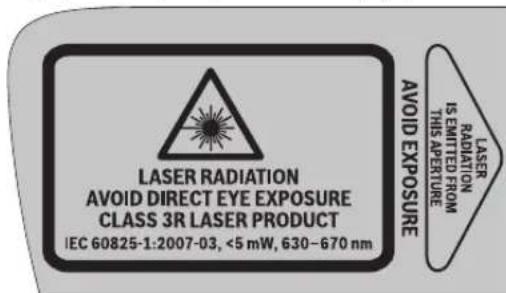
Dokonky TeKcTHa 03HakTe 3a npedypeyBaHe He Ha Bawnt ja3nk, nped npbata ynotpe6a npenenete ro co hcnopaaHnTe HaleHHnHa Bawnt ja3nk.
He ro hacouybaje nacepcknot 3paK Ha
nua Hnn XNBOTHH He norneDhybaJte
BO Hero. OObe Mepeh ypeo cozdaBa
nacepckn 3paun od knaata 3R cnopei
IEC 60825-1. InpkeTeH norIeB
napccknot 3paK - noD ronema
ODdaneHoCT-MOKe Da gn OWTeH OUYTE
Dokonky nacepcknot 3paK Docnee do ouHTe, BeDaW Tpe6a da rH 3aTbOpHe I da ja TprHete rnaBata OJ nacepcknot 3paK.
He rn KopnctTe nacepcknte ouhna kako 3aunTHn ouhna. Nacepcknte ouhna cnykat 3a noo6po npeno3haBahe Ha nacepcknot 3paK, Ho He 3auHTyBaat od nacepckto 3paueHbe.
He rKopnCTe Nacepcknte Oouna Kako Oouna 3a coHue nnnak BO coo6paKaJot. Nacepcknte Oouna He daBaat cenocHa UV-3aHTTA Iro HamaIyBaat npeno3HaBaHbTo Ha 60n.
He BpuTe HnKakBn npOmeHn Ha nacepckNoTypeI.
Параза за земениzzaanaehn.
160992A309|(21.6.16)
Bosch Power Tools


MaKeDoHcKn | 153
MepHnOT ypeD cmee da ce nonpaba camo od ctpaHa ha KBaHnΦnkyBaH CTpyuH eNepcoHAn coOpHnHaHH pe3epBHN DenOBn. CaMo HaToJ hauHn Ke 6nIe TcHyPn BO 6e36eHocTa Ha MEPHnOT ypeD.
H36erHHe TpePfneKcnIe Ond NacepcknT 3paKa Ha Ma3HH NOBpUHH KAKo Ha np. PpO3Op Hnn OrnEgana. OHTeryBaHbeto HA OHTE E BO3MOXHO ND pePfneKcnjata Ha NacepCKNt 3paK.
MepHHOTypeMDoCEKOpHCTNOIHHa, KOH3HaAT da paKaYbaa co Iacepckn ypeDn. CnopeEN 60825-1 M.D.cnaf3haeBeto 3a 6nIOLOWKOTO JeCTBO Ha nacepot HA ouHTe N KOKATA, KAKO nPabNInHaTayNtpeBa Ha IacepCKA3aHTMa 3a H36ERHYBaBe Ha ONACHOCTH.
He pa6oTe co MeHnOtypeB BO OKONHkA KeI NOCTOn ONaCHOcO EKcNIO3HJa, KaE HMa 3aapanHB NteHoCTn, rac Hn npaHnHa. MeHnOtypeC03da B NCKPn, KOH MoKe Da ja 3anaIat npaBtAn nnapeata.
MepHnOT ypeCekoraawNoCTabyBaJte ro,taKa wTo nacepcknte 3paun Ke NOMHyBaat DoCTa Norope HnNOIONY OD BHCnHaTa Ha OHTe. Ha Toj NaHH Ke 6NDete CnryPHN, DeKa Hema Da ce OWTETN OKOTO.
03haeTe ro noneto, kae Ke ce KopnCTH MEPnOtypeD,co cooDBeTHN HALENNHcN 3a npdeynpeyBaBe 3a nacepot. Ha toj haunKe h6erHete, Heno3HaTte Inuca da ce npb6nKat do onachnte 30Hn.
He ro cknadnpajte ro MEPnHOTypeHa MeCTa, KaIe HMaat npHCTan HeOBnacten Hnua. Hnata kon He ce 3aNo3HaEN CO KOpHCTeHTo Ha MEPnHOTypeD, MoKe Da cn HaHTetat Ce6e cn Ha npyTne.
PnKOpHeToHaMepHmOyPeCoKnacaHaNacep 3R,06pHeteBHnMaHHe HaMOXnHTeHaOnHOaHnHn npoHnC. HnpnDpKByBaHTo KOHOBne npoHnC MoKe Da nOBeJe Do nobpei.
IporhKTe ce,nonetoHa IacepckTo 3pauebe da 6nHe HndrnedyBaHo Hn 3auHTneHo. Co orpaHnyBaHe Ha IacepckTO 3pauehe Ha KOHTpOlnpaHn NOnHbKe Tn H36ErHete OwTeTyBaHbTa Ha OuHTe Ha HeOBnactHeHte nua.
Pep6n0KaBa HHTepBHeuJa Ha MePNOType1 (Hapm. MoTaxka, OpKByBaBe HTH.) KaKo H npH HerOB TpaHcnopt N ODPKByBaBe H3BaTe 76 BaTepeHrteOg MePNOTypeI. Pn HEBHMaTeHnO paKyBaBe co npeKInHyBaOT 3a BkNpyBaBe/HckNpyBaBe NoCTOn ONaCHOCT OJ NOBpeHn.
He ja otBopajre 6atepnjata. noctoon onachoct od kpaTOK cnoj.

3aHTe ja 6atepnjata od tonnna,Ha np. od Donrotpajno nNoxyBahe Ha coHcEBN 3paun, oran, B0a Hbra. Nhaky, nocton onacHOCT od ekcnno3na.
Heynotpebehata 6atepnaJa pKxete ja noaneky od KaHcenapnckn CnojYbankn, KnyueBn, XKee3HH napn, KlnHnU, WpaOboN HnDpyrMaH MeTAnn HpeMeTH, WTo MoKe Da npeH3BnKaat NpeMoCTyBaBe Ha KOHTaKTHe. Kpatok cnoj Mefy KOHTaKTHe Ha 6atepnaJt MaKe Da npeH3BnKa H3ropeHnU nnNokap.
PnH norpeHNO KOpHCTeBe,MOKeJa HCTeue TeuHocTa od 6atepnjata.36erHyBajTe KOHTaCt co Hea.Dokonky cnuyajHO JoTe BO KOTAKT CO TcUHOCTa,HCnNAkHete ja co BODoKoONky TeuHOCTa OJDo JE BO KOTAKT Co OvHe, nobapajte NekapcKa nomoi. NCTeueHaTa TEuHOCT od 6atepnjata MOKeJa IpEIN3BnKA KOKHN nPHTaunnn HnH3rOpeHHN.
Dokonky ce owtetn 6atepnjata nHHe ce kopncn npabnnho, od Hea moKe da Hnepe napea. Bhece CBex BO3dyx H DOkONky mHa nobpeHn OndecTe rHa Jekap. NaapeTa MoKe da rHn HapraHn DnHnHn e natnuta.
BatepHte nonheT co nonnau nTo ce npenopauHH NcKnyuHBO od npOn3BOHTeNoT. DOKONky nonHaOT ko e npnaRoTe Ha eEn CoOdBeteH BnD bateHN, ro KopncHTe co dpyn batePN, nocton onacHOCT Ond noxap.
Kopnctete6atepn kon ce cooDBetHa BaHnot Mepen ypeod Bosch.Camo Ha toj hauHH 6atepnjata Ke ce 3aHTN OH onaCHO pneontOBayBahe.
Kophtete camo ophnnnHn Bosch 6atepn co haon Koje Habehen Ha cneuohkaunohata nloka Ha Baunot mepeh ypei. Pn Kophtehe Ha pytn 6atepn, Ha np. mntaun, nctpoen h 6atepn nn He no3natn np03bOHTEN, NOCTON ONACHOCT OJ NOBpeN KAKOM MaTePjAnH NtETn DOKOnky EcKnOInpa 6atepnjata.

He npnncybajte MeHHOT ypeH n
eHnata taba 3a Iacepot 10 Bo 6n3Ha h
nejcmejkep. Marhot Ha MeHHOT ypeH n
eHnata taba 3a Iacepot co3daBaat None,
Koe moKe da ja HapuyuN FyHKnjuTa Ha
nejcmejkepnte.
MepHnOTypeNcENHATA Tabna 3a Iacepot 10 dpXeTe Tn NOdaneky OJ MarHeTCKN HocauHa NoIaTOUH UpeNOCETINBn HA MarHeT. IopaIN BnJaHneTo Ha MarHeTHTe OJ MepHnOTypeNcENHATA Tabna Ha Iacepot MOKe da JoJe Do HEnOBpaTHN 3ary6n Ha NpOaTOUte.
DaneuHcN ynpaByau (GSL 2 Set)

CnTe yNaTcBa Tpe6a Da ce npouHtaa Hda Ce BHMaBA Ha HNB. IO5PO UyBAJTE IN OBNE yNATCTBA.
DaneHHcknOT ynpaByBaCmee da ce nonpaBa cAmo od ctpaHa HA KBaHnHcKyBaH CTpyeH NepcoHa co OPHnHaHN Pe3epBHN DeNoBn. CaMo Ha ToJ HauHH Ke 6nIeTe CnHyPhN BO FynKuHOHaHIOCTa Ha DaneHHcknOT ynpaByBa.
He pa6oTeTe co danueHHckHOT ynpabyBa BO OKONHa Kaede noCTOn onaCHOCT OEGKnNo3Ja, Kaede HMa 3anaHbN TeHcTH, rac nnn npaaHna. daJeHHCKHOT ynpabyBa co3daBa NCKpn, KOI MOKe Da ja 3anaNaT npabTA nn napeata.

154 | MaKeJoHcKn
Onnc ha npon3BOoT mokhocta
Be monnme OTbopete ja npeknonehata ctpaHua co npka3 Ha nobpunHcknot nacep H daeneHHcknot ynpaByBa, n dpkeTe ja OTbopeHa doEka r YoHtate yNaTCTBOTo 3a ynotpe6a.
Ynotpe6a co cooDBeTHa HameHa
TobpunHcNnIacep
MepHnoTypee HameHeT3a npOBepKa Ha paMHocTaHa NOHNHTe NOBpUHHN.
MepHnoType norOeH 3a KopncTeHe BO BHaTpeWe npocToP.
DaneuHnckynpabyBaq (GSL 2 Set)
DaneHHcknOTynpabyBaH aHMeHET3a KOHTpona H noBpuHHCKHeIacePb BO BHaTpeWeH npocToP.
Nlyctpaunja Ha KOMNOHEHTN
HymepnpaheTo Ha cInKHe Co KOMNoHEHTn Ce OJHeCyBa Ha npKa30 Ha NOBpHINHCKNOT Iacep H daJIeUHckNOT ynpaByBaH Ya rpaFnuKaTa CTpaHnla.
TobpunHcN nacep
1I3ne3eHOTBp3aNaacepcknTpaK
2 Hatnnc 3a npedynpeyBahe Ha nacepot
3Дршka
4 PnemHa neKa 3a daneuHcKnOt ynpabyBaq (GSL 2Set)
5 Pnka3 Ha cocto6aHa HanoHHeTOc
6ФИКСИРаБЕHA NOKNOLEOT HA nperpaJaTAta 3a bATEpRuJa
7 Pokloneu Ha npperpaData 3a 6atepjuata
8IpeKHyBaay3aBkyyBahe/NCkLyuBaHe
9 BpTnBO KOnue 3a noDecyBaHe Ha BnCnHaTa
10LenaHaTabla3aIacepoT
Texnukn noaToun
Tobpwncknacep GSL 2 GSL 2 Set
| Броча на дул/аршикп | 3 601 K64 000 | 3 601 K64 001 |
| 3 601 K64 070 | ||
| 3 601 K64 0R0 | ||
| poшая соча осноа со моторен поони далецниста Конtrponа | -● | |
| РавOTно поle 1) | ||
| -бez цILA tabla за ласето | 10 M | 10 M |
| -сысанта за ласето | 20 M | 20 M |
| Точность по пониралье | ±0,3 MM/М ±0,3 MM/M | |
| Тинчинно поуе на самонниралье | ±4° ±4° | |
| Тинчинно вреце на пониралье | <5c <5c | |
| Temпература при pабота | -10°C...+50°C | -10°C...+50°C |
| Temпература при скадиралье | -20°C...+70°C | -20°C...+70°C |
| релатовна влажноct на boздхот макс. | 90% | 90% |
| Класа на пасер | 3R | 3R |
| 1) РавOTно поуе поуе за се hamайни поади неюлени усLOBи на okолината (нлар. діректва зліоженост на сончеви заци). | ||
| Серstочь 6роч 12 на сіпіцфікцциогны піюcka січіи за щасна різдінда півшиот повшинскп пасер. | ||
160992A309|(21.6.16)
Bosch Power Tools


MaKeNoHcKn | 155
| Повшинскп ласер GSL 2 GSL 2 Set | ||
| Тил на ласер | 630-670 nm, <5 mW | 630-670 nm, <5 mW |
| С6 | 1 | 1 |
| Батери (алкални манганскп) | 4x1,5V L R O 6 (AA) | 4x1,5V L R O 6 (AA) |
| Батериja li'thym-johcka) | 10,8 V | 10,8 V |
| Вremетраеные наLABOTa | ||
| -Батери (алкални манганскп) | 15u | 15u |
| -Батериja li'thym-johcka) (1,3Ah) | 15u | 15u |
| -Батериja li'thym-johcka) (1,5Ah) | 25u | 25u |
| Текина сord正常使用 EPTA-Procedure 01:2014 | 1,4 кr 1,4 кr | |
| Димени (Должни x Ширни x Всни) | 210x195x205MM | 210x195x205MM |
| Вид на заштita | IP 54 (заштITA od пави прсань на вoda) | IP 54 (заштITA od пави прсань на вoda) |
1)Pa60THOTONEMOKEJaCeHAMANNOPaDNHeNoBONHUYcNOBHaOKOINHATA(Ha np.DnpeKTHaNIOXKeHOCTHaCOHBeBN3paUN).
Cepnckno 6poj 12 h cneuФkaaHOna TIOUOKA cnyKHa jaCHNeHTNFOKaJna Ha BaHOT noBpuHHcKn nacep.
DaneuHckynpabyBaRc2
| Бpoj на дe/naptnkn | 3601 K69 C00 |
| РаBOTNO NOLE2) | 20 M |
| TempeparaType prn pa6oTa | -10 °C...+50°C |
| TempeparaType prn cknaHpa№ | -20 °C...+70°C |
| БatepNi | 3x1,5V LRO3 (AAA) |
| Текина сordласно EPTA-Procedure 01:2014 | 0,05 кr |
| 2) Работною пое мосяд acse hamamп поради нееловлиу усLOBи на okolnHaTа (нарр. диркTHа Иложеност на сончеви зраши). | |
| Серскnot Бpoj на сецMuКИЗMuHOTа пLOУКa 22 clyЖи за щан иdentMuKИЗMuHЛа на BAшNot мени уред. | |
MOHTaxa
HanojyBaBe co eheprnja Ha nobpunHcknot nacep
MepHnOTypeMoKeJaCeKOpHcTHNlNcoObHuHb6aTePHN NlNcoIHTmJohckn6aTePHN ODS Bosch.
Pa6oTa co 6aTePmH (BnDn CnHa B)
3a pa6oTa co MePHHOTypee Ce npenopayBa KOpHCTeHe Ha anKaHHO-MaHraHcKb 6ateHH.
3a da TCTaBHTe HnH3BaDHTe 6atePNHTe, NOMecyBaHbeto NO BnCnHa MOpA Da Ce DOBeE Bo HajNcKa No3nUJa. PInpToa CBPTe Ro KOnTuE To 9 Ha NoDecyBaHbeto No BnCnHa Do KpaJ Bo npabeC nPOTmBE Ha CTeKNITE Ha YacOBHKnOT.
3a OTBOPaHe Ha NOKNlneoT Ha nperpaData 3a 6atepn7 npHTNCHEte Ha 6nokadata 6 H OTBOpTe rno NOKNlneoT Ha nperpaData 3a 6atepn. CTabe Tn 6atepnTE. PnToa BHIMAbaje Ha NIOBNTe BO cOrnaHocT CO pNkazOT Ha BHaTePshata CtpaHa Ha NOKNlneoT od nperpaData 3a 6atepn.
Cekoraa3amemybajte rncite 6atepnn oedna. Kopnctete camo 6atepnn od eH npon3boDnten co nct kanaunTe.
Dokonky He cTe ro KopHcTene MePHHOType nobeKe BpeMe, mBaTeTe H6aTePhnTe. Dokonky ce noDonro
BpeMeCKnadpaHbATEPHTeMOKeJaKopoDnpaaTNa ceHCnpa3HaT.
Pa60a co 6atepna (BmDn cnka C)
Kopnctete cmo opnrnnHn Bosch nHTym-jOHcKn 6aTePH co HAnOH Koje HabeDen Ha
cneuHkaunohata nnocha Ha BaushoT Mepeyepd.
KopHeTeBToDpyrBn6bAtePmN MoKe Da DoBeDe Do NOBpeHn ONaCHoCT Ond NoXap.
HanomeHa: KopncteHTo Ha 6aTePN HecooDBettn3a BaWHT Mepen ype MoKe Da DOBeDe OI NOrpeHo fYHKUHOHPaHe nn Do OWTeTyBaHe Ha MEPHNOype
Hanomeha:Batejatacencnapyba nony-hanoneta.3a da ja hanoHHte cenocho batejata, nped npbata ynotpe6a ctabete ja ha nonnaHdOeKa He ce HanoHHn eoCHO.
KopHCTeTn cAmo nonHaHTe wTo ce HabeDenH Ha cTpaHnata co onpema.CamO OBne ypeDn 3a nONHeBe ce nOrOHN 3a NtHym-JOHCKATA 6atePjA wTO ce KopHCTN 3a BaHOT MepeH ypeI.
HnHym-jOHCKHTe 6aTePN MoKe Da ce HAnONHat BO cKeO BpeMe, 6e3 da ce HAMAN HNBHnot Pok Ha yNtpe6a.
PpeKnHOT npn nolHebeto He u HaWtetyBa Ha 6atepnjata.
BaTepejjatae onpemeHa co NTC-koHTpona Ha temnepatypata, 1To Do3BOLyBa nonHeBe cAmo Ha TemnpaTpya Mery O ^ C n 45°C. Co Toa ce noCTHByBa dOnr Pok Ha yIOTpe6a Ha 6BaTepejjata.
3a da rH CTaBHTe Hn H3BaHNTe 6atePHTte 23
NOMECTyBaHBeTo NO BHCINHa MOpA Da CE DOBEe BO HajHNCKa
No3njuJa. PnTOA CBPTeTe Ro KOnyTeo 9 Ha NoDEcyBAHbTe NO
BcHnHa Do Kpaj BO nPaBeu CnPoTHBEN HA CTpeKNITE Ha
YacOBHNKT.
3a da rtn CTabnTE 6atepHTe 23 npHTNCHEte Ha 6IokaTata 6 n OTbOpTe ro nokoneoTo nd ppepaTata 3a 6atepn7. PnHTNCHeTe ja HanonHeta TaBepJa do KpaJ Bo npepaTata 3a 6atepn H 3aTbOpTe ro nokoneoT.
Pabota co 1,5-Ah-6atepna: 3a da moxe da ro 3aTbOpnte noknoneou od nperepaata 3a 6atepn7, mopa da ro n3BaIne npdyuWbauO od nehect MaTepejna oB HnatpeHata cTpaHa ha noKnoneou od nperepaata 3a 6atepn.


156 | MaKeJoHcKn
3a da n H3BaHnTe 6atepHnTe 23 npntncHete Ha 6bokaaTa 6
n OTBoperte ro noknoeOTo od perepaTata 3a 6atepn7.
H3BnepeTe H6atepHnTe od npepaTata.
Pnka3 Ha coctoj6ata Ha HanoHHeTOCT
Tpne 3eneHn LED-cjannuKn Ha npka3ot 3a HanaonHeTOc5 ja nokayBaat coctoj6ata Ha hanoHHeTOcHa 6atepHnTe 23.
LED Kanaawret
Tpajno cBeTno 3 x 3eNo ≥ 2 / 3
Tpajno CBetno 2 x 3eNo ≥ 1 / 3
TpaJno CBeTnO 1 x3eIeNo <1/3
TpeKABO CBETNO 1 x3eneHo Pe3epBa
Hanojybahe co eheprnja Ha daneeHHcknot ynpabybay (GSL 2 Set)
3a pa6oTa co daneHHcknO nppaBvau ce npenopauyBa KOpncTebe Ha ankaHIO-MaHraHcKn 6aTePN.
3a da ro tOBpHte kanaKOT oJ nperpadata 3a 6atePHN 20
npHTCHETe Ha mexAHm3MOT 3a 3aknyyBaHe 21 H3BaTe
ro kanaKOT oJ nperpadata 3a 6atePHN. CTabete H6atePHTE.
PnItoa BnHMabJe HA NIOBHTe BO corNaCHOCT co npHKa3OT
Ha BHATpeHATA CTPAHa HA NOKloneoT OJ nperpadata 3a
6atePHN.
Cekoraa 3amemybajte rncite 6atepnn OeJHaaw. Kopnctete camo 6atepnn oeden npon3Bounten n co hct kanaunet.
Iokony He cTe ro KopHCTe daneuHHCKNtO npabyBaau nobKe BpeMe, n3BaTe r6aTeHNTE. Iokony ce noDIOrBOpeMe cKnaHpaHn, 6aTeHNTE moKe da KopoDnpaat N da ce Hcnpa3Hat.
Ynortpe6a
CtabaBe Bo ynoTpe6a Ha noBpuHHcknT Jacep
3aHTTeTo MepHnOypeoBnAuaHdpeKTHo H3noxyBaHe Ha coHueBH 3paH.
He ro h3noxybaje MEPHOT ypeHaekctpeMHN TEMNEPATyH Nn OCUHauu BO TEMNEPATyA. Hap. He ro octabajte Dnro Bpme Bo aBtOMo6HnT. Pnnp RoIeMn OCuaaHn BO TEMEPATyPa, OCTabeTe RO MEPHOT ypeHaJNPBo Da ceakImMaTHnHa, PpeDa ro CTABHe BO ynotpeBa. PnE kCTPEMH NTMEPApyn HnOOCUaHn BO TmEPATyPa, npeun3HOCTa Ha MEPHOT ypeHa MoKe Da CE HApTuH.
H36erhybaje rnydaphtne npebpybaHaTa Ha Mepnnot ypeI. IocnnHte HndBopeuHN BnjuHaJa, Tpe6a da ce npobepn ToHocTa Ha HNBenpaheTo Ha Mepnnot ypeI BO OBnacteHa cepBncha cnuykba Ha Bosch.
NcknyeTe ro mepnhotype3a BpeMe Ha TpaHcnpoptOT. Pn HcknyuBaHaTe,ce 6NoKpnaOCunnpaKaTa eHHua, koja 6n ce oHTtna pnp nHTeHNBn DBNXeHa.
IocTabyaBaHeHaMePHNtypeA
IocTaBete ro MepHnOT ypeHa uCBpTa noDInora Ha noDHaT a nobPunHa koJaTuTo Tpe6a Da ce npOBepn.
ToHocTa Ha HnBEnIpaHbTo MoXe Da 6nIe NOD BnJaHHe Ha OKoHnHaTe TEMepaTypa. Oco6eHo TEMpePaTpHte pa3nKu
KoN Ce DnKnat OJ NOOT HArOpe MOKeJa Ro IpeHacOaT NacepcknoT apak. BnJeekn TempepaTyPhnte pa3nKnCe HajroEmn BO 6bn3nHa Ha NOOT, MePHNOrYpeTpe6a Cekoraaw Da ce NoCTaByBa BO cpeHnata Ha NODHa T nobPunHa KoJAwTO Tpe6a Da ce npOBepn.
BknyyBaBe/hcknyyBaBe
3a BknyBaBe Ha MEPHOT ypeD npHTncHEr o npeKHyBaOTo 3a BknyBaBe/NCkyuBaBe 8 Bo no3njuJa "On". BeHaN o BknyyBaHeto, MEPHOT ypeD HcnyTa nacepckn 3paun Ond hne3HNTe OTbOpn 1.
He ro hacovybaje nacepcknot 3paK KOH Nuaa HnXHBOTHN (oc6eHO He BO BnCHHa Ha OHTe), HneNORNEHyBaTe DnpeKTHO BO Hero (dypn Hn OD ronemaOdaaneuhoct).
3a Ncknyybahe Ha MEPHNOTypeI npHTNCHETe I npeknHyBaOT 3a BknyyBaBe/HcknyyBaBe 8 BO no3njuJa "Off".PnH NcknyyBaBe,OCuNNpaKaKata eDHHca ce 6boknpa.
Iokony MepHnoT ypeH He ce DmKn OkOy 30 MIn. OHN. He CE KOHTpOJInpa npeky daneuHcN ynpabyBau, Toraaw Toj ABToMaTCKe HcckLyUyBa 3apadn 3aWHTHa 6aTePnHTe
No ABtOMaTCKOTO HcKnyuBaHe, HcKnyeTe Ro MEPHnOTypeJ HA npeKHyBaOTo 3a BkLyuBaBe/HcknyuBaHe 8 n no NOTpe6a NOBTOHO BKnyeTe ro.
GSL 2 Set: No aBtOMaTCKOT NCKNpyBaBe, MOKe NOBTOpHO Da r BO BKNyUHTe MEPHNOYpeI CO pNHTnCKaHBe Ha HEKoe KONue Ha daneuHcKHot ynpaByBaY.
He ro octabajte BknyeHnOt MpeH ype63 Hn30 np ncknyeTe ro no ynotpe6ata. pynte nnca MoKe da ce 3acnenat od nacepckhot apK.
Pn npuekopybahe Ha hajbcokata do30b0neha pa6oHa Tempepatya on 50 ^ C ce ncknyBa 3apaa3aunTHa naacepckata dnoa. OTKako Ke ce onaH, MePHNOT ypee NOBTOPONoIrotBeH 3pa6Ota MoKe OHOBO Da Ce BKNyH.
Pa6oTa co 6atePnJa: IInmym-Johckata 6atePnJa e 3aunTeHa co „Electronic Cell Protection (ECP)" od dna6bHcKp npa3Hebe. Jokolky 6atePnJa e Hcnpa3HeTa, MEPnHOT ypeD ce NcknyuBa co 3aunHTeH npeKnHyBaU. Jokolky MEPnHOT ypeD abTomatckn Ce n3racn nopadn Hcnpa3Heta 6atePnJa, NcknyuTe fo co npeKnHyBaOT 3a BknyuBaBe/HcknyuBaBe 8. HanonHete ja 6atePnJa nped da fo BKnyuHte NOBtropHo MEPnHOT ypeD. Hnaky 6atePnJa To Moke da CE OwtETn.
Hbennpahe Ha MepnToype
ABTomathkata 3a HnBEnHpaBe aBtOMATcKn HnH3paMHyBa HepaMHNHTe BO NOpTe HA cAmOHbENHpae ± 4^ HnBEnHpaBeTo e3aBpSeHO ToM nacepckte IHHn He ce DnHKat NOBeKe.
DOKOJIky He e BO3MOKHO aBtOMaTcKO HbENIPAhe,HaNP. 6ndejkn NpIorata Ha MEPHNO typeoCTanyBa NOBeKe o4° OXOpN30HTanata,NaCEPCKHe IHHIN TpenKaAT.
IocTabete ro MEPHNOt ypeJ xOpH3OHTaJIHO nOueKaJTe ro camOHbENHPaHBeTo. IITOM Ke ce hajde MEPHNOt ypeJ BO noneto Ha camOHbENHPaHBe oJ ±4°, nacepckte liHHn CBetat HEnpeKHaTO.


MaKeNoHcKn | 157
PnBn6paunn npomeHa nnojokbata 3a BpeMe Ha
pabotata, mePHNOT ypeI NOBTOPO ce HNBENIPA
ABTOMATCKH, a pni nnoIeMn IpomeHN Ha noJIOXbTa MOxHO
eHa dpyra BNCnHa. IIO NOBTOHPo HNBENPAhe, npOBepTe
rO NOKPBAHcToHa DBte NaCEPCKn HINHn HA pepepeHTHa
tOuKa (BnDn, M3paMHyBaHe Ha mEPHNOyPeI NO BnCnHa*,
ctpHa 157), 3a da rH n36BerHeTe rpezkIne BO BnCnHa.
H3pamHyBaBeHaMepHnOtypeDNoBChHa
MepHnOT ypeE emtnpa DBe nacepckn nnHnKoNc BnINbHa pactojaHne od okony 50 cm nped mepHnO anat Ha noDhata nobpuHna. NInHnTE MOpA da ce nokOnybaaT ha OBaa pepepeHTHa TocKa, Ha KooJaTo npBnOt nat 6ea BnINbHa noDHaTnOBpuHna. PnTOA CBPTe Ro konUeTo Ha 9 Ha NoDEcyBaBeTo NO BCnHa BO Odn. BO npabeC CnpOTNBEN HA CTpeKNte Ha YacOBHNKOT, DoKe Ka He CE npEKNOTdBEte nacepckn nnHnHa pepepeHTHa TocKa H He CE BnDc Camo EdHa nacepcka nnHJa.
Iokky DBeTe Nacepckn HnHn He MoKe Da Ce npeKlonat Co BpTeHe Ha NoDecyBaBeTo NO BnCnHa, Toa 3NaHn DeKa MEPnHOT ypeE e 3NaHTeHNOBcKO HnN NOHNCO OJ NOHaTnOBpHnHa. NocTaBeTe Ro MePHNOT ypeH aDpya TOka HA NoHaTa NOBpHnHa CO NOMaBA BnCnHcKa pa3nKa H TamY IpeKnloTe rDBeTe Nacepckn HnHn.
CtabaBe Bo ynoTppe6a Ha daneeHHcknOt ynpabyBaq (GSL 2 Set)
3aHTETe ro daneyHHCKHOT ynpabyBaO od Bnara HnpeKTHo h3noxyBaBe Ha COHueBn 3paun.
He ro hnoxybajte daneyHHcknot ynpaByBaH aektpemn TMnepatypn HnN ocunauu BO Temnepatypata. Hanp. He ja octabajte doIro BpeMe BO abTomobnIOT. Pnir gonmoucnauu BO temnepatypata, octabete ro daueHHcknot ynpaByBaH HajnpBO da ce akImmat3npa, nped da ro ctabte BO ynTope6a.
CeIIOEkaHMaIOBONHO HANOH Bo 6aTePnJaTa, daNeuHckNTo ynpabYBaue noIroTBeH 3a pa60ta.
CnHaHNTe Ha daneuHcknoYnpaBvau Tpe6a Da DocTHnHaT
do npHeMaHaNeKa 4 Bo DNpeKTeH nPaBeu O hAnpei Koco
OoPe. DOKONky daneuHcknoT ynpaBvau He MoKe Na ce
HacOuHnDpEeTH Ho npHeMaHaTe Nke, Ce HAmanyBa
paBtoHTo NOpaue. Co pePfekCNH Ha CnHAnOT (HaNP. Ha
sNDobTe) DoMeTOT MoKe Da ce NoOp6pn i pNnHnDpEeTH
CnHAn.
BknyyBaHbetoHa MEPnHOT ypeCo daneuHcKn ynpaByBaue BO3MOxHOpynNo aBTOMaTCKOTO NCKnyyBaHe Ha MEPnHOT ypeD,doKoNky pKeKNHyBaHT 3a BknyyBaHe/NCknyyBaBe 8 c ce yUte BO no3uJaOn". HcknyyBaHbeto Co daneuHcKn ynpaByBaue He e BO3MOxHO.
IpoceHa MepeHe
PauHObBpTeHe (GSL 2)
CBPTe ro ropHnOT den Ha MePHNtypeHa MeCTO KOeHTO cakate da ro npOBepHTe. IIO BPTeHbTo NOeKajTe,doEka He ce H3HHBENHPa MePNOTypeI NacepCKITE LHHNHe CE DnKATNoBeKe.DpyrToraI npOBepTe daNNce npeKnOnyBaat nacepCKTe LHHN.
ABTomatcko BpTehe (GSL 2 Set)
CbptTe ro ropHnOt den Ha MePHnOTypeD co NOMoH a
daeneHHCKNt ynpabyBa, 3a da ja npOBepIte NOBpHHHaTa.
He e BO3MOxHO paHNO BpTeHe.
Mozja n3bnapte nomery cneHnBE bNIOBn ha potaunja:

PnHTNCHETe ro KOnyTe 19,3a da cTApTyBaTe 6p3a, KOHTNHynpaHa poTaunja Bo npaBeu Ha CTpeKNte Ha YacOBHHKOT. Co OJHOBO npHTNcKaHe Ha KOnyTe 19 poTaunjata 3abpyBa.

PnTnCHTe Ro KOnUeTo 14,3a Da cTapTyBaTe 6p3a, KOHTnHynpaHa poTaunJa BO npaBeu CnpOTHBEN Ha CTpeKNHe Ha YacOBHKnOt. Co OndHO BnTnCKaHb Ha KOnUeTo 14 potaunjata 3abPpsiBa.

PnTCHETe ro KOnHcTe 18,3a da cTapTyBaTe 6aBHa,KoTHnHynpaHa potaunJa BO npabeu Ha CTpeKNHe Ha acOBHNKOT. Co odHOBO npTHCKaBe Ha KonHcTe 18 potaunjata 3aBpUyBa.

PnHTNCHETe ro KOnyTe 15,3a da cTapTyBaTe 6aBHa,KoTHHyHpHa potaunja Bo npabeu CnpOTHBEN Ha CTpenKHe Ha YacOBHKOT. Co OHOBO nPnTNCKahe Ha KOnyTe 15 poTaunjata 3aBpUyBa.

PnTCHETe ro KOnyTe 173a eHNOKpaTHa, KpATKa potaJb BO npaBeuHa CTpeKNHe Ha YacOBHNKT. 3a NoHATAMOHNoEHNHeUHO DBHXKeHe, PnTCHETe ro OHOBO KOnyTe 17.

PnTtCHETe FO KOnyTe 163a eDnOKkPatHa, KpataKo potaJia BO npaBeue CnpOTHBen Ha cTpENKe H acoBHNKT.3a NohATAMOHNOeINHeuHO DBNKHe, PnTtCHETe FO ODHOB KOnyTe 16.
IpoeHa ha pe3yntaHTte oMpeheBeto (BnD CnKn D-G)
IbeteNacepcknINHHINNOKaKyaBaT,daHNOBpHnHaTaJeKn Ha nCTa BNCnHa KAKo INpepeepHTHaToUkA (BNi N3paMHyBaBe Ha MEPnHOTypeNo BnCnHa",cTpaHa157):
CITE TOUKN HA KOHHTO DBeTne NacepCKN HNNH NexkatnpeknnyBajKn Ce eHa npEky Dpyra, Ce Haoraat Ha nctaBNCnHa KAKo pepeepHTHata Toyka.
-ДOKOKIy DBete NacepckN NHHN CE BUNNBn EHa NOKpaj Dpyra NIN CE NpeKHaTH, ToraW BNCnHata Ha NOHaTaNOBpUHa Ha OBA MecTo OTCTaYBa OJ pepepeHTHaTATOka.
3a da ro hMepHe oTcanyBaHbeto Ha noHaTa NOBpWnHa, noctabete ja cenHata Tabna 3a Iacepot 10 Ha MeToTO koeWTo Tpe6a Da ce npOBepn. CbpTe Ja cENHata Ta6Na Ha nacepot, Taka WTo neBata Nacepcka NINHa Je NOMHyBa ToHO Ha NeBata pepepeHTHa INHJa Ha cENHata Ta6Na Ha nacepot. IomecTe Ro rOpHnO Det H cENHata Ta6Na Ha nacepot Harope Odn. HADony, Doeke BpOT 11 Ha cENHata Tabna Ha nacepot He Hanere Ha MeCtOTO KoeWTo Tpe6a Da ce hMepu. Ha no3HniJata Ha deChata Nacepcka NINHa Ha cENHATA Tabna Ha nacepot MoKe da ja npOCHtate BmCNHCKata pa3NkA NOMeY pepepeHTHa TOKa H MepHata TOKa BO MNIMMeTpH.

158 | MaKeIOnHcNk
IokonydeteIacepcknHHNcceOndaneyuBaatHaNoDHaTa NOBpHnHa eHaOD npyra BO KOHCTaHTe aroJ,Toa 3NaHn DeKa NoDHaTaNOBpHnHa eNoHaHn6.
Cobetnpa6oTeHeto
BHHMabajte cetaata hnpHa ha nacepcknte nnHn da ce npknonyBa eda npky dpyra. HnHnata Ha nacepcknte nnHn Ce MeHyBa co ondaneyBaheTo.
TpaHcnpHa MePHHOTypeI
PaKaT3 nOMa3a nOleCen TpaHCnOpT Ha MePHNtype.
No notpe6a, npeKnoneTe ja paKaTa Harope.
Nacepckn ouyna (onpeMa)
Iacepckte Ounna ja hnntpnpaat OKolnata CBetnHa. Ha Toj NaHH UpbHOTo CBETNO Ha Iacepot N3rpeJa NocBETNo 3a OKOTO.
He Hn Kopnctete Nacepcknte Ounna KaKo 3aHTTHOounna. Nacepcknte Ounna cnjkaT 3a noD6po npno3HaBaBe Ha NacepckNt 3paK, Ho He 3aHTHTyBaaT od, NacepCKTO 3pauebe.
He HN KopHCTe NaCEpCKNTe OunHa KaKo OUnHa 3a coHnce Hn NAK BO COOpaKaJOT. NaCEpCKNTe OUnHa He daBaat CEloCHA UV-3aWHTA Hr Ho HaMaIyBaat npeno3HaBaHbETo Ha 60n.
HanomeHH 3a onTHMaHIO KOpHeBa Ha BaTepeHHTe
3aHTe ja 6atejata od Bnara n Boda.
Cknnapjte ja 6atepnjata BO rpaHnHa TeMnepaTpyoO 0^ Cdo 50^ .He ja octabajte 6atepnjata Ha np.Bo ABTOMObNt IeTHo Bpeme.
CkpaTeHOTo BpeMe Ha paOta No nonHeHTo NOKaKyBa,NeKa 6aTepnjatae nnotpoSha Mopda Da ce 3aemen.
BHHMaBJte Ha HAnOMeHTe 3a OTCpaHyBaHe.
OdpKyBaBe H cepBnC
OdpxgyBaHe n uHCTeHe
Pep6HnKakBa HHTepBHeuJHa Ha MepHnoT ype1 (Hanp. MoTaxka, ODPxByBaBe HTH.) KAKo H npH HerOB TpaHcNopt H ODPxByBaBe H3BaTe FbATEpHnte OD MEPHnoT ypeI. Pn HeBHmAteJIHO paKyBaBe co npeKHyBaOT 3a BkNyUyBaBe/HckNyUyBaBe NoCTOn ONaCHOCT OJ NOBpei.
Cknapjte ro npaHcnpoptpajte ro nobpuHHcknoTnacep cmo BO hcnopauahnOt kydep.
IocjoJHOOpxyBajTe jaHCTOTATAHaNoBPsiHHcknTnacep HdaJeHHCKNtYnpaByBa.
He nnoTOnyBajTe NoBpuHckNt Nacep H daNeuHckNTo ynpaByBaB BO BDA HnDpyTH TeHuOCTn.
H36pnueTe Hn HeNCTOTnHTe CO BnAaHa MeKa Kpna. He KopHcTeTe CpeCTBa 3a YnCTHe Bn PaTbOpn.
PeIOBHOHCTETeTINOBPIHHHTEOKOJN3NE3HNOTOTBOPHaIacepOt HIPnTOA BHHMABajTe Ha BlaKHeHcTa.
Dokolny NOBpuHHCKNt Nacep Hn DaneuHckNt ynpaByBaCe paCnne Hn NOKpaj rpnKnBOTo OdpXyBaBe BO CORNaCHOCT Co HANOMEHTE Ha npO3BOIDNTOT,NONpaBkata
Tpe6a da ce H3BpuH caMo oD ctpaHa Ha OBnacteHaTa cepBncha cnYk6a 3a Bosch-eneKTPuHn anatn. He rO TBopajTe NOBpHnHCKNt Nacep n daJeHHckNt ynpabyBa CaMn.
3a CNTe npaaHbHa HapauKn Ha pe3epBHN denobn,Be MoNMe HabeTe ro 10-ncfpeHHOT 6poj od CneuHkaHOnHa IIOUka Ha NOBpuHcKnOT nacep N daueHHcknOT ynpabvBa.
Bo cnuyaj da tpeba da ce nonpabn, npate ro nobpuHHcknot nacep Bo kyepoT.
CepBncha cnyXba H COBETn npN KopNCTeHe
CepBnchata cnyk6aKe odroBOpn Ha BaunTe npaaHb BO Bpcka co nonpaBkata n OndjyBaBeTo Ha Baunot npon3BOKako n pe3epBNHTeNoBH. EKnno3HBEN uptexn Hfopmaun 3a pe3epBHN denOBn Ke HajndeHa:
www.bosch-pt.com
TMMOTa coBeryBaBe npn KOpHCTeHe Ha Bosch Ke Bn NOMORHe DOKONky MAte npaHaBa 3a HauHTe npOn3BOuN onPema.
MaKeDoHja
Д.Д.Енктпс
CabaKobayek47H,6poj3
1000 Ckonje
E-nouta: dimce.dimcev@servis-bosch.mk
HHTepHeT: www.servis-bosch.mk
Ten./fəkɑc:02/2467610
Mo6.:070595888
TpaHcnpT
JHym-jOHCKHe 6atepn noDneKat Ha 6apaBaTa Ha 3aKOHOT 3a OAnCH MATEpNJann. BatePHTe MoKe da ce TpaHCnOpTnpaAT cAmO od CtpaHa Ha KopNCHKOT, 6e3 Notpe6a oD DonONHtENH KBaHnΦkaun.
Pnpnpehoc Ha nctte od ctpaHa TpTe Nua (Ha np. BO3Dyuwen TpaHcnpot HnN WneDiuJa) HeoNxoDo e da ce BHMaba Ha CneuJanaHte NaOMeHN Ha aBaNanKaTa O3HAKnte. Bo TakOB cnuyaj, npnr noDroTobkata Ha npatkata Mopaa Ce nobNbKa ekcnepr 3a onaChn CynCTAHU.
TpaHcnpOpTpajTe rH 6aTepeHnTe cmo DOKoKny KyKniuTeTo e HeouTeTeHO.3aEneTe rH OTBopeHnTe KOHTKn H CnakyBaJte ja 6aTeepNJata Ha ToJ NaHnH ITO HeMa Da ce DnBxN Bo am6aIaxkata.
Be monime BHHmabajte Ha eBentyaHHTe DOnonHHTeHNHaHNOHAHNI npOnnC.
Otrpahybahe
IobpHnHckNtIacep,daJeHHCKNtUynpaBvBa, 6aTePnHTe,OnpeMaTa nAm6aJaxnTe Tpe6a Da ce oTcPaHAT Ha ekONoOuKn npHaTnB HauHH.
He ro fprajte noBpuHcknT nacep, daeneHHcknOT npabyaB u 6aTePnnte BO domaunata KaHTa 3a ry6pe!
Srpski | 159
Cama 3a 3emjn BO pamkn Ha EY
Cnopee ebponckata perynatmba
2012/19/EU enekptnHHte yepd nTo ce
BOH yNtpe6a HdepekTHne Hn
HcKOpncTeHNte 6aTePNn Cnopeed
perynatbata 2006/66/EC mopa odJeHno
da Ce co6epaT Na da peuNKnPaat 3a
NoBtphya yNtpe6a.
BaTepeHn:
JINTHYM-JOHCKH:
Be monnme BHHmabajte Ha HAnomeHnTe Bo den ,TpaHcnpT, CtpaHa 158.
Ce 3aDpxyBa npaboto Ha npomeHa.
Srpski
Uputstva o sigurnosti
Povrsinski laser

Morate da procitate i obratite paznju na sva uputstva kako bistie sa altom radili bez opasnosti i bezbedno. Nemojte da dozvolite da plocice sa upozorenjima budu nerezumljive. DOBRO SAÇUVAJTE OVO UPUTSTVO I PREDAJTE GAZAJEDNO SA ALATOM, AKO GA PROSLEDUJETE DALJE.
- Oprez - ak se koriste drugi uredjazi za rad ili podesavanje od onih koji su ovde navedeni, ili izvode drugi postupci,mez ovo voditi eksplozijama sa zracenjem.
Merni alat se isporucje sa dve tablice sa opomenom (u prikazu mernog alata označene na grafickoj stranici sa brojem 2).
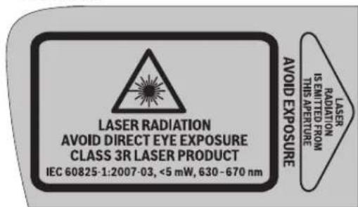
Ako tekst tablica sa opomenom nije na Vasem jeziku, onda ga prelepite pre prvog pustanja u rad sa isporucenim nalepnicama na Vasem jeziku.
Ne usmeravajte laserski zrak na osobe ili zivotinje i n gledajte samu laserski zrak.Ovaj merni alat proizvodi lasersko zracenje klase lasera 3R IEC 60825-1.Direktan pogled u laserski zrak -cak i sa veceg rastojanja -moze ostetiti oko.
Ako lasersko zracenje dode u oko, morate svesno da zatvorite oko i da glavu odmah okretene od zraka.
Ne koristite laserske naocare za posmatranje kao zastitne naocare. Laserske naocare za posmatranje sluze za bolje prepoznavanje laserskog zraka, one ne stite od laserskog zracenja.
Ne upotrebljavaje laserske naocare za posmatranje kao naocare za sunti iu putnom saobracaju. Laserske naocare za posmatranje ne pruzaju punu UV zastitu i smanjuju opazanje boa.
Nemoje da vrsite promene na laserskoj opremi.
Neka Vam merni alat popravija strucno osoblje i samo sa originalnim rezervnim delovima. Time se obezbedjuje, da sigurnost ernog alata ostaje sacuvana.
Izbegavaje refleksiju laserskog zraka na ravnim povrsinama kao sto su prozori i ogledala. I preko reflektujuceg laserskog zraka moguce je ostecenje ociju.
Sa mernim alatom bi trebale da rade samo osobe koje su upoznate sa radom lasersikh uredjaja. Prema EN 60825-1 spada u to izmedju ostalog i szananje o bioloskom dejstvu lasera na oci i kozu kaoi pravilna upotreba zašite od lasera i otklananje opasnosti.
Ne radite sa mernim alatom u okolini gde postoji opasnost od eksplozija, u kojo se nalaze zapaljive tecnosti, gasovi ili prase. U mernom alatu se mogu proizvesti varnice, koje bi zapalite prasinu ili isparenja.
Stavite merni alat uvek takto, da se laserski zraci pruzaju daleko iznad ilisip odvisine ociju. Tako je obezbedjeno, da ne dodje do ostecenja ociju.
Oznacite područe, u kojem se upotrebljava merni alat, sa pogodnom tablicom sa opomenom Laser. Tako izbegavate da strane osobe ne dodju u područe opasnosti.
Ne cuvajte merni alat na mestima, na koja neovla-scene osobe imaju pristup. Osobe koje nisu upoznate sa radom mernog alata, mogu sami sebe povrediti i povrediti druge.
Obratite pañnju kod koriścenja mernog alata sa klasom lasera 3R na moguće nacionalne propise. Nepridžavanje ovih propisa moze uticati na povrede.
Pobrinite se za to, da je podruce laserskog zracenja pod nadzorom i zasticeno. Ograničavanje laserskog zracenja na kontrlisano podruce izbegava oštecenja ocju stranih osoba.
Izvadite akumulator odnosno bateriju pre svih radova na mernom alatu (na primer montaizi, oderzavanju itd.) kao i kod transporte i cuvanja mernog alata. Pri slucaj-nom aktiviranju prekidaça za uskljucivanje-isključivanje postoji opasnost od požara.
Ne otvarajte akumulator. Postoji opasnost od kratkog spoja.

160 | Srpski

Zašitite akumulator od toplote, na primer i od sunčevog zračenja, vatre, vode i vlage. Postoji opasnost od eksplozije.
Drzite nekorišeni akumulator dalje od kancelarijskih spajalica, novčica, ključeva, eksera, zavrtanja ilidrugih malih metalnih predmeta, koji bi mogli prouzrokovati premoscavanja kontakata. Kratak spoj izmedju kontakata akumulatora moze imati za posledicu sagorevanje ili požar.
Kod pogresne primene moze tecnost da izadje iz akumulatora. Izbegavaje kontakt sa njom. Pri slucajnom kontaktu isprati sa vodom. Ako bi tecnost dosla u oci, pozovite dodatno ilekarsku pomoc. Tecnost akumulatora koja izlazi moze uticati na koze nadrazaje ili opekotine.
Kodostećenja inestručne upotrebe akumulatora mogu izlaziti pare. Dovodite sveži vizduh i potrazite kod tegoba nekog lekara. Pare mogu nadraziti disajneputeve.
Punite akumulatore sono u uredjajima za punjenje, koje je preporucio proizvodja. Za uredjaj za punjenje, koji je pogodan za odredjenu vrstu akumulatora, postoji opasnost od pozara, kada se upotrebljavaju sa drugim akumulatorima.
Upotrebljavte akumulator samu vezi sa VaSim Bosch-mernim alatom. Samo takse akumulator moze zastiti od opasnog preopterecenja.
Upotrebljavaje samo originalne Bosch-akumulatore sa naponom koji je naveden na tipskoj tabici Vaseg mernog alata. Pri upotrebi drugih akumulatora, na primer imitacija, doradjenih akumulatora ili stranih fabrikata, postoji opasnost od povreda kao i stete na predmetima od akumulatora koji moze eksplodirati.

Ne donosite merni alat i lasersku tablicu sa ciljem 10 u blizin pejsmejkera. Preko magneta mernog alata i laserske tablice sa ciljem se proizvodi polje, koje moze ošetiti funkciju pejsmejkera.
Držite merni alat i lasersku tablicu sa ciljem 10 podalje od magnetnih nosilaca podataka i uredjaja osetljivih na magnet. Delovanjem magneta mernog alata i laserske tablice sa podacima mogu se nepovratno izgubiti podaci.
Daljinska komanda (GSL 2 Set)

Sva uputstva se moraju citati i na njih obracati paznja. CUVAJTE OVA UPUTSTVA DOBRO.
Neka Vam daljinski komandu popravija strucno osoblje i samo sa originalnim rezervnim delovima. Time se obezbedujude da ostane sačuvana funkcionalnost DALiinske komande.
Ne radite sa daljinskom komandom u okolini ugrozenoj eksplozijom, u kojoj se nalaze zapaljive tecnosti, gasovi ili prasine. U daljinskoj komandi se mogu proizvesti varnice koje pale prasinu ili isparenja.
11111111111111111111111111111111111111 50 aaaa aaaa aaaa aaaa aaaa aaaa aaaa aaaa aaaa aaaa aaaa aaaa aaaa aaaa aaaa aaaa aaaa aaaa aaaa aaaa aaaa aaaa aaaa aaaa aaaa aaaa aaaa aaaa aaaa aaaa aaaa aaaa aaaa aaaa aaaa aaaa aaaa aaaa aaaa aaaa aaaa aaaa aaaa aaaa aaaa aaaa aaaa aaaa aaaa aaaa aaaa aaaa aaaa aaaa aaaa aaaa aaaa aaaa aaaa aaaa aaaa aaaa aaaa aaaa aaaa aaaa aaaa aaaa aaaa aaaa aaaa aaaa aaaa aaaa aaaa aaaa aaaa aaaa aaaa aaaa aaaa aaaa aaaa aaaa aaaa aaaa aaaa aaaa aaaa aaaa aaaa aaaa aaaa aaaa aaaa aaaa aaaa aaaa aaaa aaaa aaaa aa
(GSL 2 Set)
a aag aag aag aag aag aag aag aag aag aag aag aag aag aag aag aag aag aag aag aag aag aag aag aag aag aag aag aag aag aag aag aag aag aag aag aag aag aag aag aag aag aag aag aag aag aag aag aag aag aag aegaaaegaae 100000000000000000000000000000000000000000000000000000000000000000000000000000000000000000000000000
wulalac
GSL2) 5g 10000000000000000000000000000000000000000000000000000000
(GSL 2 Set)
jgabwglgllwqg jgs
jlaabwglgglggl
.1s0
:agglgglgglg
jaou ydlac 19 jll bdo lal !dullylo aoluyg

0juaa yag aalac 14jjll bdo 1. aclll ylac aso alt jssa aag .uJgJJyai (14jjllbc

0jmo uagulac 18 jllbdoi bdoi n .aeuui jlae asa oaiy aibg .uigjll gai siao 18 jjll

Bosch Power Tools 1609 92A 309 (21.6.16)
wla o
aaij lce aaa9 ygcjoll abwll lc wlaol osc qai
gagwll aLc jgj gaball oJal all Jn!
glgai jol n ao jlll oJal lalai gj
ngsi jolll uI Iaog. jllleew wlcI Ll
uui I lois gai nlo jao 1c Ie Lcl
daqgaj glawll caiaio gwlal ox
Labyg
aiao gai jy wai ooc uoi j 10
wai ooc . "On" jall 8 labg uaii
.1juiu ca jui aai i gaiu uaiu
gulgl gl yawll lgc jull elaw dgi
lcluaiuy jblg (naiell glajl lc laow
(5e jc Gg) jull eaw
lablg uusll glao g ywll ooc lab! jno .labz xic g yll oag uaw. "Off" jsall 8 jlaa abwgl qasill g wll oac uay pui n! .lali no labi g, yj0 30 oxal yc pssll .psll g tulll aial alqoi .lablg uusll glao abwgl wll ooc labi sic syl ojo dgs lalab se 8 .ogj
Jl qalbl s y wll osc Jw w j elcay :GSL2 Set .sucpall jj jg lbc ball 1a no aqjpo jgs Jull wll wll ooc JJ 4 lac! pui .Lglasil sy wll ooc gblg .jll Eeawy uai
gall jgl gj 15k a
. jll plao ag 50C aall agaall
sag sill ssu wll osc wai
. xic qw wcl
:gsall go
gai jai i gai i gai gai jai Electronic Cell Protection/ aigui IaIJI aigai gaiu gai JiaIgai JiaIgai JiaIgai JiaIgai JiaIgai JiaIgai JiaIgai JiaIgai JiaIgai JiaIgai JiaIgai JiaIgai JiaIgai JiaIgai JiaIgai JiaIgai JiaIgai JiaIgai JiaIgai JiaIgai JiaI gai JiaIgai JiaIgai JiaIgai JiaIgai JiaIgai JiaIgai JiaIgai JiaIgai JiaIgai JiaIgai JiaIgai JiaIgai JiaIgai JiaIgai JiaIgai JiaIgai JiaIgai JiaIgai JiaIgai Jia I gaiJia I gaiJia I gaiJia I gaiJia I gaiJia I gaiJia I gaiJia I gaiJia I gaiJia I gaiJia I gaiJia I gaiJia I gaiJia I gaiJia I gaiJia I gaiJia I gaiJia I gaiJia I gaiJia I gaiJia I gai
1 8. 8abg lglaoaogwaiol oclal calu .waiol osc
wulai o s d ayw
Jn Jn Jn Jn Jn Jn Jn Jn Jn Jn Jn Jn Jn Jn Jn Jn Jn Jn Jn Jn Jn Jn Jn Jn Jn Jn Jn Jn Jn Jn Jn Jn Jn Jn Jn Jn Jn Jn Jn Jn Jn Jn Jn Jn Jn Jn Jn Jn Jn Jn Jn
auiuugwlljublg JsuWuai oocuii uaiuol 0c alg j99 jaoo Lsuy jull aai w 4+ uui iui uguil lso
g 1J Jw wll oagw oI a
eai jn i! I, uanuill uagwgl Uaia Jy
ggi. gkiagwgl Uaia CkUcii
agw"gj) agwll oLc! ayaejo abai jlll y
eai jx 197 aalil "wlaall eay
6 JIJI Ic b2a 23 pJll SJS
pJall gJ. JI17 Ujll Oa aLac dJg
ao slalld JUJJUJIJI UJUJIJI UJUJIJI UJUJIJI
:clw 1,5-Ah pSj
1y 7 UjUjll oJgLg jI gbiw y J
OjS uBj y IaIuI cIgJl dssall Jj
. UjUj
6 1aJIUc baiu u23 pJlI aJ SJI Uc pJlI ywI .L7 UjUJI Iy.
Jn
5JwIaIgawagaiIiIaiaIgawagaiIg 23pSajglUuluIwA
| dssu | jia |
| 3/2 ≤ | jia x 3 jaiu o g |
| 3/1 ≤ | jai x 2 jiuu o g |
| 3/1 < | jai x 1 jiuu o g |
| jiaiial | jai x 1 iai s o |
JJI JUO UJU OJUOLAWUUG
gawj gll jslal 1 wlaal oocn jjogg
JllolawlU.
JyIgIgIgIgIgIgIgIgIgIgIgIgIgIgIgIgIgIgIgIgIgIgIgIgIgIgIgIgIgIgIgIgIgIgIgIgIgIgIgIgIgIgIgIg
amjgaguaol
oe pssuiw sic daaaiol aibgll poiae j
pksuul 3R juii aai u
.
eai!JoojwgiawjolaojUJI
aaijlll jll ljcjjllgawjnnj
.1jai jolawl 5J Jn nn nll l joi j
jlll 1e jUJUJIgIpSJIJI
aiall (aill:la) uall 5c lc Joc
aJbJusuLgagLaicLg(.1g
JU 1
.3g4
.uaai Juaicbsuuiy
jaii I aq Jai jai jai jai jai
jUJgIIO JpaWU JuaWU aW
Jaaai Jaa UssuagbglgLoJIg

jc 1s jssaaa aai jll sajll jlc b
jlaJg aui Jgai I gai I gai
6JdJdJgJgJgJgJg
bcU. uunolaluai J 5j
g|g|j|J|S|g|g|S|g|S|g|S|
JU
pdaaiwlaicpsjllno jilwuljui
gaiaiy jill jwll ojai bao psljll
J 1
go qoaii pui pSjall u o eegil aannll
.0s1jol joo jEgi
w g wg o go u lai ly bao jol pss
JSSALLGajgillLgucugaaabllO
bbllll b
#
JU
2gwwJj
1sJg 0eIog 6
Ljla yg jolw qalld
e gaggaiy
LaiuJl o jia baiai.1jwJai Joo
aLgJ! Lc yajg aJd
uogai Juaill uo wulall oac laai aowl
aalol jll g bgl aaiilg
Uaall osc jol Ic abal all Joo
Igawll jll glw wslqil
JgSaiIJJgIgaw!.gJgJgJL
.
Bosch Power Tools 1609 92A 309| (21.6.16)

202丨wJl
olwssjSjLs0j1
g jj j j j j j j j j j j j j j j j j j j j j j j j j j j j j j j j j j j j j j j j j j j j j j j j j j j j j j j j j j j j j j j j j j j j j j j j j

山 1s(sjU/gabwjjjgolj juiS !uJwJgla uduj Jalj jlu
ggl a slgl gac (slgws
oJaiwUjgagSglkWu JaaJIgWg aoli jui g ujiSL UyIg2012/19/EU gglgUaIuIuIuIuU 00g wg 2006/66/EG .gog
:Li-lon)g-0g1
Jus" cui oui jui abj 1202 aao "o
.1wblbgaosuagaiigjg
oJyJ Law CgWu w gjI u yLo d J 1
Ualeio g Sdy Uabg uam g uagw, Ua
Uabg oJy JcLbI g uaj .d Dlg aew
gws j Omuu cUw J dyilguo I Ualeio g sdy
:lu
www.bosch-pt.com
JLs Lg Wgj JU 10a Jglu a
pui g olaaw jub. yj J Lw Olgaw du
. 2y 2y 2y 2y 2y
LJl qgi g oai w uai jol oiai 1y
olius Jaa
JU 100000000000000000000000000000000000000000000000000000000000000000000000000000000000000000000000000
1609 92A 309|(21.6.16) Bosch Power Tools
Lg|203
Lac slglaimj
P 15g jjI bga ojc paoas
gjolaijlajlajgJaa
3aui jI (sSj0jI jJl Sua g Jaa Cg 1y 2u I aui pgi Ugg J .
()jglg jyogao Siz
SsOg jIjgljgjjgjjgagaaclc
Ggooosjjjogjgi jjJ
GiaI Suc ngis jjglgjjgagaa Sic j
Sjjglgjjgagaa Suc .siolaiw
aaj jilglajksgwjjgjjgagaa
.6iabaojjgjjy
g i g j j j j j j j j j j j j j j j j j j j j j j j j j j j j j j j j j j j j j j j j j j j j j j j j j j j j j j j j j j j j j j j j j j j j j j j j j j j j j
()w(y)y
jaiuua uuggbjH jSjLw sui
50°C 0°C jI jao slos osgdo J qai j Sjli Jauuui Jy Jsiuui jlgic a .sis g
0sim sllui jluu olgS Jluu Looj o 1. g uagai g cui i jluu sjuu uogos aag i jus a j l ogi a bjo o Lsi
UgJg 1
olssjg jaoj,
(g)(gugw(j)(gdi gjil ()(gulai jai gjgi g(ojlilj1 1sglalgsjllgjjl jao g20golgolgolgolgolgolg
. 1 jui g jus Jjui jai i jabw jji jiu d uam l jgs oj jui jui s g jlu w osu w jui jui .s ulo joi g fJl jg oj jui jui s g jlu w osu w jui jui .si si g abgc cia lo yu u gga jui Jaa W Sj gl Jy Ssu Jla ly g oii Ssu Jg ojj Sj .si oiai
joo jgbl jjj gaj djg jgs gbw gogaa Jlaa sjl aS duiu da gdi j u jg q S o laiw jig y
(GSL 2 Set)
olj1uis alwgl jy jolil jyl kawc wslalw g jss l jgwl yj .Cuiy uJls
g g uu u u u u u u u u u u u u u u u u u u u u u u u u u u u u u u u u u u u u u u u u u u u uu uuuuuuuuuuuuuuuuuuuuuuuuuuuuuuuuuuuuuuuuuuuuuuuuuuuuuuuuuuuuuuuuuuuuuuuuuuuuuuuuuuuuuuuuuuuuuuuuuuuuuuuuuuuuuuuuuuuuuuuuuuuuuuuuuuuuuuuuuuuuuuuuuuuuuuuuuuuuuuuuuuuuuuuuuuuuuuuuuuuuuuuuuuuuUUUUUUUUUUUUUUUUUUUUUUUUUUUUUUUUUUUUUUUUUUUUUUUUUUUUUUUUUUUUUUUUUUUUUUUUUUUUUUUUUUUUUUUUUUUUUUUUUUUUUUUUUUUUUUUUUUUUUUUUUUUUUUUUUUUUUUUUUUUUUUUUUUUUUUUUUUUUUUUUUUUUUUUUUUUUUUUUUUUUUUUUUUUUUUUUUUUUUUUU
gjmuu 14 do s
cuu uauac u jp1
14do s oug uu .s g
auiu 18 aos s
egw uclw slo dje cag j o g
11 18 aos oug s wS
.5i L
auiuui 15 aSs Cluu uac gagg g 10 g 15aa oJg jg .is egj .is c
Jolgs g ojus s j17 dss JsJ. 3JuJg cLw sl aJac Cg .Jug oJg J17 dss
Jolgs g jy s y 16 a0s J uclw sluac 0la Juiogjg 16 a0s


(D-GgJy dSgj) (sOjIaI gW Jy
L y Iy Eai jy abw u, 0o nn wjj bgs
(Sg oJy Jy Jy Jy Jy Jy Jy Jy Jy Jy Jy Jy Jy Jy Jy Jy Jy Jy Jy Jy Jy Jy Jy Jy Jy Jy Jy Jy Jy Jy Jy Jy Jy Jy Jy Jy Jy Jy Jy Jy Jy Jy Jy Jy Jy Jy Jy Jy Jy Jy Jy
cJw diJgJgJgJgJgJgJgJgJgJgJgJgJgJgJgJgJgJgJgJgJgJgJgJgJgJgJgJgJgJgJgJgJgJgJgJgJgJgJgJgJgJgJgJgJgJgJgJgJgJgJ gJy
(59) Goo JJu Bao g Ja Lqil (59) as cbai pao - .JJu Gao abai y (59) elai j. qj
abio i y jia jia jia jia jia jia jia jia jia jia jia jia jia jia jia jia jia jia jia jia jia jia jia jia jia jia jia jia jia jia jia jia jia jia jia jia jia jia jia jia jia jia
Bosch Power Tools 1609 92A 309 (21.6.16)
204|LwJl6
gdaol g jl as ds go jj bgs yj jj 1
jdua l a ojo abw g s g s ojl jil j sio 50
gl jas daabai g g wu logbdo.
sigw glbao p m u siuum n dus l aq abw g
cagaa l c agi j alai jauu9 ao s
abai j jlu b g ma li jaliay ciwl gdoac
swu nn du la bcs qg g g g
glao elalai jalaiy bu jju bga d jilg
ji july u jyU gai i jgsl j igw coj
dai g jlg jnl jj Jjog abw j
g d jg glaif gdli l jn oaj abw j
(GSL 2 Set) jg oJ jI juS gJ uJ oJ
g Cgj j j j g o j j j iis
.1jI sbgaoa Jgga jgi aaiu
slos jgs oljl jus oikwos 1
jda jn jn g (dyw slowg lo)
jgl jol jl jus oikws.
ssj jg
si jlg uogil d jxgb so yj Uio
oisu ciu,los dyw jluwg j
dsy g bslo jlg jg oj l jus
sdy jg olaiw jgo jdi j
julg l sui s as jloj u g o ol j uus wu
lulg l s aol ,swu aowl jg u Jalu j Gs
.ilo
cui jwsc yjgolj jlls gllu dui. xuyy jgo lglj paiinuo cgu 40 sis oii ci uucu cua bdu paaiinuo golj l juiis waii jl .yuloo uls jls oog oo jil q Jliu wlpiaolngj (19g) (5g) Lluu JqoJgpaiau ma Jyjg olj ljiis bwg jS ojl jIj S n jg Jds CwJmuo IgBnJLsga Jwogala j UJSGWgola .wU "On" CwOg jgim8 Jog gba .wwj nuo jg olj l jus 8 ognlj
[5j ojl jigj
(GSL2)
Gds 1j j0j jj 12uag
Jbio u jia j j uai aui S uus
Usi np jui logba g sgw jji ojui jui Uuay
Pj y jao jui logba d suiS uus .s
Ugug g ju 1j j j j j j j j j j j j j j j j j j j j j j j j j j j j j j j j j j j j j j j j j j j j j j j j j j j j j j j j j j j j j j j j j j j j j j j j
8 Uog g 2g dL. (sS oJ jI jI J uS uu g Sj
salg uJ sW gola pBim .uJ u"Off" Ua J
. gUo UaJgD
L L sisi 30 g jj jj daiu
L Sjui koo ooi uo jol jui
.ogw oogola Jgga jswi
alwgi Lsga uowogola ji uu oj si jil
jwi ojlg g wogala 8 Jog g bgs
gola ju uugj oJ yj gsl2 Set 59ogdaas uagd aag jgsu w .uqj OJgglgoljuiis
jIJIaJnggJlJgJolJlJlJ 1 oJsi JIJIgJIOlaWJlg gSOWJgJg 1u uUwUJLsOgolaJIgS 1JgSggsu
Jllo jao slo jsljI JbOo slo daiu 0jol jol jj1 jg jil jilw50C U 0j lcbla jlrjI slogi oiiogal 0jol jI jw jw gogala jj 0jL OJ
jglgqgul gjjw gjlqil jol k u w lla 1a J "Electronic Cell Protection (ECP)" sllu u y g o g w go dalal .g w gola glal aas dawy g y jlal sll u y g y bla a y g o jsl jnl qilag bgi j slg jdl jjw w gola jgs ggbd jl jjw syl .sis wgola 8 jog g gabls jgaii jc .sis jjw gsjol jjrl nqg
(jolj1j1j0wjj
gjgl j0 gdo 10 gajgai Sjlogil jj gdi ju .sS o jji Sjlogil jgb aJ 4+ Jg a jI y jI jw jI oJI .sinj I jI jI loga
jIjI Cui baw 10 g, Cwui ju uogil jji qulij JJaojl uu (u) oJsi
Goo Saaui jui bgb,CwU Uglai aabaw j14
g j 1 g o j s j j j j j j j j j j j j j j j j j j j j j j j j j j j j j j j j j j j j j j j j j j j j j j j j j j j j j j j j j j j j j j j j j j j j j j j j j j j jj

wJg|205
(GSL 2 Set) jg oJ jI jji
j 1000000000000000000000000000000000000000000000000000000000000000000000000000000000000000000000
jgl jglg jloj sgl qilu .glalabao j1j gulqaiolaiwl gln jnl gws jw lsso 1s ygda ggs gos w gjjg gswj Jg
oLswsJg
abwjlj jil jlsil oJ
paaa 9 Cggbj Jl j s jsl jj 4
glo) 1slos oJol jI J I
Ssu Jda Jn Jnnm g (duu uo
so yu Jgbl Jy OJui Jl J
JUwgi Jgj Jggs Jd J
Jogai OJui Jl J Ue Coo Ls
go Jl dui ju Su Gg Bua 1
(su w g) 1sLo .Ju J
(og) oJui Cds Jsi JL Lo Su Jnu g
g 8 j0j j1 j1 j0s j0s j0s j0s j0s j0s j0s j0s j0s j0s j0s j0s j0s j0s j0s j0s j0s j0s j0s j0s j0s j0s j0s j0s j0s j0s j0s j0s j0s j0s j0s j0s j0s j0s
jI jssuJy gJ uJoa JU LgSsbU oJgam
juu CuaJb U gooJJw Su Cauu SsuBly
. 1
Ss oJil jI jI g b Jooj Oo s Jd aia 0s Jla J I I J SjL SjL SsO Oa Jn JI Ug JU W JU W JU W JU W JU W JU W
(Cgjw g) (sjjw sylu y slilol oJ jIgU L d w g U Jgogg Uglqulj 1 SjL Coo Uo OJU JU JU WgOsw jgUcUuOgU OgUuW uS JG
| LED | |
| ≥2/3 | 3g 3g LEDjSjLjw |
| ≥1/3 | 2g 2g LEDjSjLjw |
| <1/3 | 1g 1g LEDjSjLjw |
| 1g 1g LEDjSjLjw | |
Bosch Power Tools 1609 92A 309 (21.6.16)

206|LwJLg
i
| GSL 2 Set | GSL 2 | العربية | |||
| 3601 K64 0703601 K64 OR0 | 3601 K64 000 3601 K64 001 | الله抵抗力 | |||
| ● | - | الله抵抗力 | |||
| 10m | 10m | الله抵抗力 | |||
| 20m | 20m | الله抵抗力 | |||
| ±0,3mm/m | ±0,3mm/m | الله抵抗力 | |||
| ±4° | ±4° | الله抵抗力 | |||
| <5s | <5s | الله抵抗力 | |||
| -10°C...+50°C | -10°C...+50°C | الله抵抗力 | |||
| -20°C...+70°C | -20°C...+70°C | الله抵抗力 | |||
| 90% | 90% | الله抵抗力 | |||
| 3R | 3R | الله抵抗力 | |||
| 630-670 nm,<5 mW | 630-670 nm,<5 mW | الله抵抗力 | |||
| 1 | 1 | C6 | |||
| 4x1,5 V LRO6 (AA) | 4x1,5 V LRO6 (AA) | (alkali-manganese) ↓↓↓↓↓↓↓↓↓↓↓↓↓↓↓↓↓↓↓↓↓↓↓↓↓↓↓↓↓↓↓↓↓↓↓↓↓↓↓↓↓↓↓↓↓↓↓↓↓↓↓↓↓↓↓↓↓↓↓↓↓↓↓↓↓↓↓↓↓↓↓↓↓↓↓↓↓↓↓↓↓↓↓↓↓↓↓↓↓↓↓↓↓↓↓↓↓↓↓↓↓ | |||
| 10.8V | 10.8V | (Li-lonen) ↓↓↓↓↓↓↓↓↓↓↓↓↓↓↓↓↓↓↓↓↓↓↓↓↓↓↓↓↓↓↓↓↓↓↓↓↓↓↓↓↓↓↓↓↓↓↓↓↓↓↓↓↓↓↓↓↓↓↓↓↓↓↓↓↓↓↓↓↓↓↓↓↓↓↓↓↓↓↓↓↓↓↓↓↓↓↓↓↓↓↓↓↓↓↓↓↓↓ | |||
| 15 h | 15 h | ↓↓↓↓↓↓↓↓↓↓↓↓↓↓↓↓↓↓↓↓↓↓↓↓↓↓↓↓↓↓↓↓↓↓↓↓↓↓↓↓↓↓↓↓↓↓↓↓↓↓↓↓↓↓↓↓↓↓↓↓↓↓↓↓↓↓↓↓↓↓↓↓↓↓↓↓↓↓↓↓↓↓↓↓↓↓↓↓↓↓↓↓↓↓↓↓↓↓↓↑ | |||
| 15 h | 15 h | ↓↓↓↓↓↓↓↓↓↓↓↓↓↓↓↓↓↓↓↓↓↓↓↓↓↓↓↓↓↓↓↓↓↓↓↓↓↓↓↓↓↓↓↓↓↓↓↓↓↓↓↓↓↓↓↓↓↓↓↓↓↓↓↓↓↓↓↓↓↓↓↓↓↓↓↓↓↓↓↓↓↓↓↓↓↓↓↓ | |||
| 25 h | 25 h | (Li-lonen) Ah ↓↓↓↓↓↓↓↓↓↓↓↓↓↓↓↓↓↓↓↓↓↓↓↓↓↓↓↓↓↓↓↓↓↓↓↓↓↓↓↓↓↓↓↓↓↓↓↓↓↓↓↓↓↓↓↓↓↓↓↓↓↓↓↓↓↓↓↓↓↓↓↓↓↓↓↓↓↓↓↓↓↓↓↓↓↓↓↓↓↓↓↓↓↓↓↓↓↓↓ |
C4.351 32jms (3wgsjgi jaiu uo (uui ciu) uu cuiuoluiu uu cuiu uuu (s8 ojlil) (s8 o9oo (1
Cw0s234wysy(5g)125w0jawawjjjogw

aaw jj jj jjj j
jIjU Jgagoo slqJlU L jG o l sOjJlJjI
J 15
(Bgaaegj)SjLsjlol
JUe 15u Jol olaui jol siil jui U Sj U .g u aogj (alkali-manganese) uLJIu jiio
(GSL 2 Set) j0j1 j00s
5
yabdoogosuus 6
7
Jogggbu 8
eaij paii (1) i 1s daa 9
jui ddo 10
jdu ddo do ojjoi Sgi 11
aw jui ju (swo laow 12
*SjJwSjU 23
(jusog)jgolj1juiSok
maai glo gjg 13
Cclw 10 uae cagg gaaa aas 14
Cuw sluacg duiu 15
Cclw slu aac gaa ploa poe uas (s) doss 16
Cclw slu aac cag s pB a pB (sip aos 17
Cclw slg qac gaa daimi (sla daos 18
cLw (slo aJoc cJg Jg Jg Jg Jg Jg Jg Jg Jg Jg Jg Jg Jg Jg Jg Jg Jg Jg Jg Jg Jg Jg Jg Jg Jg Jg Jg Jg Jg Jg Jg Jg Jg Jg Jg Jg Jg Jg Jg Jg Jg Jg Jg Jg Jg Jg Jg Jg Jg Jg Jg