
HDS 12 14-4 ST GAS - Pressure washer KARCHER - Free user manual and instructions
Find the device manual for free HDS 12 14-4 ST GAS KARCHER in PDF.
| Product type | Stationary gas high-pressure cleaner |
| Brand | KARCHER |
| Model | HDS 12 14-4 ST GAS |
| Dimensions (L x W x H) | 1124 x 558 x 1076 mm |
| Operating weight | 209 kg |
| Power supply | 380-420 V / 50 Hz / 3N~ / 7.5 kW / IPX5 / class I |
| Max circuit impedance | 0.381 + j0.238 Ohm |
| Gas supply | Natural gas G20 (9.8 m³/h) or G25 (11.4 m³/h) or propane (7.2 kg/h) |
| Operating pressure | 14 MPa (140 bar) |
| Maximum pressure | 18.5 MPa (185 bar) |
| Water flow rate | 600-1200 l/h (continuously adjustable) |
| Detergent flow rate | 0-60 l/h (adjustable) |
| Max hot water temperature | 98 °C |
| Gross heating capacity | 95 kW |
| Sound pressure level | 76 dB(A) |
| Vibrations (lance) | 2.1 m/s² (uncertainty K=1.0) |
| Main functions | Hot/cold water high-pressure cleaning, adjustable detergent dosing, gas burner |
| Safety | Low water protection, pressure switch, safety valve, flame monitoring, residual gas thermostat, motor overload protection |
| Recommended maintenance | Pump oil change every 500-1000 h, weekly screen cleaning, descaling if necessary, antifreeze drain if frost risk |
| Standard accessories | Lance, gun handle, 10 m high-pressure hose, nozzles (0°, 25°, 40°), softener tank |
| Warranty | According to dealer conditions |
Frequently Asked Questions - HDS 12 14-4 ST GAS KARCHER
User questions about HDS 12 14-4 ST GAS KARCHER
0 question about this device. Answer the ones you know or ask your own.
Ask a new question about this device
Download the instructions for your Pressure washer in PDF format for free! Find your manual HDS 12 14-4 ST GAS - KARCHER and take your electronic device back in hand. On this page are published all the documents necessary for the use of your device. HDS 12 14-4 ST GAS by KARCHER.
USER MANUAL HDS 12 14-4 ST GAS KARCHER
71364 Winnenden (Germany)
Tel.: +49 7195 14-0
Fax: +49 7195 14-2212
Winnenden, 2010/12/01
Garantie
Please read and comply with these original instructions prior to the initial operation of your appliance and store them for later use or subsequent owners.
Before first start-up it is definitely necessary to read the safety indications Nr. 5.956-309.0!
In case of transport damage inform vendor immediately
Contents
| Environmental protection . | EN . 1 |
| Symbols in the operating instructions | EN . 1 |
| Symbols on the machine . . | EN . 1 |
| General notes on safety . . | EN . 1 |
| Proper use . . . | EN . 2 |
| Function . . . | EN . 2 |
| Safety Devices . . . | EN . 2 |
| Device elements . . . | EN . 3 |
| Start up . . . | EN . 4 |
| Operation . . . | EN . 4 |
| Shutting down . . . | EN . 6 |
| Shutdown . . . | EN . 6 |
| Storage . . . | EN . 6 |
| Transport . . . | EN . 6 |
| Technical specifications . . . | EN . 7 |
| Maintenance and care . . . | EN . 9 |
| Troubleshooting . . . | EN . 11 |
| Accessories . . . | EN . 13 |
| Installing the plant . . . | EN . 14 |
| EC Declaration of Conformity | EN . 19 |
| Warranty . . . | EN . 19 |
| Customer Service . . . | EN . 20 |
Environmental protection

The packaging material can be recycled. Please do not throw the packaging material into household waste; please send it for recycling.

Old appliances contain valuable materials that can be recycled; these should be sent for recycling. Batteries, oil, and similar substances must not enter the environment. Please dispose of your old appliances using appropriate collection systems.
Please do not release engine oil, fuel oil, diesel and petrol into the environment Protect the ground and dispose of used oil in an environmentally-clean manner.
Kärcher detergents are easy-to-dispose. This means that the functioning of an oil separator is not hampered. Please find a list of recommended detergents in the chapter "Accessories".
Notes about the ingredients (REACH)
You will find current information about the ingredients at: www.kaercher.com/REACH
Symbols in the operating instructions
Danger
Immediate danger that can cause severe injury or even death.
Warning
Possible hazardous situation that could lead to severe injury or even death.
Caution
Possible hazardous situation that could lead to mild injury to persons or damage to property.
Symbols on the machine

High-pressure jets can be dangerous if improperly used. The jet may not be directed at persons, animals, live electrical equipment or at the appliance itself.
General notes on safety
- Please follow the national rules and regulations for fuel spray jets of the respective country.
- Please follow the national rules and regulations for accident prevention of the respective country. Fuel spray jets must be tested regularly and the results of these tests must be documented in writing.
- The heating appliance of the machine is an ignition plant. All national laws and regulations about heating systems must also be followed.
- If the plant is operated in rooms, then there should be adequate measures for safely diverting the exhaust gases out of the room (smoke gas pipes without draught interceptors). Further, there must also be adequate supply of fresh air.
- Please follow the safety instructions which are attached to the used detergents (normally on the packing label).
Statutory Requirements, Guidelines and Rules
Before installing the machine, it is necessary to get the approval of the gas supply company and the local chief chimney cleaner. The statutory requirements of civil engineering laws, trade laws and emission control norms must be followed at the time of installation. We wish to bring to your notice the following statutory regulations, guidelines and standards:
- The device may only be installed by a specialized company according to the national regulations.
- All national laws and regulations about installation of electrical appliances must also be followed.
- All national laws and regulations about installation of gas appliances must also be followed.
- Installation of gas pipes - especially the gas connections to the machine - should only be done by a technical company that has been approved by the Industrial Association for Gas and Water Installations.
- Only Customer Service engineers trained by Kärcher may perform settings and carry out maintenance tasks and repairs.
- The local guidelines must be followed while installing the chimney.
Work-stations
The work station is located at the operating field. Depending on the plant installation, other work-stations are located at the accessories (spraying units) that are connected to the feeder points.
Personal safety gear

Wear ear plugs to protect your ears against hearing loss while cleaning parts that produce high sound levels.
- Wear protective clothing and safety goggles to protect against splash back containing water or dirt.
Proper use
The machine is used for removing dirt from surfaces using a freeflowing water jet. It is mainly used for cleaning machines, vehicles and facades.
Danger
Risk of injury! Follow the respective safety regulations when operating at gas stations or other dangerous areas.
Please do not let mineral oil contaminated waste water reach soil, water or the sewage system. Perform engine cleaning and bottom cleaning therefore only on specified places with an oil trap.
Function
- Cold water reaches the swimmer tank via the engine cooling hose and from there it reaches the outer jacket of the continuous heater and then the suction side of the high pressure pump. The water softening agent is added in the swimmer tank. The pump transports the water and the sucked detergent through the continuous heater. The proportion of detergent in the water can be adjusted using the dosing valve. The continuous heater is heated by a gas heater.
- The high pressure outlet is connected to a high pressure network existing in the building. The hand-spray gun is connected to the feeder points of this network using a high pressure hose.
Safety Devices
Safety devices serve for the protection of the user and must not be put out of operation or bypassed with respect to their function.
Safety mechanism against lack of water in swimmer tank
The safety mechanism against lack of water prevents the high pressure pump from being switched on when there is no water.
Safety mechanism against lack of water in safety block
The safety mechanism against lack of water prevents the heater from over-heating when there is no water. The burner operates only when there is adequate water supply.
Pressure switch
The pressure switch switches off the machine when the working pressure is exceeded. Do not change the setting.
Safety valve
The safety valve opens when there is a problem in the pressure switch. This valve is set and sealed in the factory. Do not change the setting.
Flame monitoring
In case of fuel shortage or problems with the burner, the flame monitor switches off the burner. The indicator lamp Burner failure (E) glows.
Over-current protection
If the burner engine is blocked, the switch for protection against over-current gets released. The engine of the high pressure pump is protected through an engine protection switch and a winding protection switch.
Exhaust thermostat
The exhaust thermostat is triggered when the exhaust temperature exceeds 320^ . The indicator lamp exhaust gas thermostat (K) glows.
Temperature controller
The maximum temperature controller in the boiler floor (>80^) and the water outlet (>110^) will get triggered and the indicator lamp for boiler interruption (E) will glow.
Exhaust pressure switch
The exhaust pressure switch will switch off the burner when the exhaust gas system has reached abnormally high counter-pressure levels, for e.g. when there is a blockade.
Pressure release in the high pressure system
When the machine is switched off using the hand-spray gun, a solenoid valve installed in the high pressure system opens when the operations stand-by time has elapsed; this causes the pressure to fall.

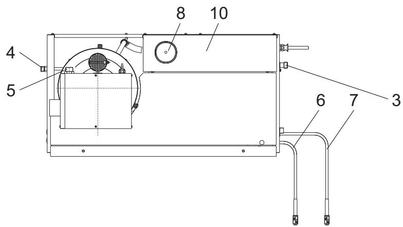
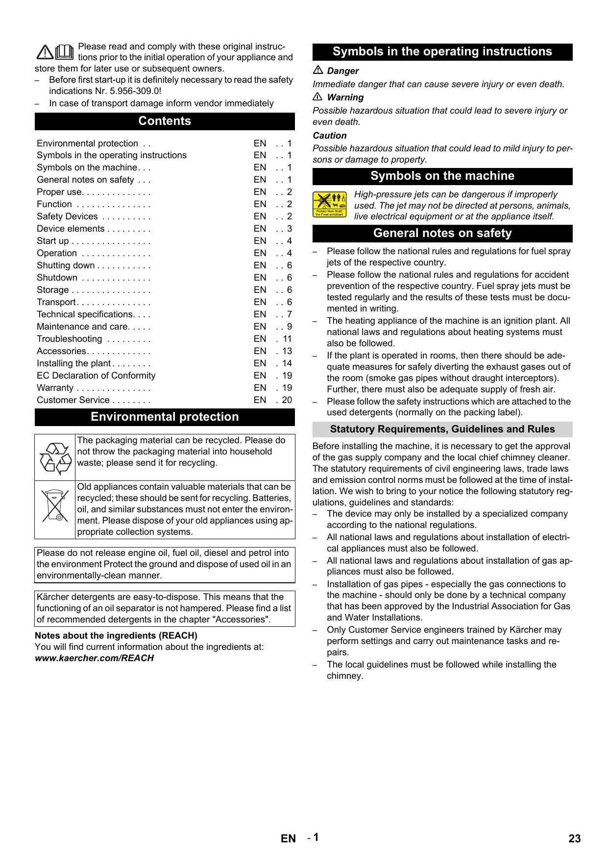
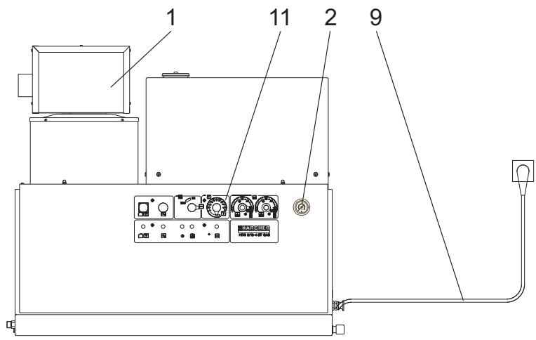
Figure 1
1 Burner
2 Manometer
3 Fresh water inlet with sieve
4 High-pressure outlet
5 Gas connection
6 Detergent suck hose I
7 Detergent suck hose II (optional)
8 Softener container
9 Power supply
10 Float tank
11 Operating field
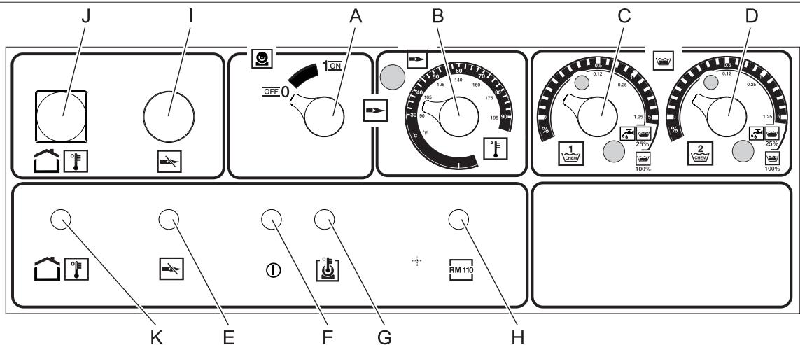
Operating field
Figure 2
A Power switch
B Temperature controller
C Dosage valve I for detergent
D Dosage valve II for detergent (optional)
E Indicator lamp burner failure
F "Ready for use" indicator lamp
G Indicator lamp for engine over-heating
H Indicator lamp for protection against calcification
1 Unlocking key for gas relay
J Unlocking key for exhaust gas thermostat
K Indicator lamp for exhaust gas thermostat
Colour coding
- The operating elements for the cleaning process are yellow.
- The controls for the maintenance and service are light gray.
Start up
Danger
Risk of injury! Device, tubes, high pressure hose and connections must be in faultless condition. Otherwise, the appliance must not be used.
Power connection
- For connection values, see technical data and type plate.
- The electrical connections must be done by an electrician according to IEC 60364-1.
Operation
Safety instructions
The operator must use the appliance correctly. When working with the appliance, he must consider the local conditions and pay due care and attention to other persons, in particular children, who are nearby.
Never leave the appliance unattended when it is in operation.
Danger
Danger of scalding by hot water! Do not direct the water jet on persons or animals.
- Risk of burns on account of hot surfaces! Do not touch uninsulated pipes and hoses when hot water operations are on. Hold the jet pipe only at the handles. Do not touch the exhaust holder of the continuous heater.
- Risk of poisoning or itching on account of detergent! Follow the given instructions for using detergents. Store detergents safely and protect them against access by unauthorised persons.
Danger
Risk to life on account of electric shock! Do not direct the water jet on the following equipment:
- Electrical appliances and plants,
the unit itself, - all electricity-carrying parts in the working area.
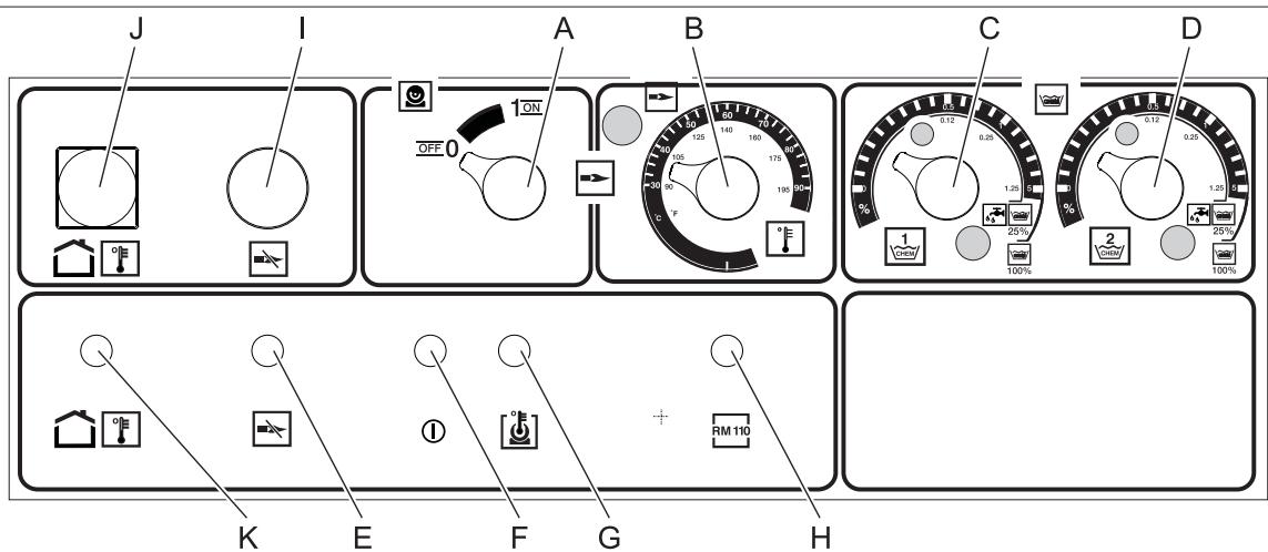
There is a recoil pressure arising from the water jet that comes out from the spray pipe. The angular spray pipe brings about an upward force.
Danger
- Risk of injury! The recoil pressure of the spray pipe can throw you off-balance. You may fall. The spray jet can fly off and cause damage to persons. Search a secure place to stand and hold the gun firmly. Never hold on tightly to the lever of the hand spray gun.
- The jet must not be directed at other persons or directed by the user at him/herself to clean clothing or footwear.
- Risk of injury from parts flying off! Flying-off fragments or objects can injure people or animals. Never direct the water jet on fragile or loose objects.
- Risk of accident on account of damage! Clean tyres and valves from a minimum distance of 30 cm.
Warning
Danger from substances that are harmful to health! Do not spray the following materials as they can swirl up substances that are harmful to health:
Materials containing asbestos,
Materials that could contain substances harmful to health.
Danger
- Risk of injury on account of the emanating water jet that could be hot! Only original Kaercher high pressure hoses are optimally suited for the plant. No guarantee can be given if you use any other hoses.
- Detergents can prove to be a health hazard! If any detergents are added, the water let out of the plant is not of potable quality.
- Risk of hearing impairment while working on noise-making parts! If so, wear ear plugs.
Making the plant ready for operations
Danger
Risk of injury on account of the emanating water jet that could be hot!
Danger
Check the high pressure hose for damage before every use.
Please arrange for the immediate replacement of a damaged high pressure hose.
Check high pressure hose, pipe connections, fittings and water jet for damage every time before use.
Check hose coupling to ensure that it sits firmly and is leak-proof.
Caution
Risk of damage on account of dry running.
Check filling level of the detergent container and refill if required.
Check softener fluid level and refill if necessary.
Switch-off in case of emergency
Turn the appliance switch (A) to "0".
Shut off water supply.
Activate hand spray gun until device is pressure-less.
Close the gas inlet.
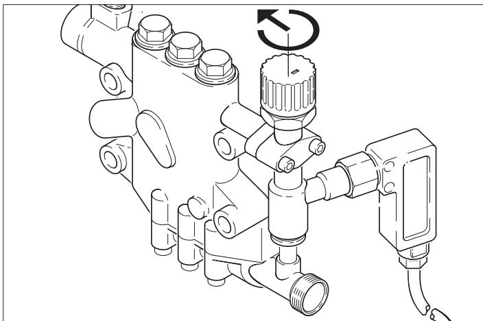
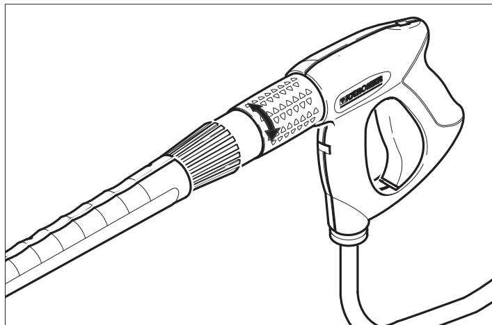
Set working pressure and flow rate
Appliance setting

Turning the quantity regulation valve in clock-wise direction will result in higher working pressure and larger volume.
Turning the quantity regulation valve in an anti-clockwise direction will result in lower workign pressure and smaller quantities.
Settings at the Easy press gun (optional)

Turning the water quantity regulator to the right gives more water flow and higher working pressure.
Turning the water quantity regulator to the left gives lesser water flow and lower working pressure.
Operating with cold water
Open the water supply.

Symbol "Engine on"
Pull the lever of the hand-spray gun and set the appliance switch (A) to "1" (engine on).
The indicator lamp for operational readiness (F) shows that the appliance is in stand-by mode and ready to be operated.
Operating with hot water

Danger
Scalding danger!
Caution
Hot water operations without fuel will cause damage to the fuel pump. Ensure adequate fuel supply before starting hot water operations.
If required, the burner can also be turned on subsequently.

Symbol "Burner on"
Turn the appliance switch (A) to "Burner on".
Set the desired water temperature on the thermostat (B). Maximum temperature is 98^
Operations stand-by
- The appliance will switch off if the lever of the hand-spray gun is released during operations.
The appliance will automatically start again when you open the gun again within the stand-by period (2 ... 8 minutes). - If the stand-by period is exceeded, the safety time mechanism switches off the pump and the burner. The indicator lamp Operations Stand-by (F) goes off.
- To restart the appliance, set the appliance switch to "0" and then switch on the appliance again. If the appliance is operated using remote control, the appliance can be restarted by using the corresponding switch of the remote control device.
Selecting the nozzle
- Vehicle tyres are only cleaned using the flat spray nozzle (25^) from a minimum spraying distance of 30~cm . The round spray should never be used to clean tyres.
The following nozzles can be selected for all other tasks:
| Dirt | Nozzle | Spray an-gle | Part no. 6.415 | Pressure [MPa] | Recoil [N] |
| HDS 9/16 | |||||
| strong | 00060 | 0° | -649 | 16 | 46 |
| medium | 25060 | 25° | -647 | ||
| light | 40060 | 40° | -648 | ||
| HDS 12/14 | |||||
| strong | 00080 | 0° | -150 | 14 | 55 |
| medium | 25080 | 25° | -152 | ||
| light | 40080 | 40° | -153 | ||
Use the following nozzles if the pipe length is more than 20m or for more than 2× 10m high pressure hose NW8:
| Dirt | Nozzle | Spray an-gle | Part no. 6.415 | Pressure [MPa] | Recoil [N] |
| HDS 9/16 | |||||
| strong | 0075 | 0° | -419 | 10 | 37 |
| medium | 2575 | 25° | -421 | ||
| light | 4075 | 40° | -422 | ||
| HDS 12/14 | |||||
| strong | 0010 | 0° | -082 | 10 | 46 |
| medium | 2510 | 25° | -252 | ||
| light | 4010 | 40° | -253 | ||
Detergent dosing
- Detergents simplify the cleaning task. They are sucked in from an external detergent tank.
- The basic model of the appliance is equipped with a dosing valve (C). A second dosing device (dosing valve D) can also be procured as special accessory. It is then possible to use two different detergents.
- The dosing quantity is set at the detergent dosing valves (C or D) at the operating panel. The set value corresponds to the percentage share of the detergent.
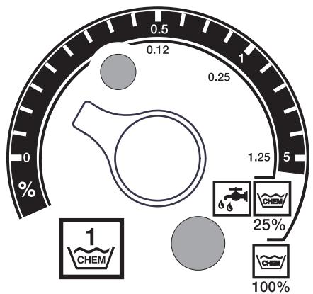
The outer scale is applicable while using undiluted detergents (100% CHEM).
The inner scale is appliance while using 1 + 3 pre-diluted detergents (25% CHEM + 75% water).
The following table gives the detergent consumption for the values on the outer scale:
| Position | 0,5 | 1 | 8 |
| Detergent quantity [l/h] | 14...15 | 22...24 | 50 |
| Detergent concentration [%] | 1,5 | 2,5 | >5 |
The exact dosing depends on:
Viscosity of the deterg
Suction height
- Flow resistance of the high pressure pipe
If an exact dosing is required, then measurehte detergent quantity that is sucked in (for e.g. by sucking in from a measurement beaker).
Note: For list of recommended detergents refer the chapter "Accessories".
Refilling the softener
Caution
There can be calcium deposits in the continuous heater if you use the appliance without softeners.
If the softener tank is empty, the indicator lamp for protection against calcification (H) begins to glow.
Figure 1 - Pos. 8
Refill the softener tank with softener liquid (RM 110 (2.780-001).
Shutting down
Danger
Danger of scalding by hot water. After operation with hot water, the device must be operated with open end handgun with cold water for at least two minutes.
After operation with detergent
If operating with hot water, set the thermostat (B) to the lowest temperature.
Use the appliance for at least 30 seconds without detergent.
Turn off the appliance
Turn the appliance switch (A) to "0".
Shut off water supply.
Activate hand spray gun until device is pressure-less.
Secure the hand spray gun using the safety catch so that it doesn't open accidentally.
Shutdown
If the machine is not to be used for a longer period or if it is not possible to save it in a frost-free environment, then you must take the following measures (see chapter "Maintenance and care"):
Drain water.
Flush device with anti-freeze agent.
Switch off the main switch and secure it or unplug the Cekon plug.
Close the gas inlet.
Storage
Caution
Risk of injury and damage! Note the weight of the appliance in case of storage.
Transport
Caution
Risk of injury and damage! Observe the weight of the appliance when you transport it.
When transporting in vehicles, secure the appliance according to the guidelines from slipping and tipping over.
Technical specifications
| HDS 9/16-4ST Gas | HDS 9/16-4ST Gas LPG | HDS 12/14-4ST Gas | HDS 12/14-4ST Gas LPG | ||
| 1.251-108 | 1.251-109 | 1.251-110 | 1.251-111 | ||
| Performance data | |||||
| Operating pressure of water (using standard nozzle) | MPa (bar) | 16 (160) | 16 (160) | 14 (140) | 14 (140) |
| Max. excess operating pressure (safety valve) | MPa (bar) | 18,5 (185) | 18,5 (185) | 18,5 (185) | 18,5 (185) |
| Water flow (can be regulated in a phase-less manner) | I/h (l/min) | 500-1000 (8,3-16,6) | 500-1000 (8,3-16,6) | 600-1200 (10-20) | 600-1200 (10-20) |
| Suction of detergent (can be regulated in a phaseless manner) | I/h (l/min) | 0-50 (0-0,8) | 0-50 (0-0,8) | 0-60 (0-1) | 0-60 (0-1) |
| Water connection | |||||
| Min. feed volume | I/h (l/min) | 1100 (18,3) | 1100 (18,3) | 1300 (21,7) | 1300 (21,7) |
| Feed pressure (min.) | MPa (bar) | 0,1 (1) | 0,1 (1) | 0,1 (1) | 0,1 (1) |
| Max. feed pressure | MPa (bar) | 0,6 (6) | 0,6 (6) | 0,6 (6) | 0,6 (6) |
| Electrical connection | |||||
| Current type | -- | 3N~ | 3N~ | 3N~ | 3N~ |
| Frequency | Hz | 50 | 50 | 50 | 50 |
| Voltage | V | 380-420 | 380-420 | 380-420 | 380-420 |
| Connected load | kW | 6,4 | 6,4 | 7,5 | 7,5 |
| Electrical protection (slow) | A | 16 | 16 | 20 | 20 |
| Type of protection | -- | IPX5 | IPX5 | IPX5 | IPX5 |
| Protective class | -- | I | I | I | I |
| Maximum allowed net impedance | Ohm | (0,381+j0,238) | (0,381+j0,238) | -- | -- |
| Power supply | mm² | 5 x 2,5 | 5 x 2,5 | 5 x 2,5 | 5 x 2,5 |
| Temperature | |||||
| Max. feed temperature | °C | 30 | 30 | 30 | 30 |
| Max. operating temperature of hot water | °C | 98 | 98 | 98 | 98 |
| Max. temperature safety thermostat | °C | 110 | 110 | 110 | 110 |
| Temperature increase during maximum water flow | °C | 60-65 | 60-65 | 60-65 | 60-65 |
| Gross heating performance | kW | 75 | 75 | 95 | 95 |
| Chimney draught | kPa | 0,01-0,04 | 0,01-0,04 | 0,01-0,04 | 0,01-0,04 |
| Gas connection values | |||||
| Natural gas E (G 20) | m³/h | 7,2 | -- | 9,8 | -- |
| Natural gas LL (G 25) | m³/h | 8,2 | -- | 11,4 | -- |
| Rated connection pressure (natural gas) | kPa | 1,8-5 | -- | 1,8-5 | -- |
| Propane | kg/h | -- | 5,7 | -- | 7,2 |
| Rated connection pressure (Propane) | kPa | -- | 5-6 | -- | 5-6 |
| Environment data | |||||
| Rated utilisation level | % | 97 | 97 | 97 | 97 |
| Standard emission factor NOx(natural gas G 25) | mg/kWh | < 40 | -- | < 40 | -- |
| Standard emission factor CO (natural gas G 25) | mg/kWh | < 40 | -- | < 40 | -- |
| Values for chimney dimensions | |||||
| Suitability for excess pressure (min.) | kPa | 0,05 | 0,05 | 0,05 | 0,05 |
| Draught requirements | kPa | 0 | 0 | 0 | 0 |
| Exhaust flow - full load | kg/h | 130 | 130 | 166 | 166 |
| CO2(Natural gas) | % | 9,5 | -- | 9,5 | -- |
| CO2(Propane) | % | -- | 12 | -- | 12 |
| Exhaust temperature max./min. | °C | 190/150 | 190/150 | 170/130 | 170/130 |
| Combustion air/air supply | Max. length: 10 n with two 90° arches (min. diameter 100 mm) From the installation room or fresh outside air - depending on the local regulations. | ||||
| Condensate drain-out | |||||
| Condensate drain-out (max.) | I/h | 4 (via siphon into the drain- age system) | 4 (via siphon into the drain- age system) | 4 (via siphon into the drain- age system) | 4 (via siphon into the drain- age system) |
| Connectiing piece | DN | 40 (HTR) | 40 (HTR) | 40 (HTR) | 40 (HTR) |
| Minimum water column, siphon | mm | 300 | 300 | 300 | 300 |
| Approval EN 60335-2-79 | |||||
| Approval according to as Appliance Directive (90/396/EEC) | -- | Gastec QALow NOx | Gastec QA | Gastec QALow NOx | Gastec QA |
| Appliance category Europe | -- | I 2E (r), I2ELL, I 2H, I2L, I2 HE | I 3P | I 2E (r), I2ELL, I 2H, I2L, I2 HE | I 3P |
| Appliance type | -- | B23, C33,C43, C53 | B23, C33,C43, C53 | B23, C33,C43, C53 | B23, C33,C43, C53 |
| CE Product Identification Number | -- | PIN 0063 BN3880 | PIN 0063 BN3880 | PIN 0063 BN3880 | PIN 0063 BN3880 |
| Dimensions and weights | |||||
| Length | mm | 1124 | 1124 | 1124 | 1124 |
| Width | mm | 558 | 558 | 558 | 558 |
| Height | mm | 966 | 966 | 1076 | 1076 |
| Typical operating weight | kg | 193,5 | 193,5 | 209 | 209 |
| Values determined as per EN 60355-2-79 | |||||
| Noise emission | |||||
| Sound pressure level \(L_{pA}\) | dB(A) | 74 | 74 | 76 | 76 |
| Uncertainty \(K_{pA}\) | dB(A) | 1 | 1 | 1 | 1 |
| Hand-arm vibration value | |||||
| Hand spray gun | \(m/s^2\) | 2,2 | 2,2 | 2,3 | 2,3 |
| Spray lance | \(m/s^2\) | 1,8 | 1,8 | 2,1 | 2,1 |
| Uncertainty K | \(m/s^2\) | 1,0 | 1,0 | 1,0 | 1,0 |
Specifications sheet
Danger
Risk of injury! The main switch of the vacuum cleaner is to be switched off or the Cekon plug must be unplugged while carrying out any repairs or maintenance jobs.
Maintenance schedule
| Time | Activity | Assembly affected | Performance | of whom |
| daily | Check hand-spray gun | Hand spray gun | Check whether the hand-spray gun closes tightly without any leaks. Check the protection mechanism against accidental switching. Replace defective hand-spray guns. | Operator |
| Check high pressure hoses | Outlets, hoses towards working machine | Check hoses to see if there are damages. Replace defect hoses immediately. Danger of accident! | Operator | |
| Check the connecting line with mains plug | Electrical connection with plug/ socket | Check the connecting line with mains plug for damages. If the power cord is damaged, please arrange immediately for the exchange by an authorized customer service or a skilled electrician. | Operator | |
| weekly or after 40 operating hours | Check oil level | Oil tank at the pump | If the oil is milky, it needs to be replaced. | Operator |
| Check oil level | Oil tank at the pump | Check oil level of the pump. Refill oil if required (Order no. 6.288-016) | Operator | |
| Cleaning the sieve | Sieve in water inlet | See section "Clean sieve". | Operator | |
| monthly or after 200 operating hours | Check pump | High-pressure pump | Check the pump for leaks. If the leakage is more than 3 drops per minute, call Customer Service. | Operator |
| Check for internal deposits | Entire plant | Operate the machine using the spray pipe without the high pressure nozzle. If the operating pressure on the manometer of the machine increases to more than 3 MPa, then the plant needs to be decalcified. The same is applicable when an operating pressure of more than 0.7 - 1 MPa is detected while operating the machine without high pressure pipe (water comes out freely at the high pressure outlet). | Operator trained in de-calcification | |
| Cleaning the sieve | Sieve in the water shortage safeguard | See section "Clean sieve". | Operator | |
| after 500 - 700 operating hours | Replace | Electric igniter, ionisation electrode | Replace electric igniter and/or the ionisation electrode. | Customer Service |
| half-yearly or after 1000 operating hours | Oil change | High-pressure pump | Drain off oil. Fill in 1 new oil (Order no. 6.288-016). Check oil level in the oil tank. | Operator |
| check, clean | Entire plant | Visual inspection of the plant, check high pressure connections to see that they are not leaking, check that the over-flow valves are not leaking, check high pressure hoses, check pressure tanks, remove calcium deposits from the heating coil, clean/ replace ionisation electrodes, adjust burner. | Customer Service | |
| Replace the hose | Hose to exhaust pushbutton switch | Install new hose. | Customer Service | |
| annual | Safety check | Entire plant | Perform a safety inspection as per the applicable national rules and regulations for liquid spray jets of the respective country. | Technical expert |
Maintenance contract
You can enter into a maintenance contract with the concerned Kaercher Sales Office for the machine.
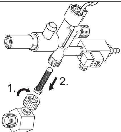
Cleaning the sieve
Sieve in water inlet
Figure 1 - Pos. 3
Shut off water supply.
Remove the water inlet hose on the appliance.
Push out the sieve from the connection using a screw-driver.
Cleaning the sieve
Assemble it back in the reverse sequence.
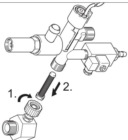
Sieve in the water shortage safe guard
Remove covering panels.
Unscrew the bracket from the safety block.
Turn in screw M8x30 into the sieve.
Pull out the screw and the sieve using pliers.
Cleaning the sieve
Assemble it back in the reverse sequence.
Dscaling
When there are deposits formed in the pipe connections, there is an increase in the flow resistance; this can cause the pressure switch to be triggered.
Danger
Risk of explosion due to combustible gases! Smoking strictly prohibited during decalcification. Ensure proper ventilation.
Danger
Risk of burns injury on account of acid! Wear protective glasses and protective gloves.
Performance
According to statutory requirements, only tested and approve approved boiler decrusting agents may be used.
- RM 100 (Order No. 6.287-008) dissolves chalk and simple compounds of chalk and detergents residues.
- RM 101 (Order No. 6.287-013) dissolves the deposits that cannot be dissolved using RM 100.
Fill a 20 litre container with 15 l water.
Add one litre of boiler decrusting agent.
Connect the water hose directly to the pump and hang in the other free end into the container.
Insert the connected spray pipe without nozzle into the container.
Open the hand-spray gun and do not close it during the decalcification process.
Switch on the appliance switch to "Burner on" until the temperature of approx. 40^ is reached.
Switch off the appliance and let it stand for 20 minutes. The hand-spray gun must remain opened.
Then pump out the machine until empty.
Note: As an anti-corrosion measure and for neutralising the acid residue, we recommend that you finally pump an alkaline solution through the machine (for e.g. RM 81) via the detergent tank.
Frost protection
The machine should be stored in frost-free rooms. In case there is frosting risk, for e.g. if the machine is installed in open areas, then the machine must first be emptied and flushed using an anti-freezing agent.
Drain water
Screw off water supply hose and high pressure hose.
Operate device for max. 1 minute until the pump and conduits are empty.
Screw off supply hose at boiler bottom and drain heating spiral empty.
Flush device with anti-freeze agent
Note: Observe handling instructions of the anti-freeze agent manufacturer.
Fill in normal anti-frost agents in the swimmer tank right until the top.
Place the collection trough under the high pressure exit.
Switch on the appliance and let it run until the safety mechanism against lack of water in swimmer tank gets activated and the machine is switched off.
Fill the boiler floor and siphon with anti-frost agent.
A certain corrosion protection is achieved with this as well.
Troubleshooting
Danger
Risk of injury! The main switch of the vacuum cleaner is to be switched off or the Cekon plug must be unplugged while carrying out any repairs or maintenance jobs.
| Fault | Possible cause | Remedy | of whom |
| Machine is not running; indicator lamp for operations stand-by (F) is not glowing | There is no voltage in the machine. | Check electrical mains. | Electrician |
| Safety time switch is on. | Switch off the appliance switch briefly and switch it on again. | Operator | |
| Fuse in the control circuit (F3) has burnt off. Fuse is located in the control transformer (T2). | Install a new fuse; if it burns out again, then remove the cause for the over-loading. | Customer Service | |
| Pressure switch HP (High pressure) or LP (Low pressure) is defective. | Check pressure switch. | Customer Service | |
| Timer module (A1) defective. | Check connections, replace if required. | Customer Service | |
| + Indicator lamp for engine over-heating (G) is glowing | Thermal sensor (WS) in the engine or the over-current protection switch (F1) has got activated. | Rectify cause for over-loading. | Customer Service |
| The water shortage safeguard in the swimmer tank has got activat-ed. | Remove the water shortage. | Operator | |
| Burner does not ignite or the flame glows off during operation | Thermostat (B) has been set at a very low temperature. | Set the thermostat to a higher level. | Operator |
| Machine switch is not positioned to burner | Switch on the burner. | Operator | |
| The water shortage safeguard in the safety block has got switched off. | Ensure adequate water supply. Check machine for leaks. | Operator | |
| Close the gas valve. | Open gas valve. | Operator | |
| The maximum temperature limiter in the water outlet (> 110 °C) has got triggered. | Let the boiler cool down and restart the appli-ance. | Operator | |
| Check thermostat. | Customer Service | ||
| Indicator lamp for exhaust gas thermostat (K) is glowing | No gas supply. | Open the gas supply. | Operator |
| The incoming supply or exhaust air outlet has got blocked. | Check ventilation and exhaust system. | Operator | |
| Boiler floor is too hot. The maxi-mum temperature limiter in the boiler floor (> 80 °C) has got trig-gered. No condensate water in the boiler. | Add 5 litre water via the measuring nozzle for exhaust gas. | Operator | |
| Automatic gas firing system is showing interruption. | Press the unlocking key for the gas relay (I). | Operator | |
| No ignition. * | Check electrodes distance between gas fir-ing system and ignition cable. Rectify the dis-tance or replace defective parts. Clean it, if necessary. | Customer Service | |
| Blower or speed control plate is defective. * | Check blower and speed control plate. Replace plug and cables. Replace defective parts. | Customer Service |
Note
Press unlocking key for exhaust gas thermostat (J) to unlock the flame monitoring mechanism.
| Fault | Possible cause | Remedy | of whom |
| Indicator lamp for exhaust gas thermostat (K) is glowing | The exhaust temperature limiter has been triggered. | Open the hand-spray gun until the plant has cooled down. Switch the plant off and then on on the operating panel to unlock the temper- ature limiter. If the event recurs, call Custom- er Service. | Operator |
| Indicator lamp for protection against calcification (H) glows | The softener is over. | Refill the softener. | Operator |
| Inadequate or no flow of de- tergent | Dosing valve to position "0". | Adjusting the detergent metering valve. | Operator |
| Detergent filter blocked or tank is empty. | Clean and/or refill. | Operator | |
| Detergent suction hoses, deter- gent metering valve or detergent solenoid valve are leaky or blocked. | Check, clean. | Operator | |
| Electronics or solenoid valve is de- fective. | Replace | Customer Service | |
| Full pressure does not build up in the appliance | Flushed the nozzle. | Replace the nozzle. | Operator |
| Detergent tank is empty. | Refill detergent. | Operator | |
| Not enough water | Ensure adequate water supply. | Operator | |
| Sieve at the water inlet is blocked. | Check, dismantle sieve and clean it. | Operator | |
| Leaky detergent dosing valve. | Check and seal it. | Operator | |
| Leaky detergent hoses. | Replace | Operator | |
| Swimmer valve is jammed. | Check and ensure that it moves freely. | Operator | |
| Safety valve is leaky. | Check the setting; install new washers, if re- quired. | Customer Service | |
| Flow valve is leaky or has been set at a low value. | Check valve parts; replace damaged parts; clean the dirt. | Customer Service | |
| Solenoid valve for pressure re- lease is defective. | Replace solenoid valve. | Customer Service | |
| High pressure pump is knocking; manometer is swaying wildly | Vibration dampener is defective. | Replace vibration dampener. | Customer Service |
| Water pump does not suck in ade- quate air. | Check suction system and remove leaks. | Operator | |
| Device continuously turns on and off while hand spray gun is open | Nozzle in spray pipe is blocked. | Check, clean. | Operator |
| Appliance is decalcified. | See section "Dscaling". | Operator | |
| Switching point of the over-current monitor has got shifted. | Get somebody to reset the over-current monitor. | Customer Service | |
| Sieve blocked in the water short- age safe guard. | Check, dismantle sieve and clean it. | Operator | |
| Appliance does not switch off when the hand-spray gun is closed | The pump has not been fully vent- ed. | Set the machine switch to "0" and pull the hand-spray gun until no fluid comes out of the nozzle. Turn on the appliance again. Repeat this procedure until the full operating pres- sure is reached. | Operator |
| Safety valve or safety valve wash- er is defective. | Replace the safety valve and/or the washer. | Customer Service | |
| Pressure switch of the overflow controller. | Check pressure switch and overflow controller. | Customer Service |
Accessories
Detergent
Detergents simplify the cleaning tasks. The table gives a selection of detergents. Please read the instructions on the packaging carefully before working with any detergents.
| Area of application | Dirt, type of application | Detergent | pH value (approx.) 1 %-solution in tap water |
| Vehicle dealers, fuel stations, freight forwarders, car pools | Dust, street dirt, mineral oils (on painted areas) | RM 55 ASF ** | 8 |
| RM 22/80- Powder ASF | 12/10 | ||
| RM 81 ASF | 9 | ||
| RM 803 ASF | 10 | ||
| RM 806 ASF | 11 | ||
| Vehicle protection | RM 42 Cold wax for high-pressure cleaners | 8 | |
| RM 820-Hot wax ASF | 7 | ||
| RM 821-Wax spray ASF | 6 | ||
| RM 824-Super pearl wax ASF | 7 | ||
| RM 44 Rim cleaning gel | 9 | ||
| Metal-processing industry | Oils, greases, dust and similar impurities and dirt | RM 22- Powder ASF | 12 |
| RM 55 ASF | 8 | ||
| RM 81 ASF | 9 | ||
| RM 803 ASF | 10 | ||
| RM 806 ASF | 12 | ||
| RM 31 ASF (for stronger dirt) | 12 | ||
| RM 39- liquid (with anti-corrosion agents) | 9 | ||
| Food-processing units | Light to heavy dirt, greases/ oils, large areas | RM 55 ASF | 8 |
| RM 81 ASF | 9 | ||
| RM 882 Gel foam OSC | 12 | ||
| RM 58 ASF (Foam detergent) | 9 | ||
| RM 31 ASF * | 12 | ||
| smoke resin | RM 33 * | 13 | |
| Cleaning and disinfection | RM 732 | 9 | |
| Disinfection | RM 735 | 7...8 | |
| Chalk, mineral deposits | RM 25 ASF * | 2 | |
| RM 59 ASF (Foam cleaning) | 2 | ||
| Sanitary area *** | Chalk, stone, soaps, etc. | RM 25 ASF * (basic cleaning) | 2 |
| RM 59 ASF (Foam cleaning) | 2 | ||
| RM 68 ASF | 5 |
- = only for short use, two-step method, rinse with clean water
** = ASF = easy-to-dispose
*** = Foam-Star 2000 is best suited for initial spraying
Installing the plant

Only for authorised technicians!
General
- The heating appliance of the machine is an ignition plant.
Please follow the local regulations while installing it.
Use only certified chimneys/exhaust pipes.
General rules for gas
- The installation of gas pipes as well as the gas-side connections of the appliance should only be done by a company specialised in gas and water installations.
- Settings and repairs to the gas burner should only be carried out by trained Kärcher Customer Service Technicians.
Gas pipes
- There should be a manometer and a locking valve in the gas pipe that should have a minimum diameter of 1 inch.
- Due to the vibrations caused by the high pressure pump, the rigid gas pipe must be connected to the appliance using a flexible gas hose.
- For gas pipes that are more than 10m in length, the diameter must be 1 1/2 inch or more. The gas connection to the appliance has a diameter of 1 inch.
Danger
While attaching the flexible gas hose to the burner, the connection nipple must be held with a fork key SW 36. The connection nipple should not get twisted vis-a-vis the burner casing. The threaded connection should only be sealed using a sealant approved by DVGW. After connection, check the joint using a DVGW leak-search spray to ensure that the joint is leakproof. The width of the gas pipe must be calculated according to DVGW TRGI 1986 or TRF 1996. The diameter of the gas connection to the appliance does not automatically become the diameter of the pipe connection. The dimensioning and installation of the gas pipes must be done according to the corresponding norms and regulations.
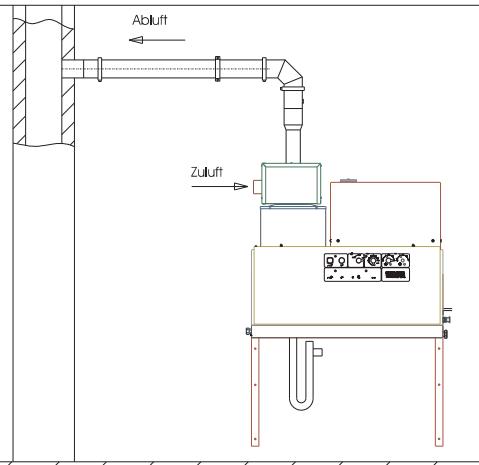
Ventilation / exhaust system
Each appliance must be connected to a separate chimney.
- The exhaust system must be designed according to the local rules and regulations after consulting the concerned chimney expert.
Gas appliances with an exhaust system that sucks out the combustion air from the installation room
Type B23
Gas appliances without flow controller where all parts of the exhaust system that are subjected to excess pressure are free of combustion air. The B23 installation opens new options of connecting the appliance to a traditional single-draught chimney according to DIN 18160 and operating it depending on the air conditions in the room. The only requirement is that the chimney must be suitable for being connected to combustion devices (i.e. it has been cleaned by inserting a stainless steel pipe).
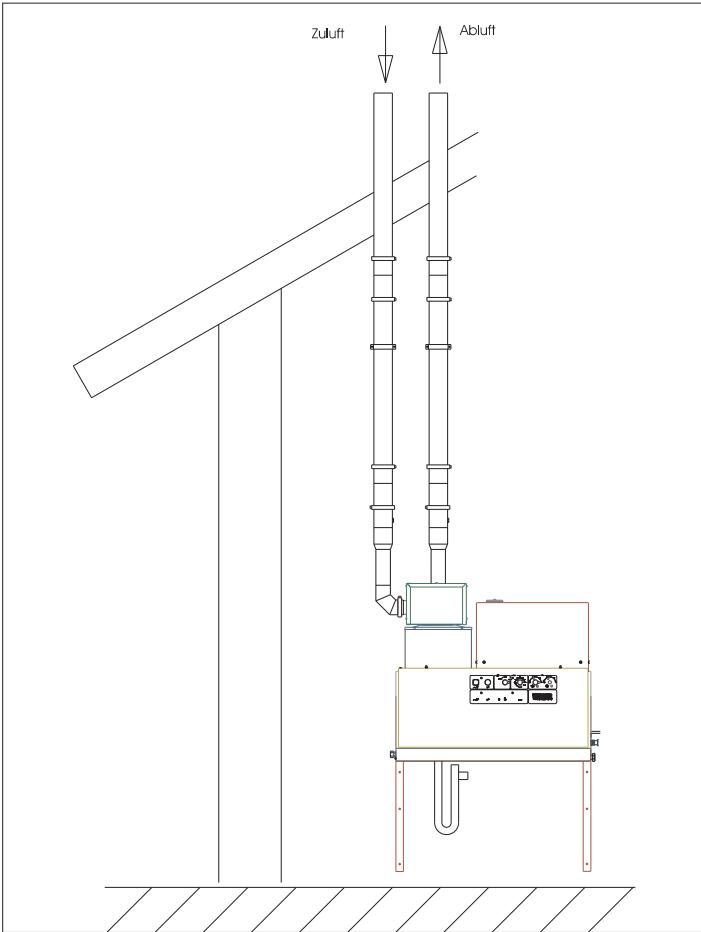
Gas appliance with an exhaust system that removes the combustion air into the open via a closed system
Type C33
Gas appliance with combustion air supply and exhaust system placed vertically over the roof. The inlets are located almost close to each other in the same pressure range.
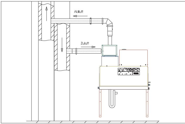
Type C43
Gas appliance with combustion air inlet and exhaust system to be connected to an exhaust system.
Type C53
Gas appliance with separate combustion air inlet and exhaust system. The inlets are located in different pressure ranges.
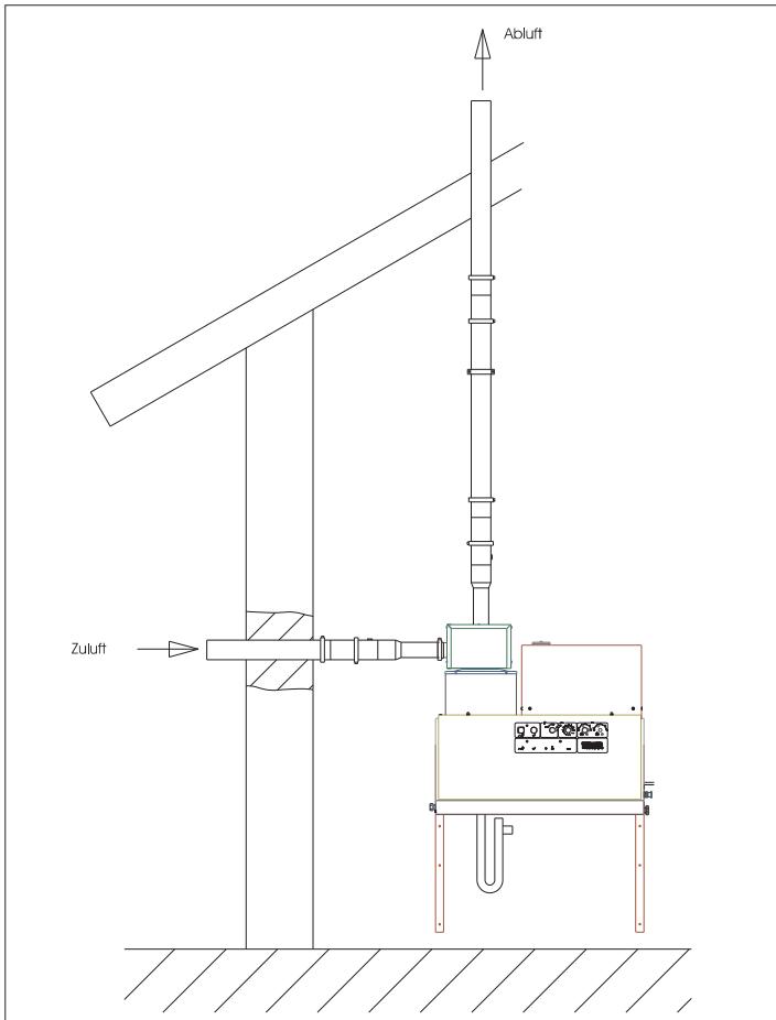
Note: The chimney draught specifications given in the technical data must be maintained if you want to achieve the prescribed combustion values.
Drainage of condensate
The condensate pipes must be siphoned directly at the condensate connection. The siphon height must be 30~cm . The siphon is included in the scope of delivery. The condensate pipe must not be firmly connected to the drainage system. The condensate must first flow out freely into a funnel or a neutralisation container.
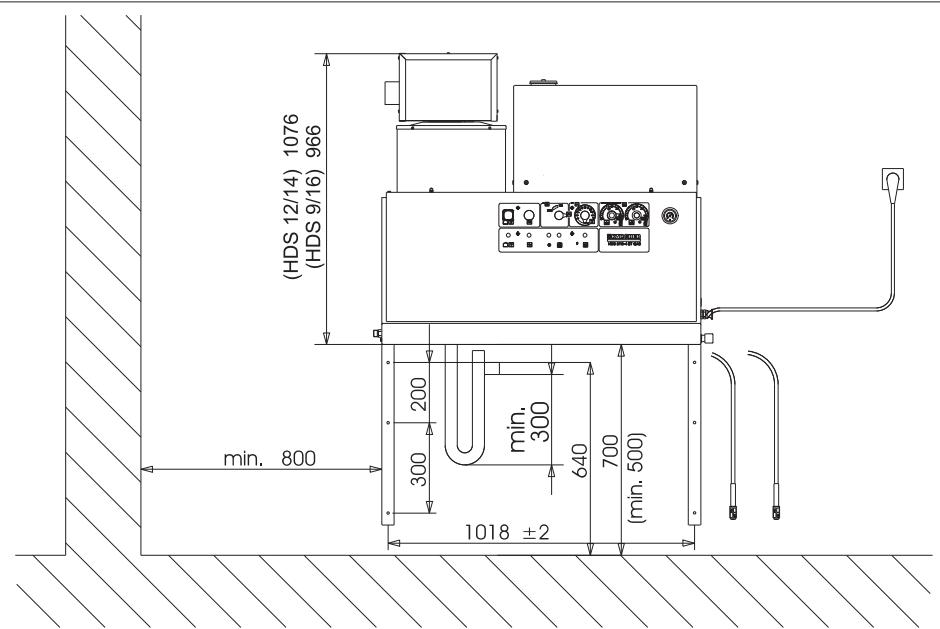
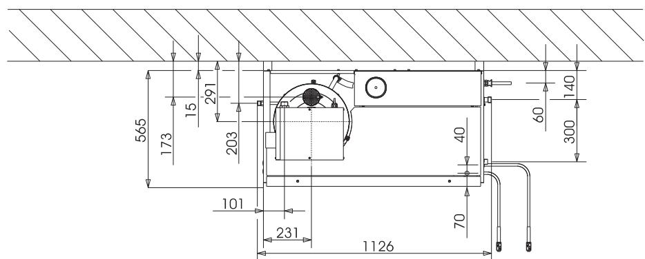
Wall mount
- Before installing, please check the load-bearing capacity of the wall. The fastening material delivered with the plant is suitable for concrete walls. Use suitable anchor plugs and screws for hollow component walls, brick walls and gas concrete walls - for e.g. injection anchor (for drilling diagram see the specifications sheet).
Figure 3 - items 19 and 25
The appliance should not be directly attached to the network of water and high pressure pipes. It is mandatory to install the connecting hoses.
Figure 3 - A
A shut-off tap must be installed between the main water supply and the connecting hose.
Installing the high pressure connections
All national laws and regulations about installation of electrical appliances must also be followed when installing high pressure lines.
- The pressure loss in the pipe connections must lie below 1.5MPa .
- The completed pipe connections must be checked using 32 MPa.
- The insulation of the pipes must be resistant to temperatures until 100^ .
Install the detergent tank
Figure 3 - Pos. 20
The tanks are to be installed in such a way that the lower level mirror of the detergent should not be more than 1.5m under the machine floor and the upper level mirror should not be located above the machine floor.
Water supply
Figure 3 - B and item 19
The water inlet is to be connected to the main water supply using an appropriate water hose.
- The water supply must have a minimum output of 1300 ~l/h at minimum 0.1 MPa.
- The water temperature must lie below 30^ .
Electrical connection
Caution
The highest allowed net impedance at the electrical connection point (refer to technical data) is not to be exceeded. In case of confusion regarding the power impedance present on your connection, please contact your utilities provider.
Note: Operating procedures create short term power sinkings. During unfavorable net conditions other devices might be disturbed.
- For connection values, see technical data and type plate.
- The electrical connections must be done by an electrician according to IEC 60364-1.
- Current-carrying parts, cables and appliances in the working area must be installed in a defectless state and must be protected against water sprays.
To avoid accidents due to electrical faults we recommend the use of sockets with a line-side current-limiting circuit breaker (max. 30 mA nominal tripping current).
Firmly installed electrical connection
Establish the electrical connection.
A main switch that can be locked (figure 3 - item 6) is to be installed at a safe and easily accessible place to switch off the stationary high pressure cleaner.
The contact opening of the main switch must be minimum 3 mm.
Electrical connection with plug/ socket
Install Cekon plug on the connection cable of the appliance.
Insert Cekon plug into the socket.
To switch off the stationary high pressure cleaner, the Cekon plug must be easily accessible so that it can be removed from the mains.
Initial startup
The device is set in the factory as a natural gas device to gas type G 20 and as LPG device to G 31. While switching over natural gas devices to G 25 or other natural gases (see type plate) or the LPG device to G 30 or other LPGs (see type plate), the natural gas exhaust values in case of natural gas devices and the LPG exhaust values in case of LPG devices are to be set according to the service information.
The enclosed empty type plate will be filled up with values of the new gas type that is set and will be fixed on the right side of the device in the address field. At the same time, the plate with the G 20 (natural gas device) details or G 31 (LPG device) details fitted at the factory must be removed.
Check gas connection.
Caution
Risk of damage to the appliance on account of over-heating.
Connect the siphon to the boiler floor and fill water.
Fill the boiler via the chimney opening with 4 litres of water.
Before using for the first time, cut off the tip of the lid of the oil tank on the water pump.
Measures to be taken before start-up
Figure 3 - Pos. 14
Connect the high pressure hose with the hand-spray gun and the spray pipe and connect it to the high pressure outlet of the appliance or the high pressure pipe network.
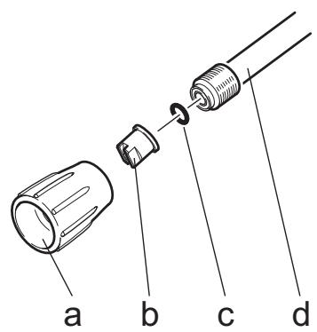
Fasten the nozzle mouth-piece (b) with the union nut (a) on the spray pipe (d). Please ensure that the sealing ring (c) is cleanly positioned in the nut.
Anti-calcification measures
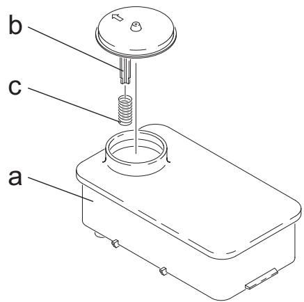
Remove spring (c) from the lid support (b) of the softener tank (a).
Fill the tank with Kaercher softener liquid RM 110 (Order no. 2.780-001).
Danger
Risk of electrical voltage! Setting may only be done by an electrician.
Determining the hardness of tap water:
through the public water supply works,
using a hardness tester (order no. 6.768-004)
Remove the appliance cover.
Open the switch box at the operating panel.
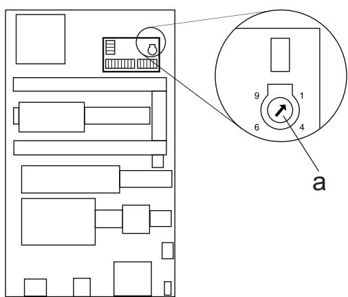
Set the speed potentiometer (a) according to the water hardness. You can refer to the correct setting in the table.
Example:
For a water hardness of 15^ , set 6 on the value scale of the speed potentiometer. This results in a pause of 31 seconds, i.e. the solenoid valve will open briefly every 31 seconds.
| Water hardness (°dH) | 5 | 10 | 15 | 20 | 25 |
| Scale on the speed potentiometer | 8 | 7 | 6 | 5 | 4,5 |
| Pause (in seconds) | 50 | 40 | 31 | 22 | 16 |
Adjusting the operations stand-by time
The operations stand-by time is set on the larger plate on the left side-wall of the electrical cabinet.
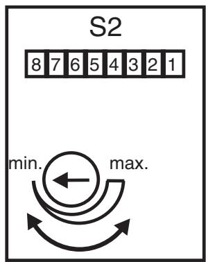
The operations stand-by time is set in the factory to a minimum time of 2 minutes and can be increased to a maximum time of 8 minutes.
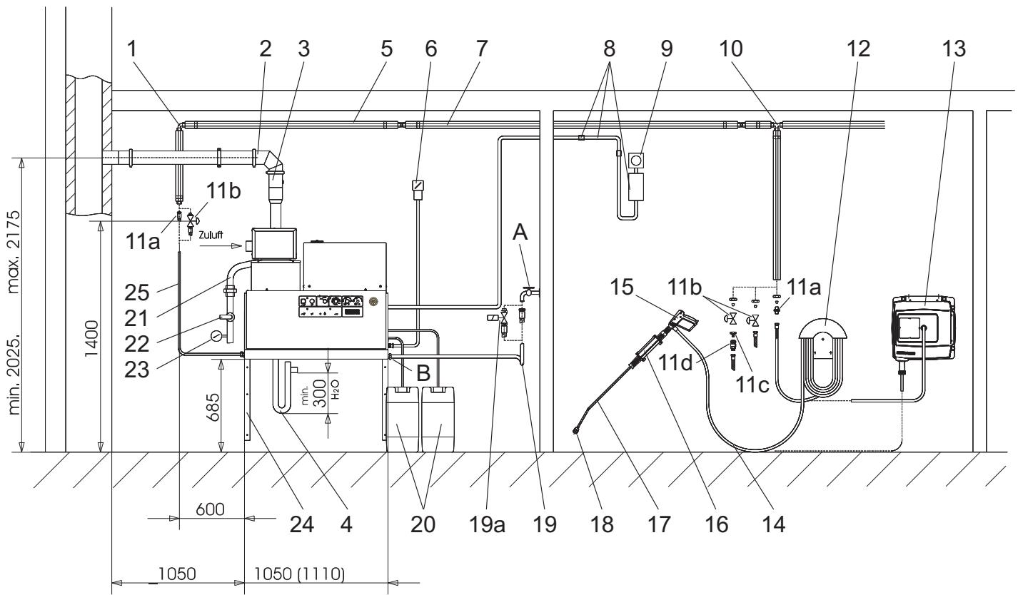
Figure 3
| Item: | Installation material | Order No. |
| 1 | Threaded elbow joint | 6.386-356 |
| 2 | Set of connecting parts, exhaust | 2.640-425 |
| 3 | Set of boiler connecting parts, exhaust | 2.640-424 |
| 4 | Set of siphon parts | 2.640-422 |
| 5 | Thermal insulation | 6.286-114 |
| 6 | Main switch | 6.631-455 |
| 7 | Set of pipes, galvanised steel | 2.420-004 |
| Set of pipes, stainless steel | 2.420-006 | |
| 8 | Remote control set | 2.744-008 |
| 9 | Set of parts for emergency-stop switch | 2.744-002 |
| 10 | T-screws | 6.386-269 |
| 11a | Connection neck, brass | 2.638-180 |
| Connection neck, stainless steel | 2.638-181 | |
| 11b | Shut-off valve NW 8, galvanised steel | 4.580-144 |
| Shut-off valve NW 8, stainless steel | 4.580-163 | |
| 11c | Fixed part for quick coupling | 6.463-025 |
| 11d | Loose part for quick coupling | 6.463-023 |
| Item: | Installation material | Order No. |
| 12 | Hose switch | 2.042-001 |
| 13 | Hose drum | 2.637-238 |
| 14 | High pressure hose 10 m | 6.388-083 |
| 15 | Hand-spray gun Easy Press | 4.775-463 |
| Speed regulator HPS 9/16-4 | 4.775-470 | |
| Speed regulator HDS 12/14-4 | 4.775-471 | |
| 16 | Spray pipe holder | 2.042-002 |
| 17 | Spray lance | 4.760-550 |
| 18 | Nozzle mouth-piece HPS 9/16-4 | 2.883-402 |
| Nozzle mouth-piece HDS 12/14-4 | 2.883-406 | |
| 19 | Water pipes | 4.440-282 |
| 19a | Solenoid valve for water inlet | 4.743-011 |
| 20 | Detergent tank, 60 l | 5.070-078 |
| 21 | Gas hose R1" | 6.388-228 |
| 22 | Gas shut-off valve R1" | 6.412-389 |
| 23 | Manometer, gas (Note! provide shut-off valve in the building.) | 6.412-059 |
| 24 | Set of parts for wall console | 2.053-005 |
| Set of parts for floor frame | 2.210-008 | |
| 25 | High pressure hose | 6.389-028 |
EC Declaration of Conformity
We hereby declare that the machine described below complies with the relevant basic safety and health requirements of the EU Directives, both in its basic design and construction as well as in the version put into circulation by us. This declaration shall cease to be valid if the machine is modified without our prior approval.
Product: High pressure cleaner
Type: 1.251-xxx
Relevant EU Directives
2009/142/EC
2006/42/EC (+2009/127/EC)
2004/108/EC
Applied harmonized standards
EN 55014-1: 2006+A1: 2009+A2: 2011
EN 55014-2: 1997+A1: 2001+A2: 2008
EN 60335-1
EN 60335-2-79
EN 62233: 2008
EN 61000-3-2: 2006+A1: 2009+A2: 2009
HDS 12/14:
EN 61000-3-3:2008
HDS 9/16:
EN 61000-3-11:2000
Applied specifications:
QA 195 (not LPG)
Name of the appointed agency:
for 2009/142/EC
GASTEC
Wilmersdorf 50
7327 AC Apeldoorn
ID No. 0063
5.957-648
The undersigned act on behalf and under the power of attorney of the company management.


Authorised Documentation Representative
S. Reiser
71364 Winnenden (Germany)
Phone: +49 7195 14-0
Fax: +49 7195 14-2212
Winnenden, 2010/12/01
Warranty
The warranty terms published by our competent sales company are applicable in each country. We will repair potential failures of the appliance within the warranty period free of charge, provided that such failure is caused by faulty material or defects in fabrication.
Customer Service
| Plant type: | Manufact. no.: | Start-up on: |
| Testing done on:Findings: | Signature | |
| Testing done on:Findings: | Signature | |
| Testing done on:Findings: | Signature | |
| Testing done on:Findings: | Signature | |
| Testing done on:Findings: | Signature | |
www.kaercher.com/REACH
2006/42/CE (+2009/127/CE)
2004/108/CE

S. Reiser
Head of Appropriation
Responsible de la documentation:
S. Reiser
71364 Winnenden (Germany)
Telephone: +49 7195 14-0
Winnenden, 2010/12/01
Garantie
2006/42/CE (+2009/127/CE)
2004/108/CE
71364 Winnenden (Germany)
Tel.: +49 7195 14-0
Fax: +49 7195 14-2212
Winnenden, 2010/12/01
Garanzia
www.kaercher.com/REACH
Zeef in watertoevoer

S. Reiser
Head of Approbation
71364 Winnenden (Germany)
Tel.: +49 7195 14-0
Fax: +49 7195 14-2212
Winnenden, 2010/12/01
Garantie
www.kaercher.com/REACH
2006/42/CE (+2009/127/CE)
2004/108/CE
71364 Winnenden (Germany)
Tele.: +49 7195 14-0
Fax: +49 7195 14-2212
Winnenden, 2010/12/01
Garantía
www.kaercher.com/REACH
2006/42/CE (+2009/127/CE)
2004/108/CE
71364 Winnenden (Germany)
Tel.: +49 7195 14-0
Fax: +49 7195 14-2212
Winnenden, 2010/12/01
Garantia
Symbol "Motor taend"
Symbol "Braender taend"
2006/42/EF (+2009/127/EF)
2004/108/EF
71364 Winnenden (Germany)
TIf.: +49 7195 14-0
Fax: +49 7195 14-2212
Winnenden, 2010/12/01
Garanti
Relevant EU-directiver
2009/142/EF
2006/42/EF (+2009/127/EF)
2004/108/EF
71364 Winnenden (Germany)
TIf: +49 7195 14-0
Winnenden, 2010/12/01
Garanti
www.kaercher.com/REACH
Symboler i bruksanvisingen
Fara
71364 Winnenden (Germany)
Tel.: +49 7195 14-0
Fax: +49 7195 14-2212
Winnenden, 2010/12/01
Garanti
www.kaercher.com/REACH
71364 Winnenden (Germany)
Puh.: +49 7195 14-0
Winnenden, 2010/12/01
Takuu
www.kaercher.com/REACH

S. Reiser
Head of Appropriation
YTeuHoVos Teknpiwons:
S. Reiser
71364 Winnenden (Germany)
Tnλ::+49719514-0
Φαξ: +49 7195 14-2212
Winnenden, 2010/12/01
Eyyúnon
www.kaercher.com/REACH
Kullanim kilavuzundaki semboller

Tehlike
71364 Winnenden (Germany)
Tel.: +49 7195 14-0
Winnenden, 2010/12/01
Garanti
HnctpyKunno npnmeHeHIO KOMnOHeHTOB (REACH)
AktyaJIbHbIe CBeDEHnO KOMNoHEHTax PpNBeDeHbI Ha Be6-y3Ne no CJeDyUoSeMy aDpecy:
www.kaercher.com/REACH
CnMBOJIbI B pyKOBoDCTBe NO 3KcNJIyaTaUIN
Onachocmb
ДяненocpecmeHNO ap03aue onachocmu, komopar npu-odum K mjaekJIbIM yeeyam unu K cmepu.
IpeynpexdeHue
Дя возможноnomenuаьноonaCHOcmyaquu,komopая можем npueecmu K mxejblm yeeybaM unu K cmepmu.
BhumaHue!
ДявозможиnomeнцuaьноonaCHOcmyaquu,komopая можем npueecmuКпeakummpaamMmUuNoBnebyMamepu-aIbHbIyuep6.
CnmbolbHa npnbope

Haxodyaacra nod ebicokum daaenehuem cmpy ooblo Moxem npu HnnpabunbHom uCnoNb3oBaHuu npedcmaaamb onachocmb. 3anpeaaemc HnnpaBamcbmpyo 60bl Ha IIOdei, KUOBmblx, EKnIueHHOe 3neKmpuececko obopyoaeHue UNu Ha cam ebicOKoHaonopbHou MOOuui annapam.
CpeIcTBA INHdNbUdyaJIbHOJ 3aunTbI

3aunthbie npncocO6nHn CnykaT nna 3auNTbI NOB3OBaTeJI I He DOnKHBb BbIOHTbcra n3 CTPOr NII paBOTaTb B O6XoD CBOx cyHKnI.
Систema пе dioхpenя OT OTCyTCTBn BODbl, 6ak cNONJIaBkOM
CnCTema npedeoxpahEnra OTOCTBnBa BObl npeDToBpaUaET BKJIOueHne HAcoca BbICOKO rAbJeHn pIn HeIOCTaTKe BObl.
CnCTema npeDoxpaHEnna OT OTCyTCTBnBa BOdbI, npeDoxpaHnteJbHbI 6JOK
CnCTema npedoxpaheneo OT OTCyTCTBn BObl npenrTCTBye TnepepeBy ropeIKN npn HeIOCTaTKe BObl. FopeIka 3anyckaetcra TOnbKO pnpnoaue DOCTaTOHORO KOINHeCTBa BObl.
MaHOMeTpnueckn BbIKIIOuTaTeJIb
MaHometpnueckn BbIKIIOUaTeNb BbIKIIOUaET npi6Op npi npBeBbIeHN pa6OeRo daBJeHry. HeJIb3r n3MeHraTb yCTaHOBky.
PpeoXpaHnteIbHbI KJIanaH
При сбоe MaHOMeTpUWeCKOrO BbIKJIuOaTeJЯ OTKpbIbAeTcЯпдoxpaHnteJIbHbI KlnanH.3ToT KlnanH OtperyIpObaH n 3aIIpM6bpObaH ha 3aBoDe-и3rOToBHTeNe. HeIb3Я n3MeHЯТь yCTaHObKy.
KoHTpOJIb pJIaMeHn
При Нedingостк Te TOnnBa Илп NOLOmKe rOpeIkn CnCTeMa KOHTpOJЯ Пламен OTKJIIOUaEт rOpeIky. 3aropaetc KoHTpoJbHajЯ lamma HeuCnpaBnOctn rOpeIkn (E).
3aunta oT neperpy3ok
Ecnn DBrnateIb ropeIkn 3a6JIOKnpoBaH, To BblKnIOUaTeIb yctpoIcTba 3aunTbI OT neperpy3OK BblKnIOueH. DBrnateIb HacoCa BbICOKO rDaBJIeHn3aunIeH BblKnIOuAteJIem 3aunTbI DBrnateJIr n 3aunTHbIM peJe ObMOTkn.
TepMoCTaT Otpa6OtaHHbIX ra3OB
Tepmoctat OTPa60TaHHbIX ra3OB cpa6aTbIbAeT, ecn TEmnepa-tya OTPa60TaHHbIX ra3OB npEbIwaet 320 C.3aropaetc KOnTpOlbHna JAmNoUka tepMoCTata OTPa60TaHHbIX ra3OB (K)
OrpaHnUHTeIb Tempepatypbl
CpaBaIbAeT OpraHnUHTeJIb MaKcImMaJIbHOJ TeMnepaTypbHa IHe KOTJa (>80C) n BOIOBbIpycka (>110C) n 3aropaetc KaOHTpOBHaa JAmNoUka HeNCnPpABHocTn RopeJIKN (E).
IpekeJIOUaTeJIb daBJeHnIg OΓ
IpeeknioateIb daBleHna OΓ oTKIOaet ropeNky,ecn B cnCTeme OTPa6oTaHHoro ra3a BO3HKnIO ype3MepHO BbICOKOE npOTNbOdaBLeHne,HanpIMep,pi3acope.
C6poc daBneHnB CnCTeMe BbICOKO daBHeHn
Iocne otKlnoueHn npBopa c nOmoBIO pyHOro nIcToJIeTaPacnbJInTeJIy I NO nCTeUeHN BpeMeHN NIOrTOBKN KpaBoTeOTKpbIBaETC MaHHTbI KNaHaH, paCNOJIOXKeHHbI B CnCTeMe BbICOKO r DaBHeHn, B pe3yNbTaTe Yero daBHeHne naDaet.

Puc. 1
1 ropelky,
2 MaHometp
3 IINHnI NOaHn CBExeRo BO3dyxA C CeTuaBIM HnIbTpOM
4 BbIXoD BBcOKoro DaBneHn
5 Ra3oBOe noDCoeHHeHne
6 BcabsBaIoun mIaHr dIy MOUeero cpeDCTBa I.
7 Bcabsibaunm uanr nmao o cpectba II (DonolnTeIbHoe o6opydoBaHne)
8 BaK CmryTeJr
9 Iobdo3neKtpnueCTBa
10Пллавковая камера
11 PanaJIb ynpaBneHn
Panaelb ynpablenna
Puc. 2
A BkliouateIb annapata
B PerynlaTOp tempepaTpybl
C Do3npyuocnn KJanaan MOUoceero cpeCTBa I
D Ioznpyuocnn Knaan MOnoUcero cpeICTBa II (OonnoHntJIb-Hoe o6opuydoBAHne)
E KontrpoIbHaJ lamma HeNCpRaBHOCTn ropeJIKN
F KoHTpOJIbHaJ IaMna roTOBHOCTN K 3KcPJIyatauIN
G KoHTpOlbHna JAmna neperpeBa DBrIaTeJIa
H KOHTPOJIbHaJ lamna 3aIITbI OT HAKINII
I Khonka pa36loKIpOBkn ra3oBoro pene
J Khonka pa36nKnpOBKn TepMOCTaTa Otpa60taHHbIX ra3OB
K KoHTpOJIbHaJ lamMa TePmoCTaTa Otpa60TaHHbIX ra3OB
LBeTHa MapKnUpOBka
- Opraны ураловся за поцесca очирten кжелтоюцета.
- OprahbI ynpaBneHnIy IJIyTexHnueckOrO obcnyKnBaHnI cepBnca CBETNo-ceporo Cbeta.
Hauano pa6oTbI
Onachocmb
Onachocmb nonyuhenma pmaem! Pnpobop, noedoayue wnaheu, uhae bicokoo daaehnue u coedunenue dojkhbl haxodumbc8 63ynpehom cocmoHuu. Ecnu ccomohue npubopa He 63ynpeHno, mo npubop uonb30abm HnB3.
ToUHOCTb yCTaHOBKn Do3npyeMOro KoJIuYeCTBa 3aBcNt OT:
BRA3KOCTNMOUeeroCpeDCTBa
- Bbicota BCoca
- rIiPabJIuYeCKOrO cOpOTnBHeHnAaHaRa BbICOKOro daBJeHNJ.
BbIbOuN3 3KcnpJyataun
Onachocmb
Onachocmb obeapuebanu aopye bodo! Pocne 3knpnyama-uu c oopye bdoo npubop dno oxnajdehura cledyem e meuen He meene deyx Muhym 3knpnyamupoeambc xolodho bdoou c omkpblbim nucmonemom.
Pocne 3Kcnpnyataun C MOUUM CpeDCTBOM
B pexnme ropey B0dbI yctaHOBITb peryIaTOp tempeatypb1 (B) Ha camyU Hn3kyU Tempepatypy.
→ДаТь пибору поработаь в тeyене 30 cekyнд 6e3 моюшero срсдтва.
Bbikloue Hne annapata
→ BbIKIIOuHaTeJI npI6Opa (A) noBepHyT b nOLOKeHne ,0".
→ 3aKpbTb noJaCy BOJbl.
HauKaTb pbUar nIcToIeta-pacnbIInTeJIa, noka annapaT He OCBo6OuNTcR O T daBJeHn.
3a6nokpoBaT nIcToJIeT-pacblntelb c nOmoUbOppeoXpaHNTeBHorO fNKcaTopopAOT CnyaHOrO Haxatna.
BbIbO n3 3KcπJyatauHn
PnI dIInTeJIbHbIX npepeBbax B pa6Ote IIN Ipn HeBO3MOXHOCTN XpaHeHnI npIbopa B MeCTax, 3aunIeHHbIX OT MOpO3a, IPOBeCTN CneDyUoIe MeponpIyrTn (CM. rnaBy «TexHnueckoe ObcIyJxHBAHne u yXoD», pa3dE«3aunTa ot MOpO3OB»).
→ CnITb BODy.
→PpOMbIBKa npn6opa aHTnΦpnsOm.
→ BbIKHIOHTb 3a6JIOKIPOBaTb IJIaBHBi BBIKIIOUaTeJIb INIOTCOEINHHTb WTEKePbI pa3bem Cekon.
→ 3aKpbIb IpoJaCy r3a.
XpaHeHne
BhumaHue!
Onachocmb nolyeHn mpaam u nopekdeHu! Ppu xpaheHuu cnedyem obpamumb bHumaHue Ha eec ycmpoucm8a.
TpaHcnpToBka
BHUMAHue!
Onachocmb nolyeHnmpaM u nopekdeHn! Ipu mpanCnpmupoeke cneodyem obpammb bHumaHue ha bec ycmpo-cmea.
→Пи пеевозк annapapaВ TраHCNOpTbIx CpeДCTbax Cne-ДуET yuNTbIBaTb DeIeSTbYIOJIne MeCThBIE rOcUdApCTBeHbIe HOpMbI, HanpabJIeHHbIe Ha 3aIHTy OT cKoJIbXeHnI n OnpOKn-DbIBaHnI.
3aunta ot 3amep3aHnA
Pn6bOp DoJxeh 6bItb ycTaHOBJeH BV NOMEuEHN, 3aunuEHHom OT MOpO3OB. Pn ONaCHOCTN 3aMeP3aHnI, HApnIMep, Pn MOtAxe Ha OTKpbITOM BO3dyXe, Pn6bOp HxJHo ONOPOXHITb IN PpOMbITb aHTnΦpn3OM.
CnB BoDbl
OTBnHTnte IJIaHr IOpaun BOdbI IN JIaHr BbICOKO rAbJIe-HNIA.
OCTaBbTe npi6op BkIIOHeHHbIM B TeueHm He 6oJee 1 MInHyt b Do Tex nop, noka Hacoc N Tpy6oNpOBoDbl He OnopoXHrTcR.
OTCoeDINHTb NOdaHouzni npoBOiD,OTBepHyB erO OTnHa KOTJa nOCBO6OuHBaTeJIbHbI 3MeeBVK.
PpnoJlackaTb annapaT aHTnФиprn3OM
Yka3aHne: Co6IIOdaIe INHCTpyKcIMn IO NCIOJIb3OBAHIO aHTN-ФрИЗ.
B6aK c nonJaBkOM 3aJIITb DoBepxy o6bIuHbI aHTnΦpI3.
YCTaHOBNTb IOJ BbIXOOM BblCOKOrO daBJIeHnI POxOJaUyEO MKOCTb.
→ Bкнючпь пибор и дать Emу поаботаь до tex nop, пoka He сработаet систema пpeдoxpaHEHЯ OT HeIoCTaTKa BOdby 6aka c nonnaBkOMи пибор He BBkIJOuHTcR.
→ 3aNoJIHnTbДHO KOTlaи cNΦOH aHTnΦpU3OM.
B pe3yIbTaTe 3TOrO TaKKe DoCTnIraEtc onpeJeJIeHHa aHTNKoP03uOHHa 3aUHTa.
ПомоцьВслуcaeноладok
Onachocmb
Onachocmb nojyuhenma paaM! Npeod npoeedeHuem pemoHmhbix paobom u paobom no mexnueckomy obcnykueaHIO cne- dyem bIKIQUumb aanaBHy bIKNQUameJIu uno omcoedunmb wmekepbni pa3bem Cekon.
YctaHOBka 6aKOB cMOIOUcM CpeDCTBOM
Pnc.3-103.20
MeponpnyTna Do BbOda B 3KcNpyatauH
Pnc.3-103.14
PpOdyKT BbICOKHOAnOpHbI MOUcIe
npu6op
Tun: 1.251-xxx
OCHOBHbIe DnpeKTHBbI EC
2009/142/EC
2006/42/EC (+2009/127/EC)
2004/108/EC
PpIMeHeHHbIe rapMOHn3InpOBaHHbIe
HOpMbI
EN 55014-1: 2006+A1: 2009+A2: 2011
EN 55014-2: 1997+A1: 2001+A2: 2008
EN 60335-1
EN 60335-2-79
EN 62233: 2008
EN 61000-3-2: 2006+A1: 2009+A2: 2009
HDS 12/14:
EN 61000-3-3:2008
HDS 9/16:
EN 61000-3-11:2000
PpimHeHHbIe cneuKauNn:
QA 195 (heT LPG)
Ha3BaHne OTBeTCTBHeHoro IpeIcTaBn-
TeJIbCTBa:
ДиЯ 2009/142/EC
GASTEC
Wilmersdorf 50
7327 AC Apeldoorn
Ko063
5.957-648
HnKenOpDnncabWnece LaIa DeIcTByIOT No npOyuHnIO nNo DoBepenHOCTn pyKOBOIDCTBa ppeInpTna.

H.Jenner
CEO

S. Reiser
Head of Approbation
yIIOJIHOMOueHHbI NO DOKymeHTaUIN:
S. Reiser
71364 Winnenden (Germany)
Tei.: +49 7195 14-0
ΦaKc: +49 7195 14-2212
Winnenden, 2010/12/01
RapaHTnA
B kaxdoi ctrahe DeiCTBYOT rapaHTnHbIe ycNoBna, n3daHHbIe ynoHOMoehHOJ opraHn3aunéi c6bIta HaSei npOdyKcUN B daHNO cTpaHe. Bo3moXhIe HeNCnPabHocTn pIn6opa B TeueHne rapaHTnHoro cpoKa MbI yCTpaHЯe 6ecPNaTHO, ecNn pInuHa 3aklouaeTcB D eΦeKTax MaTePnaIOB nIN OUn6kax npn N3rTOBJIeHN.
CepBnuchna cnyX6a
www.kaercher.com/REACH
71364 Winnenden (Germany)
Tel.: +49 7195 14-0
Fax: +49 7195 14-2212
Winnenden, 2010/12/01
Garancia
2006/42/ES (+2009/127/ES)
2004/108/ES
71364 Winnenden (Germany)
Tel.: +49 7195 14-0
Fax: +49 7195 14-2212
Winnenden, 2010/12/01
Záruka
www.kaercher.com/REACH
2006/42/ES (+2009/127/ES)
2004/108/ES
71364 Winnenden (Germany)
Tel.: +49 7195 14-0
Winnenden, 2010/12/01
Garancija
2006/42/WE (+2009/127/WE)
2004/108/WE
71364 Winnenden (Germany)
tel.: +49 7195 14-0
faks: +49 7195 14-2212
Winnenden, 2010/12/01
Gwarancja
www.kaercher.com/REACH
2006/42/ES (+2009/127/ES)
2004/108/ES
71364 Winnenden (Germany)
Tel: +49 7195 14-0
Fax: +49 7195 14-2212
Winnenden, 2010/12/01
Záruka
www.kaercher.com/REACH
Toode: Korgsurvespesur
Tüpp: 1.251-xxx
71364 Winnenden (Germany)
Tel: +49 7195 14-0
Winnenden, 2010/12/01
Garantii
www.kaercher.com/REACH
Head of Appropriation
Par dokumentaciju sastadiisanu atbildigapersona:
S. Reiser
71364 Winnenden (Germany)
Tālr.: +49 7195 14-0
Fakss: +49 7195 14-2212
Winnenden, 2010/12/01
Garantija
71364 Winnenden (Germany)
Tel.: +49 7195 14-0
Faksas: +49 7195 14-2212
Winnenden, 2010/12/01
Garantija
Ihctpykuii i3 3actocybaHHaKomnoHeHtIB (REACH)
AkyaIbHI BiOMOCTI npo KOMnOHeHTn HabeJeHi Ha Be6-By3JI 3a aIpecoIO:
www.kaercher.com/REACH
3нakи у посібнky
O6epexHo!
HactpoobahnaHa anapati
→ПоворOTКлanaHapeRyIIOBaHnHaEMHOCTi3aROdINHHKOBOHO cTpiIKoH NiIDBnUePo6OuN TnCK Ta npOdyKTNBHicTb.
Поворот Кларана ретулованьемости пotуюинниковоICTpiЛКИЗнЖуе робочи ТИСТа пodyктуВпICTь.
PerylIOBaHHn nicToJeta Easypress (IoDaATKObe o6naHaHHn)
Cumeon "IeueyH BKnIOyeHu"
→ BnHrTn BaJIb pyHOro nicToIeta-po3nJIIOBaHa Ta yCTaHOBHTn BmIKaay npIcTpO(A) y noJoxeHHra "1" ("DbNyrh BkJIIOHeHn")
→ KOnTpOpbHa JAmna roTOBHOcTi Do po6oTu (F) noka3ye roTOBHiCTb npIcTPOu Do po6oTu.
Pekmpo60Tu3rapaOIO BOIO
△O6epexHo!
Hebe3neka oBaepeaHnHa!
yeaza!
Poboma e pekumi zapayoi oodu npu eidcymhocmi nanaa npu3eodumb do yukokhenna nauhnoo hacoca. Neped po6omoio e pekumi zapayoi oodu 3a6e3neumu noauy nanaea. PnHne6xidnocti moKHa nID'EDHaTn naIbHnK.
Cumeon "PanbHK EKIOueHu"
YCTaHOBHTBIMNKaU npucTpoH (A) y noJIOKeHHra "PaJIbHnK BKNIOueHEN".
YctaHOBnTn 3 DoIOMoROIO peyJrTaOpa TeMnepaTyprn (B) nOtpi6Hy TeMnepaTypy BOn. MaKcImaJIbHo MoXJIuBa TeMnepaTypa cTaHOBnTb 98 ^ C
FToOBHicTh Do pOboTu
- YKIO nID yac po6oTn BiDnyCtHTn BaxiNb pyHOrO niCTOneTyPO3NIIJIOBa7, TO anapat BUMKHeTbcr.
-При повториму BiДКрпTTi NiCTОЛЕТа npOTЯгOM yCTAHOBЛeHOrO Yacy roTOBHOCTIdoPo6OTn (2...8xbuJIInH) npICTpI3HOBy camocTiH 3anpaцhoe.
-Якuto yapac roTOBHOCTIdo pOboTN MmHyB,TO CXema 3 roDHHIM MexaHImOM i 6IOKyBaHHM BiDKnHouHTb HAcOC i naJIbHnK. KoHTpOlbHa JAmna roTOBHOCTI do pOboTn (F) 3raChe.
Дпя NOВTOPHOrO BBeDeHнь ВЕсПЛуацив BCTaHOВИТУВИМКачnpICSTPOIOB NOLOXKeHЯ "0",nicЯчо rOTo 3HOBy BKNIOUCHITN.Якso npICSTpiI npaцHoE 3ДиСТанцiINHIM KepyBaHHaM,TO KNOKy NOВTOPHOrO BVeDEHнь BЕсПЛуацию MOЖнa BИВecTи Ha BiДnobiДнii ripepeMHKau NpJIbTaДиСТанцiINHOrO KepyBaHHa.
Bn6ip fopcyHkn
- ABTomobiNbHi NOKpnuShKn OChuzaIbTcB TaIbKn npn BnKOpncTaHHi NIOCKoCTpyMnHHO'ΦopcyHKn (25)°3 MiHaMaJIbHoI BiIDctaHI O6bnpcKyBaHn 30 cm Y JxOJHomy pa3i He OChuataN NOKpnuShKn KpyrIIMC TcPyMeHem.
IpaipueHHBcix iHux 3aBdaHb BnKOpNCTOByIObC HAcTyNHi fopcyHKn:
OuHCTHTn ciTKOBH nIJIbTp
CITKOBNIΦIbTp y KaHJI IOdaqi BODN
Man.1-Plo3.3
→ 3akpiIte pOdaCy BOiN.
→ BiДкруТиТи И пристой Шанг подчы ВОДи.
→ 3donomoroIO BnKpyTkn BnHnTiKy 3MiCi nI'deHaHHa.
OuCTnTn ciTnactn fIbTp
→ 3HOBy 3i6paTn y 3BOPoTHni nocnIOBHOCTI.
CituaTn fInbTp y cntemi 3ano6irahn Biccythocti Bodn
→ 3NATNI NCTOBy 06BnBky.
→ BiДкpyтntи КУТОВу DeТаь i3Злобійнoro 6лоКу.
→ BnKpyTntu i3 ciktkoBOro fijbTpy rBnHTn M8x30.
→ Kniüzamn BmHnTgBnHTn Ta ciTy.
OuCTnTn ciTnactn fInbTp
→ 3HOBy 3i6paTn y 3BOPoTHni nocJIIOBHOCTI.
BudajEnHaKny
Pny TBOpenhhi BiiknlaeHb y trpyoBPOOaX niDnUyeTbcra ixHi riPadBniuHn onip, 10 MoKe np3BeCTn do cnpaoboyBaHH MaHometpnuHoro BmNKaaya.
ObepexHo!
He6e3neKa 66bxy uepe3 yme8opeHn8 zoIoux 2a3ie! PaninHn npu budaneHHn hakuny 3abOpOHe. 3a6e3neumu do6pe npoeimpuoBAnn npumiueHH.
ObepexHo!
He6e3neKa yuKoJKeHnK uCnOmoI! Hocumu 3axUcHi okyIpa U 3axUcHe 3ymm.
PpOBeHn
KoXHHI npictpiH Heo6xIDHO nID'eHaTN Do BJaacHOITpybIBiDBOy ra3y.
Ia3OBiDbI Heo6xIdHO BCTaHOBJOBAuN BiINOBiDHO Do MicueBn npnncAhb Ta B y3roJKeHHi 3 KOMneTeHTHM faxibcem 3 BeHTNJraJI.
Tazobn npucpti i3 cnctemO Buxlonny, 0o BVtraB CbtaHOBHeHn o6carr Nobitpr JI ropHH.
Tun B23

S. Reiser
Head of Approbation
YNOBHOBAxKeHNI DOKyMeHTaIi:
S. Reiser
71364 Winnenden (Germany)
Ten.: +49 7195 14-0
ΦaKc: +49 7195 14-2212
Winnenden, 2010/12/01
RapaHTIA
YKOxHi KpaHl DiIOb yMOBn rapaHTi, BUnaHI HaUIMN
KOMNeTeHTHMn TOBapNCTBAMn 3i 36Ty. MoXJIbI HeCnpaBHocTi
PpNJAdy IpOTAROM rapaHTiHOro CTpOky MN ycBaEMO
6e3KoWTOBHO, JaIcO pInuHa NOnlae B DepeKeTax MaTepiAniB
a60 NOMILkax pIri BVROTOBHeHHi.