HT-WBL-02 - Measuring instrument Hillvert - Free user manual and instructions
Find the device manual for free HT-WBL-02 Hillvert in PDF.


User questions about HT-WBL-02 Hillvert
0 question about this device. Answer the ones you know or ask your own.
Ask a new question about this device
Download the instructions for your Measuring instrument in PDF format for free! Find your manual HT-WBL-02 - Hillvert and take your electronic device back in hand. On this page are published all the documents necessary for the use of your device. HT-WBL-02 by Hillvert.
USER MANUAL HT-WBL-02 Hillvert
natural_image
Blue Hilvert agricultural machine with wheels and handle (no visible text or symbols)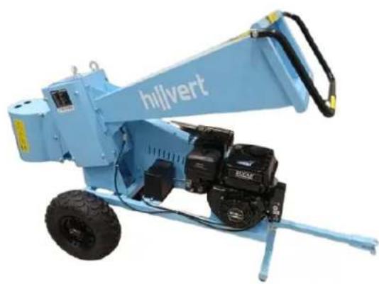
natural_image
Blue Hilvert industrial machine with attached motors and wheels (no visible text or symbols)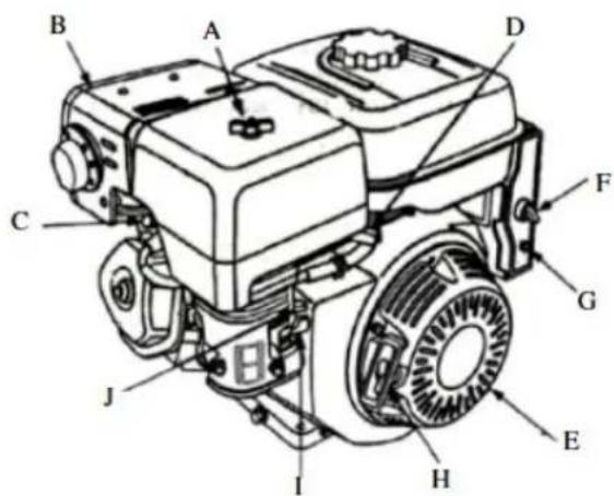
text_image
Technical diagram of a diesel engine with labeled components from A to J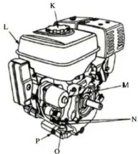
text_image
K L M N P Onatural_image
Collection of various bicycle lifters and equipment including wheelsets, wheels, and accessories (no text or symbols visible)HT-WBL-01
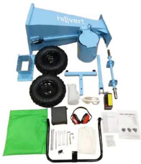
natural_image
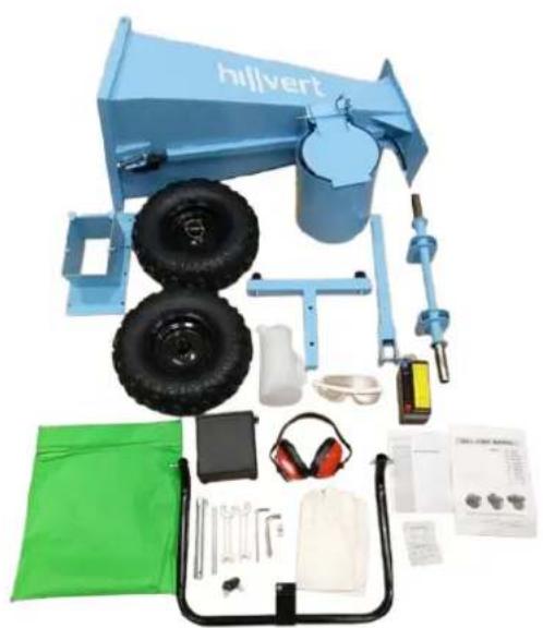
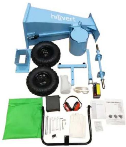
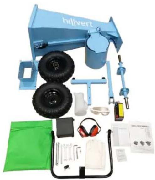
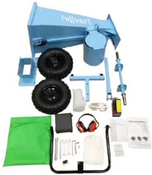
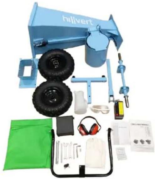
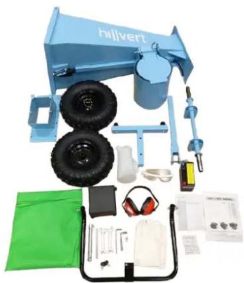
Collection of outdoor equipment including a blue Hilvert truck, tire, gear, and safety gear (no visible text or symbols)HT-WBL-02
text_image
Technical diagram of a mechanical assembly with numbered components and labeled partstext_image
Technical diagram of a wheeled cart with numbered components and dimension annotationstext_image
Technical diagram of a mechanical device with numbered components and dimension annotationstext_image
Technical diagram of a mechanical assembly with numbered components and labeled partstext_image
Technical diagram of a vehicle chassis with numbered components for identificationtext_image
Technical diagram of a mechanical device with numbered components, likely an agricultural or industrial machine.text_image
Diagram of an automotive electrical switch with labeled components and wiring connectionstext_image
Technical diagram showing a mechanical assembly with a tool interacting with a component, alongside a schematic of a device with directional arrows and a fish.natural_image
Mechanical component diagram showing a valve assembly with a curved arrow indicating direction (no text or symbols present)text_image
Technical diagram showing three labeled components (A, B) of a mechanical assembly with directional arrows indicating motion or movement.natural_image
Mechanical assembly diagram showing a valve mechanism with bolts and a base component (no text or labels)natural_image
Technical line drawing of a mechanical assembly with no visible text or symbolstext_image
Technical diagram of a mechanical device with labeled parts 31 and 36, showing gears and wheels.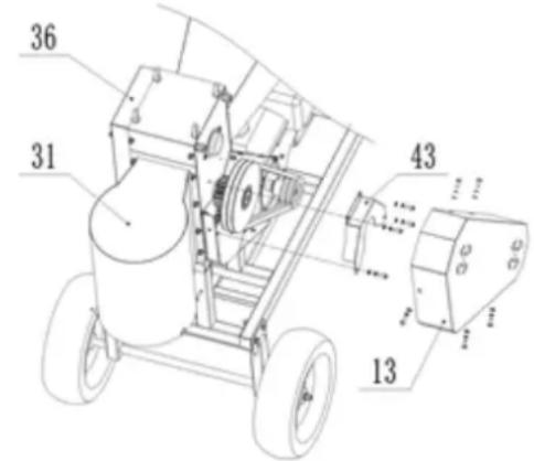
text_image
Technical diagram of a mechanical device with numbered components and labeled partsThis User Manual has been translated using machine translation. We have made every effort to ensure the translation is accurate, but please note that automated translations are not perfect and are not meant to replace human translators. The official version of the User Manual is in English. Any differences between the translated version and the original English are not legally binding. If you have any questions about the accuracy of the translation, please refer to the English version, which is the official reference. More language versions are available upon request via info@expondo.com
Technical data
| Parameter description Parameter value | |||
| Product name | Wood branch logger | ||
| Model | HT-WBL-01 | HT-WBL-02 | |
| Engine type | DH457Naturally aspirated1-cylinder OHV 4-strokeair cooled457 ccmEuro 5 | DH212Naturally aspirated1-cylinder OHV 4-strokeair cooled212 ccmEuro 5 | |
| Max power [HP] | 18 at 3600 rpm | 7 at 3600 rpm | |
| Max torque [Nm] | 31 at 2500 rpm | 13.5 at 2500 rpm | |
| Fuel type | Unleaded gasoline min. 91 octane (RON) ≤E10 | ||
| Engine oil | Viscosity | Standard ambient working conditions:API SJ +higher 10W30 (with cleaning additives) | |
| Cold ambient working conditions (not exceeding 0°C):API SJ +higher 5W30 (with cleaning additives) | |||
| Capacity [L] | 1.1 | 0.6 | |
| Spark plug | Type | F7TC / F7RTC (or equivalent) | |
| Electrode gap [mm] | 0.6-0.8 | ||
| Tightening torque[Nm] | 18-22 | ||
| Fuel tank capacity [L] | 6.5 | 3.6 | |
| Starter type | Recoil / Electric | ||
| Blade max speed [rpm] | 230 | 240 | |
| Chipping capacity [cm] | 12 (soft fresh branch) | 7 (soft fresh branch) | |
| Allowable log dimeter [cm] | ∅10-30 | ∅8-20 | |
| Dimensions [width x depth x height; mm] | 850 x 2120 x 1410 | 640 x 1800 x 1120 | |
| Weight (netto) [kg] | 249 | 112 | |
| Battery type | 6MF9GEL 12 V 9 Ah | 6MFLGEL 12 V 9 Ah | |
1. Use guidelines
The device is designed for processing of wood branches, shrubs, weeds, shoots (with a diameter not exceeding the value given in the technical data table) into smaller pieces. These machines are powered by a gasoline engine, making it portable and suitable for outdoor use, especially in areas without access to electricity and equipped with a hitch for low-speed ( ≤ 5 km/h) towing outside public roads only.
CAUTION: do not use the machine to shred construction debris, plastic, paper products, ropes or strings, or any material that may contain metal.
WARNING: remove all nails, ropes, strings, or stones that may be embedded in plant parts (e.g., roots, etc.) before inserting material into the unit.
The user is liable for any damage resulting from unintended use of the device.
3.1. Device description
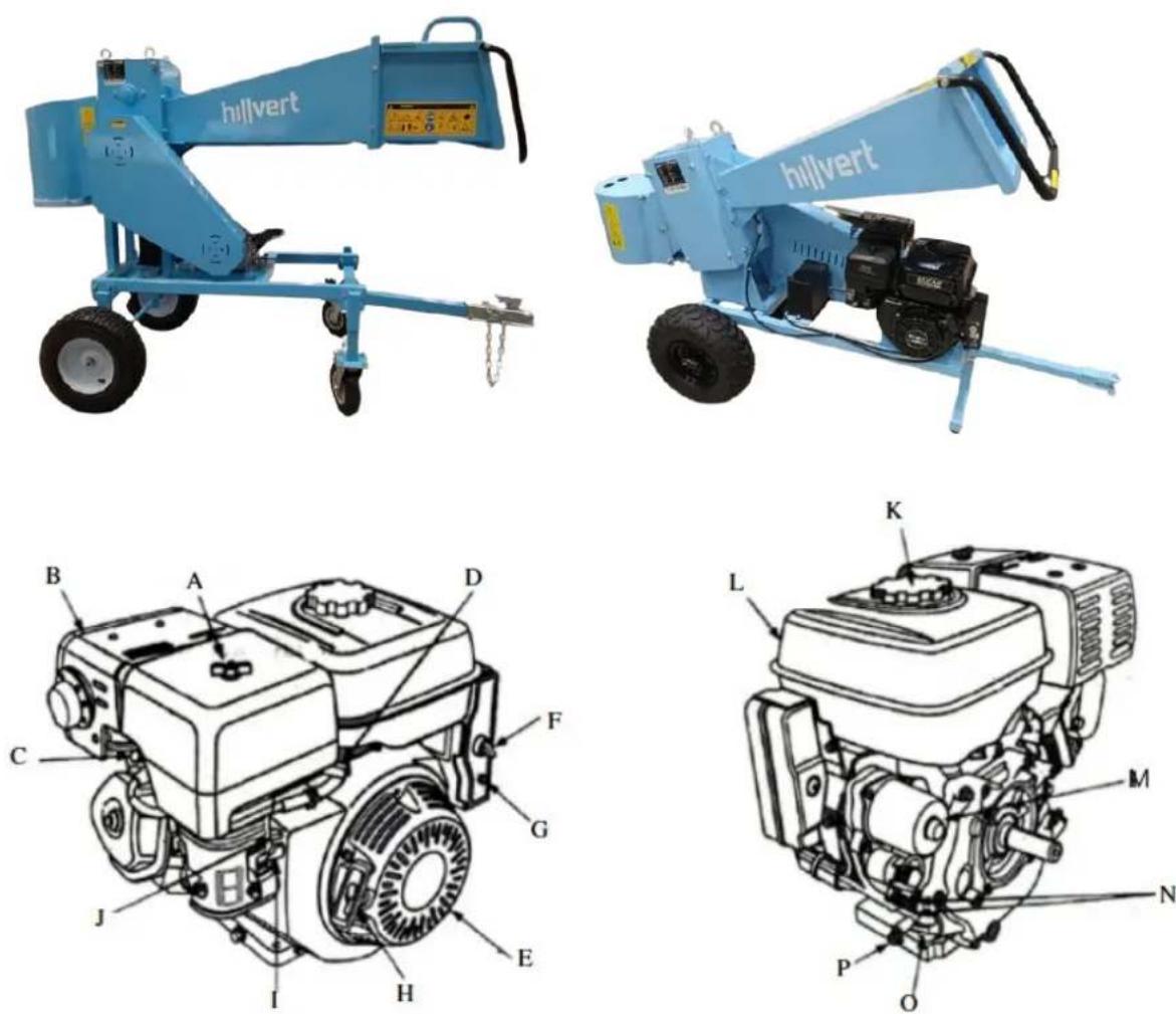
A. Air cleaner
B. Muffler
C. Muffler Guard (Optional)
D. Spark plug
E. Throttle lever
F. Ignition switch
G. Breaker (electric starter type)
H. Recoil starter handle
I. Choke lever
J. Fuel cock
K. Fuel filler cap
L. Fuel tank
M. Starter (electric start type)
N. Engine identification number
O. Oil dipstick
P. Oil drain plug
3.2. Preparing for use
APPLIANCE LOCATION
The ambient temperature must not exceed 45^ C and ambient humidity should not exceed 85%. Use the unit only in open spaces and/or well-ventilated areas. Do not obstruct the air inlet of the unit and the exhaust outlet of the engine. Keep the unit away from any hot surfaces. Always operate the unit on a level, stable, clean, fireproof surface and out of the reach of children and persons with impaired mental, sensory, and intellectual functions. The place of operation of the device should provide easy access to the emergency shutdown lever of the device. It is prohibited to work or run the machine it on non-paved surfaces with slopes, undulations, bumps, looseness, or slippery surfaces.
WORKING CONDITIONS
Check the material to be shredded and make sure that there is enough space above the machine to load the material. It is recommended to choose a workplace as close as possible to where the chips are to be used. This will reduce the need to carry the processed material to a minimum.
Keep a safe distance from the chip discharge area. Make sure that all bystanders, children, animals, or valuables are also kept at a safe distance from the chip discharge area.
ASSEMBLY OF THE MACHINE
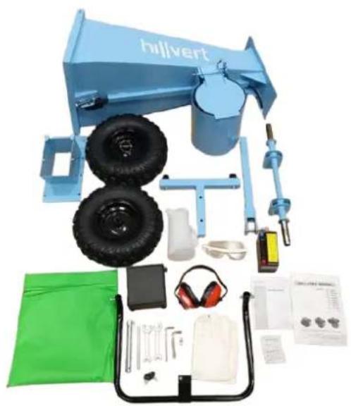
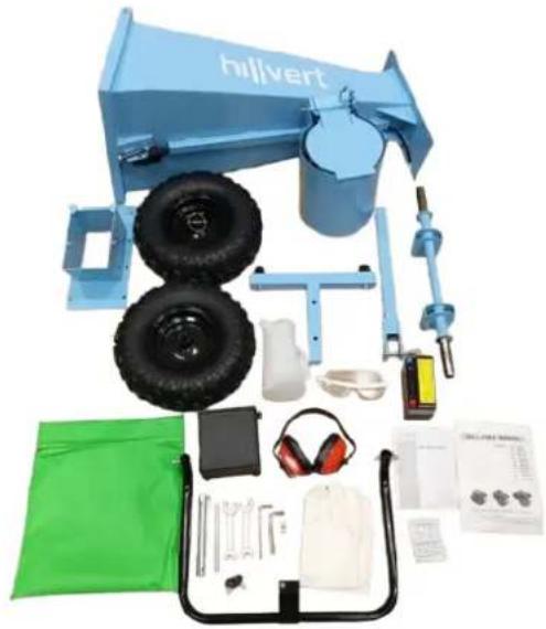
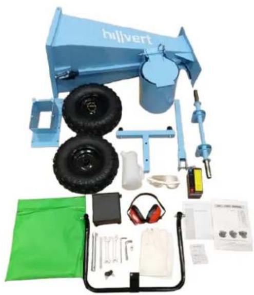
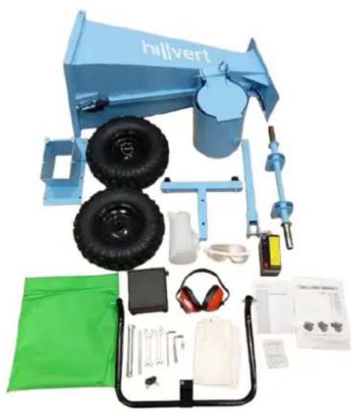
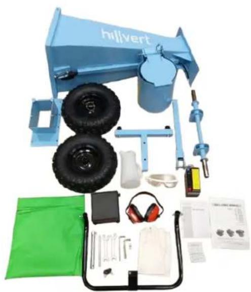
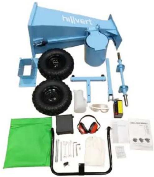
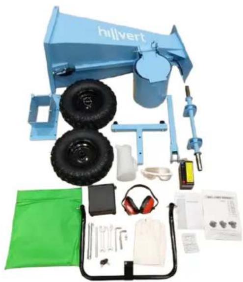
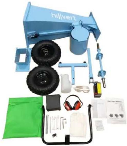
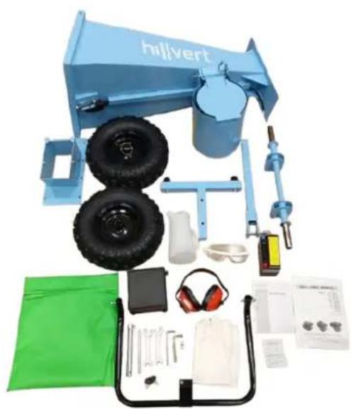
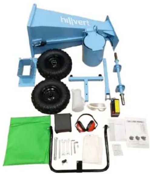
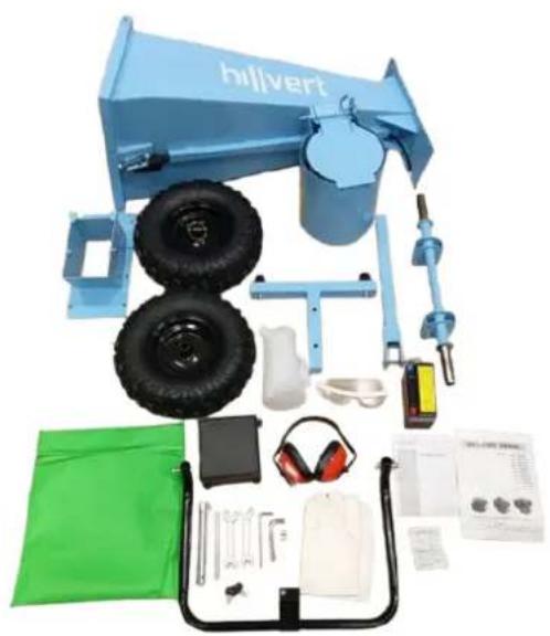
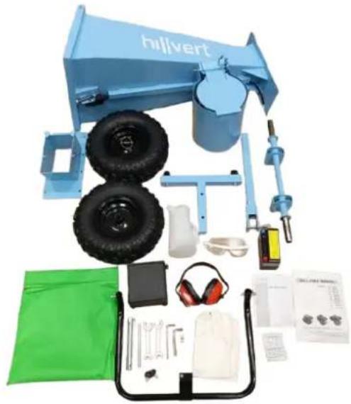
This machine is partially disassembled and packed. After unpacking, the parts are taken out of the packaging box and simply assembled according to the attached installation diagram before operating. Attention: Some parts of this machine with large volume and heavy weight. During assembly, it is recommended to seek guidance and assistance from a seller or someone with considerable knowledge and ability to this machine to ensure safety.
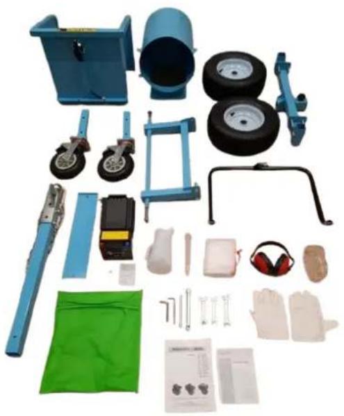
natural_image
Collection of blue industrial equipment including wheel, lift, guide rails, and safety gear (no text or symbols visible)HT-WBL-01
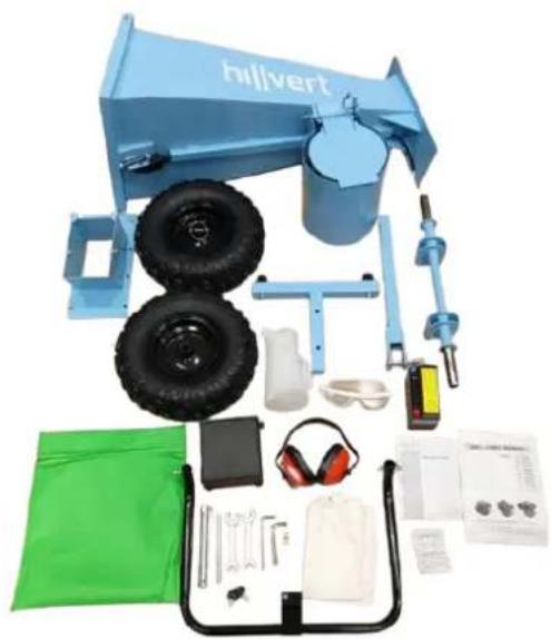
natural_image
Assorted blue and green mechanical components including a Hilvert truck, tires, sensors, and gear (no visible text or symbols)HT-WBL-02
CAUTION: during installation, do not put hands or any other body parts within a radius of blade rotor; Do not touch the blades with your hands or any other body parts.
HT-WBL-01
A. Upper part of feed hopper assembly
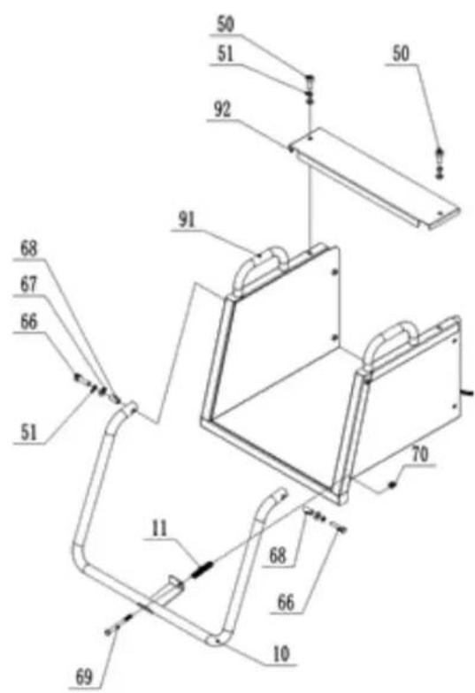
text_image
Technical diagram of a mechanical assembly with numbered components, likely a device or enclosure with labeled parts.| Part number | Part description |
| 92 | Top cover for upper part of feed hopper |
| 91 | Upper part of feed hopper |
| 70 | Lock nut |
| 69 | Bolt |
| 68 | Bushing |
| 67 | Washer |
| 66 | Bolt |
| 51 | Spring washer |
| 50 | Bolt |
| 11 | Spring |
| 10 | Safety bar |
Firstly, install the safety bar 10 as shown in the figure by hardware and spring to fix it onto the upper part of feed hopper 91. Then install top cover for upper part of feed hopper 92 onto the upper part of feed hopper 91 by bolt 50, and wait for the next installation step.
B. Front wheels assembly
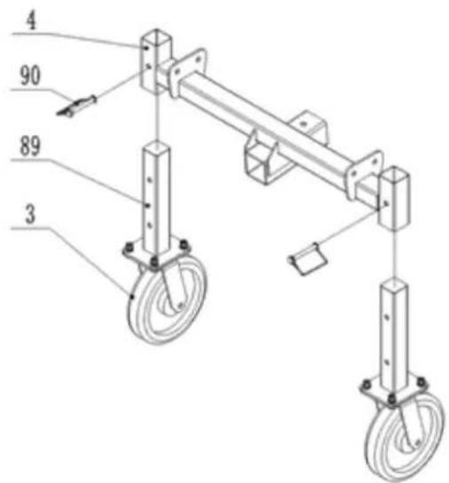
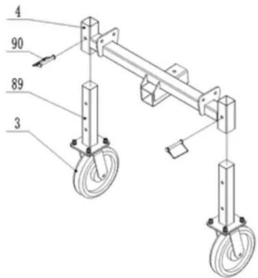
text_image
4 90 89 3| Part number | Part description |
| 90 | D-pin |
| 89 | Front wheel foot |
| 4 | Front wheels frame |
| 3 | Omni-directional wheel |
Install front wheel foot 89 as shown in the figure onto the front wheel frame 4 by D-pin 90, and wait for the next installation step.
C. Back wheel frame assembly
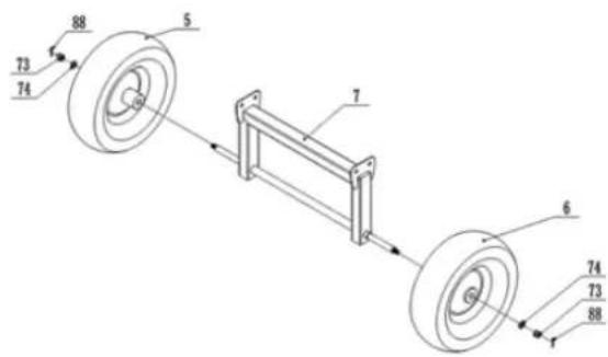
text_image
73 74 88 5 7 6 74 73 88| Part number | Part description |
| 88 | Pin |
| 74 | Washer |
| 73 | Lock nut |
| 7 | Back wheel frame |
| 6 | Right wheel |
| 5 | Left wheel |
Install the left and right tires 5 and 6 onto the back wheel frame 7 with hardware and wait for the next installation step.
D. Front wheels/ back wheel frame/main frame assembly
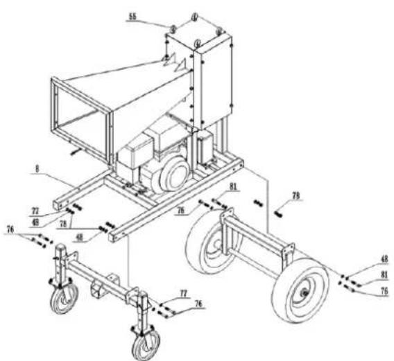
text_image
Technical diagram of a wheeled cart with numbered components and dimension annotations| Part number | Part description |
| 81 | Bolt |
| 78 | Lock nut |
| 77 | Washer |
| 76 | Bolt |
| 51 | Spring washer |
| 55 | Eyebolt – for lifting |
| 48 | Spring washer |
At least two eyebolts 55 should be selected as the main lifting points, lift main frame 8 slowly to a height of 50-70cm above the ground with a lifting device with a lifting capacity of over 1000kg, paying attention to safety. As shown in the above figure, Front wheels and back wheel frame can be fixed on the main frame 8 by hardware.
E. Outlet hopper/ upper part of feed hopper/main frame assembly
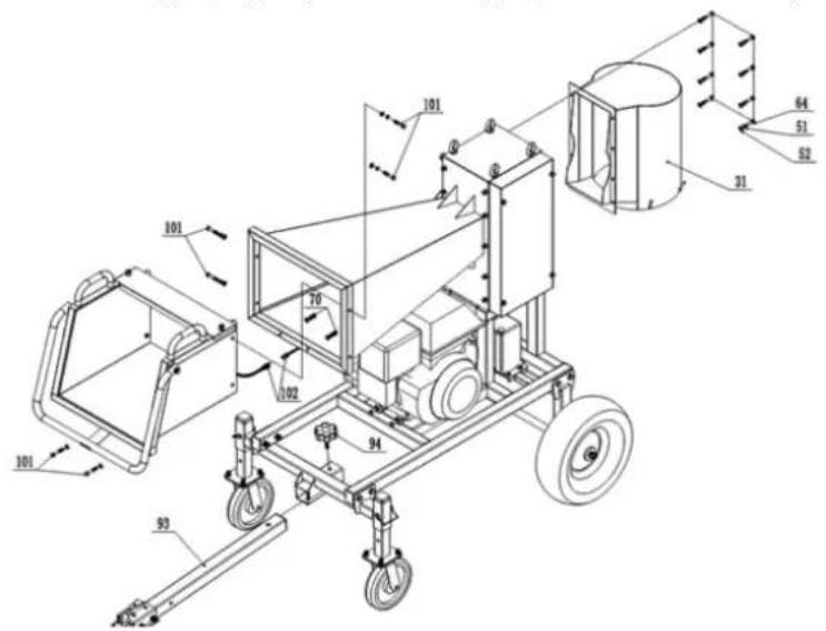
text_image
Technical diagram of a mechanical device with numbered components and labeled parts| Part number | Part description |
| 102 | Wire |
| 101 | Bolt |
| 94 | Knob |
| 93 | Tow bar |
| 70 | Lock nut |
| 64 | Bolt |
| 52 | Washer |
| 51 | Spring washer |
| 31 | Outlet hopper |
Fix finished upper part of feed hopper 91 and outlet hopper31 on main frame by hardware; Connect wire 102 to engine control wire., pull out the left pin on the safety switch on safety bar 10. Fix tow bar 93 by knob 94 on the frame.
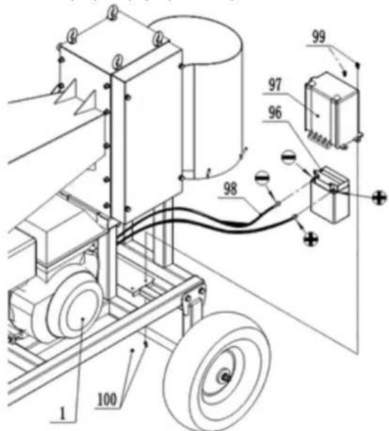
F. Battery assembly and connection
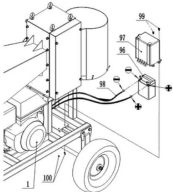
text_image
Technical diagram of a mechanical assembly with numbered components and labeled parts| Part number | Part description |
| 100 | Lock nut |
| 99 | Bolt |
| 98 | Battery wire |
| 97 | Battery cover |
| 96 | Battery |
| 1 | Engine |
Connect the positive and negative wires of battery wire 98 to the positive and negative poles of battery 96, with the positive pole connected to the positive pole and the negative pole connected to the negative pole. Do not connect them incorrectly, otherwise it will damage the battery and engine Fix battery cover 97 on battery 96, and locked them on the frame by bolt 99.
HT-WBL-02
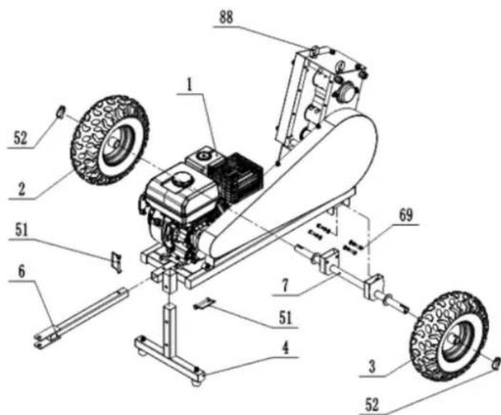
A. Frame assembly
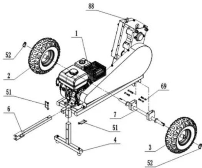
text_image
Technical diagram of a vehicle chassis with numbered components and tire placementsTwo eyebolts 88 should be selected as the main lifting points, lift main frame slowly to a height of 40-60 cm above the ground with a lifting device with a lifting capacity of over 300kg, paying attention to safety! Install T-bar 4, tow bar 6, axle 7 and wheels (2&3) by D-pin 51, 52, and bolt 69 and hardware.
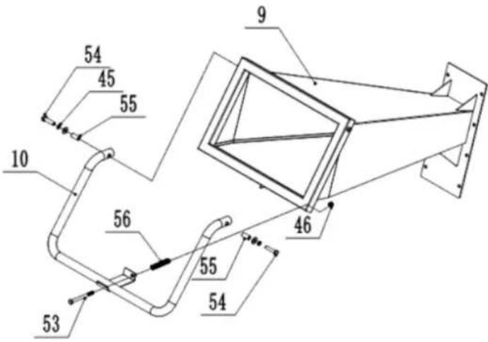
B. Feed hopper assembly
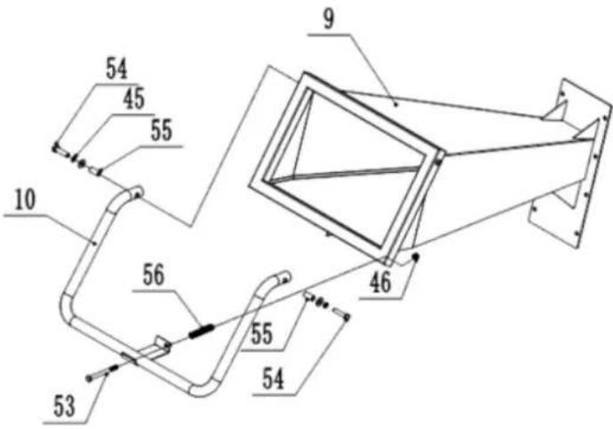
text_image
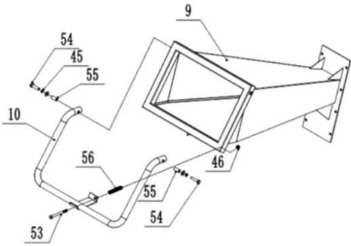
54 45 55 10 56 53 9 46 55 54Install safety bar 10 on the feed hopper 9 by bolt 53,54 and hardware.
C. Outlet hopper assembly
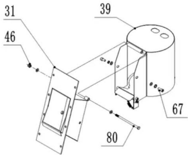
text_image
31 46 39 67 80Install outlet hopper on upper outlet hopper 31 by bolts and hardware.
D. Feed/outlet hopper and main frame assembly
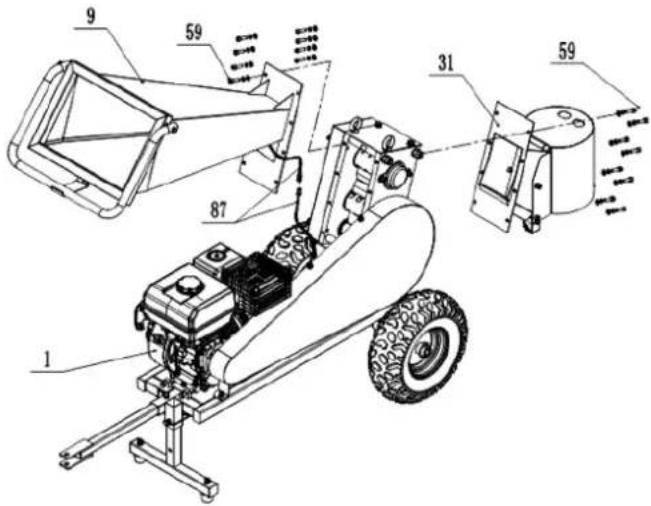
text_image
Technical diagram of a mechanical device with numbered components and airflow indicatorsInstall feed hopper 9 and outlet hopper 31 by bolts and hardware. Connect safety wires 87 with engine, pull out the reset pin on the switch (left side on switch) for start.
FILLING THE ENGINE OIL
During transport, the engine of the machine is without oil, therefore it must be topped up before the first start-up. Only use fresh oil in accordance with the recommendation for lubricating the engine (see the technical data table):
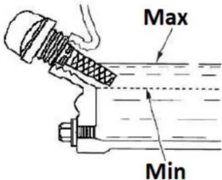
text_image
Max Min- Place the machine on a level, horizontal surface.
- Unscrew the orange engine oil filler cap (with a built-in dipstick - see the above picture) and pour oil through its opening (use a funnel, for example), taking care not to pour more than the permissible level (marked field on the dipstick), which we check on the dipstick of the cap after it is fixed in the hole.
- It is recommended to keep the level closer to the upper than the lower acceptable limit. In case of overflowing beyond the permissible level, excess oil can be sucked out through the plug hole. ATTENTION: operating the engine with the wrong oil level can lead to engine damage! Check the engine oil level before each machine operation when the engine is still cold.
REFUELING
ATTENTION: The engine of the device is adapted only to burn unleaded gasoline without oil admixtures. The use of other fuel that is not fresh and with too high an ethanol content or of low quality can lead to engine failure. Refuel only with the engine off, paying close attention not to spill fuel over the engine, especially when it is hot - risk of fire! If the engine is warmed up, wait at least 2 minutes before refueling.
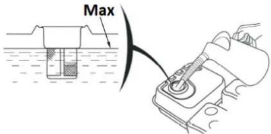
text_image
Max- Place the machine on a level, horizontal surface.
• The fuel tank is located on the top of the unit.
- Unscrew the fuel filler cap (with the dispenser icon). Do not pull out the strainer filter inside the opening!
- Refill fuel through the plug opening - the maximum fuel level in the tank should not exceed the upper limit of the red level gauge in the strainer filter, i.a. reach the bottom of the filler neck as max.
BATTERY CONNECTION
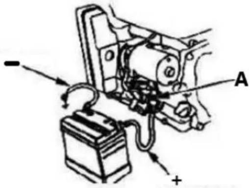
CAUTION: Be careful not to connect the battery in reverse polarity, as this will short circuit the battery charging system!
- Connect the positive/red (+) cable to the starter solenoid terminal (A).
- Connect the negative/black or blue (-) cable to an engine mounting bolt or other good engine ground connection.
- Connect the positive (+) cable to the positive (+) terminal.
- Connect the negative (-) cable to the negative (-) terminal.
• Coat terminals and cable ends with copper or special electric terminal grease.
text_image
Technical diagram of an automotive electrical component with labeled parts A and a battery, showing wiring and grounding.3.3. Device use
3.3.1 Startup
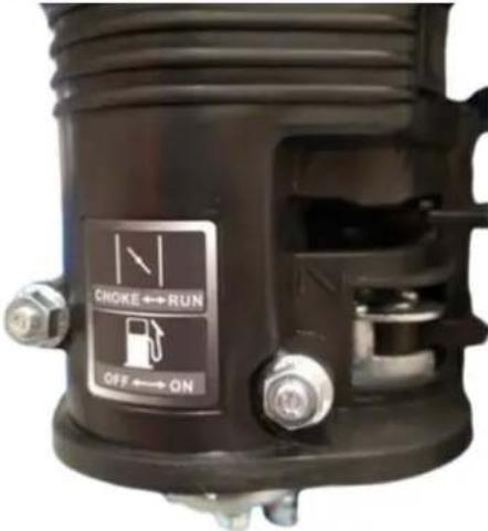
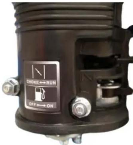
- Set the fuel valve - distributor icon - to the open position ("ON" - see the signature pictogram on the air filter housing) so that fuel can flow from the tank to the carburetor to start the engine.
text_image
CHOKE ↔ RUN OFF ↔ ON- Only when the engine is cold: activate the choke, i.e. set the manual suction lever to the closed position ("CHOKE") - see the universal icon.
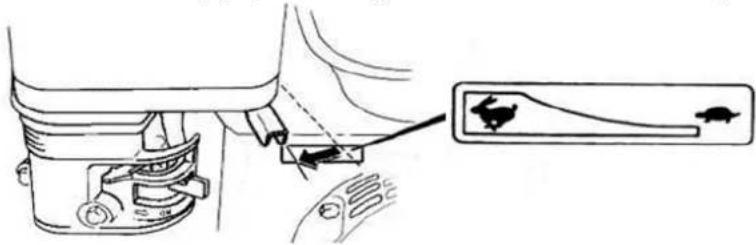
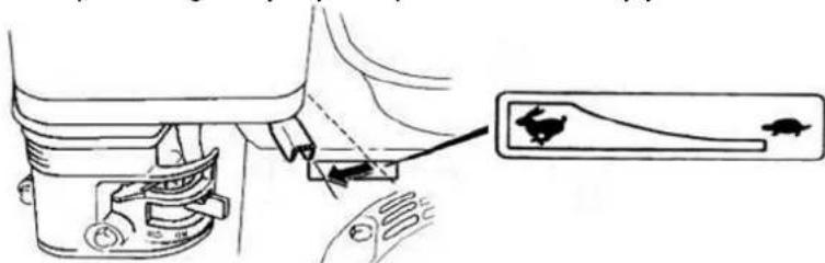
- Set the throttle lever - engine speed control - to approx. 1/2 scale in the direction of fast rotation. NOTE: the rabbit icon symbolizes fast rotation and the turtle is for slow speeds, so by moving the lever towards the appropriate icon, you increase or decrease the engine speed.
natural_image
Technical line drawing of a mechanical component with a close-up inset showing a curved arrow and fish (no text or symbols)- Turn the ignition (key) on the engine from the "OFF" to the "ON" position (HT-WBL-01 only) and then to "START" (or crank icon) so that the engine can be started – after the starts, immediately release the ignition key.
- [alternatively - manually] After putting the ignition key to the "ON" position, grasp the lever of the recoil starter rope and pull in a steady motion until you feel resistance on the lever, then with a quick movement pull to the end, all the while holding the handle in your hand allowing it to return to the starting position in a controlled manner. Sometimes in freezing conditions, it may be necessary to pull the tug handle several times before the engine starts - this is normal.
ATTENTION: old or low-quality fuel can lead to starting problems! Change it immediately to a proper, fresh one. - After starting the engine, let it work for a bit in order to reach the operating temperature after approx. 1 minute and during this time gradually move the manual suction lever in the direction of off ("RUN").
NOTE: starting a warmed-up engine does not require switching on the suction - its lever should be in the open position.
IMPORTANT: low speed is only for idling the engine - use the highest speed when operating the machine.
3.3.2 Stopping
- Set the slowest engine speed with the throttle lever (move it towards the turtle icon) and let the engine run at low speed for 1-2 minutes to cool it down a bit.
- Turn off the ignition by setting its switch to the "OFF" position. Alternatively, you can close the fuel valve (switch to the "CLOSE" position) and wait for the engine to stop - this method will get rid of residual fuel from the carburetor, so it is worth using it before storing an unused machine for a long time.
ATTENTION: if you need to stop the device suddenly, press the emergency stop button but use this method only in an emergency!
IMPORTANT: never use the choke lever to stop the engine by throttling it!
- If the machine will not be used any further, then close the fuel supply valve - set its lever to the closed ("CLOSE") position.
3.3.3 Work tips
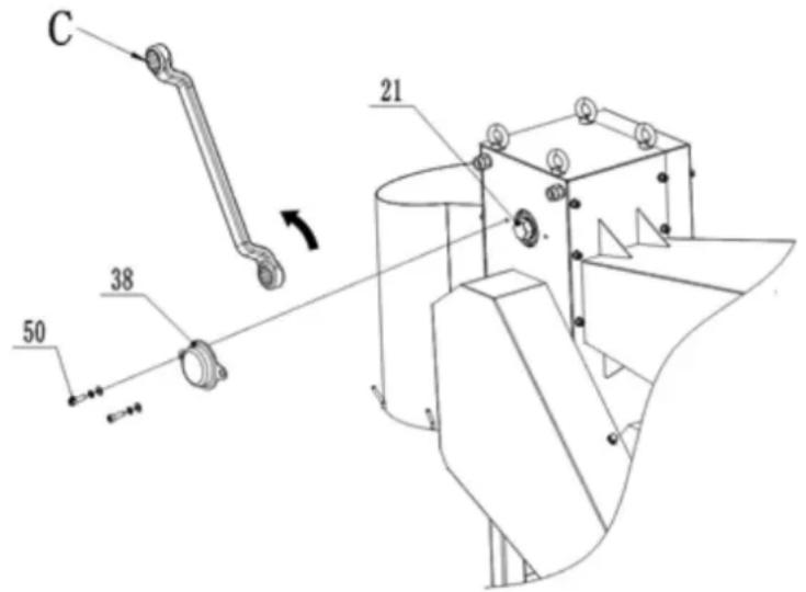
- [HT-WBL-01] If the machine is stopped during working and the wood is stuck on the blade and cannot be cut off, please unscrew the bolt 50 and remove the shaft cover 38. Use a tool wrench C with a diameter of 34 mm on the opposite side to clamp the hexagonal body on the blade shaft 21. Turn the upper blade shaft 21 counterclockwise to release the blade from the wood. Remove the stuck wood and fix the shaft cover 38 before restart the machine:
text_image
C 21 38 50- [HT-WBL-02] If the machine is stopped during working and the wood is stuck on the blade and cannot be cut off, please unscrew the bolt 67 and remove the shaft cover 38. Use a tool wrench C with a diameter of 30mm to clamp the hexagonal body on the blade shaft 21. Turn the upper blade shaft 21 counterclockwise to release the blade from the wood. Remove the stuck wood and fix the shaft cover 38 before restart the machine.
- This machine can cut unsorted or preprocessed branches, so fresh cut branches, plant stems, etc. can be directly for cutting. Due to factors such as raw material type, moisture content, and hardness, the machine may experience engine overload, stalling, and body shaking during working which is a normal situation.
- If it is necessary to cut down hard perennial trees or dry wood, the feed diameter should be reduced to prevent engine overload and shutdown, and to reduce damage to the engine, blades, and other components of the vehicle. This machine has the best cutting effect on fresh cork.
- Please ensure that the position below the discharge port is open and there are no other situations that may affect the discharge before working.
- Feed the material on both sides in front of the feeding hopper, do not operate directly towards the machine's feeding port. When feeding, do not vigorously hold the wood, just gently push the wood in; cleaning and collection operations directly below the discharge port are forbidden.
- Due to the processing characteristics of this machine, the user only needs to gently push the wood into the feeding hopper. After the raw wood is fed into the feeding hopper, it will continue to fully process the entire section of raw material until the end, without any operation by the user. However, stopping midway can cause incomplete cutting of the wood and blade jamming. Therefore, in non-emergency situations, this machine is not allowed to touch the safety bar and is not allowed to stop midway during work. In addition, short block wood materials should not enter the feed hopper for cutting, as they will break horizontally in the wooden box during cutting, causing engine overload and shutdown, and even causing damage to blades or other parts of the machine.
- [HT-WBL-01] The discharge port is equipped with hooks for collection bags, but collection bags can only be placed if the following two conditions are met:
a) The placement and replacement of the collection bag are operated by a dedicated person. After placement, the collection bag should be lower than the lower edge of the discharge port, making it easy to observe the stacking status of wood inside it. This ensures that the collection bag can be detected in a timely manner after filling without causing blockage at the discharge port, and is quickly removed and replaced with a new collection bag in a timely manner.
b) If single user operates alone and requires a collection bag to collect wood logger, it is necessary to ensure that the collection bag can completely hold the entire volume of the raw wood, ensure that the wood does not overflow inside the collection bag, and prevent serious damage to important components such as the blade and blade shaft due to the blockage of the discharge port caused by the overflow of wood inside the collection bag.
3.4. Cleaning and maintenance
a) Engine service interval table (unless otherwise specified by the manufacturer of the engine unit):
| Activity / Interval * | Before each use | After 1 month or the first 20 man-hours from 1. commissioning | Every 3 months or every 50 operating hours | Every year or 100 working hours | ||
| Engine oil | Inspection of possible supplement | x | ||||
| Replacement x | ** x | |||||
| Air filter *** | Control | x | ||||
| Cleaning | x | |||||
| Replacement | x | |||||
| Cleaning the fuel drop tank | x | |||||
| Control and if necessary, adjusting the spark plug gap | x(replacement if necessary) | |||||
| Fuel tank - cleaning | x | |||||
| Check the sharpness of the knives/splines | x | |||||
| Tire pressure | x | |||||
| Clean the outside of the engine (tarnish, dust, etc.) | x | |||||
| Fuel hoses - inspection | Every 2 years(replacement if necessary) | |||||
| Cleaning the inside of the cylinder head or piston from carbon build-up **** | Every 125 hours of operation | |||||
| * Depending on what falls sooner. | ||||||
| ** If the machine works frequently under load or in extremely hot ambient conditions - reduce the interval to 25 working hours. | ||||||
| *** If the machine often works in a dusty, dirty environment, the cleaning interval should be reduced to 10 working hours, and replacement every 25 working hours. | ||||||
| ****The service must be performed by a specialist. | ||||||
b) Before each cleaning, adjustment or replacement of accessories, and when the unit is not in use, turn off the machine and cool it down completely, also remove the ignition cable pipe from the spark plug.
- Wait until the rotating parts stop.
c) Use only non-corrosive cleaning agents for cleaning the surfaces.
d) Store the unit in a dry and cool place protected from moisture and direct sunlight.
e) Do not spray the unit with a stream of water or immerse it in water.
f) Make sure that no water enters through the ventilation openings in the casing.
g) Clean the ventilation openings with a brush and compressed air.
h) Perform regular inspections of the unit checking technical fitness and any damages.
i) Do not use sharp and/or metal objects (e.g. wire brush or metal spatula) for cleaning as they may damage the surface of the appliance material.
j) Check the fuel cables regularly for any damage or wear (cracks or leaks) and replace the damaged component immediately.
k) Spark plug inspection/replacement:
ATTENTION: remove the plug only on a cold engine!
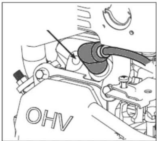
Access to the plug is between the air filter housing and the muffler. First, remove the ignition cable pipe from the spark plug to gain access to it. Before installing a spark plug - including a new spark plug - check the spark plug gap and adjust it if necessary. When screwing in the plug, do so as far as it will go, but tighten it sensitively - usually another 1/3-1/2 turns (see the plug manufacturer's recommendations).
The rest of the assembly reverses to disassembly.
natural_image
Mechanical component diagram showing a propeller and valve assembly (no text or symbols)I) Checking/replacing the air filter:
text_image
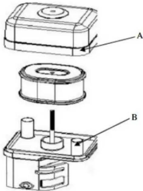
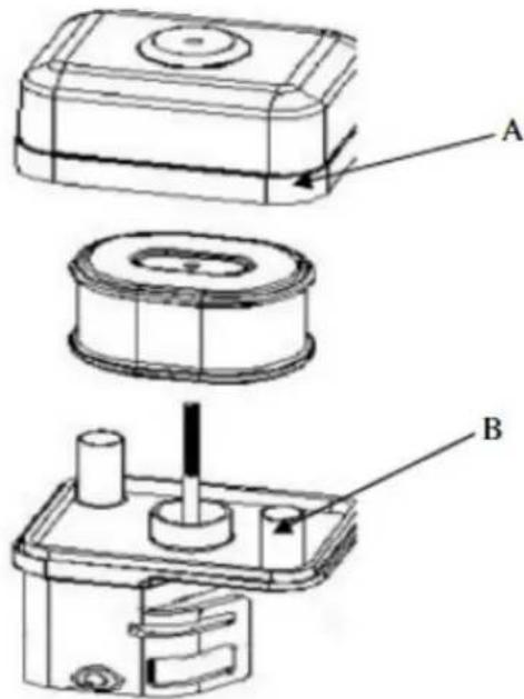
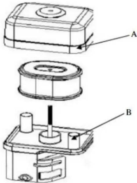
Technical diagram showing three labeled components (A, B) of a mechanical assembly with directional arrows indicating motion or movement.- Remove the air cleaner outside cover (A). Be careful to prevent dirt and debris from falling into the air cleaner assembly.
• Separate the Air Filter (A) from the Air Filter Housing (B). - Inspect the air filter. Clean dirty air filter with warm water and mild soap. Allow air filter to dry thoroughly before re-installation.
• Install the air filter assembly onto the carburetor and secure with screw. - Note: Do not use pressurized air or solvents to clean the filter. Pressurized air can damage the filter and solvents will dissolve the filter.
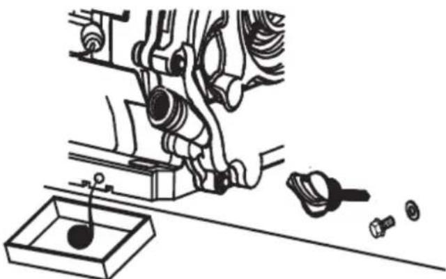
m) Changing the engine oil:
natural_image
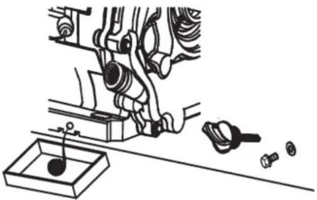
Mechanical assembly diagram showing a valve mechanism with bolts and a base component (no text or labels)- Place the machine on a flat surface, switch on the machine and warm up the engine for a few minutes, then switch it off.
- Remove the oil filler cap with the dipstick.
- Put the oil slick container under the engine at the drain plug.
• Unscrew the oil drain plug and drain all the oil - until it stops leaking. - Turn the drain plug back on and refill it with fresh oil through the filler plug with a dipstick according to the procedure described earlier in this manual.
n) Prolonged non-use of the machine:
If the machine is not used for more than a month, it is necessary to:
- Empty the fuel from the tank or add a fuel stabilizer to it according to the manufacturer's proportion of the additive.
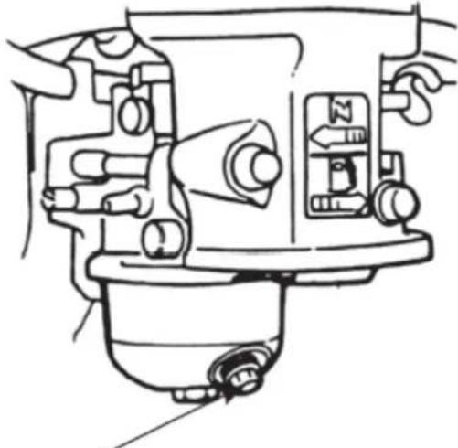
NOTE: do not keep fuel in a tank with a stabilizer for longer than the manufacturer of the additive recommends! - (only if the fuel is emptied from the tank) Start the engine and let it run without load until it shuts down on its own due to lack of fuel - this will allow the residual fuel to empty from the fuel system and carburetor. Any residue can be drained by unscrewing the precipitation filter;
natural_image
Technical line drawing of a mechanical assembly with no visible text or symbols• Turn off the precipitation filter and close the fuel valve.
- Replace the engine oil with fresh oil (if it has not been changed recently or shows signs of wear).
- On a cold engine, remove the ignition wire pipe from the spark plug and unscrew the spark plug and pour 5-10 ml of fresh engine oil into the cylinder through its opening. Screw the spark plug back in.
- Pull the starter tug handle until you feel resistance so that the oil is distributed in the cylinder preserving the engine from the inside. Next, make 8-10 slow movements with the pull as if you wanted to start the engine.
• Clean the device, especially the engine, from dirt and other contaminants such as dust.
• Inspect the machine for worn or damaged parts - replace them if necessary.
- If necessary, inflate the air in the wheels to the maximum allowable pressure (see the marking on the tire).
- Store the machine in a dry, roofed building with good ventilation and away from heat and sunlight.
o) Please inspect the machine parts under the guidance of professionals or professionals regularly with 1-2 times monthly. Ensure the machine completely stopped!
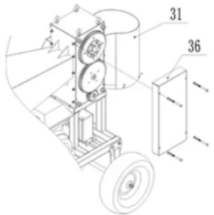
- [HT-WBL-01] Open the gear cover 36, belt cover 13, gear small cover 43 and discharge port 31, give an appropriate amount of lubricating grease to each gear component; Check for flexible rotation and wear of key parts such as bearings, blades, belts, etc. If defects are found, they should be promptly repaired before rework. Especially for blades, regular inspections are required and blade repairs are carried out at professional institutions. A blunt blade can reduce the efficiency of the machine, and in severe cases, it can cause damage to machine components.
text_image
Technical diagram of a mechanical device with labeled parts 31 and 36, showing gears and wheels.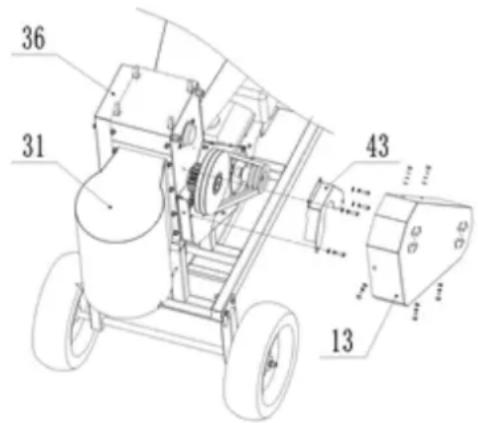
text_image
36 31 43 13- [HT-WBL-02] open the gear cover 36 by removing the 4x holding it b77 bolts. Grease each gear component; Check for flexible rotation and wear of key parts such as bearings, blades, belts, etc. If defects are found, they should be promptly repaired before rework. Especially for blades, regular inspections are required and blade repairs are carried out at professional institutions. A blunt blade can reduce the efficiency of the machine, and in severe cases, it can cause damage to machine components.
SAFE REMOVAL OF BATTERIES
GEL 12V 9Ah batteries are installed in the devices.
Remove used battery from the device using the same procedure by which you installed them.
Recycle batteries with the appropriate organisation or company.
DISPOSING OF USED DEVICES
Do not dispose of this device in municipal waste systems. Hand it over to an electric and electrical device recycling and collection point. Check the symbol on the product, instruction manual and packaging. The plastics used to construct the device can be recycled in accordance with their markings. By choosing to recycle you are making a significant contribution to the protection of our environment.
Contact local authorities for information on your local recycling facility.
TROUBLESHOOTING
| Problem | Possible cause |
| The engine cannot be started | Is the ignition switch in the “ON” position?Is the fuel shut-off valve on?Are you using fresh, clean gas? If the gas is old, change it.Use a fuel stabilizer if you keep gas longer than 30 days.Is the spark plug clean? If the spark plug is dirty or cracked, change it. If it’s oily, leave it out, hold a rag over the plug hole and pull the recoil cord several timesto blow out any oil in the cylinder, then wipe off the plug and reinsert it.• if the safety switch is reset and wire is connected? |
| The engine stop during working | • if the engine is stopped by overloading?• if wood is blocked in blade house?• if the safety switch is in normal condition?• if the engine with enough fuel and oil? |
| Strange noise | • Stop the machine, check if any hardware gets loose?• if not, ask the professionals to check and do maintenance. |
| The blade worn or damaged | • Go to the professional repair sites to change or sharp the blades. |
| Belt slipping | • immediately stop the machine, ask professional staff to open the belt cover, check the wear of the belt, and if the belt is damaged, replace it with a new one; if the belt is normal, it is necessary to loosen the engine fixing bolts, adjust the front and rear positions of the engine to tension the belt, and then reinstall the belt cover after completion. |
| Wood logger fails to be separated effectively | • immediately stop the machine, ask professional staff to adjust the blade space (open the gear cover, loosen the bolts pressed onto the cone sleeve of the upper blade shaft and gear, rotate the upper blade shaft, adjust the relative position of the gear and blade shaft, select the appropriate gap between the upper and lower blades, lock the bolts on the cone sleeve, and then install the gear cover back) |

natural_image
Blue Hilvert agricultural machine with wheels and handle (no visible text or symbols)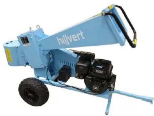
natural_image
Blue Hilvert industrial machine with attached motors and wheels (no visible text or symbols)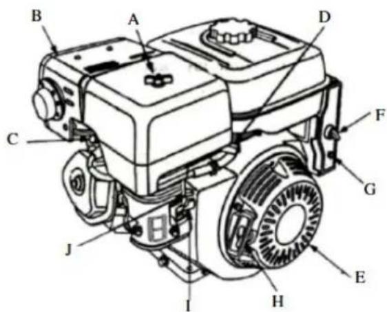
text_image
Technical diagram of a diesel engine with labeled components from A to J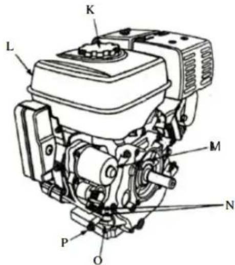
text_image
K L M N P Onatural_image
Collection of blue industrial equipment including wheel stators, lifters, and safety gear (no text or symbols visible)HT-WBL-01
natural_image
Product photo of a blue Hilvert electric vehicle with visible wheels, sensors, and accessories (no text or symbols)HT-WBL-02
text_image
Technical diagram of a mechanical assembly with numbered components and dimension annotationstext_image
Technical diagram of a wheeled cart with numbered components and dimension annotationstext_image
Technical diagram of a mechanical device with numbered components and labeled partstext_image
Technical diagram of a mechanical assembly with numbered components and labeled partstext_image
Technical diagram of a vehicle chassis with numbered components for identificationtext_image
Technical diagram of a mechanical device with numbered components and labeled partstext_image
Diagram of an automotive electrical switch with labeled components and wiring connectionstext_image
Technical diagram showing a mechanical assembly with a tool and a labeled component, including a schematic view of a device.text_image
Technical diagram showing three labeled components (A, B) of a mechanical device with internal parts and assembly details.natural_image
Mechanical assembly diagram showing engine components and a tool (no text or labels)natural_image
Technical line drawing of a mechanical assembly with no visible text or symbolstext_image
Technical diagram of a mechanical assembly with numbered components, including gears and wheels, labeled parts 31, 36, and 43.natural_image
Blue industrial machine labeled 'hilvert' with wheels and a handle (no visible text beyond label)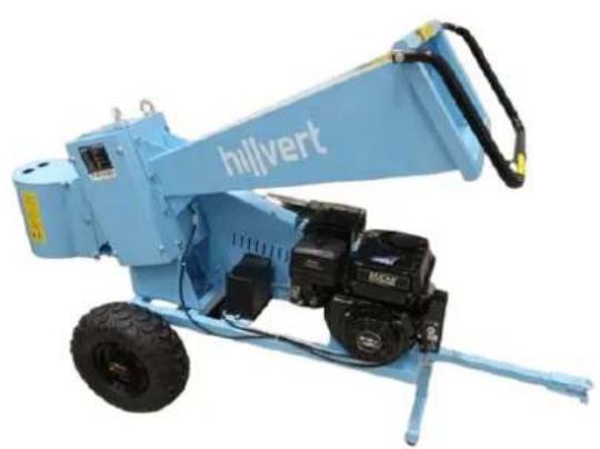
natural_image
Blue hillvert construction machine with attached motors and a handle (no visible text or symbols)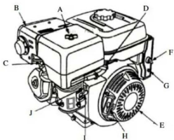
text_image
Technical diagram of a diesel engine with labeled components from A to J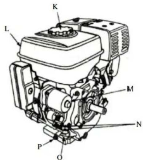
text_image
K L M N P Onatural_image
Collection of blue industrial equipment including wheel stators, lifters, and safety gear (no text or symbols visible)HT-WBL-01
natural_image
Assorted blue and green automotive components including a Hilvert truck, tires, gear, and accessories (no visible text or symbols)HT-WBL-02
text_image
Technical diagram of a mechanical assembly with numbered components for identificationtext_image
Technical diagram of a wheeled cart with numbered components and dimension annotationstext_image
Technical diagram of a mechanical device with numbered components and dimension annotationstext_image
Technical diagram of a mechanical assembly with numbered components and labeled partstext_image
Technical diagram of a vehicle chassis with numbered components and tire placementstext_image
Technical diagram of a mechanical device with numbered components and labeled partstext_image
Technical diagram of an automotive electrical switch with labeled components and wiringtext_image
Technical diagram showing a mechanical assembly with a tool interacting with a component, alongside a schematic of a device with directional arrows and a labeled arrow.natural_image
Mechanical component diagram showing a valve assembly with a curved arrow indicating direction (no text or symbols present)text_image
Technical diagram showing three labeled components (A, B) of a mechanical assembly with directional arrows indicating motion or movement.natural_image
Mechanical assembly diagram showing a valve mechanism with bolts and a base component (no text or labels)natural_image
Technical line drawing of a mechanical assembly with no visible text or symbolstext_image
Technical diagram of a mechanical device with labeled parts 31 and 36, showing gears and wheels.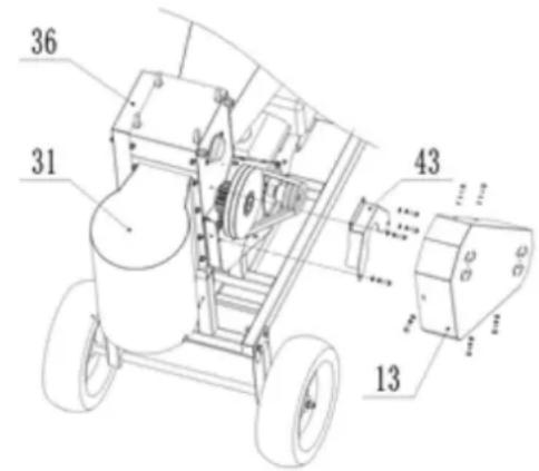
text_image
Technical diagram of a mechanical device with numbered components and labeled partsnatural_image
Blue Hilvert agricultural machine with wheels and a handle (no visible text or symbols)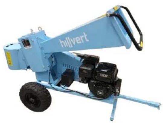
natural_image
Blue hillvert construction machine with visible mechanical components and wheels (no text or symbols on the device itself)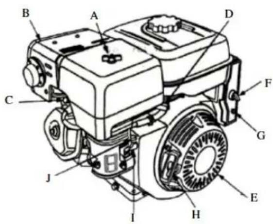
text_image
Technical diagram of a grassy generator with labeled components from A to J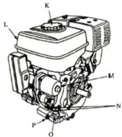
text_image
K L M N P Onatural_image
Collection of various bicycle lifters and equipment including wheel rim, guide rails, and safety gear (no text or symbols visible)HT-WBL-01
natural_image
Product photo of a blue Hilvert motorcycle with green cover, gear, and accessories (no visible text or symbols)HT-WBL-02
text_image
Technical diagram of a mechanical assembly with numbered components and labeled partstext_image
Technical diagram of a wheeled cart with numbered components and dimension annotationstext_image
Technical diagram of a mechanical cart with numbered components and labeled partstext_image
Technical diagram of a mechanical assembly with numbered components and labeled partstext_image
Technical diagram of a vehicle chassis with numbered components and tire placementstext_image
Technical diagram of a mechanical device with numbered components and labeled partstext_image
Diagram of an automotive electrical component with labeled parts A and a battery, showing wiring and grounding.text_image
Technical diagram showing a mechanical component with directional arrows and a labeled inset showing a fish-like object.text_image
Technical diagram showing three labeled components (A, B) of a mechanical assembly with internal parts and directional arrows.natural_image
Mechanical assembly diagram showing engine components and a tool (no text or labels)natural_image
Technical line drawing of a mechanical assembly with no visible text or symbolstext_image
Technical diagram of a mechanical device with labeled parts 31 and 36, showing gears and wheels.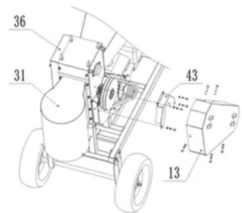
text_image
36 31 43 13natural_image
Blue Hilvert agricultural machine with wheels and control panel (no visible text or symbols)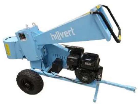
natural_image
Blue hillvert construction machine with visible mechanical components and wheels (no text or symbols on the machine body)
text_image
Technical diagram of a mechanical engine with labeled components from A to J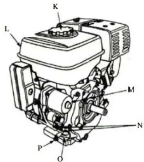
text_image
L K M N P Onatural_image
Collection of outdoor cleaning and repair supplies including blue equipment, wheels, levers, and accessories (no visible text or symbols)HT-WBL-01
natural_image
Assorted blue Hilvert motor components including wheels, sensors, and accessories (no visible text or symbols)HT-WBL-02
text_image
Technical diagram of a mechanical assembly with numbered components and labeled partstext_image
Technical diagram of a wheeled cart with numbered components and dimension annotationstext_image
Technical diagram of a mechanical device with numbered components and labeled partstext_image
Technical diagram of a mechanical assembly with numbered components and labeled partstext_image
Technical diagram of a vehicle chassis with numbered components and tire placementstext_image
Technical diagram of a mechanical device with numbered components, likely an agricultural or industrial machine.text_image
Diagram of an automotive electrical switch with labeled components and wiring connectionstext_image
Technical diagram showing a mechanical assembly with a hand operating a component and a labeled diagram of a tool or device with a mouse.text_image
Technical diagram showing three labeled components (A, B) of a mechanical assembly with internal parts and directional arrows.natural_image
Mechanical assembly diagram showing engine components and a tool (no text or labels)natural_image
Technical line drawing of a mechanical assembly with no visible text or symbolstext_image
Technical diagram of a mechanical assembly with numbered components and labeled partsnatural_image
Blue Hilvert agricultural machine with wheels and control panel (no visible text or symbols)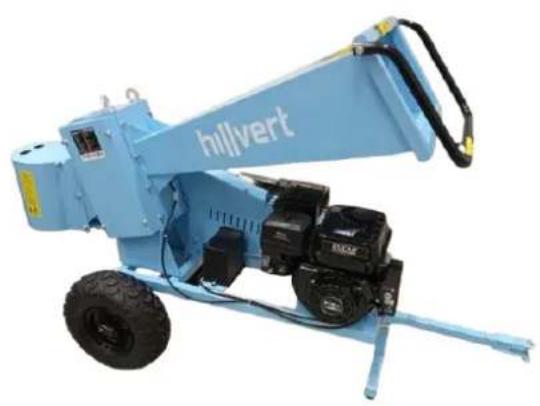
natural_image
Blue hillvert construction machine with visible mechanical components and wheels (no text or symbols on the machine body)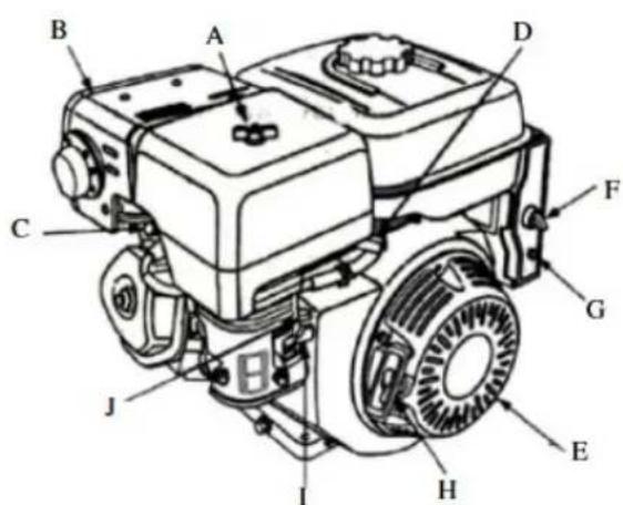
text_image
Technical diagram of a mechanical engine with labeled components from A to J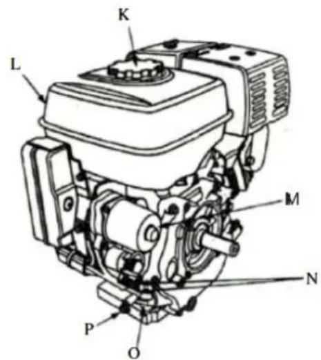
text_image
L K M N P Onatural_image
Collection of mechanical and safety components including blue equipment, wheels, treads, and green bags (no visible text or symbols)HT-WBL-01
natural_image
Collection of outdoor equipment including a blue Hilvert truck, tires, gear, and safety gear (no visible text or symbols)HT-WBL-02
text_image
Technical diagram of a mechanical assembly with numbered components and labeled partstext_image
Technical diagram of a wheeled cart with numbered components and dimension annotationstext_image
Technical diagram of a mechanical device with numbered components and labeled partstext_image
Technical diagram of a mechanical assembly with numbered components and labeled partstext_image
Technical diagram of a vehicle chassis with numbered components and tire placementstext_image
Technical diagram of a mechanical device with numbered components, likely an agricultural or industrial machine.text_image
Diagram of an automotive electrical switch with labeled components and wiring connectionstext_image
Technical diagram showing a mechanical assembly with a tool interacting with a component, alongside a schematic of a device with a mouse and directional arrow.text_image
Technical diagram showing three labeled components (A, B) of a mechanical assembly with internal parts and directional arrows.natural_image
Mechanical assembly diagram showing a valve mechanism with bolts and a base component (no text or labels)natural_image
Technical line drawing of a mechanical assembly with no visible text or symbolstext_image
Technical diagram of a mechanical device with labeled parts 31 and 36, showing gears and wheels.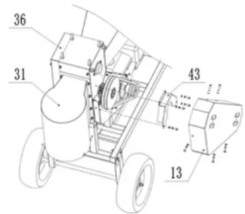
text_image
36 31 43 13natural_image
Blue Hilvert agricultural machine with attached cart and wheels (no visible text or symbols)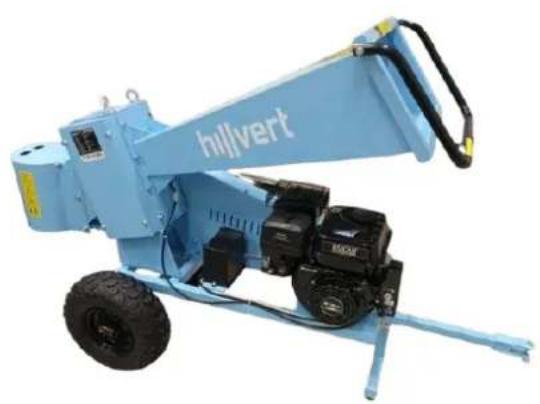
natural_image
Blue hillvert industrial machine with attached motors and wheels (no visible text or symbols)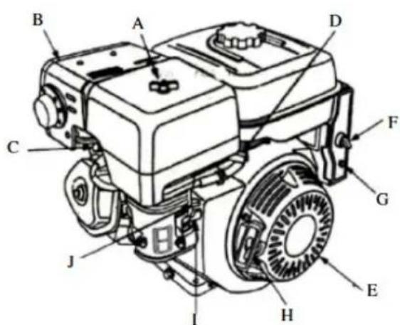
text_image
Technical diagram of a mechanical engine with labeled components from A to J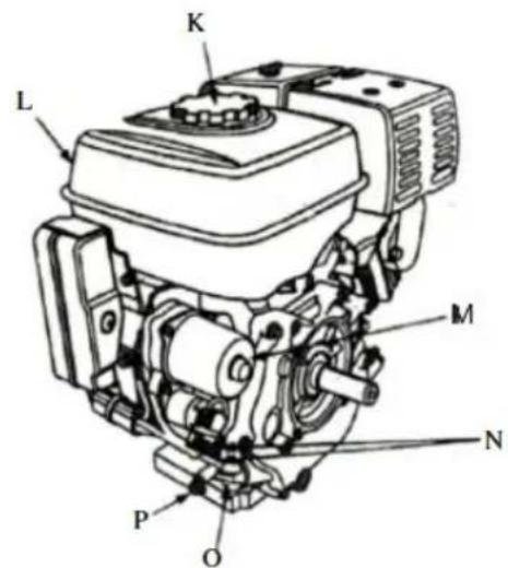
text_image
K L M N P Onatural_image
Collection of various bicycle lifters and equipment including wheelsets, wheels, and safety gear (no text or symbols visible)HT-WBL-01
natural_image
Product photo of a blue Hilvert excavator with green cover, tires, gear, and safety gear (no visible text or symbols)text_image
Technical diagram of a mechanical assembly with numbered components and labeled partstext_image
Technical diagram of a wheeled cart with numbered components and dimension annotationstext_image
Technical diagram of a mechanical device with numbered components and dimension annotationstext_image
Technical diagram of a mechanical assembly with numbered components and labeled partstext_image
Technical diagram of a vehicle chassis with numbered components and tire arrangement labelstext_image
Technical diagram of a mechanical device with numbered components and motion indicatorstext_image
Diagram of an automotive electrical switch with labeled components and wiring connectionstext_image
Technical diagram showing a mechanical assembly with a labeled component and a schematic of a tool interacting with a device.text_image
Technical diagram showing three labeled components (A, B) of a mechanical assembly with parts like a housing, coil, and base.natural_image
Mechanical assembly diagram showing engine components and a tool (no text or labels)natural_image
Technical line drawing of a mechanical assembly with no visible text or symbolstext_image
Technical diagram of a mechanical assembly with numbered components, including gears and wheels, labeled parts 31, 36, and 43.natural_image
Blue industrial machine labeled 'hillvert' with wheels and a handle (no visible text beyond label)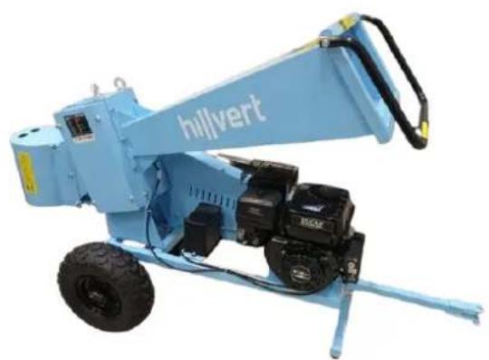
natural_image
Blue hillvert construction machine with visible mechanical components and wheels (no text or symbols on the device itself)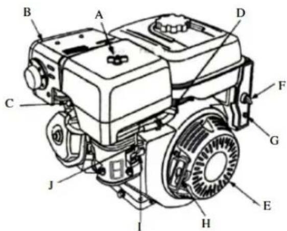
text_image
Technical diagram of a diesel engine with labeled components from A to J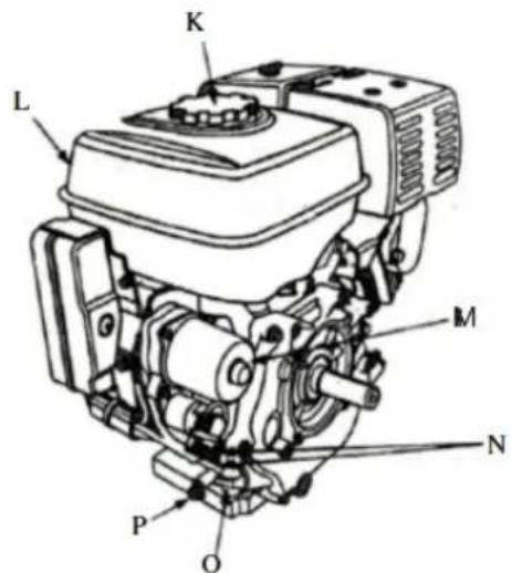
text_image
L K M N P OAPPARATETS PLACERING
natural_image
Collection of outdoor cleaning and equipment including blue tools, wheel rim, tire, and gloves (no visible text or symbols)HT-WBL-01
natural_image
Product photo of a blue Hilvert vehicle with visible wheels, sensors, and accessories (no text or symbols)HT-WBL-02
text_image
Technical diagram of a mechanical assembly with numbered components for identificationtext_image
Technical diagram of a wheeled cart with numbered components and labeled partstext_image
Technical diagram of a mechanical device with numbered components and labeled partstext_image
Technical diagram of a mechanical assembly with numbered components and labeled partstext_image
Technical diagram of a vehicle chassis with numbered components for identificationtext_image
Technical diagram of a mechanical device with numbered components and airflow indicatorstext_image
Technical diagram of an automotive electrical switch with labeled components and wiring3.3. Brug af enhed
3.3.1 Opstart
text_image
Technical diagram showing a mechanical assembly with a labeled component and an inset showing a fish-like structure.natural_image
Mechanical component diagram showing a valve assembly with a curved arrow indicating direction (no text or symbols present)text_image
Technical diagram showing three labeled components (A, B) of a mechanical assembly with directional arrows indicating motion or movement.natural_image
Mechanical assembly diagram showing a valve mechanism with no visible text or symbolsnatural_image
Technical line drawing of a mechanical assembly with no visible text or symbolstext_image
Technical diagram of a mechanical device with labeled parts 31 and 36, showing gears and wheels.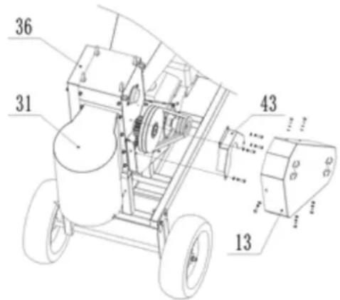
text_image
36 31 43 13natural_image
Blue industrial machine labeled 'hilvert' with wheels and a handle (no visible text beyond label)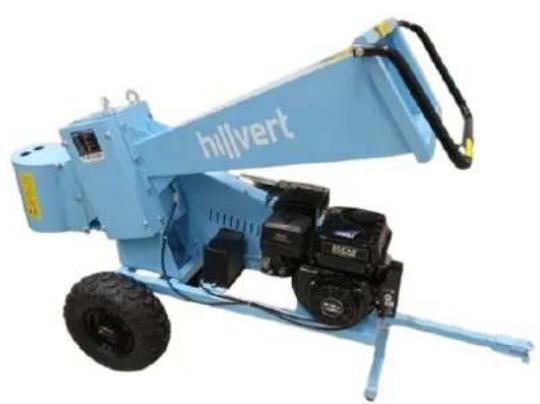
natural_image
Blue hillvert construction machine with attached motors and a handle (no visible text or symbols)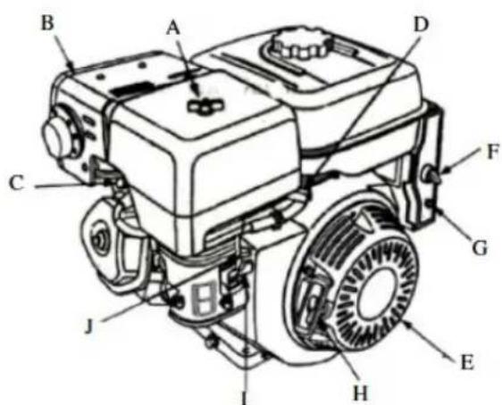
text_image
Technical diagram of a diesel engine with labeled components from A to J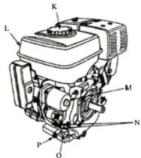
text_image
K L M N P Onatural_image
Collection of blue industrial equipment including wheel stators, lifters, and safety gear (no text or symbols visible)HT-WBL-01
natural_image
Assorted blue and green automotive components including a Hilvert truck, tires, gear, and accessories (no visible text or symbols)HT-WBL-02
text_image
Technical diagram of a mechanical assembly with numbered components, likely a device or enclosure with labeled parts.text_image
Technical diagram of a wheeled cart with numbered components and dimension annotationstext_image
Technical diagram of a mechanical device with numbered components and labeled partstext_image
Technical diagram of a mechanical assembly with numbered components and labeled partstext_image
Technical diagram of a vehicle chassis with numbered components and tire arrangement labelstext_image
Technical diagram of a mechanical device with numbered components and airflow indicatorstext_image
Diagram of an automotive electrical switch with labeled components and wiring connectionstext_image
Technical diagram showing mechanical assembly with labeled parts and a schematic of a device with a mouse and directional arrow.natural_image
Mechanical component diagram showing a valve assembly with a curved arrow indicating direction (no text or symbols present)text_image
Technical diagram showing three labeled components (A, B) of a mechanical assembly with directional arrows indicating motion or movement.natural_image
Mechanical assembly diagram showing a valve mechanism with bolts and a base component (no text or labels)natural_image
Technical line drawing of a mechanical assembly with no visible text or symbolstext_image
Technical diagram of a mechanical device with labeled parts 31 and 36, showing gears and wheels.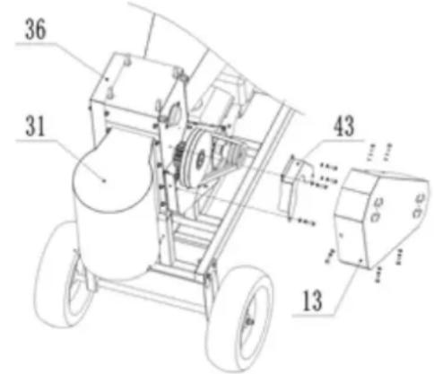
text_image
Technical diagram of a mechanical device with numbered components and labeled partsnatural_image
Blue hillvert agricultural machine with attached cart and wheels (no visible text or symbols)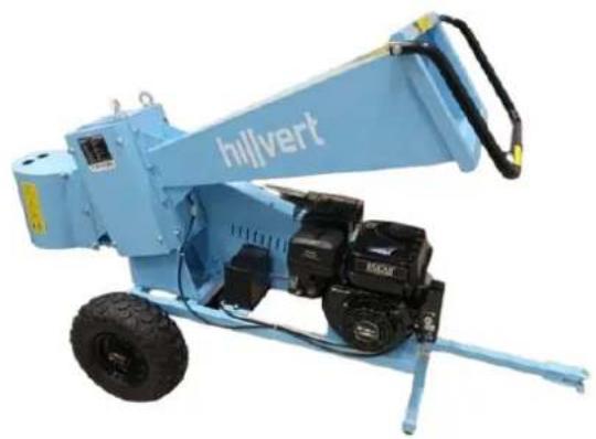
natural_image
Blue Hilvert mining machine with attached mechanical components (no visible text or symbols)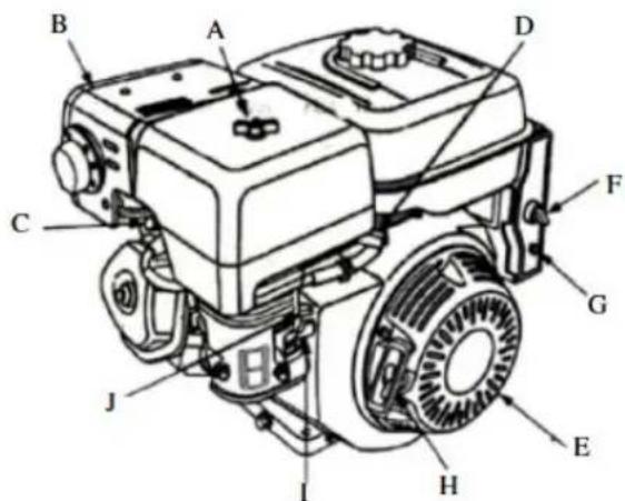
text_image
Technical diagram of a grassy tractor with labeled parts from A to J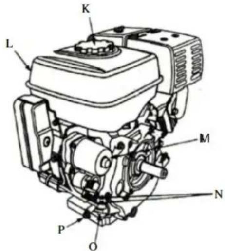
text_image
L K M N P OPLAATS VAN HET APPARAAT
natural_image
Collection of blue industrial equipment including wheel holders, wheels, tarp, and gloves (no visible text or symbols)HT-WBL-01
natural_image
Assorted automotive components including a blue Hilvert truck, tires, gear, and accessories (no visible text or symbols)HT-WBL-02
text_image
Technical diagram of a mechanical assembly with numbered components, likely a device or component layout.text_image
Technical diagram of a wheeled cart with numbered components and dimension annotationstext_image
Technical diagram of a mechanical device with numbered components and labeled partstext_image
Technical diagram of a mechanical assembly with numbered components and labeled partstext_image
Technical diagram of a vehicle chassis with numbered components and labeled partstext_image
Technical diagram of a mechanical device with numbered components and airflow indicatorstext_image
Diagram of an automotive electrical switch with labeled components and wiring connectionstext_image
Technical diagram showing a mechanical assembly with a hand operating a component and a close-up of a device with a labeled arrow pointing to a specific feature.natural_image
Mechanical component diagram showing a valve assembly with a curved arrow indicating direction (no text or symbols present)I) Luchtfilter controleren/vervangen:
text_image
Technical diagram showing three labeled components (A, B) of a mechanical assembly with directional arrows indicating motion or movement.natural_image
Mechanical assembly diagram showing a valve mechanism with no visible text or symbolsnatural_image
Technical line drawing of a mechanical assembly with no visible text or symbolstext_image
Technical diagram of a mechanical assembly with numbered components, including gears and wheelsnatural_image
Blue industrial machine labeled 'hilvert' with wheels and a handle (no visible text beyond label)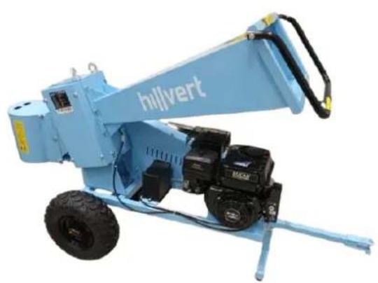
natural_image
Blue hillvert construction machine with attached motors and a handle (no visible text or symbols)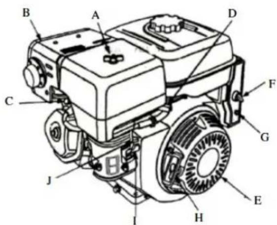
text_image
Technical diagram of a diesel engine with labeled components from A to J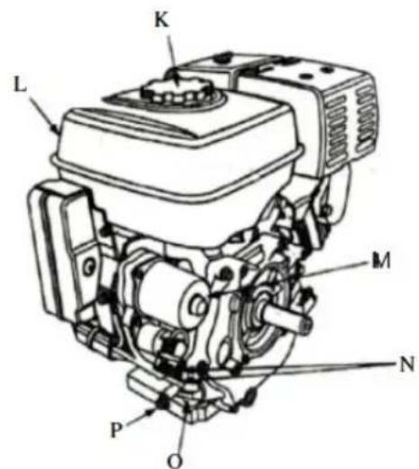
text_image
K L M N P OA. Luftrenser
B. Lyddemper
C. Lyddemperbeskyttelse (valgfritt)
D. Tennplugg
E. Gasspak
F. Tenningsbryter
G. Breaker (elektrisk starttype)
H. Rekylstarterhändtak
I. Choke spak
J. Drivstoffkran
K. Drivstoffpåfyllingslokk
L. Drivstofftank
M. Starter (elektrisk starttype)
N. Motorens identifikasjonsnummer
O. Oljepeilepinne
P. Oljetappeplugg
natural_image
Collection of blue industrial equipment including wheel stators, lifters, and safety gear (no visible text or symbols)HT-WBL-01
natural_image
Assorted blue and green automotive components including a Hilvert truck, tires, gear, and accessories (no visible text or symbols)HT-WBL-02
text_image
Technical diagram of a mechanical assembly with numbered components and labeled partstext_image
Technical diagram of a wheeled cart with numbered components and dimension annotations| Artikkelnummer | Delbeskrivelse |
| 81 | Bolt |
| 78 | Låsemutter |
| 77 | Vaskemaskin |
| 76 | Bolt |
| 51 | Fjærskive |
| 55 | ∅yebolt – for løfting |
| 48 | Fjærskive |
text_image
Technical diagram of a mechanical device with numbered components and labeled parts| Artikkelnummer | Delbeskrivelse |
| 102 | Metalltråd |
| 101 | Bolt |
| 94 | Knott |
| 93 | Tilhengerfeste |
| 70 | Låsemutter |
| 64 | Bolt |
| 52 | Vaskemaskin |
| 51 | Fjærskive |
| 31 | Utløpsbeholder |
text_image
Technical diagram of a mechanical assembly with numbered components and labeled parts| Artikkelnummer | Delbeskrivelse |
| 100 | Låsemutter |
| 99 | Bolt |
| 98 | Batteriledning |
| 97 | Batterideksel |
| 96 | Batteri |
| 1 | Motor |
text_image
Technical diagram of a vehicle chassis with numbered components and tire arrangement labelstext_image
Technical diagram of a mechanical device with numbered components and labeled partstext_image
Diagram of an automotive electrical switch assembly with labeled components A and a battery, showing wiring and grounding.natural_image
Diagram showing a hand operating a mechanical device with a close-up of a device component (no text or symbols present)text_image
Technical diagram showing three labeled components (A, B) of a mechanical assembly with directional arrows indicating movement or force.natural_image
Mechanical assembly diagram showing engine components and a tool (no text or labels)natural_image
Technical line drawing of a mechanical assembly with no visible text or symbolstext_image
Technical diagram of a mechanical assembly with numbered components and directional arrows indicating motion or assembly.natural_image
Blue industrial machine labeled 'hilvert' with wheels and a handle (no visible text beyond label)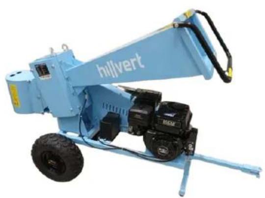
natural_image
Blue hillvert construction machine with attached motors and a handle (no visible text or symbols)
text_image
Technical diagram of a diesel engine with labeled components from A to J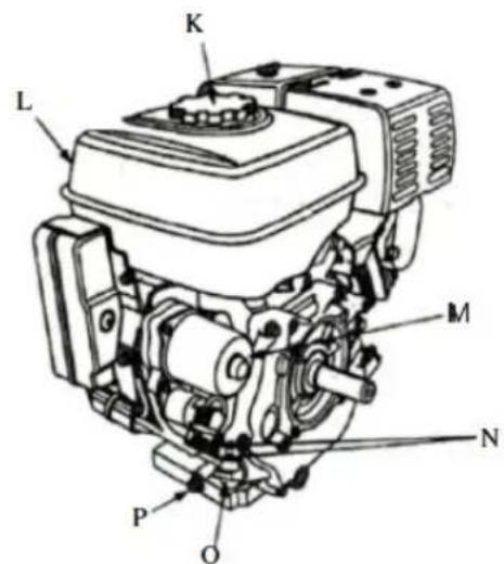
text_image
K L M N P OAPPARATENS PLACERING
natural_image
Collection of blue industrial equipment including wheel stators, lifters, and safety gear (no visible text or symbols)HT-WBL-01
natural_image
Assorted blue and green automotive components including a Hilvert truck, tires, gear, and accessories (no visible text or symbols)HT-WBL-02
text_image
Technical diagram of a mechanical assembly with numbered components, likely for engineering or manufacturing documentation.text_image
Technical diagram of a wheeled cart with numbered components and dimension annotationstext_image
Technical diagram of a mechanical device with numbered components and labeled partstext_image
Technical diagram of a mechanical assembly with numbered components and labeled parts| Nummer på del | Delbeskrivning |
| 100 | Låsmutter |
| 99 | Bult |
| 98 | Batterikabel |
| 97 | Batterilock |
| 96 | Batteri |
| 1 | Motor |
text_image
Technical diagram of a vehicle chassis with numbered components for identificationtext_image
Technical diagram of a mechanical device with numbered components and labeled partstext_image
Diagram of an automotive electrical switch with labeled components and wiring connectionstext_image
Technical diagram showing a mechanical assembly with a hand holding a component and a close-up of a device with a labeled arrow pointing to a specific part.natural_image
Mechanical component diagram showing a valve assembly with a curved arrow indicating direction (no text or symbols present)I) Kontroll/byte av luftfilter:
text_image
Technical diagram showing three labeled components (A, B) of a mechanical assembly with directional arrows indicating motion or movement.natural_image
Mechanical assembly diagram showing a valve mechanism with bolts and a base component (no text or labels)natural_image
Technical line drawing of a mechanical assembly with no visible text or symbolstext_image
Technical diagram of a mechanical device with labeled parts 31 and 36, showing gears and wheels.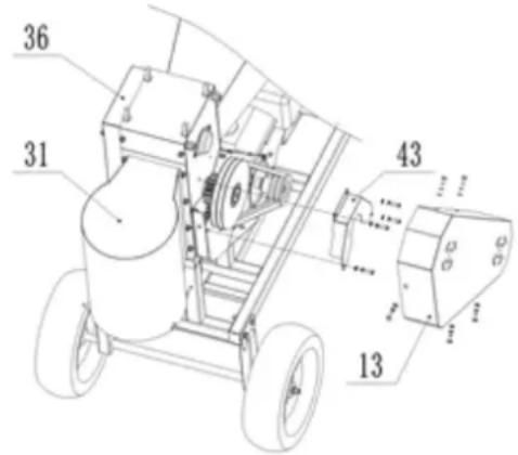
text_image
Technical diagram of a mechanical device with numbered components and dimension annotationsnatural_image
Blue Hilvert agricultural machine with attached cart and wheels (no visible text or symbols)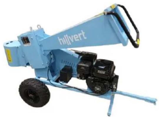
natural_image
Blue hillvert construction machine with attached mechanical components (no visible text or symbols)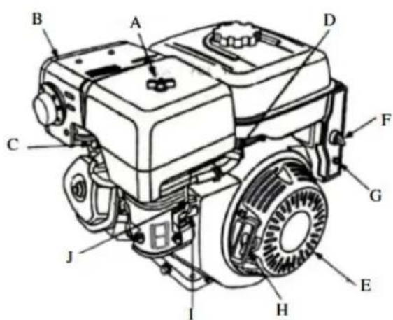
text_image
Technical diagram of a grassy engine with labeled components from A to J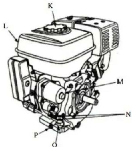
text_image
L K M N P Onatural_image
Collection of outdoor cleaning and repair supplies including blue equipment, wheels, levers, and accessories (no visible text or symbols)HT-WBL-01
natural_image
Assorted blue Hilvert vehicle components including wheels, sensors, and gear (no visible text or symbols)HT-WBL-02
text_image
Technical diagram of a mechanical assembly with numbered components for identificationtext_image
Technical diagram of a wheeled cart with numbered components and dimension annotationstext_image
Technical diagram of a mechanical device with numbered components and labeled partstext_image
Technical diagram of a mechanical assembly with numbered components and labeled partstext_image
Technical diagram of a vehicle chassis with numbered components and tire placementstext_image
Technical diagram of a mechanical device with numbered components and labeled partstext_image
Diagram of an electrical component with labeled parts A and a battery, showing wiring connections and polarity indicators.natural_image
Diagram of a camera lens assembly with a tool interacting with a device, showing a close-up of the lens (no text or symbols present)text_image
Technical diagram showing three labeled components (A, B) of a mechanical assembly with directional arrows indicating motion or movement.natural_image
Mechanical assembly diagram showing a valve mechanism with bolts and a base component (no text or labels)natural_image
Technical line drawing of a mechanical assembly with no visible text or symbolstext_image
Technical diagram of a mechanical device with labeled parts 31 and 36, showing gears and wheels.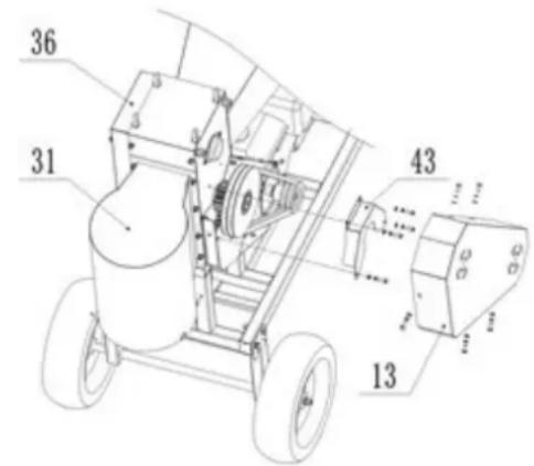
text_image
36 31 43 13natural_image
Blue hillvert agricultural machine with wheels and a handle (no visible text or symbols)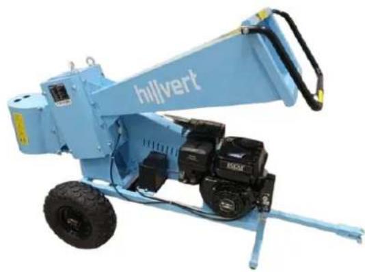
natural_image
Blue hillvert construction machine with visible wheels and mechanical components (no text or symbols)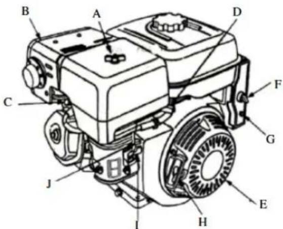
text_image
Technical diagram of a diesel engine with labeled components from A to J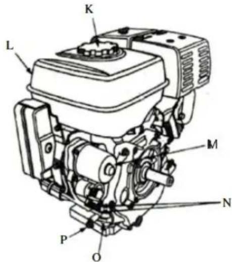
text_image
L K M N P Onatural_image
Collection of outdoor cleaning and equipment including blue tools, wheel rim, tire, and gloves (no visible text or symbols)HT-WBL-01
natural_image
Product photo of a blue Hilvert vehicle with visible wheels, sensors, and accessories (no text or symbols)HT-WBL-02
text_image
Technical diagram of a mechanical assembly with numbered components for identification| Diel č. | Popis dielu |
| 92 | Horný kryt hornej časti násypky |
| 91 | Horná časť násypky |
| 70 | Poistná matica |
| 69 | Bolt |
| 68 | Objímka |
| 67 | Podložka |
| 66 | Bolt |
| 51 | Pružinová podložka |
| 50 | Bolt |
| 11 | jar |
| 10 | Bezpečnostná lišta |
text_image
Technical diagram of a wheeled cart with numbered components and dimension annotationstext_image
Technical diagram of a mechanical device with numbered components and labeled partstext_image
Technical diagram of a mechanical assembly with numbered components and labeled parts| Diel č. | Popis dielu |
| 100 | Poistná matica |
| 99 | Bolt |
| 98 | Kábel batérie |
| 97 | Kryt batérie |
| 96 | Batéria |
| 1 | Motor |
text_image
Technical diagram of a vehicle chassis with numbered components and tire placementsAko hlavné body zdvíhania by ste mali zvolit dve skrutky s okom 88, hlavný rám zdvihnite pomaly do výšky 40-60 cm nad zem pomocou zdvíhacieho zariadenia s nosnosťou nad 300 kg, dbajte na bezpečnost! Namontujte T-tyč 4, tažnú tyč 6, nápravu 7 a kolesá (2 a 3) pomocou D-čapu 51, 52 a skrutky 69 a hardvéru.
B. Zostava násypky
text_image
54 45 55 10 56 53 9 46 55 54Nainštalujte bezpečnostnú tyč 10 na plniaci zásobník 9 pomocou skrutky 53, 54 a hardvéru.
text_image
Technical diagram of a mechanical device with numbered components and airflow indicatorstext_image
Diagram of an automotive electrical switch with labeled components and wiring connectionstext_image
Technical diagram showing a mechanical component with an arrow pointing to a labeled section containing a mouse and fish.natural_image
Mechanical component diagram showing a valve assembly with a curved arrow indicating direction (no text or symbols present)text_image
Technical diagram showing three labeled components (A, B) of a mechanical assembly with directional arrows indicating motion or movement.natural_image
Mechanical assembly diagram showing a valve mechanism with no visible text or symbolsnatural_image
Technical line drawing of a mechanical assembly (no text or symbols)text_image
Technical diagram of a mechanical device with labeled parts 31 and 36, showing gears and wheels.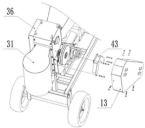
text_image
Technical diagram of a mechanical device with numbered components and dimension annotationsnatural_image
Blue Hilvert agricultural machine with wheels and handle (no visible text or symbols)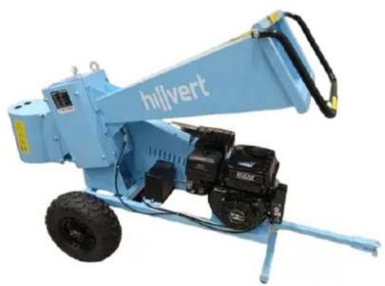
natural_image
Blue Hilvert excavator with attached mechanical components (no visible text or symbols)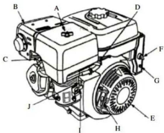
text_image
Technical diagram of a diesel engine with labeled components from A to J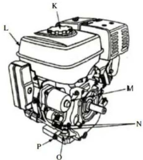
text_image
K L M N P Onatural_image
Collection of blue industrial equipment including wheel casings, levers, and safety gear (no text or symbols visible)HT-WBL-01
natural_image
Product photo of a blue Hilvert utility vehicle with visible wheels, sensors, and safety gear (no text or symbols)HT-WBL-02
text_image
Technical diagram of a mechanical assembly with numbered components, likely a device or component layout.text_image
Technical diagram of a wheeled cart with numbered components and dimension annotationstext_image
Technical diagram of a mechanical cart with labeled components and dimensions, including numbered parts and directional arrows.text_image
Technical diagram of a mechanical assembly with numbered components and labeled partstext_image
Technical diagram of a vehicle chassis with numbered components and tire placementstext_image
Technical diagram of a mechanical device with numbered components and labeled partstext_image
Technical diagram of an automotive electrical switch with labeled components and wiring connectionstext_image
Technical diagram showing a mechanical component with a labeled arrow pointing to a curved path, accompanied by an inset image of a vehicle.text_image
Technical diagram showing three labeled components (A, B) of a mechanical device with internal parts and assembly details.natural_image
Mechanical assembly diagram showing engine components and a tool (no text or labels)natural_image
Technical line drawing of a mechanical assembly with no visible text or symbolstext_image
Technical diagram of a mechanical assembly with numbered components and labeled partsnatural_image
Blue industrial machine labeled 'hillvert' with wheels and handle (no visible text beyond branding)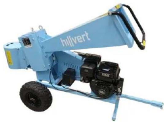
natural_image
Blue hillvert construction machine with visible wheels and mechanical components (no text or symbols)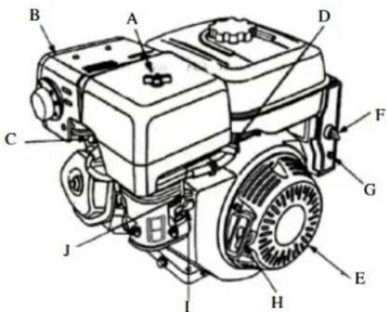
text_image
Technical diagram of a diesel engine with labeled components from A to J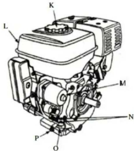
text_image
L K M N P Onatural_image
Collection of various bicycle lifters and equipment including wheelsets, guide rails, and safety gear (no text or symbols visible)HT-WBL-01
natural_image
Collection of outdoor equipment including a blue Hilvert truck, tire tractors, and accessories (no visible text or symbols)HT-WBL-02
text_image
Technical diagram of a mechanical assembly with numbered components and dimension annotationstext_image
Technical diagram of a wheeled cart with numbered components and dimension annotationstext_image
Technical diagram of a mechanical device with numbered components and dimension annotationstext_image
Technical diagram of a mechanical assembly with numbered components and labeled partstext_image
Technical diagram of a vehicle chassis with numbered components and tire placementstext_image
Technical diagram of a mechanical device with numbered components and labeled partstext_image
Diagram of an automotive electrical switch with labeled components and wiring connections3.3. Χρήση συσκευής
3.3.1 Εκκίνηση
text_image
Technical diagram showing a mechanical component with directional arrows and a labeled schematic element.text_image
Technical diagram showing three views of a mechanical device with labeled parts A and Bnatural_image
Mechanical assembly diagram showing engine components and a tool (no text or labels)natural_image
Technical line drawing of a mechanical assembly with no visible text or symbolstext_image
Technical diagram of a mechanical assembly with numbered components and directional arrows indicating motion or assembly.natural_image
Blue industrial machine labeled 'hilvert' with wheels and a handle (no visible text beyond label)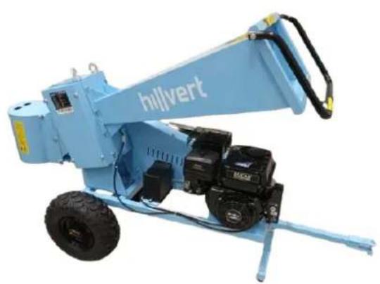
natural_image
Blue hillvert construction machine with attached motors and a handle (no visible text or symbols)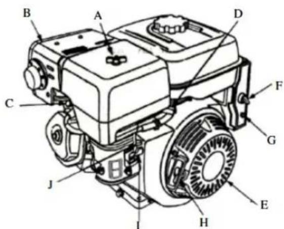
text_image
Technical diagram of a diesel engine with labeled components from A to J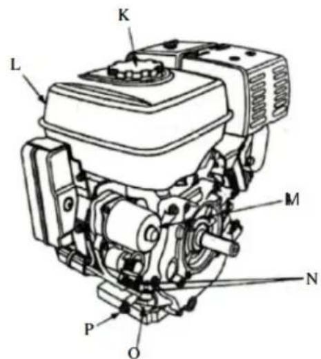
text_image
K L M N P Onatural_image
Collection of blue industrial equipment including wheel stators, lifters, and safety gear (no text or symbols visible)HT-WBL-01
natural_image
Assorted blue and green automotive components including a Hilvert truck, tires, gear, and accessories (no visible text or symbols)HT-WBL-02
text_image
Technical diagram of a mechanical assembly with numbered components, likely a device or component layout.| Broj dijela | Opis dijela |
| 92 | Gornji poklopac za gornji dio spremnika za hranu |
| 91 | Gornji dio spremnika za hranu |
| 70 | Sigurnosna matica |
| 69 | Vijak |
| 68 | Čahura |
| 67 | Perilica |
| 66 | Vijak |
| 51 | Opruga za pranje |
| 50 | Vijak |
| 11 | Proljeće |
| 10 | Sigurnosna šipka |
Najprije instalirajte sigurnosnu polugu 10 kao što je prikazano na slici pomoću hardvera i opruge da je pričvrstite na gornji dio spremnika za hranu 91. Zatim postavite gornji poklopac za gornji dio spremnika za hranu 92 na gornji dio spremnika za hranu 91 pomoću vijka 50, i pričekajte sljedeći korak instalacije.
B. Sklop prednjih kotača
text_image
4 90 89 3text_image
Technical diagram of a wheeled cart with numbered components and dimension annotations| Broj dijela | Opis dijela |
| 81 | Vijak |
| 78 | Sigurnosna matica |
| 77 | Perilica |
| 76 | Vijak |
| 51 | Opruga za pranje |
| 55 | Očni vijak – za podizanje |
| 48 | Opruga za pranje |
Najmanje dva prstenasta vijka 55 treba odabrati kao glavne točke podizanja, polako podižite glavni okvir 8 na visinu od 50-70 cm iznad tla s uređajem za podizanje s kapacitetom podizanja od preko 1000 kg, pazeći na sigurnost. Kao što je prikazano na gornjoj slici, prednji kotači i okvir stražnjeg kotača mogu se pričvrstiti na glavni okvir 8 hardverom.
text_image
Technical diagram of a mechanical cart with numbered components and dimension annotations| Broj dijela | Opis dijela |
| 102 | Žica |
| 101 | Vijak |
| 94 | gumb |
| 93 | Kuka za vuču |
| 70 | Sigurnosna matica |
| 64 | Vijak |
| 52 | Perilica |
| 51 | Opruga za pranje |
| 31 | Izlazni lijevak |
Pričvrstite gotov gornji dio spremnika za punjenje 91 i izlaznog spremnika 31 na glavni okvir pomoću hardvera; Spojite žicu 102 na upravljačku žicu motora, izvucite lijevu iglu na sigurnosnom prekidaču na sigurnosnoj šipki 10. Pričvrstite polugu za vuču 93 pomoću gumba 94 na okviru.
F. Sastavljanje i spajanje baterije
text_image
Technical diagram of a mechanical assembly with numbered components and labeled parts| Broj dijela | Opis dijela |
| 100 | Sigurnosna matica |
| 99 | Vijak |
| 98 | Žica za bateriju |
| 97 | Poklopac baterije |
| 96 | Baterija |
| 1 | Motor |
Spojite pozitivne i negativne žice baterije 98 na pozitivne i negativne polove baterije 96, s pozitivnim polom spojenim na pozitivni pol, a negativnim polom s negativnim polom. Nemojte ih spajati nepravilno, inače će oštetiti bateriju i motor. Pričvrstite poklopac baterije 97 na bateriju 96 i pričvrstite ih na okvir vijkom 99.
HT-WBL-02
A. Sastavljanje okvira
text_image
Technical diagram of a vehicle chassis with numbered components and tire placementsDva prstenasta vijka 88 treba odabrati kao glavne točke podizanja, polako podižite glavni okvir na visinu od 40-60 cm iznad tla pomoću uređaja za podizanje s kapacitetom podizanja od preko 300 kg, pazeći na sigurnost! Ugradite T-polu 4, polugu za vuču 6, osovinu 7 i kotače (2 i 3) pomoću D-pina 51, 52 i vijka 69 i hardvera.
B. Sklop spremnika za hranu
text_image
54 45 55 10 56 53 9 46 55 54Ugradite sigurnosnu šipku 10 na spremnik za punjenje 9 pomoću vijaka 53,54 i okova.
text_image
Technical diagram of a mechanical device with numbered components and airflow indicatorsUgradite spremnik za punjenje 9 i izlazni lijevak 31 pomoću vijaka i hardvera. Spojite sigurnosne žice 87 s motorom, izvucite zatik za ponovno postavljanje na prekidaču (lijeva strana na prekidaču) za početak.
PUNJENJE MOTORNOG ULJA
text_image
Diagram of an automotive electrical switch with labeled components and wiring connections3.3. Upotreba uređaja
3.3.1 Pokretanje
- Postavite ventil za gorivo - ikona razdjelnika - u otvoreni položaj ("ON" - pogledajte piktogram potpisa na kućištu filtra za zrak) tako da gorivo može teći iz spremnika u rasplinjač za pokretanje motora.
text_image
CHOKE ↔ RUN OFF ↔ ON- Samo kada je motor hladan : aktivirajte čok, tj. postavite ručicu ručnog usisavanja u zatvoreni položaj ("ČOK") - pogledajte univerzalnu ikonu.
- Namjestite ručicu gasa - kontrolu broja okretaja motora - na pribl. 1/2 mjerila u smjeru brze vrtnje. NAPOMENA: ikona zeca simbolizira brzu rotaciju, a kornjača je za male brzine, tako da pomicanjem ručice prema odgovarajućoi ikoni povećavate ili smanjuiete brzinu motora.
text_image
Technical diagram showing mechanical assembly with labeled components and a schematic of a tool path with directional arrows.- Okrenite ključ za paljenje (ključ) na motoru iz položaja "ISKLJUČENO" u položaj "UKLJUČENO" (samo HT-WBL-01), a zatim u položaj "START" (ili ikonu ručice) tako da se motor može pokrenuti - nakon pokretanja, odmah otpustite ključ za paljenje.
natural_image
Mechanical component diagram showing a valve assembly with a curved arrow indicating direction (no text or symbols present)text_image
Technical diagram showing three labeled components (A, B) of a mechanical assembly with directional arrows indicating motion or movement.- Uklonite vanjski poklopac pročistača zraka (A). Pazite da spriječite da prljavština i krhotine upadnu u sklop pročistača zraka.
- Odvojite filtar za zrak (A) od kućišta filtra za zrak (B).
- Pregledajte filtar zraka. Očistite prljavi filter zraka toplom vodom i blagim sapunom. Ostavite filtar za zrak da se temeljito osuši prije ponovnog postavljanja.
- Ugradite sklop filtra za zrak na rasplinjač i pričvrstite ga vijkom.
- Napomena: Nemojte koristiti zrak pod pritiskom ili otapala za čišćenje filtera. Zrak pod tlakom može oštetiti filtar, a otapala će ga otopiti.
m) Zamjena motornog ulja:
natural_image
Mechanical assembly diagram showing a valve mechanism with attached components and a base plate (no text or labels)natural_image
Technical line drawing of a mechanical assembly with no visible text or symbolstext_image
Technical diagram of a mechanical device with labeled parts 31 and 36, showing gears and wheels.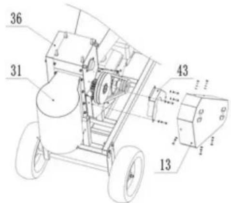
text_image
36 31 43 13- [HT-WBL-02] otvorite poklopac mjenjača 36 uklanjanjem 4x vijka koji ga drže b77. Podmažite svaku komponentu zupčanika; Provjerite fleksibilnu rotaciju i istrošenost ključnih dijelova kao što su ležajevi, oštrice, remeni itd. Ako se pronađu nedostaci, potrebno ih je odmah popraviti prije ponovne obrade. Posebice za oštrice potrebne su redovite kontrole, a popravci oštrica obavljaju se u stručnim ustanovama. Tupa oštrica može smanjiti učinkovitost stroja, au teškim slučajevima može oštetiti komponente stroja.
SIGURNO VAĐENJE BATERIJA
U uređaje su ugrađene baterije GEL 12V 9Ah.
Uklonite iskorištenu bateriju iz uređaja istim postupkom kojim ste ih instalirali.
natural_image
Blue industrial machine labeled 'hilvert' with wheels and a handle (no visible text beyond label)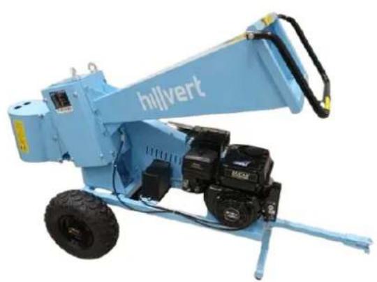
natural_image
Blue hillvert construction machine with attached motors and a handle (no visible text or symbols)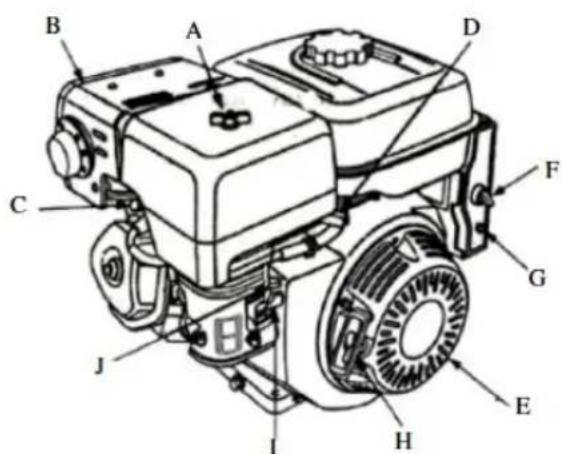
text_image
Technical diagram of a grassing machine with labeled components from A to J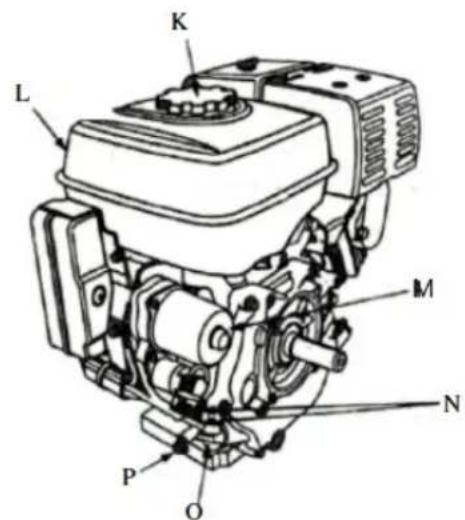
text_image
K L M N P OA. Oro valytuvas
B. Duslintuvas
C. Duslintuvo apsauga (neprivaloma)
D. Uždegimo žvakė
E. Droselio svirtis
F. Uždegimo jungiklis
G. Pertraukiklis (elektrinio starterio tipo)
H. Atatrankos starterio rankena
natural_image
Collection of various bicycle lifters and equipment including wheelsets, wheels, and safety gear (no text or symbols visible)HT-WBL-01
natural_image
Assorted blue and green automotive components including a Hilvert truck, tires, gear, and accessories (no visible text or symbols)HT-WBL-02
text_image
Technical diagram of a mechanical assembly with numbered components and labeled partstext_image
Technical diagram of a wheeled cart with numbered components and dimension annotationstext_image
Technical diagram of a mechanical device with numbered components and labeled partstext_image
Technical diagram of a mechanical assembly with numbered components and labeled partstext_image
Technical diagram of a vehicle chassis with numbered components and tire arrangement labelstext_image
Technical diagram of a mechanical device with numbered components, likely an agricultural or industrial machine.text_image
Diagram of an electrical circuit with labeled components including battery and switch, marked with positive and negative terminals.text_image
Technical diagram showing a mechanical assembly with a hand operating a tool and a labeled component with directional arrows.text_image
Technical diagram showing three labeled components (A, B) of a mechanical assembly with internal parts and directional arrows.natural_image
Mechanical assembly diagram showing engine components and a tool (no text or labels)natural_image
Technical line drawing of a mechanical assembly with no visible text or symbolstext_image
Technical diagram of a mechanical assembly with numbered components and directional arrows indicating motion or assembly.natural_image
Blue hillvert agricultural machine with wheels and control panel (no visible text or symbols)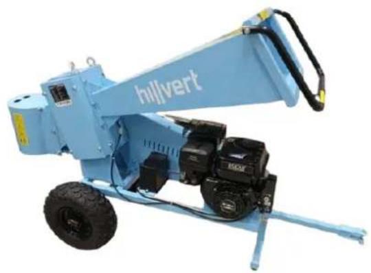
natural_image
Blue Hilvert mining machine with attached motors and wheels (no visible text or symbols)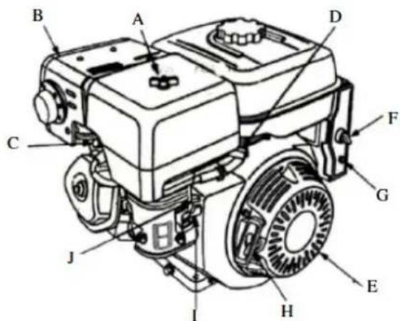
text_image
Technical diagram of a grassy tractor with labeled parts from A to J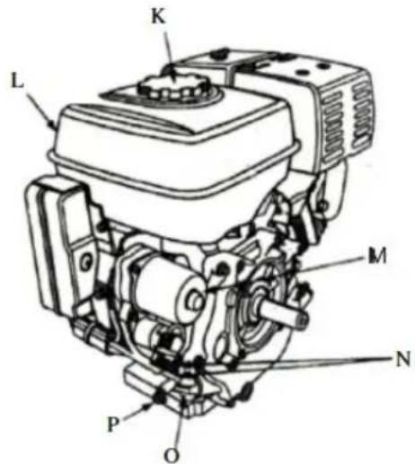
text_image
L K M N P OA. Filtru de aer
B. Toba de esapament
C. Protectie toba de esapament (optional)
D. Bujie
E. Maneta de acceleratie
F. Comutator de aprindere
G. Întrerupător (tip demaror electric)
H. Mâner demaror cu recul
natural_image
Collection of blue industrial equipment including wheel stators, lifters, and safety gear (no text or symbols visible)HT-WBL-01
natural_image
Collection of outdoor equipment including a blue Hilvert truck, tire, sensors, and safety gear (no visible text or symbols)HT-WBL-02
text_image
Technical diagram of a mechanical assembly with numbered components for identificationtext_image
Technical diagram of a wheeled cart with numbered components and dimension annotationstext_image
Technical diagram of a mechanical device with numbered components and labeled partstext_image
Technical diagram of a mechanical assembly with numbered components and labeled partstext_image
Technical diagram of a vehicle chassis with numbered components for identificationtext_image
Technical diagram of a mechanical device with numbered components, likely an agricultural or industrial machine.text_image
Diagram of an automotive electrical switch with labeled components A and a battery, showing wiring connections.text_image
Technical diagram showing a mechanical assembly with a hand operating a component and a close-up of a device with a labeled arrow pointing to a specific feature.text_image
Technical diagram showing three labeled components (A, B) of a mechanical assembly with internal parts and directional arrows.natural_image
Mechanical assembly diagram showing engine components and a tool (no text or labels)natural_image
Technical line drawing of a mechanical assembly with no visible text or symbolstext_image
Technical diagram of a mechanical assembly with numbered components, including gears and wheels, labeled parts 31, 36, and 43.natural_image
Blue industrial machine labeled 'hilvert' with wheels and a handle (no visible text beyond label)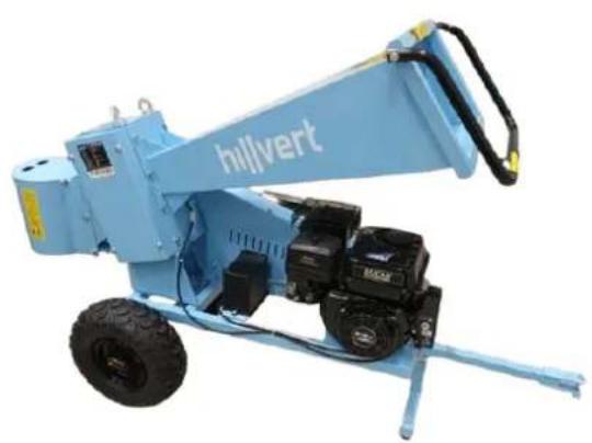
natural_image
Blue hillvert construction machine with attached motors and a handle (no visible text or symbols)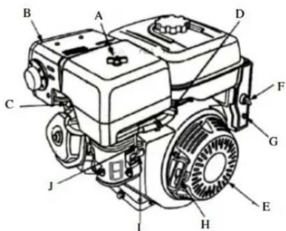
text_image
Technical diagram of a diesel engine with labeled components from A to J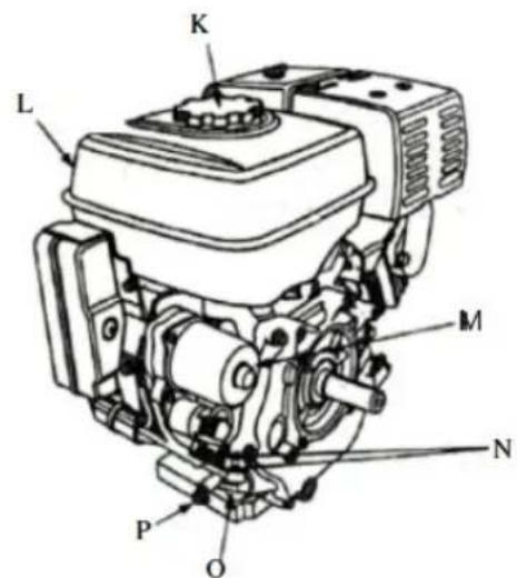
text_image
K L M N P Onatural_image
Collection of blue industrial equipment including wheel casings, levers, and safety gear (no text or symbols visible)HT-WBL-01
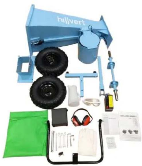
natural_image
Assorted blue Hilvert vehicle components including tires, gear, and accessories (no visible text or symbols)HT-WBL-02
POZOR: med namestitvijo ne postavljajte rok ali drugih delov telesa v radij rotorja z rezili; Ne dotikajte se rezil z rokami ali drugimi deli telesa.
HT-WBL-01
text_image
Technical diagram of a mechanical assembly with numbered components, likely a device or component layout.| Številka dela | Opis dela |
| 92 | Zgornji pokrov za zgornji del hranilnika |
| 91 | Zgornji del hranilnika |
| 70 | Protimatica |
| 69 | Vijak |
| 68 | Puša |
| 67 | Pralni stroj |
| 66 | Vijak |
| 51 | Vzmetna podložka |
| 50 | Vijak |
| 11 | Pomlad |
| 10 | Varnostna palica |
text_image
Technical diagram of a wheeled cart with numbered components and labeled partstext_image
Technical diagram of a mechanical device with numbered components and labeled partstext_image
Technical diagram of a mechanical assembly with numbered components and labeled parts| Številka dela | Opis dela |
| 100 | Protimatica |
| 99 | Vijak |
| 98 | Akumulatorska žica |
| 97 | Pokrov baterije |
| 96 | Baterija |
| 1 | Motor |
Povežite pozitivno in negativno žico akumulatorske žice 98 s pozitivnim in negativnim polom baterije 96, tako da je pozitivni pol povezan s pozitivnim polom, negativni pol pa z negativnim polom. Ne priključite jih nepravilno, sicer lahko poškodujete baterijo in motor. Pritrdite pokrov baterije 97 na baterijo 96 in ju pritrdite na okvir z vijakom 99.
HT-WBL-02
A. Montaža okvirja
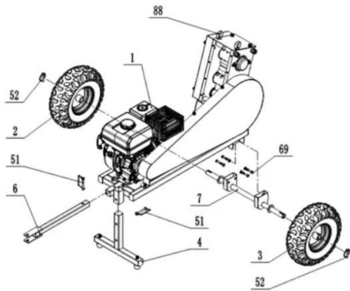
text_image
Technical diagram of a vehicle chassis with numbered components for identificationtext_image
Technical diagram of a mechanical device with numbered components and airflow indicatorstext_image
Diagram of an automotive electrical switch with labeled components and wiring connections3.3. Uporaba naprave
3.3.1 Zagon
text_image
Technical diagram showing a mechanical assembly with a labeled component and a schematic of a tool or device with directional arrows.- Obrnite ključ za vžig (ključ) na motorju iz položaja "OFF" v položaj "ON" (samo HT-WBL-01) in nato v položaj "START" (ali ikona gonilke), da se motor lahko zažene – po zagonu, takoj spustite ključ za vžig.
natural_image
Mechanical component diagram showing a propeller and valve assembly (no text or symbols)text_image
Technical diagram showing three labeled components (A, B) of a mechanical assembly with directional arrows indicating motion or movement.natural_image
Mechanical assembly diagram showing a valve mechanism with bolts and a base component (no text or labels)natural_image
Technical line drawing of a mechanical assembly with no visible text or symbolstext_image
Technical diagram of a mechanical device with labeled parts 31 and 36, showing gears and wheels.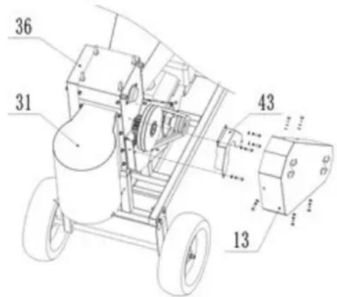
text_image
36 31 43 13For the disposal of the device please consider and act according to the national and local rules and regulations.
CONTACT
expondo Polska sp. z o.o. sp. k.