HT-WT-750L - Water tank Hillvert - Free user manual and instructions
Find the device manual for free HT-WT-750L Hillvert in PDF.


User questions about HT-WT-750L Hillvert
0 question about this device. Answer the ones you know or ask your own.
Ask a new question about this device
Download the instructions for your Water tank in PDF format for free! Find your manual HT-WT-750L - Hillvert and take your electronic device back in hand. On this page are published all the documents necessary for the use of your device. HT-WT-750L by Hillvert.
USER MANUAL HT-WT-750L Hillvert
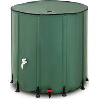
COLLAPSIBLE WATER TANK
BEDIENUNGSANLEITUNG
USER MANUAL
INSTRUKCJA OBSŁUGI
NÁVOD K POUŽITÍ
MANUEL D'UTILISATION
ISTRUZIONI PER L'USO
text_image
Technical diagram of a cylindrical device with numbered components labeled 3 through 9natural_image
Simple line drawing of a cylindrical object with a separate arrow pointing to it, no text or symbols present.This User Manual has been translated for your convenience using machine translation. Reasonable efforts have been made to provide an accurate translation; however, no automated translation is perfect nor is it intended to replace human translators. The official User Manual is the English version. Any discrepancies or differences created in the translation are not binding and have no legal effect for compliance or enforcement purposes. If any questions arise related to the accuracy of the information contained in the User Manual, please refer to the English version of those contents which is the official version.
Technical data
| Parameter description | Parameter value | |||
| Product name | COLLAPSIBLE WATER TANK | |||
| Model | HT-WT-200L | HT-WT-380L | HT-WT-500L | HT-WT-750L |
| Outlet valve diameter | 3/4'' | |||
| Diameter of support rods[mm] | Φ20 | |||
| Capacity [l] | 200 | 380 | 500 | 750 |
| Dimensions [Width x Depth x Height; cm] | 60x60x70 | 70x70x99 | 80x80x99 | 100x100x99 |
| Weight [kg] | 2.15 | 6.5 | 4.1 | 5.8 |
Product description
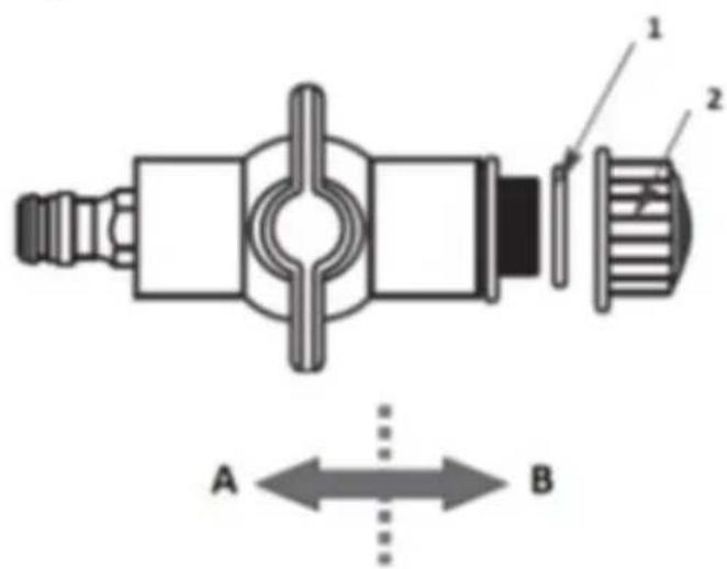
Tap
text_image
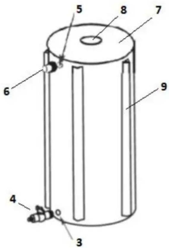
Technical diagram of a mechanical component with labeled parts and directional arrows indicating movement or force.Tank
text_image
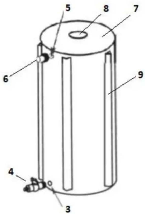
Technical diagram of a cylindrical device with numbered components labeled 3 through 9A. Outer part
B. Inner part
1. Gasket
2. Cap
3. Hole for Tap
4. Tap
5. Spigot hole
6. Spigot
7. Top flap
8. Filter opening
9. Tunnels for poles
Installation of the unit
- Tap assembly:
a) From the tap unscrew the cap (2) and remove the gasket (1).
b) Put the inner (B) part of the tap through the hole (3) in the bottom of the tank.
c) Put the gasket (1) on the inner part of the tap and carefully tighten the cap (2).
- Installation of the overflow spigot:
a) From the spigot unscrew the cap.
b) Pass the inner part of the spigot through the hole (4) in the top of the tank.
c) Thoroughly tighten the cap.
- Installation of construction poles:
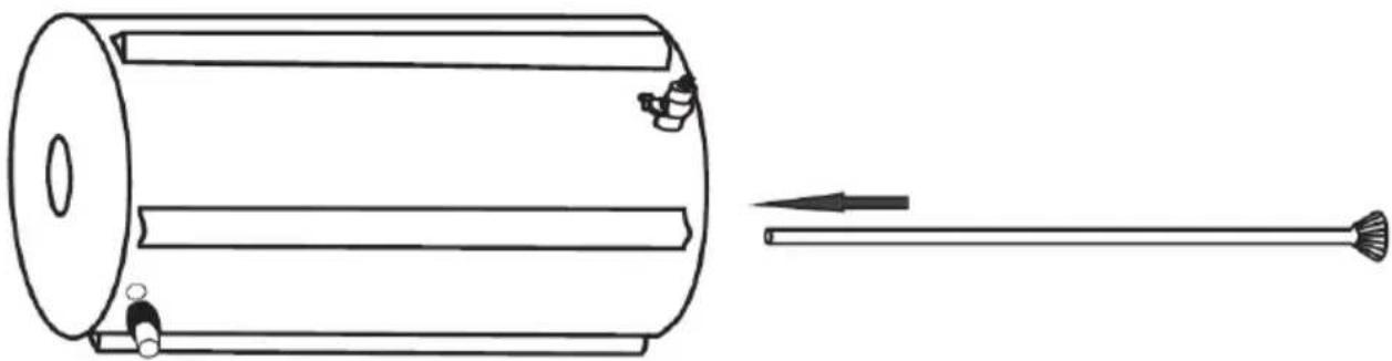
natural_image
Simple line drawing of a cylindrical object with a flanged end and a separate arrow pointing to it (no text or symbols)Unfold the tank on the ground and slide the poles into the tunnels located on the outside of the tank. The poles should be inserted from the bottom so that the ends secured with feet remain outside.
- Setting up and securing the tank
The ground must be level, stable, without sharp objects and stones. To protect the bottom, setting the tank, for example, on foil or agrofabric is recommended.
Set the finished product on such a prepared surface and then check that the tap and the top flap are closed.
Cleaning and storage of the tank
A) Regularly check whether the water collection and filtering hole located in the top flap of the tank has not been clogged by, for example, leaves.
B) Clean the tank regularly with a soft brush to avoid slippery deposits. Do not use sharp objects for cleaning as they may damage the tank.
C) Before folding and storing the product, the tank should be completely emptied and allowed to dry. Do not fold a wet product!
D) Store the product in a dry and cool place protected from moisture and direct sunlight.

text_image
Technical diagram of a cylindrical device with numbered components labeled 3 through 9natural_image
Simple line drawing of a cylindrical object with a separate rod extending outward (no text or symbols)text_image
Technical diagram of a cylindrical device with numbered components labeled 3 through 9natural_image
Simple line drawing of a cylindrical object with a pin and a separate rod extending outward (no text or symbols)text_image
Technical diagram of a mechanical component with labeled parts and directional arrows indicating movement or flow.Réservoir
text_image
Technical diagram of a cylindrical device with numbered components labeled 3 through 9natural_image
Simple line drawing of a cylindrical object with a flanged end and a separate arrow pointing to it (no text or symbols)text_image
Technical diagram of a mechanical component with labeled parts and directional arrows indicating movement or assembly.Contenitore
text_image
Technical diagram of a cylindrical device with numbered components labeled 3 through 9natural_image
Line drawing of a cylindrical object with a flanged end and a separate rod with an arrow indicating direction (no text or symbols)text_image
Technical diagram of a mechanical component with labeled parts and directional arrows indicating movement or force.Depósito

text_image
Technical diagram of a cylindrical device with numbered components labeled 3 through 9natural_image
Simple line drawing of a cylindrical object with a flanged end and a separate arrow pointing to it (no text or symbols)text_image
Technical diagram of a cylindrical device with numbered components labeled 3 through 9natural_image
Simple line drawing of a cylindrical object with a shaft and two protruding rods, no text or symbols present.text_image
Technical diagram of a cylindrical device with numbered components labeled 3 through 9natural_image
Simple line drawing of a cylindrical object with a flanged end and a separate arrow pointing to it (no text or symbols)OUR CUSTOMERS' SATISFACTION IS OUR MAIN GOAL! PLEASE CONTACT US WITH QUESTIONS AT:
NASZYM GŁÓWNYM CELEM JEST SATYSFAKCJA KLIENTÓW W PRZYPADKU PYTAŃ PROSIMY O KONTAKT Z PRZEDSTAWICIELEM W DANYM KRAJU:
NAŠÍM HLAVNÍM CÍLEM JE SPOKOJENOST NAŠICH ZÁKAZNÍKŮ! V PŘÍPADĚ OTÁZEK NÁS PROSÍM KONTAKTUJTE NA:
NOTRE BUT PREMIER EST VOTRE SATISFACTION! POUR TOUTE QUESTION, CONTACTEZ NOUS SUR: