HT-MIEX_01 - Construction Equipment Hillvert - Free user manual and instructions
Find the device manual for free HT-MIEX_01 Hillvert in PDF.


User questions about HT-MIEX_01 Hillvert
0 question about this device. Answer the ones you know or ask your own.
Ask a new question about this device
Download the instructions for your Construction Equipment in PDF format for free! Find your manual HT-MIEX_01 - Hillvert and take your electronic device back in hand. On this page are published all the documents necessary for the use of your device. HT-MIEX_01 by Hillvert.
USER MANUAL HT-MIEX_01 Hillvert
natural_image
Three black-and-white icons representing speaker, hourglass, and battery symbols (no text or labels)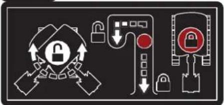
flowchart
graph TD
    A["Lock"] --> B["Switch"]
    B --> C["Lock"]
    C --> D["Switch"]
    D --> E["Lock"]
    E --> F["Switch"]
    F --> G["Lock"]
    G --> H["Switch"]
    H --> I["Lock"]
    I --> J["Switch"]
    J --> K["Lock"]
    K --> L["Switch"]
    L --> M["Lock"]
    M --> N["Switch"]
    N --> O["Lock"]
    O --> P["Switch"]
    P --> Q["Lock"]
    Q --> R["Switch"]
    R --> S["Lock"]
    S --> T["Switch"]
    T --> U["Lock"]
    U --> V["Switch"]
    V --> W["Lock"]
    W --> X["Switch"]
    X --> Y["Lock"]
text_image
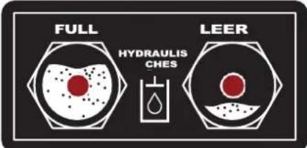
FULL HYDRAULIS CHES LEER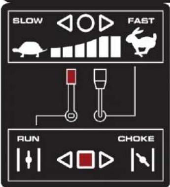
text_image
SLOW FAST RUN CHOKE
text_image
POWER OUTLET 12V~ 15A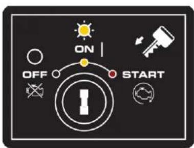
text_image
ON OFF STARTHorn Position
Stunden
Energie-Anzeige
natural_image
Three mechanical robotic arms in a row, no text or symbols visiblenatural_image
Illustration of a hand holding a magnifying glass over a document with a computer icon, symbolizing technology or data analysis (no text present)Manuelles Rohr
text_image
DANGERtext_image
Diagram illustrating three scenarios of construction or vehicle collision, showing workers on a truck, excavators, and a crane with a load symbol.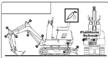
text_image
Plattform Schauknatural_image
Line drawing of an excavator on a power line with visible impact waves (no text or symbols)natural_image
Technical line drawing of an excavator on a sloped terrain (no text or symbols)natural_image
Technical line drawing of an excavator with tracked base and support structure (no text or symbols)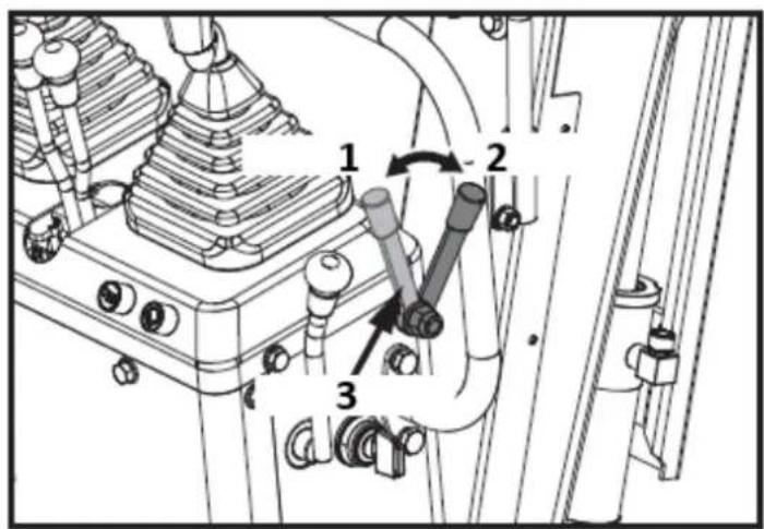
text_image
Technical diagram of a mechanical assembly with numbered components and directional arrows indicating motion or movement.text_image
Technical diagram of a mechanical assembly with numbered components and directional arrows indicating motion or flow.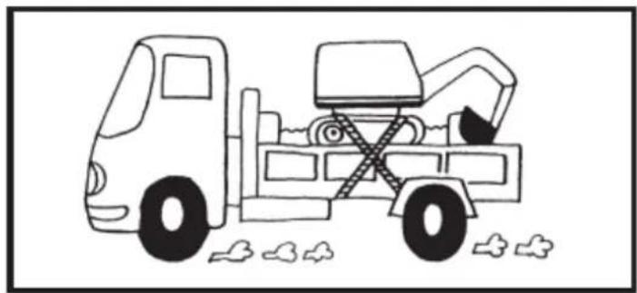
natural_image
Line drawing of a dump truck with an excavator and pile debris (no text or symbols)natural_image
Diagram of a hand holding a tool with motion arrows indicating movement (no text or symbols)natural_image
Silhouette of a human head with sunglasses and motion arrows, symbolizing vision or perception (no text or symbols)text_image
Technical diagram of a device rear panel with labeled components and directional arrows1

text_image
Two safety symbols: a bird crossing over grass and a surveillance camera with smoke.2

text_image
Two safety symbols: a hand crossed out with a prohibition sign and a person with a virus icon.3

text_image
Grid of 20 black-and-white safety and hazard warning symbols, including pictograms, warning signs, and human figures.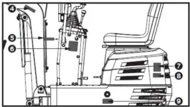
text_image
Technical diagram of an excavator with numbered components for identification4

text_image
Four safety warning symbols: warning triangle, triangular warning triangle, broken object, and person silhouette with directional arrow5

text_image
!6
text_image
SLOW FAST RUN CHOKE7
text_image
TRANSPORT Man-made Slope 3-point Lifting8
text_image
GREASE Platform Swing -100%9

text_image
Technical diagram of a mechanical device with numbered components and directional arrows indicating flow or movement.10
flowchart
graph TD
    A["Robot Arm"] --> B["Arrow to Robot Arm"]
    C["Robot Arm"] --> D["Arrow to Robot Arm"]
    E["Robot Arm"] --> F["Arrow to Robot Arm"]
    G["Robot Arm"] --> H["Arrow to Robot Arm"]
    I["Robot Arm"] --> J["Arrow to Robot Arm"]
    K["Robot Arm"] --> L["Arrow to Robot Arm"]
    M["Robot Arm"] --> N["Arrow to Robot Arm"]
    O["Robot Arm"] --> P["Arrow to Robot Arm"]
    Q["Robot Arm"] --> R["Arrow to Robot Arm"]
    S["Robot Arm"] --> T["Arrow to Robot Arm"]
    U["Robot Arm"] --> V["Arrow to Robot Arm"]
    W["Robot Arm"] --> X["Arrow to Robot Arm"]
    Y["Robot Arm"] --> Z["Arrow to Robot Arm"]
    AA["Robot Arm"] --> AB["Arrow to Robot Arm"]
    AC["Robot Arm"] --> AD["Arrow to Robot Arm"]
    AE["Robot Arm"] --> AF["Arrow to Robot Arm"]
    AG["Robot Arm"] --> AH["Arrow to Robot Arm"]
    AI["Robot Arm"] --> AJ["Arrow to Robot Arm"]
    AK["Robot Arm"] --> AL["Arrow to Robot Arm"]
    AM["Robot Arm"] --> AN["Arrow to Robot Arm"]
    AO["Robot Arm"] --> AP["Arrow to Robot Arm"]
    AQ["Robot Arm"] --> AR["Arrow to Robot Arm"]
    AS["Robot Arm"] --> AT["Arrow to Robot Arm"]
    AU["Robot Arm"] --> AV["Arrow to Robot Arm"]
    AW["Robot Arm"] --> AX["Arrow to Robot Arm"]
11
text_image
Technical diagram of an industrial vehicle's internal components with numbered labels pointing to various parts.12
text_image
MAX. 10 CM ADJUSTABLE13
text_image
DANGER MAX.18°17
text_image
5 joystick looked14
text_image
DANGER18
natural_image
Three diagrams showing robotic arm movements with no text or symbols15

text_image
Four warning symbols: warning, broken, broken, and broken with a lightning bolt symbol16
text_image
ON OFF STARTtext_image
Technical diagram of a mechanical device with labeled components and numbered parts
natural_image
Technical line drawing of a mechanical assembly with no visible text or symbolstext_image
Technical diagram showing a multi-step assembly of an excavator with tool icons and dimension annotations in Chinese.1- Schraube M12 (x1)
text_image
Technical diagram of an excavator with labeled parts including base, levers, and clampstext_image
1 2 A 24mm 13mm 4mm1- Dünne Mutter M16 (x2)
2- Stellschraube M8x25 (x2)
Montage des Lenkers
text_image
Technical diagram of a mechanical device with labeled parts and a 16mm wrench icon1- Schraube M10x20 (x4)
Rückspiegel Montage
text_image
X 2 13mm 1 C1- Schraube M8x30 (x4)
natural_image
Technical line drawing of a vehicle's internal components, showing a seat assembly and engine compartment (no text or symbols)text_image
Technical diagram of an excavator with numbered parts for identification
text_image
15 16 17 18 19
text_image
Technical diagram of a mechanical device with numbered components for identificationtext_image
Technical diagram of a mechanical assembly with numbered components and directional arrows indicating motion or movement.text_image
Technical diagram showing mechanical assembly with numbered components and directional arrows indicating motion or movement.1- freischalten
2- Blockade
natural_image
Technical line drawing of a mechanical device with no visible text or symbols1- Hupenschalter

WICHTIG!
text_image
Technical diagram of a mechanical assembly with numbered components and directional arrows indicating motion or movement.1- Geschlossen
2- Kraftstoffhahn
3- Öffnen Sie
text_image
Technical diagram of a mechanical device with numbered components for identificationtext_image
Technical diagram of a mechanical assembly with labeled components and an inset showing a circular component with symbols 1, 2, 3 and a switch symbol.(1)- AUS
(2)- EIN
(3)- START
natural_image
Technical line drawing of a mechanical or electrical component with no visible text or symbols1- Betriebsanzeige
natural_image
Technical line drawing of a mechanical device with no visible text or symbolstext_image
Technical diagram of a mechanical assembly with numbered components, likely illustrating a gear or fan mechanism.1- Geschlossen
2- Kraftstoffhahn
3- Öffnen Sie

text_image
Technical diagram showing a mechanical excavator assembly with labeled parts and a downward arrow indicating process flow.text_image
Technical diagram of a mechanical assembly with numbered components and directional arrows indicating motion or movement.1- freischalten
2- Blockade
3- Verriegelungshebel
natural_image
Technical line drawing of a mechanical assembly with no visible text or symbolstext_image
Technical diagram of a tracked excavator with labeled parts and directional arrows indicating motion or assembly.natural_image
Technical diagram of a mechanical piping system with valve and valve components (no text or labels)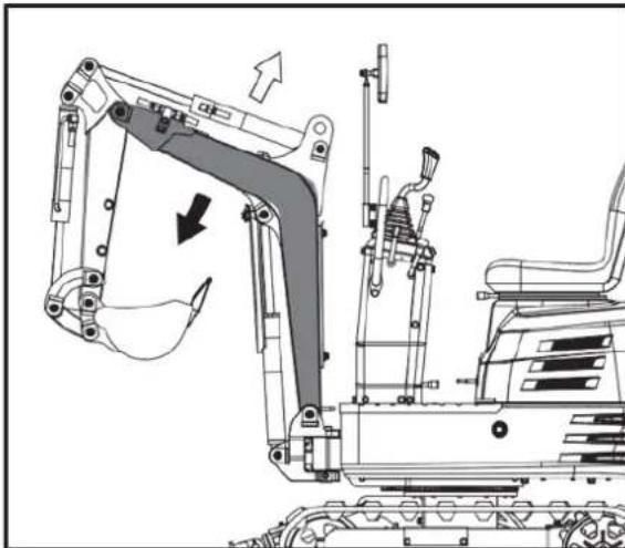
natural_image
Technical line drawing of an excavator assembly with no visible text or symbols
natural_image
Technical diagram of a mechanical or industrial system with pipes and a central component, showing directional arrows (no text or symbols)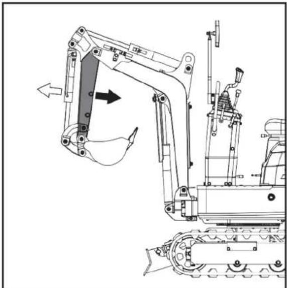
natural_image
Technical line drawing of a tracked excavator and tracked vehicle (no text or symbols)natural_image
Technical diagram of a mechanical piping system with directional arrows indicating flow or movement (no text or labels)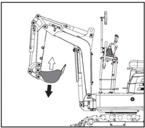
natural_image
Technical line drawing of an excavator with a downward load arrow (no text or symbols)SCHWENKBETRIEB (UNIT SWING)

ACHTUNG!
natural_image
Technical diagram of a mechanical piping system with valve and housing components (no text or labels)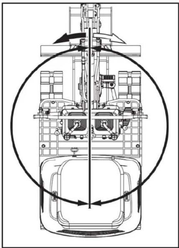
natural_image
Technical line drawing of a mechanical assembly with no visible text or symbolsAUSLEGERSCHWENKBETRIEB
text_image
Technical diagram of a mechanical assembly with labeled parts A, B, and numbered components 1 and 21 - Pedal. 2 - FRONT
text_image
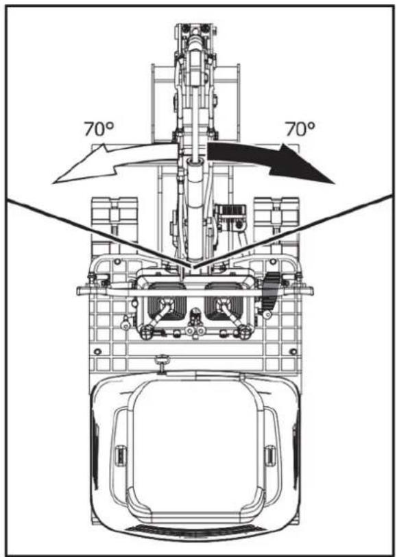
70° 70°AUSLEGERSCHWENKPEDAL

natural_image
Technical line drawing of a mechanical assembly with no visible text or symbols- Fix
BEDIENUNG DER PLANIERRAUPE
text_image
Technical diagram of a mechanical assembly with labeled parts A, B, and C, showing connections and components.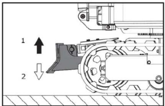
text_image
1 21.anheben. 2.Senken
natural_image
Technical line drawing of a mechanical assembly with no visible text or symbols1. Vorderseite
text_image
Technical diagram of a mechanical or electrical device with numbered components and directional arrows indicating flow or movement.natural_image
Technical line drawing of an excavator with labeled component '1' and directional arrow (no text or symbols beyond labels)natural_image
Two excavators in action, one lifting a boom and the other bending forward (no text or symbols)
natural_image
Line drawing of a bulldozer with a cross mark indicating failure, no text or symbols presentTURNS

ACHTUNG!
natural_image
Technical diagram showing a mechanical assembly with an upward arrow and a side-view view of a vehicle wheel (no text or symbols present)text_image
Technical diagram showing a device with internal components and a mechanical assembly with directional arrows indicating motion or transformation.text_image
Technical diagram showing a mechanical device with labeled components and directional arrow indicating rotation or assembly.text_image
Technical diagram showing a device with labeled components and a schematic view of its internal structure.text_image
Diagram showing a device with directional arrows and a mechanical assembly, labeled with components 1 and 2.text_image
Diagram showing airflow or movement of a device with labeled components and directional arrowsnatural_image
Line drawing of an excavator on a construction ground (no text or symbols)PARKEN AM HANG

natural_image
Technical line drawing of an excavator on a sloped terrain (no text or symbols)- Chock
natural_image
Line drawing of an excavator on a flatbed truck, no text or symbols present
LEBENSGEFAHR!
natural_image
Illustration of a worker pushing a dump truck on a slope with directional arrows (no text or symbols)text_image
250 to 300 mm 300 mm 250 to 300 mm 5000 mm 250 to 300 mmnatural_image
Line drawing of a construction vehicle with an excavator on a sloped terrain (no text or symbols)text_image
Technical diagram of a machine tool with numbered components and labeled partstext_image
Technical diagram of a mechanical assembly with numbered components and directional arrows indicating motion or movement.natural_image
Cartoon illustration of a truck with an excavator and a bucket, no text or symbols presentnatural_image
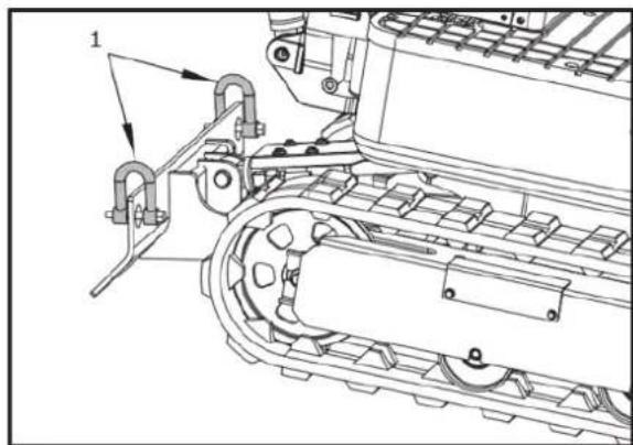
Technical line drawing of an excavator with labeled components (no text or symbols present)- Schäkel
natural_image
Technical line drawing of a tracked vehicle with mechanical components and mounting brackets (no text or symbols)- Schäkel
text_image
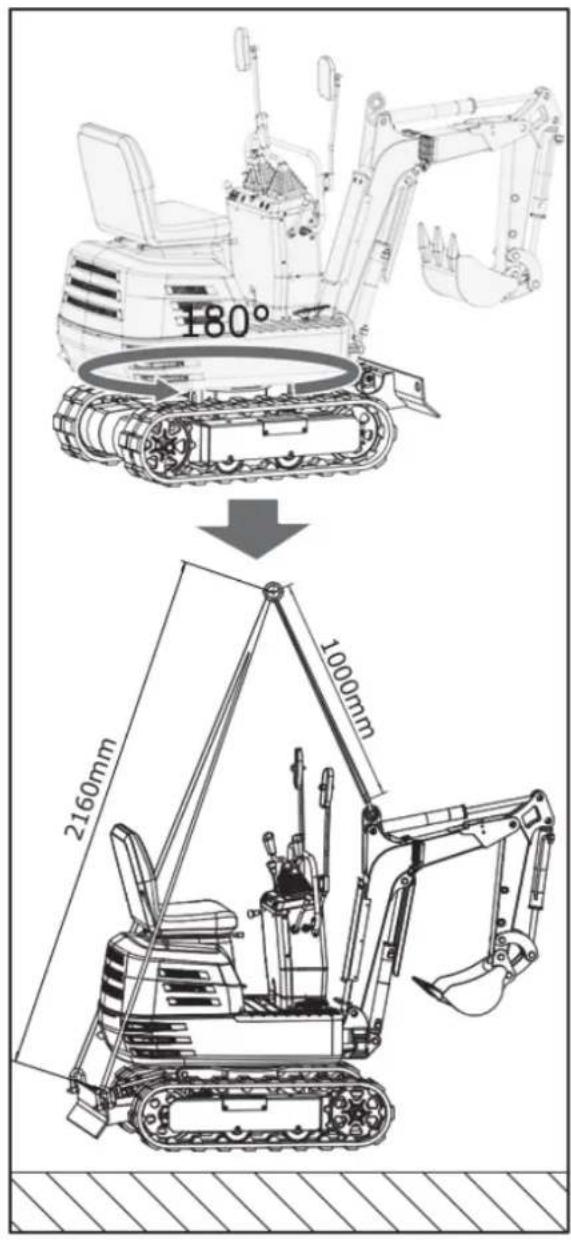
180° 2160mm 1000mmWARTUNG
WARTUNGSINTERVALLE
text_image
Technical diagram of a vehicle's internal components with numbered parts and directional arrows indicating motion or flow.- Motorhaubenschlüssel. 2. Motorhaube. 3. Offen.
text_image
Technical diagram of a tractor's internal components with numbered parts labeled 1 and 2natural_image
Technical line drawing of a mechanical assembly with no visible text or symbols1. Tankdeckel
natural_image
Technical line drawing of a mechanical assembly with no visible text or symbols- Entlüfter
natural_image
Technical line drawing of an electric motor assembly with labeled components (no text or symbols present)natural_image
Technical line drawing of a tracked vehicle showing internal components and engine (no text or symbols)- Vergaserentlüftung
Motorölstand prüfen

text_image
Technical diagram of a vehicle engine bay with numbered components and labeled partstext_image
Technical diagram of a tracked vehicle with labeled components and parts- Tankdeckel. 2. Angegebener Ölstand.
Schmierungspunkte

ACHTUNG!
text_image
Technical diagram of an excavator with labeled parts including arm, bucket, and guide componentsnatural_image
Technical line drawing of a mechanical assembly with labeled parts (no text or symbols present)natural_image
Technical line drawing of a mechanical assembly with no visible text or symbolsnatural_image
Technical line drawing of a bulldozer with visible mechanical components and tool path (no text or symbols)- Schaufelgelenkbolzen (x5)
Kühlgebläse prüfen

ACHTUNG!
text_image
Technical diagram of a tracked vehicle showing labeled components including engine, motors, and wheel assemblynatural_image
Technical line drawing of a mechanical component with internal parts and mounting holes (no text or symbols)text_image
Technical diagram of a vehicle engine bay with numbered components and labeled partsnatural_image
Technical line drawing of a mechanical assembly with labeled components (no readable text or symbols)natural_image
Technical line drawing of a tracked vehicle with visible tracks and components (no text or symbols)text_image
Technical diagram of a tracked vehicle with numbered components and directional arrows indicating assembly or movement.natural_image
Silhouette of a human head with motion arrows indicating sound or sound pressure (no text or symbols)natural_image
Line drawing of a hand using a tool to mark a grid on a grating (no text or symbols)
natural_image
Technical line drawing of a vehicle engine bay with internal components and no visible text or symbols- Zündkerze
Zündkerzen-Service
natural_image
Technical line drawing of a tracked vehicle with labeled components (no text or symbols present)- Schmiernippel
text_image
Technical diagram of a tracked vehicle with numbered components and directional arrows indicating motion or assembly.natural_image
Technical line drawing of a tracked robotic vehicle with visible engine and tracks (no text or symbols)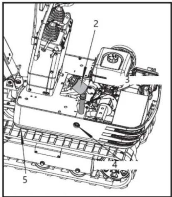
text_image
Technical diagram of a mechanical assembly with numbered components for identification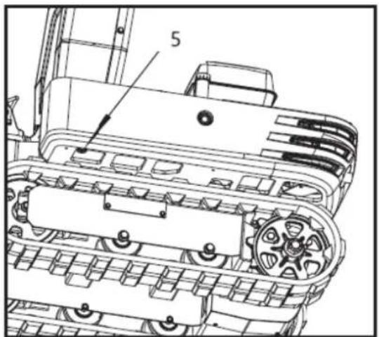
text_image
51- Ansaugfilter
2- Rücklauffilter
text_image
Technical diagram of a tracked vehicle with numbered components and labeled partsnatural_image
Technical line drawing of an excavator with tracked base and support structure (no text or symbols)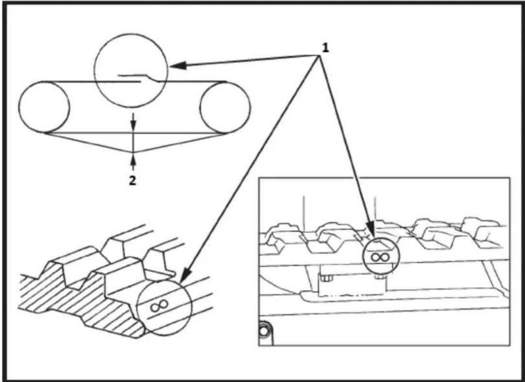
flowchart
graph TD
    A["Truck Belt"] --> B["Gear Mechanism"]
    B --> C["Final Product Inspection"]
    style A fill:#f9f,stroke:#333
    style C fill:#ccf,stroke:#333
text_image
Technical diagram of an automotive engine with labeled components and exploded viewtext_image
Technical diagram of a mechanical device with labeled components and exploded viewsbar
| Range | Value | |---|---| | 5W-30 | -20 | | 10W-30 | -10 | | 30 | 60 | | Rightward Arrow (labeled '30') | 80 | | Rightward Arrow (labeled '5W-30') | 30 | The chart displays a horizontal scale ranging from -30 to 100° F, with the rightmost arrow pointing further right. The leftmost arrow is leftward and extends slightly leftward.text_image
Line No 12V Rated/Blad Line No 3-1 Line No 25 White/Rad Line No 6S White/Rad Line No. 17 Red/Blue Line No. 12V Rated/Blad Line No. 12V Rated/Blad Line No. 12V Rated/Blad Line No. 12V Rated/Blad Line No. 12V Rated/Blad Line No. 12V Rated/Blad Line No. 12V Rated/Blad Line No. 12V Rated/Blad Line No. 12V Rated/Blad Line No 3-1 Line No. 3-1 Line No. 3-1 Line No. 3-1 Line No. 3-1 Line No. 3-1 Line No. 3-1 Line No. 3-1 Line No. 3-1 Line No. 3-1 Line No. 3-1 Line No. 3-1 Line No. 3-1 Line No. 3-2 Line No. 3-2 Line No. 3-2 Line No. 3-2 Line No. 3-2 Line No. 3-2 Line No. 3-2 Line No. 3-2 Line No. 3-2 Line No. 3-2 Line No. 3-2 Line No. 3-2 Line No. 3-2 Line No. Line No. Line No. Line No. Line No. Line No. Line No. Line No. Line No. Line No. Line No. Line No. Line No. Line No. Line No. Line No. Line No. Line No. Line No. Line No. Line No. Line No. Line No. Line No. Line No. Line No. Line No. Line No. Line No. Line No. Line No. Line No. Line No. Line No. Side Power Source (Power Source) Side Power Source (Power Source) Side Power Source (Power Source) Side Power Source (Power Source) Side Power Source (Power Source) Side Power Source (Power Source) Side Power Source (Power Source) Side Power Source (Power Source) Side Power Source (Power Source) Side Power Source (Power Source) Side Power Source (Power Source) Side Power Source (Power Source) Side Power Source (Power Source) Side Power Source (Power Source) Side Power Source (Power Source) Side power source (Power Source) Side power source (Power Source) Side power source (Power Source) Side power source (Power Source) Side power source (Power Source) Side power source (Power Source) Side power source (Power Source) Side power source (Power Source) Side power source (Power Source) Side power source (Power Source) Side power source (Power Source) Side power source (Power Source) Side power source (Power Source) Side power source (Power Source) Side power source ( Power Source ) Side power source ( Power Source ) Side power source ( Power Source ) Side power source ( Power Source ) Side power source ( Power Source ) Side power source ( Power Source ) Side power source ( Power Source ) Side power source ( Power Source ) Side power source ( Power Source ) Side power source ( Power Source ) Side power source ( Power Source ) Side power source ( Power Source ) Side power source ( Power Source ) Side power source ( Power Source ) Side power source ( Power Source ) Sidepower source ( Power Source ) Sidepower source ( Power Source ) Sidepower source ( Power Source ) Sidepower source ( Power Source ) Sidepower source ( Power Source ) Sidepower source ( Power Source ) Sidepower source ( Power Source ) Sidepower source ( Power Source ) Sidepower source ( Power Source ) Sidepower source ( Power Source ) Sidepower source ( Power Source ) Sidepower source ( Power Source ) Sidepower source ( Power Source ) Sidepower source ( Power Source ) Sidepower source( Power Source ) Sidepower source( Power Source ) Sidepower source( Power Source ) Sidepower source( Power Source ) Sidepower source( Power Source ) Sidepower source( Power Source ) Sidepower source( Power Source ) Sidepower source( Power Source ) Sidepower source( Power Source ) Sidepower source( Power Source ) Sidepower source( Power Source ) Sidepower source( Power Source ) Sidepower source( Power Source ) Sidepower source( Power Source ) Sidepower source( Power Sources ) Sidepower source( Power Sources ) Sidepower source( Power Sources ) Sidepower source( Power Sources ) Sidepower source( Power Sources ) Sidepower source( Power Sources ) Sidepower source( Power Sources ) Sidepower source( Power Sources ) Sidepower source( Power Sources ) Sidepower source( Power Sources ) Sidepower source( Power Sources ) Sidepower source( Power Sources ) Sidepower source( Power Sources ) Sidepower source( Power Sources ) Sidepower source( Power Sources ) Sine-Snake-Snake-Snake-Snake-Snake-Snake-Snake-Snake-Snake-Snake-Snake-Snake-Snake-Snake-Snake-Snake-Snake-Snake-Snake-Snake-Snake-Snake-Snake-Snake-Snake-Snake-Snake-Snake-Snake-Snake-Snake-Snake-Snake-Snake- Sine-Snake-Snake-Snake-Snake-Snake-Snake-Snake-Snake-Snake-Snake-Snake-Snake-Snake-Snake-Snake-Snake-Snake-Snake-Snake-Snake-Snake-Snake-Snake-Snake-Snake-Snake-Snake-Snake-Snake-Snake-Snake-Snake-Smake-Smake-Smake-Smake-Smake-Smake-Smake-Smake-Smake-Smake-Smake-Smake-Smake-Smake-Smake-Smake-Smake-Smake-Smake-Smake-Smake-Smake-Smake-Smake-Smake-Smake-Smake-Smake-Smake-Smake-Smake-Smake-Smake-Smoke S/moke S/moke S/moke S/moke S/moke S/moke S/moke S/moke S/moke S/moke S/moke S/moke S/moke S/moke S/moke S/moke S/moke S/moke S/moke S/moke S/moke S/moke S/moke S/moke S/moke S/moke S/moke S/moke S/moke S/moke S/moke S/moke S/moke S/muke S/muke S/muke S/muke S/muke S/muke S/muke S/muke S/muke S/muke S/muke S/muke S/muke S/muke S/muke S/muke S/muke S/muke S/muke S/muke S/muke S/muke S/muke S/muke S/muke S/muke S/muke S/muke S/muke S/muke S/muke S/muke S/muke S/muke T/S/S/S/S/S/S/S/S/S/S/S/S/S/S/S/S/S/S/S/S/S/S/S/S/S/S/S/S/S/S/S/S/S/S/S/S/S/S/S/S/S/S/S/S/S/S/S/S/S/S/S/S/S/S/S/S/S/S/S/S/S/S/S/S/S/S/S/S/S/S/S/S/S/S/S/S/S/S/S/S/S/S/S/S/S/S/S/S/S/S/S/S/S/S/S/S/S/S/S/S,Sine-Vin, In, In, In, In, In, In, In, In, In, In, In, In, In, In, In, In, In, In, In, In, In, In, In, In, In, In, In, In, In, In, In, In, In, In, In, In, In, In, In, In, In, In, In, In, In, In, In, In, In, In,In, In, In, In, In, In, In, In, In, In, In, In, In, In, In, In, In, In, In, In, In, In, In, In, In, In, In, In, In, In, In,In, In Line: 0 In Line: 0 In Line: 0 In Line: 0 In Line: 0 In Line: 0 In Line: 0 In Line: 0 In Line: 0 In Line: 0 In Line: 0 In Line: 0 In Line: 0 In Line: 0 In Line: 0 In Line: 0 In Line: 0 In Line:0 In Line:0 In Line:0 In Line:0 In Line:0 In Line:0 In Line:0 In Line:0 In Line:0 In Line:0 In Line:0 In Line:0 In Line:0 In Line:0 In Line:0 In Line:0 In Line:0 In Line:0 In Line:0 In Line:0 In Line: In Line: In Line: In Line: In Line: In Line: In Line: In Line: In Line: In Line: In Line: In Line: In Line: In Line: In Line: In Line: In Line: In Line: In Line: In Line: In Line: In Line: In Line: In Line: In Line: In Line: In Line: In Line: In Line: In Line: In Line: In Line: In Line: In Line: IN line: IN line: IN line: IN line: IN line: IN line: IN line: IN line: IN line: IN line: IN line: IN line: IN line: IN line: IN line: IN line: IN line: IN line: IN line: IN line: IN line: IN line: IN line: IN line: IN line: IN line: IN line: IN line: IN line: IN line: IN line: IN line: IN line: IN line : IN line: IN line: IN line: IN line: IN line: IN line: IN line: IN line: IN line: IN line: IN line: IN line: IN line: IN line: IN line: IN line: IN line: IN line: IN line: IN line: IN line: IN line: IN line: IN line: IN line: IN line: IN line: IN line: IN line: IN line: IN line: IN line: IN line: II line: II line: II line: II line: II line: II line: II line: II line: II line: II line: II line: II line: II line: II line: II line: II line: II line: II line: II line: II line: II line: II line: II line: II line: II line: II line: II line: II line: II line: II line: II line: II line: II line: II in the middle section of the middle section of the middle section of the middle section of the middle section of the middle section of the middle section of the middle section of the middle section of the middle section of the middle section of the middle section of the middle section of the middle section of the middle section of the middle section of the middle section of the middle section of the middle section of the middle section of the middle section of the middle section of the middle section of the middle section of the middle section of the middle section OF INN is an active switch or control switch to open the main switch or control switch to open the main switch or control switch to open the main switch or control switch to open the main switch or control switch to open the main switch or control switch to open the main switch or control switch to open the main switch or control switch to open the main switch or control switch to open the main switch or control switch to open the main switch or control switch to open the main switch or control switch to open the main switch or control switch to open the main switch or control Switch to Open the main switch or control Switch to Open the main switch or control Switch to Open the main switch or control Switch to Open the main switch or control Switch to Open the main switch or control Switch to Open the main switch or control Switch to Open the main switch or control Switch to Open the main switch or control Switch to Open the main switch or control Switch to Open the main switch or control Switch to Open the main switch or control Switch to Open the main switch or control Switch to Open the main switch / Open the main switch / Open the main switch / Open the main switch / Open the main switch / Open the main switch / Open the main switch / Open the main switch / Open the main switch / Open the main switch / Open the main switch / Open the main switch / Open the main switch / Open the main switch / Open the main switch / Open the main switch / Open the main switch / Open the main switch / Open the main switch / Open the main switch / Open the main switch/ Open the main switch / Open the main switch / Open the main switch / Open the main switch / Open the main switch / Open the main switch / Open the main switch / Open the main switch / Open the main switch / Open the main switch / Open the main switch / Open the main switch / Open the main switch / Open the main switch / Open the main switch / Open the main switch / Open the main switch / Open the main switch / Open the main switch / Open the main switch / Open the main switch / Open the main switch / Open the main switch / Open the main switch / Open the main switch / Open the main switch / Open the main switch / Open the main switch / Open the main switch / Open the main switch / Open the main switch / Open the main switch / Open the main switch / Open the main switch / Open the main switch / Open the main switch / Open the main switch / Open the main switch / Open the main switch / Open the main switch /Open the main switch /Open the main switch /Open the main switch /Open the main switch /Open the main switch /Open the main switch /Open the main switch /Open the main switch /Open the main switch /Open the main switch /Open the main switch /Open the main switch /Open the main switch /Open the main switch /Open the main switch /Open the main switch /Open the main switch /Open the main switch /Open the main switch /Open the main switch /open the main switch /Open the main switch /Open the main switch /Open the main switch /Open the main switch /Open the main switch /Open the main switch /Open the main switch /Open the main switch /Open the main switch /Open the main switch /Open the main switch /Open the main switch /Open the main switch /Open the main switch /Open the main switch /Open the main switch /Open the main switch /Open the main switch /Open the main switch /One an active shout or control shout is required for each shout is required by a minimum one shout is required by a minimum one shout is required by a minimum one shout is required by a minimum one shout is required by a minimum one shout is required by a minimum one shout is required by a minimum one shout is required by a minimum one shout is required by a minimum one shout is required by a minimum one shout is required by a minimum one shout is required by a minimum one shout is required by a minimum one shout is needed by a minimum one shout is needed by a minimum one shout is needed by a minimum one shout is needed by a minimum one shout is needed by a minimum one shout is needed by a minimum one shout is needed by a minimum one shout is needed by a minimum one shout is needed by a minimum one shout is needed by a minimum one shout is needed by a minimum one shout is needed by a minimum one shout is needed by a minimumone shout is needed by a minimum one shout is needed by a minimum one shout is needed by a minimum one shout is needed by a minimum one shout is needed by a minimum one shout is needed by a minimum one shout is needed by a minimum one shout is needed by a minimum one shout is needed by a minimum one shout is needed by a minimum one shout is needed by a minimum one shout is needed by a minimum one shout is required by a minimum one shout is required by a minimum one shout is required by a minimum one shout is required by a minimum one shout is required by a minimum one shout is required by a minimum one shout is required by a minimum one shout is required by a minimum one shout is required by a minimum one shout is required by a minimum one shout is required by a minimum one shout is required by a minimumone shout is needed by a minimum one shout is needed by a minimum one shout is needed by a minimum one shout is needed by a minimum one shout is needed by a minimum one shout is needed by a minimum one shout is needed by a minimum one shout is needed by a minimum one shout is needed by a minimum one shout is needed by a minimum one shout is needed by a minimum one shout is needed by a minimumone shout is required by a minimum one shout is required by a minimum one shout is required by a minimum one shout is required by a minimum one shout is required by a minimum one shout is required by a minimum one shout is required by a minimum one shout is required by a minimum one shout is required by a minimum one shout is required by a minimum one shout is required by a minimum one shout is required by a minimum one shout is requireby an active shout of an active shout of an active shout of an active shout of an active shout of an active shout of an active shout of an active shout of an active shout of an active shout of an active shout of an active shout of an active shout of an active shout of an active shout of an active shout of an active shout of an active shout of an active shout of an active shout of an active shout at any time point on an active shout at any time point on an active shout at any time point on an active shout at any time point on an active shout at any time point on an active shout at any time point on an active shout at any time point on an active shout at any time point on an active shout at any time point on an active shout at any time point on an active shout at any time point on an active shout at any time point onan active shout at any time point on an active shout at any time point on an active shout at any time point on an active shOUT at any time point on an active shOUT at any time point on an active shOUT at any time point on an active shOUT at any time point on an active shOUT at any time point on an active shOUT at any time point on an active shOUT at any time point on an active shOUT at any time point on an active shOUT at any time point on an active ShOUT at any time point on an active ShOUT at any time point on an active ShOUT at any time point on an active ShOUT at any time point on an active ShOUT at any time point on an active ShOUT at any time point on an active ShOUT at any time point on an active ShOUT at any time point onan active ShOUT at any time point onan active ShOUT at any time point onan active ShOUT at any time point onan active ShOUT at any time point onan active ShOUT at any time point onan active ShOUT at any time point onan active ShOUT at any time point onan active ShOUT at any time point onan active ShOUT at any time point onan active ShOUT at any time point onan active ShOUT at any time pointon an active ShOUT at any time point onan active ShOUT at any time point onan active ShOUT at any time point onan active ShOUT at any time point onan active ShOUT at any time point onan active ShOUT at any time point onan active ShOUT at any time point onan active ShOUT at any time point onan active ShOUT at any time points onan active ShOUT at any time points onan active ShOUT at any time points onan active ShOUT at any time points onan active ShOUT at any time points onan active ShOUT at any time points onan active ShOUT at any time points onan active ShOUT at any time points onan active ShOUT at any time points onan active ShOUT at any time points onan active ShOUT at any time points onan active ShOUT at any time pointson an active ShOUT at any time points onan active ShOUT at any time points onan active ShOUT at any time points onan active ShOUT at any time points onan active ShOUT at any time points onan active ShOUT at any time points onan active ShOUT at any time points onan active ShOUT at any time pointson an active ShOUT at any time points onan active ShOUT at any time points onan active ShOUT at any time points onan activitoural operation under current conditions for current operation under current operation under current operation under current operation under current operation under current operation under current operation under current operation under current operation under current operation under current operation under current operation under current operation under current operation under current operation under current operation under current operation under current operation under current operation under current operation under current operation under current operation under current operation under current operation under current operation under current operation under current operation under current operation under current operation under current operation under current operation under current operation under current operation under current operation undercurrent operation under current operation under current operation under current operation under current operation under current operation under current operation under current operation under current operation under current operation under current operation under current operation under current operation under current operation under current operation under current operation under current operation under current operation under current operation under current operation under current operation under current operation under current operation under current operation under current operation under current operation under current operation under current operation under current operation under current operation under current operation under current operation under current operation under current action Under Current Action Under Current Action Under Current Action Under Current Action Under Current Action Under Current Action Under Current Action Under Current Action Under Current Action Under Current Action Under Current Action Under Current Action Under Current Action Under Current Action Under Current Action Under Current Action Under Current Action Under Current Action Under Current Action Under Current Action Under Current Action Under Current Action Under Current Action Under Current Action Under Current Action Under Current Action Under Current Action Under Current Action Under Current Action Under Current Action Under Current Action Under Current Action Under Current Action Under Current ActionUnder Current Action Under Current Action Under Current Action Under Current Action Under Current Action Under Current Action Under Current Action Under Current Action Under Current Action Under Current Action Under Current Action Under Current Action Under Current Action Under Current Action Under Current Action Under Current Action Under Current Action Under Current Action Under Current Action Under Current Action Under Current Action Under Current Action Under Current Action Under Current Action Under Current Action Under Current Action Under Current Action Under Current Action Under Current Action Under Current Action Under Current Action Under Current Action Under Current Action UnderCurrent action under current action under current action under current action under current action under current action under current action under current action under current action under current action under current action under current action under current action under current action under current action under current action under current action under current action under current action under current action under current action under current action under current action under current action under current action under current action under current action under current action under current action under current action under current action under current action under current action under current action under currentaction overcurrent overcurrent overcurrent overcurrent overcurrent overcurrent overcurrent overcurrent overcurrent overcurrent overcurrent overcurrent overcurrent overcurrent overcurrent overcurrent overcurrent overcurrent overcurrent overcurrent overcurrent overcurrent overcurrent overcurrent overcurrent overcurrent overcurrent overcurrent overcurrent overcurrent overcurrent overcurrent overcurrent overcurrent overcurrent overcurrent overcurrent overcurrent overcurrent overcurrent overcurrent overcurrent overcurrent overcurrent overcurrent overcurrent overcurrent overcurrent overcurrent overcurrent overCURRENT >OFF >OFF >OFF >OFF >OFF >OFF >OFF >OFF >OFF >OFF >OFF >OFF >OFF >OFF >OFF >OFF >OFF >OFF >OFF >OFF >OFF >OFF >OFF >OFF >OFF >OFF >OFF >OFF >OFF >OFF >OFF >OFF >OFF >OFF >OFF >OFF >OFF >OFF >OFF >OFF >OFF >OFF >OFF >OFF >OFF >OFF >OFF >OFF >OFF >OFF >FF>FF>FF>FF>FF>FF>FF>FF>FF>FF>FF>FF>FF>FF>FF>FF>FF>FF>FF>FF>FF>FF>FF>FF>FF>FF>FF>FF>FF>FF>FF>FF>FF>FF>FF>FF>FF>FF>FF>FF>FF>FF>FF>FF>FF>FF>FF>FF>FF>FF>FF>text_image
Exploded view diagram of a mechanical assembly with numbered components for identification3.28. Teileliste
text_image
Exploded view diagram of a vehicle's internal components with numbered parts for identificationtext_image
Technical diagram of a tracked vehicle with numbered components and exploded view, likely for assembly or maintenance purposes.text_image
Technical diagram of a mechanical assembly with numbered components for identificationnatural_image
Technical line drawing of a tracked excavator with levers and motors (no text or symbols)natural_image
Technical line drawing of a tracked excavator assembly with mounting bracket and guide rails (no text or symbols)natural_image
Line drawing of an excavator with tracked blade and bucket (no text or symbols)Einbau des Harkens
natural_image
Technical line drawing of an excavator and tracked vehicle (no text or symbols)natural_image
Line drawing of an excavator with tracked base and mechanical components (no text or symbols)Daumen-Installation
text_image
Technical diagram showing the assembly of an excavator with labeled components and motion arrows indicating changes.natural_image
Technical line drawing of an excavator with tracked base and control panel (no text or symbols)Einbau der Klaue
natural_image
Technical line drawing of a tracked excavator with attached mechanical components (no text or symbols)natural_image
Line drawing of an excavator with tracked base and blade assembly (no text or symbols)natural_image
Technical line drawing of an excavator with tracked base and bucket, no text or symbols presentnatural_image
Line drawing of an excavator with tracked base and attached bucket (no text or symbols)text_image
M10 x 95 x 3text_image
Diagram illustrating three types of transportation methods: no litter, car storage, and vehicle collision.text_image
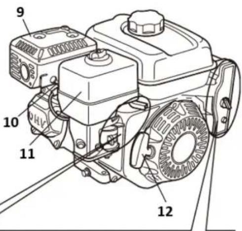
Technical diagram of an electric motor with numbered components for identification1- Schalldämpfer
2- ZÜNDKERZE:
3- Choke
text_image
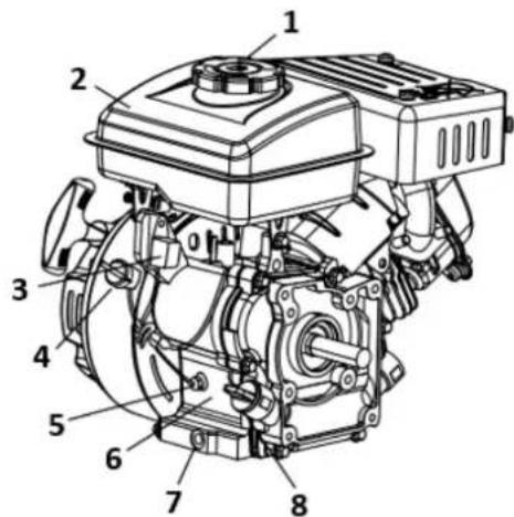
Technical diagram of a mechanical engine with numbered components labeled 1, 2, and 3.1- Treibstofftank
2- Ölablassschraube
3- Einfülldeckel/Peilstab
text_image
Technical diagram of a mechanical engine with numbered components for identification13
text_image
9 10 11 1213
text_image
Technical diagram of a mechanical assembly with numbered parts labeled 1, 2, and 3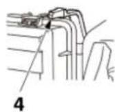
A
B
text_image
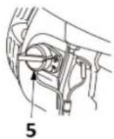
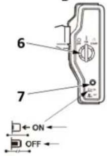
6 7 ON OFF1- Kraftstoffhebel
2- Chokehebel
3- Drosselkappenhebel
4- Chokehebel (Luftfilter Flachprofil-Typ)
5- Motorschalter
6- Motorschalter
7- Stromkreisschutz
text_image
Technical diagram of a mechanical device with labeled components and directional arrows indicating motion or assembly.natural_image
Illustration of a hand turning a mechanical component with a tool, labeled '1' (no text or symbols on the diagram itself)1- Startergriff
4.3. KONTROLLE VOR DEM BETRIEB
text_image
Technical diagram of a mechanical component with numbered parts and an arrow indicating direction or motion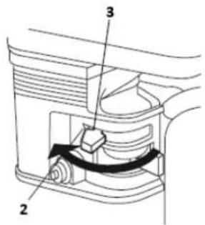
text_image
Technical diagram of a mechanical device with labeled parts 2, 3, and directional arrows indicating movement or force.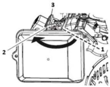
text_image
Technical diagram of a mechanical component with numbered parts and directional arrows indicating motion or flow.1- OPEN
2- CLOSE
3- Chokehebel
text_image
Technical diagram of a mechanical assembly with numbered components and directional arrows indicating motion or force.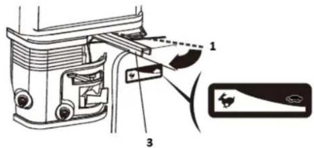
text_image
Technical diagram of a vehicle door assembly with labeled parts and component indicators1- Langsam
2- Schnell
3- Drosselkappenhebel
text_image
Technical diagram of a mechanical component with labeled parts and directional arrows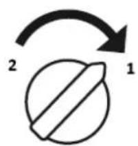
text_image
2 11- ON
2- AUS
3- Motorschalter
text_image
Technical diagram showing a hand operating a mechanical component with labeled parts 1 and 21-Startergriff
text_image
Technical diagram of a mechanical component with numbered parts and an angular annotation indicating rotation or movement.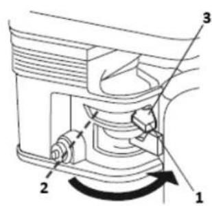
text_image
Technical diagram of a mechanical device with numbered components and directional arrows indicating motion or assembly.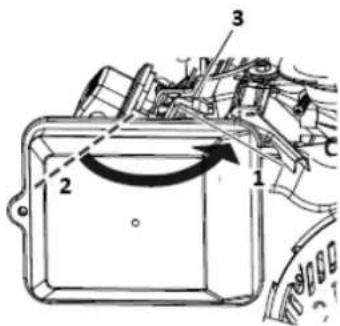
text_image
Technical diagram of a mechanical component with numbered parts and directional arrows indicating motion or movement.1- Öffnen Sie
2- Schließen Sie
3- Chokehebel
Motor anhalten
text_image
Technical diagram of a mechanical assembly with numbered components labeled 1, 2, and 3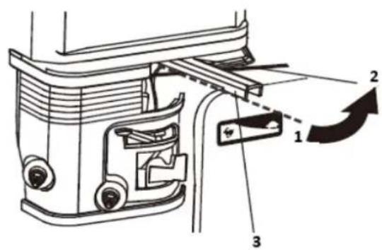
text_image
Technical diagram of a mechanical assembly with numbered components and directional arrows indicating motion or assembly.1- Schnell
2- Langsam
3- Drosselkappenhebel
text_image
1 2 O I 2 3 11- ON
2- AUS
3- Motorschalter
text_image
Technical diagram of a mechanical device with numbered components and directional arrows indicating motion or rotation.1- Öffnen Sie
2- Schließen Sie
3- Kraftstoffhebel
text_image
Technical diagram of a mechanical assembly with numbered components and directional arrows indicating motion or rotation.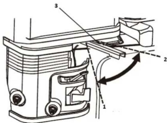
text_image
Technical diagram of a mechanical assembly with numbered components and directional arrows indicating motion or flow.1- Schnell
2- Langsam
3- Drosselkappenhebel
4.5. WARTUNG
text_image
Technical diagram showing a mechanical assembly with labeled components and a hand holding a tool, including numbered parts 1, 2, 3, and 4.text_image
Technical diagram showing mechanical assembly steps with labeled parts 1, 2, and 3
natural_image
Technical line drawing of a mechanical engine assembly (no text or symbols)text_image
Technical diagram showing mechanical assembly with labeled parts 1 and 2
text_image
Technical diagram of a mechanical component with labeled parts 3 and 41 - Obergrenze
2-Untere Grenze
3-Öleinfülldeckel/Peilstab
4-Ablassschraube
WARTUNG DES MOTORS
MOTORÖLEMPFEHLUNGEN
text_image
Technical diagram of a mechanical assembly with numbered parts, likely illustrating a valve or pump mechanism.natural_image
Illustration of two hands using a handheld tool to interact with a meshed device (no text or symbols present)flowchart
graph LR
    A["1 Hand washing in a bowl"] --> B["2 Downing liquid"]
    B --> C["3 Hand washing in a tray"]
    C --> D["4 Downing liquid"]
1-Sauber
text_image
Technical diagram of a mechanical assembly with numbered parts for identification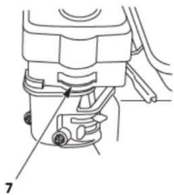
natural_image
Technical line drawing of a mechanical component with labeled parts (no text or symbols present)1-Luftfilterdeckel
2-Luftfiltereinsatz
3-Gitter
4-Flügel-Mutter
5-Kappe
text_image
Diagram showing a mechanical device with labeled parts, including a piston and valve assembly.F6RTC/F6TC:160F(E)/168F(E)/168FB(E)/TR163(E)/TR196(E)170F(E)/170FB(E)
/TR212(E)/TR223(E)/172F(E)/TR236(E)/177F(E)/TR270(E)/188F(E)/190F(E)/
190FB(E)/192F(E)/194F(E)/TR389(E)/TR420(E)/TR440(E)/TR460(E)/TR479(E)
Oder andere Äquivalente.
| F6RTC | F7RTC | |
| CHAMPION | RN6YC/RN6Y | RN7YC/RN7Y |
| NGK | BPR6ES | BPR7ES |
| DENSO | W20EPR_U | W22EPR_U |
| BOSCH | WR7DC | WR5DC |
Hinweis
text_image
Technical diagram showing mechanical assembly with labeled parts 1 and 2, likely for repair or maintenance instructions.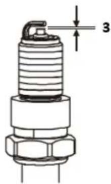
text_image
31- Zündkerzenschlüssel
2- Zündkerzenkappe
3-0,70-0,80mm
natural_image
Technical line drawing of a vehicle engine and its internal components, showing no text or symbolstext_image
Exploded view diagram of an electrical switch assembly with numbered parts for identification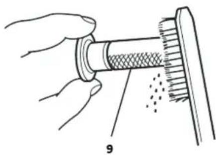
natural_image
Illustration of hands holding a cylindrical object with a meshed inner layer, partially covered by a flat surface (no text or symbols)text_image
Technical diagram of a coffee maker with labeled parts including feeding funnel, pump, and stand.1- Kraftstoffhebel
2- O-Ring
3- Sedimentbecher
4- Ablassschraube
5- Unterlegscheibe
text_image
Technical diagram of an automotive battery assembly with labeled parts 1, 2, and 31- MINUSKABEL (-) DER BATTERIE
2- MAGNETSCHALTER FÜR ANLASSER
3- PLUS(+)-BATTERIEKABEL
text_image
Technical diagram of a sewing machine with numbered parts and exploded view, likely for assembly or repair instructions.text_image
Technical diagram of a mechanical assembly with labeled parts 1 and 21- KABELHALTER
2- DROSSELHEBEL
177F(E)/TR270(E),188F(E)/190F(E)/TR389(E)/TR420(E)/TR440(E)/TR460(E)/TR479(E)
FERNGASGESTÄNGE
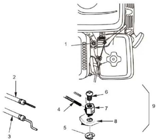
text_image
Technical diagram of a mechanical assembly with numbered parts, likely for repair or maintenance instructions.text_image
Technical diagram showing mechanical assembly with numbered components for maintenance or repair1- 4 mm SCHRAUBE
2- KABELHALTER
3- WIRE
4- 5 mm CIRCLIP
| IG | E | BAT | ST | |
| OFF | o—o | |||
| ON | ||||
| START | o—o |
text_image
Diagram of a scientific apparatus with labeled components and a sensor above it1-Obere Ebene
2-Niedere Ebene
Hinweis
This User Manual has been translated for your convenience using machine translation. Reasonable efforts have been made to provide an accurate translation; however, no automated translation is perfect nor is it intended to replace human translators. The official User Manual is the English version. Any discrepancies or differences created in the translation are not binding and have no legal effect for compliance or enforcement purposes. If any questions arise related to the accuracy of the information contained in the User Manual, please refer to the English version of those contents which is the official version.
Technical data
| Parameter description Parameter value | |
| Product name | Mini excavator |
| Model | HT-MIEX_01 |
| Operating weight [kg] | 562 |
| Bucket capacity [m3] | 0.011 |
| Digging force (Arm) [kN] | 4.3 |
| Digging force (Bucket) [kN] | 8.8 |
| Engine [cc] | 306 |
| Travel speed [km/h] | 1.7 |
| Swing speed [rpm] | 9.3 |
| Ground pressure [kpa] | 26.5 |
| Boom swing [degree] | Left 70/Right 70 |
| Hydraulic reservoir [L] | 12 |
1. General description
The user manual is designed to assist in the safe and trouble-free use of the device. The product is designed and manufactured in accordance with strict technical guidelines, using state-of-the-art technologies and components. Additionally, it is produced in compliance with the most stringent quality standards.
DO NOT USE THE DEVICE UNLESS YOU HAVE THOROUGHLY READ AND UNDERSTOOD THIS USER MANUAL.
To increase the product life of the device and to ensure trouble-free operation, use it in accordance with this user manual and regularly perform maintenance tasks. The technical data and specifications in this user manual are up to date. The manufacturer reserves the right to make changes associated with quality improvement. The device is designed to reduce noise emission risks to a minimum, taking into account technological progress and noise reduction opportunities.
Legend

Read instructions before use.
The product must be recycled.
WARNING! or CAUTION! or REMEMBER! Applicable to the given situation. (general warning sign)
Use ear protection. Exposure to loud noise may result in hearing loss.
Wear protective goggles.
Wear protective gloves.
Wear head protection.
Wear foot protection.
ATTENTION! Loud noise warning!
CAUTION! Spinning elements! Keep body parts away from moving parts of the unit.
ATTENTION! Hand crush hazard!
CAUTION! Danger of fire – flammable material!
Warning against poisoning by toxic substances!
CAUTION! Hot surface can cause burns!
Do not remove or modify factory-installed guards and protections
Smoking is forbidden while operating the unit or in its vicinity!
Do not operate the unit in enclosed spaces. The unit is intended for outdoor use only!
Caution on hills - risk of tipping over
Always leave the excavator bucket lowered to the ground when leaving the machine or finishing work.
Machine lifting point.
Do not operate the unit for long periods of time to avoid excessive inhalation of exhaust fumes.
Using the unit for transporting people or animals is prohibited!
Make sure there are no children or bystanders in the vicinity before operating the unit.

PLEASE NOTE! Drawings in this manual are for illustration purposes only and in some details may differ from the actual product.
2. Usage safety

ATTENTION! Read all safety warnings and all instructions. Failure to follow the warnings and instructions may result in serious injury or even death.
The terms "device" or "product" are used in the warnings and instructions to refer to:
Mini excavator.
2.1. Safety in the workplace
a) Be foresighted, watch what you are doing and use common sense when using the unit.
b) If you have any doubts as to whether the product is working properly or if it is damaged, contact the manufacturer's service department.
c) Only the manufacturer's service department can repair the unit. Do not carry out repairs yourself!
d) In case of open flames or fire, use only dry powder or snow (CO2) fire extinguishers to extinguish the live equipment.
e) Do not allow children or unauthorized persons in the work area (inattention may result in loss of control of the unit).
f) Running the unit can generate dust and splitter, protect bystanders against any harm.
g) Check the condition of the safety stickers regularly. Replace them if they are illegible.
h) Keep these instructions for use for future reference. If the unit is to be passed on to a third party, the operating instructions must also be handed over together with the unit.
i) Keep the packaging and small assembly parts out of the reach of children.
j) Keep the unit away from children and animals.

Remember! When using the device, protect children and other bystanders.
2.2. Personal safety
a) Do not operate this unit if you are tired, ill or under the influence of alcohol, drugs or medication that could impair your ability to operate the unit.
b) The unit is not intended to be used by persons (including children) with reduced mental, sensory or intellectual functions or persons who lack experience and/or knowledge unless they are supervised or have been instructed by a person responsible for their safety on how to operate the unit.
c) The unit may be operated by persons who are physically fit, capable of operating it and appropriately trained, and who have read this instruction manual and have been trained in occupational safety and health.
d) Use caution and common sense when operating this unit. A moment's inattention during operation may result in serious personal injury.
e) Use personal protective equipment as required when operating the unit as specified in Section 1 of the explanation of symbols. The use of appropriate, approved personal protective equipment reduces the risk of injury.
f) Do not overestimate your capabilities. Maintain body balance and equilibrium at all times during operation. This allows for better control of the unit in unexpected situations.
g) Do not wear loose clothing or jewellery. Keep hair, clothing, and gloves away from moving parts. Loose clothing, jewellery, or long hair can be caught in moving parts.
h) Before switching the unit on, remove any regulating tools or keys. Any tools or keys left in the rotating part of the unit may cause injury.
i) The unit is not a toy. Children should be watched to ensure that they do not play with the unit.
j) Do not place your hands or any objects inside the running unit!

ATTENTION! Despite the safe design of the device and its protective features, and despite the use of additional elements protecting the operator, there is still a slight risk of accident or injury when using the device. Stay alert and use common sense when using the device.
2.3. Safe use of the unit
a) Turn off the engine before adjusting, cleaning or maintaining the unit.
b) Keep unused equipment out of the reach of children and out of the reach of anyone unfamiliar with the unit or this instruction manual. These units are dangerous in the hands of inexperienced users.
c) Keep the unit in good working condition. Check before each use for general damage or damage to moving parts (cracks in parts and components or any other condition that may affect the safe operation of the unit). Make sure the fuel is not leaking. If damaged, have the unit repaired before use.
d) Keep the unit out of the reach of children.
e) Repairs and maintenance should be carried out by qualified personnel using only original spare parts. This will ensure the safety of use.
f) To ensure the designed operational integrity of the unit, do not remove factory-installed covers or loosen screws.
g) When transporting or moving the unit from storage to the place of use, observe the health and safety rules for manual handling applicable in the country where the unit is used.
h) Avoid situations in which the unit stops under heavy loads during operation. This can cause overheating of the drive elements and consequent damage to the equipment.
i) Do not touch moving parts or accessories unless the motor is turned off.
j) Do not leave the unit switched on unattended.
k) Clean the unit regularly to prevent permanent dirt build-up.
I) The provided value of vibration emission is measured according to the standard measurement methods. The value of vibration emission may change if the unit is used under different environmental conditions.
m) The unit is not a toy. Cleaning and maintenance must not be performed by children without adult supervision.
n) Do not tamper with the unit to alter its performance or design.
o) Keep the unit away from sources of fire and heat.
p) Do not overload the unit.
q) Take special care not to crush your feet when using the unit. Do not use the unit barefoot!
r) Use of the unit in the woods or high grass is recommended to reduce the risk of fire.
s) Always use the unit with both hands.
t) Do not make sudden movements or turns while operating the unit.
u) Do not shift gears when working on a hill or uneven ground.
v) Do not store fuel supplies near sources of fire and heat (such as a boiler, oven), electrical discharges, welding sparks that may ignite the fuel. Smoking is prohibited near fuel tanks.
w) Before refuelling, make sure the engine is turned off and cooled down and there are no fire sources near the refuelling area.
x) Try not to spill fuel.
y) When you have finished refuelling, carefully close the cap on the tank.
z) To start the unit after refuelling, move it at least 3 meters away from the refuelling point.
aa) Empty the fuel tank when transporting the unit.

ATTENTION! Although the product has been designed to be safe, with adequate safeguards, and despite the additional safety features provided to the user, there is still a slight risk of accident or injury when handling the unit. You are advised to use caution and common sense when using this product.
3. Use guidelines
The device is designed for digging, lifting, and transporting various materials in construction and landscaping tasks.
The user is liable for any damage resulting from unintended use of the device.
3.1. Symbols
| Symbol | Description |
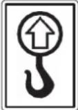 | 3-Point Lifting |
 | Alarm lamp “Battery charge” |

text_image
Vertical sequence of icons representing various environmental and operational symbols, including fuel, water, air, traffic, and weather.Ground wire disconnect switch (Negative switch)
Tie down the excavator
Grease
Gas
Hydraulic Oil
Cooling Fans
Lamp
Horn Button
Horn Position
Hours
Power Indicator
text_image
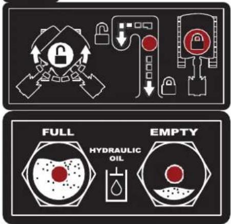
FULL HYDRAULIC OIL EMPTYInstruct user to lock or unlock the swing frame with the swing lock pin.
Always check the hydraulic oil lever before using the machine
text_image
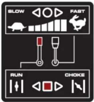
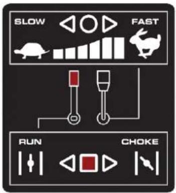
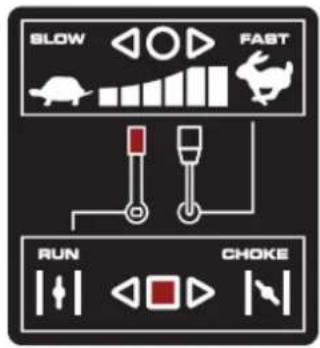
SLOW FAST RUN CHOKETHROTTLE CONTROL The throttle control regulates the speed of the engine. The throttle control moves between Slow and Fast

positions

text_image
POWER OUTLET 12V~ 15APower Outlet 12V,15A
text_image
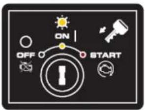
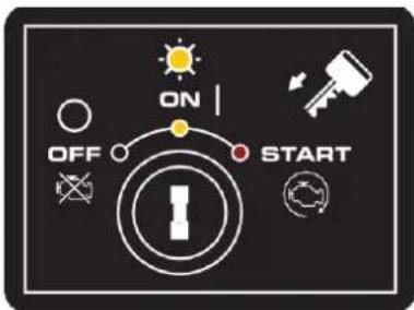
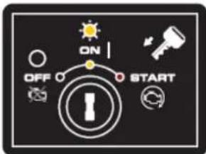
ON OFF STARTENGINE ON/OFF/START SWITCH The engine switch has three positions. OFF - engine will not start or run. ON - engine will run. Start - engine will ignite
flowchart
graph TD
    A["Robot Arm"] --> B["Sensor"]
    C["Robot Arm"] --> D["Sensor"]
    E["Robot Arm"] --> F["Sensor"]
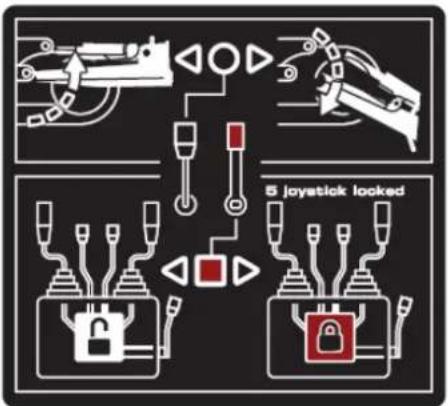
    G["5 joystick locked"] --> H["Locker"]
    I["5 joystick locked"] --> J["Locker"]
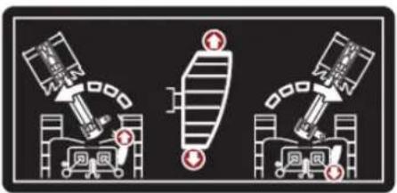
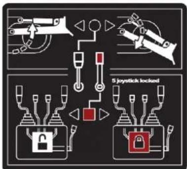
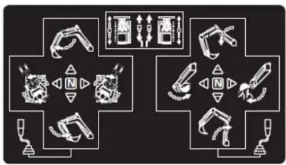
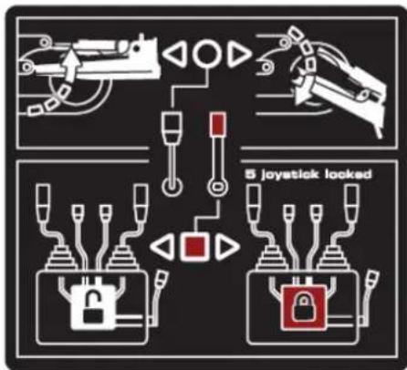
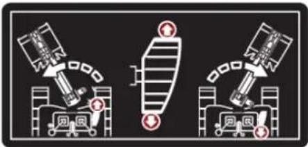
Pull back the black control lever to raise the dozer. Pushing the lever forward to lower the dozer.
natural_image
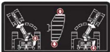
Three identical diagrams of robotic arms with labeled components, no text or symbols presentStep on the front of the pedal to swing the boom to left. Step on the rear of the pedal to swing the boom to the right.
text_image
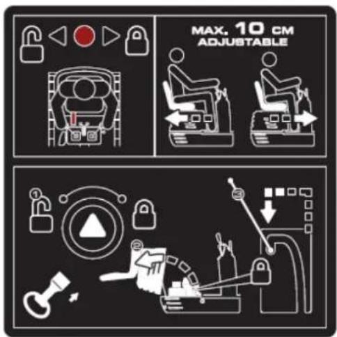
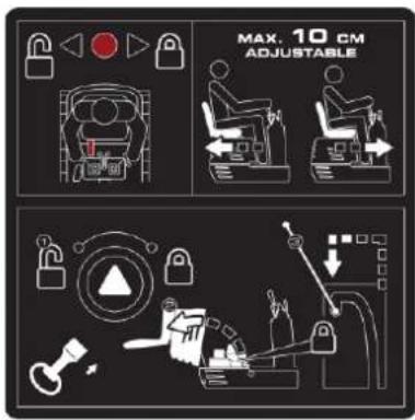
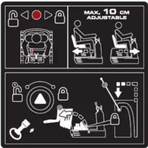
MAX. 10 CM ADJUSTABLEHold the lever towards to right side to unlock the seat, then do adjustment.

natural_image
Illustration of a magnifying glass examining a document with icons, no text presentManual Tube
text_image
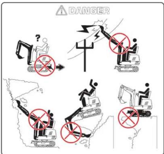
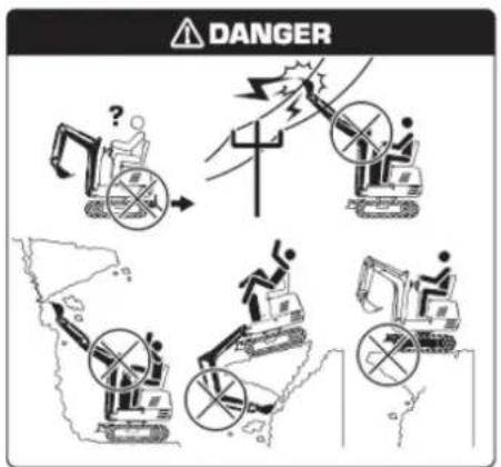
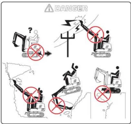
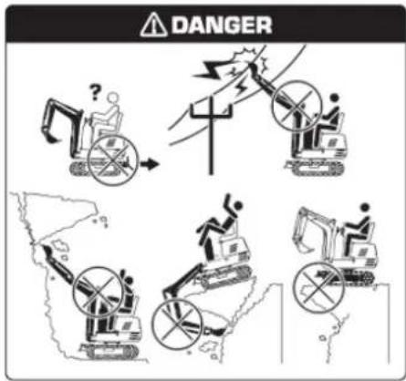
DANGERAvoid Work Site Hazards Avoid contact with gas lines, buried cables and water lines. Call utility line location services to identify all underground utilities before you dig. Prepare work site properly. Avoid operating near structures or objects that could fall onto the machine. Clear away debris that could move unexpectedly if run over. Avoid boom or arm contact with overhead obstacles or overhead electrical lines. Never move any part of machine or load closer than 3 m (10 ft) plus twice the line insulator length to overhead wires.
Keep bystanders clear at all times. Keep bystanders away from raised booms, attachments, and unsupported loads. Avoid swinging or raising booms, attachments, or loads over or near personnel. Use barricades or a signal person to keep vehicles and pedestrians away. Use a signal person if moving machine in congested areas or where visibility is restricted. Always keep signal person in view. Coordinate hand signals before starting machine. Operate only on solid footing with strength sufficient to support machine. When working close to an excavation, position travel motors away from the hole. Reduce machine speed when operating tool on or near ground when obstacles may be hidden (e.g., during snow removal or clearing mud, dirt, etc.).
text_image
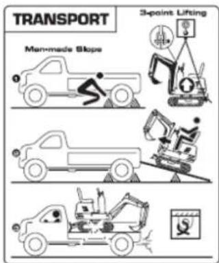
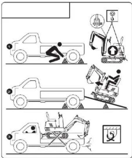
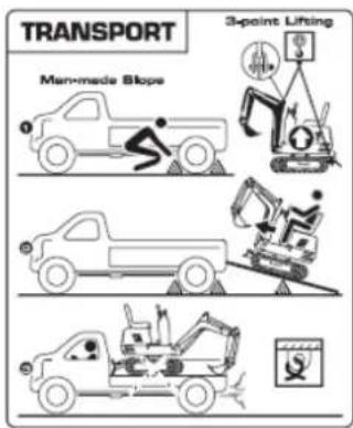
Diagram illustrating three scenarios of heavy machinery and a truck, with labeled icons and Chinese text.Using 3-point Lifting way or ramp to load or unload the excavator.
Warning: Apply the parking brakes of the truck, and block the drive wheels from both sides. Warning: use blocks or struts under the ramps and the truck bed.
Warning: Block the crawlers and tie down the excavator.
Warning: To avoid personal injury or death: After loading the machine on the truck, swivel the upper body around to the back of the truck and lock the swing frame with the swing lock pin. Lower the bucket and dozer onto the truck bed and then lock the boom with the lever before getting off. It is prohibited to operate the machine when operator stands on the ground.
text_image
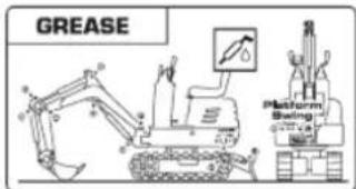
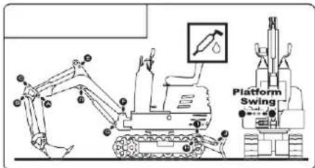
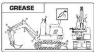
Platform SwingPeriodly grease the excavator
text_image
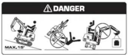
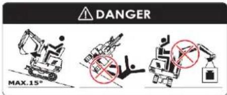
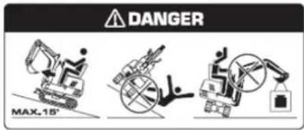
DANGER MAX.15°Avoid Machine Tip Over.
- Do not jump if the machine tips. You will be unlikely to jump clear and the machine may crush you.
- Load and unload from trucks or trailers carefully. Be sure truck is wide enough and on a firm level surface. Use loading ramps and attach them properly to truck bed. Avoid trucks with steel beds because tracks slip more easily on steel.
- Be careful on slopes. Use extra care on soft, rocky or frozen ground. Machine may slip sideways in these conditions. When traveling up or down slopes, keep the bucket on uphill side and just above ground level.
- Be careful with heavy loads. Using oversize buckets or lifting heavy objects reduces machine stability. Extending a heavy load or swinging it over side of undercarriage may cause machine to tip.
- Ensure solid footing. Use extra care when operating near banks or excavations that may cave-in and cause machine to tip or fall.
3.2. Basic operations
flowchart
graph TD
    A["1: Control Valve"] --> B["2: Robot Arm"]
    B --> C["3: Robot Arm"]
    C --> D["4: Robot Arm"]
    D --> E["5: Robot Arm"]
    E --> F["6: Robot Arm"]
    F --> G["7: Robot Arm"]
    G --> H["8: Robot Arm"]
    H --> I["9: Robot Arm"]
    I --> J["10: Robot Arm"]
    style A fill:#f9f,stroke:#333
    style B fill:#ccf,stroke:#333
    style C fill:#cfc,stroke:#333
    style D fill:#fcc,stroke:#333
    style E fill:#cff,stroke:#333
    style F fill:#ffc,stroke:#333
    style G fill:#cfc,stroke:#333
    style H fill:#fcc,stroke:#333
    style I fill:#ffc,stroke:#333
-
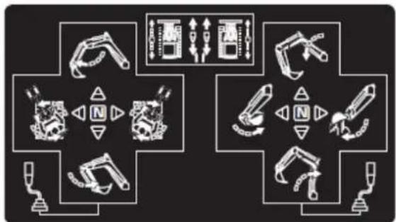
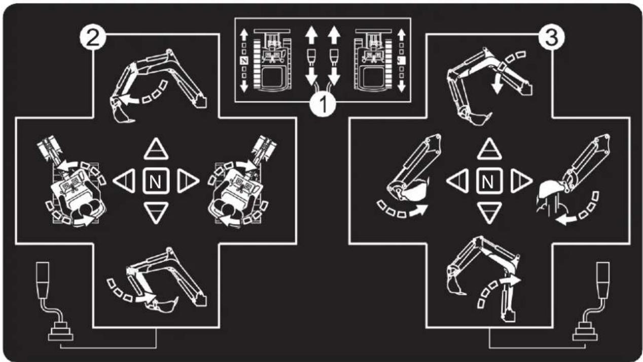
Pushing both drive levers forward, moves the machine forward, and vice-versa. The front of the machine is the direction where the dozer is present. Only operate one side drive lever to change the direction when the machine is stationary or travelling; Operate the left and right drive lever in opposite directions to achieve left and right spin turn.
-
Operation of the Arm and Unit Swing.
-
Operation of the Boom and Bucket.
3.3. Before starting the machine
-
Make yourself acquainted with the machine and be aware of its limits. Read this operator's manual carefully before starting the machine.
-
Obey the danger, warning and caution labels on the machine.
-
Track width 690mm. Operate in the correct track.
-
Do not use the machine under the influence of alcohol, medication or other substances. Fatigue is also dangerous.
-
Check the surroundings carefully before using the machine or when attachments are being attached.
- The machine is not intended to be used in a contaminated environment.
- Neither the machine as a whole nor its internal components are intended for use in potential explosive atmospheres.
• Pay attention to the overhead clearance with electric wires.
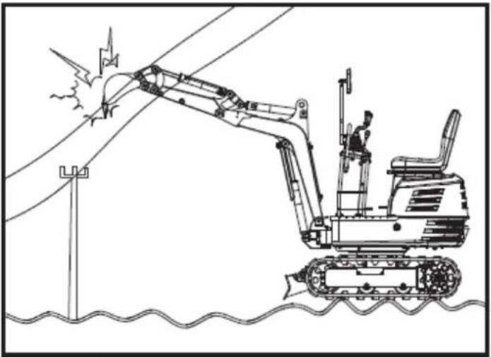
natural_image
Line drawing of an excavator on a utility pole with power lines and a flag, no text or symbols present- Check for pipes and buried cables.
- Check for hidden holes, hindrances, soft ground and overhangs.
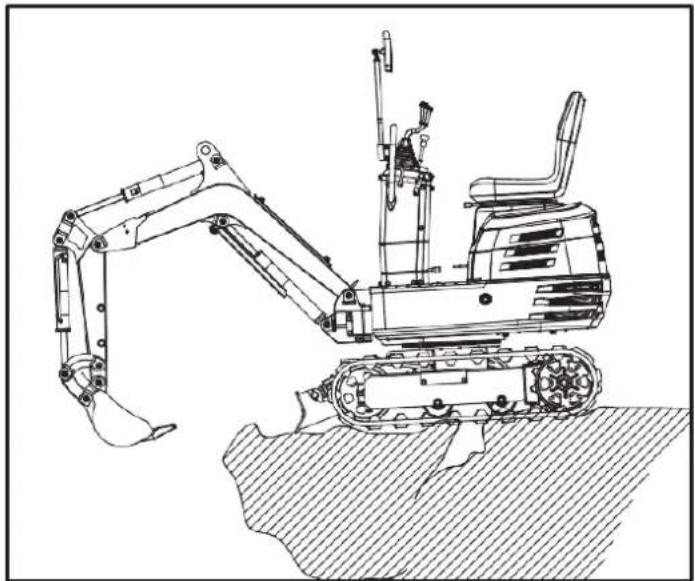
natural_image
Technical line drawing of an excavator on a sloped terrain (no text or symbols)- During excavating use do not allow any persons within the working range.
- Do not allow other persons to use the machine before having informed him on the exact operation and work instructions, and be assured that the operator's manual has been read and understood.
- Do not wear baggy, torn or too large clothing when working with the machine. Clothing can get caught in rotating parts or control elements which can cause accidents or injuries. Wear adequate safety clothing, e.g. safety helmet, safety shoes, eye protection, ear protection, working gloves, etc., as necessary and as prescribed by laws or statutes.
-
Do not allow passengers to get on any part of the machine seat during operation.
-
Check mechanical parts for correct adjustments and wear. Exchange worn or damaged parts immediately. Check nuts and bolts regularly for tight fitment. (for details see "Care and Maintenance").
- Keep your machine clean. Heavy soiling, grease, dust and grass can inflame and cause accidents or injuries.
- Use only authorized attachments.
- Before starting the machine, be absolutely sure that the machine has been filled with fuel, lubricated, greased and undergone other maintenance work.
- Do not modify the machine, otherwise it could lead to unforeseen safety problems.
3.4. Starting the machine
- Get into and out of the machine safely. Always face the machine. Always use handrails and available steps and keep yourself well balanced. Do not hold any of the control levers and switches. Do not jump on or off the machine, whether stationary or in motion.
- Start and control the machine only from the operator's seat. The driver should not lean out of his seat when the engine is running.
- Before starting the engine, make sure that all control levers are in their neutral positions.
- Do not start the engine by jumping the starter connections. Do not try to circumvent using the starter switch, otherwise the engine could start suddenly and the machine could move.
- Make sure that the dozer is on the front side. (The dozer must be raised.) If the swing frame has been turned 180, i.e. the dozer is, seen from the operator, "behind", then the travel direction is opposite to the drive direction of the levers (when activating the drive lever forwards, the machine, seen from the operator, will move backwards).
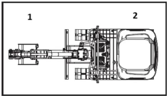
text_image
1 21- Front
2- Rear
-
Do not run the engine in closed or badly ventilated rooms. Carbon monoxide is colourless, odourless and deadly.
-
Keep all safety equipment and covers in place. Replace damaged or missing safety devices.
-
Precautions against tipping over. To secure safe operation, keep away from steep slopes and embankments. Do not swing the bucket downwards. Lower the dozer during digging. Keep the bucket as low as possible while driving upwards. Turn slowly on slopes. Do not keep the machine near the edges of trenches and banks, as the earth can give way due to the weight of the machine.
-
Watch out at all times where the machine is being moved to. Keep an eye out for hindrances.
-
Keep enough distance from trench and bank edges.
Safety for children
Tragedy can occur if the operator is not alert to the presence of children. Children generally are attached to machines and the work they do.
-
Never assume that children will remain where you last saw them.
-
Keep children out of the work area and under the watchful eye of another responsible adult.
-
Be alert and shut your machine down if children enter the work area.
-
Never carry children on your machine. There is no safe place for them to ride. They may fall off and be run over or interfere with your control of the machine.
-
Never allow children to operate the machine even under adult supervision.
-
Never allow children to play on the machine or on the implement.
-
Use extra caution when backing up, look behind and down-make sure area is clear before moving.
-
When parking your machine if at all possible, park on a firm, flat and level surface. Lower the implements to the ground, remove the key from the ignition and chock the crawlers.
3.5. After using the machine
Before leaving the machine,
- Bring the machine to hard even ground.
• Lower the attachments and the dozer blade on the ground. - Stop the engine.
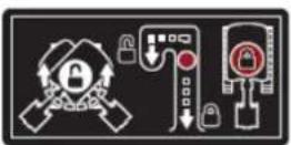
- Lock all control levers. Remove the key.
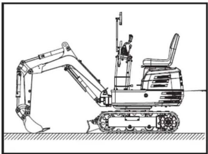
natural_image
Technical line drawing of an excavator with tracked arm and base mount (no text or symbols)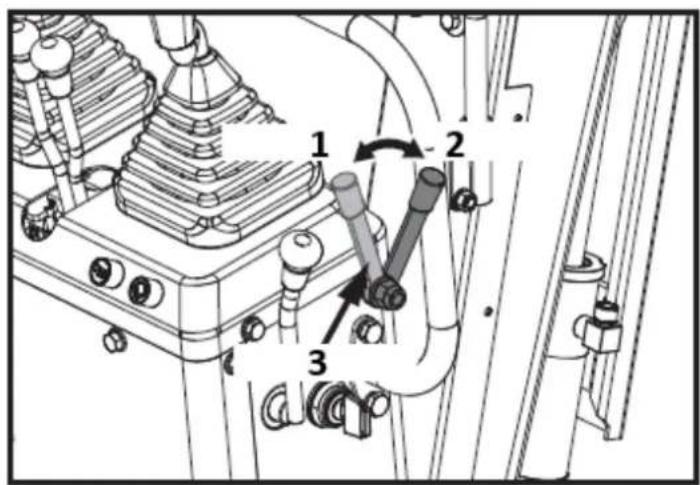
text_image
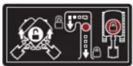
Technical diagram of a mechanical assembly with numbered components and directional arrows indicating motion or movement.1: Unlock
2: Lock
3: Lock lever
3.6. Loading and transporting the machine
- Observe all regulations concerning the transport of excavators on public roads.
- Use adequately long and robust ramps when loading on a truck. (for details see "TRANSPORTING THE MACHINE ON A TRUCK"); You can also lift the machine onto the truck. (for details see "LIFTING OF THE MACHINE").
- Do not change the running direction and to avoid a tipping over, do not try to swing the attachment crosswise to the loading ramps.
- After loading of the machine on a truck, swivel the upper body around to the back of the truck and engage the swing lock pin. Lower the attachment on the loading plane, release the pressure from the hydraulic system and lock the boom with the lever. Block the crawlers with blocks and wire down the machine. After loading the machine on a truck, tie down the undercarriage of the machine with a strong steel wire on the truck.
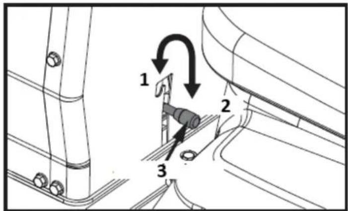
text_image
1 2 3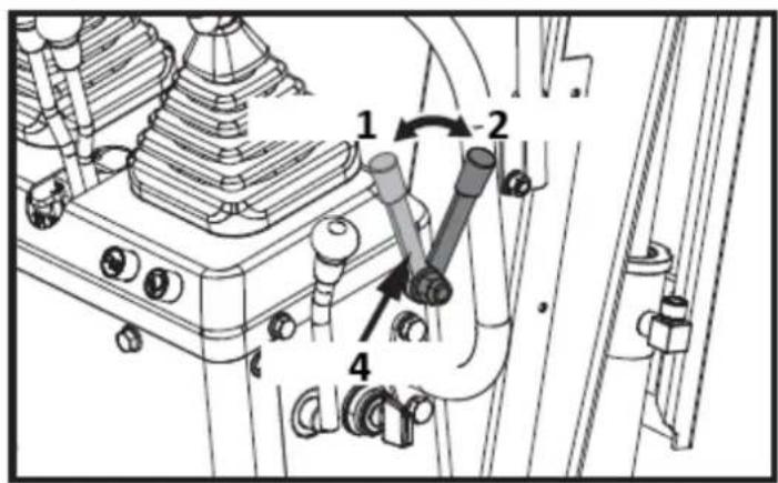
text_image
Technical diagram of a mechanical assembly with numbered components and directional arrows indicating motion or flow.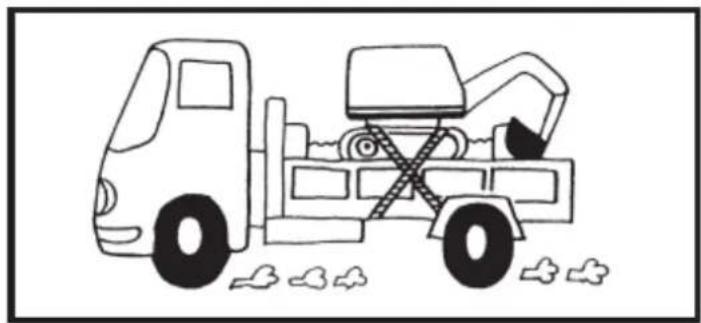
natural_image
Line drawing of a dump truck with an excavator and pile debris (no text or symbols)1-Unlock
2-Lock
3-Swing lock pin
4-Lock lever
- Do not brake abruptly with the machine loaded. Fatal accidents could happen.
3.7. Maintenance
Before doing maintenance work on the machine, place the machine on even solid ground, lower the attachments on the ground, stop the engine and release the cylinder pressure by actuating the levers. When dismantling hydraulic parts, make sure that the hydraulic oil has cooled down sufficiently to avoid burns.
Start maintenance work carefully, e.g. loosen screws slowly so that oil will not squirt out.
- Before doing work on the engine, the exhaust system, the heat protection shield and the hydraulics, let the machine cool down sufficiently.
- Turn off the engine at all times when filling with fuel. Avoid spilling and over-filling of fuel.
- Smoking is prohibited while fuelling and handling the battery! Keep sparks and fire away from the fuel tank and battery. Flammable gases escape from the battery.
- When the battery is dead, it can be started by pull the recoil starter.
- To avoid short-circuiting the battery, always remove the earth cable first and attach the plus cable first.
- Keep a first-aid box and a fire extinguisher at hand at all times.
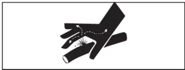
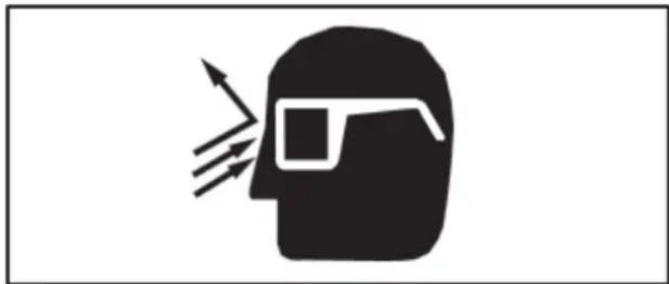
- Leaking hydraulic fluid has enough pressure to penetrate the skin and cause serious injuries. Leakages from pin holes can be totally invisible. Do not use the bare hand to check on possible leakages. Always use a piece of wood or cardboard. It is strongly recommended you use a face mask or eye protection.
Should injuries occur with leaking hydraulic fluid, contact a doctor immediately. This fluid can cause gangrene or serious allergic reactions.
natural_image
Diagram showing a hand holding a tool with motion arrows indicating movement (no text or symbols)- To avoid leakage of battery acid which contains heavy metals, do not throw the battery away.
- Observe all laws and regulations concerning the disposal of used oil, coolants, solvents, hydraulic fluids, battery acids and batteries.
- To avoid fire, do not heat the hydraulic components (tanks, pipes, hoses, cylinders) before they have been drained and washed.
- Use a face mask or eye protection to protect the eyes and respiratory system against dust and other foreign particles.
natural_image
Silhouette of a human head with sunglasses and motion lines, symbolizing vision or perception (no text or symbols)-
Do not crawl under the machine if the machine is only supported by the boom and arm or the dozer. The machine can tip over or lower itself due to hydraulic pressure loss. Always use safety struts or other appropriate supports.
-
Use no parts which are lined with asbestos. Do not use these kind of parts even if they can be installed.
-
Fire prevention
Machine and some attachments have components that are at high temperatures under normal operating conditions. The primary source of high temperatures is the engine and exhaust system. The electrical system, if damaged or incorrectly maintained, can be a source of arcing or sparks.
The following fire prevention guidelines will help to keep your equipment up and running efficiently and keep the risk of fire to a minimum.
- Blow off all accumulated debris near hot engine exhaust components such as cylinder head of gasoline engine and exhaust manifold as well as exhaust pipes and muffler more frequently when working in severe conditions.
- Clean out all accumulated flammable debris such as leaves, straw, pine needles, branches, bark, small wood chips and any other combustible materials from inside the machine belly pans or lower unit structures as well as from area in proximity to the engine.
- Inspect all fuel lines and hydraulic hoses for wear or for deterioration. Replace them immediately if they begin to leak.
- Examine electrical wiring and connectors frequently for damage. Repair any wires that are loose or frayed before operating the machine. Clean all electrical connections and tighten all electrical connections as necessary.
- Inspect the exhaust system daily for any signs of leakage. Check for broken pipes and muffler and also for loose or missing bolts, nuts and clamps. If any exhaust leaks or fractured parts are found, repairs must be completed prior to operation.
- Always keep a multipurpose fire extinguisher on or near the machine. Be familiar with the operation of the fire extinguisher.
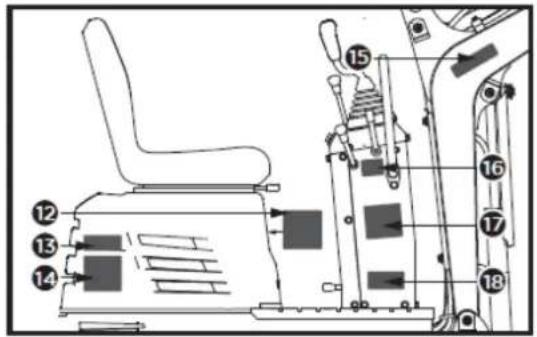
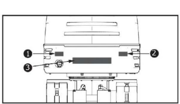
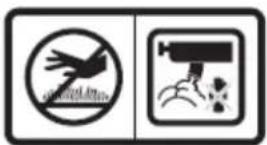
3.8. Danger, warning and caution labels
text_image
Technical diagram of a mechanical device with numbered components and labeled parts1
2

text_image
Two safety symbols: a hand crossed out with a prohibition sign and a person with a face detection icon.3

text_image
Collection of hazard warning symbols and icons, including safety, hazard protection, and human behavior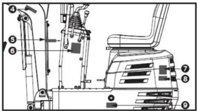
text_image
Technical diagram of an excavator with numbered components for identification and assembly reference.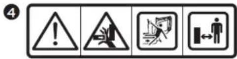
text_image
4
text_image
5 !6
text_image
SLOW FAST RUN CHOKE7
text_image
TRANSPORT Man-made Slope 3-point Lifting8
text_image
GREASE Platform Swing -2.7779

text_image
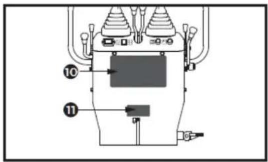
Technical diagram of a mechanical device with numbered components and labeled parts10
flowchart
graph TD
    A["Robot Arm"] --> B["Control Unit"]
    C["Truck"] --> D["Control Unit"]
    E["Wheel"] --> F["Control Unit"]
    G["Drain"] --> H["Control Unit"]
    I["Sensor"] --> J["Control Unit"]
    K["Feedback Loop"] --> L["Control Unit"]
    M["External Control"] --> N["Control Unit"]
    O["External Control"] --> P["Control Unit"]
    Q["External Control"] --> R["Control Unit"]
11
12
text_image
MAX, 10 CM ADJUSTABLE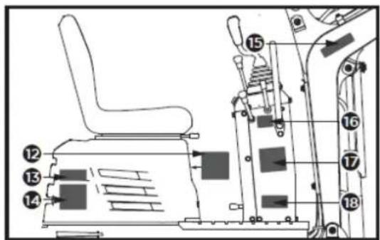
text_image
Technical diagram of an industrial vehicle's internal components with numbered parts labeled 12 to 1813
text_image
DANGER MAX.18°17
text_image
5 joystick looked14
text_image
DANGER18
natural_image
Three diagrams showing mechanical assembly or robotic arm configurations (no text or symbols)15

text_image
Four warning symbols: triangular warning triangle with exclamation mark, triangular hazard symbol, lightning bolt symbol, and lightning bolt symbol.16
text_image
ON OFF START3.9. Care of danger, warning and caution labels
- Keep danger, warning and caution labels, clean and free from obstructing material.
- Clean danger, warning and caution labels with soap and water, dry with a soft cloth.
- Replace damaged or missing danger, warning and caution labels with new labels from your dealer.
- If a component with danger, warning and caution label(s) affixed is replaced with new part, make sure new label(s) is (are) attached in the same location(s) as the replaced component.
- Mount new danger, warning and caution labels by applying on a clean dry surface and pressing any bubbles to outside edge.
Your dealer is always ready to help so that your machine offers the best performance. After having carefully read this manual, you will realize that much of the routine maintenance can be done by yourself. Your dealer is responsible for servicing and the delivery of spare parts. When ordering spare parts from your dealer, always mention the serial number of the machine and the engine.
Note these numbers right away in the supplied lines.
Excavator Model No. ____
Excavator Serial No. ____
Engine Serial No. ____
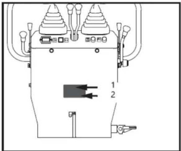
text_image
Technical diagram of a mechanical device with labeled components and directional arrows indicating flow or movement.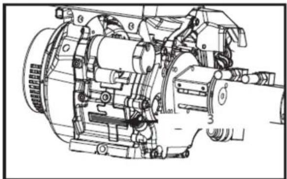
natural_image
Technical line drawing of a mechanical assembly with no visible text or symbols1- Machine Model No.
2- Machine Serial No.
3- Engine Serial No.
3.11. Unpacking the container
Remove the M8 fixing bolts that fix the iron frame and take off the iron frame. Loosen the M12 fixing bolt to release the bucket and remove the straps securing the machine. Lift the machine down.
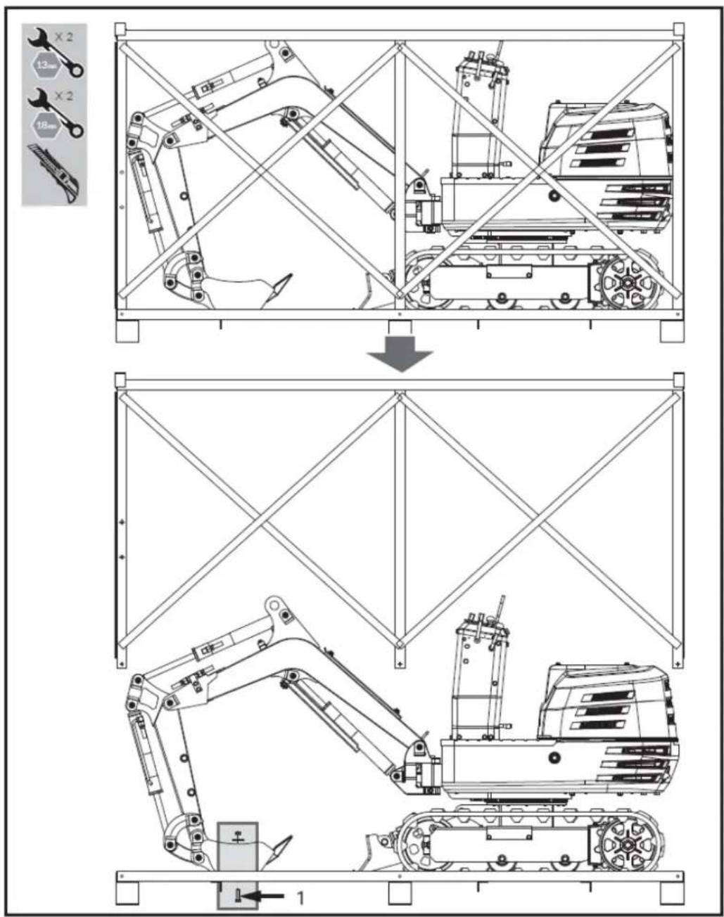
text_image
Technical diagram showing a mechanical assembly with tool coordinate axes and component layout, including a 1D model and a 2D view.1- Bolt M12 (x1)
3.12. Contents supplied
The machine comes partially assembled and is shipped in carefully packed package. After all the parts have been removed from the package, you should have:
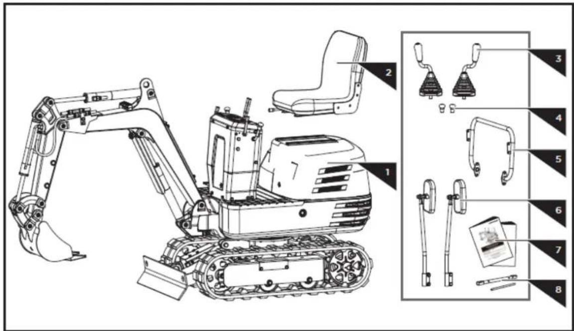
text_image
Technical diagram of an excavator with labeled parts including base, guide, and support components-
Main Body
-
Operator's Seat
-
Control Levers for Front Attachments
-
Drive Lever Knobs
-
Handlebar
-
Rearview Mirror
-
Operator's Manual & Engine Manual
-
Tools for Spark Plug Assembly
3.13. Assembly
Following the assembly directions below, you will assemble the machine in a few minutes.
Control Levers Assembly
- Take off the thin nut M16 from the control lever and loosen the set screw M8x25 and the nut on the side of the fixing hole.
Slide the control lever through the rubber sleeve and the thin nut M16 into the fixing hole on the control cabinet. Rotate it to an angle suitable for operation and lock the thin nut M16 to secure it. Tighten the set screw M8x25 and nut from the side. Repeat the same steps to mount the other lever.
- Screw the knobs to the drive levers.
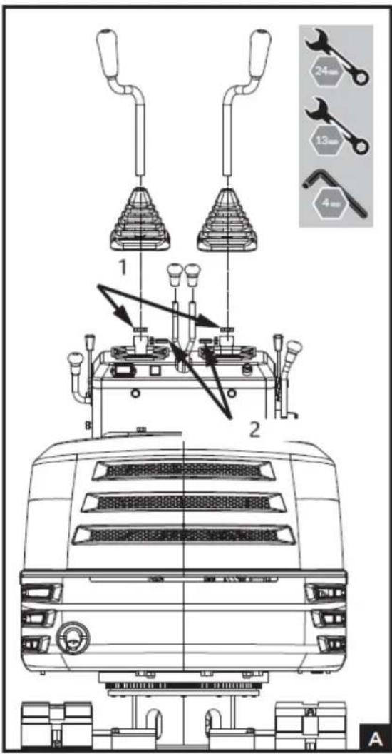
text_image
1 2 A 24mm 13mm 4mm1- Thin nut M16 (x2)
2- Set screw M8x25 (x2)
Handlebar Assembly
Screw out the M10x20 bolts, flat washers and spring washers from the control cabinet. Attach the handlebar to the sides of the control cabinet. Align the holes and secure the connection with the bolts and washers.
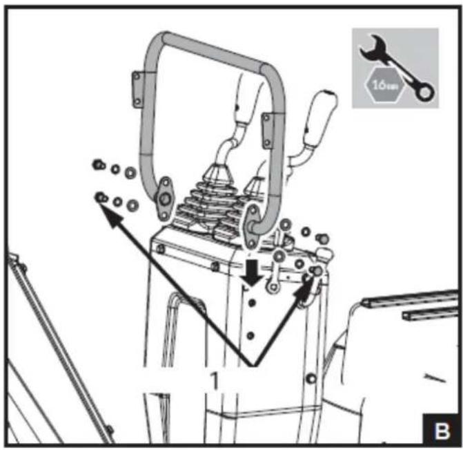
text_image
Technical diagram of a mechanical device with labeled parts and a 16mm wrench icon1- Bolt M10x20 (x4)
Rearview Mirror Assembly
Screw out the M8x30 bolts, washers and nuts from the mirror connectors. Fasten the connector to the brackets on the handlebar with the bolts, washers and nuts, making sure the mirrors face backwards as shown in the Fig. C.
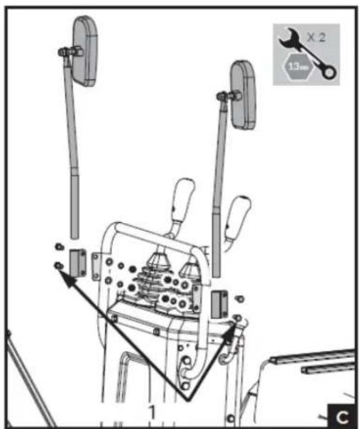
text_image
Technical diagram of a mechanical assembly with labeled components and a wrench icon for X2 tool1- Bolt M8x30 (x4)
Operator's Seat Assembly
Open the engine hood and install the seat from front to rear.
Adjust it to a suitable position by sliding it back and forth.
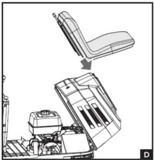
natural_image
Technical line drawing of a vehicle chassis with an L-shaped seat and internal components (no text or symbols)3.14. Description of machine parts
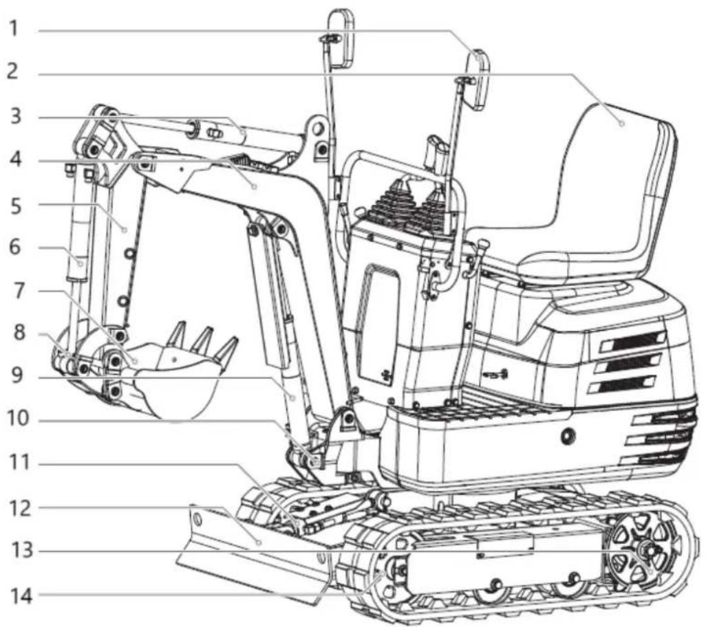
text_image
Technical diagram of an excavator with numbered parts for identification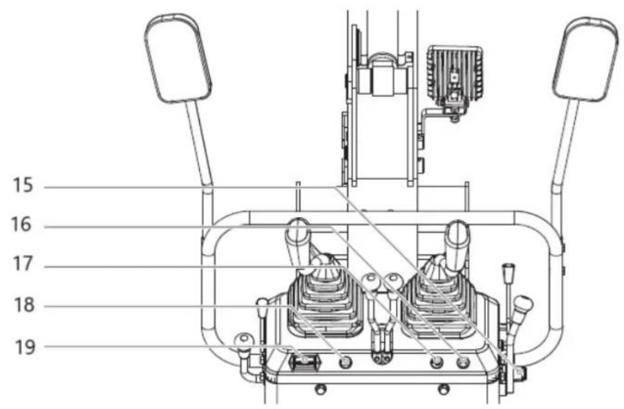
text_image
15 16 17 18 19
text_image
Technical diagram of a mechanical device with numbered components for identification| Part number Description | |
| 1 | Rearview mirror |
| 2 | Operator's seat |
| 3 | Arm cylinder |
| 4 | Boom |
| 5 | Arm |
| 6 | Bucket cylinder |
| 7 | Bucket |
| 8 | Bucket link |
| 9 | Boom cylinder |
| 10 | Swing bracket |
| 11 | Dozer cylinders |
| 12 | Dozer |
| 13 | Drive sprocket |
| 14 | Front idler |
| 15 | Starter switch |
| 16 | Working light switch |
| 17 | Horn switch |
| 18 | Power indicator |
| 19 | Hour meter |
| 20 | Control lever for dozer |
| 21 | Control lever for front attachments (right) |
| 22 | Right Drive Lever |
| 23 | Left Drive Lever |
| 24 | Control lever for front attachments (left) |
| 25 | Choke control lever of gasoline engine |
| 26 | Throttle lever |
| 27 | Boom swing pedal |
| 28 | Lock lever |
3.15. Before start
Handling the safety devices
Control lever lock

CAUTION!
- When the machine is not used or left unattended, be sure to place the bucket on the ground and lock the control levers. The front attachment may fall: it's dangerous. Also remove the key.
• The attachment control lever lock is located on the right side alike.
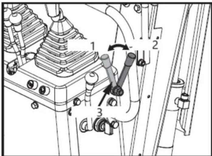
text_image
Technical diagram of a mechanical assembly with numbered components and directional arrows indicating motion or movement.1- Unlock
2- Lock
3- Lock lever
Swing lock pin
This pin is used to lock the swing frame. Set the lock pin to the "Lock" position and the swing frame gets locked to the track frame.

IMPORTANT! Before locking the lock pin, be sure to place the swing frame and the track frame parallel with each other.
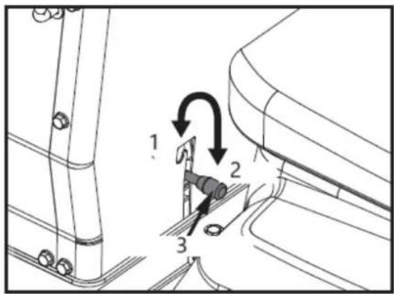
text_image
Technical diagram showing mechanical assembly with numbered components and directional arrows indicating motion or movement.1- Unlock
2- Lock
3- Swing lock pin
Daily checks
To avoid damage, it is important to check the condition of the machine before starting.

CAUTION! Do maintenance work on the machine only on even ground with the engine off and the safety devices in the "Lock" position.
Checks
• Walk around the machine and check for visual damage and wear.
- Check fuel level. Check engine oil level.
- Check hydraulic fluid level. Check air filter for clogging. Check hour meter.
- Check the light system.
- Check the condition of the danger, warning and caution labels. (See "Danger, warning and caution labels" in "Usage safety".)
3.16. Operation of the engine

CAUTION!
- Read "Usage safety" at the beginning of this operator's manual.
• Obey the danger, warning and caution labels on the machine.
- Exhaust gases are poisonous. Do not let the engine run in closed quarters without sufficient and adequate ventilation.
- Always start the engine from the operator's seat. Do not start the engine while standing next to the machine. Before starting the engine, sound the horn to get the attention of persons standing nearby.
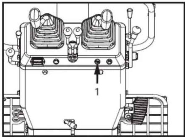
natural_image
Technical line drawing of a mechanical device with no visible text or symbols1- Horn switch

IMPORTANT!
- Do not use start help spray or similar fluids.
• In order not to overload the battery and starter, avoid start-ups of more than 10 sec.
- When the engine does not start in 10 sec., please set the interval to 20 sec. or more, and restart.
Starting the engine

CAUTION! The operators should always conduct the routine checks (see "MAINTENANCE").

NOTE! The engine fuel cock was set at "Open" position before leaving factory. No need to move the fuel cock lever when starting the engine. Only when the engine failed to be started, open the engine hood, check and make sure that the fuel cock is in the "Open" position.
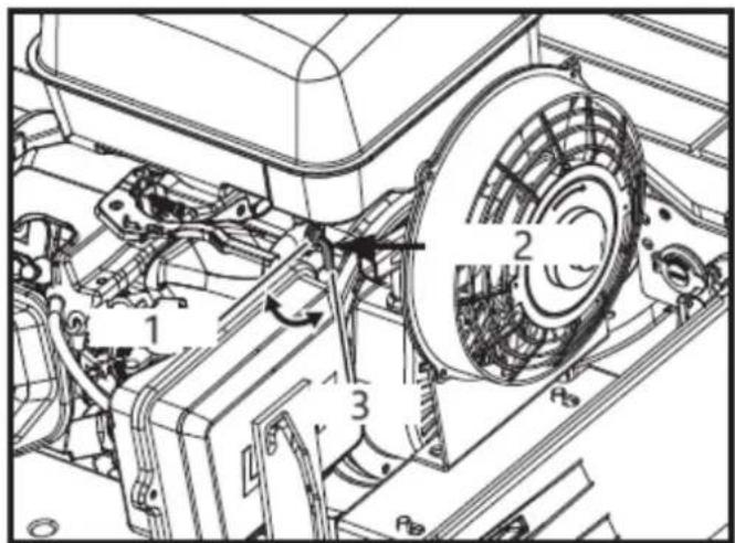
text_image
Technical diagram of a mechanical assembly with numbered components and directional arrows indicating motion or movement.1- Closed
2- Fuel cock
3- Open
Start the engine in the following manner:
- Before starting the engine, make sure that all control levers are in the neutral positions.
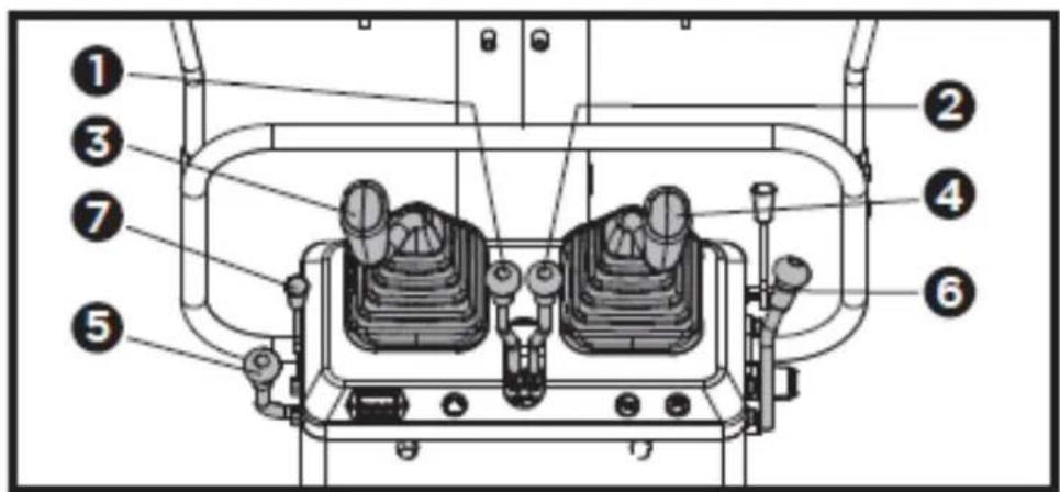
text_image
Technical diagram of a mechanical device with numbered components for identification(1) Left drive lever
(2) Right drive lever
(3) Attachment control lever (left)
(4) Attachment control lever (right)
(5) Throttle lever
(6) Control lever for dozer
(7) Choke control lever of gasoline engine
-
To start a cold engine, move the choke control lever to the CHOKE position. To restart a warm engine, leave the choke lever in the RUN position.
-
Move the throttle lever away from the SLOW position, about 1/3 of the way toward the FAST position.
-
Active the Key Ignition Switch by turning it fully clockwise toward "START". Release the key as soon as the engine starts, it will automatically return to the Run "ON" position. Do not active the key continuously for more than 5 to 10 seconds at a time.

text_image
Technical diagram showing a mechanical control panel with labeled buttons and indicators, including symbols like '1', '2', and '3'.(1)- OFF
(2)- ON
(3)- START
-
If the choke lever has been moved to the CLOSE position to start the engine, gradually move it to the RUN position as the engine warms up.
-
Check if power indicator has gone out. If the power indicator does not go out, stop the engine and check for the cause.
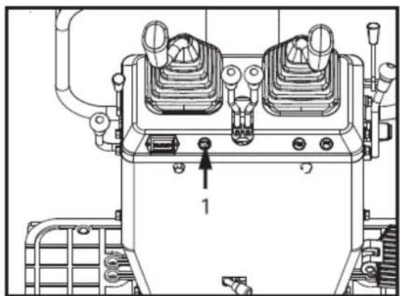
natural_image
Technical line drawing of a mechanical device with no visible text or symbols1- Power indicator
When the power indicator light is off, first check whether the fuse is blown. After the fuse is replaced, the fuse is normal, indicating that the battery is dead and needs to be charged; If the fuse is still blown after replacement, it is necessary to find professional maintenance personnel to repair the circuit.
Hour meter
The hour meter shows the total operating hours of the machine.
Meter reading
The meter counts up 1 for one operating hour. The electric meter is still counting if the engine stops but the key is in the "ON" position.
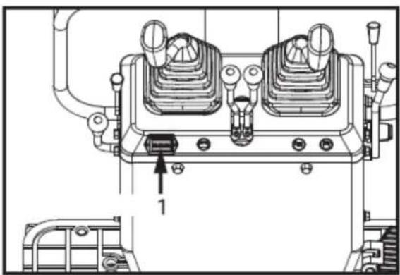
natural_image
Technical line drawing of a mechanical device with no visible text or symbols1- Hour meter
Checkpoints after Starting the Engine
After starting the engine, but before starting operation, check following points:
- Put the throttle lever in the "LOW" position and let the engine idle for approx. 5 minutes. This allows the engine lubricant to warm up and penetrate every part of the engine.

NOTE! This idling is usually called "Warm-up".
- Once the engine has warmed up, check:
• The alarm lamp "Battery charge" goes out when accelerating the engine.
• The colour of the exhaust gas is normal and no abnormal noises or vibrations are heard or felt.
• No fluid is leaking from pipes or hoses.
Should any following conditions arise, stop the engine immediately.
• The engine revolution increases or decreases suddenly.
- Sudden abnormal noises.
- Exhaust gas is black.

IMPORTANT!
-
In these cases, the machine must be checked and serviced according to the directions of the dealer.
• Let the engine warm up after start-up. -
Let the engine warm up after start-up for approx. 10 minutes under no load conditions. If the hydraulic fluid temperature is too low, the operation will be affected.
• Do not operate the machine under full load before the engine is warmed up enough.
Stopping the engine

WARNING!
- Do not keep the bucket or dozer in the lifted position, as a person could accidentally touch the levers and cause serious accidents.
• Lower all work attachments on to the ground, otherwise accidents could occur.
Let the engine idle for approx. 5 minutes to let it cool down.
- Put the throttle lever in idle position.
- Lower the work attachments carefully on the ground by activating the levers.
- To stop the engine, turn the key to the "OFF" position and remove the key.
Stop fuel cock

CAUTION! In the case of an emergency, or should the engine in idle position and key in the off position, still run, do like as below.
Open the engine hood and push the stop lever back and hold until the engine stops.
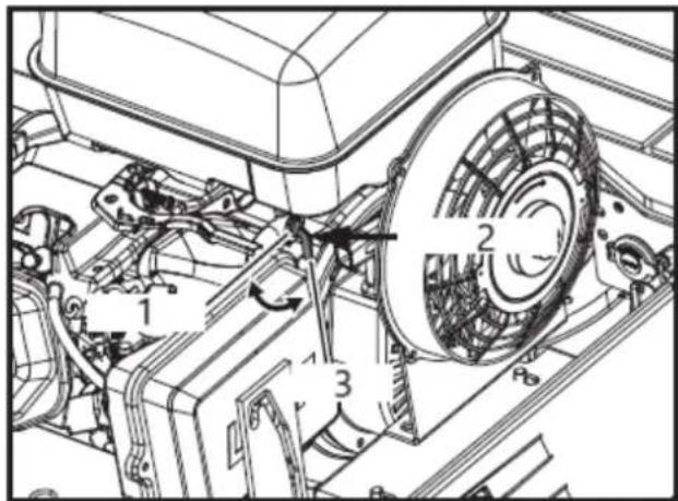
text_image
Technical diagram of a mechanical assembly with numbered components and directional arrows indicating motion or flow.1- Closed
2- Fuel cock
3- Open

IMPORTANT! If the engine does not stop with the key, contact your dealer.
3.17. Operation of the machine
Control observations during operation
Stop the Engine immediately if:
After starting the engine, but before starting operation, check following points:
• Sudden increase or decrease in engine revolution occurs.
- Sudden abnormal noises occur.
• Exhaust gases turn suddenly very dark.
Make following control observations during operation to be sure that everything functions normally.

WARNING! When the engine stops suddenly, push forward the right handrail to let the bucket fall down, so as not to cause misoperation, resulting in injury due to the bucket fall.
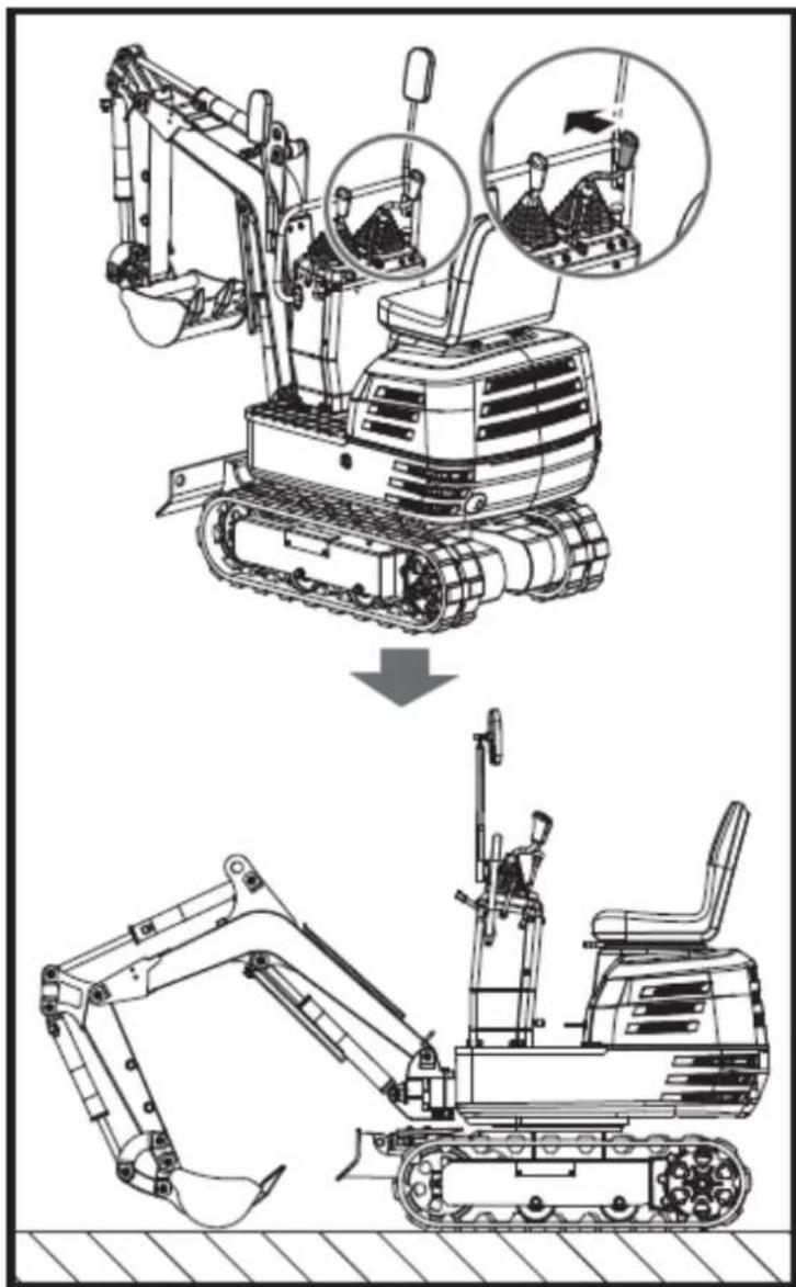
text_image
Technical diagram showing the installation of an excavator with labeled components and a downward arrow indicating process flow.Running-in of the new machine
The operation and care of the new machine influences its life span. Your new machine has been carefully checked and tested before leaving the factory. In spite of this, all movable components must run-in during the first 50 work hours. Do not work with full revolution and full loads during this period. It is most important to run-in your machine properly in order to achieve its full performance and longevity. During the running-in, the following points should be adhered to in all cases.
Do not Work with Full Revolutions or Full Loads during the First 50 Working Hours.
- Let the engine warm up sufficiently in the cold season.
• Do not let the engine rev-up more than necessary.
Oil Change in the Run-in Stage.
The lubrication oil plays a specially important role during the run-in phase of the machine. The numerous movable parts are not yet run-in, so that many fine metal particles can develop and cause damage or shorten the lifetime of many components. Pay attention to the oil change intervals and execute them sooner rather than later as necessary. See the subject "Care and Maintenance" for more details on the oil-change intervals.
Starting

CAUTION!
• No persons, other than those familiar with the machine, are allowed to use the machine.
- Do not allow any person other than the operator to ride on the machine.
Adjusting the Operator's Seat
1. Adjusting the Operator's Seat

CAUTION!
- Before adjusting the operator's seat, make sure that no one puts hands on the engine bonnet behind the seat.
• After having adjusted the seat, make sure that the seat adjuster has clicked into position.
To and fro: While holding up the to-and-fro adjustment lever, reposition the seat to and fro.
2. Bring the lock lever into the "Unlock" position.

CAUTION! Check safety aspects all around the machine.
Please bring the lock lever into the "Unlock" position, and raise the lower side of the bucket from the ground by 20 to 40 cm.
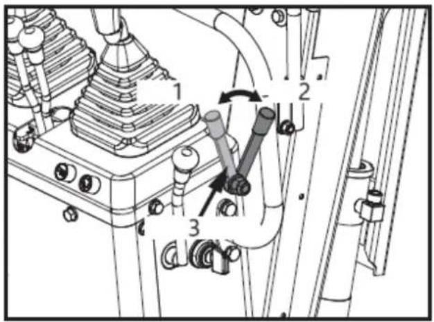
text_image
Technical diagram of a mechanical assembly with numbered components and directional arrows indicating motion or movement.1- Unlock
2- Lock
3- Lock lever
Working Light Switch
If the key is in the "ON" position, the lights will be switched on by tipping the switch.
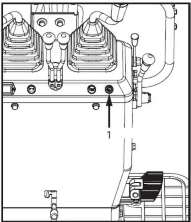
natural_image
Technical line drawing of a mechanical assembly with no visible text or symbols1- Working light switch

IMPORTANT! The ambient lighting of the machine must be above 500Lux.
Night operation

CAUTION! Visibility is reduced in darkness, so that the working light alone is not enough. Prepare additional lighting, observe safety rules as well as special regulations for night work.
Drive lever
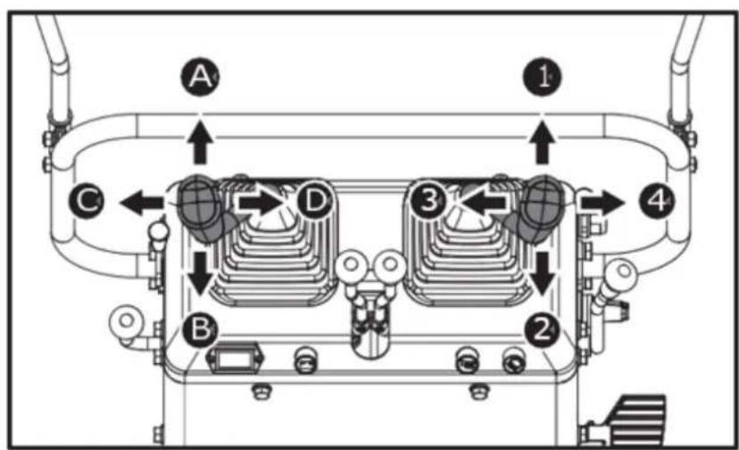
text_image
A 1 C D 3 4 B 2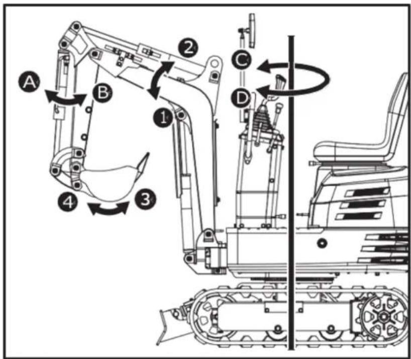
text_image
Technical diagram of a tracked excavator with labeled parts and directional arrows indicating motion or assembly.NOTE: See "SWIVEL MOVEMENT AND SWING MOVEMENT".
| Lever position | Movement | |
| Left Front Attachment Control Lever | A | Arm out |
| B | Arm in | |
| C | Swivel to left | |
| D | Swivel to right | |
| Right Front Attachment Control Lever | 1 | Boom lower |
| 2 | Boom raise | |
| 3 | Bucket dig | |
| 4 | Bucket dump | |
To raise the boom, pull the attachment control lever back.
The boom is equipped with a cushion cylinder which prevents excavated material in the bucket from fall-in out. By low hydraulic oil temperature, (e.g. right after starting the engine) the cushioning function will only be effected after a certain delay (approx. 3 to 5 seconds). This condition results from the viscosity of the hydraulic oil and is no sign of a malfunction.
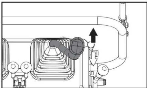
natural_image
Technical diagram of a mechanical piping system with valve and valve components (no text or labels)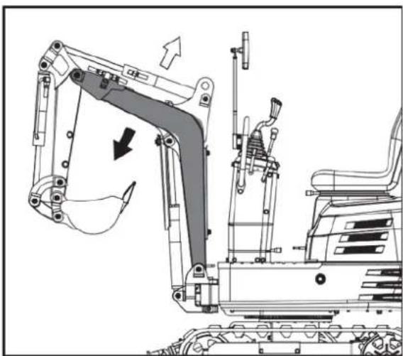
natural_image
Technical line drawing of an excavator assembly with no visible text or symbols
IMPORTANT! When lowering the boom, make sure that it does not hit the dozer and that the bucket teeth do not touch the dozer.
Pull back the left attachment control lever and the arm will be pulled in. To move the arm out, push the control lever towards the front.

IMPORTANT! When pulling in the arm, the movement may stop for a short moment when the arm is in its vertical position. This is caused by the fact that at this position the maximum load for the arm and bucket is reached, and the hydraulic pressure in the cylinder is not high enough. This is a characteristic of the hydraulic system and is not a sign of a malfunction.
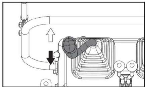
natural_image
Technical diagram of a mechanical assembly with no visible text or symbols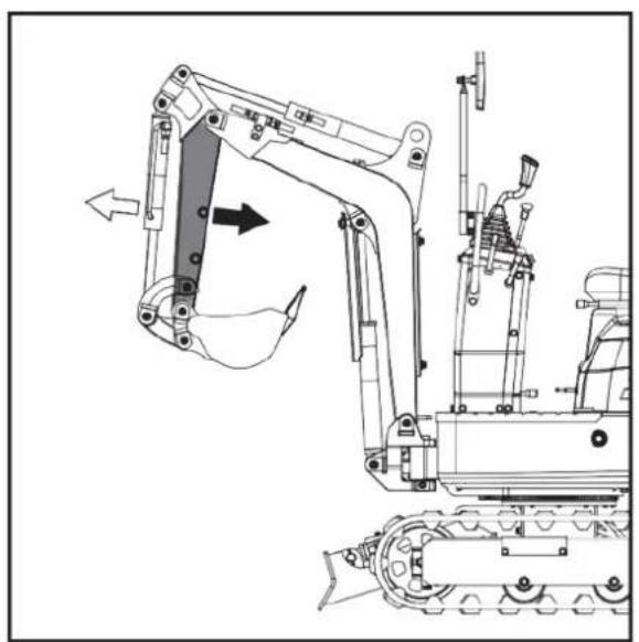
natural_image
Technical line drawing of a mechanical excavator assembly (no text or symbols)OPERATION OF BUCKET
To dig with the bucket, move the right attachment control lever from the neutral position towards the left. Moving the control lever towards the right pushes the bucket outwards and dumps its contents.
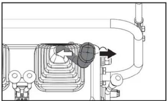
natural_image
Technical diagram of a piping system with valve and valve components (no text or labels)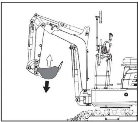
natural_image
Technical line drawing of an excavator with a downward load arrow, showing mechanical components and structural details (no text or symbols)- When working in groups, always let the others know what you are going to do before you do it.
- Keep away from the working area.

IMPORTANT!
- Do not operate the left attachment control lever abruptly from the right to the left (or vice versa). Because of the law of inertia, this causes an impact load on the swing gear and the swing motor. Additionally, the lifetime of the machine will be shortened.
-
Unlock the swing lock pin before carrying out swivel operations.
-
Tilt the control lever to the left and the upper structure will turn to the left.
- Tilt the control lever to the right and the upper structure will turn to the right.
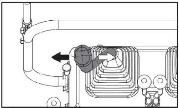
natural_image
Technical diagram of a mechanical or electrical component with pipes and valves, no visible text or symbols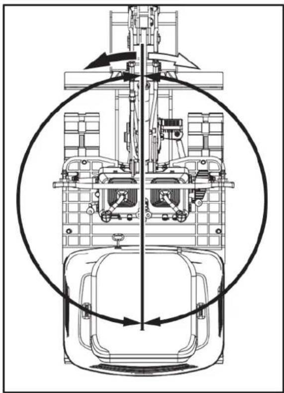
natural_image
Technical line drawing of a mechanical assembly with no visible text or symbols- Step on the front of the pedal to swing the boom to the left.
- Step on the rear of the pedal to swing the boom to the right.

text_image
Technical diagram of a mechanical assembly with labeled parts A, B, and numbered components 1 and 21 - Pedal. 2 - FRONT
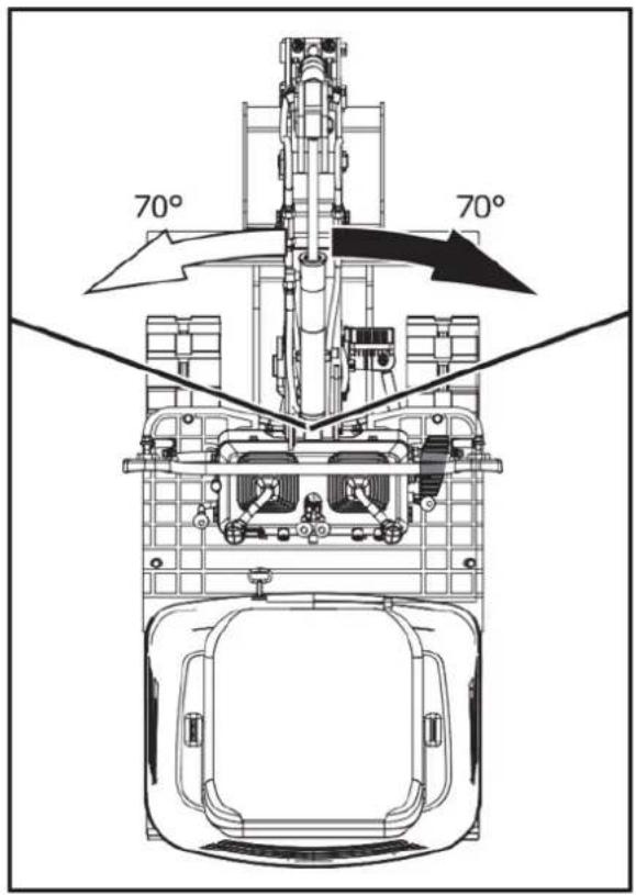
text_image
70° 70°BOOM SWING PEDAL

WARNING! Always keep your toes within the edge of foot step; otherwise there is a possibility that your toes will be caught between swing frame and boom or boom cylinder.

CAUTION! When boom swing operation is not in use, fold the boom swing pedal forward to fix the pedal from unexpected moves.
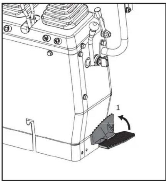
natural_image
Technical line drawing of a mechanical assembly with no visible text or symbols- Fix
OPERATION OF DOZER
- To lift the dozer, pull control lever for dozer backward. Push the control lever forward to lower the dozer.
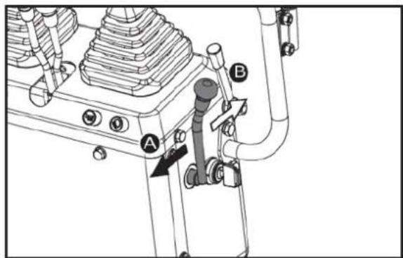
text_image
Technical diagram of a mechanical assembly with labeled parts A, B, and C, showing components like bolts, valves, and tubing.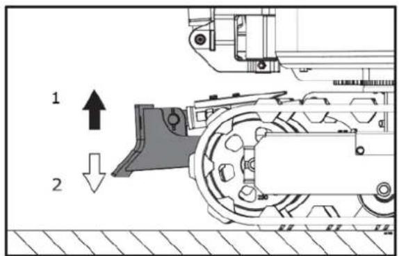
text_image
1 2-
Raise. 2. Lower
-
While undertaking earth moving work, control both drive levers with the left hand and the control lever for dozer with the right hand.
DRIVING

WARNING!
- Before starting the engine, make sure that no further persons are in the machine surroundings.
- Before operating the machine, check the crawler direction. (Idler and dozer to the front of the machine).
- Avoid travelling across a slope or working sideways on a slope.
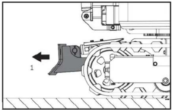
natural_image
Technical diagram of a mechanical assembly with labeled component '1' (no text or symbols beyond label)-
Front
-
Adjust the engine speed from idling to an intermediate speed.
- Raise the dozer and hold the bucket about 20 to 40 cm off the ground.
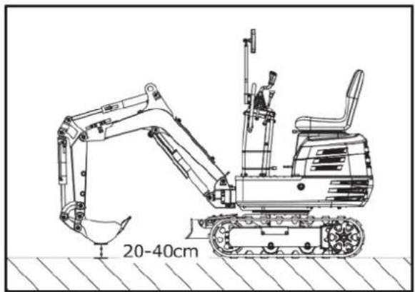
text_image
20-40cmDrive Levers (Right, Left)

WARNING! If the swing frame has been turned 180, i.e. the dozer is, seen by the operator, "behind", then the travel direction is opposite to the drive direction of the levers (when activating the drive lever forwards, the machine, seen by the operator, will move backwards).
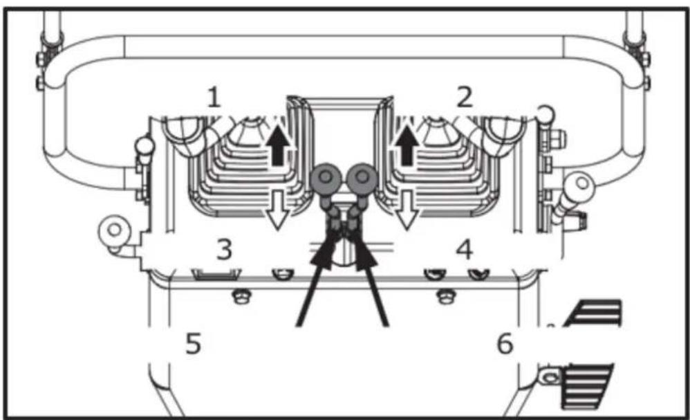
text_image
Technical diagram of a mechanical or electrical device with numbered components and directional arrows indicating flow or movement.- Forward. 2. Forward. 3. Backward. 4. Backward. 5. Left drive lever. 6. Right drive lever
Pushing both drive control levers forward simultaneously, moves the machine forward. Similarly, pulling both drive control levers backward simultaneously, moves the machine backward. The front of the machine is the direction where the dozer is present.
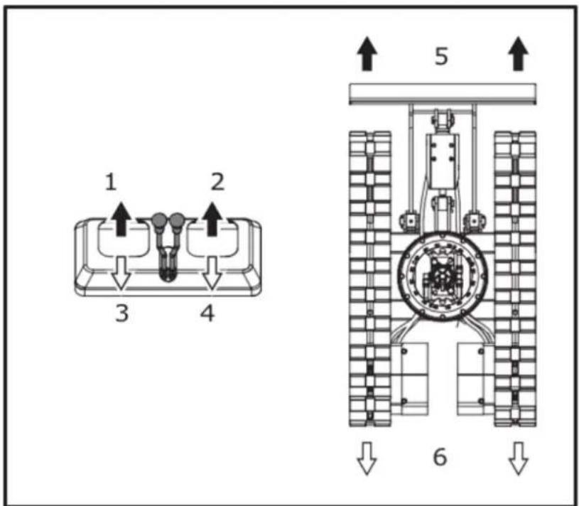
text_image
1 2 3 4 5 6- Forward. 2. Forward. 3. Backward. 4. Backward. 5. Forward. 6. Backward

IMPORTANT! If the crawler is clogged with sand or gravel while working on soft ground, lift up one crawler with the help of the boom, arm and bucket and let the crawler rotate to shake off the sand and gravel.
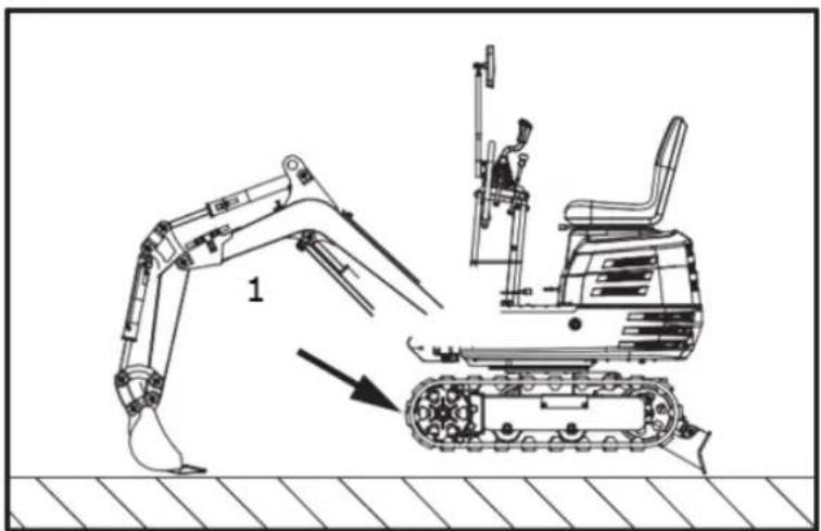
natural_image
Technical line drawing of an excavator and tracked vehicle on a construction ground (no text or symbols)- Rotate to shake off and gravel

IMPORTANT! When driving in the muddy ground, if the machine is stuck in the mud and cannot move, it should be lifted to a safety zone with the hoisting belt as shown in the drawing below.
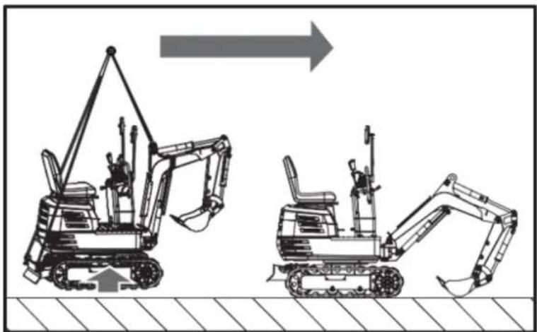
natural_image
Two excavators in action poses, one lifting a boom and the other bending forward (no text or symbols)
IMPORTANT! The machine cannot travel on the muddy road with the slewing platform perpendicular to the tracks, so as to prevent the tracks from being involved in the mud.
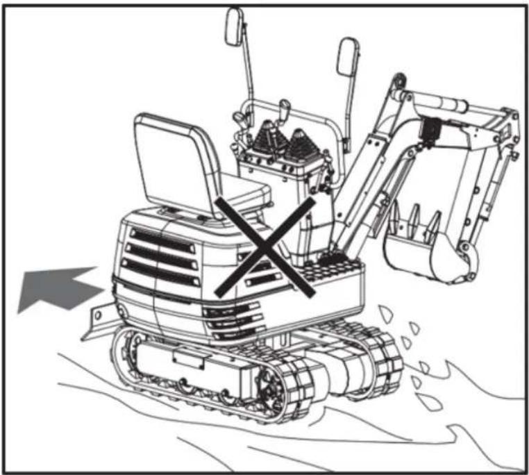
natural_image
Line drawing of a bulldozer with a cross mark indicating failure, no text or symbols presentTURNS

CAUTION!
• Do not change direction on steep slopes, or the machine could tip over.
• Before changing direction, beware of persons in the working area.
Pivot Turn
NOTE Movement as illustrated shows turning motion with the dozer positioned facing the front.
When the dozer is facing the back, the turning direction is reversed.
(For example, push the left (right) drive lever forward; right (left) crawler, seen by the operator, will move backward from the operator.)
Change of Direction while Stationary
- Push the left drive lever forward; the machine will turn to the right.
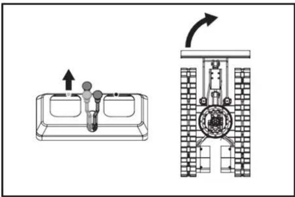
natural_image
Technical diagram showing a mechanical assembly with an upward arrow and a side-view view of a vehicle wheel (no text or symbols present)- Pull the left drive lever backward, back of the machine will turn to the right.
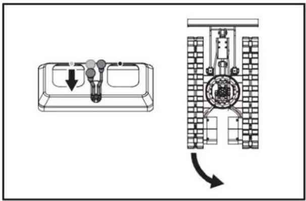
text_image
Technical diagram showing a device with internal components and a mechanical assembly with directional arrows indicating motion or transformation.Change of Direction while Travelling
- While travelling forward, pull back the left drive lever into the neutral position, and keep pushing the right lever in the forward position, the machine will turn to the left.
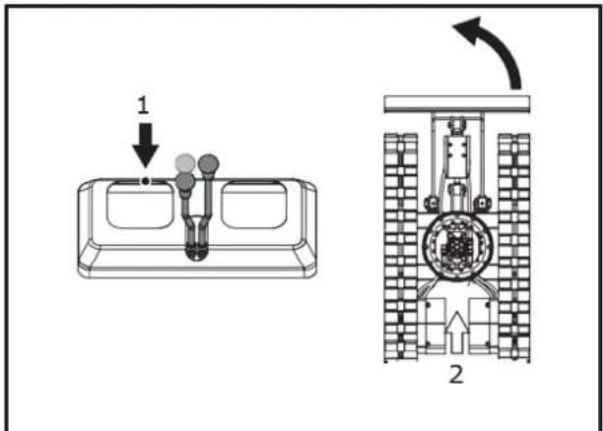
text_image
Technical diagram showing a device with labeled components and a mechanical assembly with directional arrows.-
Neural position. 2. Travelling forward.
-
While travelling backward, push back the left drive lever into the neutral position, and keep pulling the right lever in the backward position, back of the machine will turn to the right.
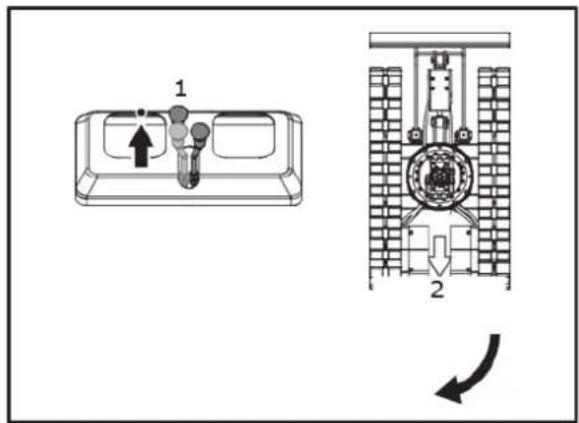
text_image
Technical diagram showing a device with labeled components and a schematic view of its internal structure.- Neural position. 2. Travelling backward.
Pivot Turn
When both drive levers are activated in the opposite directions, both crawlers will rotate with the same speed but in opposite directions, the machine will rotate in place. Centre of rotation is the centre of the machine.
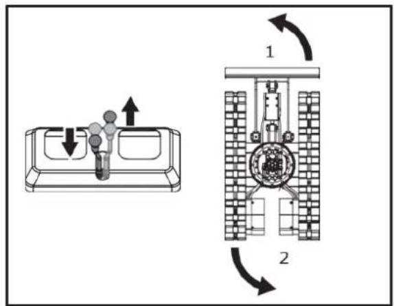
text_image
Diagram showing a device with directional arrows and a mechanical assembly, labeled with components 1 and 2.- Left spin turn. 2. Left spin turn.
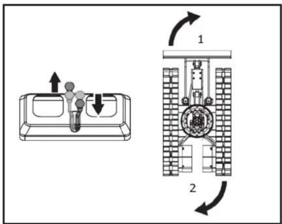
text_image
Diagram showing airflow or mechanical system with labeled components and directional arrows, including a device component and a circular component.- Right spin turn. 2. Right spin turn.
UP AND DOWNHILL TRAVELLING
While travelling uphill, keep the lower edge of the bucket approx. 20 to 40cm above the ground. Although the machine will not slip easily because of the crawlers, it is safer to let the bucket slide over the ground while travelling downhill. Always choose slow speed for uphill and downhill travelling.
[UPHILL TRAVELLING]
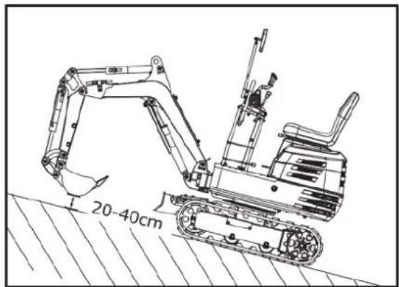
text_image
20-40cm[DOWNHILL TRAVELLING]
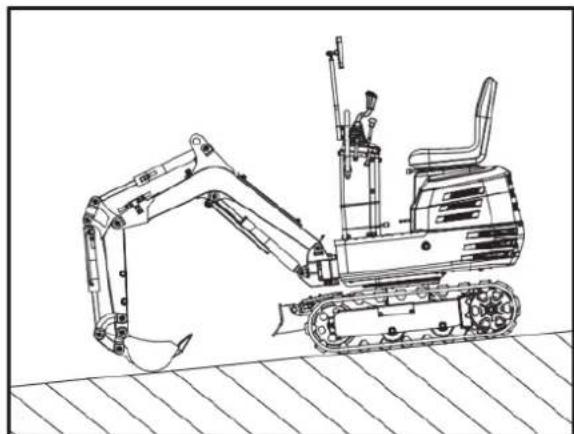
natural_image
Line drawing of an excavator on a construction ground (no text or symbols)PARKING ON A SLOPE

WARNING! When the machine is parked or left unattended on a slope, be sure to put the bucket on the ground and place all control levers in neutral position, then brace the crawlers with chocks.
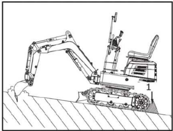
natural_image
Technical line drawing of an excavator on a sloped terrain (no text or symbols)- Chock
IMPORTANT INFORMATION ON MACHINE OPERATION

CAUTION!
• After work, clean the machine and lubricate all movable parts.
- Check oil level.

IMPORTANT!
-
Do not try to crush concrete or boulders using side swings with the bucket. Also avoid using side sweeps of the bucket to move earth piles.
• Under all circumstances avoid the following operations: -
Excavation using the gravitational impact of the machine.
- Compacting of gravel or soil using the dropping action of the bucket.
-
Excavation using the travelling power of the machine.
-
Do not try to drop or shake of soil adhering to the bucket in the manner shown in the explanation below. This can cause damage to the machine.
- Adhering soil can be shaken off when the bucket is being emptied by moving the bucket out to the maximum stroke of the cylinder. Should this not suffice, swing out the arm as far as possible and operate the bucket back and forth.
- Do not hit the dozer with the boom cylinder! Make sure that the boom cylinder does not hit the dozer when carrying out deep excavation. If necessary swivel the upper structure so that the dozer is at the back of the machine.
- Pay attention when pulling in the bucket! When pulling in the bucket (for driving or transportation) avoid hitting the dozer.
- Avoid collisions!
- When moving the machine, pay attention so that the dozer does not collide with obstructions such as boulders etc.
• Such collisions substantially shorten the life span of the dozer and the cylinder.
• Support the machine correctly!
- When stabilizing the machine with the dozer, lower the whole dozer fully on to the ground.
- If the water or mud level reaches higher than the top of the tracks, the swivel bearing, swivel motor gear and ring gear may be exposed to mud, water and other foreign objects.
• The machine must be properly pressure washed after each use.
- Thoroughly clean the area around the swivel bearing, swivel motor gear and ring gear to remove foreign objects.
- Refer to operator's manual for proper swivel bearing, swivel motor gear and ring gear lubrication procedures.
- Reinstall any protective covering if removed earlier.
TRANSPORTING THE MACHINE ON A TRUCK

DANGER!
- No directional changes should be made when the machine is on the ramp. Should a change of direction be necessary, drive off the ramp completely and make the turn.
- When driving forwards or backwards onto the truck, or when swinging the upper body, make sure that neither the cabin or the gates of the truck will be damaged.
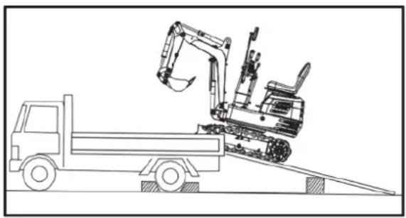
natural_image
Line drawing of an excavator on a flatbed truck, no text or symbols present
DANGER!
- When the machine reaches the point between the ramps and the truck bed, halt and then move very slowly until the machine reaches the horizontal position.
- Move the machine onto the truck only with the arm completely pulled in. Otherwise the truck cabin could be damaged when swinging the upper body around.
- Do not jack up the machine using its boom to load or unload the machine from the truck. Dangerous situation could arise.
Transporting on a Truck

WARNING! After loading the machine on the truck, lower the bucket and dozer onto the truck bed. Lock the swing frame with the swing lock pin.
Prepare a platform to load or unload the machine. Take following steps when using ramps.
- Apply the parking brakes of the truck, and block the drive wheels from both sides.
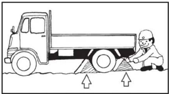
natural_image
Illustration of a worker using a flatbed truck to lift or lift a slope, with upward arrows indicating the load (no text or symbols present)- Use fixing plates to secure the ramp properly. Connect the ramps directly with the truck bed.
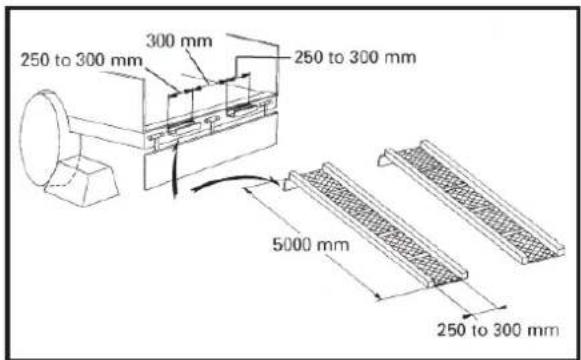
text_image
250 to 300 mm 300 mm 250 to 300 mm 5000 mm 250 to 300 mm- For additional safety, use blocks or struts under the ramps and the truck bed.
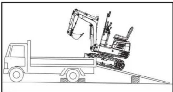
natural_image
Line drawing of a construction vehicle with an excavator on an inclined ramp (no text or symbols)-
Completely align the ramps and the crawlers and then drive the machine slowly up the ramps with the dozer in the front. After ensuring that the crawlers are completely on the truck bed, swivel the upper body around to the back of the truck.
-
Lock the swing frame with the swing lock pin.
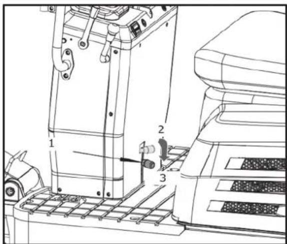
text_image
Technical diagram of a machine tool with numbered components and labeled parts-
Swing lock pin. 2. Unlock. 3. Lock.
-
Lower the bucket and dozer onto the truck bed and then lock the boom with the lever before getting off.
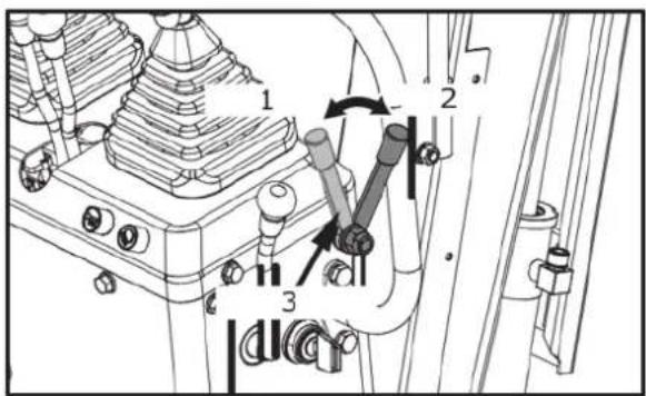
text_image
Technical diagram of a mechanical assembly with numbered components and directional arrows indicating motion or movement.-
Unlock. 2. Lock. 3. Lock lever.
-
Block the crawlers and tie down the machine.

natural_image
Cartoon illustration of a truck with an excavator and a bucket, no text or symbols present- Before unloading, remove the swing lock pin and then raise the dozer and bucket from the truck bed.
LIFTING OF THE MACHINE

DANGER! The correct instructions for safe handling are described here. Read these carefully before moving the machine. Make sure that the operating personnel read the operator's manual carefully.
Basics when Lifting with Chains / Straps
- The lifting and crane operation is to be undertaken according to the guidelines described.
- As the accessories for lifting mentioned in this instruction are only given as reference, the standards concerning strength, control and other details are based on the respective applicable guidelines.
Safety Aspects when Lifting with Chains / Straps
- Do not lift loads that exceed the maximum load capacity of the crane.
- Choose correct tackle suitable to the weight, size and form of the load.
- First assess the centre of gravity of the load, position the hook directly over the load and lift the load so that the centre of gravity of the load lies as low as possible.
- The steel wires must be fixed in the middle of the hook.
- The load must be lifted vertically from the ground.
- Do not enter the working area under suspended loads and do not move the load over other persons. The load must be moved in an area where the equilibrium can be balanced out easily.
General guidelines for lifting

WARNING! Do not lift the machine other than at the 3 points as illustrated.
- Lifting position. (see below illustration)
(1) Pull in the boom completely towards rear.
(2) Pull in the arm completely.
(3) Pull in the bucket completely.
(4) Swing the boom in the central position.
(5) Swing the upper body 180^ to make sure the dozer is seen from the operator behind.
(6) Insert the swing lock pin.
- Attaching the chains / straps.
(1) Always hook the machine at three points. (one on the boom and right and left of the dozer blade)

WARNING! The dozer must be raised.
(2) Always use a shackle on each lifting hole when attaching the straps.
(3) Use cushioning material at all places where the straps contact the machine.
3. Tackle
Choose components with enough strength.
4. Lifting
(1) Lift slowly and safely
(2) Do not enter the machine area when lifting.
(3) Lift the machine horizontally. (Modify connections according to needs)

natural_image
Technical line drawing of an excavator with labeled components (no text or symbols present)- Shackle
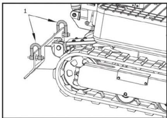
natural_image
Technical line drawing of a mechanical assembly with rollers and guide rails (no text or symbols)- Shackle
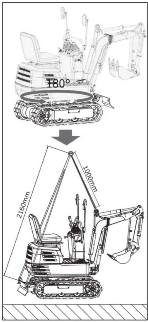
text_image
180° 2160mm 1000mmMAINTENANCE
MAINTENANCE INTERVALS
| No. | Check points | Intervals | Hour meter indicator | Consequently | Ref. page | |||||||||||||
| 50 | 100 | 150 | 200 | 250 | 300 | 350 | 400 | 450 | 500 | 550 | 600 | 1000 | 2000 | |||||
| 1. | Fuel | Check | Daily check | 41 | ||||||||||||||
| 2. | Engine oil | Check | Daily check | 42 | ||||||||||||||
| Change | ○ | ○ | ○ | ○ | ○ | ○ | ○ | ○ | ○ | ○ | ○ | ○ | ○ | ○ | every 50 hrs | 45 | ||
| 3. | Hydraulic oil | Check | Daily check | 43 | ||||||||||||||
| Change | ○ | ○ | every 1000 hrs | |||||||||||||||
| 4. | Lubrication points | Check | Daily check | 43 | ||||||||||||||
| 5. | Cooling Fan | Check | Daily check | 44 | ||||||||||||||
| 6. | Electrical lines | Check | Daily check | 45 | ||||||||||||||
| 7. | Air Cylinder / Cooling fin | Clean | Daily check | 45 | ||||||||||||||
| 8. | The Whole Machine | Clean | Daily check | 45 | ||||||||||||||
| 9. | Battery condition | Check | ○ | ○ | ○ | ○ | ○ | ○ | ○ | ○ | ○ | ○ | ○ | ○ | ○ | ○ | every 50 hrs | 46 |
| 10. | Greasing of swing bearing teeth | Check | ○ | ○ | ○ | ○ | ○ | ○ | ○ | ○ | ○ | ○ | ○ | ○ | ○ | ○ | every 50 hrs | 47 |
| 11. | *Air filter element | Clean | ○ | ○ | ○ | ○ | ○ | ○ | ○ | ○ | ○ | ○ | ○ | ○ | ○ | ○ | every 50 hrs | 48 |
| Change | ○ | ○ | ○ | ○ | ○ | every 200 hrs | 50 | |||||||||||
| 12. | Greasing of swing ball bearings | Check | ○ | ○ | ○ | ○ | ○ | ○ | ○ | ○ | every 100 hrs | 50 | ||||||
| 13.. | Fuel pipes and hoses | Check | ○ | ○ | ○ | ○ | ○ | every 200 hrs | 50 | |||||||||
| Change | every 2 years | 52 | ||||||||||||||||
| 14. | Hydraulic return filter element | Change | ○ | ○ | every 1000 hrs | 51 | ||||||||||||
| 15. | Hydraulic suction filter element | Change | ○ | ○ | every 1000 hrs | 51 | ||||||||||||
| 16. | Spark Plug | Check | ○ | ○ | ○ | ○ | ○ | ○ | ○ | ○ | ○ | ○ | ○ | ○ | ○ | ○ | every 50 hrs | 49 |
| Change | ○ | ○ | ○ | every 500 hrs | 52 | |||||||||||||
* Clean the air filter more frequently if used in dusty conditions.
OPENING AND CLOSING OF PARTS
Opening/Closing of the Engine Hood

CAUTION!
• Do not open the engine hood before stopping engine.
• Do not touch the exhaust muffler or the exhaust pipe; serious burns can occur.
Turn the key in the direction indicated by the arrow as shown in the below Figure to open the engine hood.
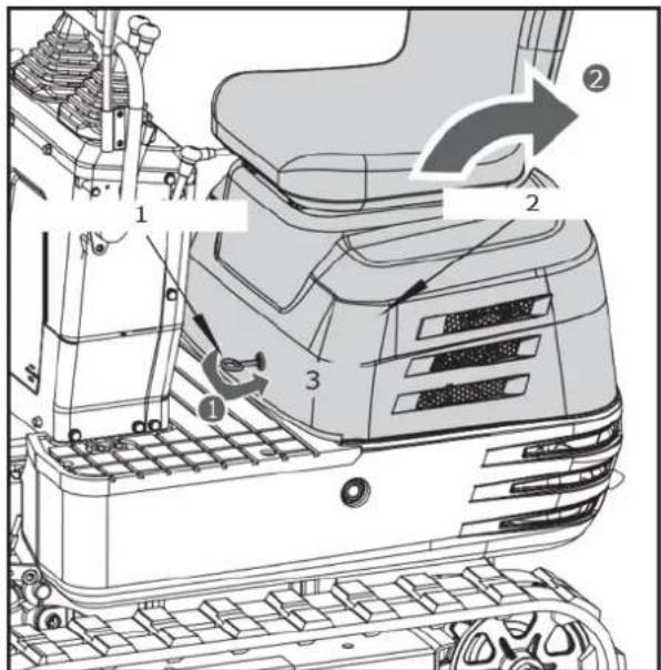
text_image
Technical diagram of a tracked vehicle with numbered components and directional arrows indicating motion or movement.- Engine Hood Key. 2. Engine Hood. 3. Open.
Keep the Tools and Operator's Manual in the Manual Tube
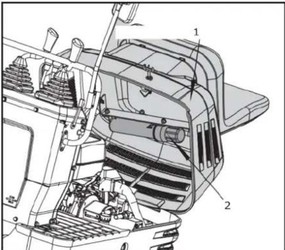
text_image
Technical diagram of a vehicle engine showing labeled components and structural parts- Operator's seat & Engine hood. 2. Manual Tube.
DAILY CHECKS
For your own safety and to assure the long-life span of your machine, a careful check should be made before each operation.
Check Fuel Level

CAUTION!
- Stop the engine before fuelling. - Do not smoke while fuelling.

IMPORTANT! Use unleaded gasoline with a pump octane rating of 86 or higher.
-
Check the fuel level in fuel tank.
-
Open the tank cap, and fill with fuel.
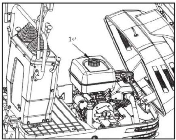
natural_image
Technical line drawing of a vehicle engine bay with visible components and no text or symbols- Tank cap
Fuel tank capacity: 6L

IMPORTANT!
• Always fill up fuel after a day's work.
• See "PURGING OF THE FUEL SYSTEM" in "OTHER ADJUSTMENTS AND REPLACEMENTS".
- Fuel tank cap has an air breather. Make sure to clean the air breather when filling up with fuel.
If the air breather is clogged with mud, the fuel tank becomes under-pressurized.
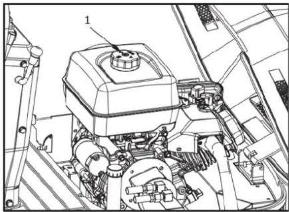
natural_image
Technical line drawing of a mechanical assembly with labeled component (no text or symbols present)- Air breather
Draining the Water or Air from the Fuel Tank

DANGER! When draining water or air from the fuel, always keep away from flames.
If the gasoline engine is not used for a long time, the problem that the engine cannot be started may occur when the engine is just started. The following operations are required:
- Close the fuel tank switch.
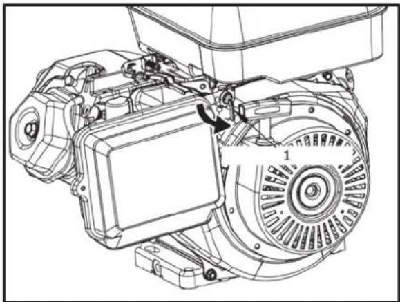
natural_image
Technical line drawing of an electric motor assembly with labeled components (no text or symbols present)-
Fuel Tank Switch
-
Unscrew the bolt at the carburettor vent port to drain the water or gas from the fuel.
- Close the bolt at the carburettor vent.
- Turn on the fuel tank switch.
- Start the engine.
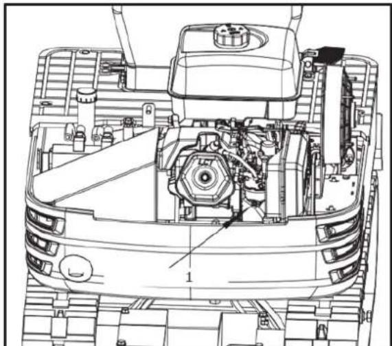
natural_image
Technical line drawing of a tank interior showing engine, chassis, and structural components (no text or labels)- Carburettor Vent
Check Engine Oil Level

CAUTION! Stop the engine before checking the oil level.
Insert the oil gauge rod fully into the prepared opening, remove again and check the oil level; if necessary fill with oil. The machine must be on level ground when checking the oil level.
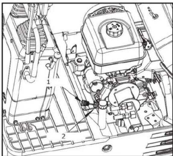
text_image
Technical diagram of a vehicle engine bay with numbered components and labeled parts- Oil gauge. 2. Filling port.

IMPORTANT!
• Use engine oil with the correct viscosity. (according to the outside temperature).
- After stopping the engine, wait five minutes, then check oil level. (Machine must be on level ground.)
Check Hydraulic Oil Level

CAUTION! First lower all attachments on the ground then stop the engine.

IMPORTANT!
- Before filling with oil, wipe away all sand and dust from around the oil port. Make sure you use an identical type of hydraulic fluid.
-
The machine has been filled with hydraulic fluid before delivery. See "RECOMMENDED OILS". (Do not mix different makes!)
-
Move the machine on to level ground. Extend every cylinder rod up to its centre position, place the bucket in contact with the ground.
- Check the oil level as to whether it lies on the centre mark under normal temperature 10 to 30 C.
- Enough oil is present if the oil level lies between the markings.
- Should the oil level be too low, add enough oil through the oil port before starting the engine. This step is important for the protection of the hydraulic system.
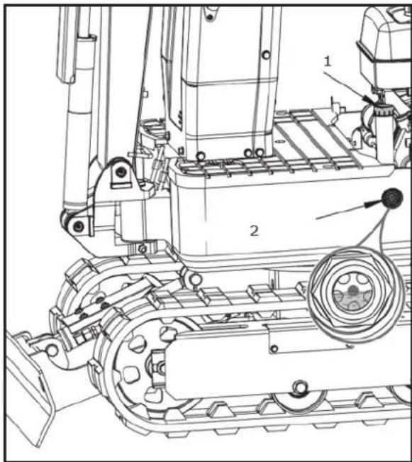
text_image
Technical diagram of a tracked vehicle with labeled components and parts- Tank cap. 2. Specified oil level.
Lubrication Points

CAUTION!
• First lower all attachments on the ground then stop the engine.
• While greasing, take care not to step on the bucket teeth.
- When doing excavation work in water, generously grease the following points. After finishing work, grease again.
Grease the marked grease nipples shown by arrows in the illustration below:
- Boom bottom linkage 1 place
-
Arm bottom linkage 1 place
-
Boom cylinder boss 2 places
- Arm cylinder boss 2 places
- Bucket cylinder pin 2 place
- Boom swing fulcrum 1 places
- Wing cylinder boss 2 place
- Dozer linkage pin 2 places
- Bucket link pin 5 places
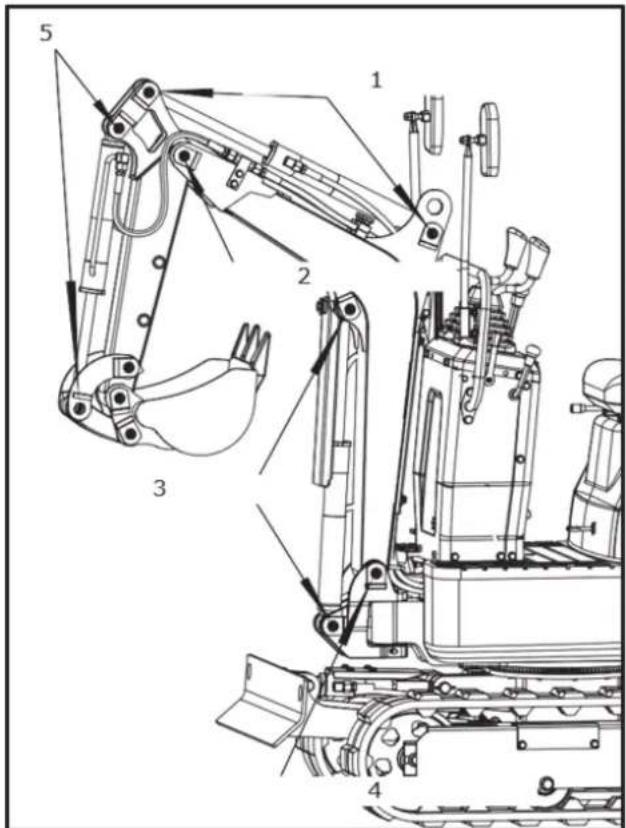
text_image
Technical diagram of an excavator with labeled parts including arm, bucket, and guide components- Arm cylinder boss (×2). 2. Arm bottom linkage (×1). 3. Boom cylinder boss (×2). 4. Boom cylinder linkage (×1). 5. Bucket cylinder pin (×1).
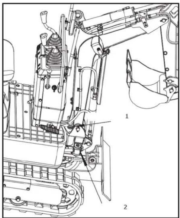
natural_image
Technical line drawing of a mechanical assembly with labeled parts (no text or symbols present)- Boom swing fulcrum ( × 1). 2. Wing cylinder boss ( × 2).
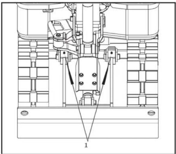
natural_image
Technical line drawing of a mechanical assembly with no visible text or symbols- Dozer linkage pin (x2)
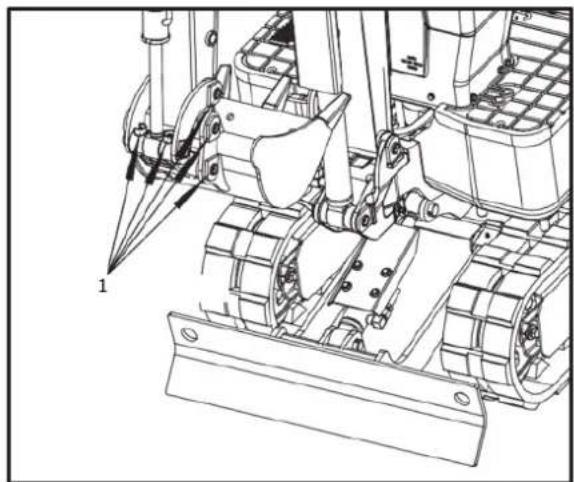
natural_image
Technical line drawing of a bulldozer with visible mechanical components and no text or symbols- Bucket link pin (x5)
Check Cooling Fan

CAUTION!
• Always stop the engine before checking the Cooling Fan.
- Wear eye protection w hen cleaning with compressed air.
- When the weather is hot, check the cooling fan more frequently whether the operation is normal; Check the dust on the cooling fan of the gasoline engine cylinder head. If there is a lot of dust, please use compressed air to clean it.
- Check whether the muffler chimney and muffler cover have oxidation. Check whether the insulation layer of muffler cover is complete.
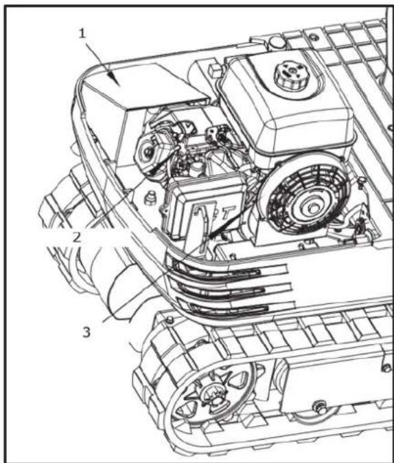
text_image
Technical diagram of a tracked vehicle showing labeled components including engine, motors, and wheel assembly- Muffler Cover. 2. Cylinder Head. 3. Cooling Fan.

IMPORTANT! Cooling fan must be clean in order not to overheat the engine and allow free flow of air through the system.
Cleaning of Engine and Electrical Wiring

CAUTION! Always stop the engine before cleaning the wiring, cables and engine.
Before starting, check whether flammable substances have gathered on the battery, the cables and wiring, the muffler or on the engine. Remove thoroughly.
Checking the Electrical Circuit
Check the electrical circuitry for disconnections, shorts or loose terminals.
Washing the Whole Machine

IMPORTANT! Do not wash the machine with the engine running. Water could enter the air filter and damage the engine. Make sure that the air filter is kept dry.
REGULAR CHECKS AND MAINTENANCE WORK
EVERY 50 SERVICE HOURS
Engine Oil Change

CAUTION! First stop the engine and wait long enough for the oil to cool down.
- Remove the drain plug on the underside of the engine and drain all oil.

IMPORTANT! Place a suitable container below the engine to catch the used oil. Dispose of used engine oil according to local laws. We suggest you take used oil in a sealed container to your local recycling centre or service station for reclamation.
- Re-tighten the drain plug.
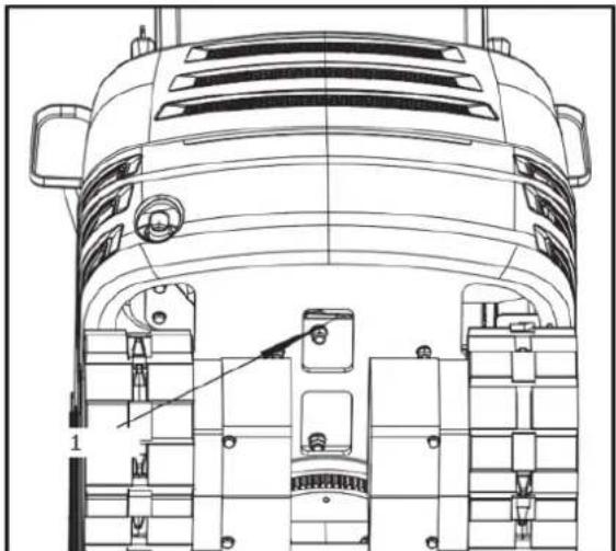
natural_image
Technical line drawing of a mechanical component with internal parts and mounting holes (no text or symbols)-
Drain plug
-
Fill with new oil up to the required level.
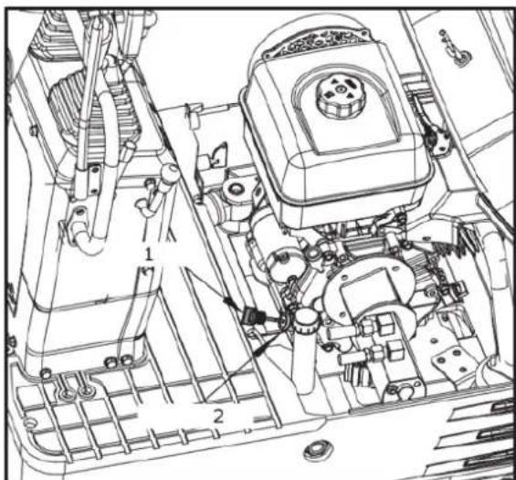
text_image
Technical diagram of a vehicle engine bay with numbered components and labeled parts-
Oil gauge. 2. Filling port.
-
Let the engine idle for approx. 5 min. Check the engine oil level. To check the engine oil level, insert the oil gauge completely into the respective port opening and pull out again. If the oil level lies between both markings, no oil must be added.

IMPORTANT! Regardless of the service hours, an engine oil change is due every 1 year.
Engine oil volumes: 1.1 L
Engine Oil Capacities:
306cc - 37.2 oz (1.1 liter)
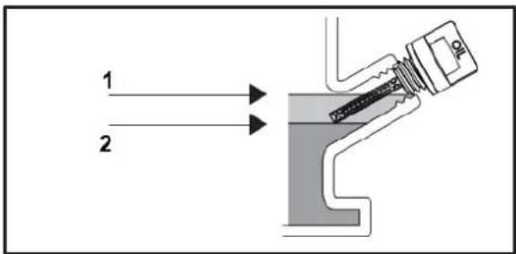
text_image
1 2- Max Upper Level. 2. Min Lower level.
Note: Total oil capacity could be as much as 4 additional ounces over volumes above due to engine mounting angle and proper draining.
NOTE Running the engine with a low oil level can cause engine damage.
Engine Oil Recommendations
Engine oil affects performance and service life. Use 4-stroke automotive detergent oil.
SAE 10W-30 is recommended for general use. Other viscosities shown in the chart may be used when the average temperature in your area warrants.
The SAE oil viscosity and service classification are in the API label on the oil container. Use API SERVICE category SJ engine oil, or higher.
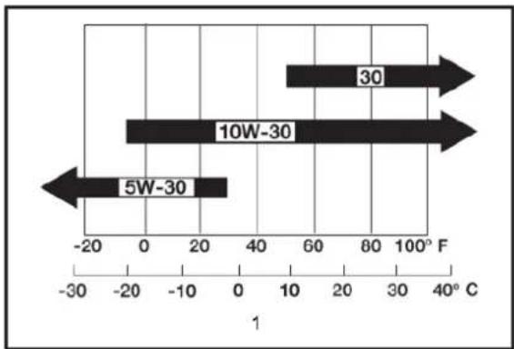
bar
| Range | Value | |---|---| | 5W-30 | -20 | | 10W-30 | -10 | | 30 | 60 |- AMBIENT TEMPERATURE
Battery Service

CAUTION!
- Batteries contain sulphuric acid which can cause severe burns. Avoid all contact with skin, eyes or clothing. Antidote - External: Rinse with plenty of water. Internal: Drink large quantities of water or milk.
- Call a physician immediately. Eyes: Rinse with plenty of water for 15 minutes and get prompt medical attention. Keep batteries out of the reach of children.
- Before inspection or dismounting the battery, be sure to turn of the engine and turn the starter switch to the "OFF" position.
-
When removing the battery, always disconnect the negative ground cable first. The reverse when installing a battery, always connect the ground cable last. This prevents a possible explosion caused by sparks.
• Always wear eye protection when working with the battery. -
Check whether the battery appearance is deformed.
- If the battery is deformed, replace it.
- Clean the battery cover (ventilation hole) without dust.
- Check whether the battery terminal connection is loose. If it is loose, retighten it. Pay attention to tightening the positive screw, and make sure that the tool that used do not touch the cover.

WARNING! Before tightening the positive screw, make sure to turn off the negative ground cable switch first.
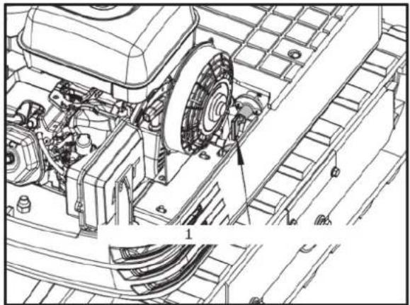
natural_image
Technical line drawing of a mechanical assembly with gears and components (no visible text or symbols)- Negative Ground Cable Switch
Battery Charging

CAUTION!
- When the battery is being activated, hydrogen and oxygen gases in the battery are extremely explosive. Keep open sparks and flames away from the battery at all times, especially when charging the battery.
-
When disconnecting the cable from the battery, start with the negative terminal first. When connecting the cable to the battery, start with the positive terminal first.
• Do not check battery charge by placing a metal object across the terminals. -
To slow charge the battery, connect the battery positive terminal to the charge positive terminal and the negative to the negative, then recharge in the standard fashion.
- A boost charge is only for emergencies. It will partially charge the battery at a high rate and in a short time.
When using a boost-charged battery, it is necessary to recharge the battery as early as possible.
Failure to do this will shorten the battery's service life.
- When exchanging an old battery for new one, use battery of equal specification.
Greasing of Swing Bearing Teeth
-
Fill with grease through the grease nipple (at the right end side).
-
Grease at each 90 (1.58 rad.) position of the swing frame.
-
Fill with approx. 50g of grease (approx. 20 pumps with the grease gun). Distribute the grease over the teeth.
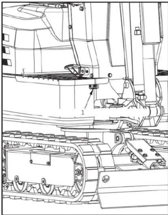
natural_image
Technical line drawing of a tracked vehicle with visible tracks and components (no text or symbols)- Grease nipple (for Bearing teeth)
Inspection and Cleaning of the Air Filter Element
Open the engine hood and remove the dustcover. Take out only outer element, clean the element, case interior and reassemble. During reassembly, take care to install the dust-cover so that its TOP mark (arrow) faces upwards. Do not remove the inner element.

IMPORTANT!
- Should the machine be used in extremely dusty areas, the air filter element must be inspected and cleaned more frequently than in the specified maintenance periods.
• The air filter has a dry element, keep free from oil.
• Do not run the engine without the air filter.
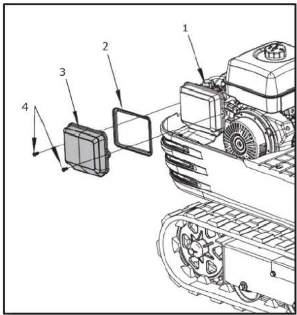
text_image
Technical diagram of a tracked vehicle with numbered components and directional arrows indicating assembly or movement.- Air Filter Seat. 2. Air Filter Element. 3. Air Filter Cover. 4. Fixing Bolt
Air Filter Maintenance

CAUTION! Wear eye protection.
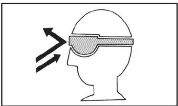
natural_image
Silhouette of a human head with an optical device emitting beams, no text or symbols presentCleaning with compressed air
Pressure of compressed air must be under 205 kPa (2.1 kgf/cm), and the cartridge should be blown clean from the inside to the outside until the dust deposits are completely clear.
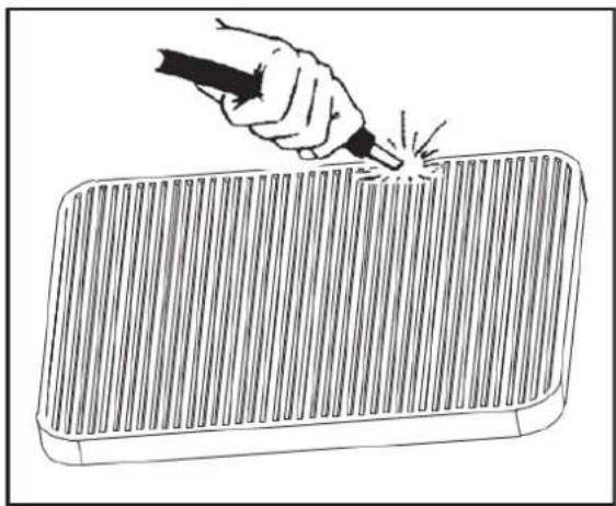
natural_image
Line drawing of a hand using a tool to mark a bright spot on a rectangular grating (no text or symbols)
IMPORTANT! If the air suction is still inadequate, or the colour of the exhaust gases is abnormal even after the cleaning, the air filter element must be replaced.
- Should the machine be used in extremely dusty areas, the air filter element must be inspected and cleaned more frequently than in the specified maintenance periods.
• The air filter has a dry element, keep free from oil.
• Do not run the engine without the air filter.
Checking Spark Plug
Use the special spark plug socket to remove the spark plug and check whether the ignition needle has carbon deposits. If yes, clean the carbon deposits. Replace if defective.
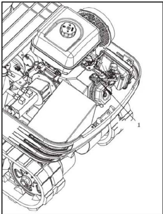
natural_image
Technical line drawing of a vehicle engine bay with internal components and no visible text or symbols1. Spark Plug
Spark Plug Service
- E6TC (Torch) and E6RTC (Torch) recommended for 79cc and 98cc engines only
- F6TC, F6RTC or F6RTP Torch) plug recommended
Cross References:
- Champion plug cross reference is: RN9YC (some tables show RN9YCC)
- NGK plug cross reference: BPR6ES
- BOSCH plug cross reference is: WR6DC

CAUTION! Using an incorrect spark plug may cause engine damage.
- When engine is cool, disconnect the spark plug cap and remove any debris from the spark plug area with high pressure air.
- Remove the spark plug with a 13/16-inch spark plug wrench.
- Inspect the spark plug. Replace it if the electrodes are worn or if the insulator is cracked or chipped. Spark plug gap should be set to 0.027 - 0.030 inches.
- Install the spark plug carefully to avoid cross threading. Screw in spark plug by hand until it stops turning.
- Tighten the spark plug with a 13/16-inch spark plug wrench. Tighten 1/4 turn after the spark plug seats.

CAUTION! A loose spark plug can overheat and damage the engine. Over-tightening the spark plug can damage the threads in the cylinder head.
- Attach the spark plug cap. Ensure spark plug cap snaps into place securely.
EVERY 100 SERVICE HOURS
Do all 50-hour servicing at the same time.
Greasing of the Swing Bearing
- Grease through the respective grease nipple.
- Grease at each 90^ (1.58 rad.) position of the swing frame.
- Using the grease gun, apply 5 shots at every position.
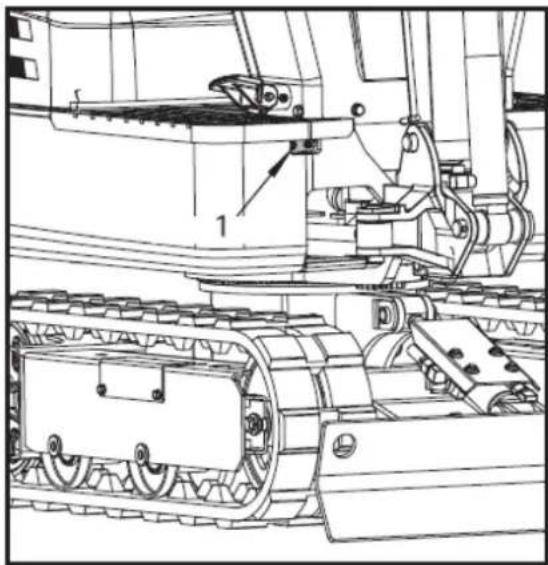
natural_image
Technical line drawing of a tracked vehicle with visible tracks and components (no text or symbols)- Grease nipple
EVERY 200 SERVICE HOURS
Do all 50 hour and 100 hour servicing at the same time.
Replacing Air Filter Element
Open the engine hood and remove the dustcover.
Remove and replace the outer element and inner element with new elements.
When reassembling, install the dust-cover so that its TOP mark (arrow) faces upwards.
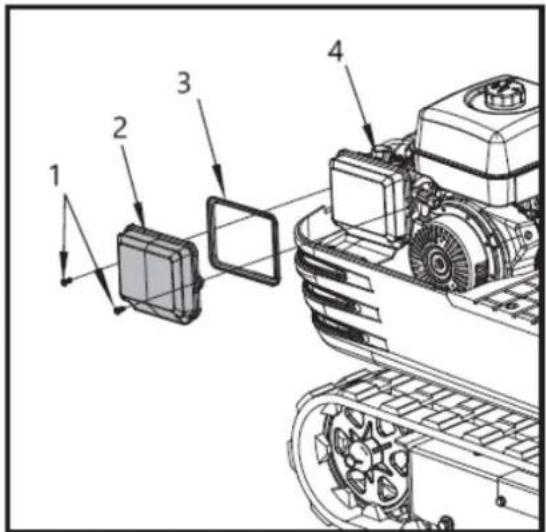
text_image
Technical diagram of a tracked vehicle with numbered components and directional arrows indicating motion or assembly.1- Fixing bolt
2- Air filter cover
3- Air filter element
4- Air filter seat

IMPORTANT! Shorten the replacement period if using in lots of dust or sandy areas
Checking Fuel Line
- Check to see that all lines and hose clamps are tight and not damaged.
- If hoses and clamps are found worn or damaged, replace or repair them at once.
EVERY 1000 SERVICE HOURS
Do all 50, 100, 200 and 500 hour servicing at the same time.
Hydraulic Oil Change (Including Replacing of the Suction Filter and the Return Filter in the Hydraulic Tank)
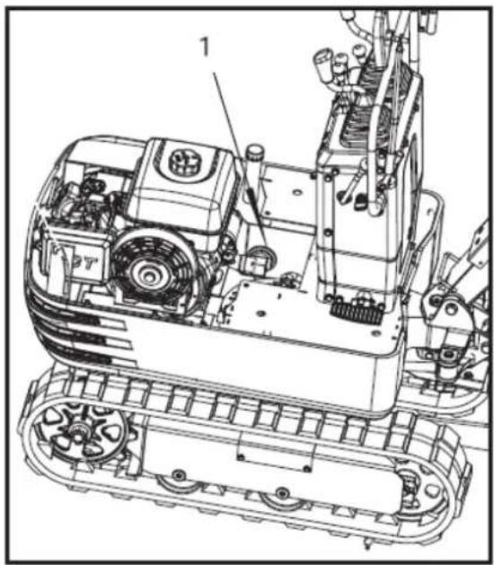
natural_image
Technical line drawing of a tracked robotic vehicle with visible engine and wheels (no text or symbols)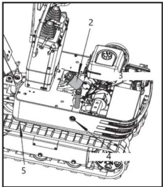
text_image
Technical diagram of a mechanical assembly with numbered components for identification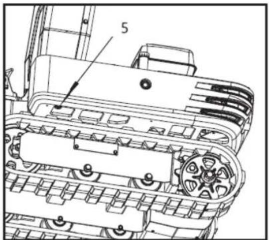
text_image
51- Suction filter
2- Return filter
3- Hydraulic oil filter
4- Hydraulic oil window
5- Drain plug
Check the oil window position of hydraulic oil. If it is lower than 1/3 of the oil window position, add oil.
| Hydraulic oil volumes | Hydraulic tank | approx. 10.8 L |
| Whole oil volumes | approx. 14.0 L |
Hydraulic Oil Check
- Changing and filling up of hydraulic oil
(1) Use only the recommended oils mentioned in the operator's manual when changing or topping up oil.
(2) When filling up oil, do not mix oils of different makes.
2. Changing the return filter and oil
(1) The filter must be changed more often because of contamination resulting from the frequent assembly and disassembly of the hoses.
(2) Use the correct replacement filter.
(3) Oil change according to operating hours.
| Hydraulic oil Return Filter | Suction Filter | |
| Normal machine work | every 1000 Hrs. | 1000 Hrs. |
ANNUAL SERVICING
Electrical Wiring and Fuses
Check the terminals periodically for proper connections. Loose wiring or damaged cables can cause improper functioning of the electrical system. Short circuiting, electrical leaks and other expensive problems could arise. Check wiring and replace damaged components immediately. If a fuse blows out soon after having been replaced, contact your nearest dealer. Never use a fuse other than specified.
Replacing Spark Plug
Do replacement after 1 year or 500 hours of use.
BIENNIAL SERVICING
Replacing Fuel Hose
Replace the hoses and clamps.
(See "Checking Fuel Line" every 200 hours maintenance.)
OTHER ADJUSTMENTS AND REPLACEMENTS
ADJUSTMENT OF CRAWLERS
To loosen the crawlers, follow the following procedure:

CAUTION! Do not crawl under the machine.
- Remove the side plate cover and loosen the nut M20 inside with a 30mm plum wrench.
- Adjust the hexagonal bolt M20x120 and rotate it clockwise to tighten the track; The track becomes loose when it rotates counterclockwise.
- After adjustment, fix the nut M20 with a plum spanner.
NOTE Tighten torque must be between 98 to 108 Nm (10 to 11 kgf-m).
- Install the side plate cover.

IMPROTANT!
• If the crawlers are too tight, wear is increased.
- If the crawlers are too loose, the crawler shoes may collide with the sprocket, and wear is increased. The crawler may dislocate or come off.
- Clean the crawler after every use.
- Should the crawler tension be heightened due to mud sticking, lift the crawler with the help of the boom, arm and bucket, idle the engine and remove the mud from the crawler, especially from the openings of the link plate, carefully.
Tension the crawlers as specified:
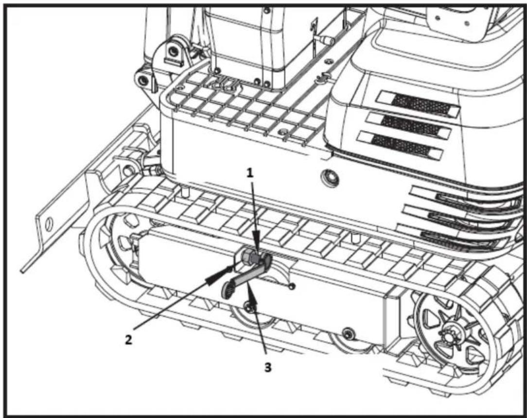
text_image
Technical diagram of a tracked vehicle with numbered components and labeled parts1-Bolt M20 × 120
2-Nut M20
3-30mm plum wench
- Tension the crawler in the lifted position, so that the distance (clearance between the track roller and the inside surface of the crawler) is 10 to 15 ~mm (see illustration), (In this case, the crawler seam is positioned on the top centre between the idler and the sprocket.

DANGER!
- Do not work under the machine in this condition.
- For your safety do not rely on hydraulically supported devices, they may leak down suddenly drop or be accidentally lowered.

natural_image
Technical line drawing of an excavator and tracked vehicle (no text or symbols)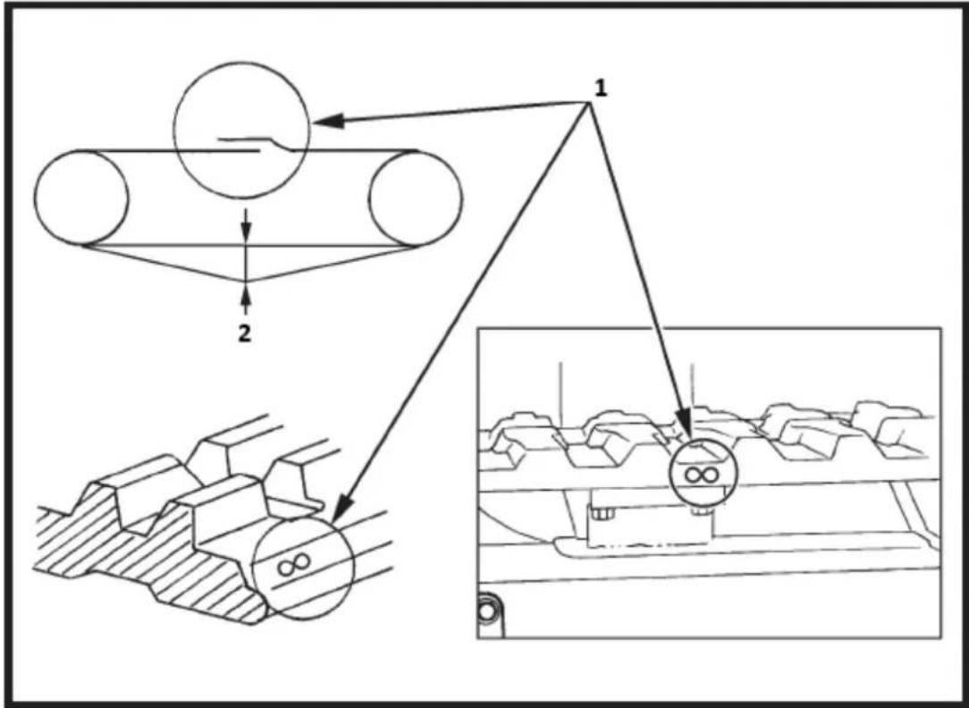
flowchart
graph TD
    A["Component 1"] --> B["Component 2"]
    B --> C["Output"]
    style A fill:#f9f,stroke:#333
    style B fill:#ccf,stroke:#333
    style C fill:#cfc,stroke:#333
- Seam (mark ∞)
- 10 to 15mm

IMPROTANT!
- Make sure that no obstacles, such as stones, are caught in the crawler. Remove such obstacles before adjusting the crawler tension.
- Crawler seam: The ends of the rubber crawler are joined with a seam. When adjusting the crawlers, the seam must be positioned on the top centre between the idler and the sprocket. If the seam is positioned incorrectly, the crawlers will be tensioned to loosely, and a further readjustment will be necessary.
- Rotate the crawler after adjustment one to two times to check the tension.
- Additionally the following points are to be observed when adjusting rubber crawlers.
(1) If the crawler slackens more than 0.98 in. (25 mm), readjust them.
(2) Check crawler tension 30 hours after initial use and readjust if necessary. Check and adjust thereafter every 50 service hours.
Special Information when Using Rubber Crawlers
- When turning, preferably make a slow swing turn. Avoid spin turns to lessen lug wear and ingress of dirt.
- If too much dirt and sand clog the crawlers. In this case move the machine for a short distance straight backwards to let the earth and sand fall off, then a turn can be made.
- Avoid using rubber crawler on riverbeds, stony underground, ferro-concrete and iron plates. The rubber can be damaged as well as crawler wear increasing.
CHANGING THE BUCKET

CAUTION!
- When the coupling pins are removed or installed, chips may come off. Always use gloves, goggles and a helmet.
- When the change of the equipment must be performed with the engine running, always work as a 2-person team.
• One person sits in the operator's seat and the other works on the machine. - Do not use your fingers to centre the holes, since they may be injured or even cut in case of sudden or uncontrolled movements.
- Read the manual of the attachment to do a correct operation safely when other attachments are installed.
FUSES
Replacing fuses
Slow blow fuse is provided to protect the electrical circuits. If the fusible link is blown, check the electrical circuits for problems and then replace with a new compatible slow blow fuse.
-
Remove the cover of the fuse box.
-
Replace the burn out fuse with the new fuse having the same capacity
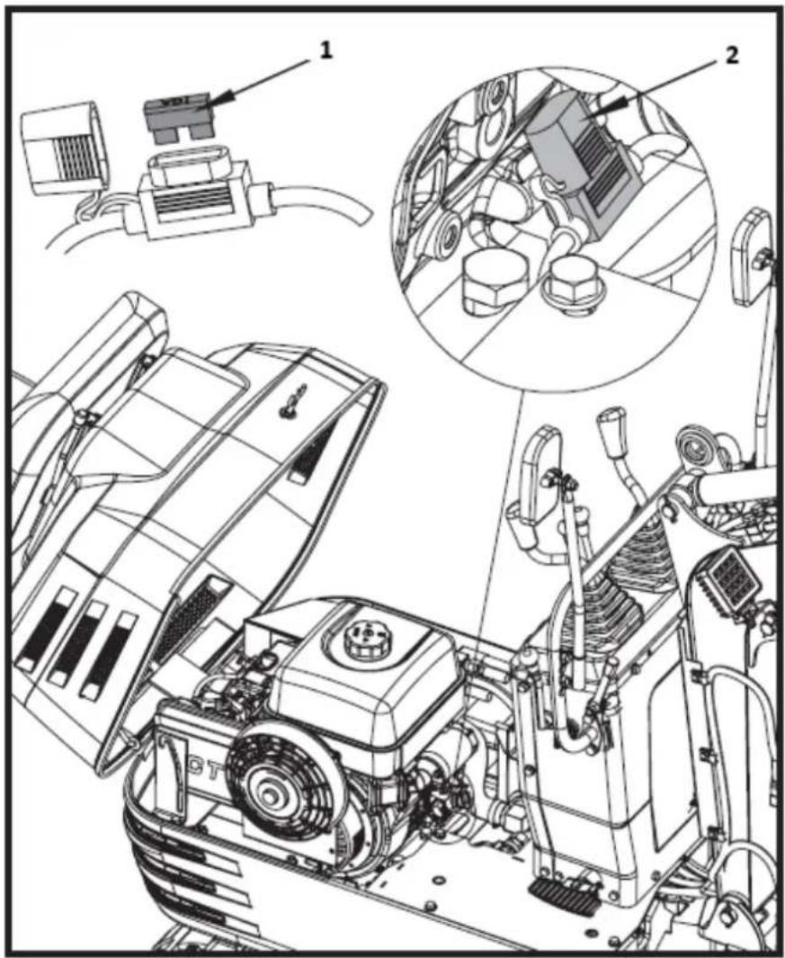
text_image
Technical diagram of an automotive engine with labeled components and exploded view1- Fuse
2- Fuse box
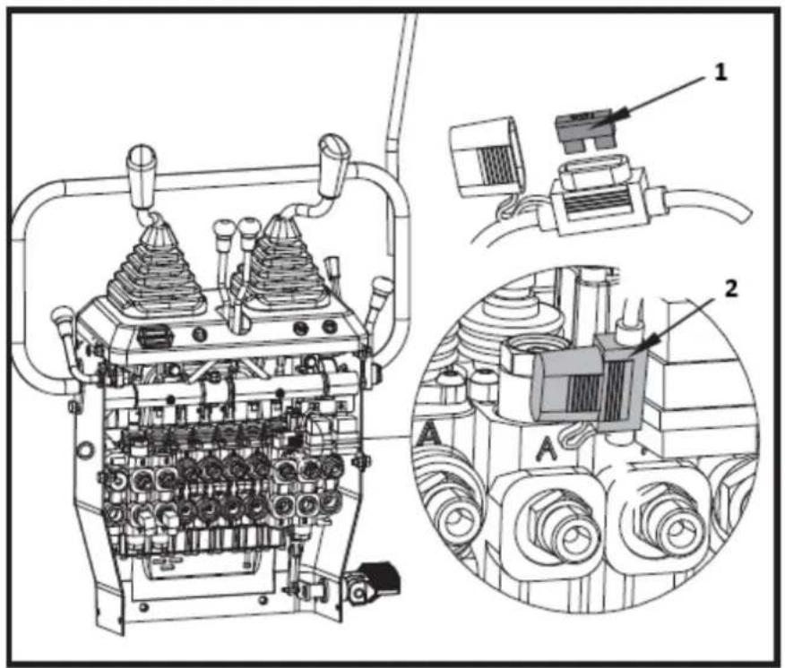
text_image
Technical diagram of a mechanical device with labeled components and exploded views1- Fuse
2- Fuse box
Fuse Capacities and Circuits
| No. | Capacity | Circuit |
| 1. 10A | Working relay fuse | |
| 2. | 10A | Working lamp, Horn, Hour meter fuse |
3.18. Troubleshooting
If the machine does not give the desired performance, or when problems arise, refer to the table below and take appropriate measures.
| Trouble | Cause | Countermeasure | |
| Starting difficulties | The fuel cock closed | Make sure that the fuel cock is in the "Open" position. | |
| Air or water in the fuel system | See the instruction in section " Draining the water or air from the fuel tank" to remove the water and air. | ||
| Oil viscosity is too high so that the engine funs sluggishly in winterBattery is almost dead; Starter motor doesn’t’ work | Use the engine oil for Winter use.Do recoil start to recharge the battery | ||
| Engine | |||
| The spark plug doesn't ignite. | Replace the spark plug | ||
| Low Engine oil level | Add the engine oil | ||
| Insufficient engine power | Low fuel level | Check fuel and add if necessary | |
| Clogged air cleaner | Clean the air filter element | ||
| Engine suddenly stops | Low fuel level | Check fuel and add if necessary purge the fuel system | |
| Abnormal exhaust gas colour | Poor fuel | Use high quality fuel | |
| Too much engine oil | Drain engine oil to prescribed oil level | ||
| Choke lever closes the choke valve in the carburettor | Open the choke valve | ||
| Hydraulic system | Boom, arm, bucket, drive, swing and dozer power is too low | Hydraulic oil level too low | Add oil |
| Leakages of hoses and / or joints | Replace hose or joint | ||
| Non- function of swing motor | Swing lock pin is in lock position | Remove swing lock pin in unlock position | |
| Drive system | Deviation of drive direction | Blocked through stones | Remove |
| Crawler too loose or too tight | Adjust accordingly | ||
3.19. OPERATION IN COLD WEATHER CONDITIONS
- Replace engine oil and hydraulic oil with those of viscosities suitable for cold weather.
- In cold weather, battery power drops, and the battery fluid may freeze if the battery is not sufficiently charged. To prevent the battery fluid from freezing, be sure to keep the battery charged at least 75% or more of its capacity after operation. To ease next starting, it is recommended to keep the battery stored in closed or heated rooms.
PROCEDURE AFTER WORK CARRIED OUT
Clean the machine thoroughly after work and wipe dry. Otherwise mud and earth on the crawlers could freeze if the temperature drops below the 0 C mark. Operation of the machine is then not possible. Store the machine in a dry place; if not possible, store on wooden planks or on mats. If the machine is kept on damp or muddy ground, the crawlers could freeze overnight. Operation of the machine is then not possible.
Additionally, the hydraulic cylinders piston rods must be rubbed dry. Otherwise severe damage could occur if dirty water seeps through the seals.
3.20. LONG STORAGE

Do not clean the machine with the engine running.
To avoid the danger of exhaust fume poisoning, do not operate the engine in a closed building without proper ventilation.
When storing, remove the key from the starter switch to avoid unauthorized persons from operating the machine and getting injured.
Should the Machine be Stored for a Longer Period of Time, Observe Following Procedures:
- The whole machine should be cleaned thoroughly and in all cases stored indoors. If the machine must be kept outdoors, lay out wooden planks on even ground, place the machine on the planks and cover completely.
- Do an oil change and grease the machine.
- Heavily grease the visible sections of the piston rods.
- Remove the battery and store indoors.

Wash the machine after stopping the engine.
If you wash the machine while running the engine, water may get into the air cleaner through the intakes causing engine problems.
Carefully, wash but do not splash water over the air cleaner.
Observe Following Procedures when the Machine is to be Operated after Long Storage.
- Wipe off the grease from the hydraulic cylinder rods.
- Turn on the engine and activate the attachments and the drive mechanisms without load in order to circulate the hydraulic oil. (If the machine is stored for longer than one month, undertake steps (1) and (2) once every month)
3.21. Periodic replacement of important component parts
To ensure safety in operation, you are strongly requested to inspect and service the machine at regular intervals. For added safety, ask your dealer to replace the following important component parts.
These parts are prone to degradation in material or subject to wear and tear with time. It is difficult to judge how much they have been affected at regular inspection. It is therefore necessary to replace them with new ones, whether wear is visible or not after a specified time of use.
If any of them is found worn even before the specified use, it must be repaired or replaced the same way as other parts.
If any of the hose clamps is found deformed or cracked, the hose clamp must also be replaced.
For the hydraulic hoses other than the ones to be replaced periodically, inspect them for the following points. If found unusual, tighten them up, replace them.
When replacing the hydraulic hoses, change their O rings and sealings with new ones.
For replacement of the important parts, contact your dealer.
At the following periodic inspections, check the fuel hoses and hydraulic hoses as well.
| Inspection Interval | Check Points |
| Daily Checks | Oil leak at fuel and hydraulic hose connections and points |
| Every month | Oil leak at fuel and hydraulic hose connections and points Damages at fuel and hydraulic hose (cracks, chafing) |
| Every year | Oil leak at fuel and hydraulic hose connections and pointsInterference, deformation, degradation, twist and other damages (cracks, chafing) of fuel and hydraulic hoses |
List of important component parts
| No. | Component Parts | Used Place | Q'ty | Period |
| 1 | Hydraulic hose (suction) | Main pump | 1 | Every 2 years or 4000 hours |
| 2 | Hydraulic hose (delivery) | Main pump-Control valve | 2 | |
| 3 | Hydraulic hose (Boom cylinder) | Control valve-Boom cylinder | 2 | |
| 4 | Hydraulic hose (Arm cylinder) | Control valve-Arm cylinder | 2 | |
| 5 | Hydraulic hose (Bucket cylinder) | Control valve-Bucket cylinder | 2 | |
| 6 | Hydraulic hose (Swing cylinder) | Control valve-Swing cylinder | 2 | |
| 7 | Hydraulic hose(Dozer cylinder & Track cylinder) | Control valve-Rotary joint | 4 | |
| Rotary joint-Dozer cylinder | 4 | |||
| Rotary joint-Tank cylinder | 2 | |||
| 8 | Hydraulic hose | Control valve-Joint | 1 | |
| Joint-Return pipe | 1 | |||
| 9 | Hydraulic hose (Swivel motor) | Control valve-Swivel motor | 2 |
To prevent serious damage to the hydraulic system, to use only a hydraulic hose approved by dealer.
3.22. RECOMMENDED OILS
FUEL RECOMMENDATIONS
Use unleaded gasoline with a pump octane rating of 86 or higher. These engines operate best on unleaded gasoline.
Do NOT use stale or contaminated gasoline or an oil/gasoline mixture. Avoid getting dirt or water in the fuel tank. Use only proper fuel containers that are properly marked.
Maximum recommended ethanol content: 10%. This is not compatible with E15.
ENGINE OIL RECOMMENDATIONS
Engine oil affects performance and service life. Use 4-stroke automotive detergent oil.
SAE 10W-30 is recommended for general use. Other viscosities shown in the chart may be used when the average temperature in your area warrants. The SAE oil viscosity and service classification are in the API label on the oil container. Use API SERVICE category SJ engine oil, or higher.
Ambient temperature should be as follows:
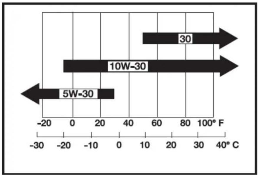
bar
| Temperature Range | Value | | :--- | :--- | | 5W-30 | -20 | | 10W-30 | -10 | | 30 | 80 |HYDRAULIC OIL RECOMMENDATIONS

IMPORTANT
Before delivery, the hydraulic oil used was an ISO 32 viscosity grade.
The recommended hydraulic oil type:
- 10W AW32
ASLE H-150 - ISO 32
GREASE RECOMMENDATIONS
| Application | Shell | Mobil | Exxon |
| Grease | Shell Alvania EP2 | Mobilux EP2 | BEACON Q2 |
3.23. Main dimensions
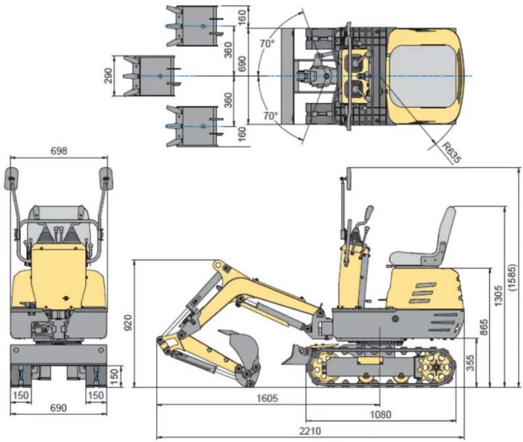
text_image
698 150 690 150 290 360 690 160 70° 360 160 R635 920 1605 1305 (1585) 865 355 1080 2210
text_image
1125* 2100 1350 740 490 150 130 1200 900 23301125*: 945 with boom swing
3.24. Lifting capacity
- The lifting capacities are based on ISO 10567 and do not exceed 75% of the static tilt load of the machine or 87% of the hydraulic lifting capacity of the machine.
- The strokes are as follows.
• The load point corresponds to the front bolt part of the arm.
• The machine positions are (i) over-front (Blade up), (ii) over-front (Blade down), and (iii) overside.
• The operating cylinder is the boom cylinder.
- The bucket of the machine, the hook, the sling and other lifting accessories are taken into consideration for the loads.
Machine conditions:
No bucket, all others are according to standard regulations.

WARNING!
- It is forbidden to lift loads greater than those values mentioned in the lifting capacity tables.
- The values mentioned in the table are valid only on even, hard ground. When lifting on soft ground, the machine 'can tilt over since the load is concentrated only on one side of the machine.
- The table values are calculated at the end of the arm without the bucket. To find the allowable loads for machines with bucket, the bucket weight must be subtracted from the values in the table.
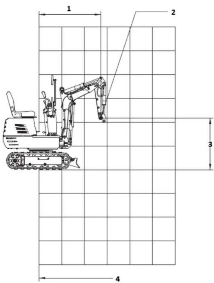
text_image
1 2 3 41- Lift point radius
2- Lift point
3- Lift point height
4- Axis of rotation
Lifting capacity
(i) OVER FRONT (BLADE UP)
Unit: kN (kg)
| HEIGHT(mm) | LOAD RADIUS (mm) | ||||||
| 0 | 380 | 760 | 1140 | 1520 | 1900 | 2280 | |
| 2400 | |||||||
| 2000 | |||||||
| 1600 | 1.1 (110) | ||||||
| 1200 | 1.1 (110) | ||||||
| 800 | 1.7 (170) | 1.1 (110) 0.8 (80) | |||||
| 400 | 1.7 (170) | 1.1 (110) 0.8 (80) | |||||
| 0 | 1.7 (170) | 1.1 (110) | |||||
| 400 | 3.2 (320) | 1.7 (170) | 1.1 (110) | ||||
| 800 | 1.3 (130) | ||||||
| 1200 | |||||||
(ii) OVER FRONT (BLADE DOWN)
Unit: kN (kg)
| HEIGHT(mm) | LOAD RADIUS (mm) | ||||||
| 0 | 380 | 760 | 1140 | 1520 | 1900 | 2280 | |
| 2400 | |||||||
| 2000 | |||||||
| 1600 | 1.4 (140) | ||||||
| 1200 | 1.4 (140) | ||||||
| 800 | 2.2 (220) | 1.6 (160) | 1.4 (140) | ||||
| 400 | 3.0 (300) | 1.9 (190) | 1.5 (150) | ||||
| 0 | 3.1 (310) 2.0 (200) | ||||||
| 400 | 3.2 (320) | 2.7 (270) | 1.7 (170) | ||||
| 800 | 1.3 (130) | ||||||
| 1200 | |||||||
3.25. Wiring diagram
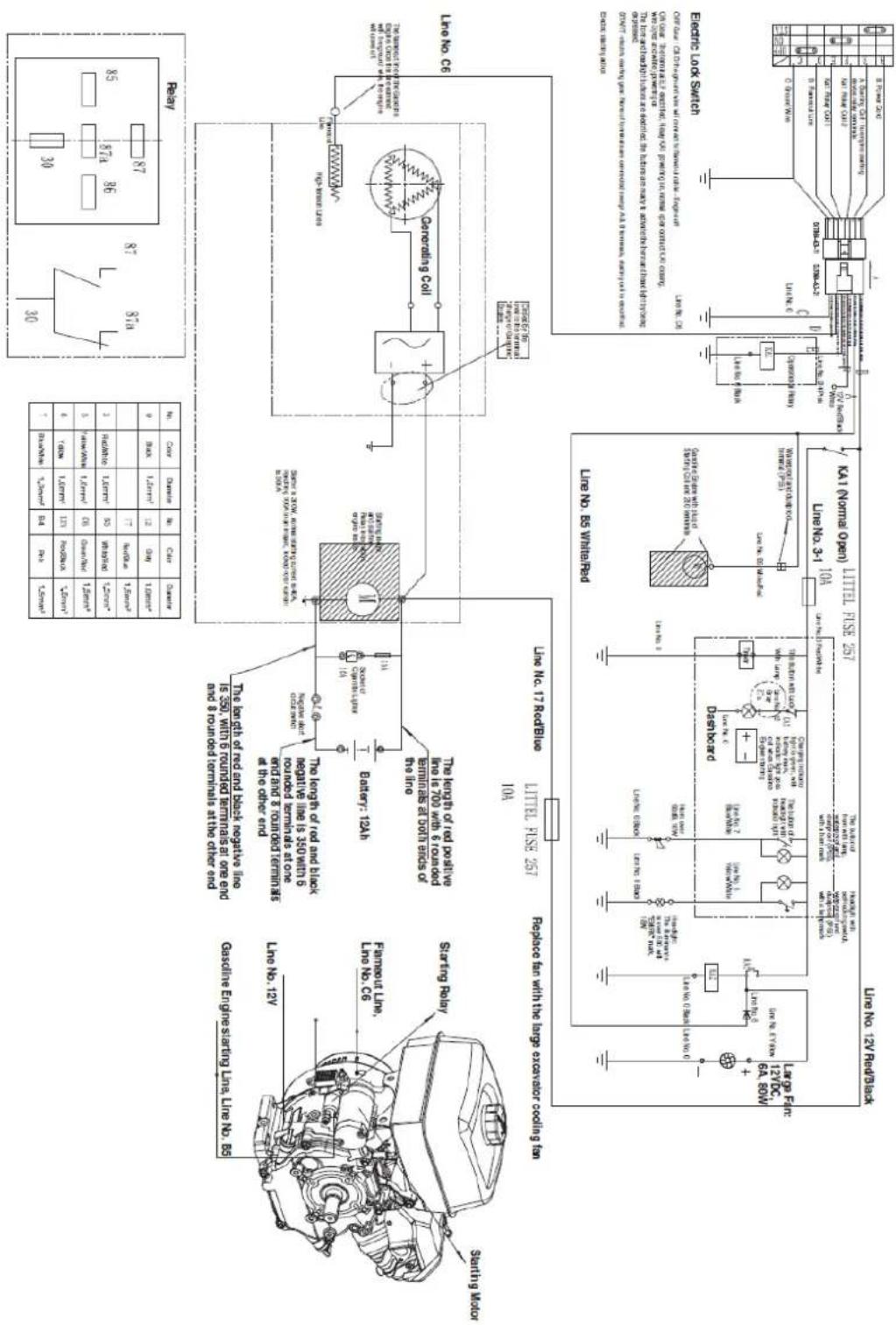
text_image
Line No 12V Rated/Black Starting Motor Fermostat Line. Line No. 12y Line No. 12y Sterling Relay Gasoline Engine Starting Line, Line No. 65 Line No. 12y Line No. 17 Redblide Line No. 17 Redblide Replace ran with the large exchanger cooling fan Line No. 3-1 Line No. 3-1 Line No. 3-1 Line No. 3-1 Line No. 3-1 Line No. 3-1 Line No. 3-1 Line No. 3-1 Line No. 3-1 Line No. 3-1 Line No. 3-1 Line No. 3-1 Line No. 3-1 Line No 3-1 Line No. 3-1 Line No. 3-1 Line No. 3-1 Line No. 3-1 Line No. 3-1 Line No. 3-1 Line No. 3-1 Line No. 3-1 Line No. 3-1 Line No. 3-1 Line No. 3-1 Line No. 3-2 Line No. 3-2 Line No. 3-2 Line No. 3-2 Line No. 3-2 Line No. 3-2 Line No. 3-2 Line No. 3-2 Line No. 3-2 Line No. 3-2 Line No. 3-2 Line No. 3-2 Line No. 3-2 Line No 3-2 Line No. 3-2 Line No. 3-2 Line No. 3-2 Line No. 3-2 Line No. 3-2 Line No. 3-2 Line No. 3-2 Line No. 3-2 Line No. 3-2 Line No. 3-2 Line No. 3-2 Line No. 3-1 Line No. 3-1 Line No. 3-1 Line No. 3-1 Line No. 3-1 Line No. 3-1 Line No. 3-1 Line No. 3-1 Line No. 3-1 Line No. 3-1 Line No. 3-1 Line No. 3-1 Line No. Line No. Line No. Line No. Line No. Line No. Line No. Line No. Line No. Line No. Line No. Line No. Line No. Line No. Line No. Line No. Line No. Line No. Line No. Line No. Line No. Line No. Line No. Line No. Line No. Line No. Line No. Line No. Line No. Line No. Line No. Line No. Line No. Line No. Side Power Source: Control unit (0 to -0) and power output (in Vdc) Power Source: Control unit (0 to -0) and power output (in Vdc) Power Source: Control unit (0 to -0) and power output (in Vdc) Power Source: Control unit (0 to -0) and power output (in Vdc) Power Source: Control unit (0 to -0) and power output (in Vdc) Power Source: Control unit (0 to -0) and power output (in Vdc) Power Source: Control unit(0 to -0) and power output(0 to -0) and power output(0 to -0) Power Source: Control unit(0 to -0) and power output(0 to -0) and power output(0 to -0) Power Source: Control unit(0 to -0) and power output(0 to -0) and power output(0 to -0) Power Source: Control unit(0 to -0) and power output(0 to -0) and power output(0 to -0) Power Source: Control unit(0 to -0)and power output(0 to -0) and power output(0 to -0) Power Source: Control unit(0 to -0) and power output(0 to -0) and power output(0 to -0) Power Source: Control unit(0 to -0) and power output(0 to -0) and power output(0 to -0) Power Source: Control unit(0 to -0) and power output(0 to -0) and power output(| No. | Color | Diameter | No. | Color | Diameter |
| 0 | Black | 1.5mm^2 | 1217 | GrayRed/Blue | 1.0mm^2 1.5mm^2 |
| 3 | Red/White | 1.0mm^2 | B5 | White/Red | 1.5mm^2 |
| 5 | Yellow/White | 1.0mm^2 | C6 | Green/Red | 1.5mm^2 |
| 6 | Yellow | 1.0mm^2 | 12V | Red/Black | 1.5mm^2 |
| 7 | Blue/White | 1.0mm^2 | B4 | Pink | 1.5mm^2 |
3.26. Hydraulic system diagram
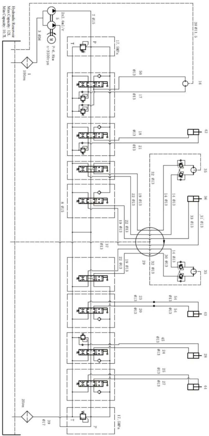
flowchart
graph TD
    A["17.5MPa"] --> B["8 015"]
    B --> C["37 013"]
    C --> D["22 013"]
    D --> E["19 013"]
    E --> F["22 013"]
    F --> G["19 013"]
    G --> H["22 013"]
    H --> I["19 013"]
    I --> J["22 013"]
    J --> K["19 013"]
    K --> L["22 013"]
    L --> M["19 013"]
    M --> N["22 013"]
    N --> O["19 013"]
    O --> P["22 013"]
    P --> Q["19 013"]
    Q --> R["22 013"]
    R --> S["19 013"]
    S --> T["22 013"]
    T --> U["19 013"]
    U --> V["22 013"]
    V --> W["19 013"]
    W --> X["22 013"]
    X --> Y["19 013"]
    Y --> Z["22 013"]
    Z --> AA["19 013"]
    AA --> AB["22 013"]
    AB --> AC["19 013"]
    AC --> AD["22 013"]
    AD --> AE["19 013"]
    AE --> AF["22 013"]
    AF --> AG["19 013"]
    AG --> AH["22 013"]
    AH --> AI["19 013"]
    AI --> AJ["22 013"]
    AJ --> AK["19 013"]
    AK --> AL["22 013"]
    AL --> AM["19 013"]
    AM --> AN["22 013"]
    AN --> AO["19 013"]
    AO --> AP["22 013"]
    AP --> AQ["19 013"]
    AQ --> AR["22 013"]
    AR --> AS["19 013"]
    AS --> AT["22 013"]
    AT --> AU["19 013"]
    AU --> AV["22 013"]
    AV --> AW["19 013"]
    AW --> AX["22 013"]
    AX --> AY["19 013"]
    AY --> AZ["22 013"]
    AZ --> BA["19 013"]
    BA --> BB["22 013"]
    BB --> BC["19 013"]
    BC --> BD["22 013"]
    BD --> BE["19 013"]
    BE --> BF["22 013"]
    BF --> BG["19 013"]
    BG --> BH["22 013"]
    BH --> BI["19 013"]
    BI --> BJ["22 013"]
    BJ --> BK["19 013"]
    BK --> BL["22 013"]
    BL --> BM["19 013"]
    BM --> BN["22 013"]
    BN --> BO["19 013"]
    BO --> BP["22 013"]
    BP --> BQ["19 013"]
    BQ --> BR["22 013"]
    BR --> BS["19 013"]
    BS --> BT["22 013"]
    BT --> BU["19 013"]
    BU --> BV["22 013"]
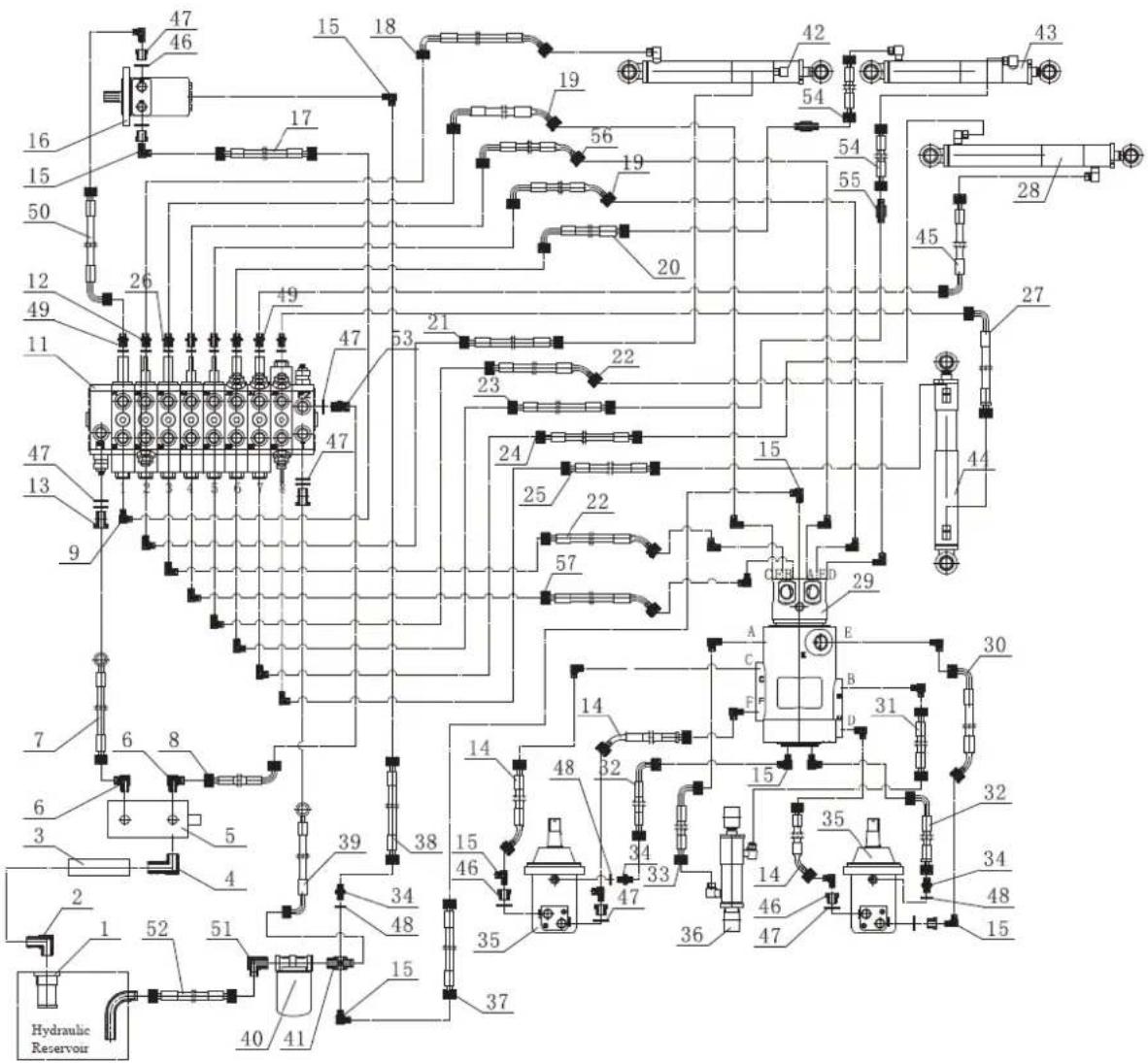
text_image
47 46 15 18 19 56 19 54 42 43 16 15 50 26 49 20 55 28 12 49 11 47 21 22 23 47 24 15 45 27 47 13 9 25 22 57 29 A E 30 6 8 39 38 14 48 32 15 35 32 6 3 5 4 15 46 34 33 14 46 47 47 36 35 34 48 15 2 1 52 51 Hydraulic Reservoir 40 41Parts list
| No. Description | Quantity | |
| 1 Oil Filter | 1 | |
| 2 | Oil Suction Angle Connector | 1 |
| 3 | Oil Suction Pipe | 1 |
| 4 | Pump Inlet Angle Connector | 1 |
| 5 | Double Gear Pump | 1 |
| 6 Angle Connector | 2 | |
| 7 | Pump Front Outlet Hose | 1 |
| 8 | Pump Rear Outlet Hose | 1 |
| 9 | Transition Joint G3/8-M14x1.5 | 8 |
| 10 | Angle Connector | 2 |
| 11 Multi-way Valve Assembly | 1 | |
| 12 | Straight Connector | 6 |
| 13 G1/2 Hollow Bolt | 2 | |
| 14 | Travel Motors Oil Hose | 3 |
| 15 | Angle Connector | 20 |
| 16 | Rotary Motor | 1 |
| 17 | Rotary Motor Oil Hose | 1 |
| 18 | Oil Hose 1 for Bucket Arm Cylinder | 1 |
| 19 | Valve-Swivel Joint Oil Hose (C, E) | 2 |
| 20 | Bucket Cylinder Oil Hose 1 | 1 |
| 21 | Oil Hose 2 for Bucket Arm Cylinder | 1 |
| 22 | Valve-Swivel Joint Oil Hose (D, F) | 2 |
| 23 Bucket Cylinder Oil Hose 2 | 1 | |
| 24 | Boom Cylinder Oil Hose 2 | 1 |
| 25 | Side Swing Cylinder Oil Hose 2 | 1 |
| 26 | Bonded Washer | 8 |
| 27 | Side Swing Cylinder Oil Hose 1 | 1 |
| 28 Boom Cylinder | 1 | |
| 29 | Centre Swivel Joint | 1 |
| 30 | Right Travel Motor Oil Hose | 1 |
| 31 | Dozer Cylinder Oil Hose 2 | 1 |
| 32 | Travel Motor Oil Drain Hose | 2 |
| 33 | Dozer Cylinder Oil Hose 1 | 1 |
| 34 | Straight Connector | 3 |
| 35 | Hydraulic Motor | 2 |
| 36 | Dozer Cylinder | 1 |
| 37 | Swivel Joint Oil Drain Hose | 1 |
| 38 | Rotary Motor Oil Drain Hose | 1 |
| 39 | Oil Return Hose | 1 |
| 40 | Oil Return Filter | 1 |
| 41 | Four-way Joint | 1 |
| 42 | Bucket Arm Cylinder | 1 |
| 43 | Bucket Cylinder | 1 |
| 44 | Side Swing Cylinder | 1 |
| 45 | Boom Cylinder Oil Hose 1 | 1 |
| 46 | G1/2-G1/4 Through-core connector | 6 |
| 47 | Bonded Washer | 11 |
| 48 | Bonded Washer | 3 |
| 49 | Straight Connector (with shutoff) | 2 |
| 50 | Rotary Motor Oil Hose | 1 |
| 51 | Angle Connector | 1 |
| 52 | Oil Return Hose | 1 |
| 53 | Straight Connector | 1 |
| 54 | Bucket Cylinder Oil Hose | 2 |
| 55 | Extended Nipple | 2 |
| 56 | Valve-Swivel Joint Oil Hose (A) | 1 |
| 57 | Valve-Swivel Joint Oil Hose (B) | 1 |
3.27. Parts diagram
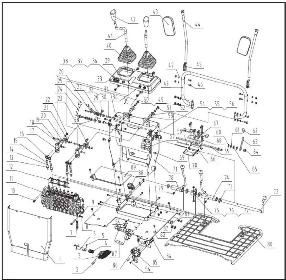
text_image
Exploded view diagram of a mechanical assembly with numbered components for identification3.28. Parts list
| No. Description | Quantity | |
| 1 Control Cabinet- Rear Plate | 1 | |
| 2 Pedal Pin Shaft D10x55 | 1 | |
| 3 Boom Swing Pedal | 1 | |
| 4 Pedal Shaft Spring | 1 | |
| 5 Pedal Pin Shaft - Cotter Pin D2x16 | 1 | |
| 6 | Boom Swing Pedal-Shaft Weldment | 1 |
| 7 Valve Bottom Connecting Rod | 1 | |
| 8 Connecting Rod- Shaft Pin D5x18 | 7 | |
| 9 Connecting Rod- Cotter Pin D1.5x16 | 11 | |
| 10 Screw M10x60 | 2 | |
| 11 | Multi-Way Valve Assembly | 1 |
| 12 Connecting Rod | 3 | |
| 13 Straight Joint Bearing M8 | 2 | |
| 14 Nut M8 | 4 | |
| 15 Connecting Rod M8x80 | 4 | |
| 16 | Elbow Lever Knob Joint Bearing SQ8-RS JB/T5306 | 2 |
| 17 | Operating Control Lever- Direction Block | 2 |
| 18 Screw M8x25 | 4 | |
| 19 Universal Support Pin Shaft 10x45 | 2 | |
| 20 | Operating Control Lever- Universal Joint Weldment | 2 |
| 21 Spring Washer D8 | 12 | |
| 22 Nut M8 | 8 | |
| 23 Flat Washer D10 | 6 | |
| 24 Cable Lever Weldment | 1 | |
| 25 Dozer Ball Knob | 4 | |
| 26 Big Washer D6 | 1 | |
| 27 Choke Torsion Spring | 1 | |
| 28 Throttle Cable Plate Weldment | 1 | |
| 29 Choke Cable Plate Weldment | 1 | |
| 30 Choke Lever Shaft | 1 | |
| 31 Lock Nut M5 | 1 | |
| 32 Bolt M5x10 | 1 | |
| 33 | Control Cabinet-Top Plate Weldment | 1 |
| 34 Horn Button | 1 | |
| 35 Headlamp Button | 1 | |
| 36 Timer | 1 | |
| 37 Screw M4x14 | 2 | |
| 38 Lock Nut M4 | 2 | |
| 39 Power Indicator Light | 1 | |
| 40 Drive Lever Sleeve | 2 | |
| 41 Left/Right Drive Lever | 2 | |
| 42 Operating Ball Knob | 2 | |
| 43 Rearview Mirror | 2 | |
| 44 | Rearview Mirror- Supporting Tube | 2 |
| 45 Rearview Mirror- Frame | 2 | |
| 46 Bolt M8x25 | 6 | |
| 47 Flat Washer D8 | 4 | |
| 48 Handle Weldment | 1 | |
| 49 Flat Washer D10 | 4 | |
| 50 Spring Washer D10 | 6 | |
| 51 Bolt M10-20 | 6 | |
| 52 Large Washer A4 | 2 | |
| 53 Copper Sleeve | 2 | |
| 54 Bolt M6x16 | 9 | |
| 55 Spring Washer D6 | 9 | |
| 56 Flat Washer D6 | 9 | |
| 57 Electric Relay | 2 | |
| 58 Pin D5x100 | 2 | |
| 59 | Lever Lock Rotating Shaft Weldment | 1 |
| 60 | Anti-Slip Wear Washer | 4 |
| 61 Washer D12 | 4 | |
| 62 Locking Handle | 2 | |
| 63 Locking Lever | 2 | |
| 64 Lock Nut M12 | 3 | |
| 65 Wave Spring Washer D12 | 2 | |
| 66 | Lock Plugboard- Middle Connecting Plate | 1 |
| 67 Left/Right Lock Plugboard | 2 | |
| 68 Locking Plate for Operating Lever | 1 | |
| 69 Flange Bolt M8x16 | 37 | |
| 70 Lock Plugboard Weldment | 1 | |
| 71 | Operation Dashboard- Front Guard Plate | 1 |
| 72 Rotating Shaft Weldment | 1 | |
| 73 O-Ring 34x4 | 4 | |
| 74 Right Handle Weldment | 1 | |
| 75 Dozer Shaft Sleeve Weldment | 1 | |
| 76 Bolt M8x45 | 1 | |
| 77 Lock Nut M8 | 1 | |
| 78 Left Handle Weldment | 1 | |
| 79 Grease Cup M6X1 | 2 | |
| 80 Rubber Pads | 1 | |
| 81 Grease Cup M10 | 2 | |
| 82 PD610 Straight Fitting | 2 | |
| 83 | Control Cabinet- End Plate Weldment | 1 |
| 84 Nut M6 | 2 | |
| 85 Battery Negative Switch | 1 | |
| 86 Cigarette Lighter Socket | 1 | |
| 87 Oil Filter | 1 | |
| 88 Horn (DC12V 105dB high) | 1 | |
| 89 Engine Cover Plate Weldment | 1 | |
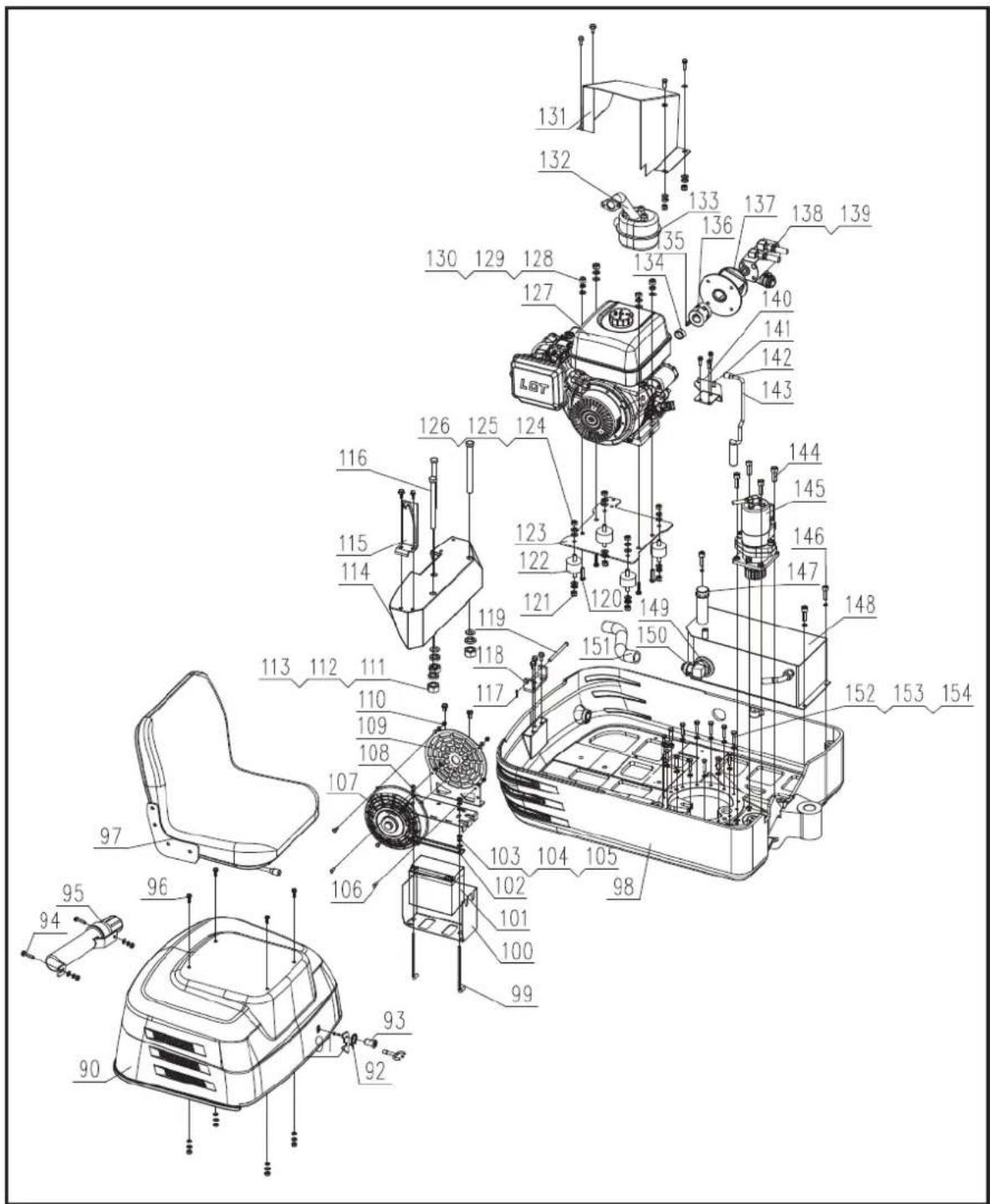
text_image
Exploded view diagram of a mechanical assembly with numbered components and labeled parts| No. Description | Quantity | |
| 90 | Engine Cover Weldment | 1 |
| 91 Lock Hook | 1 | |
| 92 Torsion | Spring | 1 |
| 93 | 40mm Triangle-Lock Core with Key | 1 |
| 94 Bolt M8x25 | 2 | |
| 95 Manua | Storage Cylinder | 1 |
| 96 Bolt M8x16 | 16 | |
| 97 | Excavator integrated seat (with slide) | 1 |
| 98 Swing Unit Platform | 1 | |
| 99 Battery Lock Hook | 2 | |
| 100 Battery Mounting plate | 1 | |
| 101 Battery | 1 | |
| 102 Battery Fixing Plate | 1 | |
| 103 Spring Washer 8 | 31 | |
| 104 Flat Washer 8 | 33 | |
| 105 Nut M8 | 15 | |
| 106 Screw M6x14 | 4 | |
| 107 Fan | 1 | |
| 108 Battery Cover Weldment | 1 | |
| 109 Cooling Fan Mounting Frame | 1 | |
| 110 Lock Nut M6 | 4 | |
| 111 Nut M14 | 3 | |
| 112 Flat Washer 14 | 3 | |
| 113 | Spring Washer 14 | 3 |
| 114 Counter Weight | 1 | |
| 115 Motor Cover Turnover Support | 1 | |
| 116 Bolt M14x170 | 3 | |
| 117 Cotter Pin 2x16 | 1 | |
| 118 Motor Cover Mounting Base | 1 | |
| 119 Pin 8x110 | 1 | |
| 120 Bolt M12x35 | 4 | |
| 121 All Metal Lock Nut M10 | 4 | |
| 122 Shock Absorber | 4 | |
| 123 | Engine Mounting Plate Weldment | 1 |
| 124 Nut M10 | 4 | |
| 125 Flat Washer 10 | 8 | |
| 126 Spring Washer 10 | 12 | |
| 127 Engine | 1 | |
| 128 Nut M12 | 4 | |
| 129 Spring Washer 12 | 4 | |
| 130 Spring Washer 12 | 4 | |
| 131 Engine Guard Plate | 1 | |
| 132 | Connecting Hose Weldment for Muffler | 1 |
| 133 | Muffler - Inside Tank | 1 |
| 134 Coupler Sleeve | 1 |
| 135 Key 7x7x23 | 1 |
| 136 Coupler KSP24 | 1 |
| 137 Gear Pump Frame | 1 |
| 138 Gear Pump | 1 |
| 139 Bolt M8x150 | 2 |
| 140 Muffler Frame | 1 |
| 141 Bolt M6x16 | 2 |
| 142 Locking Pin Handlebar sleeve | 1 |
| 143 Locking Pin Weldment | 1 |
| 144 Screw M10x35 | 4 |
| 145 Rotary Motor Assy | 1 |
| 146 Screw M8x25 | 3 |
| 147 Hydraulic Oil Tank Cover | 3 |
| 148 Hydraulic Oil Tank Weldment | 1 |
| 149 Oil suction filter | 1 |
| 150 Hose Clamp | 2 |
| 151 Suction Hose | 1 |
| 152 Bolt M8x45 | 16 |
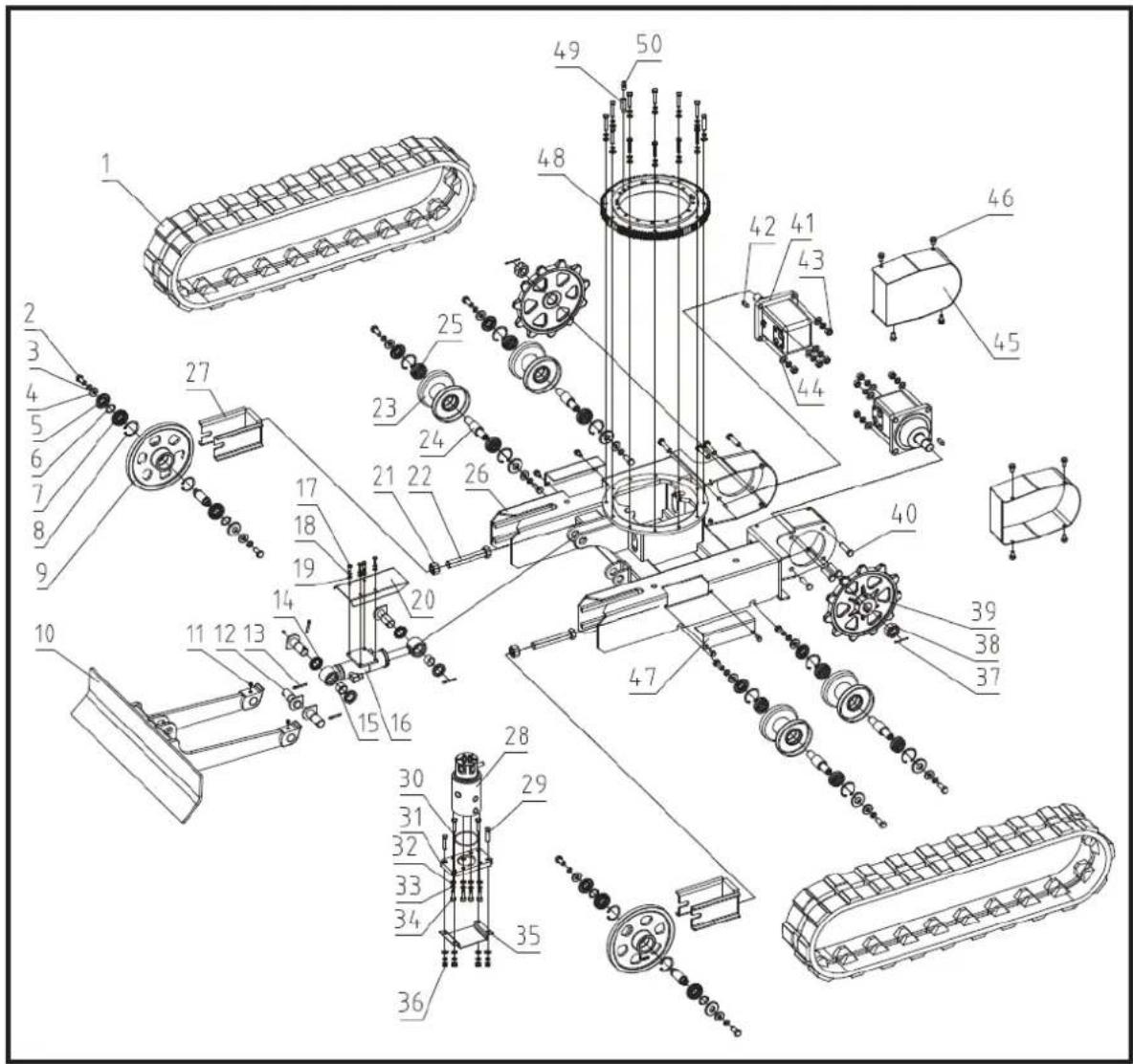
text_image
Technical diagram of a tracked vehicle with numbered components and exploded view, likely for assembly or maintenance purposes.| No. | Description | Quantity |
| 1 | Rubber Track 150x72x32 | 2 |
| 2 | Bolt M12x30 | 12 |
| 3 | Spring Washer 12 | 28 |
| 4 | Washer | 12 |
| 5 | Seal B20x47x7 | 12 |
| 6 | Circlip A25 | 4 |
| 7 | Bearing 6005-2Rs | 4 |
| 8 | Circlip A47 | 12 |
| 9 | Front Idler | 2 |
| 10 | Dozer | 1 |
| 11 | Oil Cup M6x1 | 2 |
| 12 | Dozer Pin Shaft Weldment | 4 |
| 13 | Cotter Pin 5x35 | 4 |
| 14 | Seal B25x40x7 | 4 |
| 15 | RCB-20 Boundary Lubricating Bearing | 2 |
| 16 | Dozer Cylinder | 1 |
| 17 | Bolt M6x16 | 17 |
| 18 | Spring Washer 6 | 26 |
| 19 | Flat Washer 6 | 20 |
| 20 | Dozer Cylinder Guard Plate | 1 |
| 21 | Nut M20 | 2 |
| 22 | Hex Bolt M20x130 | 2 |
| 23 | Supporting Roller | 4 |
| 24 | Supporting Roller Axle | 4 |
| 25 | Bearing 6204-2Rs | 8 |
| 26 | Base Weldment | 1 |
| 27 | Front Idler Fixing Frame | 2 |
| 28 | Central Swivel | 1 |
| 29 | Bolt M8x45 | 32 |
| 30 | O-Ring D72x3.1 | 1 |
| 31 | Central Swivel Mounting Plate | 1 |
| 32 | Flat Washer 8 | 58 |
| 33 | Spring Washer 8 | 58 |
| 34 | Screw M8x25 | 11 |
| 35 | Central Swivel Guard Plate | 1 |
| 36 | Nut M8 | 28 |
| 37 | Cotter Pin 4x45 | 2 |
| 38 | Axle Nut 1-20UNEF | 2 |
| 39 | Drive Sprocket | 2 |
| 40 | Bolt M12x45 | 8 |
| 41 | Hydraulic Motor | 2 |
| 42 | Arch Key φ25.4x7 | 2 |
| 43 | Hexagon Lock Nut M12 | 8 |
| 44 | Flat Washer 12 | 23 |
| 45 | Motor Cover Weldment | 2 |
| 46 | Flange Bolt M8x16 | 69 |
| 47 | Track-tension Adjusting Hole Cover | 2 |
| 48 | Central Swing Circular Support | 1 |
| 49 | Central Swing Circular Support- Lubricating Joint | 1 |
| 50 | Straight Fitting PD610(With Neck Bush) | 4 |
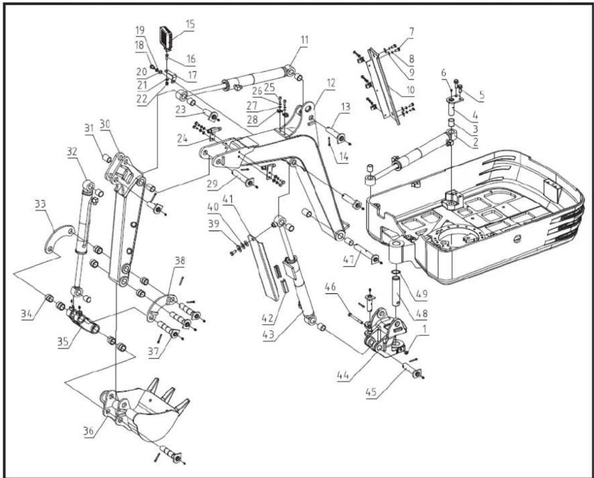
text_image
Technical diagram of a mechanical assembly with numbered components for identification| No. | Description | Quantity |
| 1 | Lock Nut M10 | 1 |
| 2 | Boom Swing Cylinder | 1 |
| 3 | RCB-20 Boundary Lubricating Bearing 28x25x35 | 8 |
| 4 | Boom Swing Cylinder-Rear Pin Weldment | 1 |
| 5 | Flange Bolt M8x16 | 2 |
| 6 | Oil Cup M6 | 16 |
| 7 | Blot 8x16 | 4 |
| 8 | Spring Washer 8 | 8 |
| 9 | Flat Washer 8 | 4 |
| 10 | Boom Upper-hose Cover-Plate Weldment | 1 |
| 11 | Arm Cylinder | 1 |
| 12 | Boom Weldment | 1 |
| 13 | Boom Pin Shaft Weldment | 2 |
| 14 | Cotter Pin 5x35 | 12 |
| 15 | Work Light | 1 |
| 16 | Bolt M8x20 | 7 |
| 17 | Light Mounting Plate | 1 |
| 18 Bolt M10x20 | 2 | |
| 19 Spring Washer 10 | 1 | |
| 20 Flat Washer 10 | 1 | |
| 21 Flat Washer 8 | 5 | |
| 22 Lock Nut M8 | 1 | |
| 23 Arm Cylinder Pin Shaft Weldment | 3 | |
| 24 Transition Fitting | 2 | |
| 25 Bolt M6x20 | 5 | |
| 26 Spring Washer 6 | 5 | |
| 27 Flat Washer 6 | 5 | |
| 28 Connecting Pipe Clamp R-type | 5 | |
| 29 Arm Cylinder Pin Shaft Weldment | 1 | |
| 30 Arm Weldment | 1 | |
| 31 RCB-20 Boundary Lubricating Bearing 28x25x40 | 4 | |
| 32 Bucket Cylinder | 1 | |
| 33 | Arm Rocker-Right | 1 |
| 34 Bucket Shaft Sleeve | 8 | |
| 35 Connecting Rod | 1 | |
| 36 Shovel Weldment | 1 | |
| 37 Shovel Pin Weldment | 4 | |
| 38 | Arm Rocker-Left | 1 |
| 39 Flat Washer 10 | 1 | |
| 40 Wing Spring | 2 | |
| 41 Boom Cylinder-Guide Plate | 1 | |
| 42 Guide Plastic Block | 2 | |
| 43 | Boom Up & Down Cylinder | 1 |
| 44 Boom Swing Frame | 1 | |
| 45 | Boom Swing Frame- Pin Shaft Weldment II | 1 |
| 46 Bolt M10x100 | 1 | |
| 47 | Boom Swing Frame- Pin Shaft Weldment I | 1 |
| 48 | Boom Swing Frame Pin Shaft 35x155 | 1 |
| 49 Circlip A35 | 1 | |
3.29. Attachments (Sold separately)
The simple construction of these attachments allows one person to install them on machines for quick job changeovers.
With the help of attachments, your machine can become many additional tools for a wider variety of jobs, which makes the machine more efficient.
Pallet forks (Sold separately)
The pallet forks are connected to the dozer blade, which can transport, load and unload various materials with pallets.
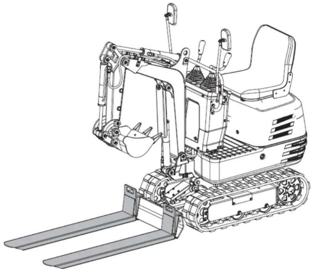
natural_image
Technical line drawing of a tracked excavator with levers and motors (no text or symbols)Pallet Forks Installation
Stop the machine and lower the bucket to the ground. Slightly loosen the bolts M10x40 and nuts attached to the pallet forks. Lift the dozer blade a little and hook the two pallet forks to it. Tighten the bolts to secure the connection.
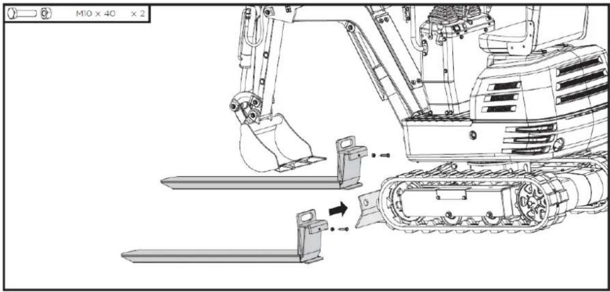
natural_image
Technical line drawing of a tracked excavator assembly with mounting bracket and guide rails (no text or symbols)Rake (Sold separately)
The rake is connected to the end of the bucket, which is ideal for collecting straw, screening debris or flattening the ground.
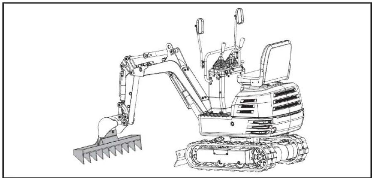
natural_image
Line drawing of an excavator with tracked blade and bucket (no text or symbols)Rake Installation
Stop the machine and lift the bucket off the ground to a certain height. Remove the bolts M12x40, washers and nuts preinstalled on the rake. Mount the rake to the bucket with these standard parts.

natural_image
Technical line drawing of an excavator and tracked vehicle (no text or symbols)Thumb (Sold separately)
The thumb can hold materials in place in the bucket. It can be used together with the bucket to grip regularly or irregularly shaped materials, such as rocks, timbers or demolition debris.
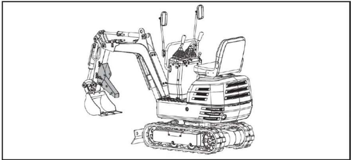
natural_image
Line drawing of an excavator with tracked base and mechanical components (no text or symbols)Thumb Installation
Demount the pin shafts 20x120, washers and R-pins from the thumb bracket.
Attach the bracket to the arm and align the holes. Pass two pin shafts through the holes, put on the washers and fix with R-pins.
Insert the bigger end of the thumb into the bracket, align the holes and fasten with the other two pin shafts, washers and R-pins.
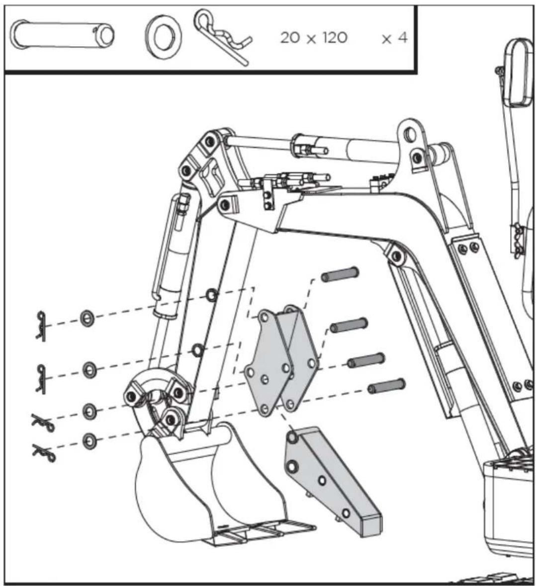
text_image
20 x 120 x 4When the thumb is not in use, pull out the lower R-pin and the pin shaft, fold up the thumb into the bracket and fix it in the upper position with the previously pulled out parts.
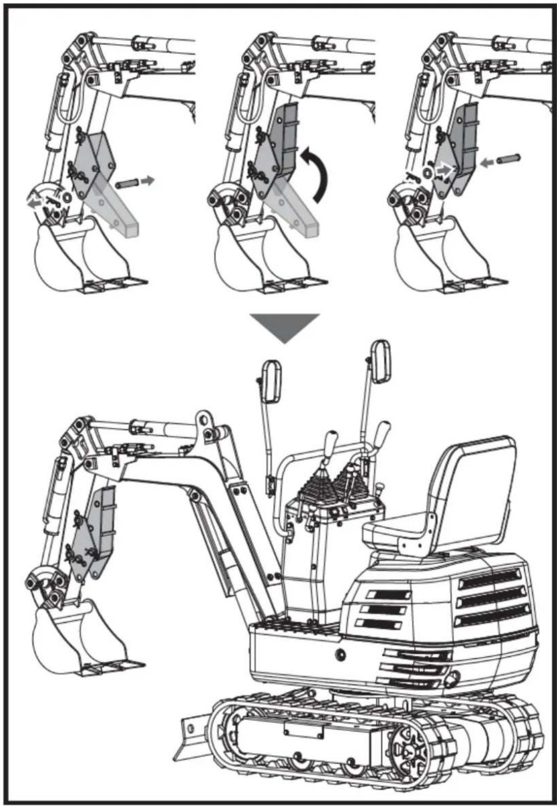
text_image
Technical diagram showing the assembly of an excavator with labeled components and motion arrows indicating changes.Claw (Sold separately)
The clamp without cover can be used to collect leaves, gravel and straw. The complete claw with cover is ideal for material of small particles like sand and soil.
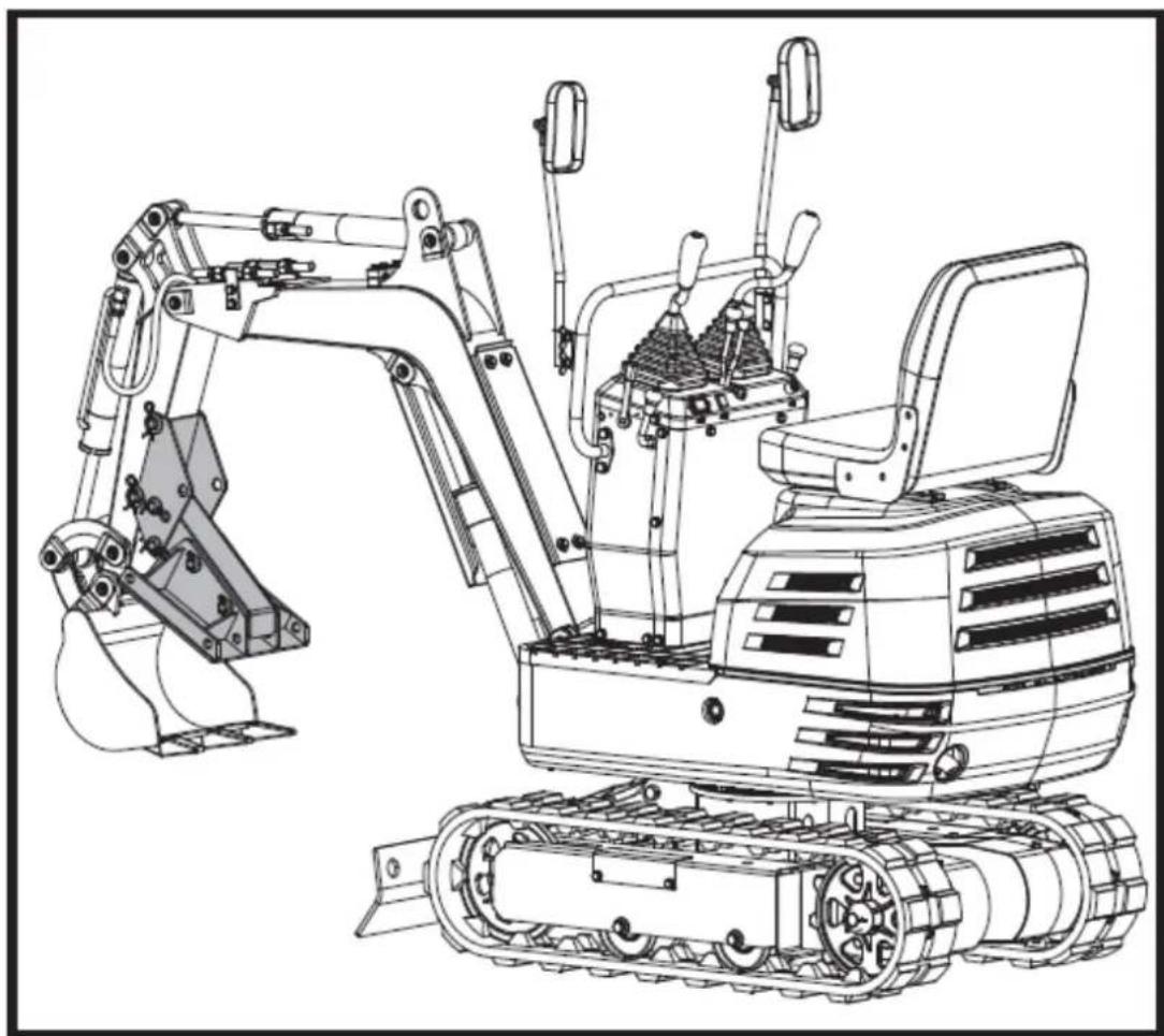
natural_image
Technical line drawing of an excavator with tracked components and control panel (no text or symbols)Claw Installation
- Demount the pin shafts 16x110, washers and R-pins from the clamp. Install the clamp to the thumb, align the holes and secure with the pin shafts, washers and R-pins.
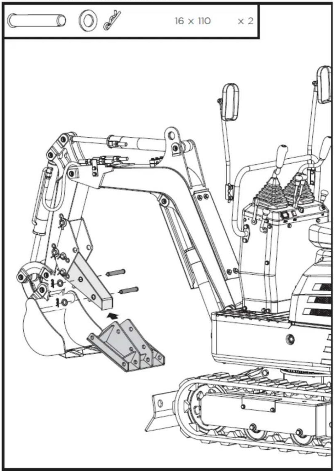
text_image
16 x 110 x 2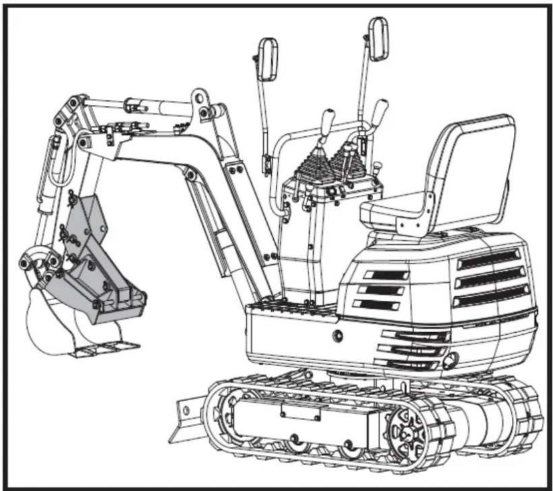
natural_image
Technical line drawing of a tracked excavator with attached mechanical components (no text or symbols)- Demount the pin shafts 16x300, washers and R-pins from the claw cover. Attach the cover to the clamp from outer side and align the holes. Pass the pin shafts 16x300 through the holes, put on the washers and fix with R-pins.
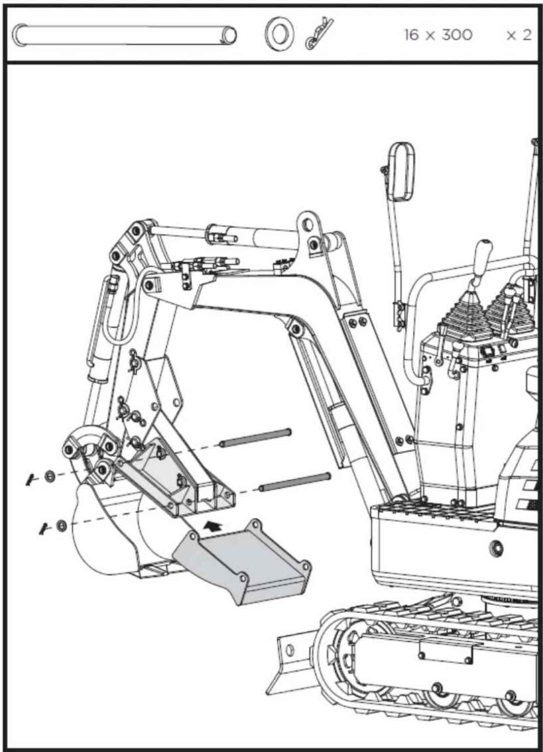
text_image
16 x 300 x 2Grading bucket (Sold separately)
The grading bucket is for replacing the standard bucket on the machine. With a bigger capacity, it can double the working efficiency when digging loose materials.
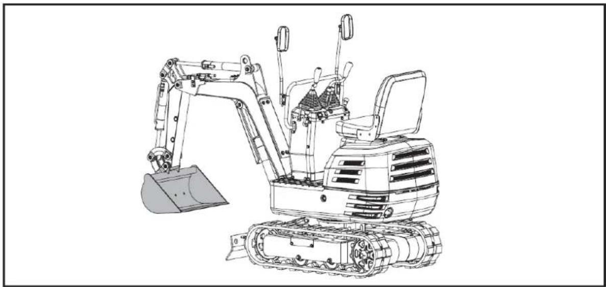
natural_image
Line drawing of an excavator with tracked base and blade assembly (no text or symbols)Grading Bucket Installation
Stop the machine and rest the bucket on the ground. Remove the shovel pin weldment, then remove the standard bucket off the machine. Mount the grading bucket onto the machine with the removed pins from the first step.
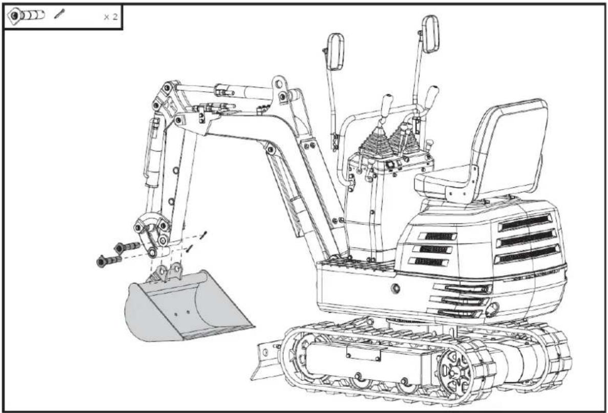
natural_image
Technical line drawing of an excavator with tracked base and bucket, no text or symbols presentCanopy (Sold separately)
The canopy is connected to the swing unit platform. It is ideal for offering protections from sunlight, rain and other precipitations. It is easy to be installed and disassembled.
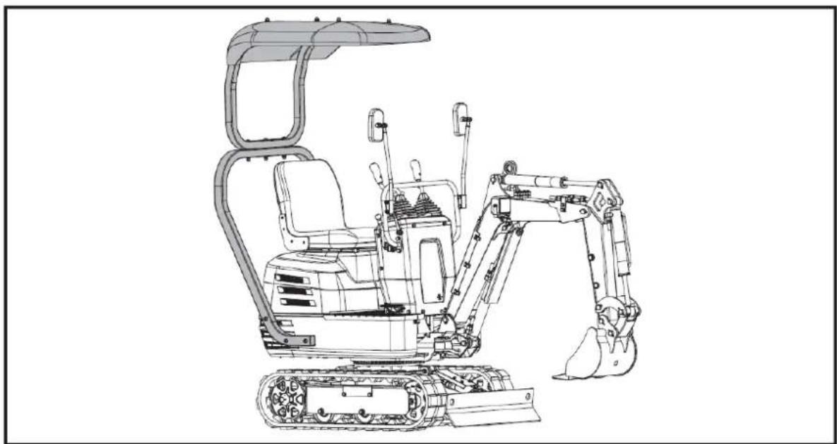
natural_image
Line drawing of an excavator with tracked base and attached bucket (no text or symbols)Canopy Installation
Align the holes in the lower frame of the canopy with the holes in the swing unit platform as shown. Fasten the lower frame in place with the provided M10x60 bolts and washers.
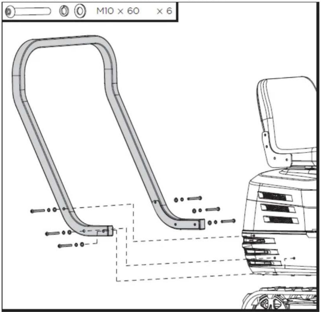
text_image
M10 x 60 x 6Align the holes in the upper frame with the holes in the lower frame of the canopy as shown. Secure the connection with the provided M10x95 bolts, washers and nuts.
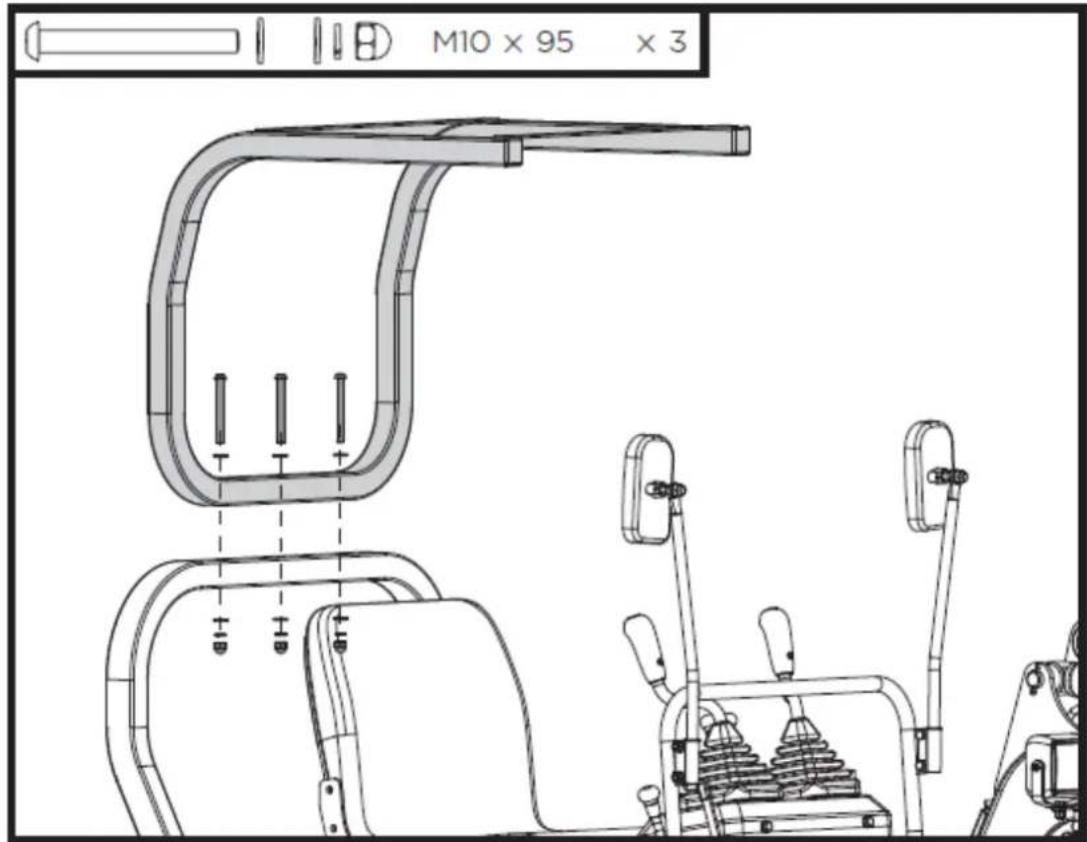
text_image
M10 x 95 x 3Align the holes in the canopy top with the holes in the upper frame of the canopy as shown. Fasten the canopy top in place with the provided M8x25 bolts, washers and nuts.
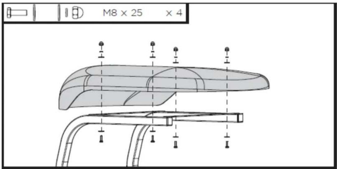
text_image
M8 x 25 x 44. Use guide to the engine

DANGER!
Using an engine indoors CAN KILL YOU IN MINUTES.
Engine exhaust contains carbon monoxide. This is a poison you cannot see or smell.
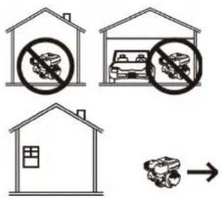
text_image
Diagram illustrating three types of transportation methods: no litter, car storage, and vehicle collision.NEVER use inside a home or garage, EVEN IF doors and windows are open.
Only use OUTSIDE and far away from windows, doors, and vents.

NOTICE!
Do not use E15 or E85 fuel in this product. It will damage the unit and void your warranty. Only use unleaded gasoline containing up to 10% ethanol.

text_image
ETHANOL E0 FREE E10 E15 E85ENGINE SAFETY
IMPORTANT SAFETY INFORMATION
Most accidents with engines can be prevented if you follow all instructions in this manual and on the engine. Some of the most common hazards are discussed below, along with the best way to protect yourself and others.
Owner Responsibilities
- The engines are designed to give safe and dependable service if operated according to instructions. Read and understand this owner's manual before operating the engine. Failure to do so could result in personal injury or equipment damage.
- Know how to stop the engine quickly, and understand the operation of all controls. Never permit anyone to operate the engine without proper instructions.
- Do not allow children to operate the engine. Keep children and pets away from the area of operation.
Refuel With Care
Gasoline is extremely flammable, and gasoline vapor can explode. Refuel outdoors, in a well-ventilated area, with the engine stopped. Never smoke near gasoline, and keep other flames and
sparks away. Always store gasoline in an approved container. If any fuel is spilled, make sure the area is dry before starting the engine.
Hot Exhaust
- The muffler becomes very hot during operation and remains hot for a while after stopping the engine. Be careful not to touch the muffler while it is hot. Let the engine cool before storing it indoors.
- To prevent fire hazards and to provide adequate ventilation for stationary equipment applications, keep the engine at least 3 feet (1 meter) away from building walls and other equipment during operation. Do not place flammable objects close to the engine.
Carbon Monoxide Hazard
Exhaust gas contains poisonous carbon monoxide. Avoid inhalation of exhaust gas. Never run the engine in a closed garage or confined area.
Other Equipment
Review the instructions provided with the equipment powered by this engine for any additional safety precautions that should be observed in conjunction with engine startup, shutdown, operation, or protective apparel that may be needed to operate the equipment.
SYMBOLS
 | Fire |  | Read Manual |  WARNINGWe do not approve or authorize the use of these engines on 3-wheel All-Terrain Vehicles (ATVs), motor bike s, fun/recreational go -karts, aircraft products or vehicles intended for use in competitive events. Use of these engines in such applications could result in property damage, serious injury (including paralysis), or even death. WARNINGWe do not approve or authorize the use of these engines on 3-wheel All-Terrain Vehicles (ATVs), motor bike s, fun/recreational go -karts, aircraft products or vehicles intended for use in competitive events. Use of these engines in such applications could result in property damage, serious injury (including paralysis), or even death. |
 | Explosion |  | Oil | |
 | Kickback |  | Fuel | |
 | Hot Surface |  | Fuel Shutoff | |
 | Toxic Fumes |  | Hazardous Chemical | CAUTIONThis engine is shipped from us without oil. If you start the engine without oil, the engine will be damaged beyond repair and will not be covered under warranty. |
 | Moving parts |  | Choke | |
 | Shock |  | Stop | |
 | Slow |  | Fast |

WARNING! Read all instructions.
Failure to follow all instructions listed below may result in fire, serious injury and/or DEATH.
The warnings and precautions discussed in this manual cannot cover all possible conditions and situations that may occur. It must be understood by the operator that common sense and caution are factors which cannot be built into this product but must be supplied by the operator.
4.1. Components & control locations
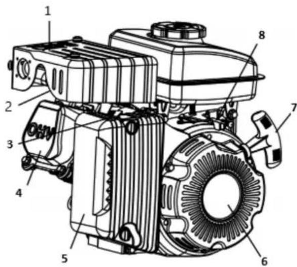
text_image
Technical diagram of an electric motor with numbered components for identification1- Muffler
2- Spark plug
3- Choke
4- Cylinder head cover
5- Air filter
6- Recoil starter
7- Starter handle
8- Throttle control assy
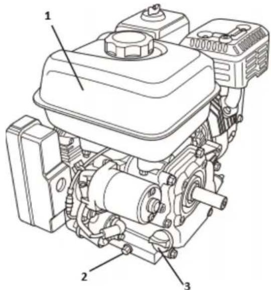
text_image
Technical diagram of a mechanical engine with numbered components labeled 1, 2, and 31- Fuel tank
2- Oil drain plug
3- Filler cap/dipstick
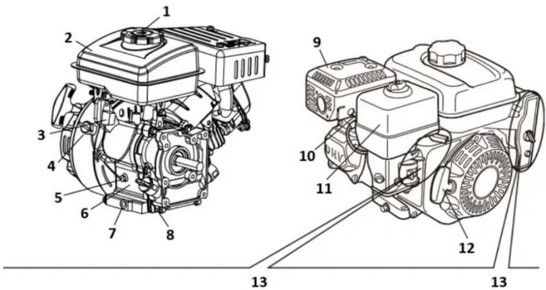
text_image
Technical diagram of a mechanical engine assembly with numbered components for identification.1- Fuel tank cap
2- Fuel tank
3- Oil alert
4- Engine switch
5- Oil sensor
6- Serial number location
7- Oil drain plug
8- Oil dipstick
9- Muffle
10- Spark plug
11- Air cleaner
12- Starter grip
13- Engine control types
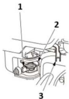
text_image
Technical diagram of a mechanical device with numbered parts labeled 1, 2, and 3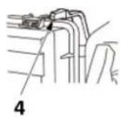
A
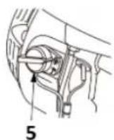
B
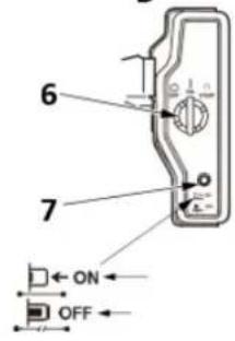
text_image
6 7 ON OFF1- Fuel valve lever
2- Choke lever
3- Throttle lever
4- Choke lever (air cleaner low-profile type)
5- Engine switch
6- Engine switch
7- Circuit protector
A- Except electric starter types
B- Electric starter types
4.2. Controls
Fuel valve lever
The fuel valve opens and closes the passage between the fuel tank and the carburettor. The fuel valve lever must be in the ON position for the engine to run.
When the engine is not in use, leave the fuel valve lever in the OFF position to prevent carburettor flooding and to reduce the possibility of fuel leakage.
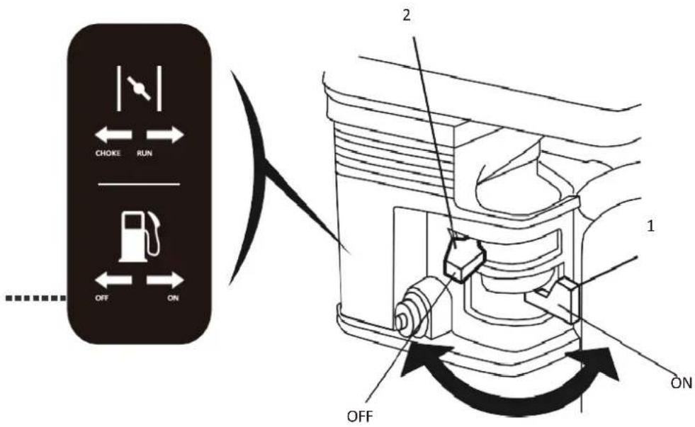
text_image
CHOKE RUN OFF ON 2 1 ON OFF1- Fuel valve lever
2- Choke lever
Throttle Lever
The throttle lever controls engine THROTTLE LEVER speed.
Moving the throttle lever in the directions shown makes the engine run faster or slower.
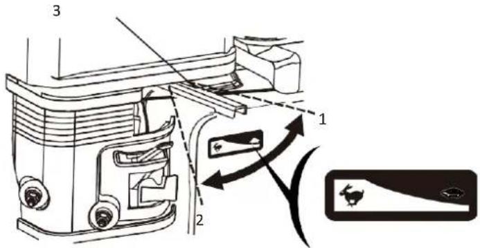
text_image
Technical diagram of a mechanical device with labeled components and directional arrows indicating motion or assembly.1- Slow
2- Fast
3- Throttle lever
Engine Switch
The engine switch enables and disables the ignition system.
The engine switch must be in the ON position for the engine to run. Turning the engine switch to the OFF position stops the engine.
ALL ENGINE EXCEPT E TYPE
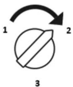
text_image
1 2 31- OFF
2- ON
3- Engine switch
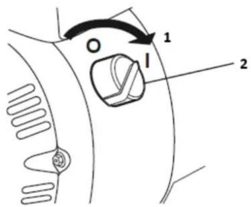
text_image
O 1 I 21- ON
2- Engine switch
Choke Lever
The choke lever opens and closes the choke valve in the carburettor. The CLOSE position enriches the fuel mixture for starting a cold engine.
The OPEN position provides the correct fuel mixture for operation after starting, and for restarting a warm engine.
Some engine applications use a remotely-mounted choke control rather than the engine-mounted choke lever shown here.
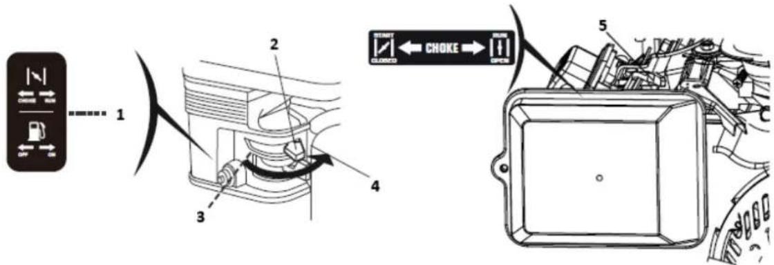
text_image
1 2 3 4 5 START CLOSED CHoke OPEN1- Open
2- Choke lever
3- Close
4- Open
5- Choke lever
Recoil Starter Grip
Pulling the starter grip operates the recoil starter to crank the engine.
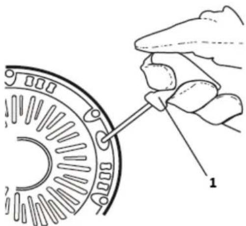
natural_image
Illustration of a hand turning a mechanical component with a tool (no text or symbols)1- Starter grip
For your safety, and to maximize the service life of your equipment, it is very important to take a few moments before you operate the engine to check its condition. Be sure to take care of any problem you find, or have your servicing dealer correct it, before you operate the engine.
Always perform a pre-inspection before each operation and correct any problem.
Before beginning your pre-inspection checks, be sure the engine is level, and the engine switch is in the OFF position.
Check the General Condition of the Engine
- Look around and underneath the engine for signs of oil or gasoline leaks.
- Remove any excessive dirt or debris, especially around the muffler and recoil starter.
- Look for signs of damage.
- Check that all shields and covers are in place, and all nuts, bolts, and screws are tightened.
Check the Engine
Check the engine oil level. Running the engine with a low oil level can cause engine damage.
The Oil Alert system (applicable engine types:TR79/TR196/TR389) will automatically stop the engine before the oil level falls below safe limits. However, to avoid the inconvenience of an unexpected shutdown, always check the engine oil level before startup.
Check the air filter. A dirty air filter will restrict air flow to the carburettor, reducing engine performance.
Check the fuel level. Starting with a full tank will help to eliminate or reduce operating interruptions for refuelling.
Check the Equipment Powered by This Engine
Review the instructions provided with the equipment powered by this engine for any precautions and procedures that should be followed before engine startup.
4.4. Operation
SAFE OPERATING PRECAUTIONS
Before operating the engine for the first time, please review the IMPORTANT SAFETY INFORMATION and the chapter titled BEFORE OPERATION.

Carbon monoxide gas is toxic. Breathing it can cause unconsciousness and even kill you. Avoid any areas or actions that expose you to carbon monoxide.
Review the instructions provided with the equipment powered by this engine for any safety precautions that should be observed in conjunction with engine startup, shutdown, or operation.
Starting the engine
- Move the fuel valve lever to the ON position.
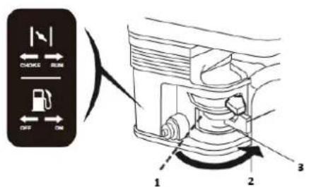
text_image
CHECK RUN OFF ON 1 2 31-OFF
2- ON
3- Fuel valve lever
- To start a cold engine, move the choke lever to the CLOSE position.
To restart a warm engine, leave the choke lever in the OPEN position.
Some engine applications use a remotely-mounted choke control rather than the engine-mounted choke lever shown here.
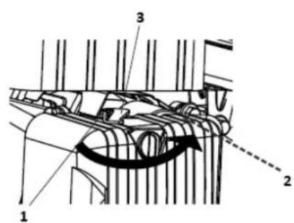
text_image
Technical diagram of a mechanical component with numbered parts and an arrow indicating motion or direction.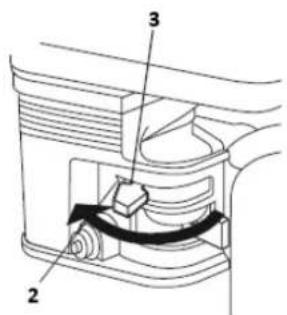
text_image
Technical diagram of a device with labeled parts 2, 3, and internal structure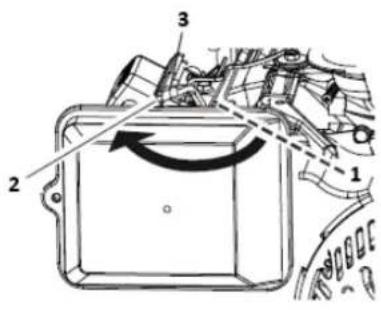
text_image
Technical diagram of a mechanical component with numbered parts and directional arrows indicating motion or flow.1- OPEN
2- CLOSE
3- Choke lever
- Move the throttle lever away from the SLOW position, about 1/3 of the way toward the FAST position.
Some engine applications use a remotely-mounted throttle control rather than the engine-mounted throttle lever shown here.
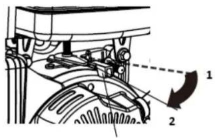
text_image
Technical diagram of a mechanical assembly with labeled parts and directional arrows indicating motion or movement.3
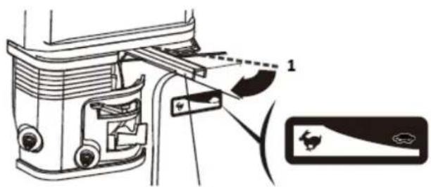
text_image
Technical diagram showing a mechanical assembly with labeled component 1 and a close-up view of a device.3
1- Slow
2- Fast
3- Throttle lever
- Turn the engine switch to the ON position.
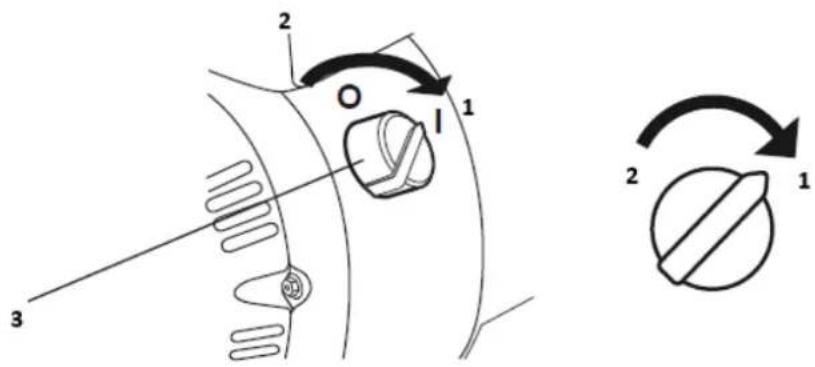
text_image
Technical diagram showing mechanical component with labeled parts and rotation arrows, alongside a circular schematic symbol.1- ON
2- OFF
3- Engine switch
- Operate the starter.
RECOIL STARTER (all engine types):
Pull the starter grip lightly until you feel resistance, then pull briskly.
Return the starter grip gently.
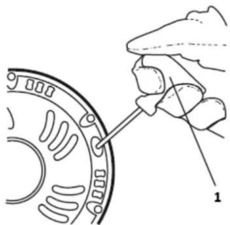
natural_image
Diagram of a hand turning a mechanical component with labeled parts (no text or symbols present)1-Starter grip
- If the choke lever has been moved to the CLOSE position to start the engine, gradually move it to the OPEN position as the engine warms up.
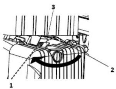
text_image
Technical diagram of a mechanical component with numbered parts and an arrow indicating rotational direction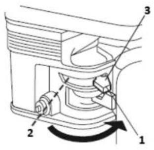
text_image
Technical diagram of a mechanical component with numbered parts and directional arrow indicating rotation or movement.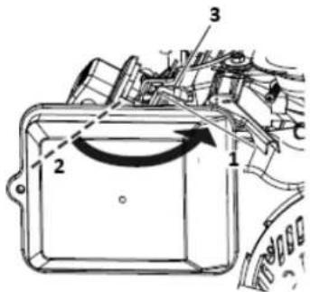
text_image
Technical diagram of a mechanical component with numbered parts and directional arrows indicating motion or flow.1- Open
2- Close
3- Choke lever
Stopping the engine
To stop the engine in an emergency, simply turn the engine switch to the OFF position. Under normal conditions, use the following procedure.
- Move the throttle lever to the SLOW position.
Some engine applications use a remotely-mounted throttle control rather than the engine-mounted throttle lever shown here.

text_image
Technical diagram of a mechanical assembly with numbered components and labeled parts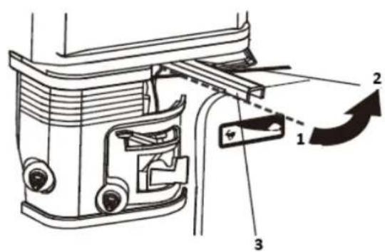
text_image
Technical diagram of a mechanical assembly with numbered components and directional arrows indicating motion or movement.1- Fast
2- Slow
3- Throttle lever
- Turn the engine switch off.
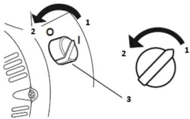
text_image
1 2 O I 2 3 11- ON
2-OFF
3- Engine switch
- Turn the fuel valve lever off.
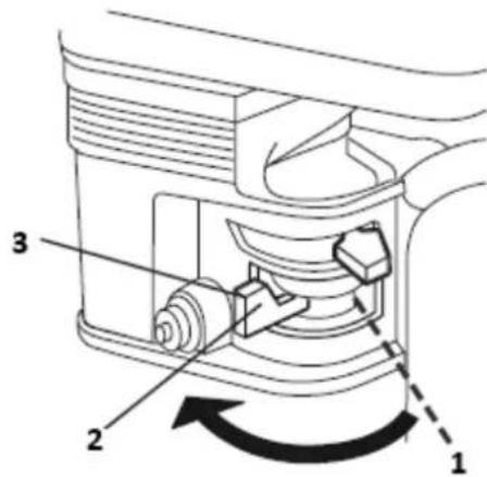
text_image
Technical diagram of a mechanical device with numbered components and directional arrows indicating motion or rotation.1- Open
2- Close
3- Fuel valve lever
Setting engine speed
Position the throttle lever for the desired engine speed.
Some engine applications use a remotely-mounted throttle control rather than the engine-mounted throttle lever shown here.
For engine speed recommendations, refer to the instructions provided with the equipment powered by this engine.
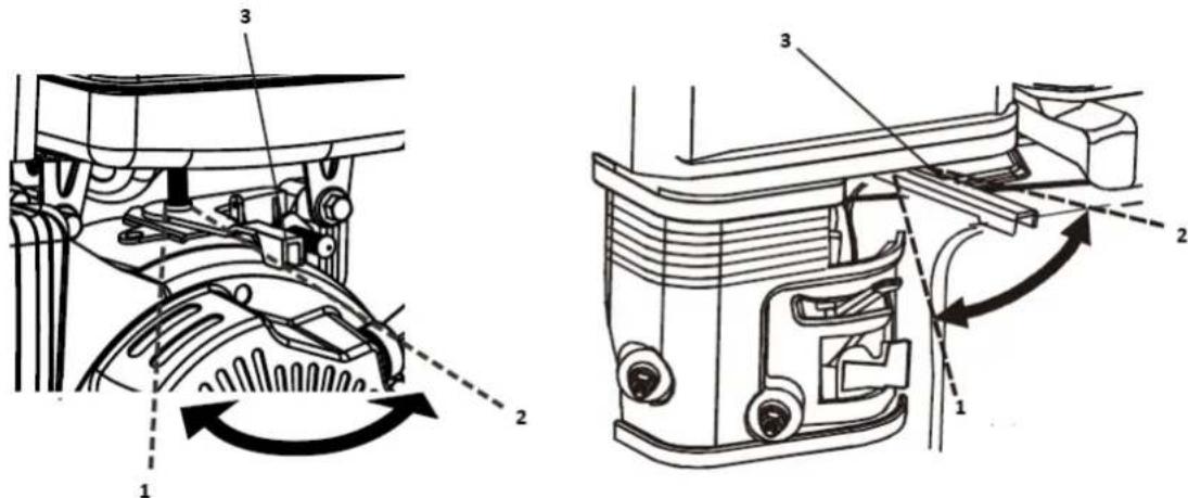
text_image
Technical diagram showing mechanical assembly with numbered components and directional arrows indicating motion or flow.1- Fast
2- Slow
3- Throttle lever
4.5. Maintenance
Importance of maintenance
Good maintenance is essential for safe, economical, and trouble-free operation. It will also help reduce air pollution.

Improperly maintaining this engine, or failure to correct a problem before operation, can cause a malfunction in which you can be seriously hurt or killed.
Always follow the inspection and maintenance recommendations and schedules in this owner's manual.
To help you properly care for your engine, the following pages include a maintenance schedule, routine inspection procedures, and simple maintenance procedures using basic hand tools. Other service tasks that are more difficult, or require special tools, are best handled by professionals and are normally performed by a technician or other qualified mechanic.
The maintenance schedule applies to normal operating conditions. If you operate your engine under unusual conditions, such as sustained high-load or high-temperature operation, or use in unusually wet or dusty conditions, consult your servicing dealer for recommendations applicable to your individual needs and use.
Maintenance safety
Some of the most important safety precautions are as follows: However, we cannot warn you of every conceivable hazard that can arise in performing maintenance. Only you can decide whether or not you should perform a given task.

Failure to properly follow maintenance instructions and precautions can cause you to be seriously hurt or killed. Always follow the procedures and precautions in the owner's manual.
Safety Precautions
- Make sure the engine is off before you begin any maintenance or repairs. This will eliminate several potential hazards:
- Carbon monoxide poisoning from engine exhaust: Be sure there is adequate ventilation whenever you operate the engine.
■ Burns from hot parts: Let the engine and exhaust system cool before touching. -
Injury from moving parts: Do not run the engine unless instructed to do so.
-
Read the instructions before you begin, and make sure you have the tools and skills required.
- To reduce the possibility of fire or explosion, be careful when working around gasoline. Use only a non-flammable solvent, not gasoline, to clean parts. Keep cigarettes, sparks and flames away from all fuel-related parts.
Remember that your servicing dealer knows your engine best and is fully equipped to maintain and repair it.
To ensure the best quality and reliability, use only new, genuine parts or their equivalents for repair and replacement.
Maintenance schedule
| REGULAR SERVICE PERIOD (3)Perform at every indicatedmonth or operating hourinterval, whichever comes first. | Each use | First Monthor 20Hrs | Every 3Monthsor 50 Hrs | Every 6Monthsor 100Hrs | Every Year or300Hrs | |
| Item | ||||||
| Engine Oil | Checklevel | ○ | ||||
| Change | ○ | ○ | ||||
| Air Cleaner | Check | ○ | ||||
| Clean | ○ (1) | |||||
| Replace | ○☆ | |||||
| Sediment Cup | Clean | ○ | ||||
| Spark Plug | Check-adjust | ○ | ||||
| Replace | ○ | |||||
| Spark Arrester(optionalparts) | Clean | ○ | ||||
| Idle Speed Check- | adjust | ○ (2) | ||||
| Valve Clearance | Check-adjust | ○ (2) | ||||
| Fuel Tank & Filter | Clean | ○ (2) | ||||
| Combustion Chamber | Clean | After every 300 Hrs.(2) |
| Fuel Tube | Check | Every 2 years (Replace if necessary) (2) |
- Emission-related items.
☆ Replace the paper element type only.
- Service more frequently when used in dusty areas.
- These items should be serviced by your servicing dealer unless you have the proper tools and are mechanically proficient. Refer to manual for service procedures.
Refuelling
Fuel tank capacities 152F/154F/156F/TR79/TR87/TR98: 1.6 L
168F(E)/168FB(E)/TR196(E): 3.6L
170F(E)/ 170FB(E)/TR212(E) /TR223(E): 3.6L
172F (E)/TR236(E): 3.6L
177F(E)/ TR270(E)/ TR306(E): 6.0L
188F(E)/ TR389(E): 6.0L
190F(E) /192F(E)/TR420(E)/TR440(E)/TR460(E): 6.0L
With the engine stopped, remove the fuel tank cap and check the fuel level. Refill the tank if the fuel level is low.
WARNING
Gasoline is highly flammable and explosive. You can be burned or seriously injured when handling fuel.
- Stop the engine and keep heat, sparks, and flame away.
- Handle fuel only outdoors.
- Wipe up spills immediately.
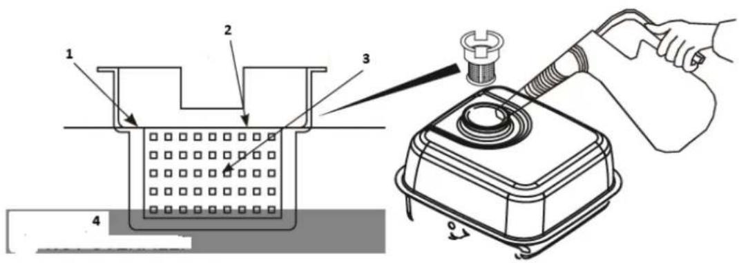
text_image
Technical diagram showing a mechanical assembly with labeled components and a hand holding a tool, likely illustrating a measurement or inspection procedure.1-Maximum fuel level
2-Fuel filler shoulder
3-Fuel filler
4-Max fuel. Do not overfill.
Refuel in a well-ventilated area before starting the engine. If the engine has been running, allow it to cool. Refuel carefully to avoid spilling fuel. Do not fill above the fuel strainer shoulder. After refuelling, tighten the fuel tank cap securely.
Never refuel the engine inside a building where gasoline fumes may reach flames or sparks. Keep gasoline away from appliance pilot lights, barbecues, electric appliances, power tools, etc.
Spilled fuel is not only a fire hazard, it causes environmental damage. Wipe up spills immediately.

Fuel can damage paint and plastic. Be careful not to spill fuel when filling your fuel tank. Damage caused by spilled fuel is not covered under warranty.
FUEL RECOMMENDATIONS
Use unleaded gasoline with a pump octane rating of 86 or higher.
These engines are certified to operate on unleaded gasoline. Unleaded gasoline produces fewer engine and spark plug deposits and extends exhaust system life.
Never use stale or contaminated gasoline or an oil/gasoline mixture. Avoid getting dirt or water in the fuel tank.
Occasionally you may hear a light “spark knock” or “pinging” (metallic rapping noise) while operating under heavy loads. This is no cause for concern.
If spark knock or pinging occurs at a steady engine speed, under normal load, change brands of gasoline. If spark knock or pinging persists, see an authorized servicing dealer.

Running the engine with persistent spark knock or pinging can cause engine damage.
Running the engine with persistent spark knock or pinging is considered misuse, and the Distributor's Limited Warranty does not cover parts damaged by misuse.
ENGINE OIL LEVEL CHECK
Check the engine oil level with the engine stopped and in a level position.
- Remove the filler cap/dipstick and wipe it clean.
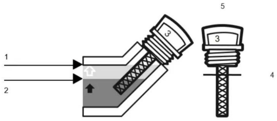
text_image
1 2 3 5 3 41-Upper limit
2-Lower limit
3-Oil
4-Full level
5-Filler cap/dipstick
-
Insert and remove the dipstick without screwing it into the filler neck. Check the oil level shown on the dipstick.
-
If the oil level is low, fill to the edge of the oil filler hole with the recommended oil.
-
Screw in the filler cap/dipstick securely.
Notice
Running the engine with persistent spark knock or pinging can cause engine damage.
The Oil Alert system (applicable engine types:TR79/TR196/TR389) will automatically stop the engine before the oil level falls below safe limit. However, to avoid the inconvenience of an unexpected shutdown, always check the engine oil level before startup.
ENGINE OIL CHANGE
Drain the used oil while the engine is warm. Warm oil drains quickly and completely.
-
Place a suitable container below the engine to catch the used oil, and then remove the filler cap/dipstick and the drain plug. Slant the engine with the angle of a certain degree to help drain more quickly and completely.
-
Allow the used oil to drain completely, and then reinstall the drain plug, and tighten it securely.
Please dispose of used motor oil in a manner that is compatible with the environment. We suggest you take used oil in a sealed container to your local recycling centre or service station for reclamation. Do not throw it in the trash; pour it on the ground; or down a drain.
- With the engine in a level position, fill to the outer edge of the oil filler hole with the recommended oil.
Engine oil capacities:
152F/154F/156F/TR79/TR87/TR98:0.4L
160F(E)/168F(E)/168FB(E)/TR163(E)/TR196(E): 0.6L
170F(E)/ 170FB(E)/TR212(E) /TR223(E): 0.6L
172F (E)/TR236(E): 0.6L
177F(E)/TR270(E)/TR306(E):1.1L
188F(E)/TR389(E): 1.1L
190F(E) / 192F(E) / TR420(E) / TR440(E) / TR460(E): 1.1L
Running the engine with a low oil level can cause engine damage.
The Oil Alert system (applicable engine types) will automatically stop the engine before the oil level falls below the safe limit.
However, to avoid the inconvenience of an unexpected shutdown, fill to the upper limit, and check the oil level regularly.
- Screw in the filler cap/dipstick securely.
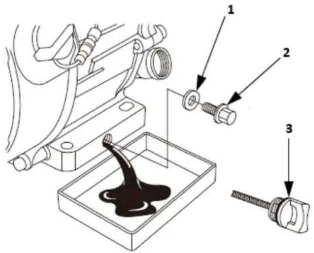
text_image
Technical diagram showing mechanical assembly with labeled parts, including a drain component and three numbered parts.
natural_image
Technical line drawing of a mechanical engine assembly (no text or symbols)1-Sealing washer (Replace)
2-Drain plug
3-Oil filler cap/dipstick
4-Oil level
REDUCTION GEAR OIL (Only on equipped model)
<1/2 reduction with automatic centrifugal clutch>
- Remove the oil filler cap and wipe the dipstick clean.
- Insert the dipstick into the filler neck but do not screw it in.
- If the level is low, fill to the upper level mark with the same oil recommended for the engine.
Oil capacity of TR163/ TR196/ TR270/ TR389/TR420: 500cc
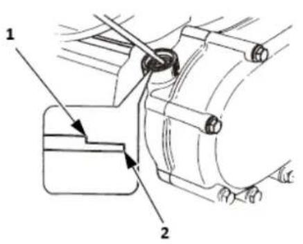
text_image
Technical diagram of a mechanical assembly with labeled parts 1 and 2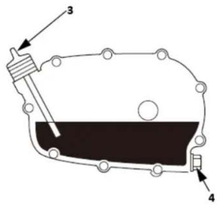
text_image
Technical diagram of a mechanical component with labeled parts 3 and 41-Upper limit
2-Lower limit
3-Oil filler cap/dipstick
4-Drain bolt
SERVICING YOUR ENGINE
ENGINE OIL RECOMMENDATIONS
Oil is a major factor affecting performance and service life. Use 4-stroke automotive detergent oil.
SAE 10W-30 is recommended for general use. Other viscosities shown in the chart may be used when the average temperature in your area is within the recommended range.
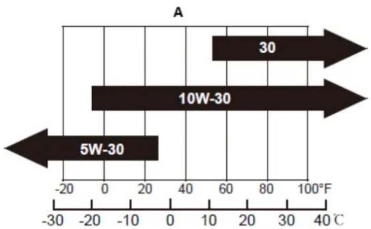
bar
| Temperature Range | Value | | :--- | :--- | | 5W-30 | -25 | | 10W-30 | -10 | | 30 | 60 |B
A-SAE Viscosity grades
B-Average outdoor temperature
AMBIENT TEMPERATURE
The SAE oil viscosity and service classification are in the API label on the oil container. We recommend that you use API SERVICE Category SE or SF oil.
AIR FILTER INSPECTION
Remove the air cleaner cover and inspect the filter. Clean or replace dirty filter elements.
Always replace damaged filter elements. If equipped with an oil-bath air cleaner(equipped only for engine model TR163/TR196/TR212), also check the oil level.
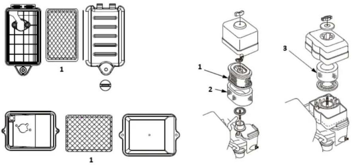
text_image
Technical diagram showing exploded and assembled views of a mechanical device with labeled components1-Paper filter element
2-Foam filter element
3-Air filter element
AIR CLEANER SERVICE
A dirty air filter will restrict air flow to the carburettor, reducing engine performance.
If you operate the engine in very dusty areas, clean the air filter more often than specified in the MAINTENANCE SCHEDULE.

Operating the engine without an air filter, or with a damaged air filter, will allow dirt to enter the engine, causing rapid engine wear. This type of damage is not covered by the Distributor's Limited Warranty.
Dual-Filter-Element Types Applicable for Engine Model:
TR163/TR196/TR212/TR223/TR236C/TR270/TR306, TR389/TR420/TR440/TR460/TR479
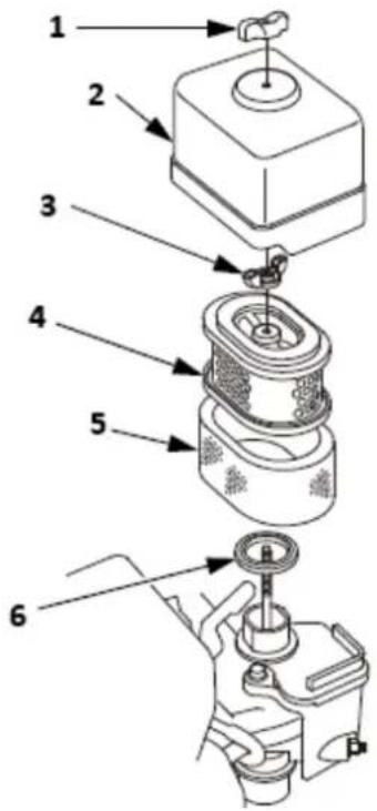
text_image
Technical diagram of a mechanical assembly with numbered parts, likely illustrating a valve or pump mechanism.1-Wing nut
2-Air cleaner cover
3-Wing nut
4-Paper filter element
5-Foam filter element
6-Gasket
- Remove the wing nut from the air cleaner cover and remove the air cleaner cover.
- Remove the wing nut from the air filter and remove the filter.
- Remove the foam filter from the paper filter.
- Inspect both air filter elements and replace them if they are damaged. Always replace the paper air filter element at the scheduled interval.
- Clean the air filter elements if they are to be reused. Paper air filter element: Tap the filter element several times on a hard surface to remove dirt or blow compressed air [not exceeding 30 psi (207 kPa)] through the filter element from the inside. Never try to brush off dirt; brushing will force dirt into the fibres.
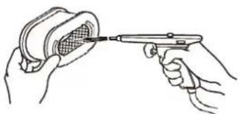
natural_image
Illustration of two hands holding a handheld device, one emitting a mesh-like structure (no text or symbols)Foam air filter element: Clean in warm soapy water, rinse, and allow drying thoroughly. Or clean in non-flammable solvent and allow drying. Dip the filter element in clean engine oil, and then squeeze out all excess oil. The engine will smoke when started if too much oil is left in the foam.
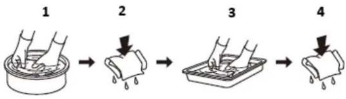
flowchart
graph LR
    A["1 Hand washing in a bowl"] --> B["2 Drop drop"]
    B --> C["3 Hand washing in a tray"]
    C --> D["4 Drop drop"]
1-Clean
2-Squeeze and dry. Do not twist
3-Dip in oil
4-Squeeze. Do not twist.
-
Wipe dirt from the inside of the air cleaner base and cover, using a moist rag. Be careful to prevent dirt from entering the air duct that leads to the carburettor.
-
Place the foam air filter element over the paper element, and reinstall the assembled air filter. Be sure the gasket is in place beneath the air filter. Tighten the air filter wing nut securely.
-
Install the air cleaner cover, and tighten the cover wing nut securely.
Oil-Bath Type (equipped only for engine model TR163/TR196/TR212):
- Remove the wing nut, and remove the air cleaner cap and cover.
- Remove the air filter from the cover, Wash the cover and filter in warm, soapy water, rinse, and allow drying thoroughly. Or clean in non-flammable solvent and allow drying.
- Dip the filter in clean engine oil, and then squeeze out all excess oil. The engine will smoke if too much oil is left in the foam.
- Empty the used oil from the air cleaner case, wash out any accumulated dirt with non-flammable solvent, and dry the case.
- Fill the air cleaner case to the OIL LEVEL mark with the same oil that is recommended for the engine. Oil capacity: 60 cm
- Reassemble the air cleaner and tighten the wing nut securely.
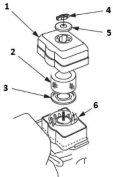
text_image
Technical diagram of a mechanical assembly with numbered parts for identification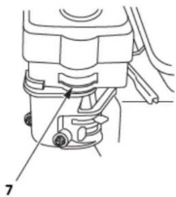
natural_image
Technical line drawing of a mechanical component with labeled parts (no text or symbols present)1-Air cleaner cover
2-Air filter element
3-Grid
4-Wing nut
5-Cap
6-Air cleaner case
7-Oil level
SEDIMENT CUP CLEANING
- Move the fuel valve to the OFF position, and then remove the fuel sediment cup and O-ring.

Gasoline is highly flammable and explosive. You can be burned or seriously injured when handling fuel.
- Keep heat, sparks and flame away.
- Handle fuel only outdoors.
• Wipe up spills immediately. -
Start the engine more than 3 meters away from the place of refuelling.
-
Wash the sediment cup and O-ring in non-flammable solvent and dry them thoroughly.
- Place the O-ring in the fuel valve and install the sediment cup. Tighten the sediment cup securely.
- Move the fuel valve to the ON position, and check for leaks. Replace the O-ring if there is any leakage.
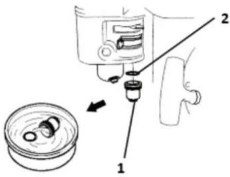
text_image
Diagram showing a mechanical device with labeled parts, including a piston and valve assembly.1-Sediment cap
2-O ring
SPARK PLUG SERVICE
Recommended spark plugs:
E6RTC/E6TC:152F/154F/156F/TR79/TR87/TR98
F6RTC/F6TC:160F(E)/168F(E)/168FB(E)/TR163(E)/TR196(E)170F(E)/170FB(E)
/TR212(E)/TR223(E)/172F(E)/TR236(E)/177F(E)/TR270(E)/188F(E)/190F(E)/
190FB(E)/192F(E)/194F(E)/TR389(E)/TR420(E)/TR440(E)/TR460(E)/TR479(E)
Or other equivalents.
| F6RTC | F7RTC | |
| CHAMPION | RN6YC/RN6Y | RN7YC/RN7Y |
| NGK | BPR6ES | BPR7ES |
| DENSO | W20EPR_U | W22EPR_U |
| BOSCH | WR7DC | WR5DC |

An incorrect spark plug can cause engine damage.
- Disconnect the spark plug cap, and remove any dirt from around the spark plug area.
- Remove the spark plug with a spark plug wrench.
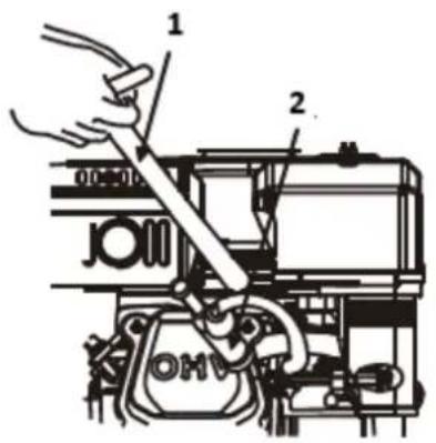
text_image
Technical diagram showing a hand operating a mechanical device with labeled parts 1 and 2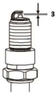
text_image
31- Spark plug wrench
2- Spark plug cap
3-0.70-0.80mm
- Inspect the spark plug. Replace it if the electrodes are worn, or if the insulator is cracked or chipped.
- Measure the spark plug electrode gap with a suitable gauge.
The gap should be 0.028 in -0.031 in (0.70 mm - 0.80 mm). Correct the gap, if necessary, by carefully bending the side electrode.
- Install the spark plug carefully, by hand, to avoid cross-threading.
- After the spark plug seats, tighten with a spark plug wrench to compress the water. If reinstalling the used spark plug, tighten 1/8 - 1/4 turn after the spark plug seats. If installing a new spark plug, tighten 1/2 turn after the spark plug seats.
Notice
A loose spark plug can overheat and damage the engine.
Over tightening the spark plug can damage the threads in the cylinder head.
- Attach the spark plug cap.
IDLE SPEED ADJUSTMENT
- Start the engine outdoors and allow it to warm up to operating temperature.
- Move the throttle lever to its slowest position.
- Turn the throttle stop screw to obtain the standard idle speed. Standard idle speed: 1,400±150 rpm
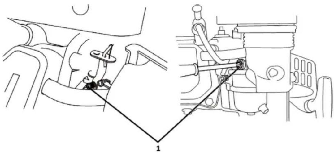
natural_image
Technical line drawing of a mechanical assembly showing internal components and a close-up view (no text or symbols)1-Throttle stop screw
SPARK ARRESTER SERVICE (optional equipment)
Your engine is not factory-equipped with a spark arrester. In some areas, it is illegal to operate an engine without a spark arrester. Check local laws and regulations. A spark arrester is available from authorized servicing dealers.
The spark arrester must be serviced every 100 hours to keep it functioning as designed.
If the engine has been running, the muffler will be very hot. Allow the muffler to cool before servicing the spark arrester.
- Remove the three 4 mm screws from the exhaust deflector and remove the deflector.
- Remove the four 5 mm screws from the muffler protector and remove the muffler protector.
- Remove the 4mm screw from the spark arrester and remove the spark arrester from the muffler.
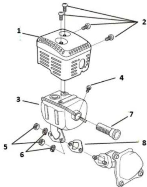
text_image
Exploded view diagram of an electrical component with numbered parts for identification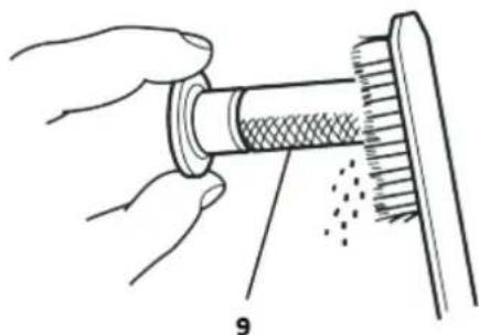
natural_image
Illustration of hands performing a mechanical assembly with a cylindrical component and textured surface (no text or symbols)1-Muffler protector
2-5mm screws
3-Muffler
4-4mm screw
5-8mm nuts
6-Spring washer
7-Spark arrester
8-Gasket
9-Screen
- Use a brush to remove carbon deposits from the spark arrester screen. Be careful to avoid damaging the screen.
The spark arrester must be free of breaks and holes. Replace the spark arrester if it is damaged.
- Install the spark arrester, muffler protector, and exhaust deflector in the reverse order of disassembly.

Never use an engine without an appropriate spark arrester in the forest areas! Doing so may cause a fire!
4.6. Storage / Transporting
Storing your engine
Storage Preparation
Proper storage preparation is essential for keeping your engine trouble free and looking good. The following steps will help to keep rust and corrosion from impairing your engine's function and appearance and will make the engine easier to start after storage.
Cleaning
If the engine has been running, allow it to cool for at least half an hour before cleaning. Clean all exterior surfaces, touch up any damaged paint, and coat other areas that may rust with a light film of oil.

Using a garden hose or pressure washing equipment can force water into the air cleaner or muffler opening. Water in the air cleaner will soak the air filter, and water that passes through the air filter or muffler can enter the cylinder, causing damage.
Water contacting a hot engine can cause damage. If the engine has been running, allow it to cool for at least half an hour before washing.
Fuel
Gasoline will oxidize and deteriorate in storage. Old gasoline will cause hard starting, and it leaves gum deposits that clog the fuel system. If the gasoline in your engine deteriorates during storage, you may need to have the carburettor and other fuel system components serviced or replaced.
Gasoline is a mixture of different material. Gasoline left in fuel tank and carburettor will cause functional problems. The causing time varies under different factors, such as storing temperature, fuel tank partially or filled. The air in the tank can cause fuel deterioration when fuel tank is partially filled. High storing temperature accelerates fuel deterioration. Fuel deterioration may occur within a few months or even less, when the gasoline is not fresh during refuelling.
The Distributor's Limited Warranty does not cover fuel system damage or engine performance problems resulting from neglected storage preparation.
You can extend fuel storage life by adding a fuel stabilizer that is formulated for that purpose, or you can avoid fuel deterioration problems by draining the fuel tank and carburettor.
Adding a fuel stabilizer to extend fuel storage life
When adding a fuel stabilizer, fill the fuel tank with fresh gasoline. If only partially filled, the air in the tank will promote fuel deterioration during storage. If you keep a container of gasoline for refuelling, be sure that it contains only fresh gasoline.
-
Add fuel stabilizer following the manufacturer's instructions.
-
After adding a fuel stabilizer, run the engine outdoors for 10 minutes to be sure that treated gasoline has replaced the untreated gasoline in the carburettor.
-
Stop the engine and move the fuel valve to the "OFF" position.
Draining the fuel tank and carburettor
-
Place an approved gasoline container below the carburettor and use a funnel to avoid spilling fuel.
-
Remove the carburettor drain bolt and sediment cup, and then move the fuel valve lever to the ON position.
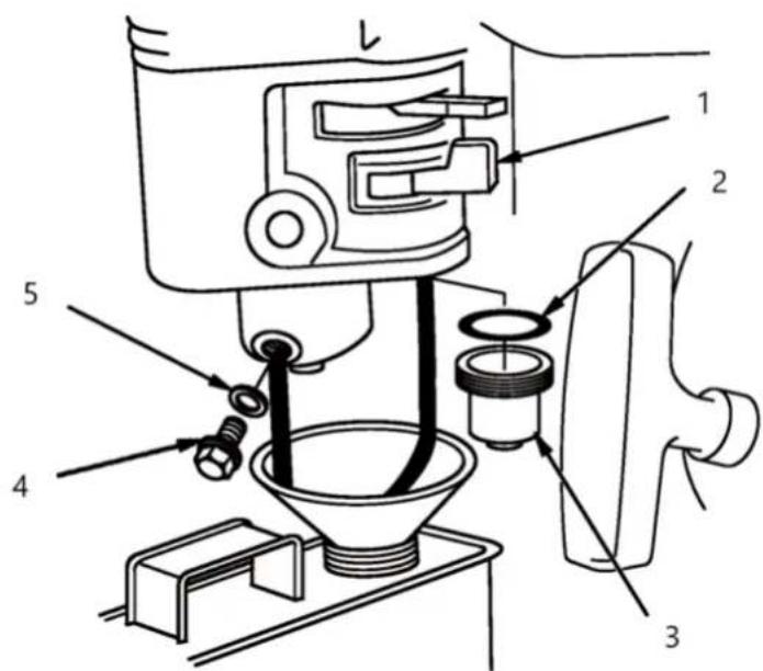
text_image
Technical diagram of a coffee maker with labeled parts including feeding, drying, and cleaning steps1- Fuel valve lever
2- O-Ring
3- Sediment cup
4- Drain bolt
5- Washer
- After all the fuel has drain into the container, reinstall the drain bolt and sediment cup. Tighten them securely.
Storage Precautions
- Change the engine oil.
- Remove the spark plugs.
- Pour a tablespoon (5-10 cc) of clean engine oil into the cylinder.
- Pull the starter rope several times to distribute the oil in the cylinder.
-
Reinstall the spark plugs.
-
Pull the starter rope slowly until resistance is felt. This will close the valves so moisture cannot enter the engine cylinder. Return the starter rope gently.
If your engine will be stored with gasoline in the fuel tank and carburettor, it is important to reduce the hazard of gasoline vapor ignition. Select a well-ventilated storage area away from any appliance that operates with a flame, such as a furnace, water heater, or clothes dryer. Also avoid any area with a spark-producing electric motor, or where power tools are operated.
If possible, avoid storage areas with high humidity, because that promotes rust and corrosion.
Unless all fuel has been drained from the fuel tank, leave the fuel valve lever in the OFF position to reduce the possibility of fuel leakage.
Position the equipment so the engine is level. Tilting can cause fuel or oil leakage.
With the engine and exhaust system cool, cover the engine to keep out dust. A hot engine and exhaust system can ignite or melt some materials. Do not use sheet plastic as a dust cover. A nonporous cover will trap moisture around the engine, promoting rust and corrosion.
If equipped with a battery for an electric starter, recharge the battery once a month while the engine is in storage. This will help to extend the service life of the battery.
Removal from Storage
Check your engine as described in the chapter CHECK BEFORE OPERATION.
If the fuel was drained during storage preparation, fill the tank with fresh gasoline. If you keep a container of gasoline for refuelling, be sure that it contains only fresh gasoline. Gasoline oxidizes and deteriorates over time, causing hard starting.
If the cylinders were coated with oil during storage preparation, the engine may smoke briefly at startup. This is normal.
Transporting
If the engine has been running, allow it to cool for at least 15 minutes before loading the engine-powered equipment on the transport vehicle. A hot engine and exhaust system can burn you and can ignite some materials.
Keep the engine level when transporting to reduce the possibility of fuel leakage. Move the fuel valve lever to the "OFF" position.
4.7. Troubleshooting
| Engine Will Not Start | Possible Cause | Correction |
| 1. Electric starting: check battery. | Battery discharged. | Recharge battery. |
| 2. Check control positions. | Fuel valve OFF. | Move lever to ON. |
| Choke OPEN. | Move lever to CLOSE unless engine is warm. | |
| Engine switch OFF. | Turn engine switch to ON. | |
| 3. Check fuel. | Out of fuel. | Refuel. |
| Bad fuel; engine stored without treating or draining gasoline, or refuelled with bad gasoline. | Drain fuel tank and carburettor. Refuel with fresh gasoline. | |
| 4. Remove and inspect spark plugs. | Spark plugs faulty, fouled, or improperly gapped. | Gap, or replace spark plugs. |
| Spark plugs wet with fuel (flooded engine). | Dry and reinstall spark plugs. Start engine with throttle lever in FAST position. | |
| 5. Take engine to an authorized servicing dealer, or refer to manual. | Fuel filter clogged, carburettor malfunction, ignition malfunction, valve stuck, etc. | Replace or repair faulty components as necessary. |
| Engine Lacks Power | Possible Cause | Correction |
| 1. Check air filter. Filter element(s) clogged. | Clean or replace filter element(s). | |
| 2. Check fuel. | Out of fuel. | Refuel. |
| Bad fuel; engine stored without treating or draining gasoline, or refuelled with bad gasoline. | Drain fuel tank and carburettor. Refuel with fresh gasoline. | |
| 3. Take engine to an authorized servicing dealer, or refer to the manual. | Fuel filter clogged, carburettor malfunction, ignition malfunction, valve stuck, etc. | Replace or repair faulty components as necessary. |
4.8. Technical & consumer information
Technical information
Serial Number Location
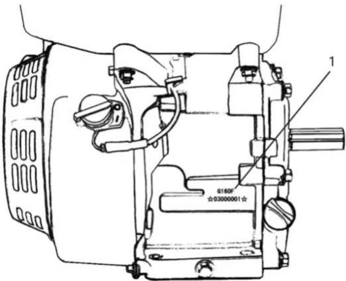
text_image
0160F ☆03000001☆1- Engine type serial number
Record the engine serial number in the space below. You will need this serial number when ordering parts, and when making technical or warranty inquires.
Engine serial number: ____
Battery Connections for Electric Starter
Use a 12-volt battery with an ampere-hour rating of at least 18 Ah.
Be careful not to connect the battery in reverse polarity, as this will short circuit the battery charging system. Always connect the positive (+) battery cable to the battery terminal before connecting the negative (-) battery cable, so your tools cannot cause a short circuit if they touch a grounded part while tightening the positive (+) battery cable end.

WARNING! A battery can explode if you do not follow the correct procedure, seriously injuring anyone nearby. Keep all sparks, open flames, and smoking materials away from the battery.
- Connect the battery positive (+) cable to the starter solenoid terminal as shown.
- Connect the battery negative (-) cable to an engine mounting bolt, frame bolt, or other good engine ground connection.
- Connect the battery positive (+) cable to the battery positive (+) terminal as shown.
- Connect the battery negative (-) cable to the battery negative (-) terminal as shown.
- Coat the terminals and cable ends with grease.
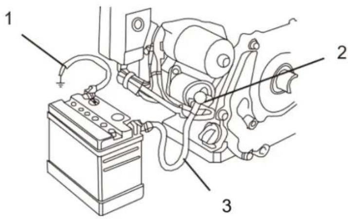
text_image
Technical diagram of an automotive battery assembly with labeled parts 1, 2, and 31- NEGATIVE(-) BATTERY CABLE
2- STARTER SOLENOID
3- POSITIVE(+) BATTERY CABLE
Remote Control Linkage
The throttle and choke control levers are provided with holes for optional cable attachment. The following illustrations show installation examples for a solid wire cable and for a flexible, braided wire cable. If using a flexible, braided wire cable, add a return spring as shown. It is necessary to loosen the throttle lever friction nut when operating the throttle with a remotely-mounted control.
160F(E)/168F(E)/168F-1(E)/170F(E)/172F(E)/TR163(E)/TR196(E)/TR212(E)/TR223(E)/TR236(E)
REMOTE THROTTLE LINKAGE
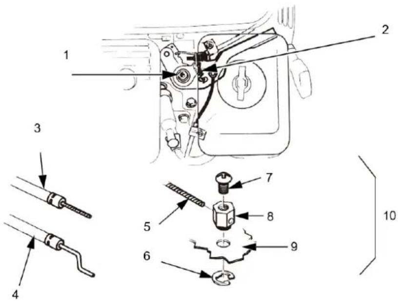
text_image
Technical diagram of a mechanical assembly with numbered parts and exploded view, likely for assembly or maintenance instructions.1- THROTTLE LEVER FRICTION NUT
2- RETURN SPRING
3- FLEXIBLE WIRE CORE MOUNTING
4- SOLID WIRE CORE MOUNTING
5- WIRE
6- 5 mm CIRCLIP
7- 4 mm SCREW
8- WIRE HOLDER
9- THROTTLE LEVER
10- OPTIONAL
REMOTE CHOKE LINKAGE
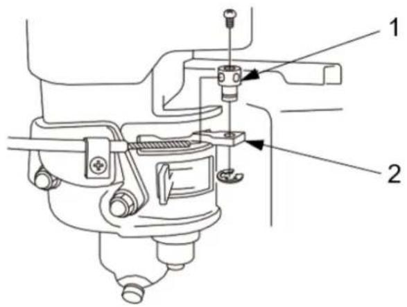
text_image
Technical diagram of a mechanical assembly with labeled parts 1 and 21- WIRE HOLDER
2-CHOKE LEVER
177F(E)/TR270(E),188F(E)/190F(E)/TR389(E)/TR420(E) /TR440(E)/TR460(E)/TR479(E)
REMOTE THROTTLE LINKAGE

text_image
Technical diagram of a mechanical assembly with numbered parts, likely for repair or maintenance instructions.1- THROTTLE LEVER FRICTION NUT
2- FLEXIBLE WIRE CORE MOUNTING
3- SOLID WIRE CORE MOUNTING
4- WIRE
5- 5 mm CIRCLIP
6-4 MM SCREW
7- WIRE HOLDER
8- THROTTLE LEVER
9- OPTIONAL
REMOTE CHOKE LINKAGE
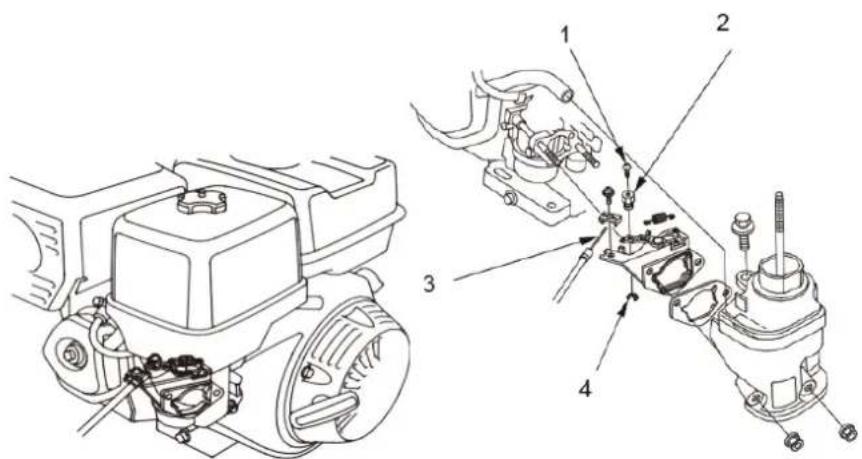
text_image
Technical diagram showing mechanical assembly with numbered components for maintenance or repair1- 4 mm SCREW
2- WIRE HOLDER
3- WIRE
4- 5 mm CIRCLIP
Carburettor Modification for High Altitude Operation
At high altitude, the standard carburettor air-fuel mixture will be too rich. Performance will decrease, and fuel consumption will increase. A very rich mixture will also foul the spark plug and cause hard starting. Operation at an altitude that differs from that at which this engine was certified, for extended periods of time, may increase emissions.
High altitude performance can be improved by specific modifications to the carburettor. If you always operate your engine at altitudes above 5,000 feet (1,500 meters), have your servicing dealer perform this carburettor modification. This engine, when operated at high altitude with the carburettor modifications for high altitude use, will meet each emission standard throughout its useful life.
Even with carburettor modification, engine horsepower will decrease about 3.5% for each 1,000-foot (300-meter) increase in altitude. The effect of altitude on horsepower will be greater than this if no carburettor modification is made.
Notice:
When the carburettor has been modified for high altitude operation, the air-fuel mixture will be too lean for low altitude use. Operation at altitudes below 5,000 feet (1,500 meters) with a modified carburettor may cause the engine to overheat and result in serious engine damage. For use at low altitudes, have your servicing dealer return the carburettor to original factory specifications.
Oxygenated Fuels
Some conventional gasolines are being blended with alcohol or an ether compound. These gasolines are collectively referred to as oxygenated fuels. To meet clean air standards, some areas use oxygenated fuels to help reduce emissions.
If you use an oxygenated fuel, be sure it is unleaded and meets the minimum octane rating requirement.
Before using an oxygenated fuel, try to confirm the fuel's contents. Some areas require this information to be posted on the pump.
The following are the EPA approved percentages of oxygenates:
| ETHANOL | (ethyl or grain alcohol) 10% by volume You may use gasoline containing up to 10% ethanol by volume. Gasoline containing ethanol may be marketed under the name “Gasohol”. |
| MTBE | (methyl tertiary butyl ether) 15% by volume You may use gasoline containing up to 15% MTBE by volume. |
| METHANOL | (methyl or wood alcohol) 5% by volume You may use gasoline containing up to 5% methanol by volume, as long as it also contains cosolvents and corrosion inhibitors to protect the fuel system. Gasoline containing more than 5% methanol by volume may cause starting and/or performance problems. It may also damage metal, rubber, and plastic parts of your fuel system. |
If you notice any undesirable operating symptoms, try another service station, or switch to another brand of gasoline.
Fuel system damage or performance problems resulting from the use of an oxygenated fuel containing more than the percentages of oxygenates mentioned above are not covered under warranty.
Emission Control System Information
Source of Emissions
The combustion process produces carbon monoxide, oxides of nitrogen, and hydrocarbons. Control of hydrocarbons and oxides of nitrogen is very important because, under certain conditions, they react to form photochemical smog when subjected to sunlight. Carbon monoxide does not react in the same way, but it is toxic.
This utilizes lean carburettor settings and other systems to reduce the emissions of carbon monoxide, oxides of nitrogen and hydrocarbons.
Tampering and Altering Tampering with or altering the emission control system may increase emissions beyond the legal limit. Among those acts that constitute tampering are:
- Removal or alteration of any part of the intake, fuel or exhaust systems.
- Altering or defeating the governor linkage or speed-adjusting mechanism to cause the engine to operate outside its design parameters.
Problems That May Affect Emissions
If you are aware of any of the following symptoms, have your engine inspected and repaired by your servicing dealer.
• Hard starting or stalling after starting.
- Rough idle.
- Misfiring or backfiring under load.
• Afterburning (backfiring).
- Black exhaust smoke or high fuel consumption.
Replacement Parts
The emission control systems on your engine were designed, built. We recommend the use of genuine parts whenever you have maintenance done. These original-design replacement parts are manufactured to the same standards as the original parts, so you can be confident of their performance. The use of replacement parts that are not of the original design and quality may impair the effectiveness of your emission control system.
A manufacturer of an aftermarket part assumes the responsibility that the part will not adversely affect emission performance. The manufacturer or rebuilder of the part must certify that use of the part will not result in a failure of the engine to comply with emission regulations.
Maintenance
Follow the maintenance schedule. Remember that this schedule is based on the assumption that your machine will be used for its designed purpose. Sustained high-load or high-temperature operation, or use in unusually wet or dusty conditions, will require more frequent service.
Engine Tune-up
| ITEM | SPECIFICATION |
| Spark plug gap | 0.028-0.031 in (0.70 mm -0.80 mm) |
| Valve clearance | IN: 0.15 mm±0.02 mm (cold)EX: 0.20 mm±0.02 mm (cold) |
| Other specifications | No other adjustments needed |
CONSUMER INFORMATION
Publications
These publications will give you additional information for maintaining and repairing your engine. You may order them from your engine dealer.
Parts Catalog
This manual provides complete, illustrated parts lists.
QUICK REFERENCE INFORMATION
| Engine Oil | Type | SAE 10W-30,API SE or SF, for general use |
| Capacity | 1. 152F/154F/156F/TR79/TR87/TR98: 0.4L2. 160F(E)/168F(E)/168FB(E)/TR163(E)/TR196(E): 0.6L3. 170F(E)/ 170FB(E)/TR212(E) /TR223(E): 0.6L4. 172F (E)/TR236(E): 0.6L5. 177F(E)/TR270(E)/TR306(E): 1.1L6. 188F(E)/TR389(E): 1.1L7. 190F(E) /192F(E)/TR420(E)/TR440(E)/TR460(E): 1.1L | |
| Spark Plug | Type | E6RTC/E6TC:152F/154F/156F/TR79/TR87/TR98F6RTC/F6TC:160F(E)/168F(E)/168FB(E)/TR163(E)/TR196(E)170F (E)/170FB(E)TR212(E)/TR223(E)/172F(E)/TR236(E)/177F(E)/TR270(E)/ 188F(E)/190F(E)/190FB(E)/192F(E)/194F(E)/TR389(E)/TR420(E)/TR440(E)/TR460(E)/TR 479(E)or other equivalents. |
| Gap | 0.028—0.031 in (0.70 mm—0.80 mm) | |
| Carburettor | Idle speed | 1400 rpm±150 rpm |
| Maintenance | Each use | Check engine oil. Check air filter. |
| First 20 hours | Change engine oil. | |
| Subsequent | Refer to the maintenance |
4.9. Specifications
| Model | TR79 | TR87 | TR98 |
| Type | Single cylinder, 4-Stroke, Forced Air Cooling, OHV | ||
| Rated Power(kW/3600rpm) | 1.5 | 1.65 | 1.7 |
| Max. Torque(Nm/rpm) | 3.9/3000 | 4.3/3000 | 4.8/3000 |
| Fuel Consumption(g/kWh) | ≤450 | ||
| Idle Speed | 1800±200 | ||
| Speed Fluctuating Ratio | ≤10% | ||
| Noise (≤) | 65db(A) | ||
| Bore × Stroke(mm) | 52×37 | 54×38 | 56×40 |
| Displacement(cc) | 79 | 87 | 98 |
| Compression Ratio | 8.5:1 | ||
| Lubricating mode | Splash | ||
| Starting Mode | Recoil start (Recoil start / Electric starting) | ||
| Rotation | Anti-clockwise (from P.T.O. side) | ||
| Valve Clearance | input valve: 0.10 mm ~0.15mm, | ||
| Spark Plug Clearance | 0.7 mm ~0.8mm | ||
| Igniting Mode | Transistorized Magneto Ignition | ||
| Air cleaner | Semi-dry, Oil bath, Foam filter | ||
| Dimension (Length) (mm) | 325 | 325 | 325 |
| Dimension (Width) (mm) | 315 | 315 | 315 |
| Dimension (High) (mm) | 320 | 320 | 320 |
| Net weight(kg) | 9.5 | 10.5 | 11.5 |
| Model TR163(E) | TR196(E) | TR212(E) | TR223(E) | TR236(E) | |
| Type | Single cylinder, 4-Stroke, Forced Air Cooling, OHV | ||||
| Rated Power(kW/3600rpm) | 3.1 | 4.1 | 4.3 | 4.5 | 4.7 |
| Max. Torque (Nm/rpm) | 10.5/3000 | 11.0/3000 | 12.0/3000 | 13.0/3000 | 13.1/3000 |
| Fuel Consumption(g/kWh) | ≤395 | ||||
| Idle Speed | 1800±200 | ||||
| Speed Fluctuating Ratio | ≤10% | ||||
| Noise (≤) | 70db(A) | ||||
| Bore × Stroke(mm) | 68×45 | 68×54 | 70×55 | 70×58 | 72×58 |
| Displacement(cc) | 163 | 196 | 212 | 223 | 236 |
| Compression Ratio | 8.5:1 | ||||
| Lubricating mode | Splash | ||||
| Starting Mode | Recoil start (Recoil start / Electric starting) | ||||
| Rotation | Anti-clockwise (from P.T.O. side) | ||||
| Valve Clearance | input valve: 0.10 mm ~0.15mm, | ||||
| Spark Plug Clearance | 0.7 mm ~0.8mm | ||||
| Igniting Mode | Transistorized Magneto Ignition | ||||
| Air cleaner | Semi-dry, Oil bath, Foam filter | ||||
| Dimension (Length) (mm) | 390 | 390 | 390 | 390 | 395 |
| Dimension (Width) (mm) | 335 | 335 | 335 | 335 | 345 |
| Dimension (High) (mm) | 370 | 370 | 370 | 370 | 370 |
| Net weight(kg) | 15.0 | 16.0 | 16.5 | 17.0 | 17.5 |
| Model | TR270(E) | TR306(E) |
| Type | Single cylinder, 4-Stroke, Forced Air Cooling, OHV | |
| Rated Power(kW/3600rpm) | 5.3 | 6.3 |
| Max. Torque (Nm/rpm) | 16.0/2800 | 18.5/2800 |
| Fuel Consumption(g/kWh) | ≤374 | |
| Idle Speed | 1800±200 | |
| Speed Fluctuating Ratio | ≤10% | |
| Noise (≤) | 80db(A) | |
| Bore × Stroke(mm) | 77×58 | 82×58 |
| Displacement(cc) | 270 | 306 |
| Compression Ratio | 8.2:1 | |
| Lubricating mode | Splash | |
| Starting Mode | Recoil start (Recoil start / Electric starting) | |
| Rotation | Anti-clockwise (from P.T.O. side) | |
| Valve Clearance | input valve: 0.10 mm ~0.15mm, | |
| Spark Plug Clearance | 0.7 mm ~0.8mm | |
| Igniting Mode | Transistorized Magneto Ignition | |
| Air cleaner | Semi-dry, Oil bath, Foam filter | |
| Dimension (Length) (mm) | 480 | 480 |
| Dimension (Width) (mm) | 405 | 405 |
| Dimension (High) (mm) | 460 | 460 |
| Net weight(kg) | 26.0 | 27.0 |
| Model | TR389(E) | TR420(E) | TR440(E) | TR460(E) | TR479(E) |
| Type | Single cylinder, 4-Stroke, Forced Air Cooling, OHV | ||||
| Rated Power(kw/3600rpm) | 7.35 | 8.5 | 9.0 | 10 | 10.5 |
| Max. Torque (Nm/rpm) | 26.5/2800 | 27.8/2800 | 29.5/2800 | 30.7/2800 | 32.0/2800 |
| Fuel Consumption(g/kWh) | ≤374 | ||||
| Idle Speed | 1800±200 | ||||
| Speed Fluctuating Ratio | ≤10% | ||||
| Noise (≤) | 80db(A) | ||||
| Bore × Stroke (mm) | 88×64 | 90×66 | 92×66 | 92×69 | 94×69 |
| Displacement(cc) | 389 | 420 | 439 | 459 | 479 |
| Compression Ratio | 8.0:1 | ||||
| Lubricating mode | Splash | ||||
| Starting Mode | Recoil start (Recoil start / Electric starting) | ||||
| Rotation | Anti-clockwise (from P.T.O. side) | ||||
| Valve Clearance | input valve: 0.10 mm ~0.15mm, | ||||
| Spark Plug Clearance | 0.7 mm ~0.8mm | ||||
| Igniting Mode | Transistorized Magneto Ignition | ||||
| Air cleaner | Semi-dry, Oil bath, Foam filter | ||||
| Dimension (Length) (mm) | 530 | 530 | 530 | 530 | 530 |
| Dimension (Width) (mm) | 430 | 430 | 430 | 430 | 430 |
| Dimension (High) (mm) | 485 | 485 | 485 | 485 | 485 |
| Net weight(kg) | 31.0 | 32.0 | 33.0 | 34.0 | 35.0 |
With oil alert and electric starter
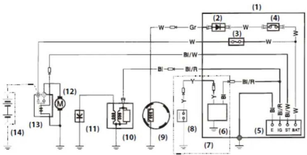
text_image
(1) (2) (4) W Gr W W BI/W BI/R (14) (13) (12) (11) (10) (9) (8) (7) (6) (5) E I G ST BAT BI/R BI/R BI/R| IG | E | BAT | ST | |
| OFF | 0—0 | |||
| ON | ||||
| START | 0—0 |
With oil alert and electric starter
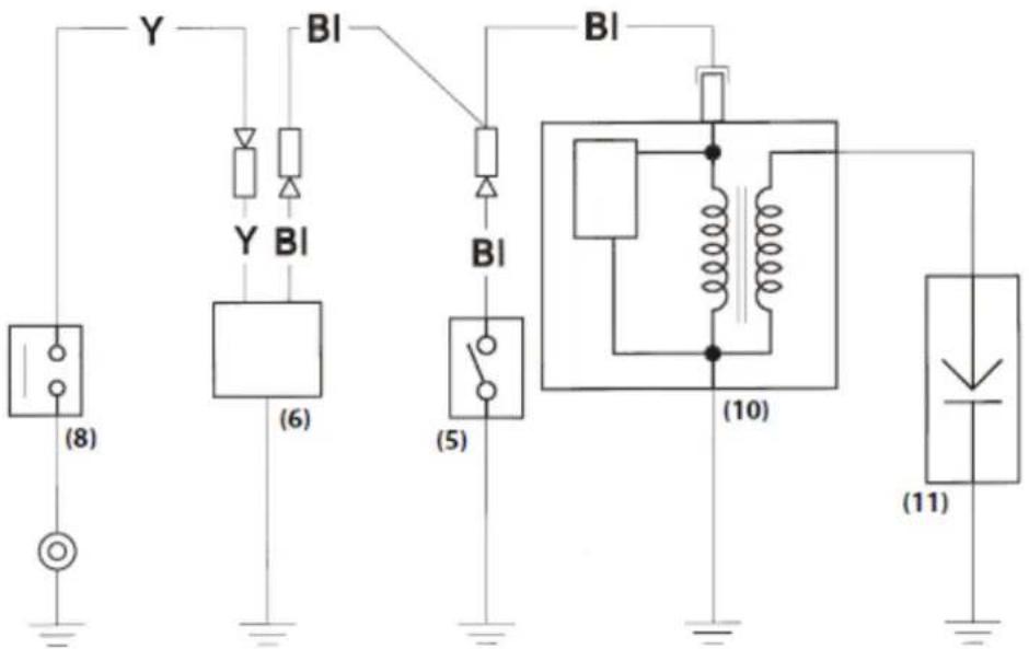
text_image
Y BI Y BI BI (8) (6) (5) (10) (11)| IG | E | |
| OFF | o—o | |
| ON | ||
- Control box
- Rectifier
- Fuse
- Circuit breaker
- Engine switch
- Oil alert unit
- Type with oil alert unit
- Oil level switch
- Changing coil
- Ignition coil
- Spark plug
- Starter motor
- Starter solenoid
- Battery (12V)
| Bl | Black | Br | Brown |
| Y | Yellow | O | Orange |
| Bu | Blue | Lb | Light blue |
| G | Green | Lg | Light green |
| R | Red | P | Pink |
| W | White | Gr | Gray |
4.11. OPTIONAL PARTS
BATTERY
Use a battery rated at 12V, 18Ah or more.
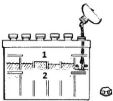
text_image
Diagram of a scientific apparatus with labeled components and a sensor or probe above it1-Upper level
2-Lower level

Do not reverse polarity. Serious damage to the engine and/or battery may occur.

A battery can explode if you do not follow the correct procedure, seriously injuring anyone nearby.
Keep all sparks, open flames, and smoking materials away from the battery.
Check the electrolyte level to be sure that it is between the marks on the case. If the level is below the lower mark, remove the caps and add distilled water to bring the electrolyte level to the upper mark. The cells should be equally full.

text_image
MOC WYLOT 12V~ 15A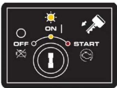
text_image
ON OFF START
flowchart
graph TD
    A["Motor"] --> B["Control Unit"]
    C["Robot Arm"] --> D["Control Unit"]
    E["Lock/Lock System"] --> F["Control Unit"]
    G["Lock System"] --> H["Control Unit"]
    I["5 joysticków"] --> J["Control Unit"]
natural_image
Diagram of two robotic arms with labeled joints, no text or symbols presentnatural_image
Illustration of a magnifying glass examining a document with icons, no text presentRura ręczna
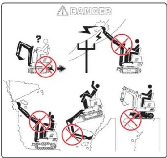
text_image
DANGERtext_image
Diagram illustrating three scenarios of heavy machinery and a person using a car, with corresponding illustrations and labels.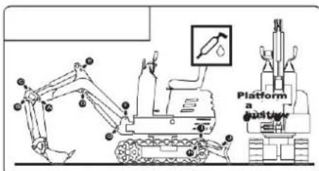
text_image
Platform a gustar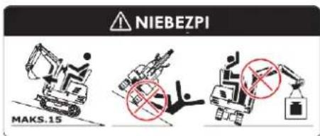
text_image
NIEBEZPI MAKS.15natural_image
Line drawing of an excavator on a power line with visible impact lines (no text or symbols)natural_image
Technical line drawing of an excavator on a sloped terrain (no text or symbols)natural_image
Technical line drawing of an excavator with attached boom and levers (no text or symbols)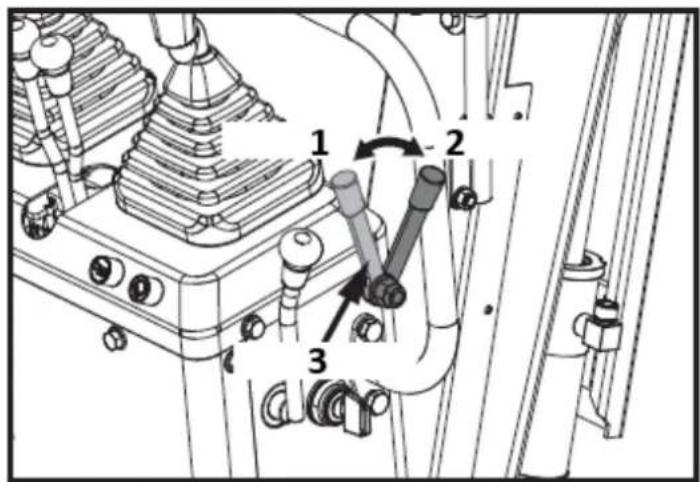
text_image
Technical diagram of a mechanical assembly with numbered components and directional arrows indicating motion or movement.1: Odblokuj
2: Blokada
3: Dźwignia blokady
text_image
Technical diagram of a mechanical assembly with numbered components and directional arrows indicating motion or flow.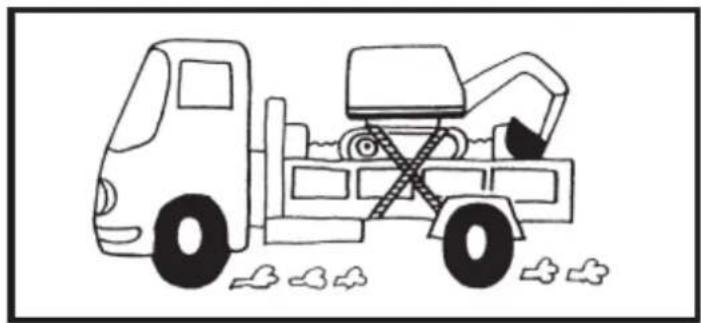
natural_image
Line drawing of a dump truck with an excavator and pile of debris (no text or symbols)natural_image
Diagram of a hand holding a tool with motion arrows indicating movement (no text or symbols)natural_image
Silhouette of a human head with sunglasses and motion arrows, symbolizing vision or perception (no text or symbols)text_image
Technical diagram of a device rear panel with labeled components and directional arrows1

text_image
Two safety symbols: a bird flying over grass and a surveillance camera with smoke.2

text_image
Two safety symbols: a hand crossed out with a prohibition sign and a person with a virus icon.
text_image
Collection of hazard warning symbols and pictograms, including physical contact, safety, and emergency signs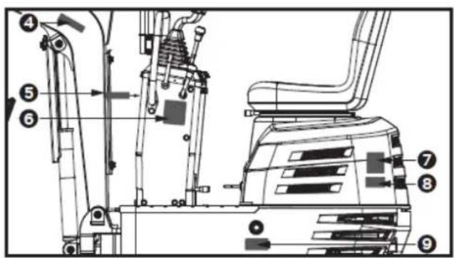
text_image
Technical diagram of an excavator with numbered components for identification and assembly reference.
text_image
4 !
text_image
5 !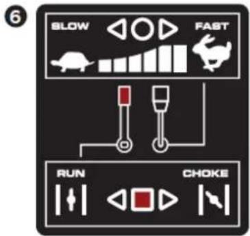
text_image
6 BLOW FAST RUN CHOKE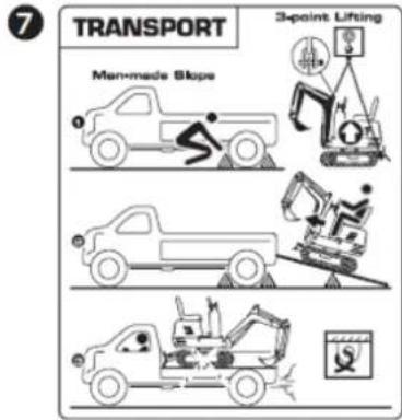
text_image
7 TRANSPORT Man-made Slope 3-point Lifting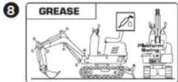
text_image
8 GREASE Platform Swing -0.777 cm
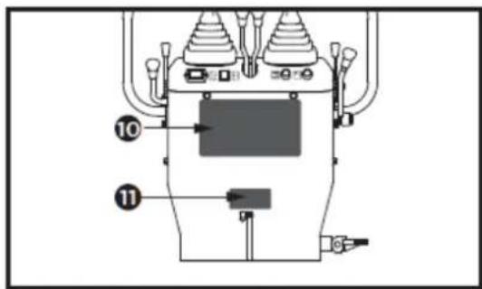
text_image
Technical diagram of a mechanical device with numbered components and labeled parts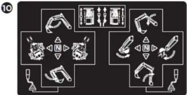
flowchart
graph TD
    A["Robot Arm"] --> B["Tool Icon"]
    B --> C["Control Panel"]
    C --> D["Robot Arm"]
    D --> E["Tool Icon"]
    E --> F["Control Panel"]
    F --> G["Robot Arm"]
    G --> H["Tool Icon"]
    H --> I["Control Panel"]
    I --> J["Robot Arm"]
    J --> K["Tool Icon"]
    K --> L["Control Panel"]
    L --> M["Robot Arm"]
    M --> N["Tool Icon"]
    N --> O["Control Panel"]
    O --> P["Robot Arm"]
    P --> Q["Tool Icon"]
    Q --> R["Control Panel"]
    R --> S["Robot Arm"]
    S --> T["Tool Icon"]
    T --> U["Control Panel"]
11
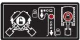
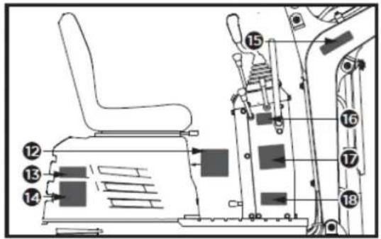
text_image
Technical diagram of an industrial vehicle's internal components with numbered labels pointing to various parts.12
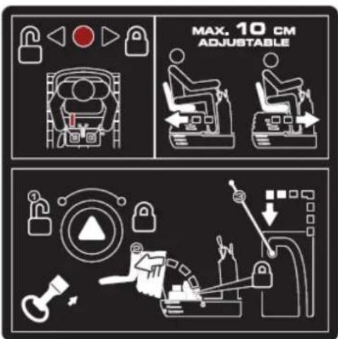
text_image
MAX. 10 CM ADJUSTABLE13
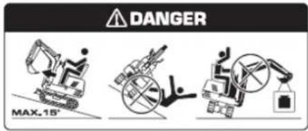
text_image
DANGER MAX.15°14

text_image
DANGER17
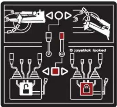
text_image
5 joystick looked18

natural_image
Three diagrams showing mechanical assembly or robotic arm configurations (no text or symbols)15

text_image
Four warning symbols: warning triangle with exclamation mark, triangular warning triangle with broken line, broken line with falling object, and broken line with falling object.16
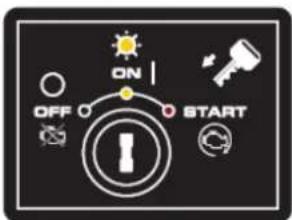
text_image
ON OFF STARTtext_image
Technical diagram of a mechanical device with labeled components and directional arrows indicating flow or movement.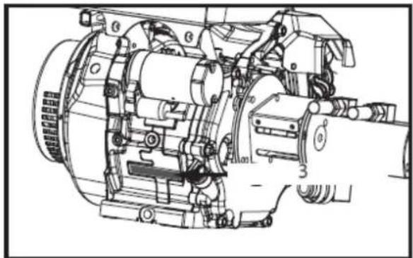
natural_image
Technical line drawing of a mechanical assembly with no visible text or symbolstext_image
Technical diagram showing a mechanical assembly with tool coordinate axes and component layout, including a 1D view and a 2D view.1- Śruba M12 (x1)
text_image
Technical diagram of an excavator with labeled parts including base, guide, and support componentstext_image
1 2 A 24mm 13mm 4mmtext_image
Technical diagram of a mechanical device with labeled parts and a 16mm wrench icon1- Śruba M10x20 (x4)
text_image
X 2 13mm 1 C1- Śruba M8x30 (x4)
natural_image
Technical line drawing of a vehicle's internal components, showing a seat assembly and engine compartment (no text or symbols)text_image
Technical diagram of an excavator with numbered parts for identification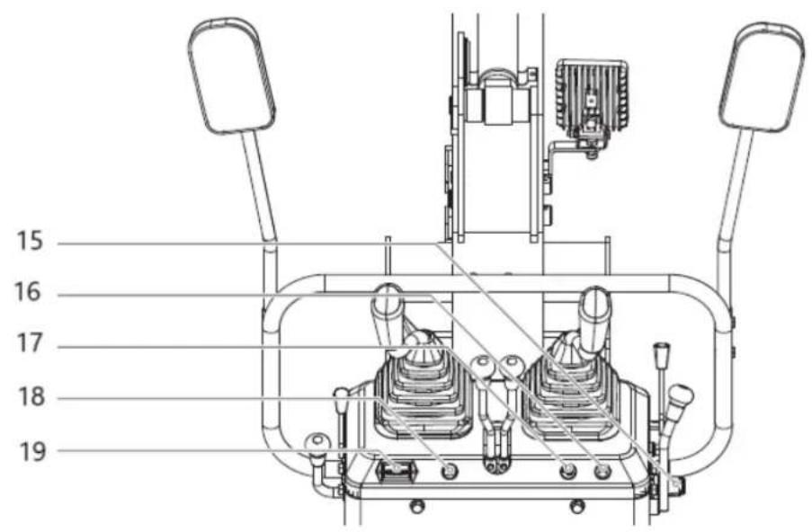
text_image
15 16 17 18 19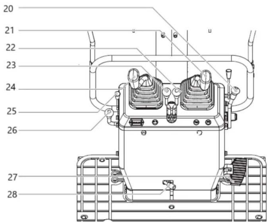
text_image
20 21 22 23 24 25 26 27 28text_image
Technical diagram of a mechanical assembly with numbered components and directional arrows indicating motion or movement.1- Odblokować
2- Blokada
3- Dźwignia blokady
text_image
Technical diagram showing mechanical assembly with numbered components and directional arrows indicating motion or movement.1- Odblokować
2- Blokada
natural_image
Technical line drawing of a mechanical device with no visible text or symbolstext_image
Technical diagram of a mechanical assembly with numbered components and directional arrows indicating motion or movement.1- Zamknięte
2- Zawór paliwa
3- Otwarte
text_image
Technical diagram of a mechanical or electrical component with numbered parts labeled 1 through 7.text_image
Technical diagram showing a mechanical control panel with labeled buttons and indicators, including symbols like '1', '2', and '3'.(1)- WYŁĄCZONY
(2)- WŁĄCZONY
(3)- ROZPOCZNIJ
natural_image
Technical line drawing of a mechanical or electrical component with no visible text or symbolsnatural_image
Technical line drawing of a mechanical device with no visible text or symbols1- Licznik godzin
text_image
Technical diagram of a mechanical assembly with numbered components and directional arrows indicating motion or movement.1- Zamknięte
2- Zawór paliwa
3- Otwarte

text_image
Technical diagram showing a mechanical excavator assembly with labeled parts and a downward arrow indicating process flow.text_image
Technical diagram of a mechanical assembly with numbered components and directional arrows indicating motion or movement.1- Odblokować
2- Blokada
3- Dźwignia blokady
natural_image
Technical line drawing of a mechanical assembly with no visible text or symbolstext_image
Technical diagram of an excavator with labeled parts and directional arrows indicating motion or assembly.natural_image
Technical diagram of a mechanical piping system with valve and valve components (no text or labels)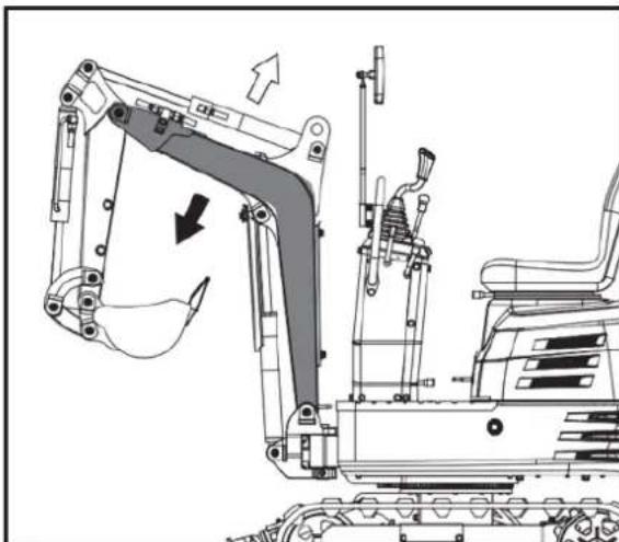
natural_image
Technical line drawing of an excavator assembly with no visible text or symbols
natural_image
Technical diagram of a piping system with valves and a valve (no text or labels)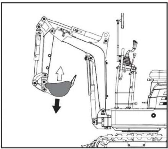
natural_image
Technical line drawing of an excavator with a downward load arrow, showing mechanical components without any text or symbols.OBSŁUGA OBROTOWA (WAHADŁOWA JEDNOSTKI)

UWAGA!
natural_image
Technical diagram of a mechanical piping system with valve and valve components (no text or labels)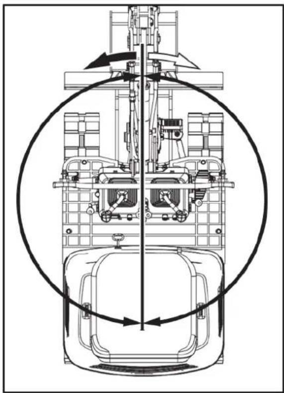
natural_image
Technical line drawing of a mechanical assembly with no visible text or symbolsOPERACJA HUŚTAWANIA WYSIĘGNIKA
text_image
Technical diagram of a mechanical assembly with labeled parts A, B, and numbered components 1 and 21 - Pedat. 2 - PRZÓD

text_image
70° 70°PEDAL BOOM SWING

natural_image
Technical line drawing of a mechanical assembly with no visible text or symbols- Naprawić
OBSŁUGA SPYCHARKI
text_image
Technical diagram of a mechanical assembly with labeled parts A, B, and C, showing connections and components.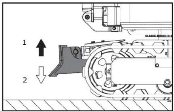
text_image
1 2natural_image
Technical line drawing of a mechanical assembly with no visible text or symbolstext_image
Technical diagram of a mechanical or electrical device with numbered components and directional arrows indicating flow or movement.natural_image
Technical line drawing of an excavator and tracked vehicle on a construction ground (no text or symbols)natural_image
Illustration of two excavators on a construction ground, showing different mechanical configurations (no text or symbols present)
natural_image
Line drawing of a bulldozer with a cross mark indicating failure or hazard, no text or symbols presentZWROTY

UWAGA!
natural_image
Technical diagram showing a mechanical assembly with an upward arrow and a side-view view of a vehicle wheel (no text or symbols present)natural_image
Diagram showing a device with two ports and a mechanical assembly with a rotating component (no text or symbols)text_image
Technical diagram showing a mechanical device with labeled components and directional arrows indicating assembly or operation.text_image
Technical diagram showing a device with labeled components and a schematic view of its internal structure with arrows indicating motion.text_image
Diagram showing a device with directional arrows and a mechanical assembly, labeled with components 1 and 2.text_image
Diagram showing airflow or movement of a device with labeled components and directional arrowsnatural_image
Line drawing of an excavator on a construction ground (no text or symbols)PARKOWANIE NA POCHYLENIU

natural_image
Technical line drawing of an excavator on a sloped terrain (no text or symbols)- Klin
WAŻNE INFORMACJE DOTYCZĄCE EKSPLOATACJI MASZYNY

UWAGA!
natural_image
Line drawing of an excavator on a flatbed truck, no text or symbols present
NIEBEZPIECZEŃSTWO!
natural_image
Illustration of a construction worker using a flatbed truck to lift or lift a slope, with arrows indicating upward forces (no text or symbols)text_image
250 to 300 mm 300 mm 250 to 300 mm 5000 mm 250 to 300 mmnatural_image
Line drawing of an excavator on a dump truck, no text or symbols presenttext_image
Technical diagram of a machine tool with numbered components and labeled partstext_image
Technical diagram of a mechanical assembly with numbered components and directional arrows indicating motion or movement.natural_image
Cartoon illustration of a truck with an excavator and a bucket, no text or symbols presentnatural_image
Technical line drawing of an excavator with labeled components (no text or symbols present)- Szekla
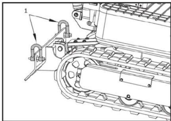
natural_image
Technical line drawing of a tracked vehicle with mechanical components and mounting brackets (no text or symbols)- Szekla
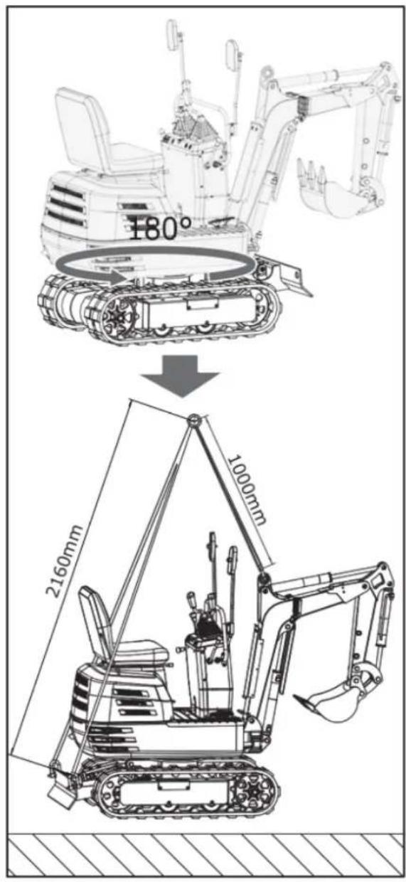
text_image
180° 2160mm 1000mmKONSERWACJA
ODSTĘPY MIĘDZY KONSERWACJĄ
text_image
Technical diagram of a tracked vehicle with numbered components and directional arrows indicating motion or movement.text_image
Technical diagram of a vehicle engine showing labeled components with numbered partsnatural_image
Technical line drawing of a vehicle engine bay with visible components and no text or symbols- Korek zbiornika
natural_image
Technical line drawing of a mechanical assembly with labeled component (no text or symbols present)- Odpowietrznik
natural_image
Technical line drawing of an electric motor assembly with labeled components (no text or symbols present)natural_image
Technical line drawing of a tank interior showing engine, chassis, and structural components (no text or labels)text_image
Technical diagram of a vehicle engine bay with numbered components and labeled partstext_image
Technical diagram of a tracked vehicle with labeled components and partstext_image
Technical diagram of an excavator with labeled parts including arm, bucket, and load componentsnatural_image
Technical line drawing of a mechanical assembly with labeled parts (no text or symbols present)natural_image
Technical line drawing of a mechanical assembly with no visible text or symbolsnatural_image
Technical line drawing of a bulldozer with visible tracks and components (no text or symbols)text_image
Technical diagram of a tracked vehicle showing engine, chassis, and drivetrain components with numbered labelsnatural_image
Technical line drawing of a mechanical component with internal parts and mounting holes (no text or symbols)text_image
Technical diagram of a vehicle engine bay with numbered components and labeled partsnatural_image
Technical line drawing of a mechanical assembly with gears and components (no text or symbols)natural_image
Technical line drawing of a tracked vehicle with visible tracks and components (no text or symbols)text_image
Technical diagram of a tracked vehicle with numbered components and directional arrows indicating assembly or inspection.natural_image
Silhouette of a human head with an optical device emitting sound waves, no text or symbols presentnatural_image
Line drawing of a hand using a tool to mark a bright spot on a grating tray (no text or symbols)
natural_image
Technical line drawing of a vehicle engine bay with internal components and no visible text or symbols- Świeca zapłonowa
natural_image
Technical line drawing of a tracked vehicle with visible tracks and components (no text or symbols)- Smarowniczka
CO 200 GODZIN SERWISOWYCH
text_image
Technical diagram of a tracked vehicle with numbered components and directional arrows indicating motion or assembly.1- Śruba mocująca
natural_image
Technical line drawing of a tracked robotic vehicle with visible engine and tracks (no text or symbols)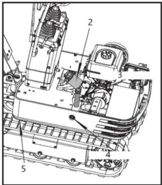
text_image
Technical diagram of a mechanical assembly with numbered components for identification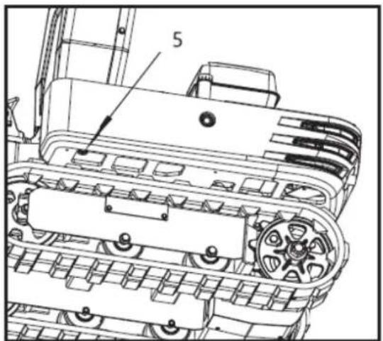
text_image
51- Filtr ssący
2- Filtr powrotny
INNE REGULACJE I WYMIANY
REGULACJA GASIENIC
text_image
Technical diagram of a tracked vehicle with numbered components and labeled parts1 śruba M20 × 120
2-nakrętka M20
3-30mm śliwka wench
natural_image
Technical line drawing of an excavator and tracked vehicle (no text or symbols)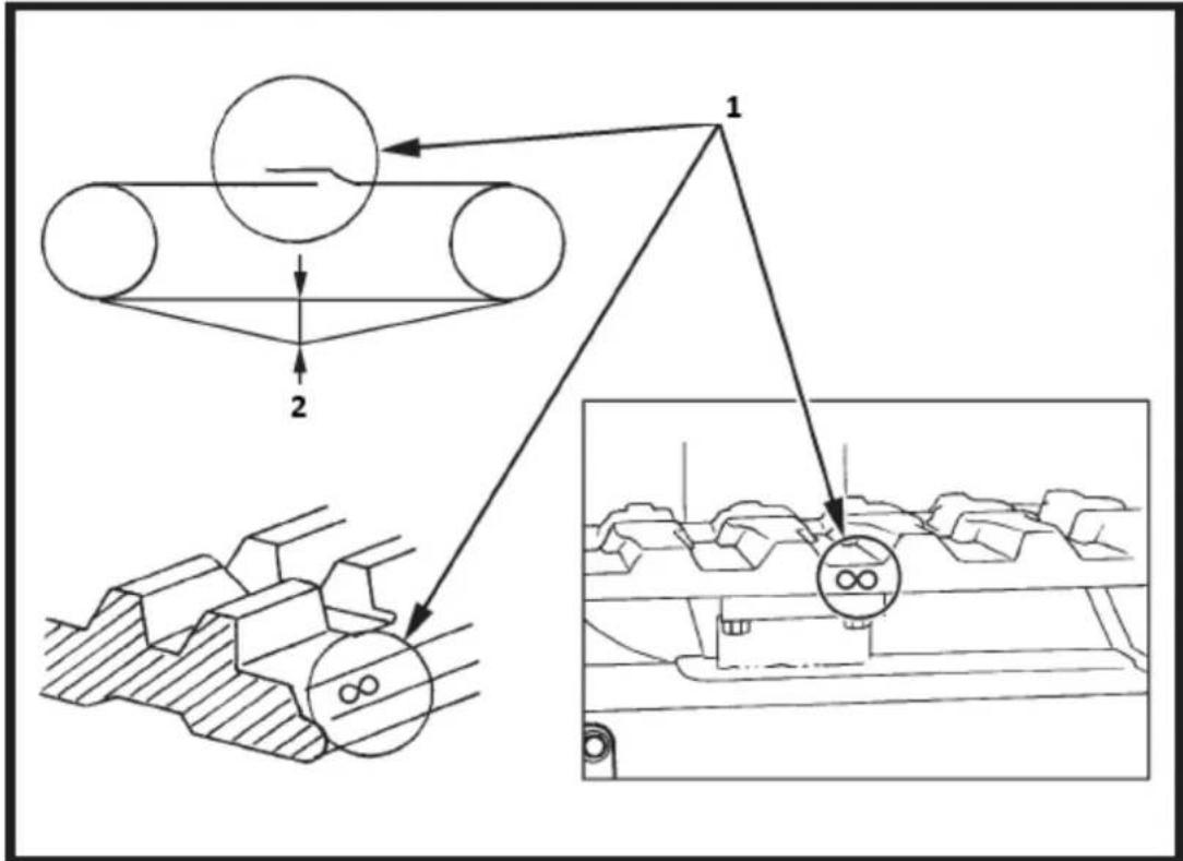
flowchart
graph TD
    A["Component 1"] --> B["Component 2"]
    B --> C["Output"]
    style A fill:#f9f,stroke:#333
    style B fill:#ccf,stroke:#333
    style C fill:#cfc,stroke:#333
text_image
Technical diagram of an automotive engine with labeled components and exploded viewtext_image
Technical diagram of a mechanical device with labeled components and exploded viewstext_image
Line No 12V Rated/Black Starting Motor Fremout Line. Line No. 12y Line No. 12y Gasoline Engine Starting Line, Line No. 65 Sterling Relay Line No. 17 Redblide Line No. 17 Redblide Replace ran with the large excavator cooling fan Line No. 3-1 Line No. 3-1 Line No. 3-1 Line No. 3-1 Line No. 3-1 Line No. 3-1 Line No. 3-1 Line No. 3-1 Line No. 3-1 Line No. 3-1 Line No. 3-1 Line No. 3-1 Line No. 3-1 Line No 3-1 Line No. 3-1 Line No. 3-1 Line No. 3-1 Line No. 3-1 Line No. 3-1 Line No. 3-1 Line No. 3-1 Line No. 3-1 Line No. 3-1 Line No. 3-1 Line No. 3-1 Line No. 3-2 Line No. 3-2 Line No. 3-2 Line No. 3-2 Line No. 3-2 Line No. 3-2 Line No. 3-2 Line No. 3-2 Line No. 3-2 Line No. 3-2 Line No. 3-2 Line No. 3-2 Line No. 3-2 Line No 3-2 Line No. 3-2 Line No. 3-2 Line No. 3-2 Line No. 3-2 Line No. 3-2 Line No. 3-2 Line No. 3-2 Line No. 3-2 Line No. 3-2 Line No. 3-2 Line No. 3-2 Line No. 3-1 Line No. 3-1 Line No. 3-1 Line No. 3-1 Line No. 3-1 Line No. 3-1 Line No. 3-1 Line No. 3-1 Line No. 3-1 Line No. 3-1 Line No. 3-1 Line No. 3-1 Line No. Line No. Line No. Line No. Line No. Line No. Line No. Line No. Line No. Line No. Line No. Line No. Line No. Line No. Line No. Line No. Line No. Line No. Line No. Line No. Line No. Line No. Line No. Line No. Line No. Line No. Line No. Line No. Line No. Line No. Line No. Line No. Line No. Line No. Side Power Source: Control unit (0 to -0) and Power Source: Control unit (0 to +0) and Power Source: Control unit (0 to +0) and Power Source: Control unit (0 to +0) and Power Source: Control unit (0 to +0) and Power Source: Control unit (0 to +0) and Power Source: Control unit (0 to +0) and Power Source: Control unit (0 to +0) and Power Source: Control unit (0 to +0) and Power Source: Control unit (0 to +0) and power source: Power Source: Control unit (0 to -0) and Power Source: Control unit (0 to +0) and Power Source: Control unit (0 to +0) and Power Source: Control unit (0 to +0) and Power Source: Control unit (0 to +0) and Power Source: Control unit (0 to +0) and Power Source: Control unit (0 to +0) and Power Source: Control unit (0 to +0) and Power Source: Control Unit (0 to +0) Power Source: Control unit (0 to -0) and Power Source: Control unit (0 to +0) and Power Source: Control unit (0 to +0) and Power Source: Control unit (0 to +0) and Power Source: Control unit (0 to +0) and Power Source: Control unit (0 to +0) and Power Source: Control Unit (0 to +0) Power Source: Control unit (0 to -0) and Power Source: Control unit (0 to +0) and Power source: Control unit (0 to +0) and Power source: Control unit (0 to +0) and Power source: Control unit (0 to +0) and Power source: Control unit (0 to +0) Power Source: Control unit (0 to -0) and Power Source: Control unit (0 to +0) and Power source: Control unit (0 to +0) and Power source: Control unit (0 to +0) and Power source: Control unit (0 to +0) Power Source: Control unit (0 to -0) and Power Source: Control unit (0 to +0) and Power source: Control unit (0 to +0) and Power source: Control unit (0 to +0) and Power source: Control unit (87) Power Source: Control unit (87) Power Source: Control unit (87) Power Source: Control unit (87) Power Source: Control unit (87) Power Source: Control unit (87) Power Source: Control unit (87) Power Source: Control unit (87) Power Source: Control unit (87) Power Source: Control unit (87) Power Source: Control unit (87) Power Source: Control unit (87) Power Source: Control Unit: Control Unit: Control Unit: Control Unit: Control Unit: Control Unit: Control Unit: Control Unit: Control Unit: Control Unit: Control Unit: Control Unit: Control Unit: Control Unit: Control Unit: Control Unit: Control Unit: Control Unit: Control Unit: Control Unit: Control Unit: Control Unit: Control Unit: Control Unit: Control Unit: Control Unit: Control Unit: Control Unit: Control Unit: Control Unit: Control Unit: Control Unit: Control Unit: Control Unit:text_image
Exploded view diagram of a mechanical assembly with numbered components for identification3.28. Lista części
text_image
Exploded view diagram of a mechanical assembly with numbered components and labeled partstext_image
Technical diagram of a tracked vehicle with numbered components and labeled partstext_image
Technical diagram of a mechanical assembly with numbered components for identificationnatural_image
Technical line drawing of a tracked excavator with levers and motors (no text or symbols)natural_image
Technical line drawing of a tracked excavator assembly with mounting bracket and guide rails (no text or symbols)natural_image
Line drawing of an excavator with tracked blade and bucket (no text or symbols)Instalacja grabi
natural_image
Technical line drawing of an excavator and tracked vehicle (no text or symbols)natural_image
Line drawing of an excavator with tracked base and mechanical components (no text or symbols)Instalacja kciuka
text_image
Technical diagram showing the assembly of an excavator with labeled components and motion arrows indicating changes.natural_image
Technical line drawing of an excavator with tracked components and control panel (no text or symbols)Montaż pazurów
natural_image
Technical line drawing of a tracked excavator with attached motors and levers (no text or symbols)natural_image
Line drawing of an excavator with tracked base and blade assembly (no text or symbols)natural_image
Technical line drawing of an excavator with tracked base and bucket, no text or symbols presentnatural_image
Line drawing of an excavator with tracked base and attached boom (no text or symbols)Montaż baldachimu
text_image
M10 x 95 x 3text_image
Diagram illustrating three scenarios of a vehicle's parking and anti-smoking behavior: no restrictions on the roof, no restrictions on the garage, and a vehicle moving to a car.text_image
Technical diagram of a mechanical engine with numbered components for identification1- Tłumik
2- ŚWIECA ZAPŁONOWA:
3- Dusić
text_image
Technical diagram of a mechanical engine with numbered components labeled 1, 2, and 3text_image
Technical diagram of a mechanical engine with numbered components for identification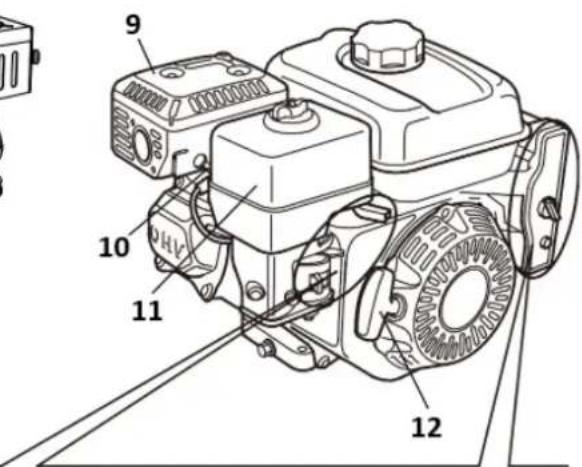
text_image
9 10 11 1213
13
text_image
Technical diagram of a mechanical assembly with numbered components labeled 1, 2, and 3
A
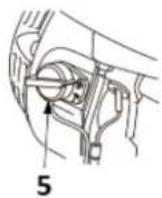
B
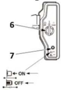
text_image
6 7 ON OFFtext_image
Technical diagram of a mechanical device with labeled components and directional arrows indicating motion or assembly.text_image
1 2 3 4 5 START CLOSED CHoke OPEN1- Otwarte
2- Dźwignia ssania
3- Zamknąć
4- Otwarte
5- Dźwignia ssania
natural_image
Illustration of a hand turning a mechanical component with a tool (no text or symbols)1- Uchwyt rozrusznika
4.3. SPRAWDŹ PRZED UŻYCIEM
CZY TWÓJ SILNIK JEST GOTOWY DO JAZDY?
text_image
CHECK RUN OFF ON 1 2 31- WYŁĄCZONY
2- ON
text_image
Technical diagram of a mechanical component with numbered parts and an arrow indicating motion or direction
text_image
Technical diagram of a device with labeled parts 2, 3, and internal components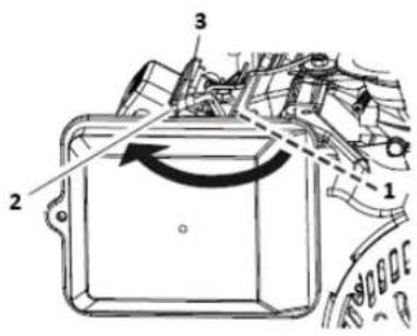
text_image
Technical diagram of a mechanical component with numbered parts and directional arrows indicating motion or flow.1- OTWARTE
2- ZAMKNAĆ
3- Dźwignia ssania
text_image
Technical diagram of a mechanical assembly with numbered components and directional arrows indicating motion or movement.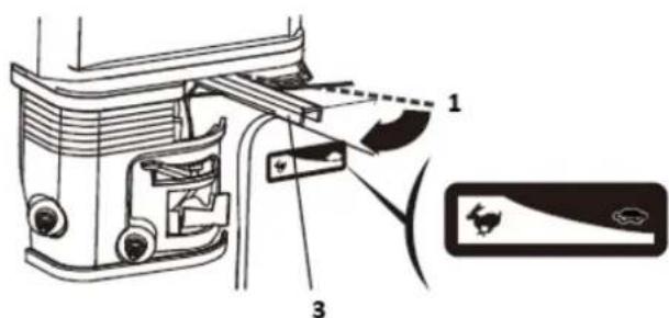
text_image
Technical diagram of a vehicle door assembly with labeled parts and component indicators1- Powolny
2- Szybko
text_image
Technical diagram showing mechanical component with labeled parts and rotation arrows, alongside a circular component with two numbered parts.1- ON
2- WYŁĄCZONY
natural_image
Diagram of a hand using a tool to adjust or install a circular component, labeled with number 1 (no text or symbols on the diagram itself)1-Rękojeść startowa
text_image
Technical diagram showing three mechanical assembly views with numbered components and directional arrows indicating motion or movement.1- Otwarte
2- Zamknąć
3- Dźwignia ssania
Zatrzymanie silnika
text_image
Technical diagram of a mechanical assembly with numbered components and directional arrows indicating motion or movement.1- Szybko
2- Powolny
text_image
1 2 O I 2 3 1text_image
Technical diagram of a mechanical device with numbered components and directional arrows indicating motion or rotation.text_image
Technical diagram showing mechanical assembly with numbered components and directional arrows indicating motion or flow.1- Szybko
2- Powolny
177F(E)/TR270(E)/TR306(E): 6,0 l
188F(E)/ TR389(E): 6,0 l
190F(E) /192F(E)/TR420(E)/TR440(E)/TR460(E): 6,0 l
text_image
Technical diagram showing a mechanical assembly with labeled components and a hand operating a valve or pump.text_image
Technical diagram showing mechanical assembly steps with numbered components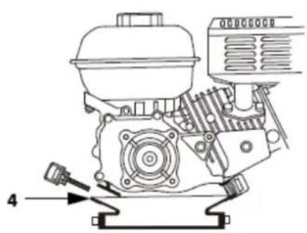
natural_image
Technical line drawing of a mechanical engine assembly (no text or symbols)text_image
Technical diagram of a mechanical component with labeled parts 3 and 41-Górny limit
2-Dolny limit
3-Korpus wlewu oleju/bagnet
4-Śruba spustowa
SERWISOWANIE SILNIKA
ZALECENIA DOTYCZĄCE OLEJU SILNIKOWEGO
text_image
Technical diagram showing exploded and assembled views of a mechanical device with labeled componentstext_image
Technical diagram of a mechanical assembly with numbered parts, likely illustrating a valve or actuator mechanism.natural_image
Line drawing of two hands holding a handheld device, one emitting a textured surface (no text or symbols)flowchart
graph LR
    A["1 Hand washing in a bowl"] --> B["2 Downing water droplets"]
    B --> C["3 Hand washing in a tray"]
    C --> D["4 Downing water droplets"]
1-Czyszczenie
text_image
Technical diagram of a mechanical assembly with numbered components for identification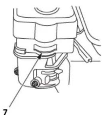
natural_image
Technical line drawing of a mechanical component with labeled parts (no text or symbols present)text_image
Diagram showing a mechanical device with labeled parts and an arrow indicating direction, likely illustrating a process or assembly.1-Czapka osadowa
F6RTC/F6TC:160F(E)/168F(E)/168FB(E)/TR163(E)/TR196(E)170F(E)/170FB(E)
/TR212(E)/TR223(E)/172F(E)/TR236(E)/177F(E)/TR270(E)/188F(E)/190F(E)/
190FB(E)/192F(E)/194F(E)/TR389(E)/TR420(E)/TR440(E)/TR460(E)/TR479(E)
natural_image
Technical line drawing of a vehicle engine showing intake and exhaust components (no text or labels)text_image
Exploded view diagram of a mechanical assembly with numbered parts for identification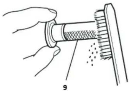
natural_image
Illustration of hands performing a mechanical assembly with a cylindrical component and textured surface (no text or symbols)1-Ostona tłumika
Śruby 2-5mm
3-Tłumik
Śruba 4-4mm
Nakrętki 5-8mm
text_image
Labeled diagram of a coffee maker with numbered parts for identificationtext_image
Technical diagram of a battery connected to an electrical motor, with labeled parts 1, 2, and 3.1- PRZEWÓD AKUMULATORA UJEMNY (-)
2- ELEKTROMAGNETYCZNY ROZRUSZNIKA
3- PRZEWÓD AKUMULATORA DODATNI(+)
text_image
Technical diagram of a mechanical assembly with numbered parts and exploded view, likely for assembly or maintenance instructions.text_image
Technical diagram of a mechanical assembly with numbered parts labeled 1 and 21- UCHWYT NA DRUTY
2- DŻWIGNIA SSANIA
177F(E)/TR270(E),188F(E)/190F(E)/TR389(E)/TR420(E)/TR440(E)/TR460(E)/TR479(E)
text_image
Technical diagram of a mechanical assembly with numbered parts, likely for repair or assembly instructions.text_image
Technical diagram of a mechanical assembly with numbered parts for identification1- ŚRUBA 4 mm
2- UCHWYT NA DRUTY
3- DRUT
4- PIERŚCIEN OSADCZY 5 mm
text_image
Diagram of a scientific apparatus with labeled components and a sensor or probe above ittext_image
Vertical sequence of icons representing various operational or safety symbols, including fuel, water, air, and communication.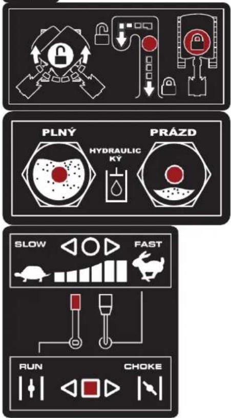
text_image
PLNY HYDRAULIC KY PRÁZD SLOW FAST RUN CHOKENamazat
Plyn
Hydraulický olej
natural_image
Three identical diagrams of robotic arms with numbered components, no text or symbols present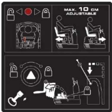
text_image
MAX. 10 CM ADJUSTABLE
natural_image
Illustration of a magnifying glass examining documents with tools, no text or symbols presentZásuvka 12V,15A
text_image
Diagram illustrating three scenarios of heavy machinery and a truck, with labeled icons and Chinese text.natural_image
Line drawing of an excavator on a utility pole with power lines and a lightning bolt symbol (no text or labels)natural_image
Technical line drawing of an excavator on a sloped terrain (no text or symbols)natural_image
Technical line drawing of an excavator with attached boom and suspension components (no text or symbols)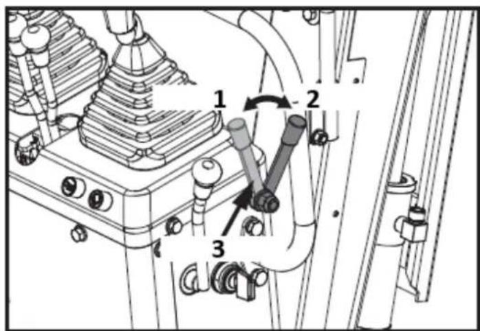
text_image
Technical diagram of a mechanical assembly with numbered components and directional arrows indicating motion or movement.1: Odemknout
2: Zámek
3: Páčka zámku
text_image
Technical diagram of a mechanical assembly with numbered components and directional arrows indicating motion or flow.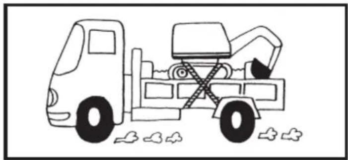
natural_image
Line drawing of a dump truck with an excavator and pile debris (no text or symbols)1-Odemknout
2-Zámek
natural_image
Diagram showing a hand holding a tool with a dashed line indicating motion or force (no text or symbols)natural_image
Silhouette of a human head with sunglasses and motion lines, symbolizing vision or perception (no text or symbols)text_image
Technical diagram of a vehicle rear panel with numbered components and directional arrows indicating parts of the body.1
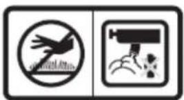
2

text_image
Two safety symbols: a hand crossed out with a prohibition sign and a person with a face detection icon.3

text_image
Collection of hazard warning symbols and pictograms, including physical hazards, safety, and human behavior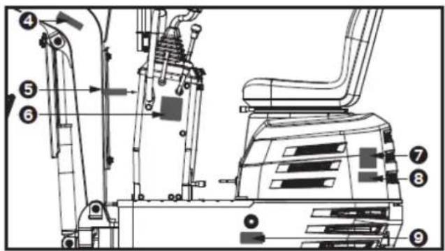
text_image
Technical diagram of an excavator with numbered components for identification and assembly reference.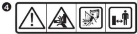
text_image
4
text_image
5 !6
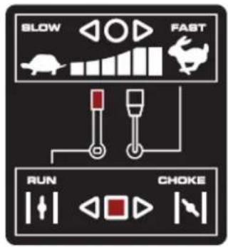
text_image
SLOW FAST RUN CHOKE7
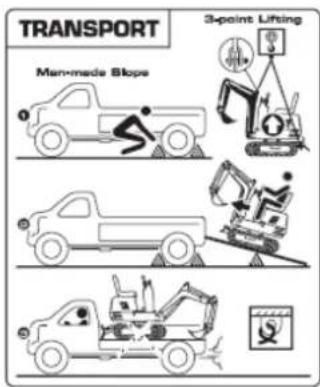
text_image
TRANSPORT Man-made Slope 3-point Lifting8
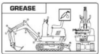
text_image
GREASE Platform Swing Control Panel9

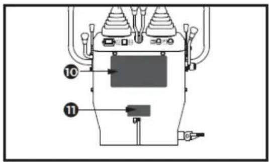
text_image
Technical diagram of a mechanical device with labeled components 10 and 11, showing internal structure and connections.10

flowchart
graph TD
    A["Robot Arm"] --> B["Control Unit"]
    C["Truck System"] --> D["Control Unit"]
    E["Drain System"] --> F["Control Unit"]
    G["Sensor System"] --> H["Control Unit"]
    I["Sensor System"] --> J["Control Unit"]
    K["Sensor System"] --> L["Control Unit"]
    M["Sensor System"] --> N["Control Unit"]
    O["Sensor System"] --> P["Control Unit"]
    Q["Sensor System"] --> R["Control Unit"]
    S["Sensor System"] --> T["Control Unit"]
    U["Sensor System"] --> V["Control Unit"]
    W["Sensor System"] --> X["Control Unit"]
    Y["Sensor System"] --> Z["Control Unit"]
11
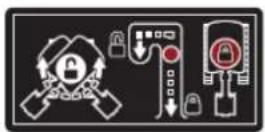
12
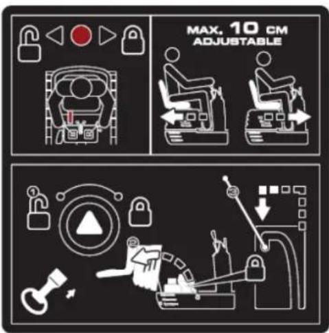
text_image
MAX, 10 CM ADJUSTABLE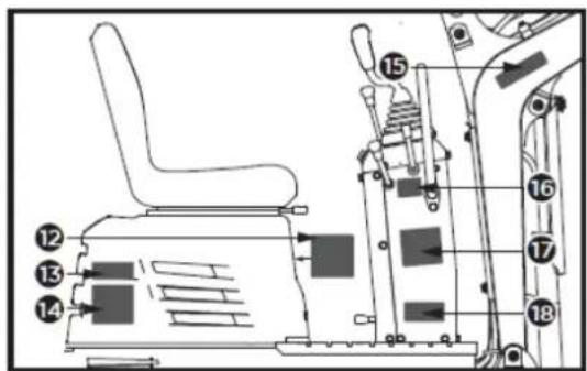
text_image
Technical diagram of an industrial vehicle's internal components with numbered parts labeled 12 to 1813
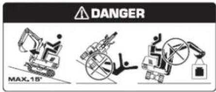
text_image
DANGER MAX.18°17
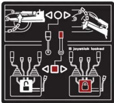
text_image
5 joystick looked14
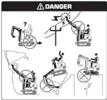
text_image
DANGER18
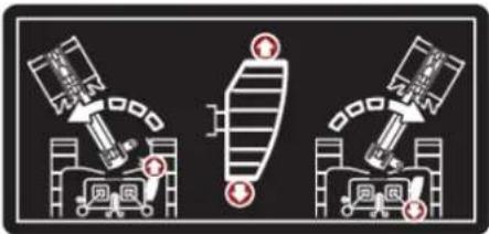
natural_image
Three diagrams showing robotic arm movements with no text or symbols15

text_image
Four warning symbols: triangular warning triangle with exclamation mark, triangular hazard symbol, lightning bolt symbol, and lightning bolt symbol.16
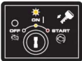
text_image
ON OFF STARTtext_image
Technical diagram of a mechanical device with labeled components and directional arrows indicating flow or movement.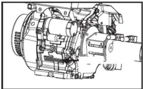
natural_image
Technical line drawing of a mechanical assembly with no visible text or symbols1- Model stroje č.
text_image
Technical diagram showing a mechanical assembly with tool coordinate axes and component layout, including a 1D view and a detailed exploded view.1- Šroub M12 (x1)
3.12. Dodaný obsah
text_image
Technical diagram of an excavator with labeled parts including base, levers, and clampstext_image
1 2 A 24mm 13mm 4mm1- Tenká matice M16 (x2)
text_image
Technical diagram of a mechanical device with labeled parts and a 16mm wrench icon1- Šroub M10x20 (x4)
text_image
X 2 13mm 1 C1- Šroub M8x30 (x4)
Sestava sedadla operátora
natural_image
Technical line drawing of a vehicle's internal components, showing a seat assembly and engine compartment (no text or symbols)text_image
Technical diagram of an excavator with numbered parts for identification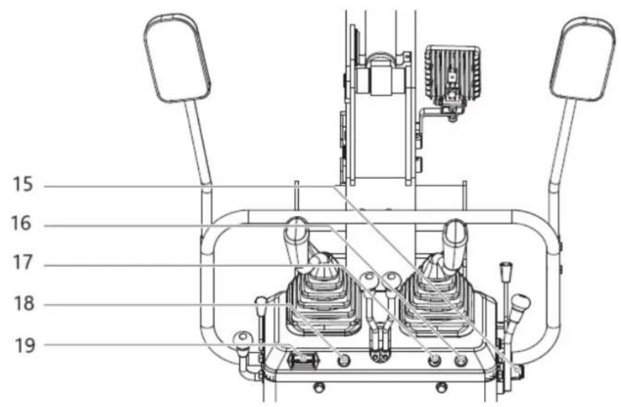
text_image
15 16 17 18 19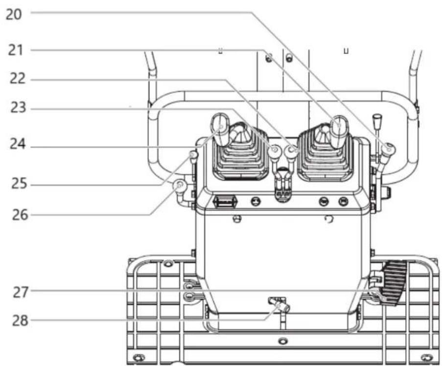
text_image
Technical diagram of a mechanical device with numbered components for identificationtext_image
Technical diagram of a mechanical assembly with numbered components and directional arrows indicating motion or movement.1- Odemknout
2- Zámek
3- Páčka zámku
text_image
Technical diagram showing mechanical assembly with numbered components and directional arrows indicating motion or movement.1- Odemknout
2- Zámek
natural_image
Technical line drawing of a mechanical device with no visible text or symbols1- Spínač klaksonu

DŮLEŽITÉ!
text_image
Technical diagram of a mechanical assembly with numbered components and directional arrows indicating motion or movement.1- ZAVŘENO
2- Palivový kohout
3- OTEVŘENO
text_image
Technical diagram of a mechanical or electrical component with numbered parts labeled 1 through 7.text_image
Technical diagram showing a mechanical control panel with labeled buttons and indicators, including symbols like '1', '2', and '3'.(1)- VYP
(2)- ZAPNUTO
(3)- START
natural_image
Technical line drawing of a mechanical device with no visible text or symbolsnatural_image
Technical line drawing of a mechanical device with no visible text or symbols1- Počítadlo hodin
text_image
Technical diagram of a mechanical assembly with numbered components and directional arrows indicating motion or flow.1- ZAVŘENO
2- Palivový kohout
3- OTEVŘENO

text_image
Technical diagram showing the installation of an excavator with labeled components and a downward arrow indicating process flow.Záběh nového stroje
text_image
Technical diagram of a mechanical assembly with numbered components and directional arrows indicating motion or movement.1- Odemknout
2- Zámek
3- Páčka zámku
natural_image
Technical line drawing of a mechanical assembly with no visible text or symbolstext_image
Technical diagram of an excavator with labeled parts and directional arrows indicating motion or assembly.POZNÁMKA: Viz „OTOČNÝ POHYB A POHYB KYVU“.
natural_image
Technical diagram of a mechanical piping system with valve and valve components (no text or labels)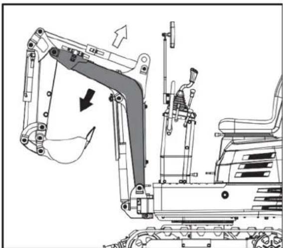
natural_image
Technical line drawing of an excavator assembly with no visible text or symbols
natural_image
Technical diagram of a mechanical system with pipes and housing, showing directional arrows (no text or labels)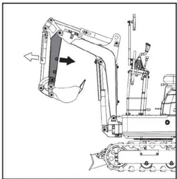
natural_image
Technical line drawing of an excavator and tracked vehicle (no text or symbols)OBSLUHA Kbelíku
natural_image
Technical diagram of a piping system with valves and a valve mechanism (no text or labels)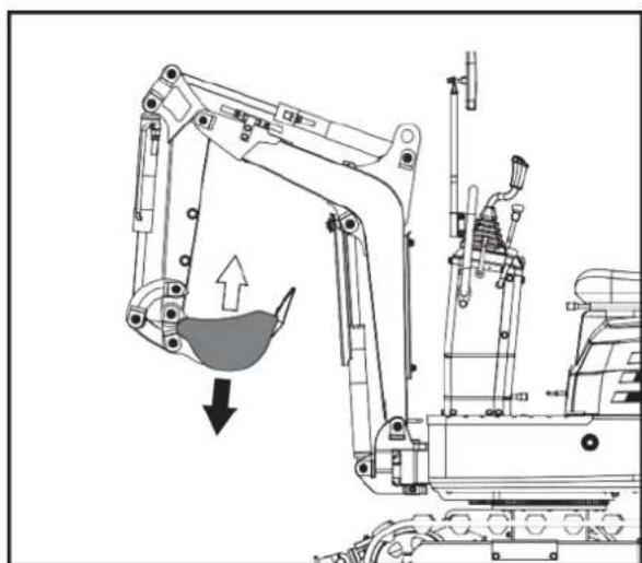
natural_image
Technical line drawing of an excavator with load and component assembly (no text or symbols)OVLÁDÁNÍ OTÁČENÍ (JEDNOTKY).

UPOZORNĚNÍ!
natural_image
Technical diagram of a mechanical or industrial system with pipes and valves, no visible text or symbols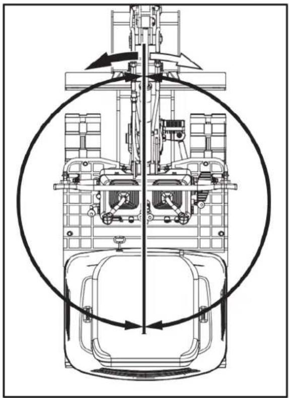
natural_image
Technical line drawing of a mechanical assembly with no visible text or symbolsOBSLUHA BOOM SWING
text_image
Technical diagram of a mechanical assembly with labeled components A and B, showing internal components and directional arrows.natural_image
Technical line drawing of a mechanical assembly with no visible text or symbols- Opravit
OBSLUHA DOZERU
text_image
Technical diagram of a mechanical assembly with labeled parts A, B, and directional arrows indicating movement or force.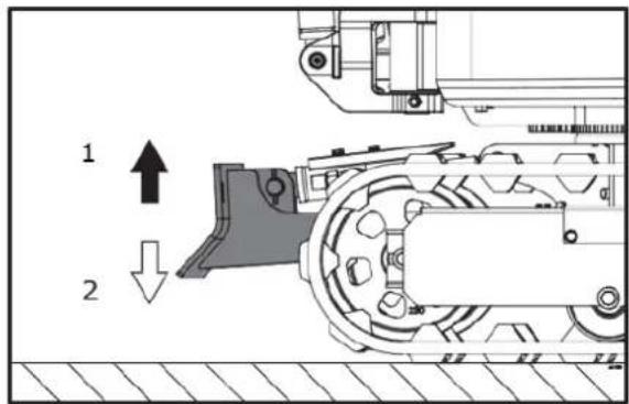
text_image
1 21.Zvedněte.2.Spodní
natural_image
Technical line drawing of a mechanical assembly with no visible text or symbolsnatural_image
Technical line drawing of an excavator with a 20-40cm height dimension标注 (no other text or symbols)text_image
Technical diagram of a mechanical or electrical device with numbered components and directional arrows indicating flow or movement.natural_image
Technical line drawing of an excavator with labeled component '1' and directional arrow (no text or symbols beyond labels)natural_image
Two excavators in action poses with arrows indicating motion direction (no text or symbols)
natural_image
Line drawing of a bulldozer with a cross mark indicating failure, no text or symbols presentOTOČENÍ

UPOZORNĚNÍ!
natural_image
Technical diagram showing a mechanical assembly with an upward arrow and a side-view view of a vehicle wheel (no text or symbols present)text_image
Technical diagram showing a device with internal components and a mechanical assembly with directional arrows indicating motion or transformation.text_image
Technical diagram showing a device with labeled components and a mechanical assembly with directional arrows.text_image
Technical diagram showing a device with labeled components and a schematic view of its internal structure.text_image
Diagram illustrating a mechanical device with directional arrows and labeled components, including a zoomed-in view of the internal structure.text_image
Diagram showing a device with lightbulb and directional arrows, alongside its internal structure with labeled components 1 and 2.natural_image
Line drawing of an excavator on a construction ground (no text or symbols)PARKOVÁNÍ NA SVAHU

natural_image
Technical line drawing of an excavator on a sloped terrain (no text or symbols)- Klín
DŮLEŽITÉ INFORMACE O PROVOZU STROJE

UPOZORNĚNÍ!
natural_image
Line drawing of an excavator on a flatbed truck (no text or symbols)
NEBEZPEČÍ OHROŽENÍ ŽIVOTA!
natural_image
Illustration of a construction worker using a flatbed truck to lift or lift material, with arrows indicating upward forces (no text or symbols)text_image
250 to 300 mm 300 mm 250 to 300 mm 5000 mm 250 to 300 mmnatural_image
Line drawing of an excavator on a flatbed truck, no text or symbols presenttext_image
Technical diagram of a machine tool with numbered components and labeled partstext_image
Technical diagram of a mechanical assembly with numbered components and directional arrows indicating motion or movement.natural_image
Cartoon illustration of a truck dumping material into a flatbed trailer with a bucket (no text or symbols)natural_image
Technical line drawing of an excavator with labeled components (no text or symbols present)- Okov
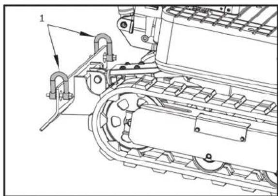
natural_image
Technical line drawing of a mechanical assembly with rollers and guide rails (no text or symbols)- Okov
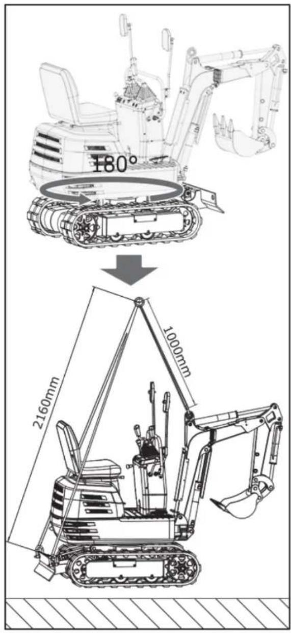
text_image
180° 2160mm 1000mmÚDRŽBA
INTERVALY ÚDRŽBY
text_image
Technical diagram of a tracked vehicle with numbered components and directional arrows indicating motion or movement.text_image
Technical diagram of a vehicle engine showing labeled components with numbered partsnatural_image
Technical line drawing of a vehicle engine bay with visible components and no text or symbols- Víčko nádrže
natural_image
Technical line drawing of a mechanical assembly with labeled component (no text or symbols present)- Dýchač vzduchu
natural_image
Technical line drawing of an electric motor assembly with labeled components (no text or symbols present)natural_image
Technical line drawing of a tank interior showing engine, chassis, and structural components (no text or labels)text_image
Technical diagram of a vehicle engine bay with numbered components and labeled partstext_image
Technical diagram of a tracked vehicle with labeled components and partstext_image
Technical diagram of an excavator with labeled parts including arm, bucket, and load componentsnatural_image
Technical line drawing of a mechanical assembly with labeled parts (no text or symbols present)natural_image
Technical line drawing of a mechanical assembly with no visible text or symbolsnatural_image
Technical line drawing of a bulldozer with visible tracks and components (no text or symbols)- čep spojky lopaty (x5)
text_image
Technical diagram of a tracked vehicle engine showing labeled components including engine, motors, and chassis parts.natural_image
Technical line drawing of a mechanical component with internal parts and mounting holes (no text or symbols)text_image
Technical diagram of a vehicle engine bay with numbered components and labeled partsnatural_image
Technical line drawing of a mechanical assembly with no visible text or symbolsnatural_image
Technical line drawing of a tracked vehicle with mechanical components and no visible text or symbolstext_image
Technical diagram of a tracked vehicle with numbered components and directional arrows indicating assembly or movement.natural_image
Silhouette of a human head with an optical device emitting arrows, no text or symbols presentnatural_image
Line drawing of a hand using a tool to mark a bright spot on a rectangular grating (no text or symbols)
natural_image
Technical line drawing of a vehicle engine bay with internal components and no visible text or symbolsnatural_image
Technical line drawing of a tracked vehicle with visible tracks and components (no text or symbols)- Maznice
KAŽDÝCH 200 SERVISNÍCH HODIN
text_image
Technical diagram of a tracked vehicle with numbered components and directional arrows indicating motion or assembly.1- Upevňovací šroub
natural_image
Technical line drawing of a tracked robotic vehicle with visible engine and tracks (no text or symbols)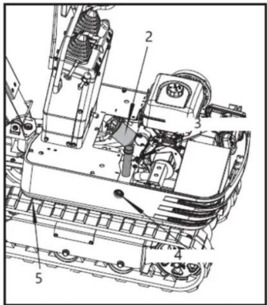
text_image
Technical diagram of a mechanical assembly with numbered components labeled 1 to 5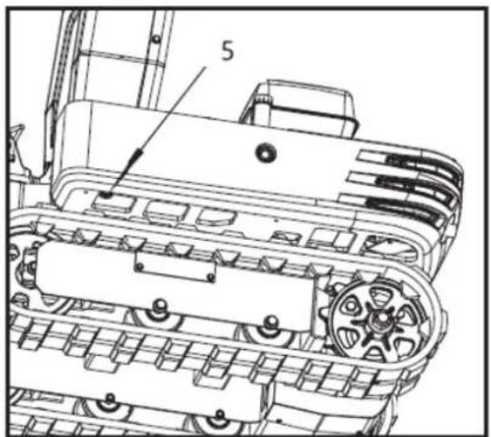
text_image
51- Sací filtr
2- Zpětný filtr
text_image
Technical diagram of a tracked vehicle with numbered components and labeled parts1-šroub M20 × 120
2-matice M20
3-30mm švestka
natural_image
Technical line drawing of an excavator with tracked base and support structure (no text or symbols)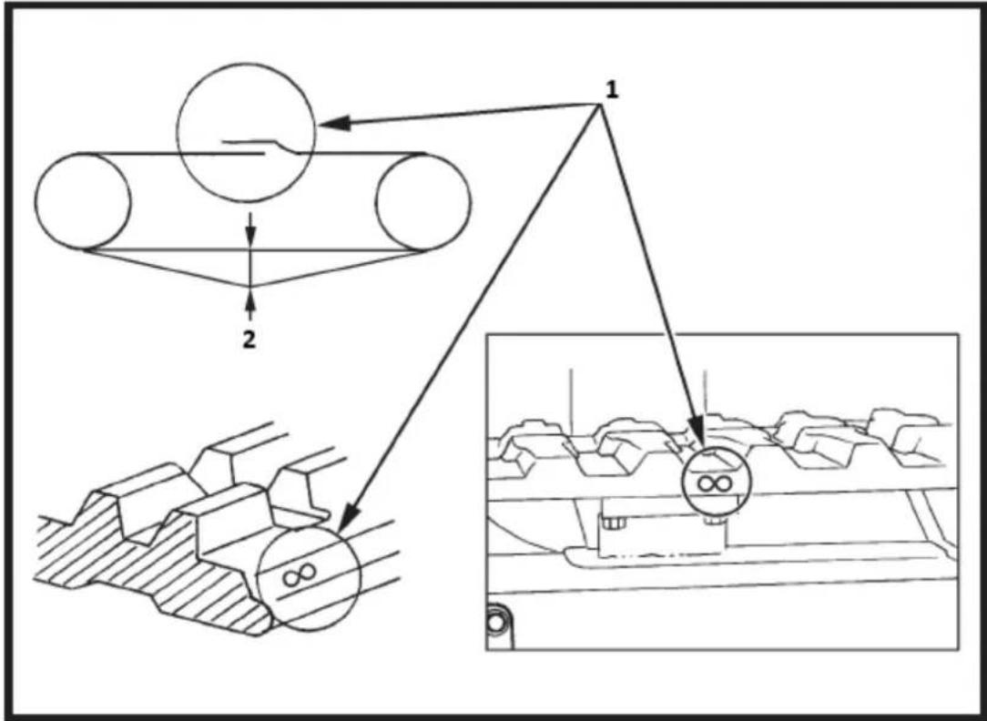
flowchart
graph TD
    A["Component 1"] --> B["Component 2"]
    B --> C["Output"]
    style A fill:#f9f,stroke:#333
    style B fill:#ccf,stroke:#333
    style C fill:#cfc,stroke:#333
text_image
Technical diagram of an automotive engine with labeled components and exploded viewtext_image
Technical diagram of a mechanical device with labeled parts and exploded viewstext_image
Line No 12V Rated/Black Starting Motor Fermostat Line. Line No. 12y Line No. 12y Sterling Relay Gasoline Engine Starting Line, Line No. 65 Line No. 12y Line No. 17 Redblide Line No. 17 Redblide Replace ran with the large excavator cooling fan Line No. 3-1 Line No. 3-1 Line No. 3-1 Line No. 3-1 Line No. 3-1 Line No. 3-1 Line No. 3-1 Line No. 3-1 Line No. 3-1 Line No. 3-1 Line No. 3-1 Line No. 3-1 Line No. 3-1 Line No 3-1 Line No. 3-1 Line No. 3-1 Line No. 3-1 Line No. 3-1 Line No. 3-1 Line No. 3-1 Line No. 3-1 Line No. 3-1 Line No. 3-1 Line No. 3-1 Line No. 3-1 Line No. 3-2 Line No. 3-2 Line No. 3-2 Line No. 3-2 Line No. 3-2 Line No. 3-2 Line No. 3-2 Line No. 3-2 Line No. 3-2 Line No. 3-2 Line No. 3-2 Line No. 3-2 Line No. 3-2 Line No 3-2 Line No. 3-2 Line No. 3-2 Line No. 3-2 Line No. 3-2 Line No. 3-2 Line No. 3-2 Line No. 3-2 Line No. 3-2 Line No. 3-2 Line No. 3-2 Line No. 3-2 Line No. 3-1 Line No. 3-1 Line No. 3-1 Line No. 3-1 Line No. 3-1 Line No. 3-1 Line No. 3-1 Line No. 3-1 Line No. 3-1 Line No. 3-1 Line No. 3-1 Line No. 3-1 Line No. Line No. Line No. Line No. Line No. Line No. Line No. Line No. Line No. Line No. Line No. Line No. Line No. Line No. Line No. Line No. Line No. Line No. Line No. Line No. Line No. Line No. Line No. Line No. Line No. Line No. Line No. Line No. Line No. Line No. Line No. Line No. Line No. Line No. Side Power Source: Control unit (0 to -0) and power output (in Vdc) Power Source: Control unit (0 to -0) and power output (in Vdc) Power Source: Control unit (0 to -0) and power output (in Vdc) Power Source: Control unit (0 to -0) and power output (in Vdc) Power Source: Control unit (0 to -0) and power output (in Vdc) Power Source: Control unit (0 to -0) and power output (in Vdc) Power Source: Control unit(0 to -0) and power output(0 to -0) and power output(0 to -0) Power Source: Control unit(0 to -0) and power output(0 to -0) and power output(0 to -0) Power Source: Control unit(0 to -0) and power output(0 to -0) and power output(0 to -0) Power Source: Control unit(0 to -0) and power output(0 to -0) and power output(0 to -0) Power Source: Control unit(0 to -0)and power output(0 to -0) and power output(0 to -0) Power Source: Control unit(0 to -0) and power output(0 to -0) and power output(0 to -0) Power Source: Control unit(0 to -0) and power output(0 to -0) and power output(0 to -0) Power Source: Control unit(0 to -0) and power output(0 to -0) and power output(text_image
Exploded view diagram of a mechanical assembly with numbered components for identification3.28. Seznam dílů
text_image
Exploded view diagram of a mechanical assembly with numbered parts for identificationtext_image
Technical diagram of a tracked vehicle with numbered components and exploded view, likely for assembly or maintenance purposes.text_image
Technical diagram of a mechanical assembly with numbered components for identificationnatural_image
Technical line drawing of a tracked excavator with levers and motors (no text or symbols)text_image
M10 x 40 x 2natural_image
Line drawing of an excavator with tracked blade and bucket (no text or symbols)Instalace hrábě
natural_image
Technical line drawing of an excavator and tracked vehicle (no text or symbols)natural_image
Line drawing of an excavator with tracked base and mechanical components (no text or symbols)Instalace palce
text_image
Technical diagram showing the assembly of an excavator with labeled components and motion arrows indicating changes.natural_image
Technical line drawing of an excavator with tracked components and control panel (no text or symbols)Instalace drápů
natural_image
Technical line drawing of a tracked excavator with attached mechanical components (no text or symbols)natural_image
Line drawing of an excavator with tracked base and blade assembly (no text or symbols)natural_image
Technical line drawing of an excavator with tracked base and bucket, no text or symbols presentnatural_image
Line drawing of an excavator with tracked base and attached boom (no text or symbols)text_image
M10 x 95 x 3text_image
Diagram illustrating three scenarios of a vehicle's parking and anti-smoking behavior: no restrictions on the roof, no restrictions on the garage, and a vehicle moving to a car.text_image
Technical diagram of a mechanical engine with numbered components for identification1- Tlumič
2- ZAPALOVACÍ SVÍČKA:
3- Sytič
4- Kryt hlavy válce
5- VZDUCHOVÝ FILTR:
6- Zpětný startér
7- Rukojeť startéru
text_image
Technical diagram of a mechanical engine with numbered components labeled 1, 2, and 31- Palivová nádrž
text_image
Technical diagram of a mechanical engine with numbered components for identification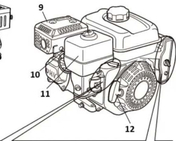
text_image
9 10 11 1213
13
text_image
Technical diagram of a mechanical assembly with numbered parts labeled 1, 2, and 3
A

B
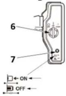
text_image
6 7 ON OFFtext_image
Technical diagram of a mechanical assembly with labeled components and directional arrows indicating motion or movement.1- Pomalý
2- Rychle
3- Páčka klapky
Spínač motoru
text_image
1 2 3 4 5 START CLOSED CHoke OPEN1- OTEVŘENO
2- Páčka sytiče
3- Blízko
4- OTEVŘENO
5- Páčka sytiče
natural_image
Illustration of a hand turning a mechanical component with a tool (no text or symbols)1- Rukojeť startéru
4.3. PŘED PROVOZEM ZKONTROLUJTE
JE VÁŠ MOTOR PŘIPRAVEN K PROVOZU?
text_image
Technical diagram of a mechanical component with numbered parts and directional arrows indicating flow or movement.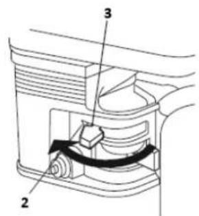
text_image
Technical diagram of a mechanical device with labeled parts 2, 3, and a scroll-like component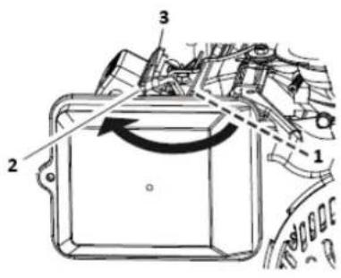
text_image
Technical diagram of a mechanical component with numbered parts and directional arrows indicating motion or flow.text_image
Technical diagram of a mechanical assembly with numbered components and directional arrows indicating motion or movement.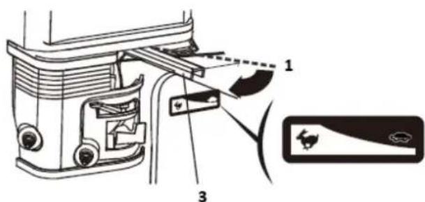
text_image
Technical diagram of a vehicle door assembly with labeled parts and component indicators1- Pomalý
2- Rychle
3- Páčka klapky
text_image
Technical diagram showing mechanical component with labeled parts and rotation arrows, alongside a circular component with two numbered parts.1- NA
2- VYPNUTO
3- Spínač motoru
- Spustte startér.
natural_image
Diagram of a hand turning a mechanical component with labeled parts (no text or symbols present)text_image
Technical diagram of a mechanical assembly with numbered components and labeled parts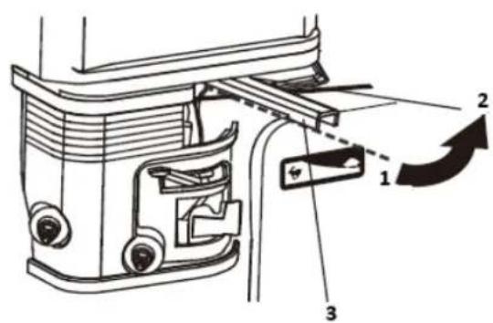
text_image
Technical diagram of a mechanical assembly with numbered components and directional arrows indicating motion or assembly.1- Rychle
2- Pomalý
3- Páčka klapky
text_image
1 2 O I 2 3 11- NA
2- VYPNUTO
3- Spínač motoru
text_image
Technical diagram of a mechanical device with numbered components and directional arrows indicating motion or rotation.1- OTEVŘENO
2- Blízko
text_image
Technical diagram showing mechanical assembly with numbered components and directional arrows indicating motion or flow.1- Rychle
2- Pomalý
3- Páčka klapky
4.5. ÚDRŽBA
Důležitost údržby
text_image
Technical diagram showing a mechanical assembly with labeled components and a hand holding a tool, likely illustrating a testing or installation procedure.text_image
Technical diagram showing mechanical assembly with labeled parts, including a drain component and three numbered parts.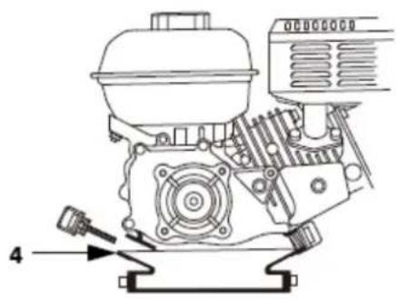
natural_image
Technical line drawing of a mechanical engine assembly (no text or symbols)text_image
Technical diagram showing exploded and assembled views of a mechanical device with labeled componentstext_image
Technical diagram of a mechanical assembly with numbered parts, likely for assembly or maintenance instructions.1-křídlá matice
natural_image
Line drawing of two hands holding a handheld device, one emitting a device from a grid-patterned device (no text or symbols)flowchart
graph LR
    A["1 Hand washing in a bowl"] --> B["2 Downing liquid"]
    B --> C["3 Hand washing in a tray"]
    C --> D["4 Downing liquid"]
1-Vyčistit
text_image
Technical diagram of a mechanical assembly with numbered parts for identification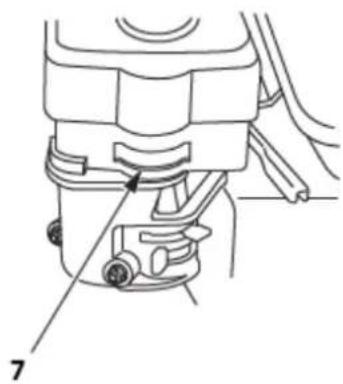
natural_image
Technical line drawing of a mechanical component with labeled parts (no text or symbols present)text_image
Diagram showing a mechanical device with labeled parts, including a piston and valve assembly.F6RTC/F6TC:160F(E)/168F(E)/168FB(E)/TR163(E)/TR196(E)170F(E)/170FB(E)
/TR212(E)/TR223(E)/172F(E)/TR236(E)/177F(E)/TR270(E)/188F(E)/190F(E)/190FB(E)/192F(E)/194F(E)/TR389(E)/TR420(E)/TR440(E)/TR460(E)/TR479(E)
Nebo jiné ekvivalenty.
| F6RTC | F7RTC | |
| MISTR | RN6YC/RN6Y | RN7YC/RN7Y |
| NGK | BPR6ES | BPR7ES |
| DENSO | W20EPR_U | W22EPR_U |
| BOSCH | WR7DC | WR5DC |

natural_image
Technical line drawing of a vehicle engine showing intake and exhaust components (no text or labels)text_image
Exploded view diagram of a mechanical assembly with numbered parts for identification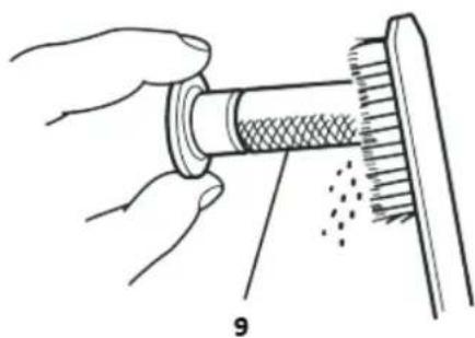
natural_image
Illustration of hands performing a mechanical tool with a meshed component and dotted lines indicating motion (no text or symbols)1-Protektor tlumiče
šrouby 2-5 mm
3-tlumič výfuku
šroub 4-4mm
matice 5-8 mm
text_image
Technical diagram of a coffee maker with labeled parts including feeding machine, funnel, and pumptext_image
Technical diagram of a battery connected to an automotive engine, with labeled parts 1, 2, and 3.1- NEGATIVNÍ (-) KABEL BATERIE
2- SOLENOID STARTÉRU
3- POZITIVNÍ (+) KABEL BATERIE
text_image
Technical diagram of a mechanical assembly with numbered parts and exploded view, likely for assembly or maintenance instructions.1- TŘECÍ MATICE PÁKY PLYNU
2- ZPĚTNÉ JARO
3- FLEXIBILNÍ MONTÁŽ DRÁTOVÉHO JÁDRA
4- MONTÁŽ PEVNÉHO DRÁTĚNÉHO JÁDRA
5- DRÁT
6- 5 mm KRUHOVÝ KRUH
7- ŠROUB 4 mm
8- DRŽÁK DRÁTU
9- PÁKA PLYNU
10- VOLITELNÝ
PROPOJENÍ DÁLKOVÉHO SYTIČE
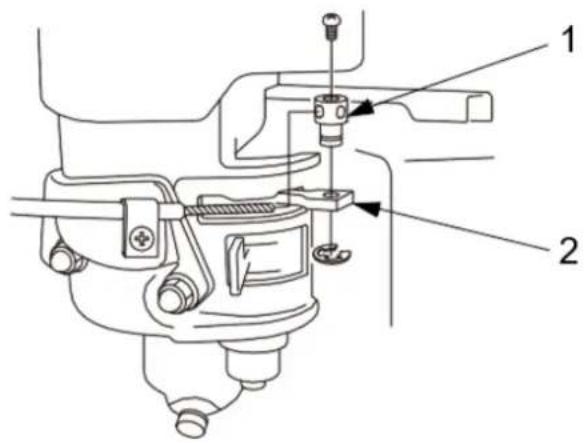
text_image
Technical diagram of a mechanical assembly with labeled parts 1 and 21- DRŽÁK DRÁTU
2- PÁKA SYTIČE
177F(E)/TR270(E),188F(E)/190F(E)/TR389(E)/TR420(E)/TR440(E)/TR460(E)/TR479(E)
VZDÁLENÉ OVLÁDÁNÍ PLYNU
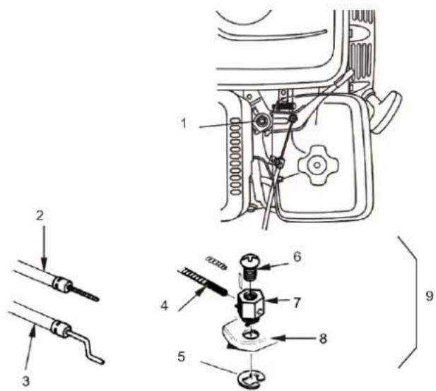
text_image
Technical diagram of a mechanical assembly with numbered parts and labeled parts for identification.1- TŘECÍ MATICE PÁKY PLYNU
2- FLEXIBILNÍ MONTÁŽ DRÁTOVÉHO JÁDRA
3- MONTÁŽ PEVNÉHO DRÁTĚNÉHO JÁDRA
4- DRÁT
5- 5 mm OKRUH
6- ŠROUB 4 MM
7- DRŽÁK DRÁTU
8- PÁKA PLYNU
9- VOLITELNÝ
PROPOJENÍ DÁLKOVÉHO SYTIČE
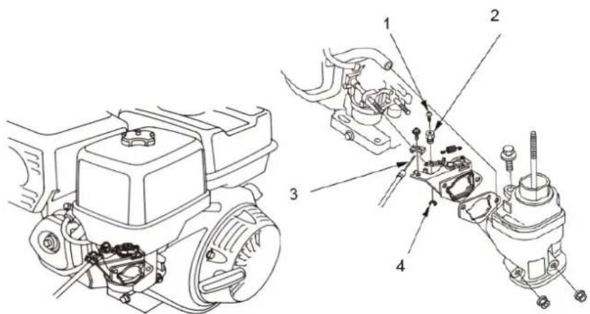
text_image
Technical diagram showing mechanical assembly with numbered components for maintenance or repair1- ŠROUB 4 mm
2- DRŽÁK DRÁTU
3- DRÁT
4- 5 mm KRUHOVÝ KRUH
| IG | E | BAT | ST | |
| OFF | o—o | |||
| ON | ||||
| START | o—o |
text_image
Diagram of a scientific apparatus with labeled components and a sensor or probe above itnatural_image
Diagram of two robotic arms with labeled joints, no text or symbols presentnatural_image
Illustration of a magnifying glass examining a document with icons, no text presentTube manuel
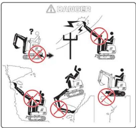
text_image
DANGERtext_image
Diagram illustrating three scenarios of heavy machinery collision and maintenance, showing workers moving on a truck, using excavators, and using a hook device.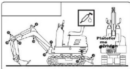
text_image
Platefor me givbghv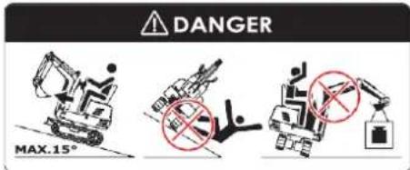
text_image
DANGER MAX.15°natural_image
Line drawing of an excavator on a utility pole with power lines and a warning sign (no text or symbols)natural_image
Technical line drawing of an excavator on a sloped terrain (no text or symbols)natural_image
Technical line drawing of an excavator with attached platform and base mount (no text or symbols)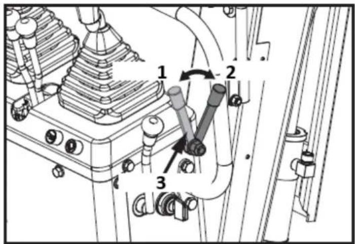
text_image
Technical diagram of a mechanical assembly with numbered components and directional arrows indicating motion or movement.1 : Déverrouiller
2 : Verrouillage
text_image
Technical diagram of a mechanical assembly with numbered components and directional arrows indicating motion or flow.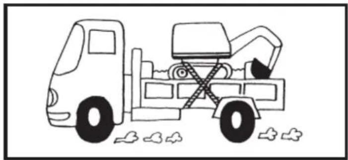
natural_image
Line drawing of a dump truck with an excavator and pile debris (no text or symbols)natural_image
Diagram of a mechanical joint or fracture with dashed lines indicating direction (no text or symbols)natural_image
Silhouette of a human head with sunglasses and motion lines, symbolizing vision or perception (no text or symbols)text_image
Technical diagram of a device rear panel with labeled components and directional arrows1

text_image
Two safety symbols: a bird silhouettes without a warning sign and a shielded object with explosive hazard.2


text_image
Collection of hazard warning symbols and pictograms, including physical contact, safety, and emergency signs
text_image
Technical diagram of an excavator with numbered components for identification and assembly reference.
text_image
4 !
text_image
5 !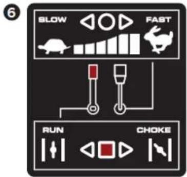
text_image
6 BLOW FAST RUN CHOKE
text_image
7 TRANSPORT Man-made Slope 3-point Lifting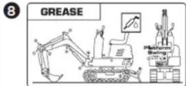
text_image
8 GREASE Platform Swing -0.777 cm
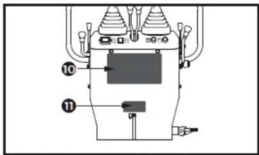
text_image
Technical diagram of a mechanical device with labeled components 10 and 11, showing internal structure and connections.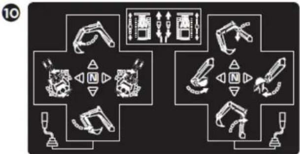
flowchart
graph TD
    A["Robot Arm"] --> B["Tool Icon"]
    B --> C["Control Panel"]
    C --> D["Robot Arm"]
    D --> E["Tool Icon"]
    E --> F["Control Panel"]
    F --> G["Robot Arm"]
    G --> H["Tool Icon"]
    H --> I["Control Panel"]
    I --> J["Robot Arm"]
    J --> K["Tool Icon"]
    K --> L["Control Panel"]
    L --> M["Robot Arm"]
    M --> N["Tool Icon"]
    N --> O["Control Panel"]
    O --> P["Robot Arm"]
    P --> Q["Tool Icon"]
    Q --> R["Control Panel"]
    R --> S["Robot Arm"]
    S --> T["Tool Icon"]
    T --> U["Control Panel"]
11
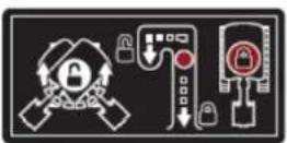
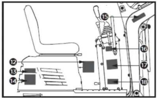
text_image
Technical diagram of an industrial machine with numbered components for identification12

text_image
MAX. 10 CM ADJUSTABLE13
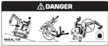
text_image
DANGER MAX.15°14
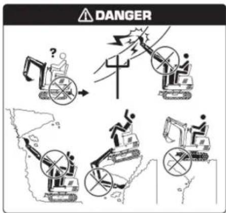
text_image
DANGER17
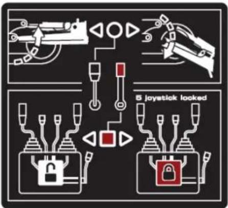
text_image
5 joystick looked18
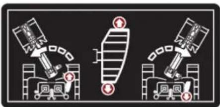
natural_image
Three diagrams showing mechanical assembly or lifting process with no visible text or symbols15

text_image
Four warning symbols: warning triangle with exclamation mark, triangular warning triangle with broken line, broken line with falling object, and broken line with falling object.16
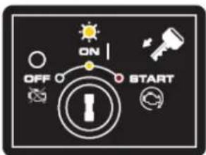
text_image
ON OFF STARTtext_image
Technical diagram of a mechanical device with labeled components and directional arrows indicating flow or movement.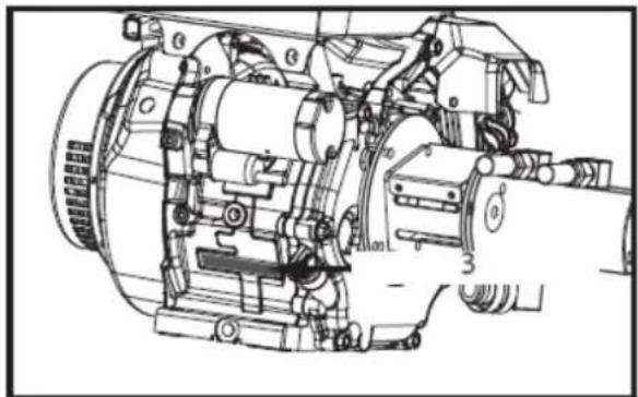
natural_image
Technical line drawing of a mechanical assembly with no visible text or symbolstext_image
Technical diagram showing a mechanical assembly with tool coordinate axes and component layout, including a 1D view and a 2D view.1- Boulon M12 (x1)
3.12. Contenu fourni
text_image
Technical diagram of an excavator with labeled parts including base, levers, and clampstext_image
1 2 A 24mm 13mm 4mmtext_image
Technical diagram of a mechanical device with labeled parts and a 16mm wrench icon1- Boulon M10x20 (x4)
text_image
X 2 13mm 1 C1- Boulon M8x30 (x4)
natural_image
Technical line drawing of a vehicle's internal components, showing a seat assembly and engine compartment (no text or symbols)text_image
Technical diagram of an excavator with numbered parts for identification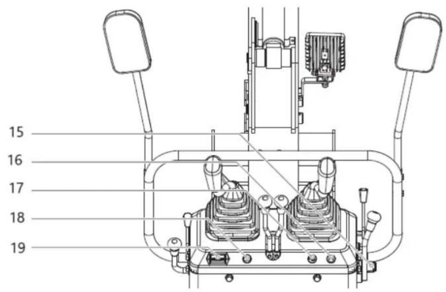
text_image
15 16 17 18 19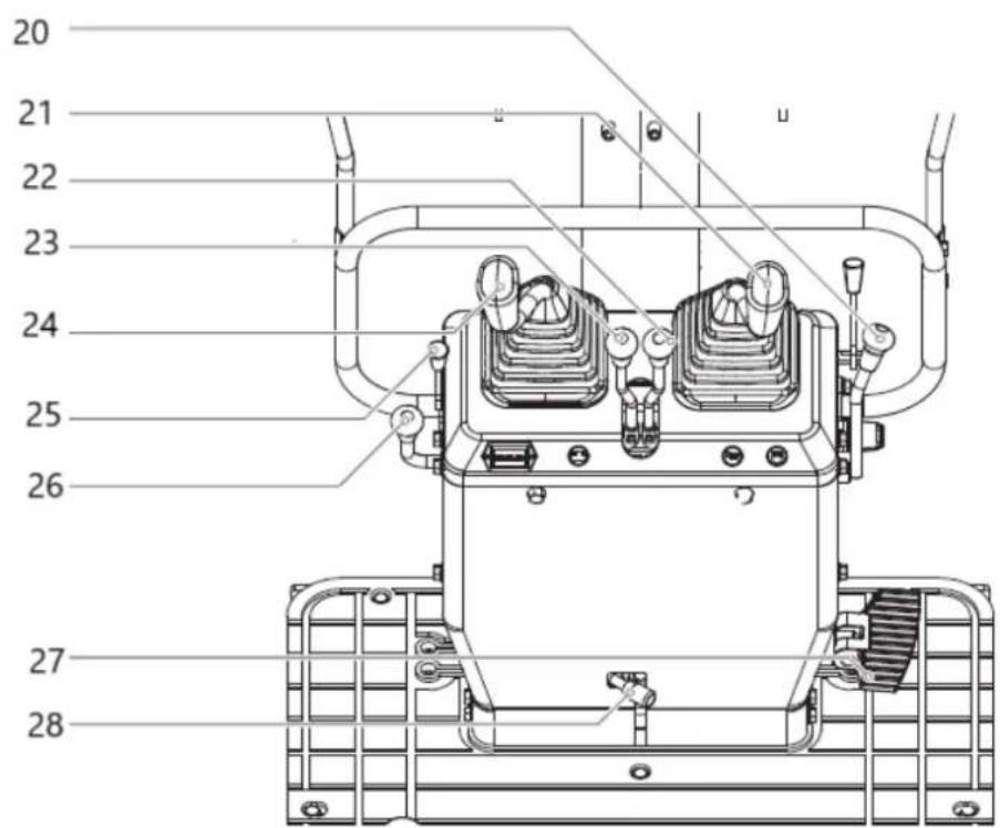
text_image
20 21 22 23 24 25 26 27 28text_image
Technical diagram of a mechanical assembly with numbered components and directional arrows indicating motion or movement.text_image
Technical diagram showing mechanical assembly with numbered components and directional arrows indicating motion or movement.1- Ouvrir
2- Verrouillage
natural_image
Technical line drawing of a mechanical device with no visible text or symbolstext_image
Technical diagram of a mechanical assembly with numbered components and directional arrows indicating motion or movement.text_image
Technical diagram of a mechanical or electrical component with numbered parts labeled 1 through 7.text_image
Technical diagram showing a mechanical control panel with labeled buttons and indicators, including symbols like '1', '2', and '3'.(1)- DÉSACTIVÉ
(2)- SUR
(3)- DÉMARRAGE
natural_image
Technical line drawing of a mechanical device with no visible text or symbolsnatural_image
Technical line drawing of a mechanical device with labeled components (no readable text or symbols)1- Compteur horaire
text_image
Technical diagram of a mechanical assembly with numbered components and directional arrows indicating motion or flow.1- Fermé
2- Robinet de carburant
3- Ouvrir

text_image
Technical diagram showing the installation of an excavator with labeled components and a downward arrow indicating process flow.text_image
Technical diagram of a mechanical assembly with numbered components and directional arrows indicating motion or movement.1- Ouvrir
2- Verrouillage
natural_image
Technical line drawing of a mechanical assembly with no visible text or symbolstext_image
Technical diagram of a tracked excavator with labeled parts and directional arrows indicating motion or assembly.natural_image
Technical diagram of a mechanical or electrical component with no visible text, numbers, or symbols.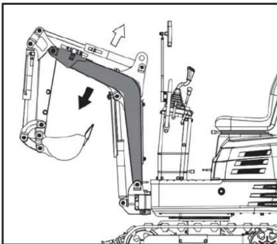
natural_image
Technical line drawing of an excavator assembly with no visible text or symbols
natural_image
Technical diagram of a mechanical or industrial system with pipes and a central component, showing directional arrows (no text or symbols)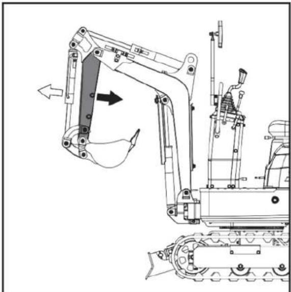
natural_image
Technical line drawing of a tracked excavator and tracked vehicle (no text or symbols)FONCTIONNEMENT DU GODET
natural_image
Technical diagram of a mechanical piping system with directional arrows indicating flow or movement (no text or labels)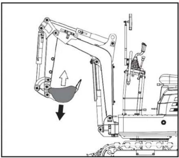
natural_image
Technical line drawing of an excavator with a downward load arrow, showing mechanical components without any text or symbols.FONCTIONNEMENT PIVOTANT (OSCILLATION DE L'UNITÉ)

ATTENTION!
natural_image
Technical diagram of a mechanical or electrical component with pipes and valves, no visible text or symbols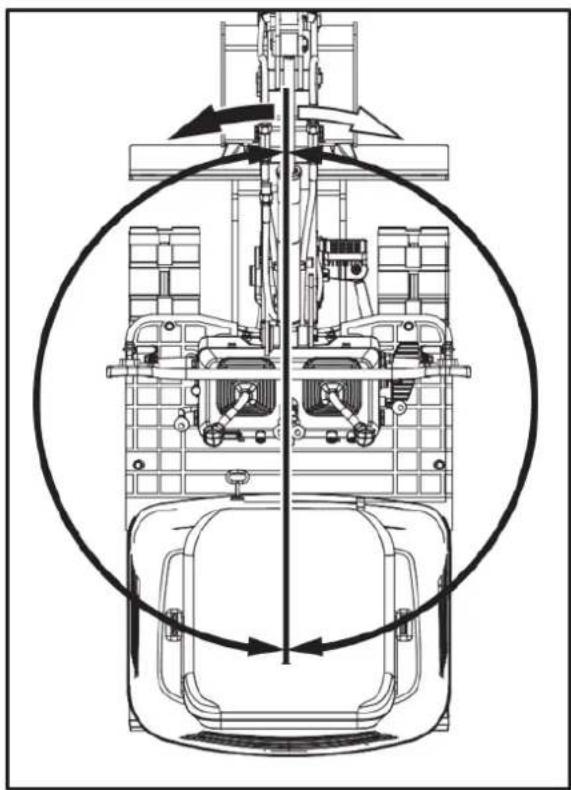
natural_image
Technical line drawing of a mechanical assembly with no visible text or symbolsFONCTIONNEMENT DE LA FLÈCHE PIVOTANTE
text_image
Technical diagram of a mechanical assembly with labeled parts A, B, and numbered components 1 and 21 - Pédale. 2 - AVANT
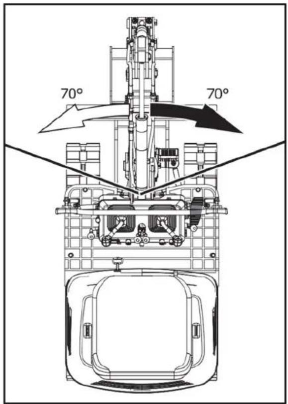
text_image
70° 70°PÉDALE DE BALANÇOIRE À FLÈCHE

natural_image
Technical line drawing of a mechanical assembly with no visible text or symbols- Réparer
FONCTIONNEMENT DU BOUTEUR
text_image
Technical diagram of a mechanical assembly with labeled parts A, B, and C, showing connections and components.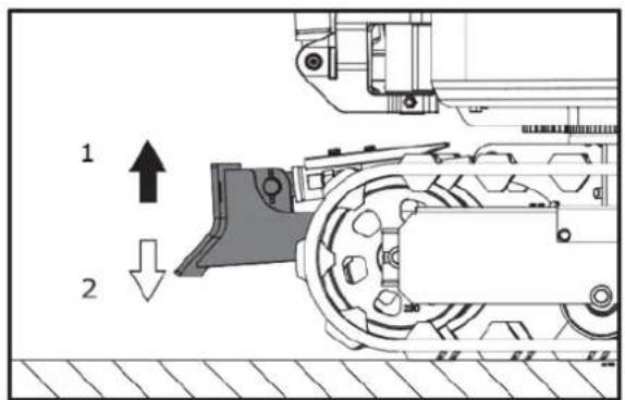
text_image
1 2natural_image
Technical line drawing of a mechanical assembly with no visible text or symbolstext_image
Technical diagram of a mechanical or electrical device with numbered components and directional arrows indicating flow or movement.natural_image
Technical line drawing of an excavator with labeled component '1' and directional arrow (no text or symbols beyond labels)natural_image
Illustration of two excavators on a construction ground, showing different mechanical configurations (no text or symbols present)
natural_image
Line drawing of a bulldozer with a cross mark indicating failure, no text or symbols presentTOURS

ATTENTION!
natural_image
Technical diagram showing a mechanical assembly with an upward arrow and a side-view view of a vehicle wheel (no text or symbols present)text_image
Technical diagram showing a device with internal components and directional arrow indicating rotation or assembly.text_image
Technical diagram showing a device with labeled components and a mechanical assembly with directional arrows.text_image
Technical diagram showing a device with labeled components and a schematic view of its internal structure.text_image
Diagram illustrating a mechanical or electrical system with labeled components and directional arrows, including a device component and a multi-view assembly.text_image
Diagram showing a device with lightbulb and directional arrows, alongside its internal structure with labeled components.natural_image
Line drawing of an excavator on a construction ground (no text or symbols)STATIONNEMENT EN PENTE

natural_image
Technical line drawing of an excavator on a sloped terrain (no text or symbols)- Cale
INFORMATIONS IMPORTANTES SUR LE FONCTIONNEMENT DE LA MACHINE

ATTENTION!
natural_image
Line drawing of an excavator on a flatbed truck, no text or symbols present
DANGER DE MORT !
natural_image
Illustration of a worker pushing a dump truck with an upward arrow indicating load or damage (no text or symbols)text_image
250 to 300 mm 300 mm 250 to 300 mm 5000 mm 250 to 300 mmnatural_image
Line drawing of a construction vehicle with an excavator on a sloped terrain (no text or symbols)text_image
Technical diagram of a machine tool with numbered components and labeled partstext_image
Technical diagram of a mechanical assembly with numbered components and directional arrows indicating motion or movement.natural_image
Cartoon illustration of a truck with an excavator and a bucket, surrounded by clouds (no text or symbols)natural_image
Technical line drawing of an excavator with labeled components (no text or symbols present)- Manille
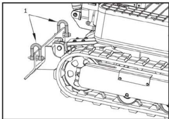
natural_image
Technical line drawing of a mechanical assembly with no visible text or symbols- Manille
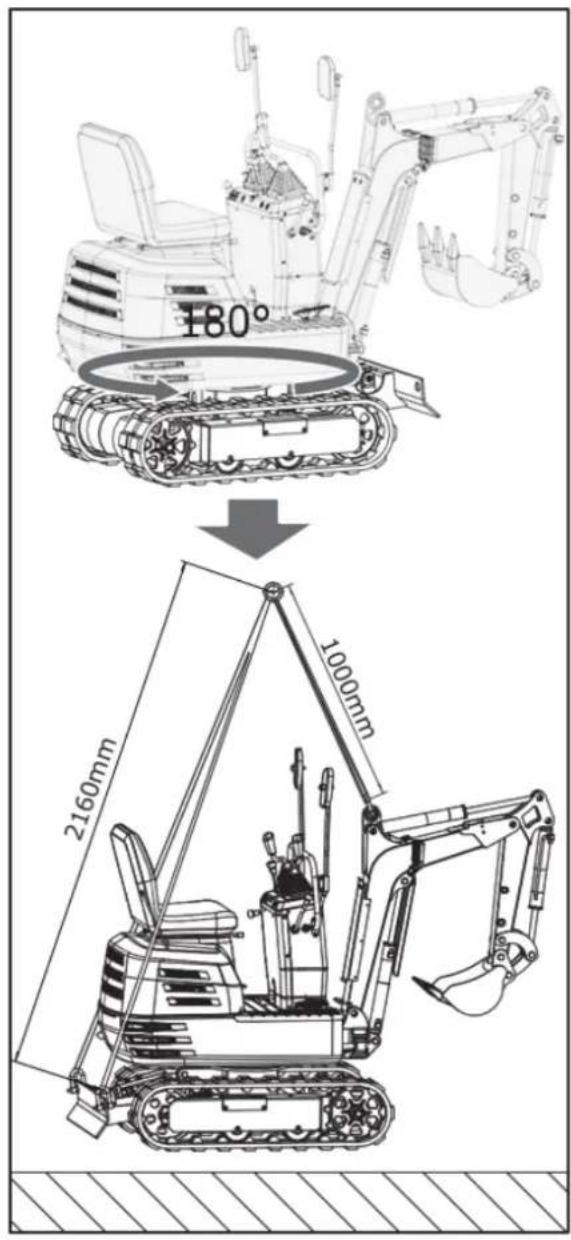
text_image
180° 2160mm 1000mmENTRETIEN
INTERVALLES D'ENTRETIEN
text_image
Technical diagram of a tracked vehicle's internal components with numbered parts and directional arrows indicating motion or movement.text_image
Technical diagram of a tractor's internal components with numbered parts labeled 1 and 2natural_image
Technical line drawing of a mechanical assembly with no visible text or symbolsnatural_image
Technical line drawing of a mechanical assembly with no visible text or symbols- Respirateur d'air
natural_image
Technical line drawing of an electric motor assembly with labeled components (no text or symbols present)natural_image
Technical line drawing of a tracked vehicle showing internal components and engine (no text or symbols)text_image
Technical diagram of a vehicle engine bay with numbered components and labeled partstext_image
Technical diagram of a tracked vehicle with labeled components and partstext_image
Technical diagram of an excavator with numbered components and labeled partsnatural_image
Technical line drawing of a mechanical assembly with labeled parts (no text or symbols present)natural_image
Technical line drawing of a mechanical assembly with no visible text or symbolsnatural_image
Technical line drawing of a bulldozer with visible tracks and components (no text or symbols)text_image
Technical diagram of a tracked vehicle showing engine, chassis, and drivetrain components with numbered parts labeled 1, 2, and 3.natural_image
Technical line drawing of a mechanical component with internal parts and mounting holes (no text or symbols)text_image
Technical diagram of a vehicle engine bay with numbered components and labeled partsnatural_image
Technical line drawing of a mechanical assembly with labeled components (no readable text or symbols)natural_image
Technical line drawing of a tracked vehicle with visible tracks, springs, and components (no text or symbols)text_image
Technical diagram of a tracked vehicle with numbered components and directional arrows indicating assembly or movement.natural_image
Silhouette of a human head with motion arrows indicating motion or sound (no text or symbols)natural_image
Line drawing of a hand using a tool to mark a grating or soldering process (no text or symbols)
natural_image
Technical line drawing of a mechanical assembly with no visible text or symbols- Bougie d'allumage
natural_image
Technical line drawing of a tracked vehicle with labeled components (no text or symbols present)- Graisseur
TOUTES LES 200 HEURES DE SERVICE
text_image
Technical diagram of a tracked vehicle with numbered components and directional arrows indicating motion or assembly.1- Boulon de fixation
natural_image
Technical line drawing of a tracked robotic vehicle with visible engine and tracks (no text or symbols)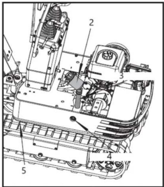
text_image
Technical diagram of a mechanical assembly with numbered components for identification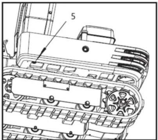
text_image
5text_image
Technical diagram of a tracked vehicle with numbered components and labeled parts1 boulon M20 × 120
2 écrous M20
3-30mm prune wench
natural_image
Technical line drawing of an excavator and tracked vehicle (no text or symbols)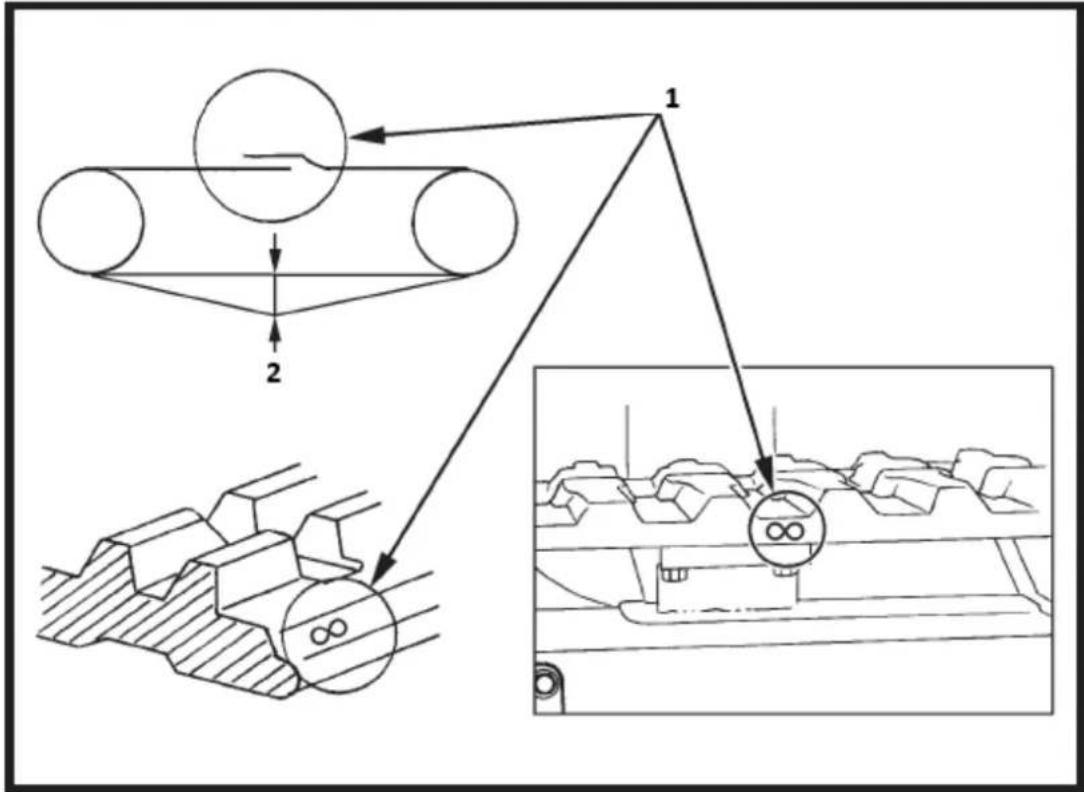
flowchart
graph TD
    A["Component 1"] --> B["Component 2"]
    B --> C["Output"]
    style A fill:#f9f,stroke:#333
    style B fill:#ccf,stroke:#333
    style C fill:#cfc,stroke:#333
text_image
Technical diagram of an engine compartment with labeled components and exploded view, showing internal parts and assembly details.text_image
Technical diagram of a mechanical device with labeled components and exploded viewsRECOMMANDATIONS DE CARBURANT
text_image
Line No 12V Rated/Black Starting Motor Fremout Line. Line No. 12y Line No. 12y Gasoline Engine Starting Line, Line No. 65 Sterling Relay Line No. 17 Redblide Line No. 17 Redblide Replace ran with the large excavator cooling fan Line No. 3-1 Line No. 3-1 Line No. 3-1 Line No. 3-1 Line No. 3-1 Line No. 3-1 Line No. 3-1 Line No. 3-1 Line No. 3-1 Line No. 3-1 Line No. 3-1 Line No. 3-1 Line No. 3-1 Line No 3-1 Line No. 3-1 Line No. 3-1 Line No. 3-1 Line No. 3-1 Line No. 3-1 Line No. 3-1 Line No. 3-1 Line No. 3-1 Line No. 3-1 Line No. 3-1 Line No. 3-1 Line No. 3-2 Line No. 3-2 Line No. 3-2 Line No. 3-2 Line No. 3-2 Line No. 3-2 Line No. 3-2 Line No. 3-2 Line No. 3-2 Line No. 3-2 Line No. 3-2 Line No. 3-2 Line No. 3-2 Line No 3-2 Line No. 3-2 Line No. 3-2 Line No. 3-2 Line No. 3-2 Line No. 3-2 Line No. 3-2 Line No. 3-2 Line No. 3-2 Line No. 3-2 Line No. 3-2 Line No. 3-2 Line No. 3-1 Line No. 3-1 Line No. 3-1 Line No. 3-1 Line No. 3-1 Line No. 3-1 Line No. 3-1 Line No. 3-1 Line No. 3-1 Line No. 3-1 Line No. 3-1 Line No. 3-1 Line No. Line No. Line No. Line No. Line No. Line No. Line No. Line No. Line No. Line No. Line No. Line No. Line No. Line No. Line No. Line No. Line No. Line No. Line No. Line No. Line No. Line No. Line No. Line No. Line No. Line No. Line No. Line No. Line No. Line No. Line No. Line No. Line No. Line No. Side Power Source: Control unit (0 to -0) and Power Source: Control unit (0 to +0) and Power Source: Control unit (0 to +0) and Power Source: Control unit (0 to +0) and Power Source: Control unit (0 to +0) and Power Source: Control unit (0 to +0) and Power Source: Control unit (0 to +0) and Power Source: Control unit (0 to +0) and Power Source: Control unit (0 to +0) and Power Source: Control unit (0 to +0) and power source: Power Source: Control unit (0 to -0) and Power Source: Control unit (0 to +0) and Power Source: Control unit (0 to +0) and Power Source: Control unit (0 to +0) and Power Source: Control unit (0 to +0) and Power Source: Control unit (0 to +0) and Power Source: Control unit (0 to +0) and Power Source: Control unit (0 to +0) and Power Source: Control Unit (0 to +0) Power Source: Control unit (0 to -0) and Power Source: Control unit (0 to +0) and Power Source: Control unit (0 to +0) and Power Source: Control unit (0 to +0) and Power Source: Control unit (0 to +0) and Power Source: Control unit (0 to +0) and Power Source: Control Unit (0 to +0) Power Source: Control unit (0 to -0) and Power Source: Control unit (0 to +0) and Power source: Control unit (0 to +0) and Power source: Control unit (0 to +0) and Power source: Control unit (0 to +0) and Power source: Control unit (0 to +0) Power Source: Control unit (0 to -0) and Power Source: Control unit (0 to +0) and Power source: Control unit (0 to +0) and Power source: Control unit (0 to +0) and Power source: Control unit (0 to +0) Power Source: Control unit (0 to -0) and Power Source: Control unit (0 to +0) and Power source: Control unit (0 to +0) and Power source: Control unit (0 to +0) and Power source: Control unit (87) Power Source: Control unit (87) Power Source: Control unit (87) Power Source: Control unit (87) Power Source: Control unit (87) Power Source: Control unit (87) Power Source: Control unit (87) Power Source: Control unit (87) Power Source: Control unit (87) Power Source: Control unit (87) Power Source: Control unit (87) Power Source: Control unit (87) Power Source: Control Unit: Control Unit: Control Unit: Control Unit: Control Unit: Control Unit: Control Unit: Control Unit: Control Unit: Control Unit: Control Unit: Control Unit: Control Unit: Control Unit: Control Unit: Control Unit: Control Unit: Control Unit: Control Unit: Control Unit: Control Unit: Control Unit: Control Unit: Control Unit: Control Unit: Control Unit: Control Unit: Control Unit: Control Unit: Control Unit: Control Unit: Control Unit: Control Unit: Control Unit:text_image
Exploded view diagram of a mechanical assembly with numbered components for identificationtext_image
Exploded view diagram of a mechanical assembly with numbered components for identificationtext_image
Technical diagram of a tracked vehicle with numbered components and assembly linestext_image
Technical diagram of a mechanical assembly with numbered components for identificationnatural_image
Technical line drawing of a tracked excavator with levers and motors (no text or symbols)natural_image
Technical line drawing of a tracked excavator assembly with mounting bracket and guide rails (no text or symbols)natural_image
Line drawing of an excavator with tracked blade and bucket (no text or symbols)natural_image
Technical line drawing of an excavator and tracked vehicle (no text or symbols)natural_image
Line drawing of an excavator with tracked base and mechanical components (no text or symbols)text_image
Technical diagram showing the assembly of an excavator with labeled components and motion arrows indicating changes.natural_image
Technical line drawing of an excavator with tracked components and control panel (no text or symbols)Pose de griffes
natural_image
Technical line drawing of an excavator with tracked base and control panel (no text or symbols)natural_image
Line drawing of an excavator with tracked base and blade assembly (no text or symbols)natural_image
Technical line drawing of an excavator with tracked base and bucket, no text or symbols presentnatural_image
Line drawing of an excavator with tracked base and attached bucket (no text or symbols)text_image
M10 x 95 x 3text_image
Diagram illustrating vehicle parking and parking rules with no restrictions on one side and a vehicle moving to the other.text_image
Technical diagram of a mechanical engine with numbered components for identification1- Silencieux
2- BOUGIE D'ALLUMAGE :
3- Étouffer
4- Couvre-culasse
5- FILTRE À AIR :
text_image
Technical diagram of a mechanical engine with numbered components labeled 1, 2, and 3text_image
Technical diagram of a mechanical engine with numbered components for identification13
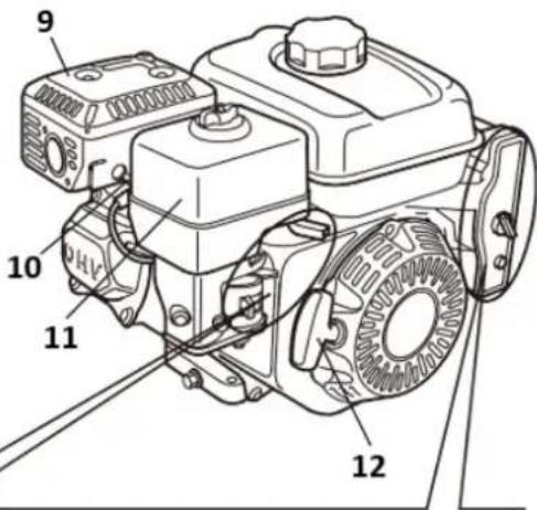
text_image
9 10 11 1213
text_image
Technical diagram of a mechanical assembly with numbered components labeled 1, 2, and 3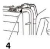
A
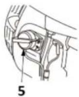
B
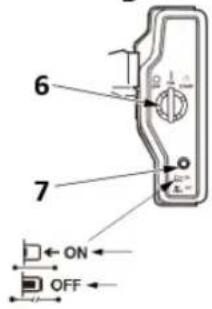
text_image
6 7 ON OFFtext_image
Technical diagram of a car air conditioner unit with labeled components and directional arrows indicating airflow or movement.text_image
1 2 3 4 5 START CLOSED CHoke OPEN1- Ouvrir
2- Levier de starter
3- Fermer
4- Ouvrir
5- Levier de starter
natural_image
Illustration of a hand turning a mechanical component with a tool, labeled '1' (no text or symbols on the diagram itself)text_image
Technical diagram of a mechanical component with numbered parts and an arrow indicating direction or motion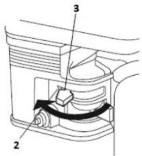
text_image
Technical diagram of a mechanical device with labeled parts 2, 3, and directional arrows indicating movement or force.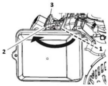
text_image
Technical diagram of a mechanical component with numbered parts and directional arrows indicating motion or flow.1- OUVRIR
2- FERMER
3- Levier de starter
text_image
Technical diagram of a mechanical assembly with numbered components and directional arrows indicating motion or force.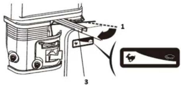
text_image
Technical diagram of a vehicle door assembly with labeled parts and component indicators1- Lent
2- Rapide
text_image
Technical diagram of a mechanical component with labeled parts and directional arrows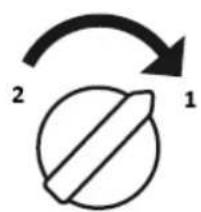
text_image
2 11- SUR
2- DÉSACTIVÉ
natural_image
Diagram of a hand turning a mechanical component with labeled parts (no text or symbols present)text_image
Technical diagram of a mechanical component with numbered parts and an arrow indicating rotational direction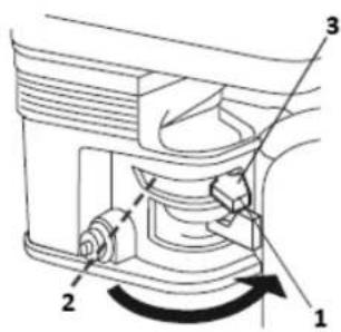
text_image
Technical diagram of a mechanical device with numbered components and directional arrows indicating motion or flow.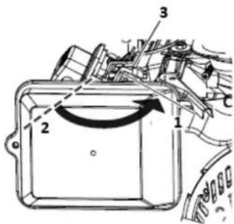
text_image
Technical diagram of a mechanical component with numbered parts and directional arrows indicating motion or movement.1- Ouvrir
2- Fermer
3- Levier de starter
Arret du moteur
text_image
Technical diagram of a mechanical assembly with numbered components labeled 1, 2, and 3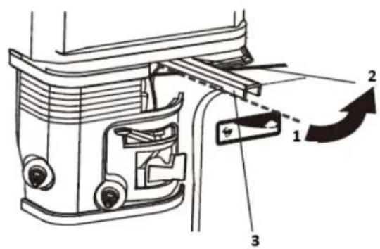
text_image
Technical diagram of a mechanical assembly with numbered components and directional arrows indicating motion or assembly.1- Rapide
2- Lent
text_image
1 2 O I 2 3 11- SUR
2- DÉSACTIVÉ
text_image
Technical diagram of a mechanical device with numbered components and directional arrows indicating motion or assembly.1- Ouvrir
2- Fermer
text_image
Technical diagram of a mechanical assembly with numbered components and directional arrows indicating motion or rotation.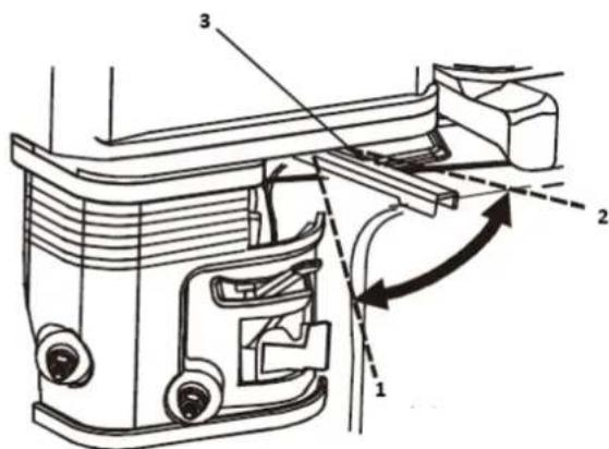
text_image
Technical diagram of a mechanical assembly with numbered components and directional arrows indicating motion or flow.1- Rapide
2- Lent
177F(E)/TR270(E)/TR306(E): 6,0 L
188F(E)/TR389(E):6,0 L
190F(E)/192F(E)/TR420(E)/TR440(E)/TR460(E):6,0 L
text_image
Technical diagram showing a mechanical assembly with labeled components and a hand operating a valve or actuator.RECOMMANDATIONS DE CARBURANT
text_image
Technical diagram showing mechanical assembly steps with labeled parts 1, 2, and 3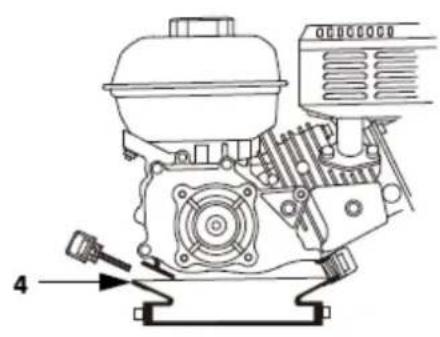
natural_image
Technical line drawing of a mechanical engine assembly (no text or symbols)text_image
Technical diagram showing mechanical assembly with labeled parts 1 and 2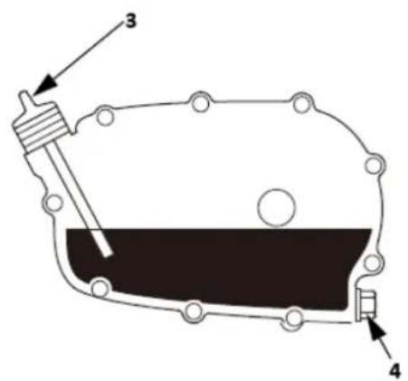
text_image
Technical diagram of a mechanical component with labeled parts 3 and 4text_image
Technical diagram of a mechanical assembly with numbered parts, likely a valve or pump component.natural_image
Illustration of hands using a handheld device to interact with a meshed device (no text or symbols present)flowchart
graph LR
    A["1 Hand washing in a bowl"] --> B["2 Downing liquid"]
    B --> C["3 Hand washing in a tray"]
    C --> D["4 Downing liquid"]
1-Nettoyer
text_image
Technical diagram of a mechanical assembly with numbered components for identification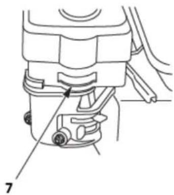
natural_image
Technical line drawing of a mechanical component with labeled parts (no text or symbols present)text_image
Diagram showing a mechanical device with labeled parts, including a piston and valve assembly.| F6RTC | F7RTC | |
| CHAMPION | RN6YC/RN6Y | RN7YC/RN7Y |
| NGK | BPR6ES | BPR7ES |
| DENSO | W20EPR_U | W22EPR_U |
| BOSCH | WR7DC | WR5DC |

text_image
Technical diagram showing mechanical assembly with labeled parts 1 and 2, likely for industrial or automotive maintenance.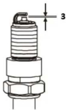
text_image
31- Clé à bougie
natural_image
Technical line drawing of a vehicle engine assembly showing valve and shaft components (no text or labels)text_image
Exploded view diagram of a mechanical assembly with numbered parts for identification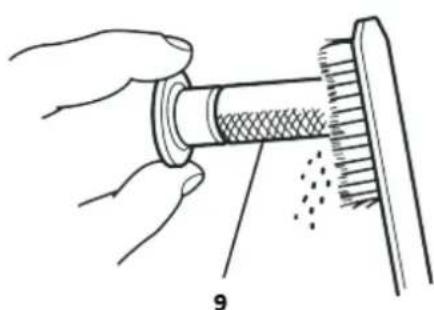
natural_image
Illustration of hands performing a mechanical tool with a meshed component and dotted texture (no text or symbols)text_image
Technical diagram of a coffee maker with labeled parts including feeding funnel, pump, and stand.text_image
Technical diagram of an automotive battery assembly with labeled parts 1, 2, and 31- CÂBLE DE BATTERIE NÉGATIF (-)
2- SOLÉNOÏDE DE DÉMARREUR
3- CÂBLE POSITIF (+) DE LA BATTERIE
text_image
Technical diagram of a sewing machine with numbered parts and exploded view, likely for assembly or maintenance instructions.1- ÉCROU DE FRICTION DU LEVIER D'ACCÉLÉRATEUR
2- RESSORT DE RETOUR
3- MONTAGE DE NOYAU DE FIL FLEXIBLE
4- MONTAGE DU NOYAU DE FIL SOLIDE
5- FIL
6- CIRCLIP de 5 mm
7- VIS 4 mm
8- SUPPORT DE FIL
9- LEVIER D'ACCÉLÉRATEUR
10- FACULTATIF
LIAISON DE STARTER À DISTANCE
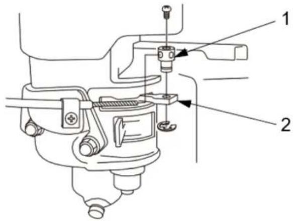
text_image
Technical diagram of a mechanical assembly with labeled parts 1 and 21- SUPPORT DE FIL
2- LEVIER DE STARTER
177F(E)/TR270(E),188F(E)/190F(E)/TR389(E)/TR420(E)/TR440(E)/TR460(E)/TR479(E)
LIAISON D'ACCÉLÉRATEUR À DISTANCE
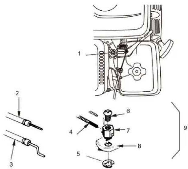
text_image
Technical diagram showing exploded and assembled parts of a mechanical device with numbered labels1- ÉCROU DE FRICTION DU LEVIER D'ACCÉLÉRATEUR
2- MONTAGE DE NOYAU DE FIL FLEXIBLE
3- MONTAGE DU NOYAU DE FIL SOLIDE
4- FIL
5- CIRCLIP de 5 mm
6- VIS 4 MM
7- SUPPORT DE FIL
8- LEVIER D'ACCÉLÉRATEUR
9- FACULTATIF
LIAISON DE STARTER À DISTANCE
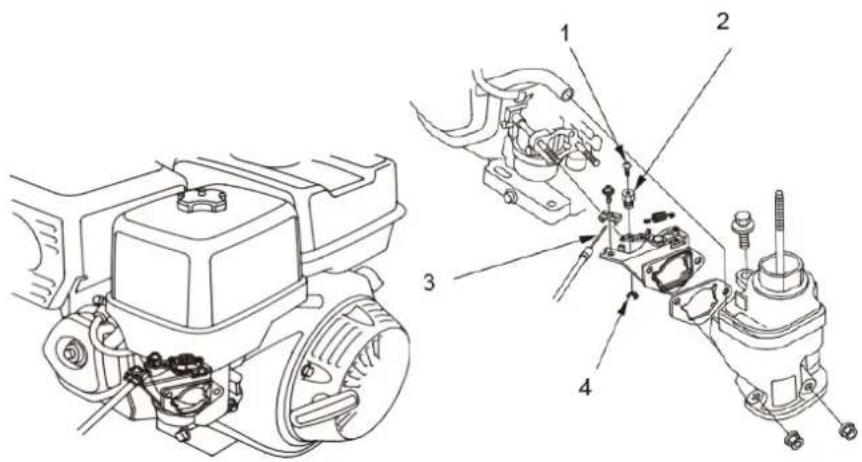
text_image
Technical diagram of engine components with numbered parts for identification1- VIS 4 mm
2- SUPPORT DE FIL
3- FIL
4- CIRCLIP de 5 mm
text_image
Diagram of a scientific apparatus with labeled components and a sensor or probe above it1-Niveau supérieur
2-Niveau inférieur

text_image
Vertical sequence of icons representing various operational or safety symbols, including battery, fuel, water, and warning signs.natural_image
Three identical robotic arm diagrams with labeled parts, shown in different angles (no text or symbols present)natural_image
Illustration of a magnifying glass examining documents with icons, no text presentTubo manuale

text_image
DANGERtext_image
Diagram illustrating three scenarios of heavy machinery collision and maintenance, with numbered instructions for each scenario.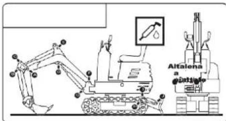
text_image
Alfalena a piatia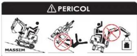
text_image
PERICOL MASSIMnatural_image
Line drawing of an excavator performing maintenance on power lines, no text or symbols presentnatural_image
Technical line drawing of an excavator on a sloped terrain (no text or symbols)natural_image
Technical line drawing of an excavator with tracked arm and base mount (no text or symbols)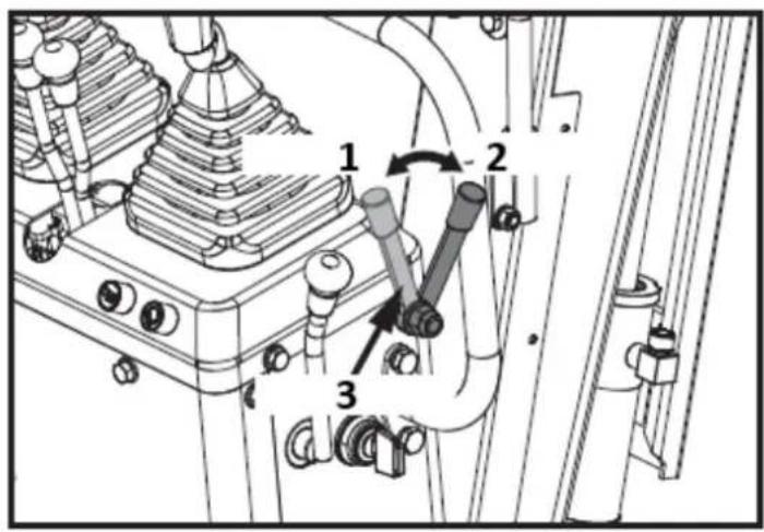
text_image
Technical diagram of a mechanical assembly with numbered components and directional arrows indicating motion or movement.text_image
Technical diagram of a mechanical assembly with numbered components and directional arrows indicating motion or flow.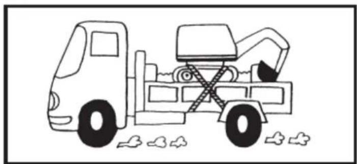
natural_image
Line drawing of a dump truck with an excavator and bucket, surrounded by clouds (no text or symbols)natural_image
Diagram of a hand holding a tool with motion arrows indicating movement (no text or symbols)natural_image
Silhouette of a human head with sunglasses and motion arrows, symbolizing vision or perception (no text or symbols)text_image
Technical diagram of a vehicle rear panel with numbered components and labeled parts
text_image
Two safety compliance symbols: one with a bird crossing over grass and another with a hand holding a glove and a person with fever.
text_image
Black-and-white pictogram of various occupational and safety symbols, including construction, hazard, and fire.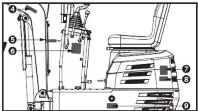
text_image
Technical diagram of an excavator with numbered components for identification and assembly reference.
text_image
4
text_image
⑤ !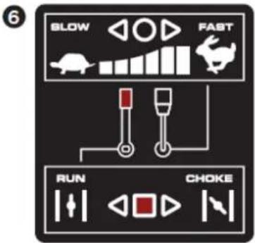
text_image
6 BLOW FAST RUN CHOKE
text_image
7 TRANSPORT Man-made Slope 3-point Lifting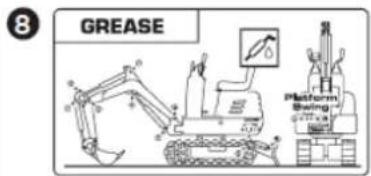
text_image
8 GREASE Platform Swing STATION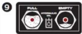
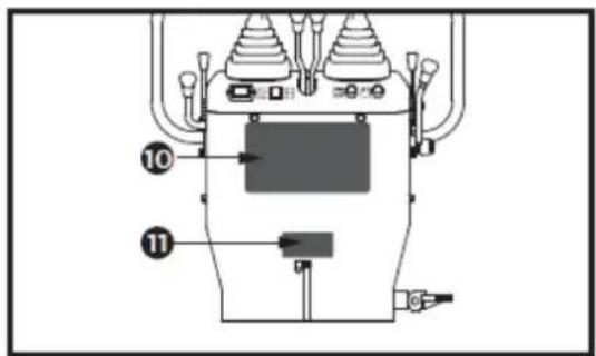
text_image
Technical diagram of a mechanical device with numbered components and labeled parts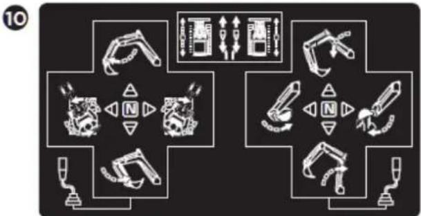
flowchart
graph TD
    A["Device 1"] --> B["Switch"]
    B --> C["Arrow to Battery"]
    C --> D["Arrow to Switch"]
    D --> E["Arrow to Switch"]
    E --> F["Arrow to Switch"]
    F --> G["Arrow to Switch"]
    G --> H["Arrow to Switch"]
    H --> I["Arrow to Switch"]
    I --> J["Arrow to Switch"]
    J --> K["Arrow to Switch"]
    K --> L["Arrow to Switch"]
    L --> M["Arrow to Switch"]
    M --> N["Arrow to Switch"]
    N --> O["Arrow to Switch"]
    O --> P["Arrow to Switch"]
    P --> Q["Arrow to Switch"]
    Q --> R["Arrow to Switch"]
    R --> S["Arrow to Switch"]
    S --> T["Arrow to Switch"]
    T --> U["Arrow to Switch"]
    U --> V["Arrow to Switch"]
    V --> W["Arrow to Switch"]
    W --> X["Arrow to Switch"]
    X --> Y["Arrow to Switch"]
11
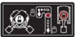
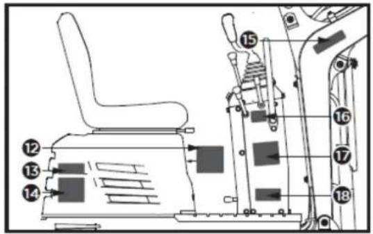
text_image
Technical diagram of an industrial machine with numbered components for identification12
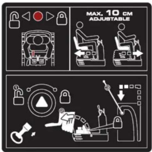
text_image
MAX. 10 CM ADJUSTABLE13
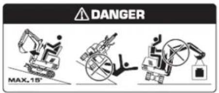
text_image
DANGER MAX.18°17
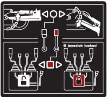
text_image
5 joystick looked14
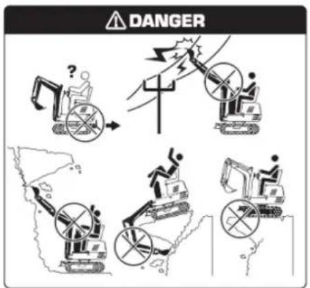
text_image
DANGER18
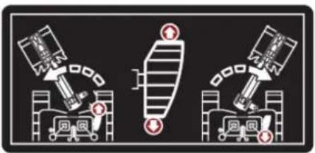
natural_image
Three diagrams showing robotic arm movements with no text or symbols15

text_image
Four warning symbols: warning triangle with exclamation mark, triangular warning triangle with broken tool, broken tool with broken handle, and broken handle with broken handle.16
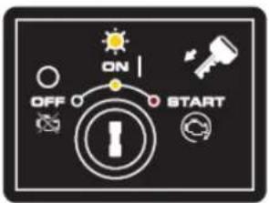
text_image
ON OFF STARTtext_image
Technical diagram of a mechanical device with labeled components and numbered parts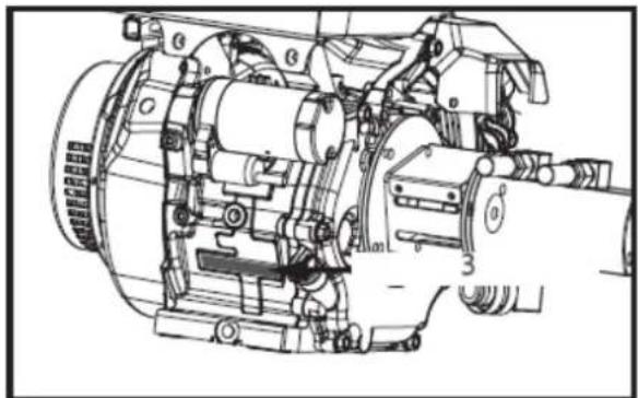
natural_image
Technical line drawing of a mechanical assembly with no visible text or symbolstext_image
Technical diagram showing a multi-step construction of an excavator with labeled tool positions and dimensions.1- Bullone M12 (x1)
3.12. Contenuto fornito
text_image
Technical diagram of an excavator with labeled parts including base, guide, and support componentstext_image
1 2 A 24mm 13mm 4mmtext_image
Technical diagram of a mechanical device with labeled parts and a 16mm wrench icon1- Bullone M10x20 (x4)
text_image
X 2 13mm 1 C1- Bullone M8x30 (x4)
natural_image
Technical line drawing of a vehicle's internal components, showing a seat assembly and engine compartment (no text or symbols)text_image
Technical diagram of an excavator with numbered parts for identification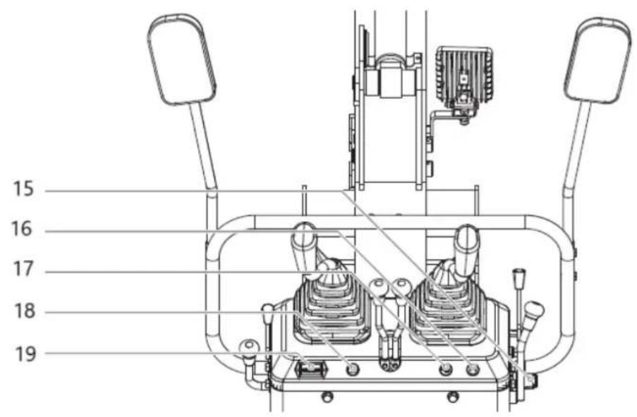
text_image
15 16 17 18 19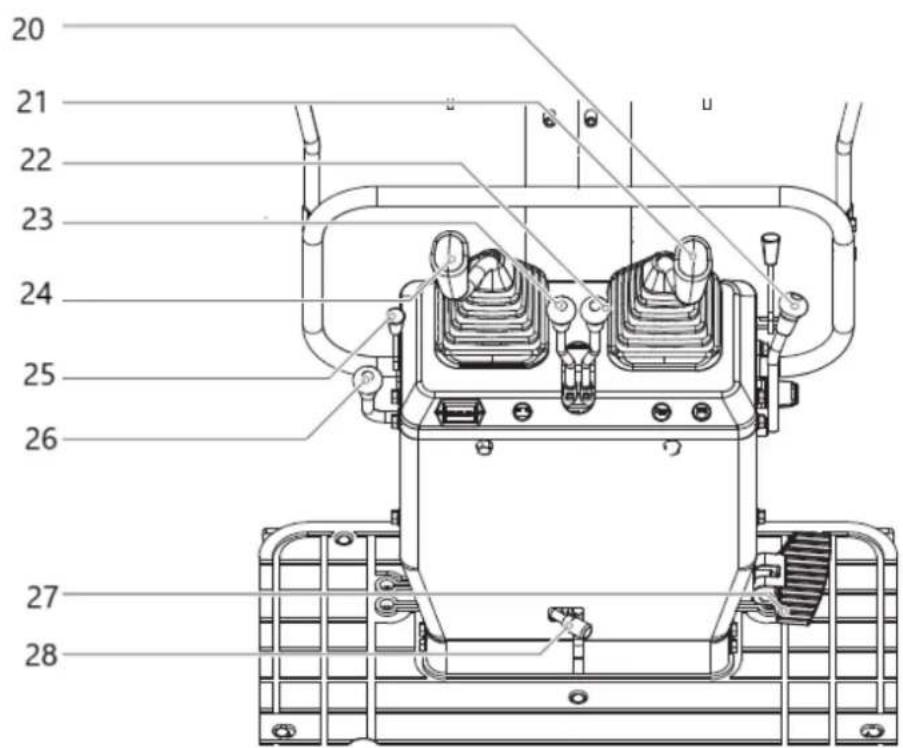
text_image
20 21 22 23 24 25 26 27 28text_image
Technical diagram of a mechanical assembly with numbered components and directional arrows indicating motion or movement.1- Sbloccare
2- Blocco
text_image
Technical diagram showing mechanical assembly with numbered components and directional arrows indicating motion or movement.1- Sbloccare
2- Blocco
natural_image
Technical line drawing of a mechanical device with no visible text or symbolstext_image
Technical diagram of a mechanical assembly with numbered components and directional arrows indicating motion or movement.1- Chiuso
2- Rubinetto del carburante
3- Aprire
text_image
Technical diagram of a mechanical or electrical component with numbered parts labeled 1 through 7.text_image
Technical diagram of a mechanical assembly with labeled components and an inset showing a circular component with symbols 1, 2, 3 and a switch symbol.(1)- SPENTO
(2)- SOPRA
(3)- INIZIO
natural_image
Technical line drawing of a mechanical or electrical component with no visible text or symbolsnatural_image
Technical line drawing of a mechanical device with no visible text or symbols1- Contaore
text_image
Technical diagram of a mechanical assembly with numbered components and directional arrows indicating motion or flow.1- Chiuso
2- Rubinetto del carburante
3- Aprire

text_image
Technical diagram showing a mechanical excavator assembly with labeled parts and a downward arrow indicating process flow.text_image
Technical diagram of a mechanical assembly with numbered components and directional arrows indicating motion or movement.natural_image
Technical line drawing of a mechanical assembly with no visible text or symbolstext_image
Technical diagram of an excavator with labeled parts and directional arrows indicating motion or assembly.natural_image
Technical diagram of a mechanical or electrical component with no visible text, numbers, or symbols.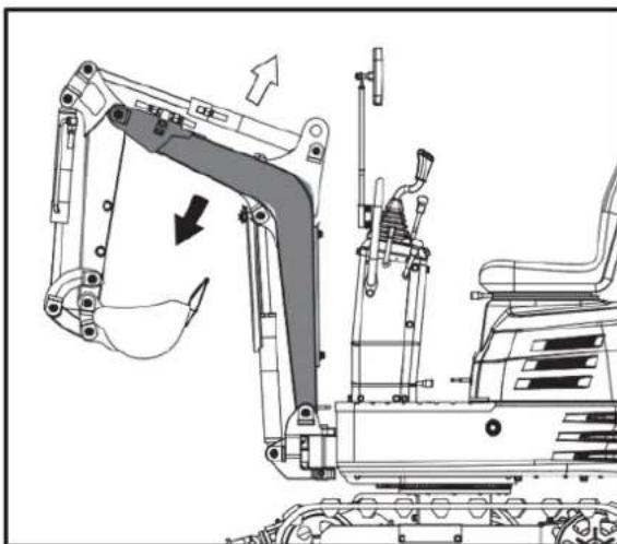
natural_image
Technical line drawing of an excavator assembly with no visible text or symbols
natural_image
Technical diagram of a piping system with valves and a valve, showing internal components and directional arrows (no text or labels)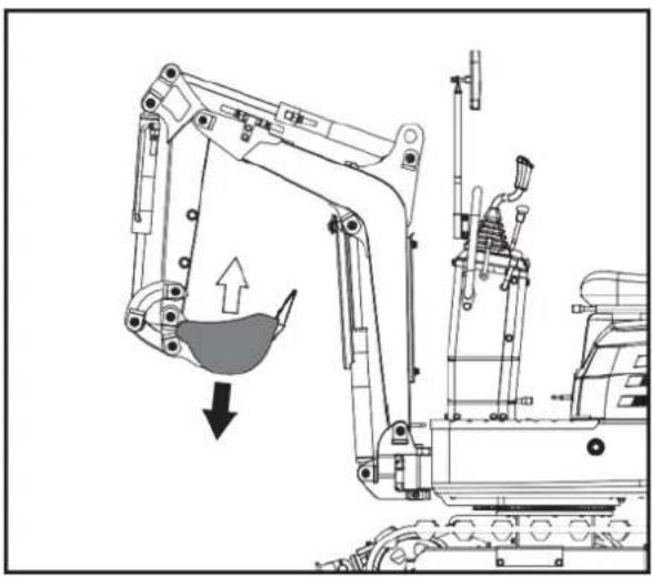
natural_image
Technical line drawing of an excavator with a downward load arrow, showing mechanical components and structural details (no text or symbols)natural_image
Technical diagram of a mechanical or electrical component with pipes and valves, showing internal structure and directional arrow (no text or symbols)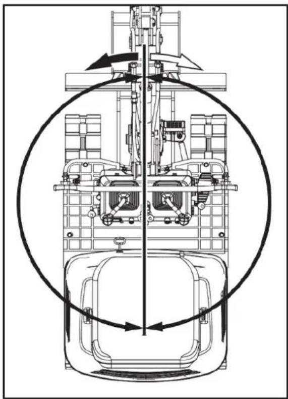
natural_image
Technical line drawing of a mechanical assembly with no visible text or symbolstext_image
Technical diagram of a mechanical assembly with labeled parts A, B, and numbered components 1 and 21 - Pedale. 2 - ANTERIORE
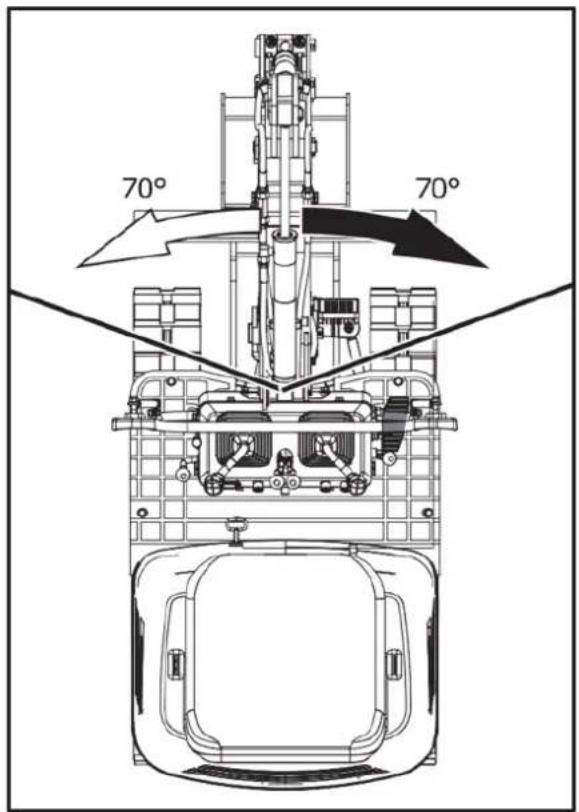
text_image
70° 70°PEDALE BOOM SWING

natural_image
Technical line drawing of a mechanical assembly with no visible text or symbols- Aggiustare
text_image
Technical diagram of a mechanical assembly with labeled components A, B, and numbered parts ① to ⑨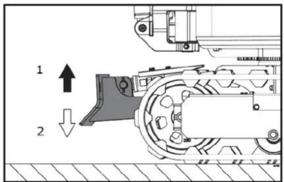
text_image
1 2natural_image
Technical diagram of a mechanical assembly with labeled component '1' (no text or symbols beyond label)1. Fronte
text_image
Technical diagram of a mechanical device with numbered components and directional arrows indicating flow or movement.natural_image
Technical line drawing of an excavator and tracked vehicle (no text or symbols)natural_image
Two excavators in action poses with arrows indicating motion, no text or symbols present
natural_image
Line drawing of a bulldozer with a cross mark indicating failure, no text or symbols presentGIRI

ATTENZIONE!
natural_image
Technical diagram showing a mechanical assembly with an upward arrow and a side-view view of a vehicle wheel (no text or symbols present)text_image
Technical diagram showing a device with internal components and a directional arrow indicating rotation or assembly.text_image
Technical diagram showing a device with labeled components and a mechanical assembly with directional arrows.text_image
Technical diagram showing a device with labeled components and a mechanical assembly with parts numbered 1 and 2.text_image
Diagram showing a device with directional arrows and a mechanical assembly, labeled with components 1 and 2.- Virata a sinistra. 2. Virata a sinistra.
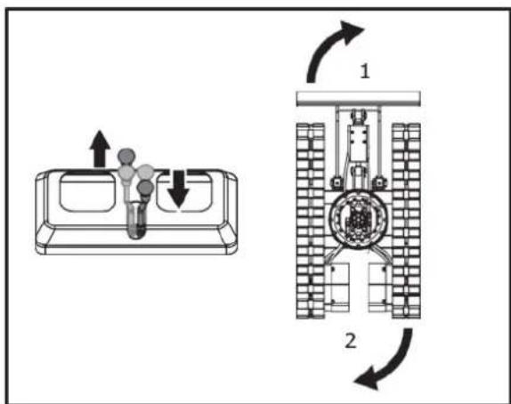
text_image
Diagram showing a device with lightbulb and directional arrows, alongside its internal structure with labeled components.- Virata a destra. 2. Virata a destra.
VIAGGIARE IN SALITA E DISCESA
natural_image
Line drawing of an excavator on a construction ground (no text or symbols)PARCHEGGIO IN PENDENZA

natural_image
Technical line drawing of an excavator on a sloped terrain (no text or symbols)- Cuneo
natural_image
Line drawing of an excavator on a flatbed truck, no text or symbols present
PERICOLO DI VITA!
natural_image
Illustration of a construction worker using a flatbed truck to lift or lift material (no text or symbols)text_image
250 to 300 mm 300 mm 250 to 300 mm 5000 mm 250 to 300 mmnatural_image
Line drawing of an excavator on a flatbed truck, no text or symbols presenttext_image
Technical diagram of a machine tool with numbered components and labeled partstext_image
Technical diagram of a mechanical assembly with numbered components and directional arrows indicating motion or movement.natural_image
Cartoon illustration of a dump truck with an excavator and bucket, surrounded by clouds (no text or symbols)natural_image
Technical line drawing of an excavator with labeled components (no text or symbols present)- Catena
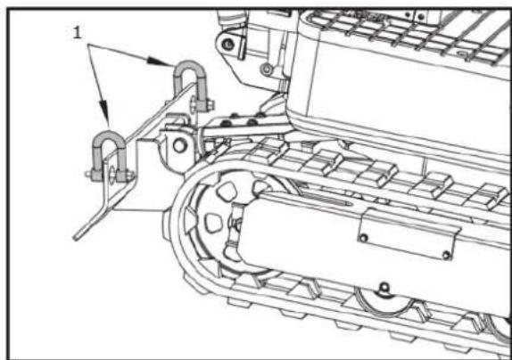
natural_image
Technical line drawing of a mechanical assembly with no visible text or symbols- Catena
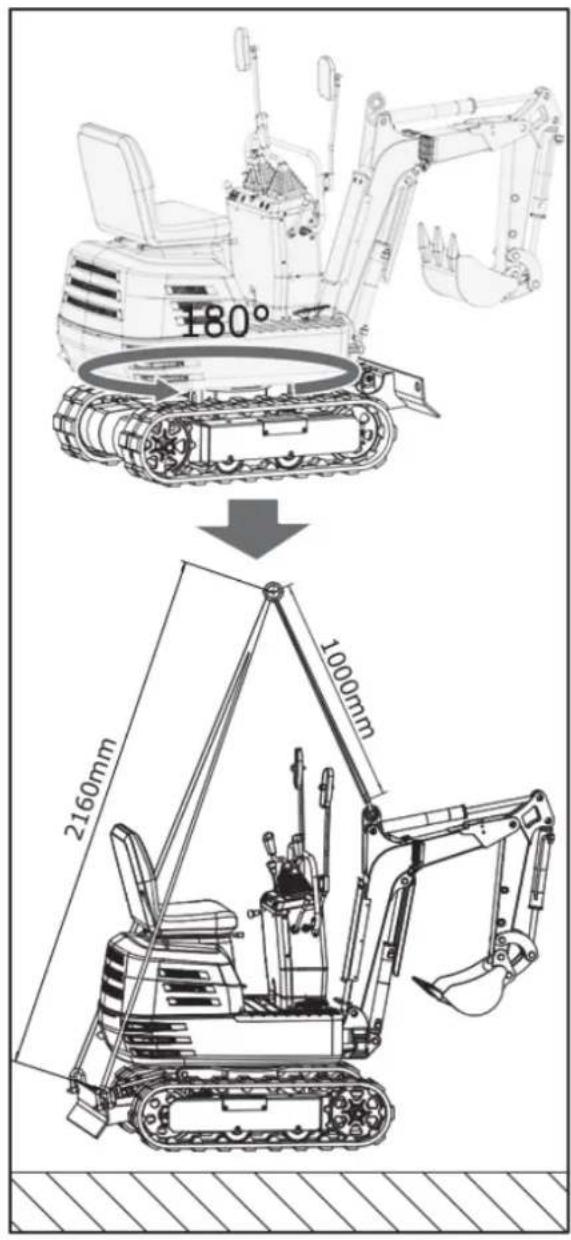
text_image
180° 2160mm 1000mmMANUTENZIONE
text_image
Technical diagram of a vehicle's front-mounted truck with numbered components and directional arrows indicating motion or movement.text_image
Technical diagram of a tractor's internal components with numbered parts labeled 1 and 2natural_image
Technical line drawing of a vehicle engine bay with visible components and no text or symbolsnatural_image
Technical line drawing of a mechanical assembly with no visible text or symbolsnatural_image
Technical line drawing of an electric motor assembly with labeled components (no text or symbols present)natural_image
Technical line drawing of a tracked vehicle showing internal components and engine (no text or symbols)text_image
Technical diagram of a vehicle engine bay with numbered components and labeled partstext_image
Technical diagram of a tracked vehicle with labeled parts, showing mechanical components and assembly details.text_image
Technical diagram of an excavator with labeled parts including arm, bucket, and guide componentsnatural_image
Technical line drawing of a mechanical assembly with labeled parts (no text or symbols present)natural_image
Technical line drawing of a mechanical assembly with no visible text or symbolsnatural_image
Technical line drawing of a bulldozer with visible mechanical components and tool path (no text or symbols)text_image
Technical diagram of a tracked vehicle showing engine, motors, and structural components with numbered labelsnatural_image
Technical line drawing of a mechanical component with internal parts and mounting holes (no text or symbols)text_image
Technical diagram of a vehicle engine bay with numbered components and labeled partsnatural_image
Technical line drawing of a mechanical assembly with labeled component '1' (no text or symbols beyond label)natural_image
Technical line drawing of a tracked vehicle with visible tracks and components (no text or symbols)text_image
Technical diagram of a tracked vehicle with numbered components and directional arrows indicating assembly or inspection.natural_image
Silhouette of a human head with arrows indicating airflow or pressure direction (no text or symbols)natural_image
Line drawing of a hand using a tool to mark a grating on a rectangular plate (no text or symbols)
natural_image
Technical line drawing of a mechanical assembly with no visible text or symbols- Candela
Servizio candele
natural_image
Technical line drawing of a tracked vehicle with labeled components (no text or symbols present)- Ingrassatore
text_image
Technical diagram of a tracked vehicle with numbered components and directional arrows indicating motion or assembly.natural_image
Technical line drawing of a tracked robotic vehicle with visible engine and tracks (no text or symbols)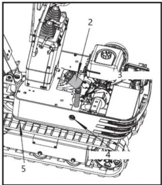
text_image
Technical diagram of a mechanical assembly with numbered components for identification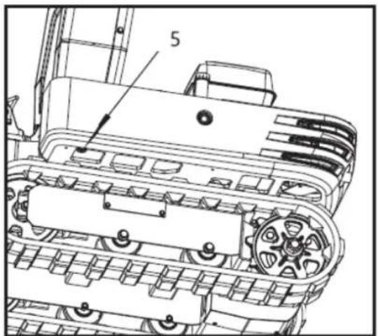
text_image
5text_image
Technical diagram of a tracked vehicle with numbered components and labeled parts1-Bullone M20 × 120
2-dado M20
3-30mm prugna ragazza
natural_image
Technical line drawing of an excavator and tracked vehicle (no text or symbols)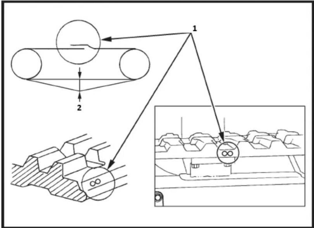
flowchart
graph TD
    A["Transmission Belt"] --> B{Check Point}
    B --> C["Gear Mechanism"]
    C --> D["Output Inspection"]
    D --> E["Final Output"]
text_image
Technical diagram of an automotive engine with labeled components and exploded viewtext_image
Technical diagram of a mechanical device with labeled components and exploded viewstext_image
Line No 12V Rated/Black Starting Motor Fermostat Line. Line No. 12y Line No. 26c Sterling Relay Gasoline Engine Starting Line, Line No. 85 Line No. 12y Line No. 17 Redblie Line No. 17 Redblie Litter PSB 26T Replace ran with the large exchanger cooling fan Line No. 3-1 Line No. 3-1 Line No. 3-1 Line No. 3-1 Line No. 3-1 Line No. 3-1 Line No. 3-1 Line No. 3-1 Line No. 3-1 Line No. 3-1 Line No. 3-1 Line No. 3-1 Line No. 3-1 Line No 3-1 Line No. 3-1 Line No. 3-1 Line No. 3-1 Line No. 3-1 Line No. 3-1 Line No. 3-1 Line No. 3-1 Line No. 3-1 Line No. 3-1 Line No. 3-1 Line No. 3-1 Line No. 3-2 Line No. 3-2 Line No. 3-2 Line No. 3-2 Line No. 3-2 Line No. 3-2 Line No. 3-2 Line No. 3-2 Line No. 3-2 Line No. 3-2 Line No. 3-2 Line No. 3-2 Line No. 3-2 Line No 3-2 Line No. 3-2 Line No. 3-2 Line No. 3-2 Line No. 3-2 Line No. 3-2 Line No. 3-2 Line No. 3-2 Line No. 3-2 Line No. 3-2 Line No. 3-2 Line No. 3-2 Line No. 3-1 Line No. 3-1 Line No. 3-1 Line No. 3-1 Line No. 3-1 Line No. 3-1 Line No. 3-1 Line No. 3-1 Line No. 3-1 Line No. 3-1 Line No. 3-1 Line No. 3-1 Line No. Line No. Line No. Line No. Line No. Line No. Line No. Line No. Line No. Line No. Line No. Line No. Line No. Line No. Line No. Line No. Line No. Line No. Line No. Line No. Line No. Line No. Line No. Line No. Line No. Line No. Line No. Line No. Line No. Line No. Line No. Line No. Line No. Line No. Side Power Source: Control unit (0) Side Power Source: Control unit (0) Side Power Source: Control unit (0) Side Power Source: Control unit (0) Side Power Source: Control unit (0) Side Power Source: Control unit (0) Side Power Source: Control unit (0) Side Power Source: Control unit (0) Side Power Source: Control unit (0) Side Power Source: Control unit (0) Side Power Source: Control unit (0) Side Power Source: Control unit (0) Soldering Coil: Control unit (0) Soldering Coil: Control unit (0) Soldering Coil: Control unit (0) Soldering Coil: Control unit (0) Soldering Coil: Control unit (0) Soldering Coil: Control unit (0) Soldering Coil: Control unit (0) Soldering Coil: Control unit (0) Soldering Coil: Control unit (0) Soldering Coil: Control unit (0) Soldering coil: Control unit (0) Soldering coil: Control unit (0) Soldering coil: Control unit (0) Soldering coil: Control unit (0) Soldering coil: Control unit (0) Soldering coil: Control unit (0) Soldering coil: Control unit (0) Soldering coil: Control unit (0) Soldering coil: Control unit (0) Soldering coil: Control unit (0) Soldering wire: Control unit (0) Soldering wire: Control unit (0) Soldering wire: Control unit (0) Soldering wire: Control unit (0) Soldering wire: Control unit (0) Soldering wire: Control unit (0) Soldering wire: Control unit (0) Soldering wire: Control unit (0) Soldering wire: Control unit (0) Soldering wire: Control unit (0) Soldering line: Control unit (0) Soldering line: Control unit (0) Soldering line: Control unit (0) Soldering line: Control unit (0) Soldering line: Control unit (0) Soldering line: Control unit (0) Soldering line: Control unit (0) Soldering line: Control unit (0) Soldering line: Control unit (0) Soldering line: Control unit (0) Soldering wire: Control unit (0) Soldering wire: Control unit (0) Soldering wire: Control unit (0) Soldering wire: Control unit (0) Soldering wire: Control unit (0) Soldering wire: Control unit (0) Soldering wire: Control unit (0) Soldering wire: Control unit (0) Soldering wire: Control unit (0) Soldering wires: Control unit (0) Soldering wires: Control unit (0) Soldering wires: Control unit (0) Soldering wires: Control unit (0) Soldering wires: Control unit (0) Soldering wires: Control unit (0) Soldering wires: Control unit (0) Soldering wires: Control unit (0) Soldering wires: Control unit (0) Soldering wires: Control unit (0) Soldering wire: Control unit (0) Soldering wire: Control unit (0) Soldering wire: Control unit (0) Soldering wire: Control unit (0) Soldering wire: Control unit (0) Soldering wire: Control unit (0) Soldering wire: Control unit (0) Soldering wire: Control unit (0) Soldering wire: Control unit (0) Soldering cable: C - C - C - C - C - C - C - C - C - C - C - C - C - C - C - C - C - C - C - C - C - C - C - C - C - C - C - C - C - C - C - C - C - C - C - C - C - C - C - C - C - C - C - C - C - C - C - C - C - C - C - D - D - D - D - D - D - D - D - D - D - D - D - D - D - D - D - D - D - D - D - D - D - D - D - D - D - D - D - D - D - D - D - D - D - D - D - D - D - D - D - D - D - D - D - D - D - D - D - D - D - E - E - E - E - E - E - E - E - E - E - E - E - E - E - E - E - E - E - E - E - E - E - E - E - E - E - E - E - E - E - E - E - E - E - E - E - E - E - E | Eagle Lock Switch: Open to be standardized by the electric shock switch and the electric shock switch is closed at the minimum voltage level to be open to the minimum voltage level below the minimum voltage level above the minimum voltage level below the minimum voltage level above the minimum voltage level above the minimum voltage level above the minimum voltage level above the minimum voltage level above the minimum voltage level above the minimum voltage level above the minimum voltage level above the minimum voltage level above the minimum voltage level above the minimum voltage level above the minimum voltage level above the minimum voltage level above the minimum voltage level above the minimum voltage level above the minimum voltage level above the minimum voltage level above the minimum voltage level above the minimum voltage level above the minimum voltage level above the minimum voltage level below the minimum voltage level below the minimum voltage level below the minimum voltage level below the minimum voltage level below the minimum voltage level below the minimum voltage level below the minimum voltage level below the minimum voltage level below the minimum voltage level below the minimum voltage level below the minimum voltage level below the minimum voltage level below the minimum voltage level below the minimum voltage level below the minimum voltage level below the minimum voltage level below the minimum voltage level below the minimum voltage level below the minimum voltage level below the minimum voltage level above the minimum voltage level above the minimum voltage level above the minimum voltage level above the minimum voltage level above the minimum voltage level above the minimum voltage level above the minimum voltage level above the minimum voltage level above the minimum voltage level above the minimum voltage level above the minimum voltage level above the minimum voltage level above the minimum voltage level above the minimum voltage level above the minimum voltage level above the minimum voltage level above the minimum voltage level above the minimum voltage level below the minimum voltage level above the minimum voltage level above the minimum voltage level above the minimum voltage level above the minimum voltage level above the minimum voltage level above the minimum voltage level above the minimum voltage level above the minimum voltage level above the minimum voltage level above the minimum voltage level above the minimum voltage level above the minimum voltage level above the minimum voltage level above the minimum voltage level above the minimum voltage level above the minimum voltage level above the minimum voltage level below the minimum voltage level below the minimum voltage level above the minimum voltage level above the minimum voltage level above the minimum voltage level above the minimum voltage level above the minimum voltage level above the minimum voltage level above the minimum voltage level above the minimum voltage level below the maximum voltage level below the maximum voltage level below the maximum voltage level below the maximum voltage level below the maximum voltage level below the maximum voltage level below the maximum voltage level below the maximum voltage level below the maximum voltage level below the maximum voltage level below the maximum voltage level below the maximum voltage level below the maximum voltage level below the maximum voltage level below the maximum voltage level below the maximum voltage level below the maximum voltage level below the maximum voltage level below the maximum voltage level below the maximum voltage level below the minimum current source in a constant type of electric shock switch and a constant type of electric shock switch and a constant type of electric shock switch and a constant type of electric shock switch and a constant type of electric shock switch and a constant type of electric shock switch and a constant type of electric shock switch and a constant type of electric shock switch and a constant type of electric shock switch and a constant type of electric shock switch and a constant type of electric shock switch and a constant type of electric shock switch and a constant type of electric shock switch and a constant type, on an electric shock switch, on an electric shock switch, on an electric shock switch, on an electric shock switch, on an electric shock switch, on an electric shock switch, on an electric shock switch, on an electric shock switch, on an electric shock switch, on an electric shock switch, on an electric shock switch, on an electric shock switch, on an electric shock switch, on an electric shock switch, on an electric shock switch, on an electric shock switch, on an electric shock switch, on an Electric shock switch, on an Electric shock switch, on an Electric shock switch, on an Electric shock switch, on an Electric shock switch, on an Electric shock switch, on an Electric shock switch, on an Electric shock switch, on an Electric shock switch, on an Electric shock switch, on an Electric shock switch, on an Electric shock switch, on an Electric shock switch, on an Electric shock switch, on an Electric shock switch, on an Electric shock switch, on an Electric shock switch, or an Electric shock switch, on an Electric shock switch, on an Electric shock switch, on an Electric shock switch, on an Electric shock switch, on an Electric shock switch, on an Electric shock switch, on an Electric shock switch, on an Electric shock switch, on an Electric shock switch, on an Electric shock switch, on an Electric shock switch, on an Electric shock switch, on an Electric shock switch, on an Electric shock switch, on an Electric shock switch, on an Electric shock Switch, on an Electric Shock Switch, on an Electric Shock Switch, on an Electric Shock Switch, on an Electric Shock Switch, on an Electric Shock Switch, on an Electric Shock Switch, on an Electric Shock Switch, on an Electric Shock Switch, on an Electric Shock Switch, on an Electric Shock Switch, on an Electric Shock Switch, on an Electric Shock Switch, on an Electric Shock Switch, on an Electric Shock Switch, on an Electric Shock Switch, on an Electric Shock Switch, on an Electric Shock Switch, on a Electric Shock Switch, on a Electric Shock Switch, on a Electric Shock Switch, on a Electric Shock Switch, on a Electric Shock Switch, on a Electric Shock Switch, on a Electric Shock Switch, on a Electric Shock Switch, on a Electric Shock Switch, on a Electric Shock Switch, on a Electric Shock Switch, on a Electric Shock Switch, on a Electric Shock Switch, on a Electric Shock Switch, on a Electric Shock Switch, on a Electric Shock Switch, on a Electric Shock Switch, C + B + C + D + E + F + G + H + I + J + K + L + M + N + O + P + Q + R + S + T + U + V + W + X + Y + Z + AA + AB + AC + AD + AE + AF + AG + AH + AI + AJ + AK + AL + AM + AN + AO + AP + AQ + AR + AS + AT + AU + AV + AW + AX + AY + AZ + BA + BC + BA + CA + CA + CA + CA + CA + CA + CA + CA + CA + CA + CA + CA + CA + CA + CA + CA + CA + CA + CA + CA + CA + CA + CA + CA + CA + CA + CA + CA + CA + CA + CA + CA + CA + CA + CA + CA + CA + CA + CA + CA + CA + CA + CA + CA + CA + CA + CA + CA + CA + CA + Ca| N. | Colore | Diametro | N. | Colore | Diametro |
| 0 | Nero | 1,5 mm^2 | 1217 | GrigioRosso/Blu | 1,0 mm^2 1,5 mm^2 |
| 3 | Rosso/Bianco | 1,0mm^2 | Si5 | Bianco/Rosso | 1,5 mm^2 |
| 5 | Giallo/Bianco | 1,0mm^2 | C6 | Verde/Rosso | 1,5 mm^2 |
| 6 | Giallo | 1,0mm^2 | 12V | Rosso/Nero | 1,5 mm^2 |
| 7 | Blu/Bianco | 1,0mm^2 | Si4 | Rosa | 1,5 mm^2 |
3.26. Schema del sistema idraulico
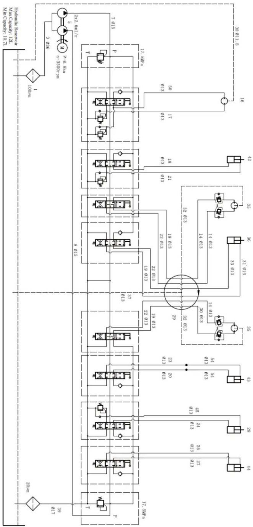
flowchart
graph TD
    A["17.5MPa"] --> B["8 015"]
    B --> C["37 013"]
    C --> D["22 013"]
    D --> E["19 013"]
    E --> F["22 013"]
    F --> G["19 013"]
    G --> H["22 013"]
    H --> I["19 013"]
    I --> J["22 013"]
    J --> K["19 013"]
    K --> L["22 013"]
    L --> M["19 013"]
    M --> N["22 013"]
    N --> O["19 013"]
    O --> P["22 013"]
    P --> Q["19 013"]
    Q --> R["22 013"]
    R --> S["19 013"]
    S --> T["22 013"]
    T --> U["19 013"]
    U --> V["22 013"]
    V --> W["19 013"]
    W --> X["22 013"]
    X --> Y["19 013"]
    Y --> Z["22 013"]
    Z --> AA["19 013"]
    AA --> AB["22 013"]
    AB --> AC["19 013"]
    AC --> AD["22 013"]
    AD --> AE["19 013"]
    AE --> AF["22 013"]
    AF --> AG["19 013"]
    AG --> AH["22 013"]
    AH --> AI["19 013"]
    AI --> AJ["22 013"]
    AJ --> AK["19 013"]
    AK --> AL["22 013"]
    AL --> AM["19 013"]
    AM --> AN["22 013"]
    AN --> AO["19 013"]
    AO --> AP["22 013"]
    AP --> AQ["19 013"]
    AQ --> AR["22 013"]
    AR --> AS["19 013"]
    AS --> AT["22 013"]
    AT --> AU["19 013"]
    AU --> AV["22 013"]
    AV --> AW["19 013"]
    AW --> AX["22 013"]
    AX --> AY["19 013"]
    AY --> AZ["22 013"]
    AZ --> BA["19 013"]
    BA --> BB["22 013"]
    BB --> BC["19 013"]
    BC --> BD["22 013"]
    BD --> BE["19 013"]
    BE --> BF["22 013"]
    BF --> BG["19 013"]
    BG --> BH["22 013"]
    BH --> BI["19 013"]
    BI --> BJ["22 013"]
    BJ --> BK["19 013"]
    BK --> BL["22 013"]
    BL --> BM["19 013"]
    BM --> BN["22 013"]
    BN --> BO["19 013"]
    BO --> BP["22 013"]
    BP --> BQ["19 013"]
    BQ --> BR["22 013"]
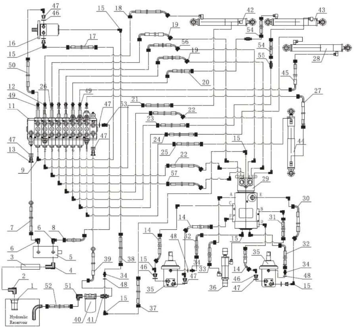
text_image
47 46 15 18 19 56 19 54 42 43 16 15 50 26 49 12 49 11 47 47 53 21 22 23 24 25 22 57 15 45 28 47 13 9 7 6 8 6 3 5 4 39 38 14 48 32 15 35 A E C B D 30 32 34 48 15 Hydraulic Reservoir 40 41 15 37 46 47 36 46 47Elenco delle parti
text_image
Exploded view diagram of a mechanical assembly with numbered components for identificationtext_image
Exploded view diagram of a mechanical assembly with numbered parts for identificationtext_image
Technical diagram of a tracked vehicle with numbered components and exploded view, likely for assembly or maintenance purposes.text_image
Technical diagram of a mechanical assembly with numbered components for identificationnatural_image
Technical line drawing of a tracked excavator with levers and motors (no text or symbols)natural_image
Technical line drawing of a tracked excavator assembly with mounting bracket and guide rails (no text or symbols)Rastrello (venduto separatamente)
natural_image
Line drawing of an excavator with tracked blade and bucket (no text or symbols)natural_image
Technical line drawing of an excavator and tracked vehicle (no text or symbols present)Pollice (venduto separatamente)
natural_image
Line drawing of an excavator with tracked base and mechanical components (no text or symbols)text_image
Technical diagram showing the assembly of an excavator with labeled components and motion arrows indicating changes.Artiglio (venduto separatamente)
natural_image
Technical line drawing of an excavator with tracked components and control arms (no text or symbols)natural_image
Technical line drawing of a tracked excavator with attached mechanical components (no text or symbols)natural_image
Line drawing of an excavator with tracked base and blade assembly (no text or symbols)natural_image
Technical line drawing of an excavator with tracked base and bucket, no text or symbols presentBaldacchino (venduto separatamente)
natural_image
Line drawing of an excavator with tracked base and attached bucket (no text or symbols)text_image
M10 x 95 x 3text_image
Diagram illustrating vehicle parking and parking rules with no restrictions on one side and a vehicle moving to the other.text_image
Technical diagram of a mechanical engine with numbered components for identification1- Silenziatore
2- CANDELA DI ACCENSIONE:
3- Soffocamento
text_image
Technical diagram of a mechanical engine with numbered components labeled 1, 2, and 3.text_image
Technical diagram of a mechanical engine with numbered components for identification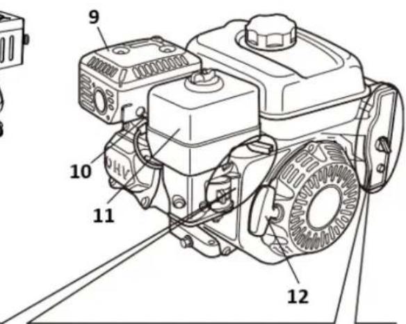
text_image
9 10 11 1213
13
10- CANDELA DI ACCENSIONE:
text_image
Technical diagram of a mechanical assembly with numbered components labeled 1, 2, and 3.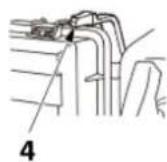
A
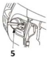
B
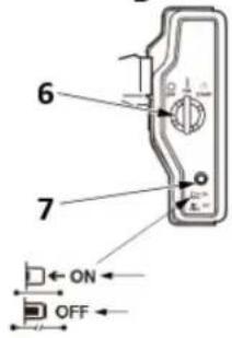
text_image
6 7 ON OFFtext_image
Technical diagram of a car door assembly with labeled parts and directional arrows indicating motion or movement.1- Lento
2- Veloce
text_image
1 2 3 4 5 START CLOSED CHoke OPEN1- Aprire
2- Leva dello starter
3- Vicino
4- Aprire
natural_image
Diagram of a hand turning a mechanical component with a tool, labeled '1' (no text or symbols on the diagram itself)text_image
Technical diagram of a mechanical component with numbered parts and directional arrows indicating motion or flow.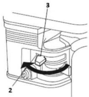
text_image
Technical diagram of a mechanical device with labeled parts 2, 3, and directional arrows indicating movement or force.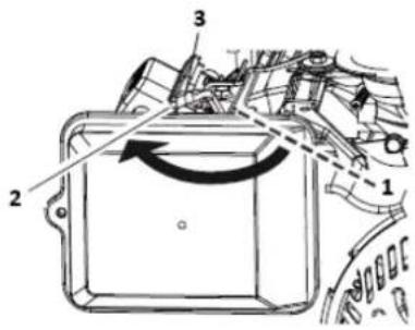
text_image
Technical diagram of a mechanical component with numbered parts and directional arrows indicating motion or flow.1- APRIRE
2- VICINO
text_image
Technical diagram of a mechanical assembly with numbered components and directional arrows indicating motion or force.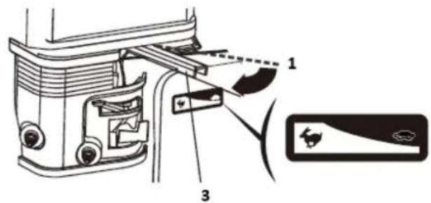
text_image
Technical diagram of a vehicle door assembly with labeled parts and component indicators1- Lento
2- Veloce
text_image
Technical diagram of a mechanical component with labeled parts and directional arrows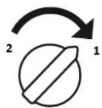
text_image
2 11- SU
2- SPENTO
natural_image
Diagram of a hand turning a mechanical component with labeled parts (no text or symbols present)text_image
Technical diagram of a mechanical component with numbered parts and an arrow indicating rotational motion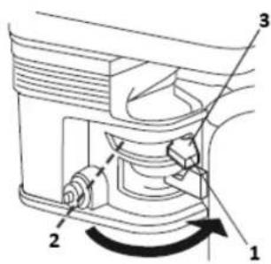
text_image
Technical diagram of a mechanical device with numbered components and directional arrows indicating motion or flow.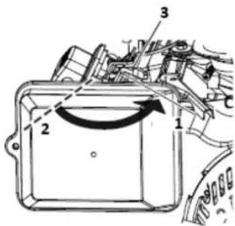
text_image
Technical diagram of a mechanical component with numbered parts and directional arrows indicating motion or movement.1- Aprire
2- Vicino
text_image
Technical diagram of a mechanical assembly with numbered components labeled 1, 2, and 3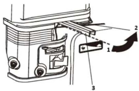
text_image
Technical diagram of a mechanical assembly with numbered components and directional arrows indicating motion or assembly.1- Veloce
2- Lento
text_image
1 2 O I 2 3 11- SU
2- SPENTO
text_image
Technical diagram of a mechanical device with numbered components and directional arrows indicating motion or rotation.1- Aprire
2- Vicino
text_image
Technical diagram of a mechanical assembly with numbered components and directional arrows indicating motion or rotation.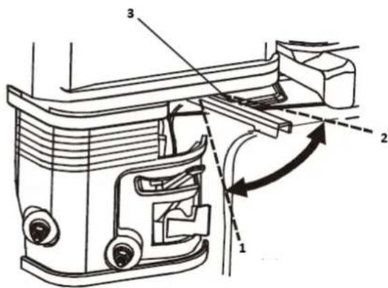
text_image
Technical diagram of a mechanical assembly with numbered components and directional arrows indicating motion or flow.1- Veloce
2- Lento
177F(E)/ TR270(E)/ TR306(E): 6,0 L
188F(E)/ TR389(E): 6,0 litri
190F(E) /192F(E)/TR420(E)/TR440(E)/TR460(E): 6,0 l
text_image
Technical diagram showing a mechanical assembly with labeled components and a hand using a tool to adjust or install a component.text_image
Technical diagram showing mechanical assembly steps with labeled parts 1, 2, and 3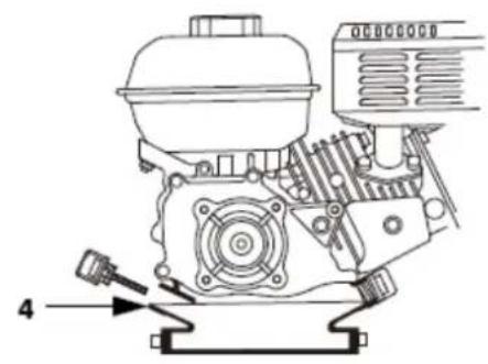
natural_image
Technical line drawing of a mechanical engine assembly with no visible text or symbolstext_image
Technical diagram showing mechanical assembly with labeled parts 1 and 2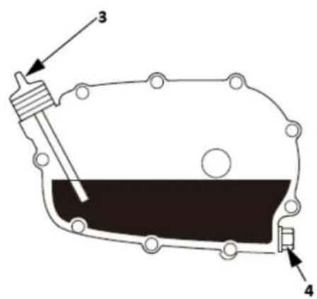
text_image
Technical diagram of a mechanical component with labeled parts 3 and 4bar
| Temperature Range | Value | | :--- | :--- | | 10W-30 | 10W-30 | | 30 | 30 | | 5W-30 | 5W-30 | The chart displays a single bar for the 10W-30 range on the x-axis, with the y-axis labeled 'A' and 'B'. The values are explicitly labeled at the top of each bar: 10W-30 = 10W, 30 = 60, and 5W-30 = -20. The scale is marked as '40°C' on the right.text_image
Technical diagram of a mechanical assembly with numbered parts, likely a valve or pump component.1-Dado ad alette
natural_image
Line drawing of two hands holding a tool, one open showing a meshed component (no text or symbols)flowchart
graph LR
    A["1 Hand washing in a bowl"] --> B["2 Downing liquid"]
    B --> C["3 Hand washing in a tray"]
    C --> D["4 Downing liquid"]
1-Pulire
text_image
Technical diagram of a mechanical assembly with numbered parts, likely a valve or pump component.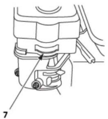
natural_image
Technical line drawing of a mechanical device with labeled parts (no text or symbols present)text_image
Diagram showing a mechanical device with labeled parts, including a piston and valve assembly.1-Cappuccio sedimentario
2-O-ring
SERVIZIO CANDELE
Candele consigliate:
Italiano: E6RTC/E6TC:152F/154F/156F/TR79/TR87/TR98
F6RTC/F6TC:160F(E)/168F(E)/168FB(E)/TR163(E)/TR196(E)170F(E)/170FB(E)
/TR212(E)/TR223(E)/172F(E)/TR236(E)/177F(E)/TR270(E)/188F(E)/190F(E)/
190FB(E)/192F(E)/194F(E)/TR389(E)/TR420(E)/TR440(E)/TR460(E)/TR479(E)
| F6RTC | F7RTC | |
| CAMPIONE | RN6YC/RN6Y | RN7YC/RN7Y |
| NGK | BPR6ES | BPR7ES |
| DENSO | W20EPR_U | W22EPR_U |
| BOSCH | WR7DC | WR5DC |

text_image
Technical diagram showing mechanical assembly with labeled parts 1 and 2, likely for industrial or automotive maintenance.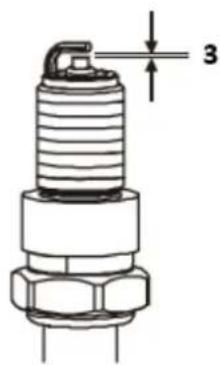
text_image
3natural_image
Technical line drawing of a vehicle engine assembly showing valve and shaft components (no text or labels)text_image
Exploded view diagram of an electrical switchgear assembly with numbered parts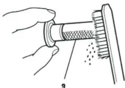
natural_image
Illustration of hands performing a mechanical tool with a meshed component and dotted lines indicating motion (no text or symbols)text_image
Technical diagram of a coffee maker with labeled parts including feeding, mixing, and cleaning stepstext_image
Technical diagram of an automotive battery assembly with labeled parts 1, 2, and 3text_image
Technical diagram of a mechanical assembly with numbered parts and exploded view, likely for assembly or maintenance instructions.text_image
Technical diagram of a mechanical assembly with labeled parts 1 and 21- PORTAFILO
text_image
Technical diagram showing mechanical assembly with numbered parts and labeled partstext_image
Technical diagram of a mechanical assembly with numbered components for identification1- VITE da 4 mm
2- PORTAFILO
3- FILO
4- ANELLO DI SICUREZZA da 5 mm