HPM-02 - Industrial machine tool MSW - Free user manual and instructions
Find the device manual for free HPM-02 MSW in PDF.

| Product type | Hydraulic punch machine |
| Model | MSW-HPM-02 |
| Maximum production capacity | 31 tonnes |
| Maximum pressure | 700 bar |
| Throat depth | 95 mm |
| Maximum thickness (steel/iron) | 3-8 mm |
| Maximum thickness (copper/aluminum) | 3-10 mm |
| Dimensions (L×W×H) | 120×220×345 mm |
| Weight | 16.35 kg |
| Power supply | Electric hydraulic unit (230 V / 400 V depending on model) |
| Main function | Hole punching in metal, plastic and wood |
| Punching type | Automatic hydraulic |
| Interchangeable tools | Punches and dies of different diameters |
| Routine maintenance | Check tool tightness every 100 holes; maintain hydraulic oil level |
| Oil change | Every 3000 operating hours (oil HLP 46) |
| Safety | Use with protective gloves and goggles; do not exceed max. plate thickness |
| Spare parts available | Punches, dies, retaining device, hydraulic hoses |
| Repairability | Easy replacement of tools and hoses |
| Warranty | 2 years (according to manufacturer's conditions) |
| Recommended use | Industry, manufacturing, construction |
Frequently Asked Questions - HPM-02 MSW
User questions about HPM-02 MSW
0 question about this device. Answer the ones you know or ask your own.
Ask a new question about this device
Download the instructions for your Industrial machine tool in PDF format for free! Find your manual HPM-02 - MSW and take your electronic device back in hand. On this page are published all the documents necessary for the use of your device. HPM-02 by MSW.
USER MANUAL HPM-02 MSW
HYDRAULIC PUNCHING MACHINE
| DE | Produktname | Hydraulische Stanzmaschine |
| EN | Product name | Hydraulic punching machine |
| PL | Nazwa produktu | Hydrauliczna maszyna dziurkująca |
| CZ | Název výrobku | Hydrauliczna maszyna dziurkująca |
| FR | Nom du produit | Poinçonneuse hydraulique |
| IT | Nome del prodotto | Punzonatrice idraulica |
| ES | Nombre del producto | Punzonadora hidráulica |
| HU | Termék neve | Hidraulikus lyukasztógép |
| DA | Produktnavn | Hydraulisk stansemaskine |
| FI | Tuotteen nimi | Hydraulinen lävistyskone |
| NL | Productnaam | Hydraulische ponsmachine |
| NO | Produktnavn | Hydraulisk stansemaskin |
| SE | Produktnamn | Hydraulisk stansmaskin |
| PT | Nome do produto | Máquina de perfuração hidráulica |
| SK | Názov produktu | Hydraulický dierovací stroj |
| BG | Име на продукта | Хидравлична щанцова машина |
| EL | Όνομα προϊόντος | Υδραυλικό μηχάνημα διάτρησης |
| HR | Naziv proizvoda | Hidraulički stroj za bušenje |
| LT | Produkto pavadinimas | Hidrauliné perforavimo mašina |
| RO | Numele produsului | Maşină de perforat hidraulic |
| SL | Ime izdelka | Hidravlični prebijalni stroj |
| DE Modell | EN Product model | PL Model produktu | CZ Model výrobku | FR Modèle | IT Modello | ES Modelo | HU Modell | DA Model | FI Tuotteen malli | NL Productmodel | NO Produktmodell | SE Produktmodell | PT Modelo do produto | SK Model | BG Модел на продукт | EL Movtělo προϊόντος | HR Model proizvoda | LT: Gaminio modelis | RO: Model de produs | SL: Model izdelka | MSW-HPM-02 | |
| DE Hersteller | EN Manufacturer | PL Producent | CZ Výrobce | FR Fabricant | IT Produttore | ES Fabricante | HU Termelő | DA Producent | FI Valmistaja | NL Producent | NO Produsent | SE Tillverkare | PT Fabricante | SK Výrobca | BG Производител | EL Κατασκευαστής | HR Proizvođač | LT Gamintojas | RO Producător | SL Proizvajalec | expondo Polska sp. z o.o. sp. k. | |
| DE Anschrift des Herstellers | EN Manufacturer Address | PL Adres producenta | CZ Adresa výrobce | FR Adresse du fabricant | IT Indirizzo del produttore | ES Dirección del fabricante | HU A gyártó címe | DA Producentens adresse | FI Valmistajan osoite | NL Adres producent | NO Produsentens adresse | SE Tillverkarens adress | PT Endereço do fabricante | SK Adresa výrobcu | BG Адрес на производителя | EL: Διεύθυνση κατασκευαστή | HR Adresa proizvođača | LT Gamintojo adresas | RO Adresa producătorului | SL Naslov proizvajalca | ul. Nowy Kisielin – Innowacyjna 7, 66-002 Zielona Góra | Poland, EU | |

natural_image
Yellow mechanical device with black handle and multiple black components, accompanied by a small inset showing a tool (no text or symbols visible)natural_image
Technical line drawings of a mechanical device with open case, internal components, and external housing (no text or symbols)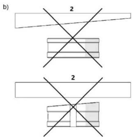

natural_image
Technical line drawing of a mechanical assembly with a rotating component and base mount (no text or symbols)This User Manual has been translated using machine translation. We have made every effort to ensure the translation is accurate, but please note that automated translations are not perfect and are not meant to replace human translators. The official version of the User Manual is in English. Any differences between the translated version and the original English are not legally binding. If you have any questions about the accuracy of the translation, please refer to the English version, which is the official reference. More language versions are available upon request via info@expondo.com.
Technical data
| Parameter description | Parameter value |
| Product name | Hydraulic punching machine |
| Model | MSW-HPM-02 |
| Capacity max output [ton] | 31 |
| Capacity max pressure [bar] | 700 |
| Throat depth [mm] | 95 |
| Maximum thickness for steel/iron [mm] | 3-8 |
| Maximum thickness for copper/aluminium [mm] | 3-10 |
| Dimensions (Width x Length x Height) [mm] | 120x220x345 |
| Weight [kg] | 16.35 |
Product overview
natural_image
Yellow industrial machine with black handle and multiple black plastic components (no visible text or symbols)The product is a tool used for creating holes or indentations in various materials, such as metal, plastic, and wood. It operates using hydraulic force to deliver precise, high-pressure punches, commonly utilized in manufacturing and construction for tasks like sheet metal fabrication, automotive parts production, and heavy-duty metalworking.
The user is liable for any damage resulting from unintended use of the product.
Operation
Unpacking
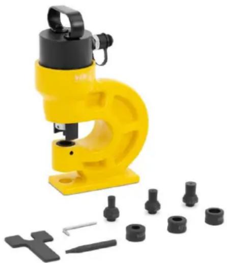
To begin, open the box and use the 5 mm hex wrench to unscrew the lock and remove the machine. Then, screw in the front handle. Next, secure the handle to the power pack in the position shown in Figure 1 using six M8x12 screws and the 5 mm hex wrench.
natural_image
Technical line drawings of a mechanical device with open case, internal components, and external housing (no text or symbols)Figure 1 Assembling the machine and the power pack after unpacking
1- M8x12 screws
Installing the punch and die
- Set the power ON/OFF switch to the position 'O'.
- Insert the nut joined with the punch into the machine (1, Figure 2).
- Screw the nut manually in the direction (2, Figure 2).
- Insert the wrench into the hole (3, Figure 2) and lock the nut by rotating the wrench in the same direction.
- If an oblong punch (4, Figure 2) is used, before locking the nut, the punch pin must snap into the socket, which will be indicated by a snap sound.
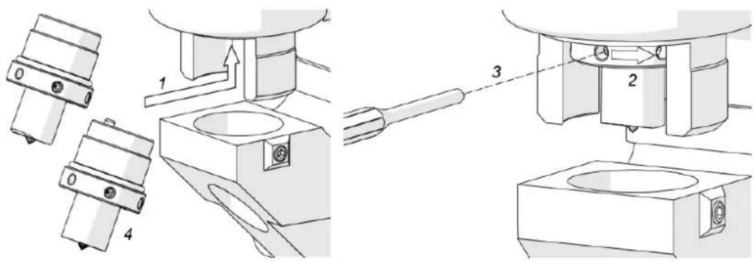
Figure 2. Installing the punch
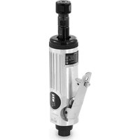
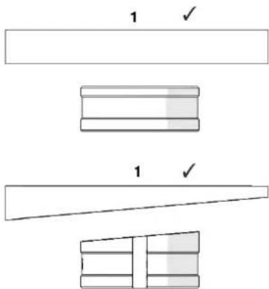
- Select a proper die for the plate to be punched:
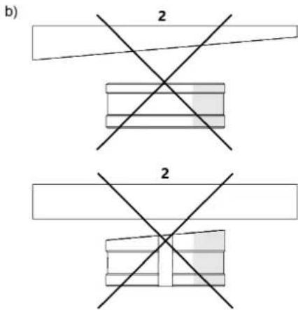
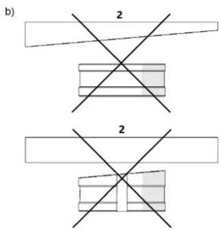
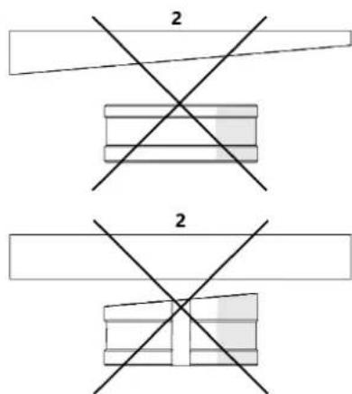
- Use dies with parallel surfaces for plates with parallel surfaces.
-
Use 5^ inclined dies for plates with one surface inclined by 5^ (Figure 3a).
-
Never use dies with parallel surfaces for plates with one surface inclined.
-
Never use inclined dies for plates with both surfaces parallel (Figure 3b).
a)
b)

Figure 3. Selecting a die for the plate used
1- Correct
2- Incorrect
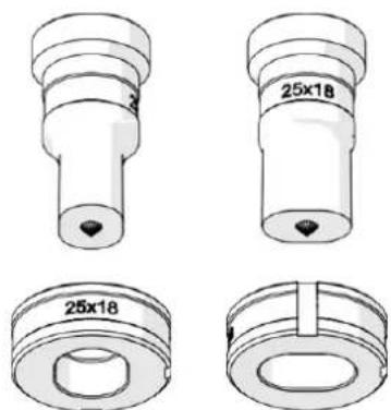
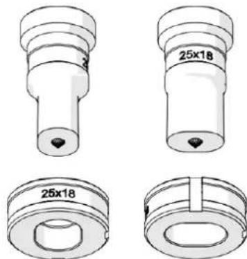
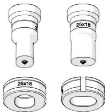
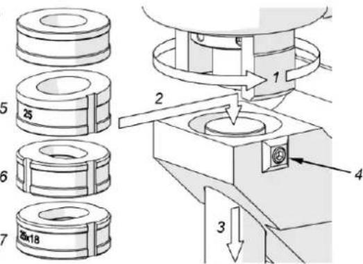
- Retract the restrainer as far as possible (1, Figure 4a).
- Rest the die onto the drift (2, Figure 4).
- Lower the drift to insert the die into the socket (3, Figure 4).
- Tighten the die with the 4 mm hex wrench (4, Figure 4).
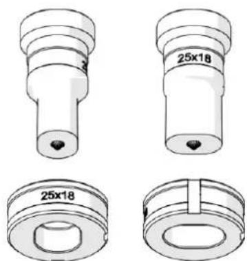
- The diameters (dimensions) of the punch and die installed must be the same.
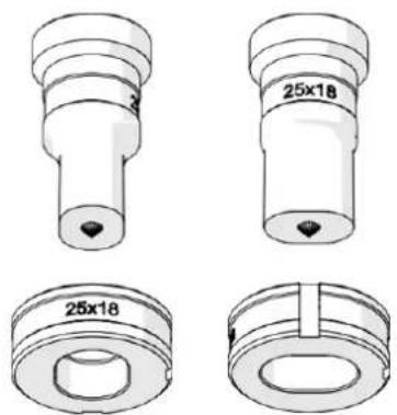
- Position inclined dies (5, Figure 4) and oblong dies (6 and 7, Figure 4) in such a way to align the groove with the set screw (4, Figure 4).
- Always install oblong dies and oblong punches in the same orientation (Figure 4b).
a)

b)

natural_image
Technical drawings of mechanical components with no visible text or symbolsFigure 4. Installing the die (a); correct orientation of the oblong punch and die (b)
Connecting the hydraulic power pack
- Connect the machine with the hydraulic power pack using the hydraulic hoses and control cable.
- Remove the caps from the hydraulic sockets of the machine.
- Use the 27 mm and 30 mm flat wrenches to firmly screw the high-pressure line into connection 1 (Figure 5).
- Plug the low-pressure line into connection (Figure 5) until it snaps into place.
-
Connect the control cable to connector 3 (Figure 5) and plug the power cord of the hydraulic power pack into an appropriate power source.
-
Every time the power pack is connected and the power ON/OFF switch is set to position 'I', the signal LED will flash every 1/2 second indicating the need to press and hold the STOP/UP button for about 3 seconds.
- This will cause the punch to retract fully if it is not already in this position.
- Use the 8 mm hex wrench to unscrew the transport cap 4 (Figure 5) of the hydraulic power pack.
- Place the oil plug in the cap's position 5 (Figure 5).
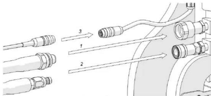

Figure 5. Connecting the machine to the hydraulic power pack
Positioning
- Hang the machine on the chain.
- Position the machine on a plate as shown in the detail from Figure 6, with the restrainer located above the plate and the punch tip placed into a center-punch mark indicating the center of the hole to be made.
- Press the machine down to the plate.
- Ensure the restrainer is rotated such that it is above the plate, but not outside the plate, to allow the entire support of the restrainer during retraction of the punch.
- Loosen the four depth stop screws using the 6 mm hex wrench.
- Adjoin the depth stop to the plate, and tighten it in this position.
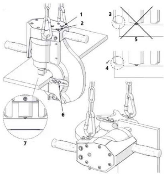
Figure 6. Positioning the machine on the plate
1- STOP/UP
2- DOWN
3- INCORRECT
4- Restrainer outside the plate
5-CORRECT
6- Depth Stop screws
7- Restrainer above the plate
Punching

CAUTION
- Add 8# or 10# Anti-wear Hydraulic Oil. The oil must be filtered through a 200# filter to remove impurities.
- The working component should be connected to a powerful pump with an internal pressure of 70 MPa.
-
Connect the pump and the working component using the coupler.
-
Secure the workpiece, close the oil valve, and repeatedly pull the handle until the work is complete, then turn off the switch.
-
Operate the machine by holding the handles with both hands. The continuous LED light indicates the machine is ready to operate.
-
Press and hold the DOWN button to move the punch toward the plate. This will be indicated by the LED flashing every 0.25 seconds.
-
When the punch reaches the plate, the automatic punching process should start, indicated by the LED flashing every 0.1 seconds.
-
After the end of the punching process, the punch will return to the initial position.
-
Punching thin plates may require the DOWN button to be held until the hole is established.
-
To interrupt the motion at any time, press the STOP/UP button. Pressing the STOP/UP button again will retract the punch.
-
If penetrating the material fails because of excessive thickness, the motion will stop. To avoid this, do not exceed the maximum plate thickness or the value of the shear strength Rm specified in the "Maximum plate thicknesses..." section.
-
After establishing the first hole, and then after every 100 holes, check whether the punch and die are tight, and re-tighten as necessary.
-
To establish a second hole, move the machine to the next center-punch mark.
-
Once the work is finished, toggle the power pack ON/OFF switch to the position 'O'.
-
Maintain a proper oil level indication on the gauge of the hydraulic power pack.
- Change oil after 3,000 operating hours. Use HLP 46 oil.
Replacing the die and punch
Set the power ON/OFF switch to the 'O' position. To remove the die, fully retract the restrainer (1, Figure 7) and use the 4 mm hex wrench to loosen set screw (2, Figure 7). Then, use the drift (3, Figure 7) to remove the die (4, Figure 7).
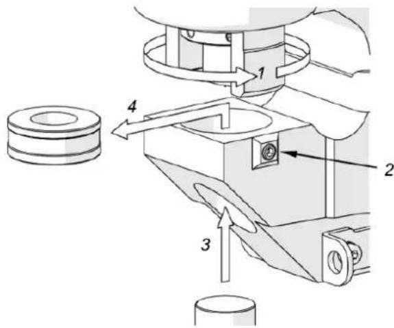
Figure 7. Dismounting the die
Mount the die as shown in Figure 4a.
To dismount the punch, insert the wrench into the hole (1, Figure 8), unscrew the nut by rotating it in direction (2, Figure 8), and remove the nut along with the punch (3, Figure 8).
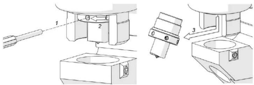
Figure 8. Dismounting the punch
Mount the punch as shown in Figure 5.
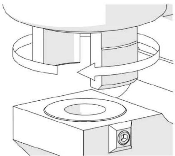
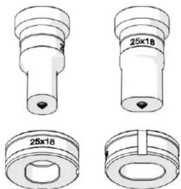
Replacing the restrainer
- Set the power ON/OFF switch to position 'O'.
- Dismount the punch as shown in Figure 8.
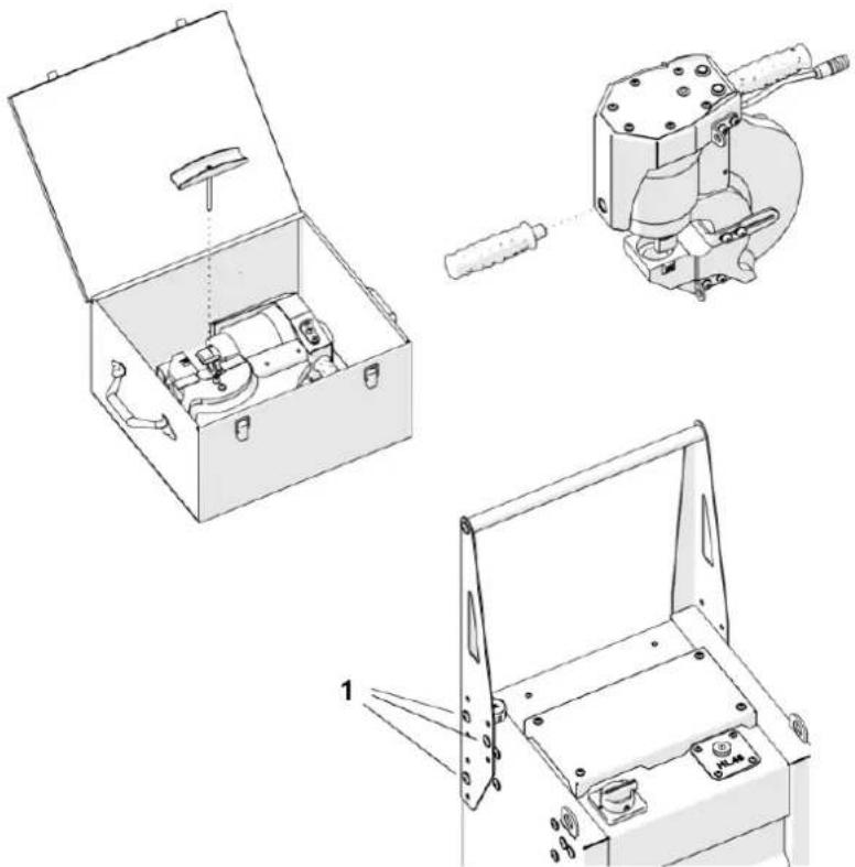
- Unscrew the restrainer by rotating it in the direction shown in Figure 9.
- Install the new restrainer by rotating it in the opposite direction.
natural_image
Technical line drawing of a mechanical assembly with a rotating component and base mount (no text or symbols)Figure 9. Removing the restrainer
Transportation
Before transporting, secure the machine to the hydraulic power pack by fastening the safety strap to lugs 1 and 2 (Figure 10). Then, attach the oil plug and transport cap as shown in the figure (3, 4, Figure 10).
Never bend the high-pressure hydraulic hose to a radius smaller than 3.2" (80 mm), as this may cause damage. If the hose is bent beyond this radius, replace it immediately.
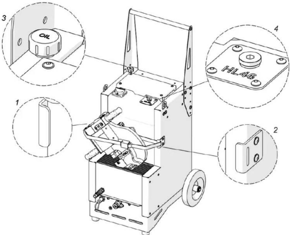
Figure 10. Transporting the Steelmax Hydraulic Punch
Troubleshooting
| Problem | Cause | Solution |
| Punch stuck in the workpiece during up movement after the hole is established. | Die with parallel surfaces used for an inclined plate, 5° inclined die used for a plate with parallel surfaces, or one surface of the plate not inclined by 5° when used with a 5° inclined die. | Use a die with parallel surfaces for a plate with parallel surfaces, while a 5° inclined die for a plate which one surface is inclined by 5°. |
| Restrainer not supported on the workpiece during the punching process. | Position the machine as described in "Positioning" section of the manual. | |
| Excessive wear of the punch or die. | Replace worn tools. | |
| Punch cracked during retraction. | Restrainer was not entirely supported on the workpiece during retraction of the punch. | Position the machine as described in "Positioning" section of the manual. |
| Punch cracked during punching the workpiece. | Excessive load during punching caused by too high thickness of the plate or too high shear strength Rm of the plate. | Choose a punch of the proper diameter for the plate thickness. Do not exceed the maximum plate thickness or the value of shear strength Rm specified in "Maximum plate thicknesses...". |
| Punch or die improperly mounted. | Mount the punch and die as described in "Mounting the punch and die" section of the manual. | |
| Punch does not retract automatically after the hole is established or while STOP/UP button is held. | High-pressure hydraulic hose not securely attached to either the machine or the power pack. | Unscrew the high-pressure hose, attach it again, and tighten its sleeve fully. |
| Hydraulic hoses not attached. | Attach the hoses as described in "Connecting the hydraulic power pack" section of the manual. | |
| Automatic punching process does not start when the punch reaches the plate. | Plate undetected because of low load when punching a thin plate. | Hold DOWNbutton until the hole is established. |
| Punch does not retract automatically after the hole is established manually by holding DOWN button. | Automatic punching process was not initialized because of low load when punching a thin plate. | Hold STOP/UPbutton to retract the punch. |

natural_image
Yellow mechanical clamp device with black components and a small inset showing a tool (no text or symbols visible)natural_image
Technical line drawings of a mechanical device with open case, internal components, and external housing (no text or symbols)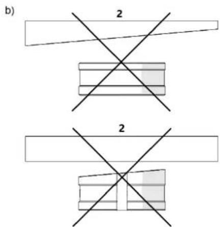
natural_image
Technical drawings of mechanical components with cross-sectional views (no text or symbols)natural_image
Technical line drawing of a mechanical assembly with a rotating component and base mount (no text or symbols)natural_image
Yellow mechanical device with black components and a small inset showing a tool or fixture (no text or symbols visible)natural_image
Technical line drawings of a mechanical device with open case, internal components, and external housing (no text or symbols)b)
natural_image
Technical drawings of mechanical components with no visible text or symbols
natural_image
Technical line drawing of a mechanical assembly with no visible text or symbolsnatural_image
Yellow mechanical device with black handle and multiple black components, accompanied by a few small tools (no text or symbols visible)natural_image
Technical line drawings of a mechanical device with open case, internal components, and close-up views (no text or symbols)Figure 2. Installation du poinçon
natural_image
Technical drawings of mechanical components with cross-sectional views (no text or symbols)
natural_image
Technical line drawing of a mechanical assembly with no visible text or symbolsnatural_image
Yellow mechanical device with black components and a few black plastic parts, no visible text or symbols.natural_image
Technical line drawings of a mechanical device with open case, internal components, and external housing (no text or symbols)
natural_image
Technical drawings of mechanical components with cross-sectional views (no text or symbols)natural_image
Technical line drawing of a mechanical assembly with no visible text or symbolsnatural_image
Yellow industrial machine with black components and various black plastic parts (no visible text or symbols)natural_image
Technical line drawings of a mechanical device with open case, internal components, and external housing (no text or symbols)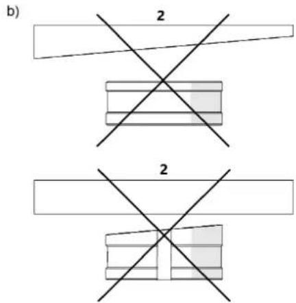
natural_image
Technical drawings of mechanical components with cross-sectional views (no text or symbols)
natural_image
Technical line drawing of a mechanical assembly with no visible text or symbolsFigura 10. Transporte de la punzadora hidráulica Steelmax
natural_image
Yellow mechanical clamp device with black components and a tool, no visible text or symbolsnatural_image
Technical line drawings of a mechanical device with open case, internal components, and external housing (no text or symbols)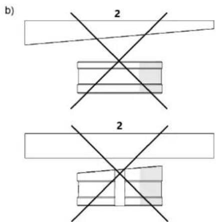
natural_image
Technical drawings of mechanical components with cross-sectional views (no text or symbols)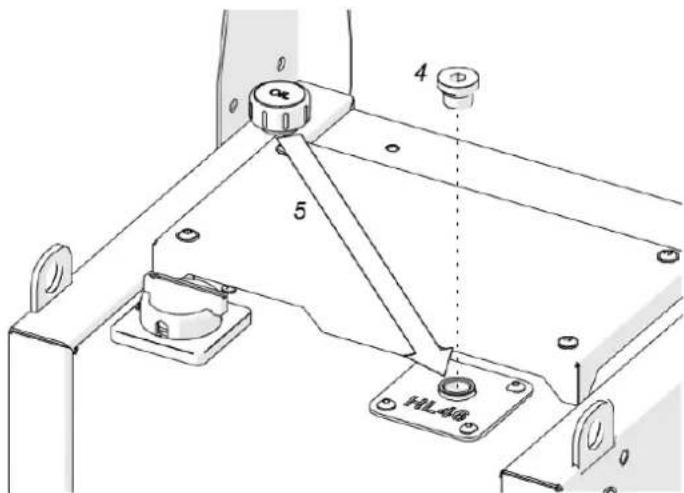
natural_image
Technical line drawing of a mechanical assembly with rotating components (no text or symbols)natural_image
Yellow mechanical clamp device with black components and a small inset showing a tool (no text or symbols visible)natural_image
Technical line drawings of a mechanical device with open case, internal components, and external housing (no text or symbols)Figur 2. Installation af stempel
b)

natural_image
Technical drawings of mechanical components with no visible text or symbols
Figur 7. Afmontering af matricen
natural_image
Technical line drawing of a mechanical assembly with a rotating component and base mount (no text or symbols)Figur 10. Transport af Steelmax' hydrauliske stempel
Problemløsning
natural_image
Yellow mechanical clamp device with black components and a small inset showing a tool (no text or symbols visible)natural_image
Technical line drawings of a mechanical device with open case, internal components, and external housing (no text or symbols)b)
natural_image
Technical drawings of mechanical components with no visible text or symbolsnatural_image
Technical line drawing of a mechanical assembly with a rotating component and base mount (no text or symbols)natural_image
Yellow industrial machine tool with black components and multiple black plastic parts (no visible text or symbols)natural_image
Technical line drawings of a mechanical device with open case, internal components, and external housing (no text or symbols)natural_image
Technical drawings of mechanical components with no visible text or symbolsFiguur 8. De pons demonteren
natural_image
Technical line drawing of a mechanical assembly with rotating components (no text or symbols)Figuur 10. Transport van de Steelmax hydraulische pons
Problemen oplossen
natural_image
Yellow mechanical clamp device with black components and a small inset showing a tool (no text or symbols visible)natural_image
Technical line drawings of a mechanical device with open case, internal components, and external housing (no text or symbols)b)
natural_image
Technical drawings of mechanical components with no visible text or symbols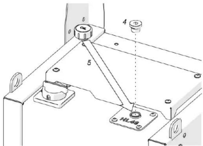
Figur 5. Koble maskinen til den hydrauliske kraftpakken
Posisjonering
Figur 6. Plassering av maskinen på platen
1- STOPP/OPP
2- NED
3- URIKTIG
4- Holder utenfor platen
5- KORREKT
6- Dybdestoppskruer
7- Begrensning over platen
Stansing

FORSIKTIGHET
natural_image
Technical line drawing of a mechanical assembly with a rotating component and base mount (no text or symbols)natural_image
Yellow mechanical device with black handle and multiple black plastic components (no visible text or symbols)natural_image
Technical line drawings of a mechanical device with open case, internal components, and external housing (no text or symbols)natural_image
Technical drawings of mechanical components with cross-sectional views (no text or symbols)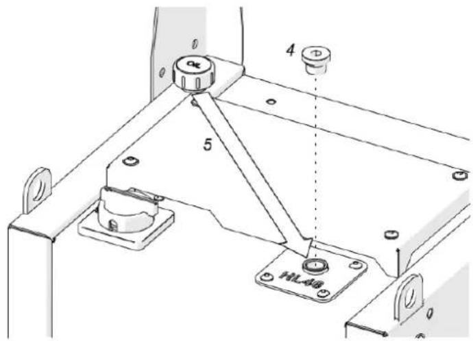
Bild 6. Placera maskinen på plattan
1- STOPP/UPP
2- NER
3- FELAKTIG
natural_image
Technical line drawing of a mechanical assembly with a rotating component and base mount (no text or symbols)Bild 10. Transportera Steelmax hydrauliska stans
Felsökning
natural_image
Yellow industrial machine tool with black components and a few black plastic parts (no text or symbols visible)natural_image
Technical line drawings of a mechanical device with open case, internal components, and external housing (no text or symbols)Figura 2. Instalando o soco
b)
natural_image
Technical drawings of mechanical components with no visible text or symbolsFigura 6. Posicionando a máquina na placa
1- PARAR/PARAR
2- ABAIXO
3- INCORRETO
Figura 7. Desmontando o dado
Figura 8. Desmontando o soco
natural_image
Technical line drawing of a mechanical assembly with no visible text or symbolsFigura 9. Removendo o contendor
Transporte
natural_image
Yellow mechanical measuring instrument with black components and exploded view (no text or symbols visible)natural_image
Technical line drawings of a mechanical device with open case, internal components, and external housing (no text or symbols)b)
natural_image
Technical drawings of mechanical components with no visible text or symbolsnatural_image
Technical line drawing of a mechanical assembly with no visible text or symbolsnatural_image
Yellow mechanical device with black handle and multiple black components, accompanied by a small tool (no text or symbols visible)natural_image
Technical line drawings of a mechanical device with open case, internal components, and external housing (no text or symbols)Фигура 2. Инсталиране на перфоратора
natural_image
Technical drawings of mechanical components with no visible text or symbols
natural_image
Technical line drawing of a mechanical assembly with rotating components (no text or symbols)natural_image
Yellow mechanical device with black handle and multiple black plastic components (no text or symbols visible)natural_image
Technical line drawings of a mechanical device with open case, internal components, and external assembly (no text or symbols)
natural_image
Technical drawings of mechanical components with cross-sectional views (no text or symbols)
natural_image
Technical line drawing of a mechanical assembly with a rotating component and base mount (no text or symbols)natural_image
Yellow mechanical clamp device with black components and a small inset showing a tool (no text or symbols visible)Proizvod je alat koji se koristi za stvaranje rupa ili udubljenja u različitim materijalima, kao što su metal, plastika i drvo. Radi koristeći hidrauličku silu za isporuku preciznih probijanja pod visokim pritiskom, koji se obično koriste u proizvodnji i građevinarstvu za zadatke kao što su proizvodnja limova, proizvodnja automobilskih dijelova i teška obrada metala.
natural_image
Technical line drawings of a mechanical device with open case, internal components, and external housing (no text or symbols)Slika 2. Ugradnja bušilice
-
Odaberite odgovarajuću matricu za ploču koja se buši:
-
Koristite kalupe s paralelnim površinama za ploče s paralelnim površinama.
-
Koristite 5° nagnute matrice za ploče s jednom površinom nagnutom za 5° (Slika 3a).
-
Nikada nemojte koristiti kalupe s paralelnim površinama za ploče s jednom nagnutom površinom.
-
Nikada nemojte koristiti nagnute matrice za ploče s obje površine paralelne (Slika 3b).
a)

b)
Slika 3. Odabir matrice za korištenu ploču
1- Točno
2- Netočno
- Uvucite držač što je više moguće (1, slika 4a).
- Naslonite matricu na ispust (2, slika 4).
- Spustite izbočinu kako biste umetnuli matricu u utičnicu (3, slika 4).
- Zategnite matricu imbus ključem od 4 mm (4, slika 4).
- Promjeri (dimenzije) ugrađenog probojca i matrice moraju biti isti.
- Postavite nagnute matrice (5, slika 4) i duguljaste matrice (6 i 7, slika 4) na takav način da poravnate utor s vijkom za podešavanje (4, slika 4).
- Uvijek postavljajte duguljaste matrice i duguljaste probojce u istom smjeru (Slika 4b).
a)
b)

natural_image
Technical drawings of mechanical components with no visible text or symbolsSlika 4. Ugradnja matrice (a); ispravna orijentacija duguljastog izbojca i matrice (b)
Spajanje hidrauličkog agregata

Slika 5. Spajanje stroja na hidraulički agregat
Pozicioniranje
Slika 6. Postavljanje stroja na ploču
1- STOP/GORE
2- DOLJE
3- NETOČNO
natural_image
Technical line drawing of a mechanical assembly with a rotating component and base mount (no text or symbols)Slika 10. Prijevoz Steelmax hidrauličkog probijača
Rješ avanje problema
natural_image
Yellow industrial machine tool with black components and multiple black plastic parts (no visible text or symbols)natural_image
Technical line drawings of a mechanical device with open case, internal components, and external housing (no text or symbols)b)
natural_image
Technical drawings of mechanical components with cross-sectional views (no text or symbols)
5 pav. Mašinos prijungimas prie hidraulinio maitinimo bloko
Padèties nustatymas
7 pav. Nuimamas štampas
natural_image
Technical line drawing of a mechanical assembly with a rotating component and base mount (no text or symbols)10 pav. Steelmax hidraulinio perforatoriaus transportavimas
Trikčių Š alinimas
natural_image
Yellow mechanical clamp device with black components and multiple black plastic parts (no text or symbols visible)natural_image
Technical line drawings of a mechanical device with open case, internal components, and external housing (no text or symbols)b)

natural_image
Technical drawings of mechanical components with no visible text or symbolsFigura 7. Demontarea matritei
natural_image
Technical line drawing of a mechanical assembly with no visible text or symbolsnatural_image
Yellow mechanical clamp device with black components and multiple black plastic parts (no text or symbols visible)natural_image
Technical line drawings of a mechanical device with open case, internal components, and external housing (no text or symbols)b)

natural_image
Technical drawings of mechanical components with no visible text or symbols
natural_image
Technical line drawing of a mechanical assembly with a rotating component and base mount (no text or symbols)For the disposal of the device please consider and act according to the national and local rules and regulations.
CONTACT
expondo Polska sp. z o.o. sp. k.