HCP5000 - Pressure washer SCHEPPACH - Free user manual and instructions
Find the device manual for free HCP5000 SCHEPPACH in PDF.

| Product type | Thermal high-pressure cleaner |
| Brand | Scheppach |
| Model | HCP5000 |
| Engine | 4-stroke, 212 cc, 4.3 kW (5.9 HP) |
| Fuel | Unleaded petrol (max 10% ethanol) |
| Operating pressure | 221 bar (max 241 bar) |
| Max flow rate | 9.5 L/min |
| Fuel tank | 3.6 L |
| Engine oil | 0.6 L (SAE 10W30) |
| Weight | 25.5 kg |
| Water connection | G 3/4 (EU), 12 mm hose |
| Max water temperature | 40 °C |
| Nozzles included | 40° (white), 25° (green), 0° (red), low pressure (black) |
| Safety | Pressure relief valve, thermal valve, automatic oil shutdown |
| Sound level | LpA 90 dB, LWA 105 dB |
| Wear parts | Spark plug, HP hose, lance, nozzles, air filter |
| Maintenance | Oil change every 50h, clean air filter, check spark plug |
| Usage | Outdoor, cleaning vehicles, facades, terraces |
Frequently Asked Questions - HCP5000 SCHEPPACH
User questions about HCP5000 SCHEPPACH
0 question about this device. Answer the ones you know or ask your own.
Ask a new question about this device
Download the instructions for your Pressure washer in PDF format for free! Find your manual HCP5000 - SCHEPPACH and take your electronic device back in hand. On this page are published all the documents necessary for the use of your device. HCP5000 by SCHEPPACH.
USER MANUAL HCP5000 SCHEPPACH
natural_image
Technical line drawing of a power plant with pump, fan, and motor (no text or symbols)
Made in P.R.C.
HCP5000 / HCP3000
| DE | Benzin-HochdruckreinigerOriginalbetriebsanleitung | 5 |
| GB | Petrol high-pressure cleanerTranslation of original instruction manual | 25 |
| FR | Nettoyeur haute pression thermiqueTraduction des instructions d'origine | 42 |
| IT | Idropulitrice a benzinaLa traduzione dal manuale di istruzioni originale | 61 |
| NL | Benzine hogedrukreinigerVertaling van de originele gebruikshandleiding | 80 |
| ES | Limpiador de alta presión de gasolinaTraducción del manual de instrucciones original | 98 |
| PT | Limpador de alta pressão a gasolinaTradução do manual de operação original | 117 |
| CZ | Benzínový vysokotlaký čističPřeklad originálního návodu k obsluze | 136 |
| SK | Benzínový vysokotlakový čističPreklad originálneho návodu na obsluhu | 153 |
| HU | Benzines nagynyomású mosóEredeti használati utasítás fordítása | 170 |
| PL | Benzynowa myjka wysokociśnieniowaTłumaczenie oryginainej instrukcji obsługi | 188 |
| HR | Benzinski visokotlačni čistačPrijevod originalnog priručnika za uporabu | 207 |
| SI | Bencinski visokotlačni čistilnikPrevod originalnih navodil za uporabo | 224 |
| EE | bensiini-kõrgsurvepesurOriginaalkäitusjuhendi tõlge | 241 |
| LT | Benzininis didelio slėgio valymo įrenginysOriginalios naudojimo instrukcijos vertimas | 258 |
| LV | Benzīna spiediena ūdens strūklastīrīšanas aparātsOriginālās lietošanas instrukcijas tulkojums | 275 |
| SE | Bensindriven högtryckstvättÖversättning av original-bruksanvisning | 292 |
| FI | bensiinikäyttöinen korkeapainepesuriKäännös alkuperäisestä käyttöohjeesta | 309 |
| DK | Benzindrevet højtryksrenserOversættelse fra den oprindelige betjeningsvejledning | 326 |
| NO | Bensindrevet høytrykksspylerOversettelse av den originale brukerveiledningen | 343 |
| BG | Бензинова машина за почистване свисоко наляганеПревод на оригиналното ръководство заексплоатация | 360 |
| GR | Βενζινοκίνητη μηχανή καθαρισμού υπόυψηλή πίεσηΜετάφραση του πρωτοτύπου των οδηγιών χρήσης | 379 |
| RO | Dispozitiv de curățare de înaltă presiunepe benzinăTraducere din manualul de exploatare original | 399 |
| RS | Benzinski čistač pod visokim pritiskomPrevod originalnog uputstva za upotrebu | 417 |
| TR | Benzinli yüksek basınçlı temizleyiciOrijinal kullanım talimatı çevirisi | 434 |
1
2
7
4
6

Inhaltsverzeichnis:
Seite:
Günzburger Straße 69
D-89335 Ichenhausen
Verehrter Kunde,
Homepage: https://www.scheppach.com/de/service
Table of contents: Page:
- Explanation of the symbols on the device.... 26
- Introduction....28
- Device description (Fig. 1-14)....28
- Scope of delivery 28
- Proper use 29
- Safety instructions 29
- Technical data....33
- Unpacking 33
- Layout 34
- Before commissioning 34
- Operation 35
- Transport....37
- Cleaning 38
- Maintenance 38
- Storage 39
- Disposal and recycling....40
- Troubleshooting 40
- Declaration of conformity 453
1. Explanation of the symbols on the device
Symbols are used in this manual to draw your attention to potential hazards. The safety symbols and the accompanying explanations must be fully understood. The warnings themselves will not rectify a hazard and cannot replace proper accident prevention measures.
 | This symbol is intended to indicate possible dangers. Follow all safety instructions that follow this symbol to avoid possible injury or death. |
 | If the instructions in the manual are not read and followed, there is a danger of injury or even death, as well as damage to property. |
 | Running engines emit carbon monoxide, an odourless, colourless, poisonous gas. Inhalation of carbon monoxide can cause nausea, fainting or death. DO NOT run indoors, even if the windows and doors are open. |
 | Petrol and its vapours are flammable and explosive. Switch off the engine and let it cool down for at least 2 minutes before refilling. |
 | Fire, naked flames and smoking prohibited! |
 | Attention: Danger of slipping on damp surfaces. |
 | Attention: Hot surface. Danger of burning! |
 | Wear safety shoes! |
 | Danger of eye injuries. Water jet can propel objects. Always wear safety goggles with side shields. |
 | Risk of electric shock! Never spray water on electrical power sources. |
 | Specification of the sound power level L_WA in dB |
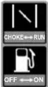 | Activate “Choke” position (only when the engine is cold).Activate “Run” position when the engine is sufficiently warm. |
 | Engine delivered without oil: (10W30)Fill the engine with the exact amount of oil according to the scope of delivery.Always check the oil level of the engine before starting.Read the operating manual before use. |
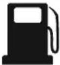 | Fill the tank with fresh, clean petrol. Do not mix oil and fuel.Do not use fuel with more than 10% ethanol content. |
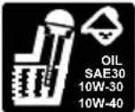 | Fill oil / check oil levelDo not operate the device if there is no oil visible in the oil tank. |
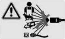 | High-pressure jets can be dangerous when used improperly. The jet must not be directed towards any persons, animals, active electrical equipment or the device itself. |
 | Warning: Device is not suitable for connection to the drinking water supply sys-tem. |
 | The product complies with the applicable European directives. |
 | The product complies with the applicable Serbian directives. |
2. Introduction
Manufacturer:
Scheppach GmbH
Günzburger Straße 69
D-89335 Ichenhausen
Dear Customer,
we wish you much pleasure and success in working with your new device.
Note:
In accordance with the applicable product liability laws, the manufacturer of this device assumes no liability for damage to the device or caused by the device arising from:
- Improper handling,
- Failure to comply with the operating manual,
• Repairs carried out by third parties, unauthorised specialists,
• Installing and replacing non-original spare parts,
• Application other than specified.
Note:
The operating manual is part of this product. It includes important instructions for the safe, proper and economic operation of the product, for avoiding danger, for minimising repair costs and downtimes and for increasing the reliability and extending the service life of the product. In addition to the safety instructions in this operating manual, you must also observe the regulations applicable to the operation of the product in your country.
Familiarise yourself with all operating and safety instructions before using the product. Only operate the product as described and for the specified areas of application. Keep the operating manual in a good place and hand over all documents when passing the product on to third parties.
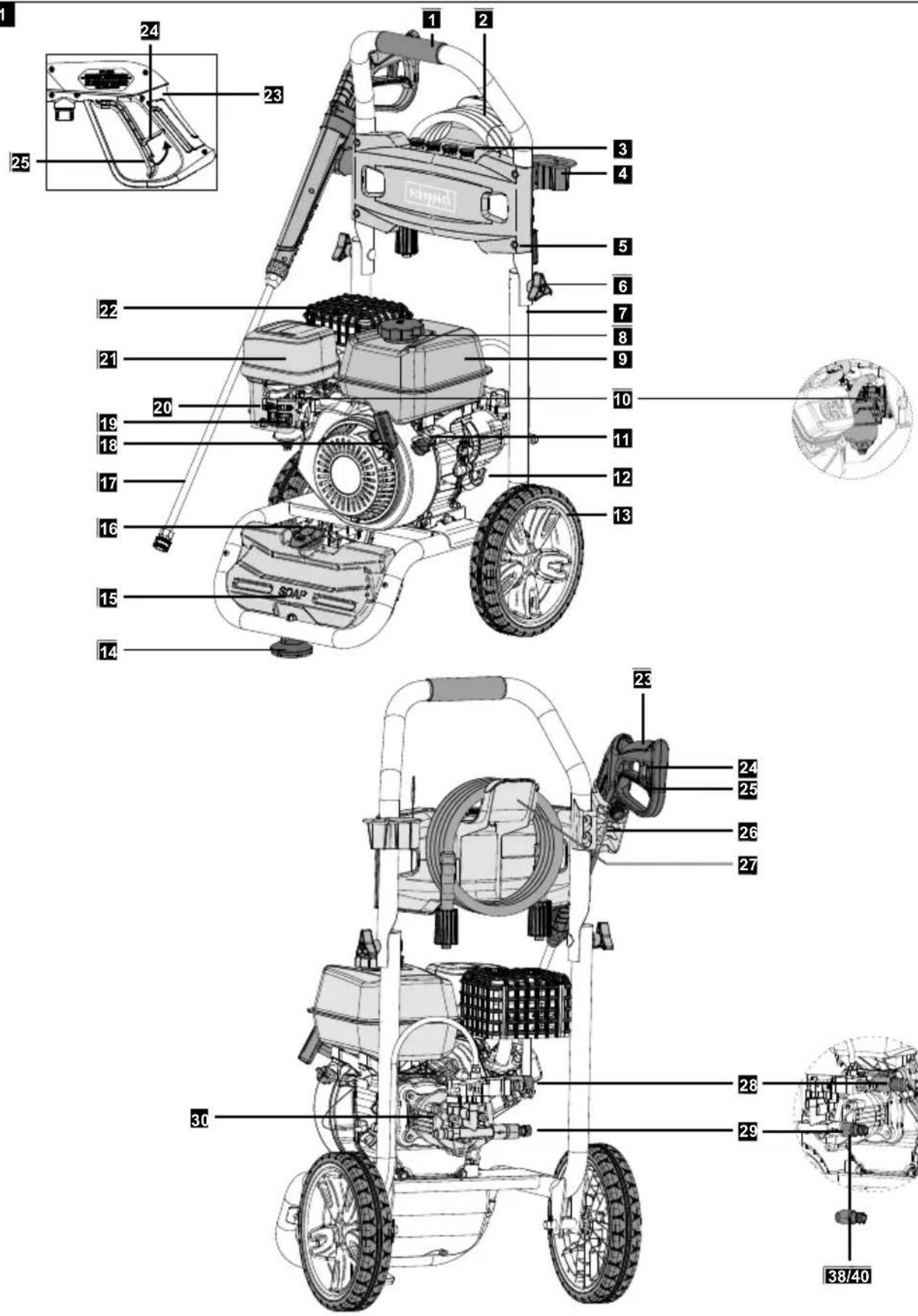
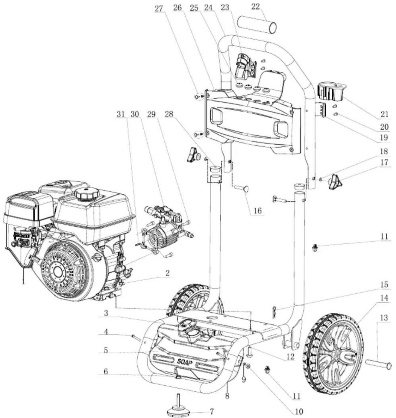
3. Device description (Fig. 1-14)
- Bow-type handle
- High-pressure hose
- Nozzles (red, green, white, black)
- Transport bracket
- Fixing plug
5.1 Sleeve - Star grip screws
6.1 Star grip screw screws - Tubular frame
-
Tank cover, incl. filter insert
-
Fuel tank
- Carburettor
- On/off switch
- Oil inlet/dipstick
12.1 Oil dipstick - Wheel
- Rubber foot
- Cleaning agent tank
- Filler cap for cleaning agent tank
- Spraying lance
- Pull starter
- Fuel valve
- Choke lever
- Air filter
- Silencer
- Hand spray gun
- Trigger lock
- Trigger
- Spray gun holder
- Hose holder
- Water outlet
- Water inlet
- High-pressure pump
- Spark plug/Spark plug connector
- Axle
- Spring split pin
- Nozzle cleaning needle
- Spark plug wrench
- Filling hose with funnel
- Quick connector
- Hose connection adapter
- Oil drain screw
- Inlet screen
- Petrol drain plug
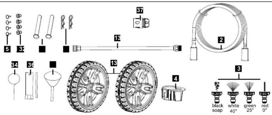
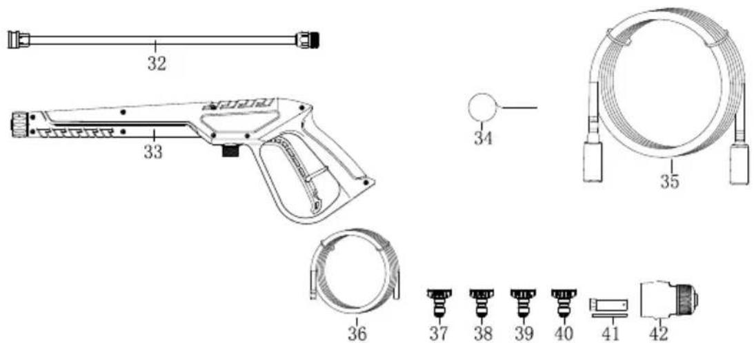
4. Scope of delivery
- Wheels (13)
- Axle (32)
- Spring split pin (33)
• High-pressure hose (2) - Hand spray gun (23)
- Spraying lance (17)
• High pressure nozzles (red, green, white) (3) - Low pressure nozzle / cleaning nozzle (black) (3)
• Transport bracket (4)
• Filling hose with funnel (36) - Nozzle cleaning needle (34)
- Spark plug wrench (35)
- Quick connector (37)
-
Hose connection adapter (38)
-
Assembly material
- Screwdriver
- Operating manual
5. Properuse
This device is intended for cleaning:
Machines, vehicles, structures, tools, facades, terraces, gardening tools, etc.
- for cleaning with the low-pressure jet and cleaning agent (e.g. cleaning of machines, vehicles, structures, tools)
- for cleaning with a high-pressure jet without cleaning agent (e.g. cleaning facades, terraces, garden tools)
The machine may only be used for its intended purpose. Any use beyond this is improper. The user/operator, not the manufacturer, is responsible for damages or injuries of any type resulting from this.
An element of the intended use is also the observance of the safety instructions, as well as the assembly instructions and operating information in the operating manual.
Persons who operate and maintain the machine must be familiar with this operating manual and must be informed about potential dangers.
The liability of the manufacturer and resulting damages are excluded in the event of modifications of the machine.
Please note that our equipment was not designed with the intention of use for commercial or industrial purposes. We assume no guarantee if the device is used in commercial or industrial applications, or for equivalent work.
6. Safety instructions
6.1 Danger levels
ATTENTION
Note on a potentially dangerous situation that can lead to property damage.
CAUTION
Note on a potentially dangerous situation that can lead to minor injuries.
⚠ WARNING
Information on a potentially dangerous situation that can lead to severe personal injury or death.
⚠️ DANGER
Information on an imminent danger that will lead to severe personal injury or death.
6.2 General safety instructions
IMPORTANT!
Before using your device for the first time, read these safety instructions and act accordingly. Store these safety instructions for later use or for subsequent owners.
- Before start-up, read the operating manual for your device and pay particular attention to the safety instructions.
- Warning and information labels attached to the device provide important information for safe operation.
- In addition to the information in the operating manual, the general safety and accident prevention regulations of the legislature must be followed.
- Observe the relevant national regulations of the legislator for liquid emitters.
- Observe the relevant national regulations of the legislator for accident prevention. Liquid emitters must be tested regularly and the result of the test must be recorded in writing.
The machines must not be used by children. Children should be supervised in order to ensure that they do not play with the device.
This machine can be used by persons with reduced physical, sensory or mental capabilities or with a lack of experience or knowledge, if they are supervised or if they have been trained in the safe use of the machine and understand the resultant hazards.
⚠ WARNING
This machine is designed to use the cleaning agents supplied or recommended by the manufacturer. The use of other cleaning agents or chemicals may affect the safety of the machine.
⚠ WARNING
High-pressure jets can be dangerous when used improperly. The jet must not be directed towards any persons, pets, active electrical equipment or the machine itself.
⚠ WARNING
Do not use this machine within range of other people unless they are wearing protective clothing.
⚠ WARNING
Do not direct the jet at yourself or others to clean clothing or footwear.
⚠ WARNING
Risk of explosion: Do not spray flammable liquids.
⚠ WARNING
High-pressure cleaners shall not be operated by children or untrained persons.
WARNING
High-pressure hoses, fixtures and couplings are important for machine safety. Only use high-pressure hoses, fixtures and couplings recommended by the manufacturer.
⚠ WARNING
To ensure machine safety, only use original spare parts from the manufacturer or spare parts approved by the manufacturer.
WARNING
Water that has flowed through the backflow prevention device is considered non-potable.
⚠ WARNING
Do not use the machine if a connection cable or important parts of the machine are damaged, e.g. safety devices, high-pressure hoses, spray gun.
⚠ WARNING
Machines powered by an internal combustion engine must not be used indoors without adequate ventilation systems approved by the relevant national health and safety authorities.
⚠ WARNING
Make sure that there are no exhaust emissions near air intakes.
6.3 Water connection
DANGER
- The high-pressure hose must not be damaged. A damaged high-pressure hose must be replaced immediately. Only hoses and connections recommended by the manufacturer may be used.
For the order no., please refer to the operating manual.
- The screw connection of all connection hoses must be tight.
ATTENTION
- Observe the regulations of your water supply company.
6.4 Operation
⚠️ DANGER
- The device with the working equipment must be checked for proper condition and operational safety before use. Do not use the device if a connection cable or important parts of the device are damaged, e.g. safety devices, high-pressure hoses, hand spray guns.
- Never inject liquids containing solvents or undiluted acids and solvents! These include, for example, petrol, paint thinner or heating oil. The spray mist is highly flammable, explosive and poisonous. Do not use acetone, undiluted acids and solvents as they can damage the materials used on the device.
- When using the device in danger zones (e.g. petrol stations), the relevant safety regulations must be observed. Do not operate the device in explosive environments.
- All live parts in the work area must be protected from water jets.
- The trigger of the hand spray gun must not be jammed during operation.
ATTENTION
- Do not use acetone, undiluted acids or solvents as they corrode the materials used on the device.
• The device must have a level, stable base.
- Do not operate the device at temperatures below 5^ .
WARNING
- When using cleaning agents, the safety data sheet of the cleaning agent manufacturer must be observed, especially the instructions on personal protective equipment.
- Only cleaning agents approved by the device manufacturer may be used. This device has been developed for the use of cleaning agents that are supplied or recommended by the manufacturer. The use of cleaning agents or chemicals may affect the safety of the device.
- Keep cleaning agents out of the reach of children.
- Do not open the cover while the device is in operation.
- In case of longer breaks in operation, switch off the device at the main switch / device switch.
⚠ WARNING
- Asbestos-containing materials and other materials containing substances hazardous to health must not be sprayed off.
- Before cleaning, a risk assessment of the surfaces to be cleaned must be carried out to identify health and safety requirements. The necessary protective measures must be taken accordingly.
- With short spraying lances there is a danger of injury as a hand may accidentally come into contact with the high-pressure jet. If the spraying lance used is shorter than 75 cm, do not use a spot spraying nozzle or rotor nozzle.
ATTENTION
- Vehicle tyres/tyre valves may only be cleaned with a minimum spraying distance of 30 cm. Otherwise the vehicle tyre/tyre valve may be damaged by the high-pressure jet. The first sign of damage is the discolouration of the tyre. Damaged vehicle tyres are a source of danger.
CAUTION
- If the operating manual of the unit (technical data) specifies a sound pressure above 80 dB, wear hearing protection.
- Wear suitable protective clothing and safety goggles to protect against splashing water or dirt.
- The recommended cleaning agents must not be used undiluted. The products are safe to operate as they do not contain any environmentally harmful substances. In case of contact of cleaning agent with eyes, immediately rinse thoroughly with plenty of water and consult a doctor immediately if swallowed.
- Allow the hoses to cool down after hot water operation or operate the device briefly in cold water mode.
6.4.1 For units with a hand-arm vibration value >2.5 m/s ^2 (see technical data)
⚠️ DANGER
- Prolonged use of the device may lead to vibration-induced circulatory problems in the hands. A generally valid duration for use cannot be determined because it depends on several influencing factors:
- Personal predisposition to poor circulation (often cold fingers, finger tingling).
- Low ambient temperature. Wear warm gloves to protect your hands.
- Tight grasping worsens the blood circulation.
- Uninterrupted operation is worse than operation interrupted by breaks.
- In case of regular, long-term use of the device and repeated occurrence of corresponding signs (for example, finger tingling, cold fingers), we recommend a medical examination.
6.5 Operation
⚠ WARNING
- For petrol or oil-powered machines, it is important to provide adequate ventilation and ensure that exhaust gases are properly discharged.
⚠️ DANGER
- The operator must use the device as intended. It must take the local conditions into account and pay attention to third parties, especially children, when working with the device.
- The device must never be left unattended while it is in operation.
- The device may only be used by persons who have been instructed in its handling or who have demonstrated their ability to operate it and have been expressly instructed to use it. The device must not be operated by children or untrained persons.
• Always wear suitable gloves when working on the device. - The water jet coming out of the spraying lance creates a recoil force. Due to the angled spraying lance, a force acts upwards. Hold the gun and spraying lance firmly.
- When using angled spraying equipment, the recoil forces and twisting forces may change.
⚠ WARNING
- Aerosols can develop when using high-pressure cleaners. Inhaling aerosols can cause damage to your health. Respiratory protection masks of class FFP2 or higher are suitable for protection against aqueous aerosols.
6.6 Transport
⚠️ DANGER
- When transporting the device, the engine must be shut down, the spark plug connector removed and the device securely fastened.
6.7 Maintenance
⚠️ DANGER
- Before cleaning and servicing the device and replacing parts, switch off the device.
- Depressurise the high-pressure system before working on the device and accessories.
• The spark plug connector must be removed! - Repairs may only be carried out by approved service centres or by specialists in this field who are familiar with all relevant safety regulations.
6.8 Accessories and spare parts
⚠️ DANGER
• To avoid hazards, repairs and the installation of spare parts may only be carried out by authorised customer service.
- Only accessories and spare parts approved by the manufacturer may be used. Original accessories and original spare parts provide the guarantee that the device can be operated safely and without malfunctions.
6.9 Hot water and petrol engine devices
⚠️ DANGER
- Only the fuel specified in the operating manual may be used. There is a risk of explosion with unsuitable fuels.
- When refuelling devices with petrol engines, make sure that no fuel gets onto hot surfaces.
- Please always observe the special safety instructions in the operating manual for devices with petrol engines.
- When operating the device indoors, ensure that there is sufficient ventilation and that the exhaust gases are discharged. (Danger of poisoning)
• The flue opening must not be closed.
WARNING
- Danger of burning! Do not bend over or touch the flue opening.
6.10 Handling fuel
⚠️ DANGER
- Do not operate the high-pressure cleaner if fuel has been spilled, move the device to another location and avoid any spark formation.
- Do not store, spill or use fuel near open flames or equipment such as stoves, boilers, water heaters, etc. that have a pilot light or produce sparks.
-
Keep highly flammable objects and substances away from the silencer (at least 2 m).
-
Do not operate the engine without the silencer and check it regularly, clean it and replace it if necessary.
- Do not use the engine on wooded, bushy or grassy terrain without the exhaust pipe being fitted with a spark arrester.
- Except when making adjustments, do not run the engine with the air filter removed or without the cover over the intake manifold.
- Do not make any adjustments to governor springs, governor rods or other parts that may cause an increase in engine speed.
- Danger of burning! Do not touch hot silencers, cylinders or cooling fins.
- Never bring hands and feet close to moving or rotating parts.
- Danger of poisoning! Device must not be operated in closed rooms.
- Do not use unsuitable fuels as they can be dangerous.
6.11 Safety devices
Safety devices serve to protect the user and must not be overridden or converted.
6.11.1 Overpressure valve
- When the hand spray gun is closed, the pressure relief valve opens and the high-pressure pump returns the water to the pump suction side. This prevents the permitted working pressure from being exceeded.
- The pressure relief valve is set and sealed at the factory. Adjustments can only be made by the customer service.
6.11.2 Thermal valve
- The thermal valve protects the high-pressure pump against non-permitted heating in circuit operation when the hand spray gun is closed.
- The thermal valve opens when the water temperature exceeds 55 - 60°C and discharges the hot water to the outside.
6.12 Residual risks
CAUTION
Despite intended use, non-obvious residual risks cannot be completely excluded.
• Injuries due to slipping on sewage.
- Injuries or material damage caused by the high-pressure water jet.
7. Technical data
Motor
| Type DHP212 | |
| Displacement 212 cm3 | |
| Rated output at 4.3 (5.9) kW (hp) | |
| Nominal speed 3600 rpm | |
| Fuel tank | 3.6 l |
| Fuel | Petrol, unleaded |
| Oil quantity - engine | 0.6 l |
| Oil type - engine | SAE10W30 |
| Spark plug | F7RTC |
| Weight | 25.5 kg |
| CO2 output | 933.51 g/kWh |
| Water connection | |
| Hose diameter | 12 mm |
| Max. supply temperature | 40°C |
| Max. supply pressure | 0.5 (5) MPa (bar) |
| Pump | |
| Working pressure | 22.1 (221) MPa (bar) |
| Max. working pressure | 24.1 (241) MPa (bar) |
| Max. flow rate | 9.5 l/min |
| Thermal valve opening temperature | 55 - 60 °C |
| Input connection | G 3/4 (EU) |
| Output connection | M22x1.5 |
| Cleaning agents | Only use cleaning agents approved for high-pressure cleaners. |
Noise emission
Measured value for noise determined according to EN 60335-2-79. The A-weighted noise level is typically:
Sound pressure level L_pA .....90 dB
Uncertainty K_pA 3 dB
Sound power level L_WA 105 dB
Uncertainty K_WA 3 dB
Wear hearing protection to avoid hearing damage!
Vibration emission values (vector sum of three directions) determined per EN 60335-2-79:
Hand spray gun handle
Vibration value 1.62 m/s²
Hand spray gun, centre
Vibration value 2.27 m/s ^4
Uncertainty K 0.85 m/s ^4
Note:
The vibration level specified in this instruction has been measured based on a measurement procedure standardised in EN 60335-2-79 and can be used for unit comparison. The specified vibration emission value can also be used for an initial estimation of the exposure.
⚠ WARNING
- The vibration level will vary depending on the use and may in some cases be higher than the value specified in these instructions. The vibration load could be underestimated if the device is regularly used in such a way. For an accurate estimation of the vibration exposure during a given working period, the times when the device is switched off or running but not actually in use should also be taken into account.
- This can significantly reduce the vibration load over the entire working period.
8. Unpacking
- Open the packaging and carefully remove the device.
- Remove the packaging material, as well as the packaging and transport safety devices (if present).
- Check whether the scope of delivery is complete.
- Check the device and accessory parts for transport damage. In the event of complaints the carrier must be informed immediately. Later claims will not be recognised.
- If possible, keep the packaging until the expiry of the warranty period.
- Familiarise yourself with the device by means of the operating instructions before using for the first time.
- With accessories as well as wearing parts and replacement parts use only original parts. Spare parts can be obtained from your specialist dealer.
- When ordering please provide our article number as well as type and year of manufacture for your device.
⚠️ DANGER
The device and the packaging are not children's toys! Do not let children play with plastic bags, films or small parts! There is a danger of choking or suffocating!
⚠ WARNING
- During unpacking, transport and storage, bear in mind the high dead weight of the machine. These activities should be carried out by two people.
- Make sure the device is level on a flat surface during unpacking, installation and storage, operation, testing, maintenance and when not in use.
9. Layout
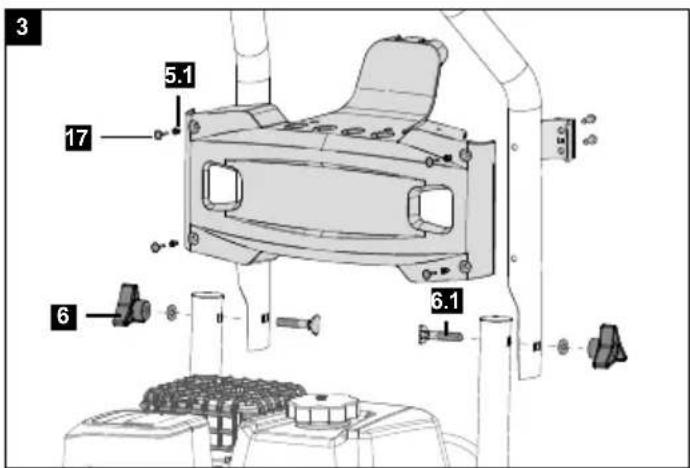
9.1 Installing the bow-type handle (Fig. 3)
- Fold the bow-type handle (1) onto the base frame of the device.
- Tighten the star grip screw (6) using the existing screws (6.1).
9.2 Fitting the spraying nozzle unit (Fig. 1)
- Position the spraying nozzle unit so that the holes provided for it are on top of each other.
- Now fix the unit with four sleeves (5.1) and the fixing plugs (5).
- To do this, first press the sleeves into the holes provided and then secure them with the fixing plugs (5).
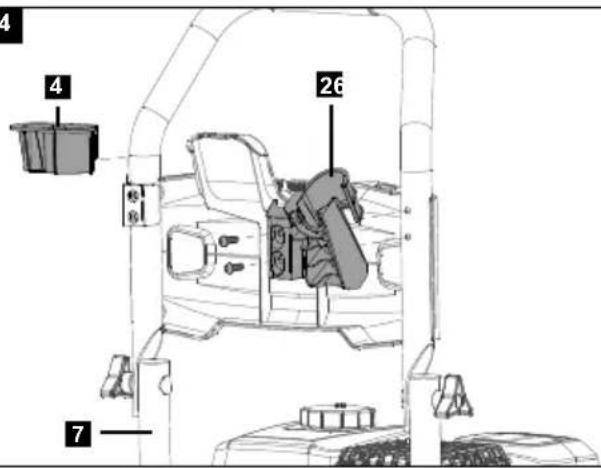
9.3 Fix the transport holder to the bow-type handle (Fig. 4)
- Slide the transport bracket (4) from above into the already pre-assembled mounting on the tubular frame.
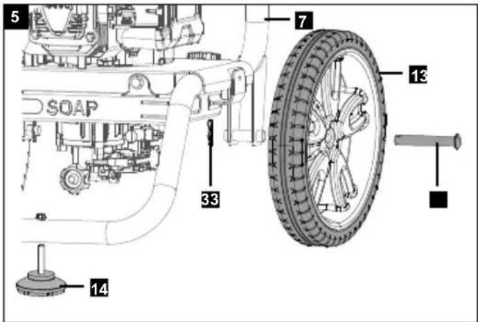
9.4 Fitting the wheels (Fig. 5)
- Slide the axle (32) through the wheel (13) from the outside.
- Now guide the axle (32) with wheel (13) from the outside into the tubular frame (7) and secure it with the spring split pin (33).
- Repeat the process on the opposite side.
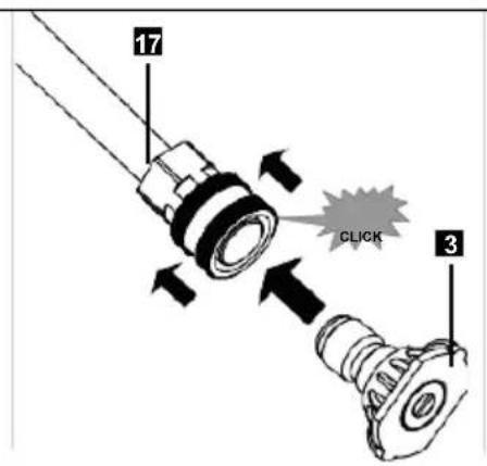
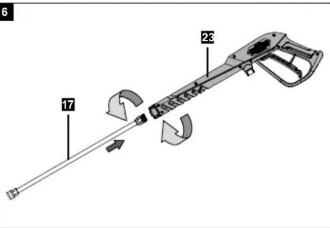
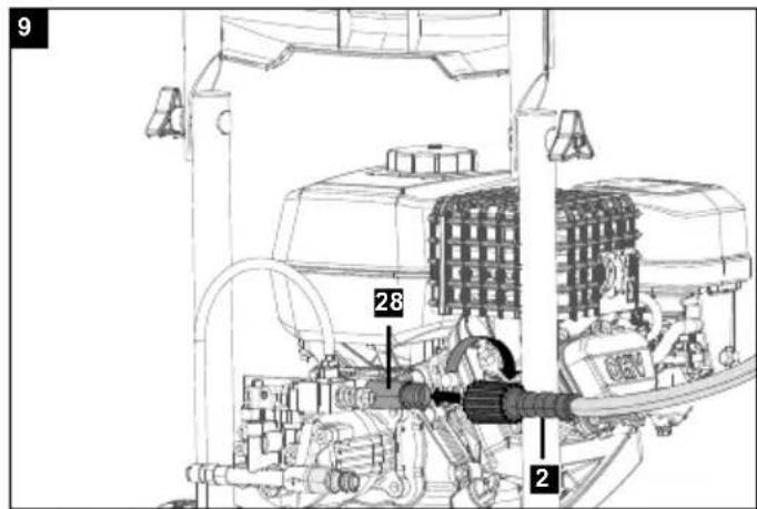
9.5 Fitting the hand spray gun, spraying lance (Fig. 6, 7, 8, 9)
⚠️ DANGER
- Danger of injury! The device, supply lines, high-pressure hose and connections must be in perfect condition. If their condition is not perfect, the device must not be operated.
• Always tighten the fixing by hand! Too loose a connection can lead to disconnection and cause injury.
1. Connect the spraying lance (17) to the hand spray gun (23).
2. Hand-tighten the screwed connection of the spraying lance (17).
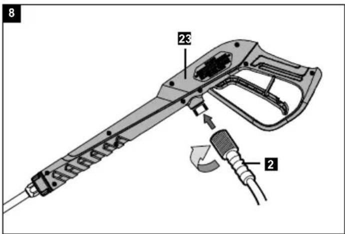
3. Fit the high-pressure hose (2) to the hand spray gun (23).
4. Attach the high-pressure hose (2) to the water outlet (28) by turning the fixing.
10. Before commissioning
ATTENTION
Always make sure the device is fully assembled before commissioning!
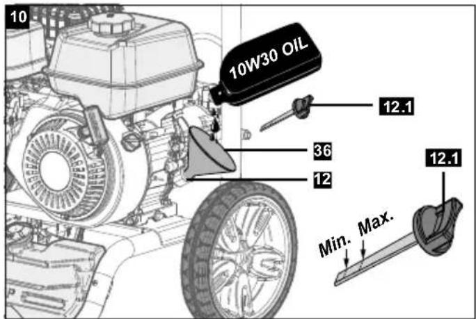
10.1 Filling/checking the engine oil (Fig.10) ATTENTION
• The engine oil must be filled before the first use!
- Check the oil level before each start-up.
- Do not operate the device if no oil is visible on the oil dipstick (12.1).
- Do not overfill the engine oil. Too high an oil level can lead to engine damage.
- Refill the oil if necessary. Only use engine oil (SAE10W30).
- Place the device on a flat, even surface and remove any dirt from the area around the oil inlet/dipstick (12)/oil tank cover with oil dipstick (12.1).
- Open and remove the oil tank cover with oil dipstick (12.1) by turning anti-clockwise.
- Fill the system with max. 400 ml four-stroke engine oil (SAE10W30) as required.
- Check the oil level using the marks on the oil dipstick.
- Place on the oil tank cover with oil dipstick (12.1) and close by turning clockwise.
10.2 Filling in fuel (Fig. 11)
⚠️ DANGER
Risk of fire and explosion!
- Use standard unleaded petrol with max. 10% bioethanol component.
- Never refuel the device in enclosed spaces, with the engine running or hot.
- Do not smoke when refuelling.
- Do not use a two-stroke mixture.
-
Do not refuel near naked flames or sparks.
-
Do not spill fuel. Use funnel.
-
Wipe up spilled fuel.
• After refuelling, close the canister and tank properly. -
Open and remove the fuel tank cover (8) by turning anti-clockwise.
- Place a funnel (36) in the opening of the fuel tank (9).
- Fill the fuel tank (9) with fuel up to max. 3-4 cm below the top edge.
- Replace the fuel tank cover (8) and close the fuel tank (9) by turning clockwise.
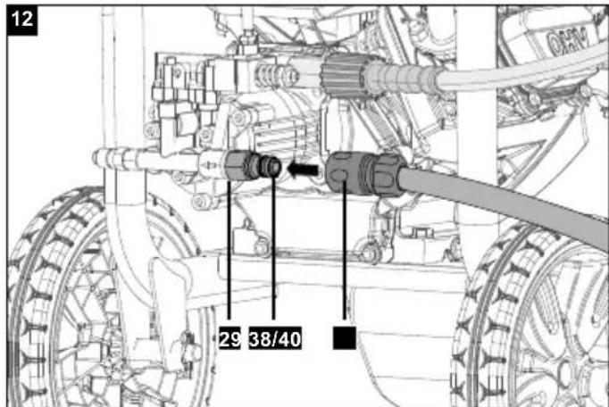
10.3 Connecting the water supply (external) to the pump (Fig. 12)
⚠ WARNING
- If the inlet sieve is missing or damaged, do not operate the high-pressure cleaner. Particles in the high-pressure jet can cause injury.
ATTENTION
- The length of the free garden hose must be at least 3m between the inlet of the high-pressure cleaner and a shut-off device, such as a Y shut-off coupling or other suitable shut-off valve.
-
Do not operate the high-pressure cleaner without a water supply. If the high-pressure cleaner is operated without water, the high-pressure cleaner will be damaged.
-
Before connecting the garden hose (NOT included in the scope of delivery) to the water inlet (29), check the inlet sieve. Clean a contaminated inlet sieve, replace a damaged inlet sieve (40, Fig. 2).
- To remove all impurities, run water through the garden hose for 30 seconds. Shut off the water. Important: Do not suction stagnant water for the water supply. Only use water up to max. 40°C.
- Fit the hose connection adapter (38) on the water inlet (29).
- The garden hose (NOT included in the scope of delivery) can be equipped with the enclosed quick connector (37).
- Connect the garden hose (NOT included in the scope of delivery) to the water inlet (29). The hose must not be longer than 15 m.
- Check that the hose is tightly fitted.
10.4 Self-suction from open tanks/containers and natural bodies of water
⚠️ DANGER
- Never suck up water from a drinking water tank.
- Never suck up liquids containing solvents such as paint thinner, petrol or oil. Solvent spray is highly flammable, explosive and toxic.
Use the self-priming accessories (not included in scope of delivery) consisting of:
- Suction filter
• 3 m reinforced vacuum hose
With this accessory, the device can take in water max.
0.5 m above the water level. This can last about 1 minute.
- Submerge the 3 m vacuum hose completely under water to displace the air.
- Connect the vacuum hose to the device and ensure that the suction filter remains under water.
- Run the device with the hand spray gun removed until water flows evenly from the high-pressure hose.
- If water does not come out after 1 minute, switch off the device and check all connections. Once the water is flowing, turn off the device and connect the hand spray gun and spraying lance to start work.
It is important that the hose and couplers are of good quality, connected tightly and that the seals are undamaged and inserted straight. Leaky connections can hinder suction.
11. Operation
Check the device to make sure that all of the following steps have been performed:
-
Before commissioning the device, read and understand the operating manual completely.
-
Check that the bow-type handle (1) is tightly fitted.
-
Check that oil has been poured into the oil inlet/dipstick to the specified level.
-
Pour the specified type of petrol into the fuel tank (9).
-
Check that the hose connections are tightly fitted.
-
Check that the high-pressure hose (2) has no kinks, cracks or other damage.
-
Have a suitable water connection with sufficient flow ready.
-
Ensure the device is level.
-
Switch on the water supply.
ATTENTION
- Do not switch on the pump if the water supply is not connected or switched on.
- Select the required nozzle (3) and insert it in the spraying lance (17).
11.1 Starting the engine
ATTENTION
- At initial start-up, oil level (SAE10W30) and fuel (unleaded regular petrol) must be filled in.
- Check fuel level and engine oil, top up if necessary.
- Ensure the device has sufficient ventilation.
- Make sure that the spark plug / spark plug connector (31) is secured.
CAUTION
- When starting with the pull starter (18), injuries to the hand can occur due to sudden kick-back.
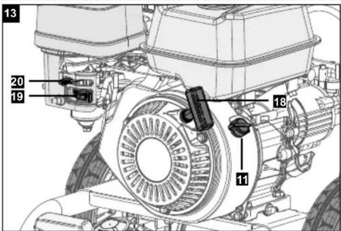
11.1.1 Cold start (Fig. 13)
- Set the choke lever (20) to the "Choke" position.
- Set the on/off switch (11) to the "I/ON" position.
- Open the fuel valve (19).
- Start the engine with the pull starter (18). Pull the handle strongly for this. If the engine does not start, pull the handle again.
- After starting the engine, let the machine run for a few seconds and then set the choke lever (20) to "Run".
11.1.2 Warm start (Fig. 13)
- Set the choke lever (20) to the "Run" position.
- Set the on/off switch (11) to the "I/ON" position.
- Start the engine with the pull starter (18). Pull the handle strongly for this.
11.1.3 After starting the engine (Fig.1)
- Flip the trigger lock (24) on the hand spray gun (23).
- Hold the hand spray gun in a safe direction and pull the trigger (25). This cleans the pump system of air and impurities.
11.2 Switch off the engine (Fig. 13)
- Allow the device to run for a short time without load before switching it off so that the device can "cool down".
- Set the on/off switch (11) to the "0/OFF" position.
- Close the fuel valve (19).
11.2.1 After shutting off the engine
- Connect the water supply.
- Pull the trigger (25) until the device is depressurised.
11.3 Setting the working pressure and flow rate
With this device, the working pressure and flow rate are fixed and cannot be adjusted.
11.4 Changing the nozzle (Fig. 7)
⚠️ DANGER
- Before changing the nozzle, switch off the device and pull the trigger (25) until the device is depressurised.
11.4.1 Using the spray nozzles (Fig. 7)
The quick-release connector on the spraying lance (17) can be used to switch between five nozzles (3).
Proceed as follows to change the nozzles (3):
- Pull back the ring of the quick-release connector and pull off the nozzle (3).
- Select the required nozzle (3):
- Soft jet: 40° (white) or 25° (green)
- Hard jet: 0^ (red)
- Cleaning agent: black
- Pull the ring back, insert the selected nozzle (3) and release the ring. Pull on the nozzle (3) to check the tight fit.
- The best cleaning results are achieved when the nozzle (3) is held at a distance of 20 to 60~cm from the surface to be cleaned. If the distance is too short, the sprayed surface can be damaged.
- When cleaning car tyres, maintain a distance of at least 30 cm.
11.5 Operation with cleaning agents
⚠ WARNING
- Switch off the device before carrying out any setting or maintenance work.
ATTENTION
Unsuitable cleaning agents can damage the device and the object to be cleaned.
- Only use recommended cleaning agents that are suitable for high-pressure cleaners. This device is intended for use with cleaning agents recommended by the manufacturer. The use of other cleaning agents or chemicals may have a negative effect on the safety of the machine.
- Recommended cleaning agents are primarily agents that are suitable for use with high-pressure cleaners. These are available in DIY and car accessories stores, among others.
ATTENTION
Cleaning agents can be harmful to the environment.
- Observe the manufacturer's instructions when using and disposing of the cleaning agent and waste water.
Proceed as follows to work with cleaning agents:
- Prepare the cleaning agent solution according to the manufacturer's instructions.
- Read the instructions for using the nozzles (3) (see 11.4.1).
- Check that the nozzle (3) for cleaning agent (black) has been inserted.
- Open the filler cap for the cleaning agent tank (16).
- Fill the cleaning agent tank (15) with cleaning agent.
ATTENTION
- Cleaning agent must not be applied with the high-pressure nozzles (3) (white, green or red).
- Check that the garden hose is also connected to the water inlet (29) (see 10.3).
- Check whether the high-pressure hose (2) is connected to the hand spray gun (23) and the water outlet (28) (see 9.7).
- Insert nozzle (3) for cleaning agent (black) on spraying lance (10) (see 11.4.1).
- Then start the engine (see 11.1).
11.5.1 Recommended cleaning method
- Loosen dirt: Spray on cleaning agent sparingly and leave to act for 1 - 5 minutes, but do not allow to dry.
- Remove dirt: Rinse off loosened dirt with a high-pressure jet.
11.5.2 After operation with cleaning agent
- After operating with cleaning agent, clean the cleaning agent tank (15) and the connected hoses.
ATTENTION
Do not leave the cleaning agent in the cleaning agent tank (15)!
• Empty the cleaning agent tank (15) after operation.
To clean the cleaning agent tank (15) and the high-pressure pump (30), proceed as follows:
- Pull the trigger (25) of the hand spray gun (23) until the cleaning agent tank (15) is empty.
- Fill the cleaning agent tank (15) with clear water.
- Insert the cleaning agent nozzle (3) (black) on the spraying lance (17).
- Start up the high-pressure cleaner as described in chapter 10.
- Rinse the high-pressure cleaner with clear water for several minutes.
11.6 Interrupting operation
- Release the trigger (25) of the hand spray gun (23).
Note:
When the trigger (25) of the hand spray gun (23) is released, the engine continues to idle.
- Switch off the engine during longer interruptions (several minutes) (see 11.2).
- Pull the trigger (25) until the device is depressurised.
- Secure the hand spray gun (23) with the trigger lock (24) against unintentional opening.
11.7 Work complete
- Switch off the engine at the end of work (see 11.2).
- Shut off the water supply to the high-pressure cleaner.
- Pull the trigger (25) until the device is depressurised.
- Secure the hand spray gun (23) with the trigger lock (24) against unintentional opening.
- Unscrew the water supply hose from the device.
12. Transport
CAUTION
Risk of injury and damage!
• Note the weight of the device during transport.
12.1 Preparation for transport
Note:
Dispose of petrol in an environmentally friendly manner!
- Empty the fuel tank (9) with a petrol extraction pump (not included in the scope of delivery).
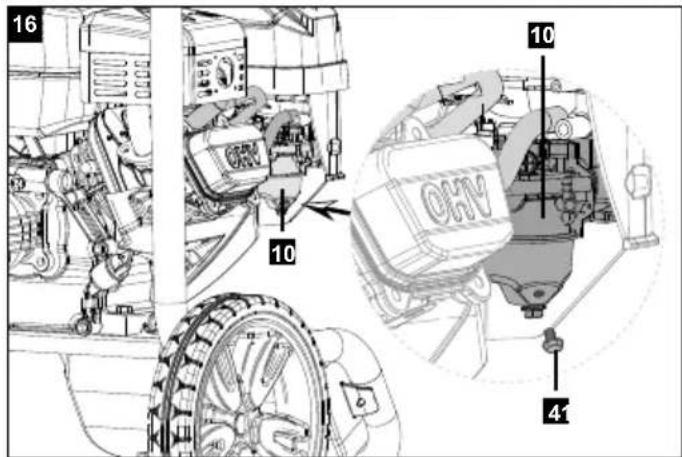
- To ensure that no petrol remains in the carburettor, the remaining petrol in the carburettor must be drained out.
To do this, place a suitable container (not included in the scope of delivery) under the carburettor and open the petrol drain screw (41). (Fig. 16)
-
Drain the engine oil from the warm engine (as described).
-
Remove the spark plug connector (31) from the spark plug.
-
Wind up the high-pressure hose (2) and place it in the hose holder (27).
-
Insert the spraying lance (17) into the transport holder (4) and hang the hand spray gun (23) into the transport holder (4).
-
Slide the device by the bow-type handle (1).
-
When transporting the device in vehicles, secure it against rolling away, slipping and tipping, for example with tension straps, in accordance with the applicable directives.
13. Cleaning
⚠️ DANGER
Danger of injury due to unintentional start-up of the device.
- Before working on the device, turn the engine switch to "0/Off" and remove the spark plug connector.
Danger of burning
- Do not touch hot silencers, cylinders or cooling fins.
⚠ WARNING
- Switch off the device before carrying out any setting or maintenance work.
- Remove the spark plug connector (31).
ATTENTION
- Switch off the device immediately and contact your customer service:
- In the event of unusual vibrations or noises.
- If the engine seems overloaded or misfires.
- Keep protective devices, air vents and the engine housing as free of dust and dirt as possible. Rub the device clean with a dry cloth or blow it off with compressed air at low pressure.
• We recommend that you clean the device directly after every use.
- Clean the device at regular intervals using a damp cloth and a little soft soap. Do not use chemical cleaning agents or solvents. These could damage the plastic parts of the device. Make sure that no water penetrates the device interior.
13.1 Nozzle cleaning
If there is a pulsating sensation when the trigger (24) is pressed, the nozzle (3) is potentially dirty or clogged and should be cleaned immediately.
-
To clean the nozzle (3), switch off the engine and stop the water supply.
-
Depressurise the device (see 11.6).
-
Remove the nozzle (3) from the spraying lance (17). Make sure that the nozzle (3) points away from you in a safe direction.
-
Use the nozzle cleaning needle (34) or a small paper clip to remove debris from the nozzle (3).
-
Rinse the nozzle (3) with clear water.
-
Refit the nozzle (3) to the spraying lance (17).
-
Start the water supply and start the device.
13.2 Draining water
ATTENTION
Risk of damage!
- Freezing water in the device can destroy parts of the device.
In winter, store the device preferably in a heated room.
When storing in an unheated room, proceed as follows:
-
Unscrew the water supply hose and high-pressure hose (2).
-
Let the device run for max. 1 minute until the pump and lines are empty.
14. Maintenance
⚠ WARNING
- Switch off the device before carrying out any setting or maintenance work.
- Remove the spark plug connector (31).
⚠️ DANGER
Danger of injury due to unintentional start-up of the device.
- Before working on the device, turn the engine switch to "0/Off" and remove the spark plug connector.
Danger of burning
- Do not touch hot silencers, cylinders or cooling fins.
14.1 Maintenance intervals
Before commissioning:
- Check the oil level on the oil tank cover with oil dipstick (12.1).
- If the oil is milky (water in the oil), contact customer service immediately.
- Check the high-pressure hose (2) for damage (danger of bursting). Replace a damaged high-pressure hose (2) immediately.
Every 25 operating hours:
- Check the oil level on the oil tank cover with oil dipstick (12.1).
- If the oil is milky (water in the oil), contact customer service immediately.
Every 50 operating hours:
- Check the oil level on the oil tank cover with oil dipstick (12.1).
- If the oil is milky (water in the oil), contact customer service immediately.
- Clean the air filter.
- Check the fasteners between the engine and the frame for cracks and have cracked fasteners replaced by customer service.
14.2 Maintenance tasks
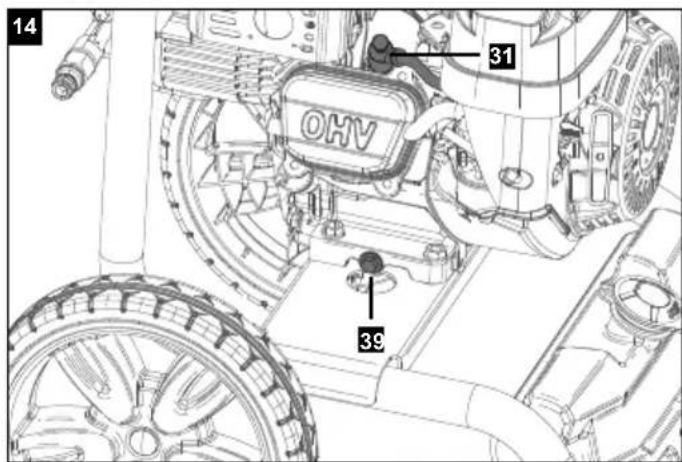
14.2.1 Changing the engine oil (Fig. 10/14)
Note:
Dispose of used oil in an environmentally friendly manner!
The engine oil change should be carried out while the engine is at operating temperature.
- Provide a collection bucket for approx. 1 litre of oil.
- Place the device on a suitable surface.
- Open the oil drain screw (39) (Fig. 14).
- Drain the engine oil into the collection buckets provided.
- To speed up the draining of the engine oil, you can open the oil tank cover with oil dipstick (12.1).
- After the used oil has drained out, close the oil drain screw (39) and put the device back on level ground.
- Fill engine oil up to the top marking on the oil dipstick (12.1).
For oil type and filling quantity, see Technical Data.
ATTENTION
- To check the oil level, do not screw in the oil tank cover with oil dipstick (12.1), but only insert it up to the thread.
14.2.2 Air filter (Fig. 1)
Clean the air filter (21) regularly, replace if necessary.
- Remove the air filter cover (21). Pull carefully on the edges of the air filter (21).
- Remove the contaminated filter element.
- Knock out the contaminated filter element or blow it out with compressed air at low pressure.
- Replace the filter element and the air filter cover (21).
14.2.3 Spark plug (Fig. 14)
Check the spark plug / spark plug connector (31) forcontamination for the first time after 20 operating hoursand clean it with a copper wire brush if necessary.Then service the spark plug every 50 operating hours.
- Remove the spark plug connector (31) from the spark plug by turning it.
- Remove the spark plug with the enclosed spark plug wrench (35).
- The re-assembly takes place in reverse order.
14.3 Service information
With this product, it is necessary to note that the following parts are subject to natural or usage-related wear, or that the following parts are required as consumables. Wearing parts*: Spark plug, high-pressure hose, spraying lance, nozzles, air filter
* may not be included in the scope of delivery!
Spare parts and accessories can be obtained from our Service Centre. To do this, scan the QR code on the front page.
15. Storage
CAUTION
Risk of injury and damage!
• Note the weight of the device during transport.
Store the device and its accessories in a dark, dry and frost-free place that is inaccessible to children. The optimum storage temperature is between 5 and 30°C. Cover the device to protect it from dust or moisture.
Store the operating instructions with the device.
15.1 Preparation for storage
Note:
Dispose of petrol in an environmentally friendly manner!
- Empty the fuel tank (9) with a petrol extraction pump (not included in the scope of delivery).
- To ensure that no petrol remains in the carburettor, the remaining petrol in the carburettor must be drained out. To do this, place a suitable container (not included in the scope of delivery) under the carburettor and open the petrol drain screw (41). (Fig. 16)
- Change the oil at the end of every season. To do so, remove the used engine oil from a warm engine and refill with fresh oil.
- Remove the spark plug. Fill approx. 20 ml of oil into the cylinder using an oil can (not included in scope of delivery). Pull the pull starter (18) slowly so that the oil coats the inside of the cylinder. Attach the spark plug again.
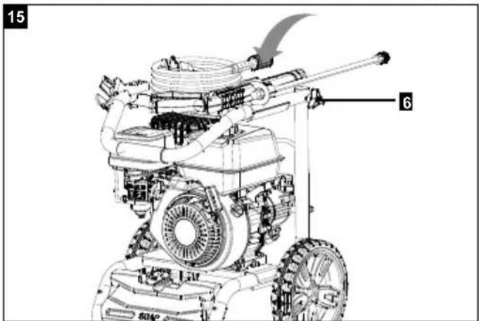
- Open the star grip screws (6) and fold the device in (Fig. 15).
- Store the device in a well-ventilated place or area.
17. Troubleshooting
WARNING
Danger of injury due to unintentional start-up of the device!
- Before working on the device, turn the on/off switch (11) to the "Off" position and remove the spark plug connector (31).
WARNING
Danger of burning!
- Do not touch hot silencers, cylinders or cooling fins.
ATTENTION
- If the fault cannot be rectified, the device must be checked by customer service.
Important note in the case of repairs:
When returning the device for repair, for safety reasons, ensure that it is free of oil and fuel when it is sent to the service centre.
| Fault Possible cause | Remedy | |
| Engine cannot be started | Automatic oil cut-off trips | Check oil level, fill with engine oil |
| Spark plug sooty | Clean or replace spark plug | |
| No fuel | Top up with fuel | |
| Spark plug connector is disconnected | Connect the spark plug connector to the spark plug | |
| Spark plug connector is damaged | Contact Customer Service | |
| Ignition does not work | Contact Customer Service | |
| Engine is difficult to start Out-of-date fuel or water in fuel Drain fuel and fill with new fuel | ||
| Engine has too little power and vibrates excessively | Contaminated air filter Clean the air filter | |
| Engine dies during operation No fuel Top up with fuel | ||
| Engine loses power during operation Engine speed is too low Operate the trigger slower. If the fault persists, contact Customer Service | ||
| Device does not build up pressure Nominal speed of the engine too slow | Check the nominal speed of the engine; contact customer service | |
| Low-pressure nozzle fitted Fit the high-pressure nozzle | ||
| Nozzle clogged / washed out Clean / renew nozzle | ||
| Suction filter clogged Clean the suction filter | ||
| Air in the system Bleed the device (see “Before commissioning”) | ||
| Water supply volume too low | Check the water supply volume | |
| Supply line to the high-pressure pump leaking or clogged | Check all supply lines to the high-pressure pump. Contact Customer Service | |
| Pump is defective | Contact Customer Service | |
| Device leaks, water drips from the bottom of the device | The high-pressure pump leaks | A maximum of 3 drops / minute is permissible. In case of severe leakage, have the device checked by customer service |
| Cleaning agent is not sucked in | High-pressure nozzle fitted | Fit the low-pressure nozzle |
| Cleaning agent hose leaking or blocked | Check or clean the cleaning agent hose | |
Table des matières: Page:
Günzburger Straße 69
D-89335 Ichenhausen
Cher client,
Günzburger Straße 69
D-89335 Ichenhausen, Germania
Egregio cliente,
Günzburger Straße 69
D-89335 Ichenhausen
Geachte klant,
Günzburger Straße 69
Günzburger Straße 69
9.4 Montar as rodas (fig. 5)
Günzburger Straße 69
D-89335 Ichenhausen
Vážený zákazníku,
Günzburger Straße 69
D-89335 Ichenhausen
Vážený zákazník,
Günzburger Straße 69
D-89335 Ichenhausen
Kedves Ügyfelünk!
Günzburger Straße 69
D-89335 Ichenhausen
Szanowny Kliencie,
Günzburger Straße 69
D-89335 Ichenhausen
Poštovani kupci,
Günzburger Straße 69
D-89335 Ichenhausen
Spoštovani kupec,
želimo vam veliko veselja in uspeha pri delu z vašo novo napravo.
Napotek:
Negotovost K_pA 3 dB
Nivo moči zvoka L _WA 105 dB
Negotovost K_WA 3 dB
Günzburger Straße 69
D-89335 Ichenhausen
Austatud klient!
Günzburger Straße 69
D-89335 Ichenhausen
Gerbiamas kliente,
Günzburger Straße 69
Günzburger Straße 69
D-89335 Ichenhausen
Bästa kund!
Günzburger Straße 69
D-89335 Ichenhausen
Arvoisa asiakas,
Günzburger Straße 69
D-89335 Ichenhausen, Tyskland
Kære kunde,
Günzburger Straße 69
D-89335 Ichenhausen
Kjære kunde,
12.1 Forberedelse for transport
Merknad:
Günzburger Straße 69
D-89335 Ichenhausen, Германия
Уважаеми клиенти,
Günzburger Straße 69
D-89335 Ichenhausen
Αξιότιμε πελάτη,
Günzburger Straße 69
D-89335 Ichenhausen
Stimate client,
Günzburger Straße 69
D-89335 Ichenhausen
Poštovani kupče,
Günzburger Straße 69
D-89335 Ichenhausen
ithalatçı:
EU Declaration of Conformity
Standard references:
EN 60335-1:2012/A11:2014+A13:2017; EN 60335-2-79:2012; EN 55012:2007+A1; DIN EN 61000-6-1:2007
This declaration of conformity is issued under the sole responsibility of the manufacturer.
The object of the declaration described above fulfils the regulations of the directive 2011/65/EU of the European Parliament and Council from 8th June 2011, on the restriction of the use of certain hazardous substances in electrical and electronic equipment.
Subject to change without notice
Documents registrar: Georg Kohler
Günzburger Str. 69, D-89335 Ichenhausen
EU Declaration of Conformity
| X | 2000/14/EG_2005/88/EG | |
| Noise: measured LWA= xx dB; guaranteed LWA= 105 dB | ||
| x | Annex V | |
| Annex VI | ||
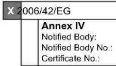
| X | 2006/42/EG | |
| Annex IV Notified Body: Notified Body No.: Certificate No.: | ||
| X | 2016/1628/EU |
| type-approval number: e24*2016/1628*2018/989SRA1/P*0466*00 |
Standard references:
EN 60335-1:2012/A11:2014+A13:2017; EN 60335-2-79:2012; EN 55012:2007+A1; DIN EN 61000-6-1:2007
This declaration of conformity is issued under the sole responsibility of the manufacturer.
The object of the declaration described above fulfils the regulations of the directive 2011/65/EU of the European Parliament and Council from 8th June 2011, on the restriction of the use of certain hazardous substances in electrical and electronic equipment.
Subject to change without notice
Documents registrar: Georg Kohler
Günzburger Str. 69, D-89335 Ichenhausen
EU Declaration of Conformity
AB uygunluk beyanı
CE
Scheppach GmbH, Günzburger Str. 69, D-89335 Ichenhausen
| DE | erklärt folgende Konformität gemäß EU-Richtlinien und Normen für den Artikel | RO | declară următoarea conformitate corespunzător directivelor și normelor UE pentru articolul |
| GB | hereby declares the following conformity under the EU Directive and standards for the following article | GR | δηλώνει την ακόλουθη συμμόρφωση σύμφωνα με την Οδηγία ΕΕ και τα πρότυπα για το προϊόν |
| BG | декларира съответното съответствие съгласно Дирек-тива на ЕС и норми за артикул | TR | Burada açıklanan ürünün geçerli yönetmeliklere ve standartlara uygun olduğunu tamamen kendi sorumluluğumuz altında beyan ediyoruz. |
| RS | potvrđuje sledeću usklađenost prema smernicama EZ i normama za artikal |

Standard references:
EN 60335-1:2012/A11:2014+A13:2017; EN 60335-2-79:2012; EN 55012:2007+A1; DIN EN 61000-6-1:2007
This declaration of conformity is issued under the sole responsibility of the manufacturer.
The object of the declaration described above fulfils the regulations of the directive 2011/65/EU of the European Parliament and Council from 8th June 2011, on the restriction of the use of certain hazardous substances in electrical and electronic equipment.
Subject to change without notice
Documents registrar: Georg Kohler Günzburger Str. 69, D-89335 Ichenhausen
Garantie DE
Apparent defects must be notified within 8 days from the receipt of the goods. Otherwise, the buyer loses its rights of claim due to such defects are invalidated. We guarantee for our machines in case of proper treatment for the time of the statutory warranty period from delivery in such a way that we replace any machine part free of charge which provably becomes unusable due to faulty material or defects of fabrication within such period of time. With respect to parts not manufactured by us we only warrant insofar as we are entitled to warranty claims against the upstream suppliers. The costs for the installation of the new parts shall be borne by the buyer. The cancellation of sale or the reduction of purchase price as well as any other claims for damages shall be excluded.
Garantie FR
Apparent defects must be notified within 8 days from the receipt of the goods. Otherwise, the buyer's rights of claim due to such defects are invalidated. We guarantee for our machines in case of proper treatment for the time of the statutory warranty period from delivery in such a way that we replace any machine part free of charge which provably becomes unusable due to faulty material or defects of fabrication within such period of time. With respect to parts not manufactured by us we only warrant insofar as we are entitled to warranty claims against the upstream suppliers. The costs for the installation of the new parts shall be borne by the buyer. The cancellation of sale or the reduction of purchase price as well as any other claims for damages shall be excluded.
Záruka CZ
Apparent defects must be notified within 8 days from the receipt of the goods. Otherwise, the buyer is rights of claim due to such defects are invalidated. We guarantee for our machines in case of proper treatment for the time of the statutory warranty period from delivery in such a way that we replace any machine part free of charge which provably becomes unusable due to faulty material or defects of fabrication within such period of time. With respect to parts not manufactured by us we only warrant insofar as we are entitled to warranty claims against the upstream suppliers. The costs for the installation of the new parts shall be borne by the buyer. The cancellation of sale or the reduction of purchase price as well as any other claims for damages shall be excluded.
Garantii EE
Apparent defects must be notified within 8 days from the receipt of the goods. Otherwise, the buyer's rights of claim due to such defects are invalidated. We guarantee for our machines in case of proper treatment for the time of the statutory warranty period from delivery in such a way that we replace any machine part free of charge which provably becomes unusable due to faulty material or defects of fabrication within such period of time. With respect to parts not manufactured by us we only warrant insofar as we are entitled to warranty claims against the upstream suppliers. The costs for the installation of the new parts shall be borne by the buyer. The cancellation of sale or the reduction of purchase price as well as any other claims for damages shall be excluded.