PPT-01 - Hydraulic clamp MSW - Free user manual and instructions
Find the device manual for free PPT-01 MSW in PDF.

User questions about PPT-01 MSW
0 question about this device. Answer the ones you know or ask your own.
Ask a new question about this device
Download the instructions for your Hydraulic clamp in PDF format for free! Find your manual PPT-01 - MSW and take your electronic device back in hand. On this page are published all the documents necessary for the use of your device. PPT-01 by MSW.
USER MANUAL PPT-01 MSW
natural_image
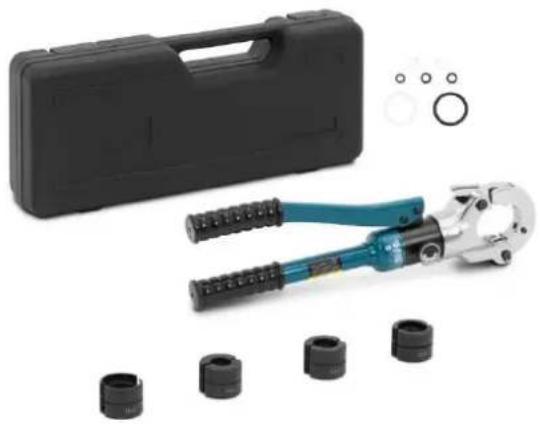
Assorted mechanical tools including a crimping tool, a black hard case, and multiple black cylindrical components (no text or symbols visible)natural_image
Close-up of a hand holding a cylindrical mechanical tool with a handle and labeled component (no text or symbols visible)natural_image
Close-up of a mechanical component with labeled parts (1 and A), no readable text or symbols beyond labels
natural_image
Close-up of a mechanical assembly with a metallic shaft and black housing (no visible text or symbols)natural_image
Mechanical component diagram showing a clamp or lever mechanism with labeled parts (1 and 2), no readable text or symbols beyond labels.natural_image
Close-up of a mechanical clamp or tool with a black handle and metallic components (no visible text or symbols)natural_image
Close-up of hands using a crimping tool to handle a cylindrical component (no visible text or symbols)natural_image
Close-up of a mechanical assembly with a cylindrical component and a rod inserted, labeled with number 1 (no text or symbols on the main subject)text_image
Labeled diagram of a mechanical tool kit with numbered parts for identification1- Dupperkopf
2- Stanzformen
3- Untere Matrizenbasis
This User Manual has been translated using machine translation. We have made every effort to ensure the translation is accurate, but please note that automated translations are not perfect and are not meant to replace human translators. The official version of the User Manual is in English. Any differences between the translated version and the original English are not legally binding. If you have any questions about the accuracy of the translation, please refer to the English version, which is the official reference. More language versions are available upon request via info@expondo.com.
Technical data
| Parameter description | Parameter value |
| Product name | Hydraulic crimping pliers |
| Model | MSW-PPT-01 |
| Capacity max output [ton] | 6 |
| Pipe dimensions [mm] | 16-32 |
| Dimensions (Width x Length x Height) [mm] | 110x420x70 |
| Weight [kg] | 3.75 |
Product overview
natural_image
Assorted mechanical tools including a crimping tool, plastic housing, and multiple black cylindrical components (no text or symbols visible)The product is a specialized tool designed to securely attach connectors, such as lugs or terminals, to electrical wires using hydraulic pressure. The product is commonly used in electrical installations, automotive repairs, and telecommunications to ensure strong, reliable connections that can withstand high electrical loads. The hydraulic mechanism amplifies force, making it easier to achieve consistent, precise crimps without manual effort, ensuring optimal performance and durability.
The user is liable for any damage resulting from unintended use of the product.
Usage

WARNING
- Read and understand all instructions and safety information in this manual before operating or servicing this tool. Failure to do so may result in damage to pipes and fittings.
- Electrical Shock Hazard: This tool is not insulated. Use appropriate protective equipment when operating this unit near energized electrical lines.
- Do NOT operate the tool without the pressing dies installed.
- High Pressure Hazard: Do not use fingers or hands to check for oil leaks. High-pressure oil can easily puncture skin, causing serious injury.

CAUTION
- Inspect the tool before use. Check for loose screws, misalignment or binding of moving parts, cracked or broken parts, or any other condition that may affect its safe operation. Replace any worn or damaged parts. A damaged or improperly assembled tool can malfunction, cause pipe fittings damage.

IMPORTANT
- The dust or air inside the machine will damage the sealing kit and cause the tool to lose function. Make sure the oil is clear when changing oil. Wait for a while and exhaust the oil completely out of the oil bag before inserting the oil plug.
- Do not place the tool in a vise. The hydraulic press tool is designed for hand-held operation.
- Choose the right size pressing dies (2), according to the round edge of bottom die base (3) and upper tool head (1). Press the dies-lock (17) deeply and insert the dies and keep steady.
- Close the head latch (5) completely.
- Turn and tighten the release knob to make the dies close, make sure the dies (2) closed tight and not malposed.
• Lift the head latch (5) to open the press tool upper head (1). - Use the tool now.
- When the pressing work is complete, turn the release knob to retract the bottom die base (3).

NOTE
- Clean the external surface of the tool with a moist cloth and smear with rust preventing oil.
• Store in a dry environment, keep the tool clean.
Operating instructions
- Check for appropriate work area.
- Inspect the work to be done and determine the correct tool and dies for the application per their specifications. Using incorrect equipment for an application can cause injury, damage the tool and make incomplete connections.
- Make sure all equipment has been inspected and set up as directed in their instructions.
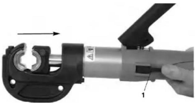
- Removing/Installing Dies in crimp head. Depress the Release Lever to fully retract the movable die holder (Figure 1).
natural_image
Close-up of a hand using a mechanical tool to adjust a cylindrical component, with no visible text or symbols.Figure 1 Fully retracting die holder
1- Release Lever
natural_image
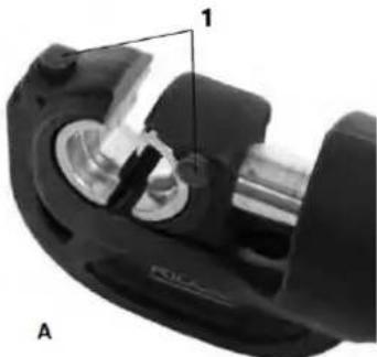
Close-up of a mechanical component with labeled parts (1 and A), no readable text or symbols beyond labelsFigure 2 – A. Dies Aligned

natural_image
Close-up of a mechanical assembly with black components and a metallic shaft (no visible text or symbols)B. Dies Misaligned
1- Die Release Buttons
Depress the die release buttons to allow the dies to slide laterally in and out of the die holders. Do not force dies into die holders. Dies should fit snugly and securely, and the crimp profiles should align (Figure 2). Dies should not move unless the die release button is depressed. Always use a matched set of dies. If there are any issues regarding proper die fit, do not use the tool. Do not operate the tool without the dies installed.
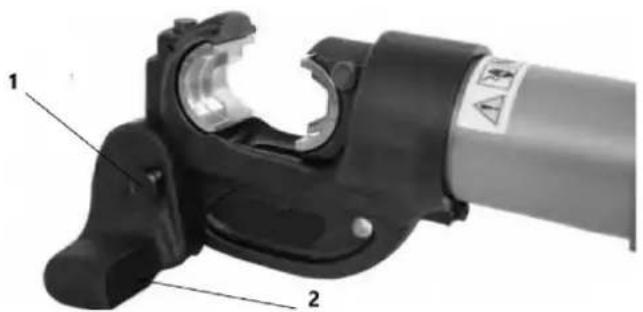
5. Removing/Installing the Crimp Head Stand.
When working with the Crimp Tool on the ground, the crimp head stand can be used to support and stabilize the Crimp Tool.
natural_image
Close-up of a mechanical clamp or lever component with labeled parts (1 and 2), no readable text or symbols beyond labelsFigure 3 Installing the Crimp Head on the Stand
1- Lock Pin
2- Crimp Head Stand
The stand mounts to the Crimp Head with a lock pin through a hole. Fully insert the lock pin. See
Figure 3.
-
Prepare the connection to be crimped per the connector manufacturer's instructions.
-
Depress the release lever to fully retract the moving die holder.
-
Follow all compression connector manufacturers' instructions for crimp location. Some wire sizes may require more than one crimp per connection.
Center the connector squarely against the crimp profile in the stationary die. Improper placement can result in an incorrect crimp or damage the equipment.
If making a single crimp, line up the dies within the line on the connector. If making multiple crimps on the connector, ensure there is enough room to evenly space crimps between lug lines.
natural_image
Close-up of a mechanical tool with metal components and a black handle (no visible text or symbols)Figure 4 Aligning the Connector
- With hands clear of the dies and other moving parts, pump the Movable Handle to advance the moving die until the dies slightly touch the connector. Confirm that the connector is properly located in the dies (Figure 4).
natural_image
Close-up of hands using a crimping tool to handle a cylindrical component (no text or symbols visible)Figure 5 Using Crimp Tool
- Continue to pump the Movable Handle until the pressure relief valve activates. This is indicated by a sudden and significant decrease of the handle force. An audible popping sound may also be heard. Visually inspect the dies as the pressure relief valve activates – they should be touching or very close to touching. (See Figure 6.) Do not use handle extensions, they can damage the tool or slip and cause injury.
natural_image
Close-up of a mechanical component with a cylindrical shaft and threaded rod, labeled with number 1 (no text or symbols on the object itself)Figure 6 Inspecting Dies as Pressure Relief Valve activates
Do not retract the movable die until the pressure relief valve activates. If the pressure relief valve does not activate, the crimp is not complete and must be repeated.
-
Press the release lever to retract the movable die. If needed, move the head and repeat the procedure for multiple crimps, following the connector manufacturer's instructions for crimp location.
-
Remove the crimped connection from the head.
-
Inspect and test the connection in accordance with connector manufacturer instructions, normal practice and applicable codes.
Cleaning and Maintenance

WARNING Maintain the tool according to these procedures to prolong the product's life and to reduce the risk of injury.
Cleaning
After each use, wipe any oil or dirt off the crimp tool and dies with a clean, dry, soft cloth. Pay special attention to the moving head ram to remove any dirt or debris that could scratch polished parts or damage seals.
Lubrication
Monthly, or more often if needed, apply a light machine oil or grease to the handle pivot points. Wipe off any excess lubricant.
Required Maintenance
The tool should be maintained once a year or more often with heavy use or in extreme conditions. This maintenance will include verifying tool output force and changing the hydraulic fluid.
Storage
Store the tool in the carrying case and place in a dry, secured area that is out of reach of children and people unfamiliar with such tools. The electrical tool is dangerous in the hands of untrained users. Storage area temperature should be between -20^ to 40^ ( -4^ to 104^ ) and humidity less than 80% RH.
Disposal
Parts of the this tool contain valuable materials and can be recycled. There are companies that specialize in recycling that may be found locally. Dispose of the components and oil in compliance with all applicable regulations. Contact your local waste management authority for more information.
Parts
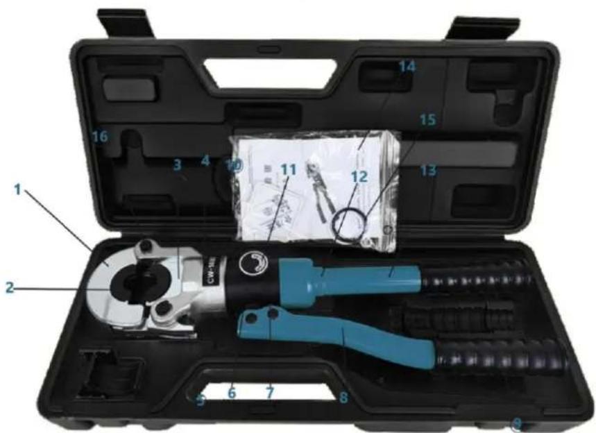
text_image
Labeled diagram of a mechanical tool kit with numbered parts for identification1- Dupper die head
2- Pressing dies
3- Bottom die base
4- Bottom tool head
5- Head latch
6- Handle base
7- Pumping core
8- Active handle
9- Handle sleeve
10- Cylinder
11- ON/OFF switch
12- Solid handle
13- CAUTION label
14- User manual
15- Spare sealing kit
16- Lock Pin

natural_image
Assorted mechanical tools including a crimping tool, black case, and multiple cylindrical components (no text or symbols visible)natural_image
Close-up of a hand holding a cylindrical mechanical tool with a handle and internal components, no visible text or symbols.natural_image
Close-up of a mechanical component with labeled parts (1 and A), no readable text or symbols beyond labels
natural_image
Close-up of a mechanical component with a metallic shaft and internal cavities (no visible text or symbols)natural_image
Mechanical component diagram showing a lever mechanism with labeled parts (1 and 2), no readable text or symbols beyond labelsnatural_image
Close-up of a mechanical clamp or tool with metal components and a black handle (no visible text or symbols)natural_image
Close-up of hands using a crimping tool to handle a cylindrical component (no visible text or symbols)natural_image
Close-up of a mechanical assembly with a cylindrical component and a rod inserted, labeled with number 1 (no text or symbols on the object itself)text_image
Labeled diagram of a mechanical tool kit with numbered parts for identificationnatural_image
Product photo of a crimping tool kit with a black case, multiple black cylindrical seals, and a separate inset showing circular features (no text or symbols visible)natural_image
Close-up of a hand holding a cylindrical mechanical tool with a handle, showing internal components and an arrow indicating motion (no text or symbols visible)natural_image
Close-up of a mechanical component with labeled parts (1 and A), no readable text or symbols beyond labels
natural_image
Close-up of a mechanical component with metallic parts and a labeled section B (no visible text or symbols)natural_image
Mechanical component diagram showing a lever handle and clamp mechanism (no text or symbols)natural_image
Close-up of a mechanical tool with a black handle and metallic components (no visible text or symbols)natural_image
Close-up of hands using a crimping tool to handle a cylindrical component (no text or symbols visible)natural_image
Close-up of a mechanical component with a cylindrical shaft and flange, labeled with number 1 (no text or symbols on the object itself)text_image
Labeled diagram of a mechanical tool kit with numbered parts for identification1- Dupperova hlava
2- Lisovací matrice
natural_image
Assorted mechanical tools including a crimping tool, a black hard case, and multiple black cylindrical components (no text or symbols visible)natural_image
Close-up of a hand holding a cylindrical mechanical tool with a handle and internal components, no visible text or symbols.natural_image
Close-up of a mechanical component with labeled parts (1 and A), no readable text or symbols beyond labels
natural_image
Close-up of a mechanical assembly with a cylindrical component and flanged housing (no visible text or symbols)natural_image
Mechanical component diagram showing a clamp or lever mechanism with labeled parts (1 and 2), no readable text or symbols beyond labels.natural_image
Close-up of a mechanical tool with metal clamps and a black handle (no visible text or symbols)natural_image
Close-up of hands using a crimping tool to handle a cylindrical component (no visible text or symbols)natural_image
Close-up of a mechanical assembly with a cylindrical component and a rod inserted, labeled with number 1 (no text or symbols on the object itself)text_image
Labeled diagram of a mechanical tool kit with numbered parts for identificationnatural_image
Assorted mechanical tools including a crimping tool, plastic housing, and multiple black cylindrical components (no text or symbols visible)natural_image
Close-up of a hand holding a cylindrical mechanical tool with a handle and labeled component (no text or symbols visible)natural_image
Close-up of a mechanical component with labeled parts (1 and A), no readable text or symbols beyond labels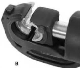
natural_image
Close-up of a mechanical component with no visible text or symbolsFigura 2 – A. Matrici allineate B. Matrici disallineate
natural_image
Mechanical component diagram showing a clamp or lever mechanism with labeled parts (1 and 2), no readable text or symbols beyond labels.natural_image
Close-up of a mechanical clamp or tool with a black handle and metallic components (no visible text or symbols)natural_image
Close-up of hands using a manual crimping tool to handle a cylindrical component (no text or symbols visible)natural_image
Close-up of a mechanical assembly with a cylindrical component and a rod inserted, labeled with number 1 (no text or symbols on the object itself)text_image
Labeled diagram of a mechanical tool kit with numbered parts for identificationnatural_image
Assorted mechanical tools including a crimping tool, a black hard case, and multiple black cylindrical components (no text or symbols visible)natural_image
Close-up of a hand holding a cylindrical mechanical component with a lever and labeled part (1), no visible text or symbols on the device itself.natural_image
Close-up of a mechanical component with labeled parts (1 and A), no readable text or symbols beyond labels
natural_image
Close-up of a mechanical assembly with a metallic component and black housing (no visible text or symbols)Figura 2 – A. Matrices alineadas B. Matrices desalineadas
natural_image
Mechanical component diagram showing a clamp or lever mechanism with labeled parts (1 and 2), no readable text or symbols beyond labels.natural_image
Close-up of a mechanical clamp or tool with black and metallic components (no visible text or symbols)natural_image
Close-up of hands using a crimping tool to handle a cylindrical component (no visible text or symbols)natural_image
Close-up of a mechanical assembly with a cylindrical component and a rod inserted, labeled with number 1 (no text or symbols on the object itself)text_image
Labeled diagram of a mechanical tool kit with numbered parts for identification1- Cabezal de troquel Dupper
natural_image
Assorted mechanical tool including a crimping tool, a black hard case, and multiple black plastic components (no text or symbols visible)natural_image
Close-up of a hand holding a cylindrical mechanical tool with a handle and labeled component (no text or symbols visible)natural_image
Close-up of a mechanical component with labeled parts (1 and A), no readable text or symbols beyond labels
natural_image
Close-up of a mechanical component with no visible text or symbolsnatural_image
Mechanical component diagram showing a clamp or lever mechanism with labeled parts (1 and 2), no readable text or symbols present.natural_image
Close-up of a mechanical clamp or tool with metal components and a black handle (no visible text or symbols)natural_image
Close-up of hands using a crimping tool to handle a cylindrical component (no visible text or symbols)natural_image
Close-up of a mechanical assembly with a cylindrical component and a rod inserted, labeled with number 1 (no text or symbols on the main subject)text_image
Labeled diagram of a mechanical tool kit with numbered parts for identificationnatural_image
Assorted mechanical tools including a crimping tool, plastic housing, and multiple black cylindrical components (no text or symbols visible)natural_image
Close-up of a hand holding a cylindrical mechanical tool with a handle and labeled component (no text or symbols visible)natural_image
Close-up of a mechanical component with labeled parts (1 and A), no readable text or symbols beyond labels
natural_image
Close-up of a mechanical assembly with a metallic cylindrical component and black housing (no visible text or symbols)Figur 2 - A. Matricer justeret B. Matricer forkert justeret
1- Udløserknapper til matricer
natural_image
Close-up of a mechanical clamp or lever component with labeled parts (1 and 2), no readable text or symbols beyond labelsnatural_image
Close-up of a mechanical tool with metal clamping and a black handle (no visible text or symbols)Figur 4 Justering af stikket
natural_image
Close-up of hands using a crimping tool to handle a cylindrical component (no visible text or symbols)natural_image
Close-up of a mechanical component with a cylindrical shaft and flange, showing internal components and a labeled part '1' (no text or symbols beyond label)Figur 6 Inspektion af matricer, när overtryksventilen aktiveres
text_image
Labeled diagram of a mechanical tool kit with numbered parts for identificationnatural_image
Assorted mechanical tools including a crimping tool, plastic housing, and multiple black cylindrical components (no text or symbols visible)natural_image
Close-up of a hand using a mechanical tool to adjust a cylindrical component, showing no text or symbols.natural_image
Close-up of a mechanical component with labeled parts (1 and A), no readable text or symbols beyond labels
natural_image
Close-up of a mechanical assembly with black components and a metallic shaft (no visible text or symbols)natural_image
Close-up of a mechanical clamp or lever component with labeled parts (1 and 2), no readable text or symbols beyond labelsnatural_image
Close-up of a mechanical clamp or tool with black and metallic components (no visible text or symbols)natural_image
Close-up of hands using a crimping tool to handle a cylindrical component (no visible text or symbols)natural_image
Close-up of a mechanical component with a cylindrical shaft and threaded rod inserted, labeled with number 1 (no text or symbols on the object itself)text_image
Labeled diagram of a mechanical tool kit with numbered parts for identificationnatural_image
Assorted mechanical tools including a crimping tool, black case, and multiple black cylindrical components (no text or symbols visible)natural_image
Close-up of a hand holding a cylindrical mechanical tool with a handle and labeled component (no text or symbols visible)natural_image
Close-up of a mechanical component with labeled parts (1 and A), no readable text or symbols beyond labels
natural_image
Close-up of a mechanical assembly with a metallic shaft and black housing (no visible text or symbols)natural_image
Mechanical component diagram showing a clamp or lever mechanism with labeled parts (1 and 2), no readable text or symbols present.natural_image
Close-up of a mechanical clamp or tool with metal components and a black handle (no visible text or symbols)natural_image
Close-up of hands using a crimping tool to handle a cylindrical component (no visible text or symbols)natural_image
Close-up of a mechanical assembly with a cylindrical component and a rod inserted, no visible text or symbolstext_image
Labeled diagram of a mechanical tool kit with numbered parts for identificationnatural_image
Assorted mechanical tools including a crimping tool, black case, and multiple black cylindrical components (no text or symbols visible)natural_image
Close-up of a hand holding a cylindrical mechanical tool with a valve and adjustment knob (no visible text or symbols)natural_image
Close-up of a mechanical component with labeled parts (1 and A), no readable text or symbols beyond labels
natural_image
Close-up of a mechanical assembly with a metallic component and black housing (no visible text or symbols)Figur 2 – A. Dies justert B. Dies feiljustert
1- Utløserknapper
natural_image
Mechanical component diagram showing a lever handle and clamp mechanism (no text or symbols)natural_image
Close-up of a mechanical tool with a black handle and metal bracket (no visible text or symbols)Figur 4 Justere kontakten
natural_image
Close-up of hands using a crimping tool to handle a cylindrical component (no text or symbols visible)Figur 5 Bruke Crimp Tool
natural_image
Close-up of a mechanical component with a cylindrical shaft and flange, labeled with number 1 (no text or symbols on the object itself)text_image
Labeled diagram of a mechanical tool kit with numbered parts for identificationnatural_image
Assorted mechanical tools including a crimping tool, black case, and multiple cylindrical components (no text or symbols visible)natural_image
Close-up of a hand using a mechanical tool to adjust a cylindrical component, showing no text or symbols.natural_image
Close-up of a mechanical component with labeled parts (1 and A), no readable text or symbols beyond labels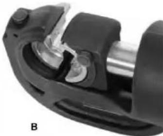
natural_image
Close-up of a mechanical assembly with black components and a metallic shaft (no visible text or symbols)Figur 2 – A. Matriser inriktade B. Formar feljusterade
natural_image
Close-up of a mechanical clamp or lever component with labeled parts (1 and 2), no readable text or symbols beyond labelsnatural_image
Close-up of a mechanical tool with metal clamping and a black handle (no visible text or symbols)Figur 4 Justera kontakten
natural_image
Close-up of hands using a crimping tool to handle a cylindrical component (no visible text or symbols)natural_image
Close-up of a mechanical component with a cylindrical shaft and flange, showing internal components and a labeled part '1' (no text or symbols beyond label)text_image
Labeled diagram of a mechanical tool kit with numbered parts for identification1- Dupper formhuvud
2- Tryckmatris
3- Bottenformsbas
natural_image
Assorted mechanical tools including a crimping tool, a black plastic case, and multiple black cylindrical components (no text or symbols visible)natural_image
Close-up of a hand holding a cylindrical mechanical tool with a handle, showing internal components and an arrow indicating motion (no text or symbols visible)Figura 1 Suporte de matriz totalmente retrátil
natural_image
Close-up of a mechanical component with labeled parts (1 and A), no readable text or symbols beyond labels
natural_image
Close-up of a mechanical assembly with black components and metallic shaft (no visible text or symbols)natural_image
Mechanical component diagram showing a clamp or bracket with labeled parts (1 and 2), no readable text or symbols beyond labels.natural_image
Close-up of a mechanical tool with a black handle and metallic components (no visible text or symbols)natural_image
Close-up of hands using a manual crimping tool to handle a cylindrical component (no text or symbols visible)natural_image
Close-up of a mechanical assembly with a cylindrical component and a rod inserted, labeled with number 1 (no text or symbols on the object itself)text_image
Labeled diagram of a mechanical tool kit with numbered parts for identificationnatural_image
Assorted mechanical tools including a crimping tool, black case, and multiple cylindrical components (no text or symbols visible)natural_image
Close-up of a hand holding a cylindrical mechanical tool with a black handle and arrow indicating direction (no text or symbols visible)natural_image
Close-up of a mechanical component with labeled parts (1 and A), no readable text or symbols beyond labels
natural_image
Close-up of a mechanical assembly with a metallic shaft and housing (no visible text or symbols)natural_image
Close-up of a mechanical clamp or connector with labeled parts (1 and 2), no visible text or symbols beyond labelsSK
natural_image
Close-up of hands using a crimping tool to handle a cylindrical component (no visible text or symbols)natural_image
Close-up of a mechanical assembly with a cylindrical component and a rod inserted, labeled with number 1 (no text or symbols on the main subject)text_image
Labeled diagram of a mechanical tool kit with numbered parts for identification1- Dupperova hlava
2- Lisovacie matrice
natural_image
Assorted mechanical tools including a crimping tool, a black toolbox, and multiple black cylindrical components (no text or symbols visible)natural_image
Close-up of a hand holding a cylindrical mechanical tool with a handle and arrow indicator (no visible text or symbols)natural_image
Close-up of a mechanical component with labeled parts (1 and A), no readable text or symbols beyond labels
natural_image
Close-up of a mechanical component with no visible text or symbolsnatural_image
Mechanical component diagram showing a clamp or lever mechanism with labeled parts (1 and 2), no readable text or symbols beyond labels.natural_image
Close-up of a mechanical clamp or tool with black and metallic components (no visible text or symbols)natural_image
Close-up of hands using a crimping tool to handle a cylindrical component (no visible text or symbols)natural_image
Close-up of a mechanical assembly with a cylindrical component and a rod inserted, labeled with number 1 (no text or symbols on the object itself)text_image
Labeled diagram of a mechanical tool kit with numbered parts for identificationnatural_image
Assorted mechanical tool including a crimping tool, a black hard case, and multiple black cylindrical components (no text or symbols visible)natural_image
Close-up of a hand holding a cylindrical mechanical tool with a black handle and labeled component (no text or symbols visible)natural_image
Close-up of a mechanical component with labeled parts (1 and A), no readable text or symbols beyond labels
natural_image
Close-up of a mechanical assembly with a metallic cylindrical component and black housing (no visible text or symbols)natural_image
Mechanical component diagram showing a lever handle and clamp mechanism (no text or symbols)natural_image
Close-up of a mechanical tool with a black handle and metal bracket (no visible text or symbols)natural_image
Close-up of hands using a crimping tool to handle a cylindrical component (no visible text or symbols)natural_image
Close-up of a mechanical component with a cylindrical shaft and bearing, showing no visible text or symbols.text_image
Labeled diagram of a mechanical tool kit with numbered parts for identification1- Κεφάλι Dupper
natural_image
Assorted mechanical tool including a crimping tool, a black hard case, and multiple cylindrical components (no text or symbols visible)natural_image
Close-up of a hand holding a cylindrical mechanical tool with a handle, showing internal components and an arrow indicating motion (no text or symbols visible)Slika 1 Potpuno uvlačeći držač matrice
1- Otpustite polugu

natural_image
Close-up of a mechanical component with labeled parts (1 and A), no readable text or symbols beyond labels
natural_image
Close-up of a mechanical assembly with a cylindrical component and a metallic shaft (no visible text or symbols)Slika 2 – A. Matrice poravnate B. Matrice neporavnate
1- Gumbi za otpuš tanje matrice
Pritisnite gumbe za otpuštanje matrice kako biste omogućili da matrice klize bočno unutra i iz držača matrice. Nemojte silom gurati matrice u držače matrica. Matrice bi trebale čvrsto i sigurno pristajati, a profili savijanja trebali bi biti poravnati (slika 2). Matrice se ne bi trebale pomicati osim ako je gumb za otpuštanje matrice pritisnut. Uvijek koristite odgovarajući set matrica. Ako postoje bilo kakvi problemi u vezi s pravilnim pristajanjem kalupa, nemojte koristiti alat. Ne koristite alat bez instaliranih matrica.
5. Uklanjanje/postavljanje postolja za prešanje glave.
Kada radite s alatom za savijanje na tlu, stalak za glavu za savijanje može se koristiti za podupiranje i stabilizaciju alata za savijanje.
natural_image
Mechanical component diagram showing a clamp or lever mechanism with labeled parts (1 and 2), no readable text or symbols beyond labels.natural_image
Close-up of a mechanical clamp or tool with metal components and a black handle (no visible text or symbols)Slika 4 Poravnavanje konektora
natural_image
Close-up of hands using a crimping tool to handle a cylindrical component (no visible text or symbols)natural_image
Close-up of a mechanical assembly with a cylindrical component and a rod inserted, labeled with number 1 (no text or symbols on the object itself)text_image
Labeled diagram of a mechanical tool kit with numbered parts for identification1- Dupper rezna glava
2- Prešanje umire
3- Donja baza matrice
4- Donja glava alata
5- Zasun za glavu
6- Baza ručke
natural_image
Assorted mechanical tool including a crimping tool, plastic housing, and multiple black cylindrical components (no text or symbols visible)natural_image
Close-up of a hand holding a cylindrical mechanical tool with a handle and labeled component (no text or symbols visible)natural_image
Close-up of a mechanical component with labeled parts (1 and A), no readable text or symbols beyond labels
natural_image
Close-up of a mechanical assembly with a metallic shaft and internal components (no visible text or symbols)natural_image
Mechanical component diagram showing a clamp or lever mechanism with labeled parts (1 and 2), no readable text or symbols beyond labels.natural_image
Close-up of a mechanical clamp or tool with a black handle and metallic components (no visible text or symbols)natural_image
Close-up of hands using a crimping tool to handle a cylindrical component (no visible text or symbols)natural_image
Close-up of a mechanical component with a cylindrical shaft and flange, showing internal components and a labeled part '1' (no text or symbols beyond label)text_image
Labeled diagram of a mechanical tool kit with numbered parts for identificationnatural_image
Assorted mechanical tools including a black hard case, crimping tool, and multiple cylindrical components (no text or symbols visible)natural_image
Close-up of a hand holding a cylindrical mechanical tool with a handle, showing internal components and an arrow indicating motion (no text or symbols visible)natural_image
Close-up of a mechanical component with labeled parts (1 and A), no readable text or symbols beyond labels
natural_image
Close-up of a mechanical component with a metallic shaft and black housing (no visible text or symbols)Figura 2 – A. matrite aliniate B. matrite nealiniate
1- Butoane de eliberare a matritei
natural_image
Close-up of a mechanical clamp or connector with labeled parts (1 and 2), no readable text or symbols beyond labelsnatural_image
Close-up of a mechanical clamp or tool with metal components and a black handle (no visible text or symbols)natural_image
Close-up of hands using a manual power crimping tool, no visible text or symbolsnatural_image
Close-up of a mechanical assembly with a cylindrical component and a rod inserted, labeled with number 1 (no text or symbols on the main subject)text_image
Labeled diagram of a mechanical tool kit with numbered parts for identification11- Comutator ON/OFF
12- Mâner solid
natural_image
Assorted mechanical tools including a crimping tool, black housing, and multiple cylindrical components (no text or symbols visible)natural_image
Close-up of a hand holding a cylindrical mechanical tool with a handle, showing internal components and an arrow indicating motion (no text or symbols visible)Slika 1 Popolnoma uvlečno držalo matrice
natural_image
Close-up of a mechanical component with labeled parts (1 and A), no readable text or symbols beyond labels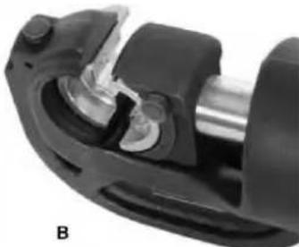
natural_image
Close-up of a mechanical assembly with a metallic cylindrical component and black housing (no visible text or symbols)Slika 2 – A. Matrice poravnane B. Matrice neporavnane
natural_image
Close-up of a mechanical clamp or lever component with labeled parts (1 and 2), no visible text or symbols beyond labels.natural_image
Close-up of a mechanical tool with black and metallic components, no visible text or symbolsnatural_image
Close-up of hands using a crimping tool to handle a cylindrical component (no text or symbols visible)natural_image
Close-up of a mechanical assembly with a cylindrical component and a rod inserted, no visible text or symbolstext_image
Labeled diagram of a mechanical tool kit with numbered parts for identification1- Dupper rezilna glava
2- Stiskanje umre
3- Spodnja osnova matrice
4- Spodnja glava orodja
5- Zapah glave