
SBBD-1250EC - Saw MSW - Free user manual and instructions
Find the device manual for free SBBD-1250EC MSW in PDF.

| Product type | Scroll saw with cardan shaft |
| Brand | MSW |
| Model | SBBD-1250EC |
| Rated voltage | 230 V ~ / 50 Hz |
| Rated power | 70 W (S1), 90 W (S2 30 min), 125 W (S2 5 min) |
| No-load speed | 550-1600 rpm (variable) |
| Maximum cutting height | 50 mm |
| Dimensions (L × W × H) | 630 × 340 × 370 mm |
| Weight | 10.6 kg |
| Tilting table | 0° to 45° with locking |
| Blade types | Pin-end blades, plain-end blades (side cutting) |
| Interior cutting | Possible (6 mm hole required) |
| Flexible shaft included | Yes, for use with routing bits |
| Dust extraction connection | Yes (removable dust cover) |
| On/off switch | With integrated speed control |
| Hold-down foot | Adjustable to hold the workpiece |
| Bearing lubrication | Every 10 hours (SAE 20 oil) |
| Safety guards | Blade guard, emergency stop (red button) |
| Included accessories | Blades, wrenches, adapters, blade length gauge |
| Spare parts | Available through MSW authorized service |
Frequently Asked Questions - SBBD-1250EC MSW
User questions about SBBD-1250EC MSW
0 question about this device. Answer the ones you know or ask your own.
Ask a new question about this device
Download the instructions for your Saw in PDF format for free! Find your manual SBBD-1250EC - MSW and take your electronic device back in hand. On this page are published all the documents necessary for the use of your device. SBBD-1250EC by MSW.
USER MANUAL SBBD-1250EC MSW
natural_image
Technical line drawing of a mechanical component with labeled part '1' (no text or symbols beyond label)natural_image
Line drawing of a manual machine with hands operating it, no text or symbols present1 - Klinge
2 - Quadratisch
natural_image
Line drawing of a sewing machine with a hand operating the base panel (no text or symbols present)natural_image
Line drawing of a hand using a tool to adjust or install a mechanical component, with no visible text or symbols.Abbildung C
natural_image
Line drawing of two hands using a tool to apply or install a package (no text or symbols present)Abbildung D
natural_image
Line drawing of two hands using a handheld tool to interact (no text or symbols present)Abbildung E
This User Manual has been translated using machine translation. We have made every effort to ensure the translation is accurate, but please note that automated translations are not perfect and are not meant to replace human translators. The official version of the User Manual is in English. Any differences between the translated version and the original English are not legally binding. If you have any questions about the accuracy of the translation, please refer to the English version, which is the official reference. More language versions are available upon request via info@expondo.com.
Technical data
| Parameter description Parameter value | |
| Product name | Scroll Saw with PTO Shaft |
| Model | MSW-SBBD-1250EC |
| Rated voltage [V~] / frequency [Hz] | 230 / 50 |
| Rated power [W] | 70W (S1), 90W (S2 30 min.), 125W(S2 5 min.) |
| No Load Speed [rpm] | 550-1600 |
| Max cutting height [mm] | 50 |
| Dimensions [width x depth x height; mm] | 630 x 340 x 370 |
| Weight [kg] | 10.6 |
WARNING: Read and understand all instructions. Failure to follow all instructions listed below may result in electric shock, fire and/or serious personal injury.
READ ALL INSTRUCTIONS
Read the operator's manual carefully. Lear the applications and limitations as well as specific potential hazards related to this tool.
GUARD AGAINST ELECTRICAL SHOCK BY PREVENTING BODY CONTACT WITH GROUNDED SURFACES
For example: pipes, radiators, refrigerators.
KEEP GUARDS IN PLACE and in working order.
REMOVE ADJUSTING KEYS AND WRENCHES
Form a habit of checking to see keys and adjusting wrenches are removed from the tool before turning it on.
KEEP THE WORK AREA CLEAN
Cluttered work areas and work benches invite accidents. DO NOT leave tools or pieces of wood on the tool while it is in operation.
DO NOT USE IN DANGEROUS ENVIRONMENTS
DO NOT use power tools in damp or wet locations or expose them to rain. Keep the work area well lit.
KEEP CHILDREN AND VISITORS AWAY
All visitors should wear safety glasses and be kept a safe distance from work area. Do not let visitors contact tools or extension cords while operating.
MAKE WORKSHOPS CHILDPROOF
By removing switch keys, unplugging tools electrical receptacles, and using padlocks.
DON'T FORCE THE TOOL
It will do the job better and safer at the rate for which it was designed.
USE THE RIGHT TOOL
DO NOT force the tool or attachment to do a job for which it was not designed.
USE THE PROPER EXTENSION CORD
Make sure your extension cord is in good condition.
Use only a cord heavy enough to carry the current your product will draw
KEEP BLADES CLEAN, SHARP
Sharp blades minimize stalling and kickback.
DRESS APPROPRIATELY
DO NOT wear loose clothing, neckties, or jewellery that can get caught and draw you into moving parts. Rubber gloves and nonslip footwear are recommended when working outdoors. Also wear protective hair covering to contain long hair.
ALWAYS WEAR SAFETY GLASSES WITH SIDE SHIELDS
Everyday eyeglasses have only impact-resistant lenses, they are NOT safety glasses.
SECURE WORK
Use clamps or a vice to hold work when practical, it is safer than using your hand and frees both hands to operate the tool.
DO NOT OVERREACH
Keep proper footing and balance at all times.
MAINTAIN TOOLS WITH CARE
Always keep tools clean and in good working order. Keep all blades and tool bits sharp, dress grinding wheels and change other abrasive accessories when worn.
DISCONNECT TOOLS
When not in use, before servicing, or when changing attachments, blades, bits, cutters, etc., all tools should be disconnected from the power supply.
AVOID ACCIDENTAL STARTING
Always check that the switch is off before plugging any power tool into a power source. USE RECOMMENDED ACCESSORIES
The use of incorrect or improper accessories may result in injury to the operator or damage to the tool.
Serious injury could occur if the tool is tipped.
CHECK DAMAGED PARTS
Before further use of the tool, a guard or other part that is damaged should be carefully checked to determine that it will operate properly and perform its intended function. Check for alignment of moving parts, binding of moving parts, breakage of parts, mounting and any other conditions that may affect its operation. A guard or other part that is damaged must be properly repaired or replaced by an authorised service centre to avoid risk of personal injury.
USE THE RIGHT DIRECTION OF FEED
Feed work into a blade, cutter, or sanding spindle against the direction or rotation of the blade, cutter, or sanding spindle only.
Never leave the tool unattended complete stop.
PROTECT YOUR LUNGS
Always wear a face or dust mask to prevent inhaling dangerous dust or airborne particles including wood dust, silica dust, and asbestos dust. Direct particles away from face and body. Always operate tool in well ventilated area and provide for proper dust removal. Use a dust collection system wherever possible. Exposure to the dust may cause serious and permanent respiratory or other injury, including silicosis (a serious lung disease), cancer, and death.
Avoid breathing the dust, and avoid prolonged contact with dust. Allowing dust to get into your mouth or eyes or lay on your skin may promote absorption of harmful material. Always use properly fitting approved respiratory protection appropriate for the dust exposure, and wash exposed areas with soap and water.
PROTECT YOUR HEARING
Wear hearing protection during extended operation.
DO NOT DAMAGE THE POWER CORD
Never carry a tool by the cord or yank it to disconnect it from the receptacle. Keep cord away from heat, oil, and sharp edges.
USE OUTDOOR EXTENSION CORDS
When the tool is used outdoors, use only extension cords with approved ground connection that are intended for use outdoors and so marked.
NEVER USE IN AN EXPLOSIVE ATMOSPHERE
Normal sparking of the motor could ignite fumes, gases and flammable liquids.
INSPECT TOOL CORDS PERIODICALLY
If damaged, have repaired by a qualified service technician at an authorised service facility. Repair or replace a damaged or worn cord immediately. Stay constantly aware of cord location and keep it well away from the rotating blades and parts.
INSPECT EXTENSION CORDS PERIODICALLY
Replace if damaged.
KEEP TOOL DRY, CLEAN, AND FREE FROM OIL AND GREASE
Always use a clean cloth when cleaning. Never use brake fluids, gasoline, petroleum-based products, or any solvents to clean the tool.
STAY ALERT AND EXERCISE CONTROL
Watch what you are doing and use common sense. DO NOT operate the tool when you are tired. DO NOT rush.
DO NOT USE TOOL IF SWITCH DOES NOT TURN IT ON AND OFF
Have defective switches replaced by an authorised service centre.
INSPECT FOR AND REMOVE ALL NAILS FROM LUMBER BEFORE USING THIS TOOL
Following this rule will reduce the risk of serious personal injury.
NEVER START A TOOL WHEN ANY ROTATING COMPONENT IS IN CONTACT WITH THE WORKPIECE
DO NOT OPERATE A TOOL WHILE UNDER THE INFLUENCE OF DRUGS, ALCOHOL, OR ANY MEDICATION!
WHEN SERVICING
Use only identical replacement parts. Use of any other parts may create a hazard or cause product damage.
DOUBLE CHECK ALL SETUPS
Make sure the tool assembly is tight and not making contact with the workpiece before connecting to power supply.
DO NOT touch the blade with your fingers or any other body part whilst the scroll saw is plugged in and/or powered On (1).
DO NOT leave the scroll saw unattended when plugged in or powered On (1).
DO NOT touch the carving burr or the flexi-shaft cable with your fingers or any other body part when the flexi- shaft is installed on the saw.
DO NOT change the blade of the saw whilst it is plugged in or powered On (1). Always unplug the scroll saw before changing the blade.
DO NOT change carving burr whilst the scroll saw is plugged in or powered On (I). Always unplug the scroll saw before changing burr.
SAVE THESE INSTRUCTIONS
Refer to them frequently and use them to instruct others who may use this tool. If you loan someone this tool, loan these instructions also.
WARNING
Some dust created by power sanding, sawing, grinding, drilling, and other construction activities contains chemicals known to cause cancer; birth defects or other reproductive harm. Some examples of these chemicals are:
- lead from lead-based paints,
• crystalline silica from bricks and cement and other masonry products, and
• arsenic and chromium from chemically-treated lumber.
Your risk from these exposures varies, depending on how often you do this type of work. To reduce your exposure to these chemicals: work in a well ventilated area with approved safety equipment.
ASSEMBLY
Installing Pin Blades
* Ensure the blade teeth are pointing down
-
Lower the blade down through the access hole in the tilting table top.
-
Hook the blade pin into the pin recess on the lower blade holder. For boards over 405mm length, install the blade with the teeth sideways using the sideways recess. This will turn the saw into a 'Bandsaw'
-
Apply slight downwards pressure onto the upper blade holder and hook the blade into the pin recess. Release the pressure.
-
Tighten the blade using the blade tension knob to eliminate any slack in the blade. Turn the blade tension knob one full clockwise turn until all slack is removed.
-
Blade positioned for front cutting
-
Blade positioned for side cutting
-
Blade pin
-
Adaptor guard
-
Cap screw
-
Blade slots
-
Arm
-
Blade tension knob
-
Loosen
-
Tighten
-
Lower inner holder
-
Table tilted for picture clarity
-
Upper inner blade holder
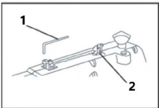
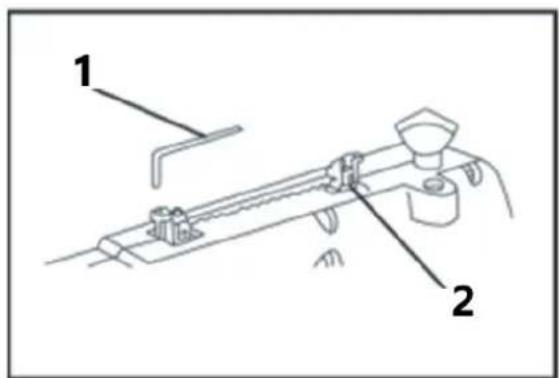
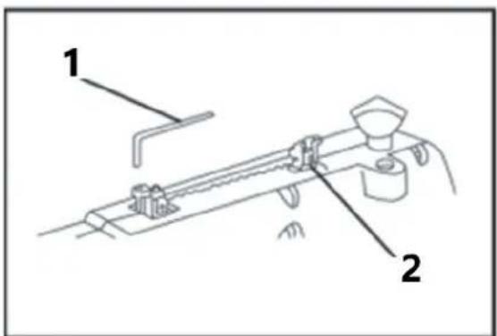
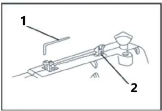
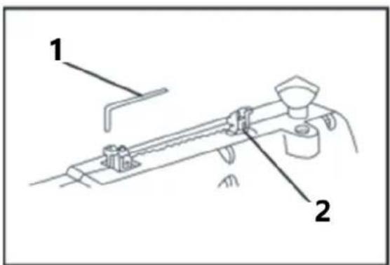
Installing Plain-End Blades (Sideways Cutting)
* Ensure the blade teeth are pointing down
-
Adjust one set screw on each adaptor until it covers approximately half the hole.
-
Loosen the other set screw on each adaptor and slide one adaptor onto each end of the blade. (Figure A below).
-
Place the adaptors into the mould on the scroll saw arm and adjust the blade length using the blade length gauge. (Figure B below).
- Secure the second set screw on each adaptor the lock the blade in place.
- Rotate the blade tension knob anti-clockwise to release the tension.
- Lower the bottom adaptor through the access hole in the table top. Hook the lower adaptor onto the outer section of the lower blade holder.
- Slide the top adaptor onto the pin recess between the adaptor guard and the outer section of the upper blade holder.
- Tighten the blade tension knob one full clockwise turn and remove all slack.
- Blade pin
- Pin recesses
- Arm
- Blade length gauge
- Blade adaptor
- Loosen
- Lower inner blade holder
-
Upper inner blade holder
-
Adaptor guard
- Cap screw
- Slight pressure here
- Blade
- Blade tension knob
- Tighten
- Table tilted for picture clarity
natural_image
Technical line drawing of a mechanical assembly with labeled component '1' (no text or symbols beyond label)Figure A
1 - Blade
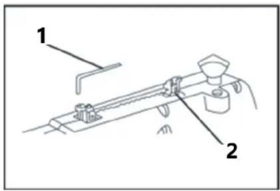
Figure B
1-Wrench
2 - Blade length gauge
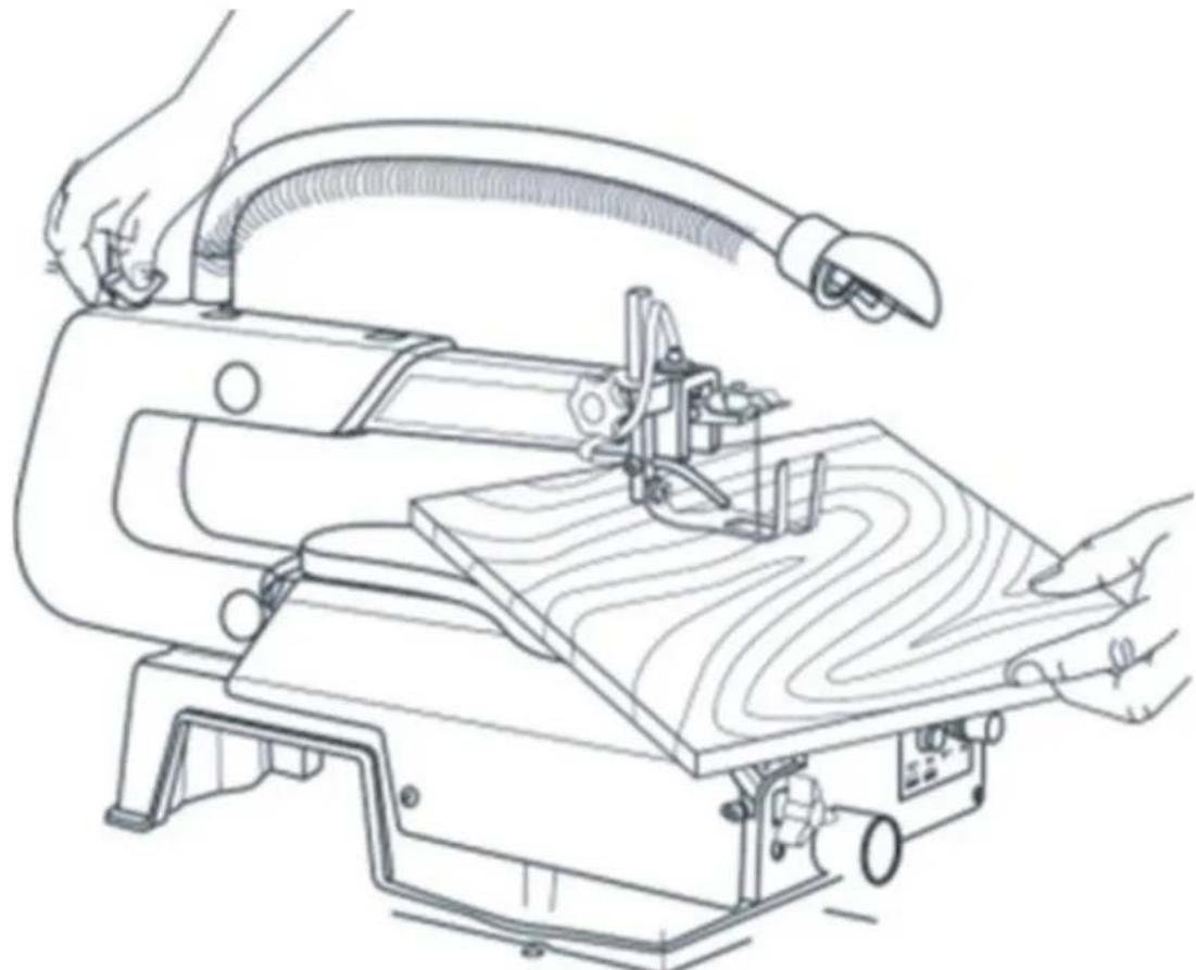
Making an Interior Scroll Cut
natural_image
Line drawing of a manual wood cutting machine with hands operating it (no text or symbols present)One of the features of this saw is that it can be used to make scroll cuts on the inside surface area of a board without breaking or cutting through the edge of the workpiece.
- Drill a 6mm hole in the centre of your workpiece.
- Place the workpiece onto the scroll saw and align the new hole with the easy access hole in the table top.
- Insert the blade through the new hole in your workpiece.
- Lower the drop foot until it rests just on top of your workpiece and begin work.
- Once the work is finished, remove the blades before moving the workpiece.
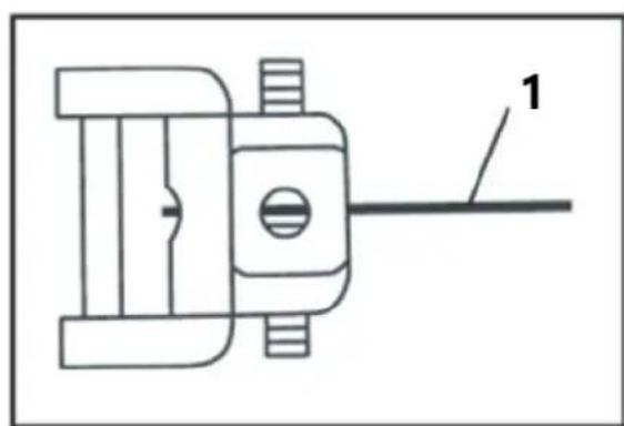
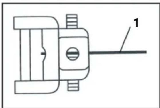
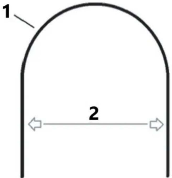
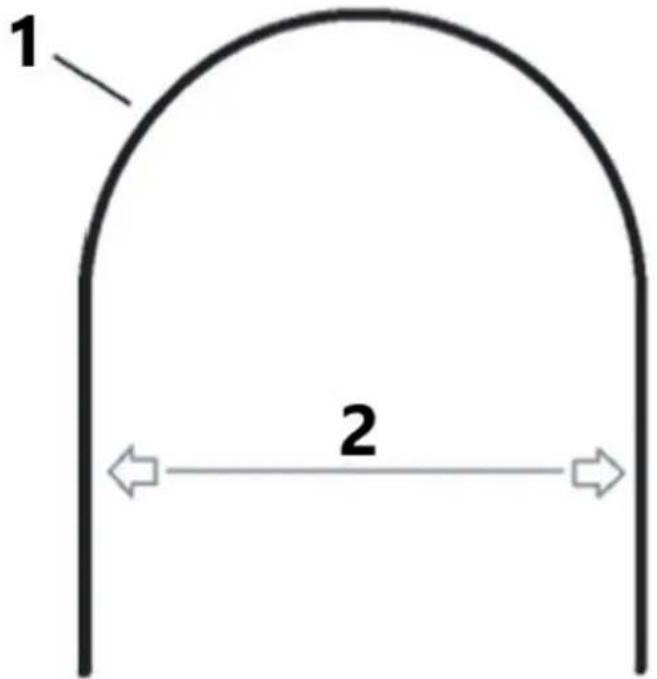
Making Angled Cuts
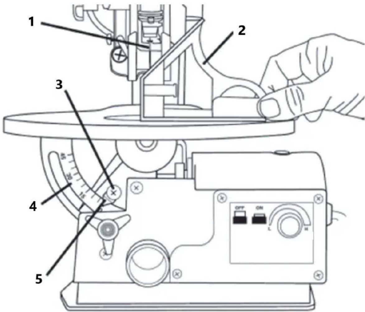
1 - Blade
2-Square
3 - Pointer adjustment screw
4 - Degree scale
5 - Pointer
- Loosen the locking knob so that the table can be tilted between angles 0-45°
- Using the degree scale, determine the angle which you would like to table to be set at.
- Tighten the locking knob to secure the table and the desired angle.
- Adjust the drop foot so that it is parallel to the table top.
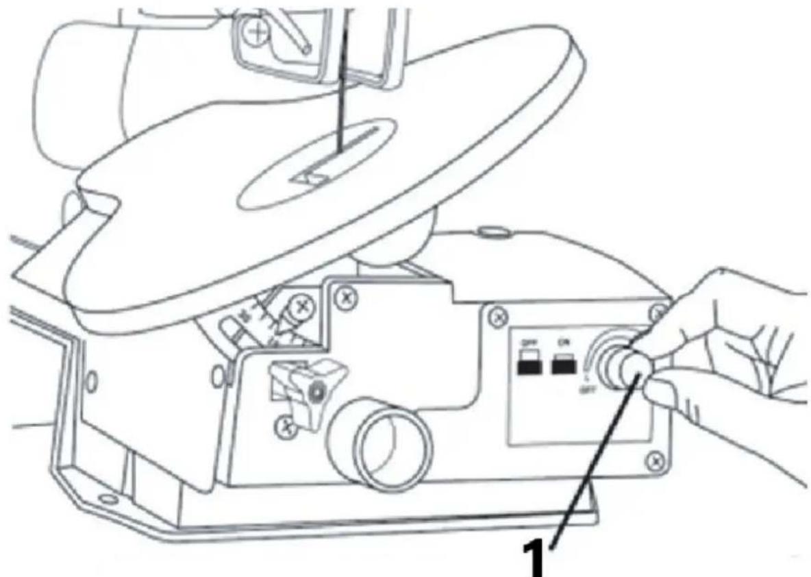
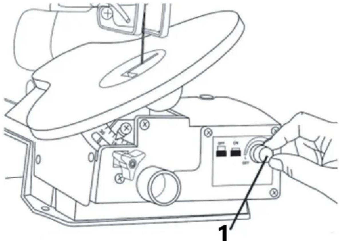
Turning the Scroll Saw On
natural_image
Line drawing of a sewing machine with a hand operating the base panel (no text or symbols present)1 - ON/OFF and variable speed switch
- Press the green On (I) button to power the sander. Press the red Off (0) button to turn it off.
- When using the variable speed dial, wait for the speed to level before use.
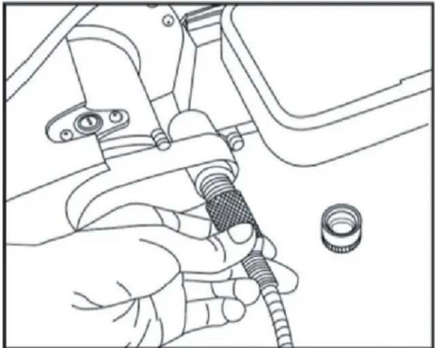
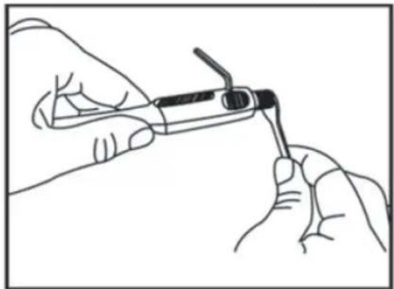
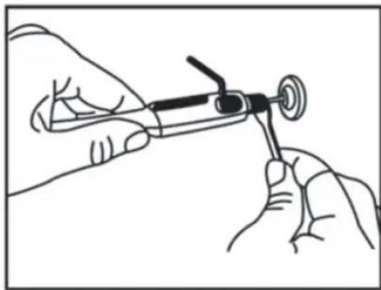
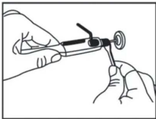
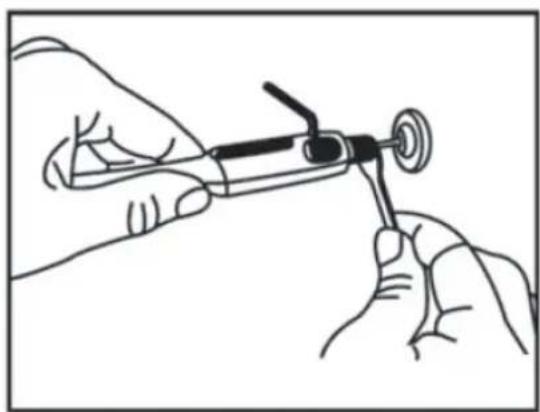
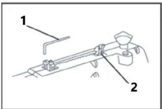
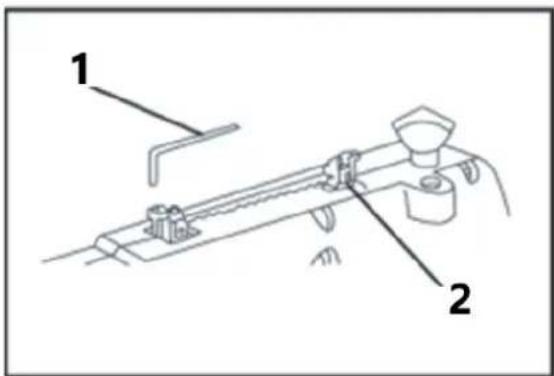
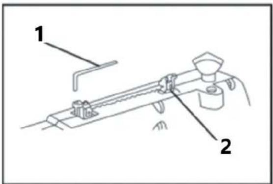
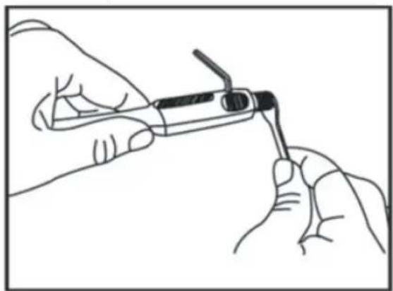
Installing the Flexi-shaft & Carving Burrs
natural_image
Line drawing of a hand using a tool to adjust or install a mechanical component, with no visible text or symbols.Figure C
- Turn the scroll saw Off (0) and unplug it from the mains power.
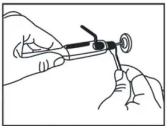
- Remove the dust cover and screw on the flexi-shaft (Figure C above).
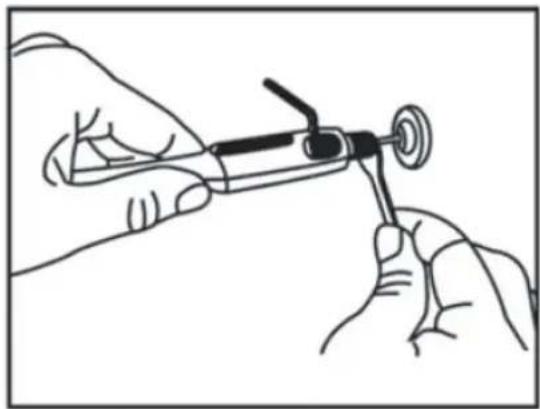
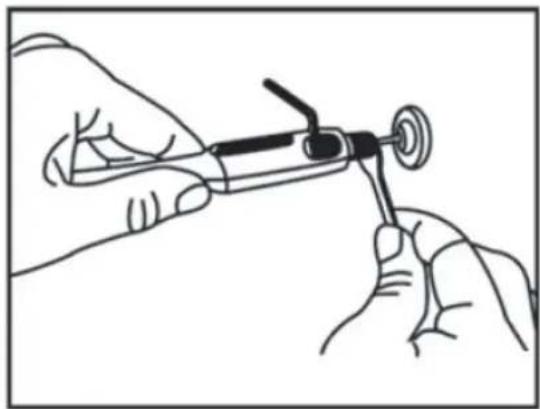
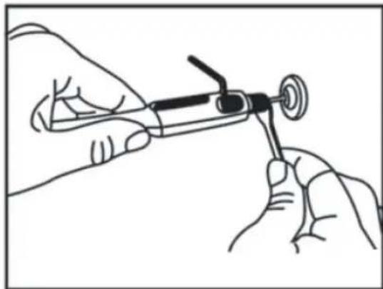
- Insert the Allen key in the hole of the handpiece to stop the shaft rotating.
- Loosen the collet nut using the wrench provided (Figure D below).
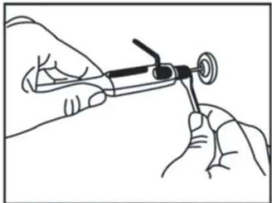
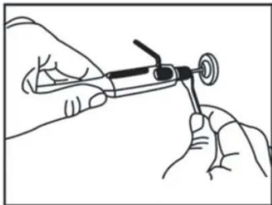
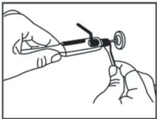
- Insert your selected carving burr into the handpiece and tighten the collet nut using the wrench (Figure E below).
- Remove the wrench from the handpiece.
natural_image
Line drawing of two hands using a tool to apply or install a package (no text or symbols present)Figure D
natural_image
Line drawing of two hands holding a syringe and a tool, no text or symbols presentFigure E
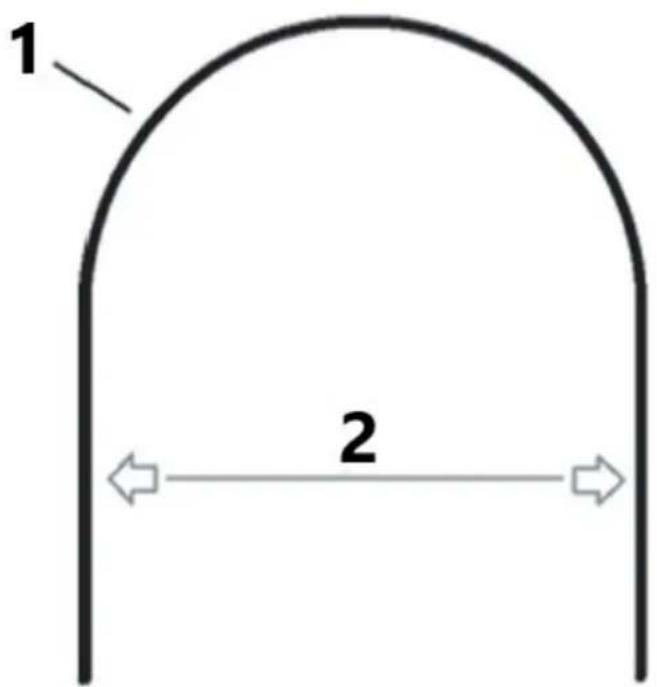
Using the Flexi-shaft

1 - Flexi shaft cable
2-7" / 178mm
Follow these guidelines when operating the flexi-shaft accessory to prevent the inner cable from snapping.
- It is advised to secure the workpiece in place before using the flexi-shaft
- Do not force the carving burr into the workpiece as it will stall the inner cable of the flexi-shaft and snap. Allow the carving burr to cut the workpiece naturally.
- Allow the speed of the shaft to level before engaging your workpiece. If the flexi-shaft is rotating too slowly it will get stuck in the workpiece and the
-
inner cable will snap Move the handpiece in a slow, smooth motion. 'Scribbling' in the wood will cause the burr to get stuck and snap the inner cable.
-
Do not bend the flexi-shaft past a bend radius of 7".
- If the flexi-shaft is bent beyond this radius the inner cable will not be able to rotate and will snap.
Maintenance
Daily Tasks:
- Use a vacuum or air-line to remove dust or debris from the saw after each use. Leaving dust on the scroll saw can cause the motor to stop working and may lead to rust on the table surface.
-
Lubricate the arm bearings after every 10 hours of saw usage. Perform a re-lubrication after 50 hours of use or if you hear a 'squeaking' noise. Follow these steps to lubricate the bearings:
-
Tilt the saw on its side.
- Apply a generous amount of SAE 20 oil around the shaft and bronze bearing.
- Let the oil soak in overnight with the saw still on its side.
- Repeat the above steps for the opposite side of the saw the next day.
| Problem | Possible Cause | Suggested Action |
| Blades keep breaking | 1. Incorrect tension | 1. Adjust blade tension using the blade tension knob. |
| 2. Overworking the blade | 2. Decrease feed rate. | |
| 3. Improper blade usage | 3. Use narrow blades for softwoods and thicker blades for hardwoods. | |
| 4. Twisting blade in wood | 4. Ensure the workpiece is fed straight without applying sideways pressure. | |
| 5. Incorrect TPI (teeth per inch) blade | 5. Install the correct blade. | |
| Vibration(It is normal for this saw to vibrate slightly. Use this guide if vibration has worsened since new.) | 1. Improper mounting | 1. Add padding between the saw base and the workbench. |
| 2. Inadequate mounting surface | 2. Mount the saw on a sturdier workbench. | |
| 3. Loose mounting | 3. Tighten the mounting bolts. | |
| 4. Loose motor | 4. Tighten motor mounting screws. | |
| Blade runout(Blade not in line with arm motion) | 1. Misaligned blade holders | 1. Loosen the cap screws holding the blade to the upper and lower arms. Adjust the blade position and re-tighten the cap screws. |

USUŃ KLUCZE REGULACYJNE I KLUCZE NAKRĘTNE
natural_image
Technical line drawing of a mechanical assembly with labeled component '1' (no text or symbols beyond label)natural_image
Line drawing of a manual wood cutting machine with hands operating it (no text or symbols present)natural_image
Line drawing of a sewing machine with a hand operating the base panel (no text or symbols present)natural_image
Line drawing of a hand using a tool to adjust or install a mechanical component, with no visible text or symbols.Rysunek C
natural_image
Line drawing of two hands holding a pen or tool, no text or symbols presentRysunek D
natural_image
Line drawing of two hands holding a medical or laboratory instrument (no text or symbols visible)Rysunek E
USCHOVEJTE TYTO POKYNY
natural_image
Technical line drawing of a mechanical assembly with labeled component '1' (no text or symbols beyond label)Obrázek A
1 – Čepel

natural_image
Line drawing of a manual wood cutting machine with hands operating it (no text or symbols present)1 – Čepel
2 – čtverec
natural_image
Line drawing of a hand using a tool to adjust or install a mechanical component, with no visible text or symbols.Obrázek C
natural_image
Line drawing of two hands using a tool to apply or install a pen (no text or symbols present)Obrázek D
natural_image
Line drawing of two hands holding a syringe and a mechanical component (no text or symbols)Obrázek E
natural_image
Technical line drawing of a mechanical assembly with labeled component '1' (no text or symbols beyond label)Figure A
1 - Lame
natural_image
Line drawing of a manual machine with hands operating it, no text or symbols presentnatural_image
Line drawing of a sewing machine with a hand operating the base panel (no text or symbols present)natural_image
Line drawing of a hand using a tool to adjust or install a mechanical component, with no visible text or symbols.Figure C
natural_image
Line drawing of two hands holding a pen or tool, no text or symbols presentFigure D

natural_image
Line drawing of two hands holding a medical or laboratory instrument (no text or symbols visible)Figure E
natural_image
Technical line drawing of a mechanical component with labeled part '1' (no text or symbols beyond label)Figura A
1 - Lama
natural_image
Line drawing of a manual wood cutting machine with hands operating it (no text or symbols present)natural_image
Line drawing of a sewing machine with a hand operating the base panel (no text or symbols present)natural_image
Line drawing of a hand using a tool to adjust or install a mechanical component, with no visible text or symbols.Figura C
natural_image
Line drawing of two hands holding a pen or tool, no text or symbols presentFigura D

natural_image
Line drawing of two hands holding a medical or laboratory instrument (no text or symbols visible)Figura E
natural_image
Technical line drawing of a mechanical component with labeled part '1' (no text or symbols beyond label)Figura A
1 - Cuchilla
natural_image
Line drawing of a manual machine with hands operating it, no text or symbols presentnatural_image
Line drawing of a hand using a tool to adjust or install a mechanical component, with no visible text or symbols.Figura C
natural_image
Line drawing of two hands holding a tool, no text or symbols presentFigura D

natural_image
Line drawing of two hands holding a syringe or tool, no text or symbols presentFigura E
natural_image
Technical line drawing of a mechanical component with labeled part '1' (no text or symbols beyond label)A ábra
1 - Penge

natural_image
Line drawing of a manual wood cutting machine with hands operating it (no text or symbols present)1 - Penge
2 - Négyzet
natural_image
Line drawing of a hand using a tool to adjust or install a mechanical component, with no visible text or symbols.Cábra
natural_image
Line drawing of two hands holding a tool, no text or symbols presentD ábra
natural_image
Line drawing of two hands holding a syringe or tool, no text or symbols presentE ábra
HOLD ARBEJDSOMRÅDET RENT
HOLD KNIVENE RENE OG SKARPE
natural_image
Technical line drawing of a mechanical assembly with labeled component '1' (no text or symbols beyond label)Figur A
1 - Blad

natural_image
Line drawing of a manual wood cutting machine with hands operating it (no text or symbols present)1 - Blad
2 - Firkantet
natural_image
Line drawing of a sewing machine with a hand operating the base panel (no text or symbols present)natural_image
Line drawing of a hand using a tool to adjust or install a mechanical component, with no visible text or symbols.Figur C
natural_image
Line drawing of two hands using a tool to apply or install a pen (no text or symbols present)Figur D

natural_image
Line drawing of two hands holding a medical or laboratory instrument (no text or symbols visible)Figur E
natural_image
Technical line drawing of a mechanical component with labeled part '1' (no text or symbols beyond label)Kuva A
1 - Terä
natural_image
Line drawing of a manual wood cutting machine with hands operating it (no text or symbols)natural_image
Line drawing of a sewing machine with a hand operating the base panel (no text or symbols present)natural_image
Line drawing of a hand using a tool to adjust or install a mechanical component, with no visible text or symbols.Kuva C
natural_image
Line drawing of two hands holding a pen or tool, no text or symbols presentKuva D
natural_image
Line drawing of two hands holding a medical or laboratory instrument (no text or symbols present)Kuva E
natural_image
Technical line drawing of a mechanical component with labeled part '1' (no text or symbols beyond label)Figuur A
1 - Blad
natural_image
Line drawing of a manual machine with hands operating it, no text or symbols presentnatural_image
Line drawing of a sewing machine with a hand operating the base panel (no text or symbols present)natural_image
Line drawing of a hand using a tool to adjust or install a mechanical component, with no visible text or symbols.Figuur C
natural_image
Line drawing of two hands holding a pen or tool, no text or symbols presentFiguur D
natural_image
Line drawing of two hands holding a medical or laboratory instrument (no text or symbols visible)Figuur E
KJENN DITT ELEKTROVERKT∅Y
HOLD ARBEIDSOMRÅDET RENT
Rotete arbeidsområder og arbeidsbenker inviterer til ulykker. IKKE la verktøy eller trebiter ligge på verktøyet mens det er i drift.
IKKE BRUK I FARLIGE MILJ∅ER
HOLD KNIVENE RENE, SKARPE
VEDLIKEHOLD VERKT∅Y MED FORSIKTIGHET
HOLD VERKT∅Y T∅RT, RENT OG FRI FOR OLJE OG FETT
- Bladstift
- Pinneutsparinger
- Væpne
- Bladlengdemåler
- Bladadapter
- Løsne
- Nedre indre bladholder
-
∅vre indre bladholder
-
Adapterbeskyttelse
- Toppskrue
- Litt press her
- Blad
- Knivspenningsknapp
- Stramme
- Bord vippet for klarhet i bildet
natural_image
Technical line drawing of a mechanical component with labeled part '1' (no text or symbols beyond label)Figur A
1 - Blad
natural_image
Line drawing of a manual wood cutting machine with hands operating it (no text or symbols present)1 - Blad
2 - Firkantet
3 – Pekerjusteringsskrue
4 - Gradskala
5 - Peker
natural_image
Line drawing of a hand using a tool to adjust or install a mechanical component, with no visible text or symbols.Figur C
natural_image
Line drawing of two hands holding a tool, no text or symbols presentFigur D
natural_image
Line drawing of two hands holding a syringe or tool, no text or symbols presentFigur E
natural_image
Technical line drawing of a mechanical component with labeled part '1' (no text or symbols beyond label)Bild A
1 - Blad

natural_image
Line drawing of a manual wood cutting machine with hands operating it (no text or symbols present)1 - Blad
2 - Fyrkant
3 – Pekarens justeringsskruv
4 - Gradskala
5 - Pekare
natural_image
Line drawing of a sewing machine with a hand operating the base panel (no text or symbols present)natural_image
Line drawing of a hand using a tool to adjust or install a mechanical component, with no visible text or symbols.Bild C
natural_image
Line drawing of two hands holding a pen or tool, no text or symbols presentBild D

natural_image
Line drawing of two hands holding a medical or laboratory instrument (no text or symbols visible)Bild E
natural_image
Technical line drawing of a mechanical component with labeled part '1' (no text or symbols beyond label)Figura A 1 – Lâmina
natural_image
Line drawing of a manual machine with hands operating it, no text or symbols presentnatural_image
Line drawing of a hand using a tool to adjust or install a mechanical component, with no visible text or symbols.Figura C
natural_image
Line drawing of two hands holding a tool, no text or symbols presentFigura D

natural_image
Line drawing of two hands holding a syringe or tool, no text or symbols presentFigura E
Usando o Flexi-shaft
USCHOVAJTE TIETO POKYNY
natural_image
Technical line drawing of a mechanical assembly with labeled component '1' (no text or symbols beyond label)natural_image
Line drawing of a hand operating a wooden board machine with a curved handle (no text or symbols)1 – Čepel'
2 – štvorec
3 – Nastavovacia skrutka ukazovatel'a
4 – stupňová stupnica
5 - Ukazovatel'
natural_image
Line drawing of a sewing machine with a hand operating the base panel (no text or symbols present)1 – ON/OFF a spínač s premenlivou rýchlostou
natural_image
Line drawing of a hand using a tool to adjust or install a mechanical component, with no visible text or symbols.Obrázok C
natural_image
Line drawing of two hands using a tool to apply or install a package (no text or symbols present)Obrázok D

natural_image
Line drawing of two hands holding a syringe and a tool, no text or symbols presentObrázok E
natural_image
Technical line drawing of a mechanical component with labeled part '1' (no text or symbols beyond label)Фигура А
1 – Острие
natural_image
Line drawing of a manual wood cutting machine with hands operating it (no text or symbols present)1 - Острие
2 – Квадрат
natural_image
Line drawing of a sewing machine with a hand operating the base panel (no text or symbols present)natural_image
Line drawing of a hand using a tool to adjust or install a mechanical component, with no visible text or symbols.Фигура С
natural_image
Line drawing of two hands using a tool to apply or install a pen (no text or symbols present)Фигура Г
natural_image
Line drawing of two hands holding a medical or laboratory instrument (no text or symbols present)Фигура Е
natural_image
Technical line drawing of a mechanical assembly with labeled component '1' (no text or symbols beyond label)Εικόνα Α
1 - Λεπίδα

natural_image
Line drawing of a manual wood cutting machine with hands operating it (no text or symbols present)1 - Λεπίδα
2 – Τετράγωνο
natural_image
Line drawing of a sewing machine with a hand operating the base panel (no text or symbols present)natural_image
Line drawing of a hand using a tool to adjust or install a mechanical component, with no visible text or symbols.Εικόνα Γ
natural_image
Line drawing of two hands using a tool to apply or install a pen (no text or symbols present)Εικόνα Δ
natural_image
Line drawing of two hands holding a handheld device with a circular connector (no text or symbols)Εικόνα Ε
-
Nož postavljen za prednje rezanje
-
Zatik oštrice
-
Vijak s poklopcem
-
Ruka
-
Olabaviti
-
Donji unutarnji držač
-
Gornji unutarnji držač oštrice
-
Nož postavljen za bočno rezanje
-
Štitnik adaptera
-
Utori za oštrice
-
Gumb za zatezanje oštrice
-
Zategnite
-
Stol nagnut radi jasnoće slike
Ugradnja oštrica s ravnim krajem (bočno rezanje)
natural_image
Technical line drawing of a mechanical assembly with labeled component '1' (no text or symbols beyond label)Slika A 1 – Oštrica
natural_image
Line drawing of a manual wood cutting machine with hands operating it (no text or symbols present)Jedna od značajki ove pile je da se njome mogu napraviti zavojni rezovi na unutarnjoj površini ploče bez lomljenja ili rezanja ruba izratka.
1 - Oštrica
2 - Trg
3 – Vijak za podešavanje kazaljke
4 – Skala stupnjeva
5 - Pokazivač
- Otpustite gumb za zaključavanje tako da se stol može naginjati između kutova 0-45°
- Pomoću ljestvice stupnjeva odredite kut pod kojim želite postaviti stol.
- Zategnite gumb za zaključavanje kako biste osigurali stol i željeni kut.
- Podesite podnožje tako da bude paralelno s pločom stola.
Uključivanje spiralne pile
natural_image
Line drawing of a sewing machine with a hand operating the base panel (no text or symbols present)natural_image
Line drawing of a hand using a tool to adjust or install a mechanical component, with no visible text or symbols.Slika C
- Isključite spiralnu pilu (0) i odspojite je iz električne mreže.
- Uklonite poklopac za prašinu i pričvrstite fleksibilnu osovinu (Slika C gore).
- Umetnite inbus ključ u rupu nastavka kako biste zaustavili okretanje osovine.
- Otpustite maticu stezne čaure pomoću priloženog ključa (slika D dolje).
- Umetnite odabrani brus za rezbarenje u ručni dio i zategnite steznu maticu pomoću ključa (slika E dolje).
- Uklonite ključ s nasadnika.
natural_image
Line drawing of two hands holding a pen or tool, no text or symbols presentSlika D

natural_image
Line drawing of two hands holding a syringe and a tool, no text or symbols presentSlika E
Korištenje Flexi-osovine

1 – kabel savitljive osovine
2 - 7" / 178 mm
natural_image
Technical line drawing of a mechanical component with labeled part '1' (no text or symbols beyond label)natural_image
Line drawing of a manual wood cutting machine with hands operating it (no text or symbols present)1 - Ašmenys
2 - kvadratas
natural_image
Line drawing of a sewing machine with a hand operating the base panel (no text or symbols present)natural_image
Line drawing of a hand using a tool to adjust or install a mechanical component, with no visible text or symbols.LT
C paveikslas
natural_image
Technical line drawing of a mechanical component with labeled part '1' (no text or symbols beyond label)Figura A
1 - Lama

Figura B
1 - Cheie
2 – Indicator de lungime a lamei
natural_image
Line drawing of a manual wood cutting machine with hands operating it (no text or symbols present)1 - Lama
2 - Pătrat
3 – Şurub de reglare a indicatorului
4 - Scala de grade
5 - Indicator
natural_image
Line drawing of a hand using a tool to adjust or install a mechanical component, with no visible text or symbols.Figura C
natural_image
Line drawing of two hands holding a tool, no text or symbols presentFigura D

natural_image
Line drawing of two hands holding a syringe and a tool, no text or symbols presentFigura E
Folosind Flexi-shaft
1 – Cablu cu arbore flexibil
2-7" / 178mm
- Zatič za rezilo
- Vdolbine za zatiče
- Arm
- Merilnik dolžine rezila
- Adapter za rezilo
- Zrahljajte
- Spodnji notranji nosilec rezila
-
Zgornje notranje držalo za rezilo
-
Zaščita adapterja
- Vijak s kapo
- Rahel pritisk tukaj
- Rezilo
- Gumb za napetost rezila
- Zategnite
- Miza nagnjena za jasnost slike

natural_image
Technical line drawing of a mechanical component with labeled part '1' (no text or symbols beyond label)Slika A
1 - rezilo

natural_image
Line drawing of a manual wood cutting machine with hands operating it (no text or symbols present)1 - rezilo
2 - kvadrat
1 – VKLOP/IZKLOP in stikalo za spremenljivo hitrost
natural_image
Line drawing of a hand using a tool to adjust or install a mechanical component, with no visible text or symbols.Slika C
natural_image
Line drawing of two hands holding a pen or tool, no text or symbols presentSlika D

natural_image
Line drawing of two hands holding a syringe and a tool, no text or symbols presentSlika E
Uporaba gibljive gredi
1 – kabel gibke gredi
2-7" / 178 mm
For the disposal of the device please consider and act according to the national and local rules and regulations.
CONTACT
expondo Polska sp. z o.o. sp. k.


- READ ALL INSTRUCTIONS
- GUARD AGAINST ELECTRICAL SHOCK BY PREVENTING BODY CONTACT WITH GROUNDED SURFACES
- REMOVE ADJUSTING KEYS AND WRENCHES
- KEEP THE WORK AREA CLEAN
- DO NOT USE IN DANGEROUS ENVIRONMENTS
- KEEP CHILDREN AND VISITORS AWAY
- MAKE WORKSHOPS CHILDPROOF
- DON'T FORCE THE TOOL
- USE THE RIGHT TOOL
- USE THE PROPER EXTENSION CORD
- KEEP BLADES CLEAN, SHARP
- DRESS APPROPRIATELY
- ALWAYS WEAR SAFETY GLASSES WITH SIDE SHIELDS
- SECURE WORK
- DO NOT OVERREACH
- MAINTAIN TOOLS WITH CARE
- DISCONNECT TOOLS
- AVOID ACCIDENTAL STARTING
- CHECK DAMAGED PARTS
- USE THE RIGHT DIRECTION OF FEED
- PROTECT YOUR LUNGS
- PROTECT YOUR HEARING
- DO NOT DAMAGE THE POWER CORD
- USE OUTDOOR EXTENSION CORDS
- NEVER USE IN AN EXPLOSIVE ATMOSPHERE
- INSPECT TOOL CORDS PERIODICALLY
- INSPECT EXTENSION CORDS PERIODICALLY
- KEEP TOOL DRY, CLEAN, AND FREE FROM OIL AND GREASE
- STAY ALERT AND EXERCISE CONTROL
- DO NOT USE TOOL IF SWITCH DOES NOT TURN IT ON AND OFF
- WHEN SERVICING
- DOUBLE CHECK ALL SETUPS
- SAVE THESE INSTRUCTIONS
- WARNING
- ASSEMBLY
- Installing Pin Blades
- Installing Plain-End Blades (Sideways Cutting)
- Making an Interior Scroll Cut
- Making Angled Cuts
- Maintenance
- Daily Tasks:
- USUŃ KLUCZE REGULACYJNE I KLUCZE NAKRĘTNE
- USCHOVEJTE TYTO POKYNY
- Obrázek C
- Cábra
- HOLD ARBEJDSOMRÅDET RENT
- HOLD KNIVENE RENE OG SKARPE
- Kuva C
- KJENN DITT ELEKTROVERKT∅Y
- HOLD ARBEIDSOMRÅDET RENT
- IKKE BRUK I FARLIGE MILJ∅ER
- HOLD KNIVENE RENE, SKARPE
- VEDLIKEHOLD VERKT∅Y MED FORSIKTIGHET
- HOLD VERKT∅Y T∅RT, RENT OG FRI FOR OLJE OG FETT
- USCHOVAJTE TIETO POKYNY
- Obrázok C
- Ugradnja oštrica s ravnim krajem (bočno rezanje)
- Slika C
- Korištenje Flexi-osovine
- LT
- C paveikslas
- Uporaba gibljive gredi
- CONTACT
Brand : MSW
Model : SBBD-1250EC
Category : Saw