SSAW-2500PRO - Saw MSW - Free user manual and instructions
Find the device manual for free SSAW-2500PRO MSW in PDF.

| Product Type | Stone Saw |
| Model | MSW-SSAW-2500PRO |
| Nominal Voltage | 230 V~ / 50 Hz |
| Rated Power | 2500 W |
| No-load Speed | 2800 rpm |
| Blade Tilt Range | 0° - 45° |
| Cutting Depth (at 90°) | 90 mm |
| Cutting Depth (at 45°) | 65 mm |
| Protection Class | 1 |
| Protection Rating (IP) | IP 54 |
| Water Pump | 50 W, max. 800 L/h, IP28 |
| Blade Diameter | 350 mm (arbor 25.4 mm) |
| Duty Cycle | S6 40% |
| Water Tank Capacity | 37.8 L |
| Vibration Emission | 3.4 m/s² |
| Sound Pressure Level | 72 dB(A) |
| Sound Power Level | 85 dB(A) |
| Table Dimensions | 53 x 43 cm |
| Dimensions (L x W x H) | 120 x 53 x 120 cm |
| Weight | 73 kg |
| Compatible Materials | Stone, tiles, decoration |
| Cooling | Water (integrated pump) |
| Maintenance | Check screws, blade and motor regularly |
| Safety | Eye, respiratory, hearing protection, gloves mandatory |
Frequently Asked Questions - SSAW-2500PRO MSW
User questions about SSAW-2500PRO MSW
0 question about this device. Answer the ones you know or ask your own.
Ask a new question about this device
Download the instructions for your Saw in PDF format for free! Find your manual SSAW-2500PRO - MSW and take your electronic device back in hand. On this page are published all the documents necessary for the use of your device. SSAW-2500PRO by MSW.
USER MANUAL SSAW-2500PRO MSW
natural_image
Close-up of a hand using a tool to adjust or install a mechanical component (no visible text or symbols)
natural_image
Close-up of a mechanical device with visible components and wiring (no readable text or symbols)Bild 2 Bild 3
natural_image
Black-and-white photo of a vehicle undercarriage with directional arrows indicating movement (no text or symbols)Bild 4
Blockschneiden:
natural_image
Close-up of a mechanical component with a dark rectangular block and metal bracket (no visible text or symbols)Bild 5
natural_image
Close-up of a black industrial device with a cable, possibly a welding helmet or safety device (no visible text or symbols)Bild 6
natural_image
Close-up of a dark, textured metal component with a circular hole and mounting holes (no visible text or symbols)
natural_image
Close-up of a mechanical component with a curved arrow indicating rotation (no visible text or symbols)Bild 8 Bild 9
natural_image
Close-up of a mechanical component with three spherical holes and a curved base (no visible text or symbols)natural_image
Mechanical device with levers and a wheel assembly (no visible text or symbols)
natural_image
Mechanical device with lever and base frame (no visible text or symbols)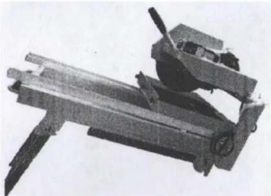
natural_image
Mechanical device with articulated arms and a cylindrical component (no visible text or symbols)This User Manual has been translated for your convenience using machine translation. Reasonable efforts have been made to provide an accurate translation; however, no automated translation is perfect nor is it intended to replace human translators. The official User Manual is the English version. Any discrepancies or differences created in the translation are not binding and have no legal effect for compliance or enforcement purposes. If any questions arise related to the accuracy of the information contained in the User Manual, please refer to the English version of those contents which is the official version.
1. Technical data
| Parameter description | Parameter value |
| Product name | Stone saw |
| Model | MSW-SSAW-2500PRO |
| Rated voltage [V~] / frequency [Hz] | 230 / 50 |
| Rated power [W] | 2500 |
| No load speed [rpm] | 2800 |
| Blade tilt range [°] | 0 - 45 |
| Cutting depth [mm] | 90 (at 90°) / 65 (at 45°) |
| Protection class | 1 |
| IP grade | IP 54 |
| Water Pump | 50 W, max. 800 l/h, IP28 |
| Blade diameter [mm] | ∅350 |
| Blade bore diameter [mm] | 25.4 |
| Duty Cycle | S6 40% |
| Water tank capacity [l] | 37.8 |
| Vibration emission value [m/s2] | 3.4 |
| Sound pressure level [dB] | 72 |
| Sound power [dB] | 85 |
| Table dimensions [cm] | 53 x 43 |
| Dimensions (width x depth x height) [cm] | 120 x 53 x 120 |
| Weight [kg] | 73 |
2. Safety information
Know your power tools. For your safety, read the following instruction manual before operating the saw.
Before turning on the machine
a)

Read the manual carefully before switching on the machine. Understand the tool's actions and limitations to avoid potential hazards.
b) This is an electrical cutting machine. Ensure that children and visitors are kept at a safe distance before operation.
c) Keep the work area clean. Cluttered areas and benches can cause injuries.
d) Consider the work environment.
- Do not expose power tools to rain.
-
Avoid using them in damp or wet locations.
-
Keep the area well lit.
- Do not use tools near flammable liquids or gases.
e) Prevent electric shock by avoiding contact with grounded surfaces such as pipes or radiators.
f) Use the right tool. Do not force small tools to do the job of a heavy-duty tool. Only use the tool for its intended purpose.
g) Use only a diamond wheel for cutting. Do not use any other cutting tool.
h) Ensure the switch is in the "OFF" position before plugging in the power cord.
i) Inspect the diamond wheel before use. Check for cracks, broken parts, or bends. Do not use the wheel if any defects are found. Run a test to confirm it works properly.
j) Maintain tools carefully. Keep them sharp and clean for optimal safety and performance. Follow instructions for lubricating and changing accessories.
k) Use an earth leakage circuit breaker or an isolating transformer to prevent electric shock.
I) Do not use the tool for cutting materials it is not designed for, or for curved cutting. This can damage the diamond wheel or significantly shorten its lifespan.
m) Do not clean plastic parts with solvents. Solvents like gasoline, thinner, or oils containing chlorine can damage and crack plastic parts. Clean with a soft cloth lightly dampened with soapy water.
n) Personal protective equipment must be worn:

- Wear eye protection. Cutting can produce chippings that may injure your eyes, so always wear eye protection.

- Wear a respirator. Cutting generates dust, so wear a respirator to protect your nose and mouth.

- Wear ear protection. The machine is powerful and cutting may generate noise. To protect your ears and concentration, wear ear protection.

- Wear gloves. Always wear gloves during operation. Do not perform any operation freehand.

- Keep hands away from the blade. While cutting, keep your hands clear of the cutting line. The blade is sharp and can cause serious injury.

- Use water cooling. Water cooling improves cutting performance and greatly reduces dust and chipping. Always remember to use water while cutting.
o) Place the workpiece on a portable table and rest it securely against the slide rack before cutting.
p) Use clamps or a vise to hold the workpiece. This is safer than using your hands and frees both hands to operate the tools.
During operation
a) Switch on the machine and wait for it to reach full speed before starting the cutting operation.
b) While cutting, do not disassemble the guards to ensure safety and stability.
c) Never touch the diamond wheel during operation.
d) Do not force the tool. It will work efficiently and safely within its designed limits.
e) If the diamond wheel stops or makes abnormal noises during operation, immediately turn off the switch.
f) Disconnect the tool before servicing or changing accessories like blades, bits, or cutters.
During reuse
a) Inspect for damage before reuse. Check guards and other parts to ensure they function properly. Look for misalignment, binding, breakage, and any conditions that could affect performance. Damaged parts should be repaired or replaced.
b) Use the tool at the correct input level as specified on the nameplate. Operating above the specified input may reduce accuracy and cause motor overload, leading to reduced efficiency.
c) Consult an authorized service agent if the tool malfunctions.
3. Maintenance
1) Inspecting the diamond wheel: A dull diamond wheel can cause motor damage and reduce efficiency. Replace the wheel immediately if you notice signs of wear or abrasion.
2) Inspecting the mounting screws: Regularly check all mounting screws to ensure they are properly tightened. If any screws are loose, retighten them immediately. Failure to do so could result in a serious hazard.
3) Maintaining the motor: The motor winding is a crucial part of the tool. Inspect it carefully to ensure it is not damaged or exposed to oil or water. Clean the entire tool regularly to maintain optimal performance.
4. Application
- Suitable for cutting various types of stones and tiles used in decoration.
• The blade can tilt to any angle between 0^ and 45^ . - The angle ruler on the table can be adjusted to any angle between 0^ and 90^ .
- During cutting, the pump supplies water to the blade, which extends the blade's life and reduces dust.
- To cut, place the material on the table. Adjust the parallel guide so it is perpendicular to the cutting track of the saw blade, then tighten the screw at the end. Secure the ruler in the appropriate position.
- The user can replace components, such as the blade or rubber tube, by themselves.
5. Assembly drawing
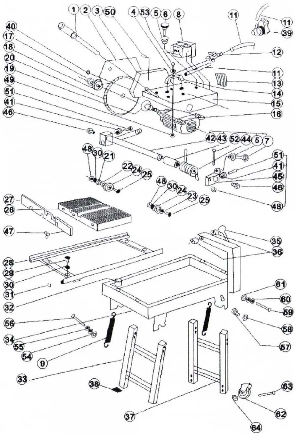
| Part number | Description Quantity | Part number | Description Quantity | ||
| 1 | Hand lever | 1 | 33 | Front leg | 1 |
| 2 | Upper fender | 1 | 34 | Gutter | 4 |
| 3 | Lower fender | 1 | 35 | Locking hand lever | 1 |
| 4 | 28 mm washer | 4 | 36 | Bushing | 1 |
| 5 | Nut M8 | 2 | 37 | Rear leg | 1 |
| 6 | Bolt M8x100 | 1 | 38 | Rubber cushion B | 4 |
| 7 | Bolt M8x60 | 1 | 39 | Water pump | 4 |
| 8 | Switch | 1 | 40 | Nut M6 | 1 |
| 9 | Spring | 2 | 41 | Deflective nut | 4 |
| 10 | Electric wire | 1 | 42 | Revolving shaft | 2 |
| 11 | Tube | 1 | 43 | Spring bushing | 1 |
| 12 | Penstock | 1 | 44 | Spring | 1 |
| 13 | Water fender | 1 | 45 | Revolving block | 1 |
| 14 | Handgrip | 1 | 46 | Bolt M12x25 | 1 |
| 15 | Motor bracket | 1 | 47 | Butterfly bolt | 2 |
| 16 | 2 kW motor | 1 | 48 | Nut M8 | 3 |
| 17 | Left-hand nut M20 | 1 | 49 | Locknut | 4 |
| 18 | Outer flange | 1 | 50 | Brazed joint | 4 |
| 19 | Inner flange | 1 | 51 | Inner hex bolt M8x25 | 2 |
| 20 | Blade 04001 | 1 | 52 | Inner hex bolt M8x50 | 1 |
| 21 | Bearing | 4 | 53 | Bolt M8x45 | 1 |
| 22 | Thick washer | 4 | 54 | Locknut M8 | 4 |
| 23 | Thin washer | 4 | 55 | 8 mm washer | 4 |
| 24 | Idler wheel | 4 | 56 | Bolt M8x50 | 4 |
| 25 | Deflective bolt | 4 | 57 | Bolt M8x12 | 4 |
| 26 | Table | 1 | 58 | Nut M8 | 4 |
| 27 | Table side | 1 | 59 | Bolt M10x60 | 4 |
| 28 | Table guider | 1 | 60 | 10 mm washer | 8 |
| 29 | Bolt M8x25 | 4 | 61 | Locknut M10 | 4 |
| 30 | Flat washer 8 mm | 4 | 62 | Wheel | 2 |
| 31 | Rubber cushion A | 4 | 63 | Bolt M6x50 | 4 |
| 32 | Stopper | 1 | 64 | Nut M6 | 4 |
6. Example of working with the device
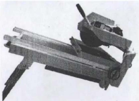
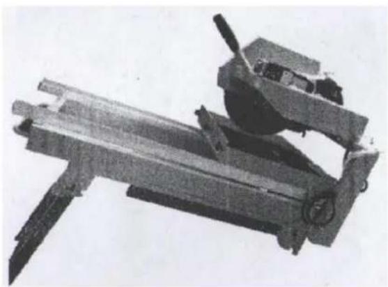
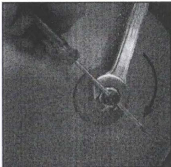
Instruction for 45-Degree Cutting:
1) Loosen the screw (as shown in Picture 2).
2) Adjust the motor to a maximum angle of 45 degrees (refer to Picture 3).
3) Tighten the screw securely before switching the machine on to ensure safe operation.
natural_image
Close-up of a hand using a tool to adjust or install a mechanical component (no visible text or symbols)
natural_image
Close-up of a soldier operating a mounted weapon system (no visible text or symbols)Picture 2 Picture 3
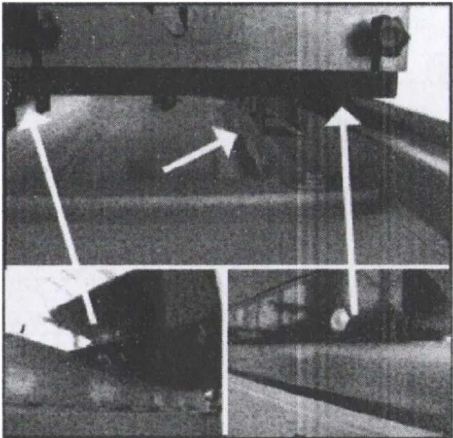
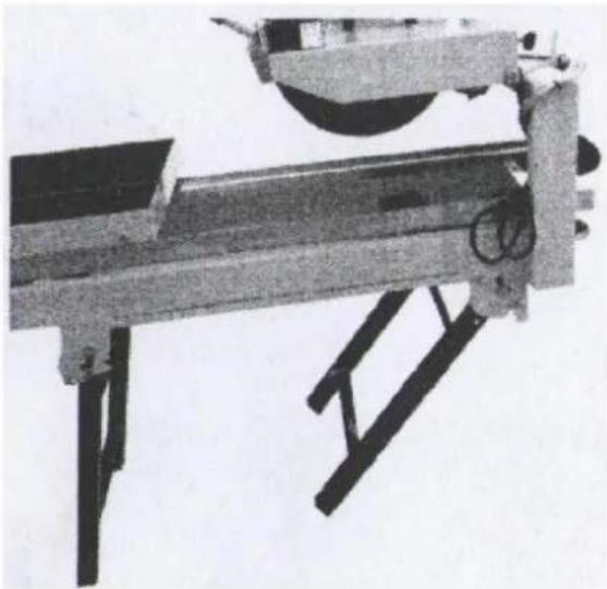
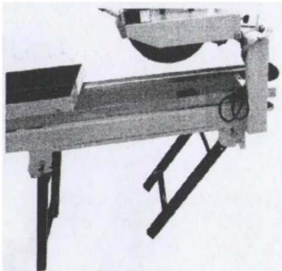
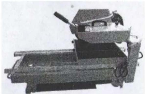
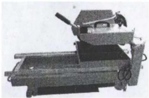
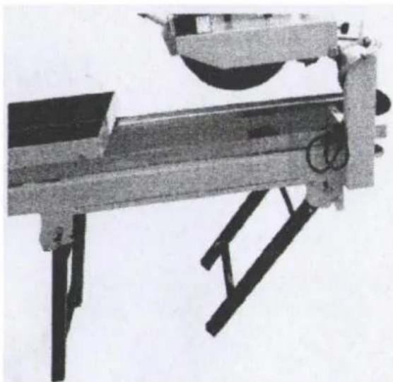
Adjusting the Work Table:
• The work table has 4 location blocks that limit its movement area.
- Ensure the work table is properly installed on the machine to avoid issues like tough movement or even the table falling off while in use (Picture 4).
natural_image
Black-and-white photo of a vehicle undercarriage with white arrows indicating motion direction (no text or symbols)Picture 4
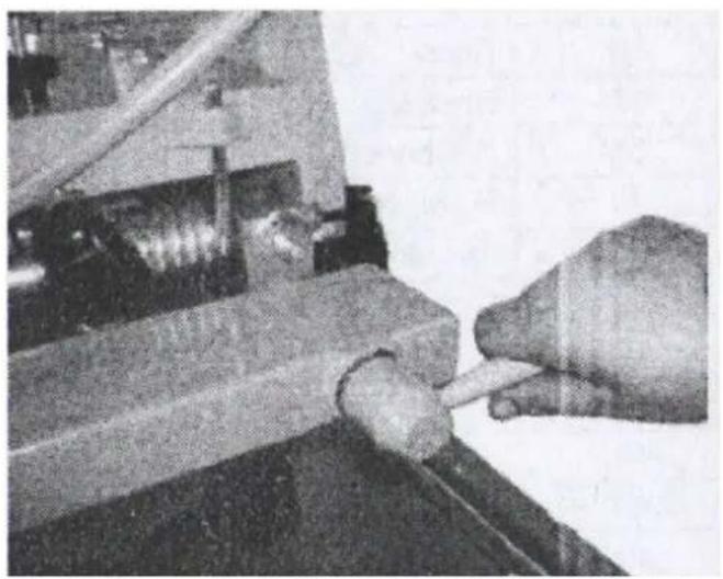
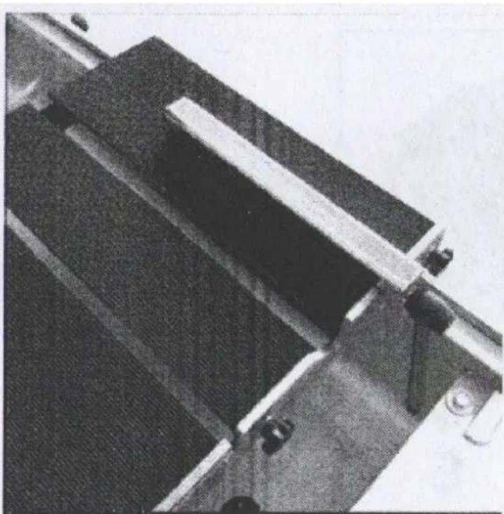
Block Cutting:
1) Loosen the end screw.
2) Adjust the location bar to your desired position.
3) Tighten the end screw and move the work table to begin cutting (Picture 5).
natural_image
Close-up of a mechanical component with dark rectangular blocks and a white horizontal bar (no visible text or symbols)Picture 5
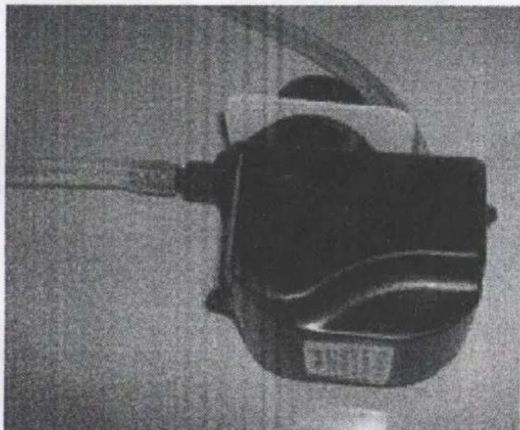
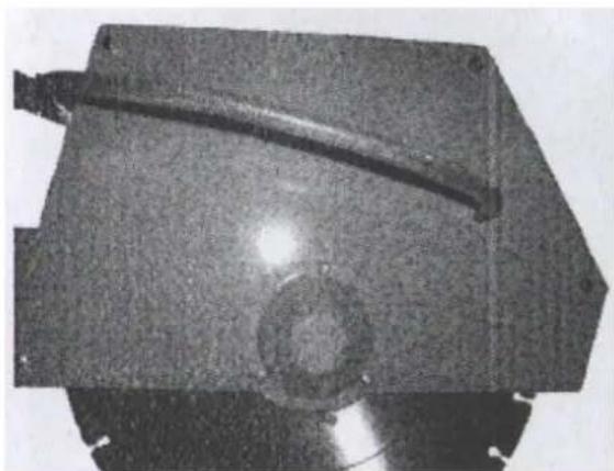
Water Pump Installation:
• Fix the water pump at the specified location (Picture 6).
natural_image
Close-up of a black mechanical device with a cable inserted, possibly a sensor or clamp (no visible text or symbols)Picture 6
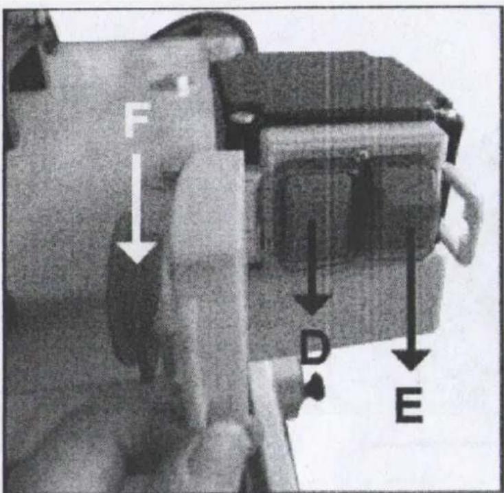
Switch Information (Correction Needed for Picture 7):
Picture 6
• D (Green): Switch ON.
• E (Red): Switch OFF.
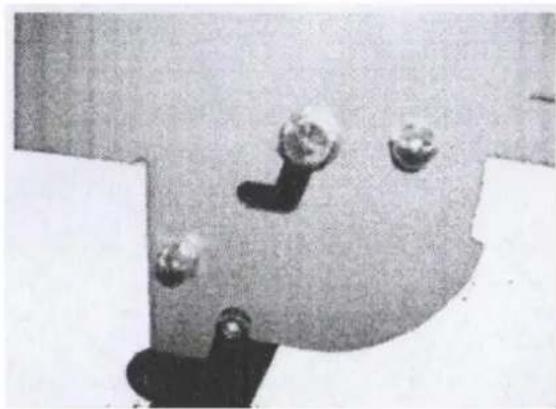
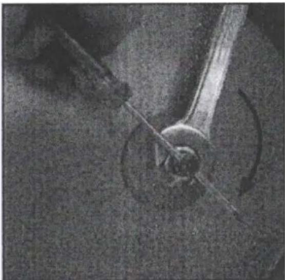
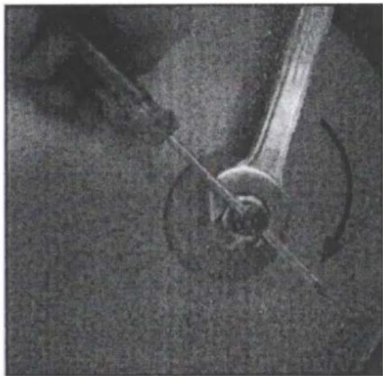
Changing the Cutting Disc:
1) Switch off the machine and wait until the disc stops moving.
2) Unscrew the 4 screws as shown in Picture 8.
3) Use the provided accessories spanner to release the screw by inserting a screwdriver through the middle hole (Picture 9).
natural_image
Close-up of a dark, textured mechanical component with a curved seam and circular hole (no visible text or symbols)Picture 8 Picture 9

natural_image
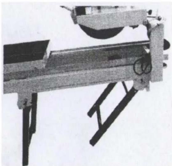
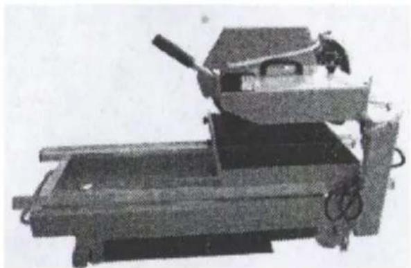
Close-up of a mechanical component with a curved arrow indicating rotation (no visible text or symbols)Folding the Stand:
1) Fold up the stand as shown in Picture 10-2.
2) The final effect should look like Picture 10-3 and 10-4.
natural_image
Close-up of a mechanical component with four spherical components and a curved base (no visible text or symbols)Picture 10-1 Picture 10-2
natural_image
Mechanical device with metal frame and support structure (no visible text or symbols)
natural_image
Mechanical device with lever and base components (no visible text or symbols)Picture 10-3
natural_image
Mechanical device with lever and base plate (no visible text or symbols)Picture 10-4

natural_image
Close-up of a hand using a tool to adjust or install a mechanical component (no visible text or symbols)
natural_image
Black-and-white photo of a military vehicle with mounted weapons and a soldier visible in the background (no text or symbols)Zdjęcie 2 Zdjęcie 3
natural_image
Black-and-white photo showing a vehicle undercarriage with directional arrows indicating movement, no visible text or symbols.Zdjęcie 4
Ciecie bloków:
natural_image
Close-up of a mechanical component with a dark rectangular block and metal bracket (no visible text or symbols)Zdjęcie 5
natural_image
Close-up of a black industrial device with a cable, possibly a welding helmet or safety device (no visible text or symbols)Zdjęcie 6
natural_image
Metallic mechanical component with a curved blade and central hole (no visible text or symbols)
natural_image
Close-up of a mechanical component with a curved shaft and circular base (no visible text or symbols)Zdjęcie 8 Zdjęcie 9
Składanie stojaka:
natural_image
Close-up of a mechanical component with three spherical holes and a curved base (no visible text or symbols)Zdjęcie 10-1
natural_image
Mechanical device with levers and a wheel assembly (no visible text or symbols)Zdjęcie 10-2
natural_image
Mechanical device with articulated arms and a cylindrical component (no visible text or symbols)Zdjęcie 10-3

natural_image
Mechanical device with lever and frame (no visible text or symbols)Zdjęcie 10-4

natural_image
Close-up of a hand using a tool to adjust or install a mechanical component (no visible text or symbols)
natural_image
Close-up of a soldier operating a mounted weapon system (no visible text or symbols)Obrázek 2 Obrázek 3
natural_image
Black-and-white photo of a vehicle undercarriage with white arrows indicating motion direction (no text or symbols)Obrázek 4
Řezání bloků:
natural_image
Close-up of a mechanical component with dark rectangular and metallic surfaces, no visible text or symbolsObrázek 5
natural_image
Close-up of a black mechanical device with a pointed tip and internal components (no visible text or symbols)Obrázek 6
natural_image
Close-up of a dark, textured mechanical component with a curved seam and circular hole (no visible text or symbols)Obrázek 8 Obrázek 9

natural_image
Close-up of a mechanical component with a curved arrow indicating rotation (no visible text or symbols)Skládání stojanu:
natural_image
Close-up of a mechanical component with four spherical components and a curved base (no visible text or symbols)natural_image
Mechanical device with metal frame and support structure (no visible text or symbols)
natural_image
Mechanical device with articulated arms and a central knob (no visible text or symbols)natural_image
Mechanical device with lever and base frame (no visible text or symbols)
natural_image
Close-up of a hand using a tool to adjust or install a mechanical component (no visible text or symbols)
natural_image
Close-up of a mechanical device with visible components and wires (no readable text or symbols)Image 2 Image 3
natural_image
Black-and-white photo of a vehicle undercarriage with directional arrows indicating movement (no text or symbols)Image 4
Découpe de blocs :
natural_image
Close-up of a mechanical component with no visible text or symbolsImage 5
natural_image
Close-up of a black industrial device with a cable, possibly a motor or conveyor device (no visible text or symbols)Image 6
natural_image
Metallic mechanical component with a curved blade and central hole (no visible text or symbols)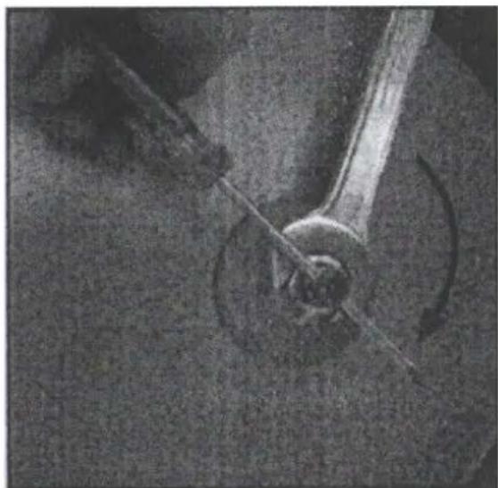
natural_image
Close-up of a mechanical component with a curved shaft and circular base, no visible text or symbolsImage 8 Image 9
Pliage du support :
natural_image
Close-up of a mechanical component with three spherical holes and a curved base (no visible text or symbols)Image 10-1 Image 10-2
natural_image
Mechanical device with levers and a wheel assembly (no visible text or symbols)
natural_image
Mechanical device with lever and base frame (no visible text or symbols)
natural_image
Mechanical device with articulated arms and a cylindrical component (no visible text or symbols)Image 10-3 Image 10-4

natural_image
Close-up of a hand using a tool to adjust or install a mechanical component (no visible text or symbols)
natural_image
Black-and-white photo of a military vehicle with mounted weapons and a soldier visible in the background (no text or symbols)natural_image
Black-and-white photo showing a vehicle undercarriage with directional arrows indicating movement, no visible text or symbols.Immagine 4
Taglio a blocchi:
natural_image
Close-up of a mechanical component with a dark rectangular block and metal bracket (no visible text or symbols)Immagine 5
natural_image
Close-up of a black industrial machine head with a cable, no visible text or symbolsImmagine 6
natural_image
Metallic mechanical component with a curved blade and central hole (no visible text or symbols)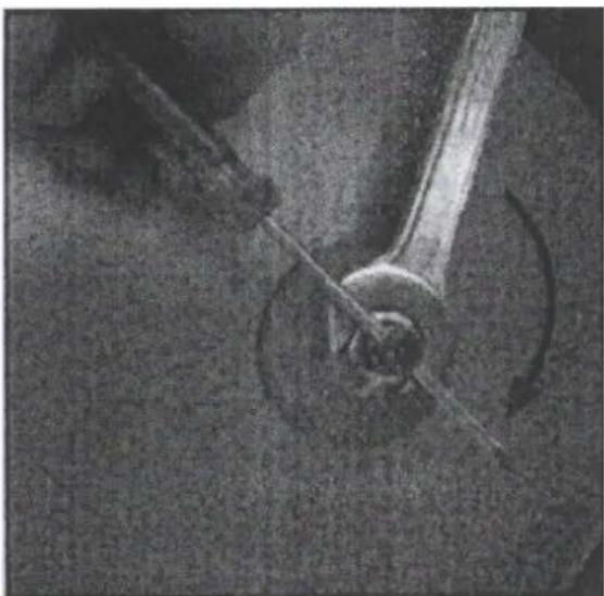
natural_image
Close-up of a mechanical component with a curved arrow indicating rotation (no visible text or symbols)natural_image
Close-up of a mechanical component with three spherical holes and a curved base (no visible text or symbols)natural_image
Mechanical device with levers and a wheel assembly (no visible text or symbols)
natural_image
Mechanical device with lever and base frame (no visible text or symbols)
natural_image
Mechanical device with articulated arms and a cylindrical component (no visible text or symbols)| Número del elemento | Descripción del dispositivo | Cantidad | Número del elemento | Descripción del dispositivo | Cantidad |
| 1 | Palanca de mano | 1 | 33 | Pierna delantera | 1 |
| 2 | Guardabarros superior | 1 | 34 | Canal | 4 |
| 3 Guardarros hacia abajo 1 35 | Palanca de bloqueo manual | 1 | |||
| 4 | Arandela de 28 mm | 4 | 36 | Arbusto | 1 |
| 5 | Tuerca M8 | 2 | 37 | Pierna trasera | 1 |
| 6 | Perno M8x100 | 1 | 38 | Cojín de goma B | 4 |
| 7 | Perno M8x60 | 1 | 39 | Bomba de agua | 4 |
| 8 | Interruptor | 1 | 40 | Tuerca M6 | 1 |
| 9 | Muelle | 2 | 41 | Tuerca deflectora | 4 |
| 10 | Cable eléctrico | 1 | 42 | Eje giratorio | 2 |
| 11 | Tubo | 1 | 43 | Arbusto de primavera | 1 |
| 12 | Compuerta | 1 | 44 | Muelle | 1 |
| 13 | Defensa de agua | 1 | 45 | Bloque giratorio | 1 |
| 14 | Empuñadura | 1 | 46 | Perno M12x25 | 1 |
| 15 | Soporte del motor | 1 | 47 | Perno papilionáceo | 2 |
| 16 | Motor de 2 kW | 1 | 48 | Tuerca M8 | 3 |
| 17 | Tuerca (izquierda) M20 | 1 | 49 | Contratuerca | 4 |
| 18 | Brida exterior | 1 | 50 | Unión soldada | 4 |
| 19 Brida interior 1 51 | Perno hexagonal interior M8x25 | 2 | |||
| 20 Hoja 0 4001 1 52 | Perno hexagonal interior M8x50 | 1 | |||
| 21 | Cojinete | 4 | 53 | Perno M8x45 | 1 |
| 22 | Arandela gruesa | 4 | 54 | Contratuerca M8 | 4 |
| 23 | Arandela fina | 4 | 55 | Arandela de 8 mm | 4 |
| 24 | Rueda loca | 4 | 56 | Perno M8x50 | 4 |
| 25 | Perno deflector | 4 | 57 | Perno M8x12 | 4 |
| 26 | Mesa | 1 | 58 | Tuerca M8 | 4 |
| 27 | Lado de la mesa | 1 | 59 | Perno M10x60 | 4 |
| 28 | Guía de mesa | 1 | 60 | Arandela de 10 mm | 8 |
| 29 | Perno M8x25 | 4 | 61 | Contratuerca M10 | 4 |
| 30 | Arandela plana 8 mm | 4 | 62 | Rueda | 2 |
| 31 | Cojín de goma A | 4 | 63 | Perno M6x50 | 4 |
| 32 | Tope | 1 | 64 | Tuerca M6 | 4 |
natural_image
Close-up of a hand using a tool to adjust or install a mechanical component (no visible text or symbols)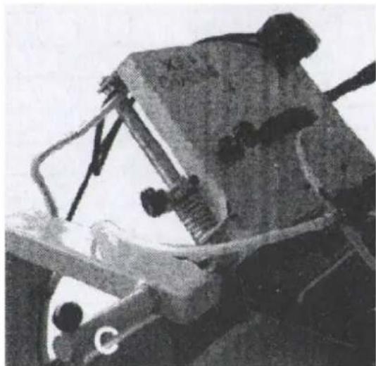
natural_image
Close-up of a mechanical device with visible components and no readable text or symbolsImagen 2 Imagen 3
natural_image
Black-and-white photo of a vehicle undercarriage with directional arrows indicating movement (no text or symbols)Imagen 4
Corte en bloque:
natural_image
Close-up of a mechanical component with a dark rectangular block and metal bracket (no visible text or symbols)Imagen 5
natural_image
Close-up of a black industrial device with a cable, possibly a welding helmet or safety device (no visible text or symbols)Imagen 6
natural_image
Close-up of a dark, textured metal component with a circular hole and mounting holes (no visible text or symbols)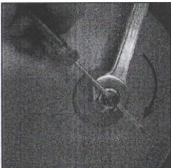
natural_image
Close-up of a mechanical component with a curved wheel and lever, no visible text or symbolsImagen 8 Imagen 9
natural_image
Close-up of a mechanical component with three spherical holes and a curved base (no visible text or symbols)natural_image
Mechanical device with levers and a wheel assembly (no visible text or symbols)
natural_image
Mechanical device with lever and base frame (no visible text or symbols)natural_image
Mechanical device with lever and base frame (no visible text or symbols)
natural_image
Close-up of a hand using a tool to adjust or install a mechanical component (no visible text or symbols)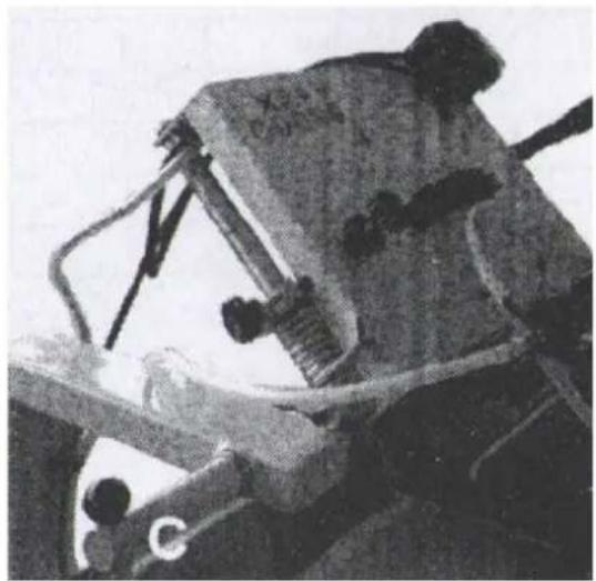
natural_image
Close-up of a military vehicle with mounted weapon system (no visible text or symbols)- kép 3. kép
natural_image
Black-and-white photo of a train undercarriage with directional arrows indicating movement (no text or symbols)- kép
Blokkvágás:
natural_image
Close-up of a mechanical component with a rectangular slot and mounting holes (no visible text or symbols)- kép
natural_image
Close-up of a black mechanical device with a pointed tip and internal components (no visible text or symbols)- kép
natural_image
Close-up of a dark, textured mechanical component with a curved seam and circular hole (no visible text or symbols)- kép 9. kép

natural_image
Close-up of a mechanical component with a curved arrow indicating rotation (no visible text or symbols)natural_image
Close-up of a mechanical component with four spherical components and a curved base (no visible text or symbols)10-1. kép

natural_image
Mechanical device with metal frame and support structure (no visible text or symbols)10-2. kép
natural_image
Mechanical device with lever and base components (no visible text or symbols)10-3. kép
natural_image
Mechanical device with lever and base frame (no visible text or symbols)10-4. kép

| Delnummer | Beskrivelse af apparatet | Antal | Delnummer | Beskrivelse af apparatet | Antal |
| 1 | Håndtag | 1 | 33 | Forreste ben | 1 |
| 2 | ∅vre skærm | 1 | 34 | Tagrende | 4 |
| 3 | Nedadgående skærm | 1 | 35 | Lås håndtaget | 1 |
| 4 | 28 mm skive | 4 | 36 | Bush | 1 |
| 5 | Møtrik M8 | 2 | 37 | Bageste ben | 1 |
| 6 | Bolt M8x100 | 1 | 38 | Gummipude B | 4 |
| 7 | Bolt M8x60 | 1 | 39 | Vandpumpe | 4 |
| 8 | Kontakt | 1 | 40 | Møtrik M6 | 1 |
| 9 | Fjeder | 2 | 41 | Afbøjningsmøtrik | 4 |
| 10 | Elektrisk ledning | 1 | 42 | Drejelig aksel | 2 |
| 11 | Rør | 1 | 43 | Forårsbusk | 1 |
| 12 | Penstock | 1 | 44 | Fjeder | 1 |
| 13 | Vandskærm | 1 | 45 | Drejelig blok | 1 |
| 14 | Håndgreb | 1 | 46 | Bolt M12x25 | 1 |
| 15 | Motorkonsol | 1 | 47 | Papilionaceous bolt | 2 |
| 16 | Motor 2 kW | 1 | 48 | Møtrik M8 | 3 |
| 17 | Møtrik (venstre) M20 | 1 | 49 | Låsemøtrik | 4 |
| 18 Udvendig flange 1 50 | Loddet sammenføjning | 4 | |||
| 19 Indvendig flange 1 51 | Indvendig sekskantbolt M8x25 | 2 | |||
| 20 | Blad 0 4001 | 1 | 52 | Indvendig sekskantbolt M8x50 | 1 |
| 21 | Leje | 4 | 53 | Bolt M8x45 | 1 |
| 22 | Tyk skive | 4 | 54 | Låsemøtrik M8 | 4 |
| 23 | Tynd skive | 4 | 55 | 8 mm skive | 4 |
| 24 | Tomgangshjul | 4 | 56 | Bolt M8x50 | 4 |
| 25 | Afbøjningsbolt | 4 | 57 | Bolt M8x12 | 4 |
| 26 | Bord | 1 | 58 | Møtrik M8 | 4 |
| 27 | Bordets side | 1 | 59 | Bolt M10x60 | 4 |
| 28 | Guide til bordet | 1 | 60 | 10 mm skive | 8 |
| 29 | Bolt M8x25 | 4 | 61 | Låsemøtrik M10 | 4 |
| 30 | Flad skive 8 mm | 4 | 62 | Hjul | 2 |
| 31 | Gummipude A | 4 | 63 | Bolt M6x50 | 4 |
| 32 | Stopper | 1 | 64 | Møtrik M6 | 4 |
natural_image
Close-up of a hand using a tool to adjust or install a mechanical component (no visible text or symbols)
natural_image
Black-and-white photo of a soldier operating a mounted weapon system (no visible text or symbols)Billede 2 Billede 3
natural_image
Black-and-white photo of a vehicle undercarriage with white arrows indicating motion direction (no text or symbols)Billede 4
Skæring af blokke:
natural_image
Close-up of a mechanical component with diagonal braces and mounting holes (no visible text or symbols)Billede 5
Installation af vandpumpe:
natural_image
Close-up of a black mechanical device with a cable inserted, no visible text or symbolsBillede 6
natural_image
Close-up of a dark, textured mechanical component with a curved rod and circular hole (no visible text or symbols)Billede 8 Billede 9
natural_image
Close-up of a mechanical component with a curved arrow indicating rotation (no visible text or symbols)natural_image
Close-up of a metallic mechanical component with four spherical components and a curved base (no visible text or symbols)natural_image
Mechanical device with metal frame and support structure (no visible text or symbols)
natural_image
Mechanical device with lever and base components (no visible text or symbols)natural_image
Mechanical device with lever and base frame (no visible text or symbols)
natural_image
Close-up of a hand using a tool to adjust or install a mechanical component (no visible text or symbols)
natural_image
Close-up of a soldier operating a mounted weapon system (no visible text or symbols)Kuva 2 Kuva 3
natural_image
Black-and-white photo of a vehicle undercarriage with white arrows indicating motion direction (no text or symbols)Kuva 4
Lohkon leikkaus:
natural_image
Close-up of a mechanical component with diagonal braces and mounting holes (no visible text or symbols)Kuva 5
Vesipumpun asennus:
natural_image
Close-up of a black mechanical device with a cable inserted, possibly a sensor or clamp (no visible text or symbols)Kuva 6
natural_image
Close-up of a dark, textured mechanical component with a curved seam and circular hole (no visible text or symbols)Kuva 8 Kuva 9
natural_image
Close-up of a mechanical component with a curved arrow indicating rotation (no visible text or symbols)natural_image
Close-up of a metallic mechanical component with four spherical components and a curved base (no visible text or symbols)Kuva 10-1 Kuva 10-2

natural_image
Mechanical device with metal frame and support structure (no visible text or symbols)
natural_image
Mechanical device with lever and base components (no visible text or symbols)Kuva 10-3 Kuva 10-4
natural_image
Mechanical device with lever and base frame (no visible text or symbols)
natural_image
Close-up of a hand using a tool to adjust or install a mechanical component (no visible text or symbols)
natural_image
Close-up of a mechanical device with visible components and no readable text or symbolsnatural_image
Black-and-white photo of a vehicle undercarriage with directional arrows indicating movement (no text or symbols)Afbeelding 4
Bloksnijden:
natural_image
Close-up of a mechanical component with a dark rectangular block and metal bracket (no visible text or symbols)Afbeelding 5
Installatie waterpomp:
natural_image
Close-up of a black industrial device with a cable, possibly a welding helmet or safety device (no visible text or symbols)Afbeelding 6
natural_image
Close-up of a dark, textured metal component with a circular hole and mounting holes (no visible text or symbols)natural_image
Close-up of a mechanical component with a curved arrow indicating rotation (no visible text or symbols)natural_image
Close-up of a mechanical component with three spherical holes and a curved base (no visible text or symbols)natural_image
Mechanical device with levers and gears, no visible text or symbols
natural_image
Mechanical device with lever and base frame (no visible text or symbols)
natural_image
Mechanical device with articulated arms and a cylindrical component (no visible text or symbols)| Artikkelnummer | Beskrivelse | Antall | Artikkelnummer | Beskrivelse | Antall |
| 1 | Håndspak | 1 | 33 | Fremre ben | 1 |
| 2 | ∅vre skjerm | 1 | 34 | Renne | 4 |
| 3 | Nedskjerm | 1 | 35 | Lås håndspaken | 1 |
| 4 | 28 mm skive | 4 | 36 | Busk | 1 |
| 5 | Mutter M8 | 2 | 37 | Bakre ben | 1 |
| 6 | Bolt M8x100 | 1 | 38 | Gummipute B | 4 |
| 7 | Bolt M8x60 | 1 | 39 | Vannpumpe | 4 |
| 8 | Bryter | 1 | 40 | Mutter M6 | 1 |
| 9 | Fjær | 2 | 41 | Avbøyende mutter | 4 |
| 10 | Elektrisk ledning | 1 | 42 | Roterende aksel | 2 |
| 11 | Rør | 1 | 43 | Vårbusk | 1 |
| 12 | Pennestokk | 1 | 44 | Fjær | 1 |
| 13 | Vannskjerm | 1 | 45 | Roterende blokk | 1 |
| 14 | Håndtak | 1 | 46 | Bolt M12x25 | 1 |
| 15 | Motorbrakett | 1 | 47 | Papilionaktig bolt | 2 |
| 16 | Motor 2 kW | 1 | 48 | Mutter M8 | 3 |
| 17 | Mutter (venstre) M20 | 1 | 49 | Låsemutter | 4 |
| 18 | Ytre flens | 1 | 50 | Loddet sammenføyning | 4 |
| 19 Innvendig flens 1 51 | Innvendig sekskantbolt M8x25 | 2 | |||
| 20 | Blad 0 4001 | 1 | 52 | Innvendig sekskantbolt M8x50 | 1 |
| 21 | Peiling | 4 | 53 | Bolt M8x45 | 1 |
| 22 | Tykk skive | 4 | 54 | Låsemutter M8 | 4 |
| 23 | Tynn skive | 4 | 55 | 8 mm skive | 4 |
| 24 | Tomgangshjul | 4 | 56 | Bolt M8x50 | 4 |
| 25 | Avbøyende bolt | 4 | 57 | Bolt M8x12 | 4 |
| 26 | Bord | 1 | 58 | Mutter M8 | 4 |
| 27 | Bordsiden | 1 | 59 | Bolt M10x60 | 4 |
| 28 | Fører av bord | 1 | 60 | 10 mm skive | 8 |
| 29 | Bolt M8x25 | 4 | 61 | Låsemutter M10 | 4 |
| 30 | Flat skive 8 mm | 4 | 62 | Hjul | 2 |
| 31 | Gummipute A | 4 | 63 | Bolt M6x50 | 4 |
| 32 | Kork | 1 | 64 | Mutter M6 | 4 |
natural_image
Close-up of a hand using a tool to adjust or install a mechanical component (no visible text or symbols)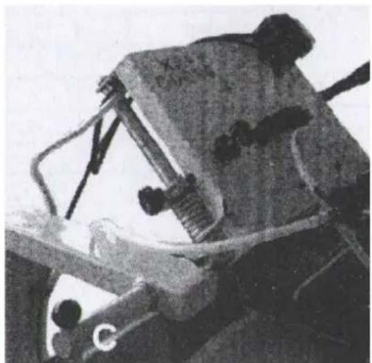
natural_image
Black-and-white photo of a person operating a mechanical device with visible wiring and components (no text or symbols)Bilde 2 Bilde 3
natural_image
Black-and-white photo showing a vehicle undercarriage with directional arrows indicating movement, no visible text or symbols.Bilde 4
Blokkskjæring:
natural_image
Close-up of a mechanical component with a dark rectangular block and metal bracket (no visible text or symbols)Bilde 5
natural_image
Close-up of a black industrial device with a cable, possibly a welding helmet or safety device (no visible text or symbols)Bilde 6
natural_image
Close-up of a dark, textured metal component with a circular hole and mounting holes (no visible text or symbols)
natural_image
Close-up of a mechanical component with a curved arrow indicating rotation (no visible text or symbols)Bilde 8 Bilde 9
natural_image
Close-up of a mechanical component with three spherical holes and a curved base (no visible text or symbols)natural_image
Mechanical device with levers and a wheel assembly (no visible text or symbols)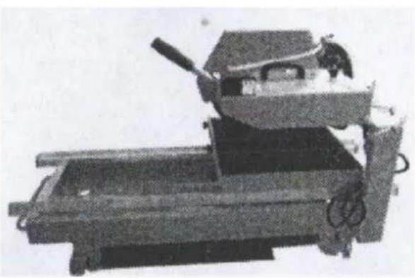
natural_image
Mechanical device with lever and base frame (no visible text or symbols)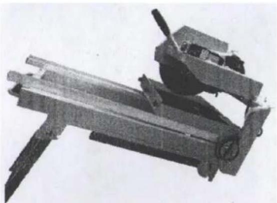
natural_image
Mechanical device with articulated arms and a cylindrical component (no visible text or symbols)| Nummer på del | Beskrivning Antal | Nummer på del | Beskrivning Antal | ||
| 1 | Handspak | 1 | 33 | Framben | 1 |
| 2 | Övre stänkskärm | 1 | 34 | Ränna | 4 |
| 3 | Dunskärm | 1 | 35 | Lås handtaget | 1 |
| 4 | 28 mm bricka | 4 | 36 | Buske | 1 |
| 5 | Mutter M8 | 2 | 37 | Bakre ben | 1 |
| 6 | Bult M8x100 | 1 | 38 | Gummikudde B | 4 |
| 7 | Bult M8x60 | 1 | 39 | Vattenpump | 4 |
| 8 | Växla | 1 | 40 | Mutter M6 | 1 |
| 9 | Fjäder | 2 | 41 | Deflektiv mutter | 4 |
| 10 | Elektrisk tråd | 1 | 42 | Roterande axel | 2 |
| 11 | Rör | 1 | 43 | Vårbuske | 1 |
| 12 | Penstock | 1 | 44 | Fjäder | 1 |
| 13 | Vattenskärm | 1 | 45 | Roterande block | 1 |
| 14 | Handtag | 1 | 46 | Bult M12x25 | 1 |
| 15 | Motorfäste | 1 | 47 | Papilionaktig bult | 2 |
| 16 | Motor 2 kW | 1 | 48 | Mutter M8 | 3 |
| 17 | Mutter (vänster) M20 | 1 | 49 | Låsmutter | 4 |
| 18 | Ytterfläns | 1 | 50 | Löd fogning | 4 |
| 19 Inre fläns 1 51 | Inre sexkantsbult M8x25 | 2 | |||
| 20 | Blad 0 4001 | 1 | 52 | Inre sexkantsbult M8x50 | 1 |
| 21 | Lager | 4 | 53 | Bult M8x45 | 1 |
| 22 | Tjock bricka | 4 | 54 | Låsmutter M8 | 4 |
| 23 | Tunn bricka | 4 | 55 | 8 mm bricka | 4 |
| 24 | Tomgångshjul | 4 | 56 | Bult M8x50 | 4 |
| 25 | Avböjande bult | 4 | 57 | Bult M8x12 | 4 |
| 26 | Tabell | 1 | 58 | Mutter M8 | 4 |
| 27 | Bordssidan | 1 | 59 | Bult M10x60 | 4 |
| 28 | Styrare av bordet | 1 | 60 | 10 mm bricka | 8 |
| 29 | Bult M8x25 | 4 | 61 | Låsmutter M10 | 4 |
| 30 | Platt bricka 8 mm | 4 | 62 | Hjul | 2 |
| 31 | Gummikudde A | 4 | 63 | Bult M6x50 | 4 |
| 32 | Propp | 1 | 64 | Mutter M6 | 4 |
natural_image
Close-up of a hand using a tool to adjust or install a mechanical component (no visible text or symbols)
natural_image
Close-up of a soldier operating a mounted weapon system (no visible text or symbols)Bild 2 Bild 3
natural_image
Black-and-white photo of a vehicle undercarriage with white arrows indicating motion direction (no text or symbols)Bild 4
Blockskärning:
natural_image
Close-up of a mechanical component with diagonal braces and mounting holes (no visible text or symbols)Bild 5
natural_image
Close-up of a black mechanical device with a cable inserted, no visible text or symbolsBild 6
natural_image
Close-up of a dark, textured mechanical component with a curved seam and circular hole (no visible text or symbols)Bild 8 Bild 9

natural_image
Close-up of a mechanical component with a curved arrow indicating rotation (no visible text or symbols)natural_image
Close-up of a mechanical component with four spherical components and a curved base (no visible text or symbols)Bild 10-1
natural_image
Mechanical device with metal frame and support structure (no visible text or symbols)Bild 10-2

natural_image
Mechanical device with articulated arms and a central knob (no visible text or symbols)Bild 10-3 Bild 10-4

natural_image
Mechanical device with lever and base frame (no visible text or symbols)
natural_image
Close-up of a hand using a tool to adjust or install a mechanical component (no visible text or symbols)
natural_image
Black-and-white photo of a soldier operating a mounted weapon system (no visible text or symbols)Imagem 2 Imagem 3
natural_image
Black-and-white photo of a train undercarriage with directional arrows indicating movement (no text or symbols)Imagem 4
Corte em bloco:
natural_image
Close-up of a mechanical component with a rectangular slot and mounting holes (no visible text or symbols)Imagem 5
natural_image
Close-up of a black mechanical device with a cable inserted, no visible text or symbolsFoto 6
natural_image
Close-up of a dark, textured mechanical component with a curved seam and circular hole (no visible text or symbols)Imagem 8 Imagem 9
natural_image
Close-up of a mechanical component with a curved arrow indicating rotation (no visible text or symbols)Dobrando o suporte:
1) Dobre o suporte conforme mostrado na Figura 10-2.
natural_image
Close-up of a mechanical component with four spherical components and a curved base (no visible text or symbols)natural_image
Mechanical device with metal frame and support structure (no visible text or symbols)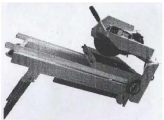
natural_image
Mechanical device with articulated arms and a cylindrical component (no visible text or symbols)natural_image
Mechanical device with lever and base frame (no visible text or symbols)
natural_image
Close-up of a hand using a tool to adjust or install a mechanical component (no visible text or symbols)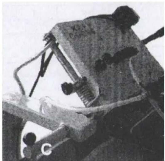
natural_image
Black-and-white photo of a soldier operating a mounted weapon system (no visible text or symbols)Obrázok 2 Obrázok 3
natural_image
Black-and-white photo of a vehicle undercarriage with white arrows indicating motion direction (no text or symbols)Obrázok 4