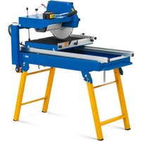
SBBD-4500MAX - Saw MSW - Free user manual and instructions
Find the device manual for free SBBD-4500MAX MSW in PDF.

| Product type | Table circular saw |
| Brand | MSW |
| Model | SBBD-4500MAX |
| Supply voltage | 400 V / 50 Hz (three-phase) |
| Power | 4200 W (S6 40%) |
| No-load speed | 2800 rpm |
| Cutting depth at 90° | 150 mm |
| Compatible blade diameter | 450–500 mm |
| Main functions | Longitudinal, cross and miter cuts (0–90°) |
| Safety devices | Protective cover, riving knife, emergency stop |
| Dust extraction system | Connection possible (min. air speed 20 m/s) |
| Included accessories | Parallel guide, miter guide, push stick, sliding board, transport wheels, keys, hook |
| Table dimensions | With extensions: approx. 1200 x 800 mm (estimated) |
| Approximate weight | Approx. 80 kg |
| Routine maintenance | Cleaning after each use, monthly lubrication of moving parts |
| Blade change | Requires loosening the M20 nut (left-hand thread), wear gloves |
| Riving knife adjustment | Blade-knife distance: 3–8 mm |
| Electrical connection | Via CEE 400 V plug, residual current circuit breaker mandatory |
| Spare parts available | Blade, riving knife, cover, guide, wheels, etc. |
| Repairability | Possible with original parts, intervention by a qualified electrician recommended |
Frequently Asked Questions - SBBD-4500MAX MSW
User questions about SBBD-4500MAX MSW
0 question about this device. Answer the ones you know or ask your own.
Ask a new question about this device
Download the instructions for your Saw in PDF format for free! Find your manual SBBD-4500MAX - MSW and take your electronic device back in hand. On this page are published all the documents necessary for the use of your device. SBBD-4500MAX by MSW.
USER MANUAL SBBD-4500MAX MSW
natural_image
Red and silver metal machine with cutaway view, no visible text or symbolsMONTAGE
natural_image
Two technical diagrams showing a mechanical assembly with labeled 'S' components (no text or symbols present)
natural_image
Technical line drawing of a mechanical assembly with bracket and mounting features, labeled A and B (no text or symbols on the diagram itself)natural_image
Technical line drawing of a mechanical frame with wheels and a labeled component (no text or symbols beyond the label '1')Montage der Transporträder
natural_image
Close-up of a mechanical assembly with black components and a numbered label '1' (no readable text or symbols)natural_image
Technical line drawing of a mechanical component with a screwdriver and housing (no text or symbols)natural_image
Technical line drawing of a mechanical assembly with saw and clamping components (no text or symbols)
natural_image
Technical line drawing of a mechanical assembly with wooden components and mounting brackets (no text or symbols)
HINWEIS
natural_image
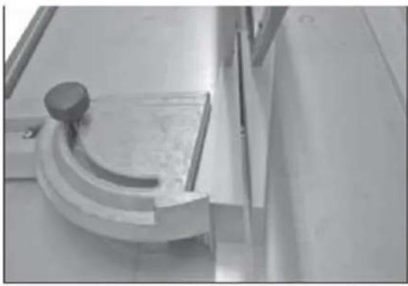
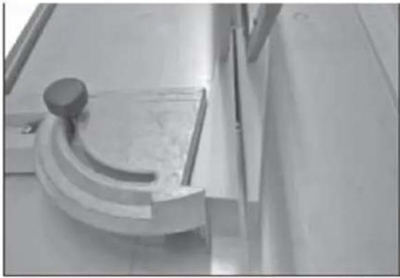
Close-up of a metallic mechanical component with a curved bracket and mounting holes (no visible text or symbols)Keile schneiden
natural_image
Close-up of a mechanical component with a curved bracket and circular knob, mounted on a flat surface (no visible text or symbols)
ACHTUNG!
natural_image
Pure diagram of a rectangular object with labeled 'S' and two blue arrows pointing to its edges (no text or symbols beyond labels)
natural_image
Close-up of a mechanical gear mechanism with visible teeth and central hub (no text or symbols)1- Maschine
natural_image
Mechanical setup with labeled components, no visible text or symbols1- ON-OFF-Schalter
This User Manual has been translated for your convenience using machine translation. Reasonable efforts have been made to provide an accurate translation; however, no automated translation is perfect nor is it intended to replace human translators. The official User Manual is the English version. Any discrepancies or differences created in the translation are not binding and have no legal effect for compliance or enforcement purposes. If any questions arise related to the accuracy of the information contained in the User Manual, please refer to the English version of those contents which is the official version.
Technical data
| Parameter description | Parameter value |
| Product name | Table Saw |
| Model | MSW-SBBD-4500MAX |
| Voltage [V~] / Frequency [Hz] | 400/50 |
| Power [W] | 4200 (S6 40%) |
| No load speed [rpm] | 2800 |
| Cutting depth [mm] | 150 at 90° |
| Saw blade diameter [mm] | 500 |
Purpose
Table saw is to make precise and efficient cuts in various types of wood and other materials. It is primarily used for making straight cuts, both along the length (ripping) and across the width (cross-cutting) of a workpiece.
Product Overview
natural_image
Red and silver metal machine with open lid and workpiece, no visible text or symbolsASSEMBLY
1. Checking Scope of Supply
Check the machine immediately after delivery for transport damage and missing parts.
2. The workplace
Choose a suitable place for the machine. Pay attention to the safety requirements and the dimensions of the machine. The selected location must ensure a suitable connection to the electrical network as well as the possibility of connection to a dust collection system. Make sure that the machine is placed on a solid and level surface and that the ground can support the load of the machine. The machine must be levelled simultaneously at all support points. It is also necessary to secure a distance of at least 0.8 m around the machine. In front of and behind the machine, the necessary distance must be provided for the feeding of long workpieces.
3. Assembling the machine
The machine has been disassembled for transport and must be assembled before use. Follow the instructions below:

WARNING!
Handling the machine assembly while it is connected to the mains supply can result in serious injury or death. Therefore, do not connect the machine to the power supply before completing the assembly.
natural_image
Technical line drawing of a mechanical assembly with vertical supports and a cylindrical component (no text or symbols)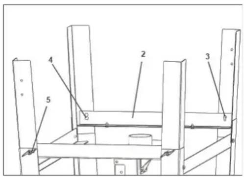
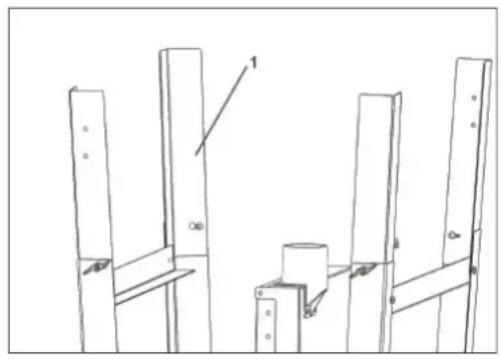
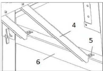
Assembly of base-frame
- Raise the lower support leg (1).
-
Mount the short cross support (2), align the mounting hole (3) and tighten the half-round cap screws (4) with locking knobs (5).
-
Then set the machine up

natural_image
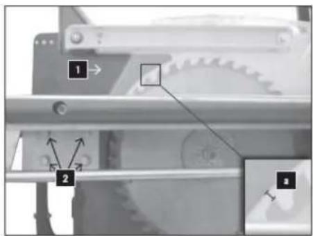
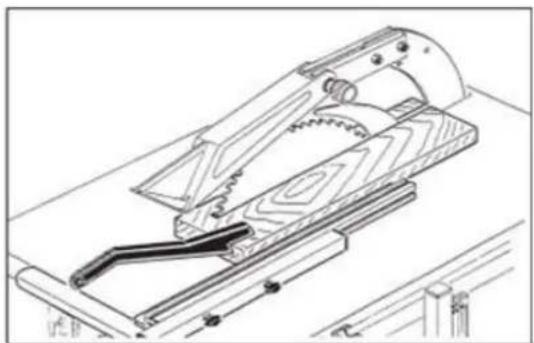
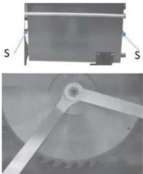
Two-panel image showing a mechanical assembly with labeled 'S' and a close-up of a rotating wheel (no text or symbols present)Assembly of saw blade
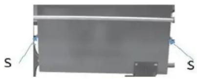
Loose two screws M8 (S) on the saw blade cover (1):
-
Swivel off the saw blade cover.
-
Loosen the clamping nut (M20, left-hand thread).

CAUTION!
When handling circular saw blades when changing tools, please use safety gloves to avoid risk of injury.
Install the saw blade:
NOTE: Use only well sharpened, crack-free and not deformed saw blades.
-
Tighten clamping nut, with holding wrench (LEFT- HAND THREAD!)
-
Fold up the saw blade cover and tighten both screws M8 again.
Assembly of riving knife with saw blade protection cover
-
Place the already mounted saw blade protection cover with riving knife from above between guide plate and clamping plate.
-
Set the distance between riving knife and saw blade to 3 - 8 mm (a) and tighten the clamping plate with four hexagon head screws and washers (2).
NOTE:
• The cover is mounted ready for operation and must not be removed for operation.
• Make sure that the cover always rests on the table top with its own weight, but that the two screws are tightened backlash-free.
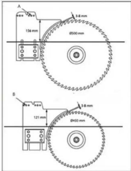
A. Position for saw blade protection cover ( 500mm )
B. Position for saw blade protection cover ( 450mm )
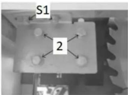
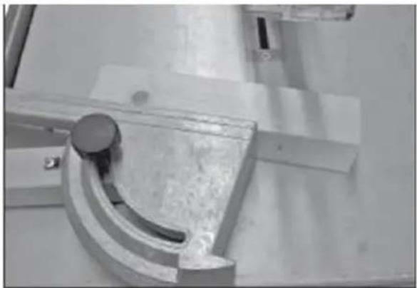
Adjustment of riving knife (alignment)
- The riving knife must be aligned with the saw blade, otherwise it must be corrected. Firstly, Loosen the 2 hexagon head screws (S1) on both sides.
- Align the riving knife.
- Slightly tighten the hexagon head screws (S1).
- Align the riving knife to the saw blade and retighten the four hexagon head screws (S1).
- Check the gap setting for the saw blade.
- The distance between saw blade and riving knife must not exceed 8 mm and must be at least 3 mm. This setting should be checked and readjusted if necessary.
- To do this, loosen the 4 hexagon head screws (2) and adjust the height of the riving knife.
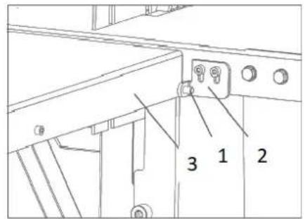

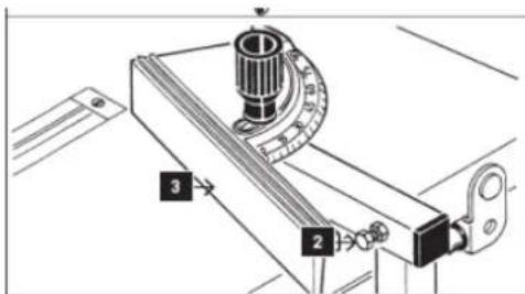
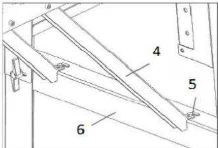
Assembly of table extension
- Assemble the table extension (1) to the right and left of the main table (2) with two screws (3), washers and nuts each. Tighten the nuts lightly by hand.
- Fold out support bracket (4) for table extension and engage table.
Adjust the height of the table extension
- Place the ruler on the saw table and the table extension and align the table extension in height.
- Tighten with the screws on the saw table (3) and on the support (5).

natural_image
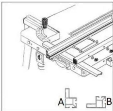
Technical line drawing of a mechanical assembly with bracket and mounting features, labeled A and B (no text or symbols on the diagram itself)Assembly of rip-fence
- Fasten the clamping device (1) for the rip-fence(stop) to the table top with two cheese head screws M6, two washers and two nuts.
- Attach the fixing plate (2) to the stop fixing (3) using two M6 screws, two washers and two nuts.
NOTE Do not tighten yet.
- Insert stop
High contact surface in position (A)
Low contact surface in position (B)
and then clamp it.
• Insert rip-fence in clamping device
Operation instruction:
Locking/clamp = lift flap
release = press down the flap
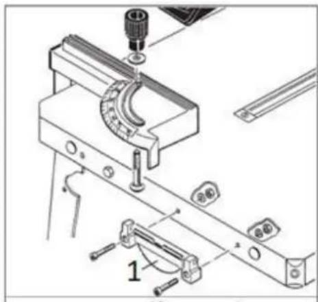
Assembly of mitre gauge
Insert a round-head screw M8 x 70 from below into the mitre gauge, fix with 8 mm washer and handle.
Carry out adjustment:
Adjust the 90° angle between the stop (3) and the saw blade using the hexagon head screw (2).
(Use a right-angle gauge that is not included in the scope of delivery and then make a test cut for verification)
natural_image
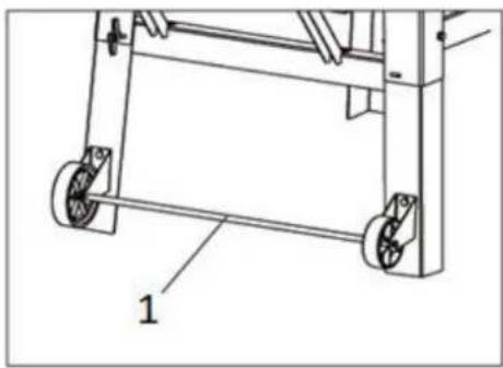
Technical line drawing of a mechanical frame with wheels and a labeled component (no text or symbols beyond the label '1')Assembly of transport wheels
Assemble the wheel group (1) to the lower support leg using bolts and nuts.
natural_image
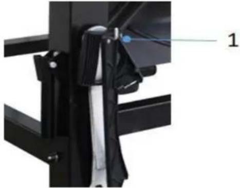
Close-up of a mechanical assembly with black components and a numbered label '1' (no readable text or symbols)Assembly of hook for push-stick tools
Attach the hook to the frame using the nut
Electrical Connection

WARNING
Dangerous electrical voltage! The machine may only be connected to the mains supply and the associated checks carried out by a qualified electrician or under the instruction and supervision of a qualified electrician!

NOTE
Immediately after making the electrical connection, check the running direction of the band saw rollers. Observe the direction arrow on the machine. The running direction is correct if the saw band runs from top to bottom. If this is not the case, swap two phases, e.g.: L1 and L2, on the mains plug or on the phase changing switch.
natural_image
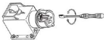
Technical line drawing of a mechanical component with a screwdriver and housing (no text or symbols)The electrical connection is made via a switch-plug combination. This device must be operated via a residual current circuit breaker.
Establishing a 400 V connection
To connect the machine to the electrical mains, proceed as follows:
- Use a suitable device to check the functionality of the zero connection and earthing.
- Check that supply voltage and current frequency correspond to the specifications on the machine nameplate. A deviation of ±5% from the value of the supply voltage is permissible. For example, a machine with a working voltage of 380 V can work in the voltage range from 370 to 400 V. The machine can be operated with a working voltage of 380 V in the voltage range from 370 to 400 V. The machine can also be operated with a working voltage of 380 V in the voltage range from 370 to 400 V. There must be a short-circuit fuse in the power supply of the machine!
- For the required cross-section of the supply cable please refer to the current-carrying capacity table.
- It is recommended to use a cable of type H07RN (WDE0282), which must be protected against mechanical damage.
- Connect the supply cable to the appropriate terminals in the input box (L1, L2, L3, N, PE) - see the figure below. If a CEE plug is present, the connection to the mains is made via an appropriately supplied CEE coupling (L1, L2, L3, N, PE).
Connecting to a dust collection system

NOTICE
The machine must be connected to a dust collection system. The system must start up at the same time as the motor of the band saw starts. For materials with a humidity < 12% , the air velocity at the dust collector port and in the hoses must be at least 20~m / s (for moist chips with a humidity >12% , at least 28~m / s ). The suction hoses used must be flame-retardant (DIN4102 B1), permanently antistatic (or grounded on both sides) and comply with the relevant safety regulations. Requirements for the dust collection system refers to the technical data.
OPERATION
Initial check before start
- Check that the max. speed of the machine is lower than the max. permissible speed of the used saw blade and direction is correct.
- Use only sawblades with a diameter of between 450 and 500mm.
- The riving knife is correctly adjusted.
- Saw blade is not damaged.
- All guards are fitted and in proper condition.
- If necessary, check whether the connection to a dust collection system is available.

WARNING
The guards must not be manipulated; in particular, the self-closing mechanism of saw blade guards must not be blocked (e.g. by using keys).
Operation procedures
Starting the machine
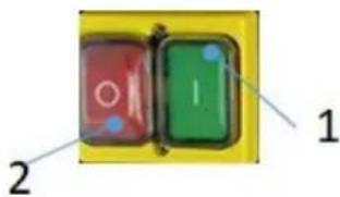
Starting saw blade movement by pressing button (1)
Stopping machine
Normal stop:
Press the OFF-button (2). Both blades stop movement.
Notes on using the table saw
Longitudinal cuts
When performing this operation, the following equipment shall be used for safe working:
- Rip-fence
• the guard of the saw blade
• the riving knife
• the insert in the table - push stick when cutting small workpieces (distance between saw blade and fence <120mm) and rip-fence with small
natural_image
Technical line drawing of a mechanical assembly with saw and clamping components (no text or symbols)
natural_image
Technical line drawing of a mechanical assembly with wooden components and mounting brackets (no text or symbols)
NOTICE
When cross-cutting round timber, a template or a holding device is necessary to secure the workpiece against twisting and the use of a suitable saw blade is necessary.
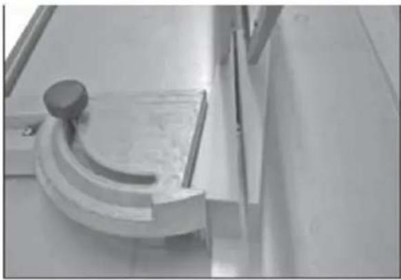
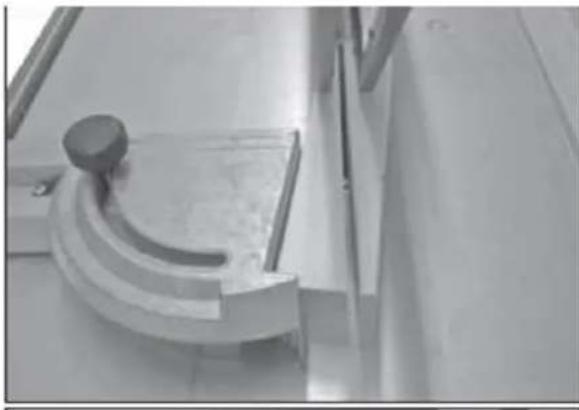
Mitre cuts (cross-cuts) and wedge-cutting
When performing this operation, the following equipment shall be used for safe working:
- Mitre gauge (ready for use by lifting onto the saw table)
• the guard of the saw blade
• the riving knife
• the insert in the table
Cross-cuts:
Mitre cuts in the range 0-90° can be carried out by pressing the workpiece to be cut firmly against the stop surface of the mitre gauge.
Wedge cuts:
To do this, set the rotary part to 0^ and secure it with the adjusting handle. Place the workpiece in the recess and saw through with even pressure.
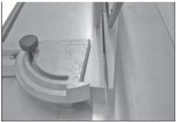
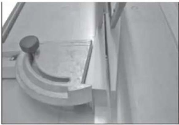
Mitre cuts (cross-cuts)
natural_image
Close-up of a metallic mechanical component with a curved bracket and mounting base (no visible text or symbols)Wedge-cutting

natural_image
Close-up of a metallic mechanical component with a curved bracket and a circular knob, mounted on a flat surface (no visible text or symbols)
CAUTION!
Feed only with the hand on the mitre gauge (hands away from the wood).

WARNING
Only remove workpieces (wedges) after the machine has come to a standstill. To do this, switch off the machine and wait for the saw blade to come to a standstill.
CLEANING, MAINTENANCE, STORGE, DISPOSAL
Cleaning

NOTE
Wrong cleaning agents can attack the varnish of the machine. Do not use solvents, nitro thinners, or other cleaning agents that could damage the machine's paint.
Observe the information and instructions of the cleaning agent manufacturer!
Regular cleaning is also a prerequisite for the safe operation of the machine and its long service life. Therefore, clean the device after each use and remove dust and dirt. Use personal protective equipment (gloves and eye protection when using compressed air). Ensure that the saw blade protection is free from wood residues and
sawdust. Cleaning is best done with compressed air or a hand brush. Also make sure that you keep the table surface free of resin.
Maintenance

WARNING
Handling the machine with the power supply up can lead to serious injuries or even death. Always disconnect the machine from the power supply before servicing or maintenance work and secure it against unintentional or unauthorized reconnection!
The machine is low-maintenance and only a few parts have to be serviced. Nevertheless, malfunctions or defects which could impair the safety of the user must be rectified immediately!
- Before each operation, check that the safety devices are in perfect condition.
- Check the connections for tightness at least once a week.
- Regularly check that the warning and safety labels on the machine are in perfect and legible condition.
Maintenance schedule
The type and degree of machine wear depend on the operating conditions. The following intervals apply when the machine is used within the specified limits:
| Interval | Components | Activity |
| Before usage | machine | Cleaning the machine |
| Before usage | machine | Removal of all loose parts/ tools |
| 1 x month | Moving parts | Greasing / lubrication of guides / gear racks / wheels |
| 1x month | break | Function test to determine that the spindles have stopped within the specified time (<10s) |
Saw blade exchange

CAUTION
- Before any manual tool change, stop the spindles, wait for standstill of all tools and prevent an unintentional restart = unplug the power supply.
• During tool change, please use cut protection gloves to avoid risk of injury.
Assembly /Disassembly of saw blade
natural_image
Exterior view of a rectangular electronic component with two labeled terminals (S), no visible text or symbols on the main body.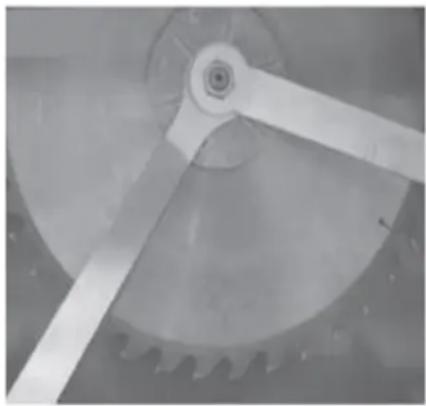
natural_image
Close-up of a mechanical gear assembly with visible teeth and central hub (no text or symbols)Loosen the two screw M8 (S) on the saw blade cover (1).
- Swivel off the saw blade cover.
- Loosen the clamping nut (M20, left-hand thread)
- Remove the saw blade and install a new one.
NOTE: Only use well sharpened, crack-free and not deformed saw blades.
Tighten clamping nut, with holding wrench.
ATTENTION: Check riving knife adjustment
Storage

NOTE
Improper storage can damage and destroy important machine parts. Store packed or unpacked parts only under the intended ambient conditions!
Disposal

Observe the national waste disposal regulations. Never dispose of the machine, machine components or equipment in residual waste. If necessary, contact your local authorities for information on the disposal options available.
If you buy a new machine or an equivalent device from your specialist retailer, he is obliged in certain countries to dispose of your old machine properly.
Troubleshooting

WARNING
Handling the machine with the power supply up can lead to serious injuries or even death.
Always disconnect the machine from the power supply before servicing or maintenance work and secure it against unintentional or unauthorized reconnection!
Many possible sources of error can be excluded in advance if the machine is properly connected to the mains. If you are unable to carry out necessary repairs properly and/or do not have the required training, always consult a specialist to correct the problem!
| Trouble | Possible cause | Solution |
| Machine does not start | Emergency stop switch to switch offswitch or a phase is brokenOverload protection is triggered.Safety fuse is blownOpen cover plate for saw blades | Turn the emergency OFF switch to the right to unlockRepair the defective circuit or the faulty phaseWait until the engine cools downReplace the fuseCover plate close |
| Burn marks on the workpiece | The blade is bluntWrong saw bladeRip-fence not parallel to saw blade | Replace the bladeReplace the bladeAdjust rip-fence |
| Low power / motor overload | Dull saw bladeOnly 2 phases installed | Replace bladeCheck power supply |
| Saw blade get loose after motor is switched off | Fixing nut too lightly fastened | Tighten fixing nut |
| Workpiece clamped while advancing | Dull bladeRiving knife thickness does not match the used blade | Replace with sharp bladeSplitting wedge thickness mustbe greater than or equal to blade thickness. |
| Wrong saw blade direction | Socket wrongly tapped | Change polarity of socket (phase-changing) |
SCHALTPLAN / WIRING DIAGRAM
1- Black
2- Grey
3- Brown
4- Blue
5- Green/Yellow
6- White
7- Red
8- Brown
9- Red
10- White
11- Brown
12- Brake
13- Thermoprotector
14- Thermoprotector
15- Motor
Parts
Delivery content
1- Machine
2- Riving knife with saw blade protection cover
3- Wheels; transport-device
4- Miter gauge
5- Push stick
6- Sliding wood
7- Key
8- Fixation knob miter gauge
9- Hook for push stick and sliding wood
10- Support base frame short
11- Rip-fence device
12- Extension table
13- Saw blade
14- Hardware
15- Rip-fence
16- Manual
Components

1- ON-OFF-switch
2- Transport handles
3- Base frame
4- Dust port collector
5- Miter gauge
6- Wheels; transport device
7- Extension table foldable

natural_image
Mechanical machine with labeled parts (13 and 14), no visible text or symbols on the device itself.8- Riving knife with saw blade protection cover
9- Saw blade
10- Main table
11- Rip fence
12- Rip fence fixation
13- Motor
14- Tool holder for push-stick, fork-wrench

natural_image
Red and silver metal machine with cutaway view, no visible text or symbolsMONTAŻ
natural_image
Technical line drawing of a mechanical assembly with vertical supports and a central cylindrical component (no text or symbols)
Montaż ramy bazowej
natural_image
Two technical diagrams showing a mechanical assembly with labeled 'S' components (no text or symbols present)Montaż ostrza piły

natural_image
Technical line drawing of a mechanical assembly with bracket and mounting features, labeled A and B (no text or symbols on the diagram itself)Montaż kątomierza
natural_image
Technical line drawing of a mechanical frame with wheels and a labeled component (no text or symbols beyond the label)natural_image
Close-up of a mechanical assembly with black components and a numbered label '1' (no readable text or symbols)natural_image
Technical line drawing of a mechanical component with a screwdriver and housing (no text or symbols)natural_image
Technical line drawing of a mechanical assembly with a saw and lever mechanism (no text or symbols)
natural_image
Technical line drawing of a mechanical assembly with wooden components and a pulley (no text or symbols)
OGŁOSZENIE
natural_image
Close-up of a mechanical component with a curved metallic part and a circular knob (no visible text or symbols)Ciecie klinowe
natural_image
Close-up of a metallic mechanical component with a curved handle and circular base, mounted on a flat surface (no visible text or symbols)
UWAGA!
natural_image
Exterior view of a rectangular electronic component with labeled 'S' and internal components (no text or symbols beyond labels)
natural_image
Close-up of a mechanical gear mechanism with visible teeth and central hub (no text or symbols)1- Maszyna
natural_image
Mechanical setup with labeled components, no visible text or symbolsnatural_image
Red and silver metal machine with a cutting board, no visible text or symbolsSHROMÁŽDĚNÍ
natural_image
Two technical diagrams showing a mechanical assembly with labeled components (S) and a close-up of a gear mechanism (no text or symbols present)

natural_image
Technical line drawing of a mechanical assembly with bracket and mounting features, labeled A and B (no text or symbols on the diagram itself)natural_image
Technical line drawing of a mechanical frame with wheels and a labeled component (no text or symbols beyond the label '1')natural_image
Close-up of a mechanical assembly with black components and a numbered label '1' (no readable text or symbols)natural_image
Technical line drawing of a mechanical device with a screwdriver and internal component (no text or symbols)natural_image
Technical line drawing of a mechanical clamp or saw assembly (no text or symbols)
natural_image
Technical line drawing of a mechanical assembly with wooden components and mounting bracket (no text or symbols)
OZNÁMENÍ
natural_image
Close-up of a metallic mechanical component with a curved bracket and mounting holes (no visible text or symbols)Klinové řezání

natural_image
Close-up of a metallic mechanical component with a curved handle and circular knob, mounted on a flat surface (no visible text or symbols)
UPOZORNĚNÍ!
natural_image
Exterior view of a rectangular electronic component with labeled 'S' points (no other text or symbols)
natural_image
Close-up of a mechanical gear assembly with visible teeth and central hub (no text or symbols)1- Stroj
natural_image
Mechanical machine with labeled parts (13 and 14), no visible text or symbols on the device itself.natural_image
Red and silver metal machine with open lid and workbench, no visible text or symbolsASSEMBLÉE
natural_image
Technical line drawing of a mechanical assembly with vertical supports and a cylindrical component (no text or symbols)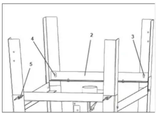
natural_image
Two technical diagrams showing a mechanical assembly with labeled 'S' components (no text or symbols present)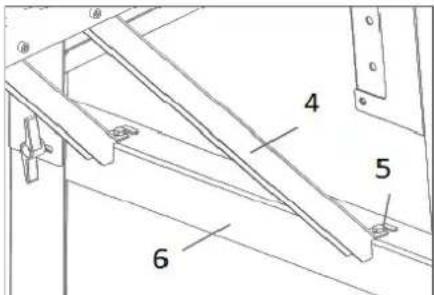

natural_image
Technical line drawing of a mechanical assembly with bracket and mounting features, labeled A and B (no text or symbols on the diagram itself)natural_image
Technical line drawing of a mechanical frame with wheels and a labeled component (no text or symbols beyond the label '1')natural_image
Close-up of a mechanical assembly with black components and a numbered label '1' (no readable text or symbols)natural_image
Technical line drawing of a mechanical component with a screwdriver and rotating shaft (no text or symbols)natural_image
Technical line drawing of a mechanical assembly with saw and bracket (no text or symbols)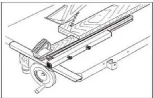
natural_image
Technical line drawing of a mechanical assembly with wooden components and mounting bracket (no text or symbols)
AVIS
natural_image
Close-up of a metallic mechanical component with a curved cutout and mounting base (no visible text or symbols)Coupe en coin

natural_image
Close-up of a mechanical component with a curved handle and circular base, mounted on a metal frame (no visible text or symbols)
ATTENTION!
natural_image
Exterior view of a rectangular electronic component with labeled 'S' and internal components (no text or symbols beyond labels)
natural_image
Close-up of a mechanical gear assembly with visible teeth and central hub (no text or symbols)natural_image
Symbol of a trash bin with crossed lines indicating no waste, and a solid black rectangle below (no text or labels)1- Machine
natural_image
Mechanical setup with labeled components, no visible text or symbols7- Table extensible pliable
natural_image
Red and silver metal machine with cutaway view, no visible text or symbolsASSEMBLAGGIO
natural_image
Technical line drawing of a mechanical assembly with vertical supports and a labeled component (no text or symbols present)
natural_image
Two technical diagrams showing a mechanical assembly with labeled components (S) and a close-up of a gear mechanism (no text or symbols present)
natural_image
Technical line drawing of a mechanical assembly with bracket and mounting features, labeled A and B (no text or symbols on the diagram itself)natural_image
Technical line drawing of a mechanical frame with wheels and a labeled component (no text or symbols beyond the label '1')natural_image
Close-up of a mechanical assembly with black components and a numbered label '1' pointing to a detail (no readable text or symbols)natural_image
Technical line drawing of a mechanical component with a screwdriver and housing (no text or symbols)natural_image
Technical line drawing of a mechanical clamp or tool assembly (no text or symbols)
natural_image
Technical line drawing of a mechanical assembly with wooden components and mounting brackets (no text or symbols)
AVVISO
natural_image
Close-up of a metallic mechanical component with a curved handle and mounting bracket (no visible text or symbols)Taglio a cuneo
natural_image
Close-up of a mechanical component with a curved handle and circular knob, mounted on a metal frame (no visible text or symbols)
ATTENZIONE!
natural_image
Exterior view of a rectangular electronic component with labeled 'S' and connection points (no text or symbols beyond labels)
natural_image
Close-up of a mechanical gear mechanism with visible teeth and central hub (no text or symbols)natural_image
Symbol of a trash bin crossed out by two crossed lines, with a solid black rectangle below (no text or labels)1- Macchina
natural_image
Mechanical setup with labeled components, no visible text or symbolsnatural_image
Red and silver metal machine with cutaway view, no visible text or symbolsASAMBLEA
natural_image
Technical line drawing of a mechanical assembly with vertical supports and a labeled component (no text or symbols present)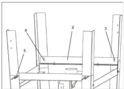
natural_image
Two technical diagrams showing a mechanical assembly with labeled components (S) and a close-up of a gear mechanism (no text or symbols present)
natural_image
Technical line drawing of a mechanical assembly with bracket and mounting features, labeled A and B (no text or symbols on the diagram itself)natural_image
Technical line drawing of a mechanical frame with wheels and a labeled component (no text or symbols beyond the label '1')natural_image
Close-up of a mechanical assembly with black components and a numbered label '1' (no readable text or symbols)natural_image
Technical line drawing of a mechanical component with a screwdriver and internal shaft (no text or symbols)natural_image
Technical line drawing of a mechanical assembly with saw and bracket (no text or symbols)
natural_image
Technical line drawing of a mechanical assembly with wooden components and a pulley (no text or symbols)
AVISO
natural_image
Close-up of a metallic mechanical component with a curved cutout and mounting base (no visible text or symbols)Corte en cuña
natural_image
Close-up of a mechanical component with a curved handle and circular base, mounted on a metal frame (no visible text or symbols)
¡ADVERTENCIA!
natural_image
Exterior view of a rectangular electronic component with labeled 'S' and two blue connectors (no text or symbols beyond labels)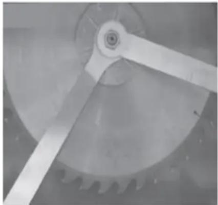
natural_image
Close-up of a mechanical gear mechanism with visible teeth and central hub (no text or symbols)natural_image
Symbol of a trash bin with crossed lines and a solid black rectangle below (no text or labels)1- Máquina
natural_image
Mechanical setup with labeled components, no visible text or symbolsnatural_image
Red and silver metal machine with cutaway view, no visible text or symbolsÖSSZESZERELÉS
natural_image
Two-panel image showing a mechanical assembly with labeled 'S' and a close-up of a rotating wheel (no text or symbols present)
natural_image
Technical line drawing of a mechanical assembly with bracket and mounting features, labeled A and B (no text or symbols on the diagram itself)natural_image
Technical line drawing of a mechanical frame with wheels and a labeled component (no text or symbols beyond the label '1')natural_image
Close-up of a mechanical assembly with black components and a numbered label '1' (no readable text or symbols)natural_image
Technical line drawing of a mechanical component with a screwdriver and housing (no text or symbols)natural_image
Technical line drawing of a mechanical assembly with saw and clamps (no text or symbols)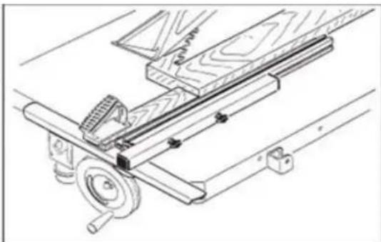
natural_image
Technical line drawing of a mechanical assembly with wooden components and a pulley (no text or symbols)
MEGJEGYZÉS
natural_image
Close-up of a metallic mechanical component with a curved bracket and mounting holes (no visible text or symbols)Ékvágás

natural_image
Close-up of a metallic mechanical component with a curved handle and circular knob, mounted on a flat surface (no visible text or symbols)
VIGYÁZAT!
natural_image
Exterior view of a rectangular electronic component with labeled 'S' and internal structure (no text or symbols beyond labels)
natural_image
Close-up of a mechanical gear assembly with visible teeth and central hub (no text or symbols)1- Gép
natural_image
Mechanical setup with black frame, wheels, and labeled components (no readable text or symbols)1- ON-OFF-kapcsoló
natural_image
Red and silver metal machine with a cutting board, no visible text or symbolsSAMLING
natural_image
Technical line drawing of a mechanical assembly with vertical supports and a labeled component (no text or symbols present)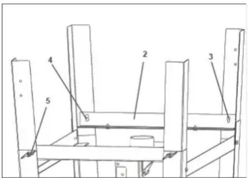
Montering af bundramme
natural_image
Two technical diagrams showing a mechanical assembly with labeled 'S' components (no text or symbols present)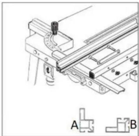
natural_image
Technical line drawing of a mechanical assembly with bracket and mounting features, labeled A and B (no text or symbols on the diagram itself)Montering af rip-fence
release = tryk klappen ned

natural_image
Technical line drawing of a mechanical frame with wheels and a labeled component (no text or symbols beyond the label '1')Montering af transporthjul
natural_image
Close-up of a mechanical assembly with black components and a numbered label '1' (no readable text or symbols)natural_image
Technical line drawing of a mechanical component with a screwdriver and housing (no text or symbols)natural_image
Technical line drawing of a mechanical assembly with saw and clamps (no text or symbols)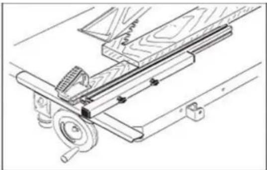
natural_image
Technical line drawing of a mechanical assembly with wooden components and a pulley (no text or symbols)
BEMÆRK
natural_image
Close-up of a metallic mechanical component with a curved bracket and mounting holes (no visible text or symbols)Kile-skæring

natural_image
Close-up of a metallic mechanical component with a curved bracket and a circular knob, mounted on a flat surface (no visible text or symbols)
OBS!
natural_image
Exterior view of a rectangular electronic component with labeled 'S' and two blue connectors (no text or symbols beyond labels)
natural_image
Close-up of a mechanical gear assembly with visible teeth and central hub (no text or symbols)Løsn de to skruer M8 (S) på savklingens dæksel (1).
1- Maskine
natural_image
Mechanical machine with labeled parts (13 and 14), no visible text or symbols on the device itself.
natural_image
Red and silver metal machine with cutaway view, no visible text or symbolsKOKOONPANO
natural_image
Technical line drawing of a mechanical assembly with vertical supports and a cylindrical component (no text or symbols)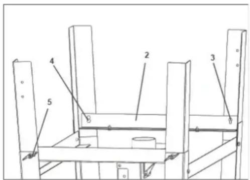
natural_image
Two technical diagrams showing a mechanical assembly with labeled components (S) and a close-up of a gear mechanism (no text or symbols present)
natural_image
Technical line drawing of a mechanical assembly with bracket and mounting features, labeled A and B (no text or symbols on the diagram itself)natural_image
Technical line drawing of a mechanical frame with wheels and a labeled component (no text or symbols beyond the label '1')natural_image
Close-up of a mechanical assembly with black components and a numbered label '1' (no readable text or symbols)natural_image
Technical line drawing of a mechanical component with a screwdriver and housing (no text or symbols)natural_image
Technical line drawing of a mechanical assembly with saw and clamping components (no text or symbols)
natural_image
Technical line drawing of a mechanical assembly with wooden components and a pulley (no text or symbols)
HUOMAUTUS
natural_image
Close-up of a metallic mechanical component with a curved bracket and mounting base (no visible text or symbols)Kiilaleikkaus
natural_image
Close-up of a metallic mechanical component with a curved handle and circular knob, mounted on a flat surface (no visible text or symbols)
HUOMIO!
natural_image
Exterior view of a rectangular electronic component with two labeled terminals (S), no visible text or symbols on the main body.
natural_image
Close-up of a mechanical gear assembly with visible teeth and central hub (no text or symbols)1- Kone
natural_image
Mechanical machine with labeled parts (13 and 14), no visible text or symbols on the device itself.natural_image
Red and silver metal machine with cutaway view, no visible text or symbolsMONTAGE
1. Controle van de leveringsomvang
natural_image
Technical line drawing of a mechanical assembly with vertical supports and a central cylindrical component (no text or symbols)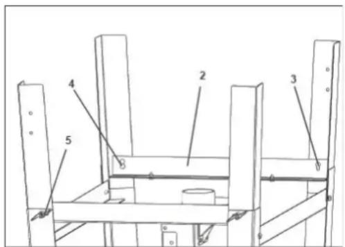
natural_image
Two technical diagrams showing a mechanical assembly with labeled 'S' components (no text or symbols present)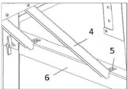
Montage van tafelverlenging

natural_image
Technical line drawing of a mechanical assembly with bracket and mounting features, labeled A and B (no text or symbols on the diagram itself)Montage van de rip-fence
Montage van verstekgeleider
natural_image
Technical line drawing of a mechanical frame with wheels and a labeled component (no text or symbols beyond the label '1')natural_image
Close-up of a mechanical assembly with black components and a numbered label '1' (no readable text or symbols)natural_image
Technical line drawing of a mechanical component with a screwdriver and housing (no text or symbols)natural_image
Technical line drawing of a mechanical assembly with saw and lever components (no text or symbols)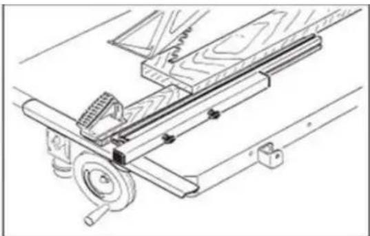
natural_image
Technical line drawing of a mechanical assembly with wooden components and a pulley (no text or symbols)
KENNISGEVING
natural_image
Close-up of a metallic mechanical component with a curved bracket and mounting holes (no visible text or symbols)Wigvormig snijden
natural_image
Close-up of a metallic mechanical component with a curved handle and circular knob, mounted on a flat surface (no visible text or symbols)
LET OP!
natural_image
Pure diagram of a rectangular object with labeled 'S' and two blue arrows pointing to its edges (no text or symbols beyond labels)
natural_image
Close-up of a mechanical gear mechanism with visible teeth and central hub (no text or symbols)1- Machine
natural_image
Mechanical setup with labeled components, no visible text or symbols1- AAN-UIT-schakelaar
2- Transport handgrepen
3- Basisframe
4- Stofafzuiging
5- Verstekgeleider
6- Wielen; transportmiddel
natural_image
Red and silver metal machine with a cutting board, no visible text or symbolsFORSAMLING
natural_image
Two technical diagrams showing a mechanical assembly with labeled 'S' components (no text or symbols present)
natural_image
Technical line drawing of a mechanical assembly with bracket and mounting features, labeled A and B (no text or symbols on the diagram itself)natural_image
Technical line drawing of a mechanical frame with wheels and a labeled component (no text or symbols beyond the label '1')natural_image
Close-up of a black mechanical hinge with a white strap and blue pointer, no visible text or symbolsnatural_image
Technical line drawing of a mechanical component with a screwdriver and circular component (no text or symbols)natural_image
Technical line drawing of a mechanical clamp or saw assembly (no text or symbols)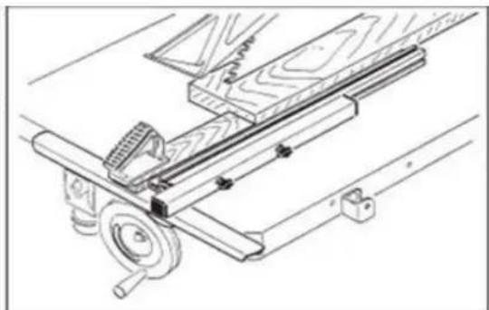
natural_image
Technical line drawing of a mechanical assembly with wooden components and mounting bracket (no text or symbols)
MERKNAD
Ved tverrkapping av rundvirke er det nødvendig med en mal eller en holdeanordning for å sikre arbeidsstykket mot vridning og bruk av egnet sagblad er nødvendig.
natural_image
Close-up of a metallic mechanical component with a curved bracket and mounting base (no visible text or symbols)Kileskjæring
natural_image
Close-up of a metallic mechanical component with a curved bracket and a circular knob, mounted on a flat surface (no visible text or symbols)
OBS!!!
natural_image
Exterior view of a rectangular electronic component with two labeled points 'S' (no other text or symbols visible)
natural_image
Close-up of a mechanical gear assembly with visible teeth and central hub (no text or symbols)1- Maskin
2- Spaltekniv med sagbladbeskyttelsesdeksel
3- Hjul; transport-enhet
4- Gjæringsmåler
5- Skyv pinne
6- Glidetre
7- Nøkkel
natural_image
Mechanical machine with labeled parts (13 and 14), no visible text or symbols on the device itself.1- PÅ-AV-bryter
2- Transporthåndtak
3- Grunnramme
4- Støvportsamler
5- Gjæringsmåler
natural_image
Red and silver metal machine with a cutting board, no visible text or symbolsMONTERING
natural_image
Two technical diagrams showing a mechanical assembly with labeled components (S) and a close-up of a gear mechanism (no text or symbols present)
natural_image
Technical line drawing of a mechanical assembly with bracket and mounting features, labeled A and B (no text or symbols on the diagram itself)natural_image
Technical line drawing of a mechanical frame with wheels and a labeled component (no text or symbols beyond the label '1')natural_image
Close-up of a mechanical assembly with black components and a numbered label '1' (no readable text or symbols)natural_image
Technical line drawing of a mechanical component with a screwdriver and housing (no text or symbols)natural_image
Technical line drawing of a mechanical clamp or saw assembly (no text or symbols)
natural_image
Technical line drawing of a mechanical assembly with wooden components and mounting bracket (no text or symbols)
VARSEL
natural_image
Close-up of a metallic mechanical component with a curved bracket and mounting holes (no visible text or symbols)Kilskärning

natural_image
Close-up of a metallic mechanical component with a curved bracket and a circular knob, mounted on a flat surface (no visible text or symbols)
OBS!
natural_image
Exterior view of a rectangular electronic component with labeled 'S' and two blue connectors (no text or symbols beyond labels)
natural_image
Close-up of a mechanical gear assembly with visible teeth and central hub (no text or symbols)1- Maskin
natural_image
Mechanical machine with labeled parts (13 and 14), no visible text or symbols on the device itself.natural_image
Red and silver metal machine with cutaway view, no visible text or symbolsCONJUNTO
natural_image
Technical line drawing of a mechanical assembly with vertical supports and a labeled component (no text or symbols present)
natural_image
Two technical diagrams showing a mechanical assembly with labeled components (S) and a close-up of a gear mechanism (no text or symbols present)
natural_image
Technical line drawing of a mechanical assembly with bracket and mounting features, labeled A and B (no text or symbols on the diagram itself)natural_image
Technical line drawing of a mechanical frame with wheels and a labeled component (no text or symbols beyond the label '1')Montagem de rodas de transporte
natural_image
Close-up of a mechanical assembly with black components and a numbered label '1' (no readable text or symbols)natural_image
Technical line drawing of a mechanical component with a screwdriver and circular component (no text or symbols)natural_image
Technical line drawing of a mechanical tool or saw assembly (no text or symbols present)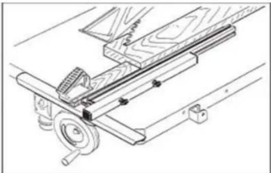
natural_image
Technical line drawing of a mechanical assembly with wooden components and a pulley (no text or symbols)
PERCEBER
natural_image
Close-up of a mechanical component with a curved metallic part and a circular knob (no visible text or symbols)Corte em cunha

natural_image
Close-up of a metallic mechanical component with a curved handle and circular base, mounted on a flat surface (no visible text or symbols)
ATENÇÃO!
natural_image
Exterior view of a rectangular electronic component with labeled 'S' and internal components (no text or symbols beyond labels)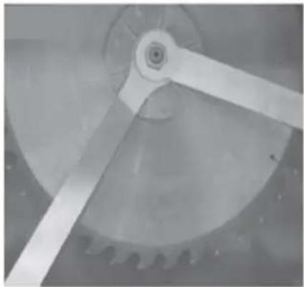
natural_image
Close-up of a mechanical gear mechanism with visible teeth and central hub (no text or symbols)1- Máquina
natural_image
Mechanical setup with labeled components, no visible text or symbols1- Interruptor liga/desliga
2- Alças de transporte
3- Estrutura base
4- Coletor de pó
5- Medidor de esquadria
natural_image
Red and silver metal machine with open lid and workpiece, no visible text or symbolsMONTÁŽ
natural_image
Two technical diagrams showing a mechanical assembly with labeled components (S) and a close-up of a gear mechanism (no text or symbols present)
natural_image
Technical line drawing of a mechanical assembly with bracket and mounting features, labeled A and B (no text or symbols on the diagram itself)natural_image
Technical line drawing of a mechanical frame with wheels and a labeled component (no text or symbols beyond the label)natural_image
Close-up of a mechanical assembly with black components and a numbered label '1' (no readable text or symbols)natural_image
Technical line drawing of a mechanical component with a screwdriver and housing (no text or symbols)natural_image
Technical line drawing of a mechanical clamp or saw assembly (no text or symbols)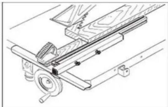
natural_image
Technical line drawing of a mechanical assembly with wooden components and mounting bracket (no text or symbols)
UPOZORNENIE
natural_image
Close-up of a metallic mechanical component with a curved bracket and mounting holes (no visible text or symbols)Klinové rezanie

natural_image
Close-up of a metallic mechanical component with a curved handle and circular knob, mounted on a flat surface (no visible text or symbols)
UPOZORNENIE!
Podávajte iba rukou na mierke pokosu (ruky preč od dreva).

POZOR
natural_image
Exterior view of a rectangular electronic component with labeled 'S' points (no other text or symbols)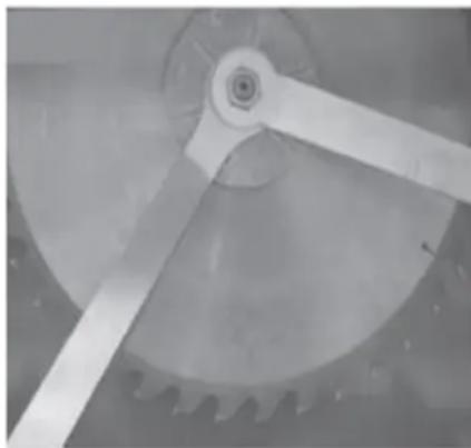
natural_image
Close-up of a mechanical gear assembly with visible teeth and central hub (no text or symbols)Uvolnite dve skrutky M8 (S) na kryte pílového kotúča (1).
1- Stroj
natural_image
Mechanical device with labeled parts (13, 14), no visible text or symbols on the structure itself1- ON-OFF-vypínač
natural_image
Red and silver machine tool with metal frame and workpiece, no visible text or symbolsМОНТАЖ
natural_image
Two technical diagrams showing a mechanical assembly with labeled 'S' and a close-up of a rotating wheel (no text or symbols present)Монтаж на трион

natural_image
Technical line drawing of a mechanical assembly with bracket and mounting features, labeled A and B (no text or symbols on the diagram itself)Монтаж на ограда
natural_image
Technical line drawing of a mechanical frame with wheels and a labeled component (no text or symbols beyond the label '1')Монтаж на транспортни колела
natural_image
Close-up of a black mechanical hinge with a white tassel, showing structural components and a numbered label '1' (no text or symbols on the main subject)natural_image
Technical line drawing of a mechanical component with a screwdriver and housing (no text or symbols)natural_image
Technical line drawing of a mechanical assembly with a saw and lever mechanism (no text or symbols)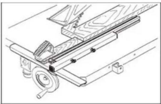
natural_image
Technical line drawing of a mechanical assembly with wooden components and mounting brackets (no text or symbols)
ЗАБЕЛЕЖКА
natural_image
Close-up of a metallic mechanical component with a curved cutout and mounting base (no visible text or symbols)Нарязване на клин

natural_image
Close-up of a mechanical component with a curved handle and mounting bracket (no visible text or symbols)
ВНИМАНИЕ!
natural_image
Exterior view of a rectangular electronic component with labeled 'S' and two blue connectors (no text or symbols beyond labels)
natural_image
Close-up of a mechanical gear mechanism with visible teeth and central shaft (no text or symbols)natural_image
Symbol of a trash bin with crossed lines and a solid black rectangle below (no text or labels)1- машина
natural_image
Mechanical setup with labeled components, no visible text or symbols1- ON-OFF-ключ
natural_image
Red and silver machine tool with metal frame and workpiece, no visible text or symbolsΣΥΝΕΛΕΥΣΗ
natural_image
Technical line drawing of a mechanical assembly with vertical supports and a labeled component (no text or symbols present)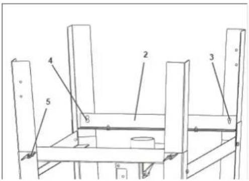
natural_image
Two technical diagrams showing a mechanical assembly with labeled 'S' and a close-up of a gear mechanism (no text or symbols present)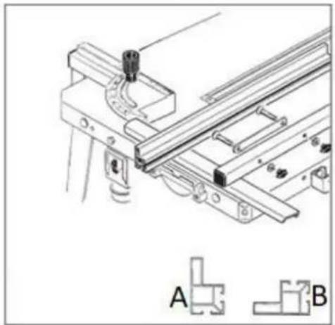
natural_image
Technical line drawing of a mechanical assembly with bracket and mounting features, labeled A and B (no text or symbols on the diagram itself)natural_image
Technical line drawing of a mechanical frame with wheels and a labeled component (no text or symbols beyond the number 1)natural_image
Close-up of a mechanical assembly with black and white components, no visible text or symbolsnatural_image
Technical line drawing of a mechanical component with a screwdriver and circular component (no text or symbols)natural_image
Technical line drawings of a mechanical assembly, showing front and side views with no visible text or symbols
ANAKOINΩΣΗ
natural_image
Close-up of a mechanical component with a curved metallic part and a circular knob (no visible text or symbols)Σφηνοκόψιμο
natural_image
Close-up of a metallic mechanical component with a curved handle and circular end, mounted on a flat surface (no visible text or symbols)
ΠΡΟΣΟΧΗ!
natural_image
Pure electrical circuit lines without any symbols
natural_image
Close-up of a mechanical gear mechanism with visible teeth and central hub (no text or symbols)1- Mηχανή
natural_image
Mechanical setup with labeled components, no visible text or symbols1- Διακόπτης ON-OFF
2- Λαβές μεταφοράς
3- Πλαίσιο βάσης
natural_image
Red and silver metal machine with open lid and workpiece, no visible text or symbolsSKUPŠTINA
Sastavljanje osnovnog okvira
- Podignite donju potpornu nogu (1).
- Montirajte kratki križni nosač (2), poravnajte montažnu rupu (3) i zategnite poluokrugle vijke (4) s gumbima za zaključavanje (5).
- Zatim postavite stroj
natural_image
Two technical diagrams showing a mechanical assembly with labeled components (S) and a close-up of a gear mechanism (no text or symbols present)Montaža rascjepnog noža sa zaštitnim poklopcem za oštricu pile
- Postavite već montirani zaštitni poklopac lista pile s rascjepnim nožem odozgo između vodilice i stezne ploče.
- Postavite razmak između noža za rascjep i lista pile na 3 - 8 mm (a) i zategnite steznu ploču s četiri vijka sa šesterokutnom glavom i podloškama (2).
BILJEŠKA:
- Poklopac je montiran spreman za rad i ne smije se skidati za rad.
natural_image
Technical line drawing of a mechanical assembly with bracket and mounting features, labeled A and B (no text or symbols on the diagram itself)Montaža rip-ograde
- Pričvrstite steznu napravu (1) za rascjep (graničnik) na ploču stola s dva vijka M6 s ravnom glavom, dvije podloške i dvije matice.
- Pričvrstite pričvrsnu ploču (2) na graničnik (3) pomoću dva M6 vijka, dvije podloške i dvije matice.
natural_image
Technical line drawing of a mechanical frame with wheels and a labeled component (no text or symbols beyond the label '1')Montaža transportnih kotača
Sastavite skupinu kotača (1) na donju potpornu nogu pomoću vijaka i matica.

natural_image
Close-up of a mechanical assembly with black components and a numbered label '1' (no readable text or symbols)Montaža kuke za alate za guranje
Pričvrstite kuku na okvir pomoću matice
natural_image
Technical line drawing of a mechanical component with a screwdriver and housing (no text or symbols)natural_image
Technical line drawing of a mechanical assembly with saw and lever components (no text or symbols)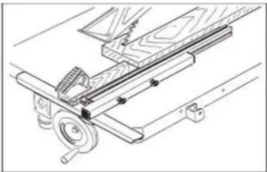
natural_image
Technical line drawing of a mechanical assembly with wooden components and a pulley (no text or symbols)
OBAVIJEST
Kod poprečnog rezanja oblog drva potrebna je šablona ili držač kako bi se obradak osigurao od uvijanja, a potrebna je i upotreba odgovarajućeg lista pile.