SLT-2000 - Industrial lift table MSW - Free user manual and instructions
Find the device manual for free SLT-2000 MSW in PDF.

User questions about SLT-2000 MSW
0 question about this device. Answer the ones you know or ask your own.
Ask a new question about this device
Download the instructions for your Industrial lift table in PDF format for free! Find your manual SLT-2000 - MSW and take your electronic device back in hand. On this page are published all the documents necessary for the use of your device. SLT-2000 by MSW.
USER MANUAL SLT-2000 MSW
STATIONARY LIFT TABLE
| DE | Produktname | SCHEREN HUBTISCH |
| EN | Product name | STATIONARY LIFT TABLE |
| PL | Nazwa produktu | STÓŁ PODNOŚNY NOŻYCOWY |
| CZ | Název výrobku | STACIONÁRNÍ ZDVIHACÍ STÜL |
| FR | Nom du produit | TABLE ELEVATRICE STATIONNAIRE |
| IT | Nome del prodotto | TAVOLO ELEVATORE FISSO |
| ES | Nombre del producto | MESA ELEVADORA ESTACIONARIA |
| HU | Termék neve | ÁLLÓ EMELŐASZTAL |
| DA | Produktnavn | STATIONÆRT L∅FTEBORD |
| FI | Tuotteen nimi | KIINTEÄ NOSTOPÖYTÄ |
| NL | Productnaam | STATIONAIRE HEFTAFEL |
| NO | Produktnavn | STASJONÆRT L∅FTEBORD |
| SE | Produktnamn | STATIONÄR LYFTBORD |
| PT | Nome do produto | MESA ELEVATÓRIA ESTACIONÁRIA |
| SK | Názov produktu | STACIONÁRNY ZDVIHACÍ STÔL |
| BG | Име на продукта | СТАЦИОНАРНА ПОВДИГАША МАСА |
| EL | Όνομα προϊόντος | ΣΤΑΘΕΡΟΣ ANYΨΩΤΙΚΟΣ ΠΙΝΑΚΑΣ |
| HR | Naziv proizvoda | STACIONARNI PODIZNI STOL |
| LT | Produkto pavadinimas | STACIONARI KELIAMOJI LENTELÉ |
| RO | Numele produsului | MASÄ DE RIDICARE STAȚIONARÄ |
| SL | Ime izdelka | STACIONARNA DVIGALNA MIZA |
| DE Modell | EN Product model | PL Model produktu | CZ Model výrobku | FR Modèle | IT Modello | ES Modelo | HU Modell | DA Model | FI Tuotteen malli | NL Productmodel | NO Produktmodell | SE Produktmodell | PT Modelo do produto | SK Model | BG Модел на продукт | EL Movtéλo προϊόντος | HR Model proizvoda | LT: Gaminio modelis | RO: Model de produs | SL: Model izdelka | MSW-SLT-1000MSW-SLT-2000 | |
| DE Hersteller | EN Manufacturer | PL Producent | CZ Výrobce | FR Fabricant | IT Produttore | ES Fabricante | HU Termelő | DA Producent | FI Valmistaja | NL Producent | NO Produsent | SE Tillverkare | PT Fabricante | SK Výrobca | BG Производител | EL Κατασκευαστής | HR Proizvođač | LT Gamintojas | RO Producător | SL Proizvajalec | expondo Polska sp. z o.o. sp. k. | |
| DE Anschrift des Herstellers | EN Manufacturer Address | PL Adres producenta | CZ Adresa výrobce | FR Adresse du fabricant | IT Indirizzo del produttore | ES Dirección del fabricante | HU A gyártó címe | DA Producentens adresse | FI Valmistajan osoite | NL Adres producent | NO Produsentens adresse | SE Tillverkarens adress | PT Endereço do fabricante | SK Adresa výrobcu | BG Адрес на производителя | EL: Διεύθυνση κατασκευαστή | HR Adresa proizvođača | LT Gamintojo adresas | RO Adresa producătorului | SL Naslov proizvajalca | ul. Nowy Kisielin – Innowacyjna 7, 66-002 Zielona Góra | Poland, EU | |

This User Manual has been translated for your convenience using machine translation. Reasonable efforts have been made to provide an accurate translation; however, no automated translation is perfect nor is it intended to replace human translators. The official User Manual is the English version. Any discrepancies or differences created in the translation are not binding and have no legal effect for compliance or enforcement purposes. If any questions arise related to the accuracy of the information contained in the User Manual, please refer to the English version of those contents which is the official version.
Technical data
| Parameter description Parameter value | ||
| Product name | Stationary lift table | |
| Model | MSW-SLT-1000 | MSW-SLT-2000 |
| Rated voltage [V~] / frequency [Hz] | 400 / 50 | |
| Rated power [W] | 750 | 1500 |
| Protection class | I | |
| Protection rating IP | IP55 | |
| Engine speed [rpm] | 1400 | |
| Insulation class | F | |
| Duty cycle | S1 | |
| Dimensions [width x depth x height; mm] | 820 x 1300 x 205 | 850 x 1300 x 230 |
| Weight [kg] | 180 | 260 |
| Min. height [cm] | 20.5 | 23 |
| Max. lifting height [cm] | 99 | 100 |
| Maximum load capacity [kg] | 1000 | 2000 |
| Table size [mm] | 1300 x 820 | 1300 x 850 |
- Read & thoroughly understand the Instruction Manual completely before using. Follow all safety instructions strictly.
- It is necessary to check all safety devices before operation.
• Make sure that there are no obstacles in the working area. - Do not put foot or hand in scissor-mechanism or through frame.
- Screw the lifting eyes on the base frame before working on the lift table.
- Do not overload the lift table. Load should be distributed on the table according to relevant load distribution chart.
- Pay attention that the if local voltage and frequency is as same as the input specification of the lift table.
• Use the lift table on flat and solid ground. - All the electrical connection and disconnection operations must be carried out by skilled and competent personal.
- While operation, it is forbidden to contact the moving parts of the lift table.
- While the lift table moving, it is forbidden to adjust or to move the load.
- It is forbidden to lift the load, that can do harm to a person or other object.
- It is forbidden to operate the lift table while a person is under the table.
- Do not adjust the safety valve of hydraulic power pack.
- It is forbidden to operate the lift table even if there is small structure distortion.
- Do not use in an explosive or flammable place.
- The lift table is a movable lifter designed to lift or lower rated load. Do not use it for other purpose.
- Do not allow a person to operate the lift table, who does not understand its operation.
- It is forbidden to change the lift table without manufacturer's written admission.
• Use only spare parts designated by manufacturer.
- Make sure to keep a distance between the table and ambient objects enough to operate the lift table safely.
- Keep the hydraulic system under clean and safe condition.
- The hydraulic power pack features an electric lowering control. The coils must be fed with the required voltage as described on those coils. The power supply voltage should not exceed ±10% of the rated required voltage.
• Always do maintenance and routine check while the lift table is unloaded.
- The lift table is not waterproof and should be installed and used indoors in a dry environment only.
Note: maximum load refers to the load being uniformly distributed over the entire platform area. In accordance with EN 1570 safety requirements for lifting tables, the basic requirements are:
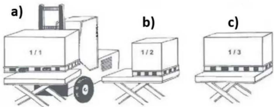
a) 100% of the rated load (maximum load) uniformly distributed over the entire platform area.
b) 50% of the rated load (maximum load) uniformly distributed over half the length of the platform.
c) 33% of the rated load (maximum load) uniformly distributed over half width of the platform.
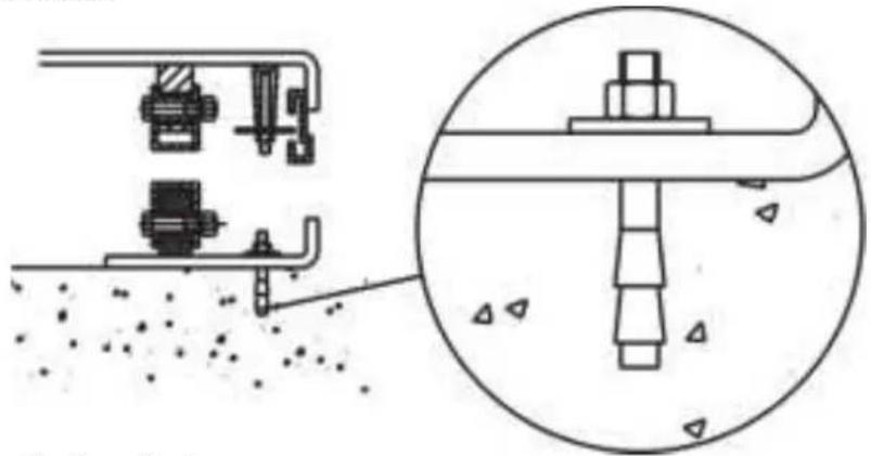
Installation on the floor/ground or in a pit
Double or triple vertical scissor tables must be fixed securely to the floor/ground by means of expander bolts or similar:
natural_image
Technical diagram showing mechanical assembly with a magnified inset of a bolted joint (no text or labels)Mechanical/electrical installation
- The base frame of the lift table is not as standard self-supporting. It is important that the floor is flat and stable and that the installation area or pit, when necessary, is well drained.
• Utilize a lifting sling through the scissor package. - Tie the base frame to the platform or the scissor mechanism.
- Place the table into the desired position.
- Turn the fixed arm end to the side where the load will be moved on or off at upper level. See picture below.
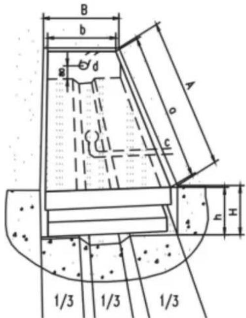
A. Pit length = a+30mm
B. Pit width = b+30mm
H. Pit depth = closed height of table + 5mm
a. Platform length
b. Platform width
c. Drainage hole (when required)
d. Tube for external cables and hoses
h. Lowest height
- Check the operation of the safety frame on all sides.
- The control device should be positioned so that the operator has a clear view over the lift table and the load at all times when the lift is operated.
Daily inspection
Caution: do not use the lift table if a malfunction or fault is present!
- Check for scratches, bend parts or crack on the lift table.
- Check for a smooth movement of the table.
- Check if there is any hydraulic oil leak.
- Check the vertical creep of the table.
- Check if all the bolts and nuts are firmly tightened.
Operation
- Loading:
- The maximum capacity of the product should not be exceeded. Load should be distributed on the table evenly.
-
Lifting:
-
Screw and loose emergency stop switch (if pressed down).
- Push and keep pushed the UP-button and the table starts lifting the load.
- Loose the UP-button and the table stops working.
-
Note: if the table reaches its highest position it will stop automatically.
-
Lowering:
-
Push the DOWN-button and the table will lower.
- Loose the DOWN-button and the table will stop.
• Note: if the table reaches its lowest position it will stop automatically.
4. Emergency stop:
- Push down the emergency stop switch and the movement of table stops.
5. Transport:
- If there is a need to move the product form its place, than it should be lifted with help of the ringbolts (included) screwed into the marked holes in the table surface.
Maintenance
- Do routine check of fasteners, and check for oil leaks.
• Do routine check of the function of the lift table.
• Before service the lift table, make sure to turn off the electric power supply.
• After service it is necessary to check the function of the lift table again.
• ONLY a qualified personnel can do service work.
- Do routine check of the micro-switches on the safety guard.
- Do routine check of the hydraulic system by listening its noise, touch motor's surface. Caution: It is necessary to turn off the AC power supply before touch motor's surface.
• Pay attention to clean or even replace the oil filter after operating for a longer period of time.
- Appropriate lubrication is necessary to make the lift table work easily and have a prolonged service life.
• Following table is recommended to service the lift table periodically:
| Content | After every 500 hours working or every 3 months | After every 2000 hours working or every year |
| Check the oil level in the oil tank. | ☆ | |
| Check the condition of oil filter | ☆ | |
| Fasten all the connecting parts again | ☆ | |
| Check wear and tear of pressure oil | ☆ | |
| Check hydraulic cylinder | ☆ | |
| Tighten main parts again | ☆ | |
| Check the function of micro-switches | ☆ | |
| Check whole working state of the lift | ☆ | |
| Lubricate all the joints and pivot points | ☆ | |
| Check wear and tear of all axial bushes | ☆ | |
| Replace hydraulic oil for the first time | Accumulated working 10 hours | |
| Replace hydraulic oil | ☆ | |
| Check for hydraulic oil leaks | ☆ | |
Greasing points
- Piston rod bearing
- Lower running wheel
- Lower arm fixing
- Arm center
- Upper arm fixing
- Upper running wheel
When greasing the bearings the table must not be loaded! When determining oil levels, bear in mind that the tank contains the greatest amount when the lift table is in its lowest position. Hydraulic oil must be treated as dangerous waste!
Troubleshooting
| Trouble | Possible cause | Solution |
| Table cannot lift while motor works normally | Eyebolt has not been removedAC voltage phases mistakenElectromagnetic valve dysfunctionsThe table is overloaded | Remove eyeboltCorrect AC voltage phraseCheck the function of electromagnetic valve and repair itRemove excessive load |
| Table cannot lift and motor does not work | Lowering limit switch (if existed) damaged | Replace limit switch |
| Table cannot be lowered | Lowering limit switch or micro-switch on safety guard damagedElectromagnetic valve dysfunctionSafety guard worksPCB failure | Replace lowering limit switch or microswitch.Check the function of electromagnetic valve and repair itStrike the UP button slightlyReplace PCB |
| Table's legs go over limit position (if existed) while table lowers | Internal leaking in electromagnetic valvePacking damaged in hydraulic cylinder | Repair electromagnetic valve or if necessary replace itCheck and replace packing |
| Table cannot reach the highest position | Not enough hydraulic oil in the systemLimit switch damaged | Add enough oilCheck and repair limit switch. If necessary, replace it |

natural_image
Technical diagram showing mechanical assembly with a magnified inset of a bolted joint (no text or labels)natural_image
Technical diagram showing mechanical assembly with a magnified inset of a bolted joint (no text or labels)natural_image
Technical diagram showing mechanical assembly and component alignment (no text or symbols)natural_image
Technical diagram showing mechanical assembly and cross-section view of a bolted joint (no text or labels)natural_image
Technical diagram showing mechanical assembly with a magnified inset of a bolted joint (no text or labels)natural_image
Technical diagram showing mechanical assembly and cross-section view of a bolted joint (no text or labels)natural_image
Technical diagram showing mechanical assembly and cross-section view of a bolted joint (no text or labels)Mekanisk/elektrisk installation
natural_image
Technical diagram showing mechanical assembly and component alignment (no text or symbols)Mekanisk/elektrisk installation
natural_image
Technical diagram showing mechanical assembly and component alignment (no text or symbols)B. Šírka jamky = b+30mm
H. Híbka jamy = uzavretá výška stola+5mm
a. Dížka platformy
b. Šírka platformy
c. Odtokový otvor (ak je to potrebné)
d. Rúrka pre externé káble a hadice
h. Najnižšia výška
natural_image
Technical diagram showing mechanical assembly with a magnified inset of a bolted joint (no text or labels)natural_image
Technical diagram showing mechanical assembly with a magnified inset of a bolted joint (no text or labels)natural_image
Technical diagram showing mechanical assembly and component alignment (no text or symbols)Strojarska/elektro instalacija
- Osnovni okvir podiznog stola nije standardno samonosiv. Važno je da je pod ravan i stabilan i da je prostor za ugradniu ili jama, kada je potrebno, dobro drenirana.
- Upotrijebite remen za podizanje kroz paket škara.
• Zavežite temeljni okvir za platformu ili mehanizam za škare.
• Postavite stol u željeni položaj.
B. Širina jame = b+30mm
H. Dubina jame = zatvorena visina stola + 5 mm
a. Dužina platforme
b. Širina platforme
c. Drenažni otvor (ako je potrebno)
natural_image
Technical diagram showing mechanical assembly with a magnified inset of a bolted joint (no text or labels)1. Stūmoklio strypo guolis
natural_image
Technical diagram showing mechanical assembly and component alignment (no text or symbols)Instalatie mecanica/electrica
natural_image
Technical diagram showing mechanical assembly and component alignment (no text or symbols)Strojna/elektro inštalacija
For the disposal of the device please consider and act according to the national and local rules and regulations.
CONTACT
expondo Polska sp. z o.o. sp. k.