CSMH-100 - Vacuum packaging machines MSW - Free user manual and instructions
Find the device manual for free CSMH-100 MSW in PDF.

User questions about CSMH-100 MSW
0 question about this device. Answer the ones you know or ask your own.
Ask a new question about this device
Download the instructions for your Vacuum packaging machines in PDF format for free! Find your manual CSMH-100 - MSW and take your electronic device back in hand. On this page are published all the documents necessary for the use of your device. CSMH-100 by MSW.
USER MANUAL CSMH-100 MSW
This User Manual has been translated for your convenience using machine translation. Reasonable efforts have been made to provide an accurate translation; however, no automated translation is perfect nor is it intended to replace human translators. The official User Manual is the English version. Any discrepancies or differences created in the translation are not binding and have no legal effect for compliance or enforcement purposes. If any questions arise related to the accuracy of the information contained in the User Manual, please refer to the English version of those contents which is the official version.
Technical data
| Parameter description | Parameter value |
| Product name | Continuous Sealing Machine |
| Model | MSW-CSMH-100 |
| Rated voltage [V~] / Frequency [Hz] | 230 / 50 |
| Rated power [W] | 500 |
| Temperature range [°C] | 0-300 |
| Dimensions [Width x Depth x Height; mm] | 820 x 500 x 300 |
| Weight [kg] | 18.7 |
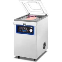
1. Product Purpose:
This product is designed for plastic film sealing and bag making. It is widely applicable in industries such as food, pharmaceuticals, chemicals, daily products, seeds, and more. It serves as an ideal sealing solution for batch product packaging in factories, stores, and similar environments.
2. Safety Notes:
1. Power Supply:
- Confirm the correct power supply type for the machine to avoid any errors.
- The machine uses a single-phase three-wire power. The yellow and green wires are grounding wires and must be grounded independently and securely. They should not be removed.
2. Prevent Pressure on Power Lines:
- Avoid placing pressure on power lines, and neatly store them when not in use.
3. Electrical Safety:
- Once the power is switched on, avoid touching any electrical devices.
- Do not touch any moving parts while the machine is operating to prevent injury.
- Avoid contact with the heating block during operation to prevent burns.
4. Operating Conditions:
- Do not use the machine in corrosive or humid environments.
5. Modification Warning:
- Do not change any parts of the machine without proper authorization.
6. Cleaning and Maintenance:
- Keep the machine clean both inside and outside. Remove any debris or particles from the sealing tape regularly.
7. Power Off When Not in Use:
- Switch off the machine when it is not being used.
8. Manual Reference:
- Keep the user manual handy for future reference.
3. Performance Features:
1. Electronic Constant Temperature Control:
- The machine uses an electronic constant temperature control device and a stepless adjustment driving mechanism.
- It is capable of sealing plastic film bags made from various materials and can be used with various packaging flow lines without a limit on sealing length.
EN
- The machine is known for its high continuous sealing efficiency, reliable sealing quality, reasonable structure, and convenient operation.
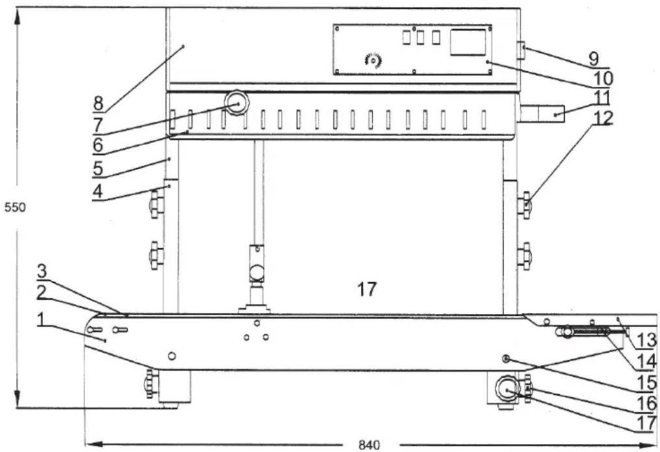
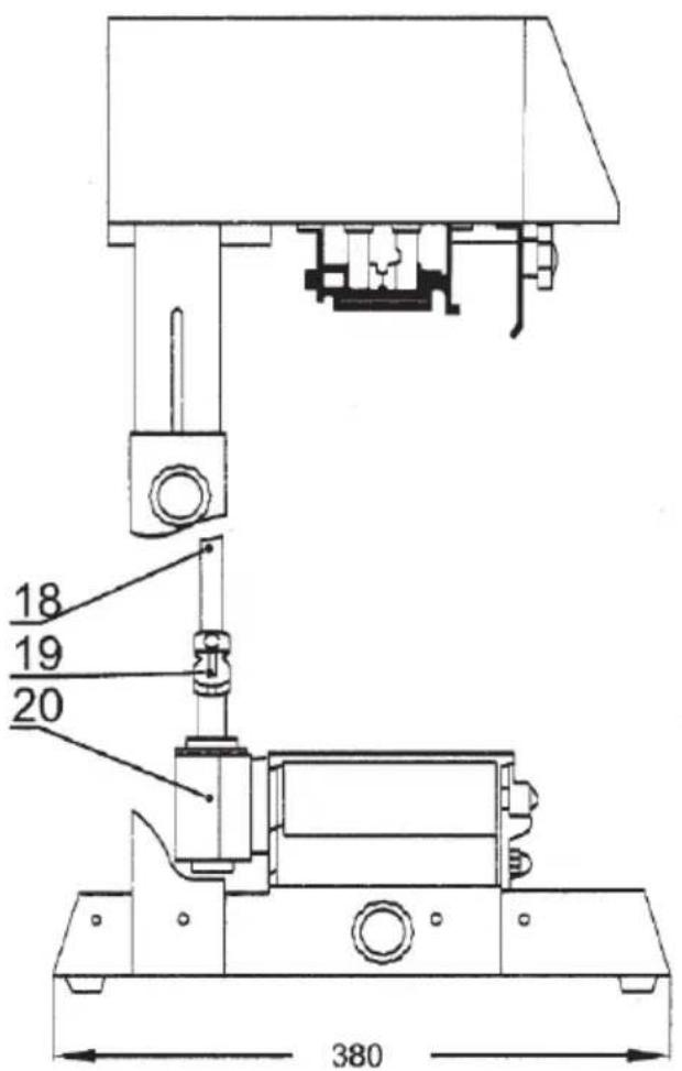
4. Main structure and working principle
EN
- Conveying platform
- Conveyor belt front wheel
- Conveyor belt
- Fixed support
- Sliding support
- Protection cover
- Knurling wheel adjusting knob
- Housing
- Air switch
- Control switch
- Feeding inlet
- Fastening knob
- Working table
- Conveyor belt adjusting knob
- Tightening nut
- Machine frame
- Vertical shaft
-
Universal joint assembly
-
Conveying platform horizontal fastening knob
20. Bevel gear assembly
When the power is switched on, the electric heating element generates heat, causing the temperature of the upper and lower heating blocks to rise rapidly. Adjust the temperature controller to the required value and the speed adjustment control to the desired speed.
The plastic bag to be sealed is conveyed by the conveyor belt to the middle of the running upper and lower sealing tapes. The bag is then transported to the heating area where it is clamped by the upper and lower sealing tapes. The plastic film is pressed by the pressing wheel and bonded together after being heated and softened.
Under the clamping by the sealing tapes, the sealed portion of the plastic bag is sent to the cooling area for cooling and shaping. The knurling wheel rolls the sealed part of the plastic bag to form stripes or overlapping curves.
The driving component of the sealing machine is powered by a motor, which synchronizes the operation of the sealing tape, guiding tape, and conveyor belt through gears.
5. Use method
Control box panel
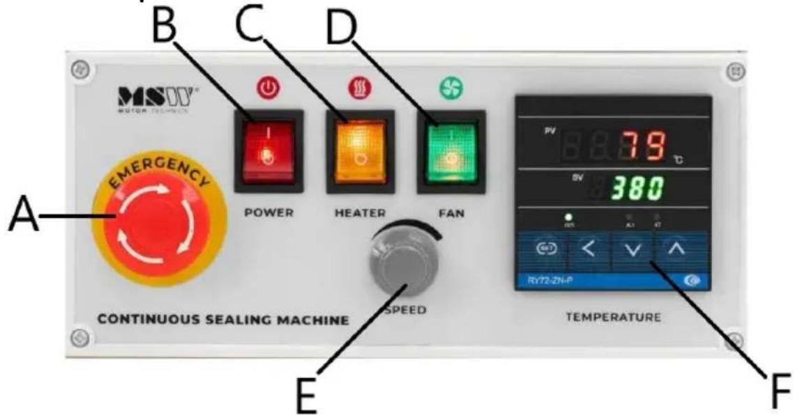
A Emergency button
B Power switch
C Heater switch
D Fan switch
E Speed adjustment
F
Hot sealing temperature adjustment
Preparations, adjustment and checks before use
- The machine is equipped with a three-pin plug with housing grounding. Ensure that proper grounding is in place during use to guarantee safe operation.
- When using the machine for the first time or after it has been inactive for an extended period, the electric heating element may have absorbed moisture. In this case, preheat the machine at a low temperature for several minutes before starting normal operations.
- Adjust the height and position of the conveying platform to meet the packaging requirements.
- Adjust the feeding inlet position according to the outline dimensions of the sealing line and the bag opening.
Adjustment of driven pulley adjusting block
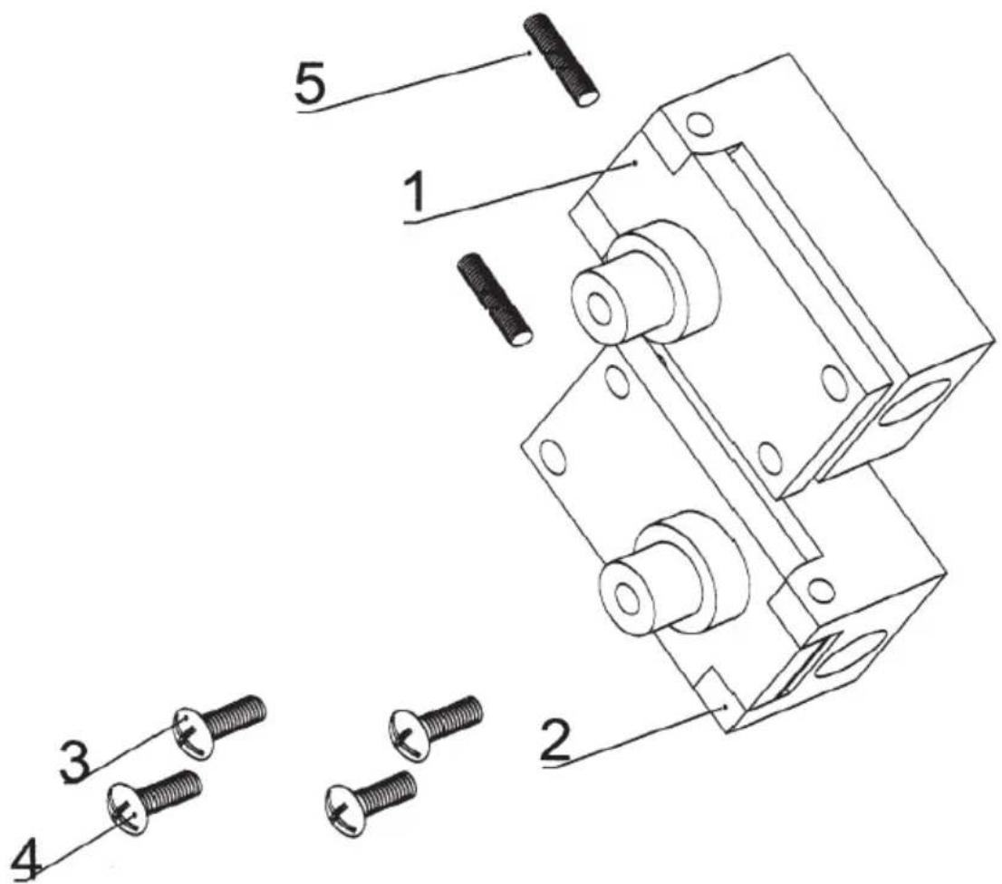
1 Driven wheel seat
2 Driven pully seat
3/4 Adjusting screw
5 Spring
Starting procedures:
-
Power On: Switch on the power and press the start switch. The indicator lamp will light up. Adjust the speed using the speed adjusting button. All driving parts will run synchronously.
-
Knurling Wheel Adjustment: Fine-tune the knurling wheel knob to adjust the pressure on the knurling wheel. Once the pressure is properly adjusted, fasten the limit screw.
-
Heating Switch: Switch on the heating, and the green light of the electronic temperature controller will turn on. Adjust the temperature of the controller based on the material and thickness of the packing bag. Start with low speed running during preheating.
-
Cooling Fan: Depending on the material and thickness of the plastic bag, decide if it's necessary to activate the fan for cooling.
-
Sealing Process: Adjust the feeding inlet and position the bag opening to be sealed. When the sealing tape grasps the bag, it will move forward automatically. Ensure not to push or block the bag to prevent improper sealing or faults.
-
Removing Obstructions: If there are dirty materials on the sealing tape or heating block, stop the machine and carefully remove them, as high temperatures may cause burns.
Stopping Procedures:
- Adjusting Knob: Before stopping the machine, first turn the adjusting knob back to zero.
- Fan: Turn on the fan to cool the system. The temperature pointer will start to drop.
- Sealing Tape Running: Keep the sealing tape running until the temperature falls below 100^ C.
6. Electric circuit diagram
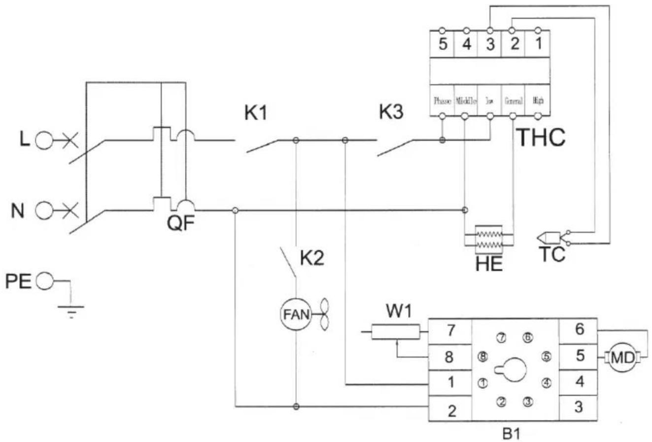
QF Circuit breaker
K1 Power switch
K2 Fan switch
K3 Thermal sealing switch
MD DC motor
FAN Axial flow fan
THC Temperature controller
TC Thermal couple
HE Heating tube
W1 Potentiometer
B1 High speed board
Troubleshooting
| Malfunction | Causes | Troubleshooting |
| The sealing tape deviates | The driving wheel shaft and driven wheel shaft are not parallel. | Adjust the two adjusting screws on the driven wheel seat to make sure there is no deviation. |
| The sealing tape is easily broken | 1. The sealing tape is too tight.2. The sealing tape deviates.3. The sealing tape has creases.4. The sealing face is stuck with film or other dirty things on the surface.5. The sealing tape is easily burnt. | 1. Adjust the vertical adjusting screw on the driven wheel seat to make sure tensioning of the sealing tape with proper tightness.2. See the above item.3. The sealing tape crease shall be removed.4. Remove the things sticking on the surface of the sealing tape.5. The interval between heating blocks is too small or the temperature is too high. |
| The knurling is not clear | 1. The knurling wheel wears out.2. The pressure spring of the knurling wheel seat is not tightened. | 1. Replace the knurling wheel.2. Adjust the pressure spring of the knurling wheel seat. |
| During the conveying, the sealing tape encounters resistance. | The interval between heating boards or cooling boards is too small or the friction is too high. | The interval between heating boards or cooling boards shall be proper, so that the interval between the two sealing tapes is about the thickness of a layer of packing bag to ensure sealing firmness and knurling clarity without prolonging the two ends of the sealing part too much. |
EN
| When the packing bag moves to the middle pressing wheel or knurling wheel, there is the occurrence of blocking or rolling into the wheel. | The pressure of the middle pressing wheel or knurling wheel is too high. | 1. The pressure of the middle pressing wheel or knurling wheel shall be proper, so that the interval between the two sealing tapes is about the thickness of a layer of packing bag to ensure sealing firmness and knurling clarity without prolonging the two ends of the sealing part too much.2. After the interval adjustment is finished, adjust the limit screw. |
| The conveyor belt deviates | The driving roller shaft and middle roller shaft are not parallel. | Adjust the two adjusting screws of the driven roller shaft (front shaft) on the conveying platform. |
| The conveyor belt is not synchronous with the sealing tape | The conveyor belt is not tightened. | 1. Properly tighten the chains of the driving roller shaft (front shaft) and middle shaft.2. Properly adjust the conveyor belt. |
PL

QF Jistič
K1 Vypínač napájení
QF Megszakító
4. Driftsbetingelser:
Procedurer for standsning:
1 Vetopyörän istuin
2 Vetävä istuin
3/4 Säätöruuvi
5 Jousi
QF Katkaisija
K1 Virtakytkin
QF Stroomonderbreker
4. Driftsbetingelser:
- Ikke bruk maskinen i etsende eller fuktige omgivelser.
5. Advarsel om endringer:
1 Drevet hjulsete
2 Drevet pully sete
3/4 Justeringsskrue
5 Fjær
Startprosedyrer:
QF Strømbryter
K1 Strømbryter
K2 Viftebryter
1 Driven hjulsäte
2 Drivsäte
3/4 Justerskruv
5 Fjäder
Startprocedurer:
QF Strömbrytare
K1 Strömbrytare
K2 Fläktomkopplare
QF Disjuntor
QF Istič
1 Varomo rato sédyné
2 Varoma traukiama sédyné
3/4 Reguliavimo varžtas
5 Pavasaris
1 Scaun pe roata condusa
2 Scaun cu role condus
3/4 Surub de reglare
RO
5 Primăvară
Proceduri de pornire:
QF Întrerupător
K1 Comutator de alimentare
K2 Comutator ventilator
For the disposal of the device please consider and act according to the national and local rules and regulations.
CONTACT
expondo Polska sp. z o.o. sp. k.