WB-270 - Wheel balancer MSW - Free user manual and instructions
Find the device manual for free WB-270 MSW in PDF.

| Brand | MSW |
| Model | WB-270 |
| Category | Wheel balancer |
| Type | Wheel balancer |
| Rated voltage | 230 V~ |
| Frequency | 50 Hz |
| Rated power | 270 W |
| Measurement time | 4 to 7 seconds |
| Measurement tolerance | ±5 g |
| Rotation speed | 200 rpm |
| Maximum wheel weight | 65 kg |
| Wheel diameter range | 10-24" / 254-610 mm |
| Wheel width range | 1.5-20" / 38-508 mm |
| Protection class | IP2X |
| Dimensions (L × W × H) | 880 × 1210 × 1400 mm |
| Weight | 65.5 kg |
| Balancing modes | Dynamic, static, ALU 1-3, special S |
| Special functions | Self-calibration, optimization, automatic start |
| Power supply | 230 V / 50 Hz, grounded plug |
| Maintenance and cleaning | Non-corrosive cleaner, brush and compressed air for vents, regular inspection |
| Safety | Wheel guard, on/off switch, automatic stop, warnings on rotating parts |
| Spare parts and repairability | Fuses, drive belt, sensors; repair by manufacturer only |
| General information | User manual in French, 323-page manual, email support |
Frequently Asked Questions - WB-270 MSW
User questions about WB-270 MSW
0 question about this device. Answer the ones you know or ask your own.
Ask a new question about this device
Download the instructions for your Wheel balancer in PDF format for free! Find your manual WB-270 - MSW and take your electronic device back in hand. On this page are published all the documents necessary for the use of your device. WB-270 by MSW.
USER MANUAL WB-270 MSW
natural_image
Pure mechanical diagram of a beam with supports, no text or symbols presentnatural_image
Pure mechanical component diagram without any text, numbers, or symbolsnatural_image
Pure mechanical diagram of a lever and fulcrum without any text, labels, or symbols• 2 ALU

• 3 ALU
natural_image
Pure mechanical diagram of a bent pipe or beam with two shaded sections (no text or symbols)This User Manual has been translated using machine translation. We have made every effort to ensure the translation is accurate, but please note that automated translations are not perfect and are not meant to replace human translators. The official version of the User Manual is in English. Any differences between the translated version and the original English are not legally binding. If you have any questions about the accuracy of the translation, please refer to the English version, which is the official reference. More language versions are available upon request via info@expondo.com.
Technical data
| Parameter description | Parameter value |
| Product name | Wheel balancer |
| Model | MSW-WB-270 |
| Rated voltage [V~]/ Frequency [Hz] | 230/50 |
| Rated power [W] | 270 |
| Measurement time [s] | 4÷7 |
| Measurement tolerance [g] | ±5 |
| Rotational speed [rpm] | 200 |
| Maximum wheel weight [kg] | 65 |
| Wheel diameter range | 10-24'' /254-610mm |
| Wheel width range | 1.5-20'' / 38-508mm |
| Protection class | IP2X |
| Dimensions [length * width * height; mm] | 880x1210x1400 |
| Weight [kg] | 65.5 |
1. General description
The user manual is designed to assist in the safe and trouble-free use of the device. The product is designed and manufactured in accordance with strict technical guidelines, using state-of-the-art technologies and components. Additionally, it is produced in compliance with the most stringent quality standards.
DO NOT USE THE DEVICE UNLESS YOU HAVE THOROUGHLY READ AND UNDERSTOOD THIS USER MANUAL.
To increase the product life of the device and to ensure trouble-free operation, use it in accordance with this user manual and regularly perform maintenance tasks. The technical data and specifications in this user manual are up to date. The manufacturer reserves the right to make changes associated with quality improvement. The device is designed to reduce noise emission risks to a minimum, taking into account technological progress and noise reduction opportunities.
Legend

The product satisfies the relevant safety standards.

Read instructions before use.

The product must be recycled.

WARNING! or CAUTION! or REMEMBER! Applicable to the given situation.
(general warning sign)

Wear protective goggles.

Wear protective gloves.

Wear foot protection.

ATTENTION! Electric shock warning!

ATTENTION! Rotating parts, entanglement hazard!

PLEASE NOTE! Drawings in this manual are for illustration purposes only and in some details may differ from the actual product.
2. Usage safety

ATTENTION! Read all safety warnings and all instructions. Failure to follow the warnings and instructions may result in electric shock, fire and/or serious injury or even death.
The terms "device" or "product" are used in the warnings and instructions to refer to
2.1. Electrical safety
a) The plug must fit the socket. Do not modify the plug in any way. Using original plugs and matching sockets reduces the risk of electric shock.
b) Avoid touching earthed elements such as pipes, heaters, boilers and refrigerators. There is an increased risk of electric shock if the earthed device is exposed to rain, comes into direct contact with a wet surface or is operating in a damp environment. Water getting into the device increases the risk of damage to the device and of electric shock.
c) Do not touch the device with wet or damp hands.
d) Use the cable only for its designated use. Never use it to carry the device or to pull the plug out of a socket. Keep the cable away from heat sources, oil, sharp edges or moving parts. Damaged or tangled cables increase the risk of electric shock.
e) If using the device in a damp environment cannot be avoided, a residual current device (RCD) should be applied. The use of an RCD reduces the risk of electric shock.
2.2. Safety in the workplace
a) Make sure the workplace is clean and well lit. A messy or poorly lit workplace may lead to accidents. Try to think ahead, observe what is going on and use common sense when working with the device.
b) Do not use the device in a potentially explosive environment, for example in the presence of flammable liquids, gases or dust. The device generates sparks which may ignite dust or fumes.
c) If you discover damage or irregular operation, immediately switch the device off and report it to a supervisor without delay.
d) If there are any doubts as to the correct operation of the device, contact the manufacturer's support service.
e) Only the manufacturer's service point may repair the device. Do not attempt any repairs independently!
f) In case of fire, use a powder or carbon dioxide (CO2) fire extinguisher (one intended for use on live electrical devices) to put it out.
g) Children or unauthorised persons are forbidden to enter a work station. (A distraction may result in loss of control over the device).
h) Use the device in a well-ventilated space.
i) Regularly inspect the condition of the safety labels. If the labels are illegible, they must be replaced.
j) Please keep this manual available for future reference. If this device is passed on to a third party, the manual must be passed on with it.

Remember! When using the device, protect children and other bystanders.
2.3. Personal safety
a) Do not use the device when tired, ill or under the influence of alcohol, narcotics or medication which can significantly impair the ability to operate the device.
b) The machine may be operated by physically fit persons who are able to handle the machine, are properly trained, who have reviewed this operating manual and have received training in occupational health and safety.
c) The machine is not designed to be handled by persons (including children) with limited mental and sensory functions or persons lacking relevant experience and/or knowledge unless they are supervised by a person responsible for their safety or they have received instruction on how to operate the machine.
d) When working with the device, use common sense and stay alert. Temporary loss of concentration while using the device may lead to serious injuries.
e) Use personal protective equipment as required for working with the device, specified in section 1 (Legend). The use of correct and approved personal protective equipment reduces the risk of injury.
f) To prevent the device from accidentally switching on, make sure the switch is on the OFF position before connecting to a power source.
g) Do not overestimate your abilities. When using the device, keep your balance and remain stable at all times. This will ensure better control over the device in unexpected situations.
h) Do not wear loose clothing or jewellery. Keep hair, clothes and gloves away from moving parts. Loose clothing, jewellery or long hair may get caught in moving parts.
i) Remove all adjusting tools or spanners before turning the device on. A tool or spanner left in the revolving part of the device may cause injury.
j) The device is not a toy. Children must be supervised to ensure that they do not play with the device.
k) The machine may be operated by only one person at a time.
I) The area around the machine should be free of oil stains, dangerous objects, etc. to eliminate hazardous situations for the user.
2.4. Safe device use
a) Do not overload the device. Use the appropriate tools for the given task. A correctly-selected device will perform the task for which it was designed better and in a safer manner.
b) Do not use the device if the ON/OFF switch does not function properly (does not switch the device on and off). Devices which cannot be switched on and off using the ON/OFF switch are hazardous, should not be operated and must be repaired.
c) Make sure the plug is disconnected from the socket before attempting any adjustments, accessory replacements or before putting the device aside. Such precautions will reduce the risk of accidentally activating the device.
d) When not in use, store in a safe place, away from children and people not familiar with the device who have not read the user manual. The device may pose a hazard in the hands of inexperienced users.
e) Keep the device in perfect technical condition. Before each use check for general damage and especially check for cracked parts or elements and for any other conditions which may impact the safe operation of the device. If damage is discovered, hand over the device for repair before use.
f) Keep the device out of the reach of children.
g) Device repair or maintenance should be carried out by qualified persons, only using original spare parts. This will ensure safe use.
h) To ensure the operational integrity of the device, do not remove factory-fitted guards and do not loosen any screws.
i) When transporting and handling the device between the warehouse and the destination, observe the occupational health and safety principles for manual transport operations which apply in the country where the device will be used.
j) Avoid situations where the device stops working during use due to excessive loading. This may result in overheating of the drive elements and damage to the device.
k) Do not touch articulated parts or accessories unless the device has been disconnected from the power source.
I) Do not move, adjust or rotate the device in the course of work.
m) Do not leave this appliance unattended while it is in use.
n) Clean the device regularly to prevent stubborn grime from accumulating.
o) The device is not a toy. Cleaning and maintenance may not be carried out by children without supervision by an adult person.
p) The machine may only be used by trained persons who understand its operation and safety rules.
q) Do not stand near the machine while it is running.
r) Make sure that the device is placed on a flat and
s) stable surface.
t) Make sure that the device does not slip under
u) influence of weight.
v) Do not exceed maximum permissible device load. This can result in device damage.
w) The wheel to be balanced must be free of dirt.
x) Do not lift the machine by holding the shaft.
y) Do not balance wheels with parameters that do not comply with the data provided in the technical data table.
z) Do not lift the cover while the wheel is in motion. The cover may only be lifted after the wheel has completely stopped.

ATTENTION! Despite the safe design of the device and its protective features, and despite the use of additional elements protecting the operator, there is still a slight risk of accident or injury when using the device. Stay alert and use common sense when using the device.
3. Use guidelines
The device is designed to measure wheel unbalance.
The user is liable for any damage resulting from unintended use of the device.
3.1. Device description
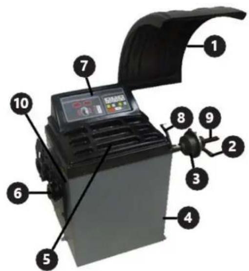
-
Wheel cover
-
Clamping nut
-
Centring cone
-
Housing
-
Containers
-
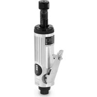
Hanger for additional equipment
-
Control panel
-
Distance measure
-
Shaft
-
SWITCH
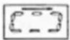
Description of the control panel
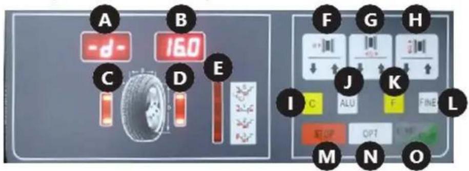
A. Display of inner tyre unbalance value
B. Display of outer tyre unbalance value
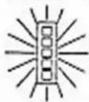
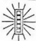
C. Indicator of inner tyre unbalance position
D. Indicator of outer tyre unbalance position
E. Indicator of the selected balancing mode
F. Distance entry button
G. Wheel width entry button
H. Wheel diameter entry button
- " /Gauto-calibration button
J. "ALU" button / balancing mode selection
(weights placing point)
K. Function button
L. "FUN"
M. "Sutton
N. " " QRTon
O. "START" button
3.2. Preparing for use
Transport
For transport, the machine should be properly secured on a pallet in its original packaging. Use a forklift or a pallet truck of suitable load capacity. The truck fork must be positioned centrally under the machine to prevent tipping during transport.
Appliance location
The temperature of environment must not be higher than 40^ C and the relative humidity should be less than 85%. Ensure good ventilation in the room in which the device is being used. Leave a space around the machine to allow free and safe use. Keep the device away from hot surfaces. Operate the device on an even, stable, clean, fire-proof and dry surface and out of the reach of children and persons with mental disabilities. Position the device such that you always have access to the power plug. The power cord connected to the appliance must be properly grounded and correspond to the technical details on the product label!
The machine should be connected by a person with the appropriate qualifications and knowledge. Attach the cover to the machine.
3.3. Device use
Machine operation
- Make sure that the On / Off switch is set to "Off".
- Connect the machine to a power source.
- Switch the machine on using the On / Off switch located on the side wall of the housing.
- Mount the wheel according to the instructions provided in the "Wheel mounting" section.
- Enter parameters according to the instructions provided in the "Parameter setting" section.
- Balance the tyre according to the instructions provided in the "Wheel balancing" section.
- After work is finished, turn the device off using the On / Off switch. For a longer break, disconnect the device from the power source.
NOTE: It is recommended to calibrate the device before the first use.
Wheel mounting
- The wheel should be placed with its central hole on the shaft. For a motorcycle wheel or a wheel with a special rim shape, use a distancer (not included) to increase the machine's measurement capability.
- Install the clamping nut and fix the wheel, taking care that it is set straight. A wheel placed askew will cause balance measurement errors.
Setting parameters
- Dimensions
After putting the wheel on and fixing it on the balancer, manually enter the values shown in the figure below:
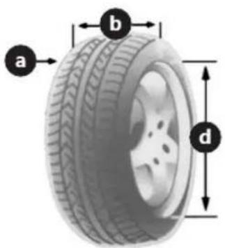
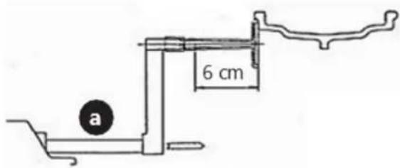
- "a" – distance between the inside of the wheel and the machine, measured using the built-in measure (8). This parameter is entered by pressing arrows on the control panel (F) button. The user can choose between two input units: mm and inches. To change the unit, press the "F (K) button and one of the (F) button arrows. To balance a motorcycle wheel or one with a non-standard rim, add the distance length to the measured "a" value. For example, in the case below enter the value "a + 6".
- "b" – width of the tyre, measured using the compass attached to the machine. The parameter is entered by pressing the arrows on the control panel (G) button. The user can choose between two input units: mm and inches. To change the unit, press the "F" (K) and one of the (G) arrows.
- "d" – wheel diameter, as provided by the manufacturer, which can be found on the tyre. This parameter is entered by pressing arrows on the control panel (H) button. The user can choose between two data entry units: mm and inches. To change the unit, press "F" (K) and one of the (H) arrows.
The symbol of the value entered (a, b or d) will be shown on the (A) display, while the current numerical value will be shown on the (B) display.
- Balancing modes
The user can choose between 6 balancing modes which differ in the way the balancing weights are distributed. The modes are chosen using the "F (K) and "A(U)buttons.
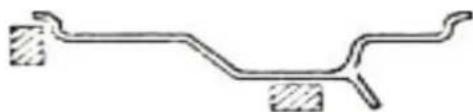
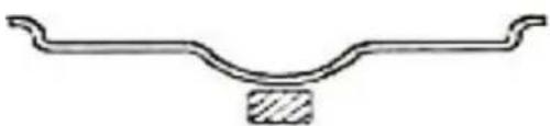
With the "F" (K) button, the user can select between the dynamic and static modes described below:
• Dynamic mode – designed for balancing wheels with steel or light alloy rims.
natural_image
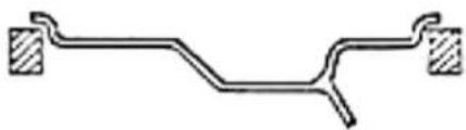
Pure mechanical diagram of a beam with supports, no text or symbols present- Static mode – designed for balancing motorcycle wheels and car wheels with non-standard rims, where it is impossible to attach two weights.
natural_image
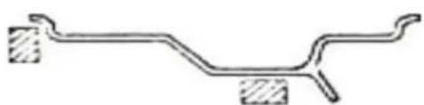
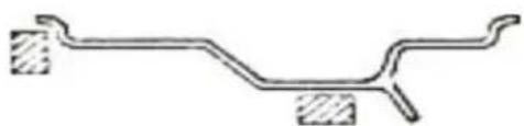
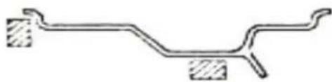
Pure mechanical component diagram without any text, numbers, or symbolsWith the "Al(U) button, the user can select between 1 to ABU modes and the special "" mode. S An LED lights up on the (E) indicator next to the selected mode. The AbModes are used for balancing light alloy wheels. The drawings below show the arrangement of weights on the rim for given modes and a detailed description of the special "S function.
• 1 ALU
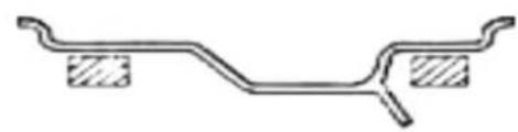
natural_image
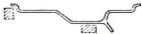
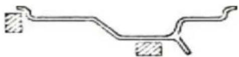
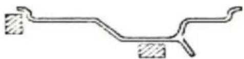
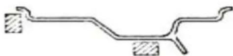
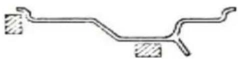
Pure mechanical diagram of a bent pipe or beam with two shaded rectangular sections (no text or symbols)• 2 ALU

• 3 ALU
natural_image
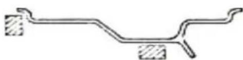
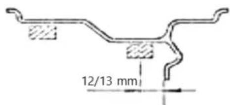
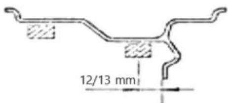
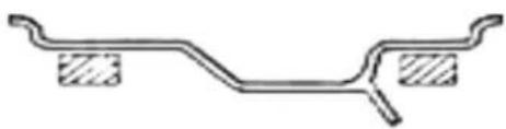
Pure mechanical diagram of a bent pipe or beam with two shaded sections (no text or symbols)- The Special "S" mode is intended for balancing aluminium wheels with non-standard shapes, where the ALU2 mode will not guarantee the proper balancing accuracy. For this mode special parameters must be entered.
First, use the "ALU" (J) button to select the special "S" mode, then proceed to enter the dimensions shown in the drawing below.
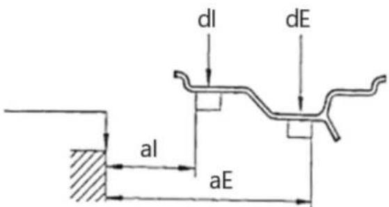
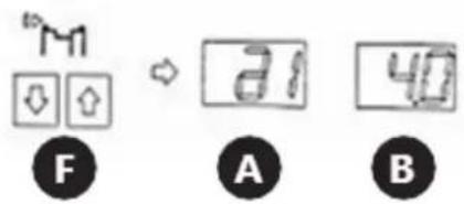
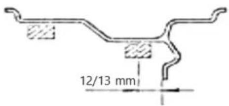
Below is the sequence and manner of entering the above dimensions (the button designations used under the drawings are those described in item 3.1):
- al – This parameter is entered by pressing the (F) arrows on the control panel.
- aE – This parameter is entered by pressing the (G) arrows on the control panel.
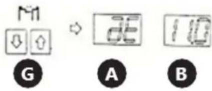
- dl—This parameter is entered by pressing the (H) arrows on the control panel.
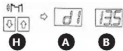
- dE – This parameter is entered by holding the "ALU" (J) button and pressing the (H) arrows on the control panel. If the user is in the "dl" parameter setting mode and holds down the "ALU" (J) button, the device will automatically set the value of dE0.8. dl
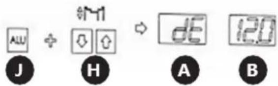
The system automatically calculates the distance between the gravity centres of the weights, assuming that their width is approx. 14 mm.
- The machine can be set to automatically start the balancing process after the wheel guard is closed. To activate this function, press and hold the "F" (K) and "STOP" (M) buttons on the control panel at the same time. This setting is erased after the machine is switched off and on again.
Wheel balancing
- Close the wheel guard. Press the "START" (O) button unless the automatic start-up of the machine has been set.
- The wheel gain speed for a few seconds. After the device has measured the unbalance, the wheel will stop and the (A) and (B) displays will show the weights needed to balance the tyre.
- Lift the wheel cover, then place the appropriate weights on the rim as follows: Turn the wheel slowly with your hand until one of the indicators, (C) or (D), is fully lit. If the (C) indicator comes on, place the weight on the inner side of the wheel in the 12 o'clock position. If the (D) indicator comes on, place the appropriate weight on the outer side of the wheel, also in the 12 o'clock position.

- Briefly pressing the "C" button will display a sequence of pre-set parameters.
- If incorrect wheel parameters are entered, it is possible to recalculate the indicated values without performing another measurement. To do this, press the "©" button longer. The new unbalance values will appear on the (A) and (B) displays.
- By default, when the device has calculated an unbalance of less than 5g, the (A) or (B) display will show the "0" value. The user can display the <5g value by pressing the " " (L) button.
Optimization function
The optimization function enables you to reduce the weight added to the wheel in order to balance it. This is recommended for indications above 30g in static balancing. To start the optimization function, press the "OPT(N) button. You can exit this function by pressing the "" (M) button.
To use a function, do the following:
- Press the " " (N) button. The displays will show:
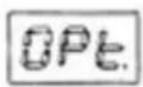

- Press the "START" (O) button. The device will perform one measurement cycle after which the displays will show:
- Mark reference points with chalk on the tyre and rim, then remove the wheel from the balancer and use appropriate tools to turn the tyre 180° on the rim. Re-install the wheel in the balancer so that the reference point marked on the rim is in the same place as before.
- Press the "START" (O) button again, the device will carry out the measuring cycle.
- The tyre unbalance value will appear on the (A) display while the (B) display will show in % to what value the balance can be optimised by turning the tyre on the rim.
-
Turn the wheel by hand until one of the (C) or (D) indicators lights up, make a mark with chalk on the tyre in the 12 o'clock position. Continue to turn the wheel by hand until the second indicator lights up, then make a mark with chalk on the rim in the 12 o'clock position. Remove the wheel from the balancer and use appropriate tools to turn the tyre 180° on the rim so that the chalk marks overlap.
-
Press the "STOP" (M) button to exit the optimisation function.
Self-calibration
The device has an automatic calibration function. In order to use it, mount a medium-sized wheel on the balancer, even if the tyre is unbalanced, then follow the instructions below.
-
Enter the wheel parameters in accordance with the instructions in the "Dimensions" part of "Setting parameters" section. NOTE: Incorrect entry of data will result in errors in the calibration of the device, and the unbalance measurement will be wrong.
-
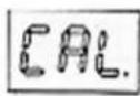
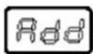
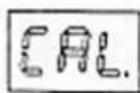
Keep pressing the "F" (K) and "C" (I) buttons until the (C) and (D) indicators stop flashing and "CAL" appears on the (A) and (B) displays.
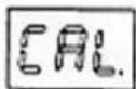
- Carry out an initial measurement. Press the "START" (O) button. The (D) indicator will light up and the following texts will appear on the displays:


-
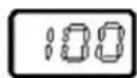
Add a load of 100g from the device side and start the calibration measurement.
-
After completing the measurement, remove the load from the inside of the wheel and put it on the other side (outside). Carry out a calibration measurement.
-
Calibration process complete.
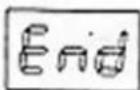
- Remove the 100g weight from the wheel.
The device remembers the calibration settings even after the power supply is disconnected. Calibration should always be performed when there is a suspicion that the machine balances tyres incorrectly.
Removing the wheel
-
Turn the clamping nut counterclockwise several times.
-
Release the nut lock and take the nut off the machine shaft.
-
Remove the wheel.
Hazards in the course of using the device
The hazards that can occur during use of the machine are mechanical hazards. The mechanical hazard occurs in situations in which injuries can result from mechanical impact of various elements, e.g. machine parts, tools, etc. on people. The basic mechanical hazards include squeezing, crushing, cutting, pulling in or
catching; impact; puncture; abrasion; as well as slipping and stumbling. These hazards can occur both during normal machine operation and as a result of irregularities in machine operation. These irregularities might result in machine failure. The mechanical hazards can result from: moving machines, transported loads, moving elements, sharp/ rough elements, dropping elements/loads, slippery uneven surfaces, limited space, location of the work station in relation to the ground.
4. Use guidelines Inspections and periodic control
Before being used, the new or repaired machine must be checked by qualified technical personnel who have knowledge and experience within the scope of operation and maintenance of this type of machine. The machine must be checked regularly by means of visual control of the machine's condition, before, during and after use. The check must be performed by the machine's operators. Any irregularities in machine operation as well as any damage must be reported to the proper technical personnel. Do not use the machine if damage or any irregularities in its operation were found.
NOTE: Disconnect the machine from the power supply before each inspection.
Preliminary inspection
Before first use. All new or repaired machines must be checked by a qualified and competent person to ensure the machine meets the requirements of this operating manual.
Daily check:
- Check the operation of the switch.Off
- Check the condition of all moving parts of the machine.
Periodic inspection
- Adjusting the tension of the drive belt:
Slightly loosen the nuts holding the motor. Gently move the motor to obtain the correct tension of the drive belt. Bolt the motor and make sure that the belt does not slip and that it does not come into contact with the motor housing.
- Fuse replacement
Fuses are located on the power board. Unscrew the side of the machine where the hangers are located, then replace the damaged fuses with new ones.
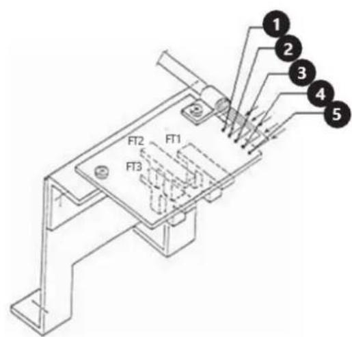
- Position sensor check
Make sure that none of the photocells rub against any of the machine components.
Using the voltmeter, measure the following voltage values:
a) Between wires "4" and "5" (it should be 5V)
b) Between wires "4" and "2" (it should be 4.5 to 4.8 V if the RESET button is inside the photocell FT2 and 0V if it is outside).
c) Between wires "4" and "1" (it should be 4.5 to 4.8V if the RESET button is outside the FT2 photocell)
d) Between wires "4" and "3" (it should be in the 0 - 4.8V range when the machine shaft is rotated slowly)
NOTE: When the sensor needs to be replaced, it is recommended to unscrew the printed circuit board (two screws) instead of unscrewing the entire bracket.
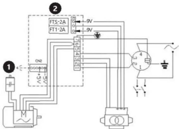
5. Wiring diagram
-
Computer board
-
Power board
6. Cleaning and maintenance
a) Unplug the mains plug before each cleaning, adjustment or replacement of accessories, or if the device is not being used.
b) Use only non-corrosive cleaners to clean the surface.
c) After cleaning the device, all parts should be dried completely before using it again.
d) Store the unit in a dry, cool place, free from moisture and direct exposure to sunlight.
e) Never spray the device with water.
f) Clean the vents with a brush and compressed air.
g) The device must be regularly inspected to check its
h) technical efficiency and spot any damage.
i) Don't clean the machine with compressed air.
7. Troubleshooting
| Error code | Description |
| Err1 | No input signals. Possible causes: faulty or improperly connected position sensor, damaged or improperly connected pressure sensor, the motor does not work. |
| Err2 | The wheel rotates at a speed of less than 60 rpm. |
| Err3 | The wheel imbalance is too great. It exceeds the measuring range of the device. |
| Err4 | The motor rotates in the opposite direction. Incorrect connection of the position sensor. |
| Err5 | The measurement is started before the wheel guard is closed. |
| Err7 | Error in the memory of the auto-calibration value. |
| Err8 | No reference weight added during auto- calibration. Pressure sensor damaged or improperly connected. |

natural_image
Pure mechanical diagram of a bent pipe or beam with two side supports (no text or symbols)natural_image
Pure mechanical component diagram without any text, numbers, or symbolsnatural_image
Pure mechanical diagram of a lever or fulcrum with two supports, no text or symbols present• 2 ALU

• 3 ALU
natural_image
Pure mechanical diagram of a bent pipe or beam with two shaded sections (no text or symbols)natural_image
Pure mechanical diagram of a beam with supports, no text or symbols presentnatural_image
Pure mechanical component diagram without any text, numbers, or symbolsnatural_image
Pure mechanical diagram of a bent pipe or beam with two side supports (no text or symbols)• 2 ALU
• 3 ALU

natural_image
Pure mechanical diagram of a bent pipe or beam with two shaded sections, no text or symbols present.natural_image
Pure mechanical diagram of a beam with supports (no text or symbols)natural_image
Pure mechanical component diagram without any text, numbers, or symbolsnatural_image
Pure mechanical component diagram without any text, numbers, or symbols• 2 ALU

• 3 ALU
natural_image
Pure mechanical diagram showing a bent pipe or beam with two hatched sections at both ends (no text or symbols)natural_image
Pure mechanical diagram of a bent pipe or beam with two side supports (no text or symbols)natural_image
Pure mechanical component diagram without any text, numbers, or symbolsnatural_image
Pure mechanical diagram showing a bent pipe or beam with two hatched sections at both ends (no text or symbols)natural_image
Pure mechanical diagram of a beam with supports and cross-hatching (no text or symbols)natural_image
Pure mechanical component diagram without any text, numbers, or symbolsnatural_image
Pure mechanical diagram of a lever or support structure without any text, numbers, or symbols• 2 ALU

• 3 ALU

natural_image
Pure mechanical diagram of a bent pipe or beam with two shaded sections at both ends (no text or symbols)natural_image
Pure mechanical diagram of a beam with supports, no text or symbols presentnatural_image
Pure mechanical component diagram without any text, numbers, or symbolsnatural_image
Pure mechanical diagram showing a bent pipe or beam with two rectangular supports at both ends (no text or symbols)• 2 ALU

• 3 ALU
natural_image
Pure mechanical diagram of a bent pipe or channel with two shaded sections (no text or symbols)natural_image
Pure mechanical diagram of a beam with supports, no text or symbols presentnatural_image
Pure mechanical component diagram without any text, numbers, or symbolsnatural_image
Pure mechanical diagram of a bent pipe or beam with two shaded rectangular sections (no text or symbols)• 2 ALU
• 3 ALU

natural_image
Pure mechanical diagram of a lever or fulcrum with two hatched sections at both ends (no text or symbols)natural_image
Pure mechanical diagram of a beam with supports, no text or symbols presentnatural_image
Pure mechanical component diagram without any text, numbers, or symbolsnatural_image
Pure mechanical diagram of a lever or support structure without any text, numbers, or symbols• 2 ALU

• 3 ALU

natural_image
Pure mechanical diagram of a lever or support structure without any text, numbers, or symbolsnatural_image
Pure mechanical diagram of a beam with supports, no text or symbols presentnatural_image
Pure mechanical component diagram without any text, numbers, or symbolsnatural_image
Pure mechanical diagram of a lever and fulcrum without any text, labels, or symbols• 2 ALU
• 3 ALU

natural_image
Pure mechanical diagram of a bent pipe or beam with two hatched sections at both ends (no text or symbols)-
Hjuldeksel
-
Klemmutter
-
Sentrerende kjegle
-
Bolig
-
Containere
-
Henger for tilleggsutstyr
-
Styrepanel
-
Avstandsmål
-
Aksel
-
ON/OFF
natural_image
Pure mechanical diagram of a lever or support structure without any text, numbers, or symbolsnatural_image
Pure mechanical diagram of a beam with supports and cross-sections, no text or symbols presentnatural_image
Pure mechanical component diagram without any text, numbers, or symbolsnatural_image
Pure mechanical diagram of a bent pipe or beam with two shaded rectangular sections (no text or symbols)• 2 ALU

• 3 ALU

natural_image
Pure mechanical diagram of a lever or fulcrum with two hatched sections at both ends (no text or symbols)natural_image
Pure mechanical diagram of a beam with supports (no text or symbols)natural_image
Pure mechanical component diagram without any text, numbers, or symbolsnatural_image
Pure mechanical diagram of a bent pipe or beam with two shaded rectangular sections (no text or symbols)• 2 ALU

• 3 ALU
natural_image
Pure mechanical diagram of a bent pipe or beam with two side supports (no text or symbols)natural_image
Pure mechanical diagram of a beam with supports, no text or symbols presentnatural_image
Pure mechanical component diagram without any text, numbers, or symbolsnatural_image
Pure mechanical diagram of a bent pipe or conduit with two shaded rectangular components (no text or symbols)• 2 ALU

• 3 ALU
natural_image
Pure mechanical diagram of a bent pipe or beam with two side supports (no text or symbols)natural_image
Pure mechanical diagram of a beam with supports, no text or symbols presentnatural_image
Pure mechanical component diagram without any text, numbers, or symbolsnatural_image
Pure mechanical component diagram without any text, numbers, or symbols• 2 ALU

• 3 ALU
natural_image
Pure mechanical diagram of a lever or fulcrum with two hatched sections at both ends (no text or symbols)natural_image
Pure mechanical diagram of a bent pipe or beam with two side supports (no text or symbols)natural_image
Pure mechanical component diagram without any text, numbers, or symbolsnatural_image
Pure mechanical diagram of a lever or fulcrum with two supports and a central shaft (no text or symbols)• 2 ALU

• 3 ALU

natural_image
Pure mechanical diagram of a bent pipe or beam with two shaded sections (no text or symbols)-
Poklopac kotača
-
Stezna matica
-
Konus za centriranje
-
Kućište
-
Kontejneri
-
Vješalica za dodatnu opremu
-
Upravljačka ploča
-
Mjera udaljenosti
-
Vratilo
10. prelodac
natural_image
Pure mechanical diagram of a beam with supports, no text or symbols presentnatural_image
Pure mechanical component diagram without any text, numbers, or symbolsTipkom "" (ALUJ) korisnik može birati između ALU1 do ALU3 načina rada i posebnog S načina rada """. Na indikatoru (E) pored odabranog načina rada svijetli LED. Načini ALU se koriste za balansiranje kotača od lake legure. Crteži u nastavku prikazuju raspored utega na rubu za dane načine rada i detaljan opis posebne S funkcije """.
• 1 ALU
natural_image
Pure mechanical diagram of a lever and shaft without any text, numbers, or symbols• 2 ALU

• 3
- Poseban način "" namijenjen je za balansiranje aluminijskih kotača nestandardnih oblika, pri čemu način 2 neće jamčiti odgovarajuću točnost balansiranja. Za ovaj način moraju se unijeti posebni parametri.
Najprije upotrijebite gumb "" ( J) za odabir posebnog "" načina rada, zatim nastavite s unosom dimenzija prikazanih na donjem crtežu.
Dolje je redoslijed i način unosa gornjih dimenzija (oznake gumba korištene ispod crteža su one opisane u točki 3.1):
- U ovaj parametar ulazi se pritiskom na strelice (F) na upravljačkoj ploči.
A. Vidinès padangos disbalanso vertés rodymas
natural_image
Pure mechanical diagram of a beam with supports, no text or symbols presentnatural_image
Pure mechanical component diagram without any text, numbers, or symbolsnatural_image
Pure mechanical diagram of a lever or fulcrum with two supports, no text or symbols present• 2 ALU

• 3
natural_image
Pure mechanical diagram of a beam with supports, no text or symbols presentnatural_image
Pure mechanical component diagram without any text, numbers, or symbolsnatural_image
Pure mechanical diagram of a bent pipe or beam with two shaded rectangular sections (no text or symbols)• 2 ALU

• 3 ALU
natural_image
Pure mechanical diagram of a bent pipe or beam with two hatched sections at both ends (no text or symbols)natural_image
Pure mechanical diagram of a beam with supports, no text or symbols presentnatural_image
Pure mechanical component diagram without any text, numbers, or symbolsnatural_image
Pure mechanical diagram of a lever or fulcrum with two supports, no text or symbols present• 2 ALU

• 3 ALU
natural_image
Pure mechanical diagram of a bent pipe or channel with two shaded sections (no text or symbols)For the disposal of the device please consider and act according to the national and local rules and regulations.
CONTACT
expondo Polska sp. z o.o. sp. k.