FR 30 E 45 TOUCH - Dryer Ghibli & Wirbel - Free user manual and instructions
Find the device manual for free FR 30 E 45 TOUCH Ghibli & Wirbel in PDF.

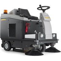
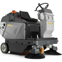
| Product type | Self-propelled floor scrubber (walk-behind) |
| Brand | Ghibli & Wirbel |
| Model | FR 30 E 45 TOUCH |
| Power supply | 230 V / 115 V (depending on version) |
| Installed power | 850 W |
| Cleaning width | 430 mm |
| Suction width | 650 mm |
| Solution tank capacity | 30 liters |
| Recovery tank capacity | 33 liters |
| Dimensions (L x W x H) | 1210 x 560 x 1020 mm |
| Empty weight | 70.5 kg |
| Operating weight | 100.5 kg |
| Main functions | Washing, scrubbing, drying (independent or combined cycles) |
| Maintenance and cleaning | Draining and cleaning tanks, cleaning filters, replacing brushes and squeegees |
| Safety | Maximum recovery water level alarm, residual current device recommended |
| Spare parts and repairability | Brush, squeegee rubber, fuses, filters available |
| Included accessories | Brush, squeegee, filling hose, filter, fuses, anti-pull hook |
| General information | User and maintenance manual provided |
Frequently Asked Questions - FR 30 E 45 TOUCH Ghibli & Wirbel
User questions about FR 30 E 45 TOUCH Ghibli & Wirbel
0 question about this device. Answer the ones you know or ask your own.
Ask a new question about this device
Download the instructions for your Dryer in PDF format for free! Find your manual FR 30 E 45 TOUCH - Ghibli & Wirbel and take your electronic device back in hand. On this page are published all the documents necessary for the use of your device. FR 30 E 45 TOUCH by Ghibli & Wirbel.
USER MANUAL FR 30 E 45 TOUCH Ghibli & Wirbel
natural_image
Line drawing of a cleaning or cleaning service robot with wheels and control panel (no text or symbols)FR30
E45 TOUCH

CE
49 0219 00
ed. 05/2022
IT Uso e Manutenzione
EN Use and Maintenance
FR Utilisation et Entretien
DE Gebrauch und wartung
ES Uso y Mantenimiento
PT Uso e manutenção
NL Gebruik en Onderhoud
CS Použití a Údržba
RU Эксплуатация и обслуживание
PL Obsługa i Konserwacja
AR الاستخدام والصيانة
NO Bruk og vedlikehold
DK Brug og vedligeholdelse
SV Användning och underhåll
SK Použitie a údržba
TR Kullanım ve Bakım
HU Használat és karbantartás
RO Folosire și întreținere
EL Χρήση και Συντήρηση
HR Upotreba i održavanje
SR Употреба и одржавање
BG Инструкции за използване и поддръжка
ET Kasutamine ja hooldus
FI Käyttö ja huolto
LV Ekspluatācija un uzturēšana
LT Eksploatavimas ir priežiūra
SL Delovanje in vzdrževanje
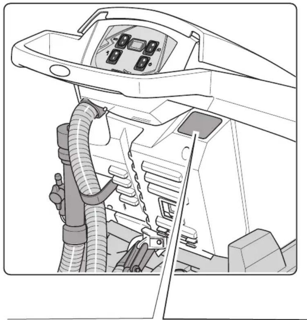
natural_image
Technical line drawing of a vehicle's internal components, showing hoses and control panel (no text or symbols)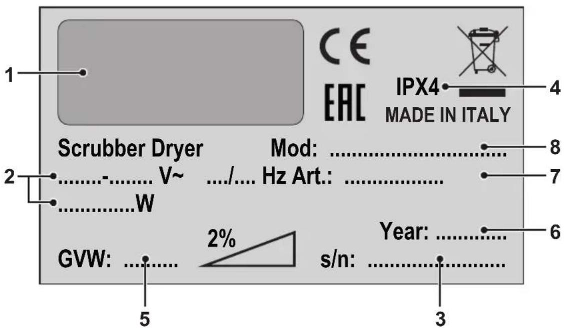
| 12345678 | ||||||||
| IT | Produttore | Caratteristiche elettriche | N° Matricola | Grado di protezione | Peso in ordine di marcia | Anno di costruzione | Codice articolo | Modello |
| EN | Manufacturer | Electrical characteristics | Serial N° | Degree of protection | Weight in running order | Year of manufacture | Item code | Model |
| FR | Producteur | Caractéristiques électriques | N° Matricule | Degré de protection | Poids en ordre de marche | Année de construction | Référence de l'article | Modèle |
| DE | Hersteller | Elektrische Eigenschaften | Matrikelnr. | Schutzgrad | Gewicht bei Betrieb | Baujahr | Artikelnummer | Modell |
| ES | Fabricante | Características eléctricas | N° Matrícula | Grado de protección | Peso en orden de marcha | Año de fabricación | Código del artículo | Modelo |
| PT | Produtor | Características eléctricas | Número de série | Grau de protecção | Peso em ordem de marcha | Ano de construção | Código do artigo | Modelo |
| NL | Producent | Elektrische eigenschappen | Serienummer | Beschermingsgraad | Gewicht in rijklare toestand | Bouwjaar | Artikelcode | Model |
| NO | Produsent | Elektriske egenskaper | Matrikkelnr. | Grad av beskyttelse | Vekt i kjøreklar stand | Byggeår | Artikkelnummer | Modell |
| DK | Fabrikant | El-specifikationer | Matrikelnummer | Tæthedsgrad | Vægt i køreklar stand | Byggeår | Artikelkode | Model |
| SV | Tillverkare | Elektriska egenskaper | Serienummer | Grad av skydd | Vikt i körklart skick | Byggnadsår | Artikelnummer | Modell |
| PL | Producent | Właściwości elektryczne | Nr. Fabryczny | Stopień ochrony | Cieżar w stanie pracy | Rok produkcji | Kod produktu | Model |
| CS | Výrobce | Elektrické údaje | Výrobní č. | Úroveň ochrany | Hmotnost v provozním stavu | Rok výroby | Kód položky | Model |
| SK | Výrobca | Elektrické vlastnosti | Výrobné č. | Úroveň ochrany | Hmotnost v provozním stavu | Rok výroby | Kód položky | Model |
| TR | Üretici | Elektriksel Özellikler | Seri No | Koruma sınıfı | Çalışma hali ağırlık | Yapım yılı | Ürün Kodu | Model |
| HU | Gyártó | Elektromos sajátosságok | Törzskönyvi szám | Védelmi szint | Súly működés közben | Gyártási év | Cikkszám | Modell |
| RO | Producâtor | Caracteristici electrice | Nr. Matricol | Grad de protectie | Greutate în stare de functionare | Anul de constructie | Cod articol | Model |
| EL | Κατασκευαστής | Ηλεκτρικά χροακτηριστικά | Αρ. Мητρώου | Βαθμός προστασίας | Βάρος στην λειτουργία | Έτος κατασκευής | Κώδικας του είδους | Μοντέλο |
| RU | Изготовитель | Электрические характеристики | Заводской No | Степень защиты | Эксплуатационный вес | Год выпуска | Код изделия | Модель |
| HR | Proizvođač | Električna svojstva | Registracijski br. | Stepen zaštičenosti | Težina u momentu rada | Godina proizvodnje | Kod artikla | Model |
| SR | Произвођач | Електричне характеристике | Бр ° Производа | Степен заштићености | Тежина у моменту рада | Година производње | Шифровање производа | Модел |
| BG | Производител | Електрически характеристики | Сериен номер | Степен на защита | Работно терло | Година на производство | Код на продукта | Модел |
| ET | Tootja | Elektrilised omadused | Seerianumber | Määral kaitset | Kaal töökorras | Ehitamise aasta | Koodeksi artikkel | Mudel |
| FI | Valmistaja | Sähköiset ominaisuudet | Sarjanumero | Kotelointiluokka | Paino ajokunnossa | Rakennusvuosi | Tuotenumero | Mallil |
| LV | Ražotājs | Elektriskie raksturlielumir | Sērijas numurs | Aizsardzības pakāpe | Svars braukšanas kārtībā | Gads būvniecībā | Vienības numurs | Modelis |
| LT | Gamintojas | Elektrinês charakteristikos | Eilės numeris | Apsaugos laipsnis | Eksploatacinė masė | Statybos metai | Prekės numeris | Modelis |
| SL | Proizvajalec | Električne značilnosti | Serijska številka | Stopnja zaščite | Teža pripravljenega za vožnjo | Leto izgradnje | Zaporedna številka | Model |
| AR | الصانع | المواصفات الكهربائية | الرقم التسلىلى | درجة المحاسبة | الوزن في وضعية التشغيل | سنة الصنج | رمز المنتج | الطراز |
EN English ...... ENGLISH -1
(Translation of original instructions)
FR Français ...... FRANÇAIS -1
Thank you for choosing one of our cleaning products.
The floor scrubber dryer that you have purchased has been designed to satisfy the user in terms of ease of use and reliability over time.
We are aware that in order for a good product to stay that way, over time, it requires continuous updates aimed at meeting the expectations of those who use it on a daily basis. For this reason, we hope that you will not only be a satisfied customer but also a partner who does not hesitate to give us your opinions and ideas originating from your personal day-to-day experience.
Indice
Technical data......EN-3
1.1 Introduction......EN-5
2.1 Getting to know the machine......EN-5
3.1 Unpacking......EN-5
3.1.a - Standard machine equipment......EN-5
4.1 Assembling the components......EN-5
4.1.a - Wiper assembly ......EN-5
4.1.b - Brush assembly ......EN-5
5.1 Control panel......EN-6
6.1 Filling the tank......EN-6
7.1 Operation......EN-6
7.1.a - Checks before use......EN-6
7.1.b - Electrical connection ......EN-6
7.1.c - Preparing the machine and choosing the cycle ......EN-7
7.1.d - Using the machine......EN-7
7.1.e - End of use and switching off......EN-7
7.1.f - Maximum recovery tank water level alarm ......EN-8
8.1 Draining the recovery water ......EN-8
9.1 Maintenance and cleaning ......EN-8
9.1.a - Emptying and cleaning the clean water tank ......EN-8
9.1.b - Cleaning the recovery water tank......EN-9
9.1.c - Cleaning the squeegee ......EN-9
9.1.d - Cleaning the clean water filter ......EN-9
9.1.e - Replacing the brush ......EN-9
9.1.f - Replacing the squeegee rubber blades......EN-10
9.1.g - Cleaning the recovery water tank......EN-10
9.1.h - Replacing the fuses ......EN-10
9.1.i - Wiper adjustment......EN-10
Troubleshooting......EN-12
10.1 Warranty ......EN-13
Wiring diagram....EN-14
FR 30 - FR 45 TOUCH 115 VAC......EN-14
FR 30 - FR 45 TOUCH 230 VAC ......EN-15
Technical data
| Type of use Operator on ground | |
| Characteristics | |
| Power supply voltage See technical data plate | |
| Installed load 850 W | |
| Forward movement Manual | |
| Washing width * 430 mm | |
| Drying width 650 mm | |
| Brushes / Pad | |
| Diameter / Number 430mm/17"x1 | |
| Motor power / number 450 Wx1 | |
| Motor speed 140 | rpm |
| Specific pressure 33 gr/cm | 2 |
| Aspiration | |
| Motor power 400 W | |
| Negative pressure 1189 mmH | 2O |
| Air flow rate 28 l / sec | |
| Noise level 63 dB | |
| Tank | |
| Recirculation No | |
| Solution capacity 30 l | |
| Recovery capacity 33 l | |
| Dimensions (lxwxh) without wiper | 1210 x 560 x 1020 mm |
| Vibrations ISO 5349 m/sec ^2 | < 2,5 |
| Weight | |
| Empty weight 70,5 Kg | |
| Weight in running order GVW 100,50 Kg | |
| Accessories | |
| 0.9 ø PPL brush 40.0002.00 | |
| Brush spray guard 24.0237.00 | |
| Front rubber wiper element 39.0129.00 | |
| Rear rubber wiper element 39.0130.00 | |
| Optional accessories | |
| 0.7 ø PPL strong brush 40.0102.00 | |
| 1.2 ø grit 80 tynex brush 40.0202.00 | |
| Drive mechanism 40.1007.00 | |
| Front anti-oil rubber wiper element 39.0131.00 | |
| Rear anti-oil rubber wiper element 39.0132.00 | |
1.1 INTRODUCTION

DANGER:
Before using the machine, carefully read the attached "SAFETY WARNINGS FOR THE FLOOR SCRUBBER DRYER" manual.
2.1 GETTING TO KNOW THE MACHINE (Fig. 1)
1) Guide handle.
2) Control console.
3) Squeegee activation lever.
4) Water supply tap.
5) Solution tank.
6) Tank cover.
7) Clean water filling opening.
8) Wheels.
9) Brush rotation flange.
10) Brush.
11) Squeegee.
12) Recovery water drain hose.
13) Squeegee water aspiration hose.
14) Recovery water tank.
15) Clean water drain/level tube.
16) Electric connection plug.
17) Clean water filter.
18) Brush up/down pedal.
19) Brush rotation activation button.
20) Touch sensor for starting traction and brush rotation.
3.1 UNPACKING (Figg. 1-2)
Once the packaging has been removed as shown in the instructions on the packaging itself, check that the machine and all the components supplied are intact.
If any evident damage is found, contact the area agent and the carrier within 3 days of receipt.
- Remove the bag (21) containing the accessories.
- Cut the strap (22).
- Remove the wooden blocks (23 and 24).
-
Lift the brush flange (9) by pressing down on the pedal (19) (see relative paragraph).
-
Lift the wiper support (25) by lifting the handle (3 Fig. 1) (see relative paragraph).
- Position a chute and unload the machine from the bench.
3.1.a - Standard machine equipment (Fig. 3)
The accessories supplied are as follows:
10) Brush/brushes.
11) Wiper.
26) Water filling hose.
27) Machine use and maintenance manual.
28) Anti-tear hook.
29)Fuses.
30) Filter for clean water tank opening.
4.1 ASSEMBLING THE COMPONENTS
4.1.a - Wiper assembly (Fig. 4)
- Loosen the two handwheels (31) located on the wiper (11).
- Assemble the wiper (11) on the support (25), tightening the two handwheels (31).
- Connect the tube (13) to the wiper connector (32).

N.B.:
Perform the previous operations with the wiper support lowered.
4.1.b - Brush assembly (Fig. 5)

HAZARD:
Operation to be performed by two people!
- Lift the brush rotation flange (9) slightly and remove the polystyrene protection (33).
- Assemble the brush as described in the paragraph "replacing the brush".
5.1 CONTROL PANEL (Fig. 9)
20) Sensor for starting brush/es rotation • (for model with traction)
Acting on the sensor (20) with the switch pressed (34) “ ⏻”, the switch (38) “ 📋 " and the switch (39) " pressed, it starts the brush / brushes rotation and water delivery.
34) Main switch
Pressed on position "I" it lights up and gives power to the machine.
Pressed on "0" it stops.
35) Suction unit activation switch
The operation of the switch is enabled by the switch (34) in position "I". With the switch in its "I" position, press it down. The switch will light up and the suction unit will activate.
37) Operating hour indicator
Indicates the machine operating hours.
38) Brush rotation enabling switch
This switch can be enabled by turning the key (36) to its "1" position.
Pressing the switch (38) enables brush rotation; its operation is controlled by the lever (20); the button lights up when the brushes rotate.
39) Water solenoid valve switch
The operation of the switch is enabled by the switch (38) in position "I".
Pressing the switch (39), it prepares the opening of the water solenoid valve, the operation thereof is controlled by the sensor (20); with the valve open, the switch lights.
Use the tap (4) to adjust the quantity of water.
4) Water quantity adjustment tap
Turn the tap (4) counter-clockwise to increase the quantity of water or turn it clockwise to decrease it.
6.1 FILLING THE TANK (Fig. 7)

WARNING:
Only add clean mains water to the tank at a temperature no greater than 50^ C.
- Remove the hose (26) supplied, connect one end (26a) to a tap and insert the other end (26b) in the tank (5).
- Check that the tap (40) is open.
- Turn on the tap and fill the tank (5).
- The level of water contained in the tank is displayed on the transparent tube (15).
- Pour the detergent fluid in the tank.

N.B.:
Use non-foamy detergents only. For the quantities, follow the instructions provided by the detergent manufacturer according to the type of dirt.

DANGER:
If the detergent comes in contact with the eyes and/or skin or if swallowed, refer to the use and safety information booklet provided by the manufacturer of the detergent.
7.1 OPERATION (Fig. 8)
7.1.a - Checks before use
- Check that the exhaust tube (12) of the recovery tank is properly coupled and properly sealed.
- Check that the connector (41) on the squeegee (11) is not blocked and that the hose is connected correctly.
- Check that the clean water exhaust tube (15) is correctly coupled to the supports and that the tap (40) is open.
7.1.b - Electrical connection
- Introduce the cable (42) of an extension in the tear-proff hook (28) locking it as shown in figure.
- Connect the outlet (43) of the extension cord (42) with the plug (16) of the machine.
- Connect the power cord to an outlet having minimum capacity of 10A.

WARNING:
- Make sure that the mains system is equipped with an RCD (circuit breaker).
- Unwind the electric power cable completely before operating the appliance.
- Use an electrical extension lead only if in perfect condition; ensure that the section is appropriate for the appliance power rating.
- Never let the power cable run over sharp edges and do not tread on it.
7.1.c - Preparing the machine and choosing the cycle (Figg. 6-9)
- Press the switch (34).
- Release the lever (3 Fig. 9) and lower it; the floor squeegee (11 Fig. 9) is lowered.
- Press down on the pedal (19 Fig. 9), release it from its coupling and lift it, the brush (10 Fig. 9) will be lowered.
Working cycle:
- The machine can perform 4 working cycles:
Drying only cycle:
- In order to perform the drying cycle alone, press the switch (35). The suction unit will activate.
Brushing only cycle:
- To perform only the brushing cycle, press the switch (38) to enable brush rotation. Touch the sensor positioned on the handle, to start the rotation of the brush / brushes.
Washing, brushing cycle:
- Press the switch (38) to enable brush rotation, press the switch (39) to enable water dispensing. Touch the sensor positioned on the handle, to start the rotation of the brush / brushes and water supply.
Washing, brushing, drying cycle:
- Press the switch (35) to start the aspirator, switch (38) to enable brush rotation and press the switch (39) to enable water dispensing. Touch the sensor positioned on the handle, to start the rotation of the brush / brushes and water supply.
7.1.d - Using the machine (Fig. 1)
- After turning the machine on and selecting the cycle, the cleaning operation starts, pushing the machine with the help of the handle (1).

N.B.:
Pay attention to particularly delicate floors; do not use the machine while it's stopped and the brush rotation on.

N.B.:
The proper cleaning and drying of the floor is done by pushing the machine forwards; if you go backwards the machine will not perform drying; in this phase, always lift the wiper to avoid damaging the blades.
- If necessary, adjust the quantity of washing water using the tap (4 Fig. 1).
7.1.e - End of use and switching off (Figg. 6-10)
- Once the cleaning operations have been completed, do not shut off the machine immediately: use switches (39) and (38) to deactivate water dispensing and brush rotation.
- Lift up the brush by pressing the pedal (19 Fig. 10) as far as it will go, fitting it in the designated slot.
- Continue with the aspirator inserted to aspirate all the liquid on the floor, then
turn off the aspirator by pressing the switch (35 Fig. 6).
- Lift the squeegee (11 Fig. 10) by lifting the lever (3 Fig. 10).

WARNING:
Always lift the wiper and the end piece after finishing the cleaning operations because this avoids the deformation of the rubber blades and of the brush hairs.
- Press the switch (34 Fig. 6) on "0" to turn off the machine.
- Disconnect the plug from the socket.
7.1.f - Maximum recovery tank water level alarm (Fig. 11)
If during use of the machine, the vacuum cleaner turns off, it means that the level of liquid in the recovery tank has reached the maximum level.
Go to the water drainage station and drain the recovery tank as shown in the relative paragraph.

NOTE:
For the proper operation of the level sensors it is required to properly clean the inside of the tank (14 Fig. 14).
8.1 DRAINING THE RECOVERY WATER
(Fig. 12)
At the end of the washing cycle or when the recovery water tank (14) is full, it is necessary to empty the tank by proceeding as follows:

N.B.:
To dispose of the recovery water, comply with the standards in force in the country in which the machine is used.
- Position the machine near to a drain outlet.
- Disconnect the hose (12) from the support.
- Remove the cap (43) from the hose (12) and drain all the water contained in the tank.

N.B.:
The amount of water that comes out can be modulated by pressing on the end of the tube (12).
- Put the cap (43) back on the hose (12) and reposition it on the relative support.
9.1 MAINTENANCE AND CLEANING

WARNING:
All maintenance operations must be performed with the machine off and tanks empty.
OPERATIONS TO PERFORM DAILY
9.1.a - Emptying and cleaning the clean water tank (Fig. 13)

WARNING:
At the end of the washing operations, it is compulsory to drain and clean the clean water tank (5) to prevent deposits or scaling.
After draining the recovery water tank, drain the clean water tank as follows:
- Position the machine over a drain outlet.
- Disconnect the tube (15) from the hooks, close the tap (40), lower the tube to the ground on the drain outlet, open the tap (40) and let the water drain completely.
- Wash the inside of the tank, leaving the drain hose open and adding clean water through the top opening.
- When cleaning is complete, lift the tube (15), leaving the tap (40) open; couple the tube in its recesses.
- To completely drain the water from the tank (5) disconnect the tube (44) from the quick connector (45) then turn the connector downwards, letting the water drain completely; or remove the filter cover (46).
9.1.b - Cleaning the recovery water tank (Fig. 14)

WARNING:
At the end of the washing operations, it is compulsory to clean the recovery water tank to prevent deposits or scaling and the proliferation of bacteria, odours or mould.
- Drain the recovery water as shown in the relative paragraph, positioning the machine over a drain outlet.
- Remove the cover (6).
- Leaving the hose (12) lowered and the cap off, pour water into the tank (14) through a hose, cleaning it until clean water comes out of the drain hose.
- Replace all the components in reverse order.
9.1.c - Cleaning the squeegee (Fig. 4)
In order to clean the squeegee correctly (11), it is necessary to remove it as follows:
- Disconnect the hose (13) from the squee-gee (11).
- Loosen the knobs (32) and remove the squeegee (11).
- Wash the squeegee and in particular the rubber blades (47) and the inside of the aspiration connector (32).

N.B.:
If, during washing, it is clear that the rubber blades (47) are damaged or worn, it is necessary to replace them or turn them over.
- Replace all the components in reverse order.
OPERATIONS TO PERFORM WHEN NECESSARY
9.1.d - Cleaning the clean water filter (Fig. 15)

NOTE:
Before cleaning the filter, make sure the clean water tank is empty.
- Unscrew and remove the cover (46).
- Remove the filter (17) and wash it in running water.
- Refit the filter (17) in its seat, then tighten the cover (46).
9.1.e - Replacing the brush (Fig. 6-16)
It is necessary to replace the brush when it is worn more than 2 cm or it must be replaced depending on the type of floor to be washed; to replace it proceed as follows:
- Lift up the brush using the pedal as shown in the relative paragraph.
- Insert a hand under the brush holder unit (9 Fig. 16); to release the brush, turn it abruptly in the direction of rotation.
- Replace the brush, coupling it manually to the brush holder flange (9 Fig. 16).
- Lower the brush-holder flange (9 Fig. 16) using the pedal, as shown in the relative paragraph.
- Press switch (34 Fig. 6) to position "I".
- Press the switch (38 Fig. 6) to enable the rotation of the brushes.
- Adjust the sensor (20) located on the handle to start brush rotation.
- Turn off the machine by pressing the switch (34 Fig. 6) on "0".
9.1.f - Replacing the squeegee rubber blades (Fig. 17)
When it becomes clear that drying the floor is difficult or traces of water remain on the floor, it is necessary to check the wear on the squeegee rubber blades (47):
- Remove the squeegee unit (11) as indicated in the "Cleaning the squeegee" paragraph.
- Press the locking device (48) and open the handle (49).
- Remove the two rubber mounting strips (50) and remove the outer rubber (51).
- Loosen the two turnbuckles (52) and remove the locking bar (53) and the inside rubber (54).

N.B.:
When the rubber blades (51) or (54) are worn on one side, on one occasion they may be turned over.
- Replace or turn over the rubber blades (51) or (54) without inverting them.
- Replace all the components in reverse order.

N.B.:
It is possible to have two types of rubber blade.
Para rubber blades for all types of floor and polyurethane rubber blades for mechanical workshop floors which are dirty with oil.
9.1.g - Cleaning the recovery water tank (Fig. 18)
Remove the upper cover to access inside the recovery water tank.
- Loosen the knob (55) and remove the filter (56).
- Wash the filter (56) with running water and replace it in the machine, tightening the knob (55).
9.1.h - Replacing the fuses (Figg. 8-19)

WARNING:
Replace the blown fuse with one with the same amperage.
- Remove the plug (16 Fig. 8) from the socket (43 Fig. 8).
- Remove the cover (57 Fig. 19) unscrewing the screws (58 Fig. 19) to access the fuse.
- Refit the cover (60 Fig. 19) and the cover (57 Fig. 19).
9.1.i - Wiper adjustment (Fig. 20)
- It is possible to adjust the height of the wiper and adjust the incidence of the blades on the floor.
Height adjustment
- Lower the wiper, using the lever.
- Loosen the screw (65) and lift or lower the wheel (65a) until the wiper is in the desired position, then tighten the screw (65).
Incidence adjustment
- Lower the wiper, using the lever.
- Start the aspirator and proceed for a few metres, then turn off the aspirator and stop the machine.
- Check the incidence of the rubber (47) blades.
Fig. A = too low
Fig. B = too high
Fig. C = correct position
- Use the grey knob (66) for adjustment, turning it anticlockwise to increase the incidence and in the other direction to decrease it.
TROUBLESHOOTING
| PROBLEM CAUSE SOLUTION | ||
| Pressing the switch (34), the machine will not turn on. | Circuit switch to position “0”.Power cable disconnected. | Press the power switch.Connect the cable. |
| The brush does not rotate. Function card damaged.The touch sensor on the handle is defective.Brush motor damaged.Brush rotation enabling switch not pressed. | Replace.Replace.Replace atmospheric switch. | |
| Aspirator does not work. Function card damaged.Intake motor damaged.Suction unit switch not pressed.Recovery tank full. | Replace.Replace.Press the switch.Empty, wash and clean the tank and the probes. | |
| The machine does not dry well, leaving traces of water on the floor. | Aspirator off.Aspiration tube blocked.Dirty wiper.Recovery tank full.Dirty water filter clogged.Squeegee rubber blades worn. | Start up the aspirator.Check and if necessary clean the aspiration tube that connects the squeegee to the recovery tank.Clean the wiper.Empty the recovery tank.Clean the filter.Replace or turn over the squeegee rubber blades. |
| No water comes out. Tank empty. | Solenoid valve enabling switch not pressed. | Fill the tank. |
| Tap turned off. | Press the switch. | |
| Filter blocked. | Open the tap | |
| Solenoid valve does not work. | Clean the filter. | |
| Call the technical support service. | ||
| Insufficient floor cleaning. Unsuitable brushes or detergent. | Brush worn. | Use brushes or detergents which are suitable for the type of floor or dirt to be cleaned. |
| Replace the brush. | ||
10.1 WARRANTY
During the warranty period all defective parts will be repaired or replaced, free of charge. All parts affected by tampering or misuse will be excluded from the warranty.
In order to enable the warranty procedure please contact your dealer or a relevant service center by presenting the valid purchase documents.
WIRING DIAGRAM
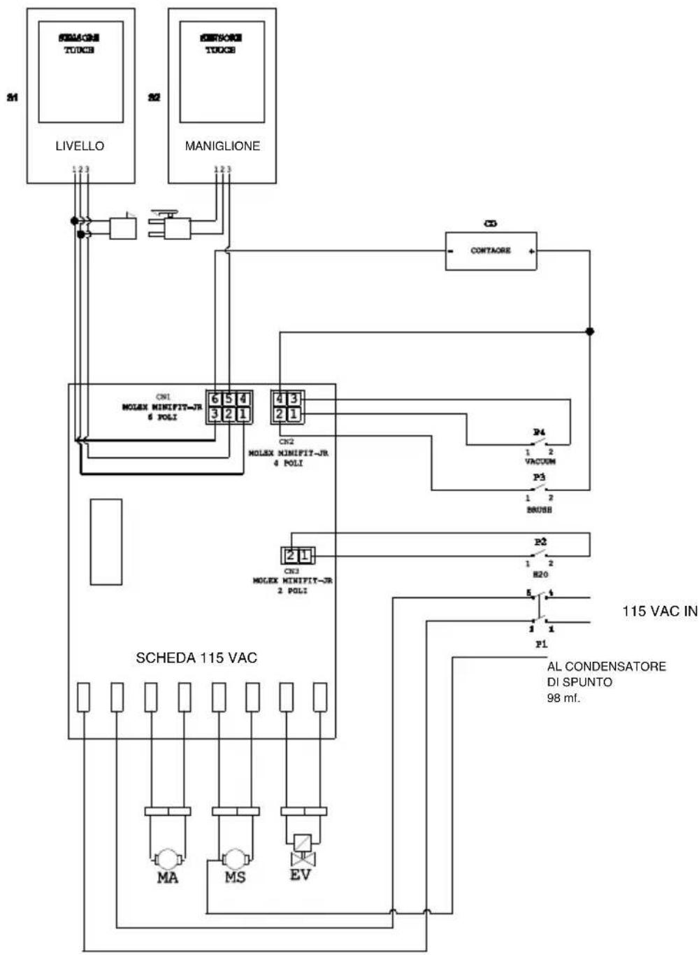
FR 30 - FR 45 TOUCH 115 VAC
flowchart
graph TD
    A["LIVELLO"] -->|1.23| B["MA"]
    C["MANIGLIONE"] -->|1.23| D["MS"]
    E["SCHEDA 115 VAC"] --> F["MOLEX MINIFIT-JR 4 POLI"]
    F --> G["MOLEX MINIFIT-JR 6 POLI"]
    G --> H["MOLEX MINIFIT-JR 2 POLI"]
    H --> I["MOLEX MINIFIT-JR 4 POLI"]
    I --> J["MOLEX MINIFIT-JR 6 POLI"]
    J --> K["MOLEX MINIFIT-JR 2 POLI"]
    K --> L["MOLEX MINIFIT-JR 4 POLI"]
    L --> M["MOLEX MINIFIT-JR 6 POLI"]
    M --> N["MOLEX MINIFIT-JR 2 POLI"]
    N --> O["MOLEX MINIFIT-JR 4 POLI"]
    O --> P["MOLEX MINIFIT-JR 6 POLI"]
    P --> Q["MOLEX MINIFIT-JR 2 POLI"]
    Q --> R["MOLEX MINIFIT-JR 4 POLI"]
    R --> S["MOLEX MINIFIT-JR 6 POLI"]
    S --> T["MOLEX MINIFIT-JR 2 POLI"]
    T --> U["MOLEX MINIFIT-JR 4 POLI"]
    U --> V["MOLEX MINIFIT-JR 6 POLI"]
    V --> W["MOLEX MINIFIT-JR 2 POLI"]
    W --> X["MOLEX MINIFIT-JR 4 POLI"]
    X --> Y["MOLEX MINIFIT-JR 6 POLI"]
    Y --> Z["MOLEX MINIFIT-JR 2 POLI"]
    Z --> AA["MOLEX MINIFIT-JR 4 POLI"]
    AA --> AB["MOLEX MINIFIT-JR 6 POLI"]
    AB --> AC["MOLEX MINIFIT-JR 2 POLI"]
    AC --> AD["MOLEX MINIFIT-JR 4 POLI"]
    AD --> AE["MOLEX MINIFIT-JR 6 POLI"]
    AE --> AF["MOLEX MINIFIT-JR 2 POLI"]
    AF --> AG["MOLEX MINIFIT-JR 4 POLI"]
    AG --> AH["MOLEX MINIFIT-JR 6 POLI"]
    AH --> AI["MOLEX MINIFIT-JR 2 POLI"]
    AI --> AJ["MOLEX MINIFIT-JR 4 POLI"]
    AJ --> AK["MOLEX MINIFIT-JR 6 POLI"]
    AK --> AL["MOLEX MINIFIT-JR 2 POLI"]
    AL --> AM["MOLEX MINIFIT-JR 4 POLI"]
    AM --> AN["MOLEX MINIFIT-JR 6 POLI"]
    AN --> AO["MOLEX MINIFIT-JR 2 POLI"]
    AO --> AP["MOLEX MINIFIT-JR 4 POLI"]
    AP --> AQ["MOLEX MINIFIT-JR 6 POLI"]
    AQ --> AR["MOLEX MINIFIT-JR 2 POLI"]
    AR --> AS["MOLEX MINIFIT-JR 4 POLI"]
    AS --> AT["MOLEX MINIFIT-JR 6 POLI"]
    AT --> AU["MOLEX MINIFIT-JR 2 POLI"]
    AU --> AV["MOLEX MINIFIT-JR 4 POLI"]
    AV --> AW["MOLEX MINIFIT-JR 6 POLI"]
    AW --> AX["MOLEX MINIFIT-JR 2 POLI"]
    AX --> AY["MOLEX MINIFIT-JR 4 POLI"]
    AY --> AZ["MOLEX MINIFIT-JR 6 POLI"]
CO ....Hour counter
CN 1 ......Sensor board connector
CN 2 ...... switch board connector
CN 3 ......EV switch board connector
MA......Vacuum motor
MS ....Brush motor
EV......Solenoid
P1....Switch
P2....EV Switch
P3 Brush switch
P4 Vacuum switch
S1 ...... Recovery level touch sensor
S2 ...... Handle touch sensor
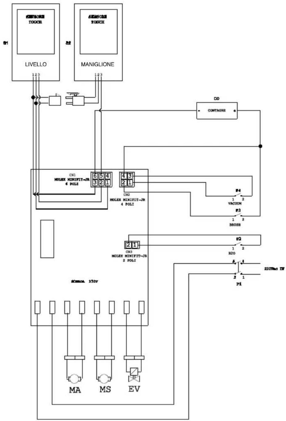
FR 30 - FR 45 TOUCH 230 VAC
flowchart
graph TD
    A["LIVELLO"] -->|1 2 3| B["ANDSORI TOUCH"]
    C["MANIGLIONE"] -->|1 2 3| D["ANDSORI TOUCH"]
    E["CONTAGORE"] --> F["DO"]
    G["MOLEX MINIFIT-JR 4 POLI"] --> H["CN1 MOLEX MINIFIT-JR 4 POLI"]
    I["MOLEX MINIFIT-JR 4 POLI"] --> J["CN2 MOLEX MINIFIT-JR 4 POLI"]
    K["MOLEX MINIFIT-JR 2 POLI"] --> L["CN3 MOLEX MINIFIT-JR 2 POLI"]
    M["MA"] --> N["ACOMA 130V"]
    O["MS"] --> P["ACOMA 130V"]
    Q["EV"] --> R["ACOMA 130V"]
    S["VACUUM"] --> T["F4"]
    U["H2O"] --> V["F2"]
    W["P1"] --> X["P1"]
    Y["230V AC TV"] --> Z["P1"]
CO ....Hour counter
CN 1 ......Sensor board connector
CN 2 ...... switch board connector
CN 3......EV switch board connector
MA......Vacuum motor
MS ....Brush motor
EV......Solenoid
P1 .... Switch
P2....EV Switch
P3 Brush switch
P4 Vacuum switch
S1 ...... Recovery level touch sensor
S2 ...... Handle touch sensor
Cher client,
Fig. C = position correct
PROBLEMAS - CAUSAS - SOLUÇÕES
PROBLEEM - OORZAAK - OPLOSSING
2.1 POPIS STROJE (Obr. 1)
2.1 BUDOWA MASZYNY (Rys. 1)
For the proper operation of the level sensors it is required to properly clean the inside of the tank (14 Rys. 14).
8.1 ROZŁADUNEK ZUŻYTEJ WODY
(Rys. 12)
9.1 VEDLIKEHOLD OG RENGJ∅RING

ADVARSEL:
- Remonter alt, fortsetter i revers.
OPERASJONER SOM SKAL UTF∅RES INNE N∅D
9.1.d - Rengjøring filter for rent vannr (Fig. 15)

MERK:
2.1 OPIS STROJA (Obr. 1)
Professional Cleaning Machines Since 1968
DEALER
GHIBLI & WIRBEL S.p.A.
Registered office:
Via Enrico Fermi, 43 - 37136 Verona (VR) - Italy
Headquarters: