
HS R 130 - Sweeper Ghibli & Wirbel - Free user manual and instructions
Find the device manual for free HS R 130 Ghibli & Wirbel in PDF.

| Brand | Ghibli & Wirbel |
| Model | HS R 130 |
| Category | Ride-on sweeper |
| Power supply | Battery 24 V DC, 2.3 kW |
| Battery | 4 x 6 V, 320 Ah/5h (acid) |
| Recommended charger | 24 V DC, 40 A |
| Central brush width (cleaning path) | 780 mm |
| Width with 1 side brush | 1158 mm |
| Width with 2 side brushes | 1270 mm |
| Waste container capacity | 115 L |
| Max waste weight (standard / DSA version) | 60 kg / 95 kg |
| Net weight (standard version) | 565 kg |
| Net weight (DSA version) | 638 kg |
| Standard dimensions (L x W x H) | 1550 x 1158 x 1340 mm (with side brush) |
| Height with operator roof | 2150 mm |
| Max forward speed | 6.5 km/h |
| Working speed | 4 km/h |
| Max slope | 20% |
| Max cleaning area (with 2 side brushes) | 9700 m²/h |
| Filtration type | Pocket filter (5.5 m²) or cartridge filter (6.4 m²) |
| Sound level (LwA measured / guaranteed) | 85 dB(A) / 86 dB(A) |
| Main functions | Central brush, side brush, suction, filter shaker, horn, work lights, parking brake, emergency stop |
| Unloading type | Manual or assisted (DSA/BIN-UP) |
| Maintenance | Check dust seals every 90-120 h, clean filters every 60-100 h, check brushes according to use |
| Safety | Automatic stop if operator leaves seat, emergency button, safety devices for raised container |
Frequently Asked Questions - HS R 130 Ghibli & Wirbel
User questions about HS R 130 Ghibli & Wirbel
0 question about this device. Answer the ones you know or ask your own.
Ask a new question about this device
Download the instructions for your Sweeper in PDF format for free! Find your manual HS R 130 - Ghibli & Wirbel and take your electronic device back in hand. On this page are published all the documents necessary for the use of your device. HS R 130 by Ghibli & Wirbel.
USER MANUAL HS R 130 Ghibli & Wirbel
TRIER LES DÉCHETS SEPARATE THE WASTE DIFFERENZIA I RIFIUTI
HS R 130 / BC HS R 130 ADM / BC ADM
natural_image
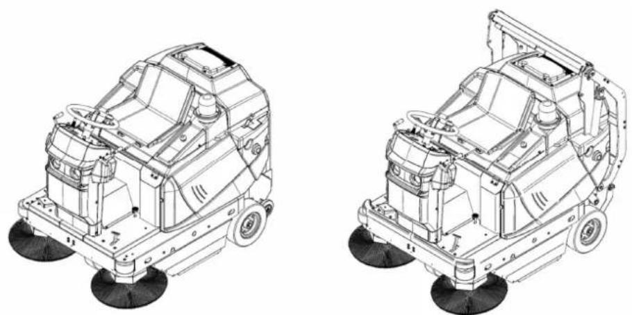
Technical line drawings of two industrial cleaning machines with visible structural components and wheels (no text or symbols)MANUALE USO E MANUTENZIONE Motoscopa
IT pag. 20
INSTRUCTIONS AND OPERATING MANUAL Sweeper
EN pag. 46
MANUEL D'INSTRUCTION Motobalayeuse
FR agFR pagep
HS R 130 HS R 130 ADM
PIC4
PIC5
natural_image
Technical line drawing of a mechanical device with multiple side-view components (no text or symbols)PIC6
natural_image
Technical line drawing of a cleaning or cleaning machine with directional arrows indicating motion (no text or symbols present)PIC7
PIC8
natural_image
Line drawing of a robotic cleaning machine with a human figure operating it (no text or symbols)PIC9
natural_image
Technical line drawing of a mechanical assembly with two black arrows indicating directional flow or movement (no text or symbols present)PIC10

PIC11
natural_image
Technical line drawing of a mechanical device with gears and housing (no text or symbols)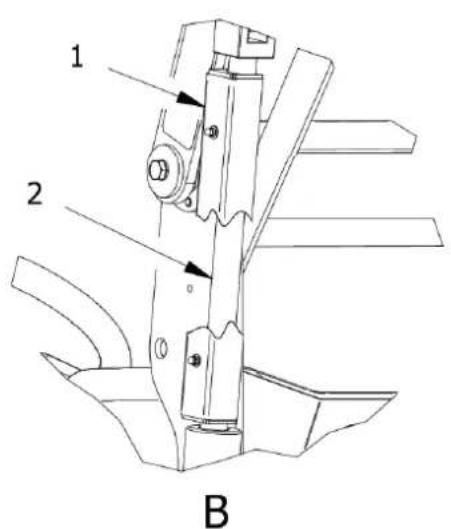
natural_image
Technical line drawing of a mechanical lift or pump assembly with labeled component B, showing internal components and motion arrows (no text or symbols beyond labels)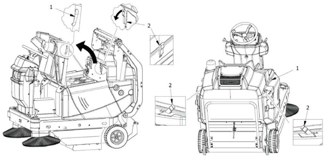
PIC13
natural_image
Technical line drawing of a mechanical cleaning or anti-mile-worm system with exploded and assembled views (no text or symbols)PIC14
PIC15
PIC16
natural_image
Technical line drawing of a cleaning or cleaning vehicle with labeled components (no text or symbols present)PIC17
1
PIC18
2
PIC19
natural_image
Diagram showing a fan icon connected to a hexagonal button with directional arrows (no text or symbols)PIC20
natural_image
Close-up of a camera control panel with a black download arrow and a small icon (no text or symbols)PIC21PIC22
natural_image
Technical line drawing of a mechanical device with a brush and directional arrow (no text or symbols)PIC23
natural_image
Technical line drawing of a mechanical device with a close-up inset showing a bracket assembly (no text or symbols)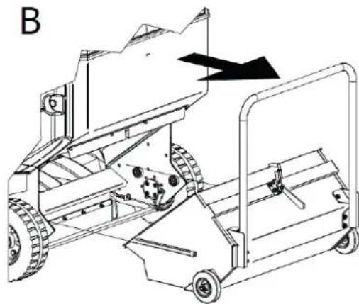
natural_image
Technical line drawing of a mechanical device with gears and a handle, showing no text or symbols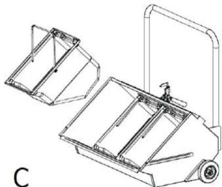
natural_image
Technical line drawing of a mechanical device with two views (top and side), no text or symbols present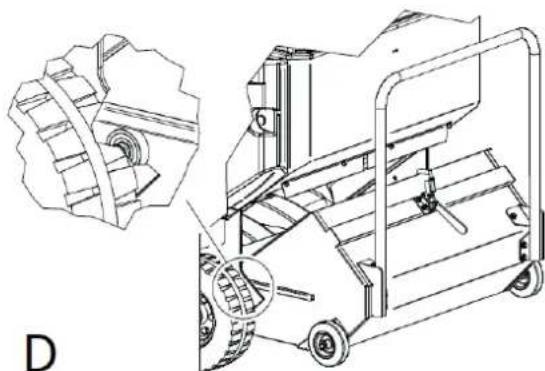
natural_image
Technical line drawing of a mechanical device with gear and wheel components, shown from two different angles (no text or symbols)PIC24
PIC 26
PIC 27
PIC 28

natural_image
Technical line drawing of a cleaning or cleaning vehicle with multiple wheels and structural components (no text or symbols)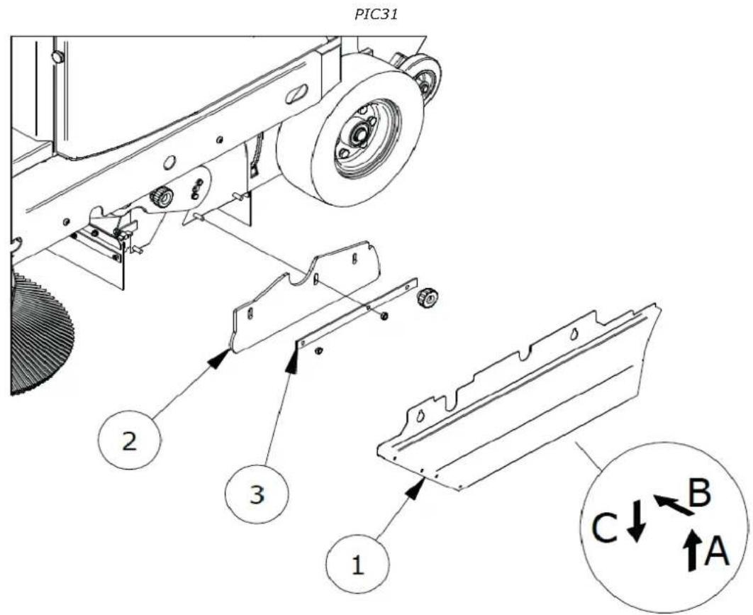
PIC32
PIC34
natural_image
Technical line drawing of a cleaning or cleaning machine with a control panel and labeled component (no text or symbols present)PIC 35
PIC36
indice....pag.
CAPITOLO 1 - SCOPI / INTENZIONI. 22
CAPITOLO 2 - LEGENDA....22
CAPITOLO 3 - NORME GENERALI 24
9.1. CORRECT USE AND TIPS....57
9.2. TRAINING OF OPERATORS....58
9.3. OPERATIONAL START-UP....58
9.4. TRAVEL 58
9.5. OPERATIONAL SHUTDOWN 59
9.6. PARKING....59
9.7. EMERGENCY STOP 59
9.8. CENTRAL BRUSH 59
9.9. SIDE BRUSH 59
9.10. SUCTION....59
9.11. FILTER SHAKER 59
9.12. HORN SWITCH....59
9.13. FLAP RAISE 60
9.14. EMPTYING THE WASTE CONTAINER 60
9.14.1. MANUAL DISCHARGE VERSION 60
9.14.2. VERSION WITH ASSISTED DISCHARGE (DSA, BIN-UP MODELS) 60
9.15. RECHARGING THE BATTERY (BATTERY-POWERED VERSION) 60
CHAPTER 10 - ADJUSTMENTS. 60
10.1. TRAINING OF OPERATORS....61
10.2. ADJUSTING THE CENTRAL BRUSH ACTION 61
10.3. ADJUSTING THE HEIGHT OF THE SIDE DUST SEALS. 61
CHAPTER 11 - SAFETY RULES. 61
11.1. GENERAL RESIDUAL RISKS 61
11.2. GENERAL RISKS FOR ACID BATTERIES 62
11.3. PROTECTIVE MEASURES 62
11.3.1. PERSONAL PROTECTION EQUIPMENT (PPE) 62
11.3.2. PROTECTIVE MEASURES FOR THE WASTE CONTAINER EMPTYING OPERATION 63
CHAPTER 12 - STABILITY OF THE MACHINE 63
12.1. STABILITY DURING USE 63
12.2. STABILITY DURING TRANSPORTATION 64
CHAPTER 13 - TRANSPORTATION, HANDLING AND DECOMMISSIONING 64
13.1. DECOMMISSIONING....64
13.2. PACKAGING, LIFTING AND TRANSPORTATION 64
CHAPTER 14 - EMERGENCY SITUATIONS 64
14.1. EMERGENCY SITUATIONS 64
14.2. STARTING AFTER AN EMERGENCY SITUATION....65
CHAPTER 15 - MAINTENANCE....65
15.1. GENERAL SAFETY RULES....65
15.2. TRAINING OF OPERATORS....65
15.3. DUST SEALS 65
15.4. CENTRAL BRUSH 66
15.5. SIDE BRUSH 66
15.6. SPECIFIC MAINTENANCE FOR INTERNAL COMBUSTION ENGINES 66
15.7. SPECIFIC MAINTENANCE FOR ACID BATTERIES 67
15.8. CLEANING THE MACHINE 67
15.9. CLEANING OF FILTERS 67
15.9.1. BAGS FILTERS 67
15.9.2. CARTRIDGE FILTERS....68
15.10. CLEANING THE WASTE CONTAINER 68
CHAPTER 16 - EXTRAORDINARY MAINTENANCE 68
CHAPTER 17 - SPARE PARTS. 68
CHAPTER 18 - DISMANTLING AND DEMOLITION. 68
CHAPTER 19 - DEFECTS / CAUSES / SOLUTIONS 69
CHAPTER 20 - WARRANTY 69
CHAPTER 21 - EC DECLARATION OF CONFORMITY 69
CHAPTER 1 - PURPOSES / INTENTIONS
The company is pleased to be able to consider you one of the owners of a motorsweeper.
Following the instructions below, we are sure you will fully appreciate the working possibilities of this motorsweeper.
This instruction manual is provided to instruct and defi ne as clearly as possible the purposes and intentions for which the machine was built and for use in the context of maximum safety.
You will also find listed all those minor operations necessary to keep the motorsweeper efficient and safe.
Always contact specialised personnel for extraordinary maintenance operations (par. CHAPTER 16).
You will find information on the residual hazards or risks, that is, all those risks that cannot be eliminated, with the appropriate instructions for each case. There will be information on the permitted and not permitted uses, indications on the commissioning of the motorsweeper, technical indications and permitted performances, indications on the use of the motorsweeper and its maintenance, indications for decommissioning and for dismantling or demolition.
CHAPTER 2 - LEGEND
The following symbols are used in this manual and on the machine, which can be found individually or combined.
 | Indicates a warning or note about key functions or useful functions. Pay close attention to the text blocks indicated by this symbol. |
 | Indicates a note about key functions or useful functions. |
 | Indicates the need to consult the use and maintenance manual before carrying out any operation |
 | Indicates that the information where the symbol is displayed relates to maintenance. |
 | Indicates that the equipment is suitable for direct current only. |
 | Indicates the danger of inhalation of exhaust fumes deriving from the use of combustion engines in inadequately ventilated areas. |
 | Wear eye protection. |
 | Wear ear protectors. |
 | Wear protective gloves. |
 | Wear protective clothing. |
 | Wear a respiratory protective mask. |
 | Wear safety footwear. |
 | Fasten the seat belt |
 | ASSISTED DISCHARGE VERSIONS |
Refer to the specific manuals of the machine parts (e.g. engine, batteries, etc.) for further symbols not shown in this document.
CHAPTER 3 - GENERAL RULES

BEFORE USING THE MACHINE READ THIS INSTRUCTION MANUAL CAREFULLY.
THE COMPANY DECLINES ANY LIABILITY FOR DAMAGE TO PROPERTY AND/OR PERSONS RESULTING FROM FAILURE TO COMPLY WITH THE RULES LISTED IN THIS MANUAL OR FROM IRREGULAR AND/OR IMPROPER USE OF THE MACHINE.
THIS MACHINE IS NOT INTENDED FOR USE BY PERSONS (INCLUDING CHILDREN) WITH REDUCED PHYSICAL, SENSORY OR MENTAL CAPABILITIES, OR LACK OF EXPERIENCE AND KNOWLEDGE.
CHILDREN SHOULD BE SUPERVISED TO ENSURE THAT THEY DO NOT PLAY WITH THE APPLIANCE.
IN ORDER TO PREVENT UNAUTHORISED USE OF THE MACHINE, THE DRIVING FORCE MUST BE SWITCHED OFF OR MADE SAFE, FOR EXAMPLE BY REMOVING THE IGNITION KEY.
THE MACHINE LEFT UNATTENDED MUST BE MADE SAFE AGAINST INVOLUNTARY MOVEMENTS.
THIS MACHINE IS INTENDED FOR COMMERCIAL USE, FOR EXAMPLE IN HOTELS, SCHOOLS, HOSPITALS, FACTORIES, SHOPS, OFFICES AND RENTAL BUSINESSES AND IN LARGE SPACES IN GENERAL.
IN ADDITION, THE MACHINE:
• CAN BE USED INDOORS WITHOUT RESTRICTIONS;
- MUST NOT BE USED OR KEPT OUTSIDE IN HUMID CONDITIONS OR EXPOSED DIRECTLY TO RAIN;
- MUST BE STORED UNDER COVER.
ALL THE TOOLS THAT WILL BE NECESSARY FOR PERSONAL PROTECTION (GLOVES, MASKS, GLASSES, WHITE LENSES, KEYS AND TOOLS) ARE SUPPLIED BY THE USER.
FOR YOUR CONVENIENCE, PLEASE REFER TO THE TABLE OF CONTENTS.
FOR FURTHER REFERENCE, ALWAYS KEEP THIS MANUAL WITH YOU (IN CASE OF LOSS, IMMEDIATELY REQUEST A COPY FROM YOUR DEALER).
THE COMPANY RESERVES THE RIGHT TO MAKE CHANGES OR IMPROVEMENTS TO THE MACHINES OF ITS OWN PRODUCTION WITHOUT THE OBLIGATION ON ITS PART TO IMPLEMENT THE SAME ON THE MACHINES PREVIOUSLY SOLD.
CHAPTER 4 - PREPARATION(UNPACKING)
The motorsweeper is delivered packed on top of its pallet and comes with the side brush/brushes disassembled. After removing the outer packaging, the machine must be removed from the pallet:
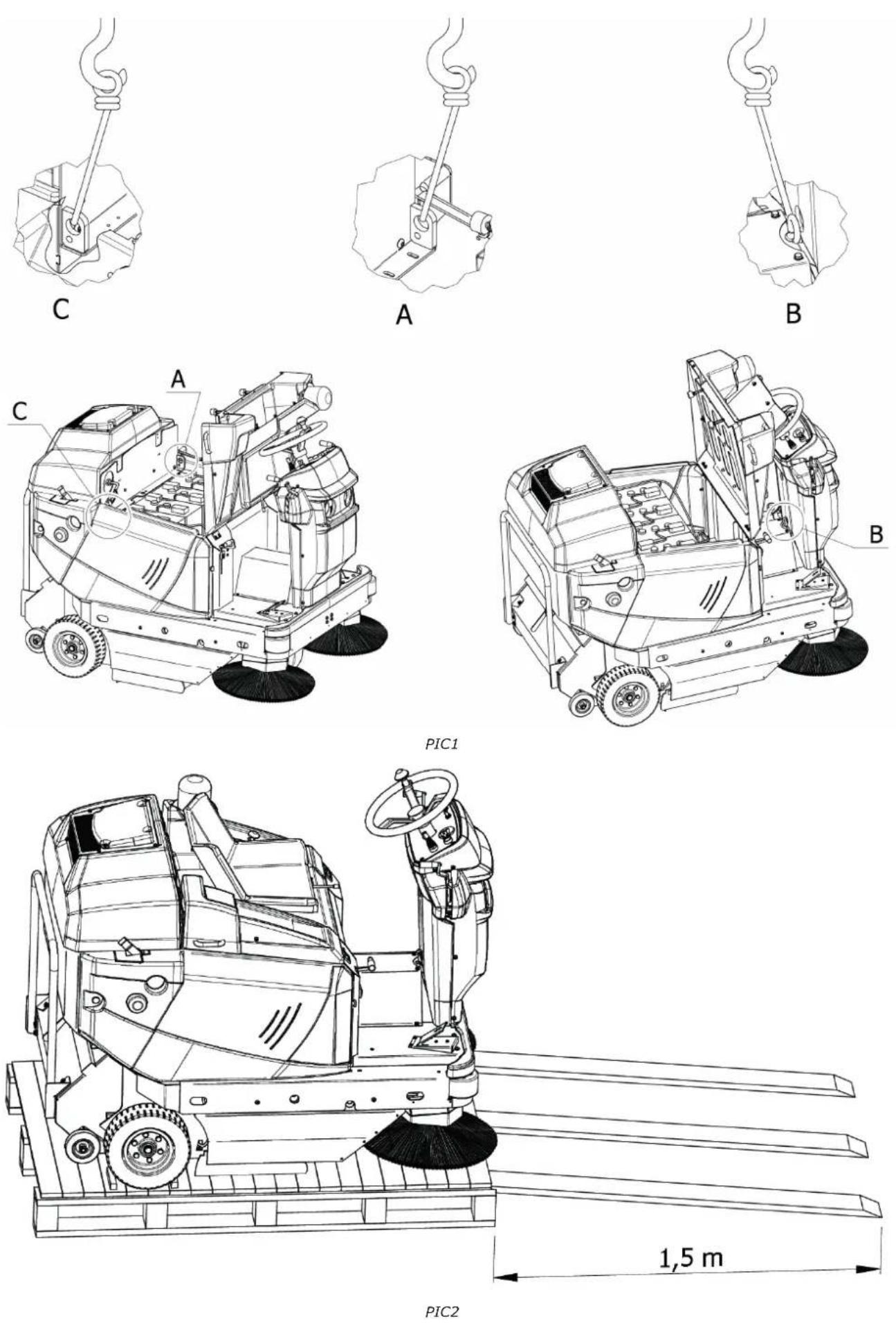
- Lifting devices: Raise the engine hood. Subsequently, use three slings equipped with hooks, of which the one hooked to the eyebolt is longer than 40cm compared to the other two. These slings must be chosen according to the weight indicated on the CE plate. Then lift the machine from the pallet with the lifting means suitable for the weight of the machine displayed on the CE plate. Attach them to the points A, B, C PIC 1. Lay the machine on the ground very slowly avoiding it being struck. Close the motor hood.
- Inclined surface or descent platforms (operation to be performed without persons in front of the machine and on a wide flat surface): Use an inclined surface, or three platforms, with a capacity suitable for the weight of the machine indicated on the CE plate and which is at least 1.5m long to avoid damaging the dust seals. Install it adhering to the narrow side of the pallet PIC 2. Remove the wheel locks, see § 9.6.
At the end of the unpacking operation and assemble the side brush/brushes, as illustrated in paragraph § 15.5.

IMPORTANT: All waste materials resulting from the unpacking operation must be disposed of by the user, following the specific disposal regulations currently in force.

CHECK THAT THE PROTECTIONS ARE PERFECTLY INTACT AND CORRECTLY ASSEMBLED; IN CASE OF DEFECTS OR MISSING ELEMENTS DO NOT PROCEED WITH START-UP AND IMMEDIATELY CONTACT THE DEALER OR THE PARENT COMPANY.
CHAPTER 5 - MACHINEDESCRIPTION
5.1. OPERATION AND MAIN PARTS
The machine has been designed for the cleaning and removal of dust and dirt generally present on hard, not excessively uneven fl at surfaces such as: cement, asphalt, stoneware, ceramic, wood, sheet metal, marble, rubber or plastic rugs in general, ashlar or smooth, synthetic or short pile fi bre carpets.
The motor sweeper is controlled by an operator on board the machine and, depending on the version, it can have manual rear discharge or assisted rear discharge (DSA, BIN UP models).
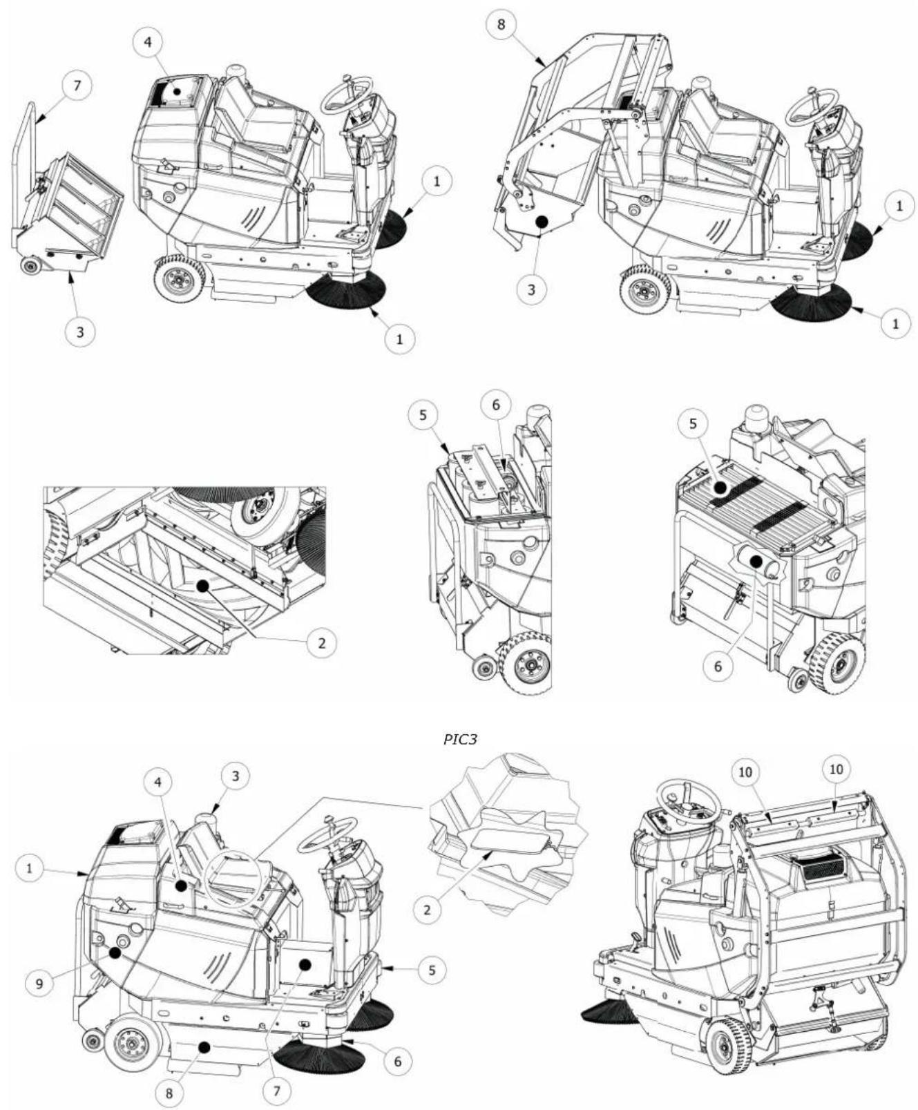
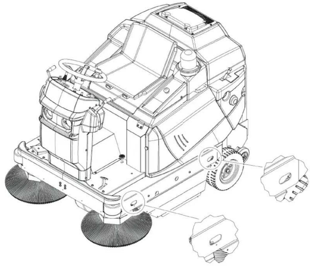
Removal of the coarsest dirt takes place through the action of the rotating brushes (Item 1 and 2 PIC 3) while finer dirt is removed through a suction system (Item 4 PIC 3), which also prevents the formation of dust due to the action of the brushes.
In particular, the machine is equipped with a side brush (Item 1 PIC 3; operator left side brush on request) that convey the dirt to the centre of the machine, and a cylindrical rotating central brush (Item 2 PIC 3), assembled transversely to the machine, which removes dirt by discharging it into the waste container located on the rear of the machine (Item 3 PIC 3). The finest debris, instead, is trapped in the filter system (Item 5 PIC 3) and dropped into the waste container thanks to the filter shaker (Item 6 PIC 3).
The machine operates through a battery motor.
Finally, in the suitably equipped versions, a hydraulic lifting system allows the operator to empty the waste container when it is full.
All the brushes present are adjustable and can be disconnected by the operator through dedicated controls.
5.2. SAFETY PROTECTIONS AND DEVICES
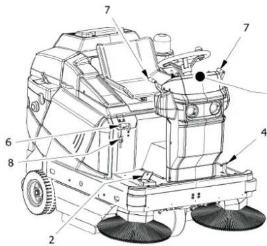
As shown in PIC 4, it is possible to see the safety protections and devices that must be intact and carefully fitted. The machine must not be used with damaged or missing protections or without safety devices that are not intact and functioning correctly. A description of the protections and safety devices is therefore provided below.
| ITEM No. | DESCRIPTION PIC 4 |
| 1 | Filter casing |
| 2 | Man present safety micro |
| 3 | Flashing light |
| 4 | Engine hood |
| 5 | Bumper wheel |
| 6 | Side brush casing |
| 7 | Hydraulic hose casing |
| 8 | Central brush protection side |
| 9 | RT and LT side |
| 10 | Seat for waste container locking pin |
5.3. SIDE BRUSH
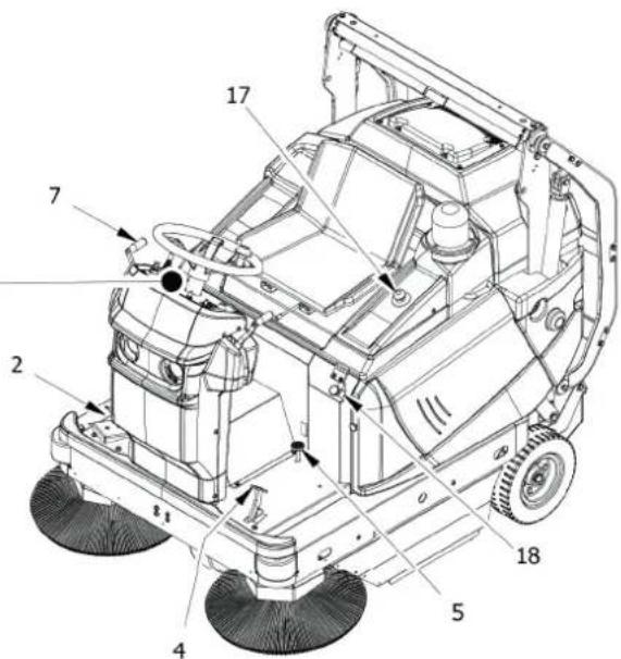
The side brush is installed on the operator side, Item 1 PIC 5, acts as a conveyor of dust and debris, and is designed primarily for the cleaning of edges, corners and profi les. It is possible to disengage each brush through a dedicated command. It is available in different hardness and nature of the bristles, depending on the type of material to be collected or the flooring.
On request, the additional side brush installed on the opposite side is installed.

IMPORTANT: Do not touch the side brush with your hands during rotation and do not collect fi lamentary materials (wires, ropes, etc.)
5.4. CENTRALBRUSH
The central brush Item 2 PIC 5 is the main part of the machine and allows the loading of dust and debris into the waste container. It is available in different hardness and nature of the bristles, depending on the type of material to be collected or the flooring. It is adjustable in height when worn.

IMPORTANT: Do not collect cords, wires, packing straps, sticks, etc. longer than 25 cm because they could wrap around the central and side brush and then damage it.
5.5. DUST SEALS
The dustproof seals (Item 3 PIC 5), front (mobile, Item 4 PIC 5) and rear (Item 5 PIC 5) surround the central brush and are very important for correct functioning of the machine as they allow dust to be suctioned in; it is important to check its condition often.
5.6. SUCTION SYSTEM
The suction system (Item 4 PIC 3) allows collection of the finest debris and prevents the formation of dust that can form by the action of the brushes.
5.7. FILTERING SYSTEM
The filtering system is obtained by means of a pocket filter or a cartridge filter (Item 5 PIC 3) and traps the fi nest particles that are suctioned in by the suction system and prevents dust from spreading into the outside environment. A shaking system (Item 6 PIC 3) is used to release debris inside the waste container recleaning the fi Iters.
5.8. WASTE CONTAINER
The waste container (Item 3 PIC 3) is used to contain all the material collected by the central brush and the dust of the filters.
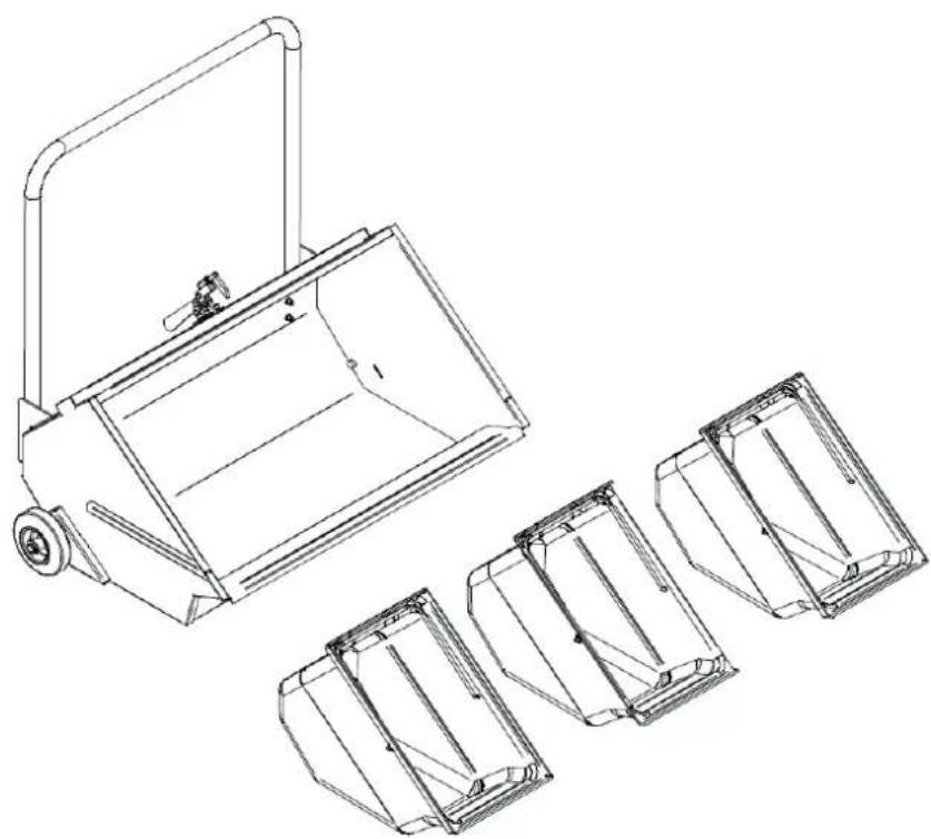
- In the manual emptying version, the container is equipped with a handle for extraction from the machine and inside there are three plastic drawers that facilitate emptying (PIC 6).
- In the assisted discharge version, it is operated by actuators that allow it to be emptied and is equipped with a safety lock system (Item 10 PIC 4, § 6.4.1) in the fully open position.
5.9. BATTERY
The battery (Item 1 PIC 8) powers the propulsion, the hydraulic system for lifting of the waste container and all the remaining services of the motorsweeper. It can be recharged using the dedicated plug (Item 2 PIC 8). The artery can be accessed by lifting the engine hood (Item 4 PIC 8).
| TECHNICAL CHARACTERISTICS | ||
| Power supply // | BATTERY | |
| Rated power / rated voltage kW / V | 2.3 / 24 DC | |
| Width central brush /Cleaning track mm | 780 x ∅310 | |
| Max advancement speed km/h | 6,5 | |
| Max. reverse speed Km/h | 3 | |
| Working speed Km/h | 4 | |
| Maximum cleaning capacity (with no. 2 side brushes) sqm/h | 9700 | |
| Maximum slope % | 20 | |
| Drive // | Front | |
| Transmission // | Electric | |
| Minimum distance for reversing between two walls mm | 2500 | |
| Filtering surface (no. 1 pocket filter) sqm | 5.5 | |
| Filtering surface (no. 8 cartridge filters) sqm | 6.4 | |
| Container capacity | L | 115 |
| Maximum permissible waste weight | kg | 60 (95 DSA) |
| Maximum length with side brush | mm | 1550 (1630 DSA) |
| Maximum width (with no. 1 side brush) | mm | 1158 |
| Maximum width (with no. 2 side brushes) | mm | 1270 |
| Standard version height | mm | 1340 (1430 DSA) |
| Height with operator roof | mm | 2150 |
| Net weight , standard vers ^1 | kg | 565 (638 DSA) |
| Gross Vehicle Weight ^2 | kg | 927 (1035 DSA) |
| Transportation weight ^3 | kg | 625 (773 DSA) |
| Measured sound power level LwA | dB | 85 |
| Guaranteed sound power level LwA | dB | 86 |
| Uncertainty | dB | 1,5 |
| Sound pressure level LpA | dB(A) | 75 |
| Instantaneous sound pressure (maximum value) | dB(C) | < 130 |
| Internal body vibration a_w | m/s ^2 | 0,64 |
| Uncertainty m/s | ^2 | 0,09 |
| Hand-arm vibration a_hw | m/s ^2 | 2,34 |
| Uncertainty | m/s ^2 | 1,08 |
CHAPTER 6 - WORK STATION AND CONTROLS
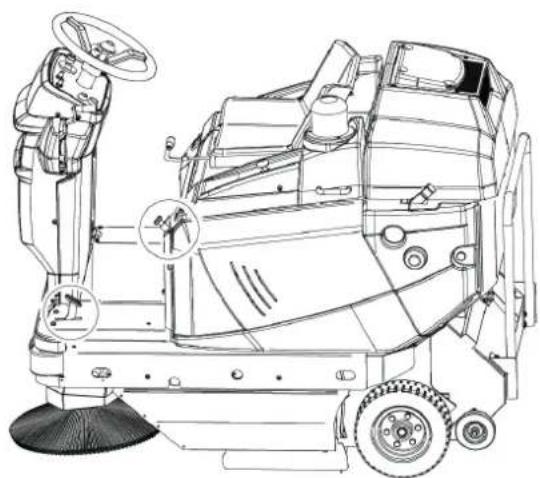
6.1. WORKPLACEPOSITION
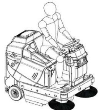
The workplace that must be occupied by the operator during use of the machine is only that shown in PIC 9. All the manual and pedal controls for use of the machine are located at the operator's seat.

IMPORTANT: For safety reasons, the machine switches off automatically if the operator gets up from the driving position.
6.2. OPERATOR COMFORT
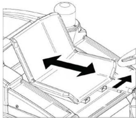
To ensure correct posture and the desired degree of comfort during use of the machine it is possible to adjust the stroke of the seat, using the lever (PIC 10).
6.3. CONTROL DEVICES
6.3.1. POSITION OF THE CONTROLS AND DESCRIPTION
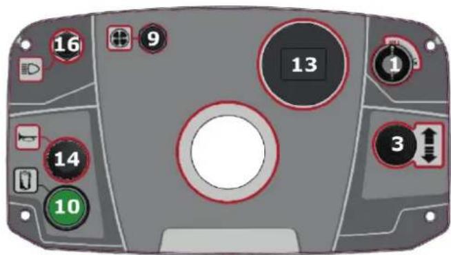
As mentioned in para.§ 6.1, the control devices are located at the operator seat. PIC 11 displays the description and position of the operator controls and a detailed description below.
| Item DESCRIPTION PIC 11 |
| 1 Starter key |
| 2 Throttle |
| 3 Gear selector (forward, backward) |
| 4 Brake |
| 5 Flap raise |
| 6 Central brush control |
| 7 Side brush lever |
| 8 Central brush action regulator |
| 9 Suction switch |
| 10 Filter shaker switch |
| 11 Waste container control |
| 12 Waste container opening command |
| 13 hour meter |
| 14 Horn |
| 15 Hydraulic consent switch |
| 16 Work lights switch |
| 17 Emergency button |
| 18 Parking Brake |
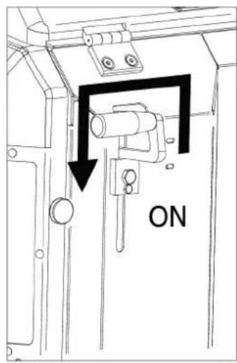
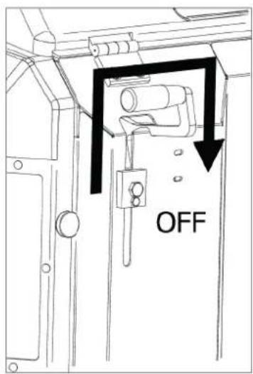
6.3.2. STARTER KEY
Through the action on the key switch (Item 1 PIC 11) it is possible to start the engine and stop it (PIC 15). It is also possible to remove the key.
6.3.3. THROTTLE. ACCELERATOR PEDAL
The accelerator pedal (Item 2 PIC 11) is operated by pressing it. It manages the operation of the motorsweeper. The direction of travel (forward or reverse) will be decided from the position set via the travel selector (Item 3 PIC 11).
6.3.4. GEAR SELECTOR (FORWARD, BACKWARD)
The gear selector (Item 3 PIC 11, PIC 16) is used to control the direction of travel of the motorsweeper (forward, backward and neutral).
6.3.5. BRAKE PEDAL
Pressing the brake pedal, (Item 4 PIC 11) it is possible to act on the braking system of the motorsweeper, stopping its operation.
6.3.6. FLAP RAISE
The flap raise pedal (Item 5 PIC 11) allows the front seal to be lifted, making it possible to collect bulky and light objects (e.g. leaves, cans, cigarette packs, etc.).
6.3.7. CENTRAL BRUSH CONTROL
Through the control lever (Item 6 PIC 11) it is possible to raise or lower the central brush in order to ensure or not its cleaning action.
Using the SIDE BRUSH LEVER (Item 7 PIC 11) it is possible to configure the side brush in the working position (in contact with the surface to be cleaned) or at rest (in the raised position). Intermediate positions are not possible.
6.3.9. CENTRAL BRUSH ACTION REGULATOR
The central brush action regulator (Item 8 PIC 11) is represented by a slider along a slot that can be locked in place by rotating a screw. It is used to adjust the height of the central brush from the floor when it is fully lowered (working position), adjusting the action on the surface to be cleaned.
6.3.10. SUCTION SWITCH
By using the suction switch (Item 9 PIC 11) it is possible to operate and stop the suction system.
6.3.11. FILTER SHAKER SWITCH
Pressing the filter shaker button (Item 10 PIC 11) it is possible to operate the mechanism responsible for the falling of fi ne debris and dust trapped in the fi Iters. The switch is characterised by only one stable position.
6.3.12. WASTE CONTAINER CONTROL (DSA VERSION ONLY)
By pressing the control button (Item 11 PIC 11) the waste container ascent/descent device is activated.
6.3.13. WASTE CONTAINER OPENING CONTROL (DSA VERSION ONLY)
The control button (Item 12 PIC 11) is used to open or close the waste container. Respectively pressing it or releasing it in its only stable position, in which the container is always closed.
6.3.14. HOUR METER
The hour meter (Item 13 PIC 11) displays the working hours of the machine.
6.3.15. HORN SWITCH
When the button is pressed (Item 14 PIC 11) the horn is activated.
6.3.16. HYDRAULIC CONSENT SWITCH (DSA VERSION ONLY)
When the button is pressed (Item 15 PIC 11) the safety valve of the hydraulic system is released.
6.3.17. WORK LIGHTS SWITCH
The switch manages the switching on and off of the work light(s) (Item 16 PIC 11).
6.3.18. EMERGENCY BUTTON
The emergency button (Part. 17 PIC 11) operates to cut off power to all parts of the machine. It can be deactivated simply by lifting it.
6.3.19. PARKING BRAKE
This control (Part. 18 PIC 11) is used to keep the motorsweeper braked when not in Service.
6.4. USE OF SAFETY PROTECTIONS AND DEVICES
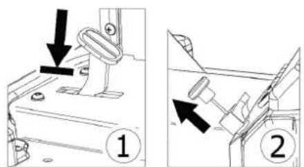
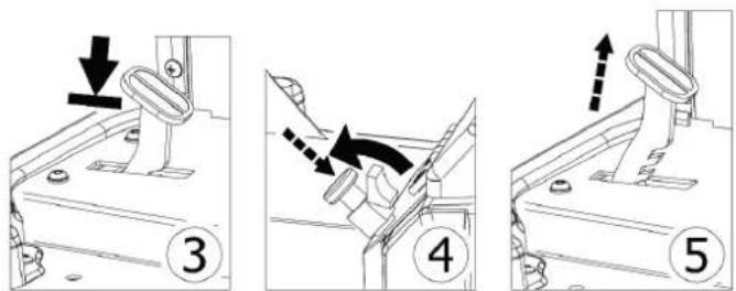
6.4.1. WASTE CONTAINER SAFETY DEVICES POSITIONING
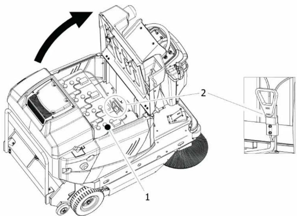
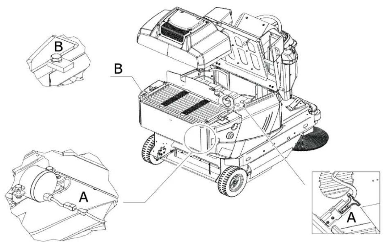
The safety devices (Item 1 PIC 8) prevents accidental closure of the waste container when it is lifted.
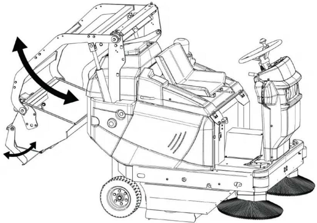
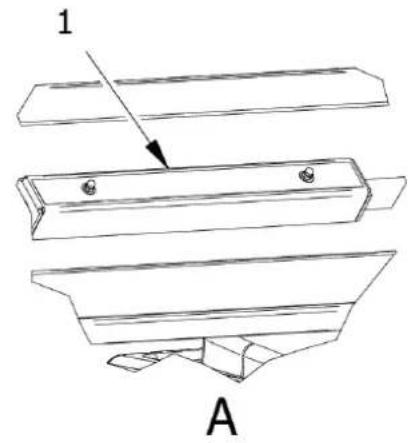
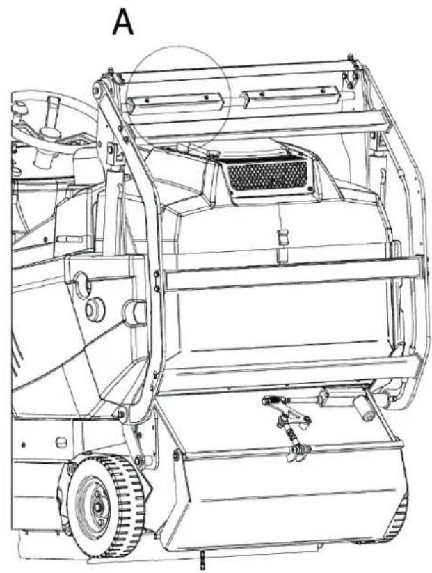
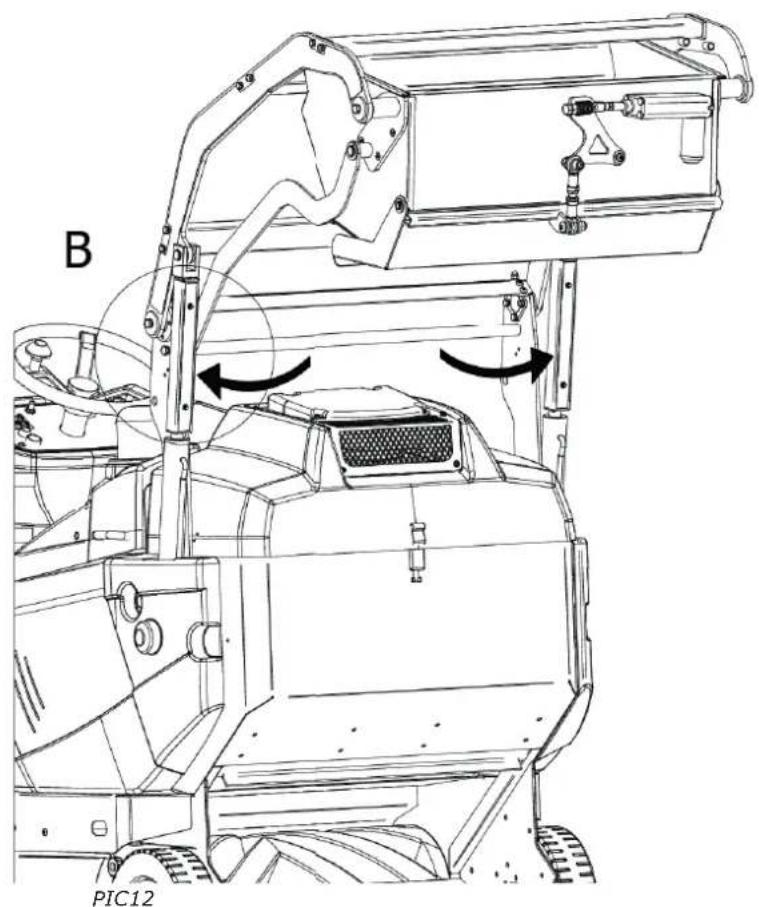
Them must be used for maintenance operations and for all those in which the container is expected to remain in a raised position with the possibility of persons or objects interfering or remaining below it. It is possible to install the safety devices as shown in (PIC 12):
Detach the safety devices from their original position (Item 1, A, PIC 12) and install them by pressure on the actuator rod (no.2, B, PIC 12) when they are completely extracted (B, PIC 12).

ALWAYS INSTALL BOTH SAFETY DEVICES.

MAKE SURE THAT THE SAFETY DEVICES HAS BEEN DISCONNECTED BEFORE LOWERING THE WASTE CONTAINER.
6.4.2. ENGINE HOOD AND FILTER CARTER
The engine hood (Item 1 PIC 4) and the filter casing (Item 2 PIC 4) can be easily opened to allow inspection and maintenance operations.
The engine hood can be opened using the appropriate handles.
The fi Iter casing can be opened by releasing the relative tie rods.
CHAPTER 7 - PERMITTED AND NON-PERMITTED CONDITIONS OF USE
7.1. PERMITTED CONDITIONS OF USE
The motorsweeper was created to clean processing residues, dust, dirt in general, all fl at, hard, not excessively uneven surfaces such as: cement, asphalt, stoneware, ceramic, wood, sheet metal, marble, rubber or plastic rugs in general, ashlar or smooth, synthetic or short pile fi bre carpets.
The permitted conditions of use are as follows.
Minimum operating temperature: -20°C (-4°F)
Maximum operating temperature: +38°C (+100.4°F)
Maximum front and side slope: para. § 5.10


REFER TO THE DOCUMENTATION PROVIDED BY THE BATTERY AND CHARGER MANUFACTURER FOR ADDITIONAL PERMITTED CONDITIONS OF USE.

IMPORTANT: Do not use and do not leave at rest with temperatures above +40°C (+104°F).

IMPORTANT: proceed with emptying, cleaning and maintenance of the machine only on fl at and regular fl ooring that allows perfect stability to the machine for the entire duration of all the afore-mentioned operations.
7.2. NON-PERMITTED CONDITIONS OF USE

ALWAYS ENSURE THAT THE SAFETY SUPPORT IS INSTALLED BEFORE WORKING BENEATH HOPPER. (ITEM. 1 PIC 8).

THIS MACHINE IS FOR DRY USE ONLY.


FOR MODELS WITH INTERNAL COMBUSTION ENGINE: DO NOT INHALE EXHAUST GAS FUMES. ONLY USE INDOORS WHEN ADEQUATE VENTILATION IS PROVIDED, AND WHEN A SECOND PERSON HAS BEEN INSTRUCTED TO LOOK AFTER YOU.

DO NOT USE FOR CLEANING PURPOSES ON SURFACES HAVING A GRADIENT EXCEEDING THAT MARKED ON THE MACHINE, SEE § 5.10

DO NOT USE THE MOTORISED BRUSH WHERE THERE IS A DANGER OF OBJECTS FALLING

IT CANNOT BE USED IN ENVIRONMENTS WHERE EXPLOSIVE OR FLAMMABLE MATERIALS ARE PRESENT.

THE MOTORSWEEPER CANNOT BE USED ON SLOPES GREATER THAN WHAT IS REPORTED.

IT CANNOT BE USED ON DIRT, GRAVEL OR VERY UNEVEN SURFACES.

IT CANNOT COLLECT OILS, POISONS AND CHEMICAL MATERIALS IN GENERAL, (IN THE CASE OF HAVING TO USE THE MACHINE IN CHEMICAL PLANTS REQUEST SPECIFIC AUTHORISATION THAT WILL BE PRODUCED BY THE RETAILER OR PARENT COMPANY).

IT CANNOT BE USED ON URBAN OR NON-URBAN ROADS AND MUST NOT TRAVEL ON ANY PUBLIC ROAD.

IT CANNOT BE USED IN POOR LIGHTING ENVIRONMENTS, EXCEPT FOR MODELS EQUIPPED WITH WORK LIGHTS.

IT CANNOT BE TOWED IN ANY WAY INCLUDING ON PRIVATE PREMISES AND ON PUBLIC ROADS OR IN PUBLIC PLACES.

IT CANNOT BE USED TO SWEEP SNOW OR TO WASH OR DEGREASE SURFACES IN GENERAL THAT ARE WET OR VERY WET.

IT CANNOT OPERATE IN THE PRESENCE OF SPINNING OR THE CONSTRUCTION OF FILIFORM MATERIALS BECAUSE THE NATURE OF THE MATERIAL TO BE COLLECTED IS INCOMPATIBLE WITH THE ROTATION OF THE BRUSHES.

IT CANNOT BE USED IN ANY WAY AS A SUPPORT FOR OBJECTS OR AS A RAISED FLOOR FOR PROPERTY AND PERSONS.

NEVER LET ANYONE APPROACH WITHIN RANGE OF THE MACHINE.

DO NOT MAKE CHANGES OF ANY KIND UNLESS AUTHORISED BY THE MANUFACTURER.


IN ADDITION, REFER TO THE DOCUMENTATION PROVIDED BY THE BATTERY AND CHARGER MANUFACTURER FOR ANY ADDITIONAL CONDITIONS OF USE THAT ARE NOT PERMITTED.
CHAPTER 8 - COMMISSIONING


BEFORE PROCEEDING, IT IS NECESSARY TO HAVE READ ALL THE PREVIOUS CHAPTERS.
8.1. CHECKS BEFORE FIRST START-UP
The motorsweeper is supplied ready for the first start-up by the user. Adjustments, inspections and functional tests have already been performed by the Manufacturer.
DSA, BIN-UP VERSIONS:
Carefully check the hydraulic oil level in the dedicated tank and, if necessary, top it up to the level shown (PIC 14) with ISO 46 L-HV oil (maximum quantity: 2,5 L).
There is no need for specific training of the operator with regard to the first start-up of the motorsweeper, except for the information contained in this manual.
8.3. FIRST START-UP
The first start-up of the motorsweeper is carried out in the same manner as described in paragraph § 9.3.
CHAPTER 9 - USING THE MACHINE


BEFORE PROCEEDING, IT IS NECESSARY TO HAVE READ ALL THE PREVIOUS CHAPTERS.
9.1. CORRECT USE AND TIPS

NEVER TOUCH THE SIDE BRUSH WITH YOUR HANDS DURING ROTATION

CHECK THAT THERE ARE NO PERSONS LESS THAN 2 METERS FROM THE MOTORSWEEPER DURING THE WASTE CONTAINER EMPTYING OPERATIONS. ALSO CHECK THAT THERE IS ADEQUATE SPACE TO AVOID SHOCKS THAT COULD DAMAGE THE MOTORSWEEPER AND COMPROMISE ITS OPERATION (PARAGRAPH 11.3.2).

Be very careful when passing over rails or gate guides etc. These are the source of the greatest damage to the dust seals. When it is necessary to pass over them, do so very slowly

Disconnect the fi liter system when moving the machine over wet or very wet surfaces to avoid dampening and therefore deteriorating the fi liter. Avoid passing over puddles.

If the surface to be cleaned is very dirty due to the quantity or quality of the material or dust to be collected, it is advisable to carry out a fi rst "rough" sweep without paying too much attention to the result obtained. After this, with the waste container empty and the fi liters well shaken, repeat the steps; this will obtain the desired effect.

The side brush must only be used for cleaning edges, profi les, corners, etc., it must be raised (disconnected) immediately afterwards in order to avoid raising unnecessary dust, and because the result obtained with the side brush inserted is always lower than that of the central brush only.

For a good result, empty the container often and keep the fi Iters clean by vibrating them by means of the fi Iter shaker.

IMPORTANT: Before starting the work, check if on the surface there are any cords, plastic or metal wires or long rags, sticks, power wires etc.; these are dangerous and could damage the dust seals and brushes. They must therefore be removed before starting work with the machine.

IMPORTANT: For safety reasons, the machine switches off automatically if the operator gets up from the driving position. It can only be started when seated in the driver's seat.
There is no need for special training of the operator with regard to the use of the motorsweeper, except for the information contained in this manual.
9.3. OPERATIONAL START-UP
To start the machine:
- Turn the starter key (Item 1 PIC 11) into the "ON" position, to the first click (PIC 15).
9.4. TRAVEL
To activate travel :
- Disengage the parking brake (Item 4 PIC 11, § 9.6).
- Position the gear selector (Item 3 PIC 11) in the desired direction: forward for forward gear, reverse for reverse motion (PIC 16). Manage the direction of travel through the steering wheel
- Gradually press the direction selector pedal with your foot (Item 2 PIC 11).
- Release your foot to stop the traction of the motor and gradually press the brake pedal (Item 4 PIC 11) to finish operation of the motorsweeper (PIC 16).
If necessary, activate the work lights by pulling the selector upwards (Item 16 PIC 11)(only in models where the work lights are included).
NOTE 1: The reverse speed is reduced by half with respect to the forward speed.
NOTE 2: An intermittent beep signals reversing of the motorsweeper (only in models where the beep signals is included).
9.5. OPERATIONALSHUTDOWN
To turn off the machine and make it inactive, turn the starter key (Item 1 PIC 11) anti-clockwise until it reaches the "off" position (PIC 15).
In the event of prolonged stops, the parking brake must be engaged (Item 4 PIC 11) as described in paragraph § 9.6.
NOTE: the braking system is also working with the machine switched off.

It is advisable to remove the key when the engine is switched off during maintenance, inspection and adjustment operations to prevent inadvertent or accidental ignition by persons unrelated to the operations
9.6. PARKING
In case of prolonged stops, in order to ensure the stability of the machine, it is necessary to activate the parking brake (Item 4 PIC 11) proceeding as follows (PIC 17):
- press the brake pedal (Item 1 PIC 17).
- hold down and pull the parking brake knob (Item 2, PIC 17)
- release the brake pedal making sure it is locked.
To disengage the parking brake:
- press the brake pedal (Item 3 PIC 17)
- hold down and simultaneously push the parking brake release lever (Item 4 PIC 17). The knob will return to its initial position.
- Release the brake pedal (Item 5 PIC 17).
9.7. EMERGENCYSTOP
In case of emergency, it is necessary to:
- Press the red emergency button (Item 17 PIC 11)
- Engage the parking brake as described in paragraph § 9.6.
9.8. CENTRALBRUSH
To start the cleaning operations of the motorsweeper it is always necessary to insert the central brush (Item 2 PIC 4) and use Central brush control (Item 6 PIC 11).
To insert and lower the central brush and to place it into the work condition, it is necessary to operate the lever by sliding it along the slot (1, PIC 18):
To disengage and raise the central brush from the work position, operate the lever and slide it in the opposite direction (2, PIC 18).
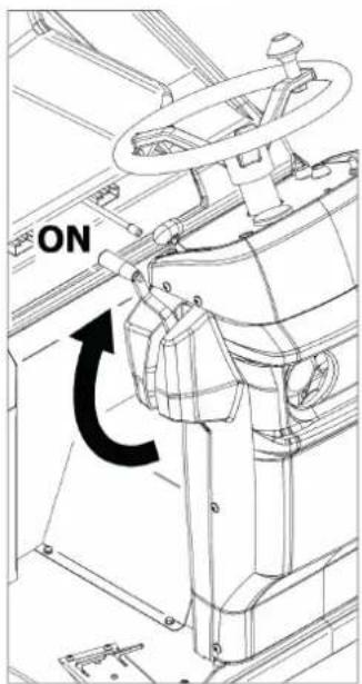
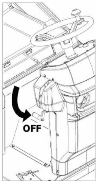
9.9. SIDEBRUSH
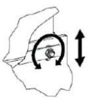
To activate the side brush, with the engine running or only with electrical services activated: raise the control lever (Item 7 PIC 11, PIC 19). Lower the lever to deactivate it (PIC 19).
NOTE: The lever manages both the descent and ascent movement, relative to the flooring, and its rotation. In the raised position it will always be stationary while it will begin to rotate when descending.
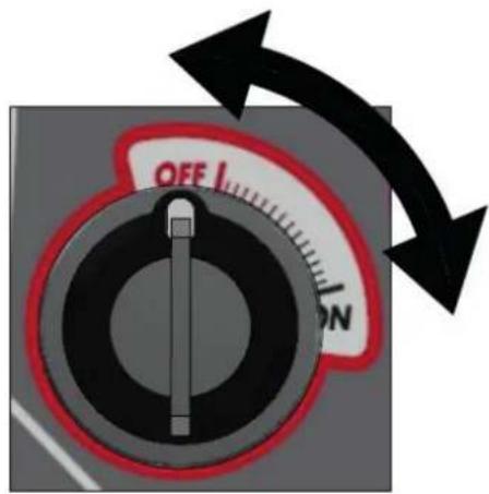
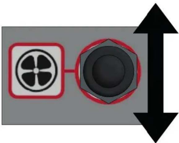
9.10. SUCTION
To activate or deactivate the suction, turn the relative switch (Item 9 PIC 11) (PIC 20).

The suction must be turned off before shaking the fi Iters.
9.11. FILTER SHAKER
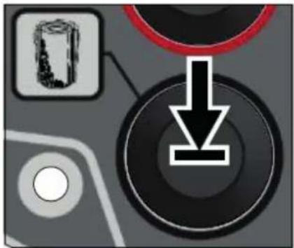
To activate the fi Iter shaker, with the engine started or only the electrical services activated, turn the relative switch (Item 10 PIC 11) by pressing it in an unstable position for the desired time and releasing it to deactivate it (PIC 21).
9.12. HORN SWITCH
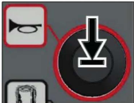
Pressing the button (Item 14 PIC 11) activates the horn, when the electrical services abled (PIC 22).
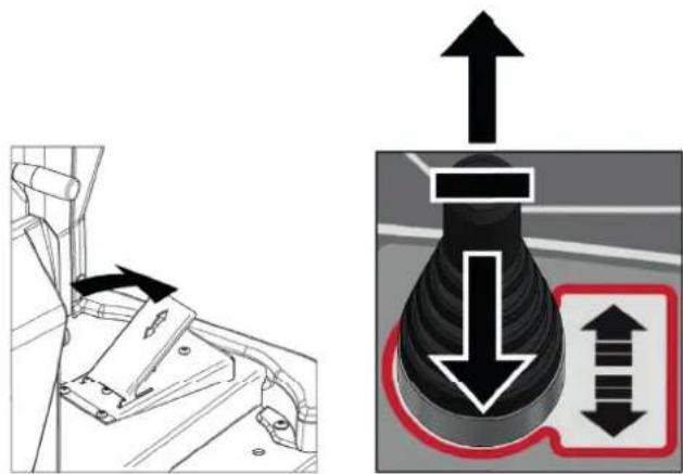
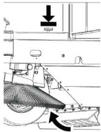
9.13. FLAP RAISE
To raise the front dust seal to collect larger waste, press the relevant pedal (Item 5 PIC 11) and hold it pressed for the desired time and releasing it to lower it to the ground.
9.14. EMPTYINGTHEWASTECONTAINER
9.14.1. MANUAL DISCHARGE VERSION
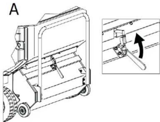
To proceed with emptying of the waste container (Item 3 PIC 3):
- Deactivate the central brush (§ 9.8);
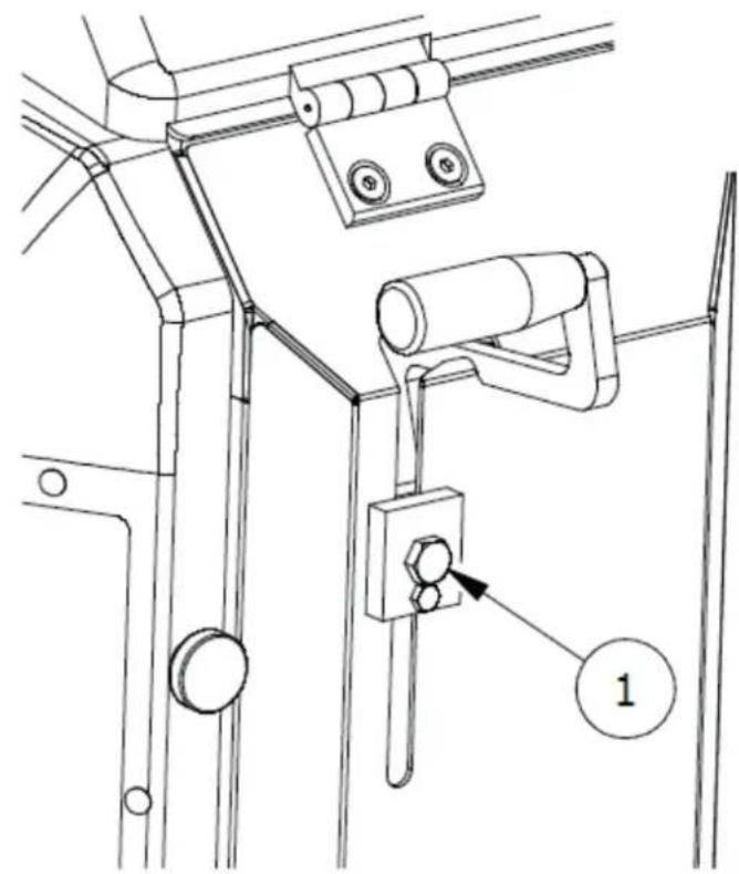
- Release the fi xing hook by lifting the relative lever (A, PIC 24);
- Remove the container from the sweeper by sliding it on the dedicated guides (B, PIC 24);
- Empty the plastic drawers (C, PIC 24)
To restore the waste container, follow the previous points in reverse order, being sure to insert the container so that its guides slide on the rollers (D, PIC 24).
9.14.2. VERSION WITH ASSISTED DISCHARGE (DSA, BIN-UP MODELS)
To empty the waste container, with the engine running:
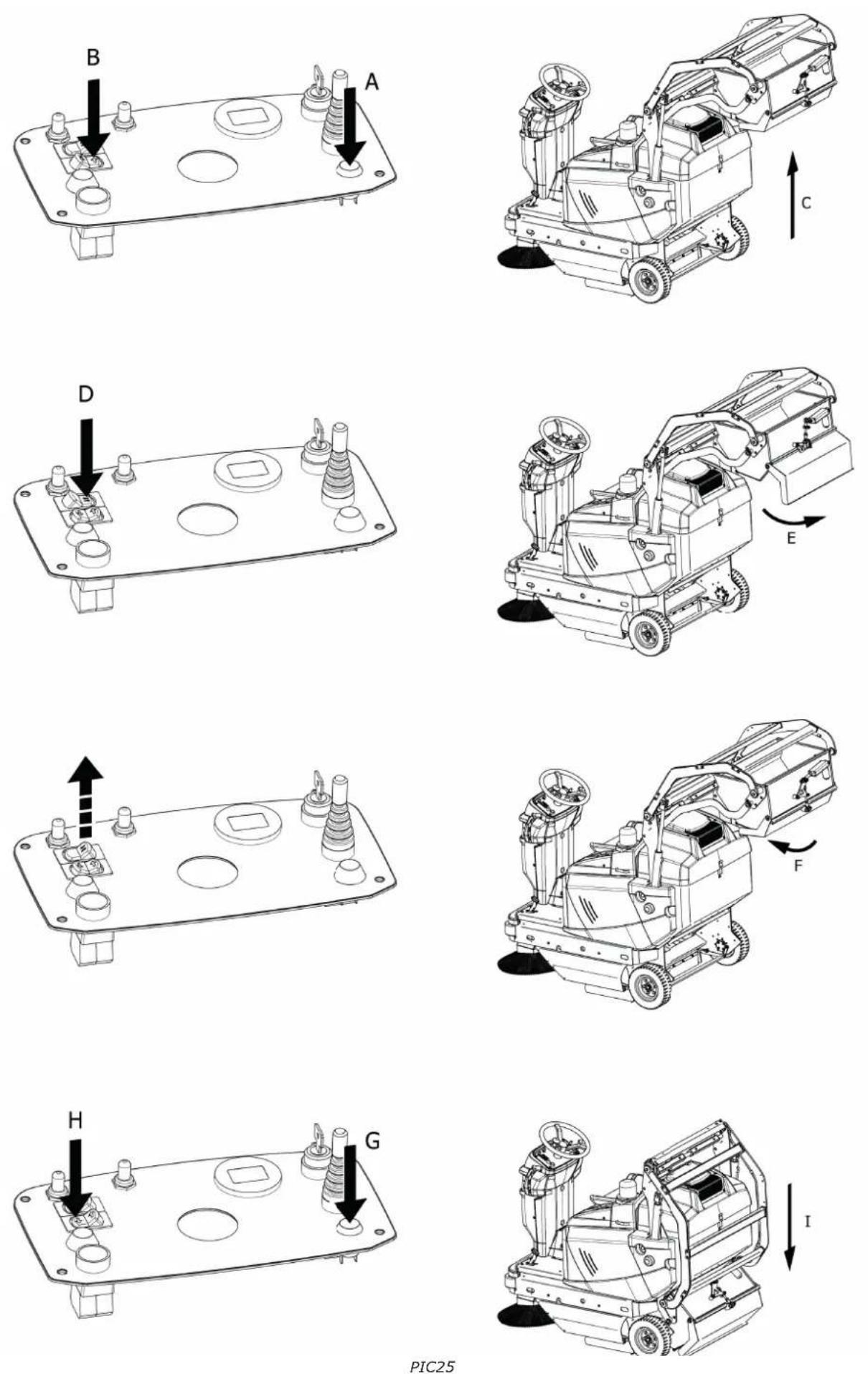
- Press the hydraulic consent button (Item 15 PIC 11) keeping it pressed PIC 25 for the entire duration of the operations (PIC 20)
- Raise the waste container using the waste container control (Item 11, PIC 11) by pressing it on the right side (B, PIC 25) and holding it in this position until the container reaches the desired position (C, PIC 25).
- Releasing the hydraulic consent button, open the container hatch while continuing to press the opening control switch (no. 12, PIC 25) in its only unstable position (D, PIC 25), so that the waste is released where desired (E, PIC 25). Next, release the switch to allow the hatch to close (F, PIC 25).
- Keeping the hydraulic consent button (G, PIC 25), pressed, lower the waste container through the waste container control by pressing it on the left side (H, PIC 25) and holding it in this position until the container reaches the initial position (I, PIC 25).
- Once the operations have been completed, release the hydraulic consent button.

MAKE SURE THAT THE MOTORISED BRUSH REMAINS STATIONARY FOR THE ENTIRE DURATION OF THE WASTE CONTAINER EMPTYING OPERATION.

IMPORTANT: be sure to keep the hydraulic consent button (No. 15 PIC 11) pressed whenever it acts on the button (No. 11 PIC 11) of waste container discharge. the assisted discharge system. Otherwise, the motorsweepers' hydraulic system could be damaged.
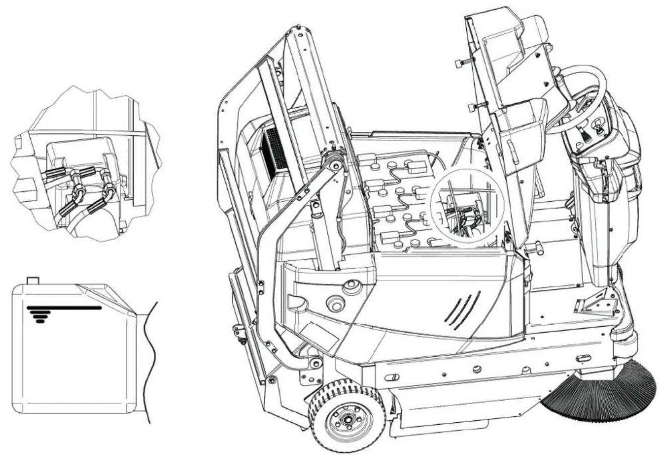
9.15. RECHARGING THE BATTERY (BATTERY-POWERED VERSION)
When the battery level is low, the battery must be recharged, proceeding as follows:
- Open the motor hood as shown in (PIC 13),
- Disconnect the plug (Item 2 PIC 8) as shown in (PIC 8);
- Connect the plug to the charger.
The connection to the charger is represented by:
ANDERSON type plug, 175A.
The characteristics of the batteries, if not supplied directly with the motorsweeper, are as follows:
6Volt DC, 320 Ah/5h (acid): nr. 4 pieces.
For which a charger with the following characteristics is recommended:
24Volt DC, 40A


ALWAYS CONSULT THE BATTERY AND CHARGER MANUAL FOR ANY FURTHER PROCEDURES TO BE FOLLOWED FOR CHARGING, WITH PARTICULAR REFERENCE TO THE PREVENTION AND PROTECTION MEASURES TO BE OBSERVED.
CHAPTER 10 - ADJUSTMENTS


BEFORE PROCEEDING, IT IS NECESSARY TO HAVE READ ALL THE PREVIOUS CHAPTERS.
10.1. TRAINING OF OPERATORS
There is no need for specific training of the operator with regard to the various phases of adjustment of the motorsweeper, except for the information contained in this manual.
10.2. ADJUSTING THE CENTRAL BRUSH ACTION

OPERATION TO BE PERFORMED WITH THE ELECTRICAL SERVICES DISABLED.
When the central brush (Item 2 PIC 3) is worn and, consequently, begins to decrease its efficiency, adjust its height, by the regulator (Item 8 PIC 11):
- first unscrew the screw(Item 1 PIC 26)
- slide the regulator onto the slot (Item 1 PIC 26) until the desired height is reached
- tighten the screw back to fix the adjustment.
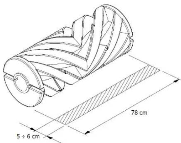
To verify that the central brush is properly adjusted, its "track" must be measured as follows:
a. After making the adjustments, activate the central brush and, without moving forward or backward, let it work at the same point for at least 10/15 seconds.
a. Lift the central brush and move the motorsweeper until the track that the central brush in rotation left is visible on the floor, as shown in PIC 27. Proceed with new adjustment if the track is different from the one shown.
10.3. ADJUSTING THE HEIGHT OF THE SIDE DUST SEALS


OPERATION TO BE PERFORMED WITH THE ELECTRICAL SERVICES DISABLED WITH GLOVES, SAFETY GOGGLES AND RESPIRATORY PROTECTION DEVICES.
If it is necessary to adjust the side dust seals (Item 3 PIC 5), for example after replacing them or for readjustment, proceed as follows:
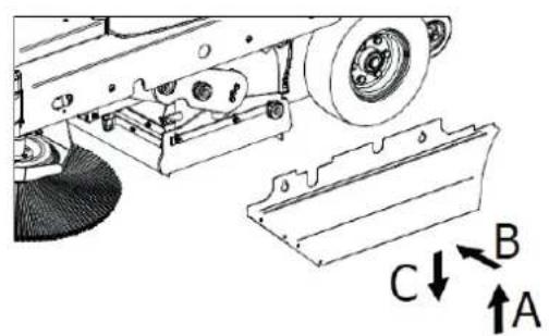
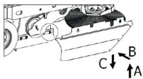
- disassemble the right and/or left side protection (Item 8 PIC 4); first lifting it upwards (A, PIC 28), then sliding it off the supports (B, PIC 28) and removing it completely (C, PIC 28);
- loosen the screws of the seal fastening strip (left and/or right) (PIC 28);
- move the seal downwards until it is 2mm from the ground;
- Once the desired adjustment has been reached, tighten the screws of the seal fastening strip PIC 28.
CHAPTER 11 - SAFETY RULES
11.1. GENERAL RESIDUAL RISKS

DEFINITION: The residual risks that cannot be eliminated are all those that, for various reasons, cannot be removed, but for each of which we report the indications to operate in the context of maximum safety.
- Risk of injury to the hands, body and eyes if the machine is used without all the safety protections correctly fitted and intact.
- Risk of injury to the hands from touching the side brush or the central brush for any reason during rotation. The brushes can only be touched with the engine off and with the aid of protective gloves to avoid being pricked or cut if in the bristles there were pointed splinters of debris in general.
- Risk of inhalation of harmful substances, abrasions to the hands due to emptying of the waste container without using protective gloves and mask to protect the respiratory tract.
- Risk of not being in control of the machine should it be used on slopes greater than those indicated in paragraphs 5.10 and 7.1, or of it not being properly stopped when left parked.
EN
- Risk of explosion or fire from refuelling with the engine on or with the engine off but not completely cold.
- Risk of serious burns from performing any maintenance with the engine on or engine off but not completely cold.
- Risk of inhalation of exhaust gas when used in an inadequately ventilated environment.
- Risk of noise generated by the machine;
- Risk of vibrations to both the hand-arm system and to the entire body.
11.2. GENERAL RISKS FOR ACID BATTERIES
- Before charging, check that the room is well ventilated or charge in rooms that may be used for this purpose.
- Do not smoke, do not approach with naked flames, do not use grinding wheels and welders; in any case, do not cause sparks near the batteries.
- Do not draw power from the battery with pliers, sockets and temporary contacts.
- Make sure that all connections (lugs, sockets, plugs, etc.) are always tight and in a good condition.
- Do not place metal tools on the battery.
- Keep the battery clean and dry using antistatic cloths if possible.
- Top up with distilled water whenever the electrolyte level drops to 5 - 10 mm from the splashguard.
- Avoid overcharging and keep the battery temperature below 45^ .
- Keep any centralised topping up systems in perfect working order, ensuring periodic maintenance is performed on them.
- Risk of electric shock and short circuit; for safety purposes, before carrying out any maintenance or repair on the battery (or on the machine), disconnect the +/- terminals from the battery poles.
- Risk of explosion during charging; this could occur when charging with an unsuitable battery charger (based on battery amps).
- During the battery charging operation, or in any case when the battery charger plug is inserted, it is forbidden to turn on the machine or to move it (even manually).
- In the event of accidental spills of liquid from the batteries due to any reason, mop up leaks with absorbent material using anti-acid gloves and clothing, safety glasses and respiratory protection devices, consulting the battery manual.
11.3. PROTECTIVE MEASURES
11.3.1. PERSONAL PROTECTION EQUIPMENT (PPE)
In addition to the above, to proceed safely during the operations of use, maintenance, adjustment, inspection and cleaning of the motorised brush, personal protection equipment (PPE) suitable for the type of risk that could occur will be necessary.
In particular, during the operations of use of the motorised brush, it will be necessary to:

Wear suitable PPE for hearing protection chosen based on both the level of noise generated ( § 5.10 ) and on the relative exposure time and considering any other external risks deriving from the use of the same such as:
- vehicular traffic and the presence of persons around the motorised brush during all its phases of use;
- failure to perceive acoustic alarm signals by the operator;
- presence of any ototoxic substances present in the surrounding environment.
- Wear suitable PPE to protect against the risk of hand-arm vibrations;
- Limit the time of continuous use of the motorised brush to protect the whole body system from the risk of vibrations.
In particular, for the maintenance operations referred to in this manual, the following will be necessary:

Safety gloves against mechanical risk;

Safety glasses;

Respiratory protective devices.
In case of accidental acid spills from the battery or if hazardous material has been accidentally collected, the following will be necessary:

Safety gloves against mechanical and chemical risks (e.g. neoprene gloves);

Safety glasses;

FFP3 or higher face mask;
Protective clothing against chemical risk.
For the cleaning operations of the motorsweeper it will also be necessary to use only suitable work clothes and ensure they are cleaned at the end of the work.


Refer to the documentation provided by the battery and charger manufacturer for further prevention and protection measures.
11.3.2. PROTECTIVE MEASURES FOR THE WASTE CONTAINER EMPTYING OPERATION
During the waste container emptying operations it will be necessary to respect the appropriate safety distances depending on the dimensions of the same (PIC 30).

CHECK THAT THERE ARE NO PERSONS LESS THAN 2 METERS FROM THE MOTORSWEEPER DURING THE WASTE CONTAINER EMPTYING OPERATIONS. ALSO CHECK THAT THERE IS ADEQUATE SPACE TO AVOID SHOCKS THAT COULD DAMAGE THE MOTORSWEEPER AND COMPROMISE ITS OPERATION.
FOR THE ASSISTED DISCHARGE VERSIONS (DSA, BIN-UP models): INSTALL BOTH SAFETY DEVICES OF THE WASTE CONTAINER, THE PROTECTIVE PIN AS SHOWN § 6.4.1.
TO PREVENT ACCIDENTAL CLOSURE OF THE WASTE CONTAINER WHEN IT IS BEING LIFTED.


FOR THE MANUAL DISCHARGE VERSIONS: IF THE WASTE PRESENT IN THE CONTAINER IS EXCESSIVELY HEAVY, PROCEED TO REMOVE IT WITH SUITABLE MEANS AND A LITTLE AT A TIME, WEARING SAFETY GLOVES SAFETY GLASSES AND RESPIRATORY PROTECTION DEVICES. ALTERNATIVELY SEEK THE HELP OF A SECOND PERSON.
CHAPTER 12 - STABILITY OF THE MACHINE
12.1. STABILITY DURING USE
The stability of the machine during travel and cleaning operations is mainly guaranteed by compliance with the maximum slope values ( § 5.10 and § 7.1 ) as well as by verification of the capacity of the work surface which must be such as to withstand the value of the weight of the motorsweeper indicated on the CE plate.
The operation of emptying of the waste container, and all the maintenance, adjustment, cleaning and inspection phases must take place on floors without slopes and such as to bear the value of the weight of the motorsweeper indicated on the CE plate.
To ensure the necessary stability during machine parking, it will be necessary to insert the parking brake as shown in § 9.6. If it is not possible to leave the machine stationary on flat surfaces, it is advisable to use dedicated wheel stop wedges.
The stability of the raised waste container for inspection, cleaning and maintenance operations is guaranteed by positioning the two safety support as described in § 6.4.1.
12.2. STABILITY DURING TRANSPORTATION
The motorsweeper must be transported and handled considering the weight of the motorsweeper indicated on the CE plate, and the values reported in § 5.10.
Lifting of the motorsweeper must take place as shown in para. CHAPTER 4 while for transportation it will be necessary to secure the machine. For this purpose, it is possible to use the relative fastening slots (PIC 31). Once positioned, it is necessary to insert the parking brake as shown in § 9.6 using, where appropriate and in addition, dedicated wheel stop wedges.
CHAPTER 13 - TRANSPORTATION, HANDLING AND DECOMMISSIONING
13.1. DECOMMISSIONING

OPERATION TO BE PERFORMED WITH THE ELECTRICAL SERVICES DISABLED.
The motorsweeper must be decommissioned in accordance with the following points:
- Disconnect the batteries by unplugging the charging plug as shown in PIC 8.
- For a good life of the unused battery, it is necessary to charge and possibly top up with distilled water every 30/40 days (acid batteries).
- Clean the dust fi Iters and the waste container.


Refer to the documentation provided by the Battery Manufacturer for further information on decommissioning the machine
13.2. PACKAGING, LIFTING AND TRANSPORTATION
In the event that the machine needs to be packed, it will be necessary to proceed with disassembly of the side brush/brushes as described in paragraph 15.5
Then lift the motorsweeper by placing it on the appropriate pallet using the necessary lifting devices, adapted to the weight of the motorsweeper shown on the plate, or ascent platforms. For lifting use the eyebolts (para. CHAPTER 4 Part. A, B, C PIC 2).
Observe what is indicated in the CHAPTER 4 regarding lifting of the machine, and in the paragraph 12.2 regarding its transportation.
CHAPTER 14 - EMERGENCY SITUATIONS
14.1. EMERGENCY SITUATIONS
In any emergency situation, the following may occur:
- inadvertently passing with the machine in motion over current cables on the floor, which then became twisted to the central or side brush,
- unusual noise is heard coming from inside the machine or engine,
- incandescent materials or fl ammable liquids, chemical materials in general, poisons, etc.
the following are necessary:
- If the engine is switched on, proceed to the emergency stop as described in paragraph § 9.7.
- Proceed to insert the parking brake as described in paragraph § 9.6
- Move away from the machine
Immediately call for help if other persons are involved.


Please refer to the documentation provided by the Battery and battery charger Manufacturer for further information on the procedures to be taken in the event of an emergency.
14.2. STARTING AFTER AN EMERGENCY SITUATION
Before proceeding to use the machine after an emergency situation has been resolved, an inspection of all the parts of the machine must be carried out (CHAPTER 5), with particular reference to the protections and safety devices.
It is only possible to resume normal use of the motorsweeper after these checks have been successful (all parts working and intact).
There are no rearming procedures.


Please refer to the documentation provided by the Battery Manufacturer for further information on the procedures to be taken in the event of an emergency.
CHAPTER 15 - MAINTENANCE
15.1. GENERAL SAFETY RULES


BEFORE PROCEEDING, IT IS NECESSARY TO HAVE READ ALL THE PREVIOUS CHAPTERS.

ALWAYS ENSURE THAT THE TWO SAFETY SUPPORT IS INSTALLED BEFORE WORKING BENEATH HOPPER (Part. 10 PIC 4) § 6.4.1.

ALL MAINTENANCE AND CLEANING OPERATIONS MUST BE CARRIED OUT WITH THE KEY DISCONNECTED AND THE ELECTRICAL SERVICES DISCONNECTED.

NEVER TOUCH THE BRUSHES WITH YOUR HANDS DURING ROTATION

CHECK THAT THERE ARE NO PERSONS UNRELATED TO THE CLEANING AND MAINTENANCE OPERATIONS LESS THAN 2 METERS FROM THE MOTORSWEEPER DURING THEIR ENTIRE DURATION.

TAKE THE NECESSARY MEASURES TO AVOID ACCIDENTAL AND INVOLUNTARY STARTING DURING ALL PHASES WHERE IT IS EXPECTED TO OPERATE WITH THE MOTOR OFF AND THE ELECTRICAL SERVICES DISCONNECTED.
There is no need for specific training of the operator with regard to the maintenance and cleaning of the motorsweeper, except for the information contained in this manual.
15.3. DUST SEALS


OPERATION TO BE PERFORMED WITH THE ELECTRICAL SERVICES DISABLED AND COLD WITH GLOVES, SAFETY GOGGLES AND RESPIRATORY PROTECTION DEVICES.
Every 90/120 hours of work, check the condition of the dust seals (Item 1 PIC 5) and replace if necessary. To replace the dust seals:
- Remove the right and/or left side protection (Item 8 PIC 4, Item 1 PIC 32) first lifting it upwards (A, PIC 32), then sliding it off the supports (B, PIC 32) and removing it completely (C, PIC 32);
- Loosen the screws of the seal listel fi xing listel (Item 3 PIC 32);
- Remove the worn seal and replace it with a new one (Item 2 PIC 32);
- Adjust the height from the ground as described in § 10.3;
- Retighten the screws of the seal fi xing plate (Item 3 PIC 32)
- Refit the right and/or left side protection (Item 1 PIC 32) following the steps in reverse order to those described for disassembly.
15.4. CENTRALBRUSH


OPERATION TO BE PERFORMED WITH THE ELECTRICAL SERVICES DISABLED AND COLD WITH GLOVES, SAFETY GOGGLES AND RESPIRATORY PROTECTION DEVICES. ONLY PROCEED WITH THE INSPECTION AFTER INSERTING THE TWO SAFETY SUPPORT (PARA. 6.4.1).
Every 60/90 hours of work or when required, check the good condition of the central brush (Item 2 PIC 3), in particular if it is assumed that it has inadvertently collected cords, wires, etc.
To proceed with the inspection of the central brush:
- lift the waste container and then turn off the engine and electrical services.
- install the two safety support (§ 6.4.1)
- proceed with the inspection.
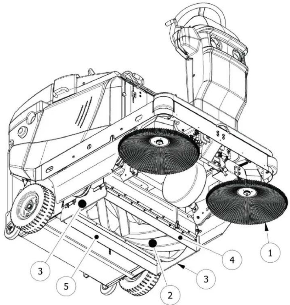
If it is necessary to replace the central brush:
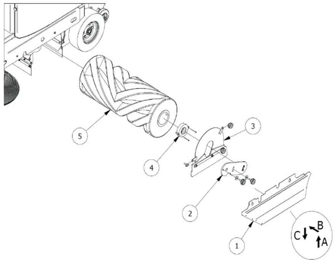
- Remove the left side protection (Item 8 PIC 4, Item 1 PIC 33) first lifting it upwards (A, PIC 33), then sliding it off the supports (B, PIC 33) and removing it completely (C, PIC 33).
- Remove the left arm of the sling bar (Item 2 PIC 33) by loosening the appropriate screws.
- Disassemble the brush door (Item 3 PIC 33).
- Remove the main brush hub (Item 4 PIC 33) by loosening the appropriate screws.
- Disassemble the brush (Item 5 PIC 33)
To complete the assembly, perform the operations described in reverse, being sure to respect the brush interconnections during reassembly.
Adjust the height of the new brush as described in paragraph 10.2.


MAKE SURE THAT THE TWO SAFETY SUPPORT HAS BEEN DISCONNECTED BEFORE LOWERING THE WASTE CONTAINER.
15.5. SIDEBRUSH


OPERATION TO BE PERFORMED WITH THE ELECTRICAL SERVICES DISABLED WITH GLOVES, SAFETY GOGGLES AND RESPIRATORY PROTECTION DEVICES.
Every 50/80 hours of work or when required, check the good condition of the side brush (Item 1 PIC 3 para. § 5.3), in particular if it is assumed that it has inadvertently collected cords, wires, etc.
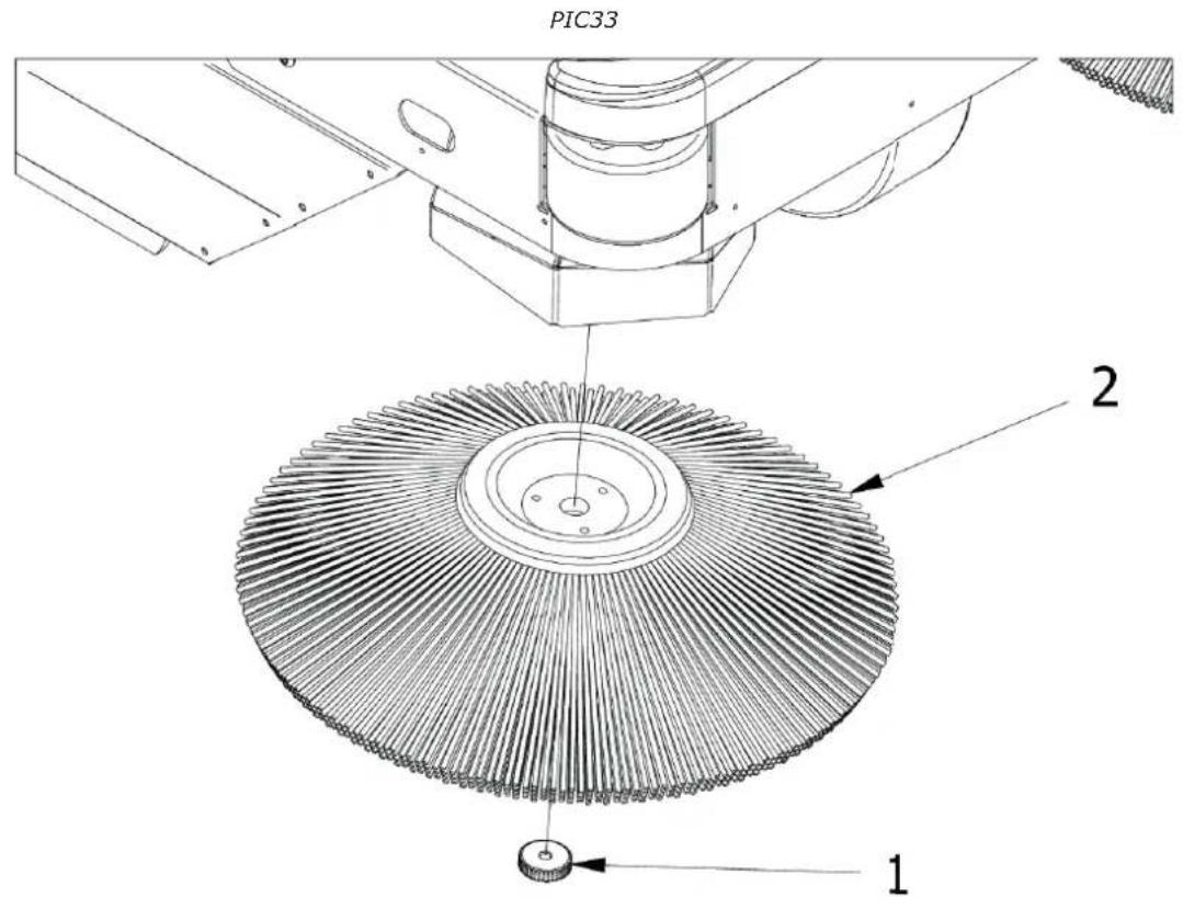
In the event that its replacement is necessary:
- Raise the side brush (para. § 9.9)
- Unscrew the ring nut Item 1 PIC 34 to detach the side brush (Item 2 PIC 34) from the plastic flange
- Replace the worn brush with the new one, inserting it on the flange and tightening the ring nut to lock it.
15.6. SPECIFIC MAINTENANCE FOR INTERNAL COMBUSTION ENGINES


Refer to the engine manual for further information on engine maintenance and related safety measures to be taken during operation.
Read the engine manual carefully, and:
1) Check the engine oil level every 20 hours of machine operation;
2) The first change of engine oil must take place after 50 hours of operation, add the quantity indicated in the engine manual; the recommended oil for temperate climates is 10W-30 multi-grade for petrol and diesel engines. When operating in areas with a non-temperate climate, identify the appropriate type of oil from the engine instruction manual. Use the dedicated drain to change the oil positioned under the engine sump.
3) Change the oil after every 90/100 hours of operation.
4) Clean the air filter every 25 operating hours, or earlier if necessary, and replace as necessary (see engine instruction manual).


TO CHECK OR REPLACE THE ENGINE OIL IT IS NECESSARY TO WEAR SAFETY GLOVES TO PROTECT AGAINST CHEMICAL AGENTS, POSSIBLY MADE OF NITRILE RUBBER. DO NOT DISPOSE OF USED OIL AS HOUSEHOLD WASTE AS IT IS HIGHLY POLLUTING. DISPOSE OF USED OIL IN ACCORDANCE WITH THE PROVISIONS OF THE LAW.
15.7. SPECIFIC MAINTENANCE FOR ACID BATTERIES


FOLLOW THE RULES AND PRECAUTIONS PROVIDED IN § 11.2. ALWAYS WEAR SAFETY GLASSES, SAFETY GLOVES, AND RESPIRATORY PROTECTIVE EQUIPMENT AND ANTI-ACID GLOVES AND CLOTHING.
- For a good life of the batteries, whether they are flat or tubular, never discharge them completely. FULLY DISCHARGED BATTERIES (EVEN NEW ONES) ARE NO LONGER RECHARGEABLE.
- Check often the level of solution of the battery and if necessary add only distilled water.
- Always carry out the charging cycle without interruption.
- DISPOSE OF USED BATTERIES FOLLOWING THE REGULATIONS IN FORCE.


Consult the documentation provided by the Battery Manufacturer for further information on their maintenance and related safety measures to be adopted during the operation.
15.8. CLEANING THE MACHINE
Clean the external parts of the machine using damp cloths or soft brushes.


OPERATION TO BE PERFORMED WITH THE ELECTRICAL SERVICES DISABLED WITH GLOVES, SAFETY GOGGLES AND RESPIRATORY PROTECTION DEVICES.

CLEANING OF ALL EXTERNAL PARTS OF THE MACHINE BY DIRECT WATER JET IS NOT PERMITTED.

DO NOT USE DETERGENTS OR CHEMICALS IN GENERAL THAT ARE TOO AGGRESSIVE, ABRASIVE POWDERS OR SIMILAR TO CLEAN THE CONTROL PANEL AND WHERE THERE ARE LABELS OR PRINTED PARTS IN GENERAL TO AVOID DAMAGING THEM, MAKING THEM INCOMPREHENSIBLE AND ILLEGIBLE.
15.9. CLEANING OF FILTERS


OPERATION TO BE PERFORMED WITH THE ELECTRICAL SERVICES DISABLED WITH GLOVES, SAFETY GOGGLES AND RESPIRATORY PROTECTION DEVICES.
15.9.1. BAGS FILTERS
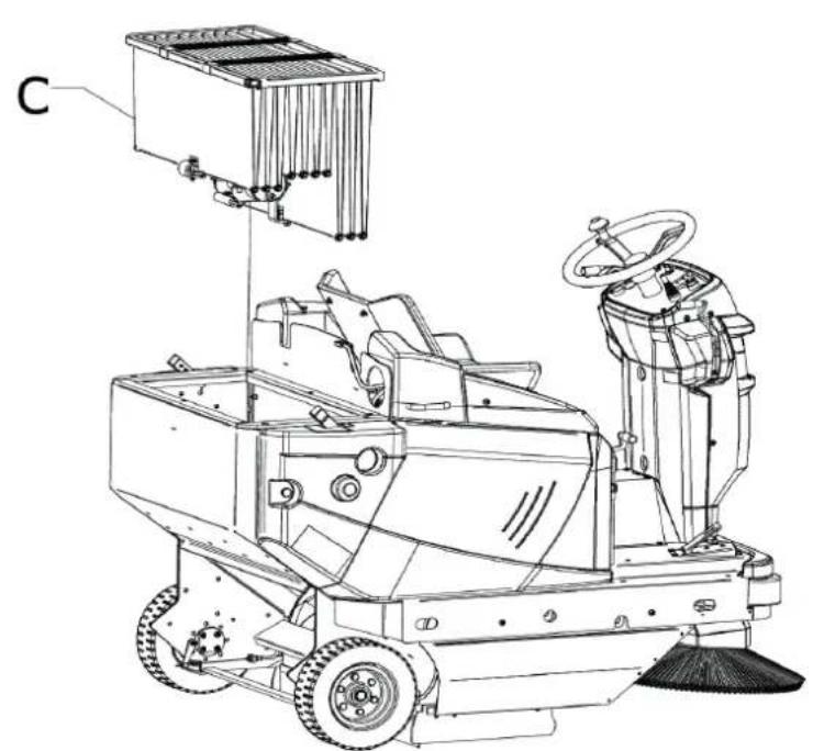
Every 60/100 hours of work, or when required, check the dust filter (Item 5 PIC 3 para. 5.7). For deep cleaning, it must be removed from its seat, as follows:
- Remove/Open the waste container as described in § 9.14;
- DSA VERSION: Install the two safety devices as described in § 6.4.1;
- Unplug the filter shaker (A PIC 35)
- Open the fi Iter cover (Item 1 PIC 4);
-
Unscrew the fi Iter support fi xing screws (Item B PIC 35)
-
lift the filter (Item 4 PIC 35) with a forklift truck, making sure that the internal measurement of the brackets is integral with the filter measurement (adjust the brackets to the correct distance between each other and lock them in place) or do so manually, with a minimum number of 2 persons. Then, keep it lifted from the ground with the aid of a forklift truck.
To clean it, fi rst shake it (not violently), then, to clean it thoroughly, with an air gun or similar blow from the outside inside. When reassembling, make sure that the black seal is always well supported and centred. At the end of the cleaning proceed to reassemble the fi lter by performing the operations described in reverse Make sure that the fi lter is always in a good condition and replace it if necessary.
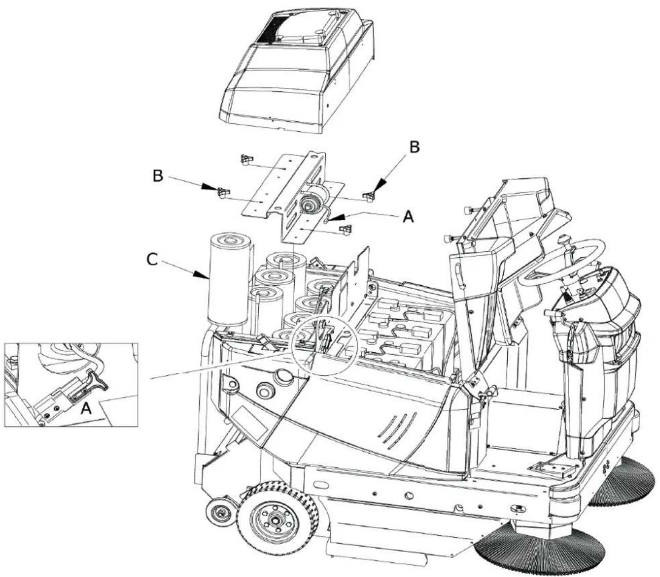
15.9.2. CARTRIDGE FILTERS
Every 200/300 hours of work, or when required, check the dust filter (Item 5 PIC 3 para. 5.7). For deep cleaning, it must be removed from its seat, as follows:
- Remove/Open the waste container as described in § 9.14;
- DSA VERSION: Install the two safety devices as described in § 6.4.1;
- Unplug the fi Iter shaker (A, PIC 36)
- Open the fi Iter cover (Item 1 PIC 4);
- Loosen the screws of the filter shaker support fasteners (B, PIC 36) and remove the support;
- extract the filter (C, PIC 36).
To clean it, first shake it (not violently) holding the perforated part downwards, then, to clean it thoroughly, with vacuum the inside with a vacuum cleaner. Or an air gun or similar blow from the outside inside. When reassembling, make sure that the black seal is always well supported and centred.
At the end of the cleaning proceed to reassemble the fi Iter by performing the operations described in reverse. Make sure that the fi Iter is always in a good condition and replace it if necessary
15.10. CLEANING THE WASTE CONTAINER


OPERATION TO BE PERFORMED WITH THE ELECTRICAL SERVICES DISABLED WITH GLOVES, SAFETY GOGGLES AND RESPIRATORY PROTECTION DEVICES. MAKE SURE THAT ACCESS TO PERSONS NOT INVOLVED IN THE OPERATIONS IS DENIED.
Every 50/60 hours of work, or when required, clean the waste container.
To proceed with the cleaning operations, it will first be necessary to open the waste container at the most convenient height, as described in § 9.14, and then turn off the motorsweeper so that cleaning can begin. Subsequently, it is advisable to inspect the parts around the central brush where the formation of scale or waste deposits is possible and, if necessary, proceed with removal. Simply lift the waste container (§ 9.14) and install the two safety devices (§ 6.4.1) to access the parts and to clean them.

IMPORTANT: It is highly recommended to clean the fi lter container without the use of water or to allow the motorsweeper to dry completely before resuming cleaning operations.
CHAPTER 16 - EXTRAORDINARYMAINTENANCE

EXTRAORDINARY MAINTENANCE ARE ALL OPERATIONS THAT HAVE NOT BEEN MENTIONED IN THIS BOOKLET; THEY MUST THEREFORE BE CARRIED OUT BY SPECIALIST ASSISTANCE PERSONNEL, APPOINTED FOR THIS PURPOSE (SEE BOOKLET COVER).
CHAPTER 17 - SPARE PARTS
For the replacement of machine parts, refer to the list of spare parts provided by the Manufacturer.
CHAPTER 18 - DISMANTLING AND DEMOLITION
If the machine will no longer be used, remove the batteries and dispose of them in accordance with
the eco-compatibility regulations as set forth in European standard 2013/56/EU or deposit them in an authorized collection centre.
To dispose of the machine, comply with the current laws where it is used:
- disconnect the machine from the mains and clean it after emptying any liquids;
- separate the machine into groups of homogeneous materials (plastics in accordance with the recycling symbol, metals, rubber, packing).
For parts containing different materials, contact the competent authorities; Each homogeneous group must be disposed of in accordance with recycling laws.
In addition, it is recommended to eliminate those parts of the machine that may be dangerous, especially for children
CHAPTER 19 - DEFECTS / CAUSES / SOLUTIONS
There are two fundamental defects:
- the machine creates dust during use,
- the machine leaves dirt on the ground.
There can be many causes, but with careful use and good routine maintenance they will not occur. The most common and frequent problems that can occur are listed in the following table.
| DEFECTS CAUSES SOLUTIONS | ||
| The machine creates dust. | Suction closed. Activate the suction | |
| Filter clogged. | Clean it, "shake" it with the appropriate tools and if necessary remove it and clean it thoroughly. | |
| Damaged filter Replace it. | ||
| Filter inserted incorrectly. | Fit it with the appropriate seal and make sure that it is well inserted and tightly in place with the appropriate fasteners. | |
| Continuous use of the side brush. | Use the side brush only for the cleaning of edges, profiles and corners. | |
| Damaged side seals. Adjust or replace them. | ||
| The machine leaves dirt on the ground. | The central brush is not adjusted properly or it has worn out. | Adjust the central brush, checking the "track". |
| You have picked up wires, cords, etc. | Remove them. | |
| Damaged side seals. Replace them. | ||
| Collection drawer full. Empty it. | ||
| The battery-powered machine does not perform at its best, is slow and does not clean well. | Low or not fully charged battery | Check the electrolyte level and proceed with a new complete charge cycle (see documentation provided by the Battery Manufacturer). |
| The charger is not the recommended one or is insufficient. | Use a suitable charger (§ 9.15). | |
CHAPTER 20 - WARRANTY
This machine is guaranteed against manufacturing or assembly defects for 12 months from the date of sale.
The warranty includes only and exclusively the replacement or repair of parts that are found to be defective. Any other requests will not be accepted.
Damage due to normal wear and tear, use other than that reported in this manual, damage caused by incorrect adjustments, technical interventions not performed correctly and acts of vandalism are not included.
CHAPTER 21 - EC DECLARATION OF CONFORMITY
The EC Declaration accompanies the motorsweeper together with this manual. Please refer to the relevant document for consultation.
SOMMAIRE....pag.
CHAPITRE 1 - BUTS/INTENTIONS 72
CHAPITRE 2 - LÉGENDE ..... 72
CHAPITRE 3 - RÈGLES GÉNÉRALES 73
CHAPITRE 4 - PRÉPARATION (DÉBALLAGE)....74
CHAPITRE 5 - DESCRIPTION DE LA MACHINE ..... 74
5.1. FONCTIONNEMENT ET PIÈCES PRINCIPALES .....74
5.2. PROTECTIONS ET DISPOSITIFS DE SÉCURITÉ 74
5.3. BROSSE LATÉRALE 75
5.4. BROSSE CENTRALE....75
5.5. JOINTS ANTI-POUSSIÈRE 75
5.6. SYSTÈME D'ASPIRATION....75
5.7. SYSTÈME DE FILTRATION 75
5.8. CONTENEUR DE DÉCHETS 75
5.9. BATTERIE 75
5.10. DONNÉES TECHNIQUES 76
CHAPITRE 6 - POSTE DE TRAVAIL ET COMMANDES ..... 77
6.1. POSITION DU POSTE DE TRAVAIL 77
CHAPITRE 19 - DÉFAUTS/CAUSES/SOLUTIONS ..... 92
CHAPITRE 20 - GARANTIE. 93
CHAPITRE 21 - DÉCLARATION DE CONFORMITÉ CE 93
CHAPITRE 1 - BUTS/INTENTIONS
AVANT D'UTILISER LA MACHINE, LIRE ATTENTIVEMENT CE MANUEL D'INSTRUCTIONS.
LA SOCIÉTÉ DÉCLINE TOUTE RESPONSABILITÉ POUR LES DOMMAGES AUX CHOSES ET/OU AUX PERSONNES RÉSULTANT DU NON-RESPECT DES NORMES ÉNUMÉRÉES DANS CE MANUEL OU D'UNE UTILISATION IRRÉGULIÈRE ET/OU INAPPROPRIÉE DE LA MACHINE.
LA MACHINE N'EST PAS DESTINÉE À ÊTRE UTILISÉE PAR DES PERSONNES (ENFANTS INCLUS) AYANT DES CAPACITÉS PHYSIQUES, SENSORIELLES ET PSYCHIQUES RÉDUITES OU QUI N'ONT PAS PLEINEMENT APPRIS ET COMPRIS TOUS LES CONTENUS DE CE MANUEL.
L'UTILISATION DE LA MACHINE DOIT ÊTRE SURVEILLÉE POUR ÉVITER SON UTILISATION PAR LES ENFANTS.
AFIN DE PRÉVENIR L'UTILISATION NON AUTORISÉE DE LA MACHINE, LA FORCE MOTRICE DOIT ÊTRE ÉTEINTE OU SÉCURISÉE, PAR EXEMPLE EN RETIRANT LA CLÉ DE CONTACT.
LA MACHINE LAISSÉE SANS SURVEILLANCE DOIT ÊTRE SÉCURISÉE CONTRE LES MOUVEMENTS INVOLONTAIRES.
LA MACHINE A ÉTÉ CONÇUE POUR UNE UTILISATION COMMERCIALE, PAR EXEMPLE DANS LES HÔTELS, LES HÔPITAUX, LES COMMERCES, LES MAGASINS, LES BUREAUX, LES LOCAUX LOUÉS ET LES GRANDS ESPACES EN GÉNÉRAL.
EN OUTRE, LA MACHINE :
- PEUT ÊTRE UTILISÉE À L'INTÉRIEUR SANS LIMITES ;
- NE DOIT PAS ÊTRE UTILISÉE OU TENUE À L'EXTÉRIEUR DANS DES CONDITIONS HUMIDES OU EXPOSÉE DIRECTEMENT À LA PLUIE ;
• DOIT ÊTRE STOCKÉE OBLIGATOIREMENT SOUS ABRI.
TOUS LES OUTILS NÉCESSAIRES À LA PROTECTION PERSONNELLE (GANTS, MASQUES, LUNETTES, VERRES BLANCS, CLÉS ET OUTILS) SERONT FOURNIS PAR L'UTILISATEUR.
POUR PLUS DE COMMODITÉ, CONSULTER L'INDEX DES SUJETS.
POUR TOUTE AUTRE CONSULTATION, TOUJOURS GARDER CE MANUEL AVEC SOI (EN CAS DE PERTE, DEMANDER IMMÉDIATEMENT UNE COPIE À VOTRE REVENDEUR).
LA SOCIÉTÉ SE RÉSERVE LE DROIT D'APPORTER DES MODIFICATIONS OU DES PERFECTIONNEMENTS AUX MACHINES DE SA PROPRE PRODUCTION, SANS OBLIGATION DE SA PART D'EN FAIRE BÉNÉFICIER LES MACHINES PRÉCÉDEMMENT VENDUES.
CHAPITRE 4 - PRÉPARATION(DÉBALLAGE)
POUR LES VERSIONS À DÉCHARGEMENT MANUEL : EN CAS DE POIDS EXCESSIF DES DÉCHETS PRÉSENTS DANS LE CONTENEUR, PROCÉDER À LEUR ÉLIMINATION AVEC DES MOYENS APPROPRIÉS ET UN PEU À LA FOIS, EN PORTANT DES LUNETTES DE SÉCURITÉ ET DES DISPOSITIFS DE PROTECTION DES VOIES RESPIRATOIRES. EN ALTERNATIVE DEMANDER L'AIDE D'UNE DEUXIÈME PERSONNE
CHAPITRE 12 - STABILITÉ DE LA MACHINE
12.1. STABILITÉ PENDANT L'UTILISATION
CHAPITRE 19 - DÉFAUTS/CAUSES/SOLUTIONS

- HS R 130 / BC HS R 130 ADM / BC ADM
- CHAPTER 1 - PURPOSES / INTENTIONS
- Always contact specialised personnel for extraordinary maintenance operations (par. CHAPTER 16).
- CHAPTER 2 - LEGEND
- CHAPTER 3 - GENERAL RULES
- BEFORE USING THE MACHINE READ THIS INSTRUCTION MANUAL CAREFULLY.
- CHAPTER 4 - PREPARATION(UNPACKING)
- CHAPTER 5 - MACHINEDESCRIPTION
- OPERATION AND MAIN PARTS
- The machine operates through a battery motor.
- SAFETY PROTECTIONS AND DEVICES
- SIDE BRUSH
- CENTRALBRUSH
- DUST SEALS
- SUCTION SYSTEM
- FILTERING SYSTEM
- WASTE CONTAINER
- BATTERY
- CHAPTER 6 - WORK STATION AND CONTROLS
- WORKPLACEPOSITION
- OPERATOR COMFORT
- CONTROL DEVICES
- POSITION OF THE CONTROLS AND DESCRIPTION
- STARTER KEY
- THROTTLE. ACCELERATOR PEDAL
- GEAR SELECTOR (FORWARD, BACKWARD)
- BRAKE PEDAL
- FLAP RAISE
- CENTRAL BRUSH CONTROL
- CENTRAL BRUSH ACTION REGULATOR
- SUCTION SWITCH
- FILTER SHAKER SWITCH
- WASTE CONTAINER CONTROL (DSA VERSION ONLY)
- WASTE CONTAINER OPENING CONTROL (DSA VERSION ONLY)
- HOUR METER
- HORN SWITCH
- HYDRAULIC CONSENT SWITCH (DSA VERSION ONLY)
- WORK LIGHTS SWITCH
- EMERGENCY BUTTON
- PARKING BRAKE
- USE OF SAFETY PROTECTIONS AND DEVICES
- WASTE CONTAINER SAFETY DEVICES POSITIONING
- ENGINE HOOD AND FILTER CARTER
- CHAPTER 7 - PERMITTED AND NON-PERMITTED CONDITIONS OF USE
- PERMITTED CONDITIONS OF USE
- NON-PERMITTED CONDITIONS OF USE
- CHAPTER 8 - COMMISSIONING
- CHECKS BEFORE FIRST START-UP
- DSA, BIN-UP VERSIONS:
- FIRST START-UP
- CHAPTER 9 - USING THE MACHINE
- CORRECT USE AND TIPS
- OPERATIONAL START-UP
- TRAVEL
- OPERATIONALSHUTDOWN
- PARKING
- EMERGENCYSTOP
- CENTRALBRUSH
- SIDEBRUSH
- SUCTION
- FILTER SHAKER
- HORN SWITCH
- FLAP RAISE
- EMPTYINGTHEWASTECONTAINER
- MANUAL DISCHARGE VERSION
- VERSION WITH ASSISTED DISCHARGE (DSA, BIN-UP MODELS)
- RECHARGING THE BATTERY (BATTERY-POWERED VERSION)
- CHAPTER 10 - ADJUSTMENTS
- TRAINING OF OPERATORS
- ADJUSTING THE CENTRAL BRUSH ACTION
- OPERATION TO BE PERFORMED WITH THE ELECTRICAL SERVICES DISABLED.
- ADJUSTING THE HEIGHT OF THE SIDE DUST SEALS
- CHAPTER 11 - SAFETY RULES
- GENERAL RESIDUAL RISKS
- EN
- GENERAL RISKS FOR ACID BATTERIES
- PROTECTIVE MEASURES
- PERSONAL PROTECTION EQUIPMENT (PPE)
- PROTECTIVE MEASURES FOR THE WASTE CONTAINER EMPTYING OPERATION
- CHAPTER 12 - STABILITY OF THE MACHINE
- STABILITY DURING USE
- STABILITY DURING TRANSPORTATION
- CHAPTER 13 - TRANSPORTATION, HANDLING AND DECOMMISSIONING
- DECOMMISSIONING
- Refer to the documentation provided by the Battery Manufacturer for further information on decommissioning the machine
- PACKAGING, LIFTING AND TRANSPORTATION
- CHAPTER 14 - EMERGENCY SITUATIONS
- EMERGENCY SITUATIONS
- the following are necessary:
- Immediately call for help if other persons are involved.
- STARTING AFTER AN EMERGENCY SITUATION
- CHAPTER 15 - MAINTENANCE
- GENERAL SAFETY RULES
- DUST SEALS
- OPERATION TO BE PERFORMED WITH THE ELECTRICAL SERVICES DISABLED AND COLD WITH GLOVES, SAFETY GOGGLES AND RESPIRATORY PROTECTION DEVICES.
- CENTRALBRUSH
- OPERATION TO BE PERFORMED WITH THE ELECTRICAL SERVICES DISABLED AND COLD WITH GLOVES, SAFETY GOGGLES AND RESPIRATORY PROTECTION DEVICES. ONLY PROCEED WITH THE INSPECTION AFTER INSERTING THE TWO SAFETY SUPPORT (PARA. 6.4.1).
- MAKE SURE THAT THE TWO SAFETY SUPPORT HAS BEEN DISCONNECTED BEFORE LOWERING THE WASTE CONTAINER.
- SIDEBRUSH
- OPERATION TO BE PERFORMED WITH THE ELECTRICAL SERVICES DISABLED WITH GLOVES, SAFETY GOGGLES AND RESPIRATORY PROTECTION DEVICES.
- SPECIFIC MAINTENANCE FOR INTERNAL COMBUSTION ENGINES
- SPECIFIC MAINTENANCE FOR ACID BATTERIES
- CLEANING THE MACHINE
- CLEANING OF FILTERS
- BAGS FILTERS
- CARTRIDGE FILTERS
- CLEANING THE WASTE CONTAINER
- CHAPTER 16 - EXTRAORDINARYMAINTENANCE
- CHAPTER 17 - SPARE PARTS
- CHAPTER 18 - DISMANTLING AND DEMOLITION
- CHAPTER 19 - DEFECTS / CAUSES / SOLUTIONS
- CHAPTER 20 - WARRANTY
- CHAPTER 21 - EC DECLARATION OF CONFORMITY
- CHAPITRE 19 - DÉFAUTS/CAUSES/SOLUTIONS ..... 92
- CHAPITRE 20 - GARANTIE. 93
- CHAPITRE 21 - DÉCLARATION DE CONFORMITÉ CE 93
- CHAPITRE 1 - BUTS/INTENTIONS
- AVANT D'UTILISER LA MACHINE, LIRE ATTENTIVEMENT CE MANUEL D'INSTRUCTIONS.
- CHAPITRE 4 - PRÉPARATION(DÉBALLAGE)
- CHAPITRE 12 - STABILITÉ DE LA MACHINE
- STABILITÉ PENDANT L'UTILISATION
- CHAPITRE 19 - DÉFAUTS/CAUSES/SOLUTIONS
Brand : Ghibli & Wirbel
Model : HS R 130
Category : Sweeper