
TD283 - Battery monitor DOMETIC - Free user manual and instructions
Find the device manual for free TD283 DOMETIC in PDF.

| Product type | Battery monitor with 2.83" TFT color touch screen |
| Brand and model | Dometic TD283 |
| Dimensions | 79 × 100 × 12 mm |
| Weight | 70 g |
| Power consumption | 54 mA (max backlight), 15 mA (standby) |
| Power supply | 12 V DC (via N-BUS communication cable) |
| Main functions | Display of state of charge (SoC) in % and circle, voltage (V), current (A) of the internal battery; display of charger, solar controller, inverter data; 3-week solar history; battery temperature alarm; Bluetooth enable/disable; standby and N-BUS network shutdown |
| Compatibility | N-BUS network (compatible Dometic devices), TEMPRA batteries (TLB 100(F)-150(F)), chargers, solar controllers, inverters; Dometic SunControl app (via Bluetooth) |
| Interfaces | Touch screen, N-BUS communication cable connection, Bluetooth (for integrated modules) |
| Available languages | Italian, English, German, French, Spanish, Dutch |
| Operating temperature | -10 to 70 °C |
| Installation | Wall mounting with mounting plate and screws (Ø 3 mm), cable passage Ø 8 mm. Installation by qualified personnel recommended |
| Safety | Do not open or repair yourself; use only recommended accessories; avoid short circuit and humidity; follow the instructions in the manual |
| Maintenance and cleaning | Clean the touch screen with a dry (or slightly damp) microfiber cloth; do not use abrasive products, ammonia, or alcohol; do not spray liquid directly |
| Spare parts and repairability | Accessories: N-BUS connection cables (ref. 9620008182, 9620008462, 9620008275). Repairs only by qualified personnel; legal warranty |
| Certifications | CE, UK, CA |
| Package contents | Screen cover, mounting plate, screws (4), communication cable (1) |
Frequently Asked Questions - TD283 DOMETIC
User questions about TD283 DOMETIC
0 question about this device. Answer the ones you know or ask your own.
Ask a new question about this device
Download the instructions for your Battery monitor in PDF format for free! Find your manual TD283 - DOMETIC and take your electronic device back in hand. On this page are published all the documents necessary for the use of your device. TD283 by DOMETIC.
USER MANUAL TD283 DOMETIC
natural_image
Isometric line drawing of a rectangular panel with a recessed side and a central slanted cover (no text or symbols)TD283
EN
Display
Installation and Operating manual....3
DE
Display
© 2024 Dometic Group. The visual appearance of the contents of this manual is protected by copyright and design law. The underlying technical design and the products contained herein may be protected by design, patent or pending patent. The trademarks mentioned in this manual belong to Dometic Sweden AB. All rights are reserved.
English
1 Important notes
Please read these instructions carefully and follow all instructions, guidelines, and warnings included in this product manual in order to ensure that you install, use, and maintain the product properly at all times. These instructions MUST stay with this product.
By using the product, you hereby confirm that you have read all instructions, guidelines, and warnings carefully and that you understand and agree to abide by the terms and conditions as set forth herein. You agree to use this product only for the intended purpose and application and in accordance with the instructions, guidelines, and warnings as set forth in this product manual as well as in accordance with all applicable laws and regulations. A failure to read and follow the instructions and warnings set forth herein may result in an injury to yourself and others, damage to your product or damage to other property in the vicinity. This product manual, including the instructions, guidelines, and warnings, and related documentation, may be subject to changes and updates. For up-to-date product information, please visit documents.dometic.com.
2 Explanation of symbols

CAUTION!
Indicates a hazardous situation that, if not avoided, could result in minor or moderate injury.

NOTICE!
Indicates a situation that, if not avoided, can result in property damage.

NOTE Supplementary information for operating the product.
3 Safety instructions
General safety

CAUTION! Electrocution hazard
- Do not operate the device if it is visibly damaged.
- Have this device repaired by qualified personnel only. Improper repairs can lead to considerable hazards.
- Do not disconnect any cables when the device is still in use.
- Only use accessories that are recommended by the manufacturer.
- Do not modify or adapt any of the components in any way.

CAUTION! Health hazard
- Electrical devices are not toys. Always keep and use the device out of the reach of very young children.
- Children must be supervised to ensure that they do not play with the device.
- Cleaning and user maintenance shall not be made by children without supervision.

NOTICE! Damage hazard
- Ensure that other objects cannot cause a short circuit at the contacts of the device.
- Do not use the device in wet conditions or submerge in any liquid. Store in a dry place.
Installing the device safely

CAUTION! Electrocution hazard
- Installation and removal of the device may only be carried out by qualified personnel.
- Crushed cables can lead to moderate injury.
Lay the cables so that they cannot be damaged by the doors or the hood.
Use ductwork or cable ducts if it is necessary to lay cables through metal panels or other panels with sharp edges.
Do not lay cables so that they are loose or heavily kinked. Do not pull on the cables.

CAUTION! Risk of injury
When positioning the device, ensure that all cables are suitably secured to avoid any form of trip hazard.

NOTICE! Damage hazard
- Do not place the device near heat sources (heaters, direct sunlight, gas ovens, etc.).
- Set up the device in a dry location where it is protected against splashing water.
- Before start-up, check that the voltage specification on the data plate is the same as that of the power supply.

NOTE Use N-BUS connection cables when connecting N-BUS-capable devices.
4 Scope of delivery
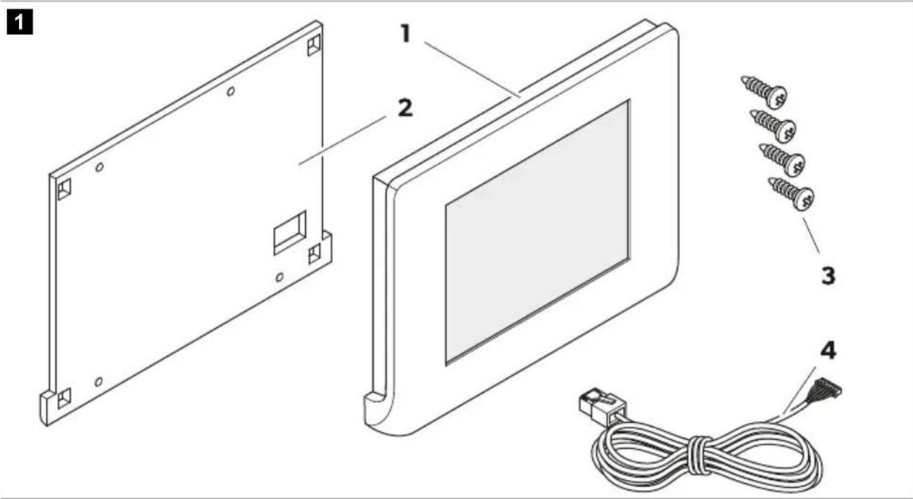
Pos. Designation Quantity
| 1 Display cover 1 |
| 2 Mounting plate 1 |
| 3 Screws 4 |
| 4 Communication cable 1 |
5 Accessories
Designation Ref.no.
| Dometic NDS BC10M (N-BUS connection cable, 10 m) 9620008182 |
| Dometic NDS BC06M (N-BUS connection cable, 6 m) 9620008462 |
| Dometic NDS BC03M (N-BUS connection cable, 3 m) 9620008275 |
6 Intended use
The display is intended as a battery monitor for displaying and monitoring the current state of charge, voltage and current of N-BUS-capable vehicle batteries and for controlling N-BUS-capable devices in the network.
The display is suitable for:
• Installation in recreational vehicles, boats and trucks
- Connection to vehicle battery TEMPRA (TLB 100(F)-150(F))
- Connection to battery chargers, solar charge controllers and inverters
EN Dometic TD283
• Stationary or mobile use
- Indoor use
The display is not suitable for:
- Mains operation
- Outdoor use
This product is only suitable for the intended purpose and application in accordance with these instructions.
This manual provides information that is necessary for proper installation and/or operation of the product. Poor installation and/or improper operating or maintenance will result in unsatisfactory performance and a possible failure.
The manufacturer accepts no liability for any injury or damage to the product resulting from:
- Incorrect installation, assembly or connection, including excess voltage
- Incorrect maintenance or use of spare parts other than original spare parts provided by the manufacturer
• Alterations to the product without express permission from the manufacturer - Use for purposes other than those described in this manual
Dometic reserves the right to change product appearance and product specifications.
7 Technical description
The display is equipped with a touchscreen and can be operated with a voltage of 12 V.
The display is compatible with Dometic apps for mobile devices, e.g. SunControl app (only if a Bluetooth device is connected to the N-BUS network).
Components
2
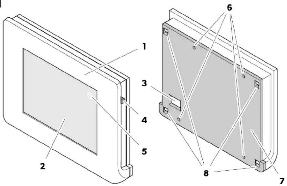
Pos. Description
| 1 Display cover |
| 2 Touchscreen |
| 3 Communication cable connection |
| 4 Power switch |
| 5 Power button |
| 6 Mounting holes |
| 7 Mounting plate |
| 8 Fixing holes |
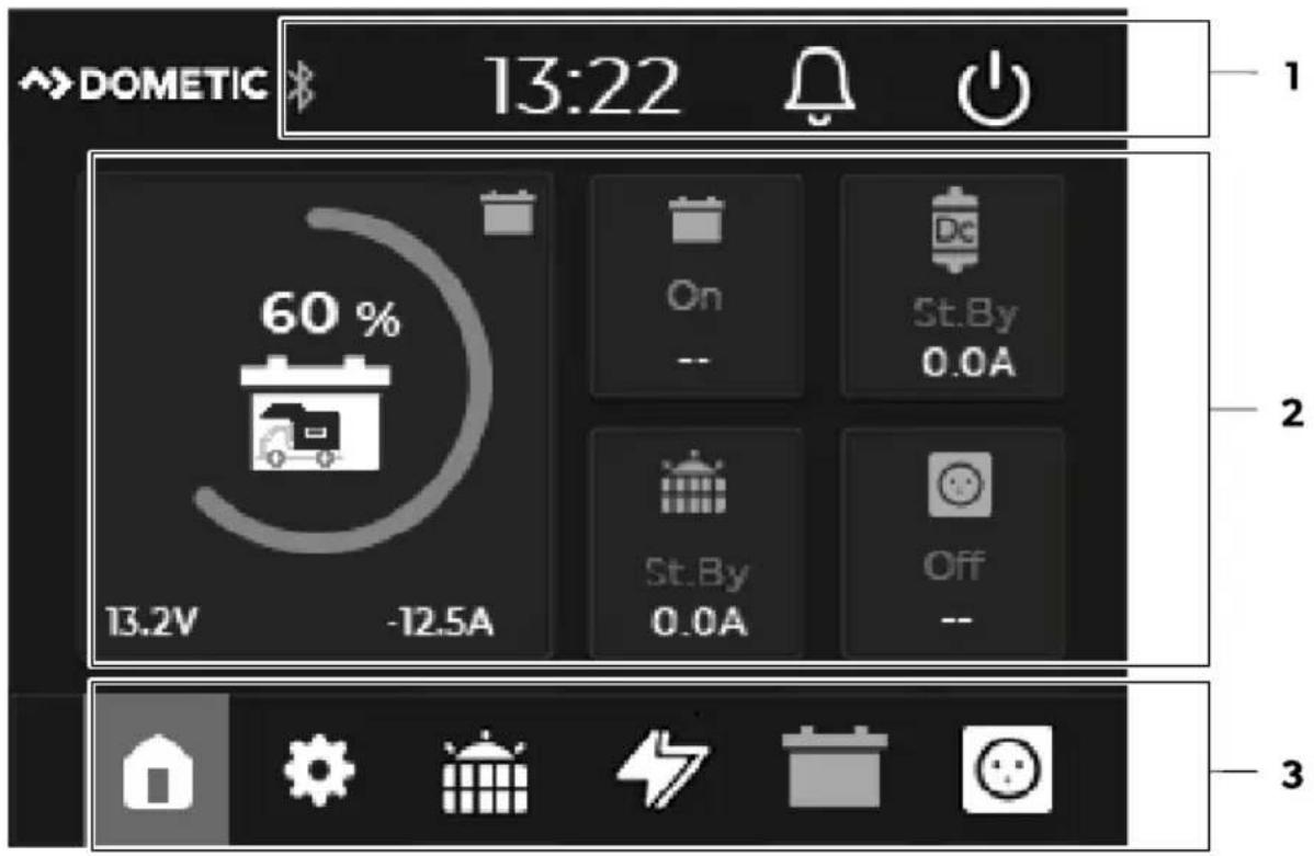
Touchscreen
3

Pos. Component Description
| 1 Status bar | Shows active functions (Bluetooth) of connected N-BUS devices, time and notifications (error messages). | |
 | Bluetooth function of connected N-BUS devicesLights up yellow as soon as the Bluetooth function of connected N-BUS devices is activated. | |
 | Error indicationA red dot on the bell indicates that an error has been detected. The error messages can be called up by pressing the bell. | |
 | Power buttonSwitches off the display and all N-BUS-capable devices in the network. | |
| 2 Menu display | Dynamic screen, shows the most important data of the devices connected to the N-BUS in the selected menu.As start screen, the main menu is displayed. | |
 | A flash on the battery symbol indicates that the house battery is being charged. | |
Pos. Component Description
Via the menu bar, the main and settings menu as well as the menus for connected devices can be selected.
The menu for currently connected devices is shown in white, the menu for active devices (status "On") is shown in yellow and the menu for devices that are not connected is grayed out. Grayed out menus are not selectable.
3 Menu bar

Main menu

Settings menu

Solar charge controller menu

Battery charger menu

House battery menu

Inverter menu
Main menu
4
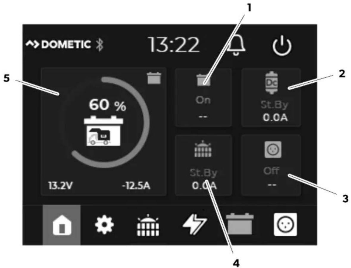
Pos. Description
| 1 | Status of the house battery (On/Off)Voltage (in V) of the house battery |
| 2 | Status of the battery charger (Standby/Bulk/Absorption/Float/Off)Power supply (in A) from the battery charger |
| 3 | Status of the inverter (On/Off)Output voltage (in V) of the inverter |
| 4 | Status of the solar charge controller (Standby/MPPT/Absorption/Float/Off)Power supply (in A) from the solar charge controller |
| 5 | State of charge (SoC) of the house battery (circle diagram in 25 %* steps) with current values for voltage (in V) and current (in A)* Note: If a TEMPRA battery (TLB 100(F)-150(F)) is connected in the N-BUS network, the SoC is displayed in 5 % steps |
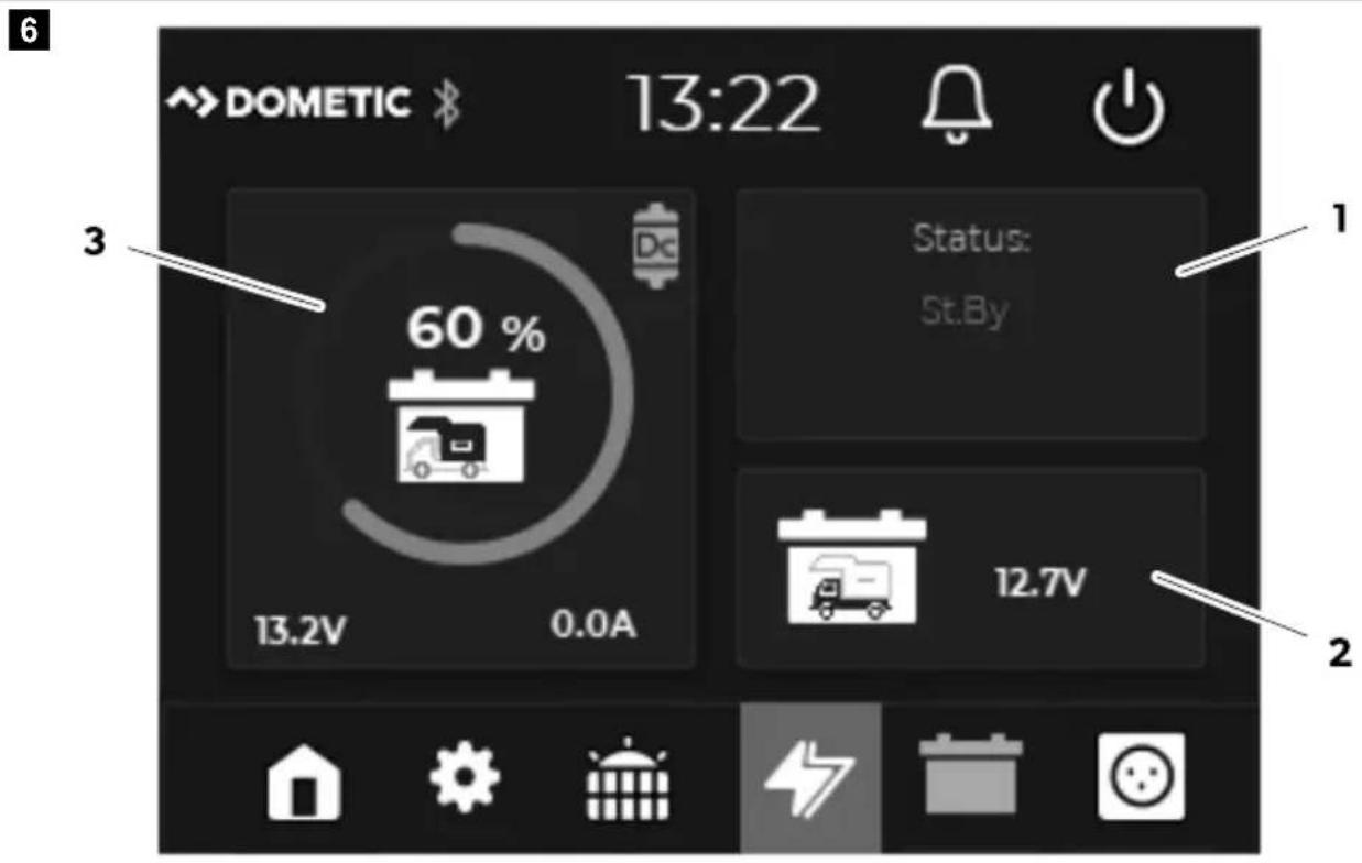
Solar charge controller menu
5

Pos. Description
| 1 Current value for voltage (in V) of the starting battery | |
| 2 Open Hist. for an overview of the solar energy delivered over the last 3 weeks. | |
| 3 Daily output (in Wh) of connected solar panels | |
| 4 Status of the solar charge controller (Standby/MPPT/Absorption/Float/Off) | |
| 5 | State of charge (SoC) of the house battery (circle diagram in 25 %* steps) with current values for voltage (in V) and current (in A)* Note: If a TEMPRA battery (TLB 100(F)-150(F)) is connected in the N-BUS network, the SoC is displayed in 5 % steps |
 | (No number is displayed) One solar module input connected |
 | Two solar module inputs connected and active |
Battery charger menu
Pos. Description
| 1 Status of the battery charger (Standby/Bulk/Absorption/Float/Off) | |
| 2 Voltage (in V) of the starting battery | |
| 3 | State of charge (SoC) of the house battery (circle diagram in 25 %* steps) with current values for voltage (in V) and current (in A)* Note: If a TEMPRA battery (TLB 100(F)-150(F)) is connected in the N-BUS network, the SoC is displayed in 5 % steps |
House battery menu
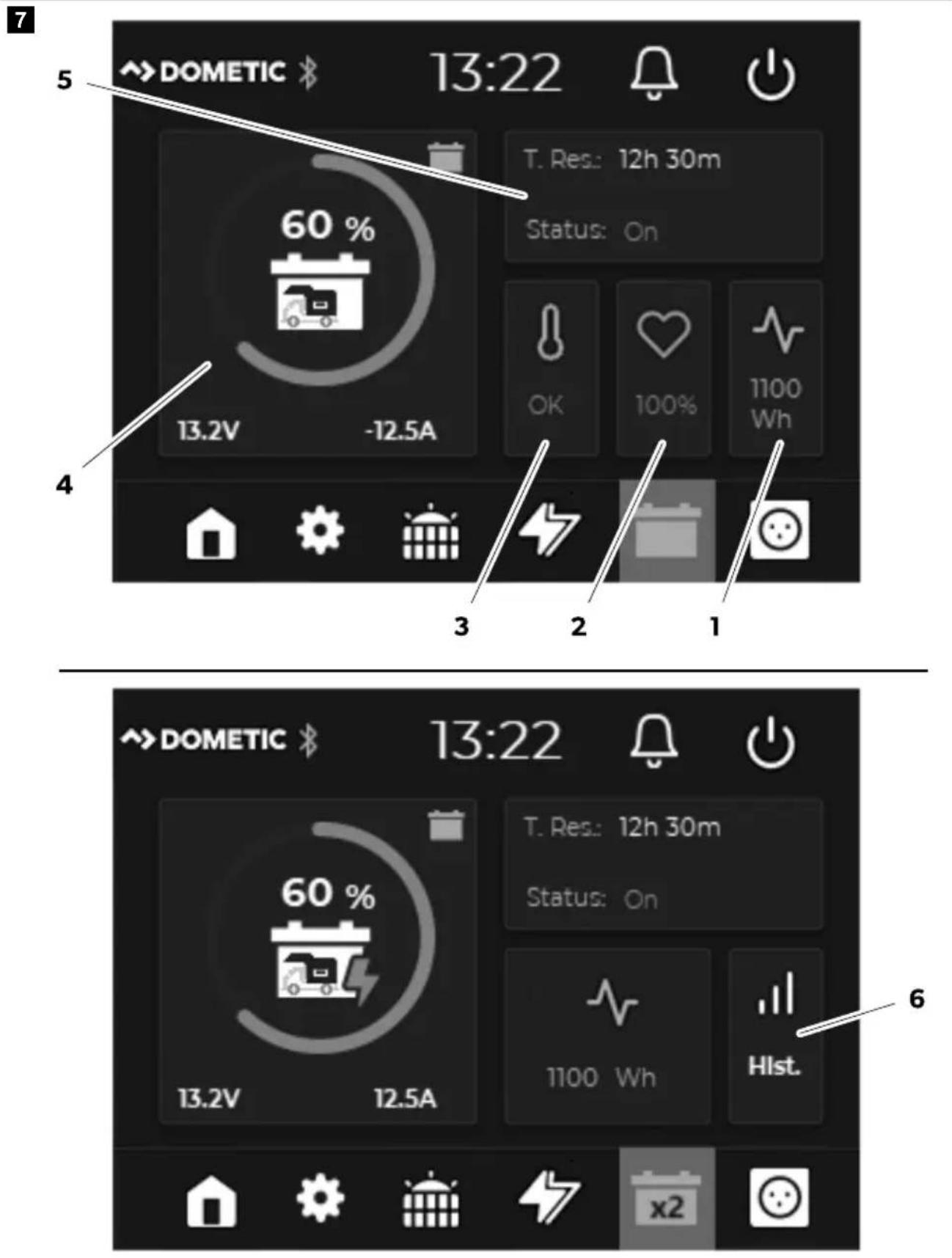
Pos. Description
1 Battery capacity in Wh
2 Battery condition (State of Health (SoH) in %)
3
Analysis of the battery temperature
- OK: Temperature within the permitted range
• Hi: High temperature - Low: Low temperature
Alarm if the temperature moves into a critical range
4 State of charge of the house battery (in %) with current values for voltage (in V) and current (in A)
5 Status of the house battery (On/Off) and time to full charge/discharge
6
If more than one battery is connected in the N-BUS network:
Open Hist. for an overview of the individual battery condition and battery temperature for up to 4 batteries in the network.

More than one battery is connected to the N-BUS network
Inverter menu
8
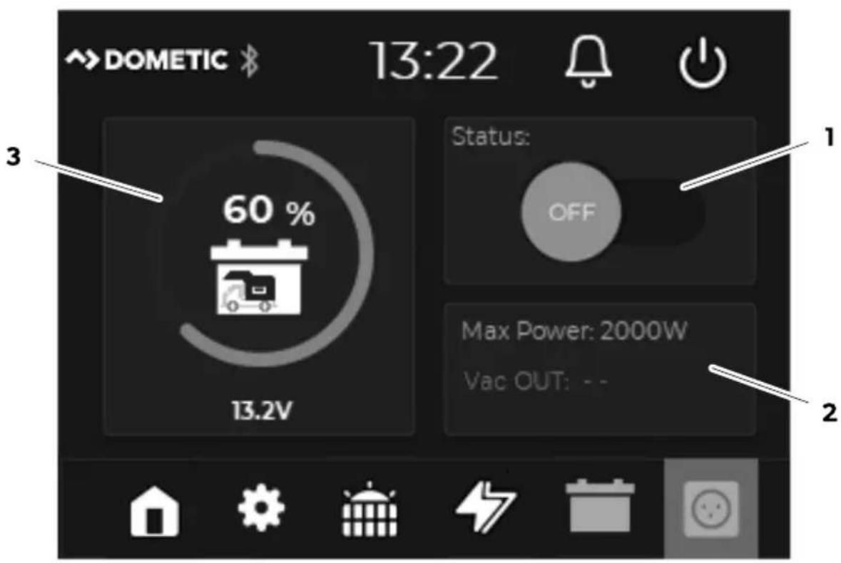
Pos. Description
1 Status of the inverter (On/Off)
Pos. Description
2 Maximum surge power (in W) and current output voltage
3 State of charge of the house battery (in %) with current value for voltage (in V)
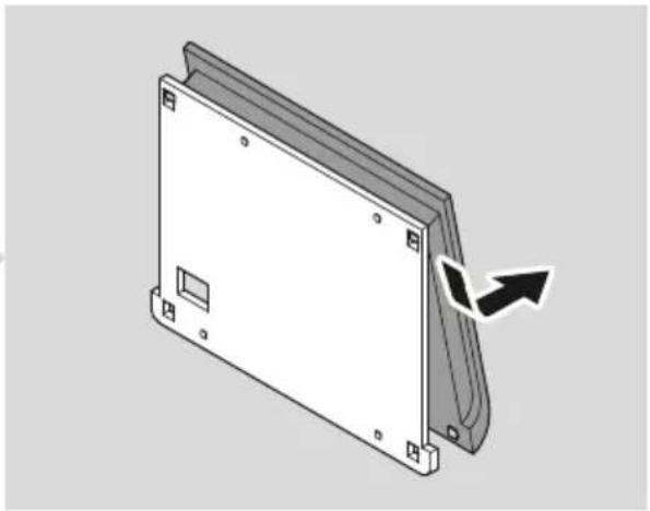
8 Installation
Mounting the display
9

natural_image
3D diagram of a rectangular electronic device with mounting holes and a curved panel, showing a directional arrow (no text or symbols)


natural_image
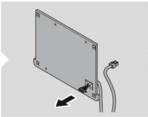
Diagram of a device rear panel with cable and connector, showing a directional arrow (no text or symbols)
EN Dometic TD283
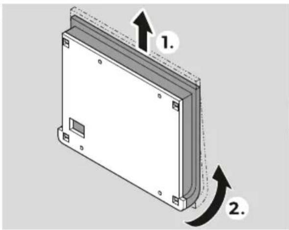
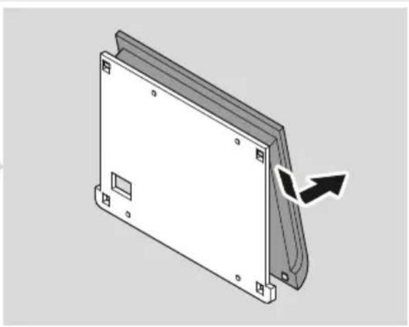
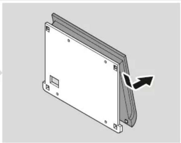
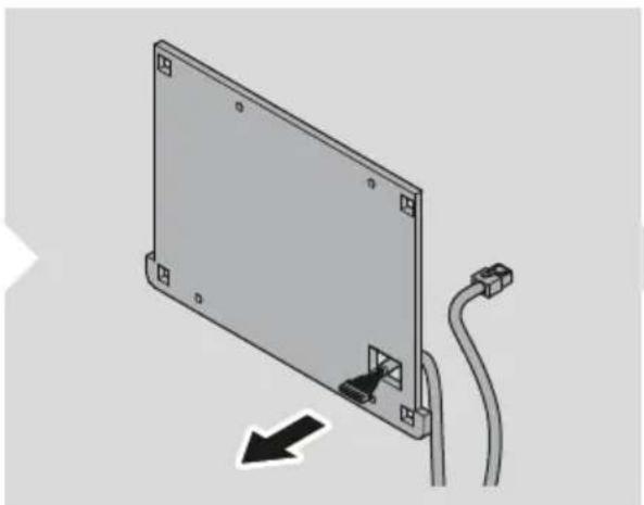
- Detach the mounting plate from the display cover.
- Place the mounting plate on the mounting surface and mark the mounting holes and the communication cable connection.
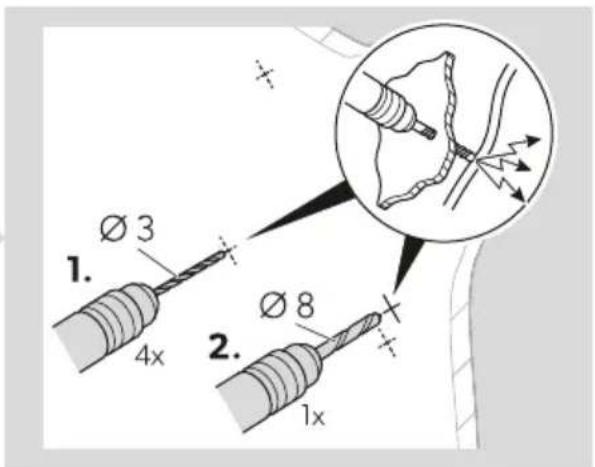
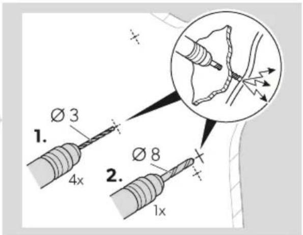
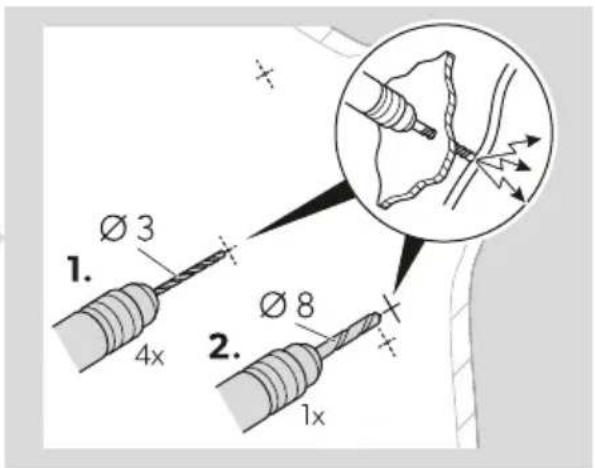
- Drill mounting holes for the mounting plate ( 3 mm) and an opening for the communication cable connection ( 8 mm) at the marked points.
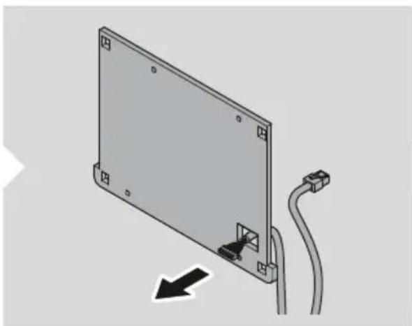
- Route the communication cable through the communication cable connection and the prepared hole in the mounting surface.
- Screw the mounting plate to the mounting surface.
Connecting the display
10
natural_image
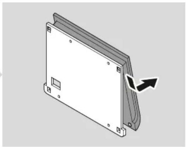
Technical line drawing of a mechanical assembly with a lever and mounting bracket (no text or symbols)
natural_image
Diagram of a computer monitor mounted on an open panel, showing cable and wiring (no text or symbols)
natural_image
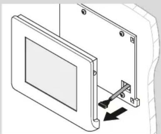
Diagram of a door frame with a black arrow indicating a downward motion (no text or symbols present)- Connect the communication cable to the display.
- Attach the display cover to the mounting plate.
Connecting N-BUS devices

NOTE Use N-BUS connection cables (accessories) when connecting N-BUS-capable devices.
9 Operation
Setting up the display
When the device is switched on for the first time, the initial setup for setting the language, date, time, and type of battery used is started automatically (refer to the corresponding chapter for more details on the individual settings).
The settings can be skipped and edited or changed at any time in the settings menu.

NOTE For the display to function correctly, the battery type used, the nominal capacity and the corresponding charging profile must be set for the house battery currently connected (see chapter Making basic settings for the battery on page 20).
Using the display
Switching the display on
Press the power switch or tap the touchscreen to switch the display on (Fig. 11 on page 17).

natural_image
Isometric line drawing of a rectangular panel with a recessed edge and a small inset showing a dark arrow pointing to the edge (no text or symbols)Switching the display to standby

NOTE
By default, the display automatically switches to standby mode after 3 min without operation. The default setting can be adjusted (see chapter Setting a standby time on page 19).
Press the power switch to switch the display to standby (Fig. 11 on page 17).
Switching N-BUS-capable devices in the network on and off

NOTE The display can be used to activate and deactivate all N-BUS-capable devices in the network.
Tap the power button for at least 3 s (Fig. 12 on page 18) to switch off the display and all N-BUS-capable devices in the network.
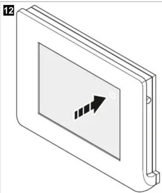
natural_image
Isometric illustration of a rectangular device with a screen showing an arrow symbol (no text or labels)Press the power switch to switch on the display and all N-BUS-capable devices in the network (Fig. 11 on page 17).
Setting values
Select - or t - decrease or increase the values.
Navigating through the menus
Select ← r → navigate forwards or backwards in the menus.
Select to return to the main menu.
Activating or deactivating the Bluetooth function of connected devices
The display can be used to control the Bluetooth modules of the connected N-BUS devices.

NOTE
- Ensure that the connected devices to be controlled have a Bluetooth function.
-
The Bluetooth modules of all connected N-BUS devices are controlled simultaneously. The devices cannot be specifically selected.
-
Select to open the settings menu.
-
Select or clear the checkbox next to Bluetooth to activate or deactivate the Bluetooth function of connected N-BUS devices.
√ As soon as the Bluetooth function is activated, the symbol in the status bar lights up yellow.
Opening an overview of connected N-BUS devices
- Select to open the settings menu.
- Go to BUS.
A list of the connected N-BUS devices is displayed. The master interface is highlighted in blue.
Making settings
Setting a standby time
13

NOTE By default, the display automatically switches to standby mode after 3 min without operation.
-
Select to open the settings menu.
-
Go to Display.
-
Set a value between 1 and 100 for the time (in minutes) after which the backlight is to be dimmed (2). With the backlight dimmed, the power consumption of the display is reduced to half of the power consumption at full brightness (see chapter Technical data on page 24).
-
Set a value between 1 and 100 for the time (in minutes) after which the display switches to standby automatically (1).
In standby mode, the display backlight is completely switched off, the power consumption of the display is reduced to 15 mA (see chapter Technical data on page 24).
Setting the button and warning tone signals
- Select to open the settings menu.
- Go to Display.
- Select or clear the checkbox next to BEEP to activate or deactivate the acoustic signal (see Fig. 13 on page 19).
Setting the silent mode
With silent mode activated, the fan (if present) of connected N-BUS devices is switched off and the devices charge at reduced power to prevent overheating.

NOTE The setting is only available if at least an N-BUS-capable battery charger or solar charge controller is connected in the N-BUS network.
- Select to open the settings menu.
- Select or clear the checkbox next to Silent Mode to activate or deactivate the silent mode.
Setting the date and time
- Select to open the settings menu.
- Go to Date&Time.
- Date Enter the day, month and year.
- Time Enter the hours and minutes.
Setting the language
- Select to open the settings menu.
- Go to Language.
- Select the checkbox next to the desired language to choose the language.
The following languages are available:
- Italian
- English
• German - French
- Spanish
• Dutch
Making basic settings for the battery
For the display to function correctly, the battery type used, the nominal capacity and the corresponding charging profile must be set for the house battery currently connected.

NOTE If the TEMPRA battery (TLB 100(F)-150(F)) is connected as a house battery, these settings are predefined and cannot be changed.
Setting the battery type and the rated capacity
14
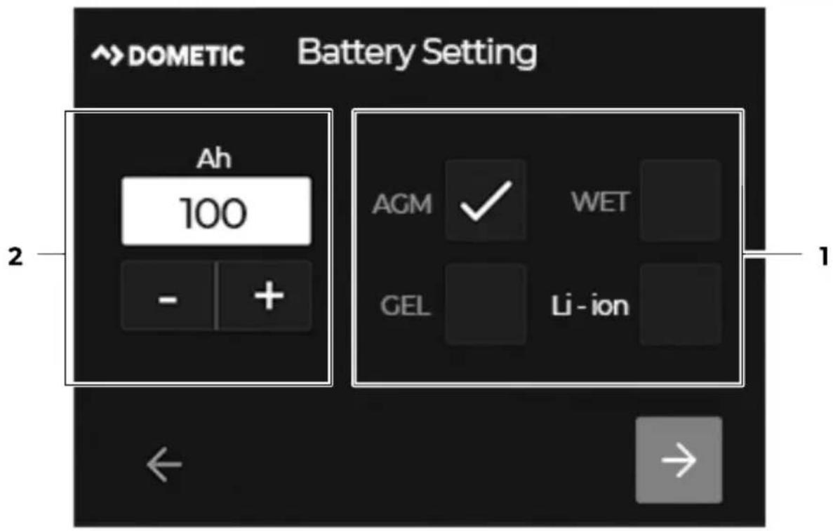
- Select to open the settings menu.
- Go to Battery.
- Enter the rated capacity of the house battery (in Ah) (2).
- Select the checkbox next to the battery type used (1).
The following battery types are supported:
• AGM (Absorbed glass mat batteries)
• WET (Lead acid batteries)
• GEL (Lead gel batteries)
• Li-ion (Lithium-ion battery)
Setting the charging profile

NOTICE! Damage hazard
Only select a charging profile that is suitable for the battery used based on the manufacturer's specifications. Incorrect settings can lead to malfunctions and damage to the batteries. If in doubt, contact a qualified electrician.

NOTE The setting is only available if at least an N-BUS-capable battery charger or solar charge controller is connected in the N-BUS network.
15
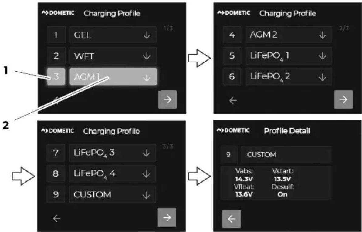
- Select to open the settings menu.
- Go to Charging profile.
- Select the number next to the suitable charging profile to set a preset charging profile (1 - 8, e.g. 3 for AGM1, see Fig. 15 on page 22, 1).
- Select number 9 to set a customized charging profile (see chapter Setting a customized battery charging profile on page 22).
√ The number of the activated charging profile is highlighted.
- Select the field of a charging profile to view the profile details (e.g. AGM1, see Fig. 15 on page 22, 2). Description:
V_abs Absorption voltage
V_start Battery voltage at the start of the charging process
V_float Float voltage
Desulf Desulfation, optional charging phase for lead-acid batteries (AGM2) to remove sulphate from the lead plates of the battery and restore the battery capacity. Note: Use the charging phase only when necessary, as excessive use will shorten the life of the battery.
Setting a customized battery charging profile
- Select to open the settings menu.
- Go to Charging profile.
- Select CUSTOM.
- Enter values for V_abs , V_float and V_start .
-
Select . →
-
Select the checkbox next to Float to activate the trickle charging phase (Float).
-
Select the checkbox next to Recondition to activate the reconditioning phase.
AGM2 batteries only: Desulfation phase (Desulf) is activated when the corresponding charging program is selected.
- Enter the value (in A) for the maximum charging current of all connected chargers.
Making basic settings for the solar charge controller
For the display to function correctly, the nominal output (in Wp) for the connected solar panels must be set.

NOTE The setting is only available if an N-BUS-capable solar charge controller is connected in the N-BUS network.
-
Select to open the settings menu.
-
Go to Solar Panel.
-
Enter the nominal output (in Wp) for up to 2 solar panels (PS1 and PS2).
10 Cleaning and maintenance

NOTICE! Damage hazard
- Do not use abrasive cleaning agents or hard objects during cleaning as these may damage the device.
- Do not use cleaning agents that contain ammonia or alcohol.
- Never spray or pour liquid directly onto the touchscreen or casing.
Clean the touchscreen with a clean and dry microfiber cloth in small circular motions. Slightly moisten the microfiber cloth if necessary.
Occasionally clean the casing with a damp cloth.
11 Troubleshooting
| Problem Possible cause Suggested remedy | ||
| The display does not work. No values are measured. | The communication cable is not connected correctly or defective. | > Check the connection cable for loose connections or insulation faults and breaks.> Replace the communication cable if necessary. |
| Insulation faults, breaks or loose connections at the live cables of the connected N-BUS devices. | > Check the live cables for insulation faults, breaks or loose connections. | |
| The house battery voltage is too low (Q 7 V). | > Check the house battery voltage. Recharge the house battery if necessary. | |
12 Disposal

Place the packaging material in the appropriate recycling waste bins wherever possible. Consult a local recycling center or specialist dealer for details about how to dispose of the product in accordance with the applicable disposal regulations. The product can be disposed free of charge.
Deleting personal data: If the product contains a data storage, delete any personal data from this data storage before disposing the product.
13 Warranty
The statutory warranty period applies. If the product is defective, please contact the manufacturer's branch in your country (see dometic.com/dealer) or your retailer.
For repair and warranty processing, please include the following documents when you send in the device:
• A copy of the receipt with purchasing date
- A reason for the claim or description of the fault
Note that self-repair or nonprofessional repair can have safety consequences and might void the warranty.
14 Technical data
Display type TFT 2.83", 262k full color touchscreen
Average power consumption
Backlight set to maximum value 54 mA
Standby mode 15 mA
Ambient temperature for operation – 10 ... 70 °C
Dimensions 79 × 100 × 12 mm
Weight 70 g
Certification

Deutsch
1 Wichtige Hinweise
Pos. Beschreibung

natural_image
3D diagram of a rectangular electronic device with mounting holes and a curved panel, showing a directional arrow (no text or symbols)


natural_image
Diagram of a device rear panel with cable and connector, showing no text or symbols
DE Dometic TD283
natural_image
Technical line drawing of a mechanical assembly with a lever and mounting bracket (no text or symbols)
natural_image
Diagram of a mounted electronic device with an arrow indicating direction, showing internal components and wiring (no text or symbols)
natural_image
Diagram of a rectangular frame with a downward arrow indicating a force or change, no text or symbols present.natural_image
Diagram of a rectangular electronic device with a screen and a side port, showing an arrow pointing to a small component (no text or symbols present)natural_image
Isometric illustration of a rectangular device with a screen showing an arrow symbol (no text or labels)7 Description technique
Pos. Description

natural_image
3D diagram of a rectangular electronic device with mounting holes and a black arrow indicating a directional change (no text or symbols)


natural_image
Diagram of a device rear panel with cable and connector, showing a directional arrow (no text or symbols)
FR Dometic TD283
natural_image
Technical line drawing of a mechanical assembly with a lever and mounting bracket (no text or symbols)
natural_image
Diagram of a mounted electronic device with an arrow indicating direction, showing internal components and wiring (no text or symbols)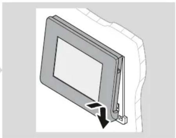
natural_image
Diagram of a rectangular panel with a downward arrow indicating compression or dislocation (no text or symbols present)natural_image
Isometric line drawing of a rectangular panel with a side panel and a close-up corner, showing a small inset detail (no text or symbols)natural_image
Isometric illustration of a rectangular device with a screen showing an arrow symbol (no text or labels)Pos. Descripción

natural_image
3D diagram of a rectangular electronic device with mounting holes and a curved panel, showing a directional arrow (no text or symbols)


natural_image
Diagram of a device rear panel with cable and connector, showing no text or symbols
ES Dometic TD283
natural_image
Technical line drawing of a mechanical assembly with a lever and mounting bracket (no text or symbols)
natural_image
Diagram of a mounted electronic device with an arrow indicating direction, showing internal components and wiring (no text or symbols)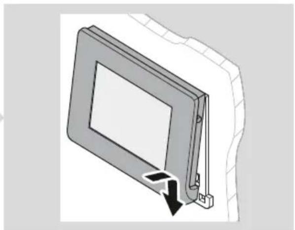
natural_image
Diagram of a rectangular frame with a downward arrow indicating a force or change, no text or symbols present.natural_image
Diagram of a rectangular electronic device with a screen and a side port, showing an arrow pointing to a small component (no text or symbols present)natural_image
Isometric illustration of a rectangular device with a screen showing an arrow symbol (no text or labels)Pos. Descrição
natural_image
3D diagram of a rectangular electronic device with mounting holes and a curved panel, showing a directional arrow (no text or symbols)


natural_image
Diagram of a device rear panel with cable and connector, showing a directional arrow (no text or symbols)
PT Dometic TD283
natural_image
Technical line drawing of a mechanical assembly with a lever and mounting bracket (no text or symbols)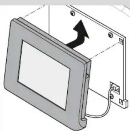
natural_image
Diagram of a device with an arrow indicating direction, showing a mounted panel or enclosure (no text or symbols present)
natural_image
Diagram of a rectangular panel with a downward arrow indicating compression or dislocation (no text or symbols present)natural_image
Isometric line drawing of a rectangular panel with a side panel and a close-up corner, showing a small inset detail (no text or symbols)natural_image
Isometric illustration of a rectangular device with a screen and an arrow symbol, no text or labels presentPos. Descrizione

natural_image
3D diagram of a rectangular electronic device with mounting holes and a curved panel, showing a directional arrow (no text or symbols)


natural_image
Diagram of a device rear panel with cable and connector, showing a directional arrow (no text or symbols)
IT Dometic TD283
natural_image
Technical line drawing of a mechanical assembly with a lever and mounting bracket (no text or symbols)
natural_image
Diagram of a computer monitor mounted on an open panel, showing cable and wiring (no text or symbols)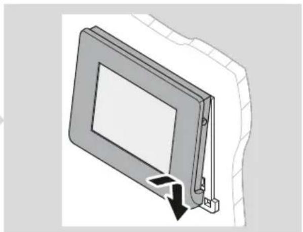
natural_image
Diagram of a door frame with a black arrow indicating a downward motion (no text or symbols present)natural_image
Diagram of a rectangular electronic device with a screen and a side port, showing an arrow pointing to a small component (no text or symbols present)natural_image
Isometric illustration of a rectangular device with a screen showing an arrow symbol (no text or labels)Nr. Beschrijving

natural_image
3D diagram of a rectangular electronic device with mounting holes and a curved panel, showing a black arrow indicating rotation (no text or symbols)

natural_image
Diagram of a device rear panel with cable and connector, showing a directional arrow (no text or symbols)
NL Dometic TD283
natural_image
Technical line drawing of a mechanical assembly with a lever and mounting bracket (no text or symbols)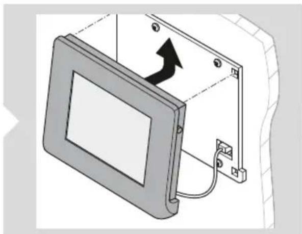
natural_image
Diagram of a computer monitor mounted on an open panel, showing cable and wiring (no text or symbols)
natural_image
Diagram of a door frame with a black arrow indicating a downward motion (no text or symbols present)natural_image
Isometric line drawing of a rectangular panel with a recessed edge and a small inset showing a dark arrow pointing to a small square (no text or symbols)Display in stand-by zetten

INSTRUCTIE
natural_image
Isometric illustration of a rectangular device with a screen showing an arrow symbol (no text or labels)Pos. Beskrivelse

natural_image
3D diagram of a rectangular electronic device with mounting holes and a curved panel, showing a directional arrow (no text or symbols)


natural_image
Diagram of a device rear panel with cable and connector, showing a directional arrow (no text or symbols)
DA Dometic TD283
natural_image
Technical line drawing of a mechanical assembly with a lever and mounting bracket (no text or symbols)
natural_image
Diagram of a device with an arrow indicating direction, showing a mounted panel or enclosure (no text or symbols present)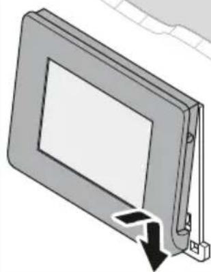
natural_image
Diagram of a rectangular panel with a downward arrow indicating compression or dislocation (no text or symbols present)natural_image
Diagram of a rectangular device with a recessed panel and a pointed tip, showing an arrow indicating direction (no text or symbols present)Sætter displayet på standby

BEMÆRK
natural_image
Isometric illustration of a rectangular device with a screen showing an arrow symbol (no text or labels)Pos. Beskrivning
| 1 | Displayskydd |
| 2 | Pekskärm |
| 3 | Kommunikationskabelanslutning |
| 4 | Strömbrytare |
| 5 | Strömbrytare |
| 6 | Monteringshål |
| 7 | Monteringsplatta |
| 8 | Upphängningshål |
Pekskärm
3
Pos. Komponent Beskrivning

natural_image
3D diagram of a rectangular electronic device with mounting holes and a curved panel, showing a directional arrow (no text or symbols)

natural_image
Diagram of a device rear panel with cable and connector, showing a directional arrow (no text or symbols)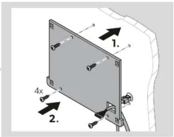
SV Dometic TD283
natural_image
Technical line drawing of a mechanical assembly with a lever and mounting bracket (no text or symbols)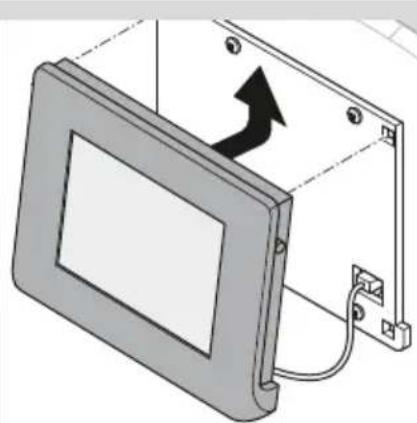
natural_image
Diagram of a monitor mounted on an electrical panel with a right-handled arrow indicating rotation (no text or symbols present)
natural_image
Diagram of a rectangular panel with a downward arrow indicating compression or dislocation (no text or symbols present)natural_image
Diagram of a rectangular device with a recessed panel and a pointed tip, showing an arrow indicating direction (no text or symbols present)natural_image
Isometric illustration of a rectangular device with a screen showing an arrow symbol (no text or labels)Pos. Betegnelse Antall
| 1 Display-deksel 1 |
| 2 Montasjeplate 1 |
| 3 Skruer 4 |
| 4 Kommunikasjonskabel 1 |
5 Tilbehør
Betegnelse Art.nr.
| Dometic NDS BC10M (N-BUS-tilkoblingskabel, 10 m) 9620008182 |
| Dometic NDS BC06M (N-BUS-tilkoblingskabel, 6 m) 9620008462 |
| Dometic NDS BC03M (N-BUS-tilkoblingskabel, 3 m) 9620008275 |
Pos. Beskrivelse
Laderegulator for solcelleanlegg

Batteriladermeny

Husbatterimeny

Vekselrettermeny
Hovedmeny
4

Pos. Beskrivelse
| 1 | Status til husbatteriet (På/Av) |
| Spenning (i V) til startbatteriet | |
| 2 | Statusen til batteriladeren (Standby/Bulk/Absorpsjon/Float/Av) |
| Strømforsyning (i A) fra batteriladeren | |
| 3 | Statusen til vekselretteren (På/Av) |
| Utgangsspenning (i V) til vekselretteren | |
| 4 | Statusen til laderegulatoren for solcelleanlegg (Standby/MPPT/Absorpsjon/Float/Av) |
| Strømforsyning (i A) fra laderegulatoren til solcelleanlegg | |
| 5 | Ladestatusen (SoC) til husbatteriet (sirkeldiagram i 25 %* trinn) med gjeldende verdier for spenning (i V) og strøm (i A) |
| * Merk: Hvis et TEMPRA-batteri (TLB 100(F)-150(F)) er koblet til N-BUS nettverket, vises ladestatusen (SoC) i 5 % trinn |
Laderegulator for solcelleanlegg
5
Pos. Beskrivelse

natural_image
3D diagram of a rectangular electronic device with mounting holes and a curved panel, showing a black arrow indicating direction (no text or symbols)


natural_image
Diagram of a device rear panel with cable and connector, showing a directional arrow (no text or symbols)
NB Dometic TD283
natural_image
Technical line drawing of a mechanical assembly with a tool inserted into a panel (no text or symbols)
natural_image
Diagram of a monitor mounted on an electrical panel with a right-handled arrow indicating rotation (no text or symbols present)
natural_image
Diagram of a rectangular frame with a black arrow indicating a downward motion or force, no text or symbols present.natural_image
Isometric line drawing of a rectangular panel with a side panel and a close-up corner, showing an arrow pointing to a small inset detail (no text or symbols)Slå på displayet til standbymodus.

MERK
natural_image
Isometric illustration of a rectangular device with a screen showing an arrow symbol (no text or labels)Nro Kuvaus

natural_image
3D diagram of a rectangular electronic device with mounting holes and a black arrow indicating a directional change (no text or symbols)


natural_image
Diagram of a device rear panel with cable and connector, showing a directional arrow (no text or symbols)
FI Dometic TD283
natural_image
Technical line drawing of a mechanical assembly with a lever and mounting bracket (no text or symbols)
natural_image
Two technical diagrams showing a device mounting frame with a right-hand arrow indicating rotation (no text or symbols present)natural_image
Diagram of a rectangular panel with a side panel and a corner clip, showing an arrow pointing to a small inset (no text or symbols present)natural_image
Isometric illustration of a rectangular device with a screen showing an upward arrow symbol (no text or labels)Poz. Opis

natural_image
3D diagram of a rectangular electronic device with mounting holes and a curved panel, showing a directional arrow (no text or symbols)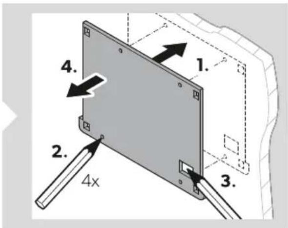


natural_image
Diagram of a device rear panel with cable and connector, showing a directional arrow (no text or symbols)
PL Dometic TD283
natural_image
Technical line drawing of a mechanical assembly with a lever and mounting bracket (no text or symbols)
natural_image
Diagram of a computer monitor mounted on an open panel, showing cable and wiring (no text or symbols)
natural_image
Diagram of a door frame with a black arrow indicating a downward motion (no text or symbols present)natural_image
Diagram of a rectangular electronic device with a screen and a side port, showing an arrow pointing to a small component (no text or symbols present)natural_image
Isometric illustration of a rectangular device with a screen showing an upward arrow symbol (no text or labels)Poz. Opis
natural_image
3D diagram of a rectangular electronic device with mounting holes and a black arrow indicating direction (no text or symbols)

natural_image
Diagram of a device rear panel with cable and connector, showing a directional arrow (no text or symbols)
natural_image
Diagram of a device with a screwdriver inserted into a panel, showing no text or symbols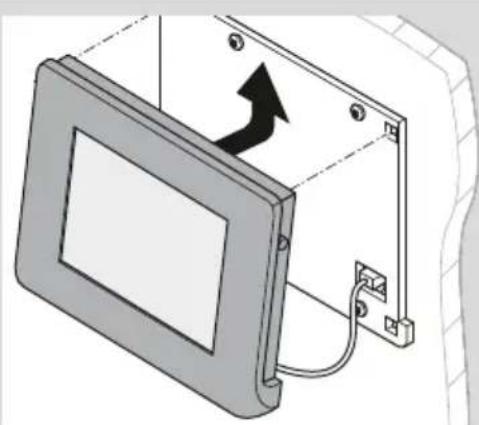
natural_image
Diagram of a computer monitor with an arrow indicating rotation or movement, mounted on a wall (no text or symbols present)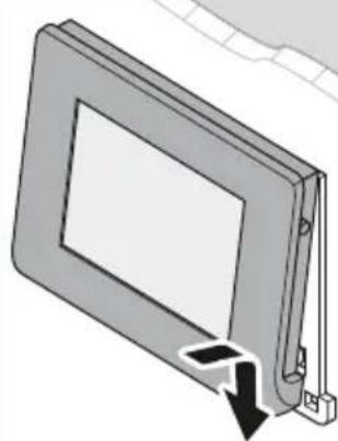
natural_image
Diagram of a rectangular panel with a black arrow pointing to its side, showing a cut or assembly (no text or symbols present)natural_image
Diagram of a rectangular device with a recessed panel and a black arrow pointing to a small component (no text or symbols)natural_image
Isometric illustration of a rectangular device with a screen and an arrow symbol, no text or labels presentPol. Popis

natural_image
3D diagram of a rectangular electronic device with mounting holes and a black arrow indicating direction (no text or symbols)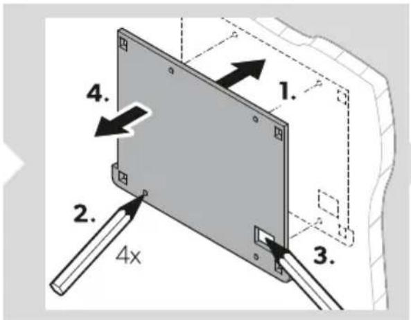


natural_image
Diagram of a device rear panel with cable and connector, showing no text or symbols
natural_image
Technical line drawing of a mechanical assembly with a lever and mounting bracket (no text or symbols)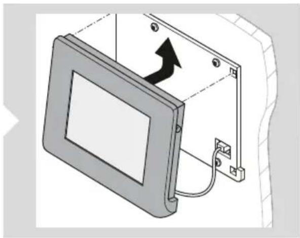
natural_image
Diagram of a computer monitor mounted on an open panel, showing cable and wiring (no text or symbols)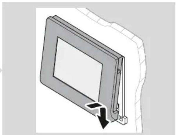
natural_image
Diagram of a rectangular panel with a downward arrow indicating a change or movement (no text or symbols present)natural_image
Diagram of a rectangular device with a recessed panel and a black arrow pointing to a small component (no text or symbols)natural_image
Isometric illustration of a rectangular device with a screen showing an arrow symbol (no text or labels)Poz. Leírás

natural_image
3D diagram of a rectangular electronic device with mounting holes and a black arrow indicating a directional change (no text or symbols)


natural_image
Diagram of a device rear panel with cable and connector, showing a directional arrow (no text or symbols)
HU Dometic TD283
natural_image
Technical line drawing of a mechanical assembly with a lever and mounting bracket (no text or symbols)
natural_image
Diagram of a monitor mounted on an electrical panel with a black arrow indicating direction (no text or symbols present)
natural_image
Diagram of a rectangular panel with a downward arrow indicating compression or dislocation (no text or symbols present)natural_image
Isometric line drawing of a rectangular panel with a recessed edge and a small inset showing a dark arrow pointing to a cut section (no text or symbols)natural_image
Isometric illustration of a rectangular device with a screen showing an arrow symbol (no text or labels)Poz. Naziv Količina
| 1 Pokrov zaslona 1 |
| 2 Montažna ploča 1 |
| 3 Vijci 4 |
| 4 Komunikacijski kabel 1 |
5 Pribor
Naziv Br. art.
| Dometic NDS BC10M (priključni kabel za N-BUS, 10 m) 9620008182 |
| Dometic NDS BC06M (priključni kabel za N-BUS, 6 m) 9620008462 |
| Dometic NDS BC03M (priključni kabel za N-BUS, 3 m) 9620008275 |
6 Namjena
Zaslon je osmišljen kao kontrolni uređaj za akumulator, koji prikazuje i prati trenutačno stanje napunjenosti, napona i struje akumulatora vozila koja koriste N-BUS te za upravljanje N-BUS uređajima u mreži.
Poz. Opis
natural_image
3D diagram of a rectangular electronic device with mounting holes and a black arrow indicating rotation (no text or symbols)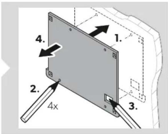


natural_image
Diagram of a device with a cable and connector, showing an arrow indicating direction (no text or symbols present)
- Odvojite montažnu ploču od pokrova zaslona.
- Montažnu ploču postavite na montažnu površinu pa označite montažne rupe i spoj za komunikacijski kabel.
- Na naznačenim točkama izbušite montažne rupe za montažnu ploču ( 3 mm) i otvor za spoj komunikacijskog kabela ( 8 mm).
-
Komunikacijski kabel provedite kroz predviđeni kabelski spoj i pripremljenu rupu u montažnoj površini.
-
Montažnu ploču vijcima pričvrstite za montažnu površnu.
natural_image
Diagram of a wall-mounted device with a cable inserted, showing a black tool inserted into the panel (no text or symbols present)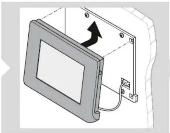
natural_image
Diagram of a computer monitor with an attached cable and wall-mounted connectors, showing no text or symbols.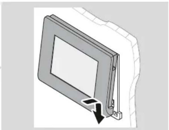
natural_image
Diagram of a door frame with a black arrow indicating a downward motion (no text or symbols present)- Komunikacijski kabel priključite na zaslon.
- Pokrov zaslona pričvrstite na montažnu ploču.
natural_image
Isometric line drawing of a rectangular panel with a recessed edge and a small inset showing a dark arrow pointing to the edge (no text or symbols)Prebacivanje zaslona u stanje pripravnosti

UPUTA
Po zadanim se postavkama zaslon automatski prebacuje u stanje pripravnosti nakon 3 min bez aktivnosti. Zadanu je postavku moguće prilagoditi (pogledajte odjeljak Postavljanje vremena pripravnosti na strani-ci 350).
natural_image
Isometric illustration of a rectangular electronic device with a screen and an arrow symbol (no text or labels)Konum Adı

natural_image
3D diagram of a rectangular electronic device with mounting holes and a black arrow indicating direction (no text or symbols)


natural_image
Diagram of a device rear panel with cable and connector, showing a directional arrow (no text or symbols)
natural_image
Technical line drawing of a mechanical assembly with a lever and mounting bracket (no text or symbols)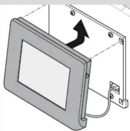
natural_image
Diagram of a device with an arrow indicating rotation or movement, showing a panel mounted on a bracket (no text or symbols present)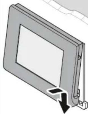
natural_image
3D diagram of a rectangular frame with a black arrow indicating a downward motion or force, no text or symbols present.natural_image
Isometric line drawing of a rectangular panel with a side panel and a corner clip, showing an arrow pointing to a small inset (no text or symbols)natural_image
Isometric illustration of a rectangular device with a screen showing an arrow symbol (no text or labels)Pol. Oznaka Količina
Pol. Opis

natural_image
3D diagram of a rectangular electronic device with mounting holes and a black arrow indicating direction (no text or symbols)

natural_image
Diagram of a device rear panel with cable and connector, showing a directional arrow (no text or symbols)
natural_image
Technical line drawing of a mechanical assembly with a lever and mounting bracket (no text or symbols)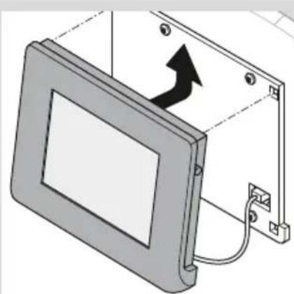
natural_image
Diagram of a device with an arrow indicating direction, showing a mounted panel and cable (no text or symbols present)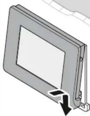
natural_image
Diagram of a rectangular panel with a black arrow indicating downward motion (no text or symbols)natural_image
Isometric line drawing of a rectangular panel with a recessed edge and a small inset showing a dark arrow pointing to a cut (no text or symbols)Preklop zaslona v stanje pripravljenosti

NASVET
Zaslon privzeto preklopi v stanje pripravljenosti po 3 min brez delovanja.
natural_image
Isometric illustration of a rectangular device with a screen showing an arrow symbol (no text or labels)Poz. Denumire

natural_image
3D diagram of a rectangular electronic device with mounting holes and a curved panel, showing a directional arrow (no text or symbols)


natural_image
Diagram of a device rear panel with cable and connector, showing a directional arrow (no text or symbols)
natural_image
Technical line drawing of a mechanical assembly with a lever and mounting bracket (no text or symbols)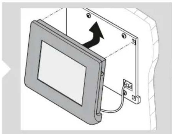
natural_image
Diagram of a monitor mounted on an electrical panel with a black arrow indicating direction (no text or symbols present)
natural_image
Diagram of a rectangular panel with a downward arrow indicating compression or dislocation (no text or symbols present)natural_image
Isometric line drawing of a rectangular panel with a recessed edge and a small inset showing a dark arrow pointing to a cut (no text or symbols)natural_image
Isometric illustration of a rectangular device with a screen and an arrow symbol, no text or labels presentПоз. Описание

natural_image
3D diagram of a rectangular electronic device with mounting holes and a black arrow indicating direction (no text or symbols)


natural_image
Diagram of a device rear panel with cable and connector, showing no text or symbols
natural_image
Technical line drawing of a mechanical assembly with a lever and mounting bracket (no text or symbols)
natural_image
Diagram of a computer monitor mounted on an open panel, showing a black arrow indicating rotation (no text or symbols present)
natural_image
Diagram of a door frame with a black arrow indicating a downward motion (no text or symbols present)natural_image
Diagram of a rectangular device with a panel and a close-up corner, showing an arrow pointing to a small component (no text or symbols present)natural_image
Isometric illustration of a rectangular device with a screen showing an arrow symbol (no text or labels)| Nr Nimetus Kogus |
| 1 Ekraani kate 1 |
| 2 Paigaldusplaat 1 |
| 3 Kruvid 4 |
| 4 Sidekaabel 1 |
5 Lisatarvikud
Nr Tähistus

natural_image
3D diagram of a rectangular electronic device with mounting holes and a black arrow indicating direction (no text or symbols)


natural_image
Diagram of a device rear panel with cable and connector, showing a directional arrow (no text or symbols)
natural_image
Technical line drawing of a device with a screw and lever attachment (no text or symbols)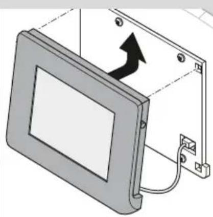
natural_image
Diagram of a computer monitor with an arrow indicating rotation, shown in 3D without any text or symbols.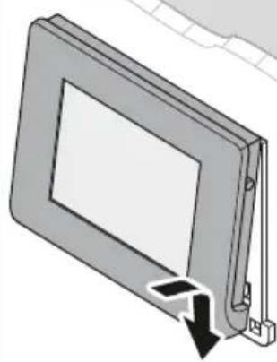
natural_image
Diagram of a rectangular panel with a black arrow indicating a downward motion or force, no text or symbols present.natural_image
Diagram of a rectangular device with a side panel and a close-up corner, showing an arrow pointing to a small component (no text or symbols present)natural_image
Isometric illustration of a rectangular device with a screen showing an arrow symbol (no text or labels)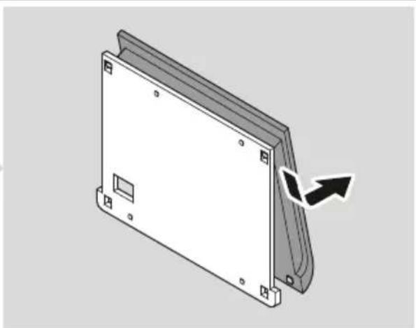
natural_image
3D diagram of a rectangular electronic device with mounting holes and a curved arrow indicating rotation (no text or symbols)
natural_image
Diagram of a device with connectors and cables, showing a directional arrow indicating movement (no text or symbols present)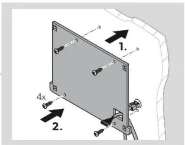
natural_image
Technical line drawing of a mechanical assembly with a lever and mounting bracket (no text or symbols)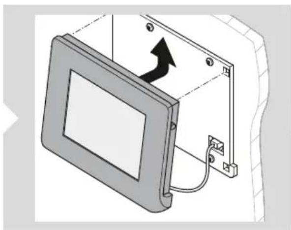
natural_image
Diagram of a device with an arrow indicating direction, showing internal components and wiring (no text or symbols)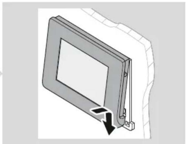
natural_image
Diagram of a rectangular frame with a downward arrow indicating a force or change, no text or symbols present.natural_image
Isometric line drawing of a rectangular panel with a recessed top and a small inset showing a dark arrow pointing to the edge (no text or symbols)natural_image
Isometric view of a rectangular electronic device with a screen displaying an arrow symbol (no text or labels)Pad. Aprašymas

natural_image
3D diagram of a rectangular electronic device with mounting holes and a curved panel, showing a black arrow indicating rotation (no text or symbols)


natural_image
Diagram of a device rear panel with cable and connector, showing a directional arrow (no text or symbols)
natural_image
Technical line drawing of a device with a screw and lever attachment (no text or symbols)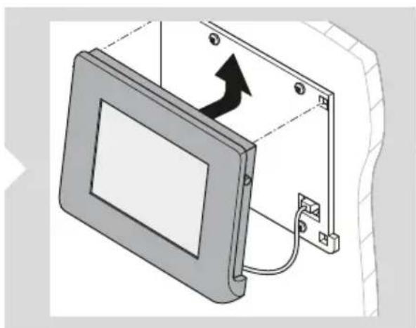
natural_image
Diagram of a device with an arrow indicating direction, showing a mounted panel or enclosure (no text or symbols present)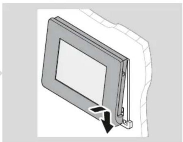
natural_image
Diagram of a rectangular panel with a black arrow indicating a downward motion or force, no text or symbols present.natural_image
Diagram of a rectangular device with a recessed panel and a black arrow pointing to a small component (no text or symbols)natural_image
Isometric illustration of a rectangular device with a screen showing an arrow symbol (no text or labels)Poz. Apraksts
natural_image
3D diagram of a rectangular electronic device with mounting holes and a black arrow indicating direction (no text or symbols)


natural_image
Diagram of a device rear panel with cable and connector, showing a directional arrow (no text or symbols)
natural_image
Technical line drawing of a device with a cable inserted into a panel, showing a black arrow indicating direction (no text or symbols present)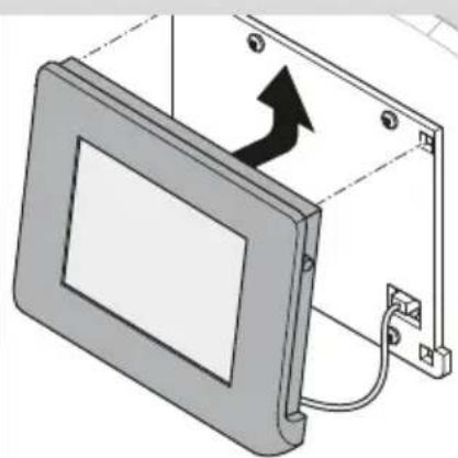
natural_image
Diagram of a computer monitor with an attached bracket and cable, showing a black arrow indicating direction (no text or symbols present)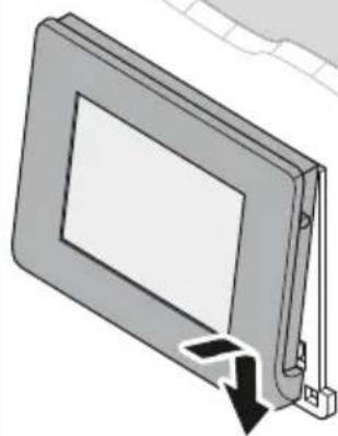
natural_image
Diagram of a rectangular frame with a black arrow indicating downward motion, no text or symbols presentnatural_image
Isometric line drawing of a rectangular panel with a recessed edge and a small inset showing a dark arrow pointing to a cut (no text or symbols)natural_image
Isometric illustration of a rectangular device with a screen showing an upward arrow and grid pattern (no text or symbols)dometic.com/sales-offices