
CapTouch - Thermostat DOMETIC - Free user manual and instructions
Find the device manual for free CapTouch DOMETIC in PDF.

| Product Type | Capacitive Touch Screen Thermostat |
| Brand | Dometic |
| Model | CapTouch |
| Power Supply | 100-120 V~ or 200-260 V~ (depending on model), 50/60 Hz |
| Power Consumption | 5 VA (standby) |
| Temperature Setting Range | 4.4 °C to 37.8 °C (40 °F to 100 °F) |
| Sensor Accuracy | ±0.5 °C (±1 °F) |
| Operating Modes | Auto, Cool, Heat, Fan Only, Dehumidification (Humidity Control), Aux Heat |
| Fan Speeds | Automatic and manual (5 speeds) |
| Built-in Sensors | Ambient temperature, humidity sensor (optional) |
| Optional Sensors | Water temperature, outdoor temperature, combined humidity sensor, low water limit, Dump Sentry |
| Display | Indoor/set point/outdoor/water temperature, relative humidity |
| System Compatibility | Direct expansion (DX) and hydronic (CW) systems, heat pump, cooling only, auxiliary electric heat |
| Safety Functions | High/low pressure protection, low voltage, lockout after repeated errors, automatic shutdown |
| Maintenance | Air filter cleaning, filter timer reset |
| Spare Parts | Interchangeable frames (Amar, Idea, Simon), additional sensors, display cable |
| Repairability | Service by qualified technician, printed circuit board replacement |
| Warranty | Limited warranty (depending on region), contact local service |
| Dimensions (approx.) | Fits standard frames, dimensions not specified |
| Weight | Not specified |
Frequently Asked Questions - CapTouch DOMETIC
User questions about CapTouch DOMETIC
0 question about this device. Answer the ones you know or ask your own.
Ask a new question about this device
Download the instructions for your Thermostat in PDF format for free! Find your manual CapTouch - DOMETIC and take your electronic device back in hand. On this page are published all the documents necessary for the use of your device. CapTouch by DOMETIC.
USER MANUAL CapTouch DOMETIC
Installation and Operating Manual....U
DE
Cabin Control
H I J I K L ometic Mroup. Nhe visual appearance of the contents of this manual is protected by copyright and design law. Nhe underlying technical design and the products contained herein may be protected by design ^9 patent or pending patent. Nhe trademarks mentioned in this manual belong to L ometic Sweden " B." ll rights are reserved.
English
Q Related documents.... U
I STplanation of symbols....U
U Intended use..... U
K Meneral information.... U
V Specifications....K
X Y iring diagrams....V
Z Installation....V
[ Operation....X
9' avigation tree......OK
0) Troubleshooting....0V
00 L isposal.....CZ
QI Y arranty.....QZ
1 R' lat' ( ( ocu) ' nts

] ind the installation and operating manual online on qr.dometic.com/bes|p'.
2 Explanation o, sy) bols
* signal word will identify safety messages and property damage messages; and also will indicate the degree or level of hazard seriousness.

- ARNIN! .
Indicates a hazardous situation that if not avoided could result in death or serious injury.

NOTICE.
Indicates a situation that ^2 is not avoided ^3 can result in property damage.

NOTE Supplementary information for operating the product.
2/1 Suppl') 'ntal (ir' cti0's
No reduce the risk of accidents and injuries ^8 please observe the following directives before proceeding to install and operate this appliance:
b Read and follow all safety information and instructions.
b Read and understand these instructions before installing this product.
b The installation must comply with all applicable local or national codes ^8 including the latest edition of the following standards:
..S."
b " ' SI/ [D" Z] P' ational Electrical coded "Bec S-00' c and L c Electrical Systems on Boats
b " ' SI/ " ] D" Q091 P Recreational ' ehicles c ode
canada
b c S* c || .0° Darts I and II F canadian Electrical code
b "Bec S-QO R' Series? Recreational 'ehicles
2/2 Sa, ^' ty instructions

- ARNIN! . El' ctrical shoc12 ,ir' 2 an( 3 or ' xplosion ha4ar(
]ailure to obey the following warnings could result in death or serious injury.
. se only L ometic replacement parts and components that are specifically approved for use with the appliance.
"void improper installation ^2 adjustment ^3 alteration ^4 service ^5 or maintenance of the appliance. Service and maintenance must be done by a qualified service person only.
Lo not change this product in any way. Modification can be eTremely hazardous.
This product should be installed in a controlled ^2 indoor environment.
5 Int' n(' ( us'
The capNouch control is a user-friendly capacitance touchscreen display for basic thermostat operation. The micro controller-based unit is designed for use with direct eTpansion fL gff reverse-cycle air-conditioning systems? and chilled-water systems fc Y h. The display panel has UK programmable parameters? automatic and manual scan speeds? standard and optional sensor inputs? and this both 'imari Idea and Si on switch bezels.
This product is only suitable for the intended purpose and application in accordance with these instructions.
This manual provides information that is necessary for proper installation and/or operation of the product. Door installation and/or improper operation or maintenance will result in unsatisfactory performance and a possible failure.
The manufacturer accepts no liability for any injury or damage to the product resulting from
b Incorrect installation ^p assembly or connection ^p including eTcess voltage
b Incorrect maintenance or use of spare parts other than original spare parts provided by the manufacturer
b * Iterations to the product without eTpress permission from the manufacturer
b. se for purposes other than those described in this manual
L ometic reserves the right to change product appearance and product specifications.
6! 'n'ral in,or) ation
This section provides information on the tooling ^9 partsf and display features for the capNouch control.

NOTE The images used in this document are for reference purposes only. Components and component locations may vary according to specific product models. Measurements may vary j J.U[ in fj 9.Z mm].
6/1 Tools an( ) at' rials
L ometic recommends that the following tools and materials be used while installing the appliance
| R' co) ) ' ) (' ( Tools | |||
| Dhillips-head Screwdriver | |||
| Safety Milasses | |||
| Saw | |||
| Inclu(' ( Parts 7 uantity | |||
| Screws K | |||
| c apbouch c ontrol Q | |||
| A( ( itional Parts | D8 | C- | |
| R' 9uir' ( ,or C- Installations :not inclu(' ( ) | |||
| Y ater Inlet Nemperature Sensor | g | ||
EN000
| A( itional Parts D8 C- | ||
| Optional Parts | ||
| Outside " ir Ntemperature fO" Ni Sensor g g | ||
| Inside " ir Ntemperature Sensor g g | ||
| " utiliary Electric k eater g g | ||
| Room Ntemperature/Relative k umidity combination Sensor | g | g |
| Seawater Low-limit Ntemperature Sensor g | ||
| Dump Sentry Y ater Sensor g | ||

NOTE: The maximum length for the display and sensor cables is ZV m fl | .| X ml.

NOTE * additional parts are not included with the standard control package.
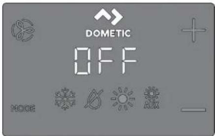
6/2 Display, 'atur's
This section eTplains the function of the icons on the capNouch display.
□
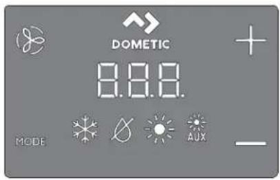
| Icon Na) * Function | ||
| ] an c cycles through the different | lan speeds. | |
| L ometic Brand identilication. | o oper-ational function. | |
| . p Raises the temperature set | point. | |
| L own | lowers the temperature set point. | |
| Ntemperature Indicator | L isplays the inside? set point outside? and water temperaturesf as selected. | |
 | Mode Indicator | Indicates the current display mode. |
 | ||
| MODE | k ' ' c Mode | b c cycles through the different modes.b Sends the display to sleep if held for three seconds. |
5 Sp' c i ications
The following table lists the cap/ouch control dimensions ^P cable lengths ^P system inputs ^P and operational specifications.
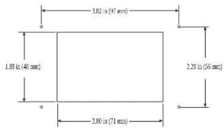
Pro( uct ( i) ' nsions
| Display Pan' | Di) 'nsions,or th' Eilon '4'1 | K.V into 1.9 in f0K.U mmlo ZU.XX mm2 |
| Cut-Out Di) 'nsions,or th' Eilon '4'1 | 0.9 | in'o | .| | in fK | .| X mmlo Z0.01 mm2 |
Cabl' l'ngth
| Insi( ' Air T') p' ratur' S' nsor :optional) | Z n fl .0U m2 Standard |
| OAT S' nsor :optional) | QV m FK.VZ ml Standard |
| All custo) cabl' l' ngths ar' suppli' ( in stan( ar( 5 ,t :1/52 ) ) incr') ' nts | ZV m fl | [ X m2 MaTimum |
A0ailabl'syst') inputs
| - at' r Inl' t T') p' ratur' S' nsor :C- Installations Only) | 0 |
| High R',rig' rant Pr' ssur' | 0 |
| Insi(' Air T'') p' ratur' S' nsor :optional) 0 | |
| Low R',rig' rant Pr' ssur' :optional) | 0 |
| OAT S' nsor :optional) | 0 |
| Pu) p S' ntry - at' r S' nsor :optional) :D8 Installations Only) | 0 |
| Roo) T') p' ratur' 3 R' lati0' Hu) i( ity Co) bination S' nsor :optional) | 0 |
Op' rational sp' ci, ications
| S'r Point Op' rating Rang' | VVJ p]lq 99.J p] f01.ZZpc lq UZ.I I pc |
| A) bi' nt T') p' ratur' Op' rating Rang' Display' ( | Vp]lq 0VJ -J p] f-0Vpc lq XV.VVpc h |
| S' nsor Accuracy | j | p]ir ZZol fj Opc r | Voc h |
| Low Voltag' Li) it 100 Vll... 120 V | 9V' ~ |
| Low Voltag' Li) it 200 Vll... 260 V | 09V' ~ |
| Low Voltag' Proc' ssor R's't | Vj' ~ |
| Uni0' rsal Lin' Voltag' | QJ J ' -# | KJ ' ~ |
| Fr' 9u' ncy | VJ k z or XJ k z |
| Fan Output | X 'Ir 0GV' ~ |
| X 'Ir | UJ ' ~ | |
| Val0' Output | V" r 0GV/ | UJ ' ~ |
| For C- Only: Auxiliary El' ctric H' at'r Output :using co) pr' ssor output L1 an( L2) | UJ ' MaTimum |
| Ext' rmal Triac | IX' |
| Ext' rmal 7-R' lay | UJ ' MaTimum |
| Pu) p Output | J.I V hp fJ .39 Y hr 0GV' ~ |
| J.V hp fJ .0Z Y ' r | UJ ' ~ | |
| Co) pr' ssor Output | Q hp fJ .7V Y fr 30V' ~I hp fQ.K9 Y hr | UJ ' ~ |
| A ini) u) Op' rating T') p' ratur' | p] fs | GZ.Z[ pch |
| A axi) u) A) bi' nt Op' rating T') p' ra-tur' | G| | p| fl | J | pc: |
| A axi) u) Rh Con( itions 99t ' on-condensing | |
| Pow'r Consu) ption u V Y |
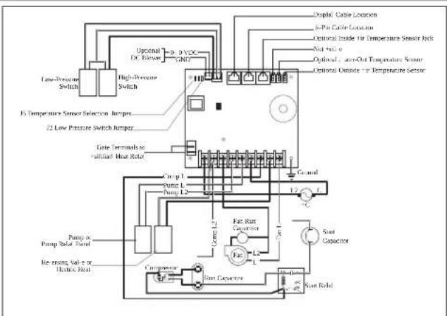
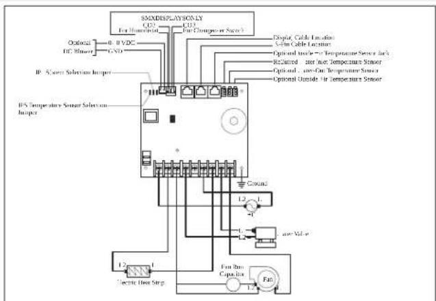
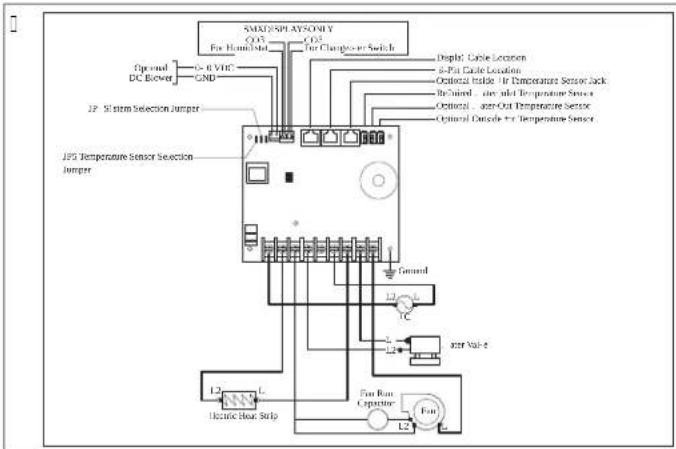
B - iring (iagra) s
This section provides eTamples of the L g and c Y Y iring for the capNouch controls.

- ARNIN! . ELECTRIC SHOCK HACARD/ Failur' to ob'y this warning coul( r' sult in ( 'ath or s' rious injury/ [urn power O]] before performing any electrical installation or maintenance activities.
D8 wiring (iagra)
「
flowchart
graph TD
    A["Low-Pressure Switch"] --> B["High-Pressure Switch"]
    B --> C["Up/Down /p. 3 VDC - GND"]
    C --> D["15 Temperature Sensor Selection Jumper"]
    C --> E["12 Low Pressure Switch Jumper"]
    D --> F["Low Terminals to +illified Heat Relay"]
    E --> F
    F --> G["Cump 1"]
    F --> H["Pump L"]
    F --> I["Pump L2"]
    G --> J["Fat Rint Capacitor"]
    H --> K["Fat"]
    I --> L["Fat"]
    J --> M["Sunt Capacitor"]
    K --> N["Sunt Radiol"]
    L --> O["Sunt Radiol"]
    M --> P["Sunt Radiol"]
    N --> Q["Sunt Radiol"]
C- wiring (iagra)
F
E Installation
This section describes the suitable location ^p preparation of the location and how to install a capNouch control.

- ARNIN! . ELECTRIC SHOCK HACARD/ Failur' to ob'y this warning coul( r' sult in ( 'ath or s'rious injury/ Num power O)] before performing any electrical installation or maintenance activities.

NOTICE. Failur' to ob'y th',ollowing notic's coul(r'sult in (a) ag'to th' pro(uct:
Lo not locate the display panel in direct sunlight ^2 near any heat-producing appliances ^3 or in a bull head where temperatures radiating from behind the panel may anect performance.
L o not mount the display in the supply-air stream or above or below a supply-air or return-air grille.
Lo not mount the display behind a door? in a corner under a stairwell or any place where there is no freely circulating air.
L o not staple sensor cables during installation.
L o not use a screw gun and do not overtighten the screws when mounting the display. Sither method may damage the display.

NOTE The display built-in temperature sensor is located in the control's display panel. 'n optional inside air temperature sensor is required i0 installing the display panel in a cabinet inside space or any area where the eTact sensing of the room temperature would be impaired.
E/1 Choosing a (isplay pan'1 location
Dlace the display panel in an area that meets the following location criteria:
b Mounted on an inside wall of the cabin away from direct sunlight.
b Sets slightly higher than mid-height of the cabin.
b located in an area of freely circulating air.
b Dlaced a maTimum distance of OV m fK.VZ m from the air conditioner.
E/2 Pr' paring th' wall
cut the cabin wall to 12 t the display panel to the bezel.
□
E/5 Installing an optional s' nsor
-
Mount the optional sensor according to the installation instructions included with the sensor.
-
Plug the sensor cable into the appropriate sensor jac on the upper side of the control board. Refer to the vY iring Liagrams in full manual for details on the sensor jac locations.
E/6 A ounting th' (isplay pan'1
- Dlug the display cable [-pin connector into the upper-right jac on the circuit board.
EN000
- Insert the other end of the display cable into the display jac on the bac of the display panel.
□
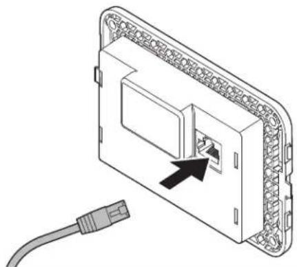
natural_image
Diagram of an electronic device showing a connector with an arrow pointing to a port, connected to a cable (no text or symbols present)U. . se the four screws provided to secure the display panel to the bull head. L o not use a screw gun or overtighten the screws.
K. Snap the bezel onto the display panel frame.
□
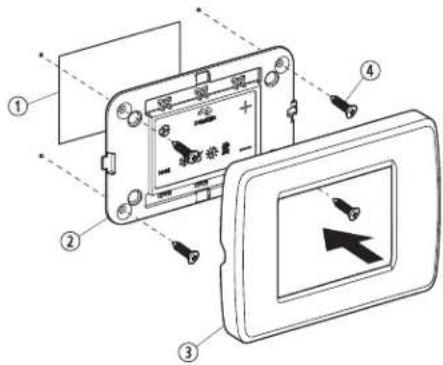
| Pos/ D' scription | |
| 1 cutout | |
| 2 L isplay Danel | |
| 3 Bezel | |
| 4 Screw |
E/5 T' sting th' (isplay
This section gives information on testing the display amer installation.

NOTICE. For D8 units only: ( o not turn th' circuit br' a1' r or pow' r suppli' ( to th' unit OFF an( th' n i) ) ' ( iat' ly turn it bac1 ON/ Failur' to ob' y this notic' coul( r' sult in ( a) ag' to th' pro( uct/ ' llow at least Ⅶve minutes for the refrigerant pressure to equalize.
-
Open the seawater-inta e ball valve fseacoc .
-
Nurn the display O]. Y ait a minimum of 0.5ve minutes.
U. Nurn the air conditioner circuit breaker O'.

NOTE 1: the seawater pump is on a separate circuit break be sure to turn it O'.
K. Rum the display O'.
V. Map the Fan icon.
X. 'erify that the fan is running and that a steady airxow is coming out of the supply-air grille.
Z. Select a temperature set point lower than the current cabin temperature.
[ . ' erily that a steady? solid stream of water is coming out from the overboard discharge.
- 'erily that a steady airxow continues to xow out of the supply-air grille.

NOTE 10 the unit is not functioning as eTpected\$ refer to vNroubleshootingy in Full manual.
F Op' ration
This section describes the cycle ^2 programming ^3 and functions for the capNouch controls.

NOTICE.. Cool-only units ( o not h' at unl' ss '9uipp' ( with auxiliary h' ating/ Failur' to ob' y this notic' will caus' th' unit to cool in both ) o('s/
If the unit is cool-onlyf change parameter D-OU to cIP then select ".NOM" Nlc mode.
Lo not set the unit to ".NOM" NiC mode before changing parameter D-CU to c1.
Refer to vSelecting a Darameters.

NOTE Y hen used with an optional auTiliary electric heaterf the fan remains O' for four minutes amer the heater cycles O]] even if the fan is set to cycled operation.

NOTE. The images in this section show the cap\ouch control display ^p unless otherwise indicated.
F/1 Un('rstan(ing th' h'ating an( cooling cycl's
Nhe heating and cooling cycles operate differently depending on the system installed. This section describes the possible cycles.
F/1/1 Nor) al h'ating or cooling cycl'
AUTOAATIC) o('
k eating and cooling are supplied as required to meet the cabin temperature set point.
Q. Nhe system starts a cooling cycle once the cabin temperature eTceeds the temperature set point by 1 p] f0 pch and starts a heating cycle once the cabin temperature falls below the temperature set point by 1 p] f0 pch. Nhe system continues the cycle until the cabin temperature equals the set point.
- During a cycle the cabin temperature must drop below the set point by at least K p] fl pc h before the system switches from cooling to heating or e'ceed the set point by at least K p] fl pc h before the system switches from heating to cooling. This behavior prevents small temperature overshoots from causing the system to switch between heating and cooling when it is not necessary.
Cool) o(
It supplies cooling only and k S" N mode supplies heating only.
- Mhe cabin temperature for either mode is maintained within [p] f0 pch of the set point by default.
[. Y hen the heating or cooling set point is satisfied ^b the compressor cycles O] and the fan returns to low speed.
A anual Fan A o( '
Nhe can speed remains constant.
F/1/2 Chill' ( -- at'r syst') op' ration :C- syst') s only)
In cY systems ^3 the water valve does not open unless the water temperature is adequate to heat or cool the cabin. The adequate heating or cooling water temperature is
defined by the water temperature differential setting in the control parameters. Refer to vSelecting a Parameter.
b Nap and hold Fan and Up simultaneously for three seconds ^2 to view the current water temperature.
b Refer to v. sing the control L isplay Danelw. The can remains on low speed until the adequate water temperature is available.

NOTE No give heat when the required water temperature is not available; install the optional auxiliary electric heater and program parameter D-I [ . Refer to vDrogramming the controlw.
F/1/5 R'0' rsing-0al0' op' ration :D8 syst') s only)
c OOI mode or k S" N mode is determined by the position of the reversing valve. Nhe reversing valve is programmed to automatically toggle in these situations
b Y hen the system is running and an opposite cycle is needed to maintain the temperature? the reversing valve will toggle to the opposite position to start the opposite cycle and reduce the starting surge of the compressor.
b Y hen a cooling or heating cycle is initiated amer the system has been O] for less than five minutes.
b Y hen a cycle is interrupted by changing the display mode to O] or changing the set point from the display panel.
b No reduce reversing-valve noise unnecessary valve toggling is limited by default. Drogram the minimum compressor staging delay fparameter D-U to live minutes or greater to end valve toggling. Refer to vDrogramming the control.

NOTE Y hen the system is powered upf a power-on-reset always initiates a valve toggle.
F/1/6 D'-icing cycl':D8 syst') s only)
L g systems have a de-icing cycle option to prevent ice buildup on the evaporator coil during eI tended periods of cooling operation. Installation variables ^2 such as grille sizes ^2 length o ^3 ducting ^2 insulation ^2 and ambient temperatures ^2 decide the runtime required to achieve the set point.
] actors that substantially increase the runtime include operating the system with hatches and doors open and programming an unrealistic set point e.g. XVβ] fQ[ .UUacA]. Such situations can cause the evaporator to form ice on warm humid days.
L e-icing is accomplished by closely monitoring the room air temperature in CJ min intervals during a cooling cycle. L epending on the parameter value and the change in room temperature during these monitoring intervals? the control performs various actions to prevent ice from forming or to melt ice that has already formed. This is accomplished by short compressor shutdown periods combined with a one-speed increase in the can speed? and by periodic k S' N mode cycles with the can turned on.
Nhe de-icing cycle algorithm initiates periodic compressor shutdowns every QJ min if the inside temperature is at or below X9pJ H J .VXpcJ. Nhe lower the temperature ^2 the longer the compressor shutdown will last. In addition, the de-icing cycle algorithm will perform brief reverse cycle runs with the an purposely turned on if the cooling cycle runs for KJ min without any cooling progress or if the cooling cycle runs for more than XJ min ^2 regardless of cooling progress.
The parameter setting for the de-icing feature depends on whether you are using the optional inside air temperature sensor or the display built-in temperature sensor. Installation of an optional inside air temperature sensor located in the return air path greatly increases the erectiveness of the de-icing feature and this option should be considered whenever the display sensor cannot read the room temperature accurately.
] or more details on parameter settings and navigation options\$ refer to vSelecting a Parameterw and see Null manual for v' avigation Nreen.
F/2 Choosing th' control op' ration
The Cour Mode indicators represent the dinerent modes of the control c OOLP L Sk . MIL I] Ic "NIO' P k S" NP and ". g k S" N. Refer to va for more detail on mode operation.
- Nap the Mode icon to select a mode.
Refer tov' vailable Modes and Options for Operations,
- L isplay icons illuminate to indicate the selected mode.
Nhe display loc s into the last mode selected arer wve seconds of inactivity? then displays the room temperature. Nhe selected mode |SL remains lit.
* mer Q; seconds of inactivity; the display shows the room temperature and enters the IL15 state.
O]] displays on the screen to indicate the O]] state.
Y hen the display is ma ing a call for heating ^p cooling ^p auT heat ^p or humidity ^p the appropriate Mode indicator blin s for two seconds O' and two seconds O] ].
. Nap any icon to wave up the control from the O] or IL |S state.
U. Nap and hold the Mode icon for three seconds to start a SI SSD state.
√ The display goes dar .
'ormal operation continues.
K. Map and hold the Mode icon for three more seconds to wave up the control.
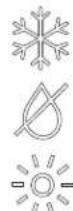
F/2/1 A0ailabl' ) o('s an(options,or op'ration
| Icon A o( ' an( Function | |
 | Nhe c OOL mode icon illuminates when the c OOL mode is se-lected or when the unit is in an '. NOM" Nlc mode cooling cy-cle. Only the cooling system operates. If the ambient tempera-ture drops below the set point ^1 the system will not automatically switch to the k S" N mode. |
EN0000
| Icon A o( ' an( Function | |
| Nhe L Sk . MIL I] Ic " NIO' mode icon illuminates when the L S- k . MIL I] Ic " NIO' mode is selected. This mode controls humid- ity during periods when the vessel is unoccupied and prevents the cabin temperature from dropping below the minimum default temperature setting. During hu) i( ity control:b The fan circulates air for UJ min.b 'ir temperature is sampled and recorded.b 'ter UJ min? a cooling cycle starts and continues until the tem-perature is lowered [ p] f0 pc or until the cooling cycle runs a maTimum of one hour.b our hours after the temperature is satisfied or the cooling cy-cle times outf the cycle repeats.For t') p' ratur' control:b 'ter the UJ min fan circulation? if the sampled temperature is at or above the factory default setting VJ p| f0j pc iP a cooling cycle begins and runs for humidity control.b I0 the temperature is below VJ p] f0j pc iP a heating cycle be- gins. Nhe heating cycle continues until the temperature reach- es VJ p] f0j pc or until the heating cycle runs a maTimum of one hour.b our hours after the temperature is satisfied or the cool- ing/heating cycle times outf the cycle repeats each time de-termining whether cooling or heating is required. | |
| NOTE ] or L g systems only: the L Sk . MIL I]I- c ' NIO' mode heat cycle will not run when the am- bient temperature is below KJ p] fK.KKpc :. This pro- tects the condenser coil from freezing. Systems con- grouped with electric heat will run the L Sk . MIL I] I- c ' NIO' mode heat cycle regardless of the cabin temperature. | |
| Nhe k S' N mode icon illuminates when the k S' N mode is select- ed or when the unit is in an ". NOM" Nlc mode heating cycle. Only the heating system operates. E the ambient temperature ris- es above the set pointf the system will not automatically switch to the c OOL mode. | |
| Nhe *. g k S' N mode icon illuminates when the optional auTiliary electric heater is in operation. I0 the ambient temperature rises above the set pointf the system will not automatically switch to the c OOL mode. | |
| OFF | O]] mode icon. " ll control outputs are turned OI ]. Nhe display reads OI], ' ll settings are saved in non-volatile memory. |
| 680 | O' mode icon. " ll control outputs are on and the display indi- cates the current state of operation. Nhe display shows the cabin temperature. " ll parameters operate as set. |
| Nhe ". NOM" Nlc mode icons illuminate when the system is in ". NOM" Nlc mode? which switches to cooling or heating as re- quired to satisfy the temperature set-point. Y ben ". NOM" Nlc mode is selectedf the system provides both heating and coolingas required. Nhe c OOL and k S' N indicators or c OOL and '. g k S' N icons are illuminated according to the ". NOM" Nlc mode. |
| Icon Ao( ' an( Function | |
| Nhe Fan icon allows the user to cycle through all of the different fan speedsf which include auto and CsV fZ low2 l z medium low3 Uz mediumf Kz medium high2 and Vz high'. I am speeds are automatic based on default and programmed values. Drogram menu settings D-G and D-I decide the maximum and minimum can speed settings.b ] an speed decreases as the temperature set-point is approached in c OOL mode and operates at low speed when the set point is reached.b Nhe automatic can speed operation can be reversed for k S' N mode when parameter D-OI is set to vrS] κ. See vDrogramming the c control for more detail.b "utomatic can mode determines the required can speed based on temperature differential. This balances the most efficient temperature control with a slower6 quieter can speed. No select automatic can mode3 tap and release the Fan icon until an v" n appears on the display. | |
| NOTE. Refer to vSelecting a Parameterx. Once high and low can speed limits are set2 the unit automatically readjusts the remaining can speeds in both automatic and manual can modes. | |
| Manual ] an allows the selection of a consistent desired can speed. Where are we manual can speeds available: high/medium high/medium? medium lowf and low. The speed number is illuminated on the display when selected.b Nap and release the Fan icon to advance from automatic to manual can operation.b Nap and release the Fan icon to cycle through the manual can speedsf from low to high.b Nap and release the Fan icon to return to automatic can operation. | |
| - se | an-Only to operate the can for air circulation when no cooling or heating is desired.C. | rom the OJ] mode3 tap and release the Fan icon to select a desired can speed. | |
| NOTE. Burning the control O' reverts the can to the ". NOM' NIC mode or the last selected manual can setting. | |
| cycled / c continuous ] an modeNhe can can be set to run continuously whenever the system is turned O' F or it can be set to cycle O' and OJ] in conjunction with the cooling or heating cycles.C. Nap and hold the Fan icon for 5ve seconds.c ec displays when the operational setting is set to cycled.c O' displays when the operational setting is set to continuous. |
F/5 Using th' control (isplay pan'1
The following table details the icon combinations to use to activate dinerent functions on the control.
| Icon Co) bination Icon Na)'s an( | Function |
| MODE 4 | Mode & UpSnter the programming menuQ. Nap simultaneously and hold for three seconds while the control is in the O|| mode.DQ appears on the display. |
| 4 | Up & DownL isplay the outdoor temperature:Q. Nap simultaneously and hold for three seconds.Nhe display alternates between O. and the outdoor temperature reading while this combination is held. |
| Icon Co) bination Icon Na)'s an( Function | |
| Fan & UpL isplay the seawater temperatureD. Nap simultaneously and hold for three seconds.Nhe display alternates between SS and the seawater temperature reading while this combination is held. | |
| Up Down' & ModeL isplay the relative humidityO. Nap simultaneously and hold for three seconds.Nhe display alternates between k S and the relative humidity reading while this combination is held. | |
| MODE 4 | Mode & DownSenter fault historyO. Nap simultaneously and hold for three seconds while the control is in the O)] mode to enter the fault history log.Nhe display holds up to eight faults.I...se the Up and Down icons to view the fault history.U. Nap and hold the Mode and Down icons simultaneously for three seconds to clear the fault history.K. STit by tapping the Mode icon once. |
| Fan & DownLg Onlye display the compressor run-time hour metersO. Nap simultaneously and hold for three seconds while the control is in the O)] mode.Nhe display will show the code k r one time and then shows the run time.I. STit by tapping the Mode icon once. D-I low I an | |
F/6 Progra) ) ing th' control

NOTE I' your "c has a Shaded-Dole fSDh can motor instead of a Split-capacitor fSc k igh-' elocity fk ' h tan motor? program SD into the can motor type parameter before operating the unit. Refer to vProgramming the control. SD units are recognizable by an overhanging blower motor. The Sc motor of an k ' unit is inside the blowerf and the unit has ' NL or k ' as part of the model number. Only reprogram the can motor type parameter if you do not have an k ' blower.
Parameter settings are used to program and wine-tune the system for the most efficient operation within an installation and to adjust operating parameters for your particular needs. "mer new values are entered and memorized? the factory defaults are overwritten and the new parameters become the default values.
Should the cap/houch lose power ^2 the operating parameters are retained. Y hen power is restored ^3 the control resumes operating as last programmed.
The control has factory default values stored in permanent memory fmemorized factory default settings that can be recalled if you have any programming difficulties. You can restore the original factory default parameters manually. Refer to vSelecting a Parameter for a summary of the parameters? the permitted values and original factory default settings.
F/6/1 Ent' ring progra) ing) o('
This section gives step by step instructions for entering programming mode.
C. Y hile the control is in the O] mode ^2 simultaneously tap and hold the Mode and Up f+h icons on the display screen for one second to enter the programming menu. D-O appears on the display.
□
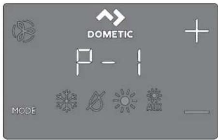
- . , se the Up f+h and Down f-h icons to navigate to dinerent parameters FD-CF D-I 2D-UF etc.h.
U. Nap the Mode icon to enter the parameter adjustment menu.
√ The display will alternate between the parameter number and the current setting.
K. Nap the Up f+h and Down f- icons to adjust the parameter settings.
V. Nap the Mode icon to loc in the parameter change and return to the programming menu.
F/6/2 S' l' cting a para) 't'r
The following table describes the parameters available for the capNouch controls.
| Para) 't'r Na) 'D8 C- Factory D'- | Para) 't'r Rang',ault | |||
| x x 9V XVs9VD-0 kigh ] an | imit | ||||
| Select a higher number to increase the can speed? a lower num-ber to decrease the can speed. | ||||
| mit | x x V] U| sZV | |||
| Select a higher number to increase the can speed? a lower num-ber to decrease the can speed. | ||||
| D-U | compressor Staging Nime L elay | x | QV V siq UV s | |
| se for installations where more than one system operates from the same power source. L i'ferent staging delays allow compressors to start at different times when the power is interrupted. Stage the units at least five seconds apart. | ||||
| D-K | Inside "ir Nemperature Sensor c ali-bration | x x *mbient Ntemperature p] IX pc: | ||
| calibrates the sensor to display the correct room temperature reading. The setting increments are in p] even when the control is set to display pc. | ||||
| D-V | Jailsale level | x | U J z Minimal DrotectionC z continuous ' o l isplayI z continuous Y ith L is-playU z J our Jailures? Reset Re-quired | |
| Refer to v| all Sale levels. | ||||
| NOTE. Parameter Range G and I applies to display Wrmware #40 and older. | ||||
| D-X | low 'oltage Monitor | x x | O|| O] P 9V' ~X9V' ~ | |
| Set the built-in voltmeter circuit that monitors the *c input volt-age prior to each cooling or heating cycle when set to 9V' ~or Q9V' ~b [or Q] ' ~q Q] ' ~ input power? set to O] or 9V.b ] or I[ ' ~q I K] ' ~ input power? set to O] or Q9V. | ||||
EN000
| Para) 't'r Na) 'D8 C- Factory D'- | Para) 't'r Rang',ault | ||
| D-Z L e-icing c y-cle | x O]] | O||0 z O' with V p] fU pc: L is-play Sensor L I'erential1 z O' with Z p] fK pc: L is-play Sensor L I'erential | |
| Select the parameter setting for the de-icing feature depending on whether you are using the optional inside air temperature sensor or the display built-in temperature sensor.b D using an optional inside air temperature sensor set this parameter to 3 to turn the de-icing feature O' for to O[] to disable.b D using the display built-in temperature sensor choose one of the two selectable behavior modes.0. ' assumes the display sensor may be reading the room temperature as much as V a] fU pc: greater than the actual evaporator temperature fstandardh.1. | or more e l'treme installations - assumes the display sensor may be reading the room temperature as much as Z p] fK pc: greater than the actual evaporator temperature.b Nhe setting o#l should only be used if a setting o# does not prevent evaporator ice from forming. | |||
| D-[ OptionalDump Sentry | x O]] | O]]O' z Select QJ J J p| qGVJ J a| fUZ.ZZpc iqXV.VVac II | |
| Set this parameter setting when the optional pump sentry water sensor is installed to check the condenser coil temperature and to shut down the pump and compressor when the coil temperature rises above the programmed value. His sensor is plugged into the k I O O. N sensor jac on the control board.Drogram a temperature between QJ J J a| q GVJ J a| fUZ.ZZpc iqXV.WVpc I P depending on seawater temperature and the system type. Refer to the sensor installation instructions. Nhe setting increments are in p] even when the control is set to display pc. | |||
| Brightnessc control | x x U O fL immesdis U fBrightestID-9 L isplay | ||
| Set this parameter setting between C and U. ' dar cabin requires a setting of C. ' very bright cabin requires a setting of U. | |||
| D-OJ ] ahrenheit orc elsius Selec-tion | x x ] | ] z ] ahrenheit L isplayedc z c elsius L isplayed" z " utomatic Selection Based on 'oltageV] k z z c elsiusX] k z z | ahrenheit | |
| Select pc for c elsius fc elsius readings are displayed in tenths2 for eTample III.1 ph. Nhe default setting is p]. | |||
| D-50 | cycle Dumpwith c om-pressor | x | cec c cc z cycle with c om-pressorcon z c continuous Dump |
| Select cycled or continuous pump operation.b c eca increases the pump life and conserves electricity by cy-cling O' and O[] with the compressor.b c ona programs the pump to operate continuously whenever the system is on. | |||
| D-OI Reverse 'u-tomatic ] anSpeeds L ur-ing keating | x x nOr | nOr z ' normal ] an Opera-tionrS| z Reversed ] an in k S" V Mode | |
| Para) 't'r Na) 'D8 C- | Factory D'- | Para) 't'r Rang'ault |
| Reverse the automatic fan speeds during k S' N mode to improve heat output in cooler climates.b Y hen set to rS]F the fan speeds up as the set point is approached. The fan switches to low speed when the set point is satisfied and the water valve or compressor cycles O| | .b Y hen set to nOrf the fan operates the same as during coolingf which represents normal fan operation. | ||
| D-0U cool-Only Mode | x | k D k D z k eat Dumpcl z cool-Only |
| Select heat pump or cool-only operation.b Selectingvk Do operates the unit in the default heat pump model which allows for coolingp reverse cycle heatingp or foptional: auTiliary electric heat.b Selecting vc lw operates the unit in c OOl or foptionall * . g k S" N modes.b * . g k S" N mode is only available if the unit is equipped with an auTiliary electric heater. | ||
| NOTE Selecting vc lw initiates a five-minute compressor delay when the compressor shuts down on the set pointf a fault or a power outage. The five-minute delay begins immediately after the compressor shuts down. The c OOl mode icon on the display clashes once per second for five minutes or for the remaining time to complete the five minutes after the last cycle end time. If the five-minute delay period has passed before the compressor is called to operate# the compressor comes on with no delay. | ||
| D-GK ] an Motor Selection | xx Sc | Sc z Split capacitor | an MotorSD z Shaded Dole ] an Motor |
| Set to Sc for "c switch high-velocity blowers. Set to SD iD your unit has a Shaded Dole fan motor. Refer to vProgramming the controls. | ||
| D-GV Restore ] acto-ry L eault Set-tings | xx nOr | rSh z Reset LeaultsnOr z 'ormal |
| No reset all programming parametersset this parameter to rSN.This restores all programmable parameters to the factory default values. | ||
| D-OX ky dronicY ater 'alve]orced Open | x | nOr OOn z 'alve ] orced OpennOr z 'ormal Operation |
| Open the water valve to bleed air from the system.b OOn forces the valve open for four hours while the control is turned O| | . If the control is turned O' or if "c power is inter-rupted during this four-hour period the valve override is canceled.b nOra returns the valve to normal operation. | ||
| D-OZ | Y ater Nem-perature L iR-erential | x GV p] f [ pc h V p] to | V p] fUs c to OK och |
| Set the temperature differential between the ambient air temper-ature and the hydronic water temperature that controls the water valve. | or eTample# selecting Oj p] fs Cl .1 | pc r opens the valve when the water temperature is Oj p] fs Cl .1 | pc h less than the ambient temperature in the cooling mode and Oj p] fs Cl .1 | pc h greater than the ambient temperature in the heating mode.c areul selection of the temperature differential can fully use the ship's heating and cooling resources. | or eTample# while in cooling mode and using a Oj p] fs Cl .1 | pc h value the valve will open to allow some cooling while the hydronic system is coming down to temperature. | ||
| Para) 't'r Na) 'D8 C- Factory D'- Para) 't'r Rang'ault | ||
| D-C[ 'ir]ilterc leaning/ ReplacementNimer Setting | x x ] L isplays the elapsed timefin hours TQ] since the timer was started or reset. | |
| S establish a reminder to clean or replace the air filter. Ar/FL flashes briefly on the |SL display every Q] seconds until it is cleared.b Nhe parameter entered represents that number times Qj hours. Select the number of operating hours until the filter reminder appears.b Parameter choices are between QJ [QJ] hours and |VJ |VJ| hours'.b Nap the Down icon to reset the value to |P restart the timerl and clear the reminder. | ||
| NOTE L ometic recommends checking the air filter at least every VJ | hours of operation. | ||
| D-09 |ilter c leaning/ Replacement Nimer value & Reset | x x ] L isplays the elapsed timefin hours TQ] since the timer was started or reset. | |
| L isplay the current elapsed time fin hours TQ] since the timer was started or reset. Y hen this parameter value reaches the value set in parameter D-QJ |Ar/FL clashes on the display every Qj seconds until cleared. Nap the Down icon to reset the value to J P restart the timer2 and clear the reminder. | ||
| x x dIS f. nit ILz V9 falter enabling and power cy-clingl | |sl VVD-I |c'' Bus . nit z V9 falter enabling and power cy-clingl | |
| Snables all units with a c'' Bus adapter installed to be net-wor ed together and communicate with each other or the ship's c'' Bus system with more translator equipment in some cases.h No enable the functionality? set the parameter to j . b 'llow the display to revert to O] mode.b Dower cycle the system.b Once the system powers on the c'' Bus . nit IL will be set to V9.b Enter the unit's c'' Bus . nit IL number. | ||
| x x V[ falter en-abling and power cy-clingl | ] sl VVD-I 0c'' Bus | |
| Snables all units with a c'' Bus adapter installed to be grouped together in a network system and communicate with the ship's c'' Bus system with more translator equipment in some cases.h Y hen parameter D-I ] is disabled? the Mroup IL displays Q.b Once the c'' Bus . nit IL is set to j and the power is cycledf the c'' Bus Mroup IL defaults to V[ .b c complete the steps in parameter D-I ] ? then enter the unit's c'' Bus Mroup IL number. | ||
| D-I I 'oltage cali-bration | x x 'c 'oltage"djust to match the eTact voltage reading. | |
| L isplays a live reading of the voltage being read by the circuit board. c calibrating this parameter provides a more eTact voltage level when calculating low voltage for parameter D-X. . se a reli-able voltmeter during adjustment. | ||
| D-I U Set Doint Temperature L i'erential | x x l | Q z Q p] fj .X pch L i'erential l z Q p] lg pc+ L i'erential |
| Set the temperature di'erential in ] ahrenheit for all modes of operations". NOM" Mt F c OOLF k S" NF or ". g k S" N. Recler to vc hoosing the control Operations.b Cs maintains the room temperature j Q p] ll .X pch from the desired set point.b I s maintains the room temperature j | p | fo pc h from the desired set point. | ||
| Para) 't'r Na)' D8 C- Factory D'- | Para)' t'r Rang'ault | ||
| D-I K L Sk . MIL I]I-c'' NIO'Mode Mini-mum Neme-pature | x x Vj p] fQ pc h Kj J o] iq ZVj p]____Set the minimum room temperature fin ]ahrenheit for which L Sk . MIL I] Ic'' NIO' mode initiates a cooling cycle to remove moisture from the air. D the room temperature is below this para-meter settingf L Sk . MIL I] Ic'' NIO' mode runs a heating cycle.Reer to vc hoosing the c control Operationw. | ||
| D-I V' uto | anSpeed Neme-perature L i-terential | x x | | p] fQ pc h Qp] to U p] fj . X pc to l pc h | |
| Set the incremental di'erential (with cumulative steps) between the ambient temperature and the set point temperature at which the fan speed will increment to the neTt speed. | |||
| NOTE '' Qp| fj . X och hysteresis in the auto fan speed di'erential prevents the speed from changing if the room temperature changes. In addition2 programming parameters D-0l and D-1 U both have an effect on the operation of the auto fan speed. | |||
| D-I X Supply "irk igh Neme-pature limit | x x O] | O] ]9Vo] lq QK j p] in V p incre-mentsfUVpc iq Xj pc in l J p in-crementsh | |
| Set the maTimum supply air-discharge temperature allowed.b Snabling this parameter has no effect unless parameter D-I [ is enabled and set to Sn",b . se of this parameter requires that the O' N sensor be placed in the supply air stream immediately downstream of the blow-er discharge.b k S' N mode shuts down if the temperature of this sensor et-ceeds the setting, k S' N mode is restored when a 0j p] fX pc h hysteresis is satisfied or when power is cycled to the control and the O' N sensor temperature is less than the setting but still within the hysteresis. S" k is displayed when this fault occurs.b L isplay the discharge temperature by tapping the Up andDown icons simultaneously 'same as viewing the outside air temperature'. | |||
| D-I Z Idle State L e-lay | x x | 0j seconds Vs lq 0j s fv s incre-mentsh | |
| Set the delay time before the display enters an idle state. Refer to vc hoosing the c control Operations.. se theUpor Downicons to increase or decrease the idle delay time. | |||
| D-I [ ' uTiliary k earSnable | x x | dIS dIS/Sn' | |
| Snable the operation of an optional auxiliary electric heater. If an auxiliary electric heater is installed? change this setting to Sn' to allow the auxiliary electric heater to be operated independently of the reverse-cycle heating. In L g applications' the auxiliary elec-tric heat and compressor outputs on the control board operate at the same time only when the dehumidification functionality is active. Refer to vRelative k umidity Snables in this table. | |||
EN000
| Para) 't'r Na) 'D8 C- Factory D' - | Para) 't'r Rang'ault | ||
| midity Snable | x x O] ] O] ] /V] s[ ] D-19 Relative k u- | ||
| Snable the optional room temperature/relative humidity combination sensor. Nhis allows the system to dehumidily using auTiliary electric heat fiE an autilary electric heater is installed and enabled when the cabin humidity rises above the selected relative humidity fRk h.b] or L g applications: Relative humidity enabled. If the optional room temperature/relative humidity combination sensor is connected to the control board and senses that the humidity has increasedf the compressor run time will eTtend by operating to Gp] fsOZ.I | pc h lower than the set point to remove the humidity. If an autilary electric heater is installedf it will cycle O' and O] ] to maintain the set point while the compressor stays on longer to dehumidily. | |||
| [SDCY]NOTE There could be a period o' overlap when the compressor and the autilary electric heater are on at the same time. Nhis cycle continues until the cabin's relative humidity is less than the humidity set point. Nhe range o' adjustment for the relative humidity is V] t q [ ] t Rk.d] or c Y applications: Relative humidity enabled. If the room temperature/relative humidity combination sensor is connected to the control boardf this feature allows the system to dehumidily with electric heat fiU an autilary electric heater is installed and enabled when the cabin humidity rises above the humidity set point. Nhe autilary electric heater will cycle O' and O] ] to maintain the set point while the bypass valve opens to allow cold loop water to enter the air handler coil to dehumidily. Nhis operation continues until the cabin's relative humidity is less than the humidity set point. If an autilary electric heater is not installedf the on time of the bypass valve will eTtend by operating to Gp] fsOZ.I | pc h lower than the set point. Nhis cycle continues until the cabin's relative humidity is less than the humidity set point. Nhe range o' adjustment for the relative humidity is V] t q [ ] t Rk. | |||
| D-UJ Seawaterlow-limit 'd-justment | x Kj a] | UV,j p] lq Vj a] fo.XXpc qfk.KKpc 1 Qj pc' | |
| If the optional seawater low-limit adjustment sensor is connected to the control board k I O Out I -pin plug? set the system to switch from reverse-cycle heat to autilary electric heat fiU an autilary electric heater is installed and enabled.b' djustment occurs when the seawater temperature drops below Kj p]fk.KKpc h and the reverse-cycle heat has been in operation for more than we minutes. Once the seawater rises Uo] fsOX.GQpc h above the seawater low-limit adjustment sensor temperature set point? the system returns to reverse-cycle heating.b If an autilary electric heater is not installed? the system will shut down and xash LO then SE when the seawater drops below Kj p]fk.KKpc h default. Once the seawater rises Up] fsOX.GQpc h above the seawater lowlimit adjustment sensor temperature set point? the system automatically goes bac into reverse-cycle heating and stops clashing LO then SE. | |||
| D-UO k umidity Sensor calibration | x x 'mbient | "mbient Relative k umidityRelative j QJ tk umidity | |
| calibrate the room temperature/relative humidity combination sensor to display the correct room humidity reading. | |||
| NOTE Nhis setting is applicable to software revision #KI and newer only. | |||
| D-UI Y ater InletNtemperatureSensor calibration | x x | cY z Supplied c hilledY ater NemperatureLg z condenser coil orSeawater Nemperature j Qj Qj FX pc h | |
| Para) 't'r Na) 'D8 C- | Factory D'- | Para) 't'r Rang'ault | |
| calibrate the Y ater Out fl g/ or Y ater In fc Y h temperature sen-sor to display the correct water temperature reading, khe setting increments are in p| even when the control is set to display pc. | |||
| NOTE khis setting is applicable to software revision #KI and newer only. | |||
| D-JU O' N Sensor calibration | x x Outside ' m- | Outside ' mbient Nempera-ture j 0j p] fX pc t | |
| bient Nem-perature | |||
| calibrate the outside ambient air temperature sensor to display the correct outside air temperature reading, khe setting incre-ments are in o| even when the control is set to display pc. | |||
| NOTE khis setting is applicable to software revision #KI and newer only. | |||
F/6/5 Exiting progra) ing) o('
This section gives information on how to eTit programming mode.
No eTit the programming menu manually ^2 simultaneously tap and hold the Up f++ and Mode icons for three seconds until the room temperature is displayed.
"Internatively the display automatically eTits the programming menu amer 0j seconds of inactivity.
√ Nhe control's software version f such as vKJ w appears in the display for one second prior to the manual or automatic eTit from the programming mode. Nhe control enters O]] mode ander eTit.
F/6/6 I('nti,ying progra) ing ,ault co('s
□
No protect the unitf certain fault conditions trigger a loc out that shuts down the control. The control will not restart until the fault is repaired. The type o1 loc out associated with the fault depends on the type of fault detected freer to the ]ault and Status codes table below in combination with the level o2 protection freer to the ]all Safe levels table below that was programmed in the D-V parameter freer towSelecting a Carameterwh.
Fault an( status co( 's
| Co(‘D’scription D8 C- | ||
| k D] | k igh Dressure Switch ] aulta indicates high refrigerant pressure. Nhis fault is not applicable in k S' N mode. | x |
| ID] | I ow Dressure Switch ] aulta indicates low refrigerant pressure. Nhis fault has a three minute shutdown delay for display Wmware #41 and newerh. | x |
| DI] | I ow Dump ] low ] aulta indicates high-water temperature in the condensing coil or low pump xow. | x |
| II /- - | Indicates a loop water sensor failure. | x |
| Co( ' D' scription D8 C- | ||
| IS/– - Inside Sensora indicates the display built-in temperature sensor is damaged. | x | x |
| " r/|| Indicates the air filter replacement timer has eTpired. | x | x |
| S'' k Indicates a high supply air temperature lim- it. | x | x |
| S|D Indicates Sleep or loc mode. Buttons do not function in these modes. | x | x |
| |O/SS Indicates a seawater low limit. x x | ||
| |O/'c |ow ' oltage ] aulta indicates low voltage.This fault offers eTtra protection for the compressor and components within the system during low-voltage brownouth conditionsb "ter the compressor starts? the low volt-age monitor checs the ' c input vol-tage. E voltage drops below the speci-tied setting f9V ' -49V ' and re-mains below for three minutes? the sys-tem shuts down and the low " c voltage fault displays.b Nhe fault continues until the ' c input voltage rises above 9V ' -49V ' . ~Nhen? the | O/' c fault code clears auto-matically and the cooling or heating cy-cle commences. | x | x |
Fail sa,' l' 0' ls
| L01 D' scription | D8 Only | |
| J | |ail Safe level J: Temporary Tailsale ^2 limited to 1ve-minutes. Nhe system will automatically switch bac to Level U after 1ve minutes fonly in display Wrmware #KQ and new-ent. Provides minimal Tailsale protection and is not recommended.b Only the IS/— - fault is detected and displayed.b Nhe control shuts down and will not restart until the fault is repaired.b Once repaired? the control restarts after a two-minute delay. | x |
| Q | |ail Safe level Q fonly for display Wrmware #K| and old-erns includes the Tailsale actions of the earlier level and detects all other faults? but they are not displayed.b Nhe system shuts down for two minutes or until the fault is cleared whichever is longer.b Nhe system restarts when the fault is cleared. | |
| I | |ail Safe level I fonly in display Wrmware #K| and olderle includes the Tailsale actions of the earlier levels and dis-plays all other faults.b Nhe system shuts down for two minutes or until the fault is cleared whichever is longer.b Nhe system restarts when the fault is cleared. | |
| U | |ail Safe level Ua includes the Tailsale actions of previous levels and the system will loc out after our consecutive k D[F[D] or O[I]] faults. In addition? the loc out can be cleared.b Nhe system shuts down for two minutes or until the fault is cleared whichever is longer.b No clear the loc outEnter O[I] mode. Nhenif return to O’ mode. |
G NaOigation tr'
This section shows the menu navigation for the capNouch control.
10 Troubl' shooting
The following table describes some common occurrences that are not a result of defective wormanship or materials.
| Probl*) Possibl' Caus's R' co) ) 'n' ( Solution | ||
| Nhe system does not power up. | Nhe air conditioner circuit brea er is on. | Nurn on the air conditioner circuit brea er at the ship's panel. |
| Nhe display is not turned on. | Nurn on the display. | |
| Nhe terminal strip is mis-wired. | c hec the wiring diagram and correct if necessary. | |
| Nhe input-line voltage is in-sufficient. | b c hec the power source shore/alter-nator for proper voltage.b c hec the wiring and terminals for proper sizes and connections.b ̈ erily with a volmeter that the pow-er at the unit is the same as the power source. | |
| 'n electrical part has failed. | * technician should inspect the display2 cable and circuit board. Too for a red light on the circuit board. | |
| Nhe system runs con-tinuously. | Nhe unit is not able to reach the set point. | c lose all the terminal holes and hatches.* adjust the set point so it is not too low for cooling or too high for heating. |
| Nhe seawater temperature is too high for cooling or too low for heating. | Seawater temperature will directly a-ject the air conditioner's efficiency. This air conditioner can effectively cool your boat in water temperatures up to 9j p] full J I pc and heat fi reverse-cycle option is installed in water as low as Kj p] fK.KKpc. | |
| Nhe optional inside air tem-perature sensor is not loca-ted properly. | b ̈ erily the display location with the cri-teria bound in the installation section of this manual.b Install an optional inside air tempera-ture sensor is necessary. In an option-al inside air temperature sensor is al-ready installed in the air stream ensure it does not touch anything warm fli e the condenser coil. | |
| Nhe de-icing feature is not enabled. | Snable de-icing in the parameters. E ice still forms immediately revisit the above possible causes. | |
| NOTE Ice on a fan coil can be removed quickly by run-ning the unit in heat mode. | ||
| There is a lac of air-flow. | Nhe air-low is bloc ed or re-stricted. | b Remove any obstructions in the re-turn-air stream.b c lean the return-air filter and grille.b c hec for crushed or restricted duct-ing. L ucting must be as straight smooth and laut as possible. |
| Nhe fan speed is set to man-ual low. | b E the fan speed is set to manual low? raise the speed to a higher setting or set to automatic mode.b Or increase the minimum low speed in the program parameters. | |
| Nhe fan coil may be iced. | Refer to vNhe fan coil is iced in this table. | |
| Nhe fan coil is iced. | Nhe humidity level is set too high. | c lose the hatches and doors. |
| Nhe supply air is short-cy-cling. | b Redirect the supply air so that is not blowing in or near the return-air stream.b Seal any air lea s on the duct. | |
| Nhe airflow is bloc ed or re-stricted. | Refer to vWhere is a lac of airflow in this table. | |
| Probl' ) Possibl' Caus' s R' co) ) ' n( '( Solution | ||
| Nhe fan runs too slow. | Set the fan speed to automatic mode or increase the manual fan speed. Orf increase the minimum low speed in the program parameters. | |
| Nhe system runs continuously. | c lose hatches and doors? raise set pointf turn on de-icing. | |
| Nhe condenser coil is iced while in hear mode. | Nhe seawater temperature is below Kj p] fK.KKpch. | b Shut down the system to prevent dam-age to the condenser.b *llow the coil to derost. |
| Nhe fan does not run or runs continuously. | Nhe digital control is set for either fan cycling with compressor or for continuous fan operation. | c change the fan operation to continuous fan operation or fan cycling with compressor. i NOTE Y hen configured for auxiliary electric heat the fan will stay on for four minutes after a heat cycle ends even if the fan is set to cycled operation. |
| Nhe circuit board on the unit is defective. Typically the compressor and pump are still running. | c all for service to replace the board.i NOTE *shorted relay or tri-ac may cause the fan to never shut on or never turn on. If the fan never shuts on? the fan may be set to 'continuous' on the display. | |
| Nbe unit does not heat. | Nhe unit does not have a heating cycle. | Most units have a reverse cycle to create heat? but some units may not have this function. |
| Nhe display is set to cool-on-ly or electric heat. | c change the parameters on the display or press the Mode button to activate heating or automatic. Nhe auxiliary electric heat will not function if the display is set to auxiliary electric heat and the unit does not have an auxiliary electric heater added. | |
| Nhe reversing valve is stuc . | b lightly tap on the valve with a rubber mallet while the unit is in heat mode.b c all a service technician if that does not correct the problem. | |
| Nhe seawater temperature is too low. | Seawater temperature directly affects the unit's efficiency. ] or the unit to heat fi the reverse-cycle option is available? water temperatures must be Kj p] fK.KKpch or higher. | |
| Nhere is a loss of refrigerant gas. | b c hec the air conditioner for a refrigerator oil lea .b c all for service. | |
| f] or c Y systems only: Nhe chilled-water loop is inadequately heated the chiller system is not in the proper mode of operation or the auxiliary electric heater is disabled. | b Be sure the chiller is in heat mode.b If the air handler system is equipped with water-temperature sensors chec the water temperature at the digital control.b If the water temperature is not at least QV p] warmer for heat mode the water valve will not open.b If the air handler system is equipped with an auxiliary electric heater ensure that the auxiliary electric heat is enabled. | |
| Nbe unit does not cool. | Nhe display is set to heat-only. | c change the parameters on the display or press the Mode button to activate cool or automatic mode. |
Probl') Possibl' Caus's R' co) 'n('Solution
| Nhe seawater temperature is too high. | Seawater temperature will directly affect the air conditioner's efficiency. This air conditioner can effectively cool your boat in water temperatures up to 9j p] full pump. The unit may still wor at higher water temperatures but not as efficiently. | |
| Nhere is a loss of refrigerant gas. | b c hec the air conditioner for a refrigerant oil lea .b c all for service. | |
| f or c Y systems onlyh | b Be sure the chiller is in cool mode. | |
| Nhe chilled-water loop is inadequately cooled or the chiller system is not in the proper mode of operation. | b I: the air handler system is equipped with water-temperature sensors? chec the water temperature at the digital control.b I: the water temperature is not at least 0Vp] Is 9.KKpch cooler for cool mode? the water valve will not open. | |
| The unit switches to heat while in cool mode. | Nhe de-icing feature is enabled due to the coil possibly icing up during long run times. | Reprogram the de-icing cycle under the parameter settings. |
| The pump does not shut on. | Nhe circuit board is shorted. | b c all service to verify it a relay on the circuit board is shorted or if the pump relay board is defective if applicable.b Replace any board that is shorted. |
| Nhe pump parameter on the display is set for the pump to run continuously. | c change the parameter on the display so the pump cycles with the compressor. | |
| The pump does not run. | ' high-pressure fault may be present. | Refer to v' high-pressure fault is present in this table. |
| The compressor does not shut on. | ' relay on the circuit board has shorted closed. | c all service to verify and replace the board. |
| The compressor does not run. | ' relay on the circuit board has shorted open. | c all service to verify and replace the board. |
| Nhere is an open overload on the compressor. | b c all service to verify and repair.b I: the overload on the compressor is internal wait several hours for it to cool before testing. | |
| ' low-pressure fault is present. | Nhe unit does not have a low-pressure switch but the JDI jumper on the circuit board has been removed or a parameter if applicable has been enabled on the display. | b I: the unit does not have a low-pressure switch? ensure the JDI jumper on the board is in place over both pins.b I: isable the parameter if applicable. |
| Nhe low-pressure switch is open due to low seawater and/or low return-air temperatures. | Nry to restart the air conditioner. Nhe optional low-pressure switch has a ten-minute shutdown time delay that may be in effect. | |
| Nhe low-pressure switch is open due to a loss of refrigerant. | b c hec the air conditioner for a refrigerant oil lea .b c all for service. | |
| Nhe low-pressure switch is defective or a wire is loose. | b c contact a maintenance dealer to test the low-pressure switch and to ensure the wires are properly connected and seated in the orange plug on the circuit board.b Ensure the orange plug is not installed bac wards on the circuit board. | |
| ' high-pressure fault is present. | Nhe seawater xow is obstructed. Nhe condenser coil may be too hot to touch. | b Y: water should be blowing strongly out of the overflow. Be sure the seacoc is open and water is blowing to the pump.b c lean the seawater strainer.b c hec for obstructions at the speed scoop thru-hull inlet.b c hec for a strong steady xow from the overboard discharge. |
Probl') Possibl' Caus's R' co) 'n('Solution
| Nhe high-pressure switch is open fin heating due to improper airflow. | b Remove any obstructions in the return-air stream.b c lean the air filter and grille.b c hec for crushed or restricted duct-ing, Nhe ducting must be as straight smooth and as taut as possible.b D the problem persists reprogram the low fan speed limit for maTimum value.b Set the low fan limit to ZVF and set the reverse fan speeds during heat mode by changing the reverse fan speed in k eat under general settings or manually set the fan speed to high. | |
| Nhe high-pressure switch is open fin heating due to a high seawater temperature. | Nhe system may cycle on high-pressure D the seawater temperature is above VVp] FQ .Z[ och. | |
| Nhe high-pressure switch is defective or a wire is loose. | b c contact a maintenance dealer to test the high-pressure switch and to ensure the wires are properly connected and seated in the orange plug on the circuit board.b Snsure the orange plug is not installed bac wards on the circuit board. | |
| Nhe seawater pump may be air-loc ed. | b Snsure that the seawater plumbing is installed according to the guidelines in the installation manual included with the air conditioner.b Remove the hose from the pump dis-charge to purge air from the line. | |
| Nhe seawater pump is not running. | b Y ater should be strongly flowing out of the overflow .b Snsure the pump is not damaged from being run dry.b c hec if the pump is receiving voltage.b c hec the pump circuit brea er or the relay board i applicable. | |
| " low-" c voltage fault is present. | Nhe supply voltage is too low. | . se a multimeter to verify that constant steady power is available to the unit. |
| Nhe voltage is improperly calibrated i applicable. | b . se a multimeter to verify that the vol-tage reading to the unit matches the voltage calibration in the parameters.b djust the voltage calibration i necessary. | |
| Nhe air conditioner does not respond to the changes entered on the display. | Nhe display is eIperiencing a power interruptionvoltage frequency fluctuation electromagnetic inter-ference from other equipment or similar power-related issue. | Dernorm a factory reset of the displaya Q. Nurn the power on.I. Lisconnect the cable from the dis-play.U. Nurn the power on wait 1 seconds and turn the power on.K. Reconnect the cable to the display.V. Nurn the power on. |
| Nhe circuit board is recognizing previously connected displays. | NOTE. This will cause all the parameters to re-set to the factory de-cault settings. | |
| Nhe display-cable plugs are not ma ing contact for eT-ample? the plugs are unplugged dirty bent or have bro en pins. Nhe dis-play may show '999' or '- - - -' E unable to communicate with the unit. | b Y ith the power on at the circuit brea - er remove the connector and inspect it.b c lean the soc et and the cable with electrical contact cleaning agent.b Y or the cable in and out of the soc - et. I0 damaged replace the connector or the display cable. | |
| Nhe display buttons do not function. | Nhe display is loc ed. nloc the display. |
Probl') Possibl' Caus's R' co) 'n('Solution
| Nhe display and the circuit board are not compatible. | b Snsure the compatibility between the circuit board and the display. Some older boards will not wor with newer displays and some newer boards will not wor with older displays.b I the rebooted circuit board and display unit continue to act oddly? replace the display cable. | |
| Nhe display does not show the correct room temperature. | Nhe display is showing a code for a faulty air sensor? typically because there is a caileda display built-in temperature sensorf optional inside air temperature sensor? or display cable. | b Replace the optional inside air temperature sensor.b I using the display built-in temperature sensor? replace the display or add an optional inside air temperature sensor.b Install a different display cable.b Snsure that the jac /soc et in the display head or on the circuit board is not damaged. |
| Nhe temperature displayed is too high. | b I the temperature displayed is within VJ a] fQj pc h above the actual temperaturef use calibration parameter K to adjust.b I the temperature displayed is hotter than VJ p] fQj pc r above the actual temperaturef adjust the JDV jumper on the unit's circuit board.b Refer to the optional inside air temperature sensor note. | |
| Nhe temperature displayed is too low. | b I the temperature displayed is within VJ a] fQj pc h above the actual temperaturef use calibration parameter K to adjust.b I the temperature displayed is hotter than VJ p] fQj pc r above the actual temperaturef adjust the JDV jumper on the unit's circuit board.b Refer to the optional inside air temperature sensor note. | |
| Nhe temperature adjusts too quic ly or still does not read correctly. | Relocate the display or the optional inside air temperature sensor. Nhe supply air should not blow on or near a sensor. I locate optional inside air temperature sensors in the return air stream? not physically touching any part of the unit. | |
| NOTE Optional inside air temperature sensor notea i the unit uses an optional inside air temperature sensorf it will be either an RJQ K-pin U[1] / sensor or an RJQ X-pin Q[1] / sensor.I the X-pin sensor is installed: the JDV jumper must be removed from the board.I neither sensor is installed on the circuit board: the display reads from its own built-in sensor? i0 applicable. | ||
| ' low pump-xow fault is present? i0 applicable. | Nhe condenser coil is too hot. | ' erily the unit receives water xow and the condenser is not fouled. |
| Nhe thermistor is damaged. b . nplug the water sensor i0 installed.b Install another thermistor i0 one is available. | ||
| Nhere is a damaged jac / soc et on the circuit board. | ' usually chec to verify the pins inside the soc et are not bent or corroded. Repair or replace the circuit board i0 needed. | |
| ' Oilter reminder is presented. | Nhe timer setting to clean or replace the Oilter has been reached. | c lean or replace the Oilter and reset the Oilter hours. |
11 Disposal

Dlace the packaging material in the appropriate recycling waste binsf wherever possible. c consult a local recycling center or specialist dealer for details about how to dispose o3 the product in accordance with the applicable disposal regulations.
12 - arranty
Refer to the sections below for information about warranty and warranty support in the . SF canada? and all other regions.
Australia an( N' w C' alan(
limited warranty available at dometic.com/en-us/terms-and-conditions-consumer/warranty. If you have questions or to obtain a copy of the limited warranty (ree o) charge contacta
DOMETIC AUSTRALIA PTY LTD 1 JOHN DUNCAN COURT VARSITY LAKES, QLD, 4227 1800-212-121
DOMETIC NEW ZEALAND LTD 373 NEILSON STREET PENROSE, AUCKLAND, 1061 +64 9 622 1490
Australia only
Our goods come with guarantees that cannot be eTcluded under the "ustralian consumer law. eou are entitled to a replacement or refund for a major failure and for compensation for any other reasonably foreseeable loss or damage. eou are also entitled to have the goods repaired or replaced if the goods fail to be of acceptable quality and the failure does not amount to a major failure.
N' w C' alan( only
This warranty policy is subject to the conditions and guarantees which are mandatory as implied by the consumer Guarantees "ct C99Uf" Zh.
Local support
Please wind local support at the following lin addressa dometic.com/dealer
Unit' ( Stat's an( Cana( a
IMINSL Y "RR" 'Ne" "II" BIS "N DOMETIC.COM/WARRANTY.
I] eO. k " ' S Q. SSNIO' S OR NO OBN" I " " c ODe O] Nk S I IMINSL Y " RR" ' Ne ] RSS O] ck " RMSP c O' N" c Na
DOMETIC CORPORATION
MARINE CUSTOMER SUPPORT CENTER
2000 NORTH ANDREWS AVENUE
POMPANO BEACH, FLORIDA, USA 33069
1-800-542-2477
All oth'r r' gions
The statutory warranty period applies. It the product is defective please contact the manufacturer's branch in your country fsee dometic.com/dealerh or your retailer.
] or repair and warranty processing ^b please include the following documents when you send in the device:
b " copy of the receipt with purchasing date
b "reason for the claim or description of the fault
'ote that self-repair or nonprofessional repair can have safety consequences and might void the warranty.
D' utsch
b c S" c l l .0° Darts I and llP canadian Electrical code
b "Bec S-QQ R' Series ^P Recreational 'ehicles
2/2 Sich' rh' itshinw' is'

- ARNUN! . STROASCHLA! -2 RAND- UND3ODER E8PLOSIONS! EFAHR Nichtb' achtung ( i' s' r - arnung' n 1ann 4u) To( o( 'r schw' r' n V' rl' t4ung' n ,J hr' n/
C- -Anschlussplan
E Installation
E/5 Installi' r' n ' in' s optional' n S' nsors
natural_image
Diagram of an electronic device showing a connector with an arrow pointing to a port, connected to a cable (no text or symbols present)Q. Nap the Mode icon to select a mode.
Refer tov* vailable Modes and Options for Operations.
- L isplay icons illuminate to indicate the selected mode.
Nhe display loc s into the last mode selected a##r 5ve seconds of inactivity? then displays the room temperature. Nhe selected mode |SL remains lit.
* mer 0] seconds of inactivity ^p the display shows the room temperature and enters the IL1S state.
O]] displays on the screen to indicate the O]] state.
Y hen the display is ma ing a call for heating ^p cooling ^f auT heat ^p or humidity ^p the appropriate Mode indicator blin s for two seconds O' and two seconds O] ].
- Nap any icon to wave up the control (from the O)] or IL |S state.
U. Nap and hold the Mode icon for three seconds to start a SI SSD state.
√ The display goes dar .
ormal operation continues.
K. Map and hold the Mode icon for three more seconds to wave up the control.
F/2/1 V'r, J gbar' 'tri' bsart'n un(Option'n,Jr('n 'tri'b
Y S' ' SIS ]R" MS' k "BS' OL SR SI' S/OSNS' IOSS/ODIS L SR SI' MSSck RÄ' /NS' MSY Äk RI SISN. ' M SRk "I VS' MÖck NS' P Y S' L S' SIS SIck BINNS " ' a
DOMETIC CORPORATION
MARINE CUSTOMER SUPPORT CENTER
2000 NORTH ANDREWS AVENUE
POMPANO BEACH, FLORIDA, USA 33069
1-800-542-2477
All' an('r'n R'gion'n
DOMETIC AUSTRALIA PTY LTD
1 JOHN DUNCAN COURT
VARSITY LAKES, QLD, 4227
1800-212-121
DOMETIC NEW ZEALAND LTD
373 NEILSON STREET
FranOais
Q L ocuments associ+s....UV
I Signification des symboles....UV
U . sage conforme.... UV
K Remarques g+n+rales.... UV
V Sp+ci/vcations.... UX
X Dlans de raccordement.... UZ
Z Installation.....UZ
[ . tilisation.... U[
9 " rborescence de navigation.....KZ
0) L +pannage.... K[
00 Mise au rebut....V0
QI Marantie....VG
1 Docu) 'nts associPs

2 Signification ('s sy) bol's
6 R') ar9u's gPnPral's
E/5 Installation ( Run capt' ur ' n option
natural_image
Diagram of an electronic device showing a connector with an arrow pointing to a port, connected to a cable (no text or symbols present)- Nap the Mode icon to select a mode,
Refer tov* vailable Modes and Options for Operation.
- L isplay icons illuminate to indicate the selected mode.
Nhe display loc s into the last mode selected arer wve seconds of inactivity? then displays the room temperature. Nhe selected mode I SL remains lit.
FR1000
"mer 0J seconds of inactivity ^1 the display shows the room temperature and enters the IL | S state.
O]] displays on the screen to indicate the O]] state.
Y hen the display is ma ing a call for heating cooling ^2 auT heat or humidity ^2 the appropriate Mode indicator blin s for two seconds O' and two seconds O].
- Nap any icon to wave up the control from the O] or IL | S state.
U. Nap and hold the Mode icon for three seconds to start a SI SSD state.
√ The display goes dar .
'ormal operation continues.
K. Nap and hold the Mode icon for three more seconds to wave up the control.
F/2/1 A o('s' t options (' ,onctionn') ' nt ( isponibl's
F/6/6 I('nti,ication ('s co('s (R'rr'ur ('progra) ) ation
□
G Arbor' sc' nc' (' naOigation
b " " ' SI/ " ] D" Z] P' ational Electrical coded "Bec S-009" c and L c Electrical Systems on Boats
b " ' SI/ " ] D" 0091 P Recreational 'ehicles c ode
canad(
b c S ^+ c l l .0° Dartes I y llF canadian Electrical code
b "Bec S-00 R' Series ^P Recreational 'ehicles
2/2 In( icacion's (' s' guri(a

Pi' 4as inclui(as Canti(a
Nomillos K
caphouch control 0
B Es9u') as (' con' xion's
E Instalación
E/5 Instalación ( ' un s' nsor opcional
natural_image
Diagram of an electronic device showing a connector with an arrow pointing to a port, connected to a cable (no text or symbols present)Q. Nap the Mode icon to select a mode.
Refer tov" vailable Modes and Options for Operations.
√ L isplay icons illuminate to indicate the selected mode.
The display loc s into the last mode selected amer five seconds of inactivityf then displays the room temperature. The selected mode | SL remains lit.
"mer 0j seconds oj inactivityf the display shows the room temperature and enters the IL | S state.
O] displays on the screen to indicate the O] state.
Y hen the display is ma ing a call for heating cooling ^2 auT heat ^2 or humidity ^2 the appropriate Mode indicator blin s for two seconds O' and two seconds O].
- Nap any icon to wave up the control from the O] or IL | S state.
U. Map and hold the Mode icon for three seconds to start a SI SSD state.
√ The display goes dar .
'ormal operation continues.
K. Nap and hold the Mode icon for three more seconds to wave up the control.
F/2/1 A o( os y opcion's (' ,unciona) i' nto ( isponibl's
10 Solución ('probl') as
M" R" ' NÍ" | IMIN" L " L ISDO' IBI 5 5' DOMETIC.COM/WARRANTY.
SINIS'S "IM." "DRSM. 'N" O L SSS" OBNS' SR. "cODI" MR" N. IN" L SI" M" R" 'NÍ" I IMIN" L "PDÓ' M" SS S' cO' N" cNO cO' a
DOMETIC CORPORATION
MARINE CUSTOMER SUPPORT CENTER
2000 NORTH ANDREWS AVENUE
POMPANO BEACH, FLORIDA, USA 33069
1-800-542-2477
To(as las (') as r' gion's
Entra(as(isponí0'is nosist') a
| S'nsor ( ' t') p'ratura ( '' ntra( a ('agua :ap' nas instala0f ' s C- ) | 0 |
| Alta pr'ssco ( o r',rig' rant' | 0 |
| S'nsor ( ' t') p'ratura ( o ar int' rior :op-cional) | 0 |
| aixa pr'ssco ( o r',rig' rant' :opcional) | 0 |
| S'nsor OAT :opcional) | 0 |
| S'nsor ( ' agua ( a s'ntin' la ( a bo) ba :opcional) :ap' nas instala0f ' s D8) | 0 |
| S'nsor co) bina( o ( ' t') p'ratura a) bi-' nt' 3hu) i( a( ' r' latioa :opcional) | 0 |
Esp' ci,icaOf 's op' racionais
| Int' r0alo ( ' op' ra0co ( o 0alor no) inal | VWj a|q 99j p| f0l ZZ pc q UZI l pc h |
| Int' r0alo ( ' op' ra0co ( a t') p' ratura a) bi' nt' xibi( o | V p|q CVj j p] f-CV pc lq XV.WV och |
| Pr' cisco ( os s' nsor's | j | q|r ZZ pl fj 0 pc i r | V och |
| Li) it' ( ' t' nsco baixa 100 V I... 120 V | 9V' ~ |
| Li) it' ( ' t' nsco baixa 200 V I... 260 V | 09V' ~ |
| R' posi0co ( o proc' ssa( or ( ' baixa t' n-sco | Vj ' ~ |
| T' nsco ( ' linha uni0' rsal | QJJ ' Aq | KJ ' ~ |
| Fr' 9uZncia | Vj k z ou Xj k z |
| DPbito ( a 0' ntoinha | X 'ir 00V' ~ |
| X 'ir | Uj ' ~V" r 00V/ I U] '~ | |
| DPbito ( a 0a10ula | |
| Ap' nas para C- : Sai( a ( o a9u' c' ( or 'IPtrico auxiliar :utili4an( o a sai( a L1 ' L2 ( o co) pr' ssor) | M{ Timo de U] " |
| Triac Ext' mo | X ' | |
| R' IP 7 ' xt' roo M{ Timo de U] " | |
| PotZncia (' saí( a ( a bo) ba | J F V hp f] R9 Y hr 00V '~ |
| J FV hp f] R2 Z Y hr I U] '~ | |
| PotZncia (' saí( a ( o co) pr' ssor | G hp f] R7 V Y hr 00V '~ |
| I hp fQK9 Y hr I U] '~ | |
| T') p' ratura (' ,unciona) ' nto ) ini) a | J p] fQZF[ och |
| T') p' ratura a) bi' nt' (' ,unciona) ' n-to ) axi) a | Q[ J o] [ I P I pc ] |
| Con( i0f ' s Rh ) axi) as 99 t F sem condensação | |
| Consu) o u V Y |
B Es9u') as ('liga0f's
E Instala0co
E/5 Instala0co ( ' u) s' nsor opcional
natural_image
Diagram of an electronic device showing a connector with an arrow pointing to a port, connected to a cable (no text or symbols present)| Pos/ D' scri∅co | |
| 1 Recorte | |
| 2 Dainel do monitor | |
| 3 Moldura | |
| 4 Daràuso |
E/5 T' star o) onitor
- Nap the Mode icon to select a mode.
Refer tov* vailable Modes and Options for Operations.
- L isplay icons illuminate to indicate the selected mode.
Nhe display loc s into the last mode selected amer seconds of inactivity? then displays the room temperature. Nhe selected mode |SL remains lit.
*rer 0J seconds of inactivity ^f the display shows the room temperature and enters the IL1S state.
O] displays on the screen to indicate the O] state.
PT0000
Y hen the display is ma ing a call for heating cooling auT heat or humidity the appropriate Mode indicator blin s for two seconds O' and two seconds O].
[ . Nap any icon to wave up the control from the O] or IL | S state.
U. Map and hold the Mode icon for three seconds to start a SI SSD state.
√ The display goes dar .
'ormal operation continues.
K. Map and hold the Mode icon for three more seconds to wave up the control.
F/2/1 A o( os ' op0f ' s ( isponí0' is ( ',unciona) ' nto
Ní0' is (' saloaguar( a
C( cled6Continuous Fan 3 ode
FAULT CODES
)S6- - )inside Sensor Failure
r6FL Clean6Replace Filter
LO6+C Low+C Voltage
S+H High Suppl(+ir Temp
LO651 Sea. later Low Limit
SLP Sleep 3 ode
HPF High Pressure Fault
LPF Low Pressure Fault
PLF Pump Sentr( Fault
)L6-- Loop-. later Sensor
DX PROGRAMMABLE PARAMETERS
P- High Fan Limit
P-2 Low Fan Limit
P-7 Compressor Staging Time Dela
P-/ inside +ir Temperature Sensor Calibration
P-5 Failsale Le-el
P-& Low Voltage 3 onitor
P-9 De-)cing C(cle
P-8 Optional Pump Sentr(
P-9 Displa( Brightness Control
P- 0 Fahrenheit or Celsius Selection
P- C(cle Pump with Compressor
P- 2 Re- erse +utomatic Fan Speeds During Heating
P-7 Cool-Onl(3ode
P- / Fan 3 otor Selection
P- 5 Restore Factor( Default Settings
P- & Reser-ed
P-9 Reser-ed
P- 8 +ir Filter Cleaning6Replacement Timer Setting
P-9 Filter Cleaning6Replacement Timer Value 4 Reset
P-20 C+N Bus Unit |D
P-2 C+N Bus Group |D
P-22 Voltage Calibration
P-27 Set Point Temperature Differential
P-2/ Dehumidi5cation 3 ode 3 inimum Temperature
P-25 +uto Fan Speed Temperature Differential
P-2& Suppl(-ir High Temperature Limit
P-29)dle State Dela(
P-28 +uOiliar( Heat 1nable
P-29 Relati-e Humidit( 1nable
P-70 Seawater Low-Limit +djustment
P-7 Humidit(Sensor Calibration
P-72 .ater Inlet Temperature Sensor Calibration
P-77 O+T Sensor Calibration
CW PROGRAMMABLE PARAMETERS
P- High Fan Limit
P-2 Low Fan Limit
P-7 Reser-ed
P-/ inside +ir Temperature Sensor Calibration
P-5 Reser ed
P-& Low Voltage 3 onitor
P-9 Reser-ed
P-8 Reser-ed
P-9 Displa( Brightness Control
P- 0 Fahrenheit or Celsius Selection
P- Reser-ed
P-2 Re-erse+utomatic Fan Speeds During Heating
P-7 Reser-ed
P- / Fan 3 otor Selection
P- 5 Restore Factor, Default Settings
P- & H(dronic. later Val-e Forced Open
P-9. later Temperature Differential
P- 8 +ir Filter Cleaning6Replacement Timer Setting
P- 9 Filter Cleaning6Replacement Timer Value 4 Reset
P-20 C+N Bus Unit D
P-2 C+N Bus Group |D
P-22 Voltage Calibration
P-27 Set Point Temperature Differential
P-2/ Dehumidi5cation 3 ode 3 inimum Temperature
P-25 +uto Fan Speed Temperature Differential
P-2& Suppl+ir High Temperature Limit
P-29 |dle State Dela(
P-28 +uOiliar( Heat 1nable
P-29 Relati-e Humidit( 1nable
P-70 Reser-ed
P-7 Humidit(Sensor Calibration
P-72. ater Inlet Temperature Sensor Calibration
P-77 O+T Sensor Calibration
10 R' solu0co ( ', alhas
DOMETIC AUSTRALIA PTY LTD
1 JOHN DUNCAN COURT
VARSITY LAKES, QLD, 4227
1800-212-121
DOMETIC NEW ZEALAND LTD
373 NEILSON STREET
PENROSE, AUCKLAND, 1061
+64 9 622 1490
M" R" ' NI" | IMIN" L " LISDO' I' SI SM DOMETIC.COM/WARRANTY.
c" SONS' k" L'Ú' IL "S'O. Q. SIR" OBASR. M" cÓDI" MR" N. IN" L" M" R" NI" IMIV" L" FcO' N" cNSa
DOMETIC CORPORATION
MARINE CUSTOMER SUPPORT CENTER
2000 NORTH ANDREWS AVENUE
POMPANO BEACH, FLORIDA, USA 33069
1-800-542-2477
To(as as outras r'gif's
b " ' SI/ [D" Z] P' ational Electrical coded " Bec S-00" c and L c Electrical Systems on Boats
b " ' SI/' ] D" 0091 P Recreational 'ehicles c ode
canada
b c S* c l l .0° Darts I and llF c anadian Electrical code
b "Bec S-QQ R' Series ^P Recreational 'ehicles
2/2 Istru4ioni p'r la sicur' 44a

AVVERTENCA. PERICOLO DI SCOSSE ELETTRICHE2 INCENDIO E3O ESPLOSIONE/La) ancata oss'r0an4a (i 9u'st' a00' rt'n4' potr'bb' causar'1'sioni gra0i o) ortali/
Sp' ci,ich' (i's' rci4io
| Int' r0allo ( i ' s' rci4io (' l 0alor' pr' (' ,i-nito | VV[ ] a]lq 99°] p] f0l ZZ pc lq UZ11 pct |
| Int' r0allo ( i ' s' rci4io (' lla t') p' ratura a) bi' nt' 0isuali44ata | V p] q CV [-] p] I-CV oclq XV.VV och |
11000
| Pr' cision' ('I s' nsor' | j | p] lr ZZ p] fj | 0 pc lr | I V pc h |
| Li) it' ( i bassa t' nsion' 100 VII... 120 V | 9V' | ~ | |
| Li) it' ( i bassa t' nsion' 200 VII... 260 V | 09V' | ~ | |
| R' s' t proc' ssor' bassa t' nsion' VJ' | ~ | ||
| T' nsion' ( i lin' a uni0' rsal' QJ J ' lg I KJ' | ~ | ~ | |
| Fr' 9u' n4a VJ k z oppure XJ k z |
X "lr GOV 'Pot' n4a (i uscita ('
X"Ir I Uj \~
| Pot'n4a ( i uscita ('lla 0al0ola | V'' r QXV/I UJ' ~ |
| Solo p'r C- : Pot'n4a ( i uscita ('l riscal- ( ator' 'l' trico ausiliario zutili44an( o l' uscit' ('l co) pr'ssor' L1' L2) | Massimo UJ' |
Triac'st'mo|X'
E Installa4ion'
E/5 Installa4ion' ( i un s' nsor' op4ional'
natural_image
Diagram of an electronic device showing a connector with an arrow pointing to a port, connected to a cable (no text or symbols present)| Pos/ D' scri4ion' | |
| 1 'pertura | |
| 2 L isplay | |
| 3 cornice | |
| 4 'ite |
E/5 T' st ('l (isplay
- Nap the Mode icon to select a mode.
Refer tov* vailable Modes and Options for Operations.
- L isplay icons illuminate to indicate the selected mode.
Nhe display loc s into the last mode selected arrer Wve seconds of inactivity? then displays the room temperature. Nhe selected mode I SL remains lit.
* mer QJ seconds of inactivity ^F the display shows the room temperature and enters the IL1S state.
O] displays on the screen to indicate the O] state.
Y hen the display is ma ing a call for heating cooling ^2 auT heat ^2 or humidity ^2 the appropriate Mode indicator blin s for two seconds O ^' and two seconds O ^] .
I. Nap any icon to wave up the control from the O] or IL | S state.
U. Map and hold the Mode icon for three seconds to start a SI SSD state.
v The display goes dar .
'ormal operation continues.
K. Map and hold the Mode icon for three more seconds to wave up the control.
F/2/1 A o(alitY' op4ioni (isponibili p'r il ,un4iona)' nto
DOMETIC AUSTRALIA PTY LTD
JOHN DUNCAN COURT
VARSITY LAKES, QLD, 4227
1800-212-121
DOMETIC NEW ZEALAND LTD
373 NEILSON STREET
PENROSE, AUCKLAND, 1061
+64 9 622 1490
Solo Australia
I' c" SOL I L O M" ' L S O D S R R i c k I S L S R S . ' " c O D I" M R" N. I N" L S I I " M" R" ' ZI" I M I N" N" P c O' N" N N" R S a
DOMETIC CORPORATION
MARINE CUSTOMER SUPPORT CENTER
2000 NORTH ANDREWS AVENUE
POMPANO BEACH, FLORIDA, USA 33069
1-800-542-2477
V Speci'caties....OJ K
X "ansluitschema's.....QJ V
Z Installatie.... QJ V
[ Mebrui ....C] X
b " ' SI/ " | D" Z] P' ational Electrical coded "Bec S-00' c and L c Electrical Systems on Boats
b " ' SI/ " | D" Q091 P Recreational 'ehicles c ode
canada
b c S* c l l .0° delen l en llP canadian Electrical code
b "Bec S-20 R' Series ^P Recreational 'ehicles
2/2 V' iligh'i( saanwi04ing'n

- AARSCHU-IN! . ! EVAAR/ KANS OPELEKTRISCHE SCHOKKEN2 RAND EN3OF E8PLOSIES/H'tni't in acht n') 'n 0an ('0olg'n(‘waarschuwing'n 1an'l) i('n tot( ' (oo( o, 'rnstig l' ts'l)/
'(ra(ingssch') a C-
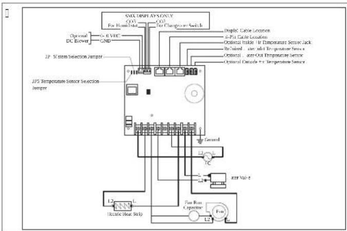
flowchart
graph TD
    A["SMX DISPLAY ONLY"] --> B["For Humidized"]
    A --> C["For Chargeless Switch"]
    B --> D["CND"]
    C --> E["CND"]
    D --> F["Optional DC Button"]
    E --> G["Optional DC Button"]
    F --> H["12P System Selection Jumper"]
    G --> I["12P System Selection Jumper"]
    H --> J["JPS Temperature Sensor Selection Jumper"]
    I --> K["Ground"]
    J --> L["Electric Heat Strip"]
    K --> M["L2"]
    L --> N["L1"]
    M --> O["L2"]
    N --> P["L2"]
    O --> Q["L2"]
    P --> R["L2"]
    Q --> S["L2"]
    R --> T["L2"]
    S --> U["L2"]
    T --> V["L2"]
    U --> W["L2"]
    V --> X["L2"]
    W --> Y["L2"]
    X --> Z["L2"]
    Y --> AA["L2"]
    Z --> AB["L2"]
E Installati'
E/5 E' n option' l' s' nsor install' r' n
natural_image
Diagram of an electronic device showing a connector with an arrow pointing to a port, connected to a cable (no text or symbols present)| Nr/ ' schrij10ing | |
| 1 . itsparing | |
| 2 Lisplaypaneel | |
| 3 Rand | |
| 4 Schroel |
E/5 H't (isplay t'st'n
Q. Nap the Mode icon to select a mode.
Refer tov' vailable Modes and Options for Operations.
√ L isplay icons illuminate to indicate the selected mode.
The display loc s into the last mode selected amer wve seconds of inactivity? then displays the room temperature. The selected mode | SL remains lit.
* mer Qj seconds of inactivity? the display shows the room temperature and enters the IL1S state.
O]] displays on the screen to indicate the O]] state.
NL0000
Y then the display is making a call for heating cooling ^p auT heat ^o or humidity ^f the appropriate Mode indicator blin s for two seconds O' and two seconds O].
I. Nap any icon to wake up the control from the O] or IL | S state.
U. Nap and hold the Mode icon for three seconds to start a SI SSD state.
√ Nhe display goes dar .
'ormal operation continues.
K. Nap and hold the Mode icon for three more seconds to wake up the control.
F/2/1 'schi1bar') o(i'n opti's 0oor r'g' ling
C( cled6Continuous Fan 3 ode
FAULT CODES
)S6- - )inside Sensor Failure
r6FL Clean6Replace Filter
LO6+C Low+C Voltage
S+H High Suppl(+ir Temp
LO651 Sea. later Low Limit
SLP Sleep 3 ode
HPF High Pressure Fault
LPF Low Pressure Fault
PLF Pump Sentr( Fault
)L6--Loop-.ater Sensor
DX PROGRAMMABLE PARAMETERS
P- High Fan Limit
P-2 Low Fan Limit
P-7 Compressor Staging Time Dela
P-/ inside +ir Temperature Sensor Calibration
P-5 Failsale Le-el
P-& Low Voltage 3 onitor
P-9 De-)cing C(cle
P-8 Optional Pump Sentri(
P-9 Displa( Brightness Control
P-0 Fahrenheit or Celsius Selection
P- C(cle Pump with Compressor
P- 2 Re- erse +utomatic Fan Speeds During Heating
P-7 Cool-Onl(3ode
P- / Fan 3 otor Selection
P- 5 Restore Factor( Default Settings
P- & Reser-ed
P-9 Reser-ed
P- 8 +ir Filter Cleaning6Replacement Timer Setting
P-9 Filter Cleaning&Replacement Timer Value 4 Reset
P-20 C+N Bus Unit |D
P-2 C+N Bus Group |D
P-22 Voltage Calibration
P-27 Set Point Temperature Differential
P-2/ Dehumidi5cation 3 ode 3 inimum Temperature
P-25 +uto Fan Speed Temperature Differential
P-2& Suppl(-ir High Temperature Limit
P-29)dle State Dela(
P-28 +uOiliar( Heat 1nable
P-29 Relati-e Humidit( 1nable
P-70 Seawater Low-Limit +djustment
P-7 Humidit(Sensor Calibration
P-72 .ater Inlet Temperature Sensor Calibration
P-77 O+T Sensor Calibration
CW PROGRAMMABLE PARAMETERS
P- High Fan Limit
P-2 Low Fan Limit
P-7 Reser-ed
P-/ inside +ir Temperature Sensor Calibration
P-5 Reser ed
P-& Low Voltage 3 onitor
P-9 Reser-ed
P-8 Reser-ed
P-9 Displa( Brightness Control
P- 0 Fahrenheit or Celsius Selection
P- Reser-ed
P-2 Re-erse+utomatic Fan Speeds During Heating
P-7 Reser-ed
P- / Fan 3 otor Selection
P- 5 Restore Factor, Default Settings
P- & H(dronic. later Val-e Forced Open
P-9. later Temperature Differential
P- 8 +ir Filter Cleaning&Replacement Timer Setting
P- 9 Filter Cleaning6Replacement Timer Value 4 Reset
P-20 C+N Bus Unit D
P-2 C+N Bus Group |D
P-22 Voltage Calibration
P-27 Set Point Temperature Differential
P-2/ Dehumidi5cation 3 ode 3 inimum Temperature
P-25 +uto Fan Speed Temperature Differential
P-2& Suppl( +ir High Temperature Limit
P-29 |dle State Dela(
P-28 +uOiliar( Heat 1nable
P-29 Relati-e Humidit( 1nable
P-70 Reser-ed
P-7 Humidit(Sensor Calibration
P-72. ater Inlet Temperature Sensor Calibration
P-77 O+T Sensor Calibration
BSDSR/NS M" R" NIS BSSck I/B" "R O D DOMETIC.COM/WARRANTY.
MOckN, 'R'MS' k SBBS'O] SS' MR" NIS /ODIS'' L S BSDSR/NS M" R'' NIS Y I I S' 'SR/RIJMS' F' SSML'' cO' N" cN O D MS Na
DOMETIC CORPORATION
MARINE CUSTOMER SUPPORT CENTER
2000 NORTH ANDREWS AVENUE
POMPANO BEACH, FLORIDA, USA 33069
1-800-542-2477
2/2 Si11' rh' (sh' n0isning'r

ADVARSEL. FARE FOR ELEKTRISK STI D2 RAND O! 3ELLER EKSPLOSION/ A angl' n( ' o0' rho( ' ls' a, ,mlg' n( ' a( 0arsl' r 1an r' sult' r' i ( m( s, al( ' ll' r al0orlig p' rsons1a( '/
E A ont' ring
E/5 Installation a, 'n'1stra s'nsor
natural_image
Diagram of an electronic device showing a port with an arrow pointing to it, connected to a cable (no text or symbols present)| Pos/ 's1ri0' ls' | |
| 1 . ds aering | |
| 2 L isplaypanel | |
| 3 Ramme | |
| 4 S rue |
E/5 T' st a, ( isplay' t
Lette a'snit indeholder oplysninger om test a' displayet emer installation.

VI! TI! T. Kun, or D8-'nh' ('r: Ho0' (a,bry('r'n'll'r strm)) 'n til 'nh' ('n) o i11' slu11's og tn n('s)' ('('t sa)) 'ig'n/ Aangl' n ('o0'rhol('ls'a, ('nn'h'n0isning)' ',mr'r b'sla(ig'ls'a, pro(ult't/
Q. Nap the Mode icon to select a mode.
Refer tov* vailable Modes and Options for Operations.
- L isplay icons illuminate to indicate the selected mode.
Nhe display loc s into the last mode selected affer seconds of inactivity? then displays the room temperature. Nhe selected mode |SL| remains lit.
* mer 0j seconds of inactivityp the display shows the room temperature and enters the IL1S state.
O]] displays on the screen to indicate the O]] state.
Y hen the display is ma ing a call for heating ^p cooling ^p auT heat ^p or humidity ^p the appropriate Mode indicator blin s for two seconds O' and two seconds O] ].
- Nap any icon to wave up the control (from the O)] or IL |S state.
U. Nap and hold the Mode icon for three seconds to start a SI SSD state.
√ Mhe display goes dar .
'ormal operation continues.
K. Nap and hold the Mode icon for three more seconds to wake up the control.
| +ir Sensor Fault |
| High Pressure Fault |
| Low Pressure Fault |
| Low +C Fault |
| Pump Sentr' Fault |
FAULT CODES
| S6-- inside Sensor Failure |
| r6FL Clean6Replace Filter |
| LO6+C Low +C Voltage |
| S+H High Suppl(+ir Temp |
| LO6S1 Sea . ater Low Limit |
| SLP Sleep 3 ode |
| HPF High Pressure Fault |
| LPF Low Pressure Fault |
| PLF Pump Sentr(Fault |
| L6-- Loop-. ater Sensor |
DX PROGRAMMABLE PARAMETERS
P- High Fan Limit
P-2 Low Fan Limit
P-7 Compressor Staging Time Dela
P-/ inside +ir Temperature Sensor Calibration
P-5 Failsale Le-el
P-& Low Voltage 3 onitor
P-9 De-)cing C(cle
P-8 Optional Pump Sentr(
P-9 Displa( Brightness Control
P- 0 Fahrenheit or Celsius Selection
P- C(cle Pump with Compressor
P- 2 Re- erse +utomatic Fan Speeds During Heating
P-7 Cool-Onl(3ode
P- / Fan 3 otor Selection
P- 5 Restore Factor( Default Settings
P- & Reser-ed
P-9 Reser-ed
P- 8 +ir Filter Cleaning6Replacement Timer Setting
P-9 Filter Cleaning&Replacement Timer Value 4 Reset
P-20 C+N Bus Unit |D
P-2 C+N Bus Group |D
P-22 Voltage Calibration
P-27 Set Point Temperature Differential
P-2/ Dehumidi5cation 3 ode 3 inimum Temperature
P-25 +uto Fan Speed Temperature Differential
P-2& Suppl(-ir High Temperature Limit
P-29)dle State Dela(
P-28 +uOiliar( Heat 1nable
P-29 Relati-e Humidit( 1nable
P-70 Seawater Low-Limit +djustment
P-7 Humidit(Sensor Calibration
P-72 .ater Inlet Temperature Sensor Calibration
P-77 O+T Sensor Calibration
CW PROGRAMMABLE PARAMETERS
P- High Fan Limit
P-2 Low Fan Limit
P-7 Reser-ed
P-/ inside +ir Temperature Sensor Calibration
P-5 Reser ed
P-& Low Voltage 3 onitor
P-9 Reser-ed
P-8 Reser-ed
P-9 Displa( Brightness Control
P- 0 Fahrenheit or Celsius Selection
P- Reser-ed
P-2 Re-erse + automatic Fan Speeds During Heating
P-7 Reser-ed
P- / Fan 3 otor Selection
P- 5 Restore Factor( Default Settings
P- & H(dronic. later Val-e Forced Open
P-9. later Temperature Differential
P- 8 +ir Filter Cleaning&Replacement Timer Setting
P-9 Filter Cleaning&Replacement Timer Value 4 Reset
P-20 C+N Bus Unit |D
P-2 C+N Bus Group |D
P-22 Voltage Calibration
P-27 Set Point Temperature Differential
P-2/ Dehumidi5cation 3 ode 3 inimum Temperature
P-25 +uto Fan Speed Temperature Differential
P-2& Suppl(+ir High Temperature Limit
P-29 |dle State Dela|
P-28 +uOiliar( Heat 1nable
P-29 Relati-e Humidit( 1nable
P-70 Reser-ed
P-7 Humidit(Sensor Calibration
P-72. ater Inlet Temperature Sensor Calibration
P-77 O+T Sensor Calibration
DA[1]
10 U(b' (ring a, 'D)
DOMETIC AUSTRALIA PTY LTD
1 JOHN DUNCAN COURT
VARSITY LAKES, QLD, 4227
1800-212-121
DOMETIC NEW ZEALAND LTD
373 NEILSON STREET
PENROSE, AUCKLAND, 1061
+64 9 622 1490
Kun Australi'n
00 " vallshantering......GVJ
QI Maranti......GVJ
1 TillhHran('o1u)'nt

b " ' SI/' ] D' Z] P' ational Electrical coded "Bec S-00' c and L c Electrical Systems on Boats
b " ' SI/ " ] D" 0091 P Recreational 'ehicles c ode
/“”“L”
b c S* c l l .0° del l och llP canadian Electrical code
b "Bec S-00 R' Series Recreational 'ehicles
2/2 SI 1' rh' tsan0isningar

VARNIN! . RISK FqR ELEKTRISK STq T2 RAND OCH3ELLER E8PLOSION/O) an un('rlot'ratt,HIDa,HIDan('0arningar1an,HID('n bli (H(s,all 'll'r all0arlig p'rsons1a(a/
5 A0s' ( ( an01 n( ning
Ext'mt 7-r'll UJ maTimalt
Pu) put' ,' 1t
JFlVhpflFG9 Ytr COV\~
JV hp f] PUZ Y hr I UJ \~
Ko) pr'ssorut','It
G hp fJ ZV Y tr GOV \~
I hp fQ°K9 Y hr I UJ \~
C- -1opplingssch') a
I
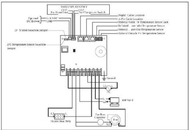
flowchart
graph TD
    A["SmartDisplaySonic"] --> B["Q13"]
    A --> C["Q23"]
    B --> D["For Hum/Watt"]
    C --> E["For Charge/Power Switch"]
    D --> F["Spread DC Bower"]
    D --> G["GND"]
    E --> H["Display Cable Location"]
    E --> I["8-Pat Cable Location"]
    E --> J["Optional Inside Air Temperature Sensor Jack"]
    E --> K["Restricted Air and Temperature Sensor"]
    E --> L["Optional -air-Out Temperature Sensor"]
    E --> M["Optional Outside Air Temperature Sensor"]
    N["JPS Temperature Sensor Selection Jumper"] --> O["Ground"]
    N --> P["L1"]
    N --> Q["L2"]
    N --> R["L3"]
    N --> S["L4"]
    N --> T["L5"]
    N --> U["L6"]
    N --> V["L7"]
    N --> W["L8"]
    N --> X["L9"]
    N --> Y["L10"]
    N --> Z["L11"]
    N --> AA["L12"]
    N --> AB["L13"]
    N --> AC["L14"]
    N --> AD["L15"]
    N --> AE["L16"]
    N --> AF["L17"]
    N --> AG["L18"]
    N --> AH["L19"]
    N --> AI["L20"]
    N --> AJ["L21"]
    N --> AK["L22"]
    N --> AL["L23"]
    N --> AM["L24"]
    N --> AN["L25"]
    N --> AO["L26"]
    N --> AP["L27"]
    N --> AQ["L28"]
    N --> AR["L29"]
    N --> AS["L30"]
E Installation
natural_image
Diagram of an electronic device showing a connector with an arrow pointing to a port, connected to a cable (no text or symbols present)| Pos/ 's1ri0ning | |
| 1 . ttag |
| Pos/ 's1ri0ning | |
| 2 L isplaypanel | |
| 3 In'atmning | |
| 4 S ruv |
E/5 T' sta (isplay'n
- Nap the Mode icon to select a mode.
Refer tov* vailable Modes and Options for Operation#.
- L isplay icons illuminate to indicate the selected mode.
Nhe display loc s into the last mode selected amer Wve seconds of inactivity ^9 then displays the room temperature. Nhe selected mode | SL remains lit.
* mer 0J seconds of inactivityF the display shows the room temperature and enters the IL1S state.
O]] displays on the screen to indicate the O]] state.
Y hen the display is ma ing a call for heating cooling for heat or humidity the appropriate Mode indicator blin s for two seconds O' and two seconds O].
[ . Nap any icon to wave up the control from the O] or IL |S state.
U. Nap and hold the Mode icon for three seconds to start a SI SSD state.
√ Mhe display goes dar .
ormal operation continues.
K. Nap and hold the Mode icon for three more seconds to wake up the control.
C( cled6Continuous Fan 3 ode
FAULT CODES
)S6- - )inside Sensor Failure
r6FL Clean6Replace Filter
LO6+C Low+C Voltage
S+H High Suppl(+ir Temp
LO651 Sea. later Low Limit
SLP Sleep 3 ode
HPF High Pressure Fault
LPF Low Pressure Fault
PLF Pump Sentr( Fault
)L6--Loop-.ater Sensor
DX PROGRAMMABLE PARAMETERS
P- High Fan Limit
P-2 Low Fan Limit
P-7 Compressor Staging Time Dela
P-/ inside +ir Temperature Sensor Calibration
P-5 Failsale Le-el
P-& Low Voltage 3 onitor
P-9 De-)cing C(cle
P-8 Optional Pump Sentri(
P-9 Displa( Brightness Control
P- 0 Fahrenheit or Celsius Selection
P- C(cle Pump with Compressor
P- 2 Re- erse +utomatic Fan Speeds During Heating
P-7 Cool-Onl(3ode
P- / Fan 3 otor Selection
P- 5 Restore Factor( Default Settings
P- & Reser-ed
P-9 Reser-ed
P- 8 +ir Filter Cleaning6Replacement Timer Setting
P-9 Filter Cleaning6Replacement Timer Value 4 Reset
P-20 C+N Bus Unit |D
P-2 C+N Bus Group |D
P-22 Voltage Calibration
P-27 Set Point Temperature Differential
P-2/ Dehumidi5cation 3 ode 3 inimum Temperature
P-25 +uto Fan Speed Temperature Differential
P-2& Suppl(-ir High Temperature Limit
P-29)dle State Dela(
P-28 +uOiliar( Heat 1nable
P-29 Relati-e Humidit( 1nable
P-70 Seawater Low-Limit +djustment
P-7 Humidit(Sensor Calibration
P-72 .ater Inlet Temperature Sensor Calibration
P-77 O+T Sensor Calibration
CW PROGRAMMABLE PARAMETERS
P- High Fan Limit
P-2 Low Fan Limit
P-7 Reser-ed
P-/ inside +ir Temperature Sensor Calibration
P-5 Reser ed
P-& Low Voltage 3 onitor
P-9 Reser-ed
P-8 Reser-ed
P-9 Displa( Brightness Control
P- 0 Fahrenheit or Celsius Selection
P- Reser-ed
P-2 Re-erse + automatic Fan Speeds During Heating
P-7 Reser-ed
P- / Fan 3 otor Selection
P- 5 Restore Factor, Default Settings
P- & H(dronic. later Val-e Forced Open
P-9. later Temperature Differential
P- 8 +ir Filter Cleaning&Replacement Timer Setting
P-9 Filter Cleaning&Replacement Timer Value 4 Reset
P-20 C+N Bus Unit D
P-2 C+N Bus Group |D
P-22 Voltage Calibration
P-27 Set Point Temperature Differential
P-2/ Dehumidi5cation 3 ode 3 inimum Temperature
P-25 +uto Fan Speed Temperature Differential
P-2& Suppl+ir High Temperature Limit
P-29 |dle State Dela(
P-28 +uOiliar( Heat 1nable
P-29 Relati-e Humidit( 1nable
P-70 Reser-ed
P-7 Humidit(Sensor Calibration
P-72. ater Inlet Temperature Sensor Calibration
P-77 O+T Sensor Calibration
10 F' lsH1ning
DOMETIC AUSTRALIA PTY LTD
1 JOHN DUNCAN COURT
VARSITY LAKES, QLD, 4227
1800-212-121
DOMETIC NEW ZEALAND LTD
373 NEILSON STREET
PENROSE, AUCKLAND, 1061
+64 9 622 1490
! ll'r'n( ast ,Hr Australi'n
1 Symbol for laring....OVI
U]ors rimsmessig bru ....0VI
Oj]eilretting....CXK
00 "vällshändtering....CXX
QI Maranti.....GXX
1 R' lat' rt' ( o1u) ' nt' r

b " " ' SI/ " ] D" Z] P' ational Electrical coded "Bec S-00" c and L c Electrical Systems on Boats
b " ' SI/' ] D" 0091 P Recreational ' ehicles c ode
canada
b c S* c l l .0° Darts I and llP canadian Electrical code
b "Bec S-00 R' Series ^P Recreational 'ehicles
2/2 Si11' rh' tsr' gl' r

ADVARSEL. FARE FOR ELEKTRISK STI T2 RANN O! 3ELLER EKSPLOSRON/ Unnlat' ls' a0 o,mlg' ( ' ,mlg' n( ' a( 0arsl' n' 1an ,mr' til ( m( ' ll' r al0orlig p'rsons1a( '/
E1st'mt 7-r'IP uJ ma s
Pu) p' ' ' 1t J FI V hp fJ FQ9 Y ir SOV '\~
JV hp fJ PUZ Y hr I UJ \~
Ko) pr'ssor','1t G hp || PZV Y tr GOV \~
I hp fQ?K9 Y hr I UJ \~
La0'st' (ri,tst') p'ratur] p] fCZFZ[ pch
A a1si) al o) gi0' ls'st') p'ratur,or (ri,t G[ ] o] f[ ] 11 pc
Aalsi) al' RH-,orhol(991 Pi e- ondenserende
Stm),orbrul u V Y
B Koblingss10') a'r
E/5 A ont' ring a0 s' nsor so) till' ggsutstyr
natural_image
Diagram of an electronic device showing a connector with an arrow pointing to a component, connected to a cable (no text or symbols present)| Pos/ 's1ri0' ls' | |
| 1 Apning | |
| 2 Lisplaypanel | |
| 3 Ramme | |
| 4 S rue |
E/5 T' st ( isplay' t
A anu'll 0i,t') o( us
- Nap the Mode icon to select a mode.
Refer tov* vailable Modes and Options for Operation#.
- L isplay icons illuminate to indicate the selected mode.
Nhe display loc s into the last mode selected amer Wve seconds of inactivity ^9 then displays the room temperature. Nhe selected mode | SL remains lit.
* mer 0J seconds of inactivityF the display shows the room temperature and enters the IL1S state.
O]] displays on the screen to indicate the O]] state.
Y hen the display is ma ing a call for heating cooling for heat or humidity the appropriate Mode indicator blin s for two seconds O' and two seconds O].
[ . Nap any icon to wave up the control from the O] or IL |S state.
U. Nap and hold the Mode icon for three seconds to start a SI SSD state.
√ Mhe display goes dar .
ormal operation continues.
K. Nap and hold the Mode icon for three more seconds to wave up the control.
F/2/1 Tilg0' ng' lig') o('ll'r og alt'mati0'r,or b't' ning
C( cled6Continuous Fan 3 ode
FAULT HELP
+ir Sensor Fault
High Pressure Fault
Low Pressure Fault
Low + C Fault
Pump Sentr' Fault
FAULT CODES
)S6- - )inside Sensor Failure
r6FL Clean6Replace Filter
LO6+C Low+C Voltage
S+H High Suppl(+ir Temp
LO651 Sea. later Low Limit
SLP Sleep 3 ode
HPF High Pressure Fault
LPF Low Pressure Fault
PLF Pump Sentr( Fault
)L6--Loop-.ater Sensor
DX PROGRAMMABLE PARAMETERS
P- High Fan Limit
P-2 Low Fan Limit
P-7 Compressor Staging Time Dela
P-/ inside +ir Temperature Sensor Calibration
P-5 Failsale Le-el
P-& Low Voltage 3 onitor
P-9 De-)cing C(cle
P-8 Optional Pump Sentri(
P-9 Displa( Brightness Control
P- 0 Fahrenheit or Celsius Selection
P- C(cle Pump with Compressor
P- 2 Re- erse +utomatic Fan Speeds During Heating
P-7 Cool-Onl(3ode
P- / Fan 3 otor Selection
P- 5 Restore Factor( Default Settings
P- & Reser-ed
P-9 Reser-ed
P- 8 +ir Filter Cleaning6Replacement Timer Setting
P-9 Filter Cleaning6Replacement Timer Value 4 Reset
P-20 C+N Bus Unit |D
P-2 C+N Bus Group |D
P-22 Voltage Calibration
P-27 Set Point Temperature Differential
P-2/ Dehumidi5cation 3 ode 3 inimum Temperature
P-25 +uto Fan Speed Temperature Differential
P-2& Suppl(-ir High Temperature Limit
P-29)dle State Dela(
P-28 +uOiliar( Heat 1nable
P-29 Relati-e Humidit( 1nable
P-70 Seawater Low-Limit +djustment
P-7 Humidit(Sensor Calibration
P-72 .ater Inlet Temperature Sensor Calibration
P-77 O+T Sensor Calibration
CW PROGRAMMABLE PARAMETERS
P- High Fan Limit
P-2 Low Fan Limit
P-7 Reser-ed
P-/ inside +ir Temperature Sensor Calibration
P-5 Reser ed
P-& Low Voltage 3 onitor
P-9 Reser-ed
P-8 Reser-ed
P-9 Displa( Brightness Control
P- 0 Fahrenheit or Celsius Selection
P- Reser-ed
P-2 Re-erse -utomatic Fan Speeds DuringHeating
P-7 Reser-ed
P- / Fan 3 otor Selection
P- 5 Restore Factor, Default Settings
P- & H(dronic. later Val-e Forced Open
P-9. later Temperature Differential
P- 8 +ir Filter Cleaning&Replacement Timer Setting
P- 9 Filter Cleaning6Replacement Timer Value 4 Reset
P-20 C+N Bus Unit D
P-2 C+N Bus Group |D
P-22 Voltage Calibration
P-27 Set Point Temperature Differential
P-2/ Dehumidi5cation 3 ode 3 inimum Temperature
P-25 +uto Fan Speed Temperature Differential
P-2& Suppl+ir High Temperature Limit
P-29 |dle State Dela(
P-28 +uOiliar( Heat 1nable
P-29 Relati-e Humidit( 1nable
P-70 Reser-ed
P-7 Humidit(Sensor Calibration
P-72. ater Inlet Temperature Sensor Calibration
P-77 O+T Sensor Calibration
10 F' ilr' tting
DOMETIC AUSTRALIA PTY LTD
1 JOHN DUNCAN COURT
VARSITY LAKES, QLD, 4227
1800-212-121
DOMETIC NEW ZEALAND LTD
373 NEILSON STREET
PENROSE, AUCKLAND, 1061
+64 9 622 1490
! D'1('r 1un,or Australia
b " ' SI/ " ] D" Z] P' ational Electrical coded "Bec S-00' c and L c Electrical Systems on Boats
b " ' SI/ " ] D" 0091 P Recreational ' ehicles c ode
/anada
b c S* c l l .0° Darts I and llP canadian Electrical code
b "Bec S-QQ R' Series ^P Recreational 'ehicles
2/2 TurOallisuusohD''t

VAROITUS. St HKq ISKUN2 TULIPALON rA3TAI Rt rt HDYKSEN VAARA/ S' uraa0i' n 0aroitust' n lai) inlyHnti 0oi Dohtaa 1uol') aan tai 0a1a0aan 0a) ) aan/
C- -Doh( otus1aa0io
□
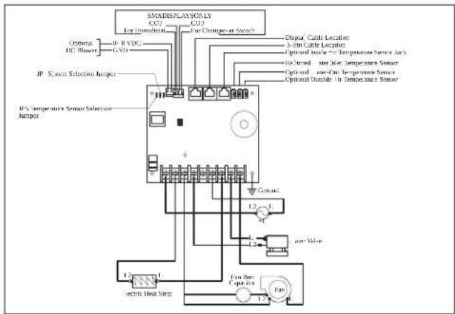
E As' nnus
E/5 Valinnais' n anturin as' nta) in' n
natural_image
Diagram of an electronic device showing a connector with an arrow pointing to a port, connected to a cable (no text or symbols present)Refer tov* vailable Modes and Options for Operations,
- L isplay icons illuminate to indicate the selected mode.
Nhe display loc s into the last mode selected arer wve seconds of inactivity? then displays the room temperature. Nhe selected mode |SL remains lit.
* mer Q; seconds of inactivity; the display shows the room temperature and enters the IL15 state.
O] displays on the screen to indicate the O] state.
Y hen the display is ma ing a call for heating ^p cooling ^p auT heat ^p or humidity ^p the appropriate Mode indicator blin s for two seconds O' and two seconds O] ].
. Nap any icon to wave up the control from the O] or IL |S state.
U. Nap and hold the Mode icon for three seconds to start a SI SSD state.
√ The display goes dar .
'ormal operation continues.
K. Nap and hold the Mode icon for three more seconds to wave up the control.
F/2/1 KI yt' ttl 0issl ol' 0at 11 yttHtilat Da -Oaihto' h( ot
Ku0a1' Tila la toi) into


C( cled6Continuous Fan 3 ode
FAULT HELP
+ir Sensor Fault
High Pressure Fault
Low Pressure Fault
Low + C Fault
Pump Sentr' Fault
FAULT CODES
)S6- - )inside Sensor Failure
r6FL Clean6Replace Filter
LO6+C Low+C Voltage
S+H High Suppl(+ir Temp
LO651 Sea. later Low Limit
SLP Sleep 3 ode
HPF High Pressure Fault
LPF Low Pressure Fault
PLF Pump Sentr( Fault
)L6--Loop-.ater Sensor
DX PROGRAMMABLE PARAMETERS
P- High Fan Limit
P-2 Low Fan Limit
P-7 Compressor Staging Time Dela
P-/ )inside +ir Temperature Sensor Calibration
P-5 Failsale Le-el
P-& Low Voltage 3 onitor
P-9 De-)cing C(cle
P-8 Optional Pump Sentri
P-9 Displa( Brightness Control
P- 0 Fahrenheit or Celsius Selection
P- C(cle Pump with Compressor
P- 2 Re- erse +utomatic Fan Speeds During Heating
P-7 Cool-Onl(3ode
P- / Fan 3 otor Selection
P- 5 Restore Factor( Default Settings
P- & Reser-ed
P-9 Reser-ed
P- 8 +ir Filter Cleaning6Replacement Timer Setting
P-9 Filter Cleaning&Replacement Timer Value 4 Reset
P-20 C+N Bus Unit |D
P-2 C+N Bus Group |D
P-22 Voltage Calibration
P-27 Set Point Temperature Differential
P-2/ Dehumidi5cation 3 ode 3 inimum Temperature
P-25 +uto Fan Speed Temperature Differential
P-2& Suppl(-ir High Temperature Limit
P-29)dle State Dela(
P-28 +uOiliar( Heat 1nable
P-29 Relati-e Humidit( 1nable
P-70 Seawater Low-Limit +djustment
P-7 Humidit(Sensor Calibration
P-72 .ater)nlet Temperature Sensor Calibration
P-77 O+T Sensor Calibration
CW PROGRAMMABLE PARAMETERS
P- High Fan Limit
P-2 Low Fan Limit
P-7 Reser-ed
P-/ inside +ir Temperature Sensor Calibration
P-5 Reser ed
P-& Low Voltage 3 onitor
P-9 Reser-ed
P-8 Reser-ed
P-9 Displa( Brightness Control
P- 0 Fahrenheit or Celsius Selection
P- Reser-ed
P- 2 Re- erse -utomaticFan Speeds During Heating
P-7 Reser-ed
P- / Fan 3 otor Selection
P- 5 Restore Factor( Default Settings
P- & H(dronic. later Val-e Forced Open
P-9. later Temperature Differential
P- 8 +ir Filter Cleaning&Replacement Timer Setting
P- 9 Filter Cleaning6Replacement Timer Value 4 Reset
P-20 C+N Bus Unit D
P-2 C+N Bus Group |D
P-22 Voltage Calibration
P-27 Set Point Temperature Differential
P-2/ Dehumidi5cation 3 ode 3 inimum Temperature
P-25 +uto Fan Speed Temperature Differential
P-2& Suppl+ir High Temperature Limit
P-29 |dle State Dela(
P-28 +uOiliar( Heat 1nable
P-29 Relati-e Humidit( 1nable
P-70 Reser-ed
P-7 Humidit(Sensor Calibration
P-72. ater Inlet Temperature Sensor Calibration
P-77 O+T Sensor Calibration
10 Vian' tsintl
b 'Bec S-00 R' SeriesF Recreational 'ehicles
Pols1i
K Og-lne ws az-w i....0[U
V Specy ^1/2 acje....Q[ K
b " ' SI/' ] D" Z] P' ational Electrical coded "Bec S-00' c and L c Electrical Systems on Boats
b " ' SI/ " ] D" 0091 P Recreational ' ehicles c ode
/anada
b c S' c l l .0° czę*ci l i ll° canadian Electrical code
2/2 - s1a4ów1i b' 4pi' c4' ystwa

6/2 Fun1c0' wyvwi'tlac4a
| X "Ir COV" A oc wylvciowa w' ntylatora | |
| X "Ir I UJ"~ | |
| A oc wylvciowa 4aworu V' r COV/I UJ" | ~ |
| Tyllo ( la instalaci C- : - ylvci' ( o( atlo-w'0 nagr4' wnicy 'l'1tryc4n'0:4 wylo-r4ystani') wylvcia spreżarli L.1 i L.2) | Uj" ma symalnie |
Tria1 4' wnetr4ny | X "
natural_image
Diagram of an electronic device showing a connector with an arrow pointing to a port, connected to a cable (no text or symbols present)E/5 T' stowani' wyvwi' tlac4a
Q. Nap the Mode icon to select a mode.
Refer tov' vailable Modes and Options for Operations.
- L isplay icons illuminate to indicate the selected mode.
The display loc s into the last mode selected a##r five seconds of inactivity ^2 then displays the room temperature. The selected mode | SL remains lit.
* mer QJ seconds of inactivityf the display shows the room temperature and enters the IL1S state.
O]] displays on the screen to indicate the O]] state.
Y hen the display is ma ing a call for heating ^b cooling ^b auT heat ^b or humidity ^b the appropriate Mode indicator blin s for two seconds O' and two seconds O] ].
. Nap any icon to wave up the control from the O] or IL |S state.
U. Nap and hold the Mode icon for three seconds to start a SI SSD state.
PL000
√ The display goes dar .
ormal operation continues.
K. Nap and hold the Mode icon for three more seconds to wave up the control,
F/6/6 I('nty,i1acda 1o(ów bxę(ów progra) owania
□
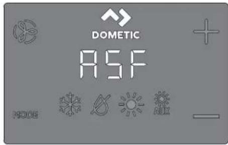
C( cled6Continuous Fan 3 ode
FAULT CODES
)S6- - )inside Sensor Failure
r6FL Clean6Replace Filter
LO6+C Low+C Voltage
S+H High Suppl(+ir Temp
LO651 Sea. later Low Limit
SLP Sleep 3 ode
HPF High Pressure Fault
LPF Low Pressure Fault
PLF Pump Sentr(Fault
)L6--Loop-.ater Sensor
DX PROGRAMMABLE PARAMETERS
P- High Fan Limit
P-2 Low Fan Limit
P-7 Compressor Staging Time Dela
P-/ inside +ir Temperature Sensor Calibration
P-5 Failsale Le-el
P-& Low Voltage 3 onitor
P-9 De-)cing C(cle
P-8 Optional Pump Sentri(
P-9 Displa( Brightness Control
P-0 Fahrenheit or Celsius Selection
P- C(cle Pump with Compressor
P- 2 Re- erse +utomatic Fan Speeds During Heating
P-7 Cool-Onl(3ode
P- / Fan 3 otor Selection
P- 5 Restore Factor( Default Settings
P- & Reser-ed
P-9 Reser-ed
P- 8 +ir Filter Cleaning6Replacement Timer Setting
P-9 Filter Cleaning6Replacement Timer Value 4 Reset
P-20 C+N Bus Unit |D
P-2 C+N Bus Group |D
P-22 Voltage Calibration
P-27 Set Point Temperature Differential
P-2/ Dehumidi5cation 3 ode 3 inimum Temperature
P-25 +uto Fan Speed Temperature Differential
P-2& Suppl(-ir High Temperature Limit
P-29)dle State Dela(
P-28 +uOiliar( Heat 1nable
P-29 Relati-e Humidit( 1nable
P-70 Seawater Low-Limit +djustment
P-7 Humidit(Sensor Calibration
P-72 .ater Inlet Temperature Sensor Calibration
P-77 O+T Sensor Calibration
CW PROGRAMMABLE PARAMETERS
P- High Fan Limit
P-2 Low Fan Limit
P-7 Reser-ed
P-/ inside +ir Temperature Sensor Calibration
P-5 Reser ed
P-& Low Voltage 3 onitor
P-9 Reser-ed
P-8 Reser-ed
P-9 Displa( Brightness Control
P- 0 Fahrenheit or Celsius Selection
P- Reser-ed
P-2 Re-erse + automatic Fan Speeds During Heating
P-7 Reser-ed
P- / Fan 3 otor Selection
P- 5 Restore Factor, Default Settings
P- & H(dronic. later Val-e Forced Open
P-9. later Temperature Differential
P- 8 +ir Filter Cleaning&Replacement Timer Setting
P-9 Filter Cleaning6Replacement Timer Value4 Reset
P-20 C+N Bus Unit D
P-2 C+N Bus Group |D
P-22 Voltage Calibration
P-27 Set Point Temperature Differential
P-2/ Dehumidi5cation 3 ode 3 inimum Temperature
P-25 +uto Fan Speed Temperature Differential
P-2& Suppl+ir High Temperature Limit
P-29 |dle State Dela(
P-28 +uOiliar( Heat 1nable
P-29 Relati-e Humidit( 1nable
P-70 Reser-ed
P-7 Humidit(Sensor Calibration
P-72. ater jinlet Temperature Sensor Calibration
P-77 O+T Sensor Calibration
10 Usuwani' ust'r' 1
DOMETIC AUSTRALIA PTY LTD
1 JOHN DUNCAN COURT
VARSITY LAKES, QLD, 4227
1800-212-121
DOMETIC NEW ZEALAND LTD
373 NEILSON STREET
PENROSE, AUCKLAND, 1061
+64 9 622 1490
Stany CD' (noc4on' illKana(a
NRSSĆ OMR" ' Ic ZO' SJ MY " R" ' c JI JSSN L OSNĘD' " " 'SNRO' IS DOMETIC.COM/WARRANTY.
Y R" ZIS DeN" ÚI. B Y cSI. BSZDE" N' SMO. ZeS/" ' I" SMZSMDI " RZ"
OMR ^* ' Ic ZO' SMO MY "R" ' cJI " IS•e S/O' N" /NOY " C SIE, Za
DOMETIC CORPORATION
MARINE CUSTOMER SUPPORT CENTER
2000 NORTH ANDREWS AVENUE
POMPANO BEACH, FLORIDA, USA 33069
1-800-542-2477
- s4yst1i' inn'r giony
X Sch+my zapojenia....| J |
Z Mont()....|J|
[ Obsluha....I ] U
9 Strom navig( cie syst+mom....1 00
Oj Odstra"ovanie por, ch....| OI
00 | i vid( cia....| QK
QI Z(ru a....| QK
1 Sú0isiac' (o1u) 'nty

' (vod nalmont() alobsluhu n(jdete online naladrese qr.dometic.com/bes] p'.
2 Vys0' tl' ni' sy) bolo0
Sign( lne slovo identi" uje bezpečnostn- spr( vy alspr( vy o' od( ch na majet u altie) označuje stupe" alebo , rove" z( va) nosti nebezpečenstva.

VÝSTRAHA.
b " ' SI/ " ] D" 0091 P Recreational 'ehicles c ode
/anada
b c S" c l l .0° časti l a llP canadian Electrical code
b "Bec S-00 s+ria R' P Recreational 'ehicles
2/2 '4p' čnostnP polyny

VÝSTRAHA. NE ECPEČENSTVO CbSAHU ELEKTRICKÝA PRÚDOA 2 POŽIARU A3ALE O VÝ UCHU/ N' (o( ržani' nasl' (uůcích 0aro0aní ) Už') at' 4al nasl' (o1 s) rt' al' bo 0ažn' poran' ni'/
Dou) ívajte iba n( hradn+ diely a omponenty od spoločnosti L ometicitor+ s, Gpeci lne schv( len+ na pou) itie so zariadením.
yhnite sa nespr( vnej inótal( ciíf nastavovaniu ^2 , prav( mř servisu či, dr) be zariadenia. Servis a, dr) bu musí vy on( vaš iba valižč ovan... servisn... pracovní .
Nento v...robo ) iadnym spôsobom n') ' ñt'. Úprava mô) e by mimoriadne nebezpečn( .
Nento v...robo sa m( inčtalova» v ontrolovanom vn, tornom prostredí.
E A ontaž
natural_image
Diagram of an electronic device showing a port with an arrow pointing to it, connected to a cable (no text or symbols present)U. Domocou Gtyroch dodan...ch s rutie pripevnite panel displeja priehrad e.
N' použi0aht' usahovač u s rutie ani s ut y neu«ahujte príliš vel' ...m usahovacím momentom.
K. R(mče nasad'te na r(m panela displeja.
[]
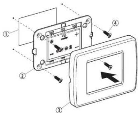
| Po4/ Opis | |
| 1 .rez | |
| 2 Danel displeja | |
| 3 R/mče | |
| 4 S rut a |
E/5 T' stoOani' (ispl'Da
- Nap the Mode icon to select a mode.
Refer tov* vailable Modes and Options for Operations,
- L isplay icons illuminate to indicate the selected mode.
Nhe display loc s into the last mode selected arrer Wve seconds of inactivity? then displays the room temperature. Nhe selected mode I SL remains lit.
* mer Q] seconds oQ inactivity ^F the display shows the room temperature and enters the IL I S state.
O]] displays on the screen to indicate the O]] state.
Y hen the display is ma ing a call for heating cooling auT heat or humidity the appropriate Mode indicator blin s for two seconds O' and two seconds O].
- Map any icon to wave up the control from the O] or IL |S state.
U. Nap and hold the Mode icon for three seconds to start a SI SSD state.
√ Nhe display goes dar .
'ormal operation continues.
K. Nap and hold the Mode icon for three more seconds to wave up the control.
F/2/1 DostupnP r'ži) y a ) ožnosti pr'0a(41y
| Ilona R'ži) a ,unlcia | |
| I ona re} imu chladenia sa rozsvieti?ed'je vybrat...re} im chladenia alebo ed'sa jednot a nach'dza v automatic om re} ime cy lu chladenia. ] unguje iba chladiaci syst+m. ' teplota o olia lesne pod po) adovan, hodnotužariadenie neprejde automatic y do re} imu vy urovania. | |
| I ona re} imu odvlhčovania sa rozsvieti?ed'je vybrat...re} im odvlhčovania. Kento re} im reguluje vlh os> v obdobiach?ed'v pla-vidle nie je pos(d a2 a zabra'uje po lesu teploty v abíne pod minim{lnu predvolen, teplotu. Počas r' gulaci'Olhlosti:b'entil tor zais-uje cir ul( ciu vzduchu UJ min.b Neplota vzduchu sa meria a zaznamení va.b Do uplynutí UJ min sa spustí cy lus chladenia?tor,trv(F ...m sa teplota nezní)i o l p] f0 pc' alebo ...m cy lus chladenia netrv( maTim( Ine jednu hodinu.b „tyri hodiny po dosiahnutí teploty alebo po uplynutí časov+ho limitu cy lu chladenia sa cy lus opa uje.Pri r' gulacii t' ploty:b'je po UJ min cir ul( cie vzduchu ventil( torom nameran( teplota na , rovní štandardn+ho tov( rens +ho nastavenia VJ o] f0) och alebo nad touto hodnotou?spustí sa cy lus chladenia na regul( ciu vlh osú.b'je teplota niíčia ne) Vj p] f0 pc'h začne sa cy lus vy uro-vania. cy lus vy urovania po račuje? ...m teplota nedosiah-ne hodnotu VJ p] f0 pc' alebo ...m cy lus vy urovania netrv( maTim( Ine jednu hodinu.b „tyri hodiny po dosiahnutí teploty alebo po uplynutí časov+ho limitu cy lu chladenia/vy urovania sa cy lus zopa uje a v) dy sa urči' či je potrebn+ chladenie alebo vy urovanie. | |
| POCNbA KA I en pre syst-my L ga cy lus vy urova-nia v re} ime odvlhčovania neprebelne?ed'je o o-lit( teplota ni) Gia ne) KJ p] fKPK pc t. No chr( ni on-denz( tor pred zamznutím. Syst+my v onligur( cii s ele tric ...m ohrevom spustia cy lus vy urovania v re-) ime odvlhčovania bez ohľadu na teplotu v abíne. | |
| I ona re} imu vy urovania sa rozsvieti?ed'je vybrat...re} im vy u-rovania alebo ed'sa jednot a nach(dza v automatic om re) ime cy lu vy urovania. [unguje iba syst+m vy urovania. " teplota o olia st, pne nad po) adovan, hodnotužariadenie neprejde automatic y do re} imu chladenia. | |
| I ona re} imu prídavn-ho vy urovania sa rozsvieti?ed'je v pre-v(dz e voliteľn prídavn...ele tric ...ohrievač." teplota o olia st, pne nad po) adovan, hodnotužariadenie neprejde automa-tic y do re} imu chladenia. | |
| I ona re} imu vypnutia. 'Get y riadiace v .stupy s, vypnut+. ' a displeji sa zobraži teT O)] 'eD'. Něh. 'Get y nastavenia sa ulo- } ia v památi nezi( vislej od napl jania. | |
| I ona re} imu zapnutia. 'Get y riadiace v .stupy s, zapnut+ a na displeji sa zobrazuje a tu( Iny stav prev(dz y. ' a displeji sa zobra-zi teplota v abíne. ' Get y parametre 'unguj, podľa nastavenia. | |
| I ony automatic -ho re) imu sa rozsvietia?ed'je syst+m v auto-matic om re} ime? tor...sa podľa potreby prepne na chladenie alebo vy urovanie! aby sa dosiahla nastavení( hodnota teploty./ed'je vybrat. automatic ... re) impl syst Im podľa potreby zabez-pečuje vy urovanie aj chladenie. Indi {tory chladenia a vy urova-nia alebo i ony chladenia a prídavn+ho vy urovania svietia v s, la-de s prev(dz ou automatic -ho re) imu. |
| Ilona R' Ži) a ,unlcia | |
| I onaFan umo" uje pou) ivatel'ovi prepína> medzi včet ...mi rôz- nymi ot( č ami ventil( tora. / dispozícii je automatic ... re) im a hodnoty OšIV čiz niz a? I z stredne niz a? Uz stredn( P Kz stredne vyso { a Vz vyso { r chlosó. Ot' č y ventil( tora sa reguluj, auto- matic y na z! lade predvolen...ch a naprogramovan ch hodnot. ' astavenia menu programu D-č a D-1 upravuj, hodnoty maTim( I- nych a minim( Inych ot( č oventil( tora. b Ot( č y ventil( tora sa zní) uj, F ed' sa v re) ime chladenia blí) i dosiahnutie nastavenej hodnoty teploty? a ed' sa dosiahne na- staven( hodnotal' ventil( tor pracuje na niz ych ot( č ach. b " utomatic . regul( ciu ot( č oventil( tora mo) no v re) ime vy- urovania zmeniF ed' sa parameter D-ql nastavi na hodnotu „rS] v. Blí) šie in'orm( cie zis ate v časti „Programovanie regul( - torav. b " utomatic ... re) im ventil( tora určuje po) adovan+ ot( č y ven- til( tora na z( lade teplotn+ho rozdielu. No zaisuje dosiahnu- tie naj. činnejčej regul( cie teploty a pomalcie ot( č y s tichčim chodom ventil( tora. * chcete vybra+ automatic ... re) im venti- l( toraž u nite na i onuFan a dr) te na nej prst? ...m sa na disp- leji nezobrazí symbol ,,v. iPOCNbA KA Dozrite si časé, ' . ber parametrav. Do stanovení hodnoty najvyGšieho a najni) Gieho počtu ot( č oventil( tora určí prístroj automatic y zost' vaj, - ce hodnoty ot( č o F pre automatic ... aj manu( Iny re- ) im ventil( tora. | |
| Manu( Iny re) im ventil( tora umo) " uje v. ber onzistenm. ch po) a- dovan...ch ot( č oventil( tora. / dispozícii je pá» manu( lne nasta- viteIn. ch , rovní ot( č oventil( tora: vyso ( P stredne vyso ( P stred- n( P stredne níz a a níz a. Do vy onaní v. beru sa na displeji rozs- vieti číslo , rovne ot( č o. b Ĥu nite na i onuFan a dr) te na nej prst? . m neprejdete z au- tomatic ej na manu( Inu prev( dz u ventil( tora. b Ĥu nite na i onuFan a dr) te na nej prst? čim prev( dzate ma- nu( Inym nastavením ot( č oventil( tora od níz ej po vyso , rove". b Ĥu nite na i onuFan a dr) te na nej prst? . m sa nevr( tite z ma- nu( lnej spá» na automatic , prev( dz u ventil( tora. | |
| ' astavenie | en ventil( tor sl.) i na cir ul( ciu vzduchu? ed' nie je potrebn+ chladenie ani vy urovanie. C. ' rejime vypnuria »u nutím na i onuFan a uvoľnením prstu vyberte po) adovan, , rove" ot( č oventil( tora. iPOCNbA KA Zapnutím regul( tora sa ventil( tor vr' ti do automatic +ho re) imu alebo na posledn+ vybrat+ manu( lne nastavenie ventil( tora. | |
| c y lic ../nepretr) it.. re) im ventil( tora ' entil( tor mo) no nastavi« ta P aby pracoval nepretr) ite v) dy? ed' je syst m zapnut. P alebo ho mo) no nastavi« ta P aby sa zapinal a v z( vislosti od cy lov chladenia alebo vy urovania. C. Ťu nite na i onuFan a podr) te na nej prst pás se , nd. ' a displeji sa zobrazí teTt c cC P ed' je prev( dz a nastaven( na cy lic .. re) im. ' a displeji sa zobrazí teTt c O' F ed' je prev( dz a nastaven( na nepretr) it.. re) im. |
F/5 Použí0ani' o0la( aci' ho pan' la ( ispl' Da
'asleduj, ca tabul' a podrobne uv(dza ombin(cie i on ^2 tor+ sa maj, pou)i na a tiv(ciu rôznych'un cií regul(tora.
Ko) binacia ilon Na40y ilon a ich ,un1cia
MODE 4

Mode a Up
' stup do ponu y programovaniaa
- Ťu nite s, časne a podr) te stlačen- tri se undy² ed' je regul( tor v re) ime vypnutia.
C( cled6Continuous Fan 3 ode
FAULT CODES
)S6- - )inside Sensor Failure
r6FL Clean6Replace Filter
LO6+C Low+C Voltage
S+H High Suppl(+ir Temp
LO651 Sea. later Low Limit
SLP Sleep 3 ode
HPF High Pressure Fault
LPF Low Pressure Fault
PLF Pump Sentr( Fault
)L6--Loop-.ater Sensor
DX PROGRAMMABLE PARAMETERS
P- High Fan Limit
P-2 Low Fan Limit
P-7 Compressor Staging Time Dela
P-/ inside +ir Temperature Sensor Calibration
P-5 Failsale Le-el
P-& Low Voltage 3 onitor
P-9 De-)cing C(cle
P-8 Optional Pump Sentri(
P-9 Displa( Brightness Control
P-0 Fahrenheit or Celsius Selection
P- C(cle Pump with Compressor
P- 2 Re- erse +utomatic Fan Speeds During Heating
P-7 Cool-Onl(3ode
P- / Fan 3 otor Selection
P- 5 Restore Factor( Default Settings
P- & Reser-ed
P-9 Reser-ed
P- 8 +ir Filter Cleaning6Replacement Timer Setting
P-9 Filter Cleaning&Replacement Timer Value 4 Reset
P-20 C+N Bus Unit |D
P-2 C+N Bus Group |D
P-22 Voltage Calibration
P-27 Set Point Temperature Differential
P-2/ Dehumidi5cation 3 ode 3 inimum Temperature
P-25 +uto Fan Speed Temperature Differential
P-2& Suppl(-ir High Temperature Limit
P-29)dle State Dela(
P-28 +uOiliar( Heat 1nable
P-29 Relati-e Humidit( 1nable
P-70 Seawater Low-Limit +djustment
P-7 Humidit(Sensor Calibration
P-72 .ater Inlet Temperature Sensor Calibration
P-77 O+T Sensor Calibration
CW PROGRAMMABLE PARAMETERS
P- High Fan Limit
P-2 Low Fan Limit
P-7 Reser-ed
P-/ inside +ir Temperature Sensor Calibration
P-5 Reser ed
P-& Low Voltage 3 onitor
P-9 Reser-ed
P-8 Reser-ed
P-9 Displa( Brightness Control
P- 0 Fahrenheit or Celsius Selection
P- Reser-ed
P-2 Re-erse -automatic Fan Speeds DuringHeating
P-7 Reser-ed
P- / Fan 3 otor Selection
P- 5 Restore Factor, Default Settings
P- & H(dronic. later Val-e Forced Open
P-9. later Temperature Differential
P- 8 +ir Filter Cleaning&Replacement Timer Setting
P- 9 Filter Cleaning6Replacement Timer Value 4 Reset
P-20 C+N Bus Unit D
P-2 C+N Bus Group |D
P-22 Voltage Calibration
P-27 Set Point Temperature Differential
P-2/ Dehumidi5cation 3 ode 3 inimum Temperature
P-25 +uto Fan Speed Temperature Differential
P-2& Suppl+ir High Temperature Limit
P-29 |dle State Dela(
P-28 +uOiliar( Heat 1nable
P-29 Relati-e Humidit( 1nable
P-70 Reser-ed
P-7 Humidit(Sensor Calibration
P-72. ater Inlet Temperature Sensor Calibration
P-77 O+T Sensor Calibration
10 O( straňo0ani' porúch
' nasleduj, cej tabul' e sa uv( dza popis nie tor ch be) n ch udalostif' tor+ nie s, dôsled om chybn-ho spracovania alebo materi( lov.
DOMETIC AUSTRALIA PTY LTD
1 JOHN DUNCAN COURT
VARSITY LAKES, QLD, 4227
1800-212-121
DOMETIC NEW ZEALAND LTD
373 NEILSON STREET
PENROSE, AUCKLAND, 1061
+64 9 622 1490
Iba Australia
b " ' SI/ " ] D' Z] P' ational Electrical coded " Bec S-00' c and L c Electrical Systems on Boats
b " ' SI/ " ] D" 0091 P Recreational ' ehicles c ode
canada
b c S* c l l .0° Darts I and llP canadian Electrical code
b "Bec S-00 R' SeriesP Recreational 'ehicles
E Instalac'
E/5 Instalac' 0olit' lnPho sní) ač' t' ploty
natural_image
Diagram of an electronic device showing a connector with an arrow pointing to a component, connected to a cable (no text or symbols present)| Pol/ Popis | |
| 1 .řez | |
| 2 Danel displeje | |
| 3 Rl meče | |
| 4 .roub |
E/5 T' sto0aní ( ispl' D'
- Nap the Mode icon to select a mode.
Refer tov* vailable Modes and Options for Operation#.
- L isplay icons illuminate to indicate the selected mode.
Nhe display loc s into the last mode selected amer Wve seconds of inactivity ^9 then displays the room temperature. Nhe selected mode | SL remains lit.
* mer 0J seconds of inactivityF the display shows the room temperature and enters the IL1S state.
O]] displays on the screen to indicate the O]] state.
Y hen the display is ma ing a call for heating cooling for heat or humidity the appropriate Mode indicator blin s for two seconds O' and two seconds O].
- Nap any icon to wave up the control from the O)] or IL |S state.
U. Nap and hold the Mode icon for three seconds to start a SI SSD state.
√ Nhe display goes dar .
ormal operation continues.
K. Nap and hold the Mode icon for three more seconds to wave up the control.
F/2/1 DostupnP r'ži) y all) ožnosti pro0o4u
C( cled6Continuous Fan 3 ode
FAULT HELP
+ir Sensor Fault
High Pressure Fault
Low Pressure Fault
Low + C Fault
Pump Sentr' Fault
FAULT CODES
)S6- - )inside Sensor Failure
r6FL Clean6Replace Filter
LO6+C Low+C Voltage
S+H High Suppl(+ir Temp
LO651 Sea. later Low Limit
SLP Sleep 3 ode
HPF High Pressure Fault
LPF Low Pressure Fault
PLF Pump Sentr( Fault
)L6--Loop-.ater Sensor
DX PROGRAMMABLE PARAMETERS
P- High Fan Limit
P-2 Low Fan Limit
P-7 Compressor Staging Time Dela
P-/ )inside +ir Temperature Sensor Calibration
P-5 Failsale Le-el
P-& Low Voltage 3 onitor
P-9 De-)cing C(cle
P-8 Optional Pump Sentri
P-9 Displa( Brightness Control
P-0 Fahrenheit or Celsius Selection
P- C(cle Pump with Compressor
P- 2 Re- erse +utomatic Fan Speeds During Heating
P-7 Cool-Onl(3ode
P- / Fan 3 otor Selection
P- 5 Restore Factor( Default Settings
P- & Reser-ed
P-9 Reser-ed
P- 8 +ir Filter Cleaning6Replacement Timer Setting
P-9 Filter Cleaning&Replacement Timer Value 4 Reset
P-20 C+N Bus Unit |D
P-2 C+N Bus Group |D
P-22 Voltage Calibration
P-27 Set Point Temperature Differential
P-2/ Dehumidi5cation 3 ode 3 inimum Temperature
P-25 +uto Fan Speed Temperature Differential
P-2& Suppl(-ir High Temperature Limit
P-29)dle State Dela(
P-28 +uOiliar( Heat 1nable
P-29 Relati-e Humidit( 1nable
P-70 Seawater Low-Limit +djustment
P-7 Humidit(Sensor Calibration
P-72 .ater)nlet Temperature Sensor Calibration
P-77 O+T Sensor Calibration
CW PROGRAMMABLE PARAMETERS
P- High Fan Limit
P-2 Low Fan Limit
P-7 Reser-ed
P-/ inside +ir Temperature Sensor Calibration
P-5 Reser ed
P-& Low Voltage 3 onitor
P-9 Reser-ed
P-8 Reser-ed
P-9 Displa( Brightness Control
P- 0 Fahrenheit or Celsius Selection
P- Reser-ed
P- 2 Re- erse -utomatic Fan Speeds During Heating
P-7 Reser-ed
P- / Fan 3 otor Selection
P- 5 Restore Factor, Default Settings
P- & H(dronic. later Val-e Forced Open
P-9. later Temperature Differential
P- 8 +ir Filter Cleaning&Replacement Timer Setting
P- 9 Filter Cleaning6Replacement Timer Value 4 Reset
P-20 C+N Bus Unit D
P-2 C+N Bus Group |D
P-22 Voltage Calibration
P-27 Set Point Temperature Differential
P-2/ Dehumidi5cation 3 ode 3 inimum Temperature
P-25 +uto Fan Speed Temperature Differential
P-2& Suppl+ir High Temperature Limit
P-29 |dle State Dela(
P-28 +uOiliar( Heat 1nable
P-29 Relati-e Humidit( 1nable
P-70 Reser-ed
P-7 Humidit(Sensor Calibration
P-72. ater Inlet Temperature Sensor Calibration
P-77 O+T Sensor Calibration
10 R' š' ní problP) û
'IDRÍD' LĚL ON' ZŮ 'SBO DO/. L c k c SNS ZÍS/" N/ODII OMSZS' É ZÁR. /e ZL "RM" P/O' N" /N. JNSa
DOMETIC CORPORATION
MARINE CUSTOMER SUPPORT CENTER
2000 NORTH ANDREWS AVENUE
POMPANO BEACH, FLORIDA, USA 33069
1-800-542-2477
b " ' SI/ [D" Z] P' ational Electrical coded "Bec S-00' c and L c Electrical Systems on Boats
b " ' SI/ " ] D" Q091 P Recreational ' ehicles c ode
/anada
b c S* c l l .0° Darts I and llF c anadian Electrical code
b "Bec S-QO R' Series ^2 Recreational 'ehicles
2/2 i4tonsagi intP41' ( Ps' 1

FII YELA ECTETQS. bRAAL TQS VESCQLYE2 TÜC QS3VA! Y RO ANbSVESCQLY/A4 alabbi, igy'l) '4t'tPs'1, igy'l) 'n1ioJl hagyasa súlyos 0agy a1ar halalos sPrj |Psh'40'4'th't/
C- 1apcsolasi ra4

E S4' r' lPs
E/5 Opcionalis Pr4P1' lô t' l' pítPs'
natural_image
Diagram of an electronic device showing a connector with an arrow pointing to a port, connected to a cable (no text or symbols present)| Po4/ L' iras | |
| 1 /ivl gl s | |
| 2 /ijelzőpanel | |
| 3 /eret | |
| 4 c savar |
E/5 A 1iD'146 t's4t'IPs'
Q. Nap the Mode icon to select a mode.
Refer tov* vailable Modes and Options for Operations.
√ L isplay icons illuminate to indicate the selected mode.
Nhe display loc s into the last mode selected amer Wve seconds of inactivity? then displays the room temperature. Nhe selected mode I SL remains lit.
* mer QJ seconds oQ inactivity ^F the display shows the room temperature and enters the IL1S state.
O]] displays on the screen to indicate the O]] state.
Y hen the display is ma ing a call for heating cooling auT heat or humidity the appropriate Mode indicator blin s for two seconds O' and two seconds O].
- Nap any icon to wave up the control from the O] or IL |S state.
U. Nap and hold the Mode icon for three seconds to start a SI SSD state.
√ Nhe display goes dar .
'ormal operation continues.
K. Nap and hold the Mode icon for three more seconds to wave up the control.
F/2/1 ElPrh'tó J 4') ) ó( o1 Ps a ) ülH( Pss' l 1apcsolatos l' h' tósPg' 1
DOMETIC AUSTRALIA PTY LTD
1 JOHN DUNCAN COURT
VARSITY LAKES, QLD, 4227
1800-212-121
DOMETIC NEW ZEALAND LTD
373 NEILSON STREET
Hr0ats1i
Q Dovezani do umenti.... I K9
| Objacnjenje simbola....| K9
U amjena....1 K9
K Općenito.... | K9
2/1 Do(atn's) D' rnic'
/a o biste smanjili opasnost od nezgoda i ozljeda prije instalacije i upotrebe ovog uredaja pridr) avajte se sljedećih smjernicaa
b /ada pročitate sve sigurnosne informacije i upute obavezno ih se pridr) avajte.
b Drije instalacije ovog proizvoda s razumijevanjem pročitajte ove upute.
flowchart
graph TD
    A["SMX/SPI ASYNOLY"] --> B["For Humidized"]
    A --> C["For Chargeless Switch"]
    B --> D["CND"]
    C --> E["CND"]
    D --> F["Optional DC Button"]
    E --> G["Optional DC Button"]
    F --> H["12 System Selection Jumper"]
    G --> I["12 System Selection Jumper"]
    H --> J["JPS Temperature Sensor Selection Jumper"]
    I --> K["Ground"]
    J --> L["Electric Heat Strip"]
    K --> M["L2"]
    L --> N["L1"]
    M --> O["L2"]
    N --> P["L1"]
    O --> Q["L2"]
    P --> R["L2"]
    Q --> S["L2"]
    R --> T["L2"]
    S --> U["L2"]
    T --> V["L2"]
    U --> W["L2"]
    V --> X["L2"]
    W --> Y["L2"]
    X --> Z["L2"]
    Y --> AA["L2"]
    Z --> AB["L2"]
E InstalaciDa
. ovom je odjelj u opisana pri ladna lo acija ^3 priprema lo acije i način instaliranja ontrrole c apNouch.

UPOCORENRe. OPASNOST OD STRUrNO! UDARA/N' pošti0an' o0og upo4or' nla) oglo bi (o0' sti (o s) rti ili t' š1' o4l' (/ Drije bilo a vih radnji na ele tričnim instalacijama ili odr) avanju is ljučite napajanje.

POCOR. N' pošti0anD' slD' ('ćih napo) 'na) oglo bi prou4ročiti ošt' c' nD' proi40o(a:
E/5 Instaliran ^D' opcionalnog s' n4ora
- Opcionalni senzor montirajte u s ladu s uputama o monta) i oje ste dobili sa senzorom.
- /abel senzora u opčajte u odgovarajući pri ljuča za senzor na gornjoj strani upravljač e ploče. Dojedinosti o smječtaju pri ljuč a za senzor potra) ite u odjelj u „L ijagrami o) ičenjava u cjelovitom priručni u.
natural_image
Diagram of an electronic device showing a connector with an arrow pointing to a port, connected to a cable (no text or symbols present)U. Zaslons u ploču pričvrstite na brods u pregradu uz pomoć četiri isporučena vij a.
N') olt' oristiti ele trični zavrtač ni previće zategnuti vij e.
K. Dričvrstite o vir na obrub zaslons e ploče.
□
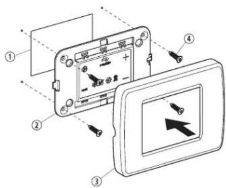
| Po4/ Opis | |
| 1 Izrez | |
| 2 Zaslons a ploča | |
| 3 O vir | |
| 4 'Ija |
E/5 T' stiranD' 4aslona
- Nap the Mode icon to select a mode.
Refer tov* vailable Modes and Options for Operation».
√ L isplay icons illuminate to indicate the selected mode.
Nhe display loc s into the last mode selected arer wve seconds of inactivity? then displays the room temperature. Nhe selected mode |SL remains lit.
* mer 0J seconds of inactivity? the display shows the room temperature and enters the IL1S state.
O] [ displays on the screen to indicate the O] state.
Y hen the display is ma ing a call for heating ^p cooling ^p auT heat ^p or humidity ^p the appropriate Mode indicator blin s for two seconds O ^r and two seconds O[ ] .
. Nap any icon to wave up the control from the O] or II |S state.
U. Nap and hold the Mode icon for three seconds to start a SI SSD state.
√ Mhe display goes dar .
'ormal operation continues.
K. Nap and hold the Mode icon for three more seconds to wave up the control.
F/2/1 Dostupni načini ra( a i ) ogućnosti upotr' b'
| IIona Način ra( a i ,unIcila | ||
 | I ona hlađenja svijetli ada je odabran način rada c OOl ili je jedinica u ci lusu hlađenja u automats om načinu rada ". NOM" Nlc. Radi samo sustav za hlađenje. ' o o olna temperatura padne ispod zadane vrijednosti? sustav se neće automats i prebaciti na grijanje u načinu rada k S' N. | |
 | I ona načina rada za odvla)ivanje svijetli ada je odabran način rada L Sk . MIL I] Ic ' MO' . Naj način rada regulira vlagu ada u plovilu nema ni oga te sprječava da temperatura u abini padne ispod minimalne zadane postav e temperature. Tl2' 1o) r' gulaci2' Olag':b' entilator se vrti UJ min.b Nemperatura zra a uzor uje se i bilje'i.b' a on UJ min započinje ci lus hlađenja oji traje sve do setemperatura ne spusti za QIpc fl Ip] ili do se ci lus hlađenja nenastavi ma simalno jedan sat.b c i lus se ponavlja četiri sata na on postizanja odgovarajućetemperature ili iste a ci lusa hlađenja.Ca r' gulacilu t') p' ratur':b' o je na on UJ min cir ulacije zra a ventilatorom uzora temperature na tvornič i zadanoj postavci od VJ p] FJ oč ili vići od te vrijednosti? započinje ci lus hlađenja radi regulacije vlage.b' o je temperatura ispod VJ p] FJ oč P započinje ci lus grijanja. c i lus grijanja nastavlja se sve do temperatura ne dosge-ne VJ p] FJ pc - ili na on što ci lus grijanja potraje ma simalno jedan sat.b Četiri sata na on postizanja odgovarajuće temperature ili istea ci lusa hlađenja/grijanja ci lus se ponavlja i sva i put utvrđuje je li potrebno hlađenje ili grijanje. UPUTA Samo za sustave L ga ci lus grijanja u načinu rada za odvla)ivanje L Sk . MIL I] Ic " NIO" ne po-reče se a o je o olna temperatura ni) a od KJ p|IKKK pc . No zavojnicu ondenzatora Štiti od smrza-vanja. Sustavi oniğurirani s ele tričnim grijanjempo renut će ci lus grijanja u načinu rada za odvla)i-vanje L Sk . MIL I] Ic " NIO" bez obzira na tempera-turu u abini. UPUTA Samo za sustave L ga ci lus grijanja u načinu rada za odvla)ivanje L Sk . MIL I] Ic " NIO" ne po-reče se a o je o olna temperatura ni) a od KJ p|IKKK pc . No zavojnicu ondenzatora Štiti od smrza-vanja. Sustavi oniğurirani s ele tričnim grijanjempo renut će ci lus grijanja u načinu rada za odvla)i-vanje L Sk . MIL I] Ic " NIO" bez obzira na tempera-turu u abini. | |
 | I ona grijanja svijetli ada je odabran način rada k S' N ili je jedini-ca u ci lusu grijanja u automats om načinu rada '. NOM" Nlc. Ra-di samo sustav grijanja. ' o o olna temperatura poraste iznad za-dane vrijednosti? sustav se neće automats i prebaciti na hlađenje u načinu rada c OOl. | |
 | I ona načina rada ". g k S" N svijetli do radi opcionalni pomoć-ni ele trični grijač. " o o olna temperatura poraste iznad zadane vrijednosti? sustav se neće automats i prebaciti na hlađenje u načinu rada c OOl. | |
 | I ona is ljučenog sustava u načinu rada O|. Svi su ontrolni izlaziis ljučeni. ' a zaslonu piše O]. Sve se postav e spremaju u pos-tojanu memoriju. | |
 | I ona u ljučenog sustava u načinu rada O'. Svi su ontrolni izlazi u ljučeni2 a na zaslonu je naznačeno trenutačno stanje rada. ' azaslonu se pri azuje temperatura u abini. Svi parametri un cioni-raju ao što su postavljeni. | |
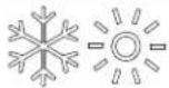 | I one automats og načina rada svijetle ada je sustav u načinu ra-da". NOM" Nlc. te se po potrebi prebacuje na hlađenje ili grijanje a o bi zadrj ao zadanu vrijednost temperature. /ada je od-bran automats i način rada". NOM" Nlc F sustav po potrebi po-reće i grijanje i hlađenje. Svijetle indi atori hlađenja i grijanja c O-Ol i k S" N ili i one hlađenja i pomoćnog grijanja c OOl i". g k S-" N u s ladu sautomats im načinom rada". NOM" Nlc. | |
| OΓ | ||
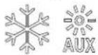 | ||
| IIona Način ra( a i ,un1cija | |
| I onaFanorisni u omogućuje da redom odabire različite brzine ventilatora?o u ljučuje automats u brzinu te brzine od 0 do V IQ z sporol z srednje sporol Z srednja brzina? K z srednje brzo i V z brzol. Brzine ventilatora automats i se odreduju prema zadanim i programiranim vrijednostima. . programs om izborni u postav e D-0 i D-1 odreduju ma simalnu i minimalnu postav u brzine ventilatora.b Brzina ventilatora smanjuje se a o se bli i zadana vrijednost temperature u načinu rada s hlađenjem c OO i nastavlja raditi sporo na on postizanja zadane vrijednosti.b Rad uz automats u brzinu ventilatora mo) e se obrnuti za način rada s grijanjem k S" Na o se parametar D-0l postavi na „rS” v. Cojedinosti potra) ite u odjelj u „Drogramiranje ontrolev.b "utomats i način rada ventilatora utvrđuje potrebnu brzinu ventilatora prema razli ama u temperaturi. Nime se uravnote) u je najučin ovitija regulacija temperature uz sporiji i tiši rad ventilatora. /a o biste odabrali automats i način rada ventilatora? dodirnite i otpustite i onuFando se na zaslonu ne pri a) e ” “a.iUPUTA Dogledajte odjelja „Odabir parametrav. /ada je postavljena gornja i donja granica brzine ventilatora? jedinica automats i prilagodava preosta-le brzine ventilatora i u automats om i u ručnom načinu rada ventilatora. | |
| Ručni način rada ventilatora omogućuje odabir stalne ) eljene brzine ventilatora. Ručno mo) ete postaviti pet brzina ventilatoraa brzo? srednje brzo? srednju brzinu? srednje sporo i sporo. “ a on odabira broj brzine osvijetljen je na zaslonu.b L odirnite i otpustite i onuFana o biste s automats og prešli na ručni način rada ventilatora.b L odirnite i otpustite i onuFana o biste redom birali različite brzine ventilatora? od najsporije do najbr) e.b L odirnite i otpustite i onuFana o biste se vratili na automat-s i način rada ventilatora. | |
| ’ o nije potrebno hlađenje ni grijanje? oristite samo rad ventilatora radi cir ulacije zra a.#. z is ljučeni sustav u načinu rada O|| dodirnite i otpustite i onuFana o biste odabrali ) eljenu brzinu ventilatora.iUPUTA /ada ontrolu u ljučite opcijom O ? ventilator se vraća u automats i način rada". NOM" Nic ili na zadnju ručno odabranu postav u ventilatora. | |
| ci lič i/ ontinuirani način rada ventilatoraMo) ete postaviti da ventilator ontinuirano radi uvije ada je sustav u ljučen ili postaviti da se ci lič i u ljučuje i is ljučuje u s ladu s ci lusima hlađenja ili grijanja.C. L odirnite i pet se undi zadr) ite i onu ventilatoraFan." o je zadana postav a ci lič og načina rada? na zaslonu se pri azuje cec." o je zadana postav a ontinuiranog načina rada? na zaslonu se pri azuje cO". |
F/5 Upotr' ba upra0lDač1' ploč' na 4aslonu
. tablici u nastav u navedene su pojedinosti o ombinacijama i ona za a tivaciju različitih jun cija onrole.
Ko) binacila i1ona Na4i0i i ,un1cila i1ona

Ko) binaciða il ona Na4i0i i ,un1ciða il ona
 | I ona plusaUpi minusaDownDri az vanjs e temperaturea0. Istovremeno dodirnite i one i zadr) ite ih tri se unde.L o dr) ite tu ombinaciju?na zaslonu se naizmjenično pri azuje O. i očitanje vanjs e temperature. | |
 | I ona ventilatoraFani plusaUpDri az temperature mors e vodes0. Istovremeno dodirnite i one i zadr) ite ih tri se unde.L o dr) ite tu ombinaciju?na zaslonu se naizmjenično pri azuje SS i očitanje temperature mors e vode. | |
 | MODE | I one plusaUp2minusaDowni načina radaModeDri az relativne vla) nostia0. Istovremeno dodirnite i one i zadr) ite ih tri se unde.L o dr) ite tu ombinaciju?na zaslonu se naizmjenično pri azuje k S i očitanje relativne vla) nosti. |
 | I ona načina radaModei minusaDown. nesite povijest pogreša aa0. Istovremeno dodirnite i na tri se unde zadr) ite i o-ne do je ontrola is ljučena a o biste otvorili za-pisni povijesti pogreša a.Zaslon mo) e spremiti do osam pogreša a.I . . se theUpand Downicons to view the fault history.U. Istovremeno dodirnite i zadr) ite i one načina radaModei minusa Downna tri se unde a o biste izbri-sali povijest pogreša a.K. Izadite ta o da jedanput dodirnete i onu načina ra-da Mode. | |
 | I ona ventilatoraFani minusa DownSamo L ga pri az mjerača sati rada ompresoraa0. Istovremeno dodirnite i na tri se unde zadr) ite i o de onje o ne do je ontrola is ljučena. ' a zaslonu će se jedanput pri azati ōd k rf a zatim vrijeme rada.I . Izadite ta o da jedanput dodirnete i onu načina ra-da Mode. |
F/6 Progra) iranD' 1ontrol'

UPUTA " o motor ventilatora vašeg limatizacijs og uredaja nije viso obrzins i řk' k's podvojenim onđenzatorom fSc p'već sa zasjenjenim polom fSDp prije upotrebe jedinice programirajte SD u parametar vrste motora ventilatora. Dogledajte odjelja „Drogramiranje ontrolew. SD jedinice prepoznatljive su po izbočenom motoru ventilatora. Sc motor k' jedinice nalazi se unutar ventilatora? a jedinica ima ' NL ili k' ao dio broja modela. Darametar vrste motora ventilatora reprogramirajte samo a o nemate k' ventilator.
Dostav e parametara oriste se za programiranje i /no podećavanje sustava za najučin ovitiji rad unutar instalacije te prilagodbu radnih parametara vaćim speciţčnim potrebama. /ada se nove vrijednosti unesu i memoriraju? tvornič e se postav e briču i novi parametri postaju zadane postav e.
* o capouch ostane bez napajanja radni se parametri zadr) avaju. /ada se napajanje vrati? ontrola nastavlja rad ao Gto je zadnji put programirana.
Zadane tvornič e vrijednosti ontrole pohranjene su u trajnoj memoriji fmemorirane zadane tvornič e postav el te ih mo) ete učitati u slučaju poteš oća u programiranju. Izvorne tvornič i zadane parametre mo) ete vratiti ručno. . odjelj u „Odabir parametaw potra) ite sa) eta parametarađ dopučtene vrijednosti i izvorne tvornič i zadane postav e.
F/6/1 Ula4 u način ra( a 4a progra) iranD'
. ovom su odjelj u navedene detaljne upute za ulaz u način rada za programiranje.
- Lo je ontrola is ljučenaf istovremeno dodirnite i na se undu zadr)ite i one načina rada Mode i plusa Up f+li na zaslonu za pri az. a o biste učli u programs i izborni, a zaslonu se pri azuje D-0.
[ ]
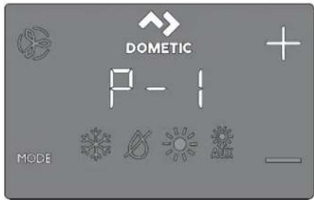
- I onama Up f+1 i Down f- dodite do različitih parametara fD-U° D-I F D-U° itd.h.
U. Lodirnite i onu načina rada Mode a o biste otvorili izborni za podečavanje parametara.
v ' a zaslonu će se naizmjenično pri azivati broj parametra i trenutačna postav a.
K. L odirnite i one Up f+h i Down f-h a o biste podesili postav e parametra.
V. L odirnite i onu načina rada Mode a o biste spremili promjenu parametra i vratili se na programs i izborni.
F/6/2 O(abir para)'tra
. sljedećoj su tablici opisani parametri dostupni za ontrrole zaslona capouch.
| Para) 'tar 1) | 'D8 C- T0orničli | Raspon Oril' (nosti para-4a(ana Ori-) 'tra | |
| 4' (nost | |||
| ničenje ventilatora | x x 9V XV s 9VD-G Mornje ogra- | ||
| Odaberite veći broj za povećanje ili manji broj za smanjenje brzi-ne ventilatora. | |||
| ni- | čenje ventilatora | x x Vj Uj s ZV | |
| Odaberite veći broj za povećanje ili manji broj za smanjenje brzi-ne ventilatora. | |||
| D-U | 'remens a odgoda pre-bacivanja stupnja om-presora | x | QV Vs iq UV s |
| /oristite za instalacije u ojima na istom izvoru napajanja radi više od jednog sustava. Različite odgođe prebacivanja stupnja omogućuju po retanje ompresora u različito vrijeme ada dođe do pre ida napajanja. Razli a između prebacivanja stupnja jedinica mora biti najmanje per se undi. | |||
| D-K | /alibracija senzora tem-perature unutarnjeg zra a | x x O olna tem-peratura O olna temperatura j X'pcFoj [p]h | |
| /alibrira senzor za pri az odgovarajućeg očitanja sobne tempe-rature. Dovećanja postav e izra)ena su u oj ča i a o je ontrola postavljena na pc. | |||
| D-V | Sigurnosna razina | x | U j z minimalna začtitaO z ontinuirano bez pri a-zaI z ontinuirano s pri azomU z četiri pogreć ef potreb-no ponovno po retanje |
| Dogledajte odjelja „Razine sigurnosnog sustavas. | |||
| iUPUTA Raspon parametara O i l primjenjuje se nazaslone s širmverom #40 i starije. | |||
HR000
| Para) 'tar I) | 'D8 C- T0orničli | 4a( ana Ori- 0' (nost | Raspon Oril' (nosti para-) 'tra |
| D-X | /ontrolni ure-đaj za nadzor nis og napo-na | x x | '. S Is ljučeno29V' ~09V' ~ |
| Dostavite rug ugrađenog volumetra oji nadzire ulazni izmjenični napon prije sva og ci lusa hlađenja ili grijanja 9V' ~ili 09V' ~ | |||
| o Za ulaznu snagu od O| | ' le- O| | postavite is ljučivanje na O| ] ili na vrijednost 9V. | |||
| o Za ulaznu snagu od I | J [ ' le- I K] postavite is ljučivanje na O| ] ili na vrijednost 09V. | |||
| D-Z c i lus odleđi-vanja | x'. S | ". SQ z u ljučeno uz tempera-turnu razli u senzora u zas-lonu od Ulpc fV'oj hI z u ljučeno uz tempera-turnu razli u senzora u zas-lonu od Klpc fZ'oj h | |
| Odaberite postav u parametra za značaj u odleđivanja ovisno o tome upotrebljavate li opcionalni senzor temperature ugraden u zaslon. | |||
| b' o upotrebljavate senzor temperature unutarnjeg zra a ili senzor temperature ugraden u zaslon. | |||
| ovaj parameter postavite na O a o biste značaj u odleđivanja u ljučili na O' ili je postavite na O| | a o biste je onemogu-ćili. | |||
| o oristile senzor temperature ugraden u zaslon' odaberite jedan od dva dostupna načina radas. | |||
| O. Dretpostavlja da senzor zaslona sobnu temperaturu mo-j da očitava do Ulpc fVp] h viču no što je stvarna tempera-tura isparivača fstandardnah. | |||
| I. Za e streunije instalacije s pretpostavlja da senzor zaslo-na sobnu temperaturu očitava do Kpc fZ'oj | viču no što je stvarna temperatura isparivača. | |||
| b Dostav u l oristite samo a o postav a 0 ne sprječava stvara-nje leda iz isparivača. | |||
| D-[ Opcionalna zaštita pumpe | x'. S | ". SO' z odabir O| | p' p'qGV| p| fUZZ pc qXV,VV pc h | |
| 'rijednost ovog parametra postavite a o je installiran opcional-ni senzor vode za začtitu pumpe radi provjere temperature za-vojnice ondenzatora te radi is ljučivanja pumpe i ompresora a o temperatura zavojnice poraste iznad programirane vrijednos-ti. Senzor je pri ljučen u izlaznu k | O O. h uričnicu za senzor na upravljač oj ploči.Drogramirajte temperaturu od O | p | p | QV| p | fUZZ pc qXV,VV pc P ovisno o temperaturi mors e vode i vrsti sustava. Dro-citajte upute za instalaciju senzora. Dovećanja postav e izra)ena su u o | ča i a o je ontrola postavljena na pc. | |||
| D-9 Regulacija svjetline zas-lona | x x U 0 finajtamnijel s U finajsvjetli-je | ||
| Za taj parameter zadajte postav u od O do U. tamnoj je abini potrebna postav a G. jar o svijetloj abini potrebna je postav a U. | |||
| D-OJ | Odbir stup-njeva ] ahren-heita ili c elzija | x x ] | ] z pri az.] ahrenheita c z pri az c elzija" z automats i odabir na temelju naponaVJ k z z stupnjevi c elzijaXJ k z z stupnjevi ] ahren-heita |
| Odaberite pc za stupnjeve c elzija fočitanja u c elzijevim stupnje-vima pri azuju se na desetin up' npr. I | H | ph. Zadana je postav a p]. | |||
| Para) 'tar I) | 'D8 C- T0orničli | Raspon Oril' ( nosti para-4a( ana Ori-l' (nost) ) 'tra | |
| D-00 | ci lič a pum-pas s ompre-sorom | x | c ccc c cc z ci lus s ompreso-rom c on z ontinuirano pumpa-nje |
| Odaberite ci lič i ili ontinuirani rad pumpe. b c cc: prođuljuje radni vije pumpe i Čtedi struju naizmjeničnim u ljučivanjem i is ljučivanjem ompresora. b c one programira pumpu ta o da ontinuirano radi uvije ada je sustav u ljučen. | |||
| D-01 | "utomats e reverzne brzi-ne ventilatora tije om grijanja | x x nOr | nOr z uobičajeni rad ventilatora rS] z reverzni rad ventilato-ra u načinu rada s grijanjem k S' N |
| Reverzirajte automats e brzine ventilatora u načinu rada s grijanjem k S' N a o biste poboljćali izlaz topline u hladnijim pod-nebljima. b' o je postavljen na rS] ventilator se ubrzava a o se bli i za-dana vrijednost. 'entilator se prebacuje na najsporiji način ra-da ada se zadana vrijednost postigne ili se ci lus ompresora is ljuči na O)]. b' o je postavljen na nOr ventilator radi na isti način ao i prili-om hlađenja? Čto predstavlja uobičajeni način rada ventilato-ra. | |||
| D-02 | 'acin rada samo s hlađenjem | x | k D k D z toplins a pumpa c l z samo hlađenje |
| Odaberite rad s toplins om pumpom ili samo s hlađenjem. b' o odaberete „k Dv3 jedinica će raditi u zadanom načinu ra-da s toplins om pumpom čto omogućuje hlađenje grijanje u reverznom ci lusu ili fopcionalnoi pomoćno grijanje. b' o odaberete „c lvp jedinica će raditi u načinu rada hlađenjem c OOl ili fopcionalnoi u načinu rada s pomoćnim grijanjem " . g k S' N. b' acin rada " . g k S' N dostupan je samo a o je jedinica opremljena pomoćnim ele tričnim grijačem. | |||
| i UPUTA * o odaberete „clw za ompresor se po-reče odgoda od pet minuta ada se ompresor is-ljučuje pri zadanoj vrijednostp pogreći ili pre idu napajanja. Odgoda od pet minuta počinje odmah na on is ljučivanja ompresora. I ona c OOl za na-cin rada s hlađenjem na zaslonu bljes a jedanput u se undi pet minuta ili tije om preostalog vremena do iste a pet minuta na on završet a zadnjeg ci lu-sa. " o razdoblje odgode od pet minuta prode pri-je no što ompresor treba djelovati' ompresor se u ljučuje bez odgode. | |||
| D-0K | Odobir moto-ra ventilatora | x x Sc | Sc z motor ventilatora s podvojenim ondenzato-rom SD z motor ventilatora sa zasjenjenim polom |
| Dostavite na Sc na s lop i limatizacijs ih uredaja s viso obrzin-s im ventilatorom. Dostavite na SD a o vača jedinica ima motorventilatora sa zasjenjenim polom. Dogledajte odjelja „Programiranje ontrolex. | |||
| D-0V | 'račanje tvor-nič i zadanih postav i | x x nOr | rSh z vračanje zadanih pos-tav i nOr z uobičajeno |
| /a o biste sve programs e parametre vratili na početne postavej taj parametar postavite na rSN. Nime sve programibilne parametre vraćate na tvornič i zadane vrijednosti. | |||
| Para) 'tar I) 'D8 C- T0orničli | Raspon Oril' ( nosti para-4a( ana Ori- ) 'tra" ( nost | |
| D-IX k idronič iventil za vodusilom otvoren | x nOr | OEn z ventil silom otvorennOr z uobičajeni rad |
| Otvorite ventil za vodu a o biste iz sustava ispustili zra .b ODna prisilno otvara ventil na četiri sata do je ontrola is ljučena. Čremočćivanje ventila ot azuje se a o u ljučite ontrolu ili se tije om tog čterverosatnog razdoblja izmjenično napaja-nje pre ine.b nOra vraća ventil u uobičajeni način rada. | ||
| D-5Z Razli a u tem-peraturi vode | x 0V p) f[ pc: Ulpc do 0Klpc fVlp] do | Vj ] | |
| Dostavite temperaturnu razli u između temperature o olnog zra-a i temperature hidronič e vode oja upravlja ventilom za vodu." of primjericef odaberete OJ p) fCI P1 pcif ventil se otvara a-da je temperatura vode za OJ p) fCI P1 pcni) a od o olne tem-perature u načinu rada s hlađenjem i za OJ p) fCI P1 pcviša od o olne temperature u načinu rada s grijanjem.Da) ljivim odabirom temperaturne razli e mo) ete u potpunosti is oristiri resurse za grijanje i hlađenje u plovilu. * o je? primjeri-ce2 a tivan način rada s hlađenjem uz vrijednost OJ p) fCI P1 pcif ventil će se otvoriti a o bi omogućio nečto hlađenja do se hi-dronič i sustav spučta prema potrebnoj temperaturi. | ||
| D-6[ Dostavljanje brojača vre-mena za čiće-cenje/zamje-nu ūltra za zra | x x ] Dri azuje vrijeme oje je | prote lo fu satima T0J ot-ad je mjerač vremena po-renut ili vraćen na početnu vrijednost. |
| Dostavite podsjetni za čićejenje ili zamjenu ūltra za zra .Ar/FLrat o bljes a na [SL zaslonu sva ih O] se undi do poničtavanja.b. neseni parametar predstavlja taj broj puta OJ sati. Odaberite broj radnih sati sve do se ne pojavi podsjetni za ūltar.za parametar mo) ere odabrati vrijednost od OJ f0J ] sati do | VJ | fl VJ ] satil.b lodimite i onu minusaDown a o biste vrijednost vratili na j ponovno po renuli brojač vremena i izbrisali podsjetni .UPUTA L ometic preporučuje da ūltar za zra pro-vjerite najmanje sva ih VJ ] sati rada. | ||
| D-59 'rijednost i ponovno pos-tavljanje bro-jača vreme-na za čiće- nenje/zamjenu ūltra | x x ] Dri azuje vrijeme oje je | prote lo fu satima T0J ot-ad je mjerač vremena po-renut ili vraćen na početnu vrijednost. |
| Dri az trenutačno prote log vremena fu satima T0J ot ad je mje-rač vremena po renut ili vraćen na početnu vrijednost. /ada vrijednost tog parametra dosegne vrijednost postavljenu u parame-tru D-6[ Par/FL bljes a na zaslonu sva ih OJ se undi do poničta-vanja. L odirnite i onu minusaDown a o biste vrijednost vratili na J p ponovno po renuli brojač vremena i izbrisali podsjetni . | ||
| c'' sabirni-cu | x x dIS fIL jedini-ce z V9 fna-on omogu-ćivanja te is-ljučivanja i ponovnog u ljučivanja napajanja# | | s | VVD-I | IL jedinice za |
| Svim jedinicama s ugrađenim adapterom za c'' sabirnicu omogućuje da se zajedno umre) e i omuniciraju međusobno ili sa sustavom c'' sabirnice plovila fu ne im slučajevima uz dodatnu opremu za prevođenjeh.b /a o biste omogućili tu'un ciju# parametar postavite na J.b Custie da se zaslon ponovno is ljuči na OJ].b Is ljučite pa ponovno u ljučite sustav.b /ada se sustav u ljuči# IL jedinice za c'' sabirnicu bit će postavljen na V9.b. nesite broj IL -a jedinice za c'' sabirnicu. | ||
| Para) 'tar I) | 'D8 C- T0omicli | 4a( ana Ori-l' (nost | Raspon Orib' (nosti para-) 'tra |
| c'' sabirnicu | x x vl fna on | ] s | VVD-I G Mrupni IL za omogućivanja te is ljučivanja i po-novnog u ljučivanja napa-janja' | |
| Svim jedinicama s ugrađenim adapterom za c'' sabirnicu omogućuje da se grupiraju u mre) ni sustav i omuniciraju sa sustavom c'' sabirnice plovila fu ne im slučajevima uz dodatnu opremu za prevođenjel.b /ada je pri azan parametar D-I J P grupni IL pri azuje 0.b /ada je IL jedinice za c'' sabirnicu postavljen na J te se napajanje is ljuči i ponovno u ljučif grupni IL za c'' sabirnicu po zadanim je postav ama Vl .b Izvršite ora e u parametru D-I | > a zatim unesite broj grupnog IL -a za c'' sabirnicu. | |||
| D-I I /alibracija napona | x x Izmjenični | Codesite u s ladu s točnim očitanjem napona. | |
| napon | |||
| Dri azuje a tualnu vrijednost napona oju očitava tis ana pločica sa strujnim rugovima. /alibracija tog parametra pru) a precizniju razinu napona prili om izračuna nís og napona za parametar D-X.Za podečavanje oristite pouzdani voltmetar. | |||
| D-I U Nemperaturnarazli a zadane vrijednosti | x x | | G z razli a od JFXpc fOlp|h1 z razli a od Olp cOlp|h | |
| Nemperaturnu razli u postavite u stupnjevima ]ahrenheita za sve načine radas". NOM" Mlc za automats i način rada3 c OOl za hlađenjeP k S" N za grijanje ili". g k S" N za pomoćno grijanje.Dogledajte odjelja „Odabir načina rada ontrolev.b Qa odr)ava sobnu temperaturu na j J FXpc fCp] < od ) eljene za-dane vrijednosti.b I a odr)ava sobnu temperaturu na j Cpc fi 'p] < od ) eljene za-dane vrijednosti. | |||
| D-I K Minimal-na tempe-ratura nači-na rada L-S-k. MIL I] Ic * MIO za odvla) ivanje | x | VJ p] fOJ pc: KJ ? J p]IQ ZV? J p]fK.KK pc iQ I U.[ [ pc] | |
| Dostavite minimalnu sobnu temperaturu lu stupnjevima ] ahren-jeitan za oju način rada za odvla) ivanje L Sk. MIL I] Ic * NIO' po reće ci lus hlađenja radi u lanjanja vlage iz zra a." o sobna temperatura padne ispod te postav e parametraf način rada za odvla) ivanje L Sk. MIL I] Ic * NIO' po reće ci lus grijanja. Dogledajte odjelja „Odabir načina rada ontrolev. | |||
| D-I V Nemperatur-na razli a za automats u brzinu ventilatora | x x | p] fO pc: Q p] do U p] || X pc do | pc'h | ||
| Dostavite postupnu razli u fs umulativnim oracima' između o olne temperature i zadane vrijednosti temperature pri ojoj će se brzina ventilatora povećati na sljedeću brzinu. | |||
| iUPUTA k istereza od JFXpc fOlp] u razlici automat-s e brzine ventilatora sprječava promjenu brzine u slučaju promjene sobne temperature. Osim togal'oba programs a parametra D-OI i D-I U utjeću na rad automats e brzine ventilatora. | |||
| D-I X Mornja grani-ca tempera-ture ulaznog zra a | x x | '. S | '. S9V a]IQ GK a] u oracima od V p#UV pc iQ XJ pc u oracima od I F[ ph |
HR000
| Para) 'tar I) 'D8 C- T0orničli | Raspon Orl' ( nosti para-4a( ana Ori- ) 'tra" (nost | |
| Dostavite ma simalno dopučtenu temperaturu iz ispuha ulaznog zra a.b Omogućivanje tog parametra nema učin a o parametar D-1 [ nije omogućen i postavljen na Sn'.b Za upotrebu tog parametra u proto ulaznog zra a2 odmah iza ispuha iz ventilatora? mora biti postavljen senzor O' N.b 'ačin rada za grijanje k S' N is ljučuje se a o temperatura tog senzora premačuje postav u. 'ačin rada za grijanje k S' N ponovno se u ljučuje a o je zadovoljena histereza od X[pc f] [p] ili je napajanje prebačeno na ontrolu i temperatura na senzoru O' N manja je od postav e2 ali jo6 uvije unutar histereze. " o dođe do te pogre6 ef pri azuje se S" k.b Dri a) ite temperaturu ispuha ta o da istovremeno dodirnete i one plusa Up i minusa Down fisto ao za pri az temperature vanjs og zra al. | ||
| D-1 Z Odgoda sta-nja mirovanja | x x Oj se undi V s'q OJ s fu oracima od V s' | |
| Dostavite vrijeme odgode prije ulas a zaslona u stanje mirovanja.Dogledajte odjelja „Odabir načina rada ontrolev. I onama Up ili Down povećajte ili smanjite vrijeme odgode do mirovanja. | ||
| nje pomoć-nog grijanja | x x dIS dIS/Sn' O-1 | Omogućiva- | |
| Omogućite rad opcionalnog pomoćnog ele tričnog grijača. ' o je ugraden pomoćni ele trični grijač? promijenite ovu postav u u Sn' a o biste pomoćnim ele tričnim grijačem mogli ru ovati neovisno o grijanju u reverznom ci lusu. . apli acijama sustava L g ispub iz pomoćnog ele tričnog grijanja i ompresora na upravljač oj ploči rade istovremeno samo ada je a tivna'un cija odvla) ivanja. Dogledajte „Omogućivanje relativne vla) nostis u ovoj tablici. | ||
| nje relativne vla) nosti | x x ". S O)] / V] s [ ] D-1 9 Omogućiva- | |
| Omogućite opcionalni senzor za ombinaciju sobne temperature / relativne vla) nosti. No sustavu omogućuje odvla) ivanje pomoćnim ele tričnim grijanjem fa o je ugraden i omogućen pomoćni ele trični grijač! ada vlaga u abini poraste iznad odabra-ne relativne vla) nosti IR'.b Za apli acije sustava L ga relativna vla) nost omogućena. " o je opcionalni senzor za ombinaciju sobne temperature / relativne vla) nosti povezan s upravljač om pločom i ot rije da se vlaga povećalaf radno vrijeme ompresora produljit će se tao da radi do Q p] f(ZP) I pc hi) e od zađane vrijednosti a o bi u lonio vlagu. " o je ugraden pomoćni ele trični grijačF on se ci lič i u ljučuje i is ljučuje radi odr) avanja zadane vrijednosti do ompresor radi dulje radi odvla) ivanja.UPUTA Mo) e doći do razdoblja pre lapanja a o su ompresor i pomoćni ele trični grijač istovremeno u ljučeni. Naj se ci lus nastavlja sve do relativna vla) nost u abini ne padne ispod zada-ne vrijednosti vla) nosti. Raspon podešavanja relativne vla) nosti iznosi Vj t lq [ ] t R'.b Za apli acije sustava c Y a relativna vla) nost omogućena. " o je senzor za ombinaciju sobne temperature / relativne vla) - nosti povezan s upravljač om pločom? ova značaj a sustavu omogućuje odvla) ivanje ele tričnim grijanjem fa o je ugra- den i omogućen pomoćni ele trični grijač! ada vlaga u abini poraste iznad zadane vrijednosti vla) nosti. Domoćni ele trični grijač naizmjence se u ljučuje i is ljučuje a o bi odr) ao za-danu vrijednost do se zaobilazni ventil otvara a o bi hladna voda u petlji mogla ući u zavojnicu regulatora zra a radi odvla-) ivanja. Naj se proces nastavlja sve do relativna vla) nost u abini ne padne ispod zadane vrijednosti vla) nosti. " o pomoćni ele trični grijač nije ugrađenF vrijeme u ljučenja zaobilaz-nog ventila produljuje se ta o da radi do Q p] f(ZP) I pc hi) e od zadane vrijednosti. Naj se ci lus nastavlja sve do relativna vla) nost u abini ne padne ispod zadane vrijednosti vla) nosti.Raspon podešavanja relativne vla) nosti iznosi Vj t lq [ ] t R'. | ||
| Para) 'tar I) D8 C- T0omicli | Raspon Orib' (nosti para-4a( ana Ori- ) 'trab' (nost | ||
| D-UJ Dodečavanjedonje granicemors e vode | x KJ p] | UVPj p]lq VJ p]fK?KK pc fQ,XX pc lq Qj pc h | |
| " o je opcionalni senzor za podečavanje donje granice mors ewode spojen na l-pins i izlazni pri ljuča k l O Out na upravljač-oj pločif sustav postavite ta o da se s grijanja reverznim ci lusom prebaci na pomoćno ele trično grijanje fa o je pomoćniele trični grijac ugrađen i omogućeni.b L o prilagodbe dolazi ada temperatura mors e vode padneispod KJ p] fKKK pc h i grijanje reverznim ci lusom radi većdulje od pet minuta. /ada temperatura mors e vode poraste za U p] fCXPO pc h iznad zadane vrijednosti temperature nasenzoru za podečavanje donje granice? sustav se vraća na grijanje reverznim ci lusom.b ' o pomoćni ele trični grijac nije ugrađenf sustav se is ljučuje i hljes a LO pa SE a o temperatura mors e vode pad-ne ispod KJ o] fK?KK pc h zadanoli. /ada temperatura mors ewode poraste za U p] fCXPO pc h iznad zadane vrijednosti tem-perature na senzoru za podečavanje donje granice? sustav seautomats i vraća na grijanje reverznim ci lusom i prestaje bljes ati LO pa SE. | |||
| D-UQ /alibracijasenzora vla)-nosti | x x Relativnavla) nost u o ru) e-vla) nost u o ru) enju | Relativna vla) nost u o ru) e-nju j QJ t | |
| /alibrirajte senzor za ombinaciju sobne temperature / relativnevla) nosti za pri az točnog očitanja vla) nosti u prostoriji.UPUTA Ova je postav a primjenjiva samo na verzijusoštvera #KI i novije. | |||
| D-UJ /alibracijasenzora tem-perature ulaz-ne vode | x x | c Y z tem-peratura ohlađene vo-de iz dovodaL g z tempe-ratura zavoj-nice onden-zatora ili mor-s e vode | c Y z temperatura ohlađe-ne vode iz dovoda j XlpcfQJ |p|hL g z temperatura zavojnice ondenzatora ili mors e vo-de j Xlpc fQJ |p]· |
| /alibrirajte senzor temperature vode na izlazu fl. gli ulazu fc.Yt za pri az točnog očitanja temperature vode. Dovećanja postav e izra)ena su u p] ča i a o je ontrola postavljena na pc.UPUTA Ova je postav a primjenjiva samo na verziju so'tvera #KI i novije. | |||
| D-UU /alibracijasenzora O' N | x x ' anjs a o ol-na tempera-tura | 'anjs a o olna temperaturaj Xlpc fQJ |p|h | |
| /alibrirajte senzor temperature vanjs og zra a za pri az točnog očitanja temperature vanjs og zra a. Dovećanja postav e izra)ena su u p] ča i a o je ontrola postavljena na pc.UPUTA Ova je postav a primjenjiva samo na verziju so'tvera #KI i novije. | |||
F/6/5 I4la4 i4 načina ra( a 4a progra) iranD'
. ovom je odjelj u opisano a o izaći iz načina rada za programiranje.
/a o biste ručno izagli iz programs og izborni a³ istovremeno dodirnite i zadr) ite i one Up f+ i načina rada Mode na tri se unde do se ne pri a) e sobna temperatura. protivnom zaslon automats i izlazi iz programs og izborni a na on OJ se undi nea tivnosti.
‘ erzija sorvera ontrrole [primjerice „K] oh pri azuje se na zaslonu jednu se undu prije ručnog ili automats og izlas a iz načina rada za programiranje. /ontrola se na on izlas a is ljučuje.
F/6/6 I('nti,i1aciDa 1o( o0a progra) s1ih pogr' šala
□

/a o bi se jedinica začtitila određena stanja pogreš e a tiviraju blo adu oja is ljučuje ontrou. /ontrola se neće ponovno po renuti do se pogreš a ne ot loni. rsta blo ade povezane s pogreš om ovisi o vrsti ot rivene pogreš e fpogledajte tablicu /odovi pogreša a i statusa u nastav ur u ombinaciji s razinom začtite fpogledajte tablicu Razine sigurnosnog sustava u nastav uh programiranom u parametru D-V fpogledajte odjelja „Odabir parametravh.
Ko( o0i pogr' ša1a i statusa
| Ko( Opis D8 C- | ||
| k D) Dogre6 a viso otlacne s lop ea naznačuje viso la rashladnog sredstva. Na pogreš a nije primjenjiva u načinu rada s grijanjem k S' N. | x | |
| |D) Dogre6 a nis otlacne s lop ee naznačuje niza tla rashladnog sredstva. Ova pogre- ć a ima odgodu is ljučivanja od tri minute fza zaslone s čirmverom #41 i novijeh. | x | |
| DI) Dogre6 a nis og proto a u pumpia nazna- čuje viso u temperaturu vode u zavojnici za ondenzaciju ili niza proto u pumpi. | x | |
| II/– – ' aznačuje var senzora vode u petlji. x | ||
| IS/– – . nutarnji senzora naznačuje očtećenje sen- zora temperature ugrađenog u zaslon. | x | x |
| " r/) | ' aznačuje iste brojača vremena za zamje- nu Íltra za zra . | x | x |
| S" k ' aznačuje gornju granicu temperature ulaznog zra a. | x | x |
| SID ' aznačuje način rada u mirovanju ili za lju- čanom stanju. tim načinima rada gumbi ne ûun cioniraju. | x | x |
| |O/SS ' aznačuje donju granicu mors e vode. x x | ||
| |O/“ c Dogre6 a nis og napona naznačuje niza napon. Ova pogreš a nudi dodatnu začut- tu ompresora i dijelova unutar sustava ti- je om uvjeta nis og napona i privremenih pre ida napajanja: b /ada se ompresor po rene' ontrol- ni uređaj za nadzor nis og napona pro- vjerava ulazni izmjenični napon. " o je napon ni) i od navedene postav e f9V ' ~/09V ' ~ki tri minute ostane is- pod te vrijednostif sustav se is ljučuje i pri azuje se pogreš a o nis om izmje- ničnom naponu. b Dogreš a traje sve do ulazni iz- mjenični napon ne poraste iznad 9V ' ~/09V ' ~ Dotom se Łd pogre- ć e | O/“ c automats i briće i započinje ci lus hlađenja ili grijanja. | x | x |
Ra4in' sigurnosnog susta0a
| Ra4ina | Opis | Sa) o D8 |
| J | Razina sigurnosnog sustava J a privremena začita od va-ra ^b ograničena na pet minuta. ' a on pet minuta sustav se automats i prebacuje na razinu U šamo za zaslone s čirmverom #KJ i novijeh. Drul a minimalnu sigurnosnu za- čritu te se ne preporučuje.b Ot riva se i pri azuje samo pogreš a IS/— .b /ontrola se is ljučuje i neće se ponovno po renuti do se pogreš a ne ot loni.b /ontrola se na on poprav a ponovno po reće na on odgode od dvije minute. | x |
| Q | Razina sigurnosnog sustava C šamo za zaslone s čirmve- rom #KJ i starijelke obuhvaća sigurnosne radnje prijačnje razine i ot riva sve ostale pogreš e ^b ali se one ne pri azu- ju.b Sustav se is ljučuje na dvije minute ili do u lanjanja pogreš e ^b ovisno o tome što potraje dulje.b Sustav se ponovno po reće na on u lanjanja pogre- ^c e. | |
| I | Razina sigurnosnog sustava I šamo u zaslonima s čirmve- rom #KJ i starijimata obuhvaća sigurnosne radnje prijač- njih razina i pri azuje sve ostale pogreš e.b Sustav se is ljučuje na dvije minute ili do u lanjanja pogreš e ^b ovisno o tome što potraje dulje.b Sustav se ponovno po reće na on u lanjanja pogre- ^c e. | |
| U | Razina sigurnosnog sustava Ua obuhvaća sigurnosne rad- nje prijačnjih razina te se sustav is ljučuje na on četiri uzastopne pogreš e k D] P1D] ili D]. Blo ada se usto mo- le u loniti.b Sustav se is ljučuje na dvije minute ili do u lanjanja pogreš e ^b ovisno o tome što potraje dulje.b /a o biste u lonili blo adu ^b udite u način rada O] s is ljučenim sustavom. Dotom se vratite u način rada O' s u ljučenim sustavom. |
G NaOigaciDs1o stablo
. ovom je odjelj u pri azana navigacija roz izborni e za ontrolu capNouch.
□
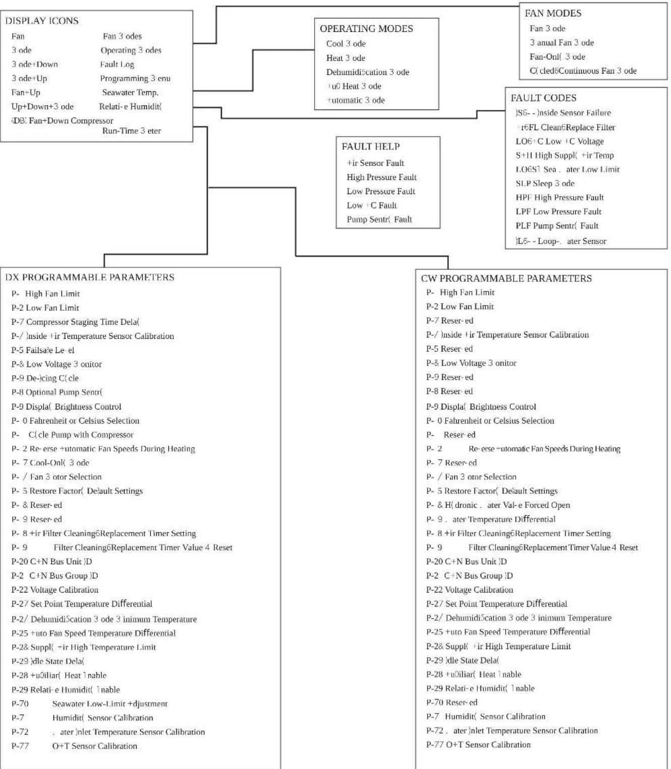
flowchart
graph TD
    A["DISPLAY ICONS"] --> B["FAN"]
    A --> C["OPERATING MODES"]
    A --> D["FAULT CODES"]
    A --> E["DX PROGRAMMABLE PARAMETERS"]
    A --> F["CW PROGRAMMABLE PARAMETERS"]

    B --> B1["Fan Fan 3 odes"]
    B --> B2["Fan 3 ode Operating 3 odes"]
    B --> B3["3 ode+Down Fault Log"]
    B --> B4["3 ode+Up Programming 3 enu"]
    B --> B5["Fan+Up Seawater Temp."]
    B --> B6["Up+Down+3 ode Relati-e Humidit"]
    B --> B7["DB Fan+Down Compressor Run-Time 3 eter"]

    C --> C1["Cool 3 ode"]
    C --> C2["Heat 3 ode"]
    C --> C3["Dehumiditation 3 ode"]
    C --> C4["u0 Heat 3 ode"]
    C --> C5["+utomatic 3 ode"]

    D --> D1["FAULT HELP"]
    D --> D2["High Pressure Fault"]
    D --> D3["Low Pressure Fault"]
    D --> D4["Low +C Fault"]
    D --> D5["Pump Sentr Fault"]

    E --> E1["P- High Fan Limit"]
    E --> E2["P-2 Low Fan Limit"]
    E --> E3["P-7 Compressor Staging Time Dela"]
    E --> E4["P-/ inside +ir Temperature Sensor Calibration"]
    E --> E5["P-5 Failsafe Le el"]
    E --> E6["P-& Low Voltage 3 onitor"]
    E --> E7["P-9 De-)cing C'cle"]
    E --> E8["P-8 Optional Pump Sentr"]
    E --> E9["P-9 Displa' Brightness Control"]
    E --> E10["P-0 Fahrenheit or Celsius Selection"]
    E --> E11["P- C'cle Pump with Compressor"]
    E --> E12["P-2 Re-erse +utomatic Fan Speeds During Heating"]
    E --> E13["P-7 Cool-Onl 3 ode"]
    E --> E14["P- / Fan 3 otor Selection"]
    E --> E15["P-5 Restore Factor' Default Settings"]
    E --> E16["P- & Reser-ed"]
    E --> E17["P- 8 +ir Filter Cleaning6Replacement Timer Setting"]
    E --> E18["P- 9 Filter Cleaning6Replacement Timer Value 4 Reset"]
    E --> E19["P-20 C+N Bus Unit |D"]
    E --> E20["P-2 C+N Bus Group |D"]
    E --> E21["P-22 Voltage Calibration"]
    E --> E22["P-27 Set Point Temperature Differential"]
    E --> E23["P-2/ Dehumiditation 3 ode 3 inimum Temperature"]
    E --> E24["P-25 +uto Fan Speed Temperature Differential"]
    E --> E25["P-28 Suppl' -ir High Temperature Limit"]
    E --> E26["P-29 dle State Dela"]
    E --> E27["P-28 +u0iliar' Heat 1 nable"]
    E --> E28["P-29 Relati-e Humidit' 1 nable"]

    F --> F1["FAN MODES"]
    F --> F2["FAN 3 ode"]
    F --> F3["3 anual Fan 3 ode"]
    F --> F4["Fan-Onl 3 ode"]
    F --> F5["C' cled6Continuous Fan 3 ode"]

    G["FAULT CODES"] --> G1["S6-- inside Sensor Failure"]
    G --> G2["rFL Clean6Replace Filter"]
    G --> G3["LO6+C Low +C Voltage"]
    G --> G4["S+H High Suppl' +ir Temp"]
    G --> G5["LO6S' Sea , after Low Limit"]
    G --> G6["SLP Sleep 3 ode"]
    G --> G7["HPF High Pressure Fault"]
    G --> G8["LPF Low Pressure Fault"]
    G --> G9["PLF Pump Sentr Fault"]
    G --> G10["L6-- Loop-, after Sensor"]

    H["CW PROGRAMMABLE PARAMETERS"] --> H1["P- High Fan Limit"]
    H --> H2["P-2 Low Fan Limit"]
    H --> H3["P-7 Reser-ed"]
    H --> H4["P-/ inside +ir Temperature Sensor Calibration"]
    H --> H5["P-5 Reser ed"]
    H --> H6["P-& Low Voltage 3 onitor"]
    H --> H7["P-9 Reser ed"]
    H --> H8["P-8 Reser ed"]
    H --> H9["P-9 Displa' Brightness Control"]
    H --> H10["P-0 Fahrenheit or Celsius Selection"]
    H --> H11["P- Reser ed"]
    H --> H12["P- 2 Re-erse +utomatic Fan Speeds During Heating"]
    H --> H13["P- 7 Reser ed"]
    H --> H14["P- / Fan 3 otor Selection"]
    H --> H15["P- 5 Restore Factor' Default Settings"]
    H --> H16["P- & H'dronic , after Val-e Forced Open"]
    H --> H17["P- 9 . after Temperature Differential"]
    H --> H18["P- 8 +ir Filter Cleaning6Replacement Timer Setting"]
    H --> H19["P- 9 Filter Cleaning6Replacement Timer Value 4 Reset"]
    H --> H20["P-20 C+N Bus Unit |D"]
    H --> H21["P-2 C+N Bus Group |D"]
    H --> H22["P-22 Voltage Calibration"]
    H --> H23["P-27 Set Point Temperature Differential"]
    H --> H24["P-2/ Dehumiditation 3 ode 3 inimum Temperature"]
    H --> H25["P-25 +uto Fan Speed Temperature Differential"]
    H --> H26["P-28 Suppl' +ir High Temperature Limit"]
    H --> H27["P-29 dle State Dela"]
    H --> H28["P-28 +u0iliar' Heat 1 nable"]
    H --> H29["P-29 Relati-e Humidit' 1 nable"]

    I["CW PROGRAMMABLE PARAMETERS"] --> I1["P- High Fan Limit"]
    I --> I2["P-2 Low Fan Limit"]
    I --> I3["P-7 Reser ed"]
    I --> I4["P-/ inside +ir Temperature Sensor Calibration"]
    I --> I5["P-5 Reser ed"]
    I --> I6["P-& Low Voltage 3 onitor"]
    I --> I7["P-9 Reser ed"]
    I --> I8["P-8 Reser ed"]
    I --> I9["P-9 Displa' Brightness Control"]
    I --> I10["P-0 Fahrenheit or Celsius Selection"]
    I --> I11["P- Reser ed"]
    I --> I12["P- 2 Re-erse +utomatic Fan Speeds During Heating"]
    I --> I13["P- 7 Reser ed"]
    I --> I14["P- / Fan 3 otor Selection"]

    J["CW PROGRAMMABLE PARAMETERS"] --> J1["P- High Fan Limit"]
    J --> J2["P-2 Low Fan Limit"]
    J --> J3["P-7 Reser ed"]
    J --> J4["P-/ inside +ir Temperature Sensor Calibration"]
    J --> J5["P-5 Reser ed"]
    J --> J6["P-& Low Voltage 3 onitor"]
    J --> J7["P-9 Reser ed"]
    J --> J8["P-8 Reser ed"]

    K["CW PROGRAMMABLE PARAMETERS"] --> K1["P- High Fan Limit"]

    L["CW PROGRAMMABLE PARAMETERS"] --> M1["P- High Fan Limit"]

    M1 --> M2["P-2 Low Fan Limit"]

    N["CW PROGRAMMABLE PARAMETERS"] --> N1["P- High Fan Limit"]

    O["CW PROGRAMMABLE PARAMETERS"] --> P1["P- High Fan Limit"]

    Q["CW PROGRAMMABLE PARAMETERS"] --> R1["P- High Fan Limit"]

    S["CW PROGRAMMABLE PARAMETERS"] --> S1["P- High Fan Limit"]

    T["CW PROGRAMMABLE PARAMETERS"] --> T1["P- High Fan Limit"]

    U["CW PROGRAMMABLE PARAMETERS"] --> V1["P- High Fan Limit"]

    W["CW PROGRAMMABLE PARAMETERS"] --> W1["P- High Fan Limit"]
10 U1lanDanD' s) 'tnDi
DOMETIC AUSTRALIA PTY LTD
1 JOHN DUNCAN COURT
VARSITY LAKES, QLD, 4227
1800-212-121
DOMETIC NEW ZEALAND LTD
373 NEILSON STREET
PENROSE, AUCKLAND, 1061
+64 9 622 1490
HR000
Sa) o AustraliDa
'aoi arti li dolaze s jamstvima oja se ne mogu is ljučiti prema "ustrals om za onu o začiti potročača. Imate pravo na zamjenu ili povrat novca za veli i var te na nadu za bilo a av razumno predvidiv gubita ili Četu. Na oder imate pravo na poprava ili zamjenu arti ala a o arti li ne ispunjavaju prihvatljivu razinu valitete i var ne znači veli i var.
Sa) o No0i C' lan(
E A ontaD
E/5 Opsiyon' l bir s' nsHrJ n) ont' ' ( il) ' si
natural_image
Diagram of an electronic device showing a connector with an attached cable (no text or symbols present)| Konu) A(1 | |
| 1 Montaj božluğu | |
| 2 S ran paneli | |
| 3 /apa | |
| 4 ida |
E/5 E1ram t' st ' t) '
- Nap the Mode icon to select a mode.
Refer tov* vailable Modes and Options for Operationa.
√ L isplay icons illuminate to indicate the selected mode.
Nhe display loc s into the last mode selected arer iwe seconds of inactivity? then displays the room temperature. Nhe selected mode | SL remains lit.
* mer 0j seconds o3 inactivityf the display shows the room temperature and enters the IL1S state.
O]] displays on the screen to indicate the O]] state.
Y hen the display is ma ing a call for heating cooling auT heat or humidity the appropriate Mode indicator blin s for two seconds O' and two seconds O].
[ . Nap any icon to wave up the control (from the O)] or IL |S state.
U. Nap and hold the Mode icon for three seconds to start a SI SSD state. √ Mhe display goes dar .
'ormal operation continues.
K. Nap and hold the Mode icon for three more seconds to wave up the control.
F/2/1 A'0cut 0alis) a) o(lari 0's'0'n'1l'ri
Si) g' Ao( 0' işl' 0i

C( cled6Continuous Fan 3 ode
FAULT CODES
)S6- - )inside Sensor Failure
r6FL Clean6Replace Filter
LO6+C Low+C Voltage
S+H High Suppl(+ir Temp
LO651 Sea. later Low Limit
SLP Sleep 3 ode
HPF High Pressure Fault
LPF Low Pressure Fault
PLF Pump Sentr( Fault
)L6--Loop-.ater Sensor
DX PROGRAMMABLE PARAMETERS
P- High Fan Limit
P-2 Low Fan Limit
P-7 Compressor Staging Time Dela
P-/ inside +ir Temperature Sensor Calibration
P-5 Failsale Le-el
P-& Low Voltage 3 onitor
P-9 De-)cing C(cle
P-8 Optional Pump Sentr(
P-9 Displa( Brightness Control
P- 0 Fahrenheit or Celsius Selection
P- C(cle Pump with Compressor
P- 2 Re- erse +utomatic Fan Speeds During Heating
P-7 Cool-Onl(3ode
P-/Fan 3 otor Selection
P- 5 Restore Factor( Default Settings
P- & Reser-ed
P-9 Reser-ed
P- 8 +ir Filter Cleaning6Replacement Timer Setting
P-9 Filter Cleaning6Replacement Timer Value 4 Reset
P-20 C+N Bus Unit |D
P-2 C+N Bus Group |D
P-22 Voltage Calibration
P-27 Set Point Temperature Differential
P-2/ Dehumidi5cation 3 ode 3 inimum Temperature
P-25 +uto Fan Speed Temperature Differential
P-2& Suppl(-ir High Temperature Limit
P-29)dle State Dela(
P-28 +uOiliar( Heat 1nable
P-29 Relati-e Humidit( 1nable
P-70 Seawater Low-Limit +djustment
P-7 Humidit(Sensor Calibration
P-72 .ater Inlet Temperature Sensor Calibration
P-77 O+T Sensor Calibration
CW PROGRAMMABLE PARAMETERS
P- High Fan Limit
P-2 Low Fan Limit
P-7 Reser-ed
P-/ inside +ir Temperature Sensor Calibration
P-5 Reser ed
P-& Low Voltage 3 onitor
P-9 Reser-ed
P-8 Reser-ed
P-9 Displa( Brightness Control
P- 0 Fahrenheit or Celsius Selection
P- Reser-ed
P- 2 Re- erse -utomatic Fan Speeds DuringHeating
P-7 Reser-ed
P- / Fan 3 otor Selection
P- 5 Restore Factor( Default Settings
P- & H(dronic. later Val-e Forced Open
P-9. later Temperature Differential
P- 8 +ir Filter Cleaning&Replacement Timer Setting
P- 9 Filter Cleaning6Replacement Timer Value 4 Reset
P-20 C+N Bus Unit D
P-2 C+N Bus Group |D
P-22 Voltage Calibration
P-27 Set Point Temperature Differential
P-2/ Dehumidi5cation 3 ode 3 inimum Temperature
P-25 +uto Fan Speed Temperature Differential
P-2& Suppl( +ir High Temperature Limit
P-29 |dle State Dela(
P-28 +uOiliar( Heat Enable
P-29 Relati-e Humidit( 1nable
P-70 Reser-ed
P-7 Humidit(Sensor Calibration
P-72. ater Inlet Temperature Sensor Calibration
P-77 O+T Sensor Calibration
DOMETIC AUSTRALIA PTY LTD
1 JOHN DUNCAN COURT
VARSITY LAKES, QLD, 4227
1800-212-121
DOMETIC NEW ZEALAND LTD
373 NEILSON STREET
PENROSE, AUCKLAND, 1061
+64 9 622 1490
Yalni4ca A0ustralya
Our goods come with guarantees that cannot be eTcluded under the "australian consumer law, eou are entitled to a replacement or refund for a major failure and for compensation for any other reasonably foreseeable loss or damage, eou are also entitled to have the goods repaired or replaced it the goods fail to be of acceptable quality and the failure does not amount to a major failure.
Yalni4ca Y' ni C' lan( a
b " ' SI/ " ] D" 0091 P Recreational 'ehicles c ode
/anada
b c S° c l l .0° del l in llP canadian Electrical code
b "Bec S-00 R' Series Recreational 'ehicles
2/2 Varnostna na0o(ila

OPOCORILO. NEVARNOST ELEKTRICNE! A UDARA2 POŽARA IN3 ALI EKSPLOCIrE/ N' upošt' 0anl' t' h opo4oril lah1o po04roči s) rt ali hu(' poš1o(b /
. porabljajte samo nadomestne dele in omponente L ometicf i so bili posebej odobreni za uporabo s to napravo.
Dos rbiteđ da namestitev? prilagajanje? spreminjanjeć servisiranje ali vzdr) evanje naprave ne bo napačno. Servisiranje ali vzdr) evanje mora opraviti le vali//cirani serviser.
Izdel a n' spreminjajte. Spreminjanje je lah o zelo nevarno.
Na izdele je treba namestiti v nadzorovan prostor v notranjosti.
5 Pr' (0i('na uporaba
6/1 Oro( D' in ) at'rial
L ometic priporoča ^3 da za monta) o naprave uporabite orodje in material v nadaljevanjua
flowchart
graph TD
    A["SMX/SPI ASYNOLY"] --> B["For Humidized"]
    A --> C["For Chargeless Switch"]
    B --> D["CND"]
    C --> E["CND"]
    D --> F["Optional DC Button"]
    E --> G["Optional DC Button"]
    F --> H["12 System Selection Jumper"]
    G --> I["12 System Selection Jumper"]
    H --> J["JPS Temperature Sensor Selection Jumper"]
    I --> K["Ground"]
    J --> L["Electric Heat Strip"]
    K --> M["L2"]
    L --> N["L1"]
    M --> O["L2"]
    N --> P["L2"]
    O --> Q["L2"]
    P --> R["L2"]
    Q --> S["L2"]
    R --> T["L2"]
    S --> U["L2"]
    T --> V["L2"]
    U --> W["L2"]
    V --> X["L2"]
    W --> Y["L2"]
    X --> Z["L2"]
    Y --> AA["L2"]
    Z --> AB["L2"]
E Na) ' stit' 0
E/5 Na) 'ščanD' (o(atn'ga s'n4orDa
natural_image
Diagram of an electronic device showing a connector with an arrow pointing to a port, next to a cable (no text or symbols present)- Nap the Mode icon to select a mode.
Refer tov* vailable Modes and Options for Operation».
√ L isplay icons illuminate to indicate the selected mode.
The display loc s into the last mode selected affer wve seconds of inactivity ^2 then displays the room temperature. The selected mode | SL remains lit.
* mer 0J seconds of inactivity ^P the display shows the room temperature and enters the IL1S state.
O]] displays on the screen to indicate the O]] state.
Y hen the display is ma ing a call for heating cooling auT heat or humidity the appropriate Mode indicator blin s for two seconds O' and two seconds O].
. Nap any icon to wave up the control from the O] or IL |S state.
U. Nap and hold the Mode icon for three seconds to start a SI SSD state.
√ Nhe display goes dar .
'ormal operation continues.
K. Nap and hold the Mode icon for three more seconds to wave up the control.
F/2/1 Ra4položlDiOi) o('li in) ožnosti ('loOanDa
A0straliDa in No0a C' lan(iDa
Omejena garancija je na voljo na dometic.com/en-us/terms-and-conditions-consumer/warranty. Če imate vprađanja ali potrebujete brezplačno opijo omejene garancijet se obrnite naa
DOMETIC AUSTRALIA PTY LTD
1 JOHN DUNCAN COURT
VARSITY LAKES, QLD, 4227
1800-212-121
DOMETIC NEW ZEALAND LTD
373 NEILSON STREET
PENROSE, AUCKLAND, 1061
+64 9 622 1490
Sa) o A0straliDa
ČS IM" NS 'DR" " J" " I DONRSB. JSNS BRSZDI " Č' O /ODIJO OMSJS' S M" R" c IJSP SS OBR' INS " a
DOMETIC CORPORATION
MARINE CUSTOMER SUPPORT CENTER
2000 NORTH ANDREWS AVENUE
POMPANO BEACH, FLORIDA, USA 33069
1-800-542-2477
Vs' (rug' r' giD'
E Instalar'
E/5 Instalar' a unui s' n4or optional
natural_image
Diagram of an electronic device showing a connector with an arrow pointing to a port, connected to a cable (no text or symbols present)| Po4/ D' nu) ir' | |
| 1 L ecupaj | |
| 2 Danou a.i2aj | |
| 3 Ramă | |
| 4 Şurub |
Q. Nap the Mode icon to select a mode.
Refer tov* vailable Modes and Options for Operations.
√ L isplay icons illuminate to indicate the selected mode.
Nhe display loc s into the last mode selected aer wve seconds of inactivity? then displays the room temperature. Nhe selected mode |SL remains lit.
* mer QJ seconds o0 inactivityF the display shows the room temperature and enters the IL1S state.
O]] displays on the screen to indicate the O]] state.
Y hen the display is ma ing a call for heating cooling auT heat or humidity the appropriate Mode indicator blin s for two seconds O' and two seconds O].
. Nap any icon to wave up the control from the O] or IL |S state.
U. Nap and hold the Mode icon for three seconds to start a SI SSD state.
ROOO
√ The display goes dar .
ormal operation continues.
K. Nap and hold the Mode icon for three more seconds to wave up the control.
C( cled6Continuous Fan 3 ode
FAULT CODES
)S6- - Inside Sensor Failure
r6FL Clean6Replace Filter
LO6+C Low+C Voltage
S+H High Suppl(+ir Temp
LO651 Sea. later Low Limit
SLP Sleep 3 ode
HPF High Pressure Fault
LPF Low Pressure Fault
PLF Pump Sentr( Fault
)L6-- Loop-. later Sensor
DX PROGRAMMABLE PARAMETERS
P- High Fan Limit
P-2 Low Fan Limit
P-7 Compressor Staging Time Dela
P-/ inside +ir Temperature Sensor Calibration
P-5 Failsale Le-el
P-& Low Voltage 3 onitor
P-9 De-)cing C(cle
P-8 Optional Pump Sentri(
P-9 Displa( Brightness Control
P-0 Fahrenheit or Celsius Selection
P- C(cle Pump with Compressor
P-2 Re-erse + automatic Fan Speeds During Heating
P-7 Cool-Onl(3ode
P- / Fan 3 otor Selection
P- 5 Restore Factor( Default Settings
P- & Reser-ed
P-9 Reser-ed
P- 8 +ir Filter Cleaning6Replacement Timer Setting
P-9 Filter Cleaning6Replacement Timer Value 4 Reset
P-20 C+N Bus Unit |D
P-2 C+N Bus Group |D
P-22 Voltage Calibration
P-27 Set Point Temperature Differential
P-2/ Dehumidi5cation 3 ode 3 inimum Temperature
P-25 +uto Fan Speed Temperature Differential
P-2& Suppl(-ir High Temperature Limit
P-29)dle State Dela(
P-28 +uOiliar( Heat 1nable
P-29 Relati-e Humidit( 1nable
P-70 Seawater Low-Limit +djustment
P-7 Humidit(Sensor Calibration
P-72 .ater Inlet Temperature Sensor Calibration
P-77 O+T Sensor Calibration
CW PROGRAMMABLE PARAMETERS
P- High Fan Limit
P-2 Low Fan Limit
P-7 Reser-ed
P-/ inside +ir Temperature Sensor Calibration
P-5 Reser ed
P-& Low Voltage 3 onitor
P-9 Reser-ed
P-8 Reser-ed
P-9 Displa( Brightness Control
P- 0 Fahrenheit or Celsius Selection
P- Reser-ed
P-2 Re-erse + automatic Fan Speeds During Heating
P-7 Reser-ed
P- / Fan 3 otor Selection
P- 5 Restore Factor, Default Settings
P- & H(dronic. later Val-e Forced Open
P-9. later Temperature Differential
P- 8 +ir Filter Cleaning&Replacement Timer Setting
P-9 Filter Cleaning6Replacement Timer Value 4 Reset
P-20 C+N Bus Unit D
P-2 C+N Bus Group |D
P-22 Voltage Calibration
P-27 Set Point Temperature Differential
P-2/ Dehumidi5cation 3 ode 3 inimum Temperature
P-25 +uto Fan Speed Temperature Differential
P-2& Suppl+ir High Temperature Limit
P-29 |dle State Dela(
P-28 +uOiliar( Heat 1nable
P-29 Relati-e Humidit( 1nable
P-70 Reser-ed
P-7 Humidit(Sensor Calibration
P-72. ater jinlet Temperature Sensor Calibration
P-77 O+T Sensor Calibration
10 R') '(i'r'a(', 'ctiunilor
Q C74B; <H= 865ymen:=.....UQU
1 OCA9HeH=e H<19=M76π=:e.....UGU
U И; п6л; 7<не п6 пВе8н<; н<фен-е..... UQU
KOCU<-Hφ6BM<@-A.....UOU
V Cne@-φ-5<@--UOK
X Схем= н< 65<СелA7<не..... UQV
Z Ин9:<л=B<не.....U0V
[3<C6:<.....UOX
9 H<7-r<@-6HH6 84B76.....UI V
O:9:B<nA7<He H<He=;nB<7H69:=......UI X
00 И; х74Вл'яне.....UI 9
Q1 < B < _H@ = A UI 9
Е Инсталиране
B:6; = B<; 8ел 9е 6п=97< п68х68щб:6 мA9:6P п68гб:675<:< н< мA9:6:6 н< м6н:<ж= н<д=н< н< упВ<7лен=е н< с арNouch.

ПРЕ„“ПРЕ»„Е...ИЕ. ОПА«...О«Т ОТ ТОКОВ“„АР/
natural_image
Diagram of an electronic device showing a connector with an arrow pointing to a port, connected to a cable (no text or symbols present)
U. I; n6L; 7<t: e fe: =B=: e nBe869:<7en= 7=h:<; <8<; <5Ben=: e n<nel< h< 8=9nleA 54m nBerB<8<; <...e =; n6L; 7<t: e 7=h:67eB; = he ;<; Ar<t: e 7=h:67e: e nBe5<len6 9=ln6.
K. ∅69: <7e:e B<m5<: < 74Bxy B<m5<: < n< n<hel< n< B=9nle4.
□

| По“/ Описание | |
| 1И:Be;5< | |
| 2∅<пелп<8=9плеA | |
| 33<м5< | |
| 4В-н: |
- L isplay icons illuminate to indicate the selected mode.
Nhe display loc s into the last mode selected amer Wve seconds of inactivity ^P then displays the room temperature. Nhe selected mode I SL remains lit.
* rer 0J seconds of inactivity? the display shows the room temperature and enters the IL IS state.
O]] displays on the screen to indicate the O]] state.
BG[1]
Y hen the display is ma ing a call for heating cooling auT heat or humidity the appropriate Mode indicator blin s for two seconds O' and two seconds O].
- Nap any icon to wave up the control from the O] or IL | S state.
U. Map and hold the Mode icon for three seconds to start a SI SSD state.
√ The display goes dar .
'ormal operation continues.
K. Map and hold the Mode icon for three more seconds to wave up the control.
flowchart
System architecture flowchart for displacement and fault management, covering DISPLAY ICONS, OPERATING MODES, FAULT CODES, DX PROGRAMMABLE PARAMETERS, and CW PROGRAMMABLE PARAMETERS with their respective components.DOMETIC AUSTRALIA PTY LTD
1 JOHN DUNCAN COURT
VARSITY LAKES, QLD, 4227
1800-212-121
DOMETIC NEW ZEALAND LTD
373 NEILSON STREET
PENROSE, AUCKLAND, 1061
+64 9 622 1490
«а-о "а Австралия
Н<ш>::e пВб8у5:==87<: 91г<В<нг>АР 564: б неімбже 8< С48е =; 5люßen< 9п6Ве8 <79:В<л=1.95=; <56н; < пБ:BeC=:ел=:е. В-е =м<: e пВ<76 н<; <м\н< н<у8е< =л= 7В4щ<не н<п<В>: e пВ = г6л\м< п67Ве8 =л= н<156мен9<@=A; < 7945<57= 8Вуг= пВе87=8=м= ще:= -л; <гуС=. В-е 94щб =м<: e пВ<76 у8е34: 8< С48е Вемби:-В<н =л; <менен <56 неіп65<; 7< пВ=емл=76 5<fe9:76? 86В= =18ефе5:4: 8< нел768= 96г\6л\м< п67Ве8>.
E Paigal(a) in'
E/5 Vali1ulis' an( uri paigal( a) in'
natural_image
Diagram of an electronic device showing a connector with an arrow pointing to a port, connected to a cable (no text or symbols present)Nr Kir0'1( us
① 'aljalõige
| Nr Kirb' ll us | |
| 2 S raanipaneel | |
| 3 Umbris | |
| 4 /ruvi |
E/5 E1raani t' sti) in'
Selles jaotises anta se teavet e raani testimise ohta pārast paigaldamist.

Tt HELEPANU, Ainult D8-s' a() 't' pubul: I rg' IJ litag' Taits' IJ litit Of i s' a() 'l' ' (astata0at toi('t Vt LrA la s'' II r'l loh' uu' sti SISSE/ S' ll' t' atis') itt' II rgi) in' Of ib too(' t 1ahDusta(a/ las e ülmaaine röhul vähemalt viis minutit ühtlustada.
- Nap the Mode icon to select a mode.
Refer tov ^® vailable Modes and Options for Operations.
- L isplay icons illuminate to indicate the selected mode.
The display loc s into the last mode selected affer Wve seconds of inactivity ^9 then displays the room temperature. The selected mode | SL remains lit.
* mer 0] seconds o inactivity the display shows the room temperature and enters the IL I S state.
O]] displays on the screen to indicate the O]] state.
Y hen the display is ma ing a call for heating ^p cooling ^f auT heat ^p or humidity ^p the appropriate Mode indicator blin s for two seconds O' and two seconds O] ].
- Nap any icon to wave up the control from the O)] or IL |S state.
U. Nap and hold the Mode icon for three seconds to start a SI SSD state.
√ Nhe display goes dar .
'ormal operation continues.
K. Map and hold the Mode icon for three more seconds to wave up the control.
F/2/1 Saa(aol'0a(r'žii)i(Da tHHOali1u(
C( cled6Continuous Fan 3 ode
FAULT CODES
)S6- - Inside Sensor Failure
r6FL Clean6Replace Filter
LO6+C Low+C Voltage
S+H High Suppl(+ir Temp
LO651 Sea. later Low Limit
SLP Sleep 3 ode
HPF High Pressure Fault
LPF Low Pressure Fault
PLF Pump Sentr(Fault
)L6--Loop-.ater Sensor
DX PROGRAMMABLE PARAMETERS
P- High Fan Limit
P-2 Low Fan Limit
P-7 Compressor Staging Time Dela
P-/ inside +ir Temperature Sensor Calibration
P-5 Failsale Le-el
P-& Low Voltage 3 onitor
P-9 De-)cing C(cle
P-8 Optional Pump Sentri(
P-9 Displa( Brightness Control
P-0 Fahrenheit or Celsius Selection
P- C(cle Pump with Compressor
P- 2 Re- erse +utomatic Fan Speeds During Heating
P-7 Cool-Onl(3ode
P- / Fan 3 otor Selection
P- 5 Restore Factor( Default Settings
P- & Reser-ed
P-9 Reser-ed
P- 8 +ir Filter Cleaning6Replacement Timer Setting
P-9 Filter Cleaning6Replacement Timer Value 4 Reset
P-20 C+N Bus Unit |D
P-2 C+N Bus Group |D
P-22 Voltage Calibration
P-27 Set Point Temperature Differential
P-2/ Dehumidi5cation 3 ode 3 inimum Temperature
P-25 +uto Fan Speed Temperature Differential
P-2& Suppl(-ir High Temperature Limit
P-29)dle State Dela(
P-28 +uOiliar( Heat 1nable
P-29 Relati-e Humidit( 1nable
P-70 Seawater Low-Limit +djustment
P-7 Humidit(Sensor Calibration
P-72 .ater Inlet Temperature Sensor Calibration
P-77 O+T Sensor Calibration
CW PROGRAMMABLE PARAMETERS
P- High Fan Limit
P-2 Low Fan Limit
P-7 Reser-ed
P-/ inside +ir Temperature Sensor Calibration
P-5 Reser ed
P-& Low Voltage 3 onitor
P-9 Reser-ed
P-8 Reser-ed
P-9 Displa( Brightness Control
P- 0 Fahrenheit or Celsius Selection
P- Reser-ed
P-2 Re-erse+utomatic Fan Speeds During Heating
P-7 Reser-ed
P- / Fan 3 otor Selection
P- 5 Restore Factor, Default Settings
P- & H(dronic. later Val-e Forced Open
P-9. later Temperature Differential
P- 8 +ir Filter Cleaning&Replacement Timer Setting
P-9 Filter Cleaning6Replacement Timer Value 4 Reset
P-20 C+N Bus Unit D
P-2 C+N Bus Group |D
P-22 Voltage Calibration
P-27 Set Point Temperature Differential
P-2/ Dehumidi5cation 3 ode 3 inimum Temperature
P-25 +uto Fan Speed Temperature Differential
P-2& Suppl+ir High Temperature Limit
P-29 |dle State Dela(
P-28 +uOiliar( Heat 1nable
P-29 Relati-e Humidit( 1nable
P-70 Reser-ed
P-7 Humidit(Sensor Calibration
P-72. ater jinlet Temperature Sensor Calibration
P-77 O+T Sensor Calibration
10 Tf r1' otsing
DOMETIC AUSTRALIA PTY LTD
1 JOHN DUNCAN COURT
VARSITY LAKES, QLD, 4227
1800-212-121
DOMETIC NEW ZEALAND LTD
373 NEILSON STREET
PENROSE, AUCKLAND, 1061
+64 9 622 1490
Ainult Australia
natural_image
Diagram of an electronic device showing a port with an arrow pointing to a connector (no text or symbols present)- Nap the Mode icon to select a mode.
Refer tov" vailable Modes and Options for Operations.
- L isplay icons illuminate to indicate the selected mode.
The display loc s into the last mode selected amer five seconds of inactivityf then displays the room temperature. The selected mode | SL remains lit.
"mer 0j seconds oj inactivityf the display shows the room temperature and enters the IL | S state.
O[] displays on the screen to indicate the O[] state.
Y hen the display is ma ing a call for heating cooling ^2 auT heat ^2 or humidity ^2 the appropriate Mode indicator blin s for two seconds O' and two seconds O].
- Map any icon to wave up the control from the O] or IL | S state.
U. Map and hold the Mode icon for three seconds to start a SI SSD state.
√ The display goes dar .
'ormal operation continues.
K. Map and hold the Mode icon for three more seconds to wave up the control.
C( cled6Continuous Fan 3 ode
FAULT CODES
)S6- - )inside Sensor Failure
r6FL Clean6Replace Filter
LO6+C Low+C Voltage
S+H High Suppl(+ir Temp
LO651 Sea. later Low Limit
SLP Sleep 3 ode
HPF High Pressure Fault
LPF Low Pressure Fault
PLF Pump Sentr( Fault
)L6--Loop-.ater Sensor
DX PROGRAMMABLE PARAMETERS
P- High Fan Limit
P-2 Low Fan Limit
P-7 Compressor Staging Time Dela
P-/ inside +ir Temperature Sensor Calibration
P-5 Failsale Le-el
P-& Low Voltage 3 onitor
P-9 De-)cing C(cle
P-8 Optional Pump Sentri(
P-9 Displa( Brightness Control
P- 0 Fahrenheit or Celsius Selection
P- C(cle Pump with Compressor
P- 2 Re- erse +utomatic Fan Speeds During Heating
P-7 Cool-Onl(3ode
P- / Fan 3 otor Selection
P- 5 Restore Factor( Default Settings
P- & Reser-ed
P-9 Reser-ed
P- 8 +ir Filter Cleaning6Replacement Timer Setting
P-9 Filter Cleaning6Replacement Timer Value 4 Reset
P-20 C+N Bus Unit |D
P-2 C+N Bus Group |D
P-22 Voltage Calibration
P-27 Set Point Temperature Differential
P-2/ Dehumidi5cation 3 ode 3 inimum Temperature
P-25 +uto Fan Speed Temperature Differential
P-2& Suppl(-ir High Temperature Limit
P-29)dle State Dela(
P-28 +uOiliar( Heat 1nable
P-29 Relati-e Humidit( 1nable
P-70 Seawater Low-Limit +djustment
P-7 Humidit(Sensor Calibration
P-72 .ater)nlet Temperature Sensor Calibration
P-77 O+T Sensor Calibration
CW PROGRAMMABLE PARAMETERS
P- High Fan Limit
P-2 Low Fan Limit
P-7 Reser-ed
P-/ inside +ir Temperature Sensor Calibration
P-5 Reser ed
P-& Low Voltage 3 onitor
P-9 Reser-ed
P-8 Reser-ed
P-9 Displa( Brightness Control
P- 0 Fahrenheit or Celsius Selection
P- Reser-ed
P-2 Re-erse -automatic Fan Speeds DuringHeating
P-7 Reser-ed
P- / Fan 3 otor Selection
P- 5 Restore Factor, Default Settings
P- & H(dronic. later Val-e Forced Open
P-9. later Temperature Differential
P- 8 +ir Filter Cleaning&Replacement Timer Setting
P- 9 Filter Cleaning6Replacement Timer Value 4 Reset
P-20 C+N Bus Unit D
P-2 C+N Bus Group |D
P-22 Voltage Calibration
P-27 Set Point Temperature Differential
P-2/ Dehumidi5cation 3 ode 3 inimum Temperature
P-25 +uto Fan Speed Temperature Differential
P-2& Suppl+ir High Temperature Limit
P-29 |dle State Dela(
P-28 +uOiliar( Heat 1nable
P-29 Relati-e Humidit( 1nable
P-70 Reser-ed
P-7 Humidit(Sensor Calibration
P-72. ater jinlet Temperature Sensor Calibration
P-77 O+T Sensor Calibration
C- lai( u instaliacidos sch') a

E A onta0i) as
E/1 E1rano s1y('lio 0i' tos pasirin1i) as
E/2 Si' nos paruoši) as
Içpjau ite abinos sienoje ang"P ad galātumāte montuoti e rano s ydeli ant apvado.
□
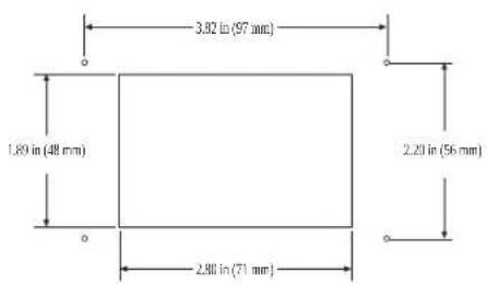
E/5 Pasir' n1a) o Dutillio ) onta0i) as
E/6 E1rano s1y('lio) onta0i) as
O. Drijun ite e rano abelio [ onta to jungo prie virCutinio deCiniojo lizdo monta) inaje plo Staje.
1. /it" e rano abelio gal" prijun ite prie e rano lizdo e rano s ydelio galinäje pusäje.
Π
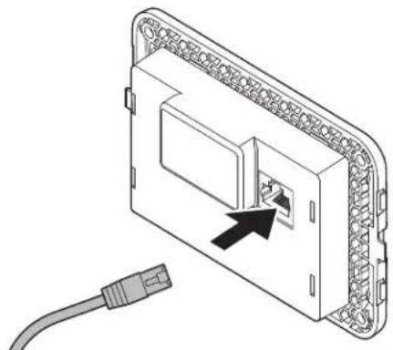
natural_image
Diagram of an electronic device showing a connector with an attached cable (no text or symbols present)U. ' audodami eturis var) tus pritvirtin ite e rano s ydel prie pertvaros. N' nau( o1it' var) tõ pistoleto ir nepriver) ite var) tõ per stipriai.
K. . ) spaus ite apvad" ant e rano s ydelio rāmo.
□
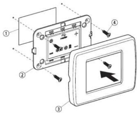
| Pa( / Aprašy) as | |
| 1 ‘ nga | |
| 2 S rano s ydelis | |
| 3 ‘ pvadas | |
| 4 ‘ ar) tas |
E/5 E1rano ti1rini) as
AUTOA ATINIS r'ži) as
* tlie amas Gildymas ir väsinimas? ižrint o rei ia mustatytai temperatžrai abinoje pasie ti.
Q. Sistema pradeda văsinimo ci 1 ^P ai temperatžra abinoje virčija nustatyt“j” | ip| fôlpc i ir pradeda Gildymo ci 1 ^P ai temperatžra abinoje tampa | p] fôlpc i emesnă u) nustatyt“j”. Sistema tęsia ci 1 ^P ol temperatžra abinoje tampa lygi nustatytajai.
I. ci lo metu temperatžra abinoje turi tampa) emesnă u) nustatyt"j" bent Klp] fl lpc IP ad sistema persijungtõ i3 väsinimo i Gildym"p arba virčyti nustatyt"j" bent Klp] fl lcc IP ad sistema persijungtõ i3 Gildymo i väsinim". No ia vei sena neleid) ia mai) iems temperatžroms svyravimams perjunginăti sistemos tarp Gildymo ir väsinimo? ai tai nebžtina.
Vésini) o r'ži) as
Juo atlie amas ti väsinimas ^3 o „I|L eMO re) imu atlie amas ti Gildymas.
F/2 Val(y) o op' racidos pasirin1i) as
- Nap the Mode icon to select a mode.
Refer tov* vailable Modes and Options for Operation#.
- L isplay icons illuminate to indicate the selected mode.
Nhe display loc s into the last mode selected arrer Wve seconds of inactivity ^9 then displays the room temperature. Nhe selected mode |SL remains lit.
* mer 0J seconds of inactivityF the display shows the room temperature and enters the IL1S state.
O]] displays on the screen to indicate the O]] state.
Y hen the display is ma ing a call for heating ^p cooling ^p auT heat ^p or humidity ^p the appropriate Mode indicator blin s for two seconds O' and two seconds O] ].
- Nap any icon to wave up the control from the O] or IL |S state.
U. Nap and hold the Mode icon for three seconds to start a SI SSD state.
√ Nhe display goes dar .
ormal operation continues.
K. Nap and hold the Mode icon for three more seconds to wave up the control.
F/5 Val( i1lio '1rano s1y('lio nau( oDi) as
Noliau patei toje lentelaje patei iami pi togramö deriniai ^p uriuos rei ia naudoti norint sua tyvinti s irtingas valdi lio lun cijas.
| Piltogra) u ( 'rinys Piltogra) u pa0a( ini) ai ir ,un1ciños | |
| MODE 4 | Mode ir Up" tidaryti programavimo menius0. ' ienu metu palies ite ir palai y ite tris se undes ^2 ai valdi lis vei ia I.,J. ' MIMO re} imu.S rane rodoma DC. |
LT0000
Pil togra) u ('rinys Pil togra) u pa0a( ini) ai ir ,un1 cilos
| 4 = | Up ir DownRodyti lau o temperatžr”a0. ’ ienu metu palies ite ir palai y ite tris se undes./ol lai ote paspaude 6i pi togramó derin’ e rane paeiliui rodoma O. ir lai o temperatžros rodmuo. |
| 4 + | Fan ir UpRodyti jzros vandens temperatzr”a0. ’ ienu metu palies ite ir palai y ite tris se undes./ol lai ote paspaude 6i pi togramó derin’ e rane paeiliui rodoma SS ir jzros vandens temperatžros rodmuo. |
| 4 4 MODE | Up3 Down ir ModeRodyti santy in: drăgnia0. ’ ienu metu palies ite ir palai y ite tris se undes./ol lai ote paspaude 6i pi togramó derin’ e rane paeiliui rodoma k S ir santy inio drăgnio rodmuo. |
| MODE 4 = | Mode ir Down” tidaryti tri čio istorij”a0. ’ ienu metu palies ite ir palai y ite tris se undes? ai valdi lis vei ia I,J. ’ MIMO re) imu? atsidarys tri čio istorijos ) urnalas.S rane ičsaugoma i i ačtuonið tri čio.I . . se the Up and Down icons to view theault history.U. ’ ienu metu palies ite ir tris se undes palai y ite pi - togramas Mode ir Downl jei norite ičvalyti tri čio is- torij”.K. Ičei ite vien“ art” paliesdami pi togram“ Mode. |
| 4 = | Fan ir DownNi L ga rodyti ompresoriaus vei imo lai o valandõ s ai- ti la0. ’ ienu metu palies ite ir palai y ite tris se undes? ai valdi lis vei ia I,J. ’ MIMO re) imu.S rane vien“ art” parodomas odas kr’ tada rodo- mas vei imo lai as.I , Išei ite vien“ art” paliesdami pi togram“ Mode. |
F/6 Val(i1lio progra) a0i) as

PASTA A Jei jžsô oro ondicionieriuje naudojamas ventiliatoriaus vari lis su e ranuotais poliais fSDF o ne didelio greičio fk 't ventilatoriaus vari lis su darbiniu ondensatoriumi fScF prič' naudodarni prietais' u) programuo ite SD ventilatoriaus vari lio tipo parametre. Žr: „ aldi lio programavimasv. SD prietaisus galima atpa) inti i0 i0si i0cusio pžstuvo vari lio. k' prietaiso Sc varii lis yra pžstuvo viduje" be tof modelio numeryje naudojamos raidas 'NL arba k'. Derprogramuo ite ventiliatoriaus tipo parametr' ti jei neturite k' pžstuvo.
F/6/1 Progra) a0i) o r'ži) o ati(ary) as
| +ir Sensor Fault |
| High Pressure Fault |
| Low Pressure Fault |
| Low + C Fault |
| Pump Sentr' Fault |
FAULT CODES
| S6-- inside Sensor Failure |
| r6FL Clean6Replace Filter |
| LO6+C Low +C Voltage |
| S+H High Suppl(+ir Temp |
| LO6S1 Sea . ater Low Limit |
| SLP Sleep 3 ode |
| HPF High Pressure Fault |
| LPF Low Pressure Fault |
| PLF Pump Sentr(Fault |
| L6-- Loop-. ater Sensor |
DX PROGRAMMABLE PARAMETERS
P- High Fan Limit
P-2 Low Fan Limit
P-7 Compressor Staging Time Dela
P-/ inside +ir Temperature Sensor Calibration
P-5 Failsale Le-el
P-& Low Voltage 3 onitor
P-9 De-)cing C(cle
P-8 Optional Pump Sentri(
P-9 Displa( Brightness Control
P- 0 Fahrenheit or Celsius Selection
P- C(cle Pump with Compressor
P- 2 Re- erse +utomatic Fan Speeds During Heating
P-7 Cool-Onl(3ode
P- / Fan 3 otor Selection
P- 5 Restore Factor( Default Settings
P- & Reser-ed
P-9 Reser-ed
P- 8 +ir Filter Cleaning6Replacement Timer Setting
P-9 Filter Cleaning6Replacement Timer Value 4 Reset
P-20 C+N Bus Unit |D
P-2 C+N Bus Group |D
P-22 Voltage Calibration
P-27 Set Point Temperature Differential
P-2/ Dehumidi5cation 3 ode 3 inimum Temperature
P-25 +uto Fan Speed Temperature Differential
P-2& Suppl(-ir High Temperature Limit
P-29)dle State Dela(
P-28 +uOiliar( Heat 1nable
P-29 Relati-e Humidit( 1nable
P-70 Seawater Low-Limit +djustment
P-7 Humidit(Sensor Calibration
P-72 .ater Inlet Temperature Sensor Calibration
P-77 O+T Sensor Calibration
CW PROGRAMMABLE PARAMETERS
P- High Fan Limit
P-2 Low Fan Limit
P-7 Reser-ed
P-/ inside +ir Temperature Sensor Calibration
P-5 Reser ed
P-& Low Voltage 3 onitor
P-9 Reser-ed
P-8 Reser-ed
P-9 Displa( Brightness Control
P- 0 Fahrenheit or Celsius Selection
P- Reser-ed
P-2 Re-erse+utomatic Fan Speeds During Heating
P-7 Reser-ed
P- / Fan 3 otor Selection
P- 5 Restore Factor, Default Settings
P- & H(dronic. later Val-e Forced Open
P-9. later Temperature Differential
P- 8 +ir Filter Cleaning&Replacement Timer Setting
P-9 Filter Cleaning6Replacement Timer Value 4 Reset
P-20 C+N Bus Unit D
P-2 C+N Bus Group |D
P-22 Voltage Calibration
P-27 Set Point Temperature Differential
P-2/ Dehumidi5cation 3 ode 3 inimum Temperature
P-25 +uto Fan Speed Temperature Differential
P-2& Suppl(+ir High Temperature Limit
P-29 |dle State Dela(
P-28 +uOiliar( Heat 1nable
P-29 Relati-e Humidit( 1nable
P-70 Reser-ed
P-7 Humidit(Sensor Calibration
P-72. ater Inlet Temperature Sensor Calibration
P-77 O+T Sensor Calibration
DOMETIC AUSTRALIA PTY LTD
1 JOHN DUNCAN COURT
VARSITY LAKES, QLD, 4227
1800-212-121
DOMETIC NEW ZEALAND LTD
373 NEILSON STREET
PENROSE, AUCKLAND, 1061
+64 9 622 1490
In,or) acida ti1 Australidai
E U4stā(īšana
„ajE sada:E ir apra st'ta piemúrota atraGanEs vieta? atraGanEs vietas sagatavočana un capNouch vad-bas ierfces uzstEdGana.

natural_image
Diagram of an electronic device showing a connector with an arrow pointing to a port, connected to a cable (no text or symbols present)U. Izmantojiet četras s ržvesf as paredzutas displeja panesa piestiprinEganai pie starpsienas, N' li' toli' t ele tris o s ržvgriezi un nepievelciet s ržves pErE cieši,
K. . zlieciet ietvaru uz displeja paneja rEmja.
□

| Po4/Apralsts | |
| 1 Izgriezums | |
| 2 L ispleja panelis | |
| 3 letvars | |
| 4 S ržves |
Q. Nap the Mode icon to select a mode.
Refer tov* vailable Modes and Options for Operations.
√ L isplay icons illuminate to indicate the selected mode.
Nhe display loc s into the last mode selected arrer Wve seconds of inactivity? then displays the room temperature. Nhe selected mode |SL remains lit.
* mer 0j seconds of inactivityf the display shows the room temperature and enters the IL1S state.
O] displays on the screen to indicate the O] state.
Y hen the display is ma ing a call for heating ^p cooling ^p auT heat ^p or humidity ^p the appropriate Mode indicator blin s for two seconds O' and two seconds O] ].
- Nap any icon to wave up the control from the O] or IL |S state.
U. Nap and hold the Mode icon for three seconds to start a SI SSD state.
√ Nhe display goes dar .
'ormal operation continues.
K. Nap and hold the Mode icon for three more seconds to wave up the control.
C( cled6Continuous Fan 3 ode
FAULT HELP
+ir Sensor Fault
High Pressure Fault
Low Pressure Fault
Low + C Fault
Pump Sentr' Fault
FAULT CODES
)S6- - )inside Sensor Failure
r6FL Clean6Replace Filter
LO6+C Low+C Voltage
S+H High Suppl(+ir Temp
LO651 Sea. later Low Limit
SLP Sleep 3 ode
HPF High Pressure Fault
LPF Low Pressure Fault
PLF Pump Sentr( Fault
)L6--Loop-.ater Sensor
DX PROGRAMMABLE PARAMETERS
P- High Fan Limit
P-2 Low Fan Limit
P-7 Compressor Staging Time Dela
P-/ inside +ir Temperature Sensor Calibration
P-5 Failsale Le-el
P-& Low Voltage 3 onitor
P-9 De-)cing C(cle
P-8 Optional Pump Sentri(
P-9 Displa( Brightness Control
P- 0 Fahrenheit or Celsius Selection
P- C(cle Pump with Compressor
P- 2 Re- erse +utomatic Fan Speeds During Heating
P-7 Cool-Onl(3ode
P- / Fan 3 otor Selection
P- 5 Restore Factor( Default Settings
P- & Reser-ed
P-9 Reser-ed
P- 8 +ir Filter Cleaning6Replacement Timer Setting
P-9 Filter Cleaning6Replacement Timer Value 4 Reset
P-20 C+N Bus Unit |D
P-2 C+N Bus Group |D
P-22 Voltage Calibration
P-27 Set Point Temperature Differential
P-2/ Dehumidi5cation 3 ode 3 inimum Temperature
P-25 +uto Fan Speed Temperature Differential
P-2& Suppl(-ir High Temperature Limit
P-29)dle State Dela(
P-28 +uOiliar( Heat 1nable
P-29 Relati-e Humidit( 1nable
P-70 Seawater Low-Limit +djustment
P-7 Humidit(Sensor Calibration
P-72 .ater Inlet Temperature Sensor Calibration
P-77 O+T Sensor Calibration
CW PROGRAMMABLE PARAMETERS
P- High Fan Limit
P-2 Low Fan Limit
P-7 Reser-ed
P-/ inside +ir Temperature Sensor Calibration
P-5 Reser ed
P-& Low Voltage 3 onitor
P-9 Reser-ed
P-8 Reser-ed
P-9 Displa( Brightness Control
P- 0 Fahrenheit or Celsius Selection
P- Reser-ed
P-2 Re-erse -utomatic Fan Speeds DuringHeating
P-7 Reser-ed
P- / Fan 3 otor Selection
P- 5 Restore Factor, Default Settings
P- & H(dronic. later Val-e Forced Open
P-9. later Temperature Differential
P- 8 +ir Filter Cleaning&Replacement Timer Setting
P- 9 Filter Cleaning6Replacement Timer Value 4 Reset
P-20 C+N Bus Unit D
P-2 C+N Bus Group |D
P-22 Voltage Calibration
P-27 Set Point Temperature Differential
P-2/ Dehumidi5cation 3 ode 3 inimum Temperature
P-25 +uto Fan Speed Temperature Differential
P-2& Suppl+ir High Temperature Limit
P-29 |dle State Dela(
P-28 +uOiliar( Heat 1nable
P-29 Relati-e Humidit( 1nable
P-70 Reser-ed
P-7 Humidit(Sensor Calibration
P-72. ater Inlet Temperature Sensor Calibration
P-77 O+T Sensor Calibration
DOMETIC AUSTRALIA PTY LTD
1 JOHN DUNCAN COURT
VARSITY LAKES, QLD, 4227
1800-212-121
DOMETIC NEW ZEALAND LTD
373 NEILSON STREET
PENROSE, AUCKLAND, 1061
+64 9 622 1490
Tilai Australiā
Mžsu precúm ir garantija uru nedr st izslúgt sas a E ar "ustrElijas patúrútEju tiesíbu normEm. Jums ir ties-bas uz nomai u vai naudas atgriečanu par bztis iem dele tiem un
uz ompensEciju par citiem pamatoti paredzamiem zaudújumiem vai bojEjumiem. Jums ir ar' ties'bas pieprasít preču remontu vai nomai u'ja preču valitEte ir nepie emamaf bet de'e ti nav uzs atEmi par bžtis iem de'e tiem.
Ti1ai raun4elan(ē
. z Go garantiju attiecinEmi notei umi un garantijas ^2 as notei tas E obligEtas Q99U, gada DatúrútEju garantiju li umE f' Zh.
Vi' tēDais atbalsts
I ai uzzinEtu par vietújE atbalsta iespújEm² apme lújiet tEIE norEd'to saitia dometic.com/dealer
dometic.com/sales-offices