ACC3100D - Fan DOMETIC - Free user manual and instructions
Find the device manual for free ACC3100D DOMETIC in PDF.

| Product type | Roof ventilation system with heat recovery |
| Brand | Dometic |
| Model | ACC3100D |
| Input voltage | 12 V= |
| Maximum power | 7.6 W (ACC3100DWHA) / 16.5 W (ACC3100DWHWLDA) |
| Maximum power consumption | 0.18 kWh/24h (ACC3100DWHA) / 0.40 kWh/24h (ACC3100DWHWLDA) |
| Airflow rate | 30 to 50 m³/h |
| Heat recovery efficiency | 72 to 87 % |
| Weight | 7 kg (ACC3100DWHA) / 7.14 kg (ACC3100DWHWLDA) |
| Indoor air filter | Ref. 9620015799 |
| Outdoor air filter | Ref. 9620015800 |
| Optional accessories | LED lighting strip, Air purification module, Performance optimization module, Solar panel |
| Intended use | Caravans, motorhomes, pleasure boats |
| Installation | By a certified technician |
| Maintenance | Regular cleaning of filters; replace filters if necessary |
| Warranty | Refer to the manual for conditions |
Frequently Asked Questions - ACC3100D DOMETIC
User questions about ACC3100D DOMETIC
0 question about this device. Answer the ones you know or ask your own.
Ask a new question about this device
Download the instructions for your Fan in PDF format for free! Find your manual ACC3100D - DOMETIC and take your electronic device back in hand. On this page are published all the documents necessary for the use of your device. ACC3100D by DOMETIC.
USER MANUAL ACC3100D DOMETIC
→ DOMETIC CLIMATE CONTROL ROOF TOP VENTILATION SYSTEM
natural_image
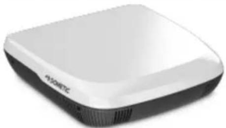
White and black electronic device with no visible text or symbols on its bodyACC3100D

Ventilation system
Installato on Manual 3

Liftungsanlage
f Mortgage and Inung 22

Vetraci system
© 2024 Dometic Group. The visual appearance of the contents of this manual is protected by copyright and design law. The underlying technical design and the products contained herein may be protected by design, patent or pending patent. The trademarks mentioned in this manual belong to Dometic Sweden AB. All rights are reserved.
English
1 Important notes....3
2 Explanation of symbols.... 3
3 Safety instructions....3
4 Scope of delivery....5
5 Accessories....5
6 Target group....6
7 Intended use....6
8 Installation....6
9 Disposal....20
10 Warranty....20
11 Technical data....20
1 Important notes
Please read these instructions carefully and follow all instructions, guidelines, and warnings included in this product manual in order to ensure that you install, use, and maintain the product properly at all times. These instructions MUST stay with this product.
By using the product, you hereby confirm that you have read all instructions, guidelines, and warnings carefully and that you understand and agree to abide by the terms and conditions as set forth herein. You agree to use this product only for the intended purpose and application and in accordance with the instructions, guidelines, and warnings as set forth in this product manual as well as in accordance with all applicable laws and regulations. A failure to read and follow the instructions and warnings set forth herein may result in an injury to yourself and others, damage to your product or damage to other property in the vicinity. This product manual, including the instructions, guidelines, and warnings, and related documentation, may be subject to changes and updates. For up-to-date product information, please visit epdvn foutjepn fujddpn .
2 Explanation of symbols
A signal word will identify safety messages and property damage messages, and also will indicate the degree or level of hazard seriousness.

WARNING!
Indicates a hazardous situation that, if not avoided, could result in death or serious injury.

CAUTION!
Indicates a hazardous situation that, if not avoided, could result in minor or moderate injury.

NOTICE!
Indicates a situation that, if not avoided, can result in property damage.

NOTE Supplementary information for operating the product.
3 Safety instructions

WARNING! Failure to obey these warnings could result in death or serious injury.
Repair of the appliance may only be carried out by qualified personnel who are familiar with the risks involved and the relevant regulations. Inadequate repairs may cause serious hazards. For repair service, contact the service center in your country (see epn fujd;dpn -ef bnf s).
EN
The appliance shall be installed in accordance with national electrical and mechanical installation regulations.
Electrical appliances are not toys. Keep electrical appliances out of reach of children or infirm persons. Do not allow them to use electrical appliances without supervision.
Persons whose physical, sensory or mental capabilities or whose lack of experience and knowledge prevent them from using the appliance safely should not use it without supervision or instruction by a responsible person.
Do not undo the upper cover of the appliance in the event of a fire. Use approved extinguishing agents instead. Do not use water to extinguish fires.
The appliance shall be stored in a room without continuously operating open flames (for example an operating gas appliance) and ignition sources (for example an operating electric heater).
The appliance shall be stored horizontally at a dry, ventilated and covered location.
Do not pierce or burn the appliance.

CAUTION! Failure to obey these cautions could result in minor or moderate injury.
Only start up the appliance if you are certain that the housing and the cables are not damaged.
Do not use the appliance near flammable fluids or in closed rooms.
Ensure that no combustible objects are stored or installed near the air outlet. A distance of at least 10 cm must be kept.
Do not reach into air outlets or insert any foreign objects in the appliance.
Always wear protective goggles and gloves.

NOTICE! Damage hazard
The appliance shall be stored so as to prevent mechanical damage from occurring.
Before installation, check whether any vehicle components could be damaged by the installation of the appliance (such as lamps, cupboards, doors). The vehicle manufacturer may have already provided points where the opening for the installation of the appliance can be made without any risk of weakening the construction or cutting power cables.
Before installation, consult the vehicle manufacturer whether the construction is designed for the static weight and the loads of the ventilation system when the vehicle is in motion.
Seal all openings made when installing the ventilation system.
Select a flat and sufficiently level area at the center of the vehicle roof between two longitudinal sections for installation.
Ensure that there are no objects within the vehicle which could obstruct the attachment of the air distribution box (ADB) or the fresh air from flowing through the air outlets.
Do not make any alterations or conversions to the appliance.
Never drive through automatic car washes when the appliance is mounted.
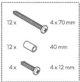
4 Scope of delivery
1
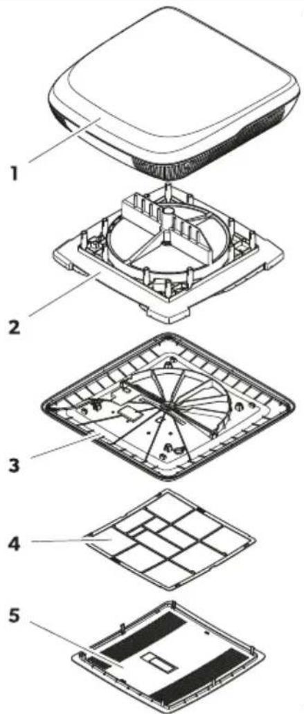


Item Quantity Description
| 11 Roof top unit with center ring (only for roof openings 400 × 400 mm) |
| 21 Heat exchanger unit |
| 31 Interior cover |
| 41 Air filter |
| 51 Center cover |
| -1 Installation kit (to be ordered seperatly for ACC3100DWHA) |
| -1 Short operating manual |
| -- Depending on the model: Installation manuals for accessories |
5 Accessories
| Product Ref. no. | |
| Air purifier 9620005077 | |
| LED light 9620005081 | |
| Performance booster 9600050054 | |
| Solar kit 9620005074 | |
| Inside air filter 9620015799 | |
| Outside air filter 9620015800 |
6 Target group

The mechanical and electrical installation and setup of the device must be performed by a qualified technician who has demonstrated skill and knowledge related to the construction and operation of automotive and household equipment and installations, and who is familiar with the applicable regulations of the country in which the equipment is to be installed and/or used, and has received safety training to identify and avoid the hazards involved.
7 Intended use
The ventilation system is intended to be installed in motor homes, caravans and leisure boats.
The ventilation system is not suitable for:
- Houses
- Apartments
- Cruiseline
- Construction machines
• Agricultural machines - Trucks
This product is only suitable for the intended purpose and application in accordance with these instructions.
This manual provides information that is necessary for proper installation and/or operation of the product. Poor installation and/or improper operation or maintenance will result in unsatisfactory performance and a possible failure.
The manufacturer accepts no liability for any injury or damage to the product resulting from:
- Incorrect installation, assembly or connection, including excess voltage
- Incorrect maintenance or use of spare parts other than original spare parts provided by the manufacturer
• Alterations to the product without express permission from the manufacturer - Use for purposes other than those described in this manual
Dometic reserves the right to change product appearance and product specifications.
8 Installation

WARNING! Electrocution hazard
The electrical power supply must be connected by a qualified electrician who has demonstrated skill and knowledge related to the construction and operation of electrical equipment and installations and has received safety training to identify and avoid the hazards involved.
Disconnect all power supplies when working on the ventilation system.
Ensure that the appliance cannot be reconnected.

WARNING! Electrocution hazard
The appliance shall be installed in accordance with national wiring regulations.
If the appliance replaces a window or hatch with a safety relevant forced venting function, an additional safety venting device (e.g. a mushroom fan or similar) needs to be added. In doubt consult the vehicle manufacturer.

CAUTION! Risk of injury
Improper installation of the ventilation system can result in irreparable damage to the appliance and put the safety of the user at risk.
Always have someone to help you carrying or lifting the ventilation system.
Before installation, check the location of existing wiring harnesses, wires and other components within the installation area, in particular those which are not visible, when installing the appliance (when drilling or screwing etc.).
Attach and lay the cables so that they cannot be tripped over or damaged.
Always wear the protective goggles and gloves.

NOTICE! Damage hazard
Use cable ducts to lay cables through walls with sharp edges.
Do not lay loose or bent cables next to electrically conductive materials (metal).
Do not pull on the cables.
Observe the structural strength of the roof of the vehicle. The roof of the vehicle must be able to bear the weight of the ventilation system without being indented or deformed. In doubt consult the vehicle manufacturer.
Choosing the way of installing the ventilation system

NOTE
- Choose a flat and sufficiently level area at the center of the vehicle.
- The roof inclination of the installation surface may not exceed 5^ . A downwards inclination in the driving direction of up to 15^ is possible.
Choose your way of installing the ventilation system:
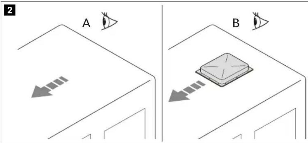
- Make a new opening (A). In this case the opening must be reinforced by an appropriate frame.
- Use an existing opening in the vehicle (B) such as a roof hatch or replacing an old device.
EN
Making a new opening
- Select an area at the center on the roof between two longitudinal supports.
- Mark the position and size of the opening.
3
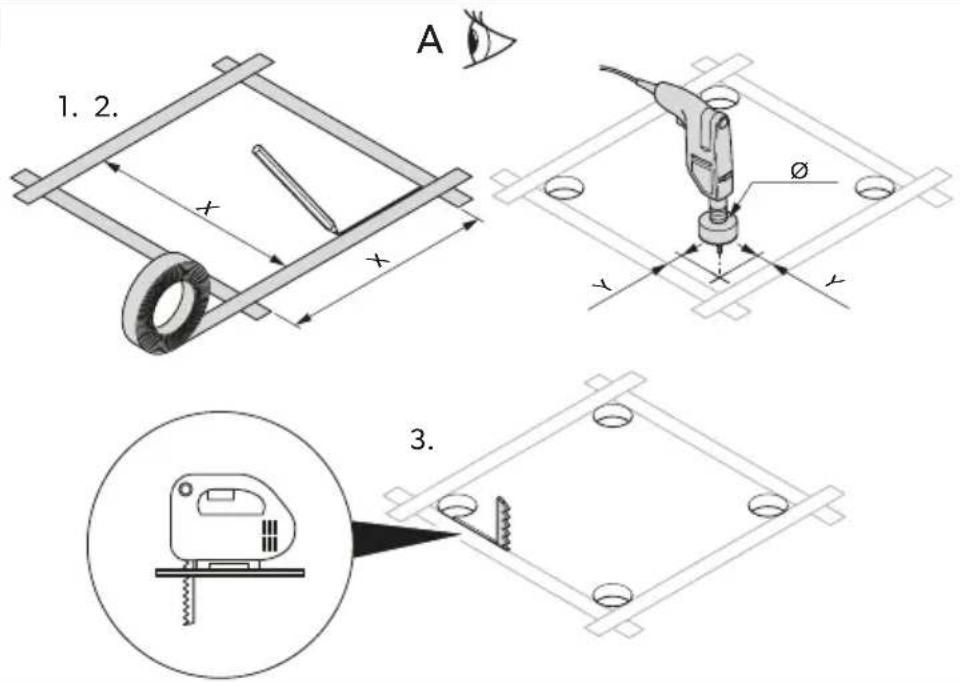
| Version 1 Version 2 | |
| X 355 mm 400 mm | |
| Y 5 mm 12 mm | |
| ∅ 10 mm 24 mm |
- Drill out the corners.

NOTICE! Damage hazard
Ensure that no electrical power cables are damaged. Check where the electrical cables are located.
- Carefully cut out the opening on the roof using a keyhole saw or a similar tool.
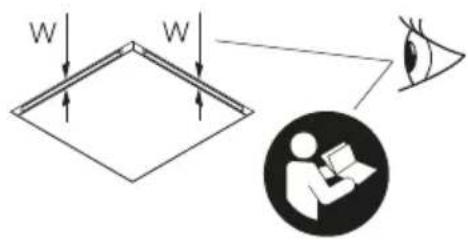
- Check whether the roof hole needs reinforcing.

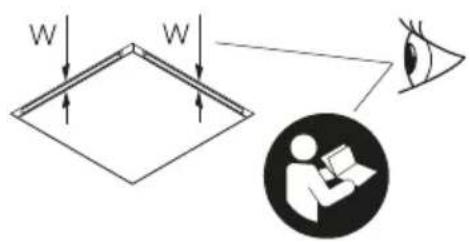
NOTE The edges must be parallel to each other.
4
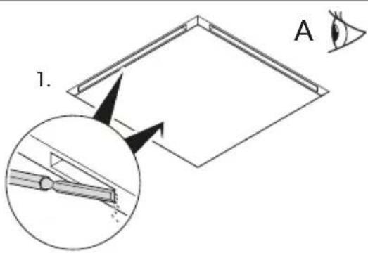
- If needed, remove the foam according to the width of your reinforcing rails (not in scope of delivery).
- Fit the reinforcing rails.
Installing in an existing opening
- Remove all screws and fixtures of the existing roof hatch or device.
5
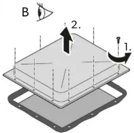
natural_image
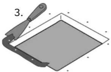
Illustration of a trowel and a square object with a handle, no text or symbols present- Take out the roof hatch or device.
- Remove the sealant around the opening using a scraper or similar tool.
Installing optional accessories (depending on the model)

NOTICE! Damage hazard
Observe the correct installation sequence before making the electrical connections.
Observe the installation manuals of the accessories (optional).
- Roof top unit
- Solar panel (optional)
- LED light strip (optional)
- Air purification module (optional)
- Heat exchanger unit
- Performance booster (optional)
- Interior cover
EN
Laying the connecting cables
- Check that the voltage specification on the data plate of the ventilation system is the same as that of the power supply. The ventilation system must be connected to an electric circuit which is able to supply the required current.
- Install an all-pole switch with a contact opening width of at least 3 mm on the installation side.
- Select the cross-section of the power supply cable corresponding to the length:
• Length < 7.5 m: 1.5 mm ^4
- Length > 7.5 m : 2.5 mm^2
- Make an opening on one side in order to feed through the power supply cable.
6
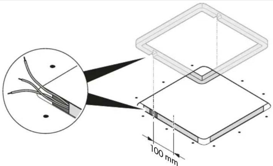
- Feed the power supply cable through the opening into the vehicle interior.
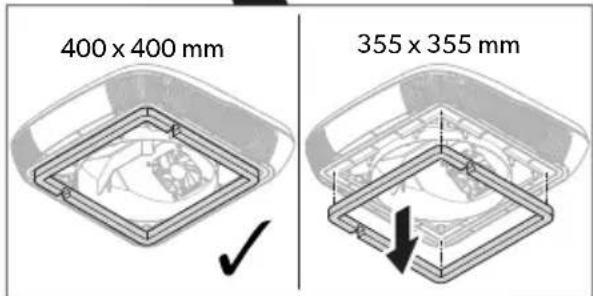
Installing the roof top unit
- Only for version 1: Remove the center ring on the roof top unit.
7
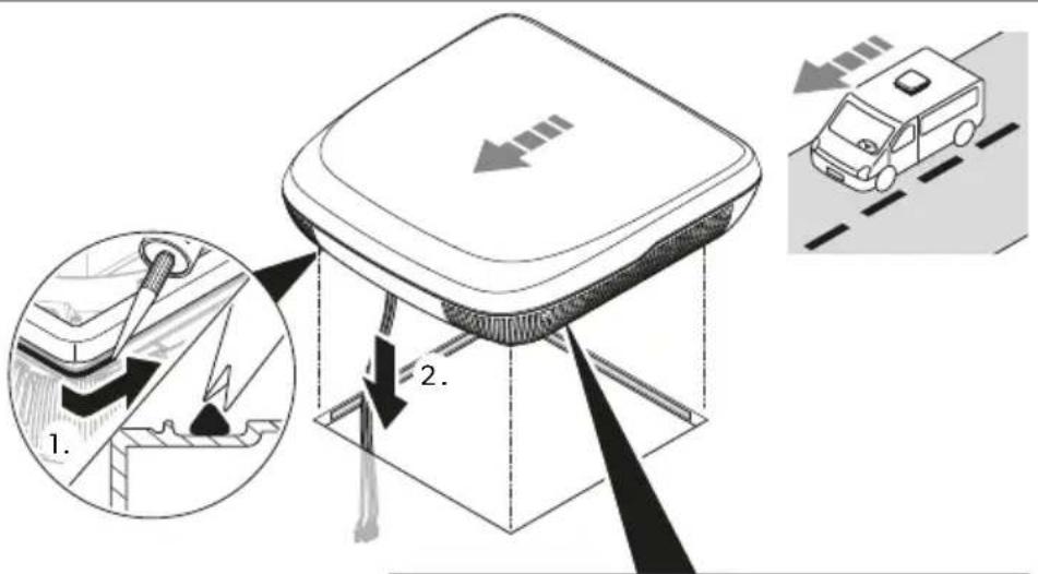

- Seal around the roof frame with flexible non-hardening butyl sealing compound (e.g. SikaLastomer-710, Selleys Butyl Mastic, Bostik ezycaulk butyl sealant, or similar products). Observe the sealant manufacturer's instructions.
- Lift the roof top unit onto the roof of the vehicle. Observe the direction of travel.
- Position the roof top unit centrally on the roof of the vehicle.
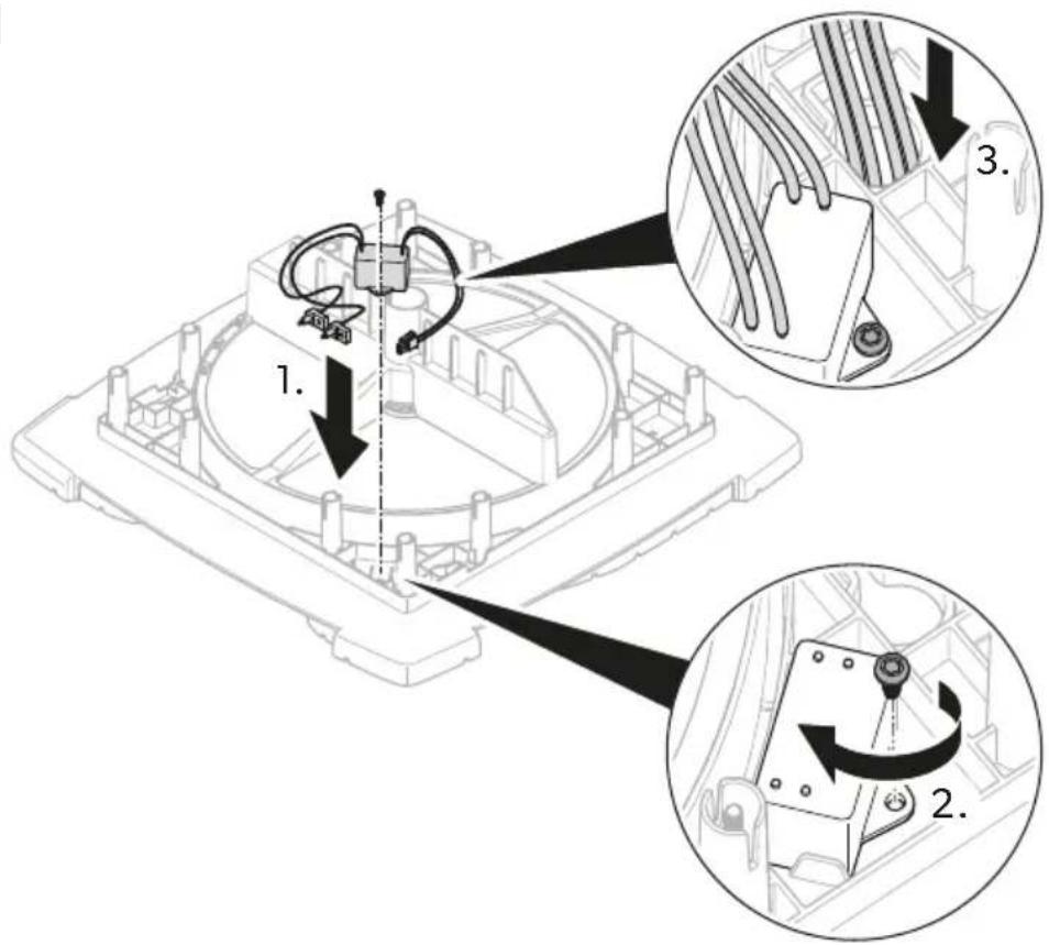
- Remove the cable tie on the rooftop unit and lead the cables through the corresponding opening into interior of the vehicle.
Installing the air purification module (optional)
- Fix the air purification module to the heat exchanger unit.
EN
8

- Lead the cable through the key hole bushing to the underside of the heat exchanger unit.
- Mount the ionization needle.
9

Installing the heat exchanger unit
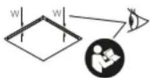
- Depending on the roof thickness, cut the spacers supplied with the fixing kit to the required lenght.
10
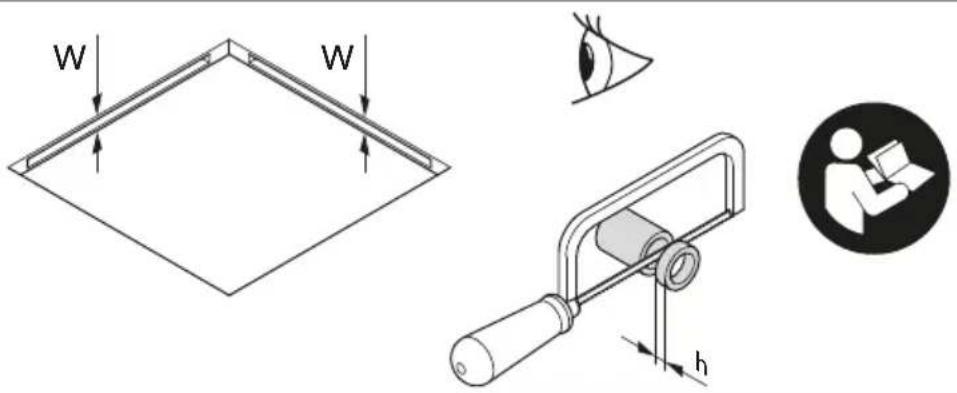
| Roof thickness (W) Spacer length required (h) | |
| 23 mm - | |
| 24 mm | 2 mm |
| 25 mm | |
| 26 mm | 4 mm |
| 27 mm | |
| 28 mm | 6 mm |
| 29 mm | |
| 30 mm | 8 mm |
| 31 mm | |
| 32 mm | 10 mm |
| 33 mm | |
| 34 mm | 12 mm |
| 35 mm | |
| 36 mm | 14 mm |
| 37 mm | |
| 38 mm | 16 mm |
| 39 mm | |
| 40 mm | 18 mm |
| 41 mm | |
| 42 mm | 20 mm |
| 43 mm | |
| 44 mm | 22 mm |
| 45 mm | |
| 46 mm | 24 mm |
| 47 mm | |
| 48 mm 26 mm |
EN
| Roof thickness (W) Spacer length required (h) | |
| 49 mm | |
| 50 mm | 28 mm |
| 51 mm | |
| 52 mm | 30 mm |
| 53 mm | |
| 54 mm | 32 mm |
| 55 mm | |
| 56 mm | 34 mm |
| 57 mm | |
| 58 mm | 36 mm |
| 59 mm | |
| 60 mm 38 mm |
- Feed the cables through the key hole bushing of the heat exchanger unit.
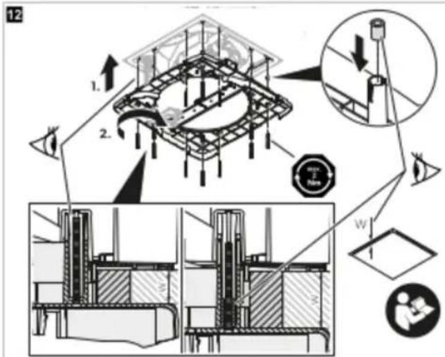
11
- Insert the spacers into the screw holes from the upper side of the heat exchanger unit.
12
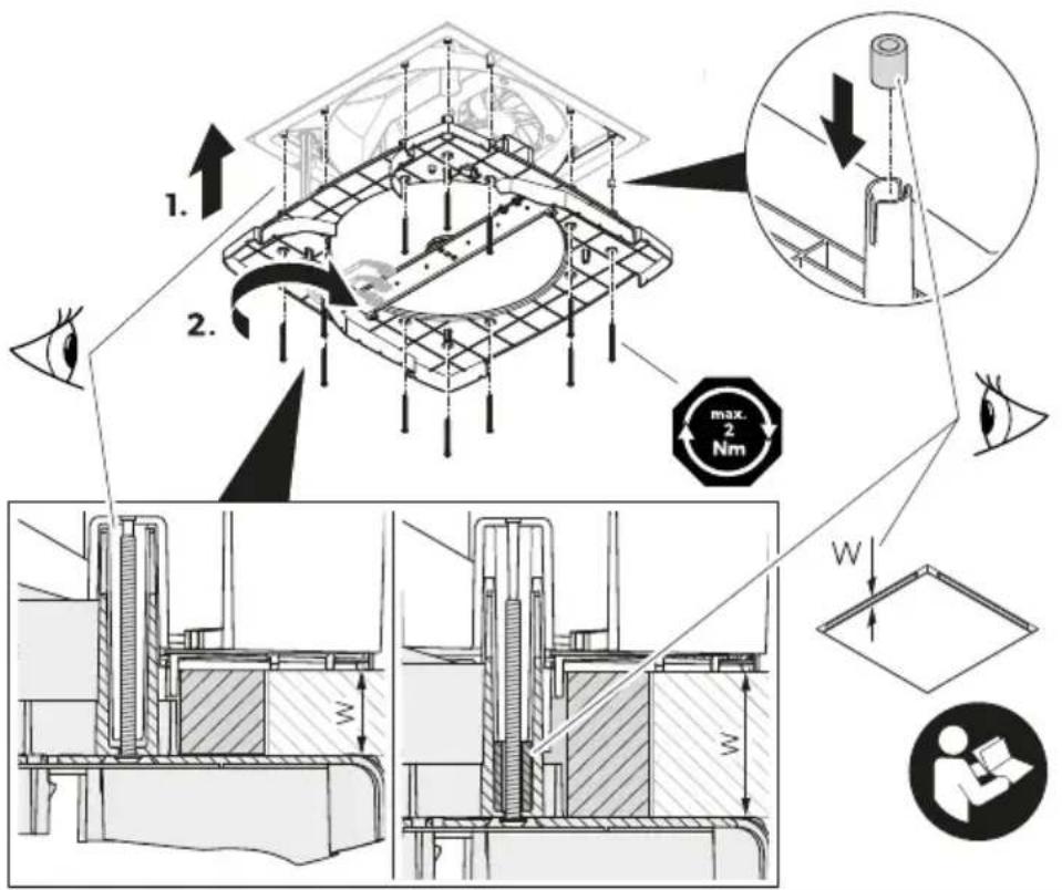
4.

NOTICE! Damage hazard
Ensure that no cable is pressed in or pinched.
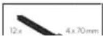
Align the heat exchanger unit to the roof top unit.
- Fasten the heat exchanger unit though the ceiling to the roof top unit with the 12 bolts supplied with the fixing kit. Tighten the bolts using a torque spanner and a fastening torque of max. 1.2 Nm.
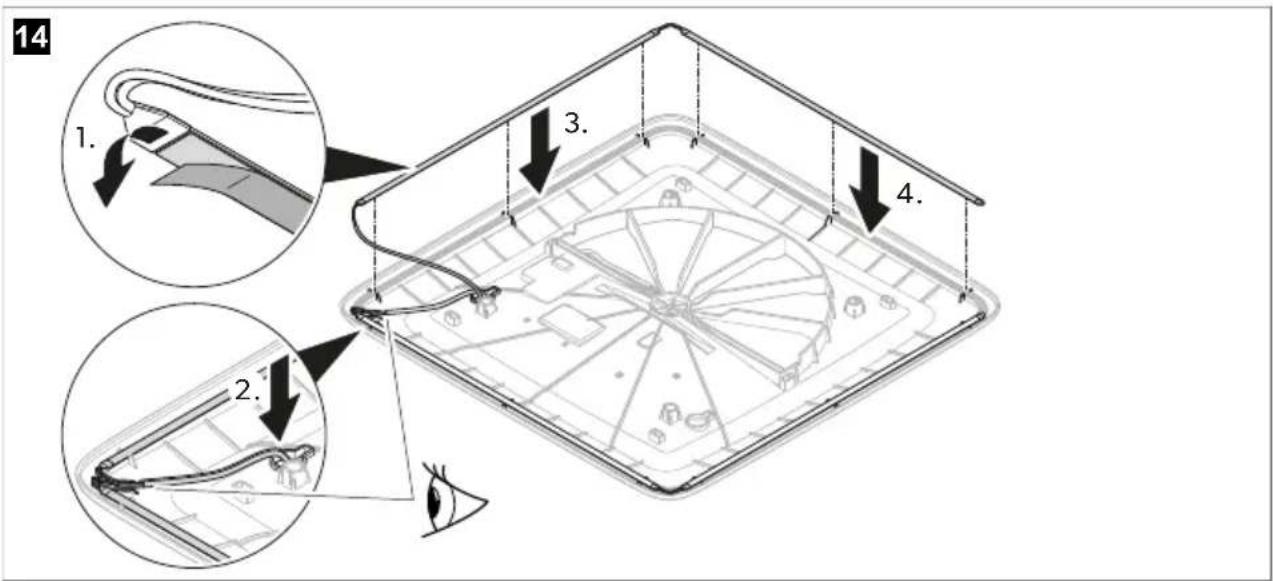
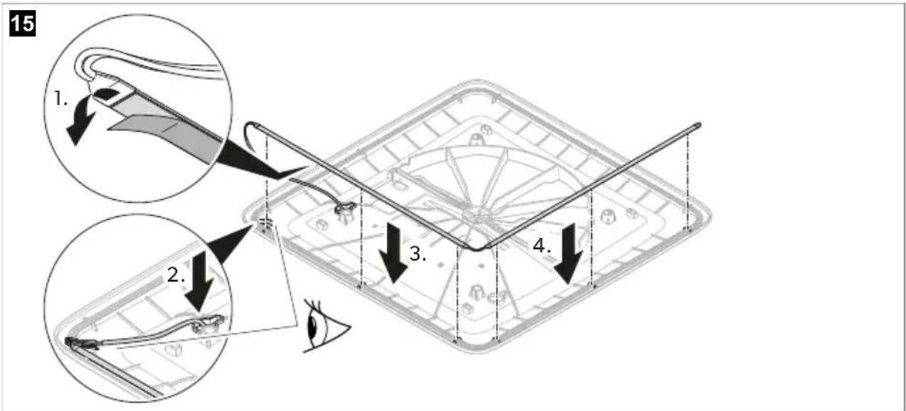
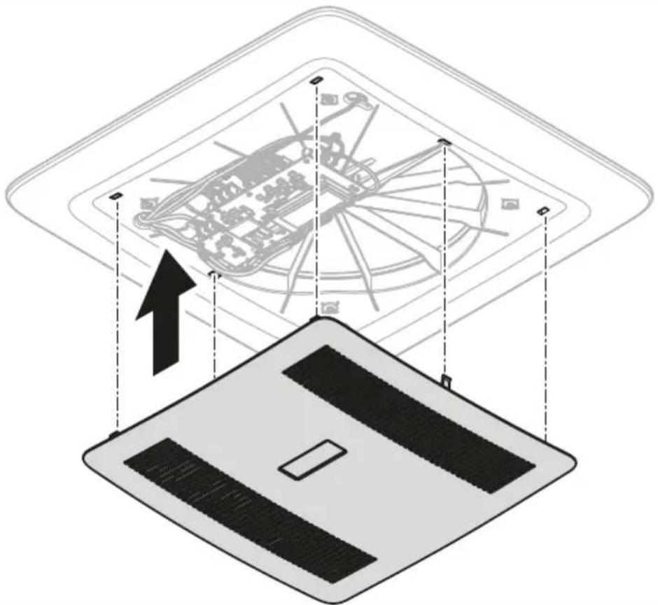
Installing the interior cover
- Feed the cables through the key hole bushing of the interior cover.
13
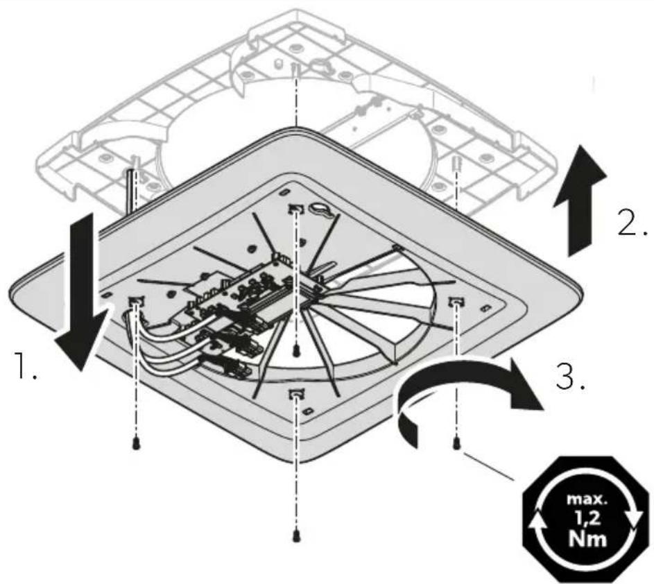
2.

NOTICE! Damage hazard
Ensure that no cable is pressed in or pinched.
Attach the interior cover to the heat exchanger unit.
- Fasten the interior cover to the heat exchanger unit with the 4 bolts supplied with the fixing kit. Tighten the bolts using a torque spanner and a fastening torque of max. 1.2 Nm.
Installing the LED light strip (optional)
Fix the LED light strips to the interior cover.
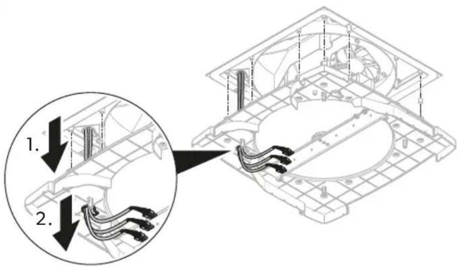
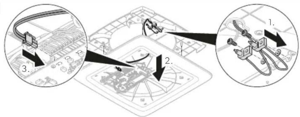
Electrical connection
- Connect the plugs to the sockets.
16
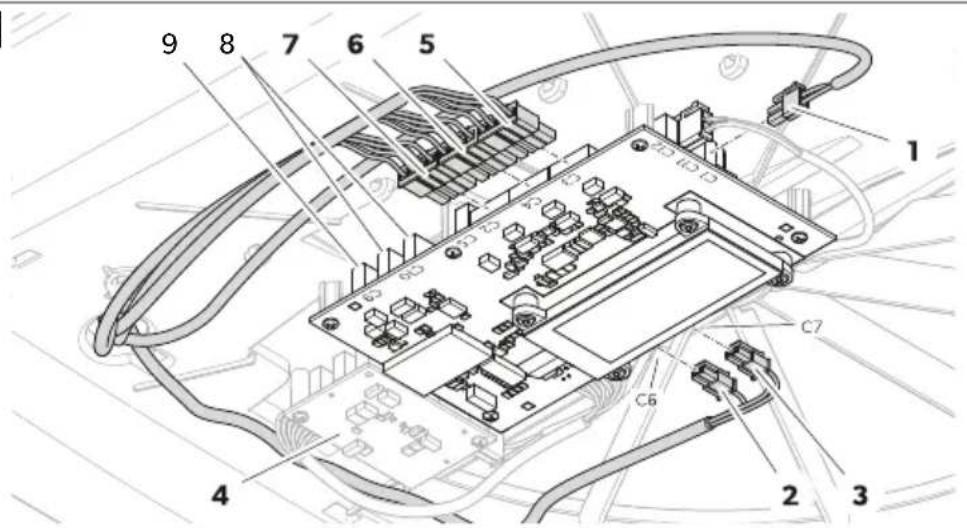
| Item Socket Description | |
| 1 C1 Input power supply from vehicle battery | |
| 2 C6 Output LED light strip (optional) | |
| 3 C7 Output LED light strip (optional) | |
| 4 – Secondary PCB (optional) | |
| 5 C3 Output fan 1 | |
| 6 C4 Output fan 2 | |
| 7 C2 Output motor | |
| – C5 Output air purification module (optional) | |
| 8 C10 Communication CAN (optional) | |
| 9 C9 Communication LIN (optional) | |
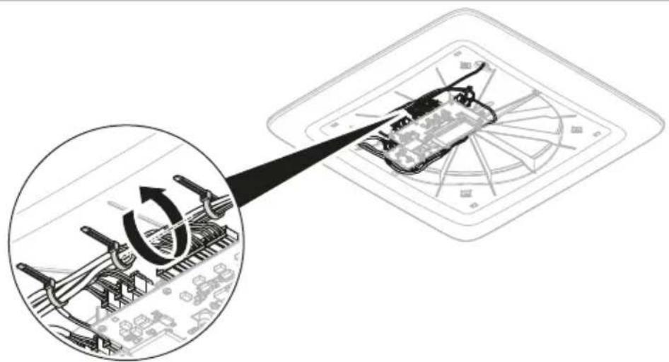
- Secure the cables with cable ties.
17

Installing the ADB center cover
- Check that the filters are fully in.
18
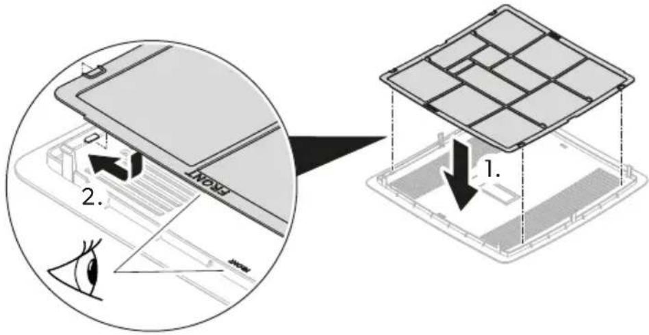
- Clip the ADB center cover to the interior cover.
19

- Ask the vehicle manufacturer if a technical inspection is required after fitting a ventilation system and whether the height entered in the vehicle documents needs to be altered.
√ The installation is now completed.
- Connect to the power supply and test if the ventilation system works.
EN
9 Disposal

Recycling products with batteries, rechargeable batteries, and light sources. Remove any batteries, rechargeable batteries, and light sources before recycling the product. Return defective or used batteries to your retailer or dispose of them at collection points. Do not dispose of any batteries, rechargeable batteries, and light sources with general household waste. If you wish to finally dispose of the product, ask your local recycling center or specialist dealer for details about how to do this in accordance with the applicable disposal regulations. The product can be disposed free of charge.

Recycling packaging material: Place the packaging material in the appropriate recycling waste bins wherever possible.
10 Warranty
For repair and warranty processing, please include the following documents when you send in the device:
• A copy of the receipt with purchasing date
- A reason for the claim or description of the fault
Note that self-repair or nonprofessional repair can have safety consequences and might void the warranty.
11 Technical data
| ACC31000WHA | ACC31000WHWLDA | |
| Input voltage | 12 V/m | |
| Maximum power input | 76 W | 16.5 W |
| Maximum power consumption | 0.18 kWh/24 h | 0.40 kWh/24 h |
| 15.2 Ah/24 h | 33 Ah/24 h | |
| ACC3100DWHA ACC3100DWHWLDA | ||
| Heat recovery efficiency 72 ... 87% | ||
| Weight 7 kg 7.14 kg | ||
| Features | Upgradable with:LED Light StripAir Purification ModulePerformance BoosterSolar Panel | Provided with:LED Light StripAir Purification ModuleInstallation kitUpgradable with:Performance BoosterSolar Panel |
| Certifications |  | |
Deutsch


natural_image
Illustration of a trowel and a square object inside a container, no text or symbols present
4.

8 Installation....44


natural_image
Illustration of a trowel and a flat sheet metal forming a square (no text or symbols)
4.


natural_image
Illustration of a trowel and a square object with a handle, no text or symbols present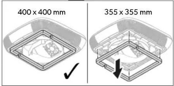
4.


natural_image
Illustration of a trowel and a square object with a handle, no text or symbols present
4.

Instalar a tampa interior
Instalar a tampa central da ADB
- Engate a tampa central da ADB na tampa interior.
19


natural_image
Illustration of a trowel and square object with shading, no text or symbols present
4.


natural_image
Illustration of a trowel and a square object with a handle, no text or symbols present
De warmtewisselaar monteren
4.

v De montage is nu voltooid.


Artikel Antal Beskrivelse
DA

4.

VIGTIGT! Fare for beskadigelse
Kontrollér, at ingen kabler klemmes eller gennemstikkes.


natural_image
Illustration of a plow and a square object with a handle, no text or symbols present
4.

Installera ADB-mittkåpan


Element Antall Beskrivelse
natural_image
Illustration of a trowel and a square object inside a container, no text or symbols present
Montere varmevekslingsenheten
4.

PASS PÅ! Fare for skader
Element Kontakt Beskrivelse
Sette på ADB-midtdekselet


Kohta Määrä Kuvaus
natural_image
Illustration of a trowel and a square object inside a container, no text or symbols present
4.

HUOMAUTUS! Vahingonvaara


Pozycja Liczba Opis
natural_image
Illustration of a trowel and a square object with a handle, no text or symbols present
4.


Položka Počet Opis
natural_image
Illustration of a trowel and a square object with a handle, no text or symbols present
- Utesnite okolie strešného rámu s pružnou, netvrdnúcou butylovou tesniacou hmotou (napr. SikaLastomer-710, Selleys Butyl Mastic, tesniaca hmota Bostik ezycaulk butyl alebo podobné výrobky). Rešpektujte upozornenia výrobcu tesniacej hmoty.
- Zdvihnite strešnú jednotku na strechu vozidla. Riad'te sa smerom jazdy.
- Strešnú jednotku umiestnite v strede na streche vozidla.
- Odstráňte viazač káblov na strešnej jednotke a prevedťe káble cez príslušný otvor do interiéru vozidla.
4.

POZOR! Nebezpečenstvo poškodenia
- Informujte sa u výrobcu vozidla, či je po montáži vetracieho systému potrebná technická prehliadka a či je potrebné zmenit výšku uvedenú v dokumentoch k vozidlu:


natural_image
Illustration of a trowel and a square object inside a container, no text or symbols present
4.


natural_image
Illustration of a trowel and a square object with shading, no text or symbols present
4.


Pozicija Količina Opis
| 1 1 Krovna jedinica sa središnjim prstenom (samo za krovne otvore 400 × 400 mm) |
| 2 1 Jedinica izmjenjivača topline |
| 3 1 Unutarnji poklopac |
| 4 1 Filtar zraka |
| 5 1 Središnji poklopac |
| - 1 Komplet za montažu (naručuje se zasebno za ACC3100DWHA) |
| - 1 Kratke upute za rukovanje |
| -- Ovisno o modelu: upute za montažu za dodatke |
5 Pribor
| Proizvod Br. art. | |
| Pročišćivač zraka 9620005077 | |
| LED svjetlo 9620005081 | |
| Pojačivač radnih karakteristika 9600050054 | |
| Komplet za solarno napajanje 9620005074 | |
| Unutrašnji filtar za zrak 9620015799 | |
| Vanjski filtar za zrak 9620015800 |
6 Ciljna skupina

Mehaničku i električnu montažu te postavljanje uređaja smije provoditi samo kvalificirani tehničar s dokazanim vještinama i znanjem vezanim uz konstrukciju i funkcioniranje automobilske opreme i izvođenje instalacija, koji dobro poznaje važeće propise države u kojoj se oprema treba instalirati i/ili koristiti i koji je prošao obuku o sigurnosti koja mu omogućava da prepozna i izbjegne opasnosti koje se pri tome javljaju.
7 Namjena
Sustav za prozračivanje predviđen je za montažu u kamp-kućice, kampere i jahte.
Sustav za prozračivanje nije prikladan za:
- Ako je potrebno, uklonite pjenu u skladu sa širinom letvi za ojačanje (ne isporučuju se s proizvodom).
- Postavite letve za ojačanje.
natural_image
Illustration of a trowel and a square object inside a container, no text or symbols present- Uklonite krovni prozor ili uređaj.
- Uklonite brtvilo oko otvora pomoću strugala ili sličnog alata.
Montaža dodatne opreme (ovisno o modelu)

POZOR! Opasnost od oštećenja

- Zabrtvite područje oko krovnog okvira fleksibilnom butilnom brtvenom masom koja ne otvrdnjava (npr. SikaLastomer-710, Selleys Butyl Mastic, butilna brtva Bostik ezycaulk ili slični proizvodi). Pridržavajte se uputa proizvođača brtvila.
- Podignite krovnu jedinicu na krov vozila. Obratite pozornost na smjer vožnje.
- Postavite krovnu jedinicu na sredinu krova vozila.
- Uklonite kabelsku spojnicu na krovnoj jedinici i provucite kablove kroz odgovarajući otvor u unutrašnjost vozila.
Montiranje modula za pročišćavanje zraka (dodatna oprema)
- Pričvrstite modul za pročišćavanje zraka na jedinicu izmjenjivača topline.
8
- Provedite kabel kroz cjevčicu otvora do donje strane jedinice izmjenjivača topline.
- Montirajte ionizacijsku iglicu.
9
4.

POZOR! Opasnost od oštećenja
| Pozicija Utičnica Opis | |
| 1 C1 Ulaz za napajanje akumulatora vozila | |
| 2 C6 Izlaz za svjetlosnu LED vrpcu (dodatna oprema) | |
| 3 C7 Izlaz za svjetlosnu LED vrpcu (dodatna oprema) | |
| 4 – Sekundarna tiskana pločica (dodatna oprema) | |
| 5 C3 Izlaz za prvi ventilator | |
| 6 C4 Izlaz za drugi ventilator | |
| 7 C2 Izlaz za motor | |
| – C5 Izlaz za modul za pročišćavanje zraka (dodatna oprema) | |
| 8 C10 CAN komunikacija (dodatna oprema) | |
| 9 C9 LIN komunikacija (dodatna oprema) | |
- Pričvrstite kablove kabelskim spojnicama.
17
Montiranje središnjeg poklopca jedinice ADB


Parça Miktar Adı
natural_image
Illustration of a trowel and a square object inside a container, no text or symbols present
4.


Element Količina Opis
natural_image
Illustration of a trowel and a square object with shading, no text or symbols present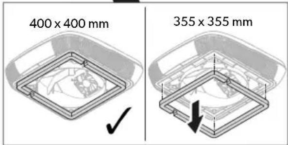
4.

OBVESTILO! Nevarnost poškodb
Prepričajte se, da kabli niso stisnjeni ali preščipnjeni.
Enoto izmenjevalnika toplote poravnajte s strešno enoto.


Consolidated debt information and income tax contributions of the period fiscal year ended February 31, 2017.
RO

4.

ATENTIE! Pericol de defectare


natural_image
Illustration of a trowel and a square object inside a container, no text or symbols present
4.


natural_image
Illustration of a plow and a square object with a handle, no text or symbols presentKatusemooduli paigaldamine
4.

ADB keskosa katte paigaldamine
- Pange ADB keskosa kate siseosa kattele.
19

natural_image
Illustration of a car driving on a road with directional arrows (no text or symbols)natural_image
Architectural line drawing of a building facade with structural elements and ground level indicators (no text or symbols)EL
4

9 Απόρριψη


natural_image
Illustration of a trowel and a square object inside a container, no text or symbols present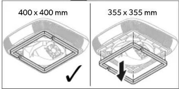
4.


4.

Elements Kontaktligzda Apraksts
dometic.com/sales-offices