Darwin Plus 1310XP - Pressure washer Lavor - Free user manual and instructions
Find the device manual for free Darwin Plus 1310XP Lavor in PDF.

| Brand | Lavor |
| Model | Darwin Plus 1310XP |
| Product type | Professional high-pressure cleaner |
| Category | Hot/cold water high-pressure cleaner |
| Maximum supply water temperature | 40 °C |
| Detergent tank capacity | 3.5 L |
| Diesel fuel tank capacity | 15 L |
| Fuel type | Diesel (road diesel without additives) |
| Vibrations transmitted to the operator | 2.2 m/s² |
| Recoil force at the gun | 43 N |
| Minimum required water flow | 15 L/min |
| Maximum inlet water pressure | 1 MPa |
| Hot water function | Yes, with boiler |
| Automatic shut-off system (Total Stop) | Yes |
| Safety devices | Safety trigger gun, motor protection, bypass valve |
| Weekly maintenance | Check and clean water inlet filter |
| Monthly maintenance | Clean high-pressure nozzle |
| Maintenance every 100 hours | Check hydraulic circuit, oil level, electrodes, filters |
| Maintenance every 300 hours | Pump oil change, replace electrodes/diesel nozzle, descale heating coil |
| Recommended pump oil | SAE 20W40 mineral, 70 g |
Frequently Asked Questions - Darwin Plus 1310XP Lavor
User questions about Darwin Plus 1310XP Lavor
0 question about this device. Answer the ones you know or ask your own.
Ask a new question about this device
Download the instructions for your Pressure washer in PDF format for free! Find your manual Darwin Plus 1310XP - Lavor and take your electronic device back in hand. On this page are published all the documents necessary for the use of your device. Darwin Plus 1310XP by Lavor.
USER MANUAL Darwin Plus 1310XP Lavor
EN • WARNING: read the instructions carefully before use.
SK • POKYNY NA MONTÁŽ
SL • NAVODILA ZA MONTAŽO
FI • ASENNUSOHJE
SV • MONTAGEINSTRUKTIONPÅ FÖRFRÅGAN
NO • MONTERINGSVEILEDNING
natural_image
Technical illustration of a car interior with handrails and structural components, showing motion direction (no text or symbols)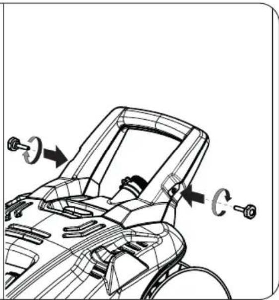
natural_image
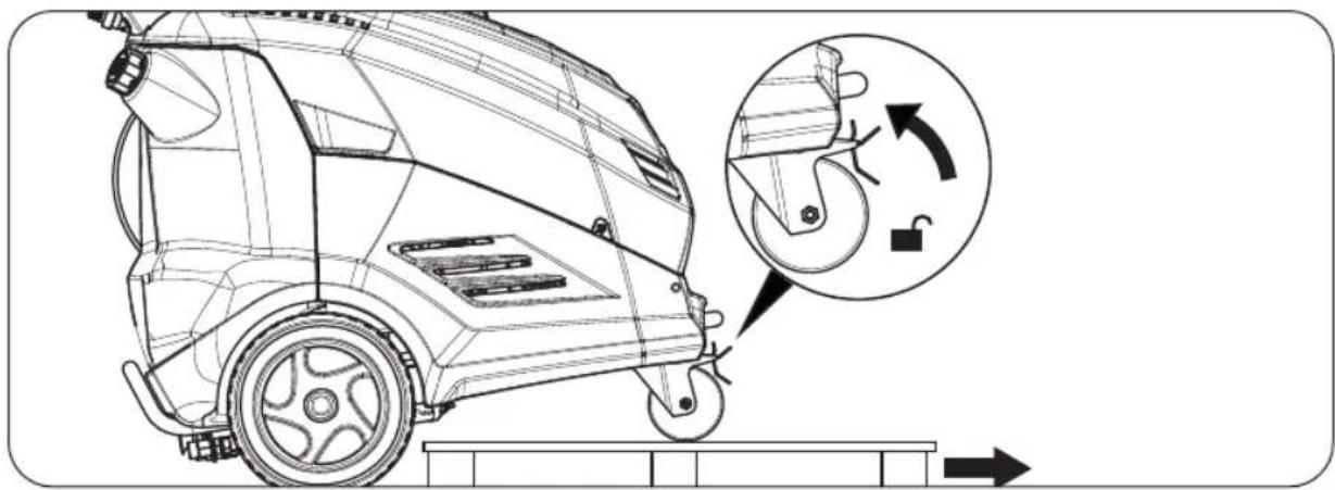
Technical line drawing of a car interior showing steering wheel and seat components (no text or symbols)IT • DISIMBALLO. EN • UNPACKING. FR • DEBALLAGE. ES • DESEMBALAJE. CS • BALENÍ. DA • UDPAKNING. DE • AUSPACKEN DER MASCHINE. EL • ANOŠYŠKEYAŠIA. HU • KICSOMAGOLÁS. NL • TOESTEL UITZICHT. PL • ODPAKOWANIE. PT • DESEMBALAGEM. SK • VYBALENIE. SL • RAZPAKI-RANJE. FI • PAKKAUKSESTA PURKU. SV • UPPACKNING. NO • UTPAKKING. RU • PACNAKOBKA . BG • PA3OПАКОВАМ. ET • LAHTI PAKKIMINE . HR • SUKLANJANJE AMBALAZE
natural_image
Technical line drawing of a car with wheels and a close-up inset showing gear shift (no text or symbols)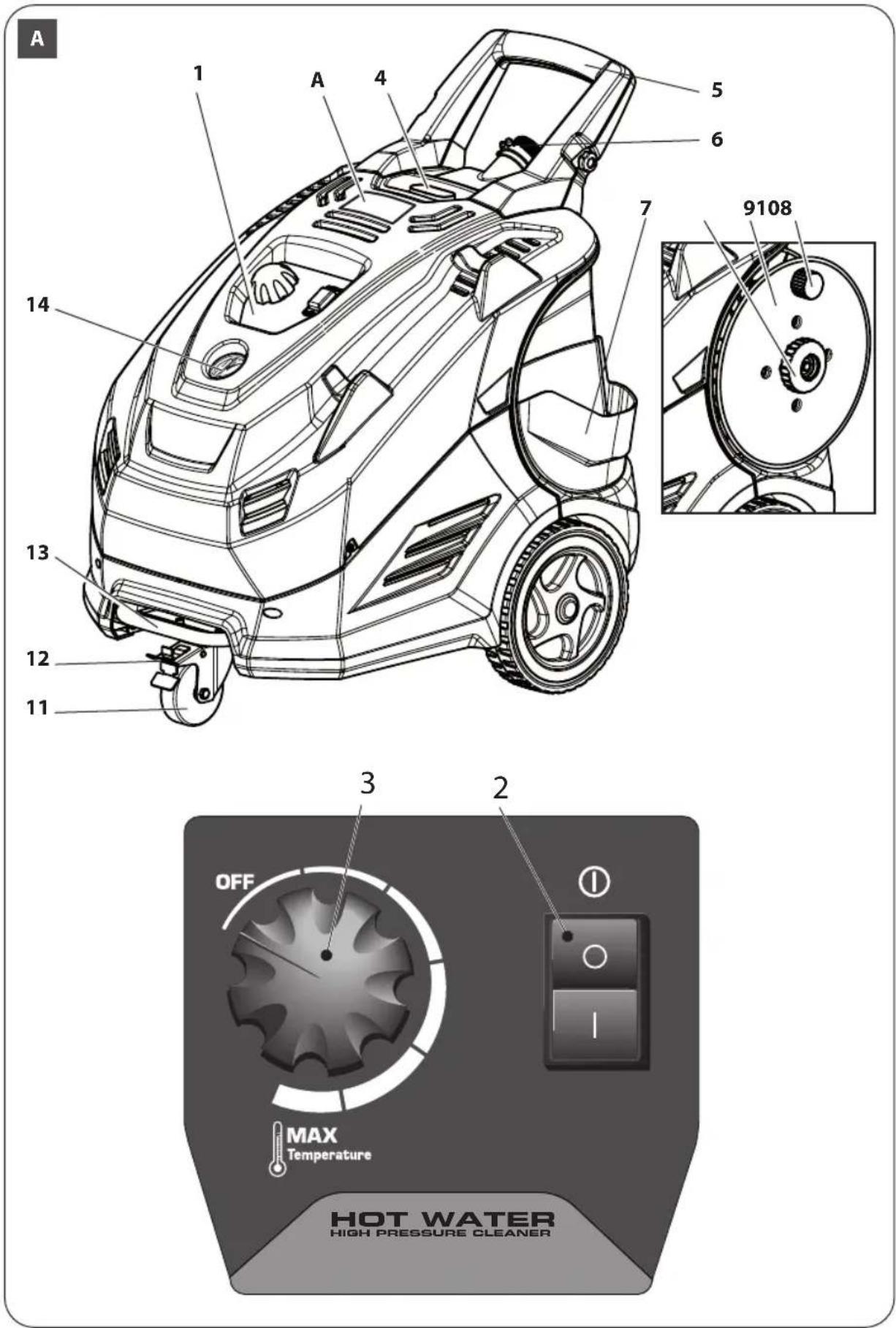
E
E1
E2

natural_image
Diagram of a cable with a circular component and directional arrows, no text or symbols present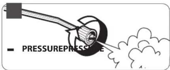
IT • SCHEMA IDRICO
EN·WATER DIAGRAM
FR • SCHEMA HYDRAULIQUE
ES • ESQUEMA HÍDRICO
CS·HYDRAUL.SCHÉMA
DA·VANDORDNING
DE • WASSERUMLAUFSCHEMA
SK • HYDRAULICKÁ SCHÉMA
SL • VODOVODNA SHEMA
FI • VEDENKYTKENTÄKAAVIO
SV·VATTENSCHEMA
NO • VANNSKJEMA
- The appliance can be used for washing surfaces out - doors, whenever pressurised water is required to remove dirt.
- With special optional accessories, it can be used for foaming and sandingblasting, and for washing with a rotary brush for application to the gun.
- The appliance is intended for professional use.
TECHNICAL DATA
(see technical data plate)
1 Power supply
2 Power Consumption
3 Protection class IP (IEC 60259)
4 Working pressure
5 Maximum pressure
6 Max Water Supply Temperature
7 Maximum supply water pressure
8 Nominal flow rate
9 Maximum flow rate
10 Fuel (Burner)
11 Serial number
12 Temp. Max. (Performance data)
13 Burner capacity
14 Sound power level (Guaranteed)
15 Weight
| m/s^2 | 2,2 | Arm vibrations. |
| k | 15% | (Values according to standard: EN 60335-2-79) |
| N | 43 | Recoil force of gun at operating pressure (max). |
| 3,5 | Detergent tank capacity | |
| 15 | Gas oil Fuel tank capacity |
The appliance shall be connected to the electrical net-work providing that the impedance :
Zmax = 0,0924 Ohm
The highest allowed net impedance at the electrical connection point, is not to be exceeded. In case of confusion regarding the power impedance present on your connection, please contact your utilities provider.
SYMBOLS

WARNING: It is important to be careful of the following items.

IMPORTANT NOTE

Use the following personal protection equipment (PPE): Wear protective ear muffs.
SAFETY
WARNING:
Read and keep in mind that indicated in the INSTRUCTION MANUAL - SAFETY WARNINGS.
SAFETY DEVICE
- WARNING: the gun is fitted with a safety catch. Whenever use of the machine is interrupted it is important to operate the safety catch to prevent accidental activation of the jet.
- Safety features: gun equipped with safety locking device, appliance equipped with (Class I) overload cutout, pump equipped with by-pass valve or shutdown device.
- The safety button on the gun is not there to lock the lever during operation, but to prevent its accidental operation.
- WARNING: The appliance is equipped with a motor protection device: in case of device intervention, wait some minutes or, in alternative, disconnect and re-connect the product to the electric system. In case this problem repeats again or if the product does not start again, take the product to the nearest After Sales Service Point
STABILITY
- WARNING: The machine must be always kept on horizontal bases, in a safe and stable way.
USAGE
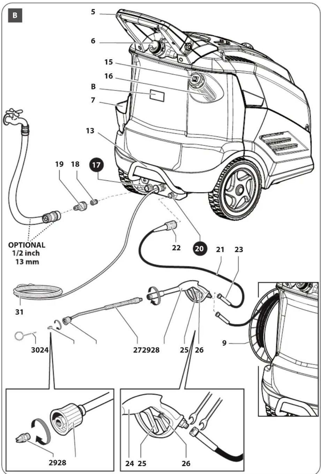
DESCRIPTION OF THE MACHINE
See fig. A B
1 Control panel
2
3

Main switch "1/0" ON/OFF

Knob for temperature adjustment
4 Exhaust
5 Handle
6 Knob for adjusting detergent
7 Pocket for accessories (optional)
8 Hose reel ring nut (optional)
9 Hose reel (optional)
10 Hose reel knob (optional)
11 Swivel wheel
12 Swivel wheel brake
13 Lifting point
14 Pressure gauge
15 Fuel tank cap
16 Fuel fill up filter
17 Water inlet
18 Water inlet filter
19 Water inlet connector
20 Water outlet
21 High pressure hose
22 High pressure hose quick fit connector (side pump)
23 High pressure hose connector (side gun)
24 Water gun
25 Water gun lever
26 Water gun lever safety stop
27 Lance hose
28 Nozzle-holding head
29 High-pressure nozzle
30 Nozzle cleaning hole
31 Electric power cable with plug
See fig. E
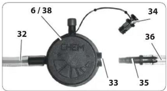
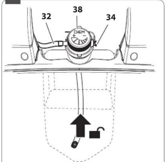
32 Detergent suction hose
33 External detergent tank suction coupling
34 External detergent tank suction cap
35 External detergent tank suction hose fitting
36 External detergent tank suction hose
37 External detergent tank suction hose filter
38 Knob for adjusting detergent
See fig. A B
A Warning plates.
B Identification plate. Indicates the serial number, guaranteed sound power value (in compliance with Directive 2000/14/EC) and main technical characteristics
EN
ASSEMBLY INSTRUCTIONS
See pag. 5
WATER SUPPLY
Water supply collection

WARNING: (symbol) machine not suitable for connection to the potable water mains.
The cleaner can only be connected to the water mains if the water mains is separated by a backflow preventer. Make sure that the hose is at least ∅ 13mm-1/2 inch and that it is reinforced.
- WARNING: Water that has flown through backflow preventers is considered to be non-potable.
IMPORTANT: Only clean or filtered water should be used for intake. The delivery of the water intake tap should be equal to the double of the maximum pump range.
- Minimum delivery rate: 15 l/min.
- Maximum intake water temperature: 40°C
- Max inlet water pressure: 1Mpa
Place the cleaner as close to the water supply system as possible.
Failure to comply with the above conditions causes serious mechanical damage to the pump and the loss of warranty cover.
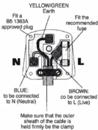
PLUG
HOW TO CONNECT THE CORD TO A U.K. PLUG:
IMPORTANT The wires in the mains lead are coloured in accordance with the following code:
| Blue | Neutral |
| Brown | Live |
| Yellow/Green | Earth |
Please read the instructions given below before connecting the cord to a plug. If in doubt please consult a qualified electrician. As the colours of the wires in the mains lead of this appliance may not correspond with the coloured markings identifying the terminals in your plug, proceed as follows: The wires that is coloured Brown must be connected to the terminal which is marked with the letter L or coloured Red. The wire that is coloured Blue must be connected to the terminal wich is marked with the letter N or coloured Black. Safety points for rewireable or moulded plug: The mains lead of this appliance may be already fitted with a BS1363 13A plug.
- If your socket outlet is not suitable for the plug, then the plug must be removed (cut off if it is a moulded on plug), the flexible cord insulation should be stripped back as appropriate and a suitable 3 pin plug fitted.
- WARNING: Dispose of a plug that has been cut from the power supply cord, as such a plug is hazardous if inserted in a live 13A socket outlet elsewhere in the house. - Should the fuse need to be replaced an ASTA marked fuse, approved to BS1362, of the same rating must be used. - Always replace the fuse cover after fitting a fuse. The plug must NOT be used if the cover is omitted or lost until a replacement is obtained. - Make certain that only the correct fuse cover is used and fitted. - For plugs with detachable fuse cover the replacement must be the same as the
colour insert in the base of the plug, or as directed by the embossed wording on the base of the plug. - If the detachable fuse cover is lost a replacement may be purchased from a Service Centre.
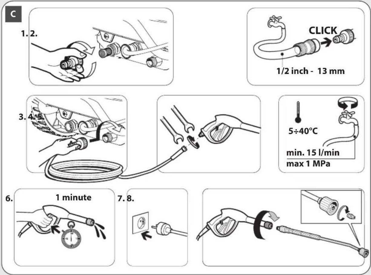
PUT INTO SERVICE
See fig. C
- Check that the master switch is turned to "OFF" and that the water filter is fitted into the pump's inlet pipe.
- Screw the snap connection into place by hand, with - out the aid of tools.
- Connect the water supply hose to the snap connection. The hose must have an inside diameter of at least 13 mm (1/2").
- Connect the high pressure hose to the pump's outlet pipe. Press the high pressure hose coupling fully down and then screw into place by hand without the aid of tools.
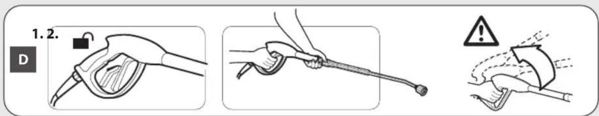
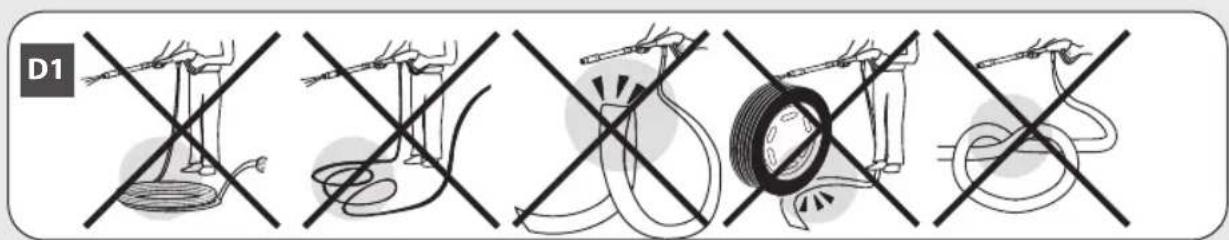
• (fig. D1) Unroll the high-pressure pipe completely. - (fig. 1) If you have a model equipped with hose reel (9), unlock the device by rotating the ring nut in counterclockwise direction (8); unwind the hose quantity that you need, by rotating it in counterclockwise direction by using knob (10); lock the device by rotating the ring nut (8) in clockwise direction.
- Connect the high pressure hose to the gun.
- Turn the water tap fully on. The water temperature absolutely must be below 40^ C.
IMPORTANT: The washer machine has to operate with clean water in order to avoid any damages to the washer machine itself.
- Release the gun safety catch and keep the trigger pressed, allowing the water to flow until all the air has been expelled.
- Fit the lance into the gun.
- Connect the plug to the power socket.
- To start the machine, press the gun trigger and at the same time turn the main switch (2) to "ON""1".
REFILL FUEL
Information on the type of Diesel (gasoil) fuel to be used: Diesel (gasoil) for transport uses and without additives.
Fill up the tank with the fuel indicated on the technical data plate.
Avoid that the tank is empty when the machine is running in order not to damage the fuel pump.
- WARNING: Incorrect fuel shall not used as they as provide hazard.
REFILL DETERGENT
Fill up the detergent tank with the suggested products, suitable for the kind of washing to be carried out.
- WARNING: make use only of liquid detergent, do not absolutely use acid or too much alkaline products.
We suggest you to make use of our products, which have been studied for the use with washer machines.
STARTING UP
- WARNING: Whenever using the high-pressure cleaner, users are urged to hold the gun in the correct position, with one hand on the grip and the other on the spray rod (See fig. D).
Standard Operation (high pressure) with Cold Water
- Check that the temperature adjusting knob (3) is set to off (position "0") and that the nozzle-holding head (28) is not set to detergent supply (see also paragraph "Operation with detergent").
- Restart the water cleaner by setting the main switch (2) to "1".
Note: during this restart phase, the high pressure cleaner will immediately stop operating after the initial peak, as the Total Stop device will take effect.
- Use the cleaner gun's lever (25) to start operation of the high pressure cleaner and thus start cleaning.
- The pressure value can be read on the pressure indicator (14).
Standard Operation (high pressure) with Hot Water
- Check that the nozzle-holding head (28) is not set to detergent supply (see also paragraph "Operation with detergent").
- Restart the water cleaner by setting the main switch (2) to "1".
Note: during this starting-up the water cleaner stops immediately after the starting pickup, because the Total Stop device is activated.
- Rotate the temperature adjusting knob (3) in order to select the wished temperature.
- Operate the water cleaner, thus starting the washing operations; you only need to activate the lever (25) of the water gun.
- The pressure value can be read from the pressure gauge (14).
- If you wish to shift from the operation with hot water to the one with cold water, set the temperature adjusting knob (3) to "0".
EN
- WARNING: In case of operation indoors, adequate ventilation and gas venting must be assured.
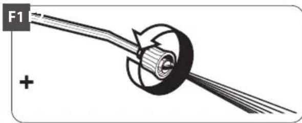
OPERATION WITH DETERGENT
(See fig. E).
Refer to the label on the detergent for instructions on how to use it.
- Turn the master switch (2) to "0".
- (See fig. 31). Suction from the high pressure water cleaner tank: take the cap off (6) and, being careful not to spill any of the liquid (we suggest using a funnel and keeping it for this purpose), fill the tank, following the dosage directions given on the detergent pack; put the cap back on.
- (See fig. 2). Suction from an external tank: remove the cap (34) and put the fitting (35) of the external detergent tank suctioning hose (36) in the coupling (33); put the hose (36) in the external tank containing the detergent at the strength wanted.
- Turn the detergent regulating knob (38) clockwise.
- Operate the nozzle support head (28) as shown in fig. F2 and start up the cleaner again by turning the main switch (2) to or "1". Now operate the lever (25): When the water is fed through, suction and mixing take place automatically. To resume work at high pressure, stop the cleaner by turning the master switch (2) to "0" and adjust the head (28) as shown in fig. F1 (these versions deliver the detergent at low pressure).
- Turn the knob (38) until the amount of product required is delivered. When you have finished using it, turn the knob (38) completely anticlockwise and, if you were using an external tank for suctioning the detergent, take the fitting (35) out of the coupling (33) and put the cap (34) back on.
T.S.
IMPORTANT: (Automatic Stop System), which stops the machine during the bypass phase. To start the water cleaner, it is therefore necessary to set the switch on position "1""ON"; after that press the pistol trigger: the Automatic Stop System will start the machine and will stop it automatically when the trigger is released. It is advisable to put on the safety of the pistol trigger whenever the machine is stopped, in order to avoid unintentional starting.
- Any automatic start of the machine without pressing the gun trigger is attributable to air bubbles in
the water or other similar phenomena which do not imply the existence of any defects in the machine.
- Do not leave the appliance unattended during the standby for more than 5 minutes. Contrarily, for the safety of the appliance it is necessary to re-turn the switch into the "0" OFF position.
- Please check that the coupling of the high pressure hose with the appliance and the gun supplied as standard equipments made correctly, that is to say without any water leak.
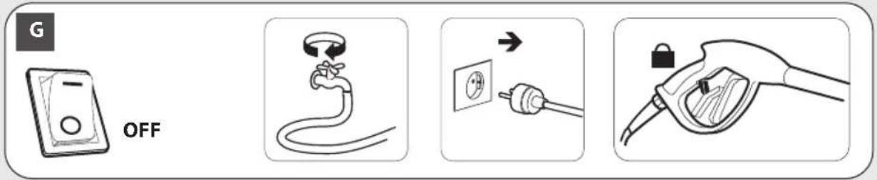
SWITCHING OFF
See fig. G
turn the switch pos. 2 "0" OFF position and wait that the water get completely cold.
In this way you avoid any calcareous deposit and overheatings of the coil and the boiler, which are always dangerous.
IMPORTANT: When the machine is switched off, always discharge the pressure hose, opening the gun.
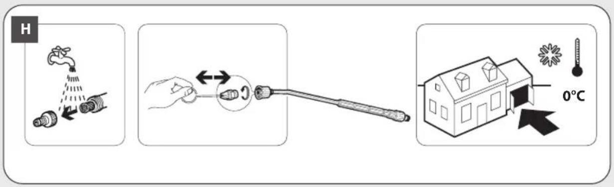
CARE AND MAINTENANCE
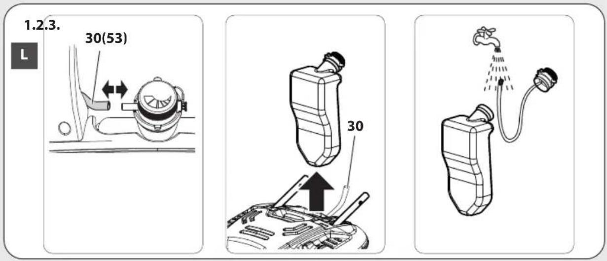
See fig. HL
See table.
- WARNING: the machine shall be disconnected from its power source, by removing the plug from the socket-outlet, during cleaning or maintenance
- WARNING: Do not spray the appliance with water and do not use detergents or aggressive solvents. Machine could be damaged.
- Clean the exterior part of the machine with a dry cloth.
- Always keep the machine clean so that the cooling air can pass through the slits without obstructions..
- When topping up the oil in the pump, use a SAE 20W40 mineral oil. Quantity supplied: 70 gr.
STORAGE
See fig.
- Move the machine only by grasping the carrying handle
- Store the appliance and the accessories in a frost-safe room.
WARRANTY CONDITIONS
All our machines are subjected to strict tests and are covered against manufacturing defects in accordance with applicable regulations. The warranty is effective from the date of purchase. The following are not included in the warranty: - Parts subject to normal wear. - Rubber parts, charcoal, filters and the accessories and optional accessories. - Accidental damage, caused by transport, neglect or inadequate treatment, incorrect or improper use and installation failing - The warranty shall not cover any cleaning operations to which the operative components may be subjected, such as clogged nozzles and filter blocked due to lime stones.
ROUTINE MAINTENANCE
Follow the instructions for "STOPPING WORK" and those provided in the table below.
| MAINTENANCE SCHEDULE | ACTION |
| Every time the cleaner is used | Check the power cord, the high pressure hose, the connectors, the cleaner gun and the lance pipe.Should any of these look damaged, do not use the cleaner for any reason and contact a Qualified Technician. |
| Once a Week• Check the water inlet filter (18) and clean it if necessary.Unscrew the Raccord porte-joint (19) and remove the filter (18).Running water or compressed air is generally all that is needed to clean the filter.In the most difficult cases, use a limescale remover or replace it, contacting a Specialized Technician to buy the spare part.Mount the filter again, following the above steps in reverse order. | |
| Once a Month• Clean the nozzle.To clean the nozzle, it is generally sufficient to insert the pin (30) supplied into the nozzle's hole. If no appreciable results are obtained, contact a Qualified Technician to buy the spare part. The nozzle can be replaced using a 14 mm/0.55" spanner (not supplied). | |
SUPPLEMENTARY MAINTENANCE
Supplementary maintenance should only be carried out by a Qualified Technician, following the table below (guideline only):
| MAINTENANCE SCHEDULE | ACTION | |
| Every 100 hours • Check the pump's hydraulic circuit (water).• Check the pump is firmly secured.• Adjust the electrodes.• Check/top up the pump's oil level. | • Clean the fuel nozzle.• Check/replace the fuel filter.• Check/replace the water filter. | |
| Every 300 hours • Change the pump oil.• Replace the electrodes.• Replace the fuel nozzle.• Check the pump delivery/suction valves.• Check the tightness of pump screws. | • Check the pump's adjustment valve.• Clean the boiler.• Remove any lime scale on the heating element.• Check the safety devices. | |
TROUBLESHOOTING
| FAULT PROBABLE CAUSE REPAIR | ||
| 1. The pump does not start when the switch is pressed. | 1. The plug is not properly connected to the socket.2. The electrical socket is not working.3. The mains voltage is insufficient.4. The gauge of the electrical power lead is too small.5. The pump has cut out. | 1. Connect the plug to the power socket correctly.2. Have the electrical socket checked.3. Check that the system is suitable.4. Refer to the section detailing the electrical connection.5. Turn the switch to ON while keeping the gun lever pressed; if the problem persists contact an authorised service centre. |
| 2. The machine starts, but no water comes out. | 6. Pump, hoses or accessories frozen.7. No water supply.8. Water filter fouled.9. Nozzle fouled. | 6. Allow the pump and hoses to thaw.7. Connect the machine to the water supply system and turn on the tap.8. Remove and clean the filter (see “MAINTENANCE” section).9. Remove the lance from the gun and clean the nozzle with the pin provided. |
| 3. The pump runs but pressurisation does not take place. | 10. Insufficient water.11. Suction filter fouled.12. Pressure regulator valve (if fitted) on minimum pressure setting.13. Lance nozzle worn.14. Suction or delivery valves fouled or worn. | 10. Check that the delivery rate is at least 12 l/min.11. Remove and clean the filter (see “MAINTENANCE” section).12. Increase the pressure by turning the handgrip.13. Replace the lance.14. Contact an authorised service centre. |
| 4. Uneven working pressure. | 15. Lance nozzle fouled or dirty.16. Air in intake water.17. Suction filter fouled.18. Suction or delivery valves fouled or worn.19. Gaskets worn.20. Pressure regulator valve gaskets worn. | 15. Remove the lance from the gun and clean the nozzle with the pin provided.16. Supply the machine with water correctly.17. Remove and clean the filter (see “MAINTENANCE” section).18. Contact an authorised service centre.19. Contact an authorised service centre.20. Contact an authorised service centre. |
| 5. The motor stops suddenly. | 21. Machine’s safety overload cutout has been tripped.22. The gauge of the electrical power lead is too small. | 21. Allow the motor to cool for a few minutes. If the problem persists contact an authorised service centre.22. Refer to the section detailing the electrical connection. |
| 6. Water leaks from the machine. | 23. Leaks from hose reel (if used).24. Leaks from intake coupling.25. Leaks from pump. | 23. Tighten the couplings; if the problem persists contact an authorised service centre.24. Make sure that the coupling has been fitted correctly (See illustrations in the “INSTALLATION” section).25. Contact an authorised service centre. |
| 7. Abnormal noise. 26. | Suction filter fouled.27. Intake water temperature too high.28. Suction or delivery valves fouled or worn.29. Bearings worn. | 26. Remove and clean the filter (see “MAINTENANCE” section).27. Reduce the temperature below 40°C.28. Contact an authorised service centre.29. Contact an authorised service centre. |
| 8. Water in the oil. 30. O-ring seals worn. 30. Contact an authorised service centre. | ||
EN
| 9. The machine restarts with the gun released (versions with T.S.). | 31.Water leak from hose - gun connection (except models with hose and gun supplied readyconnected).32. Air in intake water.33.Water leak from the gun.34.Water leak from the pump. | 31. Tighten the connection with 2 spanners.32. Supply the machine with water correctly.33. Contact an authorised service centre.34. Contact an authorised service centre. |
| 10.The machine does not suck in detergent. | 35. Tank empty.36. Lance handgrip on high pressure setting (if present).37. Transparent suction pipe damaged or disconnected. | 35. Fill the tank.36. Move it to the low pressure setting by rotating the head nozzle.37. Reconnect the pipe. If the problem persists contact an authorised service centre. |
| 11.Turning on the burner switch the boiler doesn’t start. | 38.No fuel39.Fuel filter is clogged40.Fuel pump is either blocked or burnt out41.Damaged thermostat42.Ignition spark insufficient or totally lacking43.The space among the electrodes is not correct | 38.Check the level in the tank and check whether the rigid suction pipe is clean39.Replace the line filter40.Replace it.41.Replace it.42.Contact an authorised service centre.43.Contact an authorised service centre. |
INDICATIONS GÉNÉRALES
UTILISATION PRÉVUES
FONCTIONNEMENT AVEC DÉTERGENT
(fig. 3).
CONDITIONS DE GARANTIE
① Interruptor general "1/0" ON/OFF
3
VED ARBEJDETS AFSLUTNING
se fig. C
① Interruptor geral "1/0" ON/OFF
3
ORDINÆRT VEDLIKEHOLD
Utfør arbeidet som forklares i avsnittet STANS. Følg tabellen nedenfor.
EKSTRAORDINÄRT VEDLIKEHOLD
Det ekstraordinære vedlikeholdet må kun utføres av Kvalifisert Personale. Følg tabellen nedenfor (veiledende data):
DIFFERENZIA I RIFIUTI SEPARATE THE WASTE
cod. 22001-06336 (7.700.0658-01 10/2022)