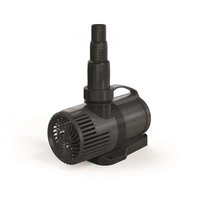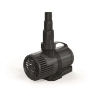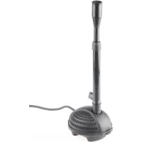
PondoRell 5000 UVC - Water pump Pontec - Free user manual and instructions
Find the device manual for free PondoRell 5000 UVC Pontec in PDF.


| Brand | Pontec |
| Model | PondoRell 5000 UVC |
| Category | Water pump |
| Rated voltage | 230 V AC |
| Mains frequency | 50 Hz |
| Power consumption | 35 W |
| UVC lamp type | 9 W TC-S (UV-C) |
| Max delivery capacity | 1100 l/h |
| Max delivery head | 2.3 m |
| Max immersion depth | 2 m |
| Max pond volume (without fish) | 5000 l |
| Max pond volume (with fish) | 2500 l |
| Permissible water temperature | +4 °C to +35 °C |
| Mains cable length | 10 m |
| Dimensions (L × W × H) | 380 × 290 × 160 mm |
| Weight | 4.5 kg |
| Discharge connection | G 12 |
| Main functions | Water jet pump, filtration, UVC pre-clarification, flow regulation, adjustable outlet for stream |
| Filter elements | Filter foams, biological elements, gravel bag |
| Maintenance and cleaning | Clean the housing, filter elements, pump and UVC pre-clarifier regularly; replace UVC lamp after 8000 hours |
| Safety | 30 mA residual current device recommended; do not use with dimmer; disconnect before servicing |
| Wear parts | Filter elements, operating unit, UVC lamp, quartz glass, O-ring |
| Warranty | 2 years (excluding wear parts) |
Frequently Asked Questions - PondoRell 5000 UVC Pontec
User questions about PondoRell 5000 UVC Pontec
0 question about this device. Answer the ones you know or ask your own.
Ask a new question about this device
Download the instructions for your Water pump in PDF format for free! Find your manual PondoRell 5000 UVC - Pontec and take your electronic device back in hand. On this page are published all the documents necessary for the use of your device. PondoRell 5000 UVC by Pontec.
USER MANUAL PondoRell 5000 UVC Pontec
EN Operating instructions
FR Notice d'emploi
natural_image
Technical line drawing of two mechanical device components with vertical posts and ventilation slots (no text or symbols)A
PondoRell 3000 UVC
natural_image
Technical line drawing of a mechanical component with ventilation slots and a labeled part (1), no text or symbols present.PondoRell 5000 UVC
natural_image
Technical line drawing of a mechanical component with no visible text or symbols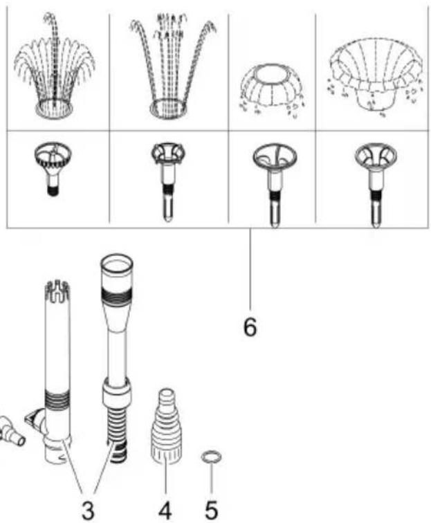
text_image
Technical diagram showing exploded and assembled views of a water filter component with numbered parts labeled 3, 4, and 5.PRL0001
B
text_image
≥ 2 m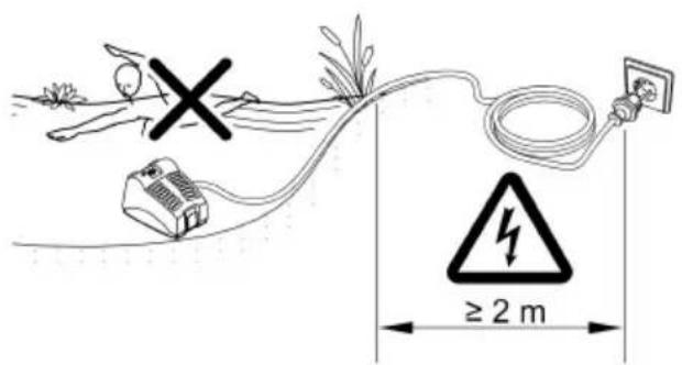
text_image
≥ 2 mPRL0003
text_image
C 1. 2. 3. 4. 5. PRL0033
text_image
D E PVO0024 1. PRL0004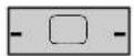
F
text_image
ON OFFPRL0036
PondoRell 3000 UVC
G
text_image
1. max. 5° 2.
flowchart
graph TD
    A["Step 4: Gear assembly"] --> B["Step 3: Gear assembly with meshing"]
    B --> C["Step 3: Motor assembly with gear"]
    C --> D["Step 3: Gear assembly with gear"]
    D --> E["Step 3: Gear assembly with gear"]
    E --> F["Step 3: Gear assembly with gear"]
PRL0005
H
flowchart
graph TD
    A["1. Motor with meshed cable"] --> B["2. Panel with circuit board"]
    B --> C["3. Cable with cable"]
    C --> D["4. Motor assembly with wiring"]
    D --> E["5. Display unit with cable and plug"]
    style A fill:#f9f,stroke:#333
    style E fill:#bbf,stroke:#333
PRL0006
|
text_image
max. 5° 1. 2.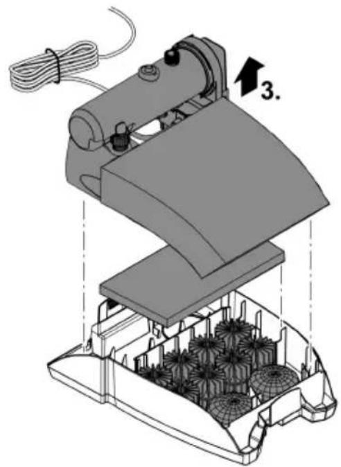
natural_image
Technical illustration of a sewing machine with spools and wiring, no visible text or symbolsPRL0037
J
text_image
Technical diagram illustrating five steps of a robotic device assembly with labeled components and component layouts.PRL0038
K
text_image
Technical diagram showing mechanical assembly steps with numbered labels indicating different componentsPCR0009
L
text_image
Technical diagram of a mechanical device with numbered annotations indicating parts of the assembly.PCR0010
M
text_image
1.
text_image
click 2.PCR0011
N
text_image
1.
text_image
Diagram showing a hand operating a mechanical device with labeled parts and directional arrows indicating motion or operation.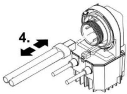
text_image
4.
text_image
Technical diagram of a mechanical device with labeled parts and warning symbol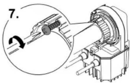
text_image
7.PCR0012
Original manual. This manual belongs with the unit and must always be passed on together with the unit.
WARNING
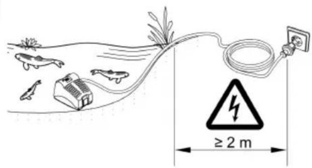
▶ Disconnect all electrical devices in the water from the power supply before reaching into the water. Otherwise there is a risk of severe injuries or death by electrocution.
▶ Disconnect the power plug before carrying out any work on the unit.
This unit can be used by children aged 8 and above and by persons with reduced physical, sensory or mental capabilities or lack of experience and knowledge if they are supervised or have been instructed on how to use the unit in a safe way and they understand the hazards involved. Do not allow children to play with the unit. Only allow children to carry out cleaning and user maintenance under supervision.
Safety information
Correct electrical installation
- Special regulations apply for electrical installation in outdoor spaces. Only a qualified electrician may perform the electrical installation.
- The qualified electrician has the necessary professional training, knowledge and experience to perform electrical installation in outdoor spaces. The electrician can detect potential dangers and knows how to adhere to regional and national standards, regulations and directives.
- For your own safety, please consult a qualified electrician.
- Only connect the unit if the electrical data of the unit and the power supply correspond.
- Only plug the unit into a correctly installed outlet. Ensure that the unit is fused for a rated fault current of max. 30 mA by means of a fault current protection device.
- Extension cables and power distributors (e.g. outlet strips) must be suitable for outdoor use (splash-proof).
- Protect the plug connection from moisture.
Safe operation
- Do not use the unit, if electrical lines or the housing are damaged.
- Never operate the UVC lamp outside the housing or in a damaged housing. The ultraviolet radiation can burn the skin and eyes.
- A damaged connection cable cannot be replaced. Dispose of the unit.
- Do not carry or pull the unit by its power cable.
- Route lines in such a way that they are protected from damage and do not present a tripping hazard.
- Never carry out technical changes to the unit.
- Only carry out work on the unit that is described in this manual.
- Only use original spare parts and accessories.
Product Description
Overview
| ☐ A | PondoRell 3000 UVC / 5000 UVC | Quantity |
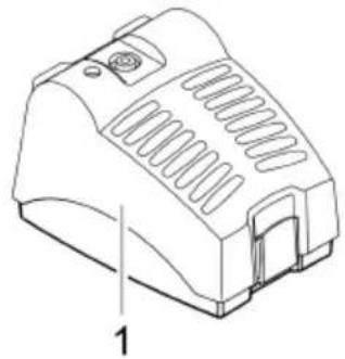
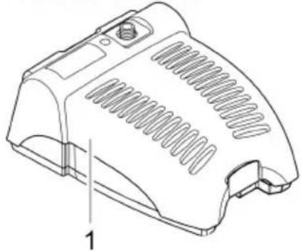
| 1 | Filter housing with filter pump and UVC clarifying unit | 1 |
| 2 | Ball joint with adjustable outlet (∅ 9 mm) | 1 |
| 3 | Telescopic pipe, 2-part, consisting of an external and an internal pipe | 1 |
| 4 | Stepped hose adapter, 12 mm, 19 mm, 25 mm | 1 |
| 5 | Flat seal for ball joint (2) or stepped hose adapter (4) | 1 |
| 6 | Nozzles | 4 |
Properties
PondoRell 3000 UVC / 5000 UVC is a fountain pump with a filter function for garden ponds and prefabricated basins.
- Compact filter unit with UVC technology and 4 different filter materials.
- Different nozzles for attractive fountains.
- Telescopic pipe for adapting the nozzle to the pond surface.
- Separately adjustable outlet for operating waterspouts or small water courses.
- Individual adjustment of water volume and fountain height.
- Installation completely under water – no unwelcome disruptions of the pond appearance.
- Visual function check of the UVC clarifying unit.
Intended use
Only use the product described in this manual as follows:
- For cleaning garden ponds.
- For operation with clean water.
- Operate the product in compliance with the technical data. (→ Technical data)
The following restrictions apply to the unit:
- This product is not suitable for general lighting, but is only intended for the purpose described here.
- Do not use in swimming ponds.
- Never use the unit with fluids other than water.
- Never run the unit without water.
- Do not use for commercial or industrial purposes.
- Do not use in conjunction with chemicals, foodstuff, easily flammable or explosive substances.
Installation and connection
Use as a fountain pump
How to proceed:
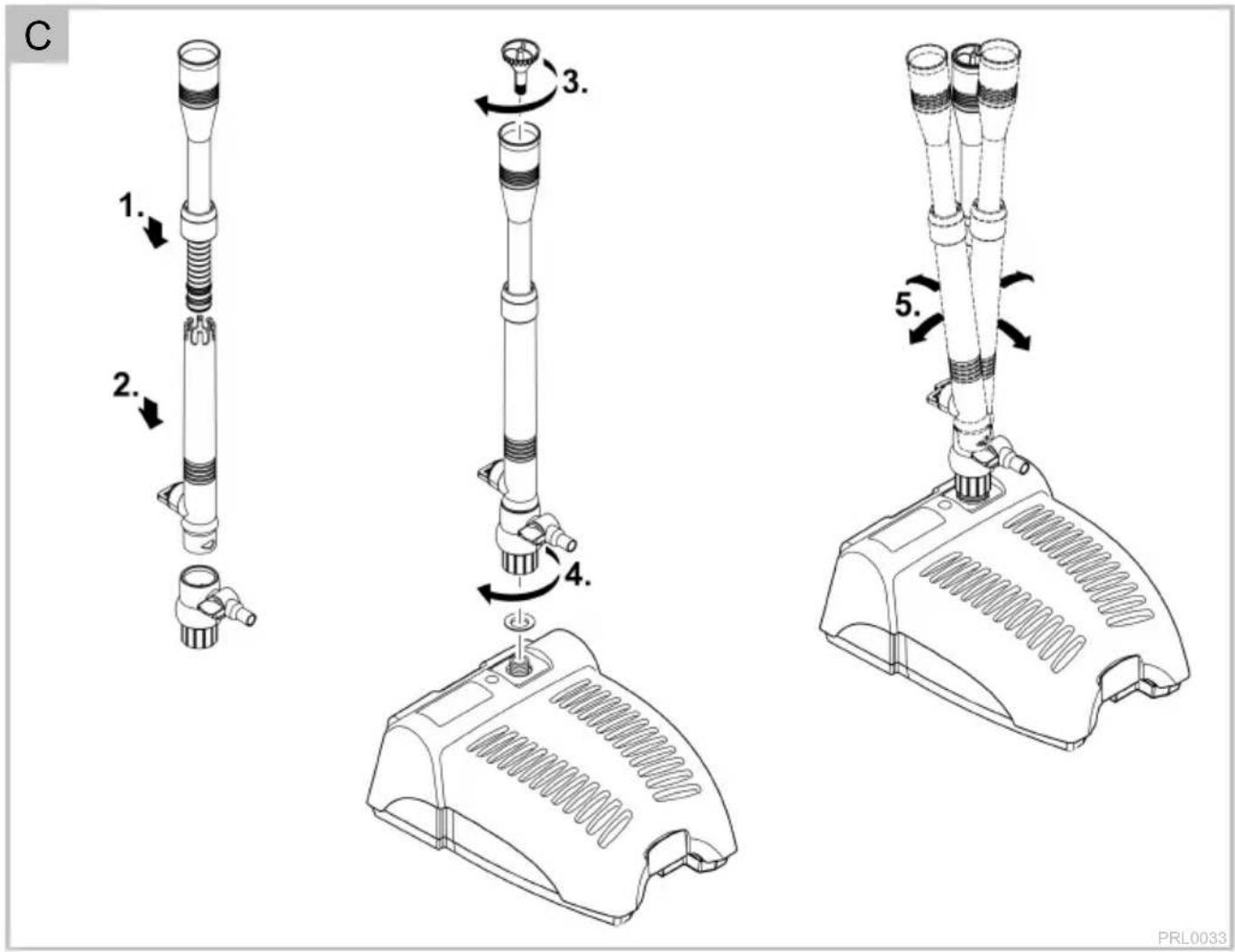
□ B, C
- Assemble the telescopic pipe.
- Insert the internal pipe into the external pipe and secure with the retaining collar.
- Fit the telescopic pipe onto the ball joint.
- Ensure that the control valve on the telescopic pipe and the separately adjustable outlet on the ball joint are aligned opposite each other so that water can flow out of the outlet of the ball joint.
- Insert the desired nozzle into the telescopic pipe and screw it in.
- Some nozzles have to be turned to adjust the shape of the fountain.
-
Screw the ball joint onto the pump outlet and hand-tighten.
-
Vertically align the telescopic pipe via the ball joint.
-
Place the unit in the pond on horizontal, firm and sludge-free ground and ensure that it is completely covered by water.
The separately adjustable outlet (∅ 9 mm) on the ball joint can be used for feeding an optional water course.
- EN -
Use as a water course pump or filter pump
How to proceed:
B, E
- Screw the stepped hose adapter with the O ring onto the pump outlet and hand-tighten.
- Place the unit in the pond on horizontal, firm and sludge-free ground and ensure that it is completely covered by water.
- Maximum installation depth: 2 m below the surface of the water.
Commissioning/start-up
NOTE
The unit will be destroyed if it is operated with a dimmer. It contains sensitive electrical components.
▶ Do not connect the unit to a dimmable power supply.
How to proceed:
□F
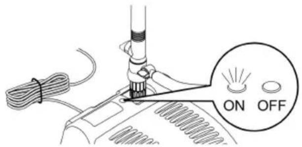
- Switching on: Plug the power plug into the outlet.
- The unit switches on immediately.
- The control lamp is lit.
- Switching off: Pull the power plug from the outlet.
Adjustments
□D
- Turn the control valve on the telescopic extension to achieve the desired spray pattern.
- If necessary, turn the control valve on the ball joint to achieve the desired flow rate.
Maintenance and cleaning
Carry out the cleaning and servicing measures described in the following at regular intervals in order to ensure proper function of the individual units. The cleaning cycle depends on the degree of soiling/pollution of the garden pond. Follow the warning and safety information!
WARNING
Risk of severe injuries or death by electric shock.
▶ Disconnect all electrical devices in the water from the power supply before reaching into the water.
▶ Disconnect the unit from the mains before you start working on it.
Cleaning the housing
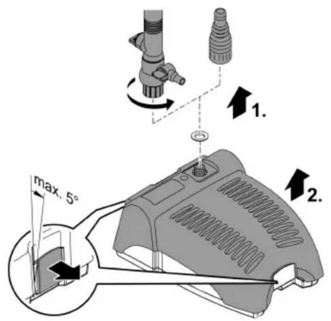
Opening and cleaning the housing
How to proceed:
□ G, I
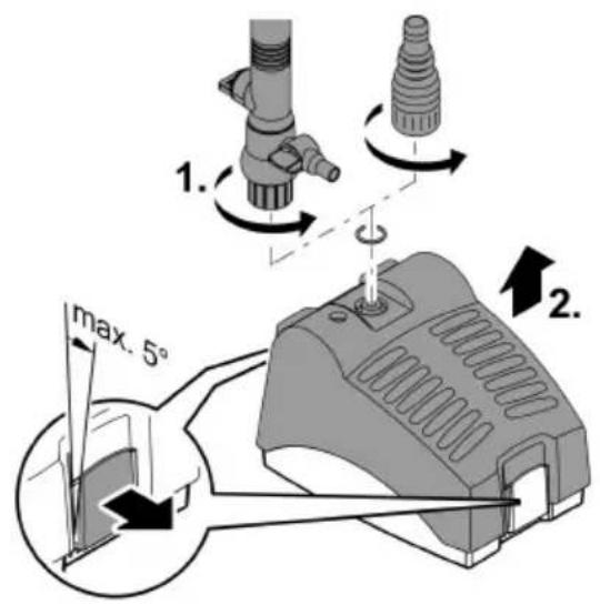
- Unscrew the ball joint or stepped hose adapter.
- On both sides, pull off the clamps by max. 5^ and remove the top filter section.
- Remove the foam filter, UVC clarifying unit, bio-surface elements and gravel bag.
- Use a brush to clean the bottom filter section and top filter section under clear water.
- Wash out the filter media (foam filters, bio-surface elements and gravel bag) under running water.
- Do not use chemical cleaning agents, as they would kill the micro-organisms in the filter media and would therefore reduce the filtration effect.
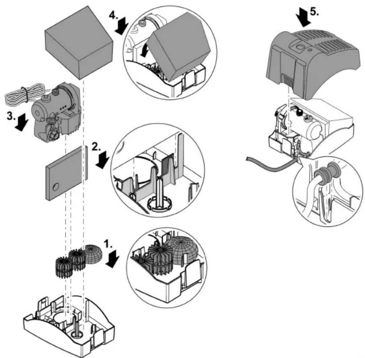
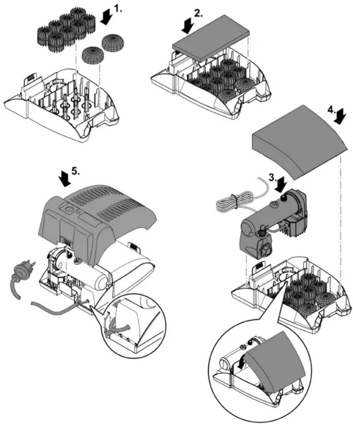
Closing the housing
How to proceed:
H, J
-
Place the top filter section on the bottom filter section and push it in place until the clamps engage.
-
Place the bio-surface elements and gravel bag in the bottom filter section.
- Place the fine foam filter in the bottom filter section.
- Place the UVC clarifying unit with the pump in the bottom filter section.
- Place the foam filter in the holder of the bottom filter section.
- Ensure that the cable feedthrough with the connection cable is positioned in the cable slot of the bottom filter section.
Cleaning the pump
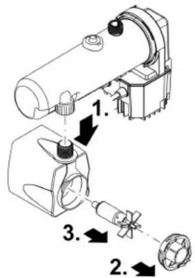
For cleaning it is necessary to remove the pump and UVC clarifying unit from the housing. ( Cleaning the housing) How to proceed:
□K
- Unscrew the union nut (remains connected to the UVC clarifying unit), then pull off the pump downwards.
- Unscrew the pump lid by turning counter-clockwise, and remove (bayonet closure).
- Pull out the impeller unit (magnetic holder).
- Rinse all parts. (Not shown)
- Reassemble the unit in the reverse order.
Clean UVC clarifier
For cleaning it is necessary to remove the pump and UVC clarifying unit from the housing. ( Cleaning the housing)
CAUTION
The ultra-violet radiation of the UVC lamp can burn your eyes and skin.
▶ Never operate the UVC lamp outside its housing.
▶ Disconnect the unit from the mains before starting maintenance or before replacing the UVC lamp.
CAUTION
The quartz glass and UVC lamp could break and result in cuts.
- Carry out all work on the UVC clarifier carefully to avoid cutting injuries.
- Avoid vibrations, impacts and hectic movements to prevent the breaking of glass.
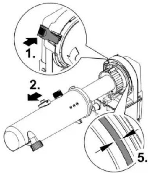
Open and clean the UVC water housing
How to proceed:
□L
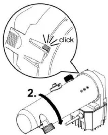
- Press on the engagement lug at the unit head, then turn the UVC water housing counter-clockwise against the stop.
- Carefully remove the water housing from the unit head.
- Clean the water housing under running water. (Not shown)
- Clean the quartz glass outer face with a moist cloth and check for damage. (Not shown)
- Check the O ring at the unit head for damage.
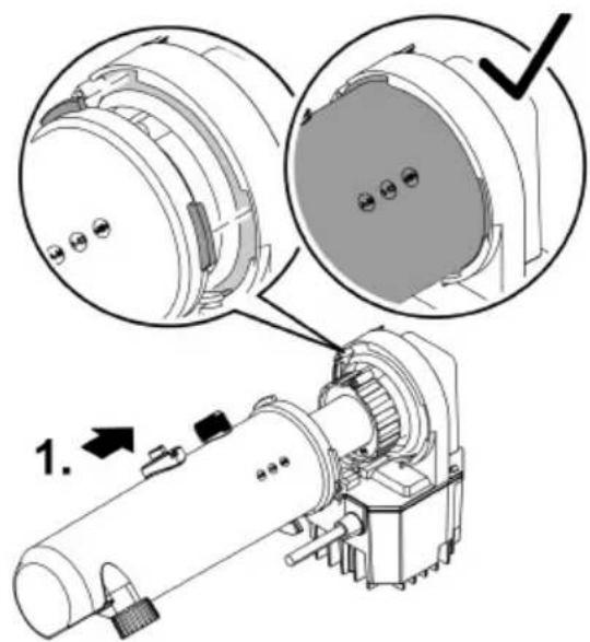
Close the UVC water housing
How to proceed:
□M
- Carefully push the UVC water housing onto the unit head such that tenon and groove of the bayonet closure engage.
- Turn the UVC water housing clockwise against the stop and allow to engage.
Exchange the UVC lamp
Replace the UVC lamp after max. 8000 operating hours.
- To replace the UVC lamp, remove the UVC clarifying unit and refit after completion of the work. (→ Cleaning the UVC clarifying unit)
- Ensure that the identification and capacity data of the lamps used correspond to the information on the unit type plate. (→ Technical data)
- Prior to inserting the UVC lamp, check the quartz glass and O ring for damage and replace if necessary.
How to proceed:
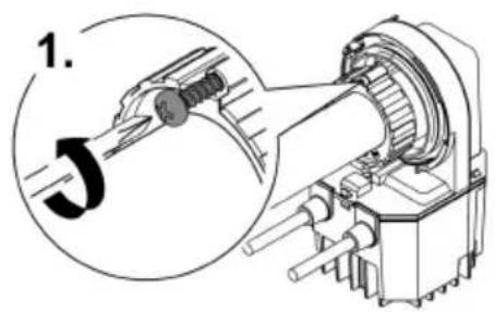
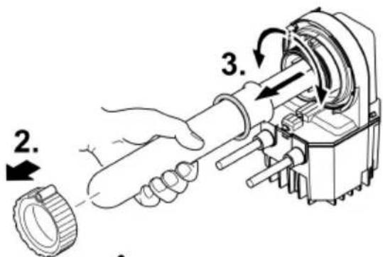
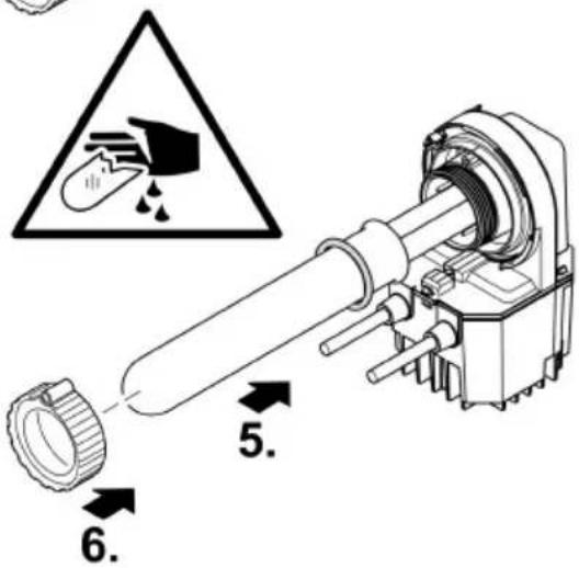
□ N
- Turn out the self-tapping screw once you have removed the UVC water housing.
- Turn the union nut off the unit head by turning counter-clockwise.
- Pull off the quartz glass and the O-ring while slightly turning the unit head.
- Pull out the UVC lamp and replace.
- Insert the quartz glass including the O ring against the stop in the unit head.
- Tighten the clamping screw clockwise up to the stop.
- Turn in and tighten the self-tapping screw.
- Close the UVC water housing. ( Cleaning the UVC clarifying unit)
Storage/winter protection
Take the unit out of operation at water temperatures below +4 °C or, at the latest, when freezing temperatures are to be expected.
- Drain the water remaining in the unit, in the hoses, pipe and connections as much as possible.
- Store the unit in a dry and frost-free place.
Malfunction remedy
| Malfunction | Possible cause | Remedy |
| Unit is not operating | No mains voltage | Check the mains voltage. |
| Delivery or fountain height insufficient or not consistent,Cloudy water | Flow regulator excessively throttled | Set flow regulator |
| Nozzle blocked | Unscrew and clean the nozzle insert | |
| Excessive pressure losses in the hoses | Reduce hose length and connecting parts to a minimum, route hoses as straight as possible | |
| Intake openings blocked | Clean housing | |
| Filter media clogged | Clean filter media | |
| Impeller unit blocked | Clean the impeller unit | |
| Pond extremely dirty | Remove algae and leaves from the pond, change the water | |
| The quartz glass is soiled. | Remove UVC clarifying unit and clean the quartz glass | |
| The UVC lamp is not lit | The UVC lamp overheats. The temperature monitor turned off the UVC lamp | After cooling down, the UVC lamp switches on again automatically |
| The UVC lamp is defective | Replace the UVC lamp. | |
| The UVC lamp is not inserted into the socket properly | Insert the UVC lamp correctly into the socket | |
| Unit switches off after a short running period | Water temperature too high | Observe the maximum water temperature of +35 C |
Technical data
| Area | PondoReII 3000 UVC | PondoReII 5000 UVC | |
| Rated voltage | V AC | 230 | 230 |
| Mains frequency | Hz | 50 | 50 |
| Power consumption | W | 20 | 35 |
| UVC lamp type | 7 W TC-S (UV-C) | 9 W TC-S (UV-C) | |
| Connection, pressure side | G12 | G12 | |
| Maximum pump capacity | l/h | 600 | 1100 |
| Maximum immersion depth | m | 2 | 2 |
| Maximum head height | m | 1.3 | 2.3 |
| Maximum pond volume without fish | l | 3000 | 5000 |
| Maximum pond volume with fish | l | 1500 | 2500 |
| Permissible water temperature | °C | +4 ... +35 | +4 ... +35 |
| Mains connection cable length | m | 10 | 10 |
| Dimensions without connections (L × W × H) | mm | 250 × 185 × 160 | 380 × 290 × 160 |
| Weight | kg | 3.3 | 4.5 |
Symbols on the unit
 | The unit is dust-tight and water-tight down to 2 m. | |
 | Dangerous UVC radiation | |
 | Remove the unit in the event of freezing temperatures | |
 | Fragile, handle with care. Risk of cuts. | |
 | Do not dispose of the unit with normal household waste | |
 | Read the operating instructions | |
Wear parts
- Filter media
- Impeller unit
• UVC lamp, quartz glass and O ring for quartz glass
Disposal
NOTE

Do not dispose of this unit with household waste.
▶ Dispose of the unit by using the return system provided for this purpose.
▶ Render the unit unusable by cutting the cables.
▶ Dispose of UVC lamps by availing of the take-back system in place for this purpose. Foam filters and seals no longer used can be disposed of with the household waste.
Guarantee conditions
PfG grants a 2 year guarantee from the date of sale on proven material and manufacturing faults. Wear parts such as bulbs etc. are exempted from the guarantee. Prerequisite for our guarantee is the presentation of the purchase receipt. Our guarantee will become null and void if the unit is misused, electrically or mechanically damaged by inappropriate use and improper repair by non-authorised workshops. Repairs are reserved for workshops authorised by PfG or by PfG itself. In the case of warranty claims, please return the defective unit or part freight paid to PfG together with a description of the fault and the purchase receipt. PfG reserves the right to invoice repair costs. PfG is not liable for transport damage. Any damage must be claimed against the carrier. Further claims of whatever type, especially consequential damage, are excluded. This guarantee does not affect the final customer's claims against the dealer.
text_image
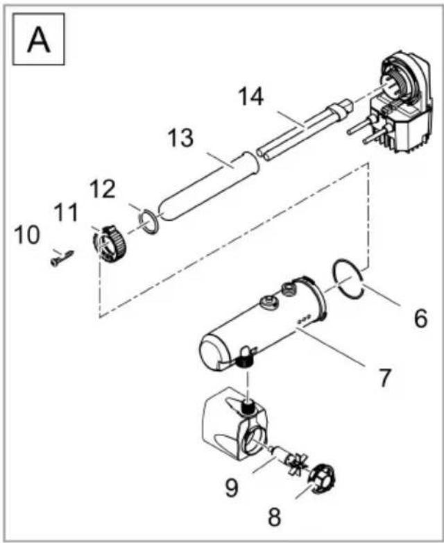
Exploded view diagram of a mechanical assembly with numbered parts and labeled section APRL0008
| Pos. | PondoRell 5000 UVC |
| 1 | 28666 |
| 2 | 35836 |
| 3 | 11349 |
| 4 | 29386 |
| 5 | 28224 |
| 6 | 73490 |
| 7 | 35872 |
| 8 | 35770 |
| 9 | 35755 |
| 10 | 27891 |
| 11 | 12049 |
| 12 | 73481 |
| 13 | 22622 |
| 14 | 22610 |
| A | 72529 |
text_image
A 10 11 12 13 14 6 7 9 8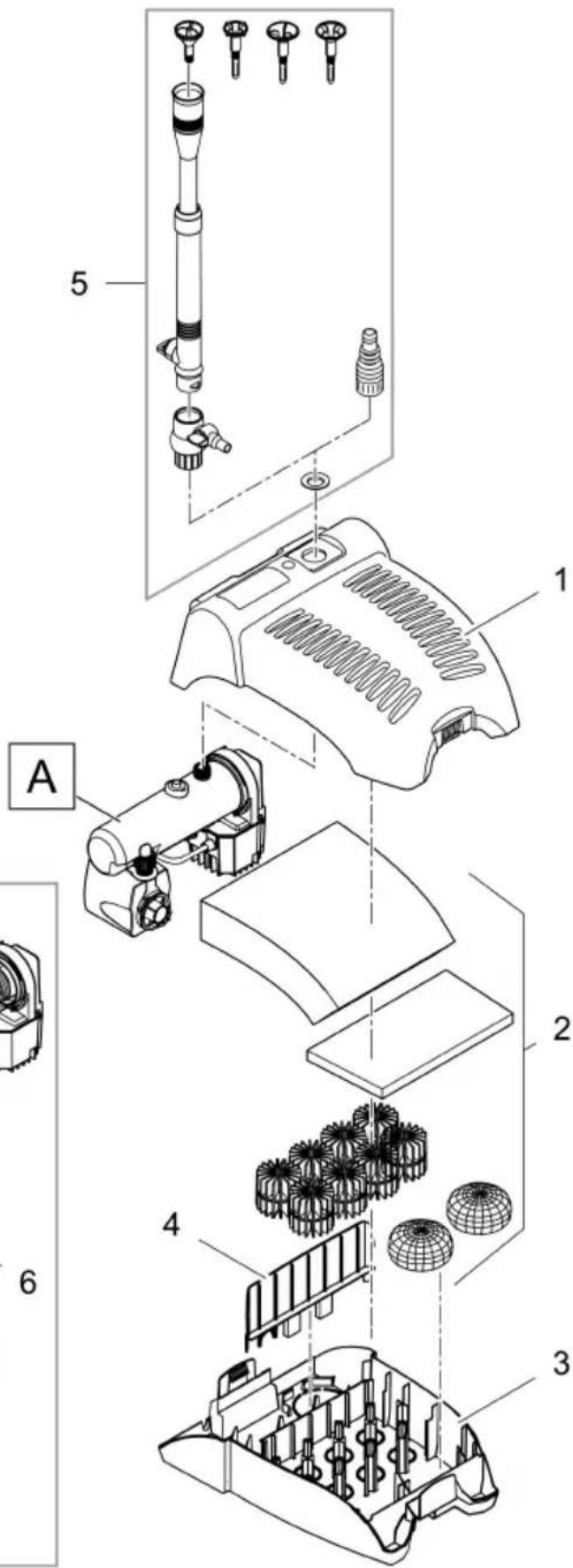
text_image
Exploded view diagram of a mechanical assembly with numbered parts and labeled section APRL0047