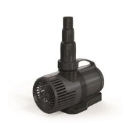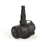
PondoMax Eco 20000 Control - Water pump Pontec - Free user manual and instructions
Find the device manual for free PondoMax Eco 20000 Control Pontec in PDF.


| Product type | Pond water pump |
| Model | PondoMax Eco 20000 Control |
| Brand | Pontec |
| Use | Pumping pond water for filters, waterfalls and streams |
| Power supply | 220-240 V AC, 50/60 Hz |
| Power consumption | 50 - 190 W |
| Max. flow rate | 20 000 l/h |
| Max. head | 7.5 m |
| Max. immersion depth | 4 m |
| Protection rating (pump) | IP68 |
| Protection rating (controller) | IP44 |
| Dimensions (L × W × H) | 255 × 130 × 170 mm |
| Weight | 5.1 kg |
| Power cable length | 2 m |
| Pump-controller cable length | 8 m |
| Suction / discharge connection | G2 thread, hose connector 32, 38 or 50 mm |
| Max. particle size | up to 8 mm |
| Filter inlet area | 310 cm² |
| Water temperature (submerged) | +4 to +35 °C (operation) |
| Ambient temperature (dry installation) | +4 to +30 °C (natural convection), +4 to +40 °C (forced cooling) |
| Flow rate adjustment | Electronic controller: 0, 25, 50, 60, 70, 80, 90, 100 % |
| Wear parts | Operating unit (rotor block) |
| Cleaning and maintenance | Tool-free disassembly, cleaning with clear water, at least 2 times per year |
| Protection | Residual current device (RCD) 30 mA max. mandatory |
| Warranty | 3 years (excluding wear parts) |
Frequently Asked Questions - PondoMax Eco 20000 Control Pontec
User questions about PondoMax Eco 20000 Control Pontec
0 question about this device. Answer the ones you know or ask your own.
Ask a new question about this device
Download the instructions for your Water pump in PDF format for free! Find your manual PondoMax Eco 20000 Control - Pontec and take your electronic device back in hand. On this page are published all the documents necessary for the use of your device. PondoMax Eco 20000 Control by Pontec.
USER MANUAL PondoMax Eco 20000 Control Pontec
natural_image
Technical line drawing of an electric motor connected to a control unit (no text or symbols present)
A
text_image
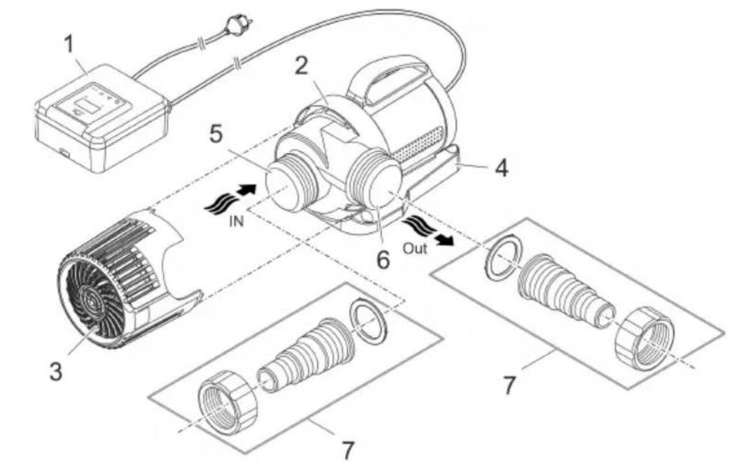
Exploded diagram of an electric motor showing internal components and assembly steps with labeled parts 1 through 7.PMX0030
B
text_image
a ≤ 4 m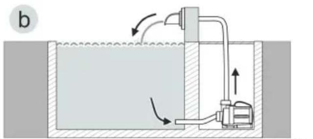
natural_image
Diagram of a fluid system with a tank, pump, and directional arrows indicating flow (no text or labels)PMX0031
C
text_image
IN OutPMX0032
D
text_image
≥ 2 m 230 V ACPMX0033
E
PondoMax Eco Control 5000/10000
PondoMax Eco Control 15000/20000
PondoMax Eco Control 5000/10000/15000/20000
text_image
Control 5000/10000/15000/20000 x Out INPMX0034
F
text_image
≥ 2 m 230 V AC PMXPMX0035
G
text_image
Technical diagram showing five stages of an electric motor assembly with labeled componentsPondoMax Eco Control
5000/10000
text_image
Ø 6 mm 70 mm 111 mm 76 mmPondoMax Eco Control
15000/20000
text_image
Ø 6 mm 72.5 mm 155.5 mm 108 mmPMX0040
H
natural_image
Isometric illustration of an electrical meter mounted on a brick wall, no text or symbols presentPMX0036
|
PondoMax Eco Control 5000/10000
text_image
co Control 5000/10000 1. 2. 3. 4. 5. 45° 2.
text_image
Technical diagram of an electric motor assembly with numbered components and a 45° angle annotationPMX0042
J
PondoMax Eco Control 15000/20000
text_image
Technical diagram of a mechanical device with numbered components and angular annotations
text_image
Technical diagram of a mechanical device with numbered parts and an eye highlighting the internal structure.PMX0038
Original manual. This manual belongs with the unit and must always be passed on together with the unit.
Safety information
Correct electrical installation
- Special regulations apply for electrical installation in outdoor spaces. Only a qualified electrician may perform the electrical installation.
- The qualified electrician has the necessary professional training, knowledge and experience to perform electrical installation in outdoor spaces. The electrician can detect potential dangers and knows how to adhere to regional and national standards, regulations and directives.
- For your own safety, please consult a qualified electrician.
- Only plug the unit into a correctly installed outlet.
- The device is to be supplied through a residual current device (RCD) having a rated residual operating current not exceeding 30 mA.
- Extension cables and power distributors (e.g. outlet strips) must be suitable for outdoor use (splash-proof).
- Protect the plug connection from moisture.
Safe operation
- Disconnect all electrical devices in the water from the power supply before reaching into the water. Otherwise there is a risk of severe injuries or death by electrocution.
- This unit can be used by children aged 8 and above and by persons with reduced physical, sensory or mental capabilities or lack of experience and knowledge if they are supervised or have been instructed on how to use the unit in a safe way and they understand the hazards involved. Do not allow children to play with the unit. Cleaning and user maintenance shall not be carried out by children unless they are aged from 8 years and above and supervised.
- Do not use the unit, if electrical lines or the housing are damaged.
- The supply cord cannot be replaced. If the cord is damaged, the appliance should be scrapped.
- The impeller unit in the pump contains a magnet with a strong magnetic field that may affect the operation of pacemakers or implantable cardioverter defibrillators (ICDs). Keep a distance of at least 0.2 m between the implant and the magnet.
- Never pull on electric cables. In particular, never carry units on their cables.
- Route lines in such a way that they are protected from damage and do not present a tripping hazard.
• Always unplug the unit before working on it. - Never carry out technical changes to the unit.
- Only carry out work on the unit that is described in this manual.
- Only use original spare parts and accessories.
- Should problems occur, please contact the authorised customer service or pontec.
Intended use
Only use the product described in this manual as follows:
- For pumping normal pond water for filter systems, waterfall systems and water course systems.
- While adhering to the technical specifications. (→ Technical data)
The following restrictions apply to the unit:
- Do not use in swimming ponds.
- Never run the unit without water.
- Do not use for commercial or industrial purposes.
- Do not use the unit together with chemicals, food, flammable, explosive substances or other liquids aside from water.
- Do not connect to the domestic water supply.
Product Description
Overview
| ☐ A | Description |
| 1 | ControllerSwitch on / off the pump and control the power level |
| 2 | Pump casing |
| 3 | Filter cage |
| 4 | Stand |
| 5 | Inlet (suction side)With filter cage (3) for submerged installation.With hose sleeve (7) for dry installation. |
| 6 | Outlet (pressure side)With hose sleeve (7) |
| 7 | Hose sleevePondoMax Eco Control 5000 and 10000:- Threaded connection G112 - Hose connection 25, 32 or 38 mmPondoMax Eco Control 15000 and 20000:- Threaded connection G2-Hose connection 32, 38 or 50 mm |
Installation variants
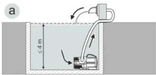
B
- Variant (a): Submerged pump installation
- The pump is positioned in the pond or basin.
– Water flow via the filter cage.
- Variant (b): Dry pump installation
- The pump is installed without the filter cage outside of the pond or basin but lower than the water level.
– Water flow via a hose or a pipe.
Symbols on the unit
 | The unit is dust-tight and water-tight down to 4 m. | |
 | The unit is protected against dust and splash water. | |
 | Protect the unit from freezing temperatures. | |
 | Possible danger for persons with pacemakers. | |
 | Protect the unit from direct sunlight. | |
 | Do not dispose of the unit with normal household waste. | |
 | Read the operating instructions. | |
Installation and connection
The pump can be installed submerged (in water) or dry (outside the water).
The use of the pump is only permitted with observance of the specified water quality. ( Technical data)

WARNING
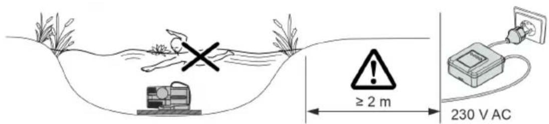
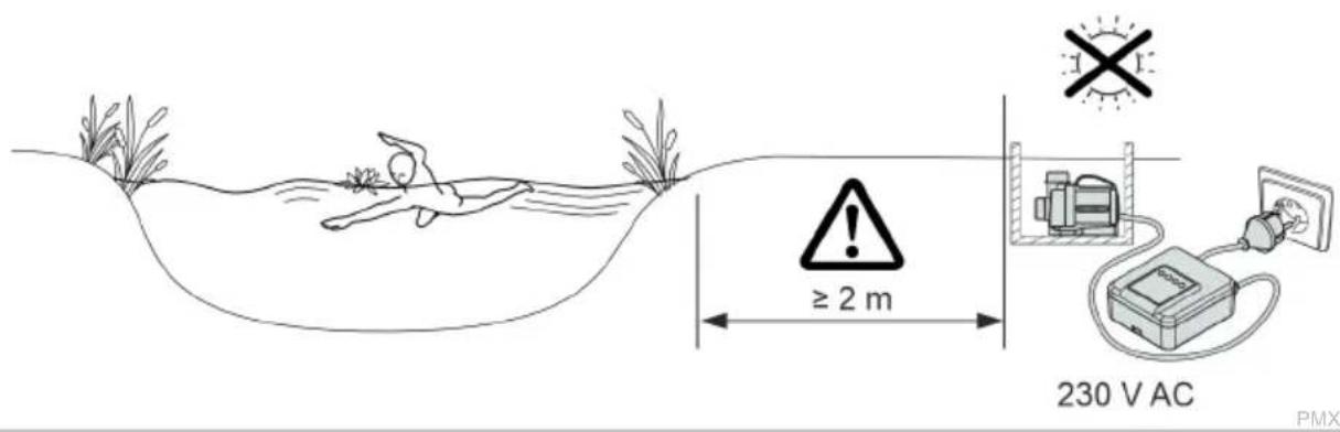
Severe injuries or death due to operation of this unit in a swimming pond. Defective electrical components will electrify the water with dangerous electrical voltage.
▶ Never operate the unit in a swimming pond.

CAUTION
Rotating components in the intake and pressure socket area. Risk of injury when reaching into the sockets.
In particular, observe the following: A unit that has stopped due to overload can start up unexpectedly!
▶ Do not reach into the opening of the intake socket or pressure socket while the power plug is plugged in.
▶ If the sockets are freely accessible during operation, e.g. if no hoses are connected, use a hand guard to secure the sockets. The hand guard is available as an accessory.

Avoid exposing any unit components to direct sunlight for extended periods of time, as this can lead to damage. If necessary, use a protective cover.
Submerged installation of the pump
Connecting
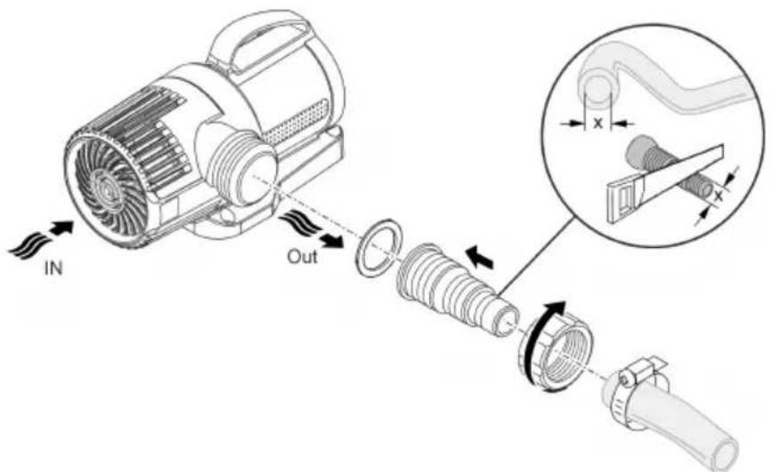
- The larger the line diameter, the smaller the friction losses in the lines and the better the flow rate.
- The line diameter must not be limited unnecessarily by a stepped hose adapter. If necessary, shorten the adapter based on the line diameter.
How to proceed:
□ C
Installation
- Place the pump horizontally on a stable surface.
- Ensure secure and stable positioning of the pump.
- Only operate the pump when it is covered in at least 10 cm of water. Otherwise it may draw in air.
How to proceed:
□D
- EN -
Install the unit at a dry place
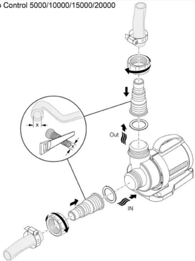
Connecting
- Hoses or pipes can be connected to the inlet (IN) and outlet (OUT).
- Connections for hoses are part of the scope of delivery. Instructions for their installation can be found below.
- To optimise the pump capacity, ensure that the diameter of the intake side line (IN) is not smaller than the diameter of the pressure side line (OUT).
- The larger the line diameter, the smaller the friction losses in the lines and the better the flow rate.
- The line diameter must not be limited unnecessarily by a stepped hose adapter. If necessary, shorten the adapter based on the line diameter.
For dry installation, we recommend pointing the outlet upward.
How to proceed:
□ E
Installation
- Place the pump horizontally on a stable surface.
- Ensure secure and stable positioning of the pump.
- Do not expose the pump to direct sunlight.
- Ensure that the installation site is sufficiently ventilated to prevent overheating of the pump.
How to proceed:
□ F
i It is possible to screw the unit to a suitable surface to ensure stability.
How to proceed:
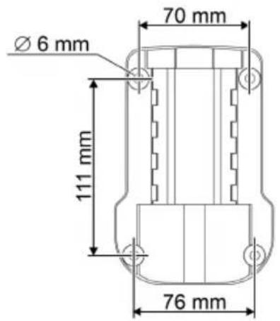
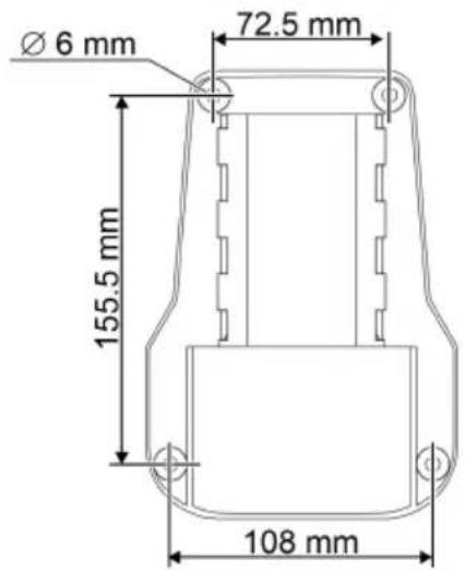
□ G
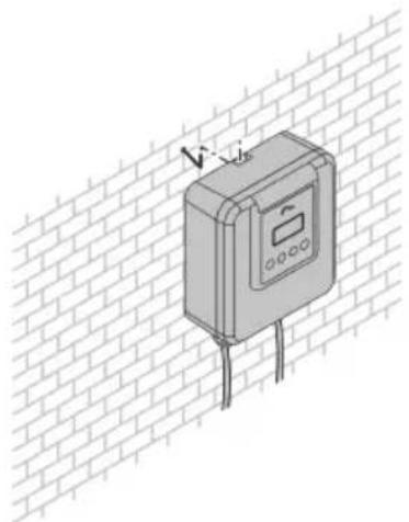
Fastening the controller
- Position the controller at a location protected from sunlight and weather (e.g. on a wall). Attach it to a hook or a screw.
The controller is protected against dust and splash water (IP44). - Ensure that the connections point down.
How to proceed:
□H
Commissioning/start-up
NOTE
The unit will be destroyed if it is operated with a dimmer. It contains sensitive electrical components.
▶ Do not connect the unit to a dimmable power supply.
NOTE
Never allow the pump to run dry. Otherwise the pump may be destroyed.
▶ Only operate the pump when it is submerged or flooded.
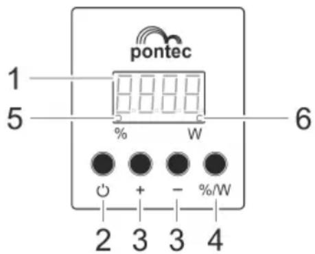
Controller overview
text_image
pontec 1 5 - 6 % W - %/W 2 3 3 4PMX0037
Description
1 Four-digit display
2 Button
3 Button "+" / "-"
4 Button "%/W"
5 %
6 W
Function
- Display of power level as a percentage (%) or in watt (W) with a tolerance.
- Display of the error code in the event of a malfunction.
Switch on/off pump.
Increase or decrease power in levels.
Toggle display between power values in percent (%) or watt (W).
LED lights up when the display shows the power values in percent (%)
LED lights up when the display shows the power values in watt (W)
Operating functions
Commissioning
How to proceed:
-
Plug the power plug into the socket.
The display indicates "OFF". -
Press the button ⏻ on the controller.
The pump is switched on when the display indicates a value or an error code.
Switching off
How to proceed:
- Press the button ⏻ on the controller.
The pump is switched off when the display indicates "OFF".
The pump and controller are only voltage-free when the power plug has been pulled.
Controlling the power level
How to proceed:
- Repeatedly press the "+" or "-" button on the controller to increase or decrease the pump power in percentage levels.
Levels: 0 - 25 - 50 - 60 - 70 - 80 - 90 - 100 %
Maintenance and cleaning
CAUTION
Risk of injury due to unexpected start-up. Internal monitoring functions may switch off the unit and automatically reactivate it.
▶ Disconnect the power plug before carrying out any work on the unit.
NOTE
Do not use aggressive cleaning agents or chemical solutions. These agents can damage the housing, impair the function of the device and harm animals, plants and the environment.
▶ If possible, clean the unit with clear water and a soft brush or a sponge; remove stubborn dirt with the aid of the recommended cleaning agents.
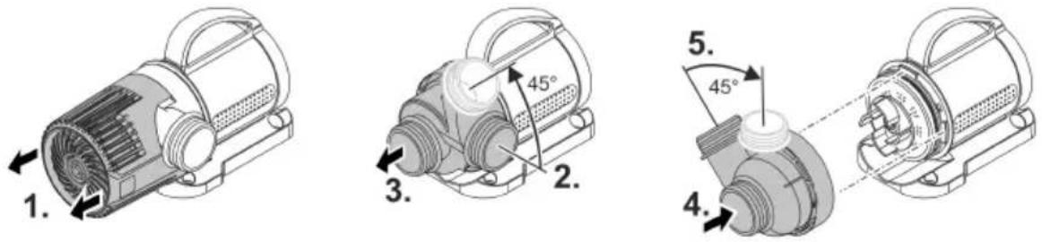
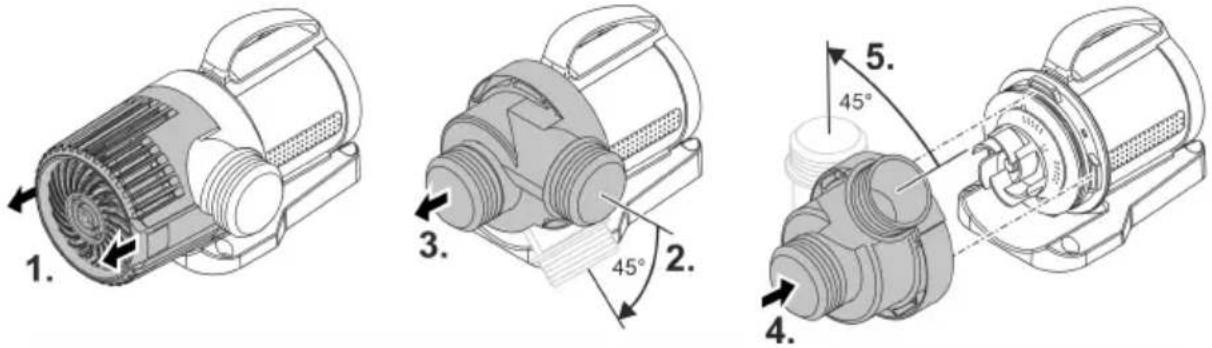
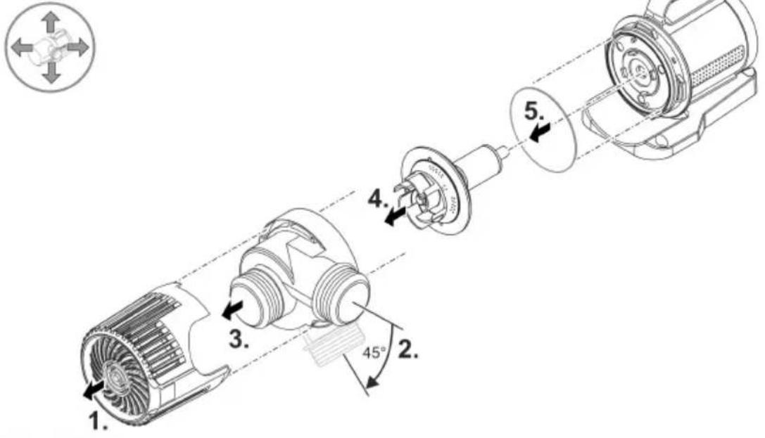
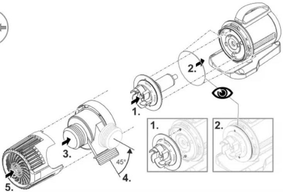
Dismantling and assembling the unit
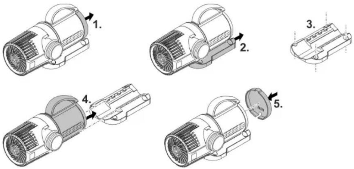
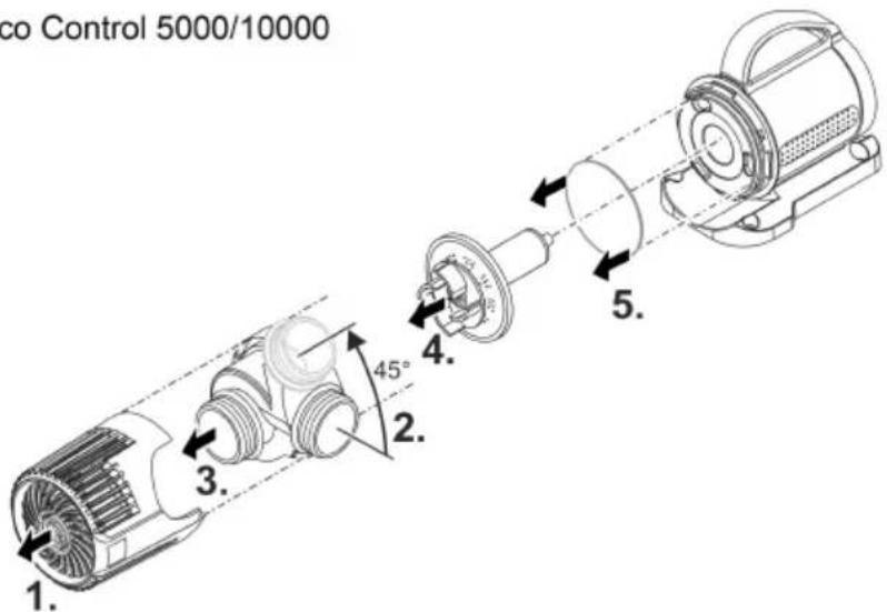
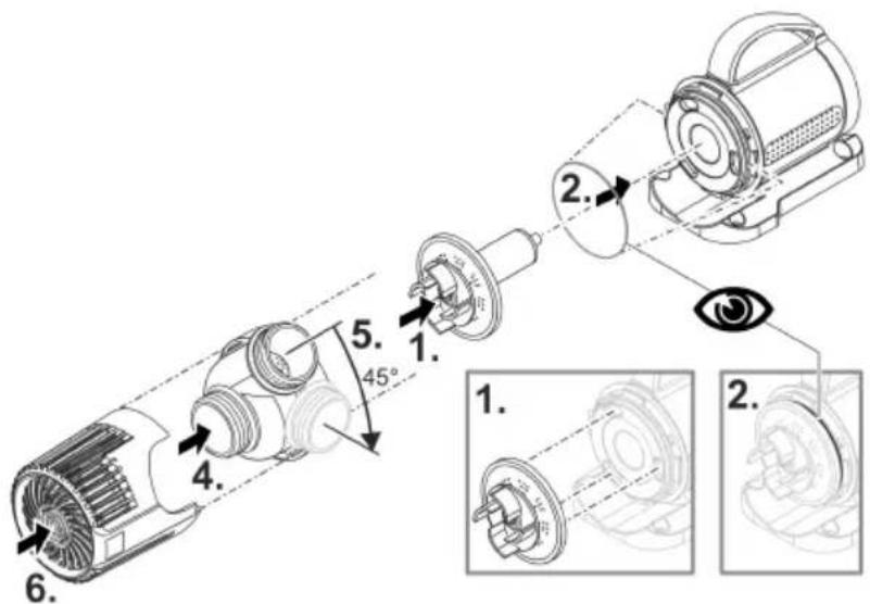
The unit can be dismantled without tools by pulling it apart.
How to proceed:
□ I, J
Cleaning the device
i Clean the unit as required but at least twice per year.
- When cleaning the pump, pay particular attention to the impeller unit and the pump housing.
- Recommended cleaning agent for removing stubborn limescale deposits:
– Vinegar- and chlorine-free household cleaning agent.
• After cleaning, thoroughly rinse all parts in clean water.
Storage/winter protection
The unit is not frost-proof and has to be removed and put into storage if minus temperatures are expected.
How to correctly store the unit:
• Thoroughly clean the unit.
- Check the unit for damage and replace damaged components.
- Protect electrical connections from moisture and dirt.
- Store the pump submerged and in a frost-free environment.
Malfunction remedy
Troubleshooting overview
| Malfunction | Cause | Remedy |
| Pump does not start. | No mains voltage | Check the mains voltage.Check supply lines. |
| Pump not switched on | Switch the pump on at the controller | |
| Pump does not transport fluid | Filter clogged | Clean filter |
| Excessively soiled water | Clean the pump. The pump automatically switches on again once the motor has cooled down. | |
| Pump is set too low | Increase the pump power on the controller | |
| Impeller unit is blocked | Disconnect the power supply and remove obstacle. Then switch the pump on again. | |
| Insufficient delivered quantity | Filter clogged | Clean filter |
| Excessive loss in the supply lines | Select larger hose diameterAdjust stepped hose adapter to hose diameterReduce hose length to minimum necessaryAvoid unnecessary connection elements | |
| Pump is set too low | Increase the pump power on the controller | |
| Pump switches off after operating briefly | Excessively soiled water | Clean the pump. The pump automatically switches on again once the motor has cooled down. |
| Impeller unit is blocked | Disconnect the power supply and remove obstacle. Then switch the pump on again. | |
| Pump has run dry | Flood the pump. Fully submerge the pump for operation in the pond. |
Error messages
The error message automatically disappears after the error has been corrected.
| Error message | Cause | Remedy |
| E 01 | The overcurrent protection has tripped. | Clean impeller unitEnsure that the impeller unit moves with ease. If the impeller unit is sluggish, the pump requires too much power. |
| E 02 | Phase failure; possibly broken cable. | Pull power plug and wait for approx. 10 s. Then switch the pump on again.If the error message is still displayed, there is a cable break. Take the pump to a specialist retailer for repair or send it to PfG. |
| E 03 | The blocking protection has tripped. | Check pump and remove blockage. |
| E 04 | The dry run protection has tripped | Flood pump with water. |
Technical data
| PondoMax Eco Control | 5000 | 10000 | 15000 | 20000 | ||
| Connection voltage | V AC | 220 ... 240 | 220 ... 240 | 220 ... 240 | 220 ... 240 | |
| Mains frequency | Hz | 50/60 | 50/60 | 50/60 | 50/60 | |
| Power consumption | W | 15 ... 55 | 30 ... 90 | 40 ... 135 | 50 ... 190 | |
| Max. pump capacity | I/h | 5000 | 10000 | 15000 | 20000 | |
| Max. pump head | m | 4.5 | 5.5 | 6.5 | 7.5 | |
| Max. immersion depth | m | 4 | 4 | 4 | 4 | |
| Protection type | Pump | IP68 | IP68 | IP68 | IP68 | |
| Controller | IP44 | IP44 | IP44 | IP44 | ||
| Inlet port | Thread | G1 12 | G1 12 | G2 | G2 | |
| Connection, hose | mm | 25, 32, 38 | 25, 32, 38 | 32, 38, 50 | 32, 38, 50 | |
| Outlet port | Thread | G1 12 | G1 12 | G2 | G2 | |
| Connection, hose | mm | 25, 32, 38 | 25, 32, 38 | 32, 38, 50 | 32, 38, 50 | |
| Coarse dirt transport | mm | 8 | 8 | 8 | 8 | |
| Filter supply surface area | cm ^2 | 250 | 250 | 310 | 310 | |
| Water temperature (submerged installation) | During operation | °C | +4 ... +35 | +4 ... +35 | +4 ... +35 | +4 ... +35 |
| Out of operation | °C | -20 ... +35 | -20 ... +35 | -20 ... +35 | -20 ... +35 | |
| Ambient temperature (dry installation) | During operation and convection | °C | +4 ... +30 | +4 ... +30 | +4 ... +30 | +4 ... +30 |
| During operation and forced cooling | °C | +4 ... +40 | +4 ... +40 | +4 ... +40 | +4 ... +40 | |
| Dimensions | Length | mm | 220 | 220 | 255 | 255 |
| Width | mm | 100 | 100 | 130 | 130 | |
| Height | mm | 135 | 135 | 170 | 170 | |
| Cable length | Power cable | m | 2 | 2 | 2 | 2 |
| Pump line | m | 8 | 8 | 8 | 8 | |
| Weight | kg | 4.2 | 4.2 | 5.1 | 5.1 | |
Wear parts
- Impeller unit
Disposal
NOTE
Do not dispose of this unit with household waste.
▶ Dispose of the unit by using the return system provided for this purpose.
▶ Should you have questions, please contact your local disposal company. They will give you information on how to correctly dispose of the unit.
▶ Render the unit unusable by cutting the cables.
Guarantee conditions
PfG grants a 3 year guarantee from the date of sale on proven material and manufacturing faults. Wear parts such as bulbs etc. are exempted from the guarantee. Prerequisite for our guarantee is the presentation of the purchase receipt. Our guarantee will become null and void if the unit is misused, electrically or mechanically damaged by inappropriate use and improper repair by non-authorised workshops. Repairs are reserved for workshops authorised by PfG or by PfG itself. In the case of warranty claims, please return the defective unit or part freight paid to PfG together with a description of the fault and the purchase receipt. PfG reserves the right to invoice repair costs. PfG is not liable for transport damage. Any damage must be claimed against the carrier. Further claims of whatever type, especially consequential damage, are excluded. This guarantee does not affect the final customer's claims against the dealer.
2 Painike
3 Painike "+" / "-"
4 Painike "%/W"
5 %
6 W
Toiminta
text_image
pontec 1 5 - W - %/W - 2 3 3 4 6PMX0037